Steam Power Generation & Steam Power Services | GE Steam Power
American Journal of Mechanical and Materials Engineering 2017; 1(4): 69-77
http://www.sciencepublishinggroup.com/j/ajmme
doi: 10.11648/j.ajmme.20170104.13
Failure Investigation of an In-service Steam Boiler
Okpala Alexander Nwachukwu1, Burubai Woyengi-Ebinipre
2
1Department of Mechanical Engineering, Niger Delta University, Wilberforce Island, Nigeria 2Department of Agricultural & Environmental Engineering, Niger Delta University, Wilberforce Island, Nigeria
Email address:
[email protected] (O. A. Nwachukwu)
To cite this article: Okpala Alexander Nwachukwu, Burubai Woyengi-Ebinipre. Failure Investigation of an In-service Steam Boiler. American Journal of
Mechanical and Materials Engineering. Vol. 1, No. 4, 2017, pp. 69-77. doi: 10.11648/j.ajmme.20170104.13
Received: April 25, 2017; Accepted: May 25, 2017; Published: July 10, 2017
Abstract: Failure investigation was carried out on a refinery steam boiler had a history of good performance with few
leakages and damages that were successfully weld repaired. The steam boiler tubes were observed to have developed several
perforations / punctures on numerous furnace chamber tubes, twenty two years after commissioning. In the course of the
investigation, background data and history of failure were collected with available photographic evidences, visual examination,
low magnification examination, chemical analysis, SEM analysis, EDS analysis, macrostructure examination, microstructure
examination, tensile test hardness and micro-hardness tests. It was concluded that the failure of the tubes were due to upsets in
the water chemistry that has promoted caustic gouging from ID at localized places. Adjustments to boiler water chemistry
which should be made to maintain strict congruent phosphate pH control was then recommended.
Keywords: Caustic, Gouging, Perforations, Steam, Boiler, Tubes, Microstructure
1. Introduction
According to Babcock and Wilcox [2], boiler tube failure
is the leading cause of outages in fossil fuel fired boilers and
to get the boiler back on line and eliminate such future
outages, it is important to determine and eliminate the root
cause. A refinery steam boiler that has had a history of good
performance with few leakages and damages that were
successfully weld repaired was observed to have developed
several perforations/punctures on numerous furnace chamber
tubes, twenty two years after commissioning. The steam
boiler was shut down due to high temperature on the wall and
severe flue gas leakage at numerous locations. Inspection of
the boiler revealed the following observations:
(1) Floor Plate in the flue gas outlet was observed with
perforation.
(2) Vaporizing bank tubes around the flue duct to the
economizer were observed completely covered with
carbon deposits.
(3) There were evidences of flame impingement on the
furnace wall internal tubes.
(4) Numerous perforations/punctures were noticed on the
tubes of the furnace internal wall.
(5) Most burner tips were with oil deposits.
(6) Super heater coil was observed with bulged tubes due
to overheating. The bulge tube observed, may be a
result of stress rupture mechanism due to increased
stress or temperature which Daniels et. al [4] posited
reduces time to rupture.
In view of the severe damage and leakage of the boiler
involving several tubes at once, the root cause analysis
became imperative. Therefore, two halves of the boiler tubes
identified as Sample: A (taken from the furnace internal wall
on the side facing the furnace chamber) and sample: B (taken
from the furnace internal wall on the side facing the flue gas)
were subjected detailed root cause investigation.
2. Methodology
The Failure investigation was done following similar
approach adopted by Guat Peng and Norlia Berahim [6]
Collection of background data and history of failure with
available photographic evidences, visual examination, low
magnification examination, chemical analysis, SEM analysis,
EDS analysis, macrostructure examination, microstructure
examination, tensile test hardness and micro-hardness tests
were carried out. Preparation of micrographs for
microstructure examination was done in accordance with
ASTM E3, methods of preparation of metallographic
specimen [1]. The SEM analysis including the Energy
70 Okpala Alexander Nwachukwu and Burubai Woyengi-Ebinipre: Failure Investigation of an In-service Steam Boiler
dispersive spectrometers (EDS) analysis were done in
consonance with the procedures specified in Chumbley and
Hanke [3]. Based on the investigative findings the root cause
of the problem has been identified.
2.1. Visual Examination
Visual Examination carried out on sample received for
investigation are as under:
Figure 1. ID surface views of sample A showing thick crusts of corrosion
scale. It seems to be porous. The metal wastage is observed having deep and
coarse craters.
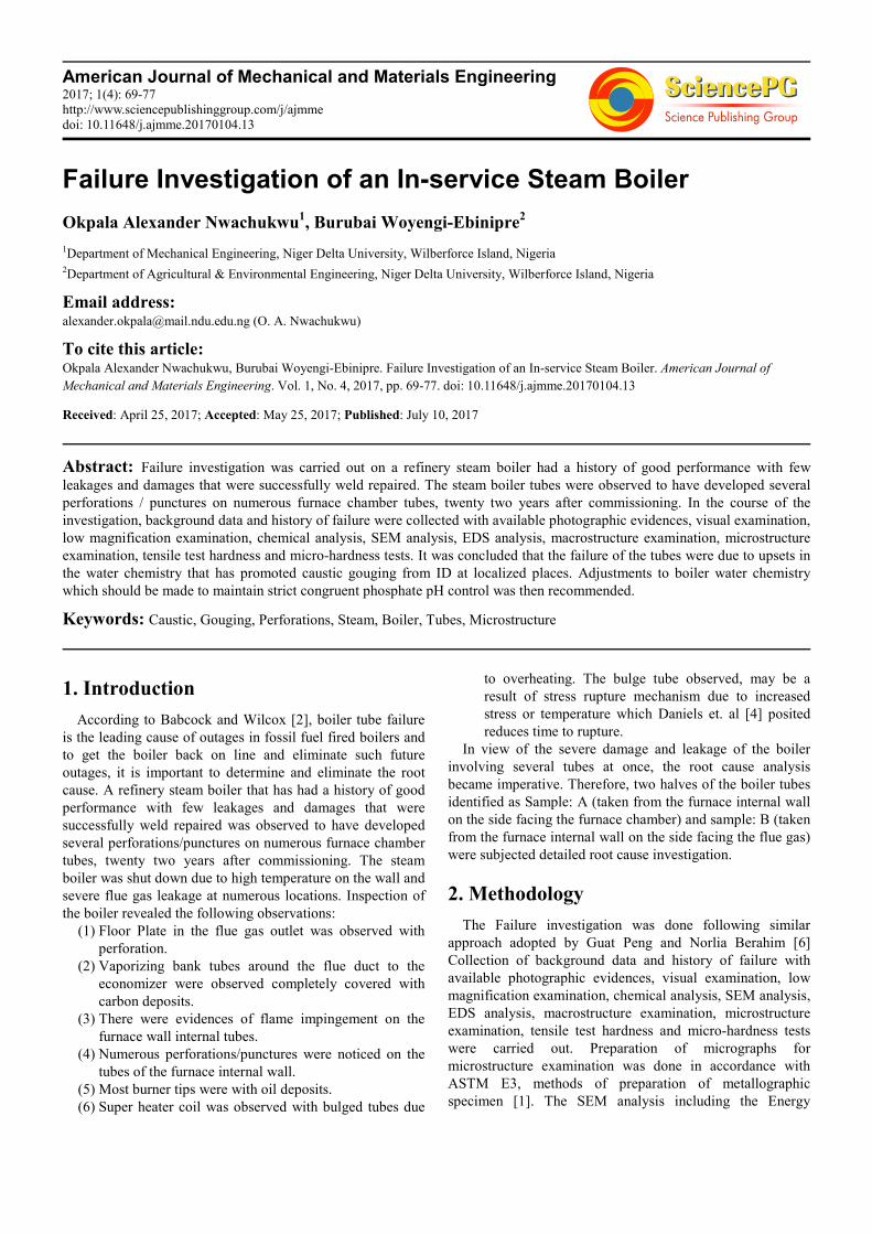
Figure 2. Is the ID surface view of the sample-B showing thin layer of
corrosion scale which had peeled off at several places. Unlike sample-A,
thick crusts of corrosion scale is absent here. Overall internal surface looks
relatively uniform.
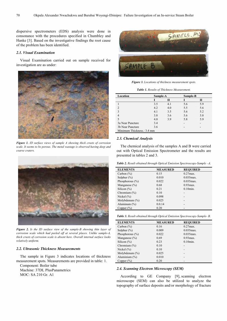
2.2. Ultrasonic Thickness Measurements
The sample in Figure 3 indicates locations of thickness
measurement spots. Measurements are provided in table: 1.
Component: Boiler tube
Machine: 37DL PlusPanametrics
MOC: SA 210 Gr. A1
Figure 3. Locations of thickness measurement spots.
Table 1. Results of Thickness Measurement.
Location Sample-A Sample-B
I II I II
1 3.5 4.1 5.6 5.9
2 4.2 4.0 5.5 5.6
3 4.1 3.5 5.6 5.2
4 3.8 3.6 5.6 5.8
5 4.0 3.9 5.8 5.9
3a Near Puncture 3.4 - -
3b Near Puncture 3.6 - -
Minimum Thickness.: 3.4 mm
2.3. Chemical Analysis
The chemical analysis of the samples A and B were carried
out with Optical Emission Spectrometer and the results are
presented in tables 2 and 3.
Table 2. Result obtained through Optical Emission Spectroscopy-Sample –A.
ELEMENTS MEASURED REQUIRED
Carbon (%) 0.15 0.27max.
Sulphur (%) 0.010 0.035max.
Phosphorous (%) 0.022 0.035max.
Manganese (%) 0.68 0.93max.
Silicon (%) 0.21 0.10min.
Chromium (%) 0.10 -
Nickel (%) 0.098 -
Molybdenum (%) 0.025 -
Aluminum (%) 0.0.14 -
Copper (%) 0.20 -
Table 3. Result obtained through Optical Emission Spectroscopy-Sample- B.
ELEMENTS MEASURED REQUIRED
Carbon (%) 0.16 0.27max.
Sulphur (%) 0.009 0.035max.
Phosphorous (%) 0.022 0.035max.
Manganese (%) 0.69 0.93max.
Silicon (%) 0.23 0.10min.
Chromium (%) 0.10 -
Nickel (%) 0.10 -
Molybdenum (%) 0.025 -
Aluminium (%) 0.010 -
Copper (%) 0.20 -
2.4. Scanning Electron Microscopy (SEM)
According to GE Company [9], scanning electron
microscope (SEM) can also be utilized to analyze the
topography of surface deposits and/or morphology of fracture

American Journal of Mechanical and Materials Engineering 2017; 1(4): 69-77 71
surfaces. SEM was therefore conducted on ID surface to
reveal more details about failure mechanism. The comments
are given next to the individual photographs.
Figure 4. Shows locations where SEM analysis was carried out.
Figure 5. At puncture (100X).
Figure 5 is low magnification view at puncture contours
which displays thinning by way of corrosion attack. Micro
level corrosion attack is observed.
Figure 6. At puncture (500X).
Figure 6 highlights corrosion attack at puncture contours
leading to metal removal at micro level. Micro level pitting is
observed.
Figure 7. Near puncture (500X).
Figure 7 reveals incipient tendency for cracking at
puncture.
Figure 8. Near puncture (1000X).
Figure 8 shows micro pit filled with scale formation on
corroded surface near puncture.

72 Okpala Alexander Nwachukwu and Burubai Woyengi-Ebinipre: Failure Investigation of an In-service Steam Boiler
2.5. Energy Dispersive Spectroscopic (EDS) Analysis
Table 4. EDS Analysis: on black scale at ID surface.
Elements % age
Oxygen 27.68 Sodium 1.79
Aluminium 1.23
Silicon 1.19 Sulphur 0.99
Potassium 1.27
Calcium 0.45 Manganese 0.72
Iron 64.68
Table 5. EDS Analysis: on brown scale at ID surface.
Elements % age
Oxygen 22.47 Sodium 0.79
Aluminum 0.63
Silicon 0.41 Sulphur 0.76
Potassium 0.46
Manganese 0.69 Iron 73.78
2.6. Microstructural Examination
Microstructure examination was carried out at various
locations.
Initially, the examination was done in “As polished‟
condition and then in “Etched‟ condition.
SAMPLE-A
(1) Away longitudinal cross-section
(2) Away transverse cross section
(3) Longitudinal cross section at puncture
SAMPLE-B
Longitudinal Cross-section
SAMPLE-A
AWAY FROM FAILURE LONGITUDINAL CROSS-
SECTION

American Journal of Mechanical and Materials Engineering 2017; 1(4): 69-77 73
Figure 9. ID (100X).
Figure 10. Unetched ID (100X).
Figure: 9 Shows specimen in as mounted condition.
Thinning form ID due to pitting like corrosion damage is
noticed.
Figure: 10 Is unetched view at ID showing corrosion
damage with scaling. Indication of gouging nature of
corrosion is observed.
Figure 11. ID (100X).
Figure 12. OD (100X).
Figure: 11 is etched view having pitting corrosion at the
edge. Matrix is fine ferrite and pearlite.
Figure: 12 is OD microstructure of fine ferrite and pearlite.
No pitting corrosion is observed at the edge.
Figure 13. Is panoramic view at ID edge which highlights metal removal
with gouging (100X).

74 Okpala Alexander Nwachukwu and Burubai Woyengi-Ebinipre: Failure Investigation of an In-service Steam Boiler
TRANSVERSE CROSS SECTION
Figure 14. Shows specimen in as mounted condition. Thinning form ID
damage is noticed.
Figure 15. Is unetched view showing corrosionand scaling.
Figure 16. ID (200X).
Figure 17. OD (200X).
Figure: 16 & 17 are ID & OD etched views showing
corrosion damage at the ID edges. Microstructure is fine
grained ferrite and pearlite structure. Micro pitting is
observed.
PUNCTURE TRANSVERSE CROSS SECTION
Figure 18. Shows specimen in as mounted condition. Coarse gouging from ID that had eventually led to the puncture.
American Journal of Mechanical and Materials Engineering 2017; 1(4): 69-77 75
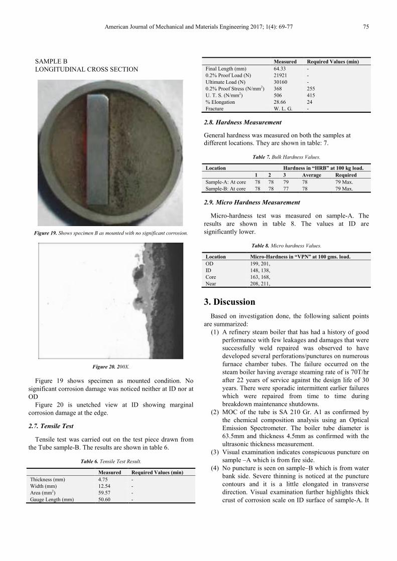
SAMPLE B
LONGITUDINAL CROSS SECTION
Figure 19. Shows specimen B as mounted with no significant corrosion.
Figure 20. 200X.
Figure 19 shows specimen as mounted condition. No
significant corrosion damage was noticed neither at ID nor at
OD
Figure 20 is unetched view at ID showing marginal
corrosion damage at the edge.
2.7. Tensile Test
Tensile test was carried out on the test piece drawn from
the Tube sample-B. The results are shown in table 6.
Table 6. Tensile Test Result.
Measured Required Values (min)
Thickness (mm) 4.75 -
Width (mm) 12.54 -
Area (mm2) 59.57 -
Gauge Length (mm) 50.60 -
Measured Required Values (min)
Final Length (mm) 64.33 -
0.2% Proof Load (N) 21921 -
Ultimate Load (N) 30160 -
0.2% Proof Stress (N/mm2) 368 255
U. T. S. (N/mm2) 506 415
% Elongation 28.66 24
Fracture W. L. G. -
2.8. Hardness Measurement
General hardness was measured on both the samples at
different locations. They are shown in table: 7.
Table 7. Bulk Hardness Values.
Location Hardness in “HRB” at 100 kg load.
1 2 3 Average Required
Sample-A: At core 78 78 79 78 79 Max.
Sample-B: At core 78 78 77 78 79 Max.
2.9. Micro Hardness Measurement
Micro-hardness test was measured on sample-A. The
results are shown in table 8. The values at ID are
significantly lower.
Table 8. Micro hardness Values.
Location Micro-Hardness in “VPN” at 100 gms. load.
OD 199, 201,
ID 148, 138,
Core 163, 168,
Near 208, 211,
3. Discussion
Based on investigation done, the following salient points
are summarized:
(1) A refinery steam boiler that has had a history of good
performance with few leakages and damages that were
successfully weld repaired was observed to have
developed several perforations/punctures on numerous
furnace chamber tubes. The failure occurred on the
steam boiler having average steaming rate of is 70T/hr
after 22 years of service against the design life of 30
years. There were sporadic intermittent earlier failures
which were repaired from time to time during
breakdown maintenance shutdowns.
(2) MOC of the tube is SA 210 Gr. A1 as confirmed by
the chemical composition analysis using an Optical
Emission Spectrometer. The boiler tube diameter is
63.5mm and thickness 4.5mm as confirmed with the
ultrasonic thickness measurement.
(3) Visual examination indicates conspicuous puncture on
sample –A which is from fire side.
(4) No puncture is seen on sample–B which is from water
bank side. Severe thinning is noticed at the puncture
contours and it is a little elongated in transverse
direction. Visual examination further highlights thick
crust of corrosion scale on ID surface of sample-A. It
76 Okpala Alexander Nwachukwu and Burubai Woyengi-Ebinipre: Failure Investigation of an In-service Steam Boiler
is quite porous and has peeled off at several places. On
the other hand only a thin layer of corrosion scale is
noticed on the ID surface of sample-B.
(5) Ultrasonic thickness measurements highlights
conspicuous uneven thinning at puncture location
where as no such thinning is observed in sample-B.
(6) Low magnification view reveals thinning caused on
ID surface of sample- A by corrosion attack and metal
removal at puncture contours and appears like gouging.
(7) SEM analysis reveals thinning due to severe corrosion
attack at puncture contours by way of metal removal.
Micro pitting with incipient tendency for cracking is
also noticed at the place of thinning near puncture.
(8) EDS analysis on black scale on ID surface shows
presence of oxygen, sodium, sulphur, potassium and
chlorine. On brown scale at ID, oxygen, sodium,
sulphur and potassium are present. EDS analysis on
OD surface show presence of carbon, oxygen, sodium,
sulphur, potassium and calcium.
(9) Optical microscopy highlighted the following:
(a) Severe form of corrosion damage from ID which is
marginal at OD. It has typical appearance like metal
gouging. Thick porous adherent scale is observed
from ID side of the tube.
(b) General microstructure of both tubes showed fine
grained ferrite and pearlite structure.
(c) No indication of pitting corrosion of serious nature is
noticed in sample –B despite some corrosion
damage at ID surface.
(10) Tensile test results drawn from sample-B are
satisfactory in nature.
(11) Macro hardness values are acceptable on both the
samples.
(12) Micro hardness values are conspicuously lower on ID
surface.
4. Conclusion
Based on the investigation done following conclusions
were drawn:
The boiler has seen satisfactory life of about 22 years
against the design life being 30 years. Recently failures were
observed in a numbers of the vaporizer tubes; many of them
have severe perforations. This premature failure of the tubes
has occurred through accumulation /compounding effect of
corrosion damage due to thick and porous scaling.
The visual examination, low magnification view and SEM
display severe form of corrosion leading to thinning and
metal removal at puncture location with clear evidence of
gouging. Much thicker layers of corrosion crust are formed
on ID of Sample-A where puncture has taken place than on
sample-B. Major evidences for the accelerated corrosion
phenomenon that is highly localized are obtained in EDS
analysis. It highlights presence of sodium, oxygen, sulphur,
and halogen ions on the scale at ID which clearly point
towards disturbance in the water chemistry. Looking to the
severity of the damage it appears that disturbance in water
chemistry could have been more frequent and severe during
later period of service, prior to failure. Bearing in mind the
presence of sodium, potassium and oxygen on ID scale and
thinning due to severe corrosion leading to groove formation,
damage mechanism by caustic gouging attack appears to be
apparent. Caustic gouging attack occurs as a result of the
following.
Localized corrosion at boiler evaporator areas with high
heat transfer due to deposition of corrosion products/scales,
initially of inert iron oxides, precipitated from the BW -
subsequently formed on site, in combination with boiler
water not in accordance with the specification. This confirms
Corey [8] assertion that failures in boilers can be traced to
water chemistry and treatment. In areas with high heat flux,
first porous (sponge like) deposits of undissolved solids
would form. Soluble impurities of the boiler water penetrate
into these porous deposits/scale accumulate and concentrate
and remain there for longer time –frequently in presence of
an insulating steam phase within the pores. The result is a
material attack caustic gouging.
Normally in high pressure units hydrazine is a common
additive for oxygen scavenging; however, if it is in excess it
will also react with ferric oxide to form ferrous oxide and
water with nitrogen evolution and micro level pitting occurs.
The most probable cause of the failure is that the boiler
tubes perforations appears to be predominantly due to upsets
in the water chemistry that has promoted caustic gouging
from ID at localized places which has eventually resulted in
failure. Indication of oxygen pitting was also observed that
may have added to the damage. This is in line with common
causes of boiler failures listed in TCR [7]
Recommendations
(1) TCR Advanced [10], suggested that caustic gauging
can be mitigated by water chemistry control and design.
The recommendation by Douglas Bain and David
Christophersen [5] suggesting Some adjustments to
boiler water chemistry which should be made to
maintain strict congruent phosphate pH control with
hydroxide or hydrate alkalinity maintained at 0 to (–5.0)
mg/L (ppm) was recommended for this case.
(2) Increased blowdown is recommended as a way of
countering the excessive sodium hydroxide in the
system.
References
[1] ASTM E3 – 01 Standard Guide for Preparation of Metallographic Specimens, ASTM International, West Conshohocken, PA, 2004.
[2] Babcock and Wilcox (2005), Boiler tube Analysis, Babcock and Wilcox Power Generation group, p1.
[3] Chumbley, L. S. and Hanke, L. D (1986), Scanning Electron Spectroscopy, Failure Analysis and Prevention, Vol 11, ASM Handbook, American Society for Metals, pp 1072-1096.

American Journal of Mechanical and Materials Engineering 2017; 1(4): 69-77 77
[4] Daniel, L. C. N, Jansen Renato, Edibeto Bastos, Adrina Rocha and Ibrahim Abud (2010), stress and integrity analysis of a steam super heater tubeof a high pressure boiler, Materials Research, Vol 7, No. 1, Brazil.
[5] Douglas Bain and David Christophersen (2010), Some Common Mechanisms Leading to Failures in Heat Recovery Steam generators, http://www.veoliawatertech.com/crownsolutions/ressources /documents/2/21809, NACE-HRSG-Failure-Analysis.pdf.
[6] Guat Peng and Norlia Berahim (2010), Failure analysis of Power Utility Boiler Tubes, Conference of Electrical Power Supply Industry- CEPSI Conference Proceedings, Taipei, PP 1-28.
[7] TCR (2004), Failure and root cause analysis, a technical White paper, TCR Engineering, India, P8.
http://tcradvanced.com/downloads/tcr-whitepaper-failure-analysis.pdf.
[8] Corey Lehman (2015), Hot water and steam boiler water treatment: Avoiding tube and system failure performance loss, HPAC Engineering publication, http://hpac.com/heating/hot-water-and-steam-boiler-water-treatment.
[9] GE Company (2012), Boiler System failure, G. E water and power publication, https://www.gewater.com/handbook /boiler_water_systems/ch_14_systemfailure.jsp.
[10] TCR Advanced (2016), Boiler Tube Failure investigation, TCR Advanced Engineering publication, India, P4, http://www.tcreng.com/download/Boiler-Tube-Investigation.pdf.