FAILURE ANALYSIS - Structural Integrity Associates · 2020-03-17 · Fractured shaft FAILURE...
2
Fractured shaft FAILURE ANALYSIS Failure is defined as any change in a component that prevents satisfactory performance of its intended function. Understanding why a component failed is important for several reasons. First, a determination of the mode of damage responsible for the failure is an essential component of any root cause analysis, although in most cases it is not sufficient for identifying the root cause of failure. Second, understanding a component failure provides essential information for preventing additional or similar failures, as well as ensuring appropriate repair or replacement decisions are made. Perhaps most importantly, an erroneous or incomplete analysis can be worse than no analysis at all, since this can prompt inappropriate responses that do not address the basic cause of failure or even increase the potential for additional failures. The degrees to which a failure analysis can be applied range from simply determining the failure mode to performing a full root cause analysis of the failure event. For each situation that occurs, the approach required should be evaluated to determine the level of metallurgical evaluation or engineering effort that should be expended. Identifying the mode of a failure can range from relying on a thorough visual examination by a competent failure analyst to a full laboratory analysis consisting of some or all of the following tasks: ■ Visual Examination and Photo-Documentation • A preliminary diagnosis of the mechanism can often be made based on visual examination of the macroscopic damage features; this will determine the number and location of specimens to be removed for destructive analysis. • Photo-documentation will record distinctive features of the damage prior to sample cutting and can preserve information on locations of specimens removed for destructive analysis. ■ NDE, Where Appropriate Before the component is sectioned, it might be examined by various non-destructive techniques (e.g., dye penetrant inspection or phased array ultrasonics) to help identify areas for sectioning or assess the effectiveness of an NDE technique to locate similar damage in other components. ■ Chemical Composition Analysis A chemical analysis is performed to determine if the component material is within specification, and if any particular additional elements (unspecified or trace) are present that could adversely affect material performance. ■ Dimensional Measurements Dimensional measurements include the major dimensions such as outer and inner diameters and component thickness. They can be used to identify the location and magnitude of material wastage or wall loss. For tubular components, dimensional measurements can also be used to identify the degree of service-induced swelling, which is a measure of accumulated creep damage. Cracked turbine blades Cracking identified by WFMT A ring section showing external wall loss as well as swelling
Transcript of FAILURE ANALYSIS - Structural Integrity Associates · 2020-03-17 · Fractured shaft FAILURE...
Fractured shaft
FAILURE ANALYSISFailure is defined as any change in a component that prevents satisfactory performance of its intended function. Understanding why a component failed is important for several reasons. First, a determination of the mode of damage responsible for the failure is an essential component of any root cause analysis, although in most cases it is not sufficient for identifying the root cause of failure. Second, understanding a component failure provides essential information for preventing additional or similar failures, as well as ensuring appropriate repair or replacement decisions are made. Perhaps most importantly, an erroneous or incomplete analysis can be worse than no analysis at all, since this can prompt inappropriate responses that do not address the basic cause of failure or even increase the potential for additional failures. The degrees to which a failure analysis can be applied range from simply determining the failure mode to performing a full root cause analysis of the failure event. For each situation that occurs, the approach required should be evaluated to determine the level of metallurgical evaluation or engineering effort that should be expended. Identifying the mode of a failure can range from relying on a thorough visual examination by a competent failure analyst to a full laboratory analysis consisting of some or all of the following tasks:
■ Visual Examination and Photo-Documentation• A preliminary diagnosis of the mechanism can often be made based on visual
examination of the macroscopic damage features; this will determine the number and location of specimens to be removed for destructive analysis.
• Photo-documentation will record distinctive features of the damage prior to sample cutting and can preserve information on locations of specimens removed for destructive analysis.
■ NDE, Where Appropriate Before the component is sectioned, it might be examined by various non-destructive techniques (e.g., dye penetrant inspection or phased array ultrasonics) to help identify areas for sectioning or assess the effectiveness of an NDE technique to locate similar damage in other components.
■ Chemical Composition Analysis A chemical analysis is performed to determine if the component material is within specification, and if any particular additional elements (unspecified or trace) are present that could adversely affect material performance.
■ Dimensional Measurements Dimensional measurements include the major dimensions such as outer and inner diameters and component thickness. They can be used to identify the location and magnitude of material wastage or wall loss. For tubular components, dimensional measurements can also be used to identify the degree of service-induced swelling, which is a measure of accumulated creep damage.
Cracked turbine blades
Cracking identified by WFMT
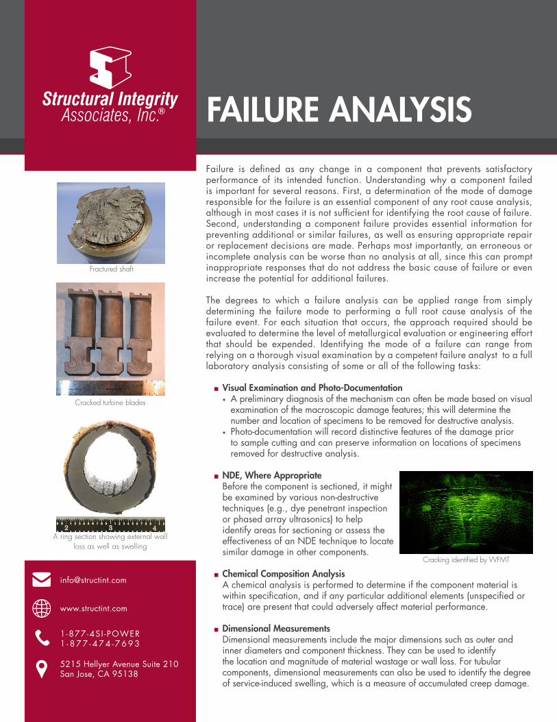
A ring section showing external wallloss as well as swelling
09 11 2018 150
■ Hardness Evaluation and/or Mechanical Properties Testing Hardness tests can easily be performed on metallurgical sections and provide an indication of the metallurgical condition of the material. Hardness values can also be used to estimate tensile strength. Other mechanical property testing, including elevated temperature properties (creep strength) and fracture toughness, can be performed as part of more detailed investigations.
■ Metallography Metallographic evaluation allows for assessment of component microstructure and microstructural degradation (spheroidization, graphitization or transformation). It also provides information on damage type, extent, and morphology (cracking/fracture path, rupture features, corrosion, pitting, and cavitation). The appearance and thickness of oxides/scales/deposits can also be assessed.
■ Fractography If the sample includes a fracture surface, this surface can be examined to evaluate the fracture characteristics. The morphology of the fracture surface provides insight into the mode of failure (transgranular/intergranular, ductile/brittle, etc.) and may also indicate the presence of precipitates, cavities or foreign species that may have caused or contributed to the failure. Fracture surfaces are commonly examined with a stereomicroscope, digital Keyence microscope, or with a scanning electron microscope, which provides both depth of field as well as high magnification views of the damage.
■ Characterization of Oxide/Deposit (EDS/XRD) Often surface oxides, deposits, or corrosion products play a significant role in the damage mechanism either by directly causing wall loss or attack of the metal, or by acting as a secondary contributor to a failure (e.g. internal oxide scale “insulating” a steam touched tube and causing an increase in the tube metal temperature). Characterization of these oxides or deposits includes identifying the elements or compounds present, mapping the elemental constituents to show how they are dispersed throughout the layers, and examining the morphology at low and high magnifications.
Microhardness traverse through fractured weld
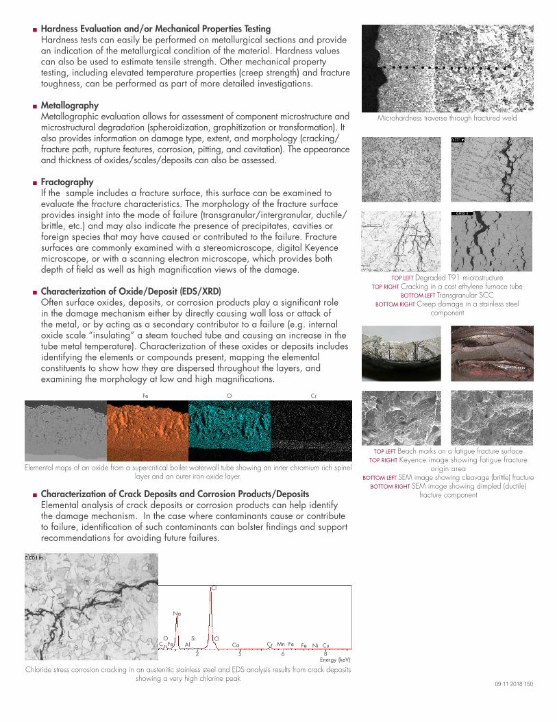
■ Characterization of Crack Deposits and Corrosion Products/Deposits Elemental analysis of crack deposits or corrosion products can help identify the damage mechanism. In the case where contaminants cause or contribute to failure, identification of such contaminants can bolster findings and support recommendations for avoiding future failures.
TOP LEFT Degraded T91 microstructureTOP RIGHT Cracking in a cast ethylene furnace tube
BOTTOM LEFT Transgranular SCCBOTTOM RIGHT Creep damage in a stainless steel
component
Elemental maps of an oxide from a supercritical boiler waterwall tube showing an inner chromium rich spinel layer and an outer iron oxide layer.
Chloride stress corrosion cracking in an austenitic stainless steel and EDS analysis results from crack deposits showing a very high chlorine peak
CO
Fe
Na
AlSi
Cl
ClCa Cr Mn Fe CuFe Ni
2 865Energy (keV)
Fe O Cr
TOP LEFT Beach marks on a fatigue fracture surfaceTOP RIGHT Keyence image showing fatigue fracture
origin areaBOTTOM LEFT SEM image showing cleavage (brittle) fracture
BOTTOM RIGHT SEM image showing dimpled (ductile) fracture component