Failure Mode Effects Criticality Analysis (FMECA) - Giant Mine ...

I
Republic of Sudan
Ministry of Higher Education and Scientific Research
Sudan University of Science and Technology
School of Mechanical Engineering
FAILURE ANALYSIS OF TRANSFORMER BY
USING FAILURE MODES, EFFECT AND
CRITICALITY ANALYSIS
A graduation project is submitted to the School of Mechanical Engineering in
partial fulfillment of the requirements for the degree of Bachelor in Mechanical
Engineering-Production
PREPARED BY:
ANWAR ADAM SULIEMAN
SUPERVISOR:
Dr. KHAWAT ALI ALFAKI
October, 2016

II
Dedication
I dedicate this research to my Parents, lecturers, who taught me to think,
understand and express I earnestly feel that without their inspiration, able
guidance and dedication I would not be able to pass through the tiring
process of this research.

III
Acknowledgment
First and foremost, I like thank my family, especially my parents, for
their encouragement, patient, and assistance over years. I would also like
to express my gratitude and appreciation to Dr. ELkhawad Ali Alfaki for
all the help and guidance he provided throughout my research.

IV
ABSTRACT
This project presents a failure analysis of power transformer using Failure
Modes, Effect and Criticality Analysis (FMECA) method. With the aims
to analyzing potential failure modes, possible causes, their effects and
find reliability, risk priority number and rank. A general FMECA for
outage causes of 500kv power transformer is presented, including the
local effects and final effects, and recommended actions to avoid these
outages. Assignment of risk priority numbers to various outage causes,
which might occur at this voltage level are, carefully considered.

V
المستخلص
اسثاب انًًكنة ًجاثيشه ً ايضا , يحًثم انيذف ين ىزا انًششًع في جحهيم انًاط انفشم انًححًهة
ايجاد انًٌثٌقية ًانشقى اًنٌية انخطش ً جشجيثيا عهى حسة االًنٌية نًحٌل تاسحخذاو انًنيجية
نهًحٌل (االعطال)جحهيم جاثيش حشجية انًاط انفشم ًجحًثم يشكهة انثحث في دساسة انقطٌعات
جحهيم جاثيش نزنك جى جطثيق انًنيجية,حيث اعحثش ىزه انقطٌعات تًثاتة انفشم ( كيهٌ فٌنث500)
جى جحهيم كم انًاط انفشم انًححًهة ً االسثاب حذًثو ً . حشجية انًاط انفشم عهى ىزا انًحٌل
جاثيشاجو سٌاء كانث جاثيش عهى جضء يعين ين انًحٌل اً عهى كم اننظاو ً جشجية ىزه االعطال
نقذ جى اجخار اجشاءات انٌقائية انًناسثة نحقهيم ظيٌس ىزه .عهى حسة خطٌسجيا عهى انًحٌل
. حذًثو ححى يحًكن انًحٌل ين اداء ًظيفحو تانشكم انًطهٌب االعطال ًاصانة اسثاب

VI
Table of Contents
Dedication .................................................................................................. II
Acknowledgment ...................................................................................... III
ABSTRACT .............................................................................................IV
V ...................................................................................................... المستخلص
List of Tables ......................................................................................... VIII
List of Figures ...........................................................................................IX
Chapter one: Introduction ....................................................................... 1
1.1- Introduction .................................................................................................................... 1
1.2- Problem Statement .......................................................................................................... 2
1.3-Objectives ........................................................................................................................ 2
1.4- Project Significance ........................................................................................................ 2
1.5- project Scope .................................................................................................................. 3
1.6- Project Layout................................................................................................................. 3
Chapter Two: Literature Review ............................................................ 5
2-1 Failure Modes, Effect and Criticality Analysis (FMECA) .............................................. 5
2.1.1- Standards and History .............................................................................................. 6
2.1.2- CRITICALITY ANALYSIS (CA) .......................................................................... 6
2.1.3- FMECA APPLICATION ........................................................................................ 7
2.1.4- FMECA DESCRIPTION ........................................................................................ 7
2.1.5- FMECA Types ......................................................................................................... 9
2.1.6- FMECA Benefits ................................................................................................... 10
2.1.7- Definition of FMECA Terms ................................................................................. 10
2.1.8-Team effort ............................................................................................................. 13
2.2 Power transformer .......................................................................................................... 14
2.2.1-Transformer Construction ...................................................................................... 15
2.2.2- Some major and minor causes of power transformer outages ............................. 15
2.3- Related Studies ............................................................................................................. 18
2.3.1- Study (1): ................................................................................................................ 18
2.3.2- Study (2): ............................................................................................................... 19
2.3.3- Study (3): ............................................................................................................... 19
2.3.4- Study (4): ............................................................................................................... 21
Chapter Three: Methodology ................................................................ 23
VII
3.1-Analysis Methodology ................................................................................................... 23
3.2- How to Evaluate Risk Priority Number (RPN)? ........................................................... 26
Chapter Four: Results and Discussion ................................................. 29
4.1- Power Transformer Components .................................................................................. 29
4.2 FMECA for 500kv transformers .................................................................................... 31
Chapter Five: Conclusion and Recommendation ................................ 37
Conclusion ........................................................................................................................... 37
Recommendation ................................................................................................................. 37
References: ............................................................................................... 38

VIII
List of Tables
Table 3.1 Evaluation criteria for severity, occurrence and
detection…………………………………………………………27
Table 4.1 Transformer outage causes……………………………31
Table 4.2 Minor Failures FMECA of Transformer………………33
Table 4.3 Major Failures FMECA of Transformer………………35

IX
List of Figures
Fig 2.1. Basic construction of transformer…………………………..15
Fig 2.2. Failure of transformer………………………………………16
Fig 2.3. Failure due to moisture content in oil……………………….16
Fig 2.4. Lightning strike- Transmission tower………………………..17
Fig 2.5.Bird nest on transmission system…………………………….17
Fig 3.1.Systematic procedures to create FMECA……………………23

X
CHAPTER ONE
Introduction

1
Chapter one: Introduction
1.1- Introduction
Every machine and process in daily manufacturing /service operations
has it owns modes of failure. An analysis of these failures will help to
focus and understand the impact they may portray into the day to day
processes and operations. It is important to determine the causes and
characteristics of failures in order to prevent future occurrence and
improve the performance of the device, component and structure.
One of the well-known methods in conducting the failure analysis is the
Failure Modes, Effect and Criticality Analysis (FMECA) [1].
The FMECA is first developed as formal design methodologies in the
1960’s by the aerospace industry with their obvious reliability and safety
requirements, in which it is extended version of Failure Modes and Effect
Analysis (FMEA). Since then, it has been extensively used to help in
ensuring the safety and reliability of system employed in a wide range of
industries.
Failures of transformers in sub-transmission systems not only reduce
reliability of power system but also have significant effects on power
quality since one of the important components of any system quality is
reliability of that system. The first step of a system failure analysis and
reliability study is often the Failure Modes, Effects and Criticality
Analysis (FMECA), one of several methods used for risk assessment and
management thorough failure analysis. In other words, FMECA is an
important procedure to identify and assess consequences or risk
associated with potential failure modes [2]. A FMECA is a qualitative or
quantitative analysis and typically includes a listing of failure modes,
possible causes for each failure, effects of the failure and their seriousness
and corrective actions that might be taken.

2
1.2- Problem Statement
Transformers have a key role in power systems and their reliability
directly affects the reliability of the whole network. Outage of
transformers is considered a failure, since it is an event that determines a
fault state (the transformer cannot perform its specified function
1.3-Objectives
1- Analyzing potential failure modes, possible causes and their
effects for power transformer using FMECA.
2- Find the Reliability, Risk Priority Numbers and Rank for power
transformer.
1.4- Project Significance
Power transformers in addition to playing an important role in the
efficiency and reliability of power transmission networks, are also the
most expensive network equipment. It is important to know when the
transformer is the most dangerous element because it contains a great
quantity of oil in contact with high voltage elements and this may lead to
fires and forced unexpected outages. Thing which favors the risk of
outages in case of abnormal circumstances or technical failures. So, it is
necessary to plan and to focus the efforts by set of priorities with a
general aim is to minimizing unexpected outage and improve the
reliability of the system, and consequently, to reduce their failure risk by
using the FMECA.

3
1.5- project Scope
This project contains the failure modes, effects, and criticality
analysis for all parts of the power transformer (500kv). This FMECA
analysis consists of an outlining of all possible failure modes of all
elements, possible causes and then a determination of the effects and
criticality of these failure modes.
1.6- Project Layout
This project consists of five chapters:
Chapter one: Introduction
Chapter two: Literature Review
Chapter three: Methodology
Chapter four: Results and Discussion
Chapter five: Conclusion and Recommendation

4
CHAPTER TWO
Literature Review

5
Chapter Two: Literature Review
2-1 Failure Modes, Effect and Criticality Analysis (FMECA)
FMECA extends FMEA by introducing the notion of criticality
into the analysis. All aforementioned characteristics of FMEA are
applicable to FMECA as well. In addition a criticality analysis is
performed as part of the procedure. We may distinguish two basic types
of criticality analysis, according to MIL-STD-1692A standard [1]:
The FMECA is composed of two separate analyses, the Failure Mode and
Effects Analysis (FMEA) and the Criticality Analysis (CA). The FMEA
analyzes different failure modes and their effects on the system
while the CA classifies or prioritizes their level of importance based on
failure rate and severity of the effect of failure. The ranking process of the
CA can be accomplished by utilizing existing failure data or by a
subjective ranking procedure conducted by a team of people with an
understanding of the system. Although the analysis can be applied to any
type of system, this manual will focus on applying the analysis to a
facility The FMECA should be initiated as soon as preliminary design
information is available. The FMECA is a living document that is not
only beneficial when used during the design phase but also during system
use. As more information on the system is available the analysis should
be updated in order to provide the most benefit. This document will be
the baseline for safety analysis, maintainability, and maintenance
Plan analysis, and for failure detection and isolation of subsystem design.
Although cost should not be the main objective of this analysis, it
typically does result in an overall reduction in cost to operate and
maintain the facility.

6
2.1.1- Standards and History
There are many standards and quality systems incorporating
FMEA/FMECA, often specifically designed for certain area, such as
automotive and avionic industry, power plants (especially nuclear), space
programs, etc.
The first standard which introduced the ideas of FMEA and
FMECA was, however, a U.S. military standard MIL-STD-1629[1],
published in 1949 as a procedure and standardized in 1974. Even before
standardization, many industries adopted these methods in their
processes. This standard was later updated by MIL-STD-1629A. Other
industry standards include for instance SAEJ1739 or ALAG FMEA-3. In
1960s FMEA and FMECA began to be used in NASA and its partners
and since then it was used in many NASA programs, including Apollo,
Viking, Voyager and Galileo. In the same time, the civil avionic industry
also started to use these techniques in designing aircraft. In 1970s it
spread also to automotive industry, beginning with the Ford Motor
Company.
2.1.2- CRITICALITY ANALYSIS (CA) The CA is an analysis procedure for associating failure
probabilities with each failure mode. Since the CA supplements the
FMEA and is dependent upon information developed in that analysis, it
should not be attempted without first completing the FMEA.
The CA is probably most valuable for maintenance and logistic
support oriented analyses since failure modes which have a high
probability of occurrence (high criticality numbers) require investigation
to identify changes which will reduce the potential impact on the
Maintenance and logistic support requirements for the system.
The analysis approach to be used for the CA will generally be dictated by
the availability of specific configuration data and failure rate data. There

7
are two approaches for accomplishing the CA. One is the qualitative
approach which is appropriate only when failure rate data are not
available. The preferred method is the quantitative approach which is
utilized where failure rate data have been derived.
2.1.3- FMECA APPLICATION
A FMEA and CA when performed concurrently are referred to as a
FMECA. The FMECA, if applied properly, can be one of the most
beneficial and productive tasks in a well-structured reliability
program[1][2]. Since individual failure modes are listed and evaluated in
an orderly, organized fashion, the FMECA serves to verify design
integrity, identify and quantify undesirable failure modes and document
reliability risks. Results of a FMECA can be used to provide the rationale
for changes in operating procedures, maintenance strategies, and design
to remove undesirable failure modes.
Although the FMECA is an essential reliability task, it is a
concurrent engineering tool which should be used to supplement and
support other engineering tasks by identifying areas in which effort
should be concentrated. FMECA results not only provide design
guidance, but can be used advantageously during maintenance planning
analysis, logistics support analysis, survivability and vulnerability
assessments, safety and hazards analysis, and for fault detection and
isolation design. This coincident use of the FMECA must be considered
by program management during FMECA planning and every effort made
to prevent duplication of analyses by the various program elements which
utilize FMECA results.
2.1.4- FMECA DESCRIPTION
An FMECA is a powerful tool to optimize the performance/life-
cycle cost tradeoffs between mission reliability and basic reliability at the

8
black box or subsystem level, where these tradeoffs are most
appropriately analyzed and evaluated[3]. Potential design weaknesses are
determined by using functional block diagrams, reliability block
diagrams, engineering schematics, and mission rules (mission functions,
operational modes, environmental profiles, and times) to systematically
identify the likely modes of failure, the possible effects of each failure
(which may be different for each life/mission profile phase), and the
criticality of each effect on safety, readiness, mission success, demand for
maintenance/logistics support, or some other outcome of significance. A
reliability criticality number may be assigned to each failure mode
usually based on failure effect, severity and probability of occurrence.
These numbers are sometimes used to establish corrective action
priorities, but because of the subjective judgment required to establish
them, they should be used only as indicators of relative priorities. The
FMECA can also be used to confirm that new failure modes have not
been introduced in transforming schematics into production drawings.
The initial FMECA should be done early in the conceptual phase, and
because limited design definition may be available, only the more
obvious failure modes may be identified. This can help identify many of
the single failure points, some of which can be eliminated by simple
design changes. As greater mission and design definitions are
developed in the validation and full scale development phases, the
analysis can be expanded to successively-more-detailed levels and
ultimately to the part level. The usefulness of the FMECA is dependent
on the skill of the analyst, the available data, and the information the
analyst provides as a result of the analysis.
The FMECA format is tailor able and additional pertinent
information such as, failure indication, anticipated environment under
which the failure may be expected to occur, time available for operational

9
corrective action, and the corrective action required could be included.
The amount of detail and type of information supplied is a function of
mission criticality.
In general, engineering manpower should be focused on those
potential failures which imperil the crew or preclude mission completion.
FMECA results may suggest areas where the judicious use of redundancy
can significantly improve mission reliability without unacceptable impact
on basic reliability, and where other analyses such as electronic parts
tolerance or sensitivity analyses be performed, or other provisions such as
environmental protections be considered.
Additionally, FMECA results can be used to provide rationale for
operating procedures used to ameliorate undesirable failure modes and
document residual risks.
2.1.5- FMECA Types
Three types of FMECA are described when developing FMECAs
at the component, assembly, subsystem, and system levels[2][3]. These
are functional, interface, and hardware. These three FMECA types follow
the development phases as the evaluation proceeds from a “functional
evaluation of failure modes and effects” to increased levels of detail as
potential problems are surfaced and additional analyses in selected areas
are needed (e.g., at redundancy cross-straps). Functional FMECAs are
performed and documented for proposals, trade studies, and PDRs to
evaluate and provide support for the resulting design redundancy
architecture. Interface and hardware FMECAs then follow at the piece-
part/harness level as the detailed design unfolds during the CDR
Timeframe.
Because modified and improved designs are based upon heritage
designs, detailed design data during the PDR time-frame must be made

10
available to complete a detailed analysis for evaluating the design
candidates during trade studies.
2.1.6- FMECA Benefits
The FMECA facilitates identification of potential design reliability
problem areas which must be eliminated or their effect minimized, by
design modification or tradeoffs [4]. Specific defects identified can
include:
Circuit failures that may cause the failure of a related critical circuit
Areas where fail safe or fail soft features are required Primary failures
which may cause costly secondary failures Information and knowledge
gained by performing the FMECA can also be used as a basis for trouble
shooting activities, maintenance manual development and design of
effective built-in test techniques. The FMECA provides valuable
information for maintainability, safety and logistic analysis.
2.1.7- Definition of FMECA Terms
The following list describes important terms often used in
FMECA[1][3][4].
Compensating Provision: Actions available or that can be
taken to negate or reduce the effect of a failure on a system.
Corrective Action: A documented design, process or procedure
change used to eliminate the cause of a failure or design
deficiency.
Criticality: A relative measure of the consequences of a failure
mode and the frequency of its occurrence.
Criticality Analysis (CA): A procedure by which each
potential failure mode is ranked according to the combined
influence of severity and probability of occurrence.

11
Damage Effects: The results or consequences a damage mode
has upon system operation, or function.
Damage Mode: The way by which damage occurs and is
observed.
Damage Mode and Effects Analysis: The analysis of a
system or equipment to determine the extent of damage sustained
from given levels of weapon damage mechanisms and the effects
of such damage on the continued operation and mission of the
specified system or equipment.
Detection Method: The method by which a failure can be discovered
by the system operator under normal system operation or by a
maintenance crew carrying out a specific diagnostic action.
End Effect: The consequence a failure mode has upon the
operation, function or status at the highest indenture level.
Failure Cause: The physical or chemical processes, design
defects, quality defects, part misapplication or other processes
which are the basic reason for failure or which can initiate the
physical process by which deterioration proceeds to failure.
Failure Effect: The consequence a failure mode has upon the
operation, function or status of a system or equipment.
Failure Mode: The way in which a failure is observed, describes
the way the failure occurs, and its impact on equipment operation.
Fault Isolation: The process of determining the location of a fault to the
indenture level necessary to effect repair.
Indenture Levels: The levels which identify or describe the
relative complexity of an assembly or function.

12
Local Effect: The consequence a failure mode has on the
operation, function or status of the specific item being analyzed.
Maintainability Information: A procedure by which each potential failure
mode in a system is analyzed to determine how the failure is detected and
what actions will be needed to repair the failure.
Mission Phase Operational Mode: The statement of the
mission phase and mode of operation of the system or equipment in
which the failure occurs.
Next Higher Level Effect: The consequence a failure mode
has on the operation, functions, or status of the items in the next
higher indenture level above the specific item being analyzed.
Primary Damage Effects: The results or consequences a
damage mode has directly on a system or the components of the
system.
Redundancy: The existence of more than one means for
accomplishing a given function.
Secondary Effects: The results or consequences indirectly
caused by the interaction of a damage mode with a system,
subsystem or component of the system.
Severity: Considers the worst possible consequence of a failure
classified by the degree of injury, property damage, system damage
and mission loss that could occur.
Single Point Failure: The failure of an item which can result in
the failure of the system and is not compensated for by redundancy
or alternative operational procedure.

13
2.1.8-Team effort
The FMECA should be a catalyst to stimulate ideas between the
design engineer, operations manager, maintenance manager, and a
representative of the maintenance personnel (technician)[3].
The team members should have a thorough understanding of the
systems operations and the mission's requirements. A team leader should
be selected that has FMECA experience. If the leader does not have
experience, then a FMECA facilitator should be sought. If the original
group of team members discovers that they do not have expertise in a
particular area during the FMECA then they should consult an individual
who has the knowledge in the required area before moving on to the next
phase.
The earlier a problem in the design process is resolved, the less
costly it is to correct it. Two basic types of criticality analysis, according
to MIL-STD-1692A standard[1]:
• Qualitative – this approach is very similar to computing of the risk
priority numbers (RPNs), but only severity and occurrence are taken into
account. Failure modes are compared according to the Criticality Matrix
which has severity levels on the horizontal axis and occurrence on the
vertical axis.
• Quantitative – this type of criticality analysis computes modal
criticality numbers (𝐶𝑚) for each failure mode of each item and item
criticality numbers (𝐶𝑟) for each item using this formulas:
𝑪𝒎=𝝀𝒑𝛽𝜶 𝑪𝒓=∑(𝑪𝒎)𝒏
Where:
• 𝜆𝑝 is the basic failure rate of an item
• 𝛼 is the failure mode ratio, i.e. “the fraction of the part failure rate (𝜆𝑝)
related to the particular failure mode under consideration …”9
14
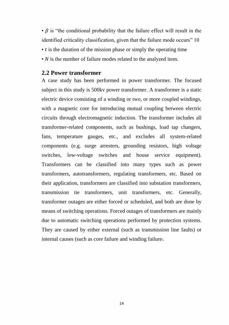
• 𝛽 is “the conditional probability that the failure effect will result in the
identified criticality classification, given that the failure mode occurs” 10
• 𝑡 is the duration of the mission phase or simply the operating time
• 𝑁 is the number of failure modes related to the analyzed item.
2.2 Power transformer
A case study has been performed in power transformer. The focused
subject in this study is 500kv power transformer. A transformer is a static
electric device consisting of a winding or two, or more coupled windings,
with a magnetic core for introducing mutual coupling between electric
circuits through electromagnetic induction. The transformer includes all
transformer-related components, such as bushings, load tap changers,
fans, temperature gauges, etc., and excludes all system-related
components (e.g. surge arresters, grounding resistors, high voltage
switches, low-voltage switches and house service equipment).
Transformers can be classified into many types such as power
transformers, autotransformers, regulating transformers, etc. Based on
their application, transformers are classified into substation transformers,
transmission tie transformers, unit transformers, etc. Generally,
transformer outages are either forced or scheduled, and both are done by
means of switching operations. Forced outages of transformers are mainly
due to automatic switching operations performed by protection systems.
They are caused by either external (such as transmission line faults) or
internal causes (such as core failure and winding failure

15
2.2.1-Transformer Construction
Basically a transformer consists of two inductive windings and a
laminated steel core. The coils are insulated from each other as well as
from the steel core. A transformer may also consist of a container for
winding and core assembly (called as tank), suitable bushings to take the
terminals, oil conservator to provide oil in the transformer tank for
cooling purposes. The figure1 illustrate the basic construction of a
transformer.
Fig 2.1- Basic construction of transformer
2.2.2- Some major and minor causes of power transformer
outages
Transformers are critical links in power systems, and can take a long time
to replace if they fail. Through faults cause extreme physical stress on
transformer windings, and are the major cause of transformer failures.
When a transformer becomes hot, the insulation on the windings slowly
breaks down and becomes brittle over time.

16
Fig 2.2- Power transformer failure
There is almost twice the moisture near bottom as there is at the top. So,
this transformer failed in the lower one-third of the windings due to paper
insulation breakdown Fig 2.3.
Fig 2.3- Failure due to moisture content in oil
Lightning strike occurs when the voltage generated between a cloud and
the ground exceeds the dielectric strength of the air Fig 2.4.

17
Fig 2.4- Lightning strike – transmission tower
Birds are the most common cause of animal faults on both transmission
systems and insulated substations. Nesting birds commonly build their
homes on transmission towers and in substation. Nesting materials can
cause faults.
Fig 2.5- Bird nest on the transmission system

18
2.3- Related Studies In the literature, the publication on the applications of FMECA for the
past five years are considered and it have been applied in different field
and scope of problems.
2.3.1- Study (1):
Title:
Reliability analysis of metro door system based on FMECA
Author/s:
Xiaoging Cheng
Date:
2013
Scope of the project:
The FMECA method is applied to the door system of metro train. The
FMECA analysis is carried out on the several key components which
have a high failure rate, so the failure modes which have a great effect on
the door system are obtained and auxiliary decision-making reference
could be provided for maintenance of door system.
Project Conclusion and result:
Through statistical analysis of defective components of metro door
system. The FMECA method is utilized to analyze four components
which have a high failure rate. The results show that the EDCU function
failure and the breakage of limit switch s1 are the weakness of door
system, and should be concerned in the maintenance operation.

19
2.3.2- Study (2):
Title:
Study of centrifugal pump using FMECA analysis based on cost
estimation
Author/s:
Deeptesh Singh, Amit Suhane
Date:
2013
Scope of the Project:
This project presents the generic process of FMECA for centrifugal pump
failures and a case study on centrifugal pump failure cost estimation
actual and after implementation of optimum strategies of maintenance.
Project Conclusion and Results:
1- The cost based FMECA presents graphic representation , and
provides an efficient classification of failure based on faults
priority and economic profit.
2- To select the best mix of failures to be repaired and this type of
problem is easily resolvable through priority of critical index of
components and diagnose them appropriate maintenance strategies.
3- Enhance the profit with 36.74% overall (including labor, downtime
and spare parts cost only) per year by proper selection of
maintenance strategies with the help of FMECA

20
2.3.3- Study (3):
Title:
Reliability Analysis of Aircraft Equipment Based on FMECA Method
Author/s:
Li Jun, Xu Huibin
Date:
2012
Scope of the project:
FMECA is applied in an aircraft equipment to analyze its reliability and
improve operational reliability of the product.
Project Conclusion and Results:
This project conducts the reliability modeling of aircraft equipment and
predicts its MTBF. In order to analyze and improve its reliability,
reliability technique FMECA method is used to analyze its failure models
and destructive degree, thus propose content, key point and method
which be pay attention to while using and maintaining the equipment.
The result shows that reliability analysis and the application of FMECA
method prolong the life span of this equipment and improves the
operational reliability greatly, thus proves that it is correct to apply this
method to reliability analysis and improvement of operational reliability
of a product. In mean time, it may help to improve the reliability of other
aviation products.

21
2.3.4- Study (4):
Title:
Safety Analysis of Airborne Weather Radar Based on FMECA Analysis
Author/s:
MA Cunbao, GAO Zi, Yang Lin
Date:
2011
Scope of Project:
The safety of the airborne weather radar (WXR) will directly affect the
safety of the whole aircraft and the flight. Taken the WXR as an
illustrative system , the FMECA method in the safety analysis of system
investigated in this project.
Project Conclusion and Results:
Based on the typical fault of WXR, the FMECA method of system safety
analysis is studied. This project calculated the criticality of the failure
modes , drawn criticality matrix , classified the failure mode, and rank the
failure mode in order of criticality.
All the above studies focused on the analyzing failure modes, failure
causes, and their effects and rank this failure according to their priorities.
Improve reliability and reduce risks by reducing severity and occurrence.
But they tend to use quantitative analysis rather than qualitative analysis.
In this research I used qualitative analysis, because failure rates for power
transformer are not available to calculate critical index.

22
CHAPTER THRE
METHODOLOGY

23
Chapter Three: Methodology
3.1-Analysis Methodology
This project methodology requires gathering relevant data about 500kv
transformer from the central workshop in Khartoum bahary, which will
be used to analyze potential failure modes, possible causes, and their
local and final effects and rank according to risk priority number.
Generally, there are two parts to be completed in performing the
FMECA. The first part is to perform the failure modes and effect analysis
(FMEA). The second part is to classify the failure mode according to the
severity and probability of occurrence for the criticality analysis (CA).
Also, in details there are several steps into performing the FMECA
applied herein [1][2][3]:
Fig 3.1- Systematic procedures to create FMECA
System Definition
Failure mode identification
Determination of the failure causes
Assessment of failure effects
Classification of severity
Estimation of probability of occurrence
Probability of Detection
Perform Criticality Analysis
Compensating provision

24
System Definition
System definition provides the transformer and transformer
components functions and features, such as performance, interface,
monitoring, . This is a precursor to the FMECA process.
Failure mode identification
Here, all failure modes data are determined based on the
computerize failure record system. The main focus will be the major
component failures with highest frequencies or the number of occurrence.
This step must be through because this information will feed into the risk
ranking for each of the failures.
Determination of the failure causes
Based on the record data, the major components failures are
coming from the highest frequencies of occurrence. In order to find the
failure causes, a study has been conducted at the transformer with help
from the engineering personnel and process specialist.
It is based on their intuitive and judgment through experiences and
expertise of what are the failure modes, how the failure occur, why the
failure happen in the first place from a discussion and brainstorming
session.
Assessment of failure effects
It is a step whereby measurements of how the failure will influence
the transformer components performances is determine whether the
failure will cause a complete system failure, partial degradation or there is
actually no impact at all to the power transformer performance. It is
actually a continuity of discussion and brainstorming step from the
previous step 3 activities.

25
Classification of severity
It is a determination step of how serious the effects identified in
step 4 would be if a given failure occurs. There could be other factors to
consider that contributes to the overall severity of the each of the failures.
Each effect is given a severity numbers from 1 (no danger) to 10
(critical).
These numbers help to prioritize the failure modes and their
effects. If the sensitivity of an effect has a number 9 or 10, action is
considered to change by eliminating the failure mode, if possible.
Estimation of probability of occurrence
In this step, it is necessary to look at the number of times a failure
occurs. For the purpose of the case study, it is based on the actual figures
of the failures frequencies collected from the power transformer system.
In general, a failure mode is given an occurrence ranking, 1 (no
occurrence) to 10 (high occurrence). If the occurrence is high, meaning
more than 4 for non-safety, failure modes actions are to be determined.
Probability of Detection
The Detection Rating is the numerical estimate of the probability
of Detecting a failure mode arising from a particular cause such that the
effect of failure is prevented. A scale of 1 to 10 is used in which 1
indicates that detection is highly likely and 10 almost impossible.
Perform Criticality Analysis
A procedure by which each potential failure mode is ranked
according to the combined influence of severity, and probability.
Qualitative analysis:
Used when specified power transformer failure rates are not
available.

26
Quantitative analysis:
Used when sufficient failure rate data is available to calculate
criticality numbers.
In this project I used qualitative analysis (severity*occurrence),
because transformer failure rates are not available to compute criticality
numbers.
compensating provision
Identify the corrective action that need to be taken in order to
eliminate or mitigate the risk and then follow up on the completion of
those recommended actions. Here it is important to focus on the removing
of the failure cause, decreasing the probability of the occurrence and
reducing the severity of the failure.
3.2- How to Evaluate Risk Priority Number (RPN)?
A FMECA can be performed to identify the potential failure modes
for a power transformer. The RPN method then requires the analysis team
to use past experience and engineering judgment to rate each potential
problem according to three ratings:
Severity(S), which rates the severity of the potential effect of the
failure.
Occurrence (O), which rates the likelihood that the failure will
occur.
Detection (D), which rates the likelihood that the problem will be
detected.
RPN = Severity*Occurrence*Detection
CA = Severity*Occurrence

27
TABLE 3.1. Evaluation criteria for severity, occurrence and detection
Severity(S) Occurrence(O) Detection(D) Ranking
No effect Failure is unlikely Almost certain 1
Very minor Very high 2
Minor high 3
Very low Moderate high 4
Low Moderate 5
Moderate Moderate:
Occasional failures
Low 6
High High Very low 7
Very high High:
Repeated failures
Remote 8
Hazardous with
warning
Very high Very remote 9
Hazardous without
warning
Very high:
Failure is almost
unavoidable
Absolutely uncertain 10

28
CHAPTER FOUR
Results and
Discussion

29
Chapter Four: Results and Discussion
4.1- Power Transformer Components
To completely analyze failures of a transformer it should be broken to
subsystem, component and parts. In this research, 500kv power
transformers considered to study under FMECA technique. Different
components of a power transformer are [5]:
4.1.1- Core
The function of core is to concentrate magnetic flux.
4.1.2- Tank
The tank is primarily the container for the oil and a physical
protection for the active part. It also serves as support structure for
accessories and control equipment.
The tank has to withstand environmental stresses, such as
corrosive atmosphere, high humidity and sun radiation.
4.1.3- Windings
The function of the windings is to carry current. In addition to
dielectric stresses and thermal requirements the windings have to
withstand mechanical forces that may cause windings replacement.
4.1.4- Bushings
A bushing is a component that insulates a high voltage conductor
passing through a metal enclosure, i.e. a current path through the tank
wall. The inside of the bushing may contain paper insulation and the
bushing is often filled with oil to provide additional insulation.
4.1.5-Tap changer
The On-Load Tap-Changer (OLTC) is the most complex
component of the transformer and its function is to regulate the voltage
level by adding or subtracting turns from the transformer windings.
The OLTC is built in two separate sections; the diverter switch
and the tap selector. Due to the fact an interrupting of the supply is

30
unacceptable for a power transformer, these are fitted with a complex
mechanism that change turns ratio without interrupting the load current.
4.1.6- Insulation system
The insulation system in a transformer consists of two
parts, a solid part (cellulose) and a liquid part (transformer
oil), and where the liquid part has a double function.
Solid insulation
The solid insulation in a transformer is cellulose based products such as
press board and paper. Its main function is to isolate the windings.
Transformer oil
The oil serves as both cooling medium and as part of the insulation
system. The quality of the oil greatly affects the insulation and cooling
properties of the transformer.
There are two kinds of failure sources of transformer outages [6].
Major failures those that are severe and require the removal of
transformer to be reprocessed under factory conditions or its replacement.
Minor failures can repair on site as shown on table 4.1.

31
TABLE 4.1. Transformer outage causes
Failure Outage causes
Minor
Outage category
Electrical outage
Mechanical
outages
Environmental
outages
Others outage
Major
4.2 FMECA for 500kv transformers
FMECA should include a list of transformer failure, reasons of
these failures, local effects that refer to the consequences of each possible
failure on the transformer elements, final effects that describe the impact
of those possible failures on the whole transformer, an alternative
provision or recommended actions to avoid these failures. Finally, a
criticality analysis (CA) allowing assigning a Risk Priority Number
(RPN) to each failure mode must be done.
RPN = S*O*D

32
The FMECA of Components minor and major failures of power
transformer are estimated in table 3 and table 4 respectively. In these
tables attention is given to all possible major and minor failures that
might result interruption of transformer service. The impact of minor
failures is not significant on transformer life. Therefore, the final effects
of minor failures are interpreted in terms of repair time duration.
However, the frequent over current outages in the long run, resulting
from overloading, lead to insulation degradation over time. As, reported
in table 3 over current outage scores the highest RPN.
On other hand, earth fault and differential protection have the same
RPN. Their occurrences represent a hazard for the transformer operation.
Table 4 assigned highest RPN in transformer major failures to insulation
system and on-load tap changer respectively. Insulation system is an
irreversible phenomena associated with transformers in service that result
from oxygen, moisture and temperature. Tap changer is the only
moveable element in the transformer, and had been a prone to range of
failures associated with the switching contacts and drive mechanism [7].
Therefore, the condition of the top changer oil and its contacts resistance
are the most encountered problem to power utilities.
Core and windings failures are the most catastrophic scenarios of
transformer outages, they require an immediate replacement of the
transformer and, in case a spare transformer is not directly available,
additional costs for not delivered power and penalty costs should also be
considered. The frequency of their occurrence is very low but their
impact on the network operation is extremely high.

33
TABLE 4.2. Minor Failures FMECA of Transformer
Failure
Outage
mode
Possible
outage
cause
Local effect
Final effect
Compensating
provision
S
O
D
RPN
Minor
B&P
5
5
2
50
OC
6
6
2
72
EFP
5
4
3
60
DP
5
4
3
60
OI
6
4
2
48
B&D
7
3
2
42
FFS
2
3
3
18
Leakage
2
4
3
24
BW
4
3
2
24

34
A&B
4
3
2
24
HM
7
3
2
42
NF
3
3
4
36
Others
3
5
3
45

35
TABLE 4.3. Major Failures FMECA of Transformer
Failure
Outage
(Failure)
mode
Possible
outage causes
Local effect
Final effect
Compensating
provision
S
O
D
RPN
Major
7
4
7
196
9
2
9
162
9
2
9
162
Bushing
replacement
6
2
7
84
9
2
3
54
8
4
8
256

36
CHAPTER FIVE
Conclusion and
Recommendation

37
Chapter Five: Conclusion and Recommendation
Conclusion
The aim of presenting a FMECA on a power transformer is to analyzing
potential failure modes, possible causes, their effects and find risk priority
number and rank according to their priority and improve reliability
through. A step by step approach of the FMECA has provide a sequential
results of the failure modes identification, failure causes and assessment
of local and final effects.
FMECA risk priority number depends on many factors and varies
according to the operating and environmental condition of power
transformer. With the application of the FMECA, a clear and systematic
failure data analysis of the power transformer components has been
presented which highlighting the major and minor components failures of
the transformer.
Recommendation
I recommend through:
1-Periodic preventive maintenance, perform some analysis like dissolved
gas analysis, systems monitoring and periodic inspection power
transformer to reduce failures.
2-following up safety rules for operators to avoid human mistakes
3-Also, these results significantly help the related engineering team to
focus the improvement of transformer performance for the right problems
at the right places.

38
References: 1-MIL-STD-1629A, Procedures for performing a Failure Mode, Effects,
and Criticality Analysis, DEPARTMENT OF DEFENSE, Washington,
DC 20301.
2-"Department of the Army, TM 5-698-4, Failure Modes, Effects and
Criticality Analysis (FMECA) for Command, Control, Communications,
Computer, Intelligence, Surveillance, and Reconnaissance (C4ISR)
Facilities, 29 September 2006."
3- Robert Borgovini, Stephen Pemberton, Michael Rossi, Failure Mode,
Effects and Criticality Analysis (FMECA), April1993.
4- Gregory Chandler, William K. Denson, Michael J. Rossi, Richard
Wanner, Failure Mode/Mechanism Distributions, September 1994
5-Sabina Karlsson, a review of life time assessment of transformers and
the use of dissolved gas analysis, 2007/2006
6-William H. Bartley P.E., failure analysis of transformers, 2000
7- RELIABILITY OF MAIN TRANSFORMERS,
Germany,( Vol.2) 2011, March.

4