Failure Analysis of the Guide Vanes of the Pico Power ...
10
1 Failure Analysis of the Guide Vanes of the Pico Power Plant Wells Turbine Mário Vieira Instituto Superior Técnico, Universidade de Lisboa, Portugal Abstract The working principle of the Wells turbine, used in the ocean energy extraction, can sometimes lead to stall in the turbine and stators’ blades, which represents an unintended action as it creates potentially damaging conditions to the mechanical components, plus reducing the efficiency of the take-off system. This work focuses on the cracking damage caused to the guide vanes of the Pico Island Wave Power Plant due to the loading from turbulent air flow and consequent vibrations, as a result of turbine stall. Comprehensive analysis of the design and manufacturing phases, as well as to the constitutive metal properties (AISI 316L stainless steel), including the consequences of welding, were carried out. Modal testing of the blades was performed. Strain gauges and pressure sensors were used to evaluate the loading profile in real-sea working conditions and different suggestions were made in order to postpone and prevent crack nucleation and propagation. The appearance of cracks seems to have been caused by mistakes taken at both design and manufacturing phases, eliminating from the guide vanes the ability to endure the aggressive loads which they were subjected to. The lack of an active control strategy on the power plant resulted in consistent turbine stall, thus contributing to the excessive loadings subjected to the blades. Keywords Wave energy, Wells turbine, Failure Analysis, Instrumentation 1. Introduction The Pico Power Plant (Figure 1) is one of the few full scale, grid connected, wave energy converters (WEC) in the world. It is a shore mounted oscillating water column type WEC located on the Portuguese island of Pico in the Azores archipelago. The plant has a chamber with a submerged opening to incident waves. The oscillation of the water surface from wave action acts as a piston to compress and expand air in the chamber, creating a bi-directional flow through a duct driving a Wells turbine connected to a generator. A Wells turbine is used because the lifting force on the turbine blades is in the same direction regardless of the air flow direction, and for its comparative simplicity compared to variable pitch turbines. However, one limitation of the Wells turbine is the stall effect. The relative angle of attack of the blades concerning the driving air flow is the vector product of both the velocity of the blades and the velocity of the driving air flow. When the relative angle of attack reaches a critical threshold the boundary layer separates from the blade surface leading to a loss of lift and increased drag. When this occurs the turbine is classified as being in a stall phase. This stall effect causes high levels of vibrations and substantial noise, which has both accelerated mechanical fatigue and environmental impact, implications, plus limiting the upper level of the pneumatic to mechanical power transfer. Turbine stall can be avoided through the implementation of an active control strategy, which aims to maintain the operation conditions in the pretended range, outside of stalling conditions. This can be Figure 1 - The Pico Island Power Plant being hit by a massive wave.
Transcript of Failure Analysis of the Guide Vanes of the Pico Power ...

1
Failure Analysis of the Guide Vanes of the Pico Power Plant Wells Turbine
Mário Vieira
Instituto Superior Técnico, Universidade de Lisboa, Portugal
Abstract
The working principle of the Wells turbine, used in the ocean energy extraction, can sometimes lead to stall in the turbine and stators’ blades, which represents an unintended action as it creates potentially damaging conditions to the mechanical components, plus reducing the efficiency of the take-off system. This work focuses on the cracking damage caused to the guide vanes of the Pico Island Wave Power Plant due to the loading from turbulent air flow and consequent vibrations, as a result of turbine stall. Comprehensive analysis of the design and manufacturing phases, as well as to the constitutive metal properties (AISI 316L stainless steel), including the consequences of welding, were carried out. Modal testing of the blades was performed. Strain gauges and pressure sensors were used to evaluate the loading profile in real-sea working conditions and different suggestions were made in order to postpone and prevent crack nucleation and propagation. The appearance of cracks seems to have been caused by mistakes taken at both design and manufacturing phases, eliminating from the guide vanes the ability to endure the aggressive loads which they were subjected to. The lack of an active control strategy on the power plant resulted in consistent turbine stall, thus contributing to the excessive loadings subjected to the blades.
Keywords
Wave energy, Wells turbine, Failure Analysis, Instrumentation
1. Introduction
The Pico Power Plant (Figure 1) is one of the few full scale, grid connected, wave energy converters (WEC) in the world. It is a shore mounted oscillating water column type WEC located on the Portuguese island of Pico in the Azores archipelago. The plant has a chamber with a submerged opening to incident waves. The oscillation of the water surface from wave action acts as a piston to compress and expand air in the chamber, creating a bi-directional flow through a duct driving a Wells turbine connected to a generator. A Wells turbine is used because the lifting force on the turbine blades is in the same direction regardless of the air flow direction, and for its comparative simplicity compared to variable pitch turbines. However, one limitation of the Wells turbine is the stall effect. The relative angle of attack of the blades concerning the driving air flow is the vector product of both the velocity of the blades and the velocity of the driving air flow. When the relative angle of attack reaches a critical threshold the boundary layer separates from the blade surface leading to a loss of lift and increased drag. When this occurs the turbine is classified as being in a stall phase. This stall effect causes high levels of vibrations and substantial noise, which has both accelerated mechanical fatigue and environmental impact, implications, plus limiting the upper level of the pneumatic to mechanical power transfer. Turbine stall can be avoided through the implementation of an active control strategy, which aims to maintain the operation conditions in the pretended range, outside of stalling conditions. This can be
Figure 1 - The Pico Island Power Plant being hit by a massive wave.
2
Figure 2 - CAD scheme of both the stators, with the turbine in the middle (A) and general dimensions (in millimeters) of the earth-side stator (B).
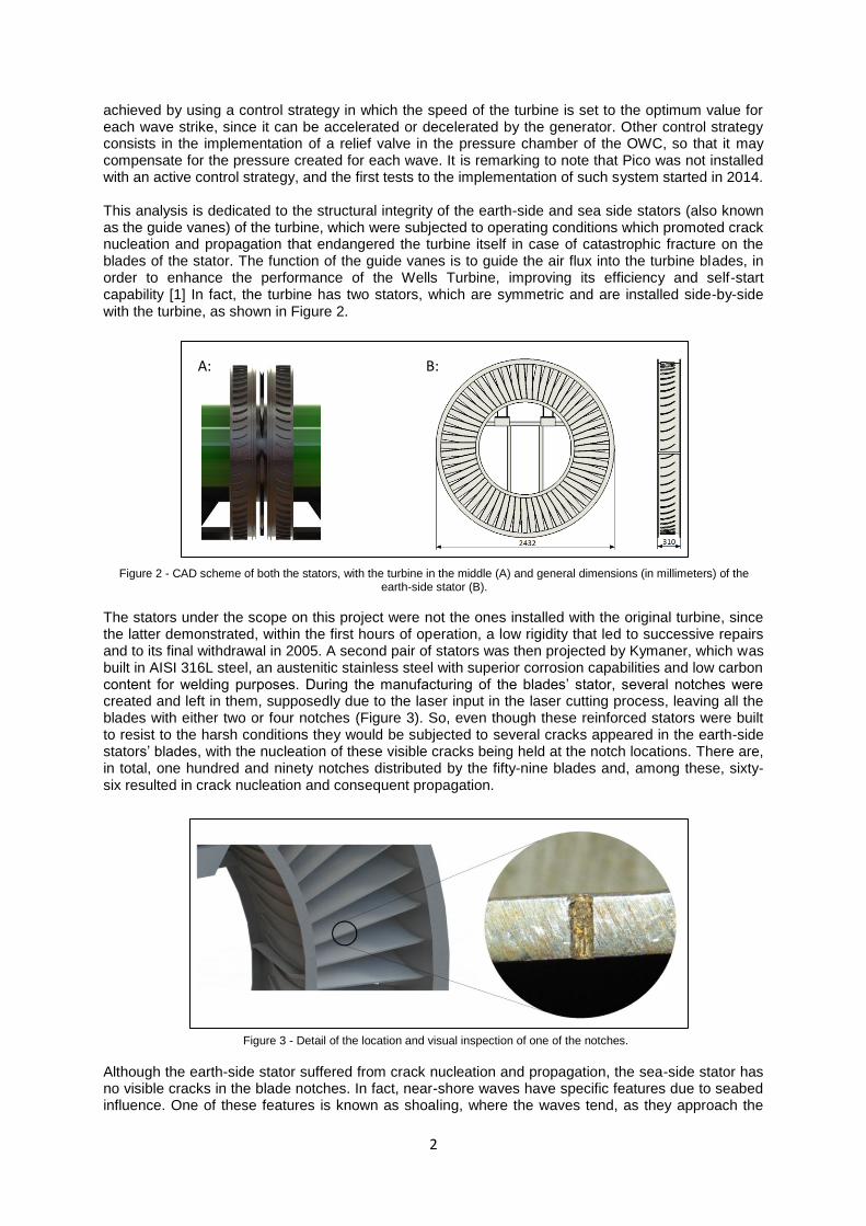
Figure 3 - Detail of the location and visual inspection of one of the notches.
achieved by using a control strategy in which the speed of the turbine is set to the optimum value for each wave strike, since it can be accelerated or decelerated by the generator. Other control strategy consists in the implementation of a relief valve in the pressure chamber of the OWC, so that it may compensate for the pressure created for each wave. It is remarking to note that Pico was not installed with an active control strategy, and the first tests to the implementation of such system started in 2014. This analysis is dedicated to the structural integrity of the earth-side and sea side stators (also known as the guide vanes) of the turbine, which were subjected to operating conditions which promoted crack nucleation and propagation that endangered the turbine itself in case of catastrophic fracture on the blades of the stator. The function of the guide vanes is to guide the air flux into the turbine blades, in order to enhance the performance of the Wells Turbine, improving its efficiency and self-start capability [1] In fact, the turbine has two stators, which are symmetric and are installed side-by-side with the turbine, as shown in Figure 2.
The stators under the scope on this project were not the ones installed with the original turbine, since the latter demonstrated, within the first hours of operation, a low rigidity that led to successive repairs and to its final withdrawal in 2005. A second pair of stators was then projected by Kymaner, which was built in AISI 316L steel, an austenitic stainless steel with superior corrosion capabilities and low carbon content for welding purposes. During the manufacturing of the blades’ stator, several notches were created and left in them, supposedly due to the laser input in the laser cutting process, leaving all the blades with either two or four notches (Figure 3). So, even though these reinforced stators were built to resist to the harsh conditions they would be subjected to several cracks appeared in the earth-side stators’ blades, with the nucleation of these visible cracks being held at the notch locations. There are, in total, one hundred and ninety notches distributed by the fifty-nine blades and, among these, sixty-six resulted in crack nucleation and consequent propagation.
Although the earth-side stator suffered from crack nucleation and propagation, the sea-side stator has no visible cracks in the blade notches. In fact, near-shore waves have specific features due to seabed influence. One of these features is known as shoaling, where the waves tend, as they approach the
A: B:
3
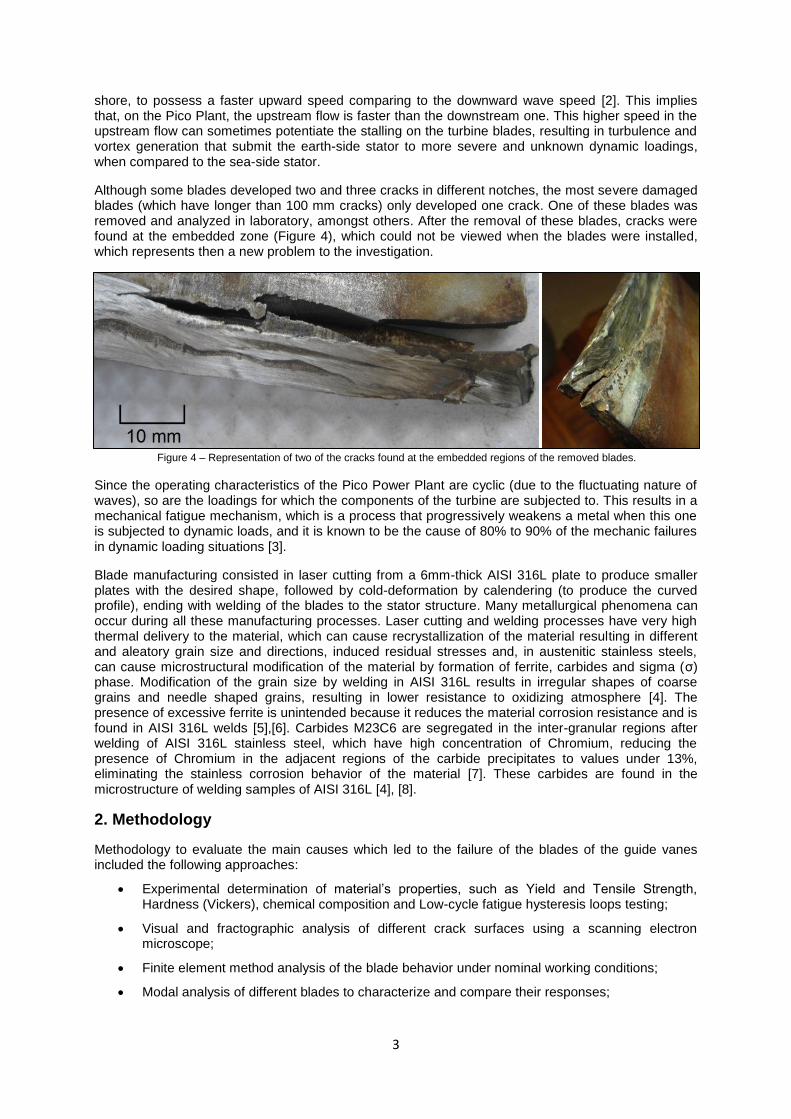
Figure 4 – Representation of two of the cracks found at the embedded regions of the removed blades.
shore, to possess a faster upward speed comparing to the downward wave speed [2]. This implies that, on the Pico Plant, the upstream flow is faster than the downstream one. This higher speed in the upstream flow can sometimes potentiate the stalling on the turbine blades, resulting in turbulence and vortex generation that submit the earth-side stator to more severe and unknown dynamic loadings, when compared to the sea-side stator.
Although some blades developed two and three cracks in different notches, the most severe damaged blades (which have longer than 100 mm cracks) only developed one crack. One of these blades was removed and analyzed in laboratory, amongst others. After the removal of these blades, cracks were found at the embedded zone (Figure 4), which could not be viewed when the blades were installed, which represents then a new problem to the investigation.
Since the operating characteristics of the Pico Power Plant are cyclic (due to the fluctuating nature of waves), so are the loadings for which the components of the turbine are subjected to. This results in a mechanical fatigue mechanism, which is a process that progressively weakens a metal when this one is subjected to dynamic loads, and it is known to be the cause of 80% to 90% of the mechanic failures in dynamic loading situations [3].
Blade manufacturing consisted in laser cutting from a 6mm-thick AISI 316L plate to produce smaller plates with the desired shape, followed by cold-deformation by calendering (to produce the curved profile), ending with welding of the blades to the stator structure. Many metallurgical phenomena can occur during all these manufacturing processes. Laser cutting and welding processes have very high thermal delivery to the material, which can cause recrystallization of the material resulting in different and aleatory grain size and directions, induced residual stresses and, in austenitic stainless steels, can cause microstructural modification of the material by formation of ferrite, carbides and sigma (σ) phase. Modification of the grain size by welding in AISI 316L results in irregular shapes of coarse grains and needle shaped grains, resulting in lower resistance to oxidizing atmosphere [4]. The presence of excessive ferrite is unintended because it reduces the material corrosion resistance and is found in AISI 316L welds [5],[6]. Carbides M23C6 are segregated in the inter-granular regions after welding of AISI 316L stainless steel, which have high concentration of Chromium, reducing the presence of Chromium in the adjacent regions of the carbide precipitates to values under 13%, eliminating the stainless corrosion behavior of the material [7]. These carbides are found in the microstructure of welding samples of AISI 316L [4], [8].
2. Methodology
Methodology to evaluate the main causes which led to the failure of the blades of the guide vanes included the following approaches:
Experimental determination of material’s properties, such as Yield and Tensile Strength, Hardness (Vickers), chemical composition and Low-cycle fatigue hysteresis loops testing;
Visual and fractographic analysis of different crack surfaces using a scanning electron microscope;
Finite element method analysis of the blade behavior under nominal working conditions;
Modal analysis of different blades to characterize and compare their responses;

4
Table 1 – Composition of the AISI 316L of the blades.
Strain analysis under operation conditions of the blades, as to understand the pattern of the loading subjected to them;
Pressure analysis to understand the pressure variation over the blade surfaces;
Metallurgical analyzes of the base material, weld material and laser cut material.
To understand the properties of the material and analyze the crack surfaces are two crucial steps while developing a failure analysis, allowing for initial understanding of the failure mechanisms.
Tension, Hardness and Strain-controlled fatigue testing was made, following their ASTM Standards. Chemical Composition was evaluated by the Atomic Emission Spectrometry technique.
Based on the commercial Finite Element Method Software ANSYS (Workbench environment), several analyzes were made in order to understand the loading distribution along the blades. The pressure loading (which is applied in the upper blade surface) was based on the most aggressive flow condition registered in the Power Plant data acquisition system.
Since the Pico Power Plant is a machine in which its intrinsic operational behavior results in the excitation of different frequencies, it became essential to comprehend the modal response of the blades while subjected to controlled force conditions, allowing for the calculation of their transfer functions and natural frequencies.
Metallurgical analyzes were made using Glyceregia reagent and an optical microscope.
Strain analysis represents one of the most important stages of this investigation: besides allowing to understand the maximum stresses dealt by the material, its high frequency operating capability makes it possible to build, based on these results, the frequency spectrum of the strain responses, which can then be compared with the results obtained from the modal analyzes. Four strain gages were installed in total, two on a blade of the earth-side and two on a blade of the sea-side, in order to understand the difference between the loadings submitted to each stator.
Analysis of the pressure variation may give understanding about how the flow progresses over the blade. Five pressure sensors were embedded in the blade and installed in the turbine, thus providing further information about the unknown air flow which strikes these blades.
3. Results
Material properties
Evaluation of the composition of the material confirmed the presence of an AISI 316L steel (Table 1) and tension testing allowed for the determination of important parameters (Table 2):
Hardness was measured and the base metal has an average of 152 HV.
Table 2 – Mechanical Properties of the AISI 316L.

5
Fractographic analysis
Three fracture surface specimens were analyzed with optical and scanning electron microscope devices, in order to understand the different origins of the developed crack. Several beach marks, which are typical of crack growth during fatigue, are observable.
Scanning electron microscope results for this surface are presented below (Figure 5):
The results for the second and third crack surfaces are presented below (Figure 6 and 7):
Figure 5: SEM images obtained from the analysis of the first fracture surface. At left: Magnified image with ratchet marks which suggest different crack nucleations in the region.
At right: Close view of the beach marks in the surface.
Figure 6: SEM images obtained from the analysis of the second fracture surface. At top, left: Magnified image with ratchet marks which suggest different crack nucleations and high stresses in the region.
At top, right: Global view of the beach marks in the surface. At bottom, left: Close view of small cracks in the beginning of the propagation phase.
At bottom, right: Detail of surface cracks initiated near beach marks.

6
122
223 265 520 715
912
0,001
0,01
0,1
1
10
100
1000
0 100 200 300 400 500 600 700 800 900 1000
(m/s
2)/
N
Frequency (Hz)
Modal analysis
Modal testing revealed the structural curve of different blades, allowing the knowledge of their natural frequencies, as well as the understanding of the effect of cracks on the blade natural frequencies. In Figure 8 it is possible to analyze one of these curves, obtained from a free-crack blade (at least, on the notch regions).
Finite Element Analysis Finite element analysis performed in ANSYS Workbench was made in order to understand, with a constant load which could simulate the most severe conditions on the turbine, what the stress (Von-Mises Equivalent Stress) distribution along the blade is like. Nevertheless, this analysis is purely static and does not simulate neither the real condition cyclic loading, nor the stall condition created by the turbine. In order to simulate these effects, Computational Fluid Dynamics (CFD) analyzes should be made to the working condition of the plant. The results indicate a maximum Von Mises stress of 5.3 MPa on the embedded region of the blade (Figure 9 on the right) and 1.54 MPa on the notch.
Figure 7: SEM images obtained from the analysis of the third fracture surface. At left: Global view of the beach marks in the surface.
At right: Magnified image of crevice corrosion-like defect, with multiple cracks in the material surface.
Figure 8 – Transfer function obtained from modal testing of one of the eart-side stator blades.

7
Figure 10 – Characteristic pattern of the effect of stall on the strain response of the blades (on the left), frequency spectrum one of these stall events (on the right)
Strain Gauge Analysis Strain gauge analysis is essential for the understanding of the response of the blade to the loadings due to the plant operation. In fact, the effect of the stall events on the blades could not be fully evaluated with the theoretical loading calculated before, since it results in unknown flow conditions. The results indicated that, besides stalling events, the stresses on the blades are very low. On the other hand, the stall induces, in each event, a severe vibration pattern on the time-based acquired data (Figure 10, on the left). Since the used strain gage is a rosette with 3-axis measuring, it is possible to obtain the equivalent stress on the material. The acquisition frequency rate of the strain gauge signals was of 10 kHz, which permitted, through appliance of a Fast Fourier Transform to the signal, the attainment of the spectrum of this signal, revealing a pattern that suggests that the stalling events can result in the excitation of a frequency range that goes from 0 to 3000 Hz, at least (Figure 10 on the right). It can be seen that the obtained spectrum is quite similar to the structural curve of the blade, obtained in the model testing.
These stalling phenomena occur in both the earth-side and the sea-side stators. Nevertheless, the maximum equivalent stress registered for the earth-side blade was of 46 MPa, whilst the one for the sea side was of 24 MPa. It can then be noted that the earth-side stator is loaded with higher forces due to shoaling; as a consequence, the earth-side guide vanes are submitted to more stalling events and to stronger ones. This could explain the difference on the damage found in each stator.
Figure 9 – Geometric model used on the FEM analyzes (on the left) and detail of the embedded region of the blade (on the right).

8
Metallurgical analysis
The results of the metallurgical analysis are shown below (Figure 11), where it is notable the kerf layer due to laser cut (Figure 11, top left), the influence of welding on the recrystallization of the material (Figure 11, top right and bottom left) and a detail of the welded region (Figure 11, bottom right):
4. Rehabilitation of the stator
In order to re-install the stator in place, several actions were taken to recover the removed blades that possessed some cracks on the notch regions. Two blades were recovered by welding of the crack and two of them were recovered by the stop-drill method. These techniques, known for their capability to raise the life of cracked components, can then be tested in real operation conditions and checked for their appliance in this specific case.
One blade was installed following a new design which aims to allow for fast and efficient removal and substitution of blades and, more important, to avoid crack nucleation and propagation on the embedded region. This design, based on mechanical joints (Figure 12), is welding and laser-cut free, avoiding the negative impacts these processes have on the material properties, especially on corrosion and fatigue resistance.
Figure 11 – At top, left: Kerf layer resulting from laser cut (250x); At top, right: boundary between base metal and weld metal, low etching attack (250x);
At bottom, left: boundary between base metal and weld metal, high etching attack (100x); At bottom, right: detail of the welded region (500x).

9
This design was built, installed and tested in real operating conditions and tested for its natural frequencies (Figure 13):
The results obtained are quite similar to the ones obtained for the original blade, although some natural frequencies got a bit reduced.
4. Discussion and suggestion of a new stator project
The conditions to which the blades are subjected are very hard, not only because of the high corrosion feature of the air that strikes them, but as well because of the presence of grit coming from the sea floor. The intrinsic operating conditions of the plant are cyclic, which result in cyclic loadings subjected to the guide vanes. It becomes clear that we are in presence of a fatigue corrosion condition, which is very debilitating for the material.
The original fixing method denoted some fragility, mainly because of the cracks found after the removal of different blades. On the other hand, it does not allow for fast and efficient blade replacement, thus representing a low flexibility solution.
This work allowed for the comprehension of the nature of the submitted loading to the guide vanes, especially in the stalling condition, making it clear we are in presence of an intense and random aerodynamic loading which excite a wide range of frequencies.
It is important then to design a completely new project, which should follow the suggestion made before; mechanical joints allow for fast removal and replacement of blades, thus despising the need for thermal processes that affect the microstructure of the material (Figure 14). This mechanical joint can, as well, include materials with different rigidities to modify the dynamic response of the blade.
514 208 251
654 713
922
0,001
0,01
0,1
1
10
100
1000
0 100 200 300 400 500 600 700 800 900 1000
(m/s
2 )/N
Frequency (Hz)
Figure 12 – Design of the mechanically-jointed blade.
Figure 13 – Modal testing of the mechanically-jointed blade.

10
5. Conclusions
The main conclusions (or root causes) of this investigation are the following:
The embedded region design promotes the stress concentration with an avoidable geometry, plus raising the stresses in a previously welded and laser cut region. Considering that the environment is extremely corrosive and the loadings are cyclic, it is not surprising the nucleation of fatigue-induced cracks in these regions;
The notches left by the laser-cut procedures on the blades promoted the nucleation of several cracks on them; these notches promote the stress concentration and have low surface quality, thus promoting corrosion on their surfaces.
The absence of an active control strategy on the Wells Turbine of the Pico Power Plant potentiates the occurrence of stall events, which are quite common. This results in excessive loadings on the components of the turbine, especially on the guide vanes.
References
[1] Suzuki, M. (2006). “Design Method of Guide Vane for Wells Turbine”, J. of Thermal Science Vol.15, No.2 [2] Brooke, J.(2003).“Wave Energy Conversion”, Elsevier Ocean Engineering Book Series, Vol.6 [3] Branco, C. M. (2011), “Mecânica dos Materiais”, Fundação Calouste Gulbenkian [4] Samanta, S. K. et al. (2006), “Effect of rare earth elements on microstructure and oxidation behavior in TIG weldments of AISI 316L stainless steel” [5] Dadfar, M. et al. (2007),“Effect of TIG welding on corrosion behavior of 316L stainless steel”, Materials Letters [6] Collins, S. et al. (2000), “Weldability and corrosion studies of AISI 316L electropolished tubing”, Swagelok Company [7] Aydogdu, G. et al. (2006), “Determination of susceptibility to intergranular corrosion and electrochemical reactivation behaviour of AISI 316L type stainless steel”, Corrosion Science [8] Ramlee, N. et al. (2010), “Effect of Temperature and Chloride Concentrations on the Corrosion Behaviour of Welded 316L Stainless Steel”, ICFMD 2010
Figure 14 – Detail of the embedded region of the design suggestion for a new stator. Note the intermediate material between the blade and the supports, which can be made from absorbing materials to modify the dynamic response of the blade.