Failure Analysis of Single Pin Loaded E -Glass …...Page 647 Failure Analysis of Single Pin Loaded...
10
Page 647 Failure Analysis of Single Pin Loaded E-Glass Epoxy Composite Plate K. Ratnakara Rao Department of Mechanical Engineering, SISTAM College, JNTUK, India. J. Balabhaskara Rao Department of Mechanical Engineering, SISTAM College, JNTUK, India. ABSTRACT The assessment and expectation of failure probability and safe levels of composite materials is of outrageous significance as far as manufacturing and structural design. The experimental examinations portrayed in the present paper were directed to concentrate the quality and disappointment conduct of composite plate under pointed load conditions. Pin bearing tests were done on E-glass/epoxy composite plate created by hand lay-up. The analyses examined the impact of vital parameters, including example geometry and stacking sequences, on the failure qualities. Tests were performed with two different stacking sequences: [0/90/+30/-30] s and [0/90/+60/-60] s . Geometrical arrangements of examples, for example, proportion of edge distance to pin diameter (E/D) and proportion of example width to pin diameter across (W/D) were appropriately differed to watch all conceivable failure modes. A sum of 150 distinctive pin stacked composite plate examples, two laminate configurations, five edge: pin/diameter proportions, five width: pin/diameter proportions and three specimens for each condition were tried under static stacking conditions. The test estimations demonstrated that the load carrying capacity of a pin loaded hole could be changed by adjusting the example geometry and stacking sequences. In this way, the geometry of the pin connected joints was intended to attempt bearing failures as it were. Keywords: Stacking sequence, Ultimate bearing strength, Pin loaded plates, Glass/epoxy, Ansys. 1. INTRODUCTION A composite material is a mixture of twoor more distinct constituents or phases. But this definition is not sufficient and three other criteria have to be satisfied before the material can be said to be a composite. First, both constituents have to be in reasonable proportions, say greater than 5%. Secondly, it is only when the constituents phases having different properties, and hence the composite properties are noticeably different from the properties of the constituents. Thirdly, there are distinct, recognizable interfaces between the constituent phases. Depending on the properties, relative amounts, degree of bonding &orientation of various constituents along with the size, shape & distribution of discontinuous constituents, composite materials possesses characteristics properties, such as stiffness strength, weight, high temperature performance, corrosion resistance, hardness, which are not possible with the individual constituents. 2. LITERATURE SURVEY [1]Fu-Kuo Chang, Kuo-Yen Chang, “A Progressive Damage Model for Laminated Composite Containing Stress Concentrations”. [2]H. J. Lin & C. C. Tsai, “Failure Analysis Of Bolted Connections Of Composites With Drilled And Moulded-In Hole”. [3]Nahla K. Hassan, Mohamed A. Mohamdien and Sami H. Rizkalla, “Finite Element analysis of Bolted Connections for PFRP Composites”. [4]Y. Xiong and O.K. Bedair, “ Analytical and Finite Element Modeling of Riveted Lap Joints in Aircraft Structure. [5]P.P. Camanho and F.L. Matthews, “A Progressive Damage Model for Mechanically Fastened Joints in Composite Laminates”.[6]AlaattIcn Aktas,Ramazan Karakuzu, “Failure Analysis Of Two- Dimensional Carbon-Epoxy Composite Plate Pinned Joint ”.[7]Th. Kermanidis, G.
Transcript of Failure Analysis of Single Pin Loaded E -Glass …...Page 647 Failure Analysis of Single Pin Loaded...

Page 647
Failure Analysis of Single Pin Loaded E-Glass Epoxy Composite
Plate
K. Ratnakara Rao
Department of Mechanical Engineering,
SISTAM College, JNTUK, India.
J. Balabhaskara Rao
Department of Mechanical Engineering,
SISTAM College, JNTUK, India.
ABSTRACT
The assessment and expectation of failure probability
and safe levels of composite materials is of outrageous
significance as far as manufacturing and structural
design. The experimental examinations portrayed in
the present paper were directed to concentrate the
quality and disappointment conduct of composite plate
under pointed load conditions. Pin bearing tests were
done on E-glass/epoxy composite plate created by hand
lay-up. The analyses examined the impact of vital
parameters, including example geometry and stacking
sequences, on the failure qualities. Tests were
performed with two different stacking sequences:
[0/90/+30/-30]s and [0/90/+60/-60]s. Geometrical
arrangements of examples, for example, proportion of
edge distance to pin diameter (E/D) and proportion of
example width to pin diameter across (W/D) were
appropriately differed to watch all conceivable failure
modes. A sum of 150 distinctive pin stacked composite
plate examples, two laminate configurations, five edge:
pin/diameter proportions, five width: pin/diameter
proportions and three specimens for each condition
were tried under static stacking conditions. The test
estimations demonstrated that the load carrying
capacity of a pin loaded hole could be changed by
adjusting the example geometry and stacking
sequences. In this way, the geometry of the pin
connected joints was intended to attempt bearing
failures as it were.
Keywords: Stacking sequence, Ultimate bearing
strength, Pin loaded plates, Glass/epoxy, Ansys.
1. INTRODUCTION
A composite material is a mixture of twoor more distinct
constituents or phases. But this definition is not
sufficient and three other criteria have to be satisfied
before the material can be said to be a composite. First,
both constituents have to be in reasonable proportions,
say greater than 5%.
Secondly, it is only when the constituents phases having
different properties, and hence the composite properties
are noticeably different from the properties of the
constituents. Thirdly, there are distinct, recognizable
interfaces between the constituent phases.
Depending on the properties, relative amounts, degree of
bonding &orientation of various constituents along with
the size, shape & distribution of discontinuous
constituents, composite materials possesses
characteristics properties, such as stiffness strength,
weight, high temperature performance, corrosion
resistance, hardness, which are not possible with the
individual constituents.
2. LITERATURE SURVEY
[1]Fu-Kuo Chang, Kuo-Yen Chang, “A Progressive
Damage Model for Laminated Composite Containing
Stress Concentrations”. [2]H. J. Lin & C. C. Tsai,
“Failure Analysis Of Bolted Connections Of Composites
With Drilled And Moulded-In Hole”. [3]Nahla K.
Hassan, Mohamed A. Mohamdien and Sami H. Rizkalla,
“Finite Element analysis of Bolted Connections for
PFRP Composites”. [4]Y. Xiong and O.K. Bedair, “
Analytical and Finite Element Modeling of Riveted Lap
Joints in Aircraft Structure. [5]P.P. Camanho and F.L.
Matthews, “A Progressive Damage Model for
Mechanically Fastened Joints in Composite
Laminates”.[6]AlaattIcn Aktas,Ramazan Karakuzu,
“Failure Analysis Of Two- Dimensional Carbon-Epoxy
Composite Plate Pinned Joint ”.[7]Th. Kermanidis, G.

Page 648
Lebeas, K.I.Tserpes and Sp. Pentelakis, “Finite Element
Modeling Of Damage Accumulation In Bolted
Composite Joints Under Incremental Tensile
Loading”.[8]Marie-Laure Dano, Guy Gendron and
Andre Picard,” Stress And Failure Analysis Of
Mechanically Fastened Joints In Composite Laminates”.
[9]Q.M. Li, R.A.W. Mines, R.S. Birch, “Static and
Dynamic Behavior of Composite Riveted Joints In
Tension”. [10]Okenwa I. Okoli and Ainullotfi Abdul-
Latif, “Failure in Composite Laminates: Overview of an
Attempt at prediction”. [11]K.I. Tserpes, G. Labeas, P.
Papanikos and Th. Kermanidis, “Strength Prediction Of
Bolted Joints In Graphite/Epoxy Composite Laminates”.
[12]Bulent Murat Icten and Ramazan Karakuzu,”
Progressive Failure Analysis of Pin- Loaded Carbon–
Epoxy Woven Composite Plates”. [13]Buket Okutan and
Ramazan Karakuzu, “The Strength Of Pinned Joints In
Laminated Composites”. [14]B. Yang , E. Pan , F.G.
Yuan. “Three-Dimensional Stress Analyses In
Composite Laminates With A Pinned Hole”.[15]J.
Wang,P.J. Callus, M.K. Bannister,”Experimental And
Numerical Investigation Of The Tension And
Compression Strength Of Un-Notched And Notched
Quasi- Isotropic Laminates”.
3. MATERIALS AND METHODS
3.1 Materials
This chapter describes the details of processing of the
composites and the experimental procedures. The raw
materials used in this work are
E-glass Fiber mat
Epoxy Resin CY225 and
Hardener HY225
3.2 Definition of problem statement
In this study, a laminated composite plate with a single
circular hole with a pin is used. It is desired to find the
maximum failure load Pmax that can be applied before the
joint fails and the mode of failure for each geometry. Pin
strength is very high compared with that of the
composite plate. For this reason the failure of the pin has
been neglected. The geometry of the composite
specimens is shown in Fig 3.1, where L + E, W are the
length and width of the specimen, respectively. D is the
diameter of the holes. E is the distance from the free
edge to the center of the hole. Pins are located at the
centre of the holes. A uniform tensile load P is then
applied to the plate and this load is resisted by a rigid
pin. The load is parallel to the plate and is symmetric
with respect to the center line. Thus, the load cannot
create bending moments about x, y, z axes.
Fig. 3.1. The geometry of the specimen.
The ratios of E/D and W/D were changed in order to
verify their influence on the load bearing performances
and joint failure modes. In order to estimate the strength
of single pin-loaded specimens, the static bearing
strength is calculated as:
𝜎𝑏 =P
D. t
Where 𝜎𝑏 , P, D and t represent bearing strength,
maximum load, pin diameter and thickness of the
specimen, respectively.
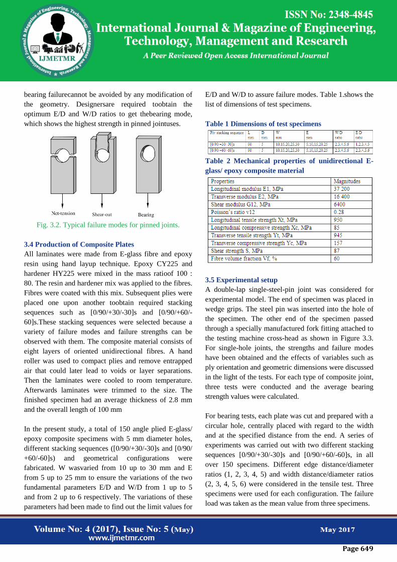
3.3 failure modes for pinned joints
The failure strength and failure mode of single-hole pin-
loaded specimens depends upon three geometric
variables: specimen width, edge distance and thickness.
In general, there are three basic pinned joint failure
modes related to composites: These are net tension,
shear out, and bearing as shown in Fig 3.2. In practice,
combinations of these failure modes are possible. Net-
tension and shear out modes are catastrophic and result
from excessive tensile and shear stresses. Bearing mode
is local failure and progressive,and related to
compressive failure. Net-tension and shear outmodes can
be avoided by increasing the end distance (E) and
width(W) of the structural part for a given thickness but
Page 649
bearing failurecannot be avoided by any modification of
the geometry. Designersare required toobtain the
optimum E/D and W/D ratios to get thebearing mode,
which shows the highest strength in pinned jointuses.
Fig. 3.2. Typical failure modes for pinned joints.
3.4 Production of Composite Plates
All laminates were made from E-glass fibre and epoxy
resin using hand layup technique. Epoxy CY225 and
hardener HY225 were mixed in the mass ratioof 100 :
80. The resin and hardener mix was applied to the fibres.
Fibres were coated with this mix. Subsequent plies were
placed one upon another toobtain required stacking
sequences such as [0/90/+30/-30]s and [0/90/+60/-
60]s.These stacking sequences were selected because a
variety of failure modes and failure strengths can be
observed with them. The composite material consists of
eight layers of oriented unidirectional fibres. A hand
roller was used to compact plies and remove entrapped
air that could later lead to voids or layer separations.
Then the laminates were cooled to room temperature.
Afterwards laminates were trimmed to the size. The
finished specimen had an average thickness of 2.8 mm
and the overall length of 100 mm
In the present study, a total of 150 angle plied E-glass/
epoxy composite specimens with 5 mm diameter holes,
different stacking sequences ([0/90/+30/-30]s and [0/90/
+60/-60]s) and geometrical configurations were
fabricated. W wasvaried from 10 up to 30 mm and E
from 5 up to 25 mm to ensure the variations of the two
fundamental parameters E/D and W/D from 1 up to 5
and from 2 up to 6 respectively. The variations of these
parameters had been made to find out the limit values for
E/D and W/D to assure failure modes. Table 1.shows the
list of dimensions of test specimens.
Table 1 Dimensions of test specimens
Table 2 Mechanical properties of unidirectional E-
glass/ epoxy composite material
3.5 Experimental setup
A double-lap single-steel-pin joint was considered for
experimental model. The end of specimen was placed in
wedge grips. The steel pin was inserted into the hole of
the specimen. The other end of the specimen passed
through a specially manufactured fork fitting attached to
the testing machine cross-head as shown in Figure 3.3.
For single-hole joints, the strengths and failure modes
have been obtained and the effects of variables such as
ply orientation and geometric dimensions were discussed
in the light of the tests. For each type of composite joint,
three tests were conducted and the average bearing
strength values were calculated.
For bearing tests, each plate was cut and prepared with a
circular hole, centrally placed with regard to the width
and at the specified distance from the end. A series of
experiments was carried out with two different stacking
sequences [0/90/+30/-30]s and [0/90/+60/-60]s, in all
over 150 specimens. Different edge distance/diameter
ratios (1, 2, 3, 4, 5) and width distance/diameter ratios
(2, 3, 4, 5, 6) were considered in the tensile test. Three
specimens were used for each configuration. The failure
load was taken as the mean value from three specimens.

Page 650
Figure 3.3. Experimental setup for pin-joint fixture.
All specimens were mounted in the testing machine
using a set of test fixture specially designed for this
experiment and loaded at a constant crosshead rate of 0.5
mm min-1
to minimize any catastrophic failure. Applied
load and pin displacement were continuously recorded
from the chart recorder attached to the testing machine
for each test. By using a load cell mounted on the testing
machine, the magnitude of the applied load was
measured. During the test, the displacement of bottom
grip was also recorded. Specimens were tested to final
failure. How failure is affected by geometry was
observed.
Photographs of different types of failure modes for E/D
and W/D series are shown in Figs 3.4. respectively.
Fig 3.4 specimens of E/D, W/D ratios of stacking
sequence of [0/90/+30/-30]s and [0/90/+60/-60]s
4. VALIDATION OF ANSYS MODEL
The present work is to find the failure strengths and
failure modes of pin loaded E Glass Epoxy composite
plates with different geometric proportions. The
variation in geometric proportions is done by varying
E/D, W/D, keeping D and T constant. All the analyses
are carried using a FEA package ANSYS16.1. For
validating the model used in ANSYS, first the analyses
are performed on pin loaded composite plates by varying
E/D and W/D keeping D and T as constant and these
results are compared with the experimental results. The
work is then extended by varying D and T. In the present
chapter validation of the ANSYS model is presented.
4.1 Geometry of the specimen
A composite rectangular plate of length L+E, width W
and thickness T is considered. A hole of diameter D is
made at a distance of E from one edge of the plate. A
rigid pin is located at the centre of the hole. The load P is
applied parallel to the plate along the longitudinal axis.
The specimen has symmetry with respect to the
longitudinal axis. Different specimens are obtained by
varying the geometric proportions of the plate. This is
done by changing E/D and W/D but keeping the
parameters D and T as constant i.e. the distance of the
hole from one edge of the plate and the width of the
specimen only vary.
Page 651
The Ansys 16.1 work bench is taken as my path of work.
The dimensions of the specimen as taking diameter 5
mm and thickness as 2.8 mm And overall length of the
specimen as 100 mm and by changing the width and
edge distance. With different ply angle orientations. And
these can be done by Ansys ACP pre tool, Ansys ACP
post and static structural
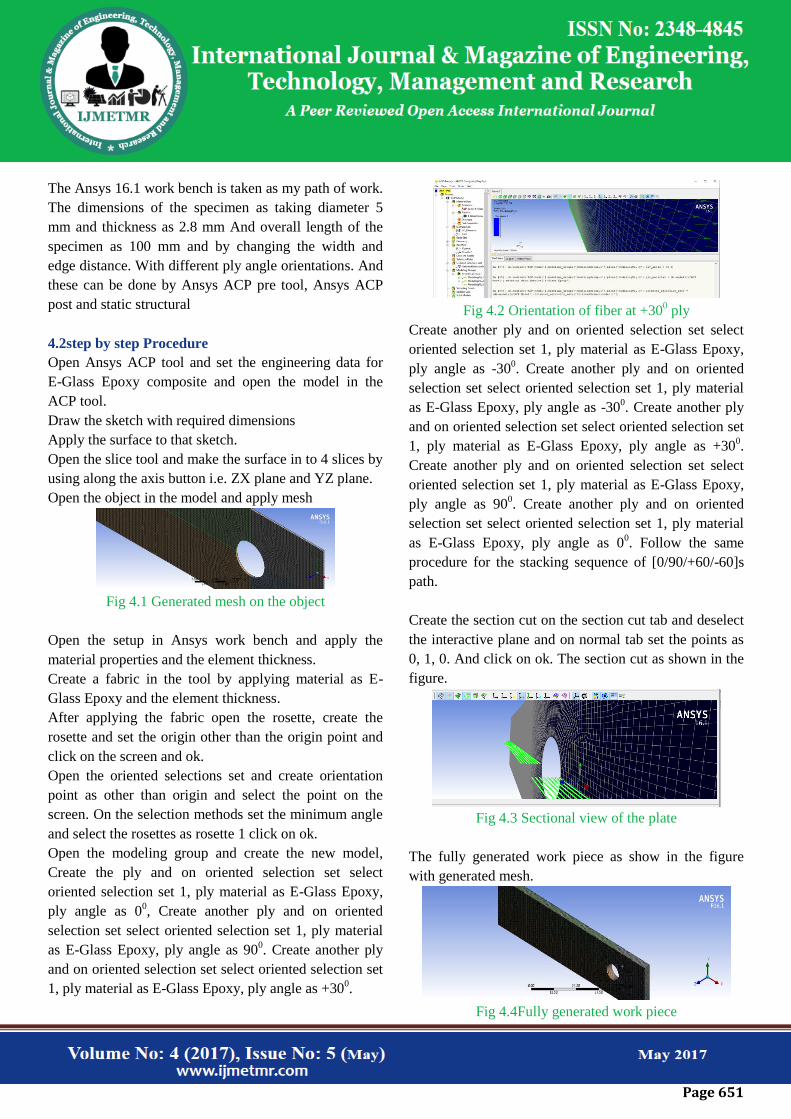
4.2step by step Procedure
Open Ansys ACP tool and set the engineering data for
E-Glass Epoxy composite and open the model in the
ACP tool.
Draw the sketch with required dimensions
Apply the surface to that sketch.
Open the slice tool and make the surface in to 4 slices by
using along the axis button i.e. ZX plane and YZ plane.
Open the object in the model and apply mesh
Fig 4.1 Generated mesh on the object
Open the setup in Ansys work bench and apply the
material properties and the element thickness.
Create a fabric in the tool by applying material as E-
Glass Epoxy and the element thickness.
After applying the fabric open the rosette, create the
rosette and set the origin other than the origin point and
click on the screen and ok.
Open the oriented selections set and create orientation
point as other than origin and select the point on the
screen. On the selection methods set the minimum angle
and select the rosettes as rosette 1 click on ok.
Open the modeling group and create the new model,
Create the ply and on oriented selection set select
oriented selection set 1, ply material as E-Glass Epoxy,
ply angle as 00, Create another ply and on oriented
selection set select oriented selection set 1, ply material
as E-Glass Epoxy, ply angle as 900. Create another ply
and on oriented selection set select oriented selection set
1, ply material as E-Glass Epoxy, ply angle as +300.
Fig 4.2 Orientation of fiber at +30
0 ply
Create another ply and on oriented selection set select
oriented selection set 1, ply material as E-Glass Epoxy,
ply angle as -300. Create another ply and on oriented
selection set select oriented selection set 1, ply material
as E-Glass Epoxy, ply angle as -300. Create another ply
and on oriented selection set select oriented selection set
1, ply material as E-Glass Epoxy, ply angle as +300.
Create another ply and on oriented selection set select
oriented selection set 1, ply material as E-Glass Epoxy,
ply angle as 900. Create another ply and on oriented
selection set select oriented selection set 1, ply material
as E-Glass Epoxy, ply angle as 00. Follow the same
procedure for the stacking sequence of [0/90/+60/-60]s
path.
Create the section cut on the section cut tab and deselect
the interactive plane and on normal tab set the points as
0, 1, 0. And click on ok. The section cut as shown in the
figure.
Fig 4.3 Sectional view of the plate
The fully generated work piece as show in the figure
with generated mesh.
Fig 4.4Fully generated work piece
Page 652
On the work bench open the static structural section
apply all paths on it. Apply the boundary sections on the
work piece like fixed support and displacement section.
Those all are shown in the figure.
Applying boundary conditions fixed support
Applying boundary conditions displacement
Applying boundary conditions displacement Z=0
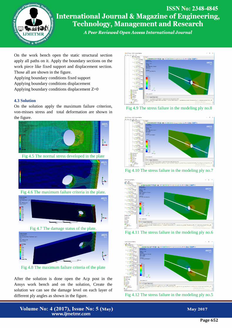
4.3 Solution
On the solution apply the maximum failure criterion,
von-misses stress and total deformation are shown in
the figure.
Fig 4.5 The normal stress developed in the plate
Fig 4.6 The maximum failure criteria in the plate.
Fig 4.7 The damage status of the plate.
Fig 4.8 The maximum failure criteria of the plate
After the solution is done open the Acp post in the
Ansys work bench and on the solution, Create the
solution we can see the damage level on each layer of
different ply angles as shown in the figure.
Fig 4.9 The stress failure in the modeling ply no.8
Fig 4.10 The stress failure in the modeling ply no.7
Fig 4.11 The stress failure in the modeling ply no.6
Fig 4.12 The stress failure in the modeling ply no.5

Page 653
Fig 4.13 The stress failure in the modeling ply no.4
Fig 4.14 The stress failure in the modeling ply no.3
Fig 4.15 The stress failure in the modeling ply no.2
Fig 4.16 The stress failure in the modeling ply no.1
Fig 4.17 Full sectional view of normal stress on the plate
Fig 4.18 Maximum failure criteria on the modeling ply
3.
Fig 4.19 Von misses stress on the plate
5.Results and Discussions
The bearing strength and maximum failure load are
investigated experimentally and numerically. The
specimens for each E/D and W/D ratio are tested for
experimental study. Bearing strength values, failure
loads are investigated for two variables, E/D ratio
(1,2,3,4,5) and W/D ratio (2,3,4,5), orientation angle of
fiber for two stacking’s [0/90/+30/-30]s , [0/90/+60/
60]s, is used in this study.
In the experimental study, we will see, graphs for failure
load and E/D, W/D ratios for two stacking’s [0/90/+30/-
30]s , [0/90/+60/-60]s and compared with the Ansys
results.
In addition, when edge distance to diameter ratio (E/D)
and width to diameter ratio (W/D) are increased, the
failure load reaches higher values.

Page 654
Table 5.1Comparison of experimental and Ansys
failure loads at W/D=2,3,4,5,6 for orientation
[0/90/+30-30]s
Table 5.2Comparison of experimental and Ansys
failure loads at W/D=2,3,4,5,6 for orientation
[0/90/+60-60]s
Fig 5.1 Effect of E/D and W/D ratios on Failure load for
[0/90/+30/-30]s
Fig 5.2 Effect of E/D and W/D ratios on Failure load for
[0/90/+60/-60]s
Fig 5.3 Effect of E/D and W/D ratios on Bearing
strength for [0/90/+30/-30]s
Fig 5.3 Effect of E/D and W/D ratios on Bearing
strength for [0/90/+60/-60]s

Page 655
6. Conclusion
When W/D=2 (the smallest value of this ratio tested), the
most dangerous mode developed. The load capacity of
the joint increased as the W/D ratio increased. When
W/D=4, full bearing failure mode was observed. Low
E/D values gave rise to shear out failure or net tension
modes. Shear out or net tension failure mode was
observed when the E/D ratio was 1. When E/D=1, the
plate was the weakest because the hole was too close.
When E/D ratio was < 2, the shear out failure mode
occurred. If E/D>2, net tension failure mode with crack
initiation at the horizontal edges of the hole developed.
In this failure mode, hole cross-section area was
minimum. If E/D ratio had low values, the net tension or
shear our failure modes developed. Increasing E/D, the
failure mode changed from shear out to bearing and the
failure load increased. While E/D was constant,
maximum failure loads increased when W/D ratio
increased. The minimum failure load was observed when
W/D=2 and E/D=1 for every stacking sequence. On the
other hand, the maximum failure load was observed
when W/D=6 and E/D=5 for every stacking sequence.
When W/D=2, the plate was the weakest. If W/D ratio
increased, the failure mode changed from net tension to
shear out while E/D=1. As the width of the specimen
increased, the failure mode also altered to bearing mode.
Therefore, the use of composite joints with small W/D
ratio was not advised.
When W/D ratio was ≥4, bearing failure mode was seen
for [0/90/+30/-30]s and [0/90/+60/-60]s stacking
sequences. Among these the preferable failure mode was
the bearing one because soon after the achievement of
maximum load, it allows the specimen to further endure
a certain load.
The bearing failure resulted in a safe behaviour with the
joint being able to support further load. Bearing failure
mode was considered to be the desirable mode since it
generally gave a higher strength and the failure was less
brittle. Bearing failure mode was local failure and
progressive.
7. REFERENCE
1. Fu-Kuo Chang, Kuo-Yen Chang, “A Progressive
Damage Model for Laminated Composite
Containing Stress Concentrations”. Journal Of
Composite Materials, 21(1987) 834-855.
2. H. J. Lin & C. C. Tsai, “Failure Analysis Of
Bolted Connections Of Composites With Drilled
And Moulded-In Hole”, Composite Structures,
30 (1995) 159-168.
3. Nahla K. Hassan, Mohamed A. Mohamdien and
Sami H. Rizkalla, “Finite Element analysis of
Bolted Connections for PFRP Composites”,
Composite part B, 27B (1996) 339-349.
4. Y. Xiong and O.K. Bedair, “ Analytical and
Finite Element Modeling of Riveted Lap Joints
in Aircraft Structure”, 39 th AIAA/ ASME/
ASCE/ AHS/ ASC Structures, Structural
Dynamics And Material Conference, April
1998/ Long Beach, CA
5. P.P. Camanho and F.L. Matthews, “A
Progressive Damage Model for Mechanically
Fastened Joints in Composite Laminates”,
Journal Of Composite Materials, 33(24) (1999)
2248-2279.
6. AlaattIcn Aktas,Ramazan Karakuzu, “Failure
Analysis Of Two- Dimensional Carbon-Epoxy
Composite Plate Pinned Joint ”,Mechanics Of
Composite Materials And Structures, 6 (1999 )
7. Th. Kermanidis, G. Lebeas, K.I.Tserpes and Sp.
Pentelakis, “Finite Element Modeling Of
Damage Accumulation In Bolted Composite
Joints Under Incremental Tensile Loading”,
ECCOMAS 2000 Barcelona, September, ( 2000)
,1-14.
8. Marie-Laure Dano, Guy Gendron and Andre
Picard,” Stress And Failure Analysis Of
Mechanically Fastened Joints In Composite
Laminates”, Composite Structures, 50 (2000)
9. Q.M. Li, R.A.W. Mines, R.S. Birch, “Static and
Dynamic Behavior of Composite Riveted Joints
In Tension”, International Journal Of
Mechanical Sciences, 43 (2001) 1591-1610.
Page 656
10. Okenwa I. Okoli and Ainullotfi Abdul-Latif,
“Failure in Composite Laminates: Overview of
an Attempt at prediction”,ELSEVIER,
Composites: Part-A: Applied Sciences and
Manufacturing , 33 (2002) 315-321.
11. K.I. Tserpes, G. Labeas, P. Papanikos and Th.
Kermanidis, “Strength Prediction Of Bolted
Joints In Graphite/Epoxy Composite
Laminates”, Composites: Part B, 33 (2002) 521–
529.
12. Bulent Murat Icten and Ramazan Karakuzu,”
Progressive Failure Analysis of Pin- Loaded
Carbon–Epoxy Woven Composite Plates”,
Composites Science and Technology, 62 (2002)
1259–1271.
13. Buket Okutan and Ramazan Karakuzu, “The
Strength Of Pinned Joints In Laminated
Composites”, Composites Science and
Technology, 63 (2003) 893–905.
14. B. Yang , E. Pan , F.G. Yuan. “Three-
Dimensional Stress Analyses In Composite
Laminates With A Pinned Hole”, International
Journal Of Solids And Structures, 40 (2003)
2017–2035.
15. J. Wang,P.J. Callus, M.K. Bannister,”
Experimental And Numerical Investigation Of
The Tension And Compression Strength Of Un-
Notched And Notched Quasi- Isotropic
Laminates”, Composite Structures, 64 (2004)
297–306.