FAIL OPERATIONAL E/E SYSTEM CONCEPT FOR FUTURE APPLICATION...
22
FAIL OPERATIONAL E/E SYSTEM CONCEPT FOR FUTURE APPLICATION IN ADAS AND AUTONOMOUS DRIVING Fail Safe – Fail Operational – Fault Tolerance – ISO 26262 Hermann Kränzle, TÜV NORD Systems
Transcript of FAIL OPERATIONAL E/E SYSTEM CONCEPT FOR FUTURE APPLICATION...
FAIL OPERATIONAL E/E SYSTEM CONCEPT FOR FUTURE
APPLICATION IN ADAS AND AUTONOMOUS DRIVING
Fail Safe – Fail Operational – Fault Tolerance – ISO 26262
Hermann Kränzle, TÜV NORD Systems

2
OUR FUNCTIONAL SAFETY CERTIFIED
PROGRAM FOR PRODUCT | PROCESS | MANAGEMENT | PERSONNEL
FOR VEHICLES | INDUSTRY | INDUSTRIAL INTERNET | IT
TÜV NORD Systems
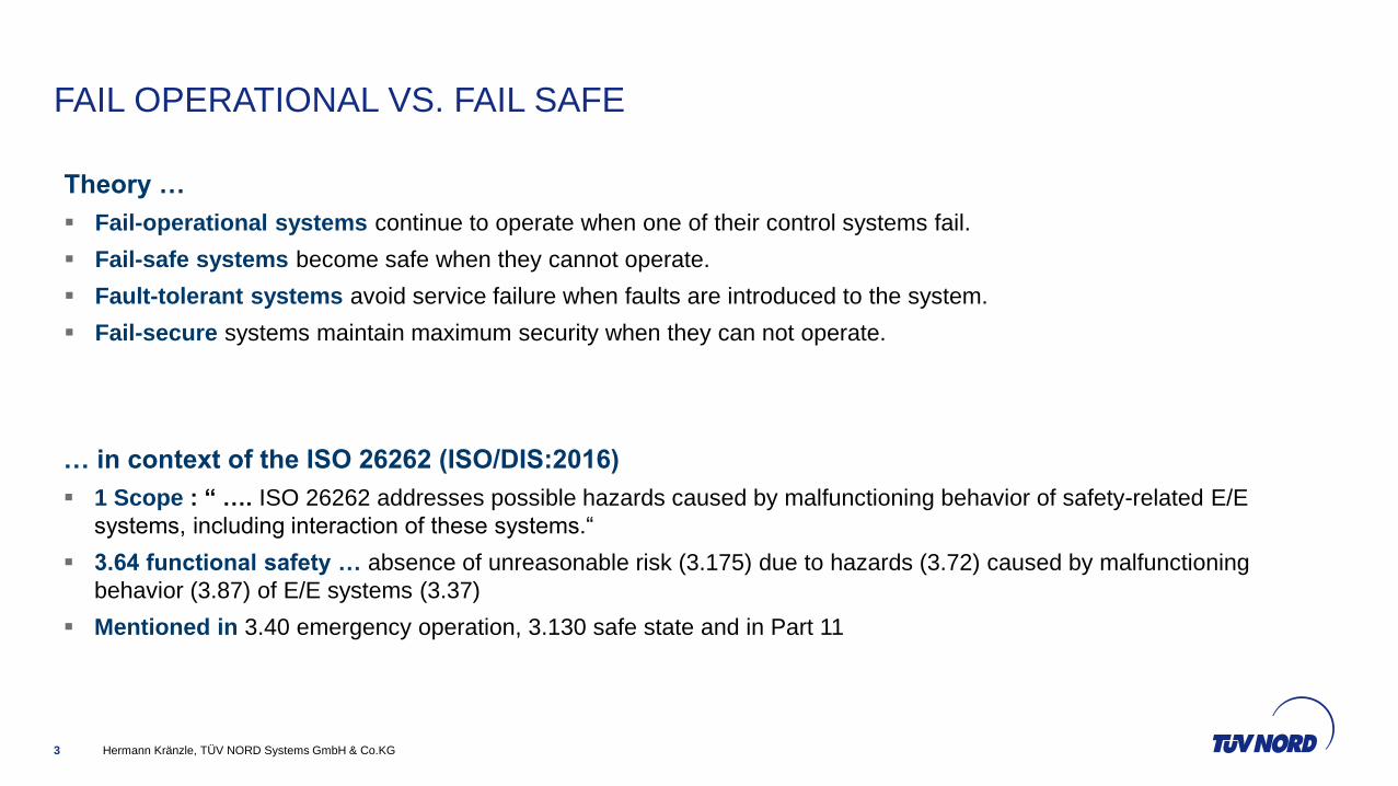
FAIL OPERATIONAL VS. FAIL SAFE
Hermann Kränzle, TÜV NORD Systems GmbH & Co.KG3
Theory …
Fail-operational systems continue to operate when one of their control systems fail.
Fail-safe systems become safe when they cannot operate.
Fault-tolerant systems avoid service failure when faults are introduced to the system.
Fail-secure systems maintain maximum security when they can not operate.
… in context of the ISO 26262 (ISO/DIS:2016)
1 Scope : “ …. ISO 26262 addresses possible hazards caused by malfunctioning behavior of safety-related E/E
systems, including interaction of these systems.“
3.64 functional safety … absence of unreasonable risk (3.175) due to hazards (3.72) caused by malfunctioning
behavior (3.87) of E/E systems (3.37)
Mentioned in 3.40 emergency operation, 3.130 safe state and in Part 11

FAIL OPERATIONAL VS. FAIL SAFE
Hermann Kränzle, TÜV NORD Systems GmbH & Co.KG4
Degre
e o
f auto
mation
Driver
only
ADAS
ADS
0
1
2
3
4
5

MOST SYSTEMS ARE FAIL SAFE
Hermann Kränzle, TÜV NORD Systems GmbH & Co.KG5
… Deactivation or degrade the function leads to a Safe State
Including the warning concept
Examples Deactivation: Adaptive Cruse control, power train, battery charging
Examples Degradation: EP-Steering, Braking ( so far …)
Fault occurs Possible hazard.
time t
Fault tolerance time
Diagnostic Test
Interval
Fault Reaction
TimeSafe stateNormal
Op.
Fault detection

EFFECT OF FAIL SOS-GOALS
Hermann Kränzle, TÜV NORD Systems GmbH & Co.KG6
Influence of system attributed like availability, reliability, safety
and security
interference and dependence of safety, fail operational and
security requirements (or goals)
Non transparency ( state, interconnection and behavior of the
system )
Sensitivity – interference of results in case of unexpected input
change
Instability – smallest disturbance cause unknown, unwanted
behavior of the system
Internal dynamics – continuous change of the system‘s state by
the system itself without any external influence

HOW ? … WHAT ARE THE CHALLENGES ?
Hermann Kränzle, TÜV NORD Systems GmbH & Co.KG7
To understand possible system design we have to make a step
back to the item definition, HARA and the functional safety
concept …
Item definition is not isolated to the E/E of the vehicles. ->
Vehicle System
Assumptions to be present (beyond ISO 26262)
“Presence of the Driver”
“Safe Place”
“Safe State Scenario”
Degradation Categories (i.e. automated lane change is not
allowed any more)
Harmonization of the behavior of all ADS (like in airborne
application) -> PAS
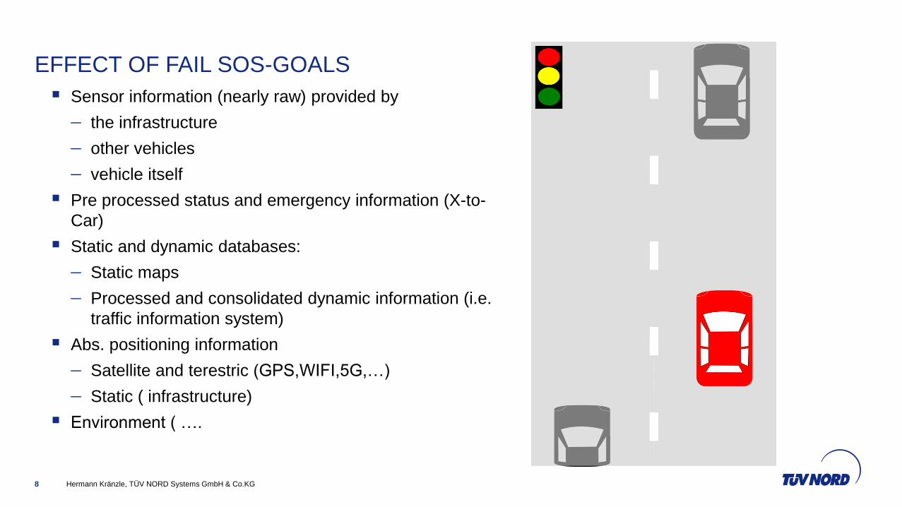
EFFECT OF FAIL SOS-GOALS
Hermann Kränzle, TÜV NORD Systems GmbH & Co.KG8
Sensor information (nearly raw) provided by
the infrastructure
other vehicles
vehicle itself
Pre processed status and emergency information (X-to-
Car)
Static and dynamic databases:
Static maps
Processed and consolidated dynamic information (i.e.
traffic information system)
Abs. positioning information
Satellite and terestric (GPS,WIFI,5G,…)
Static ( infrastructure)
Environment ( ….
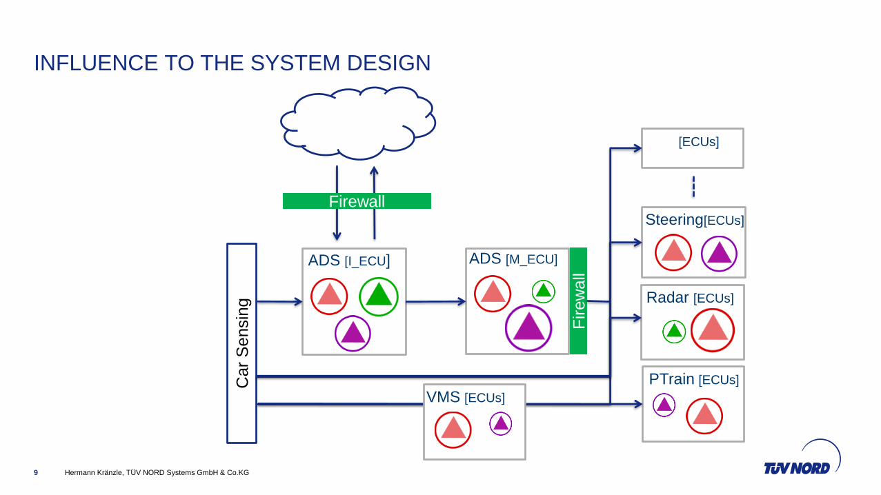
INFLUENCE TO THE SYSTEM DESIGN
Hermann Kränzle, TÜV NORD Systems GmbH & Co.KG9
ADS [M_ECU]ADS [I_ECU]C
ar
Sensin
g
FirewallSteering[ECUs]
Radar [ECUs]
Firew
all
PTrain [ECUs]
VMS [ECUs]
[ECUs]
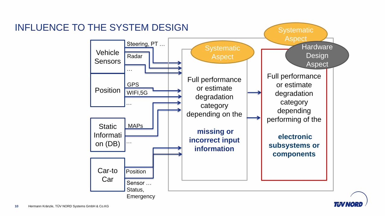
INFLUENCE TO THE SYSTEM DESIGN
Hermann Kränzle, TÜV NORD Systems GmbH & Co.KG10
Vehicle
Sensors
Car-to
Car
Static
Informati
on (DB)
Position
Radar
Steering, PT …
…
GPS
WIFI,5G
MAPs
Position
Sensor …
Status,
Emergency
…
…
Full performance
or estimate
degradation
category
depending on the
missing or
incorrect input
information
Full performance
or estimate
degradation
category
depending
performing of the
electronic
subsystems or
components
Systematic
Aspect
Systematic
AspectHardware
Design
Aspect

INFLUENCE TO THE SYSTEM DESIGN
Hermann Kränzle, TÜV NORD Systems GmbH & Co.KG11
Full performance
or estimate
degradation
category
depending on the
missing or
incorrect input
information
Full performance
or estimate
degradation
category
depending
performing of the
electronic
subsystems or
components

SYSTEM DESIGN (FAIL SAFE VS. FAIL OPERATIONAL)
Hermann Kränzle, TÜV NORD Systems GmbH & Co.KG12
A
1
AS SG
0
1
1
Motor not
operating
is safe !
unsafe state !
S
S A
S0
AS FOG
0
1
0
Motor
operating
is safe !
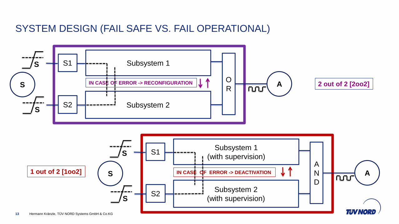
SYSTEM DESIGN (FAIL SAFE VS. FAIL OPERATIONAL)
Hermann Kränzle, TÜV NORD Systems GmbH & Co.KG13
S A
S
Subsystem 1
O
R
Subsystem 2
S1
S2
S
IN CASE OF ERROR -> RECONFIGURATION
S A
S
Subsystem 1
(with supervision)A
N
DSubsystem 2
(with supervision)
S1
S2
S
IN CASE OF ERROR -> DEACTIVATION
2 out of 2 [2oo2]
1 out of 2 [1oo2]

SYSTEM DESIGN (FAIL SAFE VS. FAIL OPERATIONAL)
Hermann Kränzle, TÜV NORD Systems GmbH & Co.KG14
WD
S1 L
PWM
S2
INT
DIC
µC 1
A
CAN
OF
F_
DIA
G
reset
EN
_L
_2
CAN
EN_L_1 t0
t1 T2
T3
CAN
CAN
T1
reset
CAN
WD
S1 ST1b
ST2b
O
R
L
2
PWM
S2
ASIC
DSP
DIC
DSP
A
EN_L_2 T2
ST1a
ST2a
O
R
L
1EN_L_1
PWM
T1
O
R
µC 2
Unsafe state the only safe state

SOME WORDING … SIMPLIFIED … FOR THE UNDERSTANDING
Hermann Kränzle, TÜV NORD Systems GmbH & Co.KG15
SPFM [Single Point Fault Metric] – “the safe portion of the
<first fault>”
(similar idea: IEC 61508 -> SFF [Safe Failure
Fraction]
LFM [Latent Fault Metric] – “the safe portion of the
<latent/multi-point fault>”
multiple-point fault (1.77)[3.96] individual
fault that, in combination with other independent
faults, leads to a multiple-point failure
PMHF[Probability Metric Hardware Fault] - failure rate of
the underlying safety goal (dangerous failure)
Similar idea: IEC 61508:PFH or in railway: THR
-
IN THE CASE OF BOTH …. ????
Hermann Kränzle, TÜV NORD Systems GmbH & Co.KG16
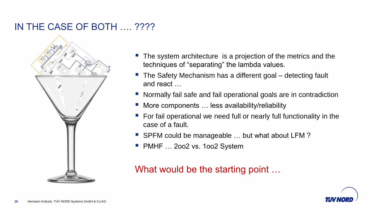
The system architecture is a projection of the metrics and the
techniques of “separating” the lambda values.
The Safety Mechanism has a different goal – detecting fault
and react …
Normally fail safe and fail operational goals are in contradiction
More components … less availability/reliability
For fail operational we need full or nearly full functionality in the
case of a fault.
SPFM could be manageable … but what about LFM ?
PMHF … 2oo2 vs. 1oo2 System
What would be the starting point …
Hermann Kränzle, TÜV NORD Systems GmbH & Co.KG17
POSSIBILITIES … IF WE TALK ABOUT ASIL C/D … WE NEED A STARTING
POINT
[X]
O
R
S1
a
S2
b
IN CASE OF ERROR -> RECONFIGURATION
SubSubsystem 1a
A
N
DSubSubsystem 1b
IN CASE OF ERROR -> DEACTIVATION
SubSubsystem 2a
A
N
DSubSubsystem 2b
IN CASE OF ERROR -> DEACTIVATION
S1
b
S2
a
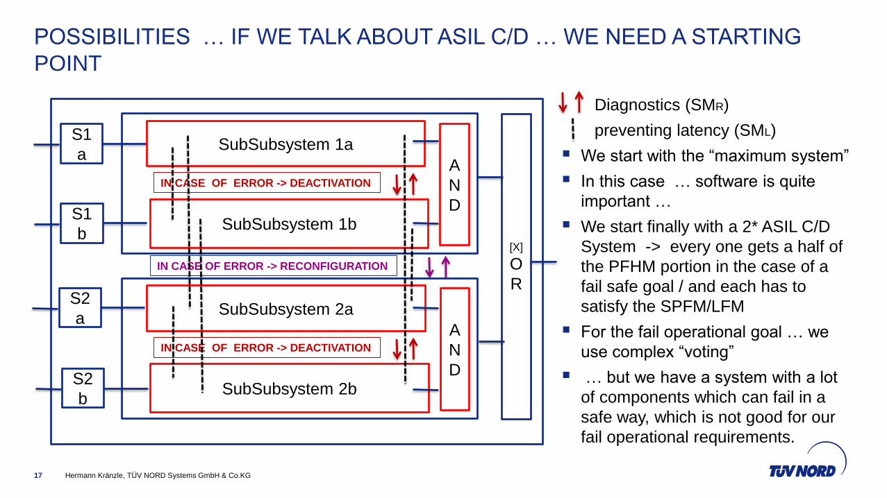
Diagnostics (SMR)
preventing latency (SML)
We start with the “maximum system”
In this case … software is quite
important …
We start finally with a 2* ASIL C/D
System -> every one gets a half of
the PFHM portion in the case of a
fail safe goal / and each has to
satisfy the SPFM/LFM
For the fail operational goal … we
use complex “voting”
… but we have a system with a lot
of components which can fail in a
safe way, which is not good for our
fail operational requirements.
Hermann Kränzle, TÜV NORD Systems GmbH & Co.KG18
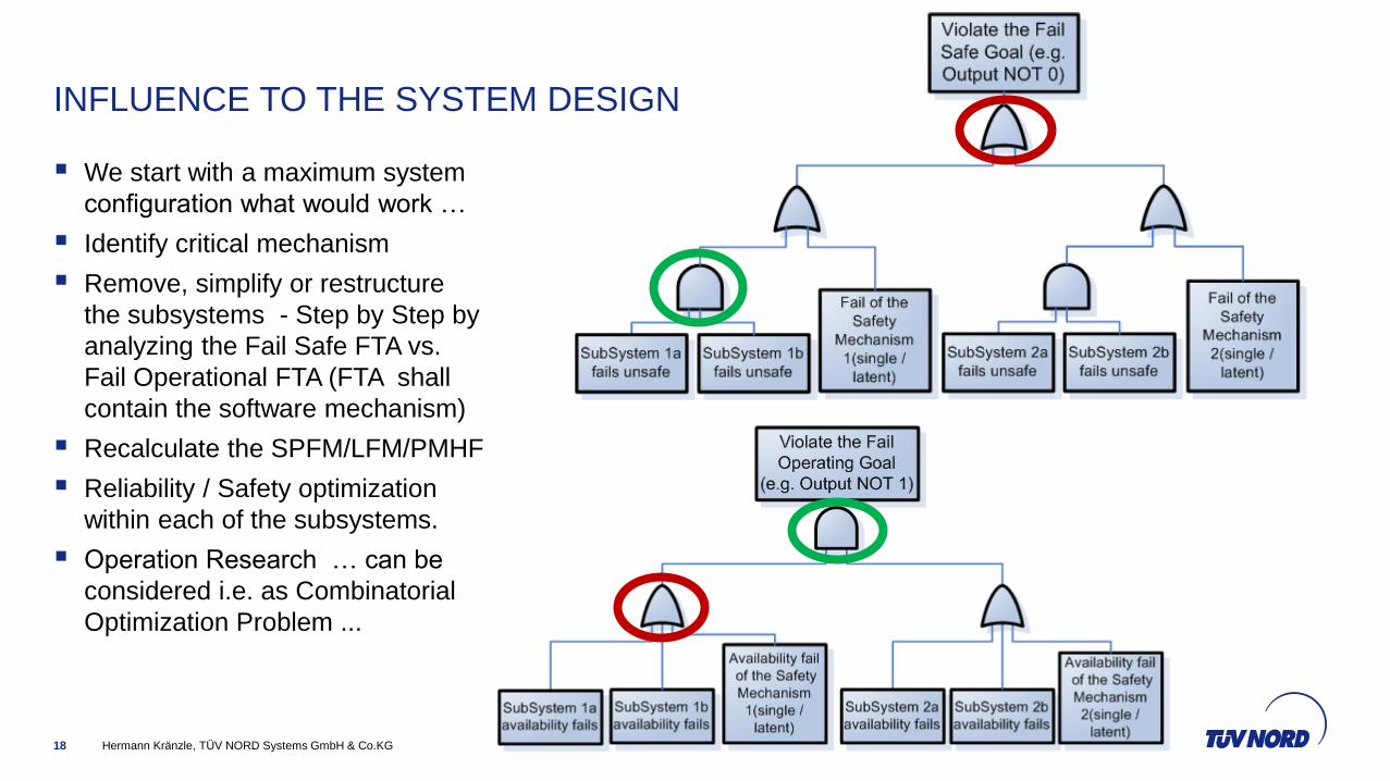
We start with a maximum system
configuration what would work …
Identify critical mechanism
Remove, simplify or restructure
the subsystems - Step by Step by
analyzing the Fail Safe FTA vs.
Fail Operational FTA (FTA shall
contain the software mechanism)
Recalculate the SPFM/LFM/PMHF
Reliability / Safety optimization
within each of the subsystems.
Operation Research … can be
considered i.e. as Combinatorial
Optimization Problem ...
INFLUENCE TO THE SYSTEM DESIGN

Hermann Kränzle, TÜV NORD Systems GmbH & Co.KG19
THE MODEL… SOME ELEMENTS
… a binary system function in disjunctive normal form where and the components
failure mode with
Be
A transformation function for failure modes which can be detected by a safety mechanism or are safe
due to architectural constraints. Further it can be shown that probability/stochastic distribution can be
directly apply in the system function in disjunctive normal form …
Hermann Kränzle, TÜV NORD Systems GmbH & Co.KG20
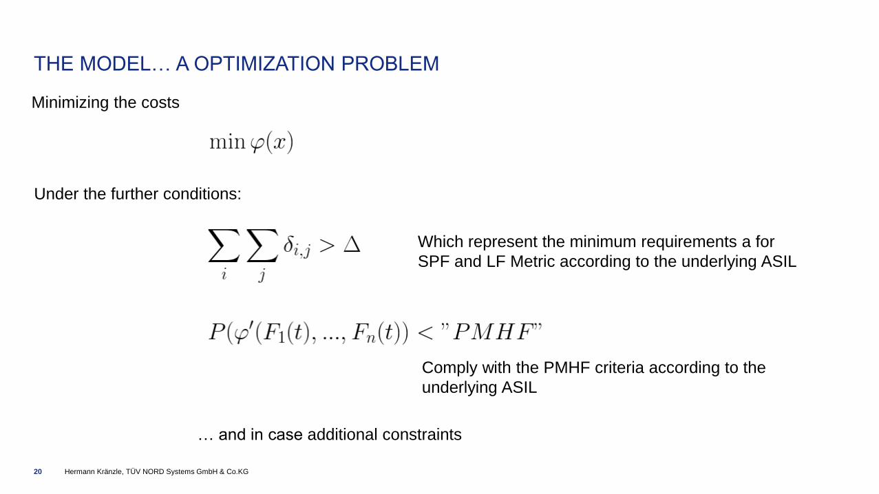
THE MODEL… A OPTIMIZATION PROBLEM
Minimizing the costs
Under the further conditions:
Which represent the minimum requirements a for
SPF and LF Metric according to the underlying ASIL
Comply with the PMHF criteria according to the
underlying ASIL
… and in case additional constraints

Hermann Kränzle, TÜV NORD Systems GmbH & Co.KG21
NOW WE TRY TO SIMPLIFY THE SYSTEM …
V
O
T
E
R
2
o
o
3
S1
S3
Subsystem 1
Subsystem 2
Subsystem 3
S2
V
O
T
E
R
S1
S2
b
Main System
Subsystem 2a
Subsystem 2b (degraded fct.)
S2
a
DEPENDING ON THE
APPLICATION, WE CAN DO
FURTHER REDUCTION…
Diagnostics (SMR)
preventing latency (SML)

Hermann Kränzle, TÜV NORD Systems GmbH & Co.KG22
THANK YOU