
Fade to Green: A Biodegradable Stack of Microbial Fuel …eprints.uwe.ac.uk/25972/1/Fade to Green...
26
1 DOI: 10.1002/cssc.201500431 Full Paper Fade to Green: A Biodegradable Stack of Microbial Fuel Cells Dr. Jonathan Winfield,* [a] Dr. Lily D. Chambers, [b] Dr. Jonathan Rossiter, [b] Andrew Stinchcombe, [a] Dr. X. Alexis Walter, [a] Prof. John Greenman, [c] and Prof. Ioannis Ieropoulos* [a] [a] Bristol BioEnergy Centre, University of the West of England, Bristol (UK) [b] Bristol Robotics Laboratory, University of Bristol, Bristol (UK) [c] Microbiology Department, University of the West of England, Bristol (UK) Abstract The focus of this study is the development of biodegradable microbial fuel cells (MFCs) able to produce useful power. Reactors with an 8 mL chamber volume, were designed using all biodegradable products: polylactic acid for the frames, natural rubber as the cation-exchange membrane and egg-based, open-to-air cathodes coated with a lanolin gas diffusion layer. Forty MFCs were operated in various configurations. When fed with urine, the biodegradable stack was able to power appliances and was still operational after six months. One useful application for this truly sustainable MFC technology includes onboard power supplies for biodegradable robotic systems. After operation in remote ecological locations, these could degrade harmlessly into the surroundings to leave no trace when the mission is complete. Key words: energy conversion, fuel cells, green chemistry, materials science, renewable resources
Transcript of Fade to Green: A Biodegradable Stack of Microbial Fuel …eprints.uwe.ac.uk/25972/1/Fade to Green...

1
DOI: 10.1002/cssc.201500431
Full Paper
Fade to Green: A Biodegradable Stack of Microbial Fuel CellsDr. Jonathan Winfield,*[a] Dr. Lily D. Chambers,[b] Dr. Jonathan Rossiter,[b] Andrew Stinchcombe,[a] Dr.
X. Alexis Walter,[a] Prof. John Greenman,[c] and Prof. Ioannis Ieropoulos*[a]
[a] Bristol BioEnergy Centre, University of the West of England, Bristol (UK)
[b] Bristol Robotics Laboratory, University of Bristol, Bristol (UK)
[c] Microbiology Department, University of the West of England, Bristol (UK)
AbstractThe focus of this study is the development of biodegradable microbial fuel cells (MFCs) able to
produce useful power. Reactors with an 8 mL chamber volume, were designed using all
biodegradable products: polylactic acid for the frames, natural rubber as the cation-exchange
membrane and egg-based, open-to-air cathodes coated with a lanolin gas diffusion layer. Forty MFCs
were operated in various configurations. When fed with urine, the biodegradable stack was able to
power appliances and was still operational after six months. One useful application for this truly
sustainable MFC technology includes onboard power supplies for biodegradable robotic systems.
After operation in remote ecological locations, these could degrade harmlessly into the surroundings
to leave no trace when the mission is complete.
Key words: energy conversion, fuel cells, green chemistry, materials science, renewable resources
IntroductionThe planet’s ecosystems are now known to be changing under the pressure of human
demand.[1] To reduce the burden and to leave a sustainable legacy for future generations, the
widespread use of renewable energy needs to be achieved and the ever-increasing production of
human waste requires urgent attention. Anthropogenic excess comes in many forms; from the

2
continuous release of food and toilet wastewaters to the discard of hazardous materials such as old
electronics, plastics and batteries. One exciting area of research is the microbial fuel cell (MFC), a
technology that employs bacteria to remove organic pollutants from liquid waste-streams with the
added bonus of the production of electricity in the process. MFCs offer great potential not only in
terms of wastewater treatment[2] but also as biosensors,[3] power supplies for continuously charging
mobile phones and small electrical applications[4,5] and for the production of useful cathodic by-
products such as caustic soda.[6] Despite the improvements in power generation and efficiency over
recent years, there is still a reliance on materials and components that are expensive or not
environmentally safe. MFCs can be considered green in terms of their contribution to renewable
energy, but paradoxically the core parts and materials might also contribute towards anthropogenic
waste. For the MFC technology to be considered feasible for target applications, both economic and
environmental costs must be minimised.[7] Other related disciplines, such as “green electronics”, are
already embracing these issues. Although energy efficiency is an important aspect in terms of end
use, it is the energy involved in the manufacturing phase that can be the most damaging to the
environment.[8] Therefore, whole-lifecycle costs must be considered, from materials sourcing and
fabrication to recycling and disposal. Biodegradable electronics are under development to reduce the
effects of waste accumulation.[9] A range of natural substrates have been employed as polymers,
which include collagen, chitin, alginate, gelatine and silk.[8] The current study investigates materials
for the development of biodegradable MFCs with an emphasis on minimum environmental impact.
One new application for biodegradable MFCs is being the power source for biodegradable robots.
Such a device should integrate with the natural environment without any negative impact and adapt
to fluctuating conditions. This makes MFCs an ideal consideration even over other bio-
electrochemical technologies because the microbial community is more dependent on the
availability, rather than on the particular type of organic fuel. This differs from enzymatic fuel cells,[10]
for example, in which pre-immobilised enzymes are limited by the type of feedstock and could be
prone to denaturation/depletion/damage in unsheltered environments. In MFCs, the variation of the
operating parameters would affect the biofilm, but as in nature, the microbial community may
acclimatise to these changes. This has been demonstrated with mixed communities to the extent
that a number of species can establish electricity-generation pathways if the environment is
conducive.[11] Adaptive evolution has also been shown in single communities in which a mutant
3
variation of Geobacter sulfurreducens emerged, which was able to produce high current densities. [12]
Until recently, the adaptation and tuning of MFC conditions to meet the needs of different and
changing environments has received less attention. However, there have been recent attempts to
find alternative, “green” materials particularly in terms of the cation-exchange membrane (CEM). The
CEM acts as the separator between the two electrodes and enables the vital movement of protons
from anode to cathode. Ceramic is now utilised as both the CEM as well as the structural material in
which porosity is integral to separation and proton movement.[13--15] In terms of biodegradable
materials, natural rubber has been shown to be a viable substitute to conventional membranes, for
which laboratory gloves[16,^17] and condoms[18] have both been employed successfully. In these
previous studies the biodegradation of the material actually enhanced the performance, whilst the
longevity of MFCs was unaffected. In effect, the natural rubber played a dynamic role in the MFC
environment and matured alongside the microbiological community to result in a system that
improved over time. This study goes beyond previous work to incorporate new materials alongside
natural rubber to produce a truly organic, totally biodegradable and ecologically safe power-
producing system. The only non-biodegradable material used was metal wire to ensure efficient
current collection.
Results and DiscussionSeveral steps were taken to develop the biodegradable stack. Alongside the natural rubber
membranes, a biodegradable frame was designed to improve the robustness of each MFC and was
achieved with 3D printing techniques using polylactic acid (PLA). PLA is compostable and is also
biodegradable in seawater and other environments.[19] For the anode, carbon veil with a polyvinyl
alcohol (PVA) binder was used. The carbon fibres in carbon veil are non-toxic and benign to the
environment, and PVA is a synthetic biodegradable polymer.[19] Several cathodes were tested, which
include egg and gelatine-based composites, and incorporate naturally produced sheep’s wax
(lanolin). The cathode that showed the best performance from these comparison tests was then used
for the next stage of the study. Using a new design, stacks of biodegradable MFCs were constructed
that are able to produce sufficient energy to power applications both directly and through the
incorporation of energy-harvesting electronics.

4
PLA framesPrevious work has demonstrated that inexpensive soft MFCs can be produced using the
finger pieces removed from natural rubber laboratory gloves and coated with conductive synthetic
latex (CSL).[17] In the current study, a more rigid structure was required to better configure the
reactors into uniform stacks, and for this reason PLA frames were designed and printed. In addition
to the production of a more robust structure, the new MFCs with PLA frames generated almost
double the power output compared to the soft “finger of glove” MFCs (data not shown). By
incorporating a frame, the anode was held firmly in place and positioned so that the rubber
membrane was in direct contact with its surface. This meant that the distance between anode,
cathode and the natural rubber membrane was reduced, which contributed to the improved
performance.[20] In addition, the natural rubber had to be stretched over the frame, which could
improve performance on two fronts. Firstly, by decreasing the thickness, that is, reducing the
travelling time for proton exchange and, secondly, the alignment of polymer chains in the material
could contribute to increased proton transfer. PLA is considered as a “green plastic” [19] and
biodegradation can be rapid at optimum composting temperature and humidity. [21] In the current
study, PLA samples were buried in the Bristol botanic gardens composting area in which an average
temperature of approximately 18°C was recorded. This temperature was too low during the
experimental period for any significant degradation of the PLA to be observed. However, if we
consider the operation of a hypothetical biodegradable robot, if more rapid degradation was
required and rigidity was a prerequisite, alternative materials could be employed for the
frame/chassis, like for example, composite lignin, wood or even paper.[22]
Suitability of conductive synthetic latexCSL works well as the cathode if coated on to a natural rubber membrane [17] however, for the
purposes of the current study in which biodegradability is essential, a CSL cathode might not be
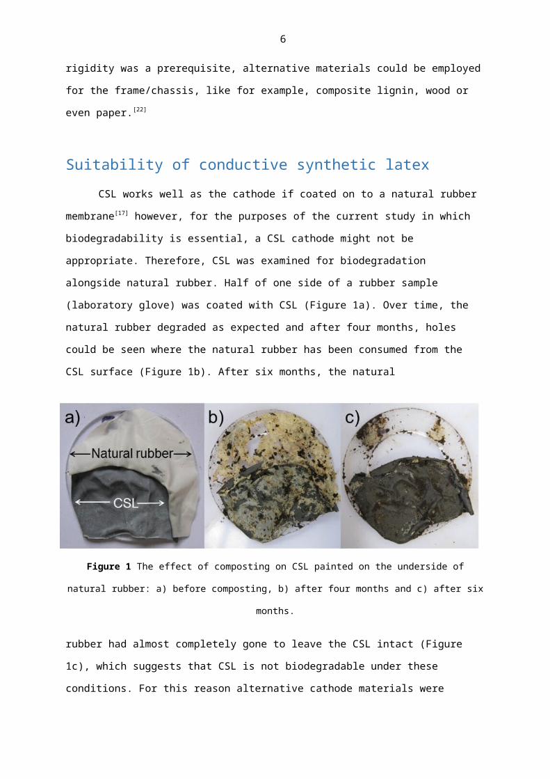
appropriate. Therefore, CSL was examined for biodegradation alongside natural rubber. Half of one
side of a rubber sample (laboratory glove) was coated with CSL (Figure 1a). Over time, the natural
rubber degraded as expected and after four months, holes could be seen where the natural rubber
has been consumed from the CSL surface (Figure 1b). After six months, the natural
5
Figure 1 The effect of composting on CSL painted on the underside of natural rubber: a) before composting, b)
after four months and c) after six months.
rubber had almost completely gone to leave the CSL intact (Figure 1c), which suggests that CSL is not
biodegradable under these conditions. For this reason alternative cathode materials were tested in
terms of their power-producing capabilities and propensity to biodegrade.
Alternative biodegradable cathodesThree alternative cathodes were developed and compared to CSL; an off-the-shelf non-toxic
carbon-based conductive paint, a gelatine-based mixture and an egg-based mixture. After the MFCs
were coated with each cathode material, the surface resistance was measured from top to bottom (6
cm) of each MFC. The conductive paint was the least resistive at 50 Ω (standard deviation (STD): 2.83)
followed by CSL: 288 Ω (STD: 17.68), then the egg-based mixture at 318 Ω (STD: 123.03) and the
gelatine-based mixture was the most resistive at 465 Ω (STD: 21.21).
Electrochemical analysis in the form of polarisation sweeps was performed after six weeks,
and CSL was five times more powerful than the next closest cathode type, which was the conductive
paint (Figure 2a). These preliminary results suggested that the chosen materials might not be as
suitable as CSL. However, in an attempt to improve their performance, a diffusion layer was applied.
Diffusion layers are employed on the air-facing side of the cathode electrode to prevent water
leakage through the electrode and to improve oxygen transfer.[23] Materials commonly used include
polytetrafluoroethylene (PTFE) and polydimethylsiloxane (PDMS),[24] which are hydrophobic and
relatively inexpensive but not biodegradable. Lanolin, also known as wool wax, is a naturally
6
Figure 2 Power curves produced from different cathode types: a) after six weeks operation (before lanolin
application) and b) after eight weeks operation (following lanolin application). Data presented as mean and
range (n=2).
occurring substance secreted by sheep to waterproof the wool and to prevent water loss. After six
weeks of operation, lanolin was applied to the surfaces of all the MFCs. Both the egg-based and the
gelatine-based cathodes demonstrated immediate and rapid improvement to the extent that one of
the gelatine MFCs showed a six-fold improvement in performance. Neither the CSL MFCs nor the
paint MFCs responded positively following the application of lanolin. The CSL mixture incorporates

7
polyurethane as binder, which has been used previously as the sole diffusion layer in MFCs. [14] This
could explain why the application of an additional diffusion layer did not improve the performance.
In addition, there was little improvement in the conductive paint MFCs probably because----as it is
water soluble----the paint became diluted both through operation and with the addition of lanolin.
The improvement in both egg and gelatine is reflected in the power curves produced after eight
weeks (two weeks after the application of lanolin), and the egg MFCs actually outperformed the CSL
MFCs (Figure 2b). To verify that the new cathode materials were biodegradable, samples were tested
in the ground. Natural rubber coated with gelatine, conductive paint and egg-based cathodes all
degraded at the same rate.
Figure 3 Biodegradation of egg-based cathode on natural rubber. Without lanolin layer: a) before composting,
b) after two months and c) after four months. With lanolin layer: d) before composting, e) after two months
and f) after four months.
These are represented by the images of the egg-based material in Figure 3a-c, in which all
samples had completely degraded by the end of the fourth month. A coating of lanolin did not affect
the rate of biodegradation (Figure 3d-f). The egg-based cathodes with a lanolin diffusion layer were
the best of the biodegradable cathodes and even outperformed the CSL cathodes (Figure 2b). As a

8
result, these were employed in the development of the biodegradable stack. The utilisation of egg
yolk was inspired by its use as egg tempera in the preparation of paint. The earliest historic evidence
of its use was in paints prepared by the ancient Egyptians and Greeks. Tempera paints were
particularly fashionable during the Renaissance and are still used by artists today. This is because egg
yolk is a highly efficient emulsive binder that adheres well, dries quickly and is durable [25] with good
protection against humidity and temperature changes. These characteristics will have contributed to
the effectiveness of the egg-based cathodes and are also desirable traits in terms of the robustness
of the biodegradable MFCs. For this reason, 40 MFCs were constructed using egg-based cathodes
with the aim to produce a functional biodegradable stack.
Biodegradable stack of MFCs
Figure 4 Stack configurations in which A=anode and C=cathode: a) parallel set-of-five MFCs, b) four parallel
sets-of-five connected together in series, c) eight parallel sets-of-five connected together in series.

9
Forty MFCs were constructed, with an eight stack formation, where each stack consisted of
five MFCs connected electrically in parallel (Figure 4a); these will be referred to as parallel sets. After
the first set of experiments, these were configured into two stacks that each comprised four of the
parallel sets connected to each other in series (Figure 4b). Finally, all 40 MFCs were configured into
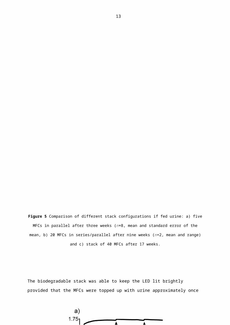
one series/parallel configuration (Figure 4c). Power and polarisation curves that show the average
from the eight parallel sets are shown in Figure 5a. There was considerable variation between the
best performance (246 μW or 6.16 W m3) and the worst performance (54 μW or 1.35 W m3) of the
parallel sets. After eight weeks of operation, the two larger stacks were formed (Figure 4b), and the
power and polarisation curves are highlighted in Figure 5b. Finally, all eight parallel sets were
connected together in series to result in one 40-MFC series-parallel configuration (Figure 4c), and the
power and polarisation curves are displayed in Figure 5c. Over time and with each new configuration,
the actual circuit current increases but the current density (based on the total volume of each stack)
decreases. For example, at the point of maximum power, the average current calculated from the
parallel sets-of-five MFCs is 750 μA (18 A m3) compared to 1 mA (6.25 A m3) for the stack of 20 and
1.05 mA (3.28 A m3) for the stack of 40. The stacks were operated in fixed configurations, but it has
been reported recently that by dynamically switching between configurations, the performance can
be optimised,[26] which ultimately prevents current density losses. However, the power density does
improve such that the stack of 40 (320 mL) has a superior power density (4.08 W m3) than the
average of the stacks of five (40 mL) at 2.87 W m3.
This confirms that a combined series/parallel configuration can be an efficient way of
stepping up power in MFC stacks.[27] The open-circuit voltage (OCV) of the stack of 40 (3.11 V),
although it does not reach the theoretical OCV calculated from the stacks of five (436 mV x 8 = 3.49
V), was consistent and sufficiently high to test the electrical capabilities when implemented in real
applications. To demonstrate that the biodegrading stack (aged 17 weeks) could generate useful
electricity, a light-emitting diode (LED) was connected directly to the stack without any energy-
harvesting electronics. The biodegradable stack was able to maintain constant and bright illumination
with feeding only required every three days. To demonstrate recovery, the stack was starved for two
weeks before it was fed with fresh urine, and the recovery and subsequent stability is highlighted in
Figure 6a. It took just 10.5 h for the stack to climb to 1.54 V, which was sufficient to fully illuminate
the LED and 46 h to reach the 1.7 V required for stable operation.

10
Figure 5 Comparison of different stack configurations if fed urine: a) five MFCs in parallel after three weeks
(n=8, mean and standard error of the mean, b) 20 MFCs in series/parallel after nine weeks (n=2, mean and
range) and c) stack of 40 MFCs after 17 weeks.

11
The biodegradable stack was able to keep the LED lit brightly provided that the MFCs were topped up
with urine approximately once every three days. The long-term stable performance is emphasised in
Figure 6a, which shows the stack behaviour over more than eight days.
Figure 6 Performance of biodegradable stack: a) attached directly to an LED after two weeks of starvation; b)
charge/discharge cycle of MFC stack and 0.75F capacitor bank. Arrows in both figures indicate when the MFCs
were topped up with fresh urine.
The illumination of LEDs can be worthwhile, however, a stack of biodegradable MFCs might
be required to power applications that are more energy intensive. For this reason the stack was
connected to a power-management system that comprised energy-harvesting electronics with a
custom-made hysteresis board and four capacitors connected in series (with a resulting capacitance

12
of 0.75 F and a voltage of 10.8 V). The hysteresis board discharged the capacitors at 8.5 to 5 V
through a load, and the charge/discharge cycle over a 100 h period is shown in Figure 6b. Each
discharge released enough energy (up to 20 J per discharge) to activate a range of useful
applications. Provided that the stack was fed with urine regularly, it maintained the cycle and on
average discharged every 9 h and continued to operate beyond 24 weeks.
As proposed earlier, a biodegradable stack of MFCs could be used to power a biodegradable
robot, perhaps to fuel locomotion or a pumping mechanism. Recently, biodegradable gelatine
artificial muscles have been developed[28] that actuate within the same voltage and current range as
produced by the biodegradable stack in this study. These are promising developments in the field of
biodegradable robotics as it now appears that the right components are in place for actuation and
power generation. A clear consideration with biodegradable MFCs is the length of time of operation.
The data shown in Figure 6b were generated when the stack was close to five months old. Some
visual signs of degradation could be seen, but the MFCs continued to generate useful power. The
conditions in which an MFC operates (i.e., anaerobic internal environment, neutral pH, the use of
specialist electro-active organisms) are very different to other natural environments, and so the
lifetime of the materials might be prolonged during MFC operation. This is highlighted by the fact
that if buried in the ground, the natural rubber with the egg-based cathode material and lanolin had
degraded completely by the fourth month (Figure 3f) but as functioning MFC components in the
stack, they were still intact and operational after six months. It was observed that if fuel was no
longer fed and the MFCs ceased operation, biodegradation appeared to accelerate. This was
apparent after the two-week period of starvation when, after feeding, there were leaks in some of
the MFCs that were not present before the period of inactivity. Interestingly, after several days of
operation, some of these leaks disappeared as the system seemed to “self-seal”, perhaps because of
precipitation and biofilm growth.
Over the course of the study, there was a build-up of precipitate in the bottom of the anode
chamber. The biodegradable MFC design did not allow for analysis of the precipitant, but struvite
accumulation has been reported in other studies using urine.[29,30] For long-term operation this could
be considered a hindrance by causing blockages to operation, however, for biodegradable systems,
struvite accumulation might be a benefit because once the MFCs have reached the end of their
13
mission, this valuable nutrient could either be released to the land or increase the biodegradability of
the system in oligotrophic environments.
The coulombic efficiency (1.1 %) and power density (4 W m3) were low compared to those of
previous studies in which MFCs were constructed from expensive, non-biodegradable and
unsustainable materials. For example, in studies using Pt-based cathodes, power densities of over 2
kW m3 have been reported with Coulombic efficiencies of above 80 %.[31] Clearly, a lot of further work
is required to reach these levels using biodegradable components, but this study demonstrates that
potentially any material can be employed to produce meaningful power. These are key findings for
the progress of new sustainable technologies because they demonstrate that useful energy can be
produced even using simple, inexpensive, non-hazardous materials. Furthermore, this was achieved
using oxygen-breathing cathodes, free of any catalyst, and with urine as the fuel. Finally, in the
current study, a complex mixed electro-active community was used to inoculate the MFCs. For
practical implementation the user may require the system to degrade at a specified rate or begin to
degrade at a designated time. For this reason an interesting avenue of work would be the
incorporation of specific species to accelerate biodegradation.
ConclusionsThis is the first time that a fully biodegradable stack of microbial fuel cells (MFCs) able to
power real applications has been reported. Carbon was used as the conductive element in both
electrodes, which, although not biodegradable, can be deemed harmless in nature. Metal in the form
of nickel chrome wire was included to ensure efficient electrical connection and current collection.
Future work should look at alternatives to metallic wire including graphite layers, incorporation of
dissolvable electronics and/or through fluidic tubes that utilise the conductivity of the fuel to form
the electrical connections. The components required for building each MFC in the current study cost
just £0.40 (0.70€), which further demonstrates the feasibility to exploit the technology in a wide
market. This innovative study highlights the potential that MFCs can offer to future societies both in
terms of cost and sustainability.

14
Experimental SectionMicrobial fuel cell design
Figure 7 Construction of biodegradable MFCs: a) CAD drawing of the frame, A=feed hole and B=hole for anode
wire, b) 3D printed PLA frame, c) anode wrapped around frame threaded with current-collecting wire, d)
natural rubber “finger cot” that covers the anode and frame wrapped with current-collecting wire, e) stack of
completed MFCs after the application of cathodes.
Each individual MFC consisted of a biodegradable PLA frame designed using CAD software
(SolidWorks; Figure 7a) and printed with a 3D Touch 3D printer (Figure 7b). A 5 mm hole was
incorporated into the top for the injection of feedstock, and the bottom of the frame was sealed. A

15
second hole, 1 mm in diameter, was included in the top for the anode current-collecting wire. An
internal feed channel passed through the length of the frame until it reached the sealed bottom.
Sixteen holes were introduced into the design so that feedstock could permeate into the anode. The
anode was a 50 × 3 cm piece carbon veil with PVA binder (20 g m2, PRF Composite Materials, Poole,
UK). This was wrapped around the frame and held in place with two strips of biodegradable grafting
tape (Agroforestry, Totnes, UK; Figure 7c). For current collection, nickel chrome wire (0.45 mm,
Scientific Wire Company, UK) was pierced through the anode and threaded out of the pre-prepared
hole. Latex rubber finger cots (generic suppliers, Ebay, UK) were slid up the anode-wrapped-frame
before a small piece of nickel chrome wire was tightened around the centre (Figure 7d). Two coats of
cathode solution (preparation detailed in the next section) were painted over the surface of the
natural rubber. A stack of complete MFCs is shown in Figure 7e. Each MFC had an internal anode
chamber volume of 8 mL.
Cathode preparationOnce the MFCs were at the correct stage of development (Figure 1d), one of four different
types of cathodes were painted over the natural rubber membranes of each MFC. The four cathode
types initially investigated were CSL, egg, gelatine and non-toxic carbon-based conductive paint. The
CSL was prepared as described previously[17] with a 3:1 ratio of graphite powder to polyurethane
(Plasti dip, Petersfield, UK) using naphtha as solvent. The egg-based cathodes were prepared as
follows: after separation and the disposal of the egg white, egg yolk (5 mL) was mixed with deionised
water (7 mL) and graphite powder (5 g; Graphite Trading Co., Halesowen, UK). The gelatine-based
cathode was prepared as follows: leaf bovine gelatine (1 g, Home baking leaf gelatine, Asda, UK) was
dissolved in deionised water (6 mL) at 50°C and graphite powder (3 g) was stirred into the mixture.
Finally, an off-the-shelf water-based conductive paint (Bare Conductive, Proto-Pic, UK) was used.
Duplicate MFCs were operated for each of the four cathode types. After a period of operation and to
examine the effect on performance, the cathodes of all the MFCs were coated with lanolin sheep
wax (anhydrous, Pure n Simple, UK).

16
Individual MFC inoculation and operationMFCs were inoculated using mature microbial communities in the anolyte (tryptone yeast
extract) removed from separate established, cubic MFCs. They were initially left in open circuit for 24
h before a 1 kΩ load was connected. MFCs were fed on a regular basis by injecting feedstock into the
anode chamber. The anolyte did not need to be physically removed from the chambers at any stage
because there was significant daily loss due to depletion and/or evaporation. The 8 mL MFCs needed
to be topped up with approximately 2 mL of feedstock daily, which equates to a volumetric loading
of 10 mL MFC-1 day-1. Feedstock (anolyte) was tryptone (1 % w/v) yeast extract (0.5 % w/v) for the
cathode-comparison experiment, and fresh human urine was used for all the other experiments.
Fresh urine (no more than 1 h old) was always used and had on average a pH of 7.14, conductivity of
14.2 mS cm-1, urea concentration of 1.82 mg L-1, ammonium concentration of 1 mg L-1, nitrate
concentration of 20.5 mg L-1, orthophosphate concentration of 1 g L-1 and a chemical oxygen demand
(COD) of approximately 10 g L-1.The cathodes did not require hydration. All experiments were
performed at ambient temperature conditions (22 ± 1 °C).
Stack inoculation, configuration and operationInformed by the results of the cathode-comparison experiment, 40 identical MFCs were built
all with egg-based cathodes and a coating of lanolin. Groups of five individual MFCs were connected
together electrically in parallel (with nickel chrome wire) to result in eight identical “parallel sets-of-
five” modules (Figure 4a). These were inoculated using the anolyte (urine) removed from established
MFCs and operated under an external resistance of 200 Ω. All MFCs in the stack experiments were
fed with fresh human urine. After five weeks, the eight stacks were configured into two larger stacks,
each of which comprised four parallel sets-of-five, connected together in series (Figure 4b) to result
in two stacks of 20 MFCs, each operated under an external resistance (REXT) of 400 Ω. After 10 weeks,
all eight parallel sets-of-five were connected together in series to create one stack of 40 MFCs and
attached to a red LED (HLMP-D150, Avago Technologies). Finally the stack of 40 was connected to a
power-management system that consisted of an energy-harvesting board (EH4295, Advanced Linear
Devices Inc., CA, USA), a custom-made hysteresis board and capacitors as described previously. [17] To
accumulate higher voltages, four capacitors (each with a capacitance of 3 F at 2.7 V) were connected

17
in series to produce a capacitance of 0.75 F at 10.8 V. The hysteresis board discharged the capacitors
through a load (430 Ω resistor) from 8.5 to 5 V at which point the charging cycle started again. The
time taken for the capacitors to discharge was approximately 170 s before the charge cycle started
again.
Data collection and analysisThe MFC output [mV] was recorded against time by using an Agilent LXI (34972A) data
acquisition/switch unit with a 2 min sample rate. Recorded data were processed and analysed by
using the GraphPad Prism version 6 software package (GraphPad, San Diego, CA, USA). Current I [A]
was calculated using Ohm’s law, I=V/R, in which V is the measured voltage [V] and R is the known
value of the external resistive load in [Ω]. Power P [W] was calculated by multiplying voltage with
current: P=I×V. For power/current density calculations, the total anode chamber volumes were used
(i.e., one MFC = 8 mL, stack of five = 40 mL, stack of 40 = 320mL). Coulombic efficiency (CE) was
calculated according to the method of Logan et al.[32] using average current data over a 72 h period
based on the change in COD. The pH was measured by using a pH meter (HANNA pH209), and the
conductivity was recorded by using a multi-range conductivity meter (HANNA Instruments HI 9033).
For COD, the urine was filter-sterilised using 0.2 μm filters and analysed using COD HR test vials
(CamLab, Cambridge, UK) and analysed by using a Lovibond MD200 Photometer. All other water
analysis was performed using test kit reagents (Lovibond, Amesbury, UK) and a MC500 Camlab
Colorimeter.
Polarisation experimentsPolarisation experiments were performed by using an automated computer-controlled
variable resistor as described previously.[33] A total of 60 resistance values were applied from 1 MΩ
down to 3 Ω using a sample rate of 5 min. The computer-controlled variable resistor can only log
voltages up to 2.5 V, therefore, for the polarisation of the 40-MFC stack, a manual variable resistor
(Centrad Boite A Decades De Resistances DR07) was employed.

18
BiodegradationTo examine biodegradation in nature, natural rubber samples as substratum matrix were
coated with the cathode material and attached to ring-shaped acrylic tokens with an outer diameter
of 5 cm and an inner diameter of 3 cm. The tokens were placed on a frame and buried in an outdoor
compost pile (Botanic Gardens, Bristol). Approximately every two weeks, the frame was dug up for
samples to be photographed and weighed before returning to the compost heap.
AcknowledgementsThe authors would like to thank The Leverhulme Trust for their financial support through Project
Grant RPG-362. Thanks also go to Nick Wray, Andy Winfield and the Bristol Botanic Gardens who
provided access to their grounds and facilities for the biodegradation experiments. Ioannis Ieropoulos
is an EPSRC Career Acceleration Fellow supported by grant numbers EP/I004653/1 and EP/L002132.
References[1] P.M. Cox, R.A. Betts, C.D. Jones, S.A. Spall, I.J. Totterdell, Nature 2000, 408, 184-187.
[2] Z.W. Du, H.R. Li, T.Y. Gu, Biotechnol. Adv. 2007, 25, 464-482.
[3] B.H. Kim, I.S. Chang, G.C. Gil, H.S. Park, H.J. Kim, Biotechnol. Lett. 2003, 25, 541-545.
[4] I. Ieropoulos, P. Ledezma, A. Stinchcombe, G. Papaharalabos, C. Melhuish, J. Greenman,
Phys. Chem. Chem. Phys. 2013, 15, 15312-15316.
[5] I. Ieropoulos, J. Greenman, C. Melhuish, I. Horsfield, Artificial Life XII, MIT Press, 2010, 733-
740.
[6] I. Gajda, J. Greenman, C. Melhuish, C. Santoro, B. Li, P. Cristiani, I. Ieropoulos, Sustain. Energy
Technol. Assess. 2014, 7, 187-194.
[7] D. Pant, A. Singh, G. Van Bogaert, S.I. Olsen, P.S. Nigam, L. Diels, K. Vanbroekhoven, RSC Adv.
2012, 2, 1248-1263.
[8] M. Irimia-Vladu, Chem. Soc. Rev. 2014, 43, 588-610.
[9] C.J. Bettinger, Z. Bao, Adv. Mater. 2010, 22, 651-644.
[10] D. Leech, P. Kavanagh, W. Schuhmann, Electrochim. Acta, 2012, 84, 223-234.

19
[11] N.J. Beecroft, F. Zhao, J.R. Varcoe, R.C.T. Slade, A.E. Thumser, C. Avignone-Rossa, Appl.
Microbiol. Biotechnol. 2012, 93, 423-437.
[12] H. Yi, K.P. Nevin, B. Kim, A.E. Franks, A. Klimes, L.M. Tender, D.R. Lovley, Biosens. Bioelectron,
2009, 24, 3498-3503.
[13] M. Behera, P.S. Jana, M.M. Ghangrekar, Bioresour. Technol. 2010, 101, 1183-1189.
[14] F.F. Ajayi, P.R. Weigele, Bioresour. Technol. 2012, 116, 86-91.
[15] J. Winfield, J. Greenman, D. Huson, I. Ieropoulos, Bioprocess Biosyst. Eng. 2013, 36, 1913-
1921.
[16] J. Winfield, L.D. Chambers, J. Rossiter, J. Greenman, I. Ieropoulos, Int. J. Hydrogen Energy,
2014, 39, 21803-21810.
[17] J. Winfield, L.D. Chambers, A. Stinchcombe, J. Rossiter, I. Ieropoulos, J. Power Sources, 2014,
249, 327-332.
[18] J. Winfield, I. Ieropoulos, J. Rossiter, J. Greenman, D. Patton, Biodegradation, 2013, 24, 733-
739.
[19] E.S. Stevens in Green Plastics – An Introduction to the New Science of Biodegradable Plastics,
Princeton University Press, USA, 2002.
[20] H. Liu, S.A. Cheng, B.E. Logan, Environ. Sci. Technol, 2005, 39, 5488-5493.
[21] K. Ho, A. Pometto, J. Environ. Polym. Degrad. 1999, 7, 101-108.
[22] J. Winfield, L.D. Chambers, J. Rossiter, J. Greenman, I. Ieropoulos, J. Mater. Chem. A, 2015,
13, 7058-7065.
[23] Y. Ahn, F. Zhang, B.E. Logan, J. Power Sources, 2014, 247, 655-659.
[24] F. Zhang, T. Saito, S. Cheng, M.A. Hickner, B.E. Logan, Environ. Sci. Technol. 2010, 44, 1490-
1495.
[25] R.J. Boyle, H. Brown, R. Newman in Milk and Eggs: The American Revival of Tempera Painting
1930-1950, University of Washington Press, Washington USA, 2002.
[26] G. Papaharalabos, J. Greenman, A. Stinchcombe, I. Horsfield, C. Melhuish, I. Ieropoulos, J.
Power Sources, 2014, 272, 34-38.
[27] I. Ieropoulos, J. Greenman, C. Melhuish, Int. J. Energ. Res. 2008, 32, 1228-1240.
[28] L.D. Chambers, J. Winfield, I. Ieropoulos, J. Rossiter, Proc. SPIE 9056, 2014,
doi:10.1117/12.2045104.

20
[29] C. Santoro, I. Ieropoulos, J. Greenman, P. Cristiani, T. Vadas, A. Mackay, B. Li, J. Power
Sources, 2013, 238 190-196.
[30] P. Kuntke, K. M. Smiech, H. Bruning, G. Zeeman, M. Saakes, T.H.J.A. Sleutels, H.V.M.
Hamelers, C.J.N. Buisrnan, Water Res, 2012, 46, 2627-2636.
[31] Y. Fan, S. Han, H. Liu, Energy Environ. Sci., 2012, 5, 8273-8280.
[32] B.E. Logan, B. Hamelers, R. Rozendal, U. Schröder, J. Keller, S. Freguia, P. Aelterman, W.
Verstraete, K. Rabaey, Environ. Sci. Technol. 2006, 40, 5181-5192.
[33] N. Degrenne, F. Buret, B. Allard, P. Bevilacqua, J. Power. Sources, 2012, 205, 188-193.