Facts worth knowing about Oil pumps - Danfoss...
74
Facts worth knowing about Oil pumps
Transcript of Facts worth knowing about Oil pumps - Danfoss...
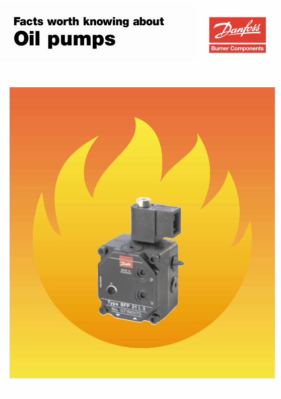
Facts worth knowing about
Oil pumps

1
Facts worth knowing about oil pumpsIndex
Page
Introduction 5
How does an oil pump vork 6
High pressure oil pump principle 9
What is a trochoidal gearwheel set? 10
Pressure regulating valve 11
Why a cut off is required? 12
Why are there different types of oil pumps? 13
Regulating a cut-off valve 14
Diagram regulation 15
What is a t two-stage oil pump? 16
Which units of measurement are used in connecton withoil pumps? 17
Pressure 18
Vacuum 19
Viscosity 20
Speed 21
Energy consumption 22
Capacity 23
Temperature 25
The oil pump in the installation 27
Relationship between tank andburner – suction height/suction length 28
How to select the correct pipe diameter and pipe length 30
What devices ought to be used in the suction line 31
How various resistances in the suction line affect the pump 32
Why use one-pipe or two-pipe system 33
How to change over a Danfoss oil pump from one-pipeto two-pipe operation 34
When and how must the pump be bled 35
Questions that can arise when working with oil pumps 36
What do the pump instructions contain? 37
What happens if the wrong tools are used? 38
How can the condition of the pump be checked? 39
What ought to be checked before a complaintis made about the oil pump? 40
What significance have the oil characteristics? 41
2
Page
Will the pump be ruined if it is run on paraffin? 42
Why is it necessary to watch for water in the oil? 43
How should the oil filters be looked after? 45
What happens if the suction andreturn linesare swapped over? 46
What happens if the two-pipe screw is fitted incorrectly? 47
Should the pump suction side be subjected to pressure? 49
What are the risks in do-it-yourself pump dismantling? 50
Why is it impossible to buy replacement gearwheel sets? 51
What can happen if pump pressure is regulatedwithout the use of a pressure gauge? 52
How high an oil pressure can a pumpwithstand before damage occurs? 53
What happens if a vacuum gauge is fitted onthe delivery side of the pump? 54
How can vacuum increase if the pumphas not been tampered with? 55
Can two pumps be allowed to draw on the same suction line? 56
What about drawing oil from several tanks for one burner? 57
Nipples must not leak – what is the method of sealing them? 58
Why is it necessary to start a newly-installed oil burnerfour or five times before the pump becomes primed? 59
Pump problems… 60
Pump will not rotate 61
Pump will not suck 62
Pump pressure cannot be regulated 63
Pump pressure oscillates 64
Pump oil flow cut-off ineffective 65
No oil from the pump 66
More oil than normal from the pump 67
Oil loss from the pump during standstill 68
Pump overheats 69
Pump whines or makes a crackling noise 70
Voltage drop 71
3
Page
Introduction 5
How does an oil pump vork 6
High pressure oil pump principle 9
What is a trochoidal gearwheel set? 10
Pressure regulating valve 11
Why a cut off is required? 12
Why are there different types of oil pumps? 13
Regulating a cut-off valve 14
Diagram regulation 15
What is a t two-stage oil pump? 16
Which units of measurement are used in connecton withoil pumps? 17
Pressure 18
Vacuum 19
Viscosity 20
Speed 21
Energy consumption 22
Capacity 23
Temperature 25
4
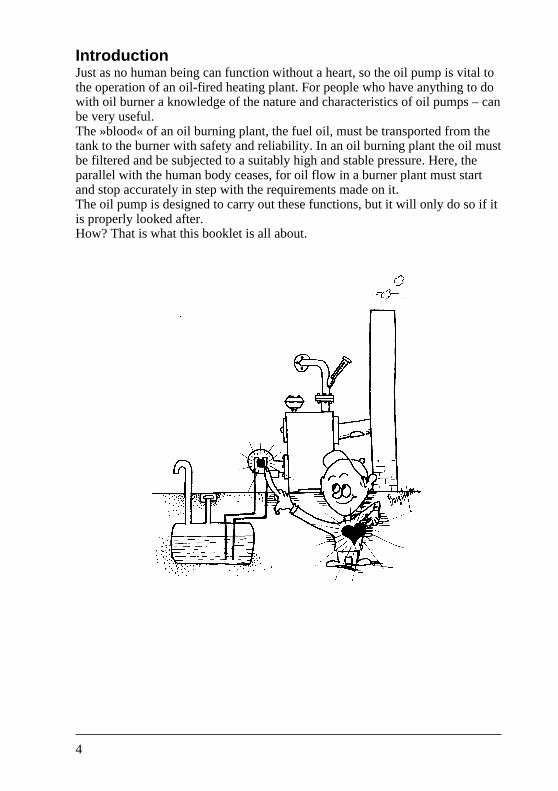
IntroductionJust as no human being can function without a heart, so the oil pump is vital tothe operation of an oil-fired heating plant. For people who have anything to dowith oil burner a knowledge of the nature and characteristics of oil pumps – canbe very useful.The »blood« of an oil burning plant, the fuel oil, must be transported from thetank to the burner with safety and reliability. In an oil burning plant the oil mustbe filtered and be subjected to a suitably high and stable pressure. Here, theparallel with the human body ceases, for oil flow in a burner plant must startand stop accurately in step with the requirements made on it.The oil pump is designed to carry out these functions, but it will only do so if itis properly looked after.How? That is what this booklet is all about.
5
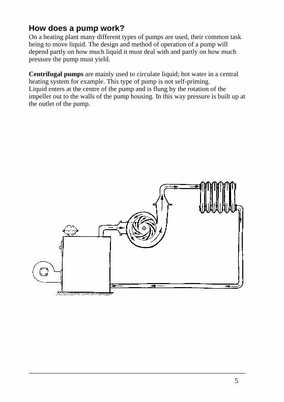
How does a pump work?On a heating plant many different types of pumps are used, their common taskbeing to move liquid. The design and method of operation of a pump willdepend partly on how much liquid it must deal with and partly on how muchpressure the pump must yield.
Centrifugal pumps are mainly used to circulate liquid; hot water in a centralheating system for example. This type of pump is not self-priming.Liquid enters at the centre of the pump and is flung by the rotation of theimpeller out to the walls of the pump housing. In this way pressure is built up atthe outlet of the pump.
6
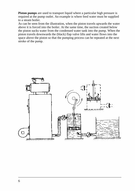
Piston pumps are used to transport liquid where a particular high pressure isrequired at the pump outlet. An example is where feed water must be suppliedto a steam boiler.As can be seen from the illustration, when the piston travels upwards the waterabove it is forced into the boiler. At the same time, the suction created belowthe piston sucks water from the condensed water tank into the pump. When thepiston travels downwards the (black) flap valve lifts and water flows into thespace above the piston so that the pumping process can be repeated at the nextstroke of the pump.
7
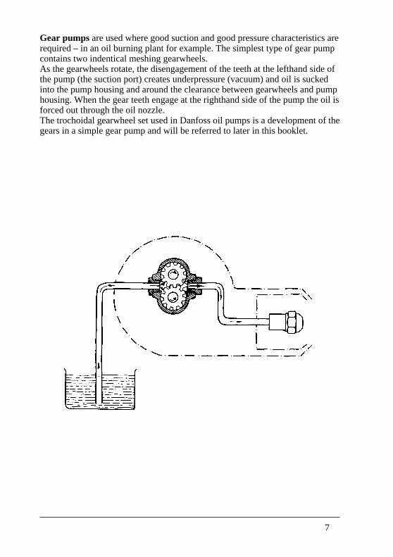
Gear pumps are used where good suction and good pressure characteristics arerequired – in an oil burning plant for example. The simplest type of gear pumpcontains two indentical meshing gearwheels.As the gearwheels rotate, the disengagement of the teeth at the lefthand side ofthe pump (the suction port) creates underpressure (vacuum) and oil is suckedinto the pump housing and around the clearance between gearwheels and pumphousing. When the gear teeth engage at the righthand side of the pump the oil isforced out through the oil nozzle.The trochoidal gearwheel set used in Danfoss oil pumps is a development of thegears in a simple gear pump and will be referred to later in this booklet.
8
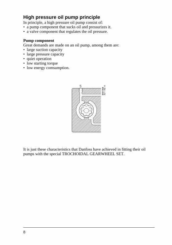
High pressure oil pump principleIn principle, a high pressure oil pump consist of:• a pump component that sucks oil and pressurizes it.• a valve component that regulates the oil pressure.
Pump componentGreat demands are made on an oil pump, among them are:• large suction capacity• large pressure capacity• quiet operation• low starting torque• low energy comsumption.
It is just these characteristics that Danfoss have achieved in fitting their oilpumps with the special TROCHOIDAL GEARWHEEL SET.
9
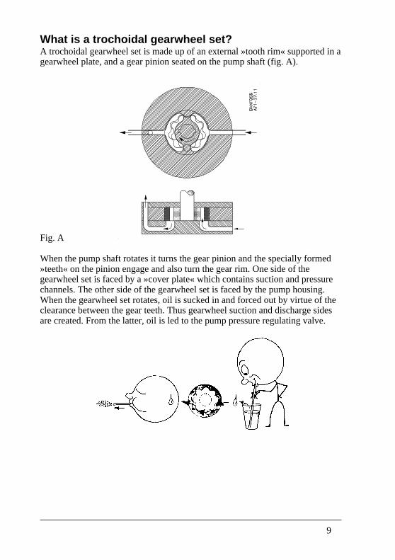
What is a trochoidal gearwheel set?A trochoidal gearwheel set is made up of an external »tooth rim« supported in agearwheel plate, and a gear pinion seated on the pump shaft (fig. A).
Fig. A
When the pump shaft rotates it turns the gear pinion and the specially formed»teeth« on the pinion engage and also turn the gear rim. One side of thegearwheel set is faced by a »cover plate« which contains suction and pressurechannels. The other side of the gearwheel set is faced by the pump housing.When the gearwheel set rotates, oil is sucked in and forced out by virtue of theclearance between the gear teeth. Thus gearwheel suction and discharge sidesare created. From the latter, oil is led to the pump pressure regulating valve.
10
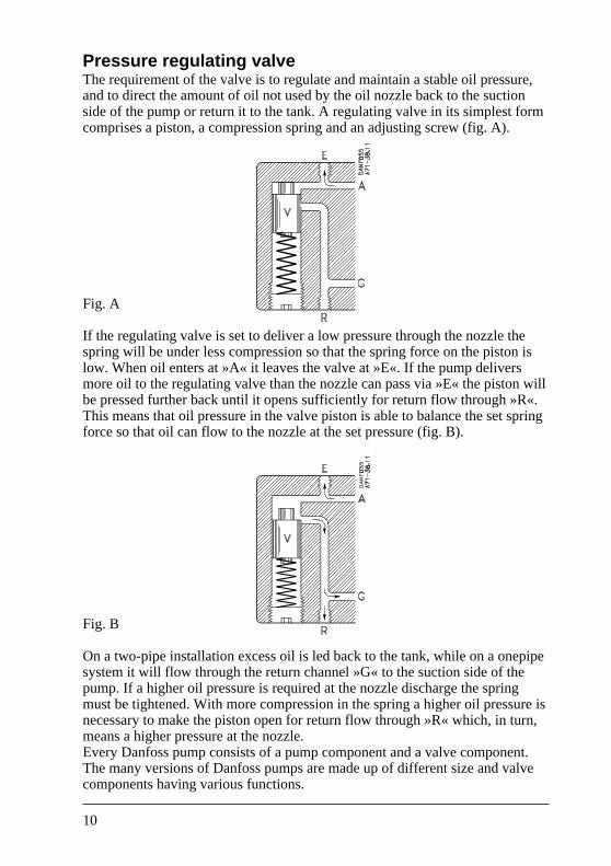
Pressure regulating valveThe requirement of the valve is to regulate and maintain a stable oil pressure,and to direct the amount of oil not used by the oil nozzle back to the suctionside of the pump or return it to the tank. A regulating valve in its simplest formcomprises a piston, a compression spring and an adjusting screw (fig. A).
Fig. A
If the regulating valve is set to deliver a low pressure through the nozzle thespring will be under less compression so that the spring force on the piston islow. When oil enters at »A« it leaves the valve at »E«. If the pump deliversmore oil to the regulating valve than the nozzle can pass via »E« the piston willbe pressed further back until it opens sufficiently for return flow through »R«.This means that oil pressure in the valve piston is able to balance the set springforce so that oil can flow to the nozzle at the set pressure (fig. B).
Fig. B
On a two-pipe installation excess oil is led back to the tank, while on a onepipesystem it will flow through the return channel »G« to the suction side of thepump. If a higher oil pressure is required at the nozzle discharge the springmust be tightened. With more compression in the spring a higher oil pressure isnecessary to make the piston open for return flow through »R« which, in turn,means a higher pressure at the nozzle.Every Danfoss pump consists of a pump component and a valve component.The many versions of Danfoss pumps are made up of different size and valvecomponents having various functions.
11
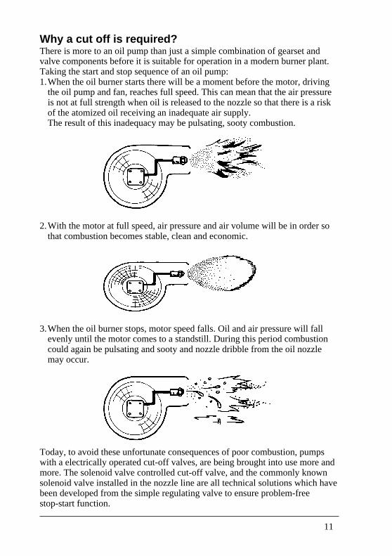
Why a cut off is required?There is more to an oil pump than just a simple combination of gearset andvalve components before it is suitable for operation in a modern burner plant.Taking the start and stop sequence of an oil pump:1.When the oil burner starts there will be a moment before the motor, driving
the oil pump and fan, reaches full speed. This can mean that the air pressureis not at full strength when oil is released to the nozzle so that there is a riskof the atomized oil receiving an inadequate air supply.The result of this inadequacy may be pulsating, sooty combustion.
2.With the motor at full speed, air pressure and air volume will be in order sothat combustion becomes stable, clean and economic.
3.When the oil burner stops, motor speed falls. Oil and air pressure will fallevenly until the motor comes to a standstill. During this period combustioncould again be pulsating and sooty and nozzle dribble from the oil nozzlemay occur.
Today, to avoid these unfortunate consequences of poor combustion, pumpswith a electrically operated cut-off valves, are being brought into use more andmore. The solenoid valve controlled cut-off valve, and the commonly knownsolenoid valve installed in the nozzle line are all technical solutions which havebeen developed from the simple regulating valve to ensure problem-freestop-start function.
12
Why are there different types of oil pumps?Different sizes and types of oil pumps are needed so that different requirementsfor oil volume and correct start-stop operadon can be met.Oil volume is determined by the size and speed of the gearwheel set, while thedifferent start-stop operations depend on the valve design chosen for the pump.The valve can be designed to operate as follows:
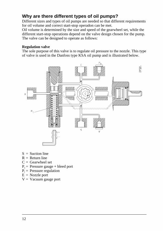
Regulation valveThe sole purpose of this valve is to regulate oil pressure to the nozzle. This typeof valve is used in the Danfoss type KSA oil pump and is illustrated below.
S = Suction lineR = Return lineC = Gearwheel setPs = Pressure gauge + bleed portPl = Pressure regulationE = Nozzle portV = Vacuum gauge port
13
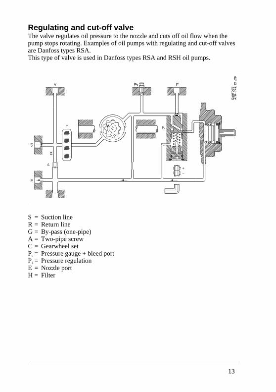
Regulating and cut-off valveThe valve regulates oil pressure to the nozzle and cuts off oil flow when thepump stops rotating. Examples of oil pumps with regulating and cut-off valvesare Danfoss types RSA.This type of valve is used in Danfoss types RSA and RSH oil pumps.
S = Suction lineR = Return lineG = By-pass (one-pipe)A = Two-pipe screwC = Gearwheel setPs = Pressure gauge + bleed portP1= Pressure regulationE = Nozzle portH = Filter
14
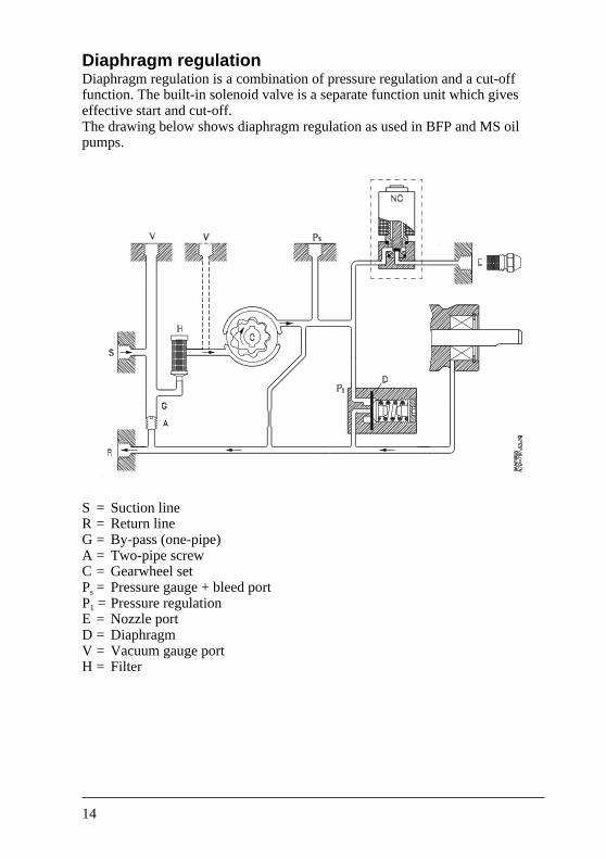
Diaphragm regulationDiaphragm regulation is a combination of pressure regulation and a cut-offfunction. The built-in solenoid valve is a separate function unit which giveseffective start and cut-off.The drawing below shows diaphragm regulation as used in BFP and MS oilpumps.
S = Suction lineR = Return lineG = By-pass (one-pipe)A = Two-pipe screwC = Gearwheel setPs = Pressure gauge + bleed portP1 = Pressure regulationE = Nozzle portD = DiaphragmV = Vacuum gauge portH = Filter
15
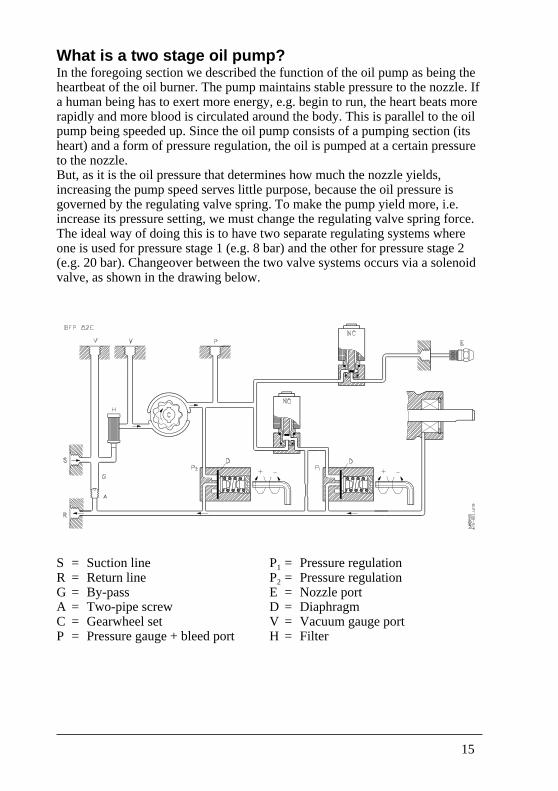
What is a two stage oil pump?In the foregoing section we described the function of the oil pump as being theheartbeat of the oil burner. The pump maintains stable pressure to the nozzle. Ifa human being has to exert more energy, e.g. begin to run, the heart beats morerapidly and more blood is circulated around the body. This is parallel to the oilpump being speeded up. Since the oil pump consists of a pumping section (itsheart) and a form of pressure regulation, the oil is pumped at a certain pressureto the nozzle.But, as it is the oil pressure that determines how much the nozzle yields,increasing the pump speed serves little purpose, because the oil pressure isgoverned by the regulating valve spring. To make the pump yield more, i.e.increase its pressure setting, we must change the regulating valve spring force.The ideal way of doing this is to have two separate regulating systems whereone is used for pressure stage 1 (e.g. 8 bar) and the other for pressure stage 2(e.g. 20 bar). Changeover between the two valve systems occurs via a solenoidvalve, as shown in the drawing below.
S = Suction lineR = Return lineG = By-passA = Two-pipe screwC = Gearwheel setP = Pressure gauge + bleed port
P1 = Pressure regulationP2 = Pressure regulationE = Nozzle portD = DiaphragmV = Vacuum gauge portH = Filter
16
Which units of measurement are used in connectionwith oil pumps?To be able to compare oil pumps, and to be able to select the correct pump for aplant, it is necessary to understand and be familiar with the appropriatetechnical terms when talking oil burners. Through the centuries, people haveused many measuring systems. To compare them is difficult because theconversion from one system to another often involves complicated calculationstogether with a series of conversion factors hard to keep track of.Today, agreement has been reached on an international measuring system, the»SI-system«, a development of the metric system. Since this publication uses SIunits to present technical data, there follows a brief account of the relevant onesand a comparison with units previously used.
17
PressureWhen an oil pump operates, oil is pumped out under a pressure lying within thepressure range of the pump.The SI unit of pressure is the N/m2 (newtons per square metre), also called thepascal (Pa).Since this unit represents a very small pressure (1 kp/cm2 = 100.000 Pa), the baris used extensively.l bar = l00.000 Pa = 100 kPa (kilopascal) = 0.1 MPa (megapascal).
Conversion of bars to other units1 bar = 1.02 kp/cm2 = 0.98 at; in practice the conversion becomes 1 bar =1 kp/cm2 = 1 at = 10 metre water column = 76 cm Hg. (14.5 psi).The pressure referred to up to now is overpressure above atmospheric pressure.To avoid misunderstandings in connection with pressure, some technicalliterature contains an added pressure designation.
pe = effective pressure,i.e. that which is normally taken as being the pressure,(atmospheric pressure = 1 bar pe
pa = absolute pressure.This designation is used when calculating atmospheric pressure.It is seldom used in ordinary technical literature.
18
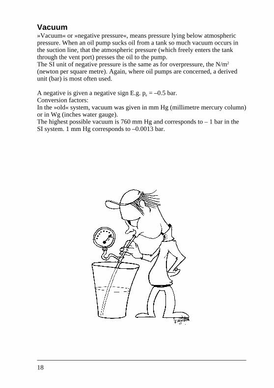
Vacuum»Vacuum« or »negative pressure«, means pressure lying below atmosphericpressure. When an oil pump sucks oil from a tank so much vacuum occurs inthe suction line, that the atmospheric pressure (which freely enters the tankthrough the vent port) presses the oil to the pump.The SI unit of negative pressure is the same as for overpressure, the N/m2
(newton per square metre). Again, where oil pumps are concerned, a derivedunit (bar) is most often used.
A negative is given a negative sign E.g. pe = –0.5 bar.Conversion factors:In the »old« system, vacuum was given in mm Hg (millimetre mercury column)or in Wg (inches water gauge).The highest possible vacuum is 760 mm Hg and corresponds to – 1 bar in theSI system. 1 mm Hg corresponds to –0.0013 bar.
19
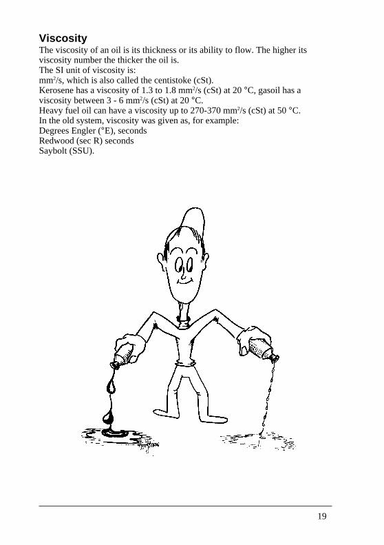
ViscosityThe viscosity of an oil is its thickness or its ability to flow. The higher itsviscosity number the thicker the oil is.The SI unit of viscosity is:mm2/s, which is also called the centistoke (cSt).Kerosene has a viscosity of 1.3 to 1.8 mm2/s (cSt) at 20 °C, gasoil has aviscosity between 3 - 6 mm2/s (cSt) at 20 °C.Heavy fuel oil can have a viscosity up to 270-370 mm2/s (cSt) at 50 °C.In the old system, viscosity was given as, for example:Degrees Engler (°E), secondsRedwood (sec R) secondsSaybolt (SSU).
20
SpeedAn oil pump normally runs at the same speed as the burner motor.The SI unit of speed is min-1.Example: 2800 min-1
This designation is international, unlike previous designations which were oftenabbreviations of a phrase in a particular language:RPM for »revolutions per minute«.
21
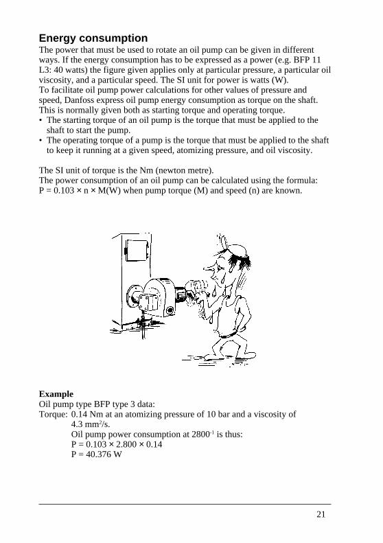
Energy consumptionThe power that must be used to rotate an oil pump can be given in differentways. If the energy consumption has to be expressed as a power (e.g. BFP 11L3: 40 watts) the figure given applies only at particular pressure, a particular oilviscosity, and a particular speed. The SI unit for power is watts (W).To facilitate oil pump power calculations for other values of pressure andspeed, Danfoss express oil pump energy consumption as torque on the shaft.This is normally given both as starting torque and operating torque.• The starting torque of an oil pump is the torque that must be applied to the
shaft to start the pump.• The operating torque of a pump is the torque that must be applied to the shaft
to keep it running at a given speed, atomizing pressure, and oil viscosity.
The SI unit of torque is the Nm (newton metre).The power consumption of an oil pump can be calculated using the formula:P = 0.103 × n × M(W) when pump torque (M) and speed (n) are known.
ExampleOil pump type BFP type 3 data:Torque: 0.14 Nm at an atomizing pressure of 10 bar and a viscosity of
4.3 mm2/s.Oil pump power consumption at 2800-1 is thus:P = 0.103 × 2.800 × 0.14P = 40.376 W
22
CapacityThe amount of oil a pump yields to a nozzle can be expressed in two ways:
Weight per unit of timeThis means that a pump delivers, for example, 25 kilograms of oil during thecourse of 1 hour (25 kg/h).
Volume per unit of timeHere, a pump will deliver for example 45 litres of oil in the course of 1 hour(45 l/h) or, approx. 11.5 - 12 USgal/h.
23
Converting to different units of capacityIf a capacity has to be converted to a different set of units, the first thing toestablish is whether the conversion is volume to volume, or volume to weight,etc.
To illustrate this:
• An oil pump delivers 45 l/h.How much is this in USgal/h?
Both litres and US gallons are units of volume. Therefore the calculation isdirect, given how many litres there are in a US gallon.1 US gallon = 3.785 litres45 litres = 45 ÷ 3.785 = 11.889 or 11.9 USgal/h.
• An oil pump delivers 12 kg/h.How much is this in USgal/h?
As the kilogram is an expression of weight and USgal an expression of volume,direct calculation with a conversion factor (as in the first excample) is notpossible.
First, it is necessary to find the volume of 12 kg of oil (the number of litres).Then the »density« of the oil must be found, i.e. how much 1 litre of oil weighs.If the specific gravity of the oil is 0.83 (at 15 °C), 1 litre weighs 0.83 kg (at 15°C) . Thus, 12 kg oil has a volume of 12 ÷ 0.83 = 14.46 litres.Converting now from 14.46 litres oil to USgal:14.46 ÷ 3.785 = 3.82 USgal.Therefore, 12 kg/h is the same as 3.82 USgal/h, but only with an oil having aspecific gravity of 0.83 (at 15 °C).
24
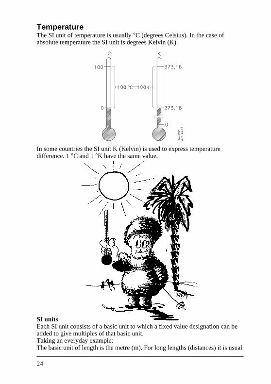
TemperatureThe SI unit of temperature is usually °C (degrees Celsius). In the case ofabsolute temperature the SI unit is degrees Kelvin (K).
In some countries the SI unit K (Kelvin) is used to express temperaturedifference. 1 °C and 1 °K have the same value.
SI unitsEach SI unit consists of a basic unit to which a fixed value designation can beadded to give multiples of that basic unit.Taking an everyday example:The basic unit of length is the metre (m). For long lengths (distances) it is usual
25
to use kilometre (km). In other words, the basic unit »metre« has been prefixedwith »kilo«, which means the total unit now designates 1000 metre.To give small lengths the millimetre (mm) can be used. Here, the basic unit»metre« has been prefixed with »milli«, which is a way of expressing 1/l000 of ametre.
Other common multiples of basic units can be seen in the table below.
Designation Name Multiple Example
G giga 109 (1.000.000.000) 1 gigacalorie = 1 GcalM mega 106 (1.000.000) 1 megawatt = 1 MWk kilo 103 (1.000) 1 kilometre = 1 kmh hecto 102 (100) 1 hektogram = 1 hgda deca 101 (10) 1 decanewton = 1 daN– – 1 1 metre = 1 Md deci 10–1 (1/10) 1 decilitre = 1 dlc centi 10–2 (1/100) 1 centimetre = 1 cmm milli 10–3 (1/1000) 1 millimetre = 1 mmµ micro 10–6 (1/1.000.000) 1 microampere = 1 µA
26
The oil pump in the installation
Page
Relationship between tank andburner – suction height/suction length 28
How to select the correct pipe diameter and pipe length 30
What devices ought to be used in the suction line 31
How various resistances in the suction line affect the pump 32
Why use one-pipe or two-pipe system 33
How to change over a Danfoss oil pump from one-pipeto two-pipe operation 34
When and how must the pump be bled 35
27
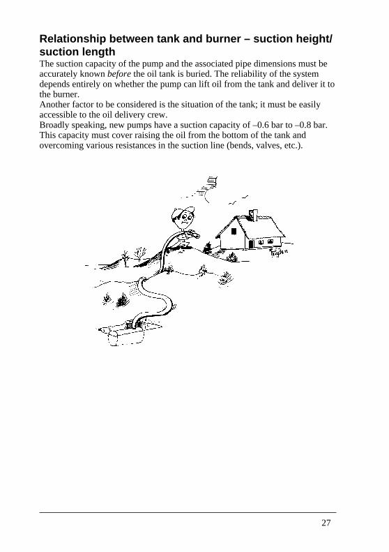
Relationship between tank and burner – suction height/suction lengthThe suction capacity of the pump and the associated pipe dimensions must beaccurately known before the oil tank is buried. The reliability of the systemdepends entirely on whether the pump can lift oil from the tank and deliver it tothe burner.Another factor to be considered is the situation of the tank; it must be easilyaccessible to the oil delivery crew.Broadly speaking, new pumps have a suction capacity of –0.6 bar to –0.8 bar.This capacity must cover raising the oil from the bottom of the tank andovercoming various resistances in the suction line (bends, valves, etc.).
28
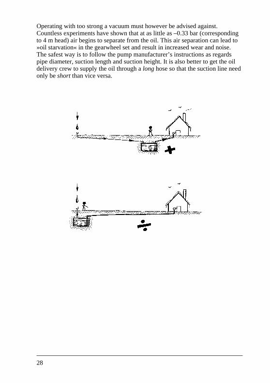
Operating with too strong a vacuum must however be advised against.Countless experiments have shown that at as little as –0.33 bar (correspondingto 4 m head) air begins to separate from the oil. This air separation can lead to»oil starvation« in the gearwheel set and result in increased wear and noise.The safest way is to follow the pump manufacturer’s instructions as regardspipe diameter, suction length and suction height. It is also better to get the oildelivery crew to supply the oil through a long hose so that the suction line needonly be short than vice versa.
29
How to select the correct pipe diameter and pipe lengthSince oil burner reliability is dependent on the capacity of the oil pump to suckoil from the tank and deliver it to the burner, the instructions supplied by themanufacturers of the oil pump regarding pipe layout, pipe diameter and pipelength should be followed – always.
To be able to determine the correct pipe diameter and length, the followingmust be known:• Oil viscosity. This is usually given in Centistokes (cSt) or in degrees sec.
Redwood at a given temperature.• Height difference between the lowest oil level in the tank and the suction port
of the pump, in metres.• Total suction length, in metres.• The various resistances involved arising from valves, filters, bends, etc. in the
suction line. Suction line tables from pump manufacturers will in most casestake account of a certain number of valves and bends.
• Maximum oil volume per hour to be handled by the pipe layout.
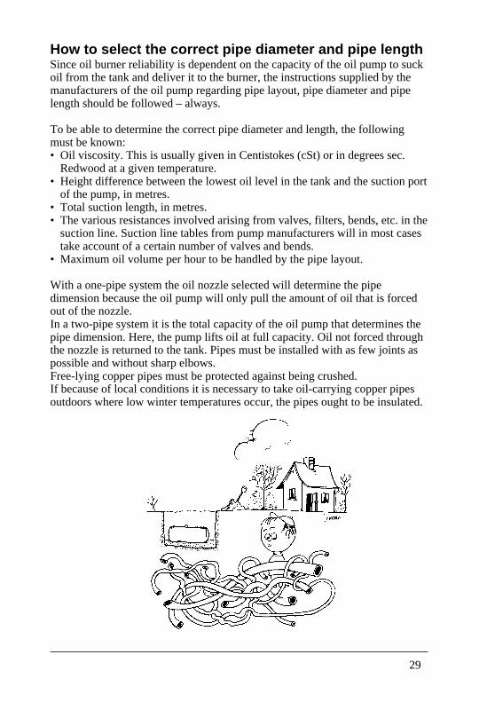
With a one-pipe system the oil nozzle selected will determine the pipedimension because the oil pump will only pull the amount of oil that is forcedout of the nozzle.In a two-pipe system it is the total capacity of the oil pump that determines thepipe dimension. Here, the pump lifts oil at full capacity. Oil not forced throughthe nozzle is returned to the tank. Pipes must be installed with as few joints aspossible and without sharp elbows.Free-lying copper pipes must be protected against being crushed.If because of local conditions it is necessary to take oil-carrying copper pipesoutdoors where low winter temperatures occur, the pipes ought to be insulated.
30
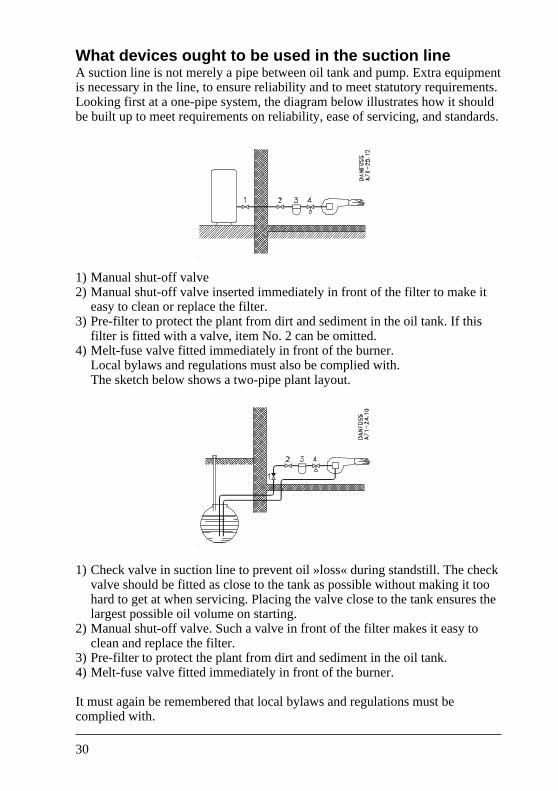
What devices ought to be used in the suction lineA suction line is not merely a pipe between oil tank and pump. Extra equipmentis necessary in the line, to ensure reliability and to meet statutory requirements.Looking first at a one-pipe system, the diagram below illustrates how it shouldbe built up to meet requirements on reliability, ease of servicing, and standards.
1) Manual shut-off valve2) Manual shut-off valve inserted immediately in front of the filter to make it
easy to clean or replace the filter.3) Pre-filter to protect the plant from dirt and sediment in the oil tank. If this
filter is fitted with a valve, item No. 2 can be omitted.4) Melt-fuse valve fitted immediately in front of the burner.
Local bylaws and regulations must also be complied with.The sketch below shows a two-pipe plant layout.
1) Check valve in suction line to prevent oil »loss« during standstill. The checkvalve should be fitted as close to the tank as possible without making it toohard to get at when servicing. Placing the valve close to the tank ensures thelargest possible oil volume on starting.
2) Manual shut-off valve. Such a valve in front of the filter makes it easy toclean and replace the filter.
3) Pre-filter to protect the plant from dirt and sediment in the oil tank.4) Melt-fuse valve fitted immediately in front of the burner.
It must again be remembered that local bylaws and regulations must becomplied with.
31
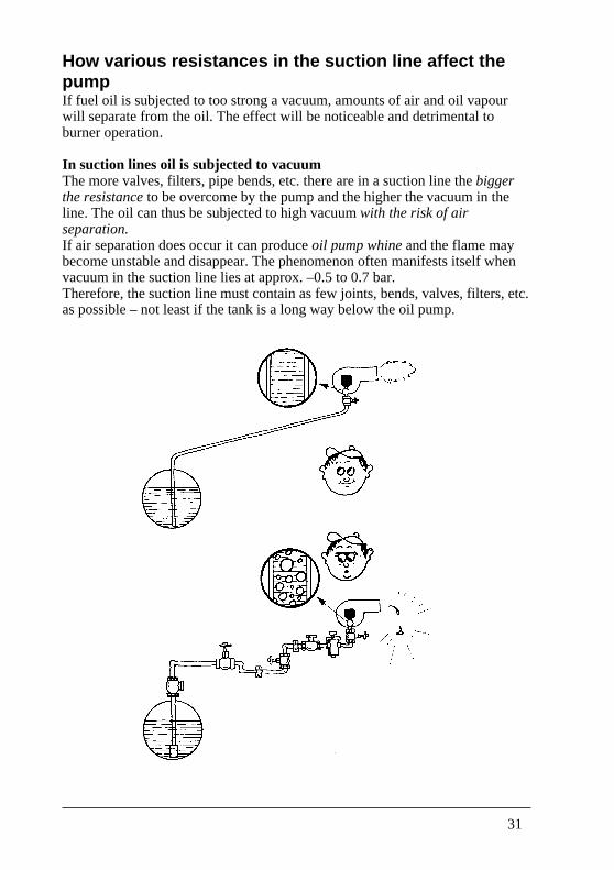
How various resistances in the suction line affect thepumpIf fuel oil is subjected to too strong a vacuum, amounts of air and oil vapourwill separate from the oil. The effect will be noticeable and detrimental toburner operation.
In suction lines oil is subjected to vacuumThe more valves, filters, pipe bends, etc. there are in a suction line the biggerthe resistance to be overcome by the pump and the higher the vacuum in theline. The oil can thus be subjected to high vacuum with the risk of airseparation.If air separation does occur it can produce oil pump whine and the flame maybecome unstable and disappear. The phenomenon often manifests itself whenvacuum in the suction line lies at approx. –0.5 to 0.7 bar.Therefore, the suction line must contain as few joints, bends, valves, filters, etc.as possible – not least if the tank is a long way below the oil pump.
32
Why use one-pipe or two-pipe systems?Of course it is cheaper and easier to connect an oil tank to an oil burner with asingle pipe, but the most reliable system will be one that follows currentEuropean practice.
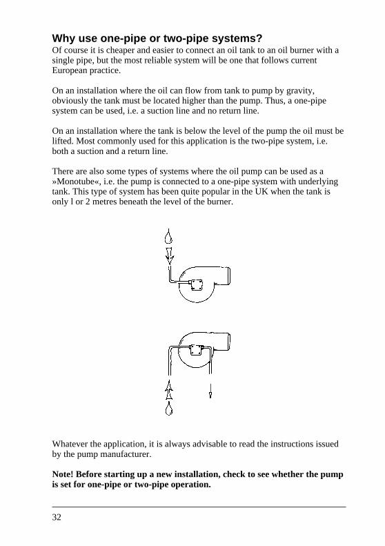
On an installation where the oil can flow from tank to pump by gravity,obviously the tank must be located higher than the pump. Thus, a one-pipesystem can be used, i.e. a suction line and no return line.
On an installation where the tank is below the level of the pump the oil must belifted. Most commonly used for this application is the two-pipe system, i.e.both a suction and a return line.
There are also some types of systems where the oil pump can be used as a»Monotube«, i.e. the pump is connected to a one-pipe system with underlyingtank. This type of system has been quite popular in the UK when the tank isonly l or 2 metres beneath the level of the burner.
Whatever the application, it is always advisable to read the instructions issuedby the pump manufacturer.
Note! Before starting up a new installation, check to see whether the pumpis set for one-pipe or two-pipe operation.
33
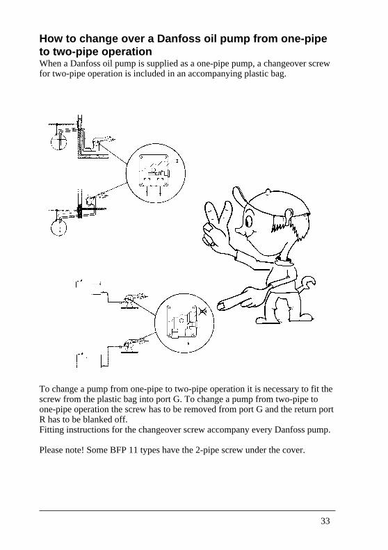
How to change over a Danfoss oil pump from one-pipeto two-pipe operationWhen a Danfoss oil pump is supplied as a one-pipe pump, a changeover screwfor two-pipe operation is included in an accompanying plastic bag.
To change a pump from one-pipe to two-pipe operation it is necessary to fit thescrew from the plastic bag into port G. To change a pump from two-pipe toone-pipe operation the screw has to be removed from port G and the return portR has to be blanked off.Fitting instructions for the changeover screw accompany every Danfoss pump.
Please note! Some BFP 11 types have the 2-pipe screw under the cover.
34
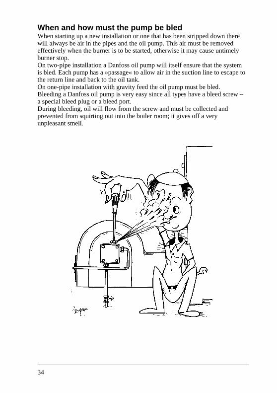
When and how must the pump be bledWhen starting up a new installation or one that has been stripped down therewill always be air in the pipes and the oil pump. This air must be removedeffectively when the burner is to be started, otherwise it may cause untimelyburner stop.On two-pipe installation a Danfoss oil pump will itself ensure that the systemis bled. Each pump has a »passage« to allow air in the suction line to escape tothe return line and back to the oil tank.On one-pipe installation with gravity feed the oil pump must be bled.Bleeding a Danfoss oil pump is very easy since all types have a bleed screw –a special bleed plug or a bleed port.During bleeding, oil will flow from the screw and must be collected andprevented from squirting out into the boiler room; it gives off a veryunpleasant smell.
35
Questions that can arise when working with oil pumps
Page
What do the pump instructions contain? 37
What happens if the wrong tools are used? 38
How can the condition of the pump be checked? 39
What ought to be checked before a complaintis made about the oil pump? 40
What significance have the oil characteristics? 41
Will the pump be ruined if it is run on paraffin? 42
Why is it necessary to watch for water in the oil? 43
How should the oil filters be looked after? 45
What happens if the suction and return linesare swapped over? 46
What happens if the two-pipe screws is fitted incorrectly? 47
Should the pump suction side be subjected to pressure? 49
What are the risks in do-it-yourself pump dismantling? 50
Why is it impossible to buy replacement gearwheel sets? 51
What can happen if pump pressure is regulatedwithout the use of a pressure gauge? 52
How high an oil pressure can a pumpwithstand before damage occurs? 53
What happens if a vacuum gauge is fitted onthe delivery side of the pump? 54
How can vacuum increase if the pumphas not been tampered with? 55
Can two pumps be allowed to draw on the same suction line? 56
What about drawing oil from several tanks for one burner? 57
Nipples must not leak – what is the method of sealing them? 58
Why is it necessary to start a newly-installed oil burnerfour or five times before the pump becomes primed? 59
36
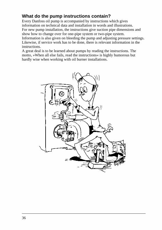
What do the pump instructions contain?Every Danfoss oil pump is accompanied by instructions which givesinformation on technical data and installation in words and illustrations.For new pump installation, the instructions give suction pipe dimensions andshow how to change over for one-pipe system or two-pipe system.Information is also given on bleeding the pump and adjusting pressure settings.Likewise, if service work has to be done, there is relevant information in theinstructions.A great deal is to be learned about pumps by reading the instructions. Themotto, »When all else fails, read the instructions« is highly humorous buthardly wise when working with oil burner installations.
37
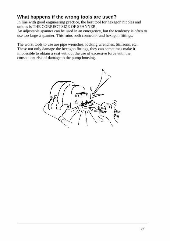
What happens if the wrong tools are used?In line with good engineering practice, the best tool for hexagon nipples andunions is THE CORRECT SIZE OF SPANNER.An adjustable spanner can be used in an emergency, but the tendency is often touse too large a spanner. This ruins both connector and hexagon fittings.
The worst tools to use are pipe wrenches, locking wrenches, Stillsons, etc.These not only damage the hexagon fittings, they can sometimes make itimpossible to obtain a seat without the use of excessive force with theconsequent risk of damage to the pump housing.
38
How can the condition of the pump be checked?When adjustments are made to an oil burner that has been in operation for someyears the opportunity can be used to check the oil pump whilst the vacuum andpressure gauges are still connected. The method is as follows:First, make a note of the vacuum and oil pressure during normal operation.Next, shut off the suction line by closing the valve fitted in the line (most oftena melt-fuse valve) and check how much vacuum the pump will produce.If when max. vacuum has been reached (–0.5 to 0.7 bar for example) the pumpbegins to whine, open the valve again. A pump can be damaged if run for toolong a period with air which has been separated from the oil under highvacuum.When starting up a system with an empty suction line, and only normal vacuumis involved, the pump can be allowed to run for 5 min with the amount of oilleft in it from factory assembly.Check the pressure producing capacity of the pump by giving the pressureregulating screw a couple of turns to see if the resulting pressure change occurssmoothly.If the pressure capacity of the pump is in order, adjust the pressure back to therequired setting.Note: It is impossible to check the condition of a pump without using thecorrect measuring instruments (vacuum gauge and pressure gauge).
39
What ought to be checked before a complaint is madeabout the oil pump?It is not particularly comfortable when the pump refuses to work on a coldwinter’s day, and quite often the manufacturers of the pump become thesubject of unkind thoughts. However, a few things ought to be checked beforea seemingly hopeless pump is returned, because practical experience showsthat nearly 50% of all pumps returned are in fact without defect.
For example, check to see:• if there is oil in the tank.• that the pump shaft rotates. The coupling between pump and motor (perhaps
the fan pulley) may need replacing.• that the motor rotates in the right direction.• that the pump speed is correct.• if the shut-off valve on the suction line is closed, (it must be open).• if the check valve on the suction side is stuck or fitted the wrong way round.• if the suction and return lines have been swapped over.• if the suction line has been crushed, (copper pipe installation).• that the pump is set appropriately for one-pipe or two-pipe operation.• that the pump capacity corresponds to the capacity of the burner.• if there are leaks in the suction line, (use a clear plastic hose between line
and pump) • if the pump can suck, (use a vacuum gauge).• if the pump can produce pressure, (use a pressure gauge).• that the filter on the suction side is clean and the filter housing does not leak.• that the various pipes are connected to the correct pump ports.• if there is water in the oil. Smear water indicating paste on the dip stick.
Insert the dip stick in the oil tank. If water is present the paste will changecolour. If it does change colour, the tank needs cleaning out!
40
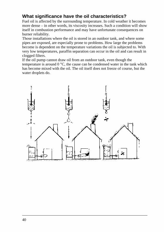
What significance have the oil characteristics?Fuel oil is affected by the surrounding temperature. In cold weather it becomesmore dense – in other words, its viscosity increases. Such a condition will showitself in combustion performance and may have unfortunate consequences onburner reliability.Those installations where the oil is stored in an outdoor tank, and where somepipes are exposed, are especially prone to problems. How large the problemsbecome is dependent on the temperature variations the oil is subjected to. Withvery low temperatures, paraffin separation can occur in the oil and can result inclogged filters.If the oil pump cannot draw oil from an outdoor tank, even though thetemperature is around 0 °C, the cause can be condensed water in the tank whichhas become mixed with the oil. The oil itself does not freeze of course, but thewater droplets do.
41
Will the pump be ruined if it is run on paraffin?If the oil tank runs dry, the temptation is to use some other fuel to keep theburner going – paraffin for example. The gas-oil normally used in an oil burneris a little thicker than kerosene (it is more viscous) and the question arises, »cana pump withstand running on thin fuel?«.Purely mechanically, there is nothing to prevent a Danfoss oil pump fromrunning on kerosene instead of normal fuel oil: no damage will ensue. From thepoint of view of combustion however, in certain circumstances there will benoticeable changes because the use of a thinner fuel will change the nozzlecapacity. This means burner readjustment, especially if the thinner fuel is in usefor a prolonged period.
Note: In some countries the use of liquid fuel with a flame point lower than55 °C is not permitted in oil burner installations. Therefore, in thesecountries, using kerosene must be considered an absolute short-termemergency measure.
42
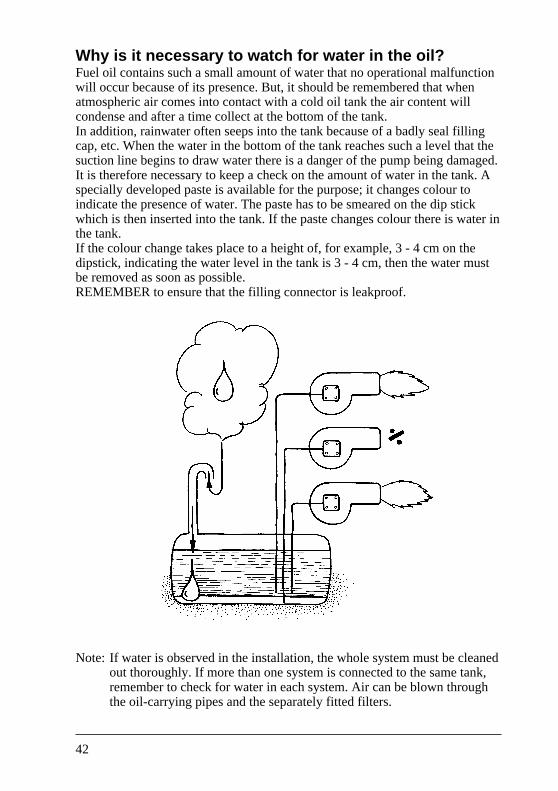
Why is it necessary to watch for water in the oil?Fuel oil contains such a small amount of water that no operational malfunctionwill occur because of its presence. But, it should be remembered that whenatmospheric air comes into contact with a cold oil tank the air content willcondense and after a time collect at the bottom of the tank.In addition, rainwater often seeps into the tank because of a badly seal fillingcap, etc. When the water in the bottom of the tank reaches such a level that thesuction line begins to draw water there is a danger of the pump being damaged.It is therefore necessary to keep a check on the amount of water in the tank. Aspecially developed paste is available for the purpose; it changes colour toindicate the presence of water. The paste has to be smeared on the dip stickwhich is then inserted into the tank. If the paste changes colour there is water inthe tank.If the colour change takes place to a height of, for example, 3 - 4 cm on thedipstick, indicating the water level in the tank is 3 - 4 cm, then the water mustbe removed as soon as possible.REMEMBER to ensure that the filling connector is leakproof.
Note: If water is observed in the installation, the whole system must be cleanedout thoroughly. If more than one system is connected to the same tank,remember to check for water in each system. Air can be blown throughthe oil-carrying pipes and the separately fitted filters.
43
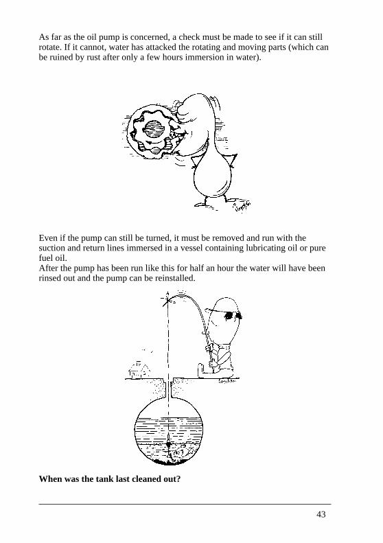
As far as the oil pump is concerned, a check must be made to see if it can stillrotate. If it cannot, water has attacked the rotating and moving parts (which canbe ruined by rust after only a few hours immersion in water).
Even if the pump can still be turned, it must be removed and run with thesuction and return lines immersed in a vessel containing lubricating oil or purefuel oil.After the pump has been run like this for half an hour the water will have beenrinsed out and the pump can be reinstalled.
When was the tank last cleaned out?
44
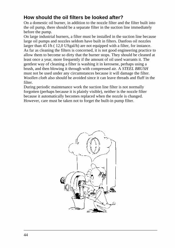
How should the oil filters be looked after?On a domestic oil burner, in addition to the nozzle filter and the filter built intothe oil pump, there should be a separate filter in the suction line immediatelybefore the pump.On large industrial burners, a filter must be installed in the suction line becauselarge oil pumps and nozzles seldom have built in filters. Danfoss oil nozzleslarger than 45 l/h ( 12,0 USgal/h) are not equipped with a filter, for instance.As far as cleaning the filters is concerned, it is not good engineering practice toallow them to become so dirty that the burner stops. They should be cleaned atleast once a year, more frequently if the amount of oil used warrants it. Thegentlest way of cleaning a filter is washing it in kerosene, perhaps using abrush, and then blowing it through with compressed air. A STEEL BRUSHmust not be used under any circumstances because it will damage the filter.Woollen cloth also should be avoided since it can leave threads and fluff in thefilter.During periodic maintenance work the suction line filter is not normallyforgotten (perhaps because it is plainly visible), neither is the nozzle filterbecause it automatically becomes replaced when the nozzle is changed.However, care must be taken not to forget the built-in pump filter.
45
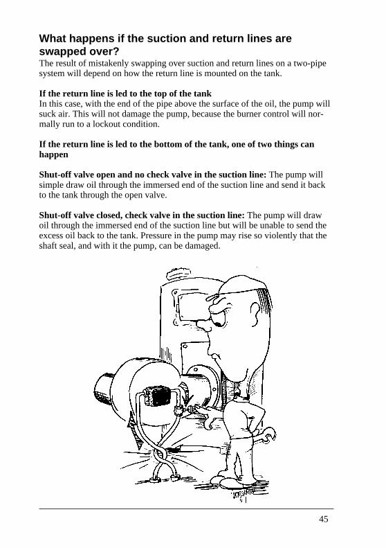
What happens if the suction and return lines areswapped over?The result of mistakenly swapping over suction and return lines on a two-pipesystem will depend on how the return line is mounted on the tank.
If the return line is led to the top of the tankIn this case, with the end of the pipe above the surface of the oil, the pump willsuck air. This will not damage the pump, because the burner control will nor-mally run to a lockout condition.
If the return line is led to the bottom of the tank, one of two things canhappen
Shut-off valve open and no check valve in the suction line: The pump willsimple draw oil through the immersed end of the suction line and send it backto the tank through the open valve.
Shut-off valve closed, check valve in the suction line: The pump will drawoil through the immersed end of the suction line but will be unable to send theexcess oil back to the tank. Pressure in the pump may rise so violently that theshaft seal, and with it the pump, can be damaged.
46
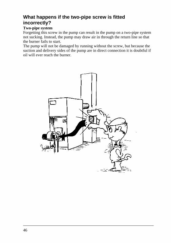
What happens if the two-pipe screw is fittedincorrectly?Two-pipe systemForgetting this screw in the pump can result in the pump on a two-pipe systemnot sucking. Instead, the pump may draw air in through the return line so thatthe burner fails to start.The pump will not be damaged by running without the screw, but because thesuction and delivery sides of the pump are in direct connection it is doubtful ifoil will ever reach the burner.
47
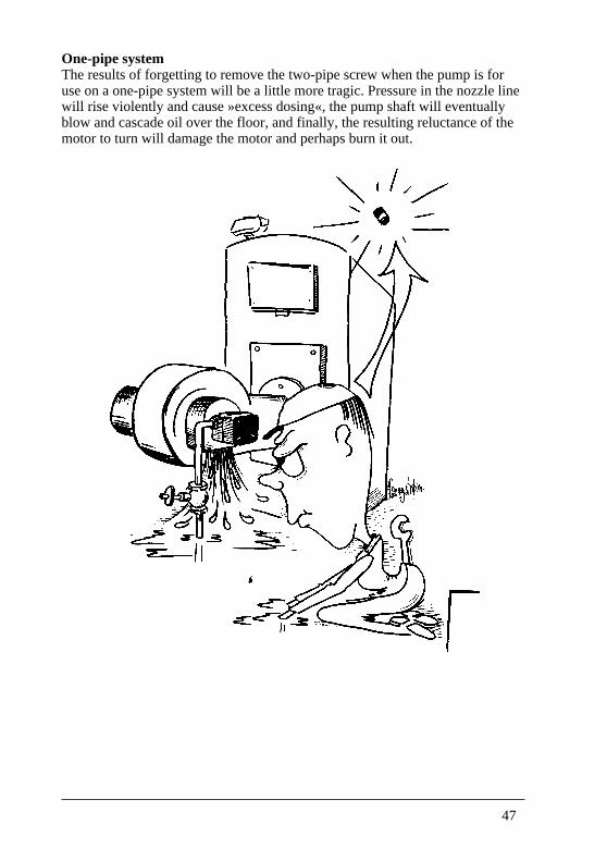
One-pipe systemThe results of forgetting to remove the two-pipe screw when the pump is foruse on a one-pipe system will be a little more tragic. Pressure in the nozzle linewill rise violently and cause »excess dosing«, the pump shaft will eventuallyblow and cascade oil over the floor, and finally, the resulting reluctance of themotor to turn will damage the motor and perhaps burn it out.
48
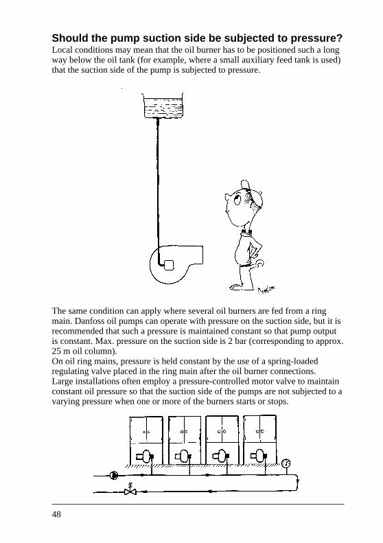
Should the pump suction side be subjected to pressure?Local conditions may mean that the oil burner has to be positioned such a longway below the oil tank (for example, where a small auxiliary feed tank is used)that the suction side of the pump is subjected to pressure.
The same condition can apply where several oil burners are fed from a ringmain. Danfoss oil pumps can operate with pressure on the suction side, but it isrecommended that such a pressure is maintained constant so that pump outputis constant. Max. pressure on the suction side is 2 bar (corresponding to approx.25 m oil column).On oil ring mains, pressure is held constant by the use of a spring-loadedregulating valve placed in the ring main after the oil burner connections.Large installations often employ a pressure-controlled motor valve to maintainconstant oil pressure so that the suction side of the pumps are not subjected to avarying pressure when one or more of the burners starts or stops.
49
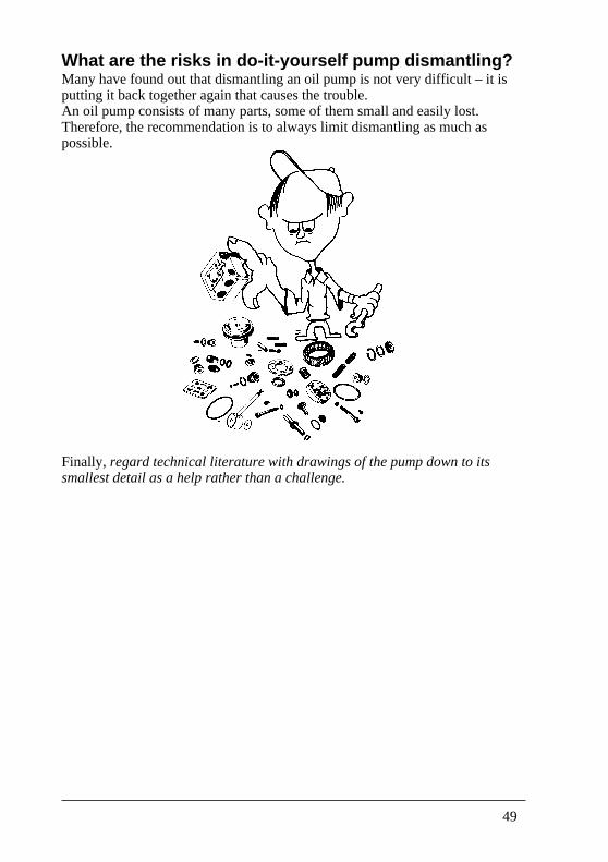
What are the risks in do-it-yourself pump dismantling?Many have found out that dismantling an oil pump is not very difficult – it isputting it back together again that causes the trouble.An oil pump consists of many parts, some of them small and easily lost.Therefore, the recommendation is to always limit dismantling as much aspossible.
Finally, regard technical literature with drawings of the pump down to itssmallest detail as a help rather than a challenge.
50
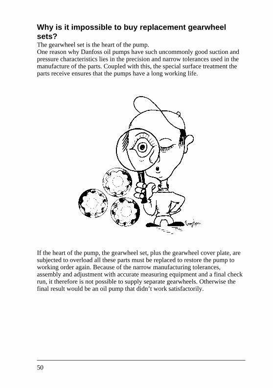
Why is it impossible to buy replacement gearwheelsets?The gearwheel set is the heart of the pump.One reason why Danfoss oil pumps have such uncommonly good suction andpressure characteristics lies in the precision and narrow tolerances used in themanufacture of the parts. Coupled with this, the special surface treatment theparts receive ensures that the pumps have a long working life.
If the heart of the pump, the gearwheel set, plus the gearwheel cover plate, aresubjected to overload all these parts must be replaced to restore the pump toworking order again. Because of the narrow manufacturing tolerances,assembly and adjustment with accurate measuring equipment and a final checkrun, it therefore is not possible to supply separate gearwheels. Otherwise thefinal result would be an oil pump that didn’t work satisfactorily.
51
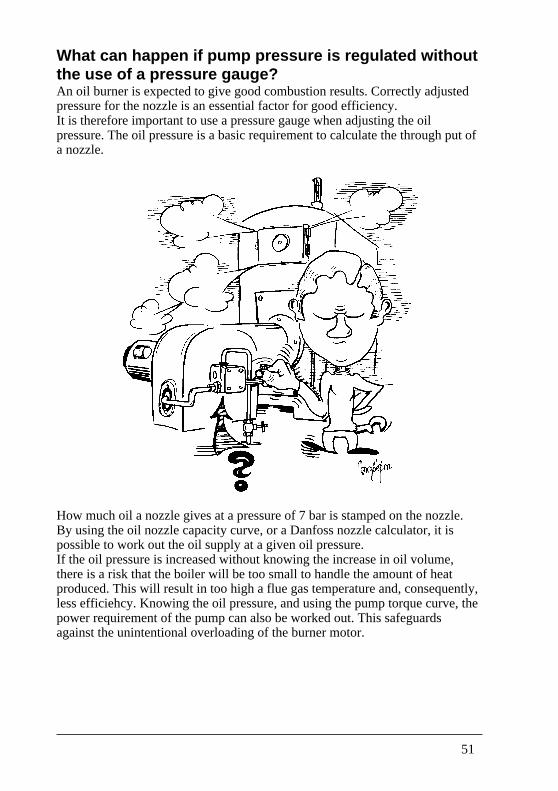
What can happen if pump pressure is regulated withoutthe use of a pressure gauge?An oil burner is expected to give good combustion results. Correctly adjustedpressure for the nozzle is an essential factor for good efficiency.It is therefore important to use a pressure gauge when adjusting the oilpressure. The oil pressure is a basic requirement to calculate the through put ofa nozzle.
How much oil a nozzle gives at a pressure of 7 bar is stamped on the nozzle.By using the oil nozzle capacity curve, or a Danfoss nozzle calculator, it ispossible to work out the oil supply at a given oil pressure.If the oil pressure is increased without knowing the increase in oil volume,there is a risk that the boiler will be too small to handle the amount of heatproduced. This will result in too high a flue gas temperature and, consequently,less efficiehcy. Knowing the oil pressure, and using the pump torque curve, thepower requirement of the pump can also be worked out. This safeguardsagainst the unintentional overloading of the burner motor.
52
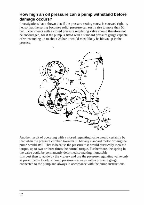
How high an oil pressure can a pump withstand beforedamage occurs?Investigations have shown that if the pressure setting screw is screwed right in,i.e. so that the spring becomes solid, pressure can easily rise to more than 50bar. Experiments with a closed pressure regulating valve should therefore notbe encouraged, for if the pump is fitted with a standard pressure gauge capableof withstanding up to about 25 bar it would most likely be blown up in theprocess.
Another result of operating with a closed regulating valve would certainly bethat when the pressure climbed towards 50 bar any standard motor driving thepump would stall. That is because the pressure rise would drastically increasetorque, up to two or three times the normal torque. Furthermore, the spring inthe valve could be permanently deformed so making it unusable.It is best then to abide by the »rules« and use the pressure regulating valve onlyas prescribed – to adjust pump pressure – always with a pressure gaugeconnected to the pump and always in accordance with the pump instructions.
53
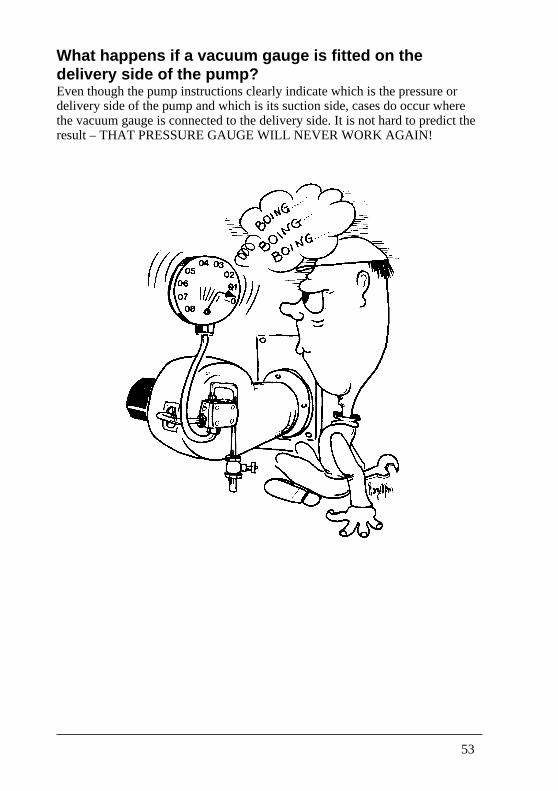
What happens if a vacuum gauge is fitted on thedelivery side of the pump?Even though the pump instructions clearly indicate which is the pressure ordelivery side of the pump and which is its suction side, cases do occur wherethe vacuum gauge is connected to the delivery side. It is not hard to predict theresult – THAT PRESSURE GAUGE WILL NEVER WORK AGAIN!

54
How can vacuum increase if the pump has not beentampered with?The operational reliability of an oil burning installation is entirely dependent onwhether the pump is able to draw oil from the tank. The higher the vacuumbecomes, the more unreliable becomes the oil suction. Therefore, because apump will not deliver oil even though it has good suction there may be astraightforward reason and it should not be sent for repair until a series ofpoints have been checked, i.e.• is the shut-off valve open?• is the pump filter clean?• is the separate filter clean?• does the check valve stick?• has the check valve been fitted the wrong way round?• has the suction line been crushed?• is the oil too cold?• is there an obstruction in the suction line?
When resistance in a suction line rises, the vacuum rises. When vacuumreaches somewhere around –0.4 to –0.5 bar, air will be separated from the oiland the pump will begin to whine. A further rise in vacuum may, sooner orlater, stop the oil supply.As a rule, a high rate of air separation will show itself by violent fluctuations onthe pressure gauge, perhaps on the vacuum gauge too.
55
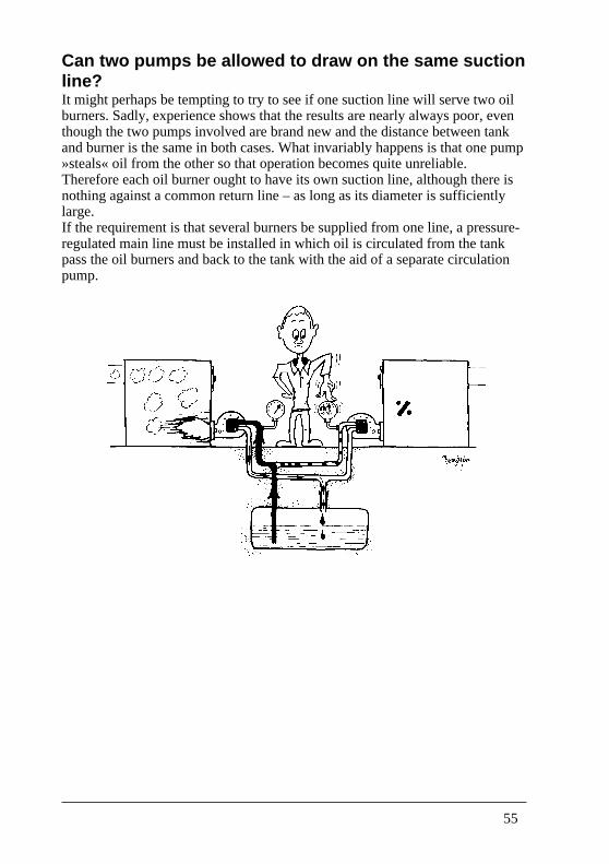
Can two pumps be allowed to draw on the same suctionline?It might perhaps be tempting to try to see if one suction line will serve two oilburners. Sadly, experience shows that the results are nearly always poor, eventhough the two pumps involved are brand new and the distance between tankand burner is the same in both cases. What invariably happens is that one pump»steals« oil from the other so that operation becomes quite unreliable.Therefore each oil burner ought to have its own suction line, although there isnothing against a common return line – as long as its diameter is sufficientlylarge.If the requirement is that several burners be supplied from one line, a pressure-regulated main line must be installed in which oil is circulated from the tankpass the oil burners and back to the tank with the aid of a separate circulationpump.
56
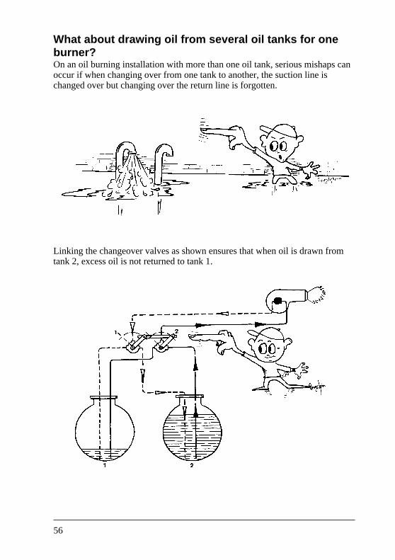
What about drawing oil from several oil tanks for oneburner?On an oil burning installation with more than one oil tank, serious mishaps canoccur if when changing over from one tank to another, the suction line ischanged over but changing over the return line is forgotten.
Linking the changeover valves as shown ensures that when oil is drawn fromtank 2, excess oil is not returned to tank 1.
57
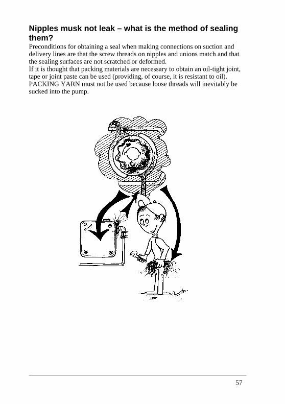
Nipples musk not leak – what is the method of sealingthem?Preconditions for obtaining a seal when making connections on suction anddelivery lines are that the screw threads on nipples and unions match and thatthe sealing surfaces are not scratched or deformed.If it is thought that packing materials are necessary to obtain an oil-tight joint,tape or joint paste can be used (providing, of course, it is resistant to oil).PACKING YARN must not be used because loose threads will inevitably besucked into the pump.
58
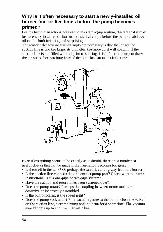
Why is it often necessary to start a newly-installed oilburner four or five times before the pump becomesprimed?For the technician who is not used to the starting-up routine, the fact that it maybe necessary to carry out four or five start attempts before the pump »catches«oil can be both irritating and surprising.The reason why several start attempts are necessary is that the longer thesuction line is and the larger its diameter, the more air it will contain. If thesuction line is not filled with oil prior to starting, it is left to the pump to drawthe air out before catching hold of the oil. This can take a little time.
Even if everything seems to be exactly as it should, there are a number ofuseful checks that can be made if the frustration becomes too great.• Is there oil in the tank? Or perhaps the tank lies a long way from the burner.• Is the suction line connected to the correct pump port? Check with the pump
instructions. Is it a one-pipe or two-pipe system?• Have the suction and return lines been swapped over?• Does the pump rotate? Perhaps the coupling between motor and pump is
defective or incorrectly assembled.• If the pump rotates, is the speed right?• Does the pump suck at all? Fit a vacuum gauge to the pump, close the valve
on the suction line, start the pump and let it run for a short time. The vacuumshould come up to about –0.5 to –0.7 bar.
59
Pump problems
Page
Pump will not rotate 61
Pump will not suck 62
Pump pressure cannot be regulated 63
Pump pressure oscillates 64
Pump oil flow cut-off ineffective 65
No oil from the pump 66
More oil than normal from the pump 67
Oil loss from the pump during standstill 68
Pump overheats 69
Pump whines or makes a crackling noise 70
Voltage drop 71
60
Pump will not rotateThe familiar sound an oil burner makes when it is in operation is reassuring, tothe extent that no sound for a prolonged period indicates that something iswrong. In order to find the reason, the following points may be checked.After having made all the normal checks – oil starvation, closed or blockedvalves, air in the system, dirty filter and nozzle, low pressure and vacuum, etc.– without success, the feeling might be that the pump should be sent back forrepair. Before doing so however, there is one more thing to check:Is the pump in fact being driven by the motor coupling/fan pulley?The coupling or pulley could be defective or could have worked itself loose.Such a malfunction does not necessarily indicate its presence by undue noise.
61
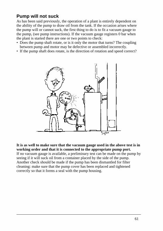
Pump will not suckAs has been said previously, the operation of a plant is entirely dependent onthe ability of the pump to draw oil from the tank. If the occasion arises wherethe pump will or cannot suck, the first thing to do is to fit a vacuum gauge tothe pump, (see pump instructions). If the vacuum gauge registers 0 bar whenthe plant is started there are one or two points to check:• Does the pump shaft rotate, or is it only the motor that turns? The coupling
between pump and motor may be defective or assembled incorrectly.• If the pump shaft does rotate, is the direction of rotation and speed correct?
It is as well to make sure that the vacuum gauge used in the above test is inworking order and that it is connected to the appropriate pump port.If no vacuum gauge is available, a preliminary test can be made on the pump byseeing if it will suck oil from a container placed by the side of the pump.Another check should be made if the pump has been dismantled for filtercleaning: make sure that the pump cover has been replaced and tightenedcorrectly so that it forms a seal with the pump housing.
62
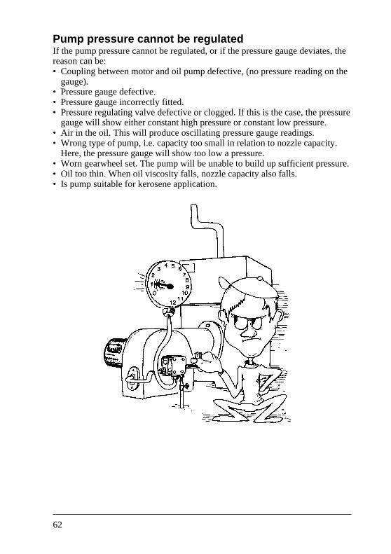
Pump pressure cannot be regulatedIf the pump pressure cannot be regulated, or if the pressure gauge deviates, thereason can be:• Coupling between motor and oil pump defective, (no pressure reading on the
gauge).• Pressure gauge defective.• Pressure gauge incorrectly fitted.• Pressure regulating valve defective or clogged. If this is the case, the pressure
gauge will show either constant high pressure or constant low pressure.• Air in the oil. This will produce oscillating pressure gauge readings.• Wrong type of pump, i.e. capacity too small in relation to nozzle capacity.
Here, the pressure gauge will show too low a pressure.• Worn gearwheel set. The pump will be unable to build up sufficient pressure.• Oil too thin. When oil viscosity falls, nozzle capacity also falls.• Is pump suitable for kerosene application.
63
Pump pressure oscillatesPump pressure variations can produce poor combustion since the oil volume aswell as the atomizing pattern will change.
Possible reasons are:• Air in the oil as a consequence of leaks or too high a vacuum in the suction
line, (half-closed shut-off valve, blocked filter, blocked check valve in thesuction line, crushed suction line, etc.).
• Dirt in the pump pressure regulating valve.• Defective spring in the pump pressure valve.• Pump/motor coupling slip, i.e. speed variations.
Note: On an installation with a ring main where several burners are suppliedfrom one pump, pressure variations can occur if the pressure regulatingvalve (which maintains constant pressure in the ring main) is defective.(See section »Should the pump suction side be subjected to pressure?«).
64
Pump nozzle cut-off ineffectiveAn oil burner starts and stops about ten or twelve thousand times a year. If thenozzle cut-off is ineffective the boiler will become very sooty internally. Oilpumps having a cut-off function are designed to cut off oil to the nozzle whenrevolutions per minute are still high, so that combustion air from the fan issufficient to ensure a soot-free stop.Cut-off or closing is effected by a solenoid valve installed in the nozzle line orincorporated in the pump.
The reasons for poor cut-off can be as follows:• Air build-up in the nozzle line, or perhaps in the nozzle or between nozzle
and nozzle holder.• Dirt in the hydraulic cut-off valve, or a defective spring/diaphragm.• Dirt in the nozzle line solenoid valve.
65
No oil from the pumpBurner mounted on boiler, piping carefully installed and connected, water on,wiring complete, oil tank full, and..........nothing!
After five or six attempts to start the plant, irritation must give way to a logicalfault-finding procedure to find out why not a drop of oil is reaching the nozzle:• Open the valve on the section line.• Bleed the pump in accordance with the instructions.• Fit pressure gauge and vacuum gauge to the pump to check pressure and
vacuum.• Check the coupling between motor and pump.• Start the burner and check the pump direction of rotation.• Check the pump installation (one-pipe or two-pipe system). If there is still no
sign of oil at the nozzle, check:• to see that the suction and return lines have not been swapped over.• that the solenoid valve operates, or if appropriate, why it does not operate.• that the oil nozzle is not blocked.• that the check valve in the suction line is not the wrong way round.• that the suction line does not leak and that it has not been crushed flat.
Note: Oil may have been supplied to the nozzle at some time during thisprocedure and may lie unburnt in the combustion chamber. Subsequentignition will cause this oil to evaporate and may lead to a near-explosivestart.
REMEMBER to vent the boiler if a number of unsuccessful starts havebeen attempted without oil ignition. This is even more important whenthe boiler is hot because of the higher rate of oil evaporation than with acold boiler.
66
More oil than normal from the pumpPerhaps the oil supply is greater than is considered normal, i.e. the flameappears to be larger than expected; check the following:• Oil pressure. It may be too high as a consequence of attempts to make
adjustments without using a pressure gauge.• Pump regulating valve. If this is blocked by dirt too high a pressure may be
created which, in turn, may lead to too much oil at the nozzle.• The oil nozzle. Perhaps the wrong size has been fitted, e.g. a 5.0 USgal/h
nozzle instead of a 0.5 USgal/h nozzle.
67
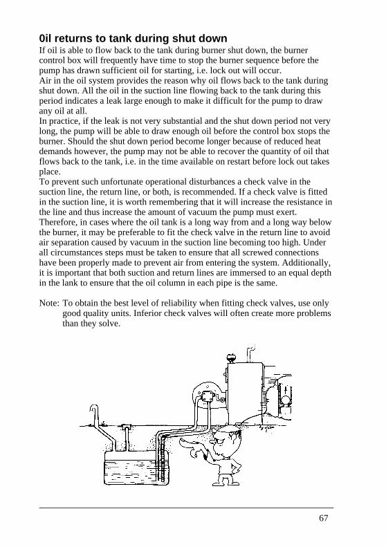
0il returns to tank during shut downIf oil is able to flow back to the tank during burner shut down, the burnercontrol box will frequently have time to stop the burner sequence before thepump has drawn sufficient oil for starting, i.e. lock out will occur.Air in the oil system provides the reason why oil flows back to the tank duringshut down. All the oil in the suction line flowing back to the tank during thisperiod indicates a leak large enough to make it difficult for the pump to drawany oil at all.In practice, if the leak is not very substantial and the shut down period not verylong, the pump will be able to draw enough oil before the control box stops theburner. Should the shut down period become longer because of reduced heatdemands however, the pump may not be able to recover the quantity of oil thatflows back to the tank, i.e. in the time available on restart before lock out takesplace.To prevent such unfortunate operational disturbances a check valve in thesuction line, the return line, or both, is recommended. If a check valve is fittedin the suction line, it is worth remembering that it will increase the resistance inthe line and thus increase the amount of vacuum the pump must exert.Therefore, in cases where the oil tank is a long way from and a long way belowthe burner, it may be preferable to fit the check valve in the return line to avoidair separation caused by vacuum in the suction line becoming too high. Underall circumstances steps must be taken to ensure that all screwed connectionshave been properly made to prevent air from entering the system. Additionally,it is important that both suction and return lines are immersed to an equal depthin the lank to ensure that the oil column in each pipe is the same.
Note: To obtain the best level of reliability when fitting check valves, use onlygood quality units. Inferior check valves will often create more problemsthan they solve.
68
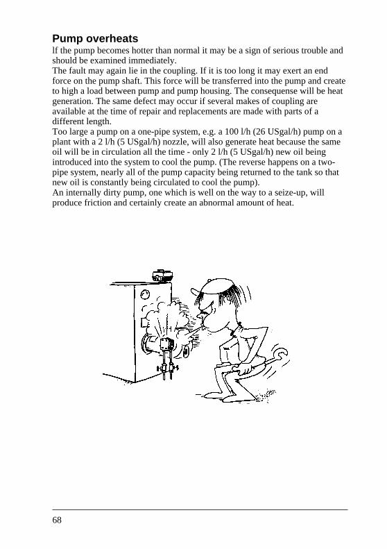
Pump overheatslf the pump becomes hotter than normal it may be a sign of serious trouble andshould be examined immediately.The fault may again lie in the coupling. If it is too long it may exert an endforce on the pump shaft. This force will be transferred into the pump and createto high a load between pump and pump housing. The consequense will be heatgeneration. The same defect may occur if several makes of coupling areavailable at the time of repair and replacements are made with parts of adifferent length.Too large a pump on a one-pipe system, e.g. a 100 l/h (26 USgal/h) pump on aplant with a 2 l/h (5 USgal/h) nozzle, will also generate heat because the sameoil will be in circulation all the time - only 2 l/h (5 USgal/h) new oil beingintroduced into the system to cool the pump. (The reverse happens on a two-pipe system, nearly all of the pump capacity being returned to the tank so thatnew oil is constantly being circulated to cool the pump).An internally dirty pump, one which is well on the way to a seize-up, willproduce friction and certainly create an abnormal amount of heat.
69
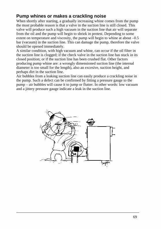
Pump whines or makes a crackling noiseWhen shortly after starting, a gradually increasing whine comes from the pumpthe most probable reason is that a valve in the suction line is still closed. Thisvalve will produce such a high vacuum in the suction line that air will separatefrom the oil and the pump will begin to shriek in protest. Depending to someextent on temperature and viscosity, the pump will begin to whine at about –0.5bar (vacuum) in the suction line. This can damage the pump, therefore the valveshould be opened immediately.A similar condition, with high vacuum and whine, can occur if the oil filter inthe suction line is clogged; if the check valve in the suction line has stuck in itsclosed position; or if the suction line has been crushed flat. Other factorsproducing pump whine are: a wrongly dimensioned suction line (the internaldiameter is too small for the length), also an excesive, suction height, andperhaps dirt in the suction line.Air bubbles from a leaking suction line can easily produce a crackling noise inthe pump. Such a defect can be confirmed by fitting a pressure gauge to thepump – air bubbles will cause it to jump or flutter. In other words: low vacuumand a jittery pressure gauge indicate a leak in the suction line.
70
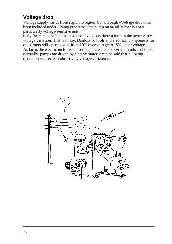
Voltage dropVoltage supply varies from region to region, but although »Voltage drop« hasbeen included under »Pump problems« the pump on an oil burner is not aparticularly voltage-sensitive unit.Only for pumps with built-in solenoid valves is there a limit to the permissiblevoltage variation. That is to say, Danfoss controls and electrical components foroil burners will operate with from 10% over voltage to 15% under voltage.As far as the electric motor is concerned, there are also certain limits and since,normally, pumps are driven by electric motor it can be said that oil pumpoperation is affected indirectly by voltage variations.


Danfoss can accept no responsibility for possible errors in catalogues, brochures and other printed material. Danfoss reserves the right to alter its products without notice. This also applies toproducts already on order provided that such alterations can be made without subsequential changes being necessary in specifications already agreed.All trademarks in this material are property of the respective companies. Danfoss and the Danfoss logotype are trademarks of Danfoss A/S. All rights reserved.
520F0073 – DKBG.PG.010.A7.02 Produced by Danfoss G1 advertising agency 00.06 FO-Bi.LG