
Facts worth knowing about nozzles - Danfoss
44
Facts worth knowing about Oil nozzles
Transcript of Facts worth knowing about nozzles - Danfoss

Facts worth knowing about
Oil nozzles


1
Facts worth knowing about Danfoss oil nozzlesPage
Contents Oil nozzles and the complete oil-burning plant 3What is there to know about oil nozzles? 4What has a Danfoss oil nozzle to offer? 5How is a Danfoss oil nozzle built up? 6How does a Danfoss oil nozzle work? 7What must be done to the oil to make it burn? 8But how does the combustion itself take place? 9What does clean economic combustion mean? 10What effect has atomizing pressure? 11What effect has oil quality and temperature? 12What effect has air supply on the oil burner? 13Where must the oil nozzle be located? 15For how long can an oil nozzle be used? 16How should an oil nozzle be handled? 17Can an oil nozzle be cleaned? 18What do the numbers and letters on the nozzle mean? 19How is the correct oil nozzle chosen? 20Is it possible to compare oil nozzles of different makes 21What causes an oil nozzle to drip? 22What makes the flame lopsided? 23What is the cause of no oil from the nozzle? 24What causes oil coke on the nozzleand ignition electrodes? 25Why “shooting start” in the flame? 26What produces a greasy malodorous deposit inthe boiler and how can it be removed? 27Why does soot form in the flame? 28What causes the oil to ignite with a bang? 29What can be wrong if there is no flame? 30What causes leakage between oil nozzleand nozzle fixture? 31Can the nozzle be the reason for the flue-gastemperature being too high? 32Can the nozzle cause too low a flue-gastemperature? 33What makes the flame too long? 34What causes oil and coke to collect around nozzleand combustion head? 35Why does nozzle output suddenly begin to vary? 36What to do with old, worn out nozzles? 37Nozzle capacities 39

2

3
Oil nozzles and the complete oil-burning plantA complete oil-burning plant begins at the oil tank filling connection andends at the chimney pipe.Every one of the many parts which go to make up the plant must functionso that the plant is CLEAN, STABLE and ECONOMIC.Hidden from view at the heart of the plant is a small interesting gadgetwhich looks more like a very nicely done pipe plug than anything else –this is the oil nozzle.The oil nozzle plays a vital role in combustion and it is quite impossible toget CLEAN, STABLE and ECONOMIC plant operation if it is nothandled correctly.A technician in the oil burner field will, naturally – or to put it morestrongly – necessarily, know about the function of the oil nozzle and of itssignificance in the combustion sequence.Fortunately, to learn about oil nozzles it is not neccessary to read for ascience degree. Instead, more convenient means are to hand – a momentor two, somewhere to relax, and this book.

4
What is there to know about oil nozzles?In general, the answer to this question is, ”A great deal!” However, what is”necessary” knowledge depends on whether it is the manufacture of oilnozzles or their use is concerned.
To make good oil nozzles, a very comprehensive knowledge of thefollowing is necessary:• Characteristics of fuel oil and combustion.• The nature of atomizing and spray patterns.• Oil-burning plant design.• Precision machine work.
On top of all this, a manufacturer must have a department where necessaryand very critical inspection and testing of the finished nozzles takes place.Nozzles play an important part in the everyday work of oilburnertechnicians. That is why it is important for them to follow manufacturers-instructions. In this way they will exploit to the full all the knowledge andexperience the manufacturer is passing on through those instructions to gainclean, stable and economic combustion.Even today, there are a great many plants running with poor combustionbecause of incomplete knowledge of oil nozzles. Such a lack of knowledgecan have other unfortunate consequences; attemps are sometimes made tocure faults by changing the nozzle when in reality the faults have nothing todo with the nozzle.
5
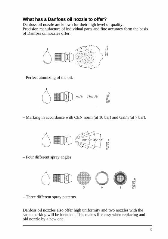
What has a Danfoss oil nozzle to offer?Danfoss oil nozzle are known for their high level of quality.Precision manufacture of individual parts and fine accuracy form the basisof Danfoss oil nozzles offer:
– Perfect atomizing of the oil.
– Marking in accordance with CEN norm (at 10 bar) and Gal/h (at 7 bar).
– Four different spray angles.
– Three different spray patterns.
Danfoss oil nozzles also offer high uniformity and two nozzles with thesame marking will be identical. This makes life easy when replacing andold nozzle by a new one.
6
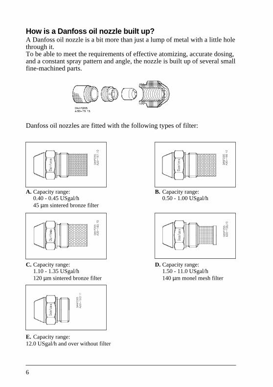
How is a Danfoss oil nozzle built up?A Danfoss oil nozzle is a bit more than just a lump of metal with a little holethrough it.To be able to meet the requirements of effective atomizing, accurate dosing,and a constant spray pattern and angle, the nozzle is built up of several smallfine-machined parts.
Danfoss oil nozzles are fitted with the following types of filter:
A. Capacity range: B. Capacity range:0.40 - 0.45 USgal/h 0.50 - 1.00 USgal/h45 µm sintered bronze filter
C. Capacity range: D. Capacity range:1.10 - 1.35 USgal/h 1.50 - 11.0 USgal/h120 µm sintered bronze filter 140 µm monel mesh filter
E. Capacity range:12.0 USgal/h and over without filter
7
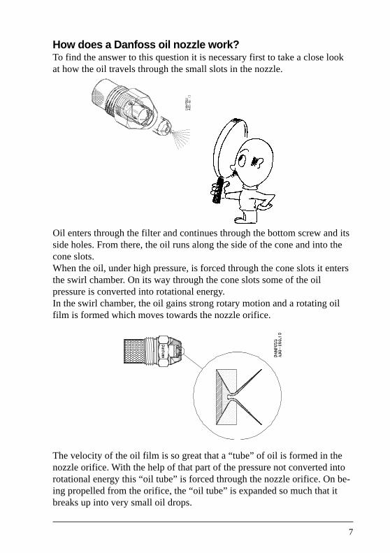
How does a Danfoss oil nozzle work?To find the answer to this question it is necessary first to take a close lookat how the oil travels through the small slots in the nozzle.
Oil enters through the filter and continues through the bottom screw and itsside holes. From there, the oil runs along the side of the cone and into thecone slots.When the oil, under high pressure, is forced through the cone slots it entersthe swirl chamber. On its way through the cone slots some of the oilpressure is converted into rotational energy.In the swirl chamber, the oil gains strong rotary motion and a rotating oilfilm is formed which moves towards the nozzle orifice.
The velocity of the oil film is so great that a “tube” of oil is formed in thenozzle orifice. With the help of that part of the pressure not converted intorotational energy this “oil tube” is forced through the nozzle orifice. On be-ing propelled from the orifice, the “oil tube” is expanded so much that itbreaks up into very small oil drops.
8
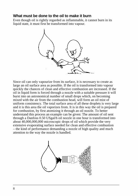
What must be done to the oil to make it burnEven though oil is rightly regarded as inflammable, it cannot burn in itsliquid state, it must first be transformed into vapour.
Since oil can only vapourize from its surface, it is necessary to create aslarge an oil surface area as possible. If the oil is transformed into vapourquickly the chances of clean and effective combustion are increased. If theoil in liquid form is forced through a nozzle with a suitable pressure it willburst into an astronomical number of small drops which, on becomingmixed with the air from the combustion head, will form an oil mist ofuniform consistency. The total surface area of all these droplets is very largeand it is this area the oil vaporizes from. It is in this way the oil is preparedfor combustion, by first atomizing it through an oil nozzle. To betterunderstand this process an example can be given: The amount of oil sentthrough a Danfoss 0.50 USgal/h oil nozzle in one hour is transformed intoabout 40,000,000,000 microscopic drops of oil which provide the veryextensive evaporating surface needed for clean and effective combustion– the kind of performance demanding a nozzle of high quality and muchattention to the way the nozzle is handled.

9
But how does the combustion itself take place?The main ingredients of oil are: carbon and
hydrogen
Air contains: oxygen andnitrogen
When oil vapour mixes with the oxygen in the air, in the right proportions,the mixture will burn on ignition and generate heat. At first sight, therewould seem to be few big problems involved in burning a little oil, but thereis more to it than that. The need is for stability, cleanliness and economy; inother words, the oil must be burned with as little excess air as possiblewithout producing soot. To get oil to burn like this assumes, among otherthings, a correct choice of oil nozzle and attention to the way the nozzle ishandled.
Heat Flue gas
Oxygen
Nitrogen
CarbonHydrogen
10
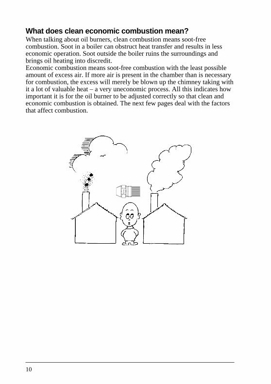
What does clean economic combustion mean?When talking about oil burners, clean combustion means soot-freecombustion. Soot in a boiler can obstruct heat transfer and results in lesseconomic operation. Soot outside the boiler ruins the surroundings andbrings oil heating into discredit.Economic combustion means soot-free combustion with the least possibleamount of excess air. If more air is present in the chamber than is necessaryfor combustion, the excess will merely be blown up the chimney taking withit a lot of valuable heat – a very uneconomic process. All this indicates howimportant it is for the oil burner to be adjusted correctly so that clean andeconomic combustion is obtained. The next few pages deal with the factorsthat affect combustion.
11
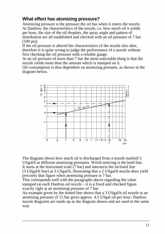
What effect has atomizing pressure?Atomizing pressure is the pressure the oil has when it enters the nozzle.At Danfoss, the characteristics of the nozzle, i.e. how much oil it yieldsper hour, the size of the oil droplets, the spray angle and pattern ofdistribution are all established and checked with an oil pressure of 7 bar(100 psi).If the oil pressure is altered the characteristics of the nozzle also alter,therefore it is quite wrong to judge the performance of a nozzle withoutfirst checking the oil pressure with a reliable gauge.At an oil pressure of more than 7 bar the most noticeable thing is that thenozzle yields more than the amount which is stamped on it.Oil consumption is thus dependent on atomizing pressure, as shown in thediagram below.
The diagram shows how much oil is discharged from a nozzle marked 3USgal/h at different atomizing pressures. Worth noticing is the bold line.It starts at the horizontal scale (7 bar) and intersects the inclined line(3 USgal/h line) at 3 USgal/h, illustrating that a 2 USgal/h nozzle does yieldprecisely that figure when atomizing pressure is 7 bar.This corresponds well with the paragraphs above regarding the valuestamped on each Danfoss oil nozzle – it is a fixed and checked figureexactly right at an atomizing pressure of 7 bar.An example given by the dotted line shows that a 3 USgal/h oil nozzle at anatomizing pressure of 15 bar gives approx. 4.5 USgal oil per hour. Danfossnozzle diagrams are made up as the diagram shown and are used in the sameway.

12
What effect has oil quality and temperature?The characteristics of the oil nozzle are factory-checked with a standardfuel oil having closely fixed flow properties (viscosity) measured at 20°C.Viscosity is given in the oil nozzle leaflets.When oil is cooled down it becomes thicker – its viscosity rises. If it iswarmed up, oil becomes thinner and its viscosity drops.The fuel oil normally supplied for oil burners has a viscosity which scarcelyalters for temperature changes between 0°C and 30°C. Combustion willtherefore not alter significantly as long as oil temperature is held betweenthese figures.On plant where the oil tank may be exposed to temperatures lower than0°C certain problems can occur. An outdoor tank for example can easilybecome quite cold so that the oil in it thickens enough to change theatomizing pattern of the nozzle.A change such as this will result partly in the oil droplets becoming biggerso making the flame longer and more ”sluggish” in burning, and partly inan increase in nozzle output which will usually mean that combustionbecomes sooty.For these reasons, oil tanks which are outside and above ground, and allthe exposed pipes, ought to be insulated to avoid problems in wintertime.
Note!Any water in an exposed oil tank (condensation perhaps) is an extrahazard. When temperatures drop to around freezing point the water willturn into ice and may block the oil pipe.
13
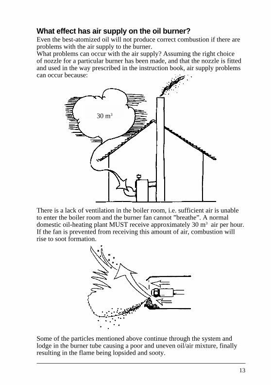
What effect has air supply on the oil burner?Even the best-atomized oil will not produce correct combustion if there areproblems with the air supply to the burner.What problems can occur with the air supply? Assuming the right choiceof nozzle for a particular burner has been made, and that the nozzle is fittedand used in the way prescribed in the instruction book, air supply problemscan occur because:
There is a lack of ventilation in the boiler room, i.e. sufficient air is unableto enter the boiler room and the burner fan cannot ”breathe”. A normaldomestic oil-heating plant MUST receive approximately 30 m3 air per hour.If the fan is prevented from receiving this amount of air, combustion willrise to soot formation.
Some of the particles mentioned above continue through the system andlodge in the burner tube causing a poor and uneven oil/air mixture, finallyresulting in the flame being lopsided and sooty.
30 m3

14
The oil burner fan works something like a vacuum cleaner. This means thatair sucked in carries dust particles, hairs from the dog, etc., etc.Gradually, the fan inlet becomes partly blocked, the amount of air receivedgets smaller and smaller, and the flame again produces more and more soot.
An unstable draught can also have an unfortunate effect on the air supply.
Put simply: it is most annoying to have otherwise good combustion ruinedjust because the air supply for it is not correct.
15
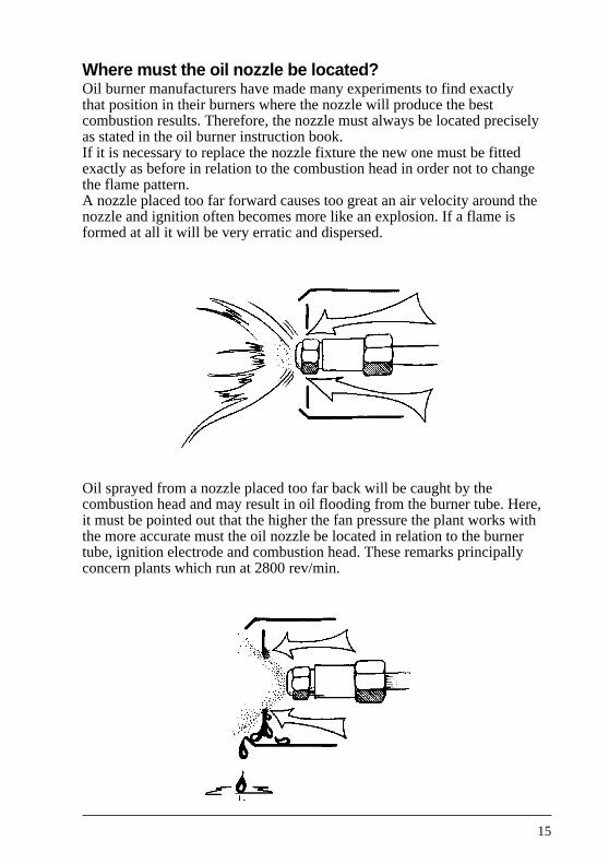
Where must the oil nozzle be located?Oil burner manufacturers have made many experiments to find exactlythat position in their burners where the nozzle will produce the bestcombustion results. Therefore, the nozzle must always be located preciselyas stated in the oil burner instruction book.If it is necessary to replace the nozzle fixture the new one must be fittedexactly as before in relation to the combustion head in order not to changethe flame pattern.A nozzle placed too far forward causes too great an air velocity around thenozzle and ignition often becomes more like an explosion. If a flame isformed at all it will be very erratic and dispersed.
Oil sprayed from a nozzle placed too far back will be caught by thecombustion head and may result in oil flooding from the burner tube. Here,it must be pointed out that the higher the fan pressure the plant works withthe more accurate must the oil nozzle be located in relation to the burnertube, ignition electrode and combustion head. These remarks principallyconcern plants which run at 2800 rev/min.
16
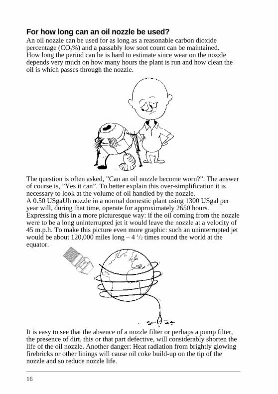
For how long can an oil nozzle be used?An oil nozzle can be used for as long as a reasonable carbon dioxidepercentage (CO2%) and a passably low soot count can be maintained.How long the period can be is hard to estimate since wear on the nozzledepends very much on how many hours the plant is run and how clean theoil is which passes through the nozzle.
The question is often asked, ”Can an oil nozzle become worn?”. The answerof course is, ”Yes it can”. To better explain this over-simplification it isnecessary to look at the volume of oil handled by the nozzle.A 0.50 USgaUh nozzle in a normal domestic plant using 1300 USgal peryear will, during that time, operate for approximately 2650 hours.Expressing this in a more picturesque way: if the oil coming from the nozzlewere to be a long uninterrupted jet it would leave the nozzle at a velocity of45 m.p.h. To make this picture even more graphic: such an uninterrupted jetwould be about 120,000 miles long – 4 1/2 times round the world at theequator.
It is easy to see that the absence of a nozzle filter or perhaps a pump filter,the presence of dirt, this or that part defective, will considerably shorten thelife of the oil nozzle. Another danger: Heat radiation from brightly glowingfirebricks or other linings will cause oil coke build-up on the tip of thenozzle and so reduce nozzle life.
17
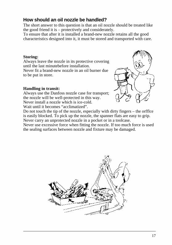
How should an oil nozzle be handled?The short answer to this question is that an oil nozzle should be treated likethe good friend it is – protectively and considerately.To ensure that after it is installed a brand-new nozzle retains all the goodcharacteristics designed into it, it must be stored and transported with care.
Storing:Always leave the nozzle in its protective coveringuntil the last minutebefore installation.Never fit a brand-new nozzle in an oil burner dueto be put in store.
Handling in transit:Always use the Danfoss nozzle case for transport;the nozzle will be well-protected in this way.Never install a nozzle which is ice-cold.Wait until it becomes “acclimatized”.Do not touch the tip of the nozzle, especially with dirty fingers – the orfflceis easily blocked. To pick up the nozzle, the spanner flats are easy to grip.Never carry an unprotected nozzle in a pocket or in a toolcase.Never use excessive force when fitting the nozzle. If too much force is usedthe sealing surfaces between nozzle and fixture may be damaged.
18
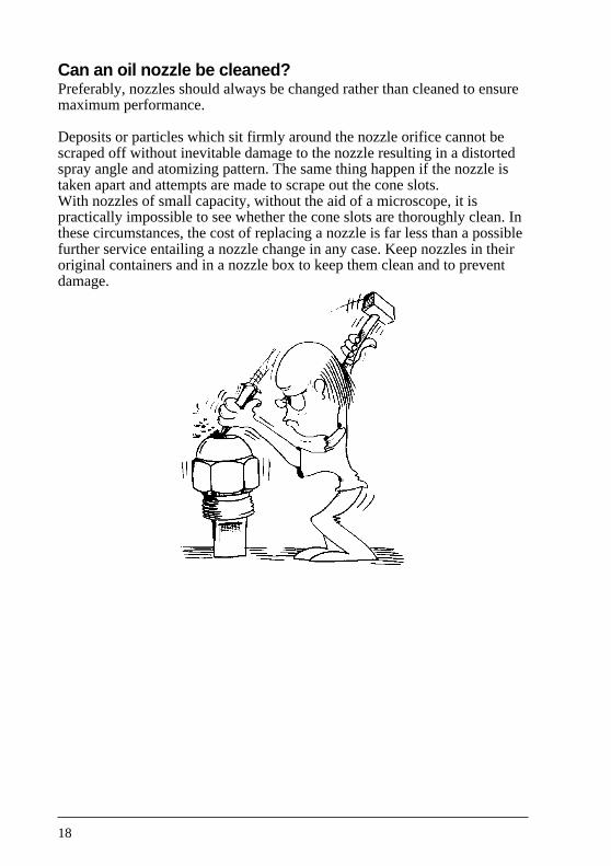
Can an oil nozzle be cleaned?Preferably, nozzles should always be changed rather than cleaned to ensuremaximum performance.
Deposits or particles which sit firmly around the nozzle orifice cannot bescraped off without inevitable damage to the nozzle resulting in a distortedspray angle and atomizing pattern. The same thing happen if the nozzle istaken apart and attempts are made to scrape out the cone slots.With nozzles of small capacity, without the aid of a microscope, it ispractically impossible to see whether the cone slots are thoroughly clean. Inthese circumstances, the cost of replacing a nozzle is far less than a possiblefurther service entailing a nozzle change in any case. Keep nozzles in theiroriginal containers and in a nozzle box to keep them clean and to preventdamage.

19
What do the numbers and letters on the nozzle mean?It is wise to become really familiar with the numbers and letters which arestamped on each nozzle so that the correct one can be chosen.
New CEN definition point
Test oil: Viscosity 3,4 mm2/sdensity: 840 kg/m3
Atomizing pressure: 1000 kPa (× 10-2 bar)
Existing oil nozzles must be tested under the above new test conditions. This of courseproduces new data on capacity, pattern and angle.
Example of new marking:CEN marking + existing marking
The nozzles will in future carry the two different markings:
The new CEN marking which gives information under the CEN definition point, markedEN (European-standard).
The existing marking gives: information on the existing capacity in USgal/h, sprayangle and spray pattern.
The new CEN marking gives: Nozzle capacity in kg/h at an atomizing pressure of1000 kPa (× 10-2 bar) in test oil 3.4 mm2/s, 840 kg/m3.
Because the nozzles remain unchanged as regards cone and orifice insert, the new CENtest data on capacities will often give uneven figures, e.g. 2.37 kg/h.
Because the CEN standard contains a stricter requirement on capacity tolerance(±4%), we cannot round off the new nominal values.
Marking on standard nozzlesThe existing marking (old) givinginformation on the existingcapacity in USgal/h, spray angleand spray pattern at 700 kPa(× 10-2 bar) in test oil 3.4 mm2/sand 820 kg/m3.
20
Hvordan How is the correct oil nozzle chosen?When a Danfoss nozzle needs replacing and all that has to be done is swapold for new, it is a simple matter to make sure that the numbers and letterson each nozzle correspond.If the designation on the old nozzle has become illegible (something thathappens most often because of clumsy handling) the instruction book willcontain details as to the right type and size of nozzle to use.Should the nozzle designation be illegible and the instruction book lost, thesize of nozzle must be chosen to match the boiler capacity, its output or itssize. This information will be on a plate fitted to the side of the boiler.
kWKilowatt. This designation is coming into use more and more since it is partof the SI system of measurement.1 litre of fuel oil produces 10 kW.
BTU/hA boiler capacity given in BTU/h can be converted to kW:100.000 Btu/h ~30 kW.
Note!Regarding the choice of spray angle and pattern; when there is noinformation available it is best to start with a nozzle having a 60° sprayangle of pattern S.

21
Is it possible to compare oil nozzles of different makes?The situation can arise where a nozzle from another manufacturer is to bereplaced by one from Danfoss. Then, the question is how to compare thedifferent makes.Instruction books often contain advice and give information on thedifferent makes and types to use.Capacities given for the different types of nozzle can the directlycompared.Spray angles too can the compared for this information is stamped on thenozzles.There is no standard symbol or designation for spray patterns. Therefore,direct comparisons are a little uncertain.Drawings of spray patterns from the different nozzle manufacturers can hecompared and used as a basis in choosing a nozzle, but a combustionanalyses must be done to see that the choice is correct.
22
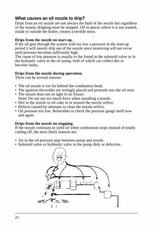
What causes an oil nozzle to drip?Drips from an oil nozzle are not always the fault of the nozzle but regardlessof the reason, dripping must be stopped. Oil in places where it is not wanted,inside or outside the boiler, creates a terrible mess.
Drips from thc nozzle on start-up.If the oil gets through the system with too low a pressure in the start-upperiod it will merely drip out of the nozzle since atomizing will not occuruntil pressure becomes sufficienly high.The cause of low pressure is usually to the found in the solenoid valve or inthe hydraulic valve in the oil pump, both of which can collect dirt orbecome faulty.
Drips from the nozzle during operation.There can he several reasons:
• The oil nozzle is too far behind the combustion head.• The ignition electrodes are wrongly placed and protrude into the oil mist.• The nozzle does not sit tight in its fixture.
Note! Do not use too much force when installing a nozzle.• Dirt in the nozzle or oil coke in or around the nozzle orifice.• Defects caused by attempts to clean the nozzle orifice.• Oil pressure too low. Remember to check the pressure gauge itself now
and again.
Drips from the nozzle on stopping.If the nozzle continues to yield oil when combustion stops instead of totallycutting off, the most likely reasons are:
• Air in the oil pressure pipe between pump and nozzle.• Solenoid valve or hydraulic valve in the pump dirty or defective.

23
What makes the flame lopsided?A lopsided flame is a guarantee for bad combustion and must be put rightimmediately.
The flame can become lopsided from:
• Wear in the oil nozzle.• Dirt inside the nozzle – in the cone slots for example.• Attempts to clean the nozzle with sharp instruments or by brute force.• Oil coke on the tip of the nozzle.• Off-centre installation of the nozzle in the burner tube. It must be precisely
central.• Unsymmetrical air supply because of a faulty combustion head. A dirty or
clogged combustion head will cause an unbalanced air supply.
24
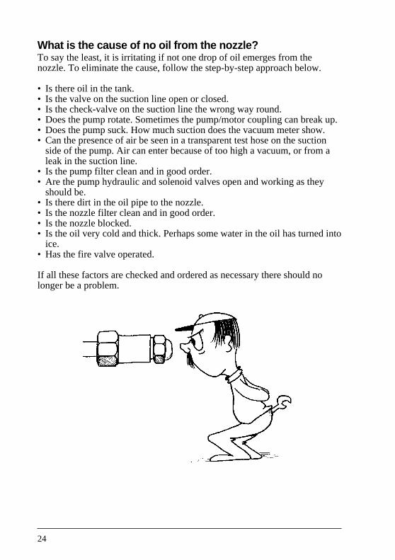
What is the cause of no oil from the nozzle?To say the least, it is irritating if not one drop of oil emerges from thenozzle. To eliminate the cause, follow the step-by-step approach below.
• Is there oil in the tank.• Is the valve on the suction line open or closed.• Is the check-valve on the suction line the wrong way round.• Does the pump rotate. Sometimes the pump/motor coupling can break up.• Does the pump suck. How much suction does the vacuum meter show.• Can the presence of air be seen in a transparent test hose on the suction
side of the pump. Air can enter because of too high a vacuum, or from aleak in the suction line.
• Is the pump filter clean and in good order.• Are the pump hydraulic and solenoid valves open and working as they
should be.• Is there dirt in the oil pipe to the nozzle.• Is the nozzle filter clean and in good order.• Is the nozzle blocked.• Is the oil very cold and thick. Perhaps some water in the oil has turned into
ice.• Has the fire valve operated.
If all these factors are checked and ordered as necessary there should nolonger be a problem.
25
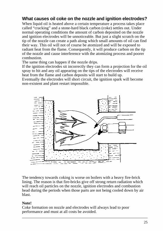
What causes oil coke on the nozzle and ignition electrodes?When liquid oil is heated above a certain temperature a process takes placecalled “cracking” and a stone-hard black carbon (coke) settles out. Undernormal operating conditions the amount of carbon deposited on the nozzleand ignition electrodes will be unnoticeable. But just a slight scratch on thetip of the nozzle can create a path along which small amounts of oil can findtheir way. This oil will not of course be atomized and will be exposed toradiant heat from the flame. Consequently, it will produce carbon on the tipof the nozzle and cause interference with the atomizing process and poorercombustion.The same thing can happen if the nozzle drips.If the ignition electrodes sit incorrectly they can form a projection for the oilspray to hit and any oil appearing on the tips of the electrodes will receiveheat from the flame and carbon deposits will start to build up.Eventually the electrodes will short circuit, the ignition spark will becomenon-existent and plant restart impossible.
The tendency towards coking is worse on boilers with a heavy fire-bricklining. The reason is that fire-bricks give off strong return radiation whichwill reach oil particles on the nozzle, ignition electrodes and combustionhead during the periods when those parts are not being cooled down by airblast.
Note!Coke formation on nozzle and electrodes will always lead to poorperformance and must at all costs be avoided.
26
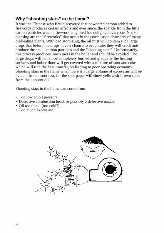
Why “shooting stars” in the flame?It was the Chinese who first discovered that powdered carbon added tofirewords produces certain effects and ever since, the sparkle from the littlecarbon particles when a firework is ignited has delighted everyone. Not sopleasing are the “fireworks” that occur in the combustion chambers of manyoil-heating plants. With bad atomizing, the oil mist will contain such largedrops that before the drops have a chance to evaporate, they will crack andproduce the small carbon particles and the “shooting stars”. Unfortunately,this process produces much mess in the boiler and should be avoided. Thelarge drops will not all be completely burned and gradually the heatingsurfaces and boiler floor will get covered with a mixture of soot and cokewhich will ruin the heat transfer, so leading to poor operating economy.Shooting stars in the flame when there is a large volume of excess air will beevident from a soot test, for the soot paper will show yellowish-brown spotsfrom the unburnt oil.
Shooting stars in the flame can come from:
• Too low an oil pressure.• Defective combustion head, or possibly a defective nozzle.• Oil too thick, (too cold?).• Too much excess air.

27
What produces a greasy malodorous deposit in theboiler and how can it be removed?When an oil-heating plant can be detected from a distance by its smell, themost frequent cause is the interior of the boiler being covered with a blackshiny greasy substance which is not so easy to remove.This substance is usually created when the oil burner has too large anexcess of air. Some of the ignited oil becomes cooled down so violentlythat it is extinguished before being completely burned out.Since the lightest contents in the oil are the first to be burned, what is leftif the oil is not completely consumed are the tars. Tarry deposits areavoidable so long as oil combustion does not involve too much excess air.Also, as high a CO2 percentage must always be maintained – withoutforgetting the soot count.Tarry deposits can be burnt off, but if they are very thick the advice of achimney cleaning specialist should be sought. Consulting the local firebrigade is also a good idea.Basically, burning-off is a matter of reducing the air supply and increasingboiler temperature by using the boiler thermostat.
Tarry deposits most often occur because:
• Oil combustion is accompanied by too much superfluous air.
• Too low an oil pressure, or a defective nozzle, produce oil drops which aretoo large.
28
Why does soot form in the flame?The theoretical reason for the formation of soot in a flame is very compli-cated, but, in general, oil vapour can form soot if there is a deficiency of airfor combustion.Every one of the millions of oil droplets must have the right amount of airon combustion – neither an excess nor a deficiency.
This means:
• Effective atomizing.• Effective mixing of oil and air in the correct proportions.
Soot-free, or virtually soot-free, combustion can be obtained by:
• Correct use of a high quality oil nozzle.• Correct combination of nozzle and combustion head.• Correct oil pressure.• Ensuring the required air supply to the boiler room.• Good cleaning and maintenance of the fan housing, burner tube, impeller,
combustion head and nozzle. In other words, all these parts must be free ofdamage and dirt.
• Insulating the chimney to ensure stable draught.• Oil must not be cooled too much.
Since layers of soot have very unfortunate effects both on operatingeconomy and the environment, every time adjustments are made to the planta soot count ought to be taken.
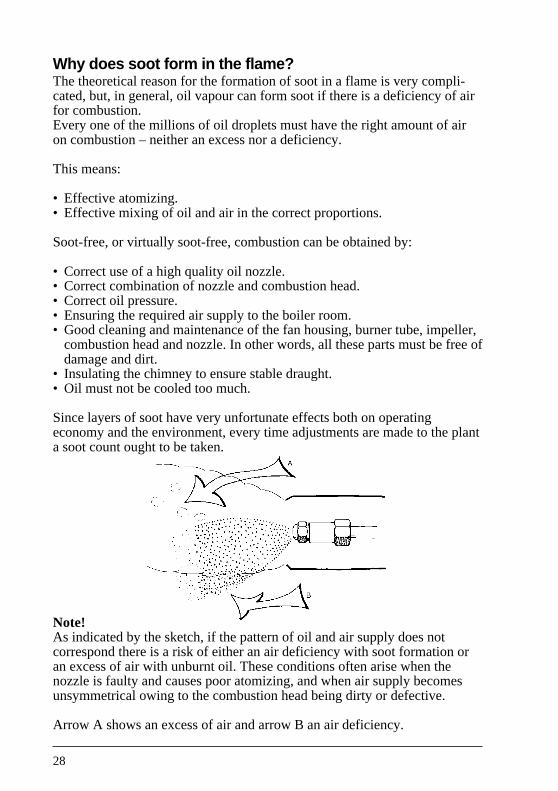
Note!As indicated by the sketch, if the pattern of oil and air supply does notcorrespond there is a risk of either an air deficiency with soot formation oran excess of air with unburnt oil. These conditions often arise when thenozzle is faulty and causes poor atomizing, and when air supply becomesunsymmetrical owing to the combustion head being dirty or defective.
Arrow A shows an excess of air and arrow B an air deficiency.

29
What causes the oil to ignite with a bang?One experience of the mess that mistimed ignition can make is enough tomake most people try and avoid its repetition.
When oil ignites with an explosion there can be several reasons:
• The ignition spark can jump from an electrode to the combustion headinstead of from one electrode to the other – as a rule, because theelectrodes are incorrectly located.
• After many attempts to restart the plant manually, a cloud of oil vapourmay have collected inside the boiler, when ignition does take place this oilcloud will ignite with a bang. If ignition does not occur after one or twoattempts, it is wise to find out why, rather than attempt further re-starts.
• The nozzle may have been installed so far forward that the air velocityaround it is high enough to blow the air/oil mixture away from the nozzleand ignition spark. Then, the mixture in the chamber in front of the nozzlebecomes so charged that it enlarges and reaches the spark so that anuncontrollably large amount of oil ignites in one big bang.
• Too low an oil pressure and atomizing lopsided because of a defectivenozzle.
• Oil can collect in the burner tube because of drips from the nozzle orleakage between nozzle and nozzle fixture. At some time or other this oilwill become heated sufficiently for it to start vapourizing. Then, if anuncontrolled amount of this vapour enters the combustion chamber, therewill be a minor explosion.

30
What can be wrong if there is no flame?After carefully doing everything to make the plant run it is very frustratingwhen no flame appears.
There can be many reasons, among them:
• No oil in the tank.• Leakage in the suction line.• The valve in the suction line is closed or perhaps the line has been trodden
flat.• The oil pump will not suck.• The oil pump does not rotate because the coupling is worn out.• The solenoid valve on the oil pressure line will not open.• Dirt in the oil tank is being sucked up to block the pump and nozzle.• Oil nozzle blocked because dirt has entered when fitting it.• No spark because of a fault in the transformer or because of faulty leads.• No spark due to short-circuited electrodes – or oil coke or soot deposits on
the porcelain insulators.• Pump rotates in the wrong direction.• If valve on the suction line is the wrong way round.• The oil is too thick (too cold?).• Pressure pipe to the oil nozzle blocked up.• Suction and return lines reversed.• The oil supply to the pump may have been set up for a two-pipe system
where a one-pipe system exists, (or vice versa).• Oil pump hydraulic valve defective.• Oil pump pressure too low.• Air in the suction line because of too high a vacuum (5 - 6 m wg).

31
What causes leakage between oil nozzle and nozzlefixture?Dirt between the joint surfaces of nozzle and fixture can cause leakage,but the worst danger is from the use of excessive force when screwing thenozzle into its fixture. Just as with all other spanner work, too much forcedoes more harm than good and with nozzles and fixtures it will result indamage to the very carefully machined joint surfaces.Therefore, excessive force must never be applied, the use of packingtwine, joint paste or the like is also not permissible.The two most important rules for making a good seal between the nozzleand its fixture are: careful handling to avoid damage to the joint surfacesand making sure that the surfaces are clean before assembly.
32
Can the nozzle be the reason for the flue-gas temperaturebeing too high?High flue-gas temperature, for example 300-350°C, is a sign that the plant isnot running economically and it should be looked into. There are manyreasons for excessive flue-gas temperature but it is important to know whichof them can be attributed to the oil nozzle:
• Oil combustion is accompanied by too much excess air, thus CO2
percentage is too low.• Soot deposits on the boiler heating surfaces prevent heat transfer to the
water in the boiler.• Too high an oil pressure. Remember, a 0.75 USgal/h nozzle will yield
1.1 USgal of oil if the pressure is for some reason increased from 7 bar to15 bar.
• Too large a nozzle has been chosen in relation to boiler capacity. Seesection “How is the correct oil nozzle chosen?”
• The boiler baffle plate which is used to improve the heat transfer in theboiler may have been removed or burnt away.
• Fire-bricks laid incorrectly or collapsed.
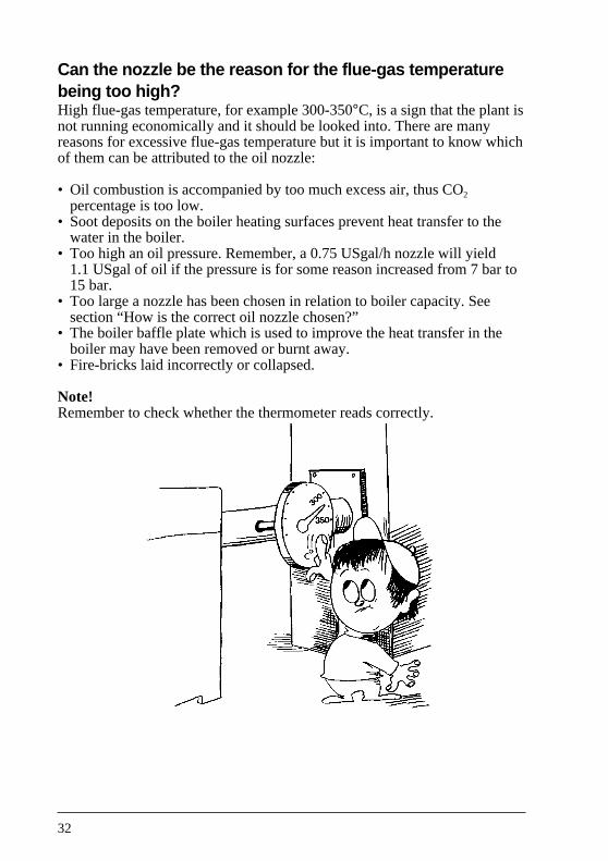
Note!Remember to check whether the thermometer reads correctly.
33
Can the nozzle cause too low a flue-gas temperature?When the flue-gas temperature is too low, for example 170-180°C, it isusually a sign of good operating economy. However, since there is a dangerthat water vapour in the gas (1 litre water vapour per kg oil) will condenseand cause damage inside the chimney and draught pipe, te reason for the lowtemperature ought to be established. The following causes should beinvestigated:
• Too small an oil nozzle has been chosen in relation to boiler capacity. Seesection “How is the correct oil nozzle chosen?”
• Too low an oil pressure. Although this will most often give rise to poorcombustion with soot formation.
• Perhaps the boiber baffle plates are too effective for the plant. This canreveal that the relation between nozzle size and boiler capacity isincorrect.
• Cold air entry into the flue pipe cools the gas down so that its temperatureappears to be low. This condition can be checked by taking CO2%measurements in the pipe. If the CO2% is low, 4-5% for example, whilethat measured in the combustion chamber is up on 10-12%, it is a suresign of air penetration through the boiler casing or through the jointbetween boiler casing and flue pipe.
Note!A lower flue-gas temperature to gain better operating economy is moredefensible on a plant with a well-lined chimney than on one with a poorchimney lining (and, without doubt, internal chimney dimensions which arealtogether too large).
34
What makes the flame too long?If the flame becomes too long it may lick the boiler heating surfaces andcause sooty combustion. Under certain circumstances, cracked oil can cakearound the combustion chamber walls.
The flame can become too long because:
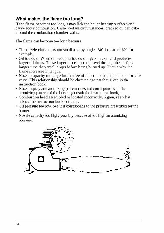
• The nozzle chosen has too small a spray angle –30° instead of 60° forexample.
• Oil too cold. When oil becomes too cold it gets thicker and produceslarger oil drops. These larger drops need to travel through the air for alonger time than small drops before being burned up. That is why theflame increases in length.
• Nozzle capacity too large for the size of the combustion chamber – or viceversa. This relationship should be checked against that given in theinstruction book.
• Nozzle spray and atomizing pattern does not correspond with theatomizing pattern of the burner (consult the instruction book).
• Combustion head assembled or located incorrectly. Again, see whatadvice the instruction book contains.
• Oil pressure too low. See if it corresponds to the pressure prescribed for theburner.
• Nozzle capacity too high, possibly because of too high an atomizingpressure.
35
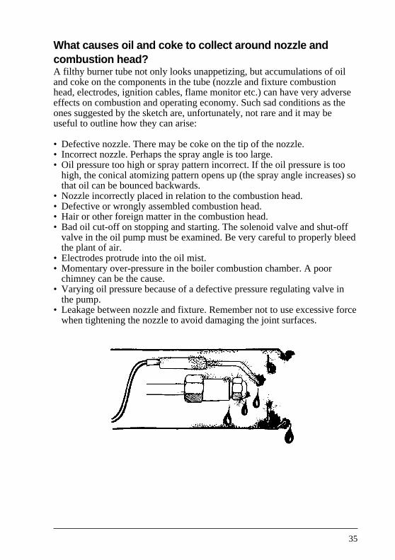
What causes oil and coke to collect around nozzle andcombustion head?A filthy burner tube not only looks unappetizing, but accumulations of oiland coke on the components in the tube (nozzle and fixture combustionhead, electrodes, ignition cables, flame monitor etc.) can have very adverseeffects on combustion and operating economy. Such sad conditions as theones suggested by the sketch are, unfortunately, not rare and it may beuseful to outline how they can arise:
• Defective nozzle. There may be coke on the tip of the nozzle.• Incorrect nozzle. Perhaps the spray angle is too large.• Oil pressure too high or spray pattern incorrect. If the oil pressure is too
high, the conical atomizing pattern opens up (the spray angle increases) sothat oil can be bounced backwards.
• Nozzle incorrectly placed in relation to the combustion head.• Defective or wrongly assembled combustion head.• Hair or other foreign matter in the combustion head.• Bad oil cut-off on stopping and starting. The solenoid valve and shut-off
valve in the oil pump must be examined. Be very careful to properly bleedthe plant of air.
• Electrodes protrude into the oil mist.• Momentary over-pressure in the boiler combustion chamber. A poor
chimney can be the cause.• Varying oil pressure because of a defective pressure regulating valve in
the pump.• Leakage between nozzle and fixture. Remember not to use excessive force
when tightening the nozzle to avoid damaging the joint surfaces.
36
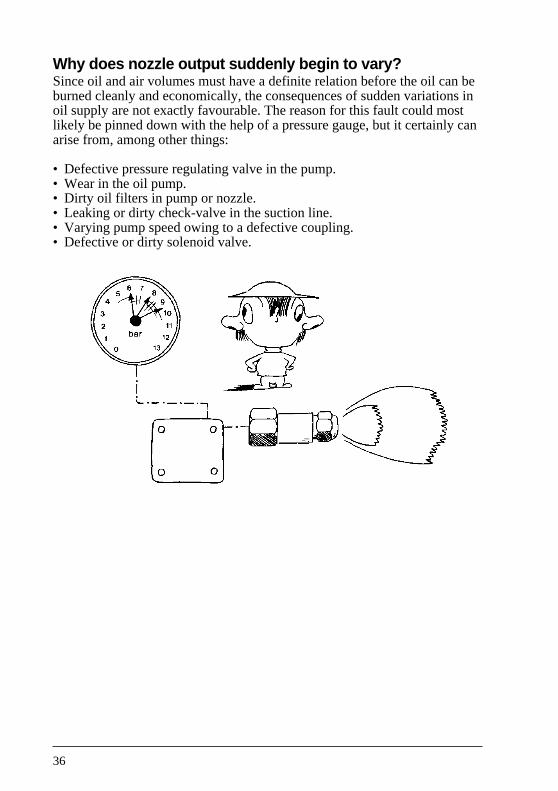
Why does nozzle output suddenly begin to vary?Since oil and air volumes must have a definite relation before the oil can beburned cleanly and economically, the consequences of sudden variations inoil supply are not exactly favourable. The reason for this fault could mostlikely be pinned down with the help of a pressure gauge, but it certainly canarise from, among other things:
• Defective pressure regulating valve in the pump.• Wear in the oil pump.• Dirty oil filters in pump or nozzle.• Leaking or dirty check-valve in the suction line.• Varying pump speed owing to a defective coupling.• Defective or dirty solenoid valve.

37
What to do with old, worn out nozzles?Avoiding waste and re-use are topical subjects at the moment and thereare many things which can be used again and again. Not so the oil nozzle.It is a good friend when new, but an old or worn nozzle should not be usedas a spare.For the sake of economy, and safety, old nozzles must be thrown away.
38
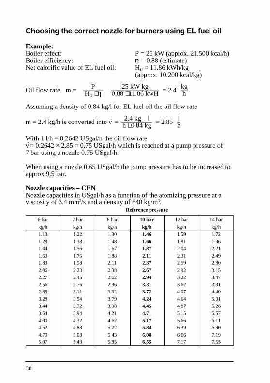
Choosing the correct nozzle for burners using EL fuel oil
Example:Boiler effect: P = 25 kW (approx. 21.500 kcal/h)Boiler efficiency: η = 0.88 (estimate)Net calorific value of EL fuel oil: HU = 11.86 kWh/kg
(approx. 10.200 kcal/kg)
P 25 kW kg kgOil flow rate m = –––––– –––––––––––––– = 2.4 ––HU ⋅ η 0.88 ⋅ 11.86 kwH h
Assuming a density of 0.84 kg/l for EL fuel oil the oil flow rate
2.4 kg l lm = 2.4 kg/h is converted into v· = ––––––––– = 2.85 –h ⋅ 0.84 kg h
With 1 l/h = 0.2642 USgal/h the oil flow ratev· = 0.2642 × 2.85 = 0.75 USgal/h which is reached at a pump pressure of7 bar using a nozzle 0.75 USgal/h.
When using a nozzle 0.65 USgal/h the pump pressure has to be increased toapprox 9.5 bar.
Nozzle capacities – CENNozzle capacities in USgal/h as a function of the atomizing pressure at aviscosity of 3.4 mm2/s and a density of 840 kg/m3.
Reference pressure
6 bar 7 bar 8 bar 10 bar 12 bar 14 bar
kg/h kg/h kg/h kg/h kg/h kg/h
1.13 1.22 1.30 1.46 1.59 1.72
1.28 1.38 1.48 1.66 1.81 1.96
1.44 1.56 1.67 1.87 2.04 2.21
1.63 1.76 1.88 2.11 2.31 2.49
1.83 1.98 2.11 2.37 2.59 2.80
2.06 2.23 2.38 2.67 2.92 3.15
2.27 2.45 2.62 2.94 3.22 3.47
2.56 2.76 2.96 3.31 3.62 3.91
2.88 3.11 3.32 3.72 4.07 4.40
3.28 3.54 3.79 4.24 4.64 5.01
3.44 3.72 3.98 4.45 4.87 5.26
3.64 3.94 4.21 4.71 5.15 5.574.00 4.32 4.62 5.17 5.66 6.11
4.52 4.88 5.22 5.84 6.39 6.904.70 5.08 5.43 6.08 6.66 7.19
5.07 5.48 5.85 6.55 7.17 7.55
39
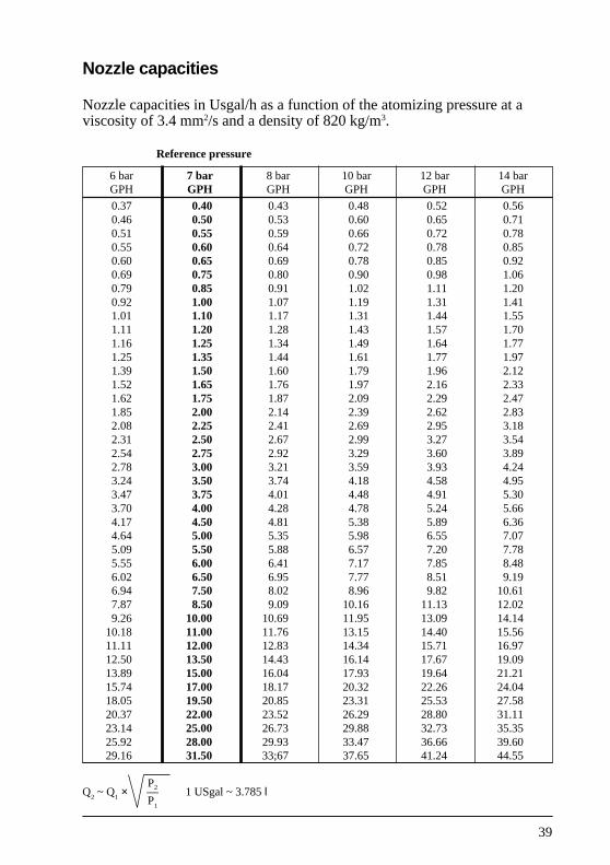
Nozzle capacities
Nozzle capacities in Usgal/h as a function of the atomizing pressure at aviscosity of 3.4 mm2/s and a density of 820 kg/m3.
Reference pressure
6 bar 7 bar 8 bar 10 bar 12 bar 14 barGPH GPH GPH GPH GPH GPH
0.37 0.40 0.43 0.48 0.52 0.560.46 0.50 0.53 0.60 0.65 0.710.51 0.55 0.59 0.66 0.72 0.780.55 0.60 0.64 0.72 0.78 0.850.60 0.65 0.69 0.78 0.85 0.920.69 0.75 0.80 0.90 0.98 1.060.79 0.85 0.91 1.02 1.11 1.200.92 1.00 1.07 1.19 1.31 1.411.01 1.10 1.17 1.31 1.44 1.551.11 1.20 1.28 1.43 1.57 1.701.16 1.25 1.34 1.49 1.64 1.771.25 1.35 1.44 1.61 1.77 1.971.39 1.50 1.60 1.79 1.96 2.121.52 1.65 1.76 1.97 2.16 2.331.62 1.75 1.87 2.09 2.29 2.471.85 2.00 2.14 2.39 2.62 2.832.08 2.25 2.41 2.69 2.95 3.182.31 2.50 2.67 2.99 3.27 3.542.54 2.75 2.92 3.29 3.60 3.892.78 3.00 3.21 3.59 3.93 4.243.24 3.50 3.74 4.18 4.58 4.953.47 3.75 4.01 4.48 4.91 5.303.70 4.00 4.28 4.78 5.24 5.664.17 4.50 4.81 5.38 5.89 6.364.64 5.00 5.35 5.98 6.55 7.075.09 5.50 5.88 6.57 7.20 7.785.55 6.00 6.41 7.17 7.85 8.486.02 6.50 6.95 7.77 8.51 9.196.94 7.50 8.02 8.96 9.82 10.617.87 8.50 9.09 10.16 11.13 12.029.26 10.00 10.69 11.95 13.09 14.14
10.18 11.00 11.76 13.15 14.40 15.5611.11 12.00 12.83 14.34 15.71 16.9712.50 13.50 14.43 16.14 17.67 19.0913.89 15.00 16.04 17.93 19.64 21.2115.74 17.00 18.17 20.32 22.26 24.0418.05 19.50 20.85 23.31 25.53 27.5820.37 22.00 23.52 26.29 28.80 31.1123.14 25.00 26.73 29.88 32.73 35.3525.92 28.00 29.93 33.47 36.66 39.6029.16 31.50 33;67 37.65 41.24 44.55
P2Q2 ~ Q
1 × –– 1 USgal ~ 3.785 l
P1

40


Danfoss can accept no responsibility for possible errors in catalogues, brochures and other printed material. Danfoss reserves the right to alter its products without notice. This also applies toproducts already on order provided that such alterations can be made without subsequential changes being necessary in specifications already agreed.All trademarks in this material are property of the respective companies. Danfoss and the Danfoss logotype are trademarks of Danfoss A/S. All rights reserved.
520F0019 – DKBG.PG.060.A8.02 Produced by Danfoss G1 advertising agency 00.06 FO-Bi.LT