Facts worth knowing about hydraulics - Beth and Evans
40
HZ.00.A2.02 Facts worth knowing about hydraulics ■ ■ Hydra ■ ■ Hydraulics ydraulics ■ ■ Hydrau lique ■ ■ Hydraulik ■ ■ Hydr ik ■ ■ Hydraulics ■ ■ Hydraulique raulique ■ ■ Hydraulik ■ ■ Hydraulics ■ ■ H raulik ■ ■ Hydraulics ■ ■ Hydraulique ■ ■ Hyd que ■ ■ Hydraulik ■ ■ Hydraulics ■ ■ Hydrauli raulique ■ ■ Hydraulik ■ ■ Hydraulics ■ ■ Hyd ■ ■ Hydraulique ■ ■ Hydraulik ■ ■ Hydraulics draulics ■ ■ Hydraulique ■ ■ Hydraulik ■ ■ Hy k ■ ■ Hydraulics ■ ■ Hydraulique ■ ■ Hydrauli draulik ■ ■ Hydraulics ■ ■ Hydraulique ■ ■ H e ■ ■ Hydraulik ■ ■ Hydraulics ■ ■ Hyd ique ■ ■ Hydraulik ■ ■ Hydraul lik ■ ■ Hydraulics ■ ■ Hyd ique ■ ■ Hydrauli lics ■ ■ Hyd Hydr
Transcript of Facts worth knowing about hydraulics - Beth and Evans
HZ.00.A2.02
Facts worthknowing abouthydraulics
■■■■ Hydra
■■■■ Hydraulics
ydraulics■■■■ Hydrau
lique■■■■ Hydraulik
■■■■ Hydr
ik■■■■ Hydraulics
■■■■ Hydraulique
raulique■■■■ Hydraulik
■■■■ Hydraulics■■■■ H
raulik■■■■ Hydraulics
■■■■ Hydraulique■■■■ Hyd
que■■■■ Hydraulik
■■■■ Hydraulics■■■■ Hydrauli
raulique■■■■ Hydraulik
■■■■ Hydraulics■■■■ Hyd
■■■■ Hydraulique■■■■ Hydraulik
■■■■ Hydraulics
draulics■■■■ Hydraulique
■■■■ Hydraulik■■■■ Hy
k■■■■ Hydraulics
■■■■ Hydraulique■■■■ Hydrauli
draulik■■■■ Hydraulics
■■■■ Hydraulique■■■■ H
e■■■■ Hydraulik
■■■■ Hydraulics■■■■ Hyd
ique■■■■ Hydraulik
■■■■ Hydraul
lik■■■■ Hydraulics
■■■■ Hyd
ique■■■■ Hydrauli
lics■■■■ Hyd
Hydr
2 HZ.00.A2.02
Contents
Page
1. Introduction............................................................................................................. 3
2. Sizing..................................................................................................................... 4
3. Selection of components.......................................................................................... 9
4. Selection of oil type.....................................................................................................13
5. Checking the oil...................................................................................................... 18
6. Installation of system.............................................................................................. 18
7. Starting up and running in of plant ........................................................................ 21
8. Maintenance.......................................................................................................... 23
9. Fault location............................................................................................................ 24
10. Repair and testing ................................................................................................. 34
11. Symbols and tables ............................................................................................... 35
12. ISO/CETOP-symbols ............................................................................................ 36
13. Overview of Danfoss SERVICE SHOPS............................................................... 40
3
Introduction
HZ.00.A2.02
Like so many other technical fields, hydraulicsis both old and new at the same time.
Take waterwheels for example, people havebeen using them since before history wasrecorded. On the other hand, the use of liquidunder pressure to transfer force and also tocontrol complicated movements is relativelynew and has undergone its most rapid devel-opment within the last 40-50 years, not leastbecause of the work that has been done inaeronautics.
Hydraulics and pneumatics are universal forthe entire engineering industry and areamongst the three most important media forthe transference and control of force. The twoother media are mechanical transference forexample via clutch pedals and gears) and electrical (for example via a generator)."Flowing energy" is transferred and controlledthrough a medium under pressure - either air(pneumatic) or liquid (hydraulic).
This form of energy has many exceptionaladvantages and is therefore often the mostsuitable form of energy transference on land,sea or in the air.
A contained liquid is one of the most versatilemeans of controlling and transferring force. Ittakes the precise form of the walls that containit and withstands its pressure. It can be divi-ded into several streams which, depending ontheir size, can perform work before beingallowed to merge into one stream again toperform still more work. It can be made towork fast in one part of a system and slowly inanother.
No other medium combines the same degreeof reliability, accuracy and flexibility while retai-ning the capability of transferring maximumforce with minimum volume and weight. Thequality control with this medium can be com-pared with the accuracy of an electronicmicro-processor.
However, to achieve maximum utilization withhighest efficiency and least possible operatio-nal stops, it is very important that a hydraulicsystem be designed, manufactured, startedand maintained absolutely correctly. The spe-cial factors vital to the user (purchaser) mustalso be understood if operation in the field isnot to be plagued by break downs and otherdisturbances.
Nearly all factory systems use "flowingenergy" in production. More than half of allmanufactured products are based on this formof energy, and it is therefore of interest to allmanufacturers, exporters, purchasers, distributors, and repairers of productionsystems and machines, including agriculturalmachines and machine tools, the villagesmithy and the automobile industry, shippingand aviation.
Clearly, the knowledge and experience ofmany designers, producers, repairers andowners (users) is being outstripped by the dra-matic development and rapid spread ofhydraulics.
The purpose of this article is therefore not totry to provide patent solutions to all hydraulicproblems, but to help create an understandingof why problems arise and what steps can betaken to avoid them.

Sizing
4 HZ.00.A2.02
Reliable sizing provides the most optimal selecti-on of components.
It is obvious that if undersize components areused, they will not operate under overload. Theywill be sensitive and become a frequent sourceof problems and complaints. More important still,in comparison with a correctly sized componentan oversize component will probably operateproblem-free and "effortlessly" for a very longtime, but its original price will be too high.
If not able to carry out accurate calculations toobtain optimum conditions, the guidelines beloware worth following.The first thing to establish is the max. operatingpressure required for the system since this is thedecisive factor in pump selection and, in turn,important as far as the size (output) of the prime
mover and the system price are concerned. Thehigher the operation pressure, the higher the pri-ce of many of the components.
When the economic considerations have beenmade, particular types and sizes of operatingcylinders, motors, and steering units to be usedin the system can be considered.
The pump size is found by adding the necessaryamounts of oil (expressed in gallon (litres) perminute) that can be in use at the same time.Consequently, the total is the amount the pumpmust be able to supply at the maximum intermit-tent operating pressure (= pressure relief valve setting pressure).
Size of pump The power applied to the pump must be found asa function of the pressure in psi (bar), revolutionsper minute and flow in gal (litres) per minute,expressed in Hp (kW). The result can be used tofind the size of motor that will safely yield thenecessary output. See the following example.
Hydraulic output N = pressure x flow, i.e. N = p x Q
Example:p × Q
N = [ Hp ]400
p = 2175 psi2175 × 11.9
Q = 11.9 gal/min N = = 64.71 Hp400
When calculating the necessary pump output(Pnec), account must be taken of the total pumpefficiency, (ηtot.) as stated in the catalogue.
Example:p × Q 2175 × 11.9
Pan = = = 71.9 Hp400 × η t 400 × 0,9
Q × 1000V = cm3/min-1
n × ηvol
Sizes of pipes and hoses The size depends on:
- max. system pressure- max. oil flow- length of pipe system- environmental conditions
Pressure drop must be as small as possible. Thegreater the resistance in the system, the greaterthe operational loss. It is important to avoid thosefactors which cause pressure drop, for examplethe use of angled screwed connec-tions. Where possible, these should be replacedby elbows. If long lengths of pipe or high flow velocity are involved, then an increase in diameter up to the next size should be considered.
Remember that the dimensions stated for thehydraulic pipes are the external diameters andwall thicknesses. The internal diameters areequal to the external diameters minus 2 x thewall thickness.
Remember that when the internal diameter isdoubled, the flow area of the pipe is quadrupled.
Now the oil capacity supplied per minute by thepump is known, along with the amount of oil theindividual components must have. The next stage is the dimensioning of pipes and hoses.This is also very important as otherwise, genera-ted cavitation (noise), heat generation, pressuredrop and, in some cases, bursting can occur.
There are many people who are frightened ofthis dimensioning as they associate it, incorrectly,with difficult mathematical calculations. In actualfact, if the nomogram adjacent is followed whencalculating pipe dimensions, it is incredibly simple.
In order to use the nomogram, the first thing is toknow the oil flow in gallons (liters) per minute.After this it has to be known whether the pipesand hoses in question are to be used as suctionlines, pressure lines or return lines. This isbecause there are some recommended velociti-es of oil flow available for these categories. The-se values are as follows:
- Suction line 1.6 - 4.9 ft/s- Pressure line 9.8 - 32.8 ft/s- Return line 6.6 - 16.4 ft/s
Sizing
5HZ.00.A2.02
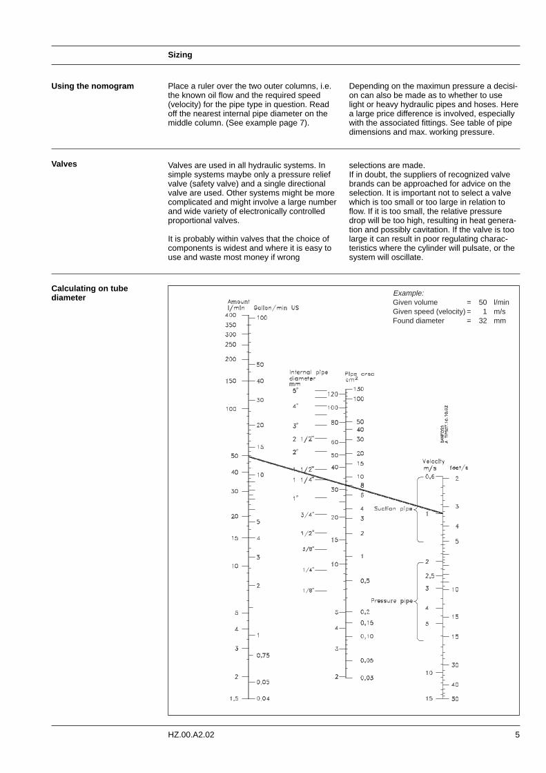
Place a ruler over the two outer columns, i.e.the known oil flow and the required speed (velocity) for the pipe type in question. Readoff the nearest internal pipe diameter on themiddle column. (See example page 7).
Depending on the maximun pressure a decisi-on can also be made as to whether to use light or heavy hydraulic pipes and hoses. Herea large price difference is involved, especiallywith the associated fittings. See table of pipedimensions and max. working pressure.
Valves are used in all hydraulic systems. Insimple systems maybe only a pressure reliefvalve (safety valve) and a single directionalvalve are used. Other systems might be morecomplicated and might involve a large numberand wide variety of electronically controlledproportional valves.
It is probably within valves that the choice ofcomponents is widest and where it is easy touse and waste most money if wrong
selections are made. If in doubt, the suppliers of recognized valvebrands can be approached for advice on theselection. It is important not to select a valvewhich is too small or too large in relation toflow. If it is too small, the relative pressuredrop will be too high, resulting in heat genera-tion and possibly cavitation. If the valve is toolarge it can result in poor regulating charac-teristics where the cylinder will pulsate, or thesystem will oscillate.
Using the nomogram
Valves
Calculating on tube diameter Example:
Given volume = 50 l/minGiven speed (velocity) = 1 m/sFound diameter = 32 mm
Sizing
6 HZ.00.A2.02
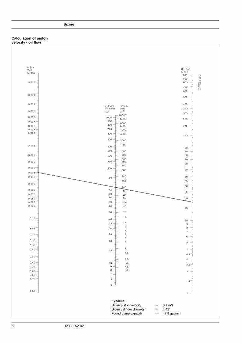
Calculation of pistonvelocity - oil flow
Example: Given piston velocity = 0,1 m/sGiven cylinder diameter = 4.41” Found pump capacity = 47.8 gal/min
Sizing
7HZ.00.A2.02
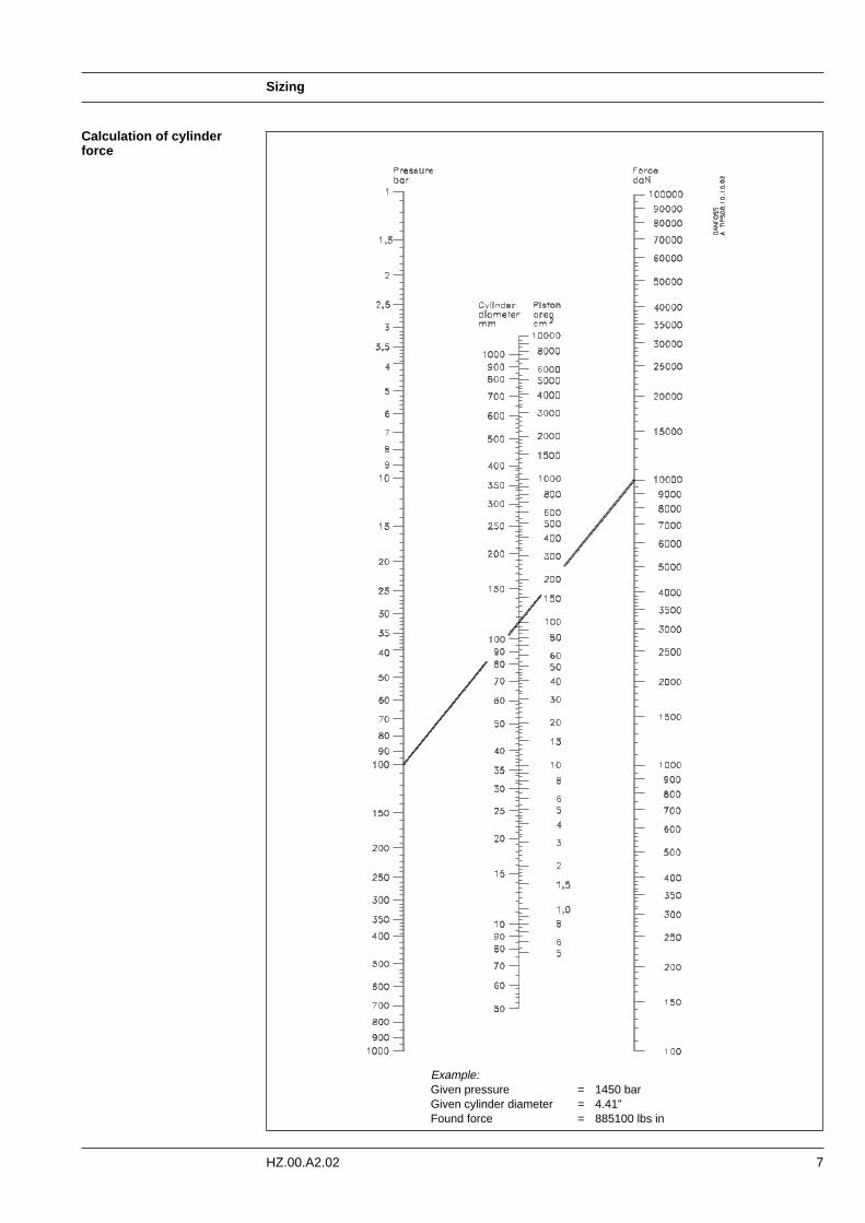
Calculation of cylinder force
Example: Given pressure = 1450 barGiven cylinder diameter = 4.41” Found force = 885100 lbs in
Sizing
8 HZ.00.A2.02
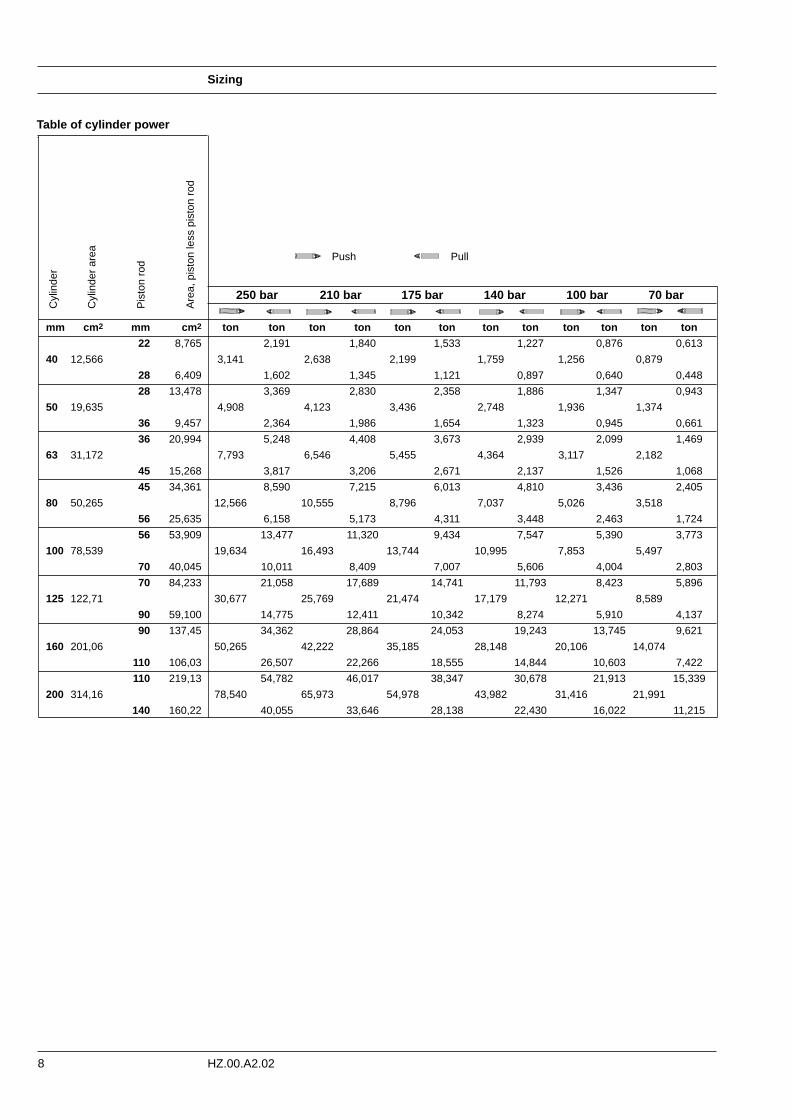
Table of cylinder power
250 bar 210 bar 175 bar 140 bar 100 bar 70 bar
mm cm 2 mm cm 2 ton ton ton ton ton ton ton ton ton ton ton ton
22 8,765 2,191 1,840 1,533 1,227 0,876 0,613
40 12,566 3,141 2,638 2,199 1,759 1,256 0,879
28 6,409 1,602 1,345 1,121 0,897 0,640 0,448
28 13,478 3,369 2,830 2,358 1,886 1,347 0,943
50 19,635 4,908 4,123 3,436 2,748 1,936 1,374
36 9,457 2,364 1,986 1,654 1,323 0,945 0,661
36 20,994 5,248 4,408 3,673 2,939 2,099 1,469
63 31,172 7,793 6,546 5,455 4,364 3,117 2,182
45 15,268 3,817 3,206 2,671 2,137 1,526 1,068
45 34,361 8,590 7,215 6,013 4,810 3,436 2,405
80 50,265 12,566 10,555 8,796 7,037 5,026 3,518
56 25,635 6,158 5,173 4,311 3,448 2,463 1,724
56 53,909 13,477 11,320 9,434 7,547 5,390 3,773
100 78,539 19,634 16,493 13,744 10,995 7,853 5,497
70 40,045 10,011 8,409 7,007 5,606 4,004 2,803
70 84,233 21,058 17,689 14,741 11,793 8,423 5,896
125 122,71 30,677 25,769 21,474 17,179 12,271 8,589
90 59,100 14,775 12,411 10,342 8,274 5,910 4,137
90 137,45 34,362 28,864 24,053 19,243 13,745 9,621
160 201,06 50,265 42,222 35,185 28,148 20,106 14,074
110 106,03 26,507 22,266 18,555 14,844 10,603 7,422
110 219,13 54,782 46,017 38,347 30,678 21,913 15,339
200 314,16 78,540 65,973 54,978 43,982 31,416 21,991
140 160,22 40,055 33,646 28,138 22,430 16,022 11,215
Cyl
inde
r
Cyl
inde
r ar
ea
Pis
ton
rod
Are
a, p
isto
n le
ss p
isto
n ro
d
Push Pull
9
Selection of components
HZ.00.A2.02
All hydraulic systems consist in principle of thesame basic components, but just as with elec-tronics, the combinations are infinite and therange of components immense.Which components are the most important ina system?
....is it the cylinder or the motor that is going to perform the work,
....or the liquid (oil) that transfers force to the motor or cylinder,
... or the pipes and hoses that lead oil to motor and cylinder,
....or the valves that control the oil flow paths,
....or the pump that applies energy and movement to the oil,
....or the motor that drives the pump,
....or the filter that removes dirt from the oil,
....or the oil cooler that ensures a suitable oil temperature,
....or the tank that contains oil for the system..
The answer must be that specific demandsare made on all these components and sincenone of them can be allowed to fail, they mustall be equally important. Therefore extremecare must be taken in all stages of their cre-ation, selection and application.
When a hydraulic diagram is being prepared,
the designer must have quality in mind, includ-ing the quality of the drawing itself, so that any errors in interpreting the drawing are avoided.It is a good idea always to use the correctISO/CETOP-symbols.
When the diagram is subsequently used inpreparing parts lists and accurate componentspecifications, sizing problems often occur.The designer is confronted with brightly col-oured brochures and catalogues and, at first,all is confusion. The temptation is to revert torule-of-thumb methods and "add a bit for safety's sake", the result being a system whichis either over or under designed.
All reputable hydraulic component manufac-turers give real, usable values in their cata-logues, not just theoretical desired values. Thetechnical data in Danfoss catalogues alwaysrepresents average values measured from acertain number of standard components. Inaddition to these data, the catalogues containa mass of useful and explanatory informationon selection, installation and start up of com-ponents, together with a description of theirfunctions. This information must, of course, beused as intended in order to avoid overload,too high a wear rate, and consequent oil over-heating and to avoid an over-dimensionedsystem with poor regulation at too high a price.
The tank Let us look a little closer at an examplesystem, starting with:
The tank, which has many functions e.g.
- as a reservoir for the system oil - as a cooler - as a "coarse strainer", sedimentation of
impurities - as an air and water separator - as a foundation for pumps etc.
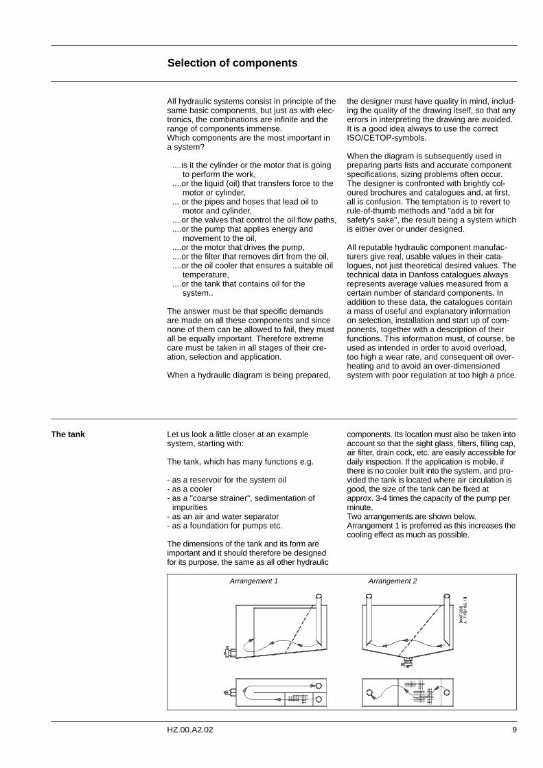
The dimensions of the tank and its form areimportant and it should therefore be designed for its purpose, the same as all other hydraulic
components. Its location must also be taken intoaccount so that the sight glass, filters, filling cap,air filter, drain cock, etc. are easily accessible fordaily inspection. If the application is mobile, ifthere is no cooler built into the system, and pro-vided the tank is located where air circulation isgood, the size of the tank can be fixed atapprox. 3-4 times the capacity of the pump perminute.Two arrangements are shown below.Arrangement 1 is preferred as this increases thecooling effect as much as possible.
Arrangement 1 Arrangement 2
Selection of components
10 HZ.00.A2.02
To increase the ability of the tank to separatedirt and water, the bottom must be slightlyinclined (deepest end opposite the inlet/outletend). An ordinary cock (without handle) is fit-ted so that impurities can easily be drained off.Increased separation of the air that is alwayspresent in the oil can be obtained by fitting aninclined coarse metal strainer (approx. 25-50mesh/ inch) by the return line.
Both suction and return pipes must be cut di-agonally. The ends of the pipes must belocated 2-4 times the pipe diameter above thebottom of the tank, partly to avoid foaming atthe return line, and partly to prevent air frombeing drawn into the suction line, especiallywhen the vehicle/vessel heels over to oneside. With regard to the annual "spring-clean",the tank must have large removable covers,either in the sides, in the top, or in the ends, inorder to give easy access for cleaning. If filtersare installed, they must be located above thetank oil level and must be easy to replacewithout significant spillage. That is to say, itmust be possible to place a drip tray under thefilter inserts.
Since tanks are made of steel plate, rust isinevitable (even below the oil level, becauseoil contains both water and oxygen) and it istherefore advisable to surface-treat the inside.If the tank is to be painted, thorough cleaningand degreasing is necessary before primerand top coats are applied. The paint usedmust, of course, be resistant to hot hydraulicoil.
If the cooling effect from the tank and otherhydraulic components is insufficient in order tokeep oil temperature down to an acceptablemaximum an oil cooler must be fitted. Mostsuppliers prescribe 194 °F (90°C) as an abso-lute max-imum partly because of lifetime ofrubber parts, partly because of alterations oftolerances and possibly bad lubrication. Todayquite often electronic devices are fitted directlyonto the hot hydraulic components. In consi-deration of the electronics, a reduction of themax. oil temper-ature to under 176 °F (80°C)must be aimed at.
Filters The degree of filtering and filter size are basedon many different criteria that generalisation isseldom possible. The most important factorsto be considered are as follows:
Operational environment: How serious would the consequences be if thesystem failed because of dirt?
Oil quantity:Would there be a few litres or several hundredlitres in the system? Is it an expensive or acheap oil?
Operational down time:What would it cost per hour/day if the systemshut down? How important is this factor?
Dirt sensitivity:How dirt-sensitive are the components? Whatdegree of filtering is recommended by thecomponent manufacturers?
Filter types:Are suction filters, pressure filters or return fil-ters to be used, or a combination of these withor without magnets? Is exclusive full-flow filte-ring involved, or will there also be by-pass fil-tering through fine filters? Which type of dirtindicators are to be used, visual, mechanicalor electrical?
Air filtration:Air must be filtered to the same degree as thefinest filter in the system, otherwise too muchdirt can enter the tank with the air. If there is alarge differential or plunger cylinders are in thesystem, the tank breathes in/pushes out largeamounts of air, therefore the size of the air fil-ter must be on the large side. Remember thatdirt particles visible to the naked eye (largerthan 40 µm) are as a rule, less dangerousthan those that cannot be seen. It is often thehard particles of 5 - 25 µm, corresponding tonormal hydraulic component tolerances, thatare the most dangerous.
Selection of components
11HZ.00.A2.02
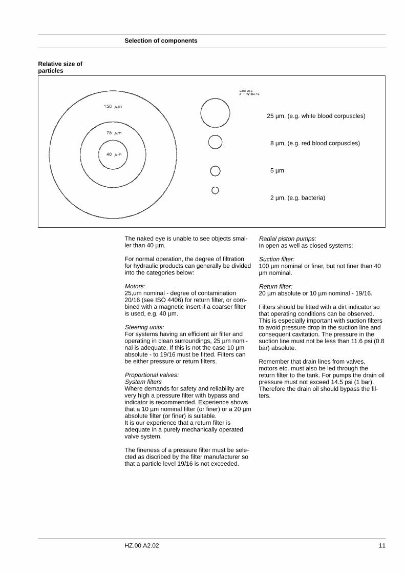
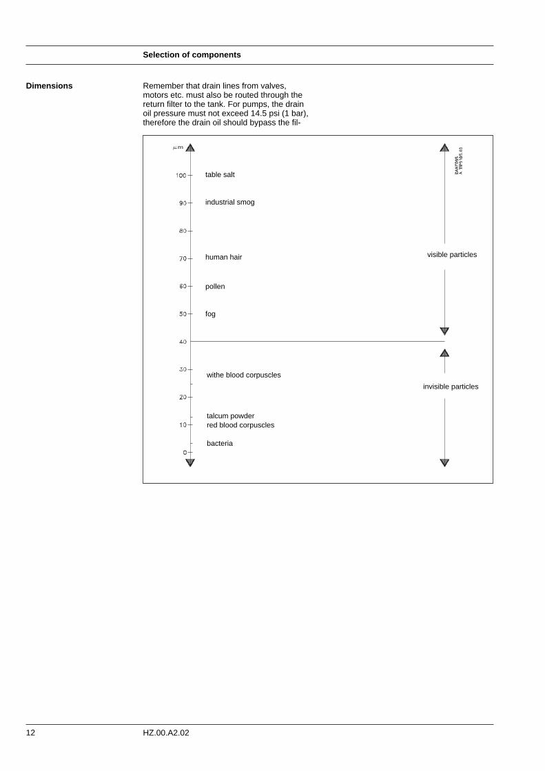
Relative size ofparticles
The naked eye is unable to see objects smal-ler than 40 µm.
For normal operation, the degree of filtrationfor hydraulic products can generally be dividedinto the categories below:
Motors:25,um nominal - degree of contamination20/16 (see ISO 4406) for return filter, or com-bined with a magnetic insert if a coarser filteris used, e.g. 40 µm.
Steering units:For systems having an efficient air filter andoperating in clean surroundings, 25 µm nomi-nal is adequate. If this is not the case 10 µmabsolute - to 19/16 must be fitted. Filters canbe either pressure or return filters.
Proportional valves:System filtersWhere demands for safety and reliability arevery high a pressure filter with bypass andindicator is recommended. Experience showsthat a 10 µm nominal filter (or finer) or a 20 µmabsolute filter (or finer) is suitable.It is our experience that a return filter isadequate in a purely mechanically operatedvalve system.
The fineness of a pressure filter must be sele-cted as discribed by the filter manufacturer sothat a particle level 19/16 is not exceeded.
Radial piston pumps: In open as well as closed systems:
Suction filter:100 µm nominal or finer, but not finer than 40µm nominal.
Return filter:20 µm absolute or 10 µm nominal - 19/16.
Filters should be fitted with a dirt indicator sothat operating conditions can be observed.This is especially important with suction filtersto avoid pressure drop in the suction line andconsequent cavitation. The pressure in thesuction line must not be less than 11.6 psi (0.8bar) absolute.
Remember that drain lines from valves,motors etc. must also be led through thereturn filter to the tank. For pumps the drain oilpressure must not exceed 14.5 psi (1 bar).Therefore the drain oil should bypass the fil-ters.
25 µm, (e.g. white blood corpuscles)
8 µm, (e.g. red blood corpuscles)
5 µm
2 µm, (e.g. bacteria)
Selection of components
12 HZ.00.A2.02
Dimensions
table salt
industrial smog
human hair
pollen
fog
withe blood corpuscles
talcum powderred blood corpuscles
bacteria
visible particles
invisible particles
Remember that drain lines from valves,motors etc. must also be routed through thereturn filter to the tank. For pumps, the drainoil pressure must not exceed 14.5 psi (1 bar),therefore the drain oil should bypass the fil-
13
Selection of oil type
HZ.00.A2.02
Oil requirements The oil in a hydraulic system must first andforemost transfer energy, but the moving partsin components must also be lubricated toreduce friction and consequent heat gener-ation. Additionally, the oil must lead dirt partic-les and friction heat away from the system andprotect against corrosion.
- good lubricating properties- good wear properties- suitable viscosity- good corrosion inhibitor- good anti-aeration properties- reliable air separation- good water separation
However, it can be an advantage to use othertypes of oils, especially in mobile systemssuch as tractors, etc. There is an advantage tobe gained here from the use of the same oilfor the diesel motor, the gearbox and thehydraulic system which often supply oil to boththe working hydraulics and the steering. Othersystems use transmission oil for the gearboxand hydraulics. In mines and off-shore installa-tions, fire retarding liquids are used.
The most common hydraulic oil is a mineralbased oil.CETOP RP75H-class is comprised of the following 4 groups:
- HH: oil without additives - HL: oil with specialadditives for improving fluid life-durability andprotecting against corrosion - HM: "HL" + addi-tives for improving wear-properties - HV: "HM" + additives for improving the viscosityindex
Oil types
- Mineral oil- Water- Oil/water-emulsions- Water/polyglycol mixture- Synthetic liquids
Types of hydraulic fluids
Fire retarding hydraulic oils are sometimesclassified as "non-inflammable hydraulic oils",but they will all burn under unfavourable conditions.
In water-based hydraulic oils it is solely thewater that makes them fire retarding. Whenthe water has evaporated, they can burn.Among synthetic fire retarding hydraulic oils,only phosphate esters are used.
It is important to select an oil type containingthe correct additives, i.e. those which matchthe problem-free operation and long operatinglife for both hydraulic components and the oilitself can be ensured by following the mainten-ance instructions.
The amount and type of these additives areseldom given by suppliers, for such precisedata are hardly of significance. The exceptionhowever, is antiwear additives because theseare important as far as avoiding seizing andprolonging the operating life of the system.
In the opinion of Danfoss, the ideal oil contains:
either : 1.0-1.4% Dialkylzincdithiophosphate(tradename Lubrizol 677A)
or : 1.0-1.6% tricresylphosphate(tradename Lindol oil)
or : 1.0-1.6% Triarylphosphate(tradename Coalite)
or : additives producing similar effects.
To improve the characteristics of a mineral oil,different kinds of additives are used. Normallythe desire is to improve the following charac-teristics:
- Lubrication with metal/metal contact at high and low speeds.
- Viscosity change must remain small in a wide temperature and pressure range. This characteristic is called the viscosity index (Vl)
- Air solubility must be low and air emission high.
- Foaming tendency must be low. - Rust protection must be high. - The toxicity of the oil and its' vapour must be
low.
Non-inflammable fluids
Additives
Selection of oil type
14 HZ.00.A2.02
Motor oil
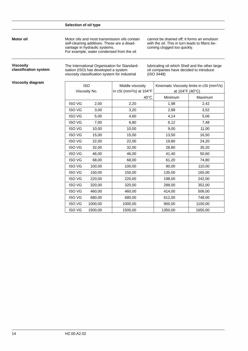
lubricating oil which Shell and the other largeoil companies have decided to introduce (ISO 3448)
The International Organisation for Standard-isation (ISO) has developed a systemviscosity classification system for industrial
Motor oils and most transmission oils containself-cleaning additives. These are a disad-vantage in hydraulic systems. For example, water condensed from the oil
cannot be drained off; it forms an emulsionwith the oil. This in turn leads to filters be-coming clogged too quickly.
Viscosityclassification system
Viscosity diagramISO Middle viscosity Kinematic Viscosity limits in cSt (mm2/s)
Viscosity No. in cSt (mm2/s) at 104°F at 104°F (40°C)
40°C Minimum Maximum
ISO VG 2,00 2,20 1,98 2,42
ISO VG 3,00 3,20 2,88 3,52
ISO VG 5,00 4,60 4,14 5,06
ISO VG 7,00 6,80 6,12 7,48
ISO VG 10,00 10,00 9,00 11,00
ISO VG 15,00 15,00 13,50 16,50
ISO VG 22,00 22,00 19,80 24,20
ISO VG 32,00 32,00 28,80 35,20
ISO VG 46,00 46,00 41,40 50,60
ISO VG 68,00 68,00 61,20 74,80
ISO VG 100,00 100,00 90,00 110,00
ISO VG 150,00 150,00 135,00 165,00
ISO VG 220,00 220,00 198,00 242,00
ISO VG 320,00 320,00 288,00 352,00
ISO VG 460,00 460,00 414,00 506,00
ISO VG 680,00 680,00 612,00 748,00
ISO VG 1000,00 1000,00 900,00 1100,00
ISO VG 1500,00 1500,00 1350,00 1650,00
15
Checking the oil
HZ.00.A2.02
Water in the oil There is evidence that more than 70% of allproblems with hydraulic systems can be traced directly to the condition of the oil.If there is water in the oil, the oil must be re-placed as this not only damages the ball androller bearings but also causes corrosion of allsteel surfaces. This especially applies to those surfaces touched by the oil, for in addition to
water, oxygen is present and this promotesrust. A further danger is the reduction of theoperative area of filters and the consequentincrease in the abrasiveness of the oil.
Oil oxidation Normally an oil operating temperature of 86°F-140°F (30-60°C) ought to be aimed at sincethe life of hydraulic oil is strongly dependenton its op-erating temperature. The rule-of-thumb is that the useful life of an oil is halvedfor every 46.4°F (8°C) the temperature risesabove 140°F (60°C). That is to say, at 194°F(90°C) the life of the oil is only about 10% ofits life at 140°F (60°C).
The reason for this is oxidation. At atmo-spheric pressure, all oils contain a little lessthan 0.03 gal (0.1 Iitres) of air per 0.264 gal(litre) of oil. Therefore, in practice, oxygen isalways present and it reacts with the hydrocar-bons making up the oil. Gradually, as oxidationincreases, the oil becomes darker in colourand its' viscosity rises.
Finally, the products of oxidation can no longerbe dissolved in the oil, but instead settle eve-rywhere in the system as a brown sticky layer.This will cause sticking valves and high frictionin ball bearings, valve spools and pumppistons. Oxidation also produces corrosive acids.
The oxidation process begins gradually, but ata certain stage the oxidation rate suddenlyrises and the viscosity rises. The resultingincrease in operating temperature acceleratesthe oxidation process even more and soon theoil becomes quite unusable as a hydraulic oilbecause of deposits, high viscosity and accu-mulated acids. It therefore pays to take care ofthe oil. Even without proper laboratory equip-ment, many factors can be checked.
Viscosity
The presence of water It is possible to make the following checks:
The presence of water can be detected as fol-lows. Drain 32.8 or 49.2 in3 (cm3) of oil into atest tube and allow it to stand for a few minut-es until any air bubbles have disappeared.Then heat up the oil, with a gas lighter, for
Viscosity can be established with sufficientaccuracy using homemade equipment consist-ing of a small container (e.g. a can) which isable to hold 0.2 gal (3⁄4 liters) of liquid. The bot-tom of the can must be pushed slightlyoutwards and a burr-free hole of 0.16”-0.2” (4-5 mm) drilled. Pour water which has beenheated to 104°F-122°F (40 - 50°C) into thecan whilst keeping a finger over the hole.Remove the finger and record in seconds howlong it takes for the water to run out. Repeatthe process, but this time use oil. The viscosityof the oil can be calculated in degrees Engler(E°).
Engler Viscosity =
drain time for oil= E°
drain time for water
See conversion table page 20.
example, and at the same time listen (at thetop of the test tube) for small "explosions" inthe oil. This sound comes from the creation ofwater vapour when the small water particles inthe oil are shock-boiled.
Checking the oil
16 HZ.00.A2.02
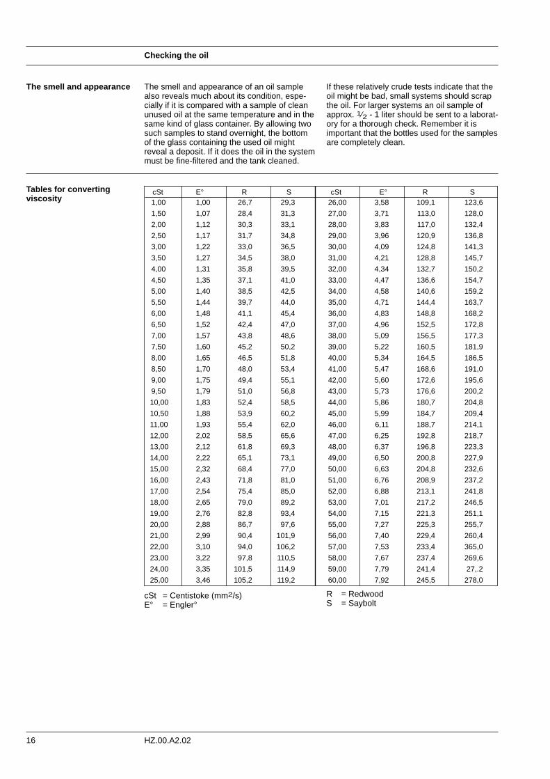
The smell and appearance The smell and appearance of an oil samplealso reveals much about its condition, espe-cially if it is compared with a sample of cleanunused oil at the same temperature and in thesame kind of glass container. By allowing twosuch samples to stand overnight, the bottomof the glass containing the used oil might reveal a deposit. If it does the oil in the systemmust be fine-filtered and the tank cleaned.
If these relatively crude tests indicate that theoil might be bad, small systems should scrapthe oil. For larger systems an oil sample ofapprox. 1⁄2 - 1 liter should be sent to a laborat-ory for a thorough check. Remember it isimportant that the bottles used for the samplesare completely clean.
Tables for convertingviscosity
cSt E° R S cSt E° R S1,00 1,00 26,7 29,3 26,00 3,58 109,1 123,6
1,50 1,07 28,4 31,3 27,00 3,71 113,0 128,0
2,00 1,12 30,3 33,1 28,00 3,83 117,0 132,4
2,50 1,17 31,7 34,8 29,00 3,96 120,9 136,8
3,00 1,22 33,0 36,5 30,00 4,09 124,8 141,3
3,50 1,27 34,5 38,0 31,00 4,21 128,8 145,7
4,00 1,31 35,8 39,5 32,00 4,34 132,7 150,2
4,50 1,35 37,1 41,0 33,00 4,47 136,6 154,7
5,00 1,40 38,5 42,5 34,00 4,58 140,6 159,2
5,50 1,44 39,7 44,0 35,00 4,71 144,4 163,7
6,00 1,48 41,1 45,4 36,00 4,83 148,8 168,2
6,50 1,52 42,4 47,0 37,00 4,96 152,5 172,8
7,00 1,57 43,8 48,6 38,00 5,09 156,5 177,3
7,50 1,60 45,2 50,2 39,00 5,22 160,5 181,9
8,00 1,65 46,5 51,8 40,00 5,34 164,5 186,5
8,50 1,70 48,0 53,4 41,00 5,47 168,6 191,0
9,00 1,75 49,4 55,1 42,00 5,60 172,6 195,6
9,50 1,79 51,0 56,8 43,00 5,73 176,6 200,2
10,00 1,83 52,4 58,5 44,00 5,86 180,7 204,8
10,50 1,88 53,9 60,2 45,00 5,99 184,7 209,4
11,00 1,93 55,4 62,0 46,00 6,11 188,7 214,1
12,00 2,02 58,5 65,6 47,00 6,25 192,8 218,7
13,00 2,12 61,8 69,3 48,00 6,37 196,8 223,3
14,00 2,22 65,1 73,1 49,00 6,50 200,8 227,9
15,00 2,32 68,4 77,0 50,00 6,63 204,8 232,6
16,00 2,43 71,8 81,0 51,00 6,76 208,9 237,2
17,00 2,54 75,4 85,0 52,00 6,88 213,1 241,8
18,00 2,65 79,0 89,2 53,00 7,01 217,2 246,5
19,00 2,76 82,8 93,4 54,00 7,15 221,3 251,1
20,00 2,88 86,7 97,6 55,00 7,27 225,3 255,7
21,00 2,99 90,4 101,9 56,00 7,40 229,4 260,4
22,00 3,10 94,0 106,2 57,00 7,53 233,4 365,0
23,00 3,22 97,8 110,5 58,00 7,67 237,4 269,6
24,00 3,35 101,5 114,9 59,00 7,79 241,4 27,.2
25,00 3,46 105,2 119,2 60,00 7,92 245,5 278,0
cSt = Centistoke (mm2/s)E° = Engler°
R = RedwoodS = Saybolt
Checking the oil
17HZ.00.A2.02
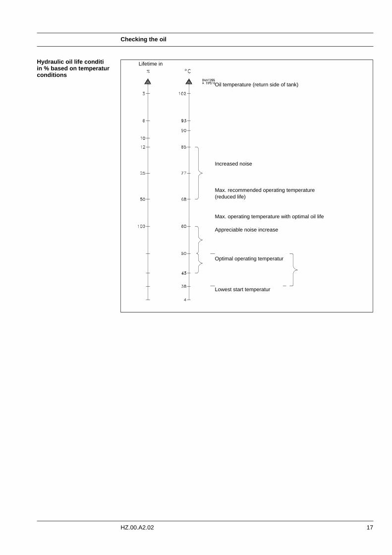
Hydraulic oil life conditi in % based on temperaturconditions
Oil temperature (return side of tank)
Increased noise
Max. recommended operating temperature(reduced life)
Max. operating temperature with optimal oil life
Appreciable noise increase
Optimal operating temperatur
Lowest start temperatur
Lifetime in
Installation of system
18 HZ.00.A2.02
After the designer has made calculations andselected the correct components, a number ofquestions have to be considered:
Where and how are the components to be placed?
This must be in strict accordance with,amongst others, the following factors:
- Suitability in relation to the work the motor orcylinder must perform.
- Easily accessible for installation and inspec-tion, and not least for repair or replacement. There is no such thing as a system that never needs to be repaired.
- Maximum heat emission is obtained by locating individual components, tanks, pipes,hoses and filters at the outer boundaries of the system. If pipes are bracketed to the machine frame or vehicle chassis, large amounts of heat will be given off.
- Noise suppression is the subject of environment legislation and much can be achieved by installing pumps and their motors on dampers and by using hoses between all moving/vibrating components and rigid parts.
Remember to follow catalogue instructions onpipes, hoses and fittings.
Remember that pipes which are welded or hot-bent must be thoroughly cleaned. Scaleetc. must be cleaned by wire brushing or bypickling followed by thorough flushing anddrying.
Remember it is very advisable to read thesupplier's directions and meet the require-ments contained in the installation instructionswhich nearly always accompany components.
Remember the three most important rules tobe followed when working with hydraulics are:
1. CLEANLINESS2. CLEANLINESS3. CLEANLINESS
Rule 1 Concerns cleanliness during the installation ofthe hydraulic system.
Hoses, pipes and fittings are never clean afterbeing worked on and must therefore alwaysbe cleaned immediately prior to installation.Pipes, including pipe bends, should preferablybe cleaned with a plug of crepe paper or lint-free cloth soaked in paraffin and blownthrough the pipe with compressed air. Thisprocess must be repeated with several plugsuntil a completely clean plug emerges. If pipeshave been hot-bent or welded they must becleaned by pickling in hydrochloric acid, flus-hed with cold and then hot water and dried. If the pipes are not to be fitted immediately,they must be lubricated with clean hydraulic oil and plugged, otherwise they will rust. Theblanking plugs fitted in all pumps, motors, val-ves, etc. must not be re-moved until just befo-re the components are installed.
Workshops, work stations, tools and clothingmust also be as clean as possible. Then thereis smoking! Apart from the fire risk, tobaccoash is harmful, it acts as an abrasive. Smokingshould therefore be prohibited.
Installation of system
19HZ.00.A2.02
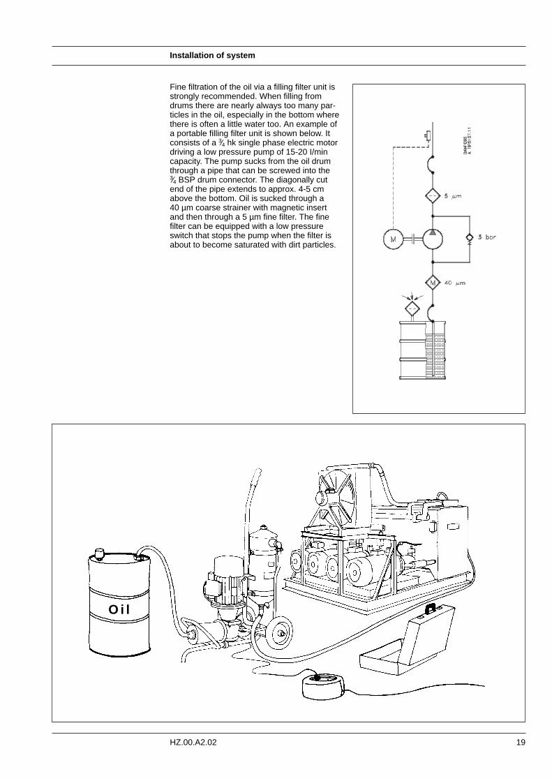
Fine filtration of the oil via a filling filter unit isstrongly recommended. When filling fromdrums there are nearly always too many par-ticles in the oil, especially in the bottom wherethere is often a little water too. An example ofa portable filling filter unit is shown below. Itconsists of a 3⁄4 hk single phase electric motordriving a low pressure pump of 15-20 I/mincapacity. The pump sucks from the oil drumthrough a pipe that can be screwed into the 3⁄4 BSP drum connector. The diagonally cutend of the pipe extends to approx. 4-5 cmabove the bottom. Oil is sucked through a 40 µm coarse strainer with magnetic insertand then through a 5 µm fine filter. The fine filter can be equipped with a low pressure switch that stops the pump when the filter isabout to become saturated with dirt particles.
O i l
Installation of system
20 HZ.00.A2.02
Rule 2 Concerns cleanliness during daily operation ofa hydraulic system.
Here, the main objective is to prevent the oilfrom becoming dirty. That is to say, filters(including air filters) must be clean - especiallypiston rods, shafts and shaft seals. It has beenproven that on every square centimetre ofpiston rod area, one dirt particle of more than10µm penetrates the cylinder. Imagine apiston rod of ø 50 mm, a length of just 100mm, and a velocity of 12 m/min. This meansabout 20.000 particles larger than 10 µm perminute! The tools used for filling must of course beperfectly clean and the oil filled into the
system must be filtered through filters of thesame fineness as the finest in the system, nor-mally 5 µm, but in any event no coarser than10 µm nominal. Oil in large drums is not nor-mally clean enough and, depending on thestorage, often contains water. Thereforedrums should be laid down during storage, orbetter still, should stand on a slant if kept out-doors so that water cannot collect around theplugs.
Rule 3 Concerns cleanliness during inspection andrepair.
Here also it goes without saying that every-thing should be kept as clean as pos-sible.Before a hydraulic component isremoved, both the component itself and theimmediate surroundings must be clean.All loose paint scale must be removed beforescrewed connections are dismantled and allopen parts, pipes, hoses, etc. must be blanked off with, for example, plastic bags
bound on so that dirt and dust cannot enterthe system when it is in standstill.
A hydraulic component must never be dis-mantled outdoors, but always in a closedworkshop equipped with necessary facilities,special equipment and trained personnel.
21
Starting up and running in of plant
HZ.00.A2.02
Correct starting up and running-in is of theutmost importance in ensuring that the systemruns for a long time without problems. All tooften, many systems and especially pumps"die" after only a few hours running, someafter only a few minutes, because the mostelementary steps have been overlooked. Oneexample is the non-observance of the cleanli-ness rules before and during start-up.
But despite even the best degree of cleanli-ness and care during installation, the pres-ence of dirt in a new system cannot be avoided. During running-in, wear particles willbe produced from all moving parts. It is there-fore important not to apply full load to thesystem before this dirt has been filtered out.
Let us look at our system which is fitted with aDanfoss pump type VPA and study the proce-dure for starting up:
1. Examine the tank to make sure it is per-fectly clean internally. If it is not, clean it out with a vacuum cleaner. Often during in-stalation, it is necessary to bore and tap a few extra holes which are not shown on the rawing.
2. Fill with clean oil of the correct type - through a filtering unit as described on page 23. If such a unit is not available, any filling funnels, cans, hoses must be thoroughly cleaned before they are used. Oil is filled through the return filter.
3. Before the pump is started, check the following:
a) Have all the flanges and screwed connections been tightened? (There is always one that hasn't).
b) Is the directional valve in its neutral position? (If it is not, the results can be catastrophic).
c) Is the pressure relief valve set at min-imum? (The result of a leak or a malfunc-tion is more violent at high pressure than at low pressure).
d) Does the pump rotate in the correct direction? (Nearly all pumps have a par-ticular direction of rotation: clockwise or counterclockwise looking on the end of the output shaft. The direction ought to beclearly marked with an arrow. Many pumps will not withstand being rotated in the wrong direction for more than a few minutes).
e) Is the pump and any suction line filled with oil? (Some pumps cannot withstand being rotated for more than a few minuteswithout oil in the pump housing).
4. Connect a vacuum meter in the suction line,as close to the pump as possible. Connect a 250 bar pressure gauge to the high pres-sure side of the system. Connect a 5 bar pressure gauge to the upper drain connecti-on. Pumps with a priming pump must be fit-ted with a 25 bar pressure gauge on the pri-ming pump take-off. If there is more than one pump on the same shaft, each pump must be fitted with these pressure gauges.
5. If possible, connect the discharge side of the pump to the tank, otherwise to a 5-10 litre container.
6. Set the pump displacement to at least 40% of maximum.
7. Start the pump (with a combustion engine at 800-900 r/min, or with an electric motor having short-duration start/stop functions). When the pump starts to suck (oil runs into the tank or container) stop the pump and connect its pressure outlet to the high pres-sure side of the system.
8. If the pump does not suck relatively quickly, check the following:
a) Is the suction line leaky? b) Is there free flow in the suction line? c) Does the pump rotate at all? d) Is the pump set for min. 40%
displacement?
9. Start the pump once more. Operate each directional valve for each motor or cylinder one after another, with a necessary bleed-ing at as low a pressure as possible. Repeat until the return oil in the tank does not foam and the motors and cylinders operate smoothly. Check the oil level frequently and refill with filtered oil.
10. A further frequent check: make sure that the suction pressure is at least 0.8 bar absolute, corresponding to 0.2 bar on the scale. After a short time, the drain pressuremust be max. 1 bar.
11. Set the pump for max. displacement and the motor for max. speed (but not higher than 3150 r/min continuous) and allow the system to run unloaded for about 20 min-utes, until the oil temperature has stabilized. Reverse the direction of the motor andthe travel of the cylinders frequently.
12. Set the individual pressure relief valves and the pump pressure control valve at thespecified pressure. Any schock valves in the system must be set at approx. 30-40 bar over the constant operating pressure. Check the oil temperature.
13. If required, the pump max. oil flow can be set using the flow limiter.
Starting up and running in of plant
22 HZ.00.A2.02
14. Remove the pressure gauges and vacuummeter and insert plugs in the connections. Replace filter inserts with new ones. Check the oil level.
15. If there is a large amount of oil (e.g. more than 100 litres in the system), an oil sample can be taken and sent to the oil supply firm for analysis.
16. The system can now be put to work.
23
Maintenance
HZ.00.A2.02
Nearly all hydraulic systems, stationary as wellas mobile, are accompanied by operatinginstructions, but the issue of maintenanceinstructions is just as important. To be able tocorrectly maintain a hydraulic system, the
The suction line must be inspected for dam-age and sharp bends that reduce the bore ofthe pipe and create noisy cavitation. Screwedconnections must be inspected for leaks andtightened if necessary.
The regular inspection of a hydraulic system ismore economical than making repairs when afault occurs. If a fault does occur, the wholesystem ought to be checked rather than justthe defective component. Regular planned preventative maintenance ofthe system after a certain number of operating
The oil level must be correct and the oil mustbe of the prescribed type and viscosity. On large systems it pays to send oil samples foranalysis at regular intervals. Factors of specialimportance in deciding whether the oil cancontinue to be used are the rise in oil viscosity,the acidity number and the content of impur-ities. If there is no special equipment availab-le,
the oil by looking at its colour. Poor oil can bedark, it can smell rancid or burnt; or it can beyellow, unclear or milky, which indicates thepresence of air or emulsified water. And ofcourse the oil might contain free microscopicmetal particles and other foreign substances.
hours and the scheduled replacement ofimportant seals ensures the avoidance ofcostly operational stops.
To avoid forgetting something, a routine fol-lowing the direction of oil flow should be ad-opted, beginning with:
customer (end user) must know what has tobe done. The transfer of this knowledge is theresponsibility of the manufacturer.
Periodic inspection
The tank
Rubber or plastic hoses are suspect becausethey often become contracted by vacuumwhen the oil is hot. Such items should bereplaced with pipes or armoured hoses.
The suction line
The pump
The return line and return filter
The pump must be inspected for shaft sealand other leakage. If the pump is driven by V-belt, this should be examined to ensure that itis not worn and is correctly tensioned. The dif-ferent circuits on the pressure side must beexamined individually, following the directionof oil flow. There must be no leaks. Look on the floor
The return line and return filter must be in-spected for leaks, etc. and the filter must bechecked. If the filter has a dirt indicator thecondition of the filter can easily be seen. If there is no dirt indicator, the filter has to betaken out to see whether it needs cleaning orreplacement.
under the vehicle for oil patches. The finger-tips are good instruments for sensing faults,the ears too - by using a screwdriver or similartool as a stethoscope, irregularities which might later cause breakdown can often beheard.
Trouble shooting
24 HZ.00.A2.02
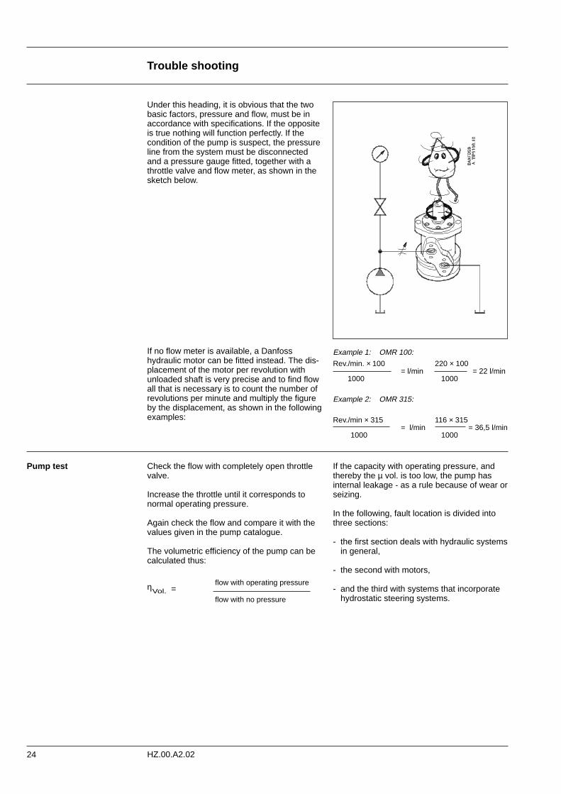
Under this heading, it is obvious that the twobasic factors, pressure and flow, must be inaccordance with specifications. If the oppositeis true nothing will function perfectly. If thecondition of the pump is suspect, the pressureline from the system must be disconnectedand a pressure gauge fitted, together with athrottle valve and flow meter, as shown in thesketch below.
If no flow meter is available, a Danfosshydraulic motor can be fitted instead. The dis-placement of the motor per revolution withunloaded shaft is very precise and to find flowall that is necessary is to count the number ofrevolutions per minute and multiply the figureby the displacement, as shown in the followingexamples:
Example 1: OMR 100:
Rev./min. × 100 220 × 100= l/min = 22 l/min
1000 1000
Example 2: OMR 315:
Rev./min × 315 116 × 315= l/min = 36,5 l/min
1000 1000
Pump test If the capacity with operating pressure, andthereby the µ vol. is too low, the pump hasinternal leakage - as a rule because of wear orseizing.
In the following, fault location is divided intothree sections:
- the first section deals with hydraulic systemsin general,
- the second with motors,
- and the third with systems that incorporate hydrostatic steering systems.
Check the flow with completely open throttlevalve.
Increase the throttle until it corresponds tonormal operating pressure.
Again check the flow and compare it with thevalues given in the pump catalogue.
The volumetric efficiency of the pump can becalculated thus:
flow with operating pressureηVol. = flow with no pressure
25
Trouble shooting general
HZ.00.A2.02
THINK before starting trouble shootingEvery fault location process should follow alogical and systematical order. Usually it iswisest to start at the beginning:
- Is the oil level correct when the pump is operating?
- Is the condition of oil and filters acceptable?- Are pressure, flow and flow direction as
specified? - Is the oil temperature too high or too low
(oil viscosity)? - Are there any unrequired vibrations or noise
(cavitation)?
If the driver of the vehicle is available ask him:
- what type of fault it is and how it affects the system,
- how long he has felt that something was wrong
- whether he has "fiddled" with the compon-nents
- whether he has any hydraulic and electrical diagrams available.
Diagrams are often found in the instructionsincluded with vehicles/machines. Unfortunate-ly they are often so technical that they are notof much use in a fault location situation. How-ever, the order of and the connections betw-een the individual components are oftenshown.
When a defect component has, with certainty,been found both the component and its sur-roundings must be cleaned before removal.Loose paint must also be removed from pipesand fittings.
Holes, hoses and pipe ends must be blankedoff with plugs or sealed with, for example,plasic bags after removal to avoid the entry ofdirt during standstill. Never dismantle hydrauliccomponents outside. We recommend thatrepairs be carried out in a workshop on a clean workbench perhaps covered with news-paper.
Make sure that a Danfoss service manual dealing with the product in question is handy.Follow the instructions word for word bothwhen dismantling and assembling because ifthese instructions are not followed closely serious faults may develop. NB. In somecases special tools are necessary for assem-bling. Our service manuals give full guidanceas to when this is the case.
Fault location tips
26 HZ.00.A2.02
Fault
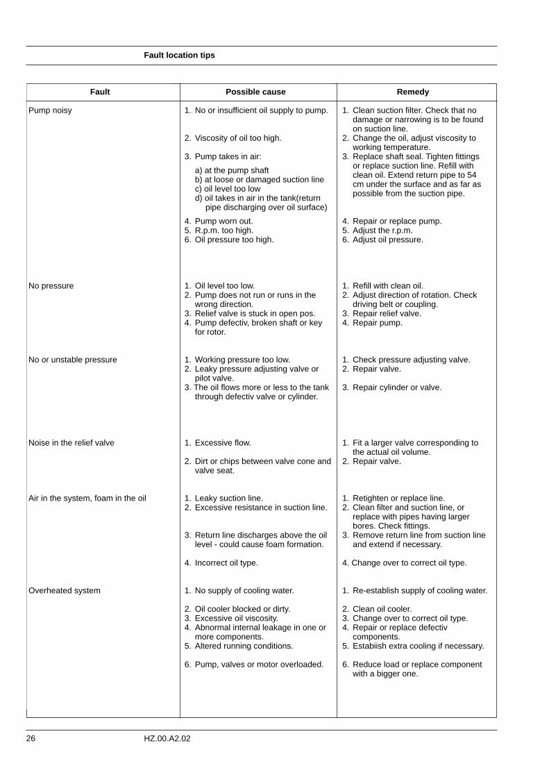
Pump noisy
No pressure
No or unstable pressure
Noise in the relief valve
Air in the system, foam in the oil
Overheated system
Possible cause
1. No or insufficient oil supply to pump.
2. Viscosity of oil too high.
3. Pump takes in air:
a) at the pump shaft b) at loose or damaged suction line c) oil level too low d) oil takes in air in the tank(return
pipe discharging over oil surface)
4. Pump worn out.5. R.p.m. too high.6. Oil pressure too high.
1. Oil level too low.2. Pump does not run or runs in the
wrong direction.3. Relief valve is stuck in open pos.4. Pump defectiv, broken shaft or key
for rotor.
1. Working pressure too low.2. Leaky pressure adjusting valve or
pilot valve.3. The oil flows more or less to the tank
through defectiv valve or cylinder.
1. Excessive flow.
2. Dirt or chips between valve cone andvalve seat.
1. Leaky suction line.2. Excessive resistance in suction line.
3. Return line discharges above the oil level - could cause foam formation.
4. Incorrect oil type.
1. No supply of cooling water.
2. Oil cooler blocked or dirty.3. Excessive oil viscosity.4. Abnormal internal leakage in one or
more components.5. Altered running conditions.
6. Pump, valves or motor overloaded.
Remedy
1. Clean suction filter. Check that no damage or narrowing is to be found on suction line.
2. Change the oil, adjust viscosity to working temperature.
3. Replace shaft seal. Tighten fittings or replace suction line. Refill with clean oil. Extend return pipe to 54 cm under the surface and as far as possible from the suction pipe.
4. Repair or replace pump.5. Adjust the r.p.m.6. Adjust oil pressure.
1. Refill with clean oil.2. Adjust direction of rotation. Check
driving belt or coupling.3. Repair relief valve.4. Repair pump.
1. Check pressure adjusting valve.2. Repair valve.
3. Repair cylinder or valve.
1. Fit a larger valve corresponding to the actual oil volume.
2. Repair valve.
1. Retighten or replace line.2. Clean filter and suction line, or
replace with pipes having larger bores. Check fittings.
3. Remove return line from suction line and extend if necessary.
4. Change over to correct oil type.
1. Re-establish supply of cooling water.
2. Clean oil cooler.3. Change over to correct oil type.4. Repair or replace defectiv
components.5. Estabiish extra cooling if necessary.
6. Reduce load or replace component with a bigger one.
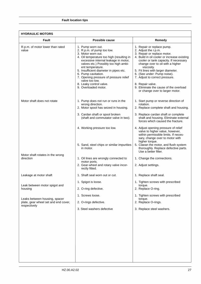
HYDRAULIC MOTORS
Fault location tips
27HZ.00.A2.02
Fault
R.p.m. of motor lower than ratedvalue
Motor shaft does not rotate
Motor shaft rotates in the wrong direction
Leakage at motor shaft
Leak between motor spigot and housing
Leaks between housing, spacer plate, gear wheel set and end cover,respectively
Remedy
1. Repair or replace pump.2. Adjust the r.p.m.3. Repair or replace motor.4. Build in oil cooler or increase existing
cooler or tank capacity. If necessary change over to oil with a higher
viscosity.5. Fit lines with larger diameter.6. (See under: Pump noise).7. Adjust to correct pressure.
8. Repair valve.9. Eliminate the cause of the overload
or change over to larger motor.
1. Start pump or reverse direction of rotation.
2. Replace complete shaft and housing.
3. Replace cardan shaft or complete shaft and housing. Eliminate externalforces which caused the fracture.
4. Adjust opening pressure of relief valve to higher value, however, within permissible limits. If neces-sary, change over to motor with higher torque.
5. Claean the motor, and flush system thoroughly. Replace defective parts. Use a better filter.
1. Change the connections.
2. Adjust settings.
1. Replace shaft seal.
1. Tighten screws with prescribed torque.
2. Replace O-ring.
1. Tighten screws with prescribed torque.
2. Replace O-rings.
3. Replace steel washers.
Possible cause
1. Pump worn out.2. R.p.m. of pump too low.3. Motor worn out.4. Oil temperature too high (resulting in
excessive internal leakage in motor, valves etc.) Possibly too high ambi-ent temperature.
5. Insufficient diameter in pipes etc.6. Pump cavitation.7. Opening pressure of pressure relief
valve too low.8. Leaky control valve.9. Overloaded motor.
1. Pump does not run or runs in the wrong direction.
2. Motor spool has seized in housing.
3. Cardan shaft or spool broken (shaft and commutator valve in two).
4. Working pressure too low.
5. Sand, steel chips or similar impuritiesin motor.
1. Oil lines are wrongly connected to motor ports.
2. Gear-wheel and rotary valve incor-rectly fitted.
1. Shaft seal worn out or cut.
1. Spigot is loose.
2. O-ring defective.
1. Screws loose.
2. O-rings defective.
3. Steel washers defective
Fault location tips
28 HZ.00.A2.02
Steering systems withOSPB-OSPC-OVP/OVR-OLS
The following quick methods of testing steering systems can be recommended:
1. Start the motor (pump) and let it run for a couple of minutes.
2. Drive slowly in a figure of eight. Pay special attention to any shaking or vibration in the steering wheel or steered wheels. See whether the steering wheel movements are immediately followed by a corresponding correction of the wheel movements, without any "motoring" tendencies.
3. Stop the vehicle and turn the steering wheelwith small quick movements in both direc-tions. Let go of the steering wheel after each movement. The steering wheel must immediately go back to the neutral position i.e. there should be no "motoring" tendencies.
4. While the vehicle is still stationary turn the steering wheel from stop to stop. Count the number of times the steering wheel turns in both directions. Note: It must be possible to
turn the steering wheel with one fin-ger.
Stop the motor (pump) and again turn the steering wheel from stop to stop. Again count the number of turns and compare with previous figures. If there is a large dif-ference (1 turn or more) the leakage in the cylinder, gear wheel set, shock valve or suction valve is too large.
With larger vehicles where there is no emergency steering function, turn the steering wheel whilst the motor is idling.
5. If there is a leak, remove a hose from one of the cylinder ends and plug this and the hose. Try to turn the steering wheel again. If the wheel cannot turn the cylinder is defective. If this is not the case the steering
unit or valve block is defective.
Steering unitsOSPB - OSPC - OVP/OVR - OLS
Fault location tips
29HZ.00.A2.02
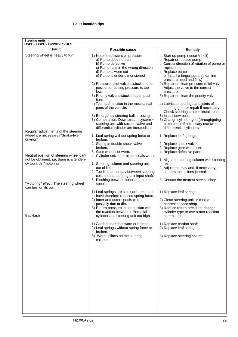
Fault
Steering wheel is heavy to turn
Regular adjustments of the steeringwheel are necessary ("Snake-like driving")
Neutral position of steering wheel can-not be obtained, i.e. there is a tenden-cy towards "motoring"
"Motoring" effect. The steering wheelcan turn on its own.
Backlash
Possible cause
1) No or insufficient oil pressure a) Pump does not run b) Pump defective c) Pump runs in the wrong direction d) Pump is worn out e) Pump is under dimensioned
2) Pressure relief valve is stuck in openposition or setting pressure is too low.
3) Priority valve is stuck in open posi-tion.
4) Too much friction in the mechanical pans of the vehicle.
5) Emergency steering balls missing.6) Combination: Downstream system +
steering unit with suction valve and differential cylinder are inexpedient.
1. Leaf spring without spring force or broken.
2. Spring in double shock valve broken.
3. Gear wheel set worn.4. Cylinder seized or piston seals worn.
1. Steering column and steering unit out of line.
2. Too Iittle or no play between steeringcolumn and steering unit input shaft.
3. Pinching between inner and outer spools.
1) Leaf springs are stuck or broken andhave therefore reduced spring force.
2) Inner and outer spools pinch, possibly due to dirt.
3) Return pressure in connection with. the reaction between dfflerential cylinder and steering unit too high.
1) Cardan shaft fork worn or broken.2) Leaf springs without spring force or
broken.3) Worn splines on the steering
column.
Remedy
a. Start up pump (loose V-belt)b. Repair or replace pumpc. Correct direction of rotation of pump or
replace pumpd. Replace pump
e. Install a larger pump (examine pressure need and flow)
2) Repalr or clean pressure relief valve. Adjust the valve to the correct pressure.
3) Repair or clean the priority valve.
4) Lubricate bearings and joints of steering gear or repair if necessary Check steering column installation.
5) Install new balls.6) Change cylinder type (throughgoing
piston rod). If necessary use two differerential cylinders.
1. Replace leaf springs.
2. Replace shock valve.3. Replace gear wheel set.4. Replace defective parts.
1. Align the steering column with steeringunit.
2. Adjust the play and, if necessary, shorten the splines journal.
3. Contact the nearest service shop.
1) Replace leaf springs.
2) Clean steering unit or contact the nearest service shop.
3) Reduce return pressure, change cylinder type or use a non-reaction control unit.
1) Replace cardan shaft.2) Replace leaf springs.
3) Replace steering column.
Steering unitsOSPB - OSPC - OVP/OVR - OLS
Fault location tips
30 HZ.00.A2.02
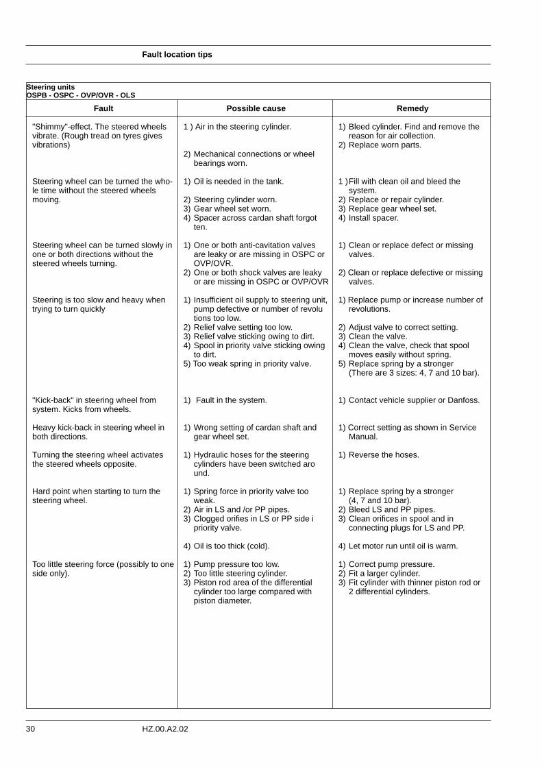
Fault
"Shimmy"-effect. The steered wheelsvibrate. (Rough tread on tyres givesvibrations)
Steering wheel can be turned the who-le time without the steered wheelsmoving.
Steering wheel can be turned slowly inone or both directions without the steered wheels turning.
Steering is too slow and heavy whentrying to turn quickly
"Kick-back" in steering wheel fromsystem. Kicks from wheels.
Heavy kick-back in steering wheel inboth directions.
Turning the steering wheel activatesthe steered wheels opposite.
Hard point when starting to turn thesteering wheel.
Too little steering force (possibly to oneside only).
Remedy
1) Bleed cylinder. Find and remove the reason for air collection.
2) Replace worn parts.
1 )Fill with clean oil and bleed the system.
2) Replace or repair cylinder. 3) Replace gear wheel set. 4) Install spacer.
1) Clean or replace defect or missing valves.
2) Clean or replace defective or missing valves.
1) Replace pump or increase number of revolutions.
2) Adjust valve to correct setting. 3) Clean the valve. 4) Clean the valve, check that spool
moves easily without spring.5) Replace spring by a stronger
(There are 3 sizes: 4, 7 and 10 bar).
1) Contact vehicle supplier or Danfoss.
1) Correct setting as shown in Service Manual.
1) Reverse the hoses.
1) Replace spring by a stronger (4, 7 and 10 bar).
2) Bleed LS and PP pipes.3) Clean orifices in spool and in
connecting plugs for LS and PP.
4) Let motor run until oil is warm.
1) Correct pump pressure.2) Fit a larger cylinder.3) Fit cylinder with thinner piston rod or
2 differential cylinders.
Possible cause
1 ) Air in the steering cylinder.
2) Mechanical connections or wheel bearings worn.
1) Oil is needed in the tank.
2) Steering cylinder worn.3) Gear wheel set worn.4) Spacer across cardan shaft forgot
ten.
1) One or both anti-cavitation valves are leaky or are missing in OSPC or OVP/OVR.
2) One or both shock valves are leaky or are missing in OSPC or OVP/OVR
1) Insufficient oil supply to steering unit,pump defective or number of revolutions too low.
2) Relief valve setting too low.3) Relief valve sticking owing to dirt.4) Spool in priority valve sticking owing
to dirt.5) Too weak spring in priority valve.
1) Fault in the system.
1) Wrong setting of cardan shaft and gear wheel set.
1) Hydraulic hoses for the steering cylinders have been switched around.
1) Spring force in priority valve too weak.
2) Air in LS and /or PP pipes.3) Clogged orifies in LS or PP side i
priority valve.
4) Oil is too thick (cold).
1) Pump pressure too low.2) Too little steering cylinder.3) Piston rod area of the differential
cylinder too large compared with piston diameter.
Steering units OSPB - OSPC - OVP/OVR - OLS
Fault location tips
31HZ.00.A2.02
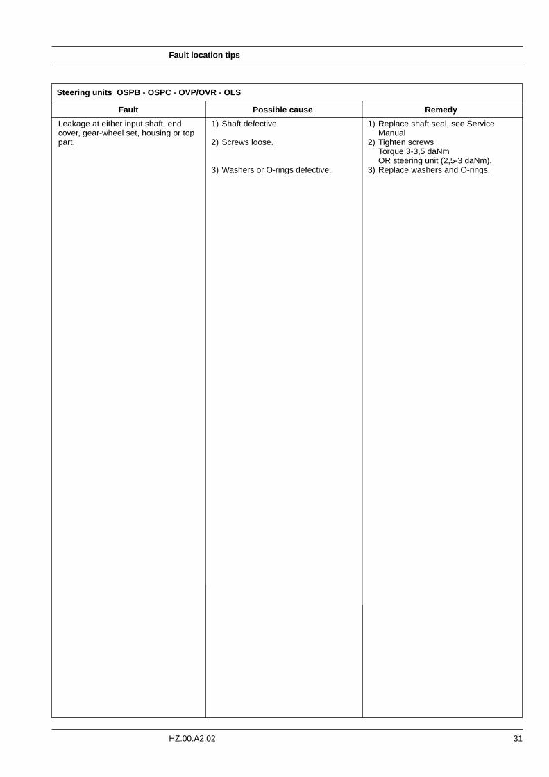
Fault
Leakage at either input shaft, endcover, gear-wheel set, housing or toppart.
Possible cause
1) Shaft defective
2) Screws loose.
3) Washers or O-rings defective.
Remedy
1) Replace shaft seal, see Service Manual
2) Tighten screwsTorque 3-3,5 daNm OR steering unit (2,5-3 daNm).
3) Replace washers and O-rings.
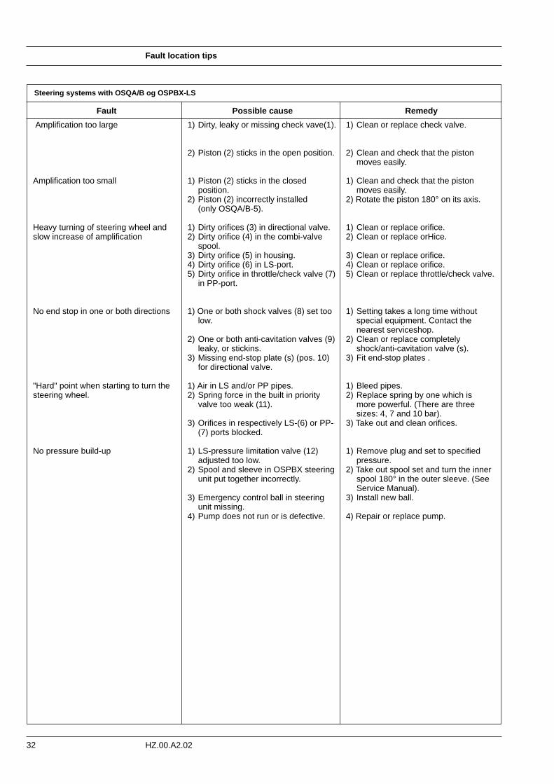
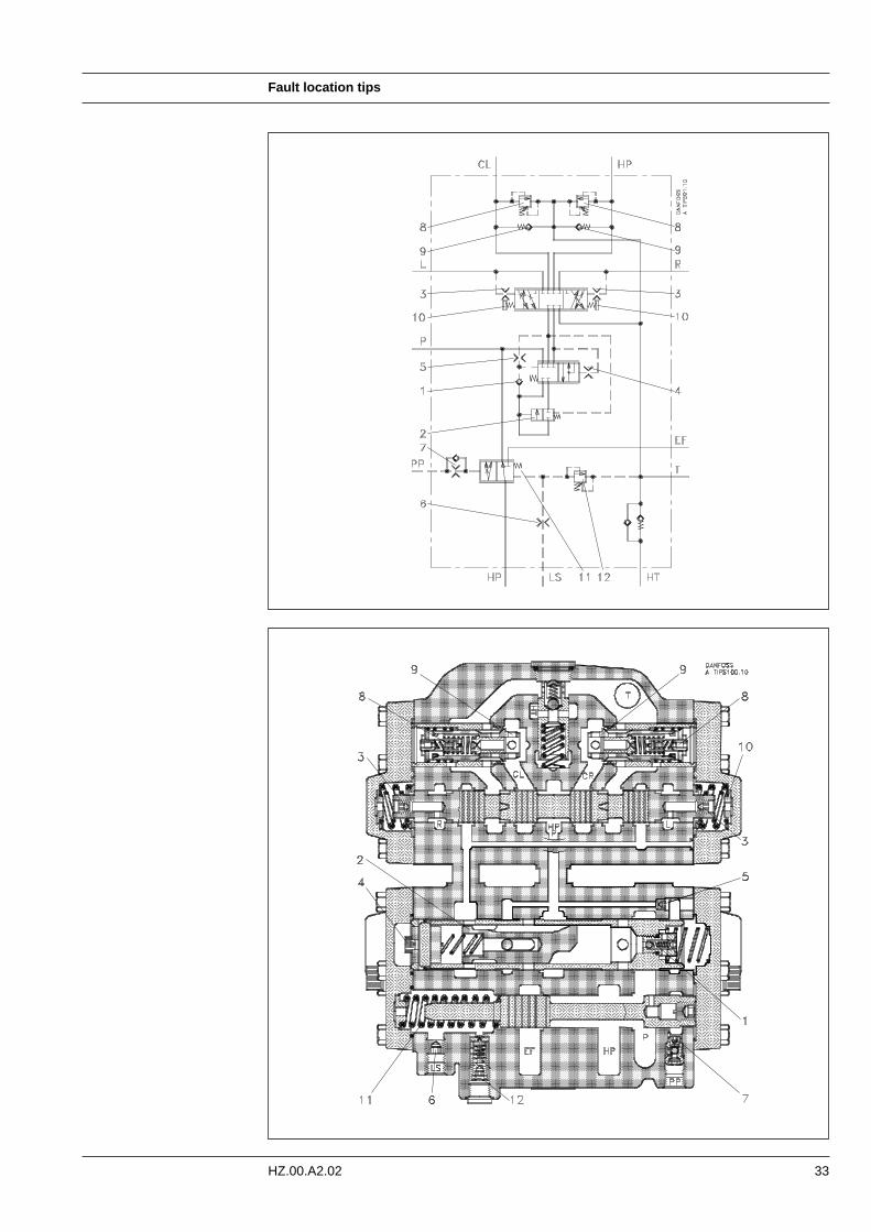
Steering systems with OSQA/B og OSPBX-LS
Fault location tips
32 HZ.00.A2.02
Possible cause
1) Dirty, leaky or missing check vave(1).
2) Piston (2) sticks in the open position.
1) Piston (2) sticks in the closed position.
2) Piston (2) incorrectly installed (only OSQA/B-5).
1) Dirty orifices (3) in directional valve.2) Dirty orifice (4) in the combi-valve
spool.3) Dirty orifice (5) in housing.4) Dirty orifice (6) in LS-port.5) Dirty orifice in throttle/check valve (7)
in PP-port.
1) One or both shock valves (8) set too low.
2) One or both anti-cavitation valves (9) leaky, or stickins.
3) Missing end-stop plate (s) (pos. 10) for directional valve.
1) Air in LS and/or PP pipes.2) Spring force in the built in priority
valve too weak (11).
3) Orifices in respectively LS-(6) or PP-(7) ports blocked.
1) LS-pressure limitation valve (12) adjusted too low.
2) Spool and sleeve in OSPBX steering unit put together incorrectly.
3) Emergency control ball in steering unit missing.
4) Pump does not run or is defective.
Remedy
1) Clean or replace check valve.
2) Clean and check that the piston moves easily.
1) Clean and check that the piston moves easily.
2) Rotate the piston 180° on its axis.
1) Clean or replace orifice.2) Clean or replace orHice.
3) Clean or replace orifice.4) Clean or replace orifice.5) Clean or replace throttle/check valve.
1) Setting takes a long time without special equipment. Contact the nearest serviceshop.
2) Clean or replace completely shock/anti-cavitation valve (s).
3) Fit end-stop plates .
1) Bleed pipes.2) Replace spring by one which is
more powerful. (There are three sizes: 4, 7 and 10 bar).
3) Take out and clean orifices.
1) Remove plug and set to specified pressure.
2) Take out spool set and turn the inner spool 180° in the outer sleeve. (See Service Manual).
3) Install new ball.
4) Repair or replace pump.
Fault
Amplification too large
Amplification too small
Heavy turning of steering wheel andslow increase of amplification
No end stop in one or both directions
"Hard" point when starting to turn thesteering wheel.
No pressure build-up
Fault location tips
33HZ.00.A2.02
Repair and testing
34 HZ.00.A2.02
Repair After fault location has revealed which systemcomponent is defective, that component mustbe removed and possibly replaced as a newor repaired one. Before removal, both thecomponent and its surroundings must be cleaned and hoses or pipe ends blanked offwith plugs or sealed with plastic bags, etc. toavoid the entry of dirt during standstill. Thedecision now to be made is whether the com-ponent is to be repaired domestically or by theproducer. If the concerned component is fromDanfoss, we recommend that it be repaired inone of our many service workshops (see liston back page). This particularly applies tomore complicated components like steeringunits, flow amplifiers, pumps and proportionalvalves. For safety reasons, these all needtesting with special equipment after repair.
Of course situations can occur where components require immediate repair. Werecommend most strongly that in such circumstances repairs be carried out only invery clean surroundings, in suitable premiseson a tidy workbench perhaps covered withnewspaper.
Important! Dismantling and assembly must only be per-formed if the repairer has the associated Dan-foss service manuals. If these are not follow-ed, serious faults might develop;
faults that could give rise to accidents. This is more than likely with steering compon-ents and proportional valves.
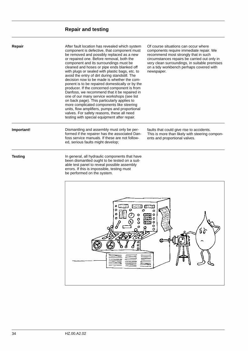
Testing In general, all hydraulic components that havebeen dismantled ought to be tested on a suit-able test panel to reveal possible assemblyerrors. If this is impossible, testing mustbe performed on the system.
35
Symbols and Tables
HZ.00.A2.02
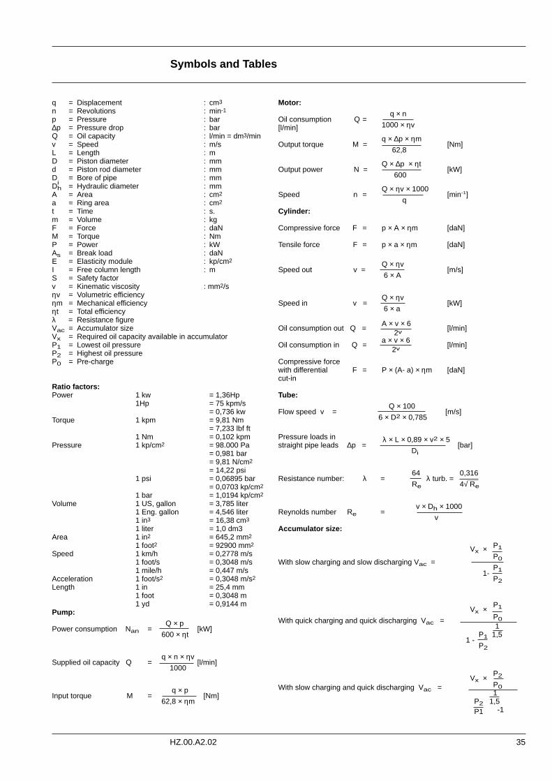
q = Displacement : cm3
n = Revolutions : min-1
p = Pressure : bar∆p = Pressure drop : barQ = Oil capacity : l/min = dm3/minv = Speed : m/sL = Length : mD = Piston diameter : mmd = Piston rod diameter : mmD
i= Bore of pipe : mm
Dh = Hydraulic diameter : mmA = Area : cm2
a = Ring area : cm2
t = Time : s.m = Volume : kg F = Force : daNM = Torque : NmP = Power : kWAs = Break load : daNE = Elasticity module : kp/cm2
I = Free column length : mS = Safety factorv = Kinematic viscosity : mm2/sηv = Volumetric efficiencyηm = Mechanical efficiencyηt = Total efficiencyλ = Resistance figureVac = Accumulator sizeVx = Required oil capacity available in accumulatorP1 = Lowest oil pressureP2 = Highest oil pressureP0 = Pre-charge
Ratio factors:Power 1 kw = 1,36Hp
1Hp = 75 kpm/s= 0,736 kw
Torque 1 kpm = 9,81 Nm= 7,233 lbf ft
1 Nm = 0,102 kpmPressure 1 kp/cm2 = 98.000 Pa
= 0,981 bar= 9,81 N/cm2
= 14,22 psi1 psi = 0,06895 bar
= 0,0703 kp/cm2
1 bar = 1,0194 kp/cm2
Volume 1 US, gallon = 3,785 liter1 Eng. gallon = 4,546 liter1 in3 = 16,38 cm3
1 liter = 1,0 dm3Area 1 in2 = 645,2 mm2
1 foot2 = 92900 mm2
Speed 1 km/h = 0,2778 m/s1 foot/s = 0,3048 m/s1 mile/h = 0,447 m/s
Acceleration 1 foot/s2 = 0,3048 m/s2
Length 1 in = 25,4 mm1 foot = 0,3048 m1 yd = 0,9144 m
Pump:
Q × pPower consumption Nan = [kW]
600 × ηt
q × n × ηvSupplied oil capacity Q = [l/min]
1000
q × pInput torque M = [Nm]
62,8 × ηm
Motor:
q × nOil consumption Q =[l/min] 1000 × ηv
q × ∆p × ηmOutput torque M = [Nm]
62,8
Q × ∆p × ηtOutput power N = [kW]
600
Q × ηv × 1000Speed n = [min-1]
q
Cylinder:
Compressive force F = p × A × ηm [daN]
Tensile force F = p × a × ηm [daN]
Q × ηvSpeed out v = [m/s]
6 × A
Q × ηvSpeed in v = [kW]
6 × a
Oil consumption out Q =A × v × 6
[l/min]2v
Oil consumption in Q =a × v × 6
[l/min]2v
Compressive forcewith differential F = P × (A- a) × ηm [daN]cut-in
Tube:
Q × 100Flow speed v = [m/s]
6 × D2 × 0,785
Pressure loads in λ × L × 0,89 × v2 × 5 straight pipe leads ∆p = [bar]
Di
64 0,316Resistance number: λ = λ turb. =
Re 4√ Re
v × Dh × 1000Reynolds number Re =
v
Accumulator size:
P1Vx ×P0With slow charging and slow discharging Vac =P11-P2
P1Vx ×P0With quick charging and quick discharging Vac =1
P1 1,5 1 -
P2
P2Vx ×P0With slow charging and quick discharging Vac =1
P2 1,5-1P1
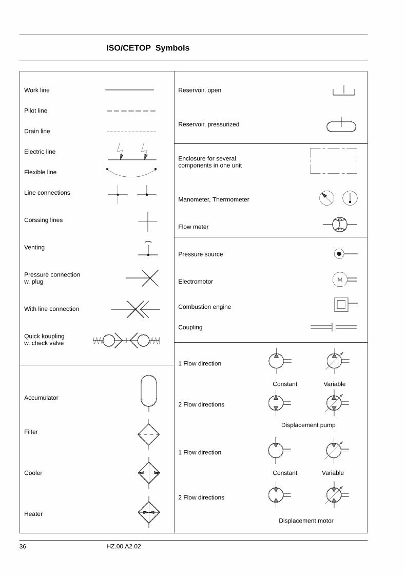
ISO/CETOP Symbols
36 HZ.00.A2.02
Reservoir, open
Reservoir, pressurized
Enclosure for several components in one unit
Manometer, Thermometer
Flow meter
Pressure source
Electromotor
Combustion engine
Coupling
1 Flow direction
Constant Variable
2 Flow directions
Displacement pump
1 Flow direction
Constant Variable
2 Flow directions
Displacement motor
Work line
Pilot line
Drain line
Electric line
Flexible line
Line connections
Corssing lines
Venting
Pressure connectionw. plug
With line connection
Quick koupling w. check valve
Accumulator
Filter
Cooler
Heater
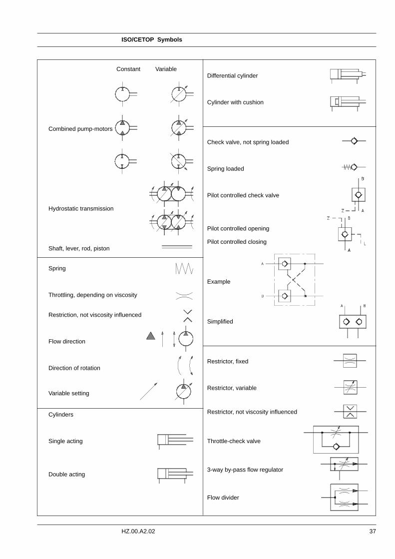
ISO/CETOP Symbols
37HZ.00.A2.02
Constant Variable
Combined pump-motors
Hydrostatic transmission
Shaft, lever, rod, piston
Spring
Throttling, depending on viscosity
Restriction, not viscosity influenced
Flow direction
Direction of rotation
Variable setting
Cylinders
Single acting
Double acting
Differential cylinder
Cylinder with cushion
Check valve, not spring loaded
Spring loaded
Pilot controlled check valve
Pilot controlled opening
Pilot controlled closing
Example
Simplified
Restrictor, fixed
Restrictor, variable
Restrictor, not viscosity influenced
Throttle-check valve
3-way by-pass flow regulator
Flow divider
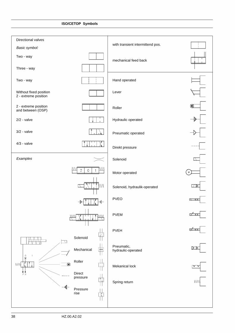
ISO/CETOP Symbols
38 HZ.00.A2.02
with transient intermittend pos.
mechanical feed back
Hand operated
Lever
Roller
Hydraulic operated
Pneumatic operated
Direkt pressure
Solenoid
Motor operated
Solenoid, hydraulik-operated
PVEO
PVEM
PVEH
Pneumatic,hydraulic-operated
Mekanical lock
Spring return
Directional valves
Basic symbol:
Two - way
Three - way
Two - way
Without fixed position2 - extreme position
2 - extreme positionand between (OSP)
2/2 - valve
3/2 - valve
4/3 - valve
Examples
Solenoid
Mechanical
Roller
Directpressure
Pressurerise
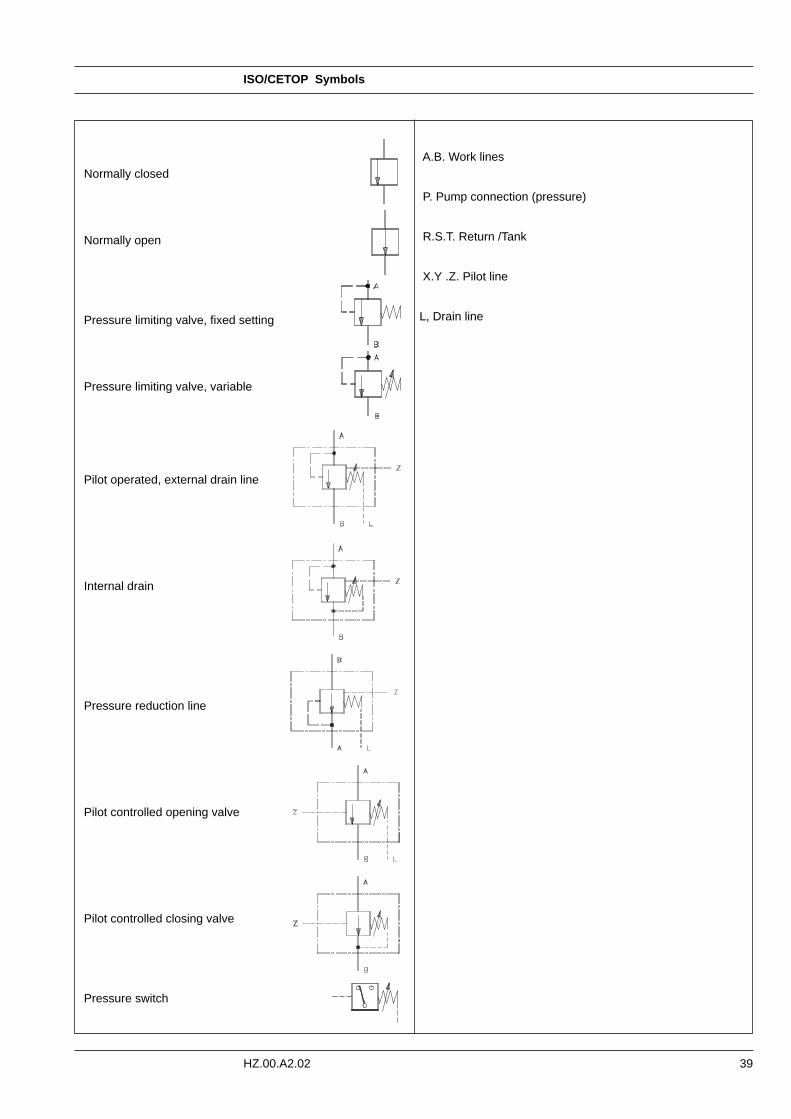
ISO/CETOP Symbols
39HZ.00.A2.02
A.B. Work lines
P. Pump connection (pressure)
R.S.T. Return /Tank
X.Y .Z. Pilot line
L, Drain line
Normally closed
Normally open
Pressure limiting valve, fixed setting
Pressure limiting valve, variable
Pilot operated, external drain line
Internal drain
Pressure reduction line
Pilot controlled opening valve
Pilot controlled closing valve
Pressure switch
Danfoss Hydraulics
40 HZ.00.A2.02 © Danfoss 08/98
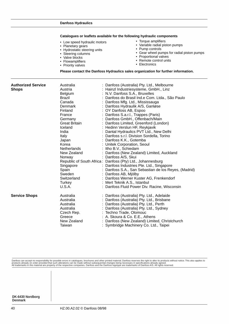
• Low speed hydraulic motors• Planetary gears• Hydrostatic steering units• Steering columns• Valve blocks• Flowamplifiers• Priority valves
• Torque amplifiers• Variable radial piston pumps• Pump controls• Gear wheel pumps for radial piston pumps • Proportional valves• Remote control units• Electronics
Catalogues or leaflets available for the following hydraulic components
Please contact the Danfoss Hydraulics sales organization for further information.
Danfoss can accept no responsibility for possible errors in catalogues, brochures and other printed material. Danfoss reserves the right to alter its products without notice. This also applies toproducts already on order provided that such alterations can be made without subsequential changes being necessary in specifications already agreed.All trademarks in this material are property of the respective companies. Danfoss and the Danfoss logotype are trademarks of Danfoss A/S. All rights reserved.
DK-6430 NordborgDenmark
Authorized ServiceShops
Service Shops Australia : Danfoss (Australia) Pty. Ltd., AdelaideAustralia : Danfoss (Australia) Pty. Ltd., BrisbaneAustralia : Danfoss (Australia) Pty. Ltd., PerthAustralia : Danfoss (Australia) Pty. Ltd., SydneyCzech Rep. : Techno Trade, OlomoucGreece : A. Skoura & Co. E.E., AthensNew Zealand : Danfoss (New Zealand) Limited, ChristchurchTaiwan : Symbridge Machinery Co. Ltd., Taipei
Australia : Danfoss (Australia) Pty. Ltd., Melbourne Austria : Hainzl Industriesysteme, GmbH., Linz Belgium : N.V. Danfoss S.A., Bruxelles Brazil : Danfoss do Brasil Ind.e Com. Ltda., São PauloCanada : Danfoss Mfg. Ltd., Mississauga Denmark : Danfoss Hydraulik A/S, Ganløse Finland : OY Danfoss AB, Espoo France : Danfoss S.a.r.l., Trappes (Paris) Germany : Danfoss GmbH., Offenbach/MainGreat Britain : Danfoss Limited, Greenford (London)Iceland : Hedinn Verslun HF, Reykjavik India : Dantal Hydraulics PVT Ltd., New DelhiItaly : Danfoss s.r.l. Division Sordella, TorinoJapan : Danfoss K.K., GotembaKorea : Unitek Corporation, SeoulNetherlands : Itho B.V., Schiedam New Zealand : Danfoss (New Zealand) Limited, AucklandNorway : Danfoss A/S, Skui Republic of South Africa : Danfoss (Pty) Ltd., JohannesburgSingapore : Danfoss Industries Pte. Ltd., Singapore Spain : Danfoss S.A., San Sebastian de los Reyes, (Madrid)Sweden : Danfoss AB, Mjölby Switzerland : Danfoss Werner Kuster AG, Frenkendorf Turkey : Mert Teknik A.S., Istanbul U.S.A. : Danfoss Fluid Power Div. Racine, Wisconsin