FactoryCAD Tutorial
30
FactoryCAD 6.2 Tutorial February 22, 2000 Better Factories Faster from
Transcript of FactoryCAD Tutorial

FactoryCAD 6.2 Tutorial
February 22, 2000
Better Factories Faster
from

2 FactoryCAD Tutorial
Copyright Notice and Terms of Use
Copyright © 1999-2000 Engineering Animation, Inc. (EAI) All rights reserved.
This documentation is licensed to the licensee of the EAI software product ("the Licensee") pursuant tothe terms and conditions set forth below and in the applicable EAI software license agreement. Thedocumentation at all times remains the property of EAI. The information contained in this documentationis considered confidential to EAI and shall not be disclosed to any third party except as expresslyauthorized by EAI.
Disclaimer of Warranties and Limitations on Liability
EAI MAKES NO WARRANTY, EITHER EXPRESS OR IMPLIED, INCLUDING BUT NOT LIMITED TOANY IMPLIED WARRANTIES OF MERCHANTABILITY OR FITNESS FOR A PARTICULAR PURPOSE,REGARDING THIS DOCUMENTATION. EAI MAKES THIS DOCUMENTATION AVAILABLE TOLICENSEE SOLELY ON AN "AS-IS" BASIS.
IN NO EVENT SHALL EAI BE LIABLE FOR ANY DAMAGES TO LICENSEE OR ANY OTHER PARTYWHETHER ARISING OUT OF CONTRACT OR FROM TORT INCLUDING, BUT NOT LIMITED TO,LOSS OF DATA, PROFITS OR BUSINESS, COSTS OF COVER OR ANY OTHER SPECIAL,INCIDENTAL, EXEMPLARY OR CONSEQUENTIAL DAMAGES, EVEN IF EAI HAS BEEN ADVISED OFTHE POSSIBILITY OF SUCH LOSS OR DAMAGES. EAI'S CUMULATIVE LIABILITY SHALL NOTEXCEED THE LICENSE FEE PAID FOR USE OF THIS DOCUMENTATION AND A SINGLE-USERLICENSE OF THE SOFTWARE PROGRAM(S) REFERENCED IN THE DOCUMENTATION.
THIS DOCUMENTATION AND THE SOFTWARE PROGRAM(S) REFERENCED IN THEDOCUMENTATION ARE INTENDED TO BE USED ONLY BY TRAINED PROFESSIONALS AND ARENOT TO BE SUBSTITUTED FOR PROFESSIONAL JUDGMENT. LICENSEE IS SOLELYRESPONSIBLE FOR ANY RESULTS OBTAINED FROM USING THE SOFTWARE INCLUDING THEADEQUACY OF INDEPENDENT TESTING OF RELIABILITY AND ACCURACY OF ANY ITEMDESIGNED USING THE SOFTWARE. LICENSEE SHALL PROTECT, INDEMNIFY, AND HOLD EAIHARMLESS FROM ANY LOSS, COST, DAMAGES OR EXPENSE ARISING FROM ANY CLAIM THATIS IN ANY WAY ASSOCIATED WITH THIS DOCUMENTATION OR THE SOFTWARE PROGRAM(S)REFERENCED IN THE DOCUMENTATION.
Restrictions on Government Use
The documentation is provided with RESTRICTED RIGHTS and use, duplication, or disclosure by theU.S. Government is subject to restrictions set forth in FAR 52.227-19 (Commercial Computer Software -Restricted Rights) and DFAR 252.227-7013(c)(1)(ii) (Rights in Technical Data and Computer Software),as applicable. Manufacturer is Engineering Animation, Inc., 2321 North Loop Drive, Ames, Iowa 50010.
Trademarks
All EAI trademarks used in the documentation are protected by the U.S. - International trademark rights ofEngineering Animation, Inc. The unauthorized use of any EAI trademark is strictly forbidden. All othertrademarks or registered trademarks belong to their respective holders.

FactoryCAD Tutorial 3
FactoryCAD Tutorial
This tutorial is intended to fulfill the following functions:
• Introduce FactoryCAD and its capabilities
• Train beginners in representative tasks
• Instruct beginners and users familiar with earlier versions in keyfeatures of FactoryCAD
• Provide quick look-up of representative step-by-step procedures orfacts about FactoryCAD for casual users
• Elaborate on specific features of FactoryCAD directed toward factorylayout design inside AutoCAD.
• Foster continued learning through familiarization with the onlinedocumentation.
Contents
FactoryCAD Basics.................................................................................. 5
Smart Factory Objects ...................................................................... 5Connectors ....................................................................................... 5Understanding the Interface.............................................................. 6Getting Help...................................................................................... 6Repeating the tutorial........................................................................ 7Setting up FactoryCAD ..................................................................... 7
Opening the tutorial drawing .................................................................... 8
Drawing a building grid ............................................................................ 9To create a building grid ................................................................... 9
Adding a machine from the block library ................................................ 10To insert a machine from the block library....................................... 10
Adding an electrical line ......................................................................... 12To draw an electrical line on a standard layer ................................. 12To label an electrical line................................................................. 13
Adding a disconnect switch.................................................................... 14To insert a disconnect switch .......................................................... 14
Adding a pit............................................................................................ 15To insert a pit object........................................................................ 15
Adding a guardrail.................................................................................. 16To add a guardrail........................................................................... 16
Drawing a floor object ............................................................................ 17To draw a floor object ..................................................................... 17
4 FactoryCAD Basics
Adding a container................................................................................. 18To add a container object................................................................ 18To resize the container object using grips ....................................... 18
Adding a rack......................................................................................... 19To insert a rack object..................................................................... 19To add another bay using grips....................................................... 19To adjust individual bay parameters................................................ 20
Creating a generic tool........................................................................... 21To create a generic tool .................................................................. 21To substitute an extruded polyline for referenced blocks................. 22
Adding a safety fence ............................................................................ 23To create a safety fence ................................................................. 23To add a door to a safety fence....................................................... 23To change the fence side of a sliding safety fence door.................. 24
Adding a mezzanine .............................................................................. 25To insert a rectangular mezzanine .................................................. 25
Modifying a mezzanine .......................................................................... 26To find a description of how to cut out a section of a mezzanine..... 26To add stairs to a mezzanine .......................................................... 27To add a landing to a stairs object .................................................. 27To add stairs to a landing................................................................ 27
Appendix A — Movie files ...................................................................... 28
Index ............................................................................................. 30

FactoryCAD Tutorial 5
FactoryCAD Basics
Smart Factory ObjectsGraphical objects, also known as entities, are the visibleobjects (lines, circles, raster images, and so forth) thatmake up a drawing. Each graphical object has methodsthat allow an application to perform most of the AutoCADediting commands, such as Copy, Erase, Move, Mirror,and so forth. These objects also have methods for settingand retrieving extended data (xdata), highlighting andupdating, and retrieving the bounding box of the object.Graphical objects have typical properties such as Layer,Linetype, Color, and Handle. They also have specificproperties, depending on their object type, such as,Center, Radius, and Area.
—ActiveX Automation User’s Guide, AutoCAD help file
The Smart Factory Objects in the VisFactory programs bringunprecedented ease, accuracy, and speed to factory layout drafting. TheSmart Factory Objects enable the user to rapidly draft and edit in 2Dwhile simultaneously creating a sophisticated 3D model. The SmartFactory Objects are custom graphical objects.
Custom graphical objects are visible objects (e.g., conveyors, lift tables,guard rails) that are created and displayed according to information andrules that are added to the base AutoCAD package. Each customgraphical object has methods that allow an application to perform most ofthe AutoCAD editing commands, such as Copy, Erase, Move, and Mirror.
Custom graphical objects are typically much more complex than simpleAutoCAD objects, but they are much smaller than the simple AutoCADobjects that would be required to represent the same visible objects. Inaddition, custom graphical objects behave according to set characteristicsand rules. For example, when you stretch a guard rail, additional postsare automatically added at the specified intervals.
ConnectorsMany of the Smart Factory Objects, or custom objects, developed for usewith FactoryCAD and the other VisFactory programs include “connectors”at strategic points. For example, a hold table on a skid cross aisle transferconveyor has a connector that can be used to automatically align andposition perpendicularly a skid conveyor. When connections are joined,moving one of the connected objects moves all of them as a group.Individual connectors can also be anchored so that connected objectscannot be moved until the anchors are removed.
Connectors can be added to custom objects, such as containers, that donot have default connectors.

6 FactoryCAD Basics
Understanding the InterfaceFactoryCAD commands appear on pull-down menus, on toolbars, and onright-click menus for Smart Factory Objects. Some commands related toSmart Factory Objects appear only on toolbars and right-click menus.
To display FactoryCAD toolbars
1. Start FactoryCAD within an AutoCAD session.
2. On the Detail menu, point to FactoryCAD Toolbars. A flyout menulisting available FactoryCAD toolbars appears.
3. Click the desired toolbar name.
The FactoryCAD tutorial introduces a number of industrial Smart FactoryObjects. Generally, the text refers to the commands on the menu, but allthe industrial objects are accessible through a FactoryCAD toolbar.
To display the FCAD_Industrial_Objects toolbar
On the Detail menu, point to FactoryCAD Toolbars. A sub-menu appears.Select FactoryCAD Industrial Objects. A toolbar with the titleFCAD_Industrial_Objects appears.
Note: AutoCAD saves toolbar positions and configurations. If you do notimmediately notice the toolbar, it may have been docked to an edge ofthe drawing screen, in which case its title is not displayed.
To display Smart Factory Objects right-click menus
1. While in plan view, select a Smart Factory Object.
2. Click the right mouse button.
A pop-up menu appears containing a VisFactory item.
3. Hold the cursor over VisFactory.
A sub-menu containing the Smart Factory Objects commandsappears.
Many FactoryCAD routines include command-line prompts and options inaddition to a dialog box. Be sure to check the command line forinformation and prompts while executing a FactoryCAD function.
Getting HelpThe tutorial procedures take you through a representative sample ofFactoryCAD functionality. For more information on how to use anyFactoryCAD feature, consult the online Help system.

FactoryCAD Tutorial 7
To open the FactoryCAD online Help system
• On the Factory menu, point to Factory Layout Software Help. A sub-menu appears. Select FactoryCAD. The FactoryCAD online Helpsystem appears.
-or-
• In a FactoryCAD dialog box with a help button, click Help. TheFactoryCAD online Help system window appears, opened to a topicrelated to the dialog box.
Repeating the tutorialBackup copies of the files needed for both foot-inch and metric versionsof the tutorial are copied to subfolders of the \CIMF\BAKTUTOR folder.To repeat the tutorial with a fresh set of files, copy the appropriate versionfrom \CIMF\BAKTUTOR to the \CIMF\TUTORIAL folder.
Setting up FactoryCADFactoryCAD runs inside an open session of AutoCAD 2000 orArchitectural Desktop 2. To start FactoryCAD, load the Factory menu,and then select FactoryCAD from that menu. See the Factory ProgramsGuide for more information about installing and starting FactoryCAD.

8 Opening the tutorial drawing
Opening the tutorial drawing
The drawing FCAD TUTORIAL.dwg was copied to the CIMF\TUTORIALdirectory during installation. The drawing contains a set of walls withsome doors. Start AutoCAD and open FCAD TUTORIAL.dwg now.
Note: The walls and doors were created with the respective FactoryCADcommands. Because many FactoryCAD users use the wall and doorcustom objects of Architectural Desktop rather than the FactoryCADroutines for those items, this tutorial does not include creating walls anddoors. See the FactoryCAD online Help system for a full discussion ofwalls and doors.
Next, start FactoryCAD. On the Factory menu, click FactoryCAD. TheFactoryCAD program and its menu load.
FactoryCAD Tutorial 9
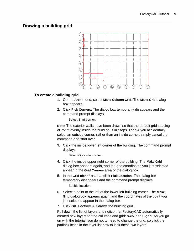
Drawing a building grid
To create a building grid1. On the Arch menu, select Make Column Grid. The Make Grid dialog
box appears.
2. Click Pick Corners. The dialog box temporarily disappears and thecommand prompt displays
Select Start corner:
Note: The exterior walls have been drawn so that the default grid spacingof 75’ fit evenly inside the building. If in Steps 3 and 4 you accidentallyselect an outside corner, rather than an inside corner, simply cancel thecommand and start over.
3. Click the inside lower left corner of the building. The command promptdisplays
Select Opposite corner:
4. Click the inside upper right corner of the building. The Make Griddialog box appears again, and the grid coordinates you just selectedappear in the Grid Corners area of the dialog box.
5. In the Grid Identifier area, click Pick Location. The dialog boxtemporarily disappears and the command prompt displays
Bubble location:
6. Select a point to the left of the lower left building corner. The MakeGrid dialog box appears again, and the coordinates of the point youjust selected appear in the dialog box.
7. Click OK. FactoryCAD draws the building grid.
Pull down the list of layers and notice that FactoryCAD automaticallycreated new layers for the columns and grid: S-col and S-grid. As you goon with the tutorial, you do not to need to change the grid, so click thepadlock icons in the layer list now to lock these two layers.
10 Adding a machine from the block library
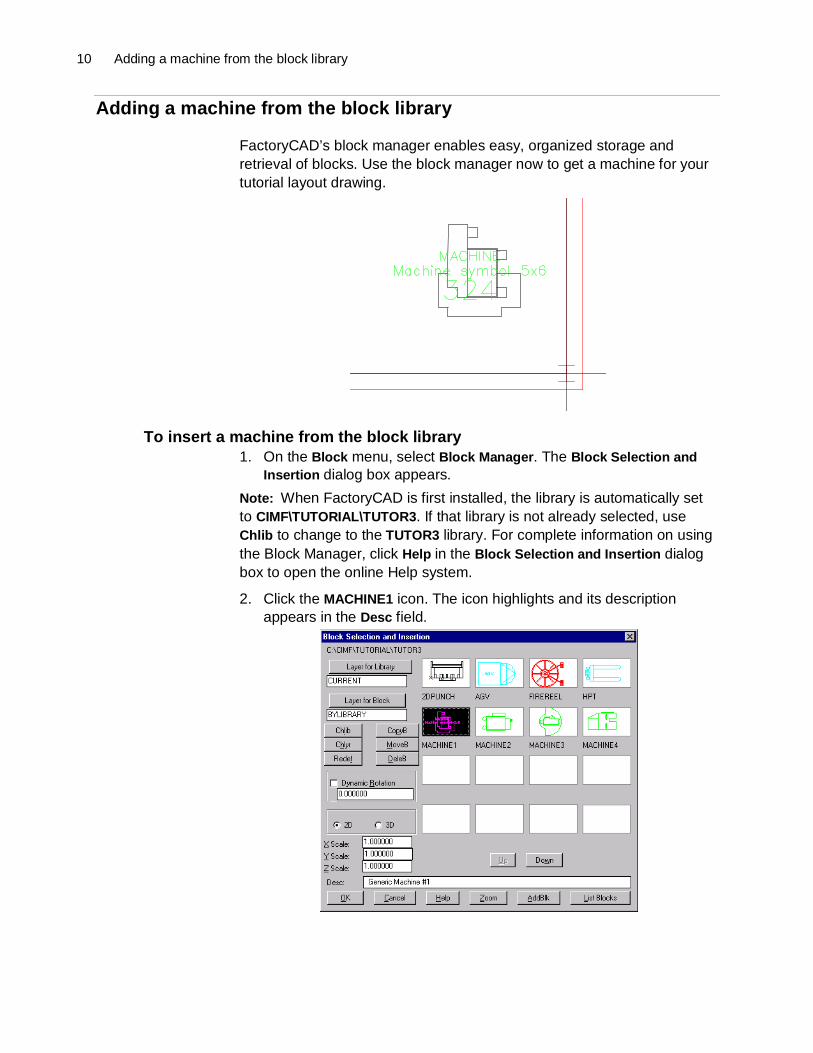
Adding a machine from the block library
FactoryCAD’s block manager enables easy, organized storage andretrieval of blocks. Use the block manager now to get a machine for yourtutorial layout drawing.
To insert a machine from the block library1. On the Block menu, select Block Manager. The Block Selection and
Insertion dialog box appears.
Note: When FactoryCAD is first installed, the library is automatically setto CIMF\TUTORIAL\TUTOR3. If that library is not already selected, useChlib to change to the TUTOR3 library. For complete information on usingthe Block Manager, click Help in the Block Selection and Insertion dialogbox to open the online Help system.
2. Click the MACHINE1 icon. The icon highlights and its descriptionappears in the Desc field.

FactoryCAD Tutorial 11
3. Click OK. The dialog box closes and the command prompt displays
Insertion point:
4. Select a point in the lower right corner of the factory. After you selecta point, the command prompt displays
Enter attribute valuesAsset number:
5. Type a three- or four-digit number, and then press Enter.
If you zoom up to the machine, you’ll see that the asset number youentered appears on the machine, along with the machine description andtype.
Tip: At this point you can pull down the list of layers and see thatFactoryCAD has automatically created three new layers: Machine_desc,Machine_num, and Machine_type. The machine’s text description,number, and type are on the respective layers. Thus, the text visibility canbe controlled by freezing or thawing the corresponding layer.

12 Adding an electrical line
Adding an electrical line
FactoryCAD’s layers dialog box displays a list of standard layers andprovides an easy means of adhering to drawing layer standards for itemssuch as electrical utility lines. The dialog box can be displayed byselecting Set Layer Dialog from the Layer menu. You can also display thelist just before running the respective command by selecting Line,Polyline, Dynamic Text, or Multiline Text from the El/Me, Arch, Ind, or Convmenus.
To draw an electrical line on a standard layer1. If you are not already zoomed to the lower right corner of the building,
zoom in now.
2. On the El/Me menu, select Polyline. The List of Layers dialog boxappears. The Electrical/Mechanical category is already selected.
3. In the Layer Description list, select Power, and then click OK.
When you click OK, the current layer is set to E-pwr and the commandprompt displays the first prompt for the AutoCAD pline command:
From point:
4. Select points to draw an electrical line from the machine to a locationnear building column A9.

FactoryCAD Tutorial 13
You can easily label electrical and mechanical utility lines by selecting alabel from a standard list.
To label an electrical line1. On the El/Me menu, select Electrical Lines. The Electrical Lines dialog
box appears.
2. In the Categories list, click Power. A list of predefined electrical linesappears.
3. Click 240VAC. The 240VAC line highlights.
4. Click OK. The dialog box closes, and the command prompt displays
Select line/polyline or (Draw pline/Change values/Rotate last/Undo last):
5. Select a point near the middle of a relatively long segment of theelectrical line you drew earlier. A text label is inserted into the line.
6. Press Enter to end the command.
14 Adding a disconnect switch
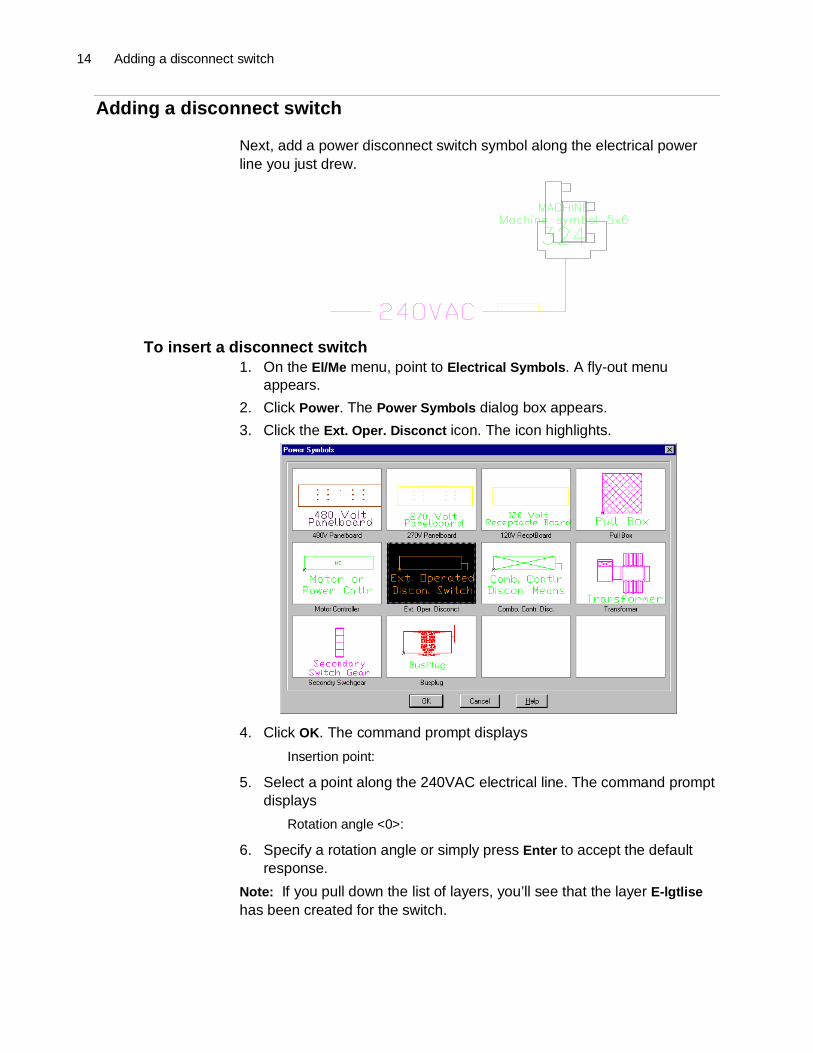
Adding a disconnect switch
Next, add a power disconnect switch symbol along the electrical powerline you just drew.
To insert a disconnect switch1. On the El/Me menu, point to Electrical Symbols. A fly-out menu
appears.
2. Click Power. The Power Symbols dialog box appears.
3. Click the Ext. Oper. Disconct icon. The icon highlights.
4. Click OK. The command prompt displays
Insertion point:
5. Select a point along the 240VAC electrical line. The command promptdisplays
Rotation angle <0>:
6. Specify a rotation angle or simply press Enter to accept the defaultresponse.
Note: If you pull down the list of layers, you’ll see that the layer E-lgtlisehas been created for the switch.
FactoryCAD Tutorial 15
Adding a pit
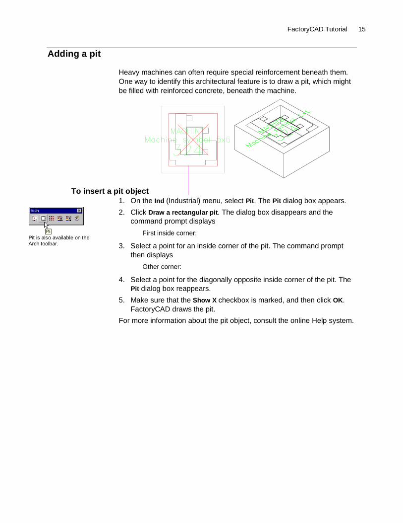
Heavy machines can often require special reinforcement beneath them.One way to identify this architectural feature is to draw a pit, which mightbe filled with reinforced concrete, beneath the machine.
To insert a pit object1. On the Ind (Industrial) menu, select Pit. The Pit dialog box appears.
2. Click Draw a rectangular pit. The dialog box disappears and thecommand prompt displays
First inside corner:
3. Select a point for an inside corner of the pit. The command promptthen displays
Other corner:
4. Select a point for the diagonally opposite inside corner of the pit. ThePit dialog box reappears.
5. Make sure that the Show X checkbox is marked, and then click OK.FactoryCAD draws the pit.
For more information about the pit object, consult the online Help system.
Pit is also available on theArch toolbar.
16 Adding a guardrail
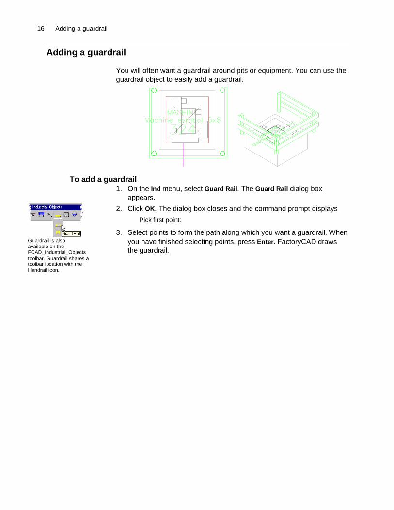
Adding a guardrail
You will often want a guardrail around pits or equipment. You can use theguardrail object to easily add a guardrail.
To add a guardrail1. On the Ind menu, select Guard Rail. The Guard Rail dialog box
appears.
2. Click OK. The dialog box closes and the command prompt displays
Pick first point:
3. Select points to form the path along which you want a guardrail. Whenyou have finished selecting points, press Enter. FactoryCAD drawsthe guardrail.
Guardrail is alsoavailable on theFCAD_Industrial_Objectstoolbar. Guardrail shares atoolbar location with theHandrail icon.

FactoryCAD Tutorial 17
Drawing a floor object
A floor object represents the thickness of the floor, can contain pits, andprovides a helpful frame of reference for rendered drawings.
To draw a floor object1. Zoom so that the whole building is shown in plan view.
2. From the Arch (Architectural) menu, select Floor. The Floors dialogbox appears.
3. Click Draw Floor Boundary. The Floors dialog box disappears and thecommand prompt displays
Select first point:
4. Select an outside corner of the building. The command promptdisplays
Next point:
5. Select the next outside corner. The command prompt displays
Undo/<Next point>:
6. Select the next outside corner. Note that FactoryCAD automaticallycloses the boundary with a diagonal line to the first point. Thecommand prompt displays
Close/ Perpendicular Close/Undo/<Next point>:
7. Select the last outside corner. The boundary line adjusts to form acomplete perimeter of the building. The command prompt displays
Close/ Perpendicular Close/Undo/<Next point>:
8. Press Enter to signal that you have finished drawing the boundary.The Floors dialog box reappears.
9. Click OK. FactoryCAD creates the floor object.
Note: If you pull down the list of layers, you see that a new layer Q-genflrhas been created for the floor. FactoryCAD automatically locks the layerto prevent accidentally selecting and modifying the floor object. To modifya floor object, place the cursor over a floor line and right-click. Options for
Floor is alsoavailable on the Archtoolbar.
18 Adding a container
modifying the floor appear at the command prompt. See the online Helpsystem for details.
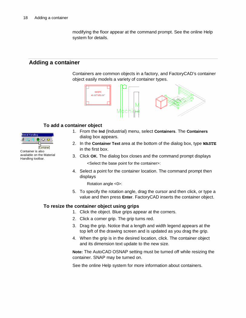
Adding a container
Containers are common objects in a factory, and FactoryCAD’s containerobject easily models a variety of container types.
To add a container object1. From the Ind (Industrial) menu, select Containers. The Containers
dialog box appears.
2. In the Container Text area at the bottom of the dialog box, type WASTEin the first box.
3. Click OK. The dialog box closes and the command prompt displays
<Select the base point for the container>:
4. Select a point for the container location. The command prompt thendisplays
Rotation angle <0>:
5. To specify the rotation angle, drag the cursor and then click, or type avalue and then press Enter. FactoryCAD inserts the container object.
To resize the container object using grips1. Click the object. Blue grips appear at the corners.
2. Click a corner grip. The grip turns red.
3. Drag the grip. Notice that a length and width legend appears at thetop left of the drawing screen and is updated as you drag the grip.
4. When the grip is in the desired location, click. The container objectand its dimension text update to the new size.
Note: The AutoCAD OSNAP setting must be turned off while resizing thecontainer. SNAP may be turned on.
See the online Help system for more information about containers.
Container is alsoavailable on the MaterialHandling toolbar.

FactoryCAD Tutorial 19
Adding a rack
Perhaps one of the most versatile Smart Factory Objects, the rack objectnot only models a variety of rack types, but has been creatively used tomodel roof trusses and other regularly repeating geometry.
To insert a rack object1. From the Ind (Industrial) menu, select Detail Rack. The Racks dialog
box appears.
2. In the Number of Bays Wide(NW) box, enter 2.
3. In the Bay Span(BS) box, enter 60.
4. Click OK. The dialog box closes and the command prompt displays
Rack insertion point >
5. Select a point near grid column A9. The command prompt displays
Rotation angle <0>:
6. Type 90, and then press Enter. FactoryCAD inserts the rack object.
To add another bay using grips1. Click the racks object. Grips appear.
2. Click a grip on the end of the rack. The grip turns red.
3. Drag the grip so it extends at least one bay width from the rack, andthen click. FactoryCAD adds another bay to the rack.
2D and 3D views of rack with added bay, modified shelves in first bay
Shelf heights can be adjusted for each individual bay using the BayParameters tab of the Modify Racks Object dialog box.
Note: When in plan view, you can right-click an object to display a menuthat includes a Modify option. The Modify option displays an object’s
Racks is alsoavailable on the MaterialHandling toolbar.

20 Adding a rack
parameters dialog box. When the view angle is other than plan view, forsome objects the right-click menu is not accessible. Regardless of viewangle, an object’s dialog box can be displayed using the Modify Objectbutton on the toolbar containing the object’s creation icon.
To adjust individual bay parameters1. On the FCAD_Industrial_Objects toolbar, click the Modify Object icon
. The command prompt displays
Select Factory Object to modify:
Note: See page 6 for a description of how to display FactoryCAD toolbars.
2. Click the rack object. The Modify Rack Object dialog box appears.
3. Click the Bays Parameters tab. The Bays Parameters page appears.
4. In the Bay Number box, select the bay you wish to modify.
5. Enter your desired settings for the selected bay.
Tip: Detailed instructions regarding the Bays Parameters tab are in theonline Help system. Click Help in the dialog box to display the relevanttopic.
6. Click OK. FactoryCAD makes the specified changes to the rack.
You can see the effect of shelf height settings by switching to a SW orother 3D view.
FactoryCAD Tutorial 21
Creating a generic tool
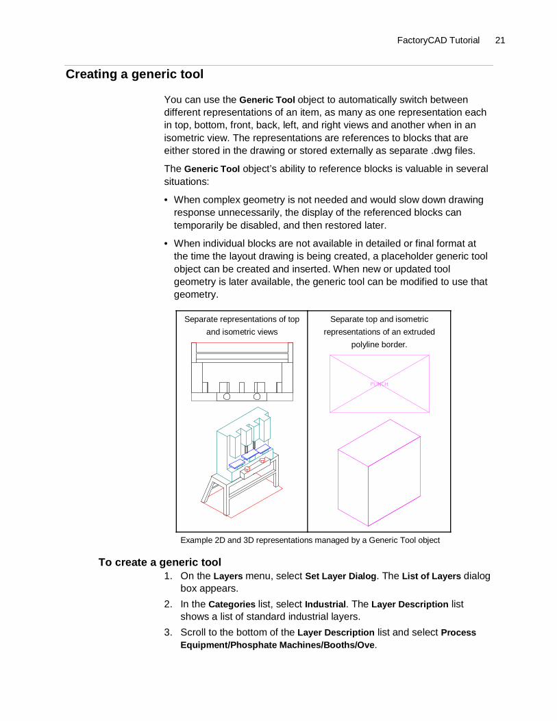
You can use the Generic Tool object to automatically switch betweendifferent representations of an item, as many as one representation eachin top, bottom, front, back, left, and right views and another when in anisometric view. The representations are references to blocks that areeither stored in the drawing or stored externally as separate .dwg files.
The Generic Tool object’s ability to reference blocks is valuable in severalsituations:
• When complex geometry is not needed and would slow down drawingresponse unnecessarily, the display of the referenced blocks cantemporarily be disabled, and then restored later.
• When individual blocks are not available in detailed or final format atthe time the layout drawing is being created, a placeholder generic toolobject can be created and inserted. When new or updated toolgeometry is later available, the generic tool can be modified to use thatgeometry.
Separate representations of top
and isometric views
Separate top and isometric
representations of an extruded
polyline border.
Example 2D and 3D representations managed by a Generic Tool object
To create a generic tool1. On the Layers menu, select Set Layer Dialog. The List of Layers dialog
box appears.
2. In the Categories list, select Industrial. The Layer Description listshows a list of standard industrial layers.
3. Scroll to the bottom of the Layer Description list and select ProcessEquipment/Phosphate Machines/Booths/Ove.

22 Creating a generic tool
Note: If your FactoryCAD is configured to use other than the defaultgeneric layer standards file, your list may be different. In that case, selectan appropriate layer name.
4. Click OK.
5. On the FCAD_Industrial_Objects toolbar, click the Generic Tool icon
. The Generic Tool dialog box appears.
6. In the Tool Name box, type Punch.
7. Click Top File. The 2D Top View Block Name file selection dialog boxappears.
8. Look in the CIMF\Tutorial\Tutor3 folder.
9. Select 2DPUNCH.DWG, and then click Open. The file selection dialogbox closes and the file name 2DPUNCH appears in the Generic Tooldialog box.
10. Click 3D File. The 3D Block Name file selection dialog box appears.
11. Double-click the file 3DPUNCH.dwg. The file selection dialog boxcloses and the file name 3DPUNCH appears in the Generic Tooldialog box.
12. Click the checkboxes for Top View and 3D Block Name so that theycontain a á.
13. Click OK. The dialog box closes and the command prompt displays
Insertion Point
14. Select a point for the tool. FactoryCAD inserts the generic tool object.
At the time of insertion, FactoryCAD determines the smallest rectangularboundary that will enclose the block, and draws that rectangle around the2D block.
To substitute an extruded polyline for referenced blocks1. Select the Punch generic tool object, and then Right-click. A menu
appears.
2. Point to VisFactory. A submenu appears.
3. Select Modify. The Generic Tool dialog box appears.
4. Click the checkboxes for Top View and 3D Block Name so that they areempty.
5. In the Extrusion Depth box, type 60.
6. Click OK. The dialog box closes and the punch generic tool objectnow appears using a representation of the extruded polyline border,rather than the referenced blocks.

FactoryCAD Tutorial 23
Adding a safety fence
Safety fence around tools is a common requirement. You can use thesafety fence object to easily create a range of safety fence configurations,including a variety of door options.
To create a safety fence1. On the Ind (Industrial) menu, point to Safety Fence. A sub-menu
appears.
2. Select Safety Fence.... The Safety Fence dialog box appears.
3. Click OK. The dialog box closes and the command prompt displays
Select first point:
4. Select points to form a path along which you want a safety fence.When you have finished selecting points, press Enter. FactoryCADdraws the safety fence.
To add a door to a safety fence1. Select the safety fence, and then right-click. The safety fence right-
click menu appears.
2. Point to VisFactory. A submenu appears.
3. Select Add Door. The Add Safety Fence Door dialog box appears.
4. From the Door Style drop-down list, select Sliding Door.
5. Click OK. The dialog box closes and the command prompt displays
Select safety fence and location:
6. Select a point on the safety fence. A door symbol appears on theselected safety fence.
7. Drag the door symbol around the fence until it is in the desiredposition, and then click. FactoryCAD draws the door and promptsagain
Select safety fence and location:
8. Press Enter to end the door insertion routine.
The side of the safety fence the sliding door is initially on depends onwhich direction you went when you drew the safety fence. The door caneasily be moved to the other side via grips.

24 Adding a safety fence
To change the fence side of a sliding safety fence door1. Click the door. Three grips appear along the door opening and one on
the door.
2. Click the grip on the door. The grip turns red.
3. Drag the crosshairs to the other side of the safety fence, and thenrelease the mouse button. FactoryCAD moves the door to the otherside of the fence.

FactoryCAD Tutorial 25
Adding a mezzanine
FactoryCAD’s mezzanine object can model an infinite variety ofmezzanine constructions. You can use the following steps to create arectangular mezzanine.
To insert a rectangular mezzanine1. Zoom to display a plan view of the area in which you want to insert the
mezzanine.
2. On the FCAD_Industrial_Objects toolbar, click the mezzanine icon .The Mezzanine dialog box appears.
3. In the Mezzanine Outline area, select Draw New Rectangle.
4. Click OK. The dialog box closes and command prompt displays
Select First Corner
5. Select a location for the first corner of the mezzanine. The commandprompt displays
Select Opposite Corner
6. Select the diagonally opposite corner of the mezzanine. FactoryCADdraws the mezzanine.

26 Modifying a mezzanine
Modifying a mezzanine
Mezzanines are highly customizable, ready for you to add stairs, ramps,and ladders; create holes; join with other mezzanines; create gaps inrailing; cut out sections; and more.
The following mezzanine example has a section cut out to make room forstairs. Similar mezzanine shapes could have been achieved by adding asecond mezzanine object, then joining the two mezzanines into oneobject.
To find a description of how to cut out a section of a mezzanine1. Start the FactoryCAD online Help system.
• On the Factory menu, point to Factory Layout Software Help. A sub-menu appears. Select FactoryCAD. The FactoryCAD online Helpsystem appears.
-or-
• In a FactoryCAD dialog box with a help button, such as theMezzanine dialog box, click Help. The FactoryCAD online Helpsystem window appears, opened to a topic related to the dialogbox.
2. In the navigation pane at the left of the Help window, click Search. TheSearch tab appears.
3. In the Type in the keyword to find box, type mezzanine.
4. Click List Topics. A list of topics containing the word mezzanineappears in the Select Topic to display area.
5. In the list of topics, double-click Cutting a mezzanine section. The topicTo cut a mezzanine section appears.
Note: You could also reach the To cut a mezzanine section topic byfollowing links from within the main mezzanine topic.

FactoryCAD Tutorial 27
To add stairs to a mezzanine1. In plan view, select a mezzanine object and right-click. The
mezzanine right-click menu appears.
2. Point to VisFactory. A submenu appears.
3. Click Add Stairs. The Stairway dialog box appears.
4. Click OK. The dialog box closes and a stair icon appears attached tothe mezzanine. The command prompt displays
Connect <select insert point>
5. Move the stairs to your desired location. As long as you stay near themezzanine edge, the stairs snap to the edge of the mezzanine.
6. When the stairs are in the desired position, click the left mouse button.FactoryCAD draws the stairs.
Note: The stairs object will not draw stairs that exceed the maximumchange in elevation allowed by OSHA for a single flight of stairs. If agreater change in elevation is needed, add a landing at the end of thestairs object, and then add another set of stairs.
To add a landing to a stairs object1. In plan view, select a stairs object, and then right-click. The stairs
right-click menu appears.
2. Point to VisFactory. A submenu appears.
3. Click Add Landing. The right-click menu disappears and a landingobject appears at the pointer location.
4. Move the landing to your desired location. When you are near theconnector at the end of a stairs object, the landing snaps into place.
5. When the landing is in the desired position, click the left mousebutton. FactoryCAD draws the landing.
To add stairs to a landingFollow the same procedure as for adding stairs to a mezzanine. Note thatyou can have FactoryCAD automatically adjust the stairs to meet aspecific height by entering a value in the Ending Elevation box of thestairway dialog box.
28 Appendix A — Movie files
Appendix A — Movie files
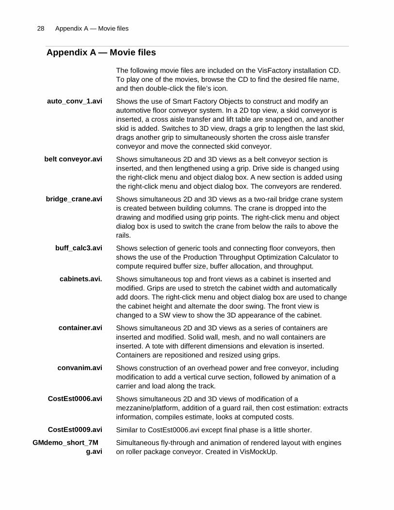
The following movie files are included on the VisFactory installation CD.To play one of the movies, browse the CD to find the desired file name,and then double-click the file’s icon.
Shows the use of Smart Factory Objects to construct and modify anautomotive floor conveyor system. In a 2D top view, a skid conveyor isinserted, a cross aisle transfer and lift table are snapped on, and anotherskid is added. Switches to 3D view, drags a grip to lengthen the last skid,drags another grip to simultaneously shorten the cross aisle transferconveyor and move the connected skid conveyor.
Shows simultaneous 2D and 3D views as a belt conveyor section isinserted, and then lengthened using a grip. Drive side is changed usingthe right-click menu and object dialog box. A new section is added usingthe right-click menu and object dialog box. The conveyors are rendered.
Shows simultaneous 2D and 3D views as a two-rail bridge crane systemis created between building columns. The crane is dropped into thedrawing and modified using grip points. The right-click menu and objectdialog box is used to switch the crane from below the rails to above therails.
Shows selection of generic tools and connecting floor conveyors, thenshows the use of the Production Throughput Optimization Calculator tocompute required buffer size, buffer allocation, and throughput.
Shows simultaneous top and front views as a cabinet is inserted andmodified. Grips are used to stretch the cabinet width and automaticallyadd doors. The right-click menu and object dialog box are used to changethe cabinet height and alternate the door swing. The front view ischanged to a SW view to show the 3D appearance of the cabinet.
Shows simultaneous 2D and 3D views as a series of containers areinserted and modified. Solid wall, mesh, and no wall containers areinserted. A tote with different dimensions and elevation is inserted.Containers are repositioned and resized using grips.
Shows construction of an overhead power and free conveyor, includingmodification to add a vertical curve section, followed by animation of acarrier and load along the track.
Shows simultaneous 2D and 3D views of modification of amezzanine/platform, addition of a guard rail, then cost estimation: extractsinformation, compiles estimate, looks at computed costs.
Similar to CostEst0006.avi except final phase is a little shorter.
Simultaneous fly-through and animation of rendered layout with engineson roller package conveyor. Created in VisMockUp.
auto_conv_1.avi
belt conveyor.avi
bridge_crane.avi
buff_calc3.avi
cabinets.avi.
container.avi
convanim.avi
CostEst0006.avi
CostEst0009.avi
GMdemo_short_7Mg.avi

FactoryCAD Tutorial 29
Shows simultaneous 2D and 3D views as a gravity roller conveyorstraight section is dropped in, then lengthened using grips. Note theautomatic addition of standard length sections. Adds a curve sectionusing the right-click menu and object dialog box. Adds a new straightsection with Wheel Rollers option; renders the conveyors to show renderview.
Shows simultaneous 2D and 3D views of the creation of a guard rail,modifies the length by dragging a grip, modifies rail type (2 rails to 3 rails)using the right-click menu and object dialog box.
Shows simultaneous 2D and 3D views of creation of jib crane,modification of jib length and swing arc by dragging a grip.
Shows 2D creation of a rectangular mezzanine, cut-out of a section, andaddition of stairs. Switches to 3D view, adds landing and stairs. Modifiesbottom stairs to extend to floor level.
Shows simultaneous 2D and 3D views of the creation of an overheadpower and free conveyor, including vertical curve and addition of biasbank section.
Shows 2D creation of dual-sided platform and modification of one sideusing grips. Switches to 3D view, uses the right-click menu and objectdialog box to show railing. Note that by design, the inside platform edgedoes not have a railing.
Shows simultaneous top and front views as a rack is created. Showsmodification of shelf height in one bay of a rack using the right-click menuand object dialog box. Switches front view to SW view to show 3D rack.
Shows simultaneous 2D and 3D views of creation of safety fence arounda tool. Modifies fence using grips. Uses right-click menu and door dialogbox to add a door. Uses right-click menu and object dialog box to changethe fence pattern.
Shows simultaneous 2D and 3D views of the creation of v-belt live rollerconveyor sections. Initial straight segment length is modified using grips.Display of a motor is added using the right-click menu and object dialogbox. A new curved segment is added using the right-click menu andobject dialog box. The curve section is dragged to a new location, and anew straight section is automatically added to lengthen the systemaccordingly. The views are then rendered.
grc.avi
guardrail.avi
jib_crane.avi
mezzanine.avi
overhead.avi
platform.avi
racks.avi
safety_fence.avi
vblr conveyor.avi
30 Index
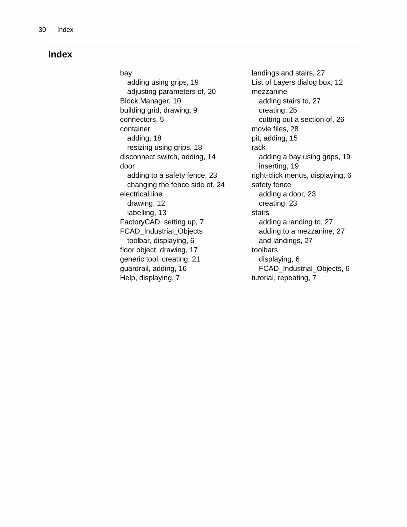
Index
bayadding using grips, 19adjusting parameters of, 20
Block Manager, 10building grid, drawing, 9connectors, 5container
adding, 18resizing using grips, 18
disconnect switch, adding, 14door
adding to a safety fence, 23changing the fence side of, 24
electrical linedrawing, 12labelling, 13
FactoryCAD, setting up, 7FCAD_Industrial_Objects
toolbar, displaying, 6floor object, drawing, 17generic tool, creating, 21guardrail, adding, 16Help, displaying, 7
landings and stairs, 27List of Layers dialog box, 12mezzanine
adding stairs to, 27creating, 25cutting out a section of, 26
movie files, 28pit, adding, 15rack
adding a bay using grips, 19inserting, 19
right-click menus, displaying, 6safety fence
adding a door, 23creating, 23
stairsadding a landing to, 27adding to a mezzanine, 27and landings, 27
toolbarsdisplaying, 6FCAD_Industrial_Objects, 6
tutorial, repeating, 7