Factory-Made, Wrought Steel, Buttwelding Induction Bends ...
22
Factory-Made, Wrought Steel, Buttwelding Induction Bends for Transportation and Distribution Systems AN AMERICAN NATIONAL STANDARD ASME B16.49-2007 (Revision of ASME B16.49-2000) Copyright 2008 by the American Society of Mechanical Engineers. No reproduction may be made of this material without written consent of ASME. c
Transcript of Factory-Made, Wrought Steel, Buttwelding Induction Bends ...

Factory-Made, Wrought Steel, Buttwelding Induction Bends for Transportation and Distribution Systems
A N A M E R I C A N N A T I O N A L S T A N D A R D
ASME B16.49-2007(Revision of ASME B16.49-2000)
Copyright 2008 by the American Society of Mechanical Engineers.No reproduction may be made of this material without written consent of ASME.
c

CONTENTS
Foreword . . . . . . . . . . . . . . . . . . . . . . . . . . . . . . . . . . . . . . . . . . . . . . . . . . . . . . . . . . . . . . . . . . . . . . . . . . . . . . ivCommittee Roster . . . . . . . . . . . . . . . . . . . . . . . . . . . . . . . . . . . . . . . . . . . . . . . . . . . . . . . . . . . . . . . . . . . . . vCorrespondence With the B16 Committee . . . . . . . . . . . . . . . . . . . . . . . . . . . . . . . . . . . . . . . . . . . . . . vi
1 Scope and Definitions . . . . . . . . . . . . . . . . . . . . . . . . . . . . . . . . . . . . . . . . . . . . . . . . . . . . . . . . . . . 1
2 Pressure Ratings . . . . . . . . . . . . . . . . . . . . . . . . . . . . . . . . . . . . . . . . . . . . . . . . . . . . . . . . . . . . . . . . 2
3 Size . . . . . . . . . . . . . . . . . . . . . . . . . . . . . . . . . . . . . . . . . . . . . . . . . . . . . . . . . . . . . . . . . . . . . . . . . . . . 2
4 Marking . . . . . . . . . . . . . . . . . . . . . . . . . . . . . . . . . . . . . . . . . . . . . . . . . . . . . . . . . . . . . . . . . . . . . . . . 2
5 Material . . . . . . . . . . . . . . . . . . . . . . . . . . . . . . . . . . . . . . . . . . . . . . . . . . . . . . . . . . . . . . . . . . . . . . . . 4
6 Material for Bends Containing Welds . . . . . . . . . . . . . . . . . . . . . . . . . . . . . . . . . . . . . . . . . . . . . 4
7 Chemical Composition . . . . . . . . . . . . . . . . . . . . . . . . . . . . . . . . . . . . . . . . . . . . . . . . . . . . . . . . . . . 5
8 Material Properties . . . . . . . . . . . . . . . . . . . . . . . . . . . . . . . . . . . . . . . . . . . . . . . . . . . . . . . . . . . . . . 5
9 Heat Treatment. . . . . . . . . . . . . . . . . . . . . . . . . . . . . . . . . . . . . . . . . . . . . . . . . . . . . . . . . . . . . . . . . . 8
10 Qualification Bend. . . . . . . . . . . . . . . . . . . . . . . . . . . . . . . . . . . . . . . . . . . . . . . . . . . . . . . . . . . . . . . 8
11 Test Requirements. . . . . . . . . . . . . . . . . . . . . . . . . . . . . . . . . . . . . . . . . . . . . . . . . . . . . . . . . . . . . . . 8
12 Dimensional Requirements . . . . . . . . . . . . . . . . . . . . . . . . . . . . . . . . . . . . . . . . . . . . . . . . . . . . . . . 9
13 Inspection of Production Bends . . . . . . . . . . . . . . . . . . . . . . . . . . . . . . . . . . . . . . . . . . . . . . . . . . 10
14 Certification . . . . . . . . . . . . . . . . . . . . . . . . . . . . . . . . . . . . . . . . . . . . . . . . . . . . . . . . . . . . . . . . . . . . . 10
SR15 Supplementary Requirements . . . . . . . . . . . . . . . . . . . . . . . . . . . . . . . . . . . . . . . . . . . . . . . . . . . . 10
Figures1 Bend Dimensional Terms . . . . . . . . . . . . . . . . . . . . . . . . . . . . . . . . . . . . . . . . . . . . . . . . . . . . . . . 32 Test Specimen Locations and Orientations — Longitudinal Seam . . . . . . . . . . . . . . . . 63 Test Specimen Locations and Orientations — Helical Seam . . . . . . . . . . . . . . . . . . . . . . 74 Measurement of Bend Angle and Out-of-Squareness . . . . . . . . . . . . . . . . . . . . . . . . . . . . 11
Tables1 Tensile Properties . . . . . . . . . . . . . . . . . . . . . . . . . . . . . . . . . . . . . . . . . . . . . . . . . . . . . . . . . . . . . . 42 Maximum Limits of Chemical Elements That May Be Used . . . . . . . . . . . . . . . . . . . . . 43 Limits on Essential Variables . . . . . . . . . . . . . . . . . . . . . . . . . . . . . . . . . . . . . . . . . . . . . . . . . . . 8
Mandatory AppendixI References . . . . . . . . . . . . . . . . . . . . . . . . . . . . . . . . . . . . . . . . . . . . . . . . . . . . . . . . . . . . . . . . . . . . . 13
Nonmandatory AppendicesA Quality System Program . . . . . . . . . . . . . . . . . . . . . . . . . . . . . . . . . . . . . . . . . . . . . . . . . . . . . . . 14B Induction Bend Data Sheet . . . . . . . . . . . . . . . . . . . . . . . . . . . . . . . . . . . . . . . . . . . . . . . . . . . . . 15
iii
Copyright 2008 by the American Society of Mechanical Engineers.No reproduction may be made of this material without written consent of ASME.
c

FOREWORD
In 1993, members of the ASME B31.8 Code for Pressure Piping Gas — Transmission andDistribution Systems committee approached the B16 committee to develop a standard that coverspipeline bends produced by the induction bending process.
Subcommittee F reviewed the request and identified that no current specification covered thisproduct to the satisfaction of the users. It was also determined that this Standard would needto be more performance based than most other B16 standards, which are normally productstandards with set dimensional requirements.
At the 1994 meeting of Subcommittee F, the project to develop a standard was accepted.Through the cooperation of producers and users familiar with the process, and with approvalby the Standards Committee and ASME, ASME B16.49-2000 received approval as an AmericanNational Standard on April 25, 2000.
In 2005, the committee undertook a general review of this document. Based on the usage ofthis Standard over the last 5 years, a number of revisions, clarifications, and additions weredetermined to be needed to make the document more user friendly. Some requirements havebeen dropped, revised, and clarified to reflect the desires of the users and manufacturers. Thereference data has been updated and the interpretation section has been removed from theStandard. These revisions were incorporated into this B16.49-2007 edition.
This revision was approved by the American National Standards Institute on October 12, 2007.
iv
Copyright 2008 by the American Society of Mechanical Engineers.No reproduction may be made of this material without written consent of ASME.
c

ASME B16 COMMITTEEStandardization of Valves, Flanges, Fittings, and Gaskets
(The following is the roster of the Committee at the time of approval of this Standard.)
STANDARDS COMMITTEE OFFICERS
W. B. Bedesem, ChairM. L. Nayyar, Vice Chair
U. D’Urso, Secretary
STANDARDS COMMITTEE PERSONNEL
R. W. Barnes, ANRIC Enterprises, Inc.W. B. Bedesem, ExxonMobil Research and Engineering Co.D. F. Buccicone, Elkhart Products Corp.M. A. Clark, NIBCO, Inc.U. D’Urso, The American Society of Mechanical EngineersC. E. Floren, Mueller Co.D. R. Frikken, Becht Engineering Co.M. L. Henderson, ConsultantG. A. Jolly, Vogt Valves/Flowserve Corp.
SUBCOMMITTEE F — STEEL THREADED AND WELDING FITTINGS
G. A. Jolly, Chair, Vogt Valves/Flowserve Corp.G. A. Cuccio, Vice Chair, Capitol Manufacturing Co.T. Lazar, Secretary, The American Society of Mechanical EngineersA. Appleton, Alloy Stainless Products Co., Inc.W. J. Birkholz, Markovitz Enterprises, Inc.K. W. Doughty, Shaw Alloy Piping Products, Inc.J. P. Ellenberger, ConsultantD. R. Frikken, Becht Engineering Co.
v
M. Katcher, Haynes InternationalW. N. McLean, Newco ValvesT. A. McMahon, Fisher Controls International, Inc.M. L. Nayyar, Bechtel Corp.J. D. Page, U.S. Nuclear Regulatory CommissionW. H. Patrick, The Dow Chemical Co.R. A. Schmidt, Hackney Ladish, Inc.H. R. Sonderegger, Anvil International, Inc.W. M. Stephan, Flexitallic, L.P.D. A. Williams, Southern Company Generation
R. E. Johnson, ConsultantC. J. Lafferty, Pennsylvania Machine Works, Inc.D. H. Monroe, ConsultantR. A. Schmidt, Hackney Ladish, Inc.H. R. Sonderegger, Anvil International, Inc.J. P. Tucker, Flowserve Corp.M. M. Zaidi, Jacobs Engineering Group, Inc.
Copyright 2008 by the American Society of Mechanical Engineers.No reproduction may be made of this material without written consent of ASME.
c

CORRESPONDENCE WITH THE B16 COMMITTEE
General. ASME Standards are developed and maintained with the intent to represent theconsensus of concerned interests. As such, users of this Standard may interact with the Committeeby requesting interpretations, proposing revisions, and attending Committee meetings. Corre-spondence should be addressed to:
Secretary, B16 Standards CommitteeThe American Society of Mechanical EngineersThree Park AvenueNew York, NY 10016-5990
As an alternative, inquiries may be submitted via e-mail to: [email protected] Revisions. Revisions are made periodically to the Standard to incorporate changes
that appear necessary or desirable, as demonstrated by the experience gained from the applicationof the Standard. Approved revisions will be published periodically.
The Committee welcomes proposals for revisions to this Standard. Such proposals should beas specific as possible, citing the paragraph number(s), the proposed wording, and a detaileddescription of the reasons for the proposal, including any pertinent documentation.
Interpretations. Upon request, the B16 Committee will render an interpretation of any require-ment of the Standard. Interpretations can only be rendered in response to a written request sentto the Secretary of the B16 Standards Committee.
The request for interpretation should be clear and unambiguous. It is further recommendedthat the inquirer submit his/her request in the following format:
Subject: Cite the applicable paragraph number(s) and the topic of the inquiry.Edition: Cite the applicable edition of the Standard for which the interpretation is
being requested.Question: Phrase the question as a request for an interpretation of a specific requirement
suitable for general understanding and use, not as a request for an approvalof a proprietary design or situation. The inquirer may also include any plansor drawings, which are necessary to explain the question; however, theyshould not contain proprietary names or information.
Requests that are not in this format will be rewritten in this format by the Committee priorto being answered, which may inadvertently change the intent of the original request.
ASME procedures provide for reconsideration of any interpretation when or if additionalinformation that might affect an interpretation is available. Further, persons aggrieved by aninterpretation may appeal to the cognizant ASME Committee or Subcommittee. ASME does not“approve,” “certify,” “rate,” or “endorse” any item, construction, proprietary device, or activity.
Attending Committee Meetings. The B16 Standards Committee regularly holds meetings, whichare open to the public. Persons wishing to attend any meeting should contact the Secretary ofthe B16 Standards Committee.
vi
Copyright 2008 by the American Society of Mechanical Engineers.No reproduction may be made of this material without written consent of ASME.
c

ASME B16.49-2007
FACTORY-MADE, WROUGHT STEEL, BUTTWELDINGINDUCTION BENDS FOR TRANSPORTATION AND
DISTRIBUTION SYSTEMS
1 SCOPE AND DEFINITIONS
1.1 General
This Standard covers design, material, manufacturing,testing, marking, and inspection requirements forfactory-made pipeline bends of carbon steel materialshaving controlled chemistry and mechanical properties,produced by the induction bending process, with orwithout tangents. This Standard covers induction bendsfor transportation and distribution piping applications(e.g., ASME B31.4, B31.8, and B31.11). Process and powerpiping have differing requirements and materials thatmay not be appropriate for the restrictions and examina-tions described herein and, therefore, are not includedin this Standard.
1.2 Manufacturing Process
This process utilizes induction heating to heat a nar-row band 360 deg around a pipe or cylinder at thepoint of bending as the pipe or cylinder is being pushedthrough the inductor coil at a constant velocity. Afterthe material passes through the coil, it may be cooledby forced air or water spray, or it may be allowed tocool in still air. Bends in any producible wall thicknessand diameter are covered. Induction bends covered bythis Standard may be produced from seamless pipe,welded pipe, or cylinders.
1.3 Fabricated Bends
Larger angle bends obtained by girth welding two ormore smaller angle bends together are considered pipefabrications and as such are not within the scope of thisStandard.
1.4 Standard Units
The values stated in either metric units or U.S. Cus-tomary units are to be regarded separately as standard.Within the text, Customary values are shown in paren-theses. The values stated in each system are not exactequivalents; therefore, each system must be used inde-pendently of the other. Combining values from two sys-tems may result in nonconformance with the standard.
1.5 References
Standards and specifications adopted by reference inthis Standard are shown in Mandatory Appendix I. It
1
is not practical to identify the specific edition of eachstandard and specification in the individual references.Instead, the specific edition reference is identified inMandatory Appendix I. A product made in conformancewith a prior edition of reference standards and in allother respects conforming to this Standard will be con-sidered to be in compliance.
1.6 Codes and Regulations
A bend used under the jurisdiction of a referencingcode or governmental regulation is subject to any limita-tion of that code or regulation. This includes any maxi-mum temperature limitation or rule governing the useof a material at low temperature.
1.7 Service Conditions
Criteria for selection of bend material for a particularfluid service are not within the scope of this Standard.
1.8 Convention
In conformance with this Standard, the conventionfor fixing significant digits where limits, maximum andminimum values, are specified shall be “rounded off”as defined in ASTM Practice E 29. This requires that anobserved or calculated value shall be rounded off tothe nearest unit in the last right-hand digit used forexpressing the limit. Decimal values and tolerance donot imply a particular method of measurement.
1.9 Quality Systems
Requirements relating to the manufacturers’ qualitysystem programs are described in NonmandatoryAppendix A.
1.10 Glossary
bend qualification procedure: a document that specifies theproperties of the starting pipe; the equipment to be used;the bending parameters; the qualification bend testresults; and the postbend, heat-treat equipment andcycle used for the manufacture of the bends. If nonde-structive testing of the bend is required, procedures thathave not been approved previously shall be submitted.
cylinder: a joint of pipe produced by a rolling and weldingplate, as opposed to a joint of pipe produced in accor-dance with a recognized specification.
Copyright 2008 by the American Society of Mechanical Engineers.No reproduction may be made of this material without written consent of ASME.
c

ASME B16.49-2007
extrados: the outside arc of the bend.
intrados: the inside arc of the bend.
minimum (design) wall thickness: the wall thickness speci-fied or computed in accordance with the piping codeas the minimum acceptable for the temperature andpressure application.
nominal (design) wall thickness: the wall thickness speci-fied on the order or marked on the bend.
ovality, %: [(O.D. max. − O.D. min.)/(O.D. nom)] � 100where O.D. is a linear measurement of the maximum,minimum, or nominal outside diameter.
qualification bend: a bend segment that is produced andtested and is used to qualify the bending procedure.
transition zone: the area, at the tangent points of a bend,that covers the change (transition) from unheated toheated material.
NOTE: The terms “bender” and “manufacturer” are used inter-changeably in this Standard.
1.11 Ordering Information
The purchaser shall be responsible to specify all theordering information necessary to purchase the neededbends. Examples of such information include, but arenot limited to, the following:
(a) quantity(b) description of bend and nominal dimensions (i.e.,
size, bend radius, wall thickness, bend angle, tangentlengths, etc.)
(c) steel composition by grade(d) seamless or welded(e) specification number (including year)(f) supplementary requirements from section SR15(g) additional requirementsNonmandatory Appendix B is provided as one possi-
ble guideline for providing the required information.
2 PRESSURE RATINGS
2.1 Basis of Ratings
The allowable internal pressure rating for bendsdesigned in accordance with this Standard shall not beless than that which is calculated for straight seamlesspipe (or for pipe welded with a joint efficiency factor of1.0) of equivalent material (as shown by comparison ofcomposition and mechanical properties in the respectivematerial specifications) in accordance with the rulesestablished in the applicable sections of the referencingcode for pressure piping. For these calculations, applica-ble data for the nominal size, nominal wall thickness,and material equivalent to that of the bend materialshall be used. Nominal size, nominal wall thickness, andmaterial identity markings on the bend may be used inlieu of pressure-rating markings.
2
2.2 Design of Bends
The required internal pressure design thickness at theintrados (inside radius) of the bend shall be determinedin accordance with eq. (1) of this Standard. The thicknessat the neutral axis (see Fig. 1) and on the extrados (outerradius) of the bend shall be no less than the mating pipedesign thickness or the customer-specified minimumwall thickness.
TI ≥ � 4�R/Do� − 14�R/Do� − 2 �t (1)
whereDo p nominal outside diameterR p bend centerline radiusTI p minimum required thickness at the intrados
t p nominal design wall thickness (see para. 2.1)
3 SIZE
The diameter of bends shall be identified by the nomi-nal pipe size (NPS) as defined in ASME B36.10M (e.g.,NPS 24). Alternatively or in addition, the marking mayinclude the nominal size as defined in ISO 6708, whichconsists of the letters “DN” followed by a dimensionlesswhole number, which is indirectly related to the physicalsize, in millimeters, of the outside diameter of pipe towhich the bend is intended to be welded (e.g., DN 600).
4 MARKING
4.1 Standard Marking
Each bend shall be marked on the outside surfacewithin 300 mm (12 in.) of one end to show the following:
(a) manufacturer’s name or trademark(b) heat number or manufacturer’s heat identification(c) material grade symbol (see para. 11.3 and Table 1)(d) B16.49(e) nominal pipe size (NPS)(f) nominal wall thickness(g) bend radius(h) bend angle(i) postbending, heat-treatment condition (see
para. 9.3)(j) supplementary requirements (if applicable) (see
section SR15)Marking may be in any consistent units (metric or
customary) but care shall be taken to avoid confusion.Use “X” and grade in lieu of “P” and grade for materialdesignation for the customary stamping option.
When specified by the purchaser, each bend shall bepaint stenciled with the same information in 25 mm(1 in.) or larger letters on the inside surface within150 mm (6 in.) of each end, except for NPS 12 (DN 300)or smaller, which only requires outside surface marking.Marking materials shall not adversely affect the bendor coating.
Copyright 2008 by the American Society of Mechanical Engineers.No reproduction may be made of this material without written consent of ASME.
c

ASME B16.49-2007
Fig. 1 Bend Dimensional Terms
Tangent length
Chord
Intrados
Extrados
Do
I.D.
Centerline radius, R
Tangent point/transition area
Tangent point/transition area
Neu
tral
axi
s
Arc
Wall thickness Wall thickness
Tangent length
90 deg of bend
3
Copyright 2008 by the American Society of Mechanical Engineers.No reproduction may be made of this material without written consent of ASME.
c

ASME B16.49-2007
Table 1 Tensile Properties
Tensile Properties Hardness
Grade and Minimum Yield Minimum Tensile Minimum Maximum HB Maximum HRCSymbol Strength, MPa (ksi) Strength, MPa (ksi) Elongation, % [Note (1)] [Note (2)]
P241 (X241) 241 (35) 414 (60) 20 238 22P290 (X290) 290 (42) 414 (60) 20 238 22P317 (X317) 317 (46) 434 (63) 20 238 22P359 (X359) 359 (52) 455 (66) 20 238 22P386 (X386) 386 (56) 490 (71) 20 238 22P414 (X414) 414 (60) 517 (75) 20 238 22P448 (X448) 448 (65) 531 (77) 18 238 22P483 (X483) 483 (70) 565 (82) 16 247 24P552 (X552) 552 (80) 621 (90) 16 247 24
GENERAL NOTE: Intermediate grades may be purchased subject to agreement between the purchaser and manufacturer.
NOTES:(1) HB (Hardness Brinell) is the primary number.(2) HRC (Hardness Rockwell C) is an approximation based on ASTM E 140 hardness conversion.
4.2 Depth of Stamping
Where steel stamps are used, care shall be taken sothat the stamping is not so deep or so sharp as to causecracking, or to reduce the wall thickness of the bendbelow the minimum allowed.
4.3 Compliance
Marking B16.49 on the bend designates that the bendwas manufactured in conformance with ASME B16.49.Adding the prefix “ASME” is optional.
5 MATERIAL
5.1 Starting Materials
Bends covered by this Standard shall be producedfrom carbon steel pipe or cylinders having a chemistryin conformance with Table 2. Pipe may be furnished bythe purchaser or supplied by the manufacturer. Startingpipe shall be seamless, submerged arc welded (SAW),or electric resistance welded. Helically welded pipe isallowed, provided the more stringent testing require-ments of subpara. 11.1.3(b) are met. Starting materialshall be free from low-melting temperature metals,cracks, nicks, gouges, waves, buckles, or other such sur-face contamination defects that may inhibit successfulcompletion of a bend.
5.1.1 Contamination. Contamination of pipe sur-faces before or during bending by low-melting tempera-ture metals (i.e., copper, brass, zinc/galvanized,aluminum, etc.) can have serious effects on the bendingprocess and the finished bend properties. Contact withsuch metals shall not be allowed.
5.1.2 Surface Condition. Prior to bending, materialGrades P359 (X359) and higher shall be grit blasted toa commercial finish (SSPC SP-6) as a minimum on thosesections to be bent.
4
Table 2 Maximum Limits of Chemical ElementsThat May Be Used
Element Symbol Maximum, %
Carbon C 0.30Manganese Mn 1.60 [Note (1)]Phosphorus P 0.025Sulfur S 0.015Silicon Si 0.50Chromium Cr 0.30Molybdenum Mo 0.25Vanadium V 0.10Copper Cu 0.50Nickel Ni 1.00Niobium Nb (Cb) 0.10
GENERAL NOTE: The chemical requirements of this Table are notintended to represent the composition of any heat of steel, but torecord the maximum permissible amounts of individual elements.
NOTE:(1) For Grades P483 (X483) and higher for each reduction of
0.01% below the specified maximum carbon content, anincrease of 0.05% above the maximum manganese content ispermissible, up to a maximum of 2.00%.
6 MATERIAL FOR BENDS CONTAINING WELDS
6.1 Longitudinal Weld Seams
6.1.1 Seam welds in pipe made to an API, ASTM,or CSA specification must meet welding and nonde-structive examination (NDE) requirements of that speci-fication.
6.1.2 Other pipe or cylinders, not manufacturedto the above specifications, shall be made by welders,welding operators, and welding procedures qualifiedunder the provisions of Section IX of the ASME Boilerand Pressure Vessel Code (BPVC). Before bending, 100%of each weld seam shall be radiographed in accordance
Copyright 2008 by the American Society of Mechanical Engineers.No reproduction may be made of this material without written consent of ASME.
c

ASME B16.49-2007
with ASME Section VIII, Division 1, para. UW-51, andshall meet the acceptance criteria specified therein.
In place of radiographic examination, welds may beultrasonically examined in accordance with Appendix12 of ASME Section VIII, Division 1.
6.1.3 The longitudinal weld seam should belocated on the neutral axis (� p 0 deg or 180 deg inFig. 1). When this is not possible, the weld seam shallbe located not more than 15 deg from the neutral axis.Helically welded pipe is an exception to this weld loca-tion requirement.
6.2 Girth Welds
Bending through a girth weld shall not be allowedunless agreed upon between the purchaser and manu-facturer.
7 CHEMICAL COMPOSITION
The chemical composition of each heat1 of materialfurnished to this Standard, as determined by a productanalysis, shall be in accordance with Table 2. Each ele-ment specified in Table 2 shall be tested for and reportedon the material test report required in section 14. Thecarbon equivalent (CE) shall not exceed 0.45% as com-puted by eq. (2):
CE p C +Mn
6+
(Cr + Mo + V)5
+(Cu + Ni)
15(2)
8 MATERIAL PROPERTIES
The properties of the bend, as determined for eachlot,2 shall be in accordance with the ordered grade listedin Table 1.
8.1 Tensile Properties
The tensile properties shall be determined for thequalification bend in accordance with ASTM A 370. Theyield-to-tensile ratio shall not exceed 0.90, except forGrade P483 (X483) and higher, for which the ratio shallnot exceed 0.93. When the strength of the bend doesnot meet the ordered strength, the manufacturer mayprovide, with purchaser approval, bends of comparablestrength to the design pipe. The thickness of the bendshall be at least equal to the specified design pipe thick-ness multiplied by the ratio of the specified minimumyield strength of the pipe and the minimum tested yieldstrength of the bend. For bends from welded pipe ofNPS 8 (DN 200) or larger, a transverse weld tensile test
1 A heat of material shall consist of all pipe or cylinders fromthe same manufacturer and produced from a single cycle of a batchmelting process.
2 A lot shall consist of all bends from the same heat of materialgiven the same heat treatment in a controlled furnace within arange of ±15°C (±25°F).
5
in the final heat-treat condition shall be conducted todetermine the ultimate tensile strength. See para. 11.1.1for number, location, and orientation of test samplesrequired.
8.2 Fracture Toughness Properties
Notch toughness properties of the bend material inthe final heat-treated condition shall be determined onthe qualification bend in all locations specified in Fig. 2or 3 by a set of three transverse, full-size, Charpy V-notchspecimens, with or without tapering3 the ends, in accor-dance with ASTM A 370. When the material wall thick-ness does not permit machining full-size (10 mm �10 mm) specimens, the largest size possible of either2⁄3 size or 1⁄2 size shall be substituted. All dimensionsother than thickness are the same for full-size specimens.Specimens shall be taken with the axis transverse to thelongitudinal axis of the bend. If material wall thicknessdoes not allow at least a 1⁄2-size Charpy specimen, noimpact testing is required. Specimens shall be tested at−10°C (+14°F) or lower, unless otherwise specified bythe purchaser (see para. SR15.4), and shall achieve anaverage shear area for all specimens of at least 50%,with no one specimen less than 40%. In addition, allspecimens shall exhibit a minimum absorbed energyvalue of 27 J (20 ft-lbf) for Grade P386 (X386) and lower,and a minimum of 54 J (40 ft-lbf) for grades higher thanP386 (X386). Weld metal shall meet an absorbed energyvalue of 27 J (20 ft-lbf) minimum for all grades. If usingreduced specimens, the impact values may be reducedin accordance with the correction ratios in ASTM A 370.See para. 11.1.2 for location of testing samples required.
8.3 Hardness Testing
Hardness tests shall be performed in accordance withASTM A 370 on the bend as required in para. 11.1.4. Toverify uniformity in the bending process, all productionbends shall be tested for hardness in the same locationsas the qualification bend. The corresponding areas shallhave average hardness readings in the same quadrantaround the circumference within the same average rangeas the qualification bend, with no average equating toa tensile strength less than that required in Table 3 forthe material grade marked on the bend. Use an averageof at least three readings for each location tested. Thetype of portable hardness tester used on productionbends shall be the same as used on the qualificationbend. All testing shall be conducted in the final heat-treated condition. No hardness measurement shallexceed the maximum specified in Table 1.
3 When tapered-end specimens are used, the tapering shall notreduce the specimen length on one side below 28 mm (1.1 in.) orthe end thickness below one-half the nominal specimen thickness.
Copyright 2008 by the American Society of Mechanical Engineers.No reproduction may be made of this material without written consent of ASME.
c
ASME B16.49-2007
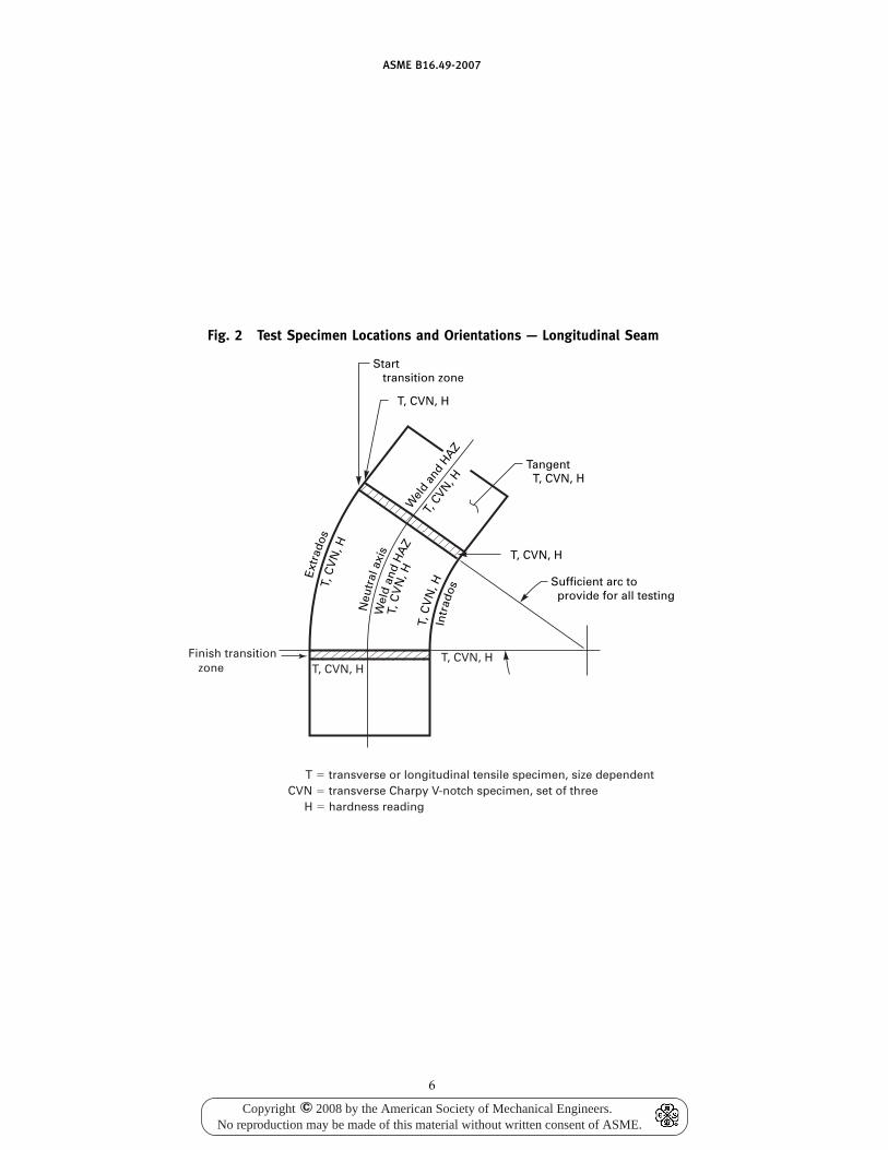
Fig. 2 Test Specimen Locations and Orientations — Longitudinal Seam
Tangent T, CVN, H
T, CVN, H
Sufficient arc to provide for all testing
T, CVN, H
Start transition zone
E
xtra
dos
Neu
tral
axi
s
Wel
d an
d H
AZ
T
, CV
N, H
T, C
VN
, H
T, C
VN
, H
In
trad
os
Wel
d an
d HAZ
T, C
VN, H
T, CVN, HFinish transition zone T, CVN, H
T � transverse or longitudinal tensile specimen, size dependentCVN � transverse Charpy V-notch specimen, set of three
H � hardness reading
6
Copyright 2008 by the American Society of Mechanical Engineers.No reproduction may be made of this material without written consent of ASME.
c

ASME B16.49-2007
Fig. 3 Test Specimen Locations and Orientations — Helical Seam
Top weld and HAZT, CVN, H
Bottom weld and HAZT, CVN, H
Extrados weld and HAZT, CVN, H
Intrados weld and HAZT, CVN, H
T, CVN, H
TangentT, CVN, H
Tangent weld and HAZT, CVN, H
T � transverse or longitudinal tensile specimen, size dependentCVN � transverse, Charpy V-notch specimen, set of three
H � hardness reading
T, CVN, H
T, CVN, H
T, CVN, HExtrados
T, CVN, H
Intrados
T, CVN, HTop
T, CVN, HBottom
T, CVN, H
Finish transition zone
Start transition zone
7
Copyright 2008 by the American Society of Mechanical Engineers.No reproduction may be made of this material without written consent of ASME.
c

ASME B16.49-2007
Table 3 Limits on Essential Variables
Essential Variable Limits of Variation
Pipe wall thickness ±3 mm (0.12 in.)Bend-radius-to-diameter +1R − 0
ratio (R/D0)Forming velocity ±2.5 mm (0.1 in.) per minForming temperature ±25°C (±50°F) from the
qualification temperatureCoil design No change allowedCoolant type No change allowedCooling water temperature ±15°C (±25°F)Flow rate/pressure of ±10% change in flow rate (or
coolant equivalent rate in pressure)Weld seam 15 deg from the neutral axisHeat treatment ±15°C (±25°F) in holding
temperature or any changein procedure
Induction heating power ±5%Induction heating ±20%
frequencySoaking time 0–15 min
9 HEAT TREATMENT
9.1 Type
Unless otherwise specified by the purchaser, eachbend shall be heat treated after bending (except as per-mitted in para. SR15.1) by one or more of the followingmethods:
(a) Stress Relieve or Temper. Uniformly, heat between480°C (900°F) and 675°C (1,250°F) and hold at tempera-ture for at least 30 min per 25 mm (1 in.) of thicknessat temperature, but no less than 30 min.
(b) Normalize. Heat above the transformation temper-ature range and hold at temperature for a minimum of20 min per 25 mm (1 in.) of thickness, but not less than20 min, and allow to cool in still air.
(c) Quench and Temper. Heat above the transformationtemperature range and hold at temperature for a mini-mum of 20 min per 25 mm (1 in.) of thickness and directquench in either water, oil, or a synthetic quenchant.Reheat to temper as defined above. Quench facilitiesshall be of sufficient size and shall be equipped to ensureproper and uniform cooling.
9.2 Equipment
All furnace heat-treatment equipment shall have arecording device that is calibrated at least quarterly.Heat-treat furnaces shall be surveyed annually, or at ashorter interval, as necessary to maintain uniformity ofheat treatment, or thermocouples shall be attached toeach furnace load. Thermocouples shall be calibrated atleast quarterly. Records shall be kept of furnace surveys,thermocouple calibrations, and if used, thermocouplereadings for each furnace load. The furnace shall becontrolled within a range of ±15°C (±25°F).
8
9.3 Heat-Treat Designators
Each bend and the material test report (see section 14)shall be identified with one of the following designatorsindicating final heat-treat condition:
N p normalizeNT p normalize and temperSR p stress relieveQT p quench and temper
10 QUALIFICATION BEND
10.1 Essential Variables
Prior to production bending, a qualification bend shallbe made and tested from each heat of material to demon-strate the suitability of the bending procedure to providea product meeting the required dimensions and materialproperties. This bend and tangent section shall be ofadequate length to obtain all the required test coupons.All bends (i.e., qualification and production) shall becompleted in a continuous heating cycle without stopsor starts, unless such areas are included in the bendprocedure qualification testing and found acceptable.Postbend heating for production bend dimensional cor-rections is not allowed unless covered in the qualifica-tion bend procedure. The procedure qualification shallaccount for the essential variables required to make abend. When any of these essential variables change, anew qualification bend must be made. The manufactur-er’s quality assurance program shall include proceduresthat ensure that the essential variables are properly con-trolled. This includes equipment calibration frequencyas necessary for control but in no case less than annually.Essential variables are shown in Table 3.
10.2 Records
10.2.1 Bend Qualification Procedure. Each manu-facturer shall prepare a written procedure that demon-strates that bends having suitable properties such asstrength, ductility, and hardness can be formed by thatprocedure. These records shall be available for the pur-chaser ’s review. Changes in the essential variablesbeyond the limits of variation shown in Table 3 shallrequire a new qualification bend test and procedure.
10.2.2 Testing Results. All applicable testing resultsshall be part of the records.
11 TEST REQUIREMENTS
The testing requirements differ between the qualifica-tion bend and the production bends. The followingrequirements apply in the locations specified. The quali-fication bend testing shall be conducted on a bend repre-sentative of the final heat-treat condition. Theproduction bend tests shall be conducted on each bendin the same final heat-treat condition as that which pro-duced the qualification bend.
Copyright 2008 by the American Society of Mechanical Engineers.No reproduction may be made of this material without written consent of ASME.
c

ASME B16.49-2007
11.1 Qualification Bend Requirements
11.1.1 Tensile Testing. Transverse tensile samplesfor NPS 8 (DN 200) or larger shall be taken from thetangent, the transition zone, and the bend segment atboth the intrados and extrados for each lot of materialas shown in Fig. 2 or 3. For sizes smaller than NPS 8(DN 200), either transverse or longitudinal test speci-mens shall be used. If the tangents and/or transitionzones are not left integral to the bend, no tensile testsare required except on the bend. See Fig. 2 or 3.
11.1.2 Fracture Toughness Testing. A set of threetransverse Charpy V-notch impact specimens shall betaken from the tangent, the transition zones, and thebend at both the intrados and extrados for each lot ofmaterial. See Fig. 2 or 3 for locations. If the tangentsand/or transition zones are not left integral to the bend,no impact tests are required except on the bend. SeeFig. 2 or 3.
11.1.3 Weld Testing(a) Longitudinal Seams. The tensile, impact, and hard-
ness tests shall be performed on the pipe or cylinderlongitudinal seam weld at the locations shown in Fig. 2.Acceptance criteria shall be as specified in paras. 8.1,8.2, 8.3, and 11.1.4.
(b) Helical Seam. The tensile, impact, and hardnesstests shall be performed on the pipe or cylinder helicalseam at the locations shown in Fig. 3. Acceptance criteriashall be as specified in paras. 8.1, 8.2, 8.3, and 11.1.4.
11.1.4 Hardness Testing. The bend shall be testedfor average hardness in all the same locations as thetensile tests are taken as well as each transition zone.In addition, an average hardness reading shall be takenfrom a minimum of two locations in the bend at theextrados and intrados. The allowable difference betweenthe minimum and maximum hardness readings for aquadrant around the circumference is 30 Brinell hard-ness number, or equivalent, if another testing methodis used. See Fig. 2 or 3.
11.2 Production Bend RequirementsTo demonstrate uniformity between the qualification
and production bends, each production bend shall behardness tested in all the same locations as the qualifica-tion bend. In addition, hardness readings shall be takenfor each additional 30 deg of arc beyond the qualificationbend angle. All values within like quadrants aroundthe circumference shall be within the same range asdetermined in para. 11.1.4. No readings shall exceed themaximum specified in Table 1, and no average shallequate to a tensile strength less than the minimumrequired in Table 1 for the specified grade.
11.3 Testing ResultsThe bend shall be marked with the appropriate grade
symbol of Table 1 based on the test results for all loca-tions meeting the minimum values specified for that
9
grade. If the bend strength is different from the matingpipe, and the substitution of wall thickness for yieldstrength is used in accordance with para. 8.1, both thebend grade and the intended mating pipe grade shallbe marked on the bend (i.e., P414/X483).
12 DIMENSIONAL REQUIREMENTS
The dimensional requirements in section 12 shall bemet on each bend.
12.1 Ovality
Ovality shall be measured throughout the bend andtangents. The difference between the maximum andminimum outside diameter shall not exceed 3% of thenominal mating pipe outside diameter within the bendand 1% at the welding end. The purchaser and manufac-turer may agree to a different ovality tolerance (see para.SR15.3).
12.2 Outside Diameter
The outside diameter of each welding end shall bewithin 1% of the nominal mating pipe outside diameter.The diameter throughout the bend and the remainderof the tangents need only meet the ovality tolerance,unless the purchaser and manufacturer agree to othertolerances.
12.3 Wall Thickness
The wall thickness shall be checked in sufficient loca-tions throughout the bend to ensure that the minimumwall does not fall below 90% of the nominal mating wallthickness marked on the bend (or below the purchaser-specified minimum wall thickness). This below-tolerance allowance does not apply to those areas deter-mined to need reinforcement as a result of designrequirements of para. 2.2. Inspection shall be done usingcompression wave ultrasonic examination by calibratedequipment that meets a procedure developed by themanufacturer to ensure accurate readings.
12.4 Inside Diameter
12.4.1 Welding Ends. For NPS 36 (DN 900) andsmaller, the inside diameter tolerance at the bevel faceshall be ±2.5 mm (±0.10 in.). For larger sizes, the insidediameter tolerance shall be ±3 mm (±0.12 in.).
12.4.2 Body. Unless otherwise agreed to by thepurchaser, the average internal diameter at any locationin the bend shall not be less than 97% of the minimumspecified mating pipe internal diameter. Proof of confor-mance to this requirement shall be demonstrated bypassing a sphere or other suitable gaging device throughthe bend without assistance of power equipment.
Copyright 2008 by the American Society of Mechanical Engineers.No reproduction may be made of this material without written consent of ASME.
c

ASME B16.49-2007
12.5 End Preparation
Welding ends shall be beveled using ASME B16.25,Fig. 2 illustration (a) or Fig. 3 illustration (a) end prepara-tions, unless otherwise specified by the purchaser.
12.6 Bend Dimensional Tolerances
The bend angle, center-to-end dimensions, bendradius, chord lengths, squareness, and bend plane shallbe measured and recorded for each bend. The toleranceson the ordered dimensions shall be as follows:
Dimension Tolerance
Bend angle ±1⁄2 degBend radius ±1%Bend plane ±1 degEnd squareness
NPS 36 (DN 900) and smaller 2.4 mm (0.09 in.)Greater than NPS 36 (DN 900) 3 mm (0.12 in.)
Linear dimensionsNPS 24 (DN 600) and smaller ±5 mm (0.19 in.)Greater than NPS 24 (DN 600) ±6 mm (0.25 in.)
See Fig. 4, illustrations (a) and (b).
13 INSPECTION OF PRODUCTION BENDS
13.1 Workmanship and Finish
If required for inspection, all bends shall be gritblasted or shot blasted clean to a bright metal finish inaccordance with SSPC SP-6. All bends shall be visuallyexamined on all accessible surfaces for laminations,cracks, notches, gouges, arc burns, wrinkles, or otherinjurious defects. Surface imperfections shall beremoved by grinding or machining, provided they arenot deeper than allowed in para. 12.3. Repair by weldingof base metal or weld metal is not permitted withoutpurchaser approval. It is characteristic of the inductionprocess that an upset occurs at each tangent point (transi-tion) of a bend. These are of a cosmetic nature and arenot classified as injurious defects.
13.2 Nondestructive Examination
The entire extrados of each bend, from neutral axis toneutral axis including the weld seam, shall be a magneticparticle or liquid penetrant examined for injuriousdefects. The area shall be free of cracks, laps, or lamina-tions. All rounded indications greater than 3 mm(0.12 in.) in any direction shall be classified as imperfec-tions and shall be removed as required in para. 13.1.
13.3 Outside Inspection
An inspector representing the purchaser shall beauthorized access to areas of the manufacturer’s facilitythat involve the manufacture of the ordered bends. Alltesting records, welding records, etc., shall be availablefor inspection prior to shipment.
10
14 CERTIFICATION
A Certified Material Test Report (CMTR) shall be fur-nished listing as a minimum the following information:
(a) chemical composition (including CE)(b) tensile properties(c) impact properties(d) hardness results(e) heat treatment(f) bend qualification procedure(g) welded or seamless(h) nondestructive examination results(i) applicable supplementary requirements (paras.
SR15.1 through SR15.8)
SR15 SUPPLEMENTARY REQUIREMENTS
The supplementary requirements (paras. SR15.1through SR15.8) are not applicable to the product fur-nished to this Standard except when specified on thepurchase order or otherwise agreed upon. When speci-fied or agreed upon, supplementary requirements shallhave the same force as requirements of mandatory sec-tions 1 through 14. Each bend shall be marked withthe applicable supplementary requirement (e.g., SR15.1)after the normal marking required in para. 4.1.
SR15.1 Heat Treatment
Bends can be furnished in an “as-bent” condition. Theproperties of section 8 must be met for that heat ofmaterial offered. Each bend shall be identified with ABSR15.1 as the heat-treat designator.
SR15.2 Nondestructive Examination
Magnetic particle or liquid penetrant examinationshall be performed on the bend area including the intra-dos, extrados, and weld seam. No cracks are permitted.All other indications will be addressed by an agreementbetween the purchaser and manufacturer. All inspec-tions shall be done by personnel and proceduresapproved by the purchaser.
SR15.3 Segmentable Bends
Bends required to be suitable for segmentation shallbe provided with an ovality through the bend and tan-gents of 1% maximum.
SR15.4 Fracture Toughness
Notch toughness requirements other than those speci-fied shall be by agreement between the purchaser andmanufacturer. This can include lower test temperatures,greater absorbed energy requirements, or different sheararea requirements.
SR15.5 Sour Gas Applications
Bends required for sour gas applications shall be fur-nished to meet ANSI/NACE MR0175/ISO 15156.
Copyright 2008 by the American Society of Mechanical Engineers.No reproduction may be made of this material without written consent of ASME.
c

ASME B16.49-2007
Fig. 4 Measurement of Bend Angle and Out-of-Squareness
Center to end
Center to endCenterline axis
Centerline axis
Chord
Extension
Center of bend
Measurement of Bend Angle by
Measurement and Calculation
(a)
Bend angle
Bend angle
Offset
Out-of-squareness
Out-of-squareness
(b) Measurement of Out-of-Squareness
Out-of-squareness
Bend
ra
dius
11
Copyright 2008 by the American Society of Mechanical Engineers.No reproduction may be made of this material without written consent of ASME.
c

ASME B16.49-2007
SR15.6 Weld Seam Examination: UT
SR15.6.1 In lieu of radiography, each weld seam ina pipe or starting cylinder may be ultrasonically tested.Acceptance criteria shall be by agreement between thepurchaser and manufacturer.
SR15.6.2 Each bend shall be ultrasonically exam-ined for the full length of weld from bevel end to bevelend after forming and final heat treatment. Testing pro-cedure and acceptance standards shall be as agreed uponbetween the purchaser and manufacturer.
SR15.7 Weld Seam Examination: RTEach bend shall have the weld seam 100% radio-
graphed for the full length from bevel end to bevel end
12
after forming and final heat treatment. Testing procedureand acceptance standards shall be as agreed uponbetween the purchaser and manufacturer.
SR15.8 Chemistries
SR15.8.1 Alternative chemical requirements and/or lower carbon equivalent shall be as agreed to by thepurchaser and manufacturer.
SR15.8.2 Acceptance of previous bend qualifica-tion procedures based on similar material chemistriesshall be as agreed upon between the purchaser andmanufacturer. This can include variations to other essen-tial variable requirements if agreed upon.
Copyright 2008 by the American Society of Mechanical Engineers.No reproduction may be made of this material without written consent of ASME.
c

ASME B16.49-2007
MANDATORY APPENDIX IREFERENCES
The following is a list of publications referenced inthis Standard. The latest edition shall apply.
ANSI/NACE MR0175-03/ISO 15156-2003, SulfideStress Cracking Resistant Metallic Materials forOilfield Equipment
Publisher: National Association of Corrosion Engineers(NACE International), 1440 South Creek Drive,Houston, TX 77084-4906
ASME Boiler and Pressure Vessel Code, 2004 EditionASME B16.25-2003, Buttwelding EndsASME B31 Code for Pressure PipingASME B36.10M-2004, Welded and Seamless Wrought
Steel PipePublisher: The American Society of Mechanical
Engineers (ASME), Three Park Avenue, New York, NY10016-5990; Order Department: 22 Law Drive, P.O. Box2300, Fairfield, NJ 07007-2300
ASTM A 370-05, Standard Test Methods and Definitionsfor Mechanical Testing of Steel Products
13
ASTM E 29-06, Practice for Using Significant Digits inTest Data to Determine Conformance WithSpecifications
ASTM E 140-05�1, Hardness Conversion Table for MetalsPublisher: ASTM International (ASTM), 100 Barr Harbor
Drive, West Conshohocken, PA 19428-2959
ISO 6708-1995: Pipework compenents — Definition andselection of DN (nominal size)
ISO 9000-2000: Quality management systems —Fundamentals and vocabulary
ISO 9001-2000: Quality management systems —Requirements
ISO 9004-2000: Quality management systems —Guidelines for performance improvements
Publisher: International Organization for Standardiza-tion (ISO), 1 ch. de la Voie-Creuse, Case postale 56,CH-1211 Geneve 20, Switzerland/Suisse
SSPC SP-6, Commercial Blast CleaningPublisher: Society for Protective Coatings (SSPC), 40
24th Street, Pittsburgh, PA 15222-4656
Copyright 2008 by the American Society of Mechanical Engineers.No reproduction may be made of this material without written consent of ASME.
c

ASME B16.49-2007
NONMANDATORY APPENDIX AQUALITY SYSTEM PROGRAM
The products manufactured in accordance with thisStandard shall be produced under a quality system pro-gram following the principles of an appropriate stan-dard from the ISO 9000 series.1 A determination of theneed for registration and/or certification of the product
1 The series is also available from the American National Stan-dards Institute (ANSI) and the American Society for Quality Con-trol (ASQC) as American National Standards that are identifiedby the prefix “Q” replacing the prefix “ISO.” Each standard of theseries is listed in Mandatory Appendix I.
14
manufacturer’s quality system program by an indepen-dent organization shall be the responsibility of the man-ufacturer. Detailed documentation demonstratingprogram compliance shall be available to the purchaserat the manufacturer ’s facility. A written summarydescription of the program utilized by the product man-ufacturer shall be available to the purchaser uponrequest. The product manufacturer is defined as theentity whose name or trademark appears on the productin accordance with the marking or identificationrequiremens of this Standard.
Copyright 2008 by the American Society of Mechanical Engineers.No reproduction may be made of this material without written consent of ASME.
c

ASME B16.49-2007
NONMANDATORY APPENDIX BINDUCTION BEND DATA SHEET
SO#:
Bend Specification:
Bend Procedure Qualification Test Is Required for Each Representative Heat of Pipe.
Design Conditions
Pipe Specification:
Bend to Weld To:Size:
ASME B16.49 latest editionAPI 5L latest edition as minimum
Wall: Grade:
Bend Radius: DN (nominal diameter)
Bend Angle: Tangent Length:
One End
*Min. I.D. at Ends and in Body:
*NOTE: Vendor to supply pipe to meet the above design conditions and be sized at the ends to meet the following: (a) The ends of each bend are to be beveled to match the pipe to which it is to be welded (see Appendix I, Fig. I-5 of ASME B31.8, Gas Transmission and Distribution Piping Systems, for bevel detail for unequal wall thickness). (b) The allowable welding mismatch tolerance is 0.047 in. for walls up to 0.250 in. and 0.094 in. for walls 0.251 in. and greater.
Notch Toughness Properties Acceptance Criteria:
Minimum CL Length Required Between Bends (S bend only):
Field Segmentable Bend: Yes
Temperature of Charpy Testing:
Quote Order #:
Induction Bend Data Sheet
Project Ref:
No
Coating Required: Yes No
Both
15
Copyright 2008 by the American Society of Mechanical Engineers.No reproduction may be made of this material without written consent of ASME.
c

AMERICAN NATIONAL STANDARDS FOR PIPING,PIPE FLANGES, FITTINGS, AND VALVES
Scheme for the Identification of Piping Systems. . . . . . . . . . . . . . . . . . . . . . . . . . . . . . . . . . . . . . . . . . . . . . . . . . . . . . . . . . . . . . . . . . . A13.1-1996Pipe Threads, General Purpose (Inch) . . . . . . . . . . . . . . . . . . . . . . . . . . . . . . . . . . . . . . . . . . . . . . . . . . . . . . . . . . . . . . . . . . .B1.20.1-1983(R1992)Dryseal Pipe Threads (Inch) . . . . . . . . . . . . . . . . . . . . . . . . . . . . . . . . . . . . . . . . . . . . . . . . . . . . . . . . . . . . . . . . . . . . . . . . . . . B1.20.3-1976(R1998)Cast Iron Pipe Flanges and Flanged Fittings: Classes 25, 125, and 250 . . . . . . . . . . . . . . . . . . . . . . . . . . . . . . . . . . . . . . . . . . . . . . . . B16.1-1998Malleable Iron Threaded Fittings: Classes 150 and 300. . . . . . . . . . . . . . . . . . . . . . . . . . . . . . . . . . . . . . . . . . . . . . . . . . . . . . . . . . . . . B16.3-1998Gray Iron Threaded Fittings: Classes 125 and 250 . . . . . . . . . . . . . . . . . . . . . . . . . . . . . . . . . . . . . . . . . . . . . . . . . . . . . . . . . . . . . . . . . B16.4-1998Pipe Flanges and Flanged Fittings (NPS 1⁄2 Through NPS 24) . . . . . . . . . . . . . . . . . . . . . . . . . . . . . . . . . . . . . . . . . . . . . . . . . . . . . . . . B16.5-1996Factory-Made Wrought Buttwelding Fittings. . . . . . . . . . . . . . . . . . . . . . . . . . . . . . . . . . . . . . . . . . . . . . . . . . . . . . . . . . . . . . . . . . . . . . . B16.9-2001Face-to-Face and End-to-End Dimensions of Valves . . . . . . . . . . . . . . . . . . . . . . . . . . . . . . . . . . . . . . . . . . . . . . . . . . . . . . . . . . . . . . . B16.10-2000Forged Fittings, Socket-Welding and Threaded . . . . . . . . . . . . . . . . . . . . . . . . . . . . . . . . . . . . . . . . . . . . . . . . . . . . . . . . . . . . . . . . . . . B16.11-2001Cast Iron Threaded Drainage Fittings . . . . . . . . . . . . . . . . . . . . . . . . . . . . . . . . . . . . . . . . . . . . . . . . . . . . . . . . . . . . . . . . . . . . . . . . . . . B16.12-1998Ferrous Pipe Plugs, Bushings, and Locknuts with Pipe Threads . . . . . . . . . . . . . . . . . . . . . . . . . . . . . . . . . . . . . . . . . . . . . . . . . . . . . B16.14-1991Cast Bronze Threaded Fittings: Classes 125 and 250. . . . . . . . . . . . . . . . . . . . . . . . . . . . . . . . . . . . . . . . . . . . . . . . . . . . . . . B16.15-1985(R1994)Cast Copper Alloy Solder Joint Pressure Fittings . . . . . . . . . . . . . . . . . . . . . . . . . . . . . . . . . . . . . . . . . . . . . . . . . . . . . . . . . . . B16.18-1984(R1994)Metallic Gaskets for Pipe Flanges: Ring-Joint, Spiral-Wound, and Jacketed . . . . . . . . . . . . . . . . . . . . . . . . . . . . . . . . . . . . . . . . . . . . . B16.20-1998Nonmetallic Flat Gaskets for Pipe Flanges . . . . . . . . . . . . . . . . . . . . . . . . . . . . . . . . . . . . . . . . . . . . . . . . . . . . . . . . . . . . . . . . . . . . . . . B16.21-1992Wrought Copper and Copper Alloy Solder Joint Pressure Fittings. . . . . . . . . . . . . . . . . . . . . . . . . . . . . . . . . . . . . . . . . . . . . . . . . . . . . B16.22-1995Cast Copper Alloy Solder Joint Drainage Fittings — DWV. . . . . . . . . . . . . . . . . . . . . . . . . . . . . . . . . . . . . . . . . . . . . . . . . . . . . . . . . . . . B16.23-1992Cast Copper Alloy Pipe Flanges and Flanged Fittings: Classes 150, 300,
600, 900, 1500, and 2500 . . . . . . . . . . . . . . . . . . . . . . . . . . . . . . . . . . . . . . . . . . . . . . . . . . . . . . . . . . . . . . . . . . . . . . . . . . . . . . . . . B16.24-2006Buttwelding Ends. . . . . . . . . . . . . . . . . . . . . . . . . . . . . . . . . . . . . . . . . . . . . . . . . . . . . . . . . . . . . . . . . . . . . . . . . . . . . . . . . . . . . . . . . . . B16.25-2007Cast Copper Alloy Fittings for Flared Copper Tubes. . . . . . . . . . . . . . . . . . . . . . . . . . . . . . . . . . . . . . . . . . . . . . . . . . . . . . . . . . . . . . . . B16.26-1988Wrought Steel Buttwelding Short Radius Elbows and Returns . . . . . . . . . . . . . . . . . . . . . . . . . . . . . . . . . . . . . . . . . . . . . . . . . . . . . . . B16.28-1994Wrought Copper and Wrought Copper Alloy Solder Joint Drainage Fittings — DWV. . . . . . . . . . . . . . . . . . . . . . . . . . . . . . . . . . . . . . . B16.29-1994Manually Operated Metallic Gas Valves for Use in Gas Piping Systems up
to 125 psig (Sizes 1⁄2 Through 2). . . . . . . . . . . . . . . . . . . . . . . . . . . . . . . . . . . . . . . . . . . . . . . . . . . . . . . . . . . . . . . . . . . . . . . . . . . . B16.33-1990Valves — Flanged, Threaded, and Welding End. . . . . . . . . . . . . . . . . . . . . . . . . . . . . . . . . . . . . . . . . . . . . . . . . . . . . . . . . . . . . . . . . . . B16.34-1996Orifice Flanges . . . . . . . . . . . . . . . . . . . . . . . . . . . . . . . . . . . . . . . . . . . . . . . . . . . . . . . . . . . . . . . . . . . . . . . . . . . . . . . . . . . . . . . . . . . . . B16.36-1996Large Metallic Valves for Gas Distribution (Manually Operated, NPS 21⁄2 to 12,
125 psig Maximum). . . . . . . . . . . . . . . . . . . . . . . . . . . . . . . . . . . . . . . . . . . . . . . . . . . . . . . . . . . . . . . . . . . . . . . . . . . . . . . . B16.38-1985(R1994)Malleable Iron Threaded Pipe Unions . . . . . . . . . . . . . . . . . . . . . . . . . . . . . . . . . . . . . . . . . . . . . . . . . . . . . . . . . . . . . . . . . . . . . . . . . . B16.39-1998Manually Operated Thermoplastic Gas Shutoffs and Valves in Gas
Distribution Systems . . . . . . . . . . . . . . . . . . . . . . . . . . . . . . . . . . . . . . . . . . . . . . . . . . . . . . . . . . . . . . . . . . . . . . . . . . . . . . . B16.40-1985(R1994)Functional Qualification Requirements for Power Operated Active
Valve Assemblies for Nuclear Power Plants . . . . . . . . . . . . . . . . . . . . . . . . . . . . . . . . . . . . . . . . . . . . . . . . . . . . . . . . . . . . . B16.41-1983(R1989)Ductile Iron Pipe Flanges and Flanged Fittings, Classes 150 and 300 . . . . . . . . . . . . . . . . . . . . . . . . . . . . . . . . . . . . . . . . . . . . . . . . B16.42-1998Manually Operated Metallic Gas Valves for Use in House Piping Systems . . . . . . . . . . . . . . . . . . . . . . . . . . . . . . . . . . . . . . . . . . . . . B16.44-1995Cast Iron Fittings for Sovent® Drainage Systems. . . . . . . . . . . . . . . . . . . . . . . . . . . . . . . . . . . . . . . . . . . . . . . . . . . . . . . . . . . . . . . . . . B16.45-1998Large Diameter Steel Flanges (NPS 26 Through NPS 60) . . . . . . . . . . . . . . . . . . . . . . . . . . . . . . . . . . . . . . . . . . . . . . . . . . . . . . . . . . . B16.47-1996Steel Line Blanks. . . . . . . . . . . . . . . . . . . . . . . . . . . . . . . . . . . . . . . . . . . . . . . . . . . . . . . . . . . . . . . . . . . . . . . . . . . . . . . . . . . . . . . . . . . B16.48-1997Factory-Made, Wrought Steel, Buttwelding Induction Bends for Transportation
and Distribution Systems . . . . . . . . . . . . . . . . . . . . . . . . . . . . . . . . . . . . . . . . . . . . . . . . . . . . . . . . . . . . . . . . . . . . . . . . . . . . . . . . . . B16.49-2007Power Piping . . . . . . . . . . . . . . . . . . . . . . . . . . . . . . . . . . . . . . . . . . . . . . . . . . . . . . . . . . . . . . . . . . . . . . . . . . . . . . . . . . . . . . . . . . . . . . . B31.1-1998Fuel Gas Piping (not an ANSI standard). . . . . . . . . . . . . . . . . . . . . . . . . . . . . . . . . . . . . . . . . . . . . . . . . . . . . . . . . . . . . . . . . . . . . . . . . . B31.2-1968Process Piping . . . . . . . . . . . . . . . . . . . . . . . . . . . . . . . . . . . . . . . . . . . . . . . . . . . . . . . . . . . . . . . . . . . . . . . . . . . . . . . . . . . . . . . . . . . . . . B31.3-1999Pipeline Transportation Systems for Liquid Hydrocarbons and Other Liquids. . . . . . . . . . . . . . . . . . . . . . . . . . . . . . . . . . . . . . . . . . . . B31.4-1998Refrigeration Piping and Heat Exchanger Components . . . . . . . . . . . . . . . . . . . . . . . . . . . . . . . . . . . . . . . . . . . . . . . . . . . . . . . . . . . . . . B31.5-2000Gas Transmission and Distribution Piping Systems . . . . . . . . . . . . . . . . . . . . . . . . . . . . . . . . . . . . . . . . . . . . . . . . . . . . . . . . . . . . . . . . B31.8-1999Building Services Piping . . . . . . . . . . . . . . . . . . . . . . . . . . . . . . . . . . . . . . . . . . . . . . . . . . . . . . . . . . . . . . . . . . . . . . . . . . . . . . . . . . . . . . B31.9-1996Slurry Transportation Piping Systems. . . . . . . . . . . . . . . . . . . . . . . . . . . . . . . . . . . . . . . . . . . . . . . . . . . . . . . . . . . . . . . . . . . . B31.11-1989(R1998)Manual for Determining the Remaining Strength of Corroded Pipelines . . . . . . . . . . . . . . . . . . . . . . . . . . . . . . . . . . . . . . . . . . . . . . . . B31G-1991Welded and Seamless Wrought Steel Pipe . . . . . . . . . . . . . . . . . . . . . . . . . . . . . . . . . . . . . . . . . . . . . . . . . . . . . . . . . . . . . . . . . . . . B36.10M-1996Stainless Steel Pipe . . . . . . . . . . . . . . . . . . . . . . . . . . . . . . . . . . . . . . . . . . . . . . . . . . . . . . . . . . . . . . . . . . . . . . . . . . . . . . . . B36.19M-1985(R1994)Self-Operated and Power-Operated Safety-Related Valves Functional
Specification Standard . . . . . . . . . . . . . . . . . . . . . . . . . . . . . . . . . . . . . . . . . . . . . . . . . . . . . . . . . . . . . . . . . . . . . . . . . . . . . N278.1-1975(R1992)
The ASME Publications Catalog shows a complete list of all the Standards published by the Society. For a complimentary catalog, or the latestinformation about our publications, call 1-800-THE-ASME (1-800-843-2763).
Copyright 2008 by the American Society of Mechanical Engineers.No reproduction may be made of this material without written consent of ASME.
c

J15607
ASME B16.49-2007
Copyright 2008 by the American Society of Mechanical Engineers.No reproduction may be made of this material without written consent of ASME.
c