Understand Units of Radiometric Measurement Convert Between Different Radiometric Units

5 FACTORS INFLUENCING RADIOMETRIC TEMPERATURE MEASUREMENTS

CONTENTS Page
Introduction 2
1. Radiometry and Surface Characteristics 3
2. Emissivity 4
3. Reflectivity 5
4. Effects of Atmosphere 6
5. Resolution 7
Summary 9
1

INTRODUCTION Thermal imaging is a powerful capability that can set your next product design apart from the competition. In addition to being able to see clearly in total darkness without any additional illumination, thermal cameras let you detect and display the minute temperature differences of every object within the field of view.
These temperature differences can be used to show qualitative differences in relative temperature – that one set of objects is warmer or colder than surrounding objects, for instance – or it can let your customers gather accurate, non-contact temperature measurements. A thermal camera can even let you do both at once, and track temperature trends over time.
Not all applications need quantitative temperature measurements. Qualitative imagery can still have the hottest or coldest items in the scene colorized to alert the user to temperatures that exceed a certain threshold. Firefighting and security cameras routinely make use of this functionality.
If you do want to create a product that can gather accurate temperature measurements, there are a number of things that must be kept in mind that could greatly affect the accuracy of those measurements. This paper will give you an overview of the most common of those factors.
2
A radiometric thermal camera measures the temperature of a surface by interpreting the intensity of an infrared signal reaching the camera.
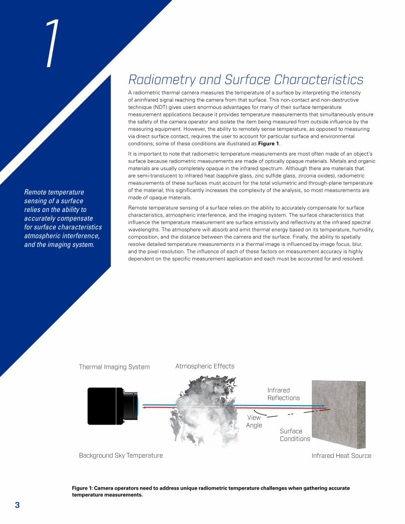
Radiometry and Surface Characteristics A radiometric thermal camera measures the temperature of a surface by interpreting the intensity of aninfrared signal reaching the camera from that surface. This non-contact and non-destructive technique (NDT) gives users enormous advantages for many of their surface temperature measurement applications because it provides temperature measurements that simultaneously ensure the safety of the camera operator and isolate the item being measured from outside influence by the measuring equipment. However, the ability to remotely sense temperature, as opposed to measuring via direct surface contact, requires the user to account for particular surface and environmental conditions; some of these conditions are illustrated as Figure 1.
It is important to note that radiometric temperature measurements are most often made of an object’s surface because radiometric measurements are made of optically opaque materials. Metals and organic materials are usually completely opaque in the infrared spectrum. Although there are materials that are semi-translucent to infrared heat (sapphire glass, zinc sulfide glass, zirconia oxides), radiometric measurements of these surfaces must account for the total volumetric and through-plane temperature of the material; this significantly increases the complexity of the analysis, so most measurements are made of opaque materials.
Remote temperature sensing of a surface relies on the ability to accurately compensate for surface characteristics, atmospheric interference, and the imaging system. The surface characteristics that influence the temperature measurement are surface emissivity and reflectivity at the infrared spectral wavelengths. The atmosphere will absorb and emit thermal energy based on its temperature, humidity, composition, and the distance between the camera and the surface. Finally, the ability to spatially resolve detailed temperature measurements in a thermal image is influenced by image focus, blur, and the pixel resolution. The influence of each of these factors on measurement accuracy is highly dependent on the specific measurement application and each must be accounted for and resolved.
Thermal Imaging System Atmospheric Effects
Background Sky Temperature
Surface Conditions
Infrared Reflections
Infrared Heat Source
ViewAngle
3
1
Remote temperature sensing of a surface relies on the ability to accurately compensate for surface characteristics atmospheric interference, and the imaging system.
Figure 1: Camera operators need to address unique radiometric temperature challenges when gathering accurate temperature measurements.
1

EmissivityEmissivity is a measure of a surface’s efficiency in emitting thermal energy relative to a perfect emitter, called a “blackbody”. It directly scales the intensity of the thermal emission, and all real values are less than 1.0. Generally speaking, an object’s emissivity is determined by the materials it’s composed of and its surface texture. Organic materials like human skin, soil, unpainted or varnished wood, and rocks are typically highly emissive. An object’s emissivity is highly dependent on its surface composition, and can also be affected by its roughness, oxidation, spectral wavelength, temperature, and possibly viewing angle. Shiny or polished materials, on the other hand, are more reflective. A measurement that does not account for the real emissivity of a surface will appear “colder” than it actually is.
For agricultural applications, many organic materials and materials with very rough surfaces have emissivity values approaching 1.0. For other applications, including power line and solar cell inspection, the surface might be a highly polished glass or metal, both of which can have much lower emissivity values. As a reference, Table 1 demonstrates the wide range of emissivity values that may be encountered in radiometric applications.
Emissivity is a measure of a surface’s efficiency in emitting thermal energy relative to that of a perfect blackbody.
4
Material Description Emissivity [n.d.] 1, 2
Asphalt 0.90 to 0.98Concrete 0.92Soil, dry 0.90Soil, wet 0.95
Wood 0.90Water 0.92 to 0.96
Ice 0.96 to 0.98Snow 0.83Brick 0.93 to 0.96
Lacquer, paint 0.80 to 0.95Lacquer, flat black 0.97
Textiles 0.90Skin, human 0.98
Aluminum, polished 0.04 to 0.06Aluminum, anodised 0.55
Steel, rusty 0.69Steel, stainless 0.16 to 0.45
Table 1: Emissivity values for common materials. Tabulated for reference only; emissivity is dependent on surface morphology, layers, oxidation, spectral wavelength, view angle, temperature and view angle.
2
Figure 2: Every thermal image includes materials with different levels of emissivity and reflectivity. Understanding these properties is vital for accurate temperature measurements.

ReflectivityA camera close to a surface is sensing the heat sustained from the surface temperature and the reflected background environmental temperature. It is very challenging to make temperature measurements of a highly reflective surface because the image is influenced by the background thermal reflections. When taking measurements outside, for example, an unpainted and clean metal roof can appear colder than it actually is because the shiny roof reflects the sky above it.
Consider the case of a stainless steel sheet on a rooftop, 0.80 reflectivity and 0.20 emissivity. A radiometric temperature measurement made under these conditions would be highly biased towards the reflected background temperature of the sky. A clear sky may have a background temperature that is typically well below 0°C, and possibly as low as -20°C. The actual sky background temperature will vary depending on atmospheric conditions and time of day.
Similarly, reflection of the sun in the thermal image will appear as sun glints, and radiometric temperatures of the sun glints can be hundreds of degrees inaccurate. It is advisable to take a sequence of images of the surface from different angles to reduce the influence of any single sun glint. However, care must be taken not make measurements at exceedingly oblique angles because reflections can change and become more of a factor as viewing angles increase. Alternatively, a very close range and straight on measurements can result in the camera viewing a reflection of itself and result in inaccurate measurements. Figure 3 illustrates the view angle challenges for radiometric temperature measurements and recommends making measurements less than 60° normal to the surface.
Much like emissivity, the reflectivity of a surface is highly dependent on the surface morphology and roughness. Since reflectivity (R) is related to emissivity (ε) by R=1-ε, the importance of reflectivity can be greatly reduced by making measurements of surfaces with very high emissivity, ideally greater than 0.90. For measurements of controlled surfaces, such as a steel tank on a rooftop, high emissivity/low reflectivity matte-flat black paint can be used to make “measurement patches” that result in highly reproducible measurements.
5
Taking accurate temperature measurements of a highly reflective surface can be complicated by the background thermal reflections seen in the surface being measured.
3
Thermal Imaging System
High Reflections,Low Emissivity
Camera Reflectionat Close Distances
High Reflections,Low Emissivity
Best View Angles
60°
Best View Angles
Infrared Heat Source
Figure 3: Radiometric temperature measurements should avoid straight-on measurements when imaging highly reflective materials to reduce direct camera reflection and avoid oblique angles to reduce overall reflection.

Effects of AtmosphereThe earth’s atmosphere interferes with the thermal image by absorbing and emitting infraredradiation based on the air density, air temperature, relative humidity (RH), and distance between the object surface and the camera. The atmospheric transmission between the camera and the surface can change the radiometric temperature measurement and is a measure of the effective heat reaching the camera. Not accounting for this atmospheric extinction will result in radiometric measurements that appear colder than the actual surface temperature.
Consider a very warm and humid day, a 100-meter air path (35°C air temperature, 80% RH) has a theoretical transmission of 80%. That means that only 80% of the thermal radiative heat emitted from surface will reach the camera. If this atmospheric transmission loss is not accounted for, then a camera looking at a 50°C object with a known emissivity of 0.97 will read 47.6°C – this is a 2.4°C error caused by the air path alone! The best way to mitigate the atmospheric transmission effect is to minimize the distance between the camera and the surface. For example, at 10 meters the transmission is 96% and the radiometric temperature uncorrected for air path is 49.5°C.
The atmosphere can affect the temperature measurements in other unexpected ways. Measurements should always be performed in the absence of rain, snow, smoke, dust, or any other obscurants because they too will reduce the atmospheric transmission and change the background temperature. Finally, remember that radiometric measurements only report the surface temperature and the surface temperature may be very sensitive to strong winds.
Figure 4: Atmospheric moisture like fog can greatly reduce a thermal camera’s detection range. Also note the thermal reflections of the person and building on the surface of the water.
6
The earth’s atmosphere impacts radiometric measurements by absorbing and emitting infrared radiation.
4

Thermal Imaging System
0 10 20 30 40 50
1.00
0.75
0.50
0.25
0.00
Target Diameter in Pixels
Radiometric/ActualTemperature [N.D.]
Poor Weak Excellent
ResolutionA radiometric thermal image describing a surface provides a radiometric temperature measurement for each pixel. A very small surface in the image will become exceeding difficult to accurately measure as the number of pixels describing the dimensions of the surface is diminished. The spot-size effect is this degradation in measurement accuracy due to the effects of optical distortion, diffraction, stray light, and sensor image processing that result in a washed-out image. Not accounting for the spot-size effect will yield measurements that may be highly influenced by nearby surfaces. For example, a warm object may appear colder and a cold object may appear warmer than the actual temperatures. Although the spot-size effect may be highly dependent on the particular thermal camera, FLIR laboratory measurements suggest that a measurement spot in the thermal image should be at least 10 pixels in diameter to report a meaningful measurement and a 20-pixel diameter is sufficiently large to negate the spot-size effect. Figure 5 illustrates the improvement in radiometric temperature accuracy as the spot-size is increased.
The spot-size effect becomes increasingly relevant as the distance between the surface and the camera is increased and the number of pixels describing each spatial feature is reduced. The number of pixels used to resolve the surface area of an object is dependent on the pixel pitch, focal length, distance from the camera to the surface, and the smallest characteristic size (length, diameter) of the surface, Figure 6 illustrates these factors. The number of pixels (N) used to resolve an object is evaluated by the ratio of the camera angular subtense and pixel instantaneous field of view
N=α/IFOVp
where, the surface to camera angular subtense α=d⁄s is the ratio of the distance between the camera to object surface (d) and the size of the object (s). The instantaneous field of view (IFOVp) of each camera pixel is calculated by taking the ratio of the pixel pitch (p) and focal length (f), IFOVp=p⁄f. These relationships can be manipulated to find the maximum recommended measurement distance, smallest necessary object size, and camera characteristics for any particular radiometric temperature application. Consider a Tau 2 camera with a 13mm lens, 640 by 512 pixel resolution sensor, and 17 μm pixel pitch. Assuming that the camera is 20 meters from its target, a 30 centimeter square surface directly below the camera will only be 12 by 12 pixels in a thermal image. Table 2 gives the maximum recommended distance between the camera and an object to maintain at least a 10-pixel resolution in the thermal image for different object sizes.
7
Not accounting for the spot-size effect will yield measurements that may be highly influenced by nearby surfaces.
Figure 5: The spot-size effect, caused by optical and physical characteristics of the camera, is most relevant for remote temperature sensing.
5
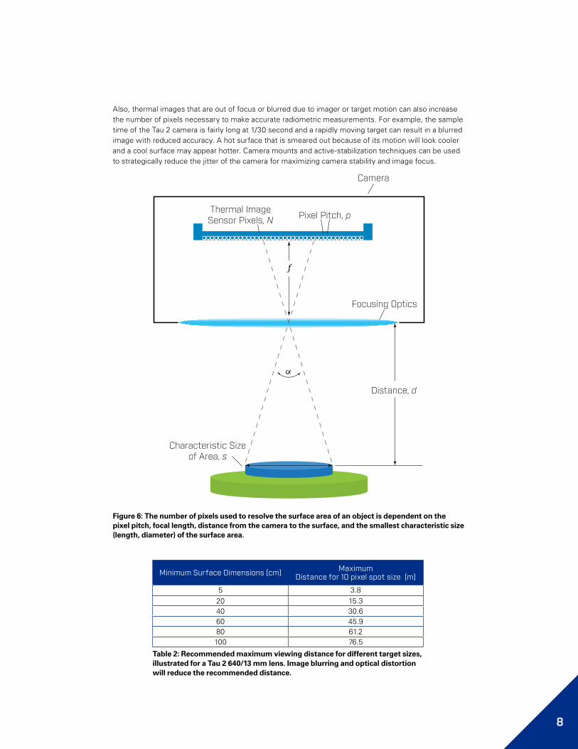
Thermal ImageSensor Pixels, N
Characteristic Sizeof Area, s
Focusing Optics
Distance, d
Pixel Pitch, p
Camera
Figure 6: The number of pixels used to resolve the surface area of an object is dependent on the pixel pitch, focal length, distance from the camera to the surface, and the smallest characteristic size (length, diameter) of the surface area.
8
Minimum Surface Dimensions (cm) Maximum Distance for 10 pixel spot size (m)
5 3.8 20 15.3 40 30.6 60 45.9 80 61.2 100 76.5
Table 2: Recommended maximum viewing distance for different target sizes, illustrated for a Tau 2 640/13 mm lens. Image blurring and optical distortion will reduce the recommended distance.
Also, thermal images that are out of focus or blurred due to imager or target motion can also increase the number of pixels necessary to make accurate radiometric measurements. For example, the sample time of the Tau 2 camera is fairly long at 1/30 second and a rapidly moving target can result in a blurred image with reduced accuracy. A hot surface that is smeared out because of its motion will look cooler and a cool surface may appear hotter. Camera mounts and active-stabilization techniques can be used to strategically reduce the jitter of the camera for maximizing camera stability and image focus.

9
Summary In summary, there are many factors that may influence the accuracy of radiometric surface temperature measurements. For surfaces with low emissivity and high reflection, straight-on and oblique view angles should be avoided to reduce the impact of reflections and exacerbated oblique reflection. The surface emissivity should be high to reduce the impact of background temperature reflection and sun glints, ideally greater than 0.90. Alternatively, increasing the surface emissivity can be achieved by coupling a rough surface texture with high emissivity, matte flat black paint to mitigate the impact of uncertain emissivity and high reflectivity.
The atmospheric transmission factors can be largely negated by making measurements to within 10 meters or less of the target surface and in a cool and clear atmospheric setting. These conditions mitigate the impact of air temperature, relative humidity, and air particulates. For longer distances, the atmospheric conditions (distance, humidity, temperature) will need to be well characterized to calculate the atmospheric transmission. Measurements greater than 10 meters are further impacted by the spot-size effect when the number of pixels describing any particular surface drops and the ability to make measurements of very small objects is severely impacted. Although it is important to make measurements with a spot-size diameter of at least 10 pixels, more pixels are necessary for blurred and out of focus images.
1 G. Gaussorgues and S. Chomet, Infrared Thermography. Springer, 1994, page 47.
2 M. Modest, Radiative Heat Transfer. Elsevier Academic Press, 3rd Edition.

Notes
10

HEADQUARTERSFLIR Systems, Inc.27700 SW Parkway AveWilsonville, OR 97070
SANTA BARBARAFLIR Systems, Inc.6769 Hollister Ave.Goleta, CA 93117PH: 1 805.964.9797
EUROPEFLIR Systems, Inc.Luxemburgstraat 22321 MeerBelgiumPH: +32 (0) 3665 5100
CHINA – BEIJINGFLIR Systems Co, LTDRoom 502, West Wing, Hanwei BuildingNo. 7 Guanghua AveChaoyang District, Beijing 100004, ChinaPhone: +86 10-59797755
www.flir.com/oemNASDAQ: FLIR
Equipment described herein is subject to US export regulations and may require a license prior to export. Diversion contrary to US law is prohibited. Imagery for illustration purposes only. Specifications are subject to change without notice. ©2016 FLIR Systems, Inc. All rights reserved. 11/18/2016
16-0539 12p