factors affecting internal resistance/emf of the cell
29
CERTIFICATE This is to certify that this dissertation is a bonafide record of the project work done by ______________ of class XII (science) REG NO.______________ under my guidance and supervision in partialfulfillment of the requirements for appearing in AISSCE March 2014Principal Teacher in ChargeExternal Examiner No____________
-
Upload
yogesh-baghel -
Category
Science
-
view
4.209 -
download
73
Transcript of factors affecting internal resistance/emf of the cell

CERTIFICATE This is to certify that this dissertation is a
bonafide record of the project work done by ______________ of class XII
(science) REG NO.______________ under my
guidance and supervision in partialfulfillment of
the requirements for appearing in AISSCE
March 2014Principal Teacher in ChargeExternal Examiner No____________

Internal resistance
1. Internal Resistance, EMF and
Oscilloscopes
2. What we are going to achieve today
o Creating power from lemons
o Find out about internal resistance of batteries
o Know what is the electromotive force is
o Use an oscilloscope to measure the
frequency and voltage from an signal
generator
3. Using lemons, limes and potatoes to power an LED zinc copper
4. Making Batteries There is nothing special about batteries – but these have a high internal resistance. R l What do you think the best way to minimise the internal

resistance of your battery? Think about resistivity (lemon is a poor conductor)
5. Batteries What is the main energy transfer in a battery? Electrical energy This is powered by two 1.5 V AA cells in series - what is the supply voltage? What is the emf of the supply? After a while the battery needs to be replaced; why? What determines how quickly it runs down? What determines how much current is drawn from the supply?
6. EMF Electromotive Force
EMF is the external work expended per unit
of charge to produce an electric potential
difference across two open-circuited terminals
o This is the same definition as voltage but on
an open circuit (no current flow)
o Why is this definition important?

7. Batteries have internal resistance The circuit now has two resistors in The internal resistance of the battery, r is very small. R is much larger The total resistance of this circuit is R total = R +r I = E / (R+r)
8. Batteries have internal resistance As charge goes around the circuit the sum of emfs must equal the sum of voltage drops leading to EMF = I R + I r The terminal voltage is equal to I R so this can be rearranged to give: V = E – I r and interpreted as terminal voltage = emf – ‘lost volts’
9. R -small R total = r + R -small The current will now be larger as the total resistance of the circuit is much lower The voltage lost across r V = I (large) r The voltage lost will now be a problem This case is of a small load resistance connected to a battery is seen in a starter motor on a car

10. Starter motor on a conventional car The headlamps are connected in parallel across a twelve-volt battery. The starter motor is also in parallel controlled by the ignition switch. Since the starter motor has a very low resistance it demands a very high current (say 60 A). The battery itself has a low internal resistance (say 0.01 Ω). The headlamps themselves draw a much lower current (they have a higher resistance) Lamp R Starter motor Ignition switch 12V What will happen to the lights?
11. A use of high internal resistance
12. Quick Questions
o .1. A 9.0 V battery has an internal resistance of 12.0
o (a) What is the potential difference across
its terminals when it is supplying a current of 50.0 mA?

o What is the maximum current this battery
could supply?
o Draw a sketch graph to show how the
terminal potential difference varies with the current supplied if the internal resistance
remains constant. How could the internal
resistance be obtained from the graph?
o and the current rises to 60 mA. What is the
emf and internal resistance of the cell? . When the wearer turns up the volume, the
resistance is changed to 100 2. A cell in a deaf aid supplies a current of 25.0 mA
through a resistance of 400
V = E – I r V = IR E = I(R +r) You need to set up a simultaneous equation
13. E = 10 + (25 x 10 -3 x 114.3) = 12.86
V I VAnswers 1. (a) pd = E – I r = 9 – (50 x 10 -3 x 12) = 8.4 V (b) Max current = E/r = 9 / 12 = 0.75 A 2. E = I(R +r) E = 25 x 10 -3 (400 + r) and E = 60 x 10 -3

(100 + r) So 25 x 10 -3 (400 + r) = 60 x 10 -3 (100 + r) so r = 114.3
14. Oscilloscope Use the signal generator to create A/C (alternating current) on the Oscilloscope Draw 2 signals of 2 different frequencies Work out the frequency of the Oscilloscope Add the magnitude of the wave height How do you use an oscilloscope as a dc and ac voltmeter? How do you use it to measure frequency?
15. Voltage what the average value of an ac voltage or current is over a whole number of cycles? power is calculated by P = IV , both I and V change sign together, so power is always positive
16. Positive power calling the maximum value of I p V p and a minimum of zero 0V P = I p V p Average power = ½ I p V p P = 1/2 I p V p = 1/2 I p 2 R = 1/2 V p 2 / R (using V = I R)
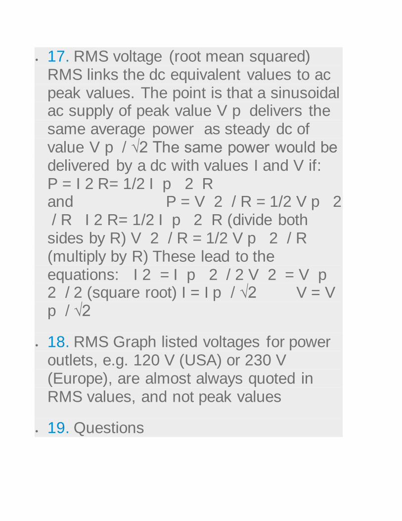
17. RMS voltage (root mean squared) RMS links the dc equivalent values to ac peak values. The point is that a sinusoidal ac supply of peak value V p delivers the same average power as steady dc of value V p / √2 The same power would be delivered by a dc with values I and V if: P = I 2 R= 1/2 I p 2 R and P = V 2 / R = 1/2 V p 2 / R I 2 R= 1/2 I p 2 R (divide both sides by R) V 2 / R = 1/2 V p 2 / R (multiply by R) These lead to the equations: I 2 = I p 2 / 2 V 2 = V p 2 / 2 (square root) I = I p / √2 V = V p / √2
18. RMS Graph listed voltages for power outlets, e.g. 120 V (USA) or 230 V (Europe), are almost always quoted in RMS values, and not peak values
19. Questions

o 1. The mains ac supply in some countries is
110 V r.m.s at 50 Hz (sinusoidal).
o (a) What is the peak value of voltage?
o (b) What is the peak-to-peak value of
voltage?
o (c) How long does one cycle of this ac supply last?
o (d) A 100 W lamp is designed for use with
110 V ac What is the resistance of its
filament? (use r.m.s. value for V)
o 2. Which will light a lamp more brightly, 12
V peak ac or 12 V steady dc? Explain.
o UK mains ac has an r.m.s. value of 230 V
and a frequency of 50 Hz. Sketch a graph of voltage against time for one cycle of this ac
and include values for peak voltage and
time period on the axes.
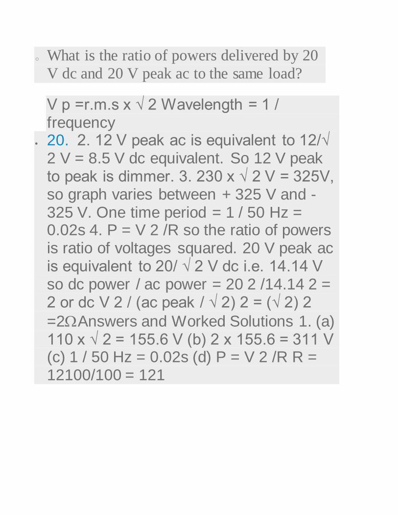
o What is the ratio of powers delivered by 20
V dc and 20 V peak ac to the same load?
V p =r.m.s x √ 2 Wavelength = 1 / frequency
20. 2. 12 V peak ac is equivalent to 12/√ 2 V = 8.5 V dc equivalent. So 12 V peak to peak is dimmer. 3. 230 x √ 2 V = 325V, so graph varies between + 325 V and -325 V. One time period = 1 / 50 Hz = 0.02s 4. P = V 2 /R so the ratio of powers is ratio of voltages squared. 20 V peak ac is equivalent to 20/ √ 2 V dc i.e. 14.14 V so dc power / ac power = 20 2 /14.14 2 = 2 or dc V 2 / (ac peak / √ 2) 2 = (√ 2) 2
=2Answers and Worked Solutions 1. (a) 110 x √ 2 = 155.6 V (b) 2 x 155.6 = 311 V (c) 1 / 50 Hz = 0.02s (d) P = V 2 /R R = 12100/100 = 121


Current electricity
1. K V, NAL CAMPUS, B’LORE •
CURRENT ELECTRICIY
2. 1. Electric Current 2. Conventional Current 3. Drift Velocity of electrons and current 4. Current Density 5. Ohm’s Law 6. Resistance, Resistivity, Conductance & Conductivity 7. Temperature dependence of resistance 8. Colour Codes for Carbon Resistors 9. Series and Parallel combination of resistors 10. EMF and Potential Difference of a cell 11. Internal Resistance of a cell 12. Series and
Parallel combination of cells
3. Electric Current: The electric current is defined as the charge flowing through any section of the conductor in
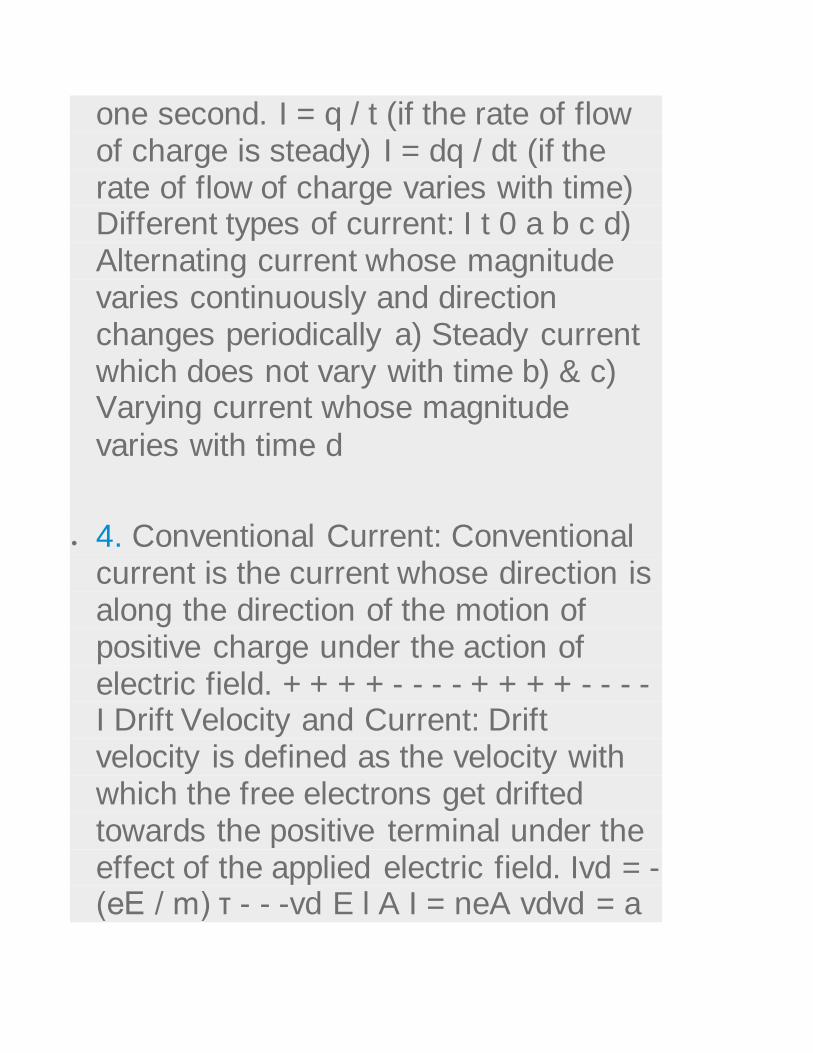
one second. I = q / t (if the rate of flow of charge is steady) I = dq / dt (if the rate of flow of charge varies with time) Different types of current: I t 0 a b c d) Alternating current whose magnitude varies continuously and direction changes periodically a) Steady current which does not vary with time b) & c) Varying current whose magnitude
varies with time d
4. Conventional Current: Conventional current is the current whose direction is along the direction of the motion of positive charge under the action of electric field. + + + + - - - - + + + + - - - - I Drift Velocity and Current: Drift velocity is defined as the velocity with which the free electrons get drifted towards the positive terminal under the effect of the applied electric field. Ivd = - (eE / m) τ - - -vd E l A I = neA vdvd = a
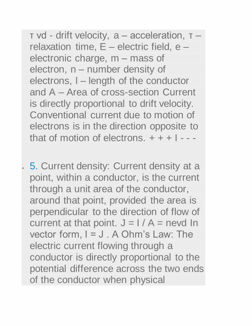
τ vd - drift velocity, a – acceleration, τ – relaxation time, E – electric field, e – electronic charge, m – mass of electron, n – number density of electrons, l – length of the conductor and A – Area of cross-section Current is directly proportional to drift velocity. Conventional current due to motion of electrons is in the direction opposite to
that of motion of electrons. + + + I - - -
5. Current density: Current density at a point, within a conductor, is the current through a unit area of the conductor, around that point, provided the area is perpendicular to the direction of flow of current at that point. J = I / A = nevd In vector form, I = J . A Ohm’s Law: The electric current flowing through a conductor is directly proportional to the potential difference across the two ends of the conductor when physical

conditions such as temperature, mechanical strain, etc. remain the
same. I V I α V or V α I or V = R I V I 0
6. Resistance: The resistance of conductor is the opposition offered by the conductor to the flow of electric current through it. R = V / I Resistance in terms of physical features of the conductor: I = neA | vd | I = neA (e |E| / m) τ ne2 Aτ m V l I = ne2 Aτ V I = ml ne2 τ A R = m l A R = ρ l where ρ = ne2 τ m is resistivity or specific resistance Resistance is directly proportional to length and inversely proportional to cross-sectional area of the conductor and depends on nature of material. Resistivity depends upon nature of material and not on the geometrical
dimensions of the conductor.

7. When temperature increases, vd decreases and ρ increases. When l increases, vd decreases. Relations between vd , ρ, l, E, J and V: ρ = E / J = E / nevd vd = E /(neρ) vd = V /(neρl) (since, J = I / A = nevd ) (since, E = V / l ) Conductance and conductivity: Conductance is the reciprocal of resistance. Its S.I unit is mho. Conductivity is the reciprocal of resistivity. Its S.I unit is mho / m. Temperature dependence of Resistances: ne2 τ A R = m l When temperature increases, the no. of collisions increases due to more internal energy and relaxation time decreases. Therefore, Resistance increases. Temperature coefficient of Resistance: R0 t α = Rt – R0 R1t2 – R2t1 α = R2 – R1 or R0 – Resistance at 0°C Rt – Resistance at t°C R1 – Resistance at t1°C R2 – Resistance at
t2°CIf R2 < R1, then α is – ve.

8. Colour code for carbon resistors: B V B Gold G R B Silver B V B The first two rings from the end give the first two significant figures of resistance in ohm. The third ring indicates the decimal multiplier. The last ring indicates the tolerance in per cent about the indicated value. Eg. AB x 10C ± D % ohm 17 x 100 = 17 ± 5% Ω 52 x 106 ± 10% Ω 52 x 100 = 52 ± 20% Ω Letter Colour Number Colour Tolerance B Black 0 Gold 5% B Brown 1 Silver 10% R Red 2 No colour 20% O Orange 3 Y Yellow 4 G Green 5 B Blue 6 V Violet 7 G Grey 8 W White 9 B B ROY of Great
Britain has Very Good Wife
9. Another Colour code for carbon resistors: Yellow Body Blue Dot Gold Ring YRB Gold 42 x 106 ± 5% Ω Red Ends i) The colour of the body gives the first significant figure. ii) The colour of
the ends gives the second significant figure. iii) The colour of the dot gives the decimal multipier. iv) The colour of the ring gives the tolerance. Series combination of resistors: Parallel combination of resistors: R = R1 + R2 + R3 R is greater than the greatest of all.R1 R2 R3 R1 R2 R3 1/R =1/R1 + 1/R2 + 1/R3 R is smaller than the
smallest of all.
10. Sources of emf: The electro motive force is the maximum potential difference between the two electrodes of the cell when no current is drawn from the cell. Comparison of EMF and P.D: EMF Potential Difference 1 EMF is the maximum potential difference between the two electrodes of the cell when no current is drawn from the cell i.e. when the circuit is open. P.D is the difference of potentials between any

two points in a closed circuit. 2 It is independent of the resistance of the circuit. It is proportional to the resistance between the given points. 3 The term ‘emf’ is used only for the source of emf. It is measured between any two points of the circuit. 4 It is greater than the potential difference between any two points in a circuit. However, p.d. is greater than emf when
the cell is being charged.
11. Internal Resistance of a cell: The opposition offered by the electrolyte of the cell to the flow of electric current through it is called the internal resistance of the cell. Factors affecting Internal Resistance of a cell: i) Larger the separation between the electrodes of the cell, more the length of the electrolyte through which current has to flow and consequently a higher value of
internal resistance. ii) Greater the conductivity of the electrolyte, lesser is the internal resistance of the cell. i.e. internal resistance depends on the nature of the electrolyte. iii) The internal resistance of a cell is inversely proportional to the common area of the electrodes dipping in the electrolyte. iv) The internal resistance of a cell depends on the nature of the electrodes. R rE II E = V + v = IR + Ir = I (R + r) I = E / (R + r) This relation is
called circuit equation. V v
12. Internal Resistance of a cell in terms of E,V and R: R rE II V v E = V + v = V + Ir Ir = E - V Dividing by IR = V, Ir E – V = IR V E r = ( - 1) R V Determination of Internal Resistance of a cell by voltmeter method: r K R.B (R) V + r II R.B (R) K V + Open circuit (No current is drawn) EMF (E) is measured

Closed circuit (Current is drawn)
Potential Difference (V) is measured
13. Cells in Series combination: Cells are connected in series when they are joined end to end so that the same quantity of electricity must flow through each cell. R II V rE rE rE NOTE: 1. The emf of the battery is the sum of the individual emfs 2. The current in each cell is the same and is identical with the current in the entire arrangement. 3. The total internal resistance of the battery is the sum of the individual internal resistances. Total emf of the battery = nE (for n no. of identical cells) Total Internal resistance of the battery = nr Total resistance of the circuit = nr + R Current I = nE nr + R (i) If R << nr, then I = E / r (ii) If nr << R, then I = n (E / R) Conclusion: When internal resistance is negligible in comparison

to the external resistance, then the cells are connected in series to get
maximum current.
14. Cells in Parallel combination: Cells are said to be connected in parallel when they are joined positive to positive and negative to negative such that current is divided between the cells. NOTE: 1. The emf of the battery is the same as that of a single cell. 2. The current in the external circuit is divided equally among the cells. 3. The reciprocal of the total internal resistance is the sum of the reciprocals of the individual internal resistances. Total emf of the battery = E Total Internal resistance of the battery = r / n Total resistance of the circuit = (r / n) + R Current I = nE nR + r (i) If R << r/n, then I = n(E / r) (ii) If r/n << R, then I = E / R Conclusion: When external

resistance is negligible in comparison to the internal resistance, then the cells are connected in parallel to get maximum current. V R II rE rE rE

Inernal resistance
A practical electrical power source which is a
linear electric circuit may, according to Thévenin's
theorem, be represented as an ideal voltage
source in series with an impedance. This
resistance is termed theinternal resistance of the
source. When the power source delivers current,
the measured voltage output is lower than the no-
load voltage; the difference is the voltage drop
(the product of current and resistance) caused by
the internal resistance. The concept of internal
resistance applies to all kinds of electrical sources
and is useful for analyzing many types of
electrical circuits.
Batteries
Batteries can be approximately modeled as a
voltage source in series with a resistance. The
internal resistance of a battery is dependent on
the specific battery's size, chemical properties,
age, temperature and the discharge current. It has

an electronic component due to the resistivity of
the battery's component materials and an ionic
component due to electrochemical factors such as
electrolyte conductivity, ion mobility, and electrode
surface area. Measurement of the internal
resistance of a battery is a guide to its condition,
but may not apply at other than the test
conditions. Measurement with an alternating
current, typically at a frequency of 1kHz, may
underestimate the resistance, as the frequency
may be too high to take into account the slower
electrochemical processes. Internal resistance
depends upon temperature; for example, a
fresh Energizer E91 AA alkaline primary battery
drops from about 0.9 ohms at -40 °C, where the
low temperature reduces ion mobility, to about
0.15 ohms at room temperature and about 0.1
ohms at 40 °C.[1]
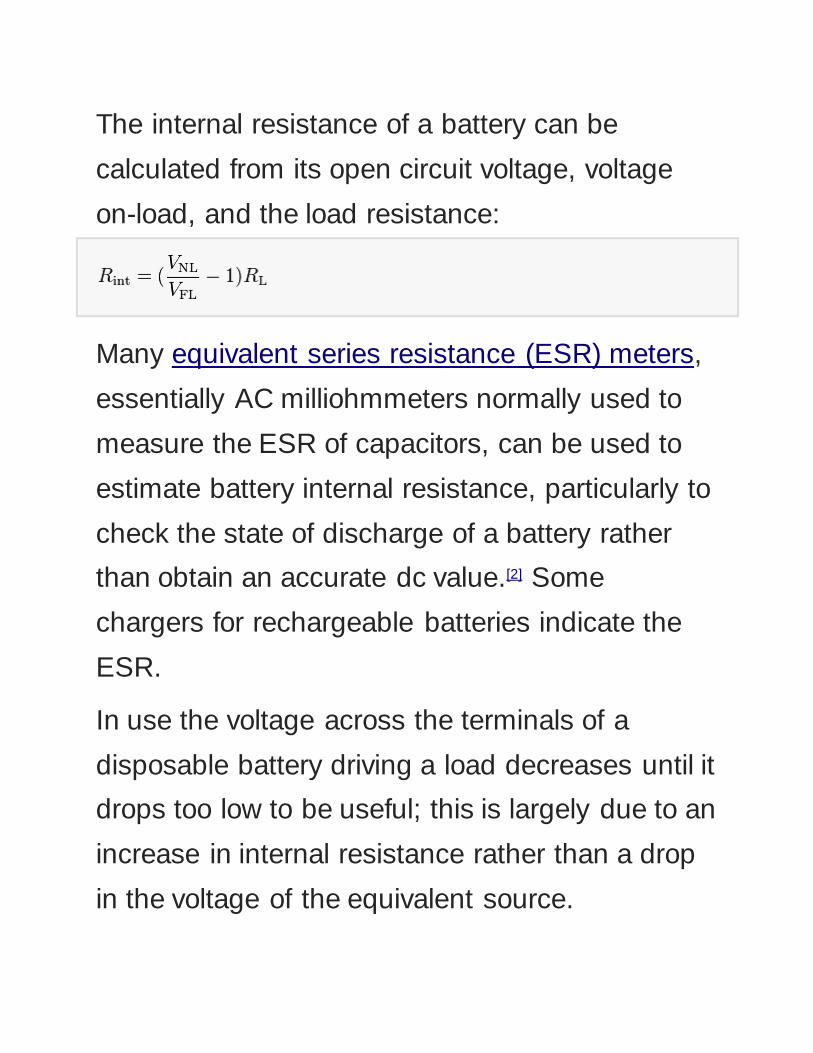
The internal resistance of a battery can be
calculated from its open circuit voltage, voltage
on-load, and the load resistance:
Many equivalent series resistance (ESR) meters,
essentially AC milliohmmeters normally used to
measure the ESR of capacitors, can be used to
estimate battery internal resistance, particularly to
check the state of discharge of a battery rather
than obtain an accurate dc value.[2] Some
chargers for rechargeable batteries indicate the
ESR.
In use the voltage across the terminals of a
disposable battery driving a load decreases until it
drops too low to be useful; this is largely due to an
increase in internal resistance rather than a drop
in the voltage of the equivalent source.

With rechargeable lithium polymer batteries the
internal resistance is largely independent of the
state of charge, but increases as the battery ages,
thus is a good indicator of expected life.

EMF measurements are measurements of
ambient (surrounding) electromagnetic fields that
are performed using particular sensors or probes,
such as EMF meters. These probes can be
generally considered as antennas although with
different characteristics. In fact probes should not
perturb the electromagnetic field and must
prevent coupling and reflection as much as
possible in order to obtain precise results. There
are two main types of EMF measurements:
broadband measurements performed using a
broadband probe, that is a device which senses
any signal across a wide range of frequencies
and is usually made with three independent
diode detectors;
frequency selective measurements in which the
measurement system consists of a field
antenna and a frequency selective receiver or
spectrum analyzer allowing to monitor the
frequency range of interest.
EMF probes may respond to fields only on one
axis, or may be tri-axial, showing componets of
the field in three directions at once. Amplified,
active, probes can improve measurement
precision and sensitivity but their active
components may limit their speed of response.


![Higher EMF and Internal Resistance Questions25368]4._H_EMF_and_Int_Res... · Higher EMF and Internal Resistance Questions 1. State the definition of the following terms: a) EMF. b)](https://static.fdocuments.in/doc/165x107/5b57e7ba7f8b9a31668b530b/higher-emf-and-internal-resistance-253684hemfandintres-higher-emf.jpg)