Facility Design and Process Utilities -...
55
933 Biopharmaceutical Processing. https://doi.org/10.1016/B978-0-08-100623-8.00045-1 © 2018 Elsevier Ltd. All rights reserved. Facility Design and Process Utilities John Joseph GE Healthcare, Little Chalfond, United Kingdom 45.1 INTRODUCTION The first biopharmaceutical facilities for large-scale cultivation of recombinant micro-organisms were designed and com- missioned decades ago [1]. The relatively meager competitive landscape of the early 1990s, caused in part by patent protec- tion of novel drugs, meant that biopharmaceutical manufacturing facilities were built to produce large volumes of single blockbuster products year after year at considerable cost. At the time, however, the ends, characterized by multi-billion dollar revenues, justified the considerable expenditures required. Since then, there has been a steady evolution in the design and construction of research, development, and manufactur- ing facilities borne out of the changing regulatory, technological, and commercial landscape of this industry. The global biopharmaceutical industry of today reflects increased competition through a greater prevalence of large molecule drugs (both innovator and biosimilar) and an expansion in the number of personalised targeted products [2]. These trends have given rise to biopharmaceutical products with limited production runs, highly specific manufacturing requirements, and genotype-specific products. Although the industry has long focused on finding ways to develop and launch new and innovative therapies in less time and at lower costs, in recent years it has increasingly turned its attention toward improvements not only in process manufacturing technologies, but also in evaluation of the gains that can be made through facility design and construction methodologies [3]. The key aim of all facility design is to assure manufacturing operations provide a continuously consistent high-quality product. That is, for facility design to be functional, it must first ensure that products being produced meet or exceed the minimum required attributes of product safety, potency, purity, and efficacy [4]. However, to be considered a success, the design and operation must meet both the patient and business needs of satisfying demand requirements at the lowest cost. A critical driver in achieving consistent product quality is a facility that uses operational excellence to remain in com- pliance with appropriate regulatory guidelines. Regulatory guidelines provide the basis of Good Manufacturing Practices (cGMPs) and process validation, which define the standards by which facilities are inspected and product approval sub- missions are made. In biopharmaceutical manufacturing in particular, meeting all business drivers is wholly dependent on compliance with regulatory authorities. Complete knowledge, understanding, and implementation of all the applicable guidelines is required to assure compliance at all times and hence is needed for successful facility design. The other major consideration of the facility design is cost. The aim is to minimize the initial capital expenditure (CAPEX) required prior to gaining any revenue from manufactured products. CAPEX is a major component of the busi- ness resources required to bring a biopharmaceutical facility to fruition. Assets with faster implementation schedules allow for deferral of resources, spending, and an improved cash flow. In terms of biopharmaceutical facilities, the overall cost of manufacturing product can be viewed as a combination of operating and capital costs. With the current cost pressures on the industry, understanding and controlling both is critical. High utilization rates almost always translate into cost-effective facilities. The aim is to design facilities that are sized properly and have the characteristics and capabilities that allow them to run at a high production rate to achieve business ob- jectives. In the biopharmaceutical industry, flexibility can be a key enabler to improved facility utilization. If a manufacturing facility is flexible, with the capability to quickly and efficiently supply different multiproduct manufacturing requirements, it is far more likely to have a high utilization rate because it can handle a wide variety of the enterprise’s manufacturing require- ments. Of equal importance is that a flexible facility can support an emerging product pipeline where individual products may have various probabilities of success. Designing facilities with this level of flexibility protects companies from owning capital assets that require significant capital to reconfigure to support new products in the future. Thus, a facility that can Chapter 45
Transcript of Facility Design and Process Utilities -...

933Biopharmaceutical Processing. https://doi.org/10.1016/B978-0-08-100623-8.00045-1© 2018 Elsevier Ltd. All rights reserved.
Facility Design and Process UtilitiesJohn JosephGE Healthcare, Little Chalfond, United Kingdom
45.1 INTRODUCTION
The first biopharmaceutical facilities for large-scale cultivation of recombinant micro-organisms were designed and com-missioned decades ago [1]. The relatively meager competitive landscape of the early 1990s, caused in part by patent protec-tion of novel drugs, meant that biopharmaceutical manufacturing facilities were built to produce large volumes of single blockbuster products year after year at considerable cost. At the time, however, the ends, characterized by multi-billion dollar revenues, justified the considerable expenditures required.
Since then, there has been a steady evolution in the design and construction of research, development, and manufactur-ing facilities borne out of the changing regulatory, technological, and commercial landscape of this industry. The global biopharmaceutical industry of today reflects increased competition through a greater prevalence of large molecule drugs (both innovator and biosimilar) and an expansion in the number of personalised targeted products [2]. These trends have given rise to biopharmaceutical products with limited production runs, highly specific manufacturing requirements, and genotype-specific products.
Although the industry has long focused on finding ways to develop and launch new and innovative therapies in less time and at lower costs, in recent years it has increasingly turned its attention toward improvements not only in process manufacturing technologies, but also in evaluation of the gains that can be made through facility design and construction methodologies [3].
The key aim of all facility design is to assure manufacturing operations provide a continuously consistent high-quality product. That is, for facility design to be functional, it must first ensure that products being produced meet or exceed the minimum required attributes of product safety, potency, purity, and efficacy [4]. However, to be considered a success, the design and operation must meet both the patient and business needs of satisfying demand requirements at the lowest cost.
A critical driver in achieving consistent product quality is a facility that uses operational excellence to remain in com-pliance with appropriate regulatory guidelines. Regulatory guidelines provide the basis of Good Manufacturing Practices (cGMPs) and process validation, which define the standards by which facilities are inspected and product approval sub-missions are made. In biopharmaceutical manufacturing in particular, meeting all business drivers is wholly dependent on compliance with regulatory authorities. Complete knowledge, understanding, and implementation of all the applicable guidelines is required to assure compliance at all times and hence is needed for successful facility design.
The other major consideration of the facility design is cost. The aim is to minimize the initial capital expenditure (CAPEX) required prior to gaining any revenue from manufactured products. CAPEX is a major component of the busi-ness resources required to bring a biopharmaceutical facility to fruition. Assets with faster implementation schedules allow for deferral of resources, spending, and an improved cash flow. In terms of biopharmaceutical facilities, the overall cost of manufacturing product can be viewed as a combination of operating and capital costs. With the current cost pressures on the industry, understanding and controlling both is critical.
High utilization rates almost always translate into cost-effective facilities. The aim is to design facilities that are sized properly and have the characteristics and capabilities that allow them to run at a high production rate to achieve business ob-jectives. In the biopharmaceutical industry, flexibility can be a key enabler to improved facility utilization. If a manufacturing facility is flexible, with the capability to quickly and efficiently supply different multiproduct manufacturing requirements, it is far more likely to have a high utilization rate because it can handle a wide variety of the enterprise’s manufacturing require-ments. Of equal importance is that a flexible facility can support an emerging product pipeline where individual products may have various probabilities of success. Designing facilities with this level of flexibility protects companies from owning capital assets that require significant capital to reconfigure to support new products in the future. Thus, a facility that can
Chapter 45

934 SECTION | VII Facility Design and Operation
handle multiple phases of manufacturing for several products employing a variety of different processes is more likely to have a high utilization rate. In biopharmaceuticals, the facility must be capable of quickly and efficiently adapting to different multiproduct manufacturing requirements despite process problems and changing product demand.
Finally, the geographical location of the facility is a key business driver that requires consideration as the pharmaceuti-cal industry looks to meet significant unmet medical needs while generating sources of revenue. Many countries require local manufacturing for market access. The result is the need to configure future facilities to be rapidly and efficiently deployable for emerging markets by focusing on optimizing the combination of capital costs, timelines, regulatory consid-erations, operational drivers, and the design of the process.
In summary, the successful design of a biopharmaceutical facility must account for regulatory, technical, operational, and economic aspects simultaneously. There is unlikely to be an optimal balance among these factors; for instance, the most technically advanced facility addressing all operational and regulatory issues will seldom be the most economical. Conversely, a facility that is designed in the most economical fashion, while adhering to regulatory standards, may rarely be the most operationally efficient. Therefore, the designer and facility sponsor will need to select a solution that reflects the best compromise between these factors. However, one aspect around which there can be no compromise is the facility design adherence to regulatory compliance.
45.2 THE MANUFACTURING LANDSCAPE
The construction or acquisition and licensing of physical production capacity for a new biopharmaceutical is an expensive and time-consuming project. Although a manufacturer requires some production capacity to support clinical testing, this is typically not sufficient to meet demand once a drug is approved. For a monoclonal antibody facility, building and licensing a new traditional commercial-scale plant can take 4–5 years and cost up to $800 million [5]. Even if a firm plans to produce the drug in an existing facility or outsource the product to a contract manufacturing organization, it typically takes several years and costs $100’s of millions to make necessary modifications, develop an effective approach for technology transfer, and complete FDA licensing [5]. Because biopharmaceuticals are difficult to characterize analytically, biopharmaceutical licens-ing has traditionally been tied to the facility in which the product is made. Thus, changing or adding to manufacturing capac-ity after a product is licensed is expensive and risky, so firms typically focus on having sufficient production capacity to meet future demand available at a single site at product launch, and are hesitant to change or expand capacity after that point [6].
Early facilities that were designed for single-product processes are now aging, putting them on the investment radar for upgrades to enable manufacturing diversity, and allow more efficient facility use. More than ever before, global engi-neering leaders are confronted with complex strategic and financial decisions when they seek to invest capital in new flex-ible pharmaceutical facilities or upgrade the flexibility of aging facilities for supply of pipeline products. Manufacturing facilities today are in a more flexible continuum than facilities were 20 years ago [7]. With increased competition and a reduction in the number of drug blockbusters, new facility designers have started to consider a reduction in the capital investment required both from the perspective of initial investment as well as depreciation costs. Recently, novel so-called “disposable" or “single-use" approaches to biopharmaceutical production utilizing, for example, one-time-use tank liners and mixers have become viable options, at small- to mid-scale production [8].These options take less time to build and install than traditional large stainless-steel tanks and processing equipment, and may allow for rapid ramp-up of capacity, as they are typically pre-validated, pre-sterilized, and stocked by vendors [6]. Because this capacity must be replaced each time it is used, it is likely that operating costs will be higher, although installation costs relative to traditional stainless steel approaches have the potential of being lower. As such, the evolution (as opposed to revolution) of unit operations utilising single-use technologies has forced a change in the traditional facility design paradigm.
45.3 CAPACITY PLANNING
The decision to design and build a new facility or expand an existing one almost always comes down to the business drivers of additional revenue and market share. For the biopharmaceutical industry, aligning capital expenditure (CAPEX) deci-sions with business strategy can help rationalize whether to make products in-house or to outsource their manufacture to a contract manufacturing organization (CMO) [9].
Manufacturers face one of the most unpredictable planning environments in any industry due to the uncertainty around the success of potential drug candidates during clinical trials, definition of market size and share for candidate drugs, per-formance of the manufacturing process (e.g., in terms of yields and ranges for improvements to existing processes), and obtaining licensing approvals. Waiting for full confidence in the success and development of candidate drugs before install-ing capacity could prolong time to market and therefore lead to losses in revenue.

Facility Design and Process Utilities Chapter | 45 935
The expenditure budget, cost of drug development, and speed to market required constrain the amount of capital that can be allocated to manufacturing within a specific time period [10]. This, together with the high investment for biopharmaceu-tical facilities, makes the strategic planning process for these high-value products a formidable task [11]. Each company must ascertain how much capacity it needs and in what time frame to better define its strategy for securing the infrastructure needed, be it outlaying their own capital for new buildings, retrofitting existing ones, or outsourcing production to contract manufacturing organizations (CMOs).
A multitude of unforeseen circumstances can skew capacity forecasts. Some of these could include reports of a serious adverse event, slow enrolment in clinical trials, sale of a parent company that is developing the drug, an unusually success-ful marketing strategy, provider motives and incentives, final cost to the patient, willingness for a payer or pharmacy benefit manager to reimburse the cost of a drug, a change in raw material availability, availability of new therapeutic alternatives, or new regulatory legislation.
In a Nature Reviews Drug Discovery study from 2013, investigators concluded that more than 60% of companies miss their demand forecasts by at least 40% [12]. A significant number of companies were also overly optimistic by more than 160% of the actual peak revenues that a product could generate. Even up to six years post-launch, forecasts were still found to be off the mark by as much as 45%. The researchers found that demand for oncology drugs was most commonly under-estimated, most likely because of the additional indications for which these drugs earned approval by the FDA after initial launch. This demand underestimation is an important finding considering the large number of biologic, immune-oncology therapeutics (with various proposed indications) that are currently in the pipeline. The authors found that analyst forecasts for generic therapies were also markedly off-target [12].
Including post-approval R&D costs, as well as costs associated with unsuccessful projects, the estimate for the aver-age out-of-pocket cost to develop a new compound was found to be $2,870 million (in 2013 U.S. dollars), according to an analysis by DiMasi et al. that appeared in the May 2016 issue of the Journal of Health Economics [13]. Even though there have been slight methodological differences in DiMasi et al.’s studies since 2003 (when the authors began looking at the cost of bringing a drug to market), his cost of development has still increased substantially since 2003. Additionally, per the authors of the study, “clinical success rates are substantially lower for the studies focused on more recent periods” [13]. Thus, because failure rates have increased and the cost of developing a drug has also increased so markedly, it is increas-ingly difficult to accurately predict the demand for a drug.
Indeed, many industry experts agree that predicting capacity will become even more problematic for pharmaceutical manu-facturers in the future because of market access issues. In Europe, because physicians seem to be more accepting of biosimilars, market penetration forecasts may be a bit clearer. But in the United States, physician acceptance and prescribing practices (as well as the interchangeability status of a biosimilar) may make launch and capacity predictions increasingly challenging [14].
When considering the capacity expansion of an existing facility or the construction of a new facility, a manufacturer typically doesn’t consider a single product in isolation: the firm is usually developing a portfolio of products, and may have a portfolio of capacity investment projects [6]. Firms generally commit to building or acquiring production capacity early enough in the trial process to ensure that this capacity will be ready at the time that the drug receives final approval. Of course, there is no guarantee that a new drug will pass all of the required phases of clinical trials, and in fact most drugs fail to show effectiveness at Phase II and Phase III of clinical studies. Indeed, the overall probability of a drug achieving clinical and regulatory approval is only 8% [15].
Thus, by committing to building or investing in a facility without carefully assessing the appropriate level of evidence that a drug will pass the required clinical trials, and by not updating this decision as information becomes available, the firm may be taking on excessive investment risk. Firms have a limited window of exclusive sales rights for any drug before generic drug makers enter the market and drive down prices, and this is typically the firm’s primary opportunity to recover enormous initial investment costs. The sooner production can start, the sooner revenue streams can be acquired and losses recovered. There is therefore a paradox, whereby investment decisions for facility planning need to be taken early enough to coincide with production readiness with success in the clinic. However, there is the very real risk that a candidate drug will not pass the required clinical trials, in which case the manufacturing firm could be taking excessive risk.
There are certain mitigation strategies that can be considered, however. In the case of MAbs, firms may develop produc-tion processes based on a platform approach (see Chapter 32). In this way, if one candidate drug fails in the clinic, another candidate within the portfolio, if successful, could still be implemented in the new facility without wholescale modification to the design and setup. Investment risk is therefore spread over many similar products. Several recent streams of research focus on strategies such as capacity procurement contracts, capacity pooling, and capacity outsourcing to mitigate capacity demand risk [14,16–19]. For established biopharmaceutical manufacturers with an already existing global network of manufacturing sites, consolidation of capacity may ease the burden on investment. For instance, optimization of the cam-paign strategies within different sites could free enough capacity to meet the manufacturing demands of the new candidates.

936 SECTION | VII Facility Design and Operation
Although biopharmaceutical firms do often outsource some of their production, the cost and time involved with prepar-ing contract manufacturing facilities for new products is significant [6]. The use of CMOs can be helpful when there are fluctuating capacity and demand conditions. This is notable in the mid to late phases of the clinic where the risk of drug fail-ure is still high enough to be a barrier to significant investment to in-house production needs. Utilization of existing CMO capacity removes the requirement for investment needed to establish in-house manufacturing capability. Furthermore, an operating staff and the scientific knowledge base already exist at the CMO.
The disadvantages of outsourcing mostly stem from the intimate knowledge a CMO will gain around the product and process for manufacture. Moreover, there is always a substantial risk that technology transfer from the parent company to the CMO will not be successful immediately. Conversely, if a CMO has its own proprietary manufacturing platform, a biopharma company cannot easily transfer the process back in-house or to another CMO. If the contract manufacturing agreement does not give the sponsor a license to this technology solely for the continued production of this specific biologic drug, the manu-facturing process will have to be partially redesigned, which is not feasible from a time and cost perspective [20]. In addition, many biopharmaceutical firms are concerned about the intellectual property implications of outsourcing manufacturing, par-ticularly because there is a good deal of ambiguity about the nature of intellectual property in biotechnology [21]. It should be noted, however, that there any many longstanding relationships between CMO and parent drug development companies, some of which have their own in-house capacity. In some cases, therefore, the significant ends justify the means.
The risks and stakes for being wrong are high whichever path (insourcing or outsourcing) is undertaken. The impact of overbuilding is most easily quantified because it involves specific costs. These include large capital investments that result in little return, supporting idle facilities with continued overhead, selling or leasing excess capacity not directly part of the manufacturing business, and likely the eventual sale of facilities at a loss. The risks due to underbuilding can be just as great, but they are often harder to quantify because they involve not only lost revenues, but also impacts on intangibles, such as from lost sales; from share gains by the competition affecting long-term sales; from reduced patient survival rates through inability to meet; from delays in expansion of product lines, which can lead to reduced market share; from delays in bringing product to market if clinical capacity is constrained; from lower profitability when outside manufacturing sources must be used to meet demand; and from long-term impact on company reputation and brand equity.
Before committing on a path forward a company may wish to evaluate the necessary requirements for a capacity expansion either for an existing infrastructure or new build. This could take place during a conceptual design study (see Section 45.9), whereby a preliminary cost estimation and project execution schedule could be generated. This will allow the company to make a more informed decision when comparing alternative strategies (e.g., outsourcing with a CMO). To undertake any facility design, however, a basic input would be the exact capacity output required from the facility at launch and potential future expansion as market penetration increases. This will determine the overarching requirements of production and thus allow estimation of infrastructure sizing.
Project definition for a new facility is intricately dependent on capacity and operational models. Required output de-mand of the facility over its lifetime is the key input to the facility design process (see Chapter 4). To meet the demand required, the facility will need to support a manufacturing process capable of achieving these targets. At this point in the overall project, the manufacturing process may not be wholly established. Technical data will be supplied from the process development or technical transfer groups, who would have established the process design and scale up (see Chapter 32).
45.4 FACILITY FUNCTIONAL NEEDS
Once the production capacity of the facility is determined, the overarching boundaries and constraints of the facility design are fixed. Regardless of the differing variables effecting design, generally, a typical biopharmaceutical facility has three basic interdependent functions that should be accommodated: [1] the core manufacturing process, [2] process support activities and [3] utility and mechanical systems. These are shown schematically in Fig. 45.1. Production capacity will determine the requirements and sizing of the core manufacturing process, which will in turn determine the sizing and requirements of the process support activities that will subsequently be in the input needed for determining the utility and mechanical systems. Throughout these determinations, however, adherence to current good manufacturing practices (cGMP) will be required.
1. The core manufacturing process, consisting of:The core manufacturing process is the heart of the production facility and is typically a prerequisite to the facility de-
sign project. It is the basis of the functional needs of the facility, and as such, dictates most aspects of design. Chapter 32 discusses the various strategies employed in designing a process for large-scale manufacture.
Upstream Processing (USP)—these steps include cell culture seed development, inoculum preparation, bioreactor or fermentation culturing and harvest. Upstream areas accommodate process steps that handle live organisms. Although

Facility Design and Process Utilities Chapter | 45 937
the demarcation between upstream and downstream activities varies with specific processes, upstream areas are gen-erally considered to end with a recovery step [4].Downstream Processing (DSP)—these include purification steps and bulk formulation. Downstream activities aim to render the product in its final bulk form in a transportable closed container prior to fill-finish activities. The DSP may be further physically divided based on segregation objectives (further explained in Section 45.5.2).
2. Process support activities:The specific process support function needed will depend on the unit operation and its purpose within the overall
manufacturing process. Therefore, once the core manufacturing process is defined, the required process support activi-ties and areas can be established. Invariably, the individual unit operation steps of the process include the use of several ancillary steps over and above product processing, to ensure optimal performance. These ancillary steps vary from the necessary addition of cell culture growth media to encourage optimal growth of cells and product, to the introduction of various buffer sets on a chromatography column to change the different ionic or other state of the resin or the product solution; or the inclusion of buffer flushes on a filtration step to increase the yield of the step. In addition to the prepara-tion of cell culture media (used in the USP areas) and buffer (used in harvest and DSP), areas are needed for equipment preparation, column packing, equipment cleaning, cell bank storage, and in-process control (IPC) analytics. These functions impact the quality of the product and serve as support to the core process functionality. Changes to the core process(es) impact the process support functions.
3. Utility and mechanical systems:These include facility utilities (water, electricity, and gas), clean utilities (clean water, USP purified and WFI; clean
air; and clean steam), waste collection and treatment systems and heating, ventilation, and air conditioning (HVAC) systems. Neither the core process nor the manufacturing support areas would be able to function without the appropriate utility and mechanical systems.
Neither the manufacturing process, nor the process support activities would be able to function without basic utilities such as electricity, gas, and water. These base utilities can be supplied to the facility from the local municipality. Gas can be used to supply a boiler to provide for heating within the facility. Similarly, the water needed can be used as potable (or town) water for washrooms, or for drinking, or for use around air humidification. However, water and constituent gases are also needed for the manufacturing process and therefore have a direct impact on product quality. For instance, oxygen, nitrogen, carbon dioxide, and compressed air are needed by certain unit operations (e.g., bioreactors) to function. Water is needed for buffer and cell culture media makeup and within certain steps of the manufacturing process. cGMP requirements necessitate that anything directly impacting the product (whether in its final or intermediate state) will need to be as con-taminant free as the required product quality at the end of the process to reduce the risk of contamination. As a result, both water and gas supplied to manufacturing (or manufacturing support) operations should be purified to the required standard as referenced within the cGMPs. Thus, the facility shall also have to support this utility purification process.
Media & bufferpreparation/
supply
Upstreamcell culturepropagation& harvest
Downstreampurification
Core manufacturing process
Chromatographycolumn packing
Equipmentclean/ steam in
place
Cell bankstorage
In-processcontrol
testing support
Filter integritytesting
In-processstorage rooms(cold/ambient)
Equipmentwashing/
sterilising out ofplace
Heating ventilation and air conditioning (HVAC)
Clean utility generation and supply
Process support activities
Utility/mechanical systems
Ancillary supportactivities
Warehousing
Quality control andAssurance (QA/QC)
Process developmentlaboratory
Technical utilitygeneration and supply
FIG. 45.1 Schematization of the interdependencies of the different functions that make up a biopharmaceutical facility.

938 SECTION | VII Facility Design and Operation
45.5 cGMP FACILITY DESIGN
Guidance for the design of biopharmaceutical facilities is provided by a set of regulations and recommendations outlined as Good Manufacturing Practices (GMPs). GMP guidelines focus on mechanisms that will ensure that a manufacturing facil-ity consistently produces and delivers a product of the expected quality. A single universal “GMP” standard or approach to biopharmaceutical facilities does not exist. The nature of the product and its processes greatly influence decisions based on appropriate interpretation of the relevant GMP.
45.5.1 Regulatory Compliance
Compliance with GMP is a legal requirement in all countries of the world, and is controlled and enforced by local health authorities through the inspection and granting of an approval for licensure to manufacture these products. GMP rules and regulations are continuously modified to allow adaption to technical progress and to address the demands of manufacturers for more explicit interpretation of regulatory guidelines by authorities. However, the guidelines leave considerable room for interpretation. As a result, these are often referred to as current GMP or cGMP to ensure that the application of the most recent guidance is adhered to. Facility design and operational practices will always be evaluated against cGMPs regardless of when licensure to manufacture was granted [22].
Facility design and operation must meet the cGMP requirements of the country into which the product is being sold and, in some cases, made [22]. The issue here is that in spite of efforts to better harmonize GMP guidelines throughout the globe via initiatives such as those from The International Council for Harmonisation of Technical Requirements for Pharmaceuticals for Human Use (ICH), the Pharmaceutical Inspection Convention and Pharmaceutical Inspection Co-operation Scheme (PICs) or the World Health Organisation (WHO) guidelines for GMP, differences still remain between the GMP guidance offered and interpretation of them by different countries. As a result, an early issue to be resolved before facility design can proceed is the regulatory basis for the project. It is important to identify which countries a product will be licensed in, and the corresponding regulatory agencies which must be satisfied [23].
What is universally understood, however, is that the requirements of cGMP and therefore, intrinsically, facility design are driven by consideration of the consistent preservation of product quality and purity during manufacture. Sources of potential contamination are multi-fold: arising from external particulates within the room environment, perhaps introduced by operating personnel; contamination of a purer process stage with intermediates incorrectly transferred from an earlier process stage; incorrect raw material usage for a given campaign; leaching of product contacting surfaces or contamination caused by carry over from previous activities or by insufficient/inefficient cleaning or change-over between batches of the same product or different product campaigns. The aim of facility design is to try to minimize (ideally, to eliminate) the risk of contamination occurring within the facility.
Key to a successful manufacturing licensure effort is a well-defined manufacturing process that is seamlessly integrated with the facility. In defining the manufacturing process, there are several drivers that will have a significant impact on the facility design. The synergy among the product, the process, and the facility will become apparent. The large majority of biomanufacturing operations are not designed to produce sterile drug substance. Even if aseptic manufacturing standards are implemented, the focus is on bioburden control. In bioburden-controlled processing, the distinction between upstream and downstream operations is important. The upstream operations (seed inoculation and cell culture fermentation) are commonly designed as axenic operations that imply the need for a greater level of product protection. Downstream opera-tions (recovery, purification, and bulk filling) are operated as bioburden-control processes; again necessitating the need for contamination control, but to predetermined levels based on the product/process attributes [24].
Generally, it is the transition points within a process and facility that increase the risk of contamination. Goods or materials that are transferred into a cleaner environment must be cleaned in some way to ensure no transfer of potential contamination. Examples of these transition points could be entry of material into a unit operation, entry and exit of personnel within a pro-cessing room, insufficient cleaning protocols, incompatible product contacting surfaces, crossing of waste or contaminated equipment/materials with clean product within the facility. Several design concepts are recommended by cGMP guidelines and are used by facility designers to protect the homogeneity of the product with a view to (a) preventing contamination and (b) mitigating the risk of contamination even occurring. Usually, these concepts are realized through the practice of segregation.
45.5.2 The Concept of Segregation
Segregation practices form the fundamental design strategy for the prevention of cross- contamination and protection of quality of the final bulk and intermediate products throughout the manufacturing process.
Facility Design and Process Utilities Chapter | 45 939
As a result, segregation is a central paradigm in process and facility design, which ensures product protection in the biopharmaceutical operations. Segregation can be accomplished by:
1. Process design, through system closure2. Space and environmental controls3. Procedural and temporal segregation
Segregation by Process DesignThe best counter-measure against external contamination of product is to create a manufacturing process that is completely closed to the environment. Closed systems are those that use processing equipment in which the product is protected from contamination in the immediate room environment. An example is the use of closed piping or tubing for solution transfer as opposed to a conduit open to the atmosphere. Closed systems effectively segregate product containing solutions from the room environment by enclosing them fully within a unit operation.
In many closed systems, materials (filtered air, clean steam, water for injection) may enter or leave the system, but the quality of these materials is carefully controlled. In addition, the way these materials are added or removed from the process (e.g., via filtration or aseptic connection), is carefully controlled. Key components of a closed system (such as a bioreactor) should be qualified as appropriate (e.g., pressure decay rates, sterile media holds), to demonstrate that the system can pre-vent escape of product and entry of contaminants from the external environmental into the product. Operationally, closure in non-aseptic processes may be defined by demonstrating that processes are not affected by the external environment, or that measures are in place to prevent contamination.
The loss of the closed state due to routine or infrequent activities (e.g., maintenance/cleaning) does not negate reliance on closure as a key component of the facility design. In such cases, a validated procedure for re-instituting the closed state should be part of the manufacturing process. These units are termed functionally closed systems [25]. For example, if hoses or aseptic sampling devices are connected to tanks prior to processing, it is acceptable to validate that the CIP and/or SIP systems can properly reduce or maintain bioburden to pre-determined levels and return the system to the previously closed condition [4]. It is the manufacturer’s responsibility to define and validate the sanitization or sterilization process required to return an opened system to a functionally closed system.
An issue currently being debated is related to closed and functionally closed systems and whether these systems can be established with a sufficient degree of confidence so that classified environmental controls (discussed in the next section) around bioprocesses can be reduced or removed. Properly executed risk analysis shows that closed systems can be estab-lished and operated with acceptably low probability of contamination. Using closed systems opens up many new possibilities for how facilities are designed and operated and may also present lower risk to the operation and, ultimately, the product.
Many parts of a typical manufacturing process are not completely closed, whether due to technology limitation or via design for ease of operation. Therefore, the product faces certain risks when being exposed to the environment and so in these cases other forms of segregation may be employed. Closed processing is not a full requirement for GMP compliance.
Open systems naturally provide more opportunities for contamination because the process is open to the room environment and handling by operators. There are also safety concerns associated with breaches of product containment. A closed system, by design, provides physical barriers to reduce the risk of contamination and to contain the product. This is important because contamination can be extremely costly, not only in product loss, but also facility shutdowns, cleaning, and validation. Open processing is acceptable where the processing conditions do not expose the process stream to potential risk or where the po-tential for contamination is minimal. However, the manufacturer should be aware of the impact that such operations can have on the product and provide for appropriate monitoring and relevant testing or process controls as appropriate.
In many cases, locally protected processing, a variation on open processing, is appropriate where local controls can prevent the ingress of environmental contamination into a process stream that is open for a short period of time or for which there is minimal potential for product impact. For locally protected processing, acceptable controls include such ap-plications as HEPA filtered airflow devices and/or gloveboxes/isolators. Where such devices are used, the protection of the product and process step should be demonstrated and documented.
The manufacturing process should be evaluated step by step from raw material to final product in order to determine if each operation can be operated via a closed system or not, as this will have a subsequent impact on the extent of the application of other segregation practices (e.g., environmental controls, spatial segregation, etc.). The determination of whether a system is open or closed should also extend to the how a unit operation is cleaned or dealt with after use [4]. For the purposes of defining the appropriate control strategies and relevant facility requirements, it is necessary to define the relative risks associated with a specific processing step and to clearly define the processing and facility controls that will be implemented to prevent potential negative product impact.

940 SECTION | VII Facility Design and Operation
The Impact of Process TechnologyThe choice of process technology will impact the determination of the extent of system closure. Traditionally in the indus-try, stainless steel tanks, unit operations, and process piping together with associated instrumentation have been utilized for manufacture. Generally, these technologies in combination with sterile grade filtration or inherent clean in place (CIP) and steam in place (SIP) arrangements have facilitated the classification of these systems as being closed or functionally closed. In some cases, however, due to the mechanical complexity of these components, sufficient cleaning and sanitizing may require the dismantling of these units, which could necessitate exposing product contacting surfaces to the room envi-ronment. In such cases, even functional closure could be a state that is difficult to validate. Furthermore, tanks and transfer line systems tend to have the highest odds of sterility failure, and require careful design, installation, and validation [23]. If sterility failures do occur, their causes may be difficult to trace, because both mechanical failure and operator error will need to be considered as the potential causes. For example, performing a pressure leak test of the vessel prior to steaming is a critical part of the SIP protocol. These tests will find most leaks attributable to gaskets or mechanical fittings.
Utilization of single-use technologies (e.g., bioreactors and bags and tubing instead of stainless steel hold tanks and transfer piping) where applicable, is more in line with the concept of closed systems. Product contacting surfaces are typi-cally supplied in a sterile format and they are replaced after use, hence not needing any further repeated manipulation to return to a closed state.
Segregation by Space and Environmental ControlThe concept of physically separating the processing of product within a unit operation from the room environment through a closed system can be applied via a more macroscopic approach to whole areas of the facility itself.
Segregation by space and environmental controls, sometimes referred to as “primary level segregation” is the applica-tion of physical barriers to define the basic organization of the facility with the aim of minimizing the potential for con-tamination of the process or cross-contamination of other products. This is usually achieved via walls or other controlled barriers (e.g., airlocks) that aim to establish work areas that separate specific steps in the manufacturing process and create a dedicated built-in path of travel for raw material, product, waste, and personnel as they move through the facility.
Segregation by Space
In biopharmaceutical manufacturing, physical segregation has usually been implemented with a view to minimizing the risk of contamination of an increasingly pure high-value product as it proceeds down the process train. Steps are separated based on the level of inherent risk that their operation or work procedure could cause contamination of a following manufacturing step or work environment. An example of this is the almost universally applied separation between upstream (cell culturing, growth, and harvest) and downstream (product purification) operations as illustrated in the schematic room arrangement shown within Fig. 45.2A. This could also be based on segregation of “live” or “dead” host cell organisms, something which is used considerably in vaccine manufacturing. In many manufacturing facilities, different personnel work with upstream and downstream process operations respectively. Segregation is typically performed to the extent that separate entrances are required to the upstream and downstream production suites. This is so that there is no chance that staff working on up-stream activities can enter the downstream purification without having to de-gown and clean themselves first. In this way, contamination of the purification operations with particulates from the upstream can be avoided.
One often underestimated approach in the design of a manufacturing facility is the adherence to viral safety. To comply with regulatory guidelines and in cases where the virus is not the product, it is important to consider where viral clearance takes place in the manufacturing process and which steps provide effective viral inactivation or removal. Well-designed facilities ensure adequate segregation of process intermediates that have been through an effective viral reduction step from those intermediates that have not. Also, dedicated viral clearance must be planned in the manufacturing process to alleviate safety concerns [26].
Similarly, should a specific, robust viral reduction step be employed as part of a processing scheme then there is usu-ally a segregation of processing operations upstream of the viral reduction step as “pre-viral” and those downstream as “post-viral”. This designation sometimes includes physical segregation of the upstream and downstream processes, includ-ing separate processing suites with personnel access and gowning control, segregated HVAC systems, and separate CIP systems, etc. Generally, virus content reduces through the downstream purification steps. Typically for MAb processing, a segregation of the downstream processing area between pre- and post-viral filtration is implemented. This allows for a discrete separation of rooms that house product solutions that may contain viral material and those that can be classed as being virus free. This is demonstrated within Fig. 45.2B.The rationale for this design is to avoid cross-contamination of the post-viral process material with potentially contaminated process material that has not yet been treated for viral reduction.

Facility Design and Process Utilities Chapter | 45 941
This type of design approach can become complicated for processes that require more than one defined viral reduction step or when the designer relies on a combination of processing steps for viral clearance [26].
The segregation concept is applied to situations outside the core manufacturing process as well. For instance, it is typi-cal for there to be a physical separation between raw materials that are derived from animal and non-animal origins. This is again primarily to reduce the potential risk of any animal derived impurities such as viruses from contaminating other materials. Physical segregation is popular from a regulatory point of view as it limits the possibility of human error con-tributing to contamination risk.
Segregation by Environmental Control—Classified Areas
Biomanufacturing facilities are typically designed using a shell-like control concept, where the most critical process activi-ties are conducted in clean rooms designed to the higher cleanliness standard and surrounded by clean rooms and controlled areas of lower classifications.
The environment within a facility is always controlled to some extent, however, the degree of control is often split into two distinct environmental envelopes; spaces that are deemed controlled-not- classified (CNC), where temperature, pres-sure, and humidity are generally controlled and monitored, and classified areas within which air cleanliness is additionally controlled and monitored and validated to a specified cleanliness level. Classified areas are referred to as “clean rooms” and cleanliness is defined via a minimum number of airborne particles allowed within the room or within a volume of air.
USP suite DSP 1 (V+) DSP 2 (V–)
USP suite DSP suite
USP suite DSP 1 (V+) DSP 2 (V–)Innoclab
Harvest suite
(A)
(B)
(C)
(D)
USP suite(15Pa)
DSP 1 (V+)(30Pa)
DSP 2 (V–)(30Pa)
Innoclab
(15Pa)
Harvest suite
(15Pa)
Corridor (0 Pa)
A/L
A/L
A/L
A/L
A/L
A/L
Harvest suite
FIG. 45.2 Schematic representation of physical and environmental segregation within a typical monoclonal antibody production facility: (A) Physical segregation of upstream process (USP) and downstream process (DSP) operations; (B) Physical segregation of virus containing (V+) and virus free (V-) areas of the DSP; (C) Implementation of environmental controls within process suites, red areas are deemed to represent clean room class D and blue areas clean room class C; (D) Implementation of pressure zoning and air locks (A/L) to help with transitions between areas of different clean room classes. Pa—denotes room air pressure units of Pascal.

942 SECTION | VII Facility Design and Operation
Outside air acts as a vehicle for bacterial and gaseous contaminants brought in by movement of people, material, and via the air supply to the building. Since many of these airborne contaminants are harmful to products (and potentially people), their removal is necessary to satisfy cGMP requirements for product purity and control [4]. Removal is performed by means of air filtration, which is a part of the facility air handling systems, which are discussed in detail within Section 45.7.3.
There are several levels of classification that are defined by the amount of particulate contamination that is considered acceptable for the type of process being conducted (e.g., open or closed) and the level of activity foreseen within the room. The cleanliness level of cleanrooms (i.e., cleanroom classification) is defined based on the number of particles that are 0.5 μm and larger and that are contained within one cubic foot (or cubic metre) of sampled air [27]. The lower the allowable number of particles per cubic meter or cubic foot, the higher the clean room classification.
Clean room classification levels are set out in local cGMP guidelines and regulations. However, differences in the specific definition of each classification and terminology vary subtly by region. The most often cited discrepancies and confusion relate to clean rooms as defined by the US FDA and the European medicinal agency (EMA) as discussed within Appendix A.
Particulate control is effectively managed by the volume of air that can be exchanged for a particular space or room. The rate of air change is expressed as air changes per unit time and calculated by dividing the volume of air delivered over time (e.g., an hour) by the volume of the space. In general, the more critical process areas will have the greatest rate of air change. This is particularly important for removing particulates from rooms in operation and allows for the recovery of a classified area to normal operating conditions. Provision of the different room environments within the facility is provided by the heating, ventilation, and air conditioning (HVAC) system, discussed in more detail within Section 45.7.3.
If a process step or unit operation is prone to generating particles, more stringent room cleanliness is required to ensure that any generated particulates are removed and filtered out of the room and facility as quickly as possible to reduce the risk of contamination to the process or cross-contamination of subsequent products. If a manufacturing step or steps are consid-ered as “open processes” then there is added risk for cross-contamination as viable or non-viable particles are exposed to the product. Typically, the purer the product becomes, the cleaner the room environment within which it is processed. As a result, room environments become increasingly clean as the production process proceeds. This can be illustrated within Fig. 45.2C, whereby downstream purification rooms are of higher clean room classifications than upstream.
Table 45.1 presents a summary of each classification area and the type of operation that is typically supported. It should be noted, however, that the specific technology and operation employed will determine the room environment, and thus the operations within Table 45.1 should be considered as examples and not best practices. For instance, product containing pro-cess steps that generate a high volume of particulates will require more stringent room classification levels. This is because, for open processes the room environment becomes a part of the product protection strategy. Controlled non-classified (CNC) environments are generally acceptable for housing operations such as closed process systems. In a closed system operation, the product is protected by the unit operation and is hence independent of the room environment.
In media and buffer preparation, material is initially processed in an open bio-burden controlled environment (i.e., dur-ing the addition of dry media and buffer components to mixing vessels). Due to the high particle content of this addition it
TABLE 45.1 Typical Clean Room Classification Levels and Examples of Operations that may be Considered Within Such Environments
Clean Room Classification Typical Unit Operations Employed Within Classified Space
Grade D/ISO 8 • Fermentation/cell culture processes• Media/Buffer hold• Media/Buffer preparation• Dirty component preparation• Clean component preparation
Grade C/ISO 7 • Material sampling and dispensing• Early and late stage purification• Bulk BDS collection using a closed system• Background environment to Class B activities
Grade B/ISO 6 • Background environment to Class A activities for supporting open inoculum seed culture steps and bulk BDS filling operations using open (aseptic) systems
Grade A/ISO 5 • Open inoculum seed culture steps and Bulk BDS fill operations using an open system

Facility Design and Process Utilities Chapter | 45 943
is difficult to maintain high clean room classification levels and as such these areas are generally classed as Grade D areas. Risk assessment can be performed to assure that the high dust volume generated during this operation poses no risk to the product or operator. Media and buffer preparation activities would generally be processed in a different segregated room with operators attired in appropriate protective equipment. Once prepared into solution, media and buffer are then filtered through sterilizing grade filters (0.1 or 0.2 μm) into hold vessels that can be deemed completely closed systems. At this point they may be moved or directed to support unit operations involved in product processing. Because these buffers and media are inside a closed system, they may be placed in CNC or lower classified spaces than the unit operations they sup-port (see Section 45.5.4).
In establishing an environmental area classification for each process step or group of steps, careful consideration should be given to the product requirements of the manufacturing step as well as the associated potential for contamination. Higher levels of protection that may include more stringent air classification should be incorporated as the process moves down-stream. Classification should be established based on the nature of processing steps (open/closed systems).
Bridging Different Room EnvironmentsAirlocks provide spatial segregation between areas defined by different classifications. They create a buffer between critical and less critical process areas and areas of lower classification from higher classification areas. Airlocks also establish a transition area for personnel (e.g., a change room for gowning, de-gowning), equipment, and materials. The environment of the airlock is typically designed to the same classification as the area it supports. For example, a Grade C area would have a Grade C airlock. A “cascading” airlock provides a transition space between areas of critical operations and less critical operations. Air flow is from the more critical zone to the less critical zone. As such, work rooms within the production area are stringently maintained under positive pressure relative to their surrounding corridors and areas. Fig. 45.2D illustrates one pressure cascade arrangement together with the necessary airlocks to comply with cGMP practices. The pressure dif-ferential should be of sufficient magnitude to ensure containment and prevention of flow reversal, but should not be so high as to create turbulence problems. A pressure differential of 15 Pa is often used for achieving containment between two adjacent zones, but pressure differentials of between 5 Pa and 20 Pa may be acceptable, depending on application [28]. To achieve a pressure gradient, it is imperative that zones are located such that the gradient is uni-directional (i.e., the room with the highest pressure should be located at one end and the room with the lowest pressure should be located near the opposite end of the facility). Allowable tolerance limits for room pressure differentials are also key to ensuring air flow is moving in the required direction. Where the design pressure differential is too low and tolerances are at opposite extremi-ties, a flow reversal can take place. For example, where a control tolerance of ± 3 Pa is specified, the implications of rooms being operated at the upper and lower tolerances should be evaluated.
A single airlock is acceptable for transition between subsequent room classifications. However, when bridging over multiple room classifications such as from the CNC corridor to the Grade C DSP suite in Fig. 45.2D, then two airlocks are required. One airlock would bridge between the CNC space to a Grade D space. The second airlock would allow transfer between Grade D and the final Grade C space. This method of product protection is common for aseptic process steps where risk to the BDS is a major consideration.
A “pressure bubble” airlock provides a barrier to two different process areas. In this application, the airlock is pres-surized to a greater level (positive pressure) compared with adjacent areas. This type of airlock is also used to separate critical from less critical areas. A “pressure sink” airlock is maintained at a negative pressure to the adjacent areas and all the air in this area is exhausted to prevent the potential for contamination. This type of airlock is commonly used for the containment of processes that generate a high number of particles or to contain biologically active agents. Airlock entrance and exit doors should not be opened at the same time. The door operation is either supported by operational design (e.g., interlocked), or by procedure. This action prevents the mixing of air from adjacent areas.
Procedural and Temporal SegregationThe use of procedural and chronological controls applies segregation of activities by time. The intention is to allow multiple operations to proceed within the same room or work environment, each separated by a defined time. The rationale is that this approach minimizes the potential for each operation to contaminate the other while reducing the necessity for dedicated areas and thus overall facility size. Temporal segregation is usually applied in instances where supporting components, equipment, or product are closed and adequately protected from the surrounding environment. Mechanisms for achieving this vary and can include defined quarantine and storage practices for materials, clean/dirty equipment storage, and defin-ing work/process/material paths. A typical use of temporal segregation is the use of a common supply and return corridor within the facility. In one instance, this corridor may be used for the supply of raw materials to the process/manufacturing

944 SECTION | VII Facility Design and Operation
suites. After some time, the same corridor may be used to transport the final bulk drug substance (BDS) (contained within adequate closed containers), out of the manufacturing area.
Detailed and validated standard operating procedures (SOPs) are necessary when implementing temporal segregation approaches to ensure facility operators adequately follow the processes in place to ensure product quality. Temporal meth-ods, more than any other segregation practice, rely on the professional conduct of the manufacturing staff within the facility.
45.5.3 Application of Segregation Practices in Facility Design
A significant issue in complying with cGMP regulations is the decision that the designer needs to make concerning the balance between physical facility solutions and procedural solutions to operational challenges. The choice of either type of segregation solution is usually dependent upon the nature of the operations.
The implementation of one or more of the preceding segregation strategies within a facility results in what is commonly referred to as “flows.” Flow patterns through the facility address the scale, volume, and duration of expected traffic patterns and provide appropriate mechanisms to address contamination and product homogeneity, as well upset conditions, such as the maintenance or future renovation or construction activities. The critical flows considered within a production facility are:
(a) Raw material flow(b) Product flow(c) Personnel flow(d) Waste flow(e) Air flow
The focus is typically on the primary manufacturing process. However, for effective facility layout, the process takes a broader view and includes operations such as how cell culture media (CCM) is prepared, how the CCM is transported to its point of use, how one would contain and clean a spill, and how drums, bags, funnels, and transfer tools are removed. Understanding what an operator does is the most critical concept to grasp when designing a layout. Flow patterns to control the movement of equipment, material, personnel, and waste will ensure adherence to the intended segregation.
From a purely practical view, the product flow within a facility should always be uni-directional, that is, it must always proceed in one direction as it is being processed. A purer form of the product should not be in the same room or area as a less pure form as there is a chance of contamination. Building on this theory, the established convention utilized in facilities to date is the application of a uni-directional flow for personnel, materials, and waste as well. The uni-directional concept is shown in Fig. 45.3 over a sample facility room adjacency diagram. From the facility point of view, it is characterized by a supply and return corridor system. The concept being, segregation of anything determined “clean,” that is, not soiled by product, material, or exposed to a process containing room environment, from those that are “dirty” and have been utilized and exposed to processing.
“Clean” personnel, material, and equipment enter the facility via a “clean” or supply corridor and into a production room through one entry point. Once inside, they carry out the required operations within that room. On completion of work, personnel, soiled equipment, and any waste components exit the same production room through a separate exit point onto a “dirty” or return corridor. Waste is then transported out of the facility through this corridor. Soiled equipment is taken to an equipment washing area to be cleaned and personnel return to gowning for de-gowning. The uni-directional flow concept was developed in the early years of bioprocessing when unit operation technology consisted of much open processing [29], and its intent was to minimize the level of cross-contamination possible from the crossing of clean items with those that have already been exposed to some level of processing.
As technology evolved and the use of closed process systems became more prevalent, an alternative layout concept was developed, that of bi-directional flow. Fig. 45.4 shows an example of the impact of bi-directional flow utilizing the same room adjacency as in Fig. 45.3. The bi-directional concept utilizes one corridor for supply and return activities. That is, personnel, equipment, raw material, and waste, enter and exit through the same corridor and through the same point of entry/exit to a production suite. Although the corridor is shared, soiled equipment and waste are never within the corridor at the same time as clean equipment or raw material. Clean items’ entry and exit is timed to avoid any crossing with soiled items via procedural techniques defined in SOPs. That is, temporal segregation practice is employed. The rationale is that with most equipment being operated within closed systems, the risk of cross-contamination and personnel contamination is minimal. Additionally, waste is typically double-bagged or placed in sealed containers prior to exiting the production suite, to ensure no exposure to the environment occurs.
The advantages of a bi-directional layout concept are fairly evident. From an operational perspective, personnel have the flexibility of entering and exiting rooms freely within the upstream and downstream areas, respectively. In the uni-directional case, once personnel exit a room they would be required to utilize the return corridor, de-gown and re-gown

Facility Design and Process Utilities Chapter | 45 945
before re-entering a different production suite via the supply corridor. Furthermore, the requirement for a return corridor necessitates a larger building footprint, which typically results in a larger capital expenditure (CAPEX) requirement. The trade-off in the decision of which method to design for, therefore, is between the risk of product cross-contamination against that of operational burden and cost.
Whichever segregation strategy is utilized, it must also intrinsically provide documented assurance that cross- contamination did not occur during manufacture, and as such be the basis of evidence. Detailing a thorough risk assess-ment around the use of a bi-directional layout, showing that cross- contamination can be mitigated as much as with a uni-directional solution should be acceptable to the regulatory authorities. Documentation and systems must be in place to prove that cross-contamination did not occur. Perception, particularly long after the manufacturing operation has been completed, is a particularly difficult issue with which to deal. Any breach of documentation, equipment failure, process deviations, poor operating discipline, or data omissions of failures can raise the issue of perceived potential contamination of past project lots.
USP suite
Media storage
INNOC LAB 2
Harvest suite
USPreturn
corridor
DSP washing
dirty
DSP 1 (V+)
DSP return
corridor
INNOC LAB 1
IPC
IPC
IPC
USP washing
dirty/ decon
USP washing clean & staging
WCB
Cold store(2–8°C)
Cold store(2–8°C)
Room classification
Class C
Class D
CNC
Black
DSP supplycorridor
USP supplycorridor
MAL IN
PAL IN
MAL OUT
PAL OUT
MAL/PALOUT
MAL/PALOUT
MA
L/P
AL
IN
MA
L/P
AL
IN
USP return corridorMALOUT
Circulation spine (connection to warehouse)
DSP 2 (V–)
Buffer prep
Buffer storage
DSP changing room
Media prepMAL IN
PAL IN
MAL OUT
PAL OUT
MA
L IN
PA
L IN
USP changing room
Technical area (clean utility generation, storage &
distribution)
Column packing
DSP staging out
DSPstaging in
USP staging in
USPstaging
out
MAL OUT
PALOUT
PAL IN
MAL IN
PALIN
MAL OUT
MAL IN
PAL OUT
IPC
DSP washing clean & staging
MALOUT
PALOUT
MALOUT
PALOUT
MAL OUT
PALOUT
Transfer box
Transfer box
Transferbox
Transfer box
Waste
Personnel
Material/equipment
Product
“FLOWS”
FIG. 45.3 Room adjacency schematic to exemplify a uni-directional approach to layout design. USP: upstream processing; DSP: downstream process-ing; WCB: working cell back; Inoc lab: inoculation laboratory; V+: viral active suite; V-: viral free suite; MAL: material airlock; PAL: personnel airlock; IPC: in process control area.

946 SECTION | VII Facility Design and Operation
In conjunction with the analysis of the physical flows within the facility, a major consideration of the building layout is the air flow strategy employed. As has been discussed in Section 45.5.2, environmental conditions play a full part in the safety and compliance of a manufacturing facility. It is the HVAC system and its air handling units (AHUs) (described in detail within Section 45.7.3) that drive the environmental controls of air re-circulation and pressurization within and between rooms in the facility. From an HVAC perspective, it is desirable to keep similarly classified areas physically close to each other as much as possible so that they can be connected to the same air handling system. This will minimize the duct runs, cost, and air system complexity. As such, the process and room functionality should be considered when designing the HVAC system.
USP suite
Media storage
INNOC LAB 2
Harvest suite
DSP 1 (V+)
INNOC LAB1
IPC
IPC
IPC
WCB
Room classification
Class C
Class D
CNC
Black
MALIN/OUT
PALIN/OUT
MA
L/P
AL
IN
Circulation spine (connection to warehouse)
DSP 2 (V–)
Cold store (2–8°C)
Cold store (2–8°C)
Buffer prep
Buffer storage
DSP changing room
Media prep
MAL IN /OUT
PAL IN/OUT
MA
LIN/
OU
T
PA
LIN/
OU
T
USP changingroom
Technical area (clean utility generation, storage &
distribution)
Column packing
DSPstaging in/
out
USP staging in/
out
MAL IN/OUT
PALIN/ OUT
IPC
USP washing
clean & staging
USP washing
dirty & decon
MAL OUT
PAL OUT
DSP washing
clean & staging
DSP washing
dirty
MAL OUT
PAL OUT
USP supply/return
corridorDSP
supply/return
corridor
“FLOWS”
Waste
Personnel
Material
Product
Transfer box
Transfer box
MALIN/
PALIN/ OUT
MA
L/P
AL
IN
MALIN /OUT
FIG. 45.4 Room adjacency schematic to exemplify a bi-directional approach to layout design. USP: upstream processing; DSP: downstream process-ing; WCB: working cell back; Inoc lab: inoculation laboratory; V+: viral active suite; V-: viral free suite; MAL: material airlock; PAL: personnel airlock; IPC: in process control area.

Facility Design and Process Utilities Chapter | 45 947
Separate dedicated AHUs are usually utilized for different groups of rooms or building functions within a biopharma-ceutical facility to reduce the risk of cross-contamination between these areas. Fig. 45.5 shows an example of an AHU zon-ing scheme. The different colored zones show the functional areas covered by a single AHU. Each AHU will have its own dedicated network of ducting directing air flow to the space required (and back), which will limit the risk of air crossing between different areas supplied by other AHU units.
There are two common types of HVAC systems in operation within a biopharmaceutical facility: single-pass (once-through) air or recirculated air. Single-pass air handling systems provide the most acceptable form of prevention for cross-contamination. Here, air exiting the supplied room or space is exhausted completely to the outside of the building without any mixing or recirculation. Therefore, potential contaminants from one area are not passed onto another area through the return side of the air handling system. A recirculated air system is where air is conditioned, enters the space, and is returned
USP suite
Media storage
INNO CLAB2
(1,*)
Harvest suite
USPreturn
corridor
DSPwashing
dirty(2)
DSP 1 (V+)
DSPreturn
corridor
INNO CLAB1
(1,*)
IPC
IPC
IPC
USPwashing
dirty/Decon
(2)
USPwashingclean&staging
WCB
HVACzones
01
02
03
04
DSPsupplycorridor
USPsupplycorridor
MALIN
PALIN
MALOUT
PALOUT
MALOUT
MALOUT
MA
LIN
PA
L IN
MA
LIN
PA
L IN
USP return corridorMALOUT
Circulationspine
DSP2(V–)
Cold store(2–8°C)
Cold store(2–8°C)
Buffer prep
Buffer storage
DSP changingroom (2)
Media prepMALIN
PALIN
MALOUT
PALOUT
MA
LIN
PA
LIN
USP changingroom (2)
Technical area (clean utility generation, storage &
distribution)
Columnpacking
DSP stagingout
DSPstaging in
USPstaging in
USPstaging
out
MALOUT
PALOUT
PALIN
MALIN
PALIN
MALIN
MALOUT
PALOUT
IPC
DSPwashingclean&staging
MALOUT
PALOUT
MALOUT
PALOUT
MALOUT
PALOUT
05
06
(*)–No recirculation(1)–100% Fresh air supplied(2)–100% Exhaust
FIG. 45.5 Generalized schematic indicating how HVAC zoning may be comprised within a biopharmaceutical facility.

948 SECTION | VII Facility Design and Operation
to the AHU where a portion of it is mixed with fresh air and is reconditioned, with the rest being exhausted to the outside of the building. Where air recirculation technology is used, there should be careful consideration to ensure contaminated air from one area is not mixed with the supply air for another area. Once-through systems are, however, recommended in areas where solvents or potent organisms are being handled, or in the areas where product is directly exposed to the environment.
The experience of regulatory agencies around the world tends to range from very knowledgeable to very limited. The big-gest challenge is addressing the issue of perceived contamination, which is more difficult than preventing cross- contamination. Authorities, in general, are conservative in nature, given the importance of the products being manufactured within this in-dustry. If a precedent has already been set for a proven solution, changing the view on this will be difficult. Uni-directional flow, being the longest utilized method, is still being used for some new facility designs today despite the utilization of closed-process designs [29]. More experienced agencies tend to be more open to newer solutions, allowing more scientific governance or a risk-based approach to design as opposed to historical precedent. Bi-directional flow layouts commonly used within manufacturing organizations in Europe and the U.S. This hurdle of regional differences of acceptability is likely to become even more difficult and complex as manufacturing facilities go beyond multiproduct manufacturing and begin to assume multi-phase manufacturing required to support rapid development from pre-clinical to commercial manufacturing.
45.5.4 Shrinking the Cleanroom
Classified areas within a facility are innately more expensive than non-classified space. Guidance is given for the special architectural finishes (for walls, flooring, and ceiling panels) for classified spaces within the ISPE baseline guide for sterile manufacturing facilities [30]. The emphasis, as with the selection of materials of construction for unit operations, is cleanability and compatibility with defined cleaning protocols that will prevent product contamination of the room. Architectural finishes within a CNC area still need to be cleanable and should follow the recommendation for Level I and Level II areas as described in the IPSE baseline guide on bulk pharmaceutical chemicals and Guide on Oral Solid Dosage Forms [31,32]. However, the material requirements are not as stringent as for the classified space.
Furthermore, classified areas themselves may differ in terms of running costs. The HVAC needs of a Grade C space are more intensive than that of Grade D due to the number of air changes required to meet the particle count restriction, and gowning costs are much higher. The case is similar for Grade B compared with Grade C, and so on. From this perspective, it is within the facility designer’s interest to try and limit the classified areas as much as possible, to reduce the cost of operation of the overall facility.
Technical systems such as temperature control units or utility distribution systems tend to be located above the classified room ceiling or close to it within technical areas with point of use connections being made available inside the clean room for connection to unit operations. These systems are not directly impacting products.
Considering operations completely closed or functionally closed is of course the primary way of determining what room classification should be utilized. From that perspective, common methodology employed to achieve this aim is to place all non-essential/support operations within lower classified or non-classified areas, leaving the classified space for the most essential operations. For instance, buffer and media, once prepared and filtered into closed system hold tanks and totes, could potentially be placed in CNC space with supply lines connecting through the wall into the unit operations process-ing product, which are housed within classified areas. In large stainless steel facilities, the location of these vessels may be above the clean areas, feeding to the unit operations through closed pipe transfer with the aid of gravity (Fig. 45.6). In single-use facilities where scale and pipe transfer is limited, buffer and media hold may be in mobile single-use totes. These may be wheeled close to the clean area and fed through the wall into the unit operation through flexible transfer tubing as shown in Fig. 45.7. Flexible transfer tubing has limitations in terms of the specific layout configuration that can be used. While stainless steel piping can be designed to transfer over walls and corridors, flexible solutions are best used in straight lines to prevent contortion of the tubing. There is also a limit to the maximum pressure that a transfer tubing can sustain before rupture, limiting feasible pump capacity and distances. Of course, CIP/SIP of flexible transfer lines is not needed.
Taking the concept to its extreme, Xcellerex Inc. (now a part of GE Healthcare), proposed a strategy of shrinking the clean room space to its fullest extent by proposing unit operations be contained within isolator-type devices termed con-trolled environmental modules (CEMs). The idea was that process equipment (e.g., a filtration or chromatography skid) could be contained and operated within a CEM, which could provide the necessary clean environment around the system. For instance, a Grade C environment could be established around the unit operation inside the CEM itself while the CEM itself could be contained within a Grade D or CNC room. A layout of a MAb process utilizing CEMS is shown in Fig. 45.8. Transfers between and to unit operations take place via flexible tubing fed through the wall of the CEM. The layout shown in Fig. 45.8 follows an extreme ballroom concept (see Section 45.6.1). Segregation of the pre- and post-viral steps is con-sidered adhered to by the physical segregation provided by the CEM itself.

Facility Design and Process Utilities Chapter | 45 949
DSP (Grade C)Utilites and cip (CNC)
Harvest(Grade D)
Cell culture(Grade D / CNC)
MediaHold (CNC)
Media prep (Grade C/D) Buffer prep (Grade C/ D)
BufferHold (CNC)
Level 1
Level 2
Level 3
Level 4
Level 5
Level 6Air handling units
FIG. 45.6 Schematic showing a typical vertical arrangement of unit operations within a large stainless steel facility. The vertical arrangement allows gravity to facilitate transfers through closed systems.
MA
L IN
PA
L IN
Chromcolumn
Chromatography Skid 1
Elution vessel
TOTE
TOTE
TOTE TOTE TOTE
TOTE
Chromcolumn
Chromatography Skid 2
Elutionvessel
TOTE
TOTE
TOTE TOTE TOTE
TOTE UF/DF 1 + retentate vessel
TOTE TOTE TOTE
Product hold
Loadvessel
Loadvessel
Chromcolumn
ChromatographySkid 3
Elution vessel
TOTE
TOTE TOTE TOTE
Load vessel
DSP 1
Supply corridor
MA
L IN
PA
L IN
Chromcolumn
Chromatography Skid 1
Elutionvessel
Chromcolumn
Chromatography Skid 2
Elutionvessel
UF/DF 1 + retentate vessel
Product hold
Load vessel
Loadvessel
Chromcolumn
Chromatography Skid 3
Elution vessel
Load vessel
DSP 1
Supply corridor
TOTE TOTE TOTE TOTE TOTE TOTE TOTE TOTE TOTE TOTE TOTE TOTE TOTE TOTE TOTE TOTE TOTE TOTE TOTE
(A)
(B)
Class C
Class D
Room classification
FIG. 45.7 (A) Buffer hold totes supporting unit operations within the process suite. (B) Buffer hold totes located outside the process suite, supporting unit operations through the wall.

950 SECTION | VII Facility Design and Operation
45.5.5 Biological Hazard Containment
The practices outlined so far have been focused on the production processes and recombinant products that are considered not to have infectious potential, causing disease to people, animals, or the environment. However, there are several classes of biological product, notably within vaccine production, that are deemed to be biohazardous; that is, they are pathogenic (disease-causing) microorganisms capable of self-replication. Any microbe that can cause disease in humans or animals is considered a biohazard. Included are pathogenic prokaryotic and eukaryotic microbes, viruses, and sub-viral agents. Recombinant organisms produced through genetic manipulation with any potential for survival in the environment or in living things that can pose a health risk for humans, animals, or other living things in the environment are considered biohazards.
The use of viable recombinant organisms presents several challenges to be considered in the design of areas where such organisms will be handled. The aim of design for processes and facilities involved in the production of biohazardous products is to prevent the release of these agents into the facility or outside environment and thereby protect personnel from unnecessary exposure.
The first step in the process of determining the appropriate biocontainment design is to determine the required physical containment level [1]. The level of physical containment depends on the potential hazard (i.e., pathogenicity and toxicity) presented by the organisms or agents used in the process.
Generally, it is national institutional committees that recommend specialized practices for safe handling and disposal of infectious organisms or biological material that may harbor infectious organisms [33], including the safe management of recombinant and synthetic DNA (rDNA) materials. For instance, in the U.S., this is administered by the Center for Disease Control (CDC), a department of the National Institute for Health (NIH), who defined the levels of containment ranging from the lowest biosafety level 1 (BSL-1) to the highest at level 4 (BSL-4). In the European Union, the same bio-safety levels are defined in a directive. Facilities with these designations are also sometimes referred to as P1 through P4 (for Pathogen or Protection level) [34]. Many of the guidelines issued by relevant bodies have originally been written as laboratory guidelines. The CDC, however, has issued guidance for processes larger than 10 litres, which are used today for biopharmaceutical production operations. It should be noted, that as with the cGMPs, guidelines have jurisdiction over spe-cific regions and countries and therefore the specific recommendations of the country of manufacture should be considered when designing a facility. Table 45.2 outlines the biosafety levels and their relative impact on facility design and practices.
BSL-1 applies to microbes that are not known to cause disease in healthy human adults. As a result, standard cGMP practices are acceptable, including the use of gloves, gowning strategies, eye protection, and other personal protective equipment (PPE). BSL-1 design criteria are therefore usually applied to monoclonal antibody processes and other recom-binant products derived from non-pathogenic processes. As the level of pathogenicity increases, so does the biosafety level, and hence the level of containment.
Inoculumprep (ISO 7)
Seed train & productionbioreactors
Harvest depthfilter in CEM
Chromatography1
in CEM
Chromatography2
in CEM
Chromatography3
in CEM Viral filtrationin CEM
UF/DFin CEM
Gowning(ISO7)
A/L(ISO 8)
Utilities
Media prep &hold (ISO 8)
Hallway(ISO 9)
Gowning(ISO 8)
Buffer prep &hold (ISO 8) Gowning
(ISO 8)
P/B
FIG. 45.8 Layout for MAb process train utilising controlled environmental module (CEM) technology.

Facility Design and Process Utilities Chapter | 45 951
Biosafety Level 2 (BSL-2) is similar to BSL-1 and is suitable for work involving agents of moderate potential hazard to personnel and the environment. It differs from BSL-1 in that (1) personnel have specific training in handling pathogenic agents and are directed by competent scientists; (2) access to the active work areas is limited when work is being conducted; (3) extreme precautions are taken with contaminated sharp items; and (4) certain procedures in which infectious aerosols or splashes may be created are conducted in biological safety cabinets or other physical containment equipment.
Biosafety Level 3 (BSL 3) is applicable to clinical, diagnostic, teaching, research, or production facilities in which work is done with indigenous or exotic agents which may cause serious or potentially lethal disease because of exposure by the inhalation route. Laboratory personnel must have specific training in handling pathogenic and potentially lethal agents, and are supervised by competent scientists who are experienced in working with these agents. All procedures involving the manipulation of infectious materials are conducted within biological safety cabinets or other physical containment devices, or by personnel wearing appropriate personal protective clothing and equipment.
Biosafety Level 4 (BSL-4) is required for work with dangerous and exotic agents that pose a high individual risk of aerosol-transmitted infections and life-threatening disease that is frequently fatal, for which there are no vaccines or
TABLE 45.2 Biosafety Level Descriptions and Impact on Design and Practice
BSL Agents Procedures/Practices PPE/Equipment/Facility Impact
1 Agents not known to cause disease (no or low individual and community risk)e.g. MAb, insulin
Standard cGMP/microbiological practices
Gowning and PPE as per cGMP philosophyEach work area must contain a sink for hand washing, an eyewash station and an emergency shower close to the exit.
2 Agents that cause human or animal diseases with moderate individual or low community risk (e.g., blood borne diseases)e.g., Influenza (seasonal), HIV
BSL 1 practice plus:• Limited access to work area• Biohazard warning signs• Sharps precautions• Biosafety manual defining
any needed waste decontamination or medical surveillance policies
BSL 1 practices plus:• BSCs or other physical containment devices used for all
manipulations of agents that cause splashes or aerosols of infectious materials
• PPE: Laboratory coats, gloves, face and eye protection, as needed
• Autoclave for decontamination desirable
3 Indigenous/exotic agents associated with human disease and with potential for aerosol transmission—high individual risk (respiratory) low community riske.g. Influenza (wild type), Tuberculosis
BSL 2 practice plus:• Controlled access• Decontamination of all
waste• Decontamination of
work-area gowns before laundering
BSL-2 practices plus:• Physical segregation from access corridors• Entry through airlock or anteroom• Self-closing, double-door access• Work areas can be totally sealed for decontamination• Negative air pressure to the surrounding areas or corridors.• Directional airflow that draws air from the clean areas of
the facility into the contaminated areas. Highest potential contamination is the most negative.
• Exhaust air is not re-circulated to any other area in the facility, and is discharged to the outside through HEPA filters or other treatments that prevent the release of viable microorganisms.
• The facility has a dedicated air supply system for the facility. If the supply system is not dedicated to the facility, it contains HEPA filters or appropriate dampers, which can protect the system from potential backflow in the event of a system failure.
• The supply and exhaust systems are interlocked to prevent the room pressure from going positive in the event of power or equipment failure. The system is alarmed to indicate system failures or changes in desired air flow.
4 Dangerous/exotic agents of life threatening nature—serious diseases readily transmitted, or high environmental impact. eg Ebola
BSL-3 practices plus:• Clothing change before
entering• Shower on exit• All material decontaminated
on exit from facility
BSL-3 practices plus:• Separate building or isolated zone• Dedicated supply and exhaust, vacuum, and
decontamination systems• Other requirements outlined in the text
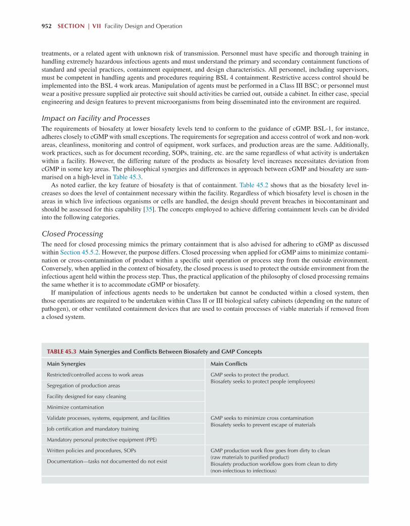
952 SECTION | VII Facility Design and Operation
treatments, or a related agent with unknown risk of transmission. Personnel must have specific and thorough training in handling extremely hazardous infectious agents and must understand the primary and secondary containment functions of standard and special practices, containment equipment, and design characteristics. All personnel, including supervisors, must be competent in handling agents and procedures requiring BSL 4 containment. Restrictive access control should be implemented into the BSL 4 work areas. Manipulation of agents must be performed in a Class III BSC; or personnel must wear a positive pressure supplied air protective suit should activities be carried out, outside a cabinet. In either case, special engineering and design features to prevent microorganisms from being disseminated into the environment are required.
Impact on Facility and ProcessesThe requirements of biosafety at lower biosafety levels tend to conform to the guidance of cGMP. BSL-1, for instance, adheres closely to cGMP with small exceptions. The requirements for segregation and access control of work and non-work areas, cleanliness, monitoring and control of equipment, work surfaces, and production areas are the same. Additionally, work practices, such as for document recording, SOPs, training, etc. are the same regardless of what activity is undertaken within a facility. However, the differing nature of the products as biosafety level increases necessitates deviation from cGMP in some key areas. The philosophical synergies and differences in approach between cGMP and biosafety are sum-marised on a high-level in Table 45.3.
As noted earlier, the key feature of biosafety is that of containment. Table 45.2 shows that as the biosafety level in-creases so does the level of containment necessary within the facility. Regardless of which biosafety level is chosen in the areas in which live infectious organisms or cells are handled, the design should prevent breaches in biocontaminant and should be assessed for this capability [35]. The concepts employed to achieve differing containment levels can be divided into the following categories.
Closed ProcessingThe need for closed processing mimics the primary containment that is also advised for adhering to cGMP as discussed within Section 45.5.2. However, the purpose differs. Closed processing when applied for cGMP aims to minimize contami-nation or cross-contamination of product within a specific unit operation or process step from the outside environment. Conversely, when applied in the context of biosafety, the closed process is used to protect the outside environment from the infectious agent held within the process step. Thus, the practical application of the philosophy of closed processing remains the same whether it is to accommodate cGMP or biosafety.
If manipulation of infectious agents needs to be undertaken but cannot be conducted within a closed system, then those operations are required to be undertaken within Class II or III biological safety cabinets (depending on the nature of pathogen), or other ventilated containment devices that are used to contain processes of viable materials if removed from a closed system.
TABLE 45.3 Main Synergies and Conflicts Between Biosafety and GMP Concepts
Main Synergies Main Conflicts
Restricted/controlled access to work areas GMP seeks to protect the product.Biosafety seeks to protect people (employees)
Segregation of production areas
Facility designed for easy cleaning
Minimize contamination
Validate processes, systems, equipment, and facilities GMP seeks to minimize cross contaminationBiosafety seeks to prevent escape of materials
Job certification and mandatory training
Mandatory personal protective equipment (PPE)
Written policies and procedures, SOPs GMP production work flow goes from dirty to clean (raw materials to purified product)Biosafety production workflow goes from clean to dirty (non-infectious to infectious)
Documentation—tasks not documented do not exist

Facility Design and Process Utilities Chapter | 45 953
Segregation of Infectious and non-Infectious AreasIn GMP operations, the production flow goes from dirty to clean. Raw materials entering the facility are considered dirty. The process includes several steps of purification and inactivation, which means the product becomes increasingly “clean” during the final steps of the process. Within processes that require biosafety, the production flow is opposite to that of GMP production (i.e., clean to dirty or non-infectious to infectious). In this latter case, the production process usually begins with propagation of a cell culture, which is then inoculated with virus. Toward the end of the process, the product is inactivated (or not, in the case of attenuated products). Toxoid from toxin-producing bacteria is obtained in approximately the same manner (i.e., the bacteria is inactivated toward the end of the process). It is important, therefore, that areas containing infec-tious material are kept separate from areas where non-infectious operations are undertaken. BSL guidance need only be implemented within areas where the relevant infectious organisms are being processed, and not throughout the facility. In this way, a complete physical segregation between infectious and non-infectious areas can be achieved. Fig. 45.9 shows a schematic layout of the segregation of active (infectious) and inactive (non-infectious areas). Correspondingly, it is typical for facilities adhering to BSL 2 or higher to implement a uni-directional flow philosophy to ensure there is no crossing of infectious and non-infectious flows. Ultimately the aim is to prevent cross-contamination as with cGMP; however, the intent is moreover to contain infectious areas as much as possible and separate them from the rest of the facility.
Air FlowAs discussed within paragraph 45.5.2, work rooms within the production area are stringently maintained under positive pressure relative to their surrounding corridors and areas. This allows the airflow to move out from the room into the cor-ridor, preventing ingress from outside the room. Conversely, under the guidelines for biosafety, it is recommended that rooms be maintained at an absolute or relative negative pressure to the surrounding corridors and rooms to ensure airflow moves inward. If there are multiple infectious areas, the area of highest potential contamination is the most negative. This is to ensure that any particles emanating from operations within the room are contained within that work area and do not exit, as well as ensuring that the infectious area is supplied with clean (non/less-infectious) areas of the facility.
In the case of GMP operations, air-lock doors should open toward the area of higher pressure. However, from a biosafety point of view, all doors should open toward the largest room of the two, as this will create the smallest amount of air tur-bulence when doors are opened and closed. From a basic safety point of view, it is preferred that a door will not swing out into a corridor where people are expected to pass. From an emergency point of view, however, doors should always open away from areas where hazardous situations might occur [36].
FIG. 45.9 Example layout showing a facility designed for biosafety level (BSL) 2 production. The red-lined area is classified as the contained, infectious area. Processing contained within this area is prior to inactivation. Green and Orange areas of the facility outside the red line area are considered nonactive. Green areas are classified as Grade D environments, Orange area are in Grade C. Blue areas are CNC areas.

954 SECTION | VII Facility Design and Operation
In addition to the airflow directions, the HVAC system is also configured to run in a way to help with the containment philosophy of biosafety. For higher biosafety levels, a single-pass strategy (see Section 45.5.3) is employed, meaning that exhaust air from active rooms is not re-circulated to any other area in the facility, and is discharged to the outside either through HEPA filters or other treatments that prevent the release of viable microorganisms. If no treatment of exhaust air is employed, the discharge point of the air from the facility requires careful positioning to ensure that there is no impact on the surrounding environment.
In some cases, it is necessary to have a dedicated air supply system for the infectious portions of the facility to ensure no cross-contamination of air with that supplied to non-infectious rooms. If the supply system is not dedicated, then it must contain HEPA filters or appropriate dampers, which can protect the system from potential backflow in the event of a system failure. Typically, the supply and exhaust systems for the facility are interlocked to prevent the room pressure from becom-ing positive in the event of power or equipment failure. As is the case with GMP, the systems should be alarmed to indicate system failures or changes in desired air flow; emergency power supply systems are frequently designed this way as well.
Application of Differing Guidelines—Reconciling GMPs and BiosafetyMerging GMP and biosafety containment aspects necessitates a strategy. As in all strategic planning, it is necessary to read all the pertinent guidelines to ensure you and those you will partner with understand them fully. Understanding “why” the guidelines and requirements differ is as important as understanding “how” they differ. Alternate solutions to achieving a goal should be considered and discussed. One way to start is by reviewing the construction of similar facilities to learn how the issues were resolved in those cases. Generally, at low bio-risk, GMP should take precedence. At higher bio-risk, biosafety should take precedence in the design.
Risk assessment is a valuable tool in providing weighted values where there are contradictions between biosafety and GMP guidelines. Several aspects must be taken into consideration while trying to establish the level of hazard associated with an agent. The following factors should be addressed in a risk assessment and thoroughly evaluated: volume, concentra-tion, possible ways of escape, route of transmission, infectious dose, susceptible hosts, incubation period, decontamination and whether immunization or treatment exists. It is important to remember that this part of the risk assessment is a subset of the total risk assessment that must be performed. For a large-scale production of biologicals, it is also relevant to perform a risk assessment on the mechanical performance of various production equipment and utilities. This part of the risk assess-ment highlights the riskiest areas of production by examining various possible scenarios.
45.6 MULTIPRODUCT MANUFACTURING
Instead of the huge, 10-ton, or even higher, annual production scale facilities for one single biopharmaceutical product, it seems more likely that many current and most future facilities regularly must produce more than one product. In other words, the large batch sizes offered by high product titres in the upstream process will be exploited to make needed quanti-ties in fewer batches, liberating production capacity for additional products. Multiproduct facilities are fully accepted from a regulatory perspective now, but they do require several precautions, and are certainly more complex than single-product manufacturing facilities.
The key issue in multiproduct manufacture is how the combination of facility, equipment design, and operational proce-dures ensures the segregation of products. For facilities with multiple products or processes, a risk assessment should be per-formed on the impact of potential process/product failures on other operations in the facility. This analysis should include an established plan of action for different failure modes. Other considerations include different processing/product systems that cannot be opened to the environment within the same production area unless appropriate protective controls are in place. For example, cell culture with similar strains in the same processing area may require a means of strain differentiation (e.g., anti-biotic marking). Given this, generally, in biopharmaceutical facilities, multiproduct manufacturing is undertaken in two ways:
1. Concurrent processing—independent and segregated production suites utilized for the manufacture of different prod-ucts in dedicated unit operations.
2. Campaigned processing—different products are scheduled to be manufactured at different points in time within the same production suite.
As such, the options represent physical and temporal segregation, respectively (1.5.2). Concurrent processing typically involves the use of dedicated unit operations within separate process trains. Each process train is devoted to a product. Essentially it amounts to dedicated, single-product facilities sharing utility and support systems (e.g., media and buffer preparation, column packing, etc.). Although these facilities are large and expensive, they do allow for high productivity, as there is no break in production or downtime necessary for the manufacture of different products.

Facility Design and Process Utilities Chapter | 45 955
Campaigned processing is more space- and cost-efficient, as one suite, and usually most process equipment will be shared among the manufacture of different products. The focus is to avoid cross-contamination through cleaning validation, and changeover procedures between products and production line clearance. In general, the more the products are segre-gated by time and space, the lower the burden placed on procedural control systems. The closer the products are in time and space, the greater the burden of reliance on procedural controls. Spatial and temporal segregation are more robust than procedural segregation methods. In all cases, the guiding principle is to ensure the quality and safety or products.
With appropriate validation of clearance, it should be possible to process a wide variety of biopharmaceutical products within the same facility. Clearance is demonstrated by the removal of product, components, and waste residues from pro-cess equipment. Rigorous cleaning and sterilization procedures must be recorded using a well-established and sound docu-mentation trail. The clearance procedures should be thoroughly tested to provide for the removal of potential contamination sources. Cleaning endpoints must be established. In most cases, it is appropriate to use scientific rationale rather than the limits of detection (e.g., quality by design approaches).
In multi-product operations, it is important to consider the trade-off between cleaning costs (which include changeover, validation, routine cleaning activities and materials, and routine monitoring for cleaning effectiveness) and the cost of dedicated equipment. Typically, chromatography resins and filtration membranes should be dedicated to products because they are notoriously difficult to clean. Similarly, gaskets, O-rings, valve diaphragms, and other “soft” components subject to product build-up are often replaced between campaigns. Due to this, some manufacturers may feel it is more efficient to maintain dedicated chromatography columns between products as well as resins to avoid the time requirements of unpack-ing, cleaning, and repacking columns. It is common practice to physically segregate the cell bank and final bulk product from other products. Other components are typically segregated by means of procedural control as a method of secondary segregation.
A campaigned multiproduct operation is essentially a chronological segregation method. During campaign process-ing, a production year is typically broken up into multiple “campaigns” comprised of several batches of manufacture for a product to meet a specified demand. After a product campaign is completed, a changeover procedure is undertaken, where equipment, and sometimes rooms, are thoroughly cleaned, HEPA filters within rooms are exchanged, and process equip-ment is sometimes reconfigured to, and set up for, the new product to be manufactured. Where a company operates with a well-developed technology platform and focuses on the corresponding category of drug substance, one may aim for several days for change over activity. It helps if different processes do not have unusual unit operations, giving rise to the need for new equipment as part of the change-over, which can lead to increased technical and operational risk. However, change-over time can vary a lot with experience and with homogeneity of the portfolio to be manufactured: 2–6 weeks’ time may be the time range to consider if this is the case [37].
It should be noted, however, that the clear majority of multi-product manufacturing facilities produce products of a specific class (e.g., MAbs or rProteins), or those which are derived from the same expression system (e.g., mammalian or microbial cells). The threat or perceived threat of cross-contamination is considered too high to campaign products emanating from different expression systems within the same production area. It is unlikely, for instance, that live vaccine manufacturing takes place in the same building as monoclonal antibody production.
The intended purpose of the facility will also factor in the decision making for how the facility layout will look. For ex-ample, a cGMP development operation usually requires flexibility to adequately perform its intended function. Such facili-ties usually have layouts that allow for different personnel, materials, and equipment movements, since the unit operations required by each product under development varies. To meet the requirements of the regulations for no cross-contamination of products, and to prevent the mixing of various components or product intermediates, the procedures used during the operations delineate the guards against such results, rather than the solution being built into the physical facility. In this case, conservative pragmatism may prevail with a facility design more in line with a uni-directional philosophy to mitigate concerns of cross-contamination.
However, a large-scale manufacturing facility producing commercial products usually does not require the same level of flexibility as a small one. The facility is usually dedicated to products requiring the same or similar unit operations and thus the physical facility arrangement can control flow patterns. Under this arrangement, the physical facility provides operational flexibility. Operating procedures would be in place to ensure that products and intermediates are not mixed and cross-contamination has been prevented. The balance between the use of physical barriers or procedural barriers needs to be discussed with the operating unit and the quality unit prior to finalization of the conceptual design. In the case of contract manufacturers, their systems must reassure different clients that cross-contamination did not occur without releas-ing confidential information. The development and execution of extensive cleaning validation procedures will be central to evidence-driven declarations. Such reassurance is often difficult, but needs to be ensured by the owner of the product/application.

956 SECTION | VII Facility Design and Operation
45.6.1 Considerations for Flexible Facility Design
As discussed, designing a facility agile enough to accommodate several manufacturing scenarios is innately favorable com-pared with single-product dedicated facilities. The caveat here is that no manufacturing scenarios within the facility should compromise regulatory agency guidelines or biosafety constraints of the facility.
Facility agility, or “flexibility,” is often related to multi-product processing and scalability. In terms of the facility de-sign, this can be captured in four basic levels [38]:
1. Process flexibility. This accounts for production mode (batch, fed-batch, perfusion, etc.), unit operation configuration, and volumes.
2. Production area flexibility. Process suite configuration to accommodate the process flexibility such that future options can be exercised with minimum intervention to facility structure.
3. Retro-fitting into existing infrastructure. New capacity may need to integrate into an existing site master plan or build-ing and must reserve options for future expansion. This can lead to an evaluation of unit operation technology to be considered, or construction methods.
Processing flexibility is often used in conjunction with single-use equipment technologies. Targeted application of such technol-ogy introduces design flexibility through various options that can rapidly reconfigure a process sequence and scale after a project definition is established (something that is very challenging with stainless steel configurations). Stainless steel unit operations and vessels (depending on scale) tend to be fixed installations within the facility. Furthermore, piping distribution networks are innately fixed and limited to the transfer panel options pre-determined during the design phase. Any changes to this configuration, for instance to satisfy the requirements for a different product, would require some construction work and re-validation activities. This is not to say that such a solution is impossible in a stainless steel environment. Large CMOs tend to have to carry out minor to medium facility infrastructural changes to satisfy the needs of new products from different clients.
Single-use technology, however, brings about an ease of operational flexibility by simply renewing the product-contact lining of manufacturing equipment [38]. Systems are smaller and the majority of them are mobile. This technology addresses cGMP clean-ing and carryover concerns and allows for agility with rapid start-up and changeovers for a given product portfolio. Since the reliance on fixed infrastructure, such as CIP/ SIP systems, is reduced, there is more scope for equipment reconfiguration to meet dif-ferent process needs. It should be noted, however, that although piping networks are reduced in a single-use dominant facility, they are certainly not eradicated. WFI and process gas supply will still be required, and as a result, location of specific equipment (e.g., bioreactors or preparation mixing vessels) will be determined by the point-of-use taps within the distribution network of each utility.
Foresight of the level of flexibility required by a facility during the front-end engineering design phases (Section 45.9.1) will ensure the correct facility design to accommodate the best GMP design.
“Ballroom” versus SegregationWithin the manufacturing facility, flexibility is required for the shrewd use of the production space for process operations, reserved workflow routes, and readiness for room classification changes to accommodate the different needs of different products and their associated processes. Recent thinking within the industry has promoted the use of a “ballroom concept” for the layout of biopharmaceutical bulk biologics facilities. The definition of the ballroom concept is “a large manufactur-ing area that has no fixed equipment and minimal segregation due to the use of functionally closed systems” [39]. In the ideal case, the use of the ballroom would result in a totally open product space where media preparation and buffer prepara-tion, and USP and DSP operations would all take place in the same room. Fig. 45.10 shows what this ideal state may look like in terms of production layout. The ultimate degree of flexibility that is achievable through single-use technology is through this open-architecture “ballroom” type design and operation that house an entire process train in one or few process rooms. However, this concept requires that a process be fully closed — a challenge that typically is possible only with a single-use setup.
The rationale behind such an idea, however, is based on the cost savings one can incur together with the flexibility of operation possible. Open-architecture designs improve core facility space use and are more amenable to repurposing func-tional areas for newer processes and production volumes. A large open area where all skids are on wheels allows for rapid reconfiguration of the facility, easy cleaning, and fast construction. By removing levels of segregation, total area needed for manufacturing is reduced as walls and doorways are removed. This becomes quite attractive when running a predominantly single-use process where the logistical needs of transporting various components to and from storage or warehouse areas becomes important. Furthermore, if one deems that equipment is run in totally closed systems, then surrounding areas can

Facility Design and Process Utilities Chapter | 45 957
be re-classified as compared with the standard way of thinking. Reducing the classification level (e.g., from Class C to Class D) already has huge potential for savings in HVAC running costs, not to mention further space reductions owing to the reduction in the number of airlocks needed to bridge different classification levels. These impacts can have a profound impact on the CAPEX and OPEX of the facility. Probst et al. [40] even extend this notion to argue that using risk assess-ment and the highest operational procedural discipline, concurrent processing utilising closed systems could be achieved in the same open architecture room.
Alternative strategies, however, may be required, depending on the type of multi-products being considered for manu-facture within the same facility. For instance, where processes for different products are platform, foresight of design can typically account for the most flexibility needed within a facility. However, in cases where a platform process cannot be utilized to product manufacture, a different approach may be undertaken. The example typically cited is that of vaccine manufacture. Vaccines can be produced through a variety of methods (see Chapters 2 and 43). Segregation and biocontain-ment tends to be based on live virus inactivation. In the case of a live attenuated vaccine, where no inactivation takes place, containment may be necessary for the entire production train. The point of viral inactivation (should it take place) could be different for different vaccines groups. A ballroom-type concept, in this case, would be useless, as the segregation strategy could be different for different processes. A flexible facility design solution, therefore, could mean an increase in physical segregation using multiple, separated processing suites, potentially with dedicated HVAC systems. Despite the increases in complexity and costs, this may allow processing of different configurations of equipment within different process suites to adhere to the requirements of different processes. Extensive risk assessment would need to be undertaken to validate such an approach; however, the facility would, in fact, allow for more product processing flexibility than a ballroom.
The other part of facility flexibility, scalability, means that processes and the facility are required to “pulse” with the capacity demands needed. The facility needs to be able to ramp-up fast, if the drug demand is increasing, and as easily ramp-down, if the demands are reduced. That does not mean that the production processes are out of control, they are just processing different demands of drug product at the same quality. Therefore, the process and surrounding environment requires robustness, and the ability to be duplicated. Again, in this case, having equipment that can be mobilized, and delin-eated from the facility, will better facilitate increasing and decreasing production demands as necessary.
45.7 PROCESS SUPPORT FUNCTIONAL CONSIDERATIONS
Although the production process is the main concern of the manufacturing facility design, it will be unable to operate without the help of the supportive functions that allow manufacture to take place and cGMP to be followed. The following sections seek to outline the different functional needs to be considered in the overall facility design.
Media
Inoc.prep
Pre-viralD.S.P.
Offices
Cleanutilities
Plantutilities
(A) (B)
Plant utilities
Post-viralD.S.P.
Post-viralD.S.P.
Wash
C.I.P./S.I.P.
Equip.prep
Pre-viralD.S.P.
Cellculture
Cellculture
Inoc.prep
Lockers/gowning
Offices
Lockers/gowningLabs Labs
WarehouseWarehouse
BufferMedia Buffer
FIG. 45.10 (A) A traditional segregated layout scheme for MAb processing for two lines. (B) An equivalent ballroom layout for two production lines. An assumed closed processing approach allows for minimal to no segregation needs.

958 SECTION | VII Facility Design and Operation
45.7.1 Fluid Transfer
The routing and directing of fluid transfers within a manufacturing facility represents a significant cost in terms of stainless steel piping, transfer panels, and valve arrays. Transfer systems for use with media, buffers, culture, harvest, or in-process materials may be designed around portable vessels, transfer panels, or dedicated transfer lines. CIP is usually routed using fixed CIP supply and CIP return lines that are piped to the various pieces of equipment and transfer panels. The CIP supply and return systems can be very complicated in large-scale manufacturing.
Flexibility inside a facility can be realized by keeping the connections between different process steps flexible, which is achievable with both fixed piping as well as flexible hose connections. The main disadvantages of fixed piping are [41]:
● Each potential combination of the equipment should be anticipated and connected up front.● The cleaning of the closed equipment means significant additional piping for cleaning liquids and steam supply; more-
over, cleaning validation can be laborious.● Cross-contamination should be avoided by complex valve configurations. These significant drawbacks have resulted in
the fact that many biotechnological facilities are not hard piped, but use flexible connections between the apparatus.
Two fundamental approaches may be taken—transfer panels with U-bends, or fixed valve arrays [22]. There are advan-tages to both, but the costs may not be that substantially different when installed. Transfer panels are operator-intensive, while valve arrays are automation intensive. When transfer panels handle dangerous materials or pressurized contents, they should be equipped with proximity switches and be tied into a control system that only allows transfers of CIP solutions on a permissive basis after an allowable flow path has been configured. In addition, lines should be equipped with pressure gauges and bleed valves to allow depressurization of lines prior to loosening of clamped nozzle caps.
For small-scale operations or in single-use predominant processes, in-process materials, or cultures, are generally man-ually transferred in bags between operation steps or through a combination of flexible tubing, peristaltic pumps, and aseptic connections. When transferring materials in portable vessels or bags, pass-through between adjacent process rooms is pre-ferred as a means to improve the material flows through the facility. Without pass-through between adjacent process rooms, the intermediate product in a portable vessel or bag would need to exit to a corridor and enter the next processing suite.
Solutions are usually transferred by overpressure wherever possible, to eliminate a potential contamination source from pump seals, as well as simplifying the design, which reduces initial cost and ongoing maintenance (by eliminating the pump), and reduce potential shear damage to the product or organism. Hygienic design and cleanability of process piping systems are considered essential for the production of bioengineered pharmaceutical products. Process piping lines are sloped for drainability as gravity is the most efficient means of draining fluid from a system. Limits on inside diameter (ID) and outside diameter (OD) concavity and misalignment are set to promote drainability and cleanability of weld surfaces.
Cleanability and design are not only limited to piping, but to all process vessel. Requirements have been established by the American Society for Mechanical Engineers, Bioprocessing Equipment guide (ASME-BPE) [42], which outlines the requirements of the bioprocessing and pharmaceutical industries, as well as other applications with relatively high levels of hygienic requirements or bioburden control. The BPE covers directly or indirectly the subjects of design of process equipment for cleanability and sterility, component manufacture, materials of construction, fabrication including welding, pressure systems (vessels and piping), examinations, inspections, and testing and certifications.
45.7.2 Cleaning and Sterilizing Systems
As discussed previously, single-use systems have, in the last decade, become a fully accepted component in biopharma-ceutical production [43]. Their uptake has been predominantly in the use of buffer and cell culture media hold vessels, as well as for the growth of animal cell culture. However, their application is limited by scale, and in some cases, maturity of technology. Thus, traditional stainless steel vessels and piping represent the proven alternative to any “gaps” in the single-use portfolio. The drawback, however, is that the use of product contacting steel surfaces requires rigorous, well defined, and reproducible cleaning in between batches. Reproducible cleaning of product contacting surfaces is critical to prevent contamination of product that could alter its safety, identity, strength, quality, or purity [23]. Any residue of previous pro-duction batch is to be washed away completely to avoid cross-contamination.
Generally, biopharmaceutical processes primarily employ aqueous-based cleaning, using alkaline and acid solutions to remove the “soil” or contaminants, returning the equipment to its original use condition [44]. Equipment cleaning regimes are batch-wise in nature, where a defined sequence of steps or phases are undertaken within a particular cycle. A CIP cycle is made of one or multiple phases, described as follows:

Facility Design and Process Utilities Chapter | 45 959
Rinse PhaseRinse water, or solution, is supplied from the CIP unit, and this phase is used to flush the CIP circuit of all free rinsing soil and chemical solutions to waste. The rinse phase may be repeated multiple times during a CIP program as a pre-flush prior to a chemical wash, or after a chemical wash as a post-wash rinse. Although most rinse phases are performed with water, the rinse may also be performed with a base, acid, saline, or solvent solution.
The most common application of a rinse solution is high quality water, but not necessarily the highest quality water in the facility [45]. If there are two water qualities available in the facility, the lesser quality water may be suitable for the rinse and chemical wash phases, with the process quality water being used in the final rinse phase, thus reducing production cost of high quality water in the facility. Typically, purified water is used within the rinse steps, with WFI utilised for the final rinse. The recipe set point for the rinse temperature may require adjustment, heated or cooled, to tailor the phase to the cleaning needs. For example, a heated post-rinse is desirable to improve the solubility of alkaline solutions, reducing the rinse volume required to remove the spent solution.
Gas Blow PhaseThis phase uses compressed, filtered gas to clear the CIP supply and process piping to the process equipment being cleaned to enhance a clear transition between dissimilar phases, when necessary.
The gas used is filtered process air. or nitrogen for systems that require an inert atmosphere. A gas blow pressure release step is always included in the phase to allow the gas pressure to dissipate prior to continuing with the CIP program. An intermediate drain phase always follows a gas blow phase to discharge the solution to be blown into a vessel for transfer to waste handling.
Intermediate Drain PhaseAn intermediate drain phase is used between CIP phases to actively transfer spent wash and rinse solutions from the circuit boundary to enhance a clear transition between dissimilar phases. The objective is to remove previous rinse or wash solu-tions from the circuit prior to introducing the next solution. An intermediate drain is recommended after a rinse or chemical wash phase to ensure a clear separation between the previous solution and fresh wash or rinse solution to be supplied.
Chemical Wash PhaseThis phase performs the chemical cleaning duty and may be either a single pass through the circuit to waste, or recirculated through the CIP circuit. The chemical wash may be an alkaline or acid solution in aqueous cleaning programs.
The objective of the chemical wash phase is to expose all equipment surfaces within the cleaning boundary to the required physical action, time of exposure at cleaning temperature and chemical concentration to dissolve, suspend, and remove the product soil.
Chemical Selection
The required cleaning chemistry is dependent on the nature of the soil to be removed. For example, if the soil is primarily a biological material made up of carbohydrates, protein, and fat, then an alkaline-based cleaner is suitable for the primary chemical wash phase. However, if the soil load is primarily protein in nature, a hot acid wash may best serve the needs of the equipment to be cleaned.
Commonly used cleaning chemicals include caustic soda, phosphoric and nitric acids, sodium hypochlorite (Hypo), and peracetic acid (PAA). Caustic soda is an alkali typically used at 0.5%–2% volume. It reacts with the fats in the soil and softens it for removal. One downside is that caustic soda is not effective for removing scaling. Phosphoric and nitric acids are used in detergent formulations for scale removal, often at lower temperatures than caustic. These acids must be used with care as they can attack valve and pump seals.
Common CIP chemical solutions are commercially available, for example, CIP 100 (alkaline detergent) and CIP 200 (acid detergent) (Steris Life Sciences), which are typically the first recourse for testing suitability for cleaning.
A detailed discussion on cleaning in place and sanitization procedures and chemicals for use with chromatography and filtration steps can be found in Chapter 33.
Final Rinse PhaseThe final rinse is performed with the highest quality water available within the facility, meeting the quality of water used for process operations (usually WFI). The objective of the final rinse phase is to flush all equipment surfaces within the

960 SECTION | VII Facility Design and Operation
cleaning boundary free of all product soil and residual chemical wash solution. The final rinse water should be specified in the User Requirements as either: (i) the highest quality water available in the facility or (ii) the water quality equivalent to that specified for process operation. The termination point for the flush is typically based on CIP return conductivity or resistivity monitoring, or based on supply of a flush volume validated to achieve the required results.
Final Drain Phase (Gravity)This phase begins by opening all drain valves, with CIP return pumps and equipment gas blanketing “off,” providing for gravity drainage to and from all CIP circuit low points.
The final drain removes, via gravity, the residual rinse at CIP circuit low-point drains prior to concluding the CIP Program. As there are differences in the function, there are also device-positioning differences in the intermediate and final drain. The intermediate drain uses some form of motive force (pumping, gravity, educator assist, or some combination thereof) to actively direct the solutions to waste. The final drain opens all low-point drain valves, and gravity drains off the minimal residual amount of final rinse water or solvent.
The make-up of the CIP cycle must be determined on a case by case basis to be customized for the specific surface soils that need to be cleaned.
Given the complexity of the cleaning cycle, it is challenging to clean unit operations within a biopharmaceutical process without the use of automated systems. CIP systems generally require the use of in-place process fluid pumping systems and may impose additional complex operating (switching) procedures on the process unit operation. Such pumping systems are known as CIP skids.
The volume of water and chemical solutions required for the different phases within the cycle is a matter for develop-ment through small- and pilot-scale studies. The ASME provides guidance that flow of cleaning fluid must always be in the turbulent regime and so must be at least 5 ft./sec. within piping. Similar fluxes can be attained for pressure vessels depending on their design [46]. Required contact times, whether through single-pass or recirculation operation, should be determined through experimentation with the specific soils that require cleaning.
CIP skids can be made up of single tank or multi-tank systems. The tank or tanks within the skid are for holding and recirculating the different water and chemical rinses required as described herein. In a centralized system as shown in Fig. 45.11, the CIP skid would be connected to the unit operations that require cleaning via stainless steel piping. A central skid will likely support multiple unit operations, and as a result, a transfer panel is typically used to direct flow to the ap-propriate unit operation needing cleaning. Independent CIP piping is provided to the unit operation for the supply of the cleaning solution as well as a return line back to the CIP skid. Fig. 45.11 shows only a schematized version of the piping network of a central CIP solution. In reality, the pipe network could be quite complicated, as not only is the unit operation
PRE-RINSE
PRE-RINSE
PRE-RINSEActivewaste
Activewaste
Activewaste
Pre-rinse (collecting offinal rinse)
Final rinse (break tank)
Activewaste
Inactivewaste
Unit operations to be cleaned Transfer panel Centralised CIP system
PW PWConc
alkaline dose
PW
Conc acid dose
WFI
CIP program / cycle steps:
1. PW prerinse—drain at user point 2. Alkaline recylce cleaning - drain at CIP skid 3. PW rinse—drain at CIP skid 4. Acid recycle cleaning - drain at CIP skid 5. PW flush—drain at CIP skid 6. WFI final rinse—drain at CIP skid / collect 5. Clean compressed air blow out
AcidSolution
(if needed)
Alkalinesolution
FIG. 45.11 Schematic showing a possible configuration for a centralised multi-tank CIP system within a facility: where, PW-Purified water; WFI-Water for Injection

Facility Design and Process Utilities Chapter | 45 961
being cleaned, but also it is common to clean its product and clean utility transfer lines at the same time. Therefore, valves and additional pipe work may need to be added around the system to attain this goal.
Fig. 45.11 also indicates a sample cleaning cycle comprising the cleaning phases as described herein. A multi-tank CIP skid may be fitted with one or more water tanks to accommodate the different water qualities or temperatures. For instance, in this example, a separate tank is provided for purified water (PW) and water for injection (WFI, see Section 45.7.4 for definitions for water types). Independent tanks are also shown for storage and distribution of the chemical phases. On initia-tion of the cleaning procedure, purified water from the main facility distribution loop will start to fill the PW tank of the CIP skid. Once the appropriate volume is filled, the CIP skid will pump this PW to start the pre-rinse phase of the cleaning cycle for the appropriate unit operation. Once this is completed, alkaline rinsing can start, the filling of which, at the CIP skid, would have already been initiated during the pre-rinse. Chemicals are usually provided in concentrated form and dosed into the appropriate chemical recirculation tank and diluted in situ. Once ready for transfer, the chemical rinsing can be initiated. This is continued for the different chemical and water rinse steps until the full CIP cycle is completed.
Typically, the CIP program utilises both single-pass rinse phases, particularly for the initial pre-rinse, but recirculates chemical wash solutions between the CIP unit and the equipment being cleaned, permitting an extended chemical wash ex-posure, while minimizing water, heat, and chemical cost [45], and the waste volumes discharged for treatment. Single-pass CIP systems require significantly more water and chemical, and therefore a greater capacity for waste handling. Despite the utility burden, a single-pass CIP program may be desirable in some circumstances. Multi-product facilities may elect to use single-pass CIP to avoid extensive validation to prove no cross-contamination of dissimilar product through the CIP system. Single-pass rinses are generally utilised for pre-rinse steps, as this is the stage where the equipment is at its most soiled. It would be counter-intuitive to continuously expose the soil to the equipment surface through recirculation. At the same time, increasing the contact time of chemical solutions to the equipment surface through recirculation would increase the cleaning while conserving water solutions. A common conservation method adopted during the cleaning cycle is the collection of a portion of the final WFI rinse volume within the pre-rinse PW tank. This can then be utilized as the pre-rinse for the next cleaning cycle of the unit operation.
Use of centralised CIP equipment can optimise its utilization and therefore help minimise costs. Centrally located sys-tems can also help minimise installation and operational costs for critical utilities feeding the cleaning system. However, these systems are complex and are only beneficial when they can support the cleaning of multiple large-volume unit opera-tions within the facility.
In the cases where only a few unit operations are stainless steel or equipment volumes are quite small, then CIP systems can be dedicated to a unit operation, or a mobile CIP skid may be utilized. Fig. 45.12 shows an example of a mobile CIP skid. Dedicated and mobile CIP skids tend to comprise a single (or at the most two) recirculation tank(s). A single-tank skid would require the provision of the water supply to the CIP recirculation tank. The water supply connection could come from two different tap points for PW/WFI. The smaller skid is typically attached to the unit operation being cleaned via flexible transfer tubes. The recirculation tank would be filled with the appropriate volume of water from the PW/WFI distribution loop and heated to the correct temperature before being applied to the unit operation. Chemical dosing could be undertaken for the chemical wash phases. However, the disadvantage of the single-tank skid is that time is lost as the tank is drained and filled in a series during the cleaning cycle. The provision of one extra tank can mitigate this, so that solutions for successive rinses can be prepared while the current phase is ongoing.
Prerinse Activewaste
Unit operation to be cleanedMobile cip skid
Inactivewaste
Concalkaline dose
Conc acid dose
PW/WFI
FIG. 45.12 Schematic of a possible setup for a mobile CIP skid.

962 SECTION | VII Facility Design and Operation
Cleaning equipment and associated transfer piping are inherently self-cleaning and their cycles should be validated, es-pecially those systems that are centralised and shared between numerous unit operations or functional areas. The cleanabil-ity characteristics of the CIP system itself are therefore just as important as with process equipment. Cleaning regimens will be most critical for shared CIP systems serving multi-product operations. Increasing the number of equipment cleaning cycles may be necessary to provide assurance that all contaminants have been removed. Operations downtime from addi-tional cleaning cycles may justify the use of segregated CIP systems.
Ancillary Equipment CleaningSoiled equipment such as flasks, bottles, tanks, and glassware must be cleaned in a validated fashion as well. The first choice is often to use disposable items wherever possible. Beyond this, a choice must be made concerning where to clean the glassware and equipment—either at a centralized equipment wash area, or in a distributed fashion within the suites where the glassware or equipment is used. Washing can be performed manually following defined cleaning steps (such as those in a cleaning cycle), via soaking, or more automated techniques such as the use of a parts washer. Although an automated system has clear benefits, parts washers are notoriously difficult to validate from the cleaning perspective. In some cases, wash areas could also use a fixed CIP skid that could be used to clean smaller mobile SS tanks or vessels (<250 L) that are too large for a parts washer, but too small for cleaning via a centralized system. These vessels are deemed to be cleaned out of place (COP).
Glassware and equipment wash areas are preferably organized around a flow from dirty to clean to sterile, as shown in Fig. 45.13. Generally, this is achieved by organizing the glassware and equipment wash suite, with a staging and dirty wash area, an area for the wrapping and assembly of clean glassware and equipment and loading into the sterilizing autoclave, and an area where the autoclaves are unloaded into a separate room.
The autoclave unload area generally has a HEPA filter area above the unload zone of the autoclave. It is important to provide for adequate staging space for the dirty glassware, carts, and equipment. Ideally, double door pass-through washers are used so that only clean glassware and equipment is introduced to the clean assembly area. Where quantities justify, it may be useful to plan for a separate sterile glassware storage room or sterile tank storage room. Sterile glassware and tanks are transported, as required, to the various operating areas.
Equipment from a biocontainment area may require decontamination via SIP or an autoclave (or for lower containment levels, perhaps chemical decontamination) prior to disassembly and cleaning. Decontamination autoclaves for situations other than high containment may be located centrally and adjacent to the dirty wash area. In situations where bags are used for buffer and media, the drums are preferably washed using a large equipment washer with a drying cycle, which unloads in a clean drum storage area. While there is no product contact with the bag holder drums or totes, and they could be manu-ally wiped down, this is very labor-intensive, and not very reproducible. A pass-through from the dirty to the clean side will be required to move any bulk items that cannot be washed nor autoclaved, such as carts.
Cleaning ValidationValidation of the cleaning procedures for process equipment and piping, including chromatography columns, must be performed. This is especially critical for a multi-product facility where carryover cross-contamination is of major concern. Cleaning regimes should remove endotoxins, bacteria, toxic elements, and contaminating proteins while not adversely affecting the performance of the equipment [23]. The cleaning procedure used needs to be validated for effectiveness for each bulk drug substance or intermediate product to which a unit operation is exposed. The burden is on the facility owner to prove that specific residues are reduced to acceptable levels, usually expressed in parts per million (ppm) or parts per
Returncorridor
Washing dirty: dissasmebly and
wash
Autoclave unload
and stagingSupplycorridor
MAL OUT
PAL OUT
Clean assembly
Autoclave
Washer
Soiled equipment inClean equipment out
Room classification
Class C
Class D
5'-1
5/8
"
5'-1
5/8
"
FIG. 45.13 Schematic showing the possible organization of wash area within the facility for small equipment and parts cleaning.

Facility Design and Process Utilities Chapter | 45 963
billion (ppb) quantities. Acceptable limits for reduction are not stipulated by cGMP guidance. The rationale for the residual contaminant limits for each piece of equipment should be scientifically sound and based on the manufacturer’s knowledge of the materials involved and should be designed to be practical, achievable, and reproducible. Essential to CIP validation, as well as routine monitoring, is a robust sampling plan to assure surfaces are cleaned to the acceptable limit. One method is the sampling via swabbing of cleaned surfaces. Alternatively, a sample of the final WFI rinse at the end of a cleaning cycle is also commonly taken for analysis purposes.
Steam in PlaceEnsuring sterility within areas exposed to biologically active systems is critical to preventing cross- contamination between batches and products within the biopharmaceutical facility. Generally, biologically active systems are exposed to equipment during cell culturing and harvest, and as such, CIP operations or chemical sanitization may not be sufficient to ensure the equipment is ready for the next batch. Furthermore, this equipment is much too big to be placed within an autoclave. In this case, sanitization via chemical treatment or sterilization via clean steam is undertaken. Clean steam is used to heat product contacting surfaces up to 121°C and maintain it at that temperature for 15–30 mins. Clean steam is pumped directly into the vessel being sterilized in a heat-up phase that could last for long periods, depending on the size of the vessel. Once the defined temperature has been reached, it is maintained for up to 30 mins. before steam is stopped from the entering the vessel. At this point the vessel is in the final cool-down phase for SIP. Cooling and heat maintenance is facilitated by the jacket around the vessel being sterilized, which can either be supplied with technical (or “plant”) steam or hot water for heating or chilled water to aid with cooling. As with CIP operations, all transfer lines exposed to biologically active material should also be steamed in place. In addition, in these cases vent filters in place on equipment are also sterilized in place together with the unit operation.
The SIP process will inherently introduce liquid condensate into the system during the cycle. Equipment must be de-signed to allow efficient drainability of the steam condensate to prevent any stagnation of contaminated liquid that could cause contamination. The maximum amount of condensate is generated at the SIP start because of the high temperature difference between steam and the heat transfer equipment. Typically, steam traps are a part of the inherent design of an au-tomated SIP system. Steam traps shut automatically once the steam exits the drain and vent valves and indicates that air and condensate have been removed. This limits the steam flow and allows the system to be increased to, and maintained at, the desired sterilization temperature. Steam traps will open intermittently to evacuate condensate and allow replacement with fresh saturated steam. The entire system must be designed to be pressurizable with sterile air during the cool-down cycle to avoid creating a vacuum in the system that would draw in contamination.
45.7.3 Heating Ventilation and Air conditioning (HVAC)
The HVAC system is fundamental to achieving the control of the environmental conditions within the biopharmaceutical facil-ity. This is to provide workers with a comfortable working environment as well as the provision of rooms and the manufacturing process with the necessary level of cleanliness and pressurisation to facilitate cGMP and BSL requirements for manufacturing.
HVAC systems perform four basic functions:
1. Maintain room cleanliness. Control of airborne particles, dust, and micro-organisms is performed through air filtration using high-efficiency particulate air (HEPA) filters.
2. Maintain room pressure (ΔP). Areas that must remain “cleaner” than surrounding areas must be kept under positive pressurization, meaning that air flow must be from the cleaner area toward the adjoining space (through doors or other openings) to reduce the chance of airborne contamination. This is achieved by the HVAC system providing more air into the cleaner space than is mechanically removed from that same space.
3. Maintain space moisture (relative humidity). Humidity is controlled by cooling air to dew point temperatures or by using desiccant humidifiers. Humidity can affect the efficacy and stability of drugs and is sometimes important to ef-fectively mold the tablets. Controlling the moisture content of the environment is also important in minimizing the potential for microbiological growth on clean room surfaces.
4. Maintain space temperature. Temperature can affect production directly by impacting chemical or biochemical reac-tions or indirectly by fostering growth of microbial contaminants in the process or on workers.
General System OverviewFig. 45.14 shows a basic schematic of an HVAC system. HVAC systems are driven by air handling units (AHUs). Conventional air handling units consist of filters, coils, and fans in a metal casing with an insulation liner applied to the inside of the casing.

964 SECTION | VII Facility Design and Operation
Incoming air from outside the building enters the AHU and undergoes filtration through a series of roughing filters. Atmospheric air may contain a mixture of dry particles, fibres, smoke, fumes, and live/dead organisms. The airborne particle size varies from 0.01 μm to 100 μm and their concentration increases strongly closer to the ground. Therefore, AHU units should be placed on rooftops or in enclosures. Roughing filters are designed to capture a significant percentage of the total mass of these particles (30%) down to 20 μm. These can easily be cleaned through washing. The newly filtered incoming air will then be cooled, and in that way, dehumidified. Cooling usually takes place via a cooling coil supplied by either chilled water or glycol supply from the facility central utility system. The cooled air may then be filtered again before being humidified again to meet the room air requirements. Humidification is achieved through steam injection with steam made up from purified water or WFI (see Section 45.7.4). Particularly for supply to clean rooms, there is a trend in using clean steam for humidification to maintain cleanliness levels. In times of low relative humidity, more humidification is needed than in times of high relative humidity.
Following humidification, the air is then heated up to the temperature required for room supply. Heating is achieved through a heating coil that could be supplied by the facility hot water system. The heated air is then discharged from the AHU via a supply fan into the HVAC duct network, which is responsible for distributing air to the rooms that are to be supplied from that dedicated AHU.
Air supply is then directed toward either a constant volume damper (CVD) or variable air volume (VAV) box. In the case of the use of a CVD, the volume of air supplied by the AHU is directed toward a re-heater, allowing for compensation of any temperature variations from the AHU. Temperature and air flow are determined by the specific room requirements and driven from the AHU centrally.
If a variable air volume system is used, the VAV box manipulates both temperature and air volume. If the incoming temperature of the air supplied from the AHU is too high compared with the set point value of the room, the VAV box will first reduce the reheating and increase the air volume. If the temperature is too low, then the air volume is reduced to a minimum and reheating will begin. The variable air volume system can be a more efficient approach because temperature and air volume are more closely attuned to the point of use. However, this should be evaluated against the number of rooms being supplied by an AHU because pressure balancing of rooms could be more of an issue due to the fact that air change variations are more frequent than via a constant volume approach.
Air at the correct temperature and volume is passed through a terminal high-efficiency particulate air (HEPA) filter before being dispersed into the room via a diffuser. Air exits the room via a wall louver, typically located near the floor and recir-culated back via return fans to the AHU. Depending on the approach undertaken (single-pass or recirculation), returned air
Roof
Interstital space forducting
Fresh airin
Airout
Steam
1 2 3
44
5
66
7
Technical levelAHU
Processroom 1
Processroom 2
Processroom 3
Process room 4
8
9
10Manufacturing level
111 Return fan
22
33
44
555
66
77
88
Damper
999
1010
1111Filter train
Cooling
Humidifiaction
Heating
Supply fan
Constant/variable air volume box
HEPA filter
Diffuser
Return booster fan (if needed)
11
FIG. 45.14 General schematic showing the major components of an HVAC system.
Facility Design and Process Utilities Chapter | 45 965
is expelled to the atmosphere or recycled. The quantity of expelled air can either be 100% in a once-through system, or only a certain percentage (typically 20%–30%) for a recirculation system, with fresh air being used to make up the volume lost.
Room CleanlinessAlthough the HVAC system is responsible for the supply and control of the environment for the whole building, there is an emphasis on its design for supply and control of the manufacturing room environments, and particularly the clean rooms. Control and maintenance of room or space cleanliness and environment is an essential principle of cGMP.
Air filtration systems serving the product manufacturing process are designed to enable the control of particulate con-tamination. All air handling systems incorporate some type of air filtration scheme, whether built into the air handling unit, or using terminally installed high-efficiency particulate air (HEPA) filters. Filters are rated for their effectiveness in remov-ing particulates of a nominal diameter of 0.3 μm. The higher the efficiency rating,as a percentage, the more effective the filter is in preventing particulate contamination. Biopharmaceutical facilities commonly use HEPA filters with a minimal rating of 99.997% for critical operating areas.
Most HVAC systems operate on the principle of dilution to control the particulate count within a certain space. This is achieved through manipulation of the air exchange rate within a space. Even though various design guidelines and stan-dards are available [27], there is no clear-cut guidance for air changes per hour. However, there is a common understanding in the pharmaceutical industry, and a regulatory requirement for a minimum air change rate for an area—typically a rate of 20 per hour for classified areas [30] is chosen. This value typically increases with the room classification level: 20–40 air changes (AC)/h for Grade C and 40–60 AC/h for Grade B areas are typical benchmarks [27]. There is no minimum air change rate for non-classified areas, except as defined in local Building Codes (often 4 or 6 per hour), although the WHO guidance for OSD HVAC [47] suggests that a room class, air change rate, and recovery period be established by the facility owner. The European GMP [48] regulations have a requirement for a “clean up” time of 15 to 20 minutes in a sterile product processing facility. It is the resultant particulate level achieved in the various operating states (at-rest and dynamic) that is important and is the determining factor for specifying the air change rate.
In the cases where open processes may be undertaken within a room, certain particle extraction systems or containment systems may be employed and connected to the main facility HVAC. These could include but are not limited to:
Down Flow Booths
Recirculating air down flow booths provide a protection for the operator and environment when the open product will be handled. The down flow air, produced within the booth’s safe work zone area, forces clean air over the operator’s head and shoulders and downward toward the exhaust system at the bottom.
Local Laminar Flow system
In some areas, Cleanliness Class “A” is required. This class can be maintained by recirculating LF-Units only. Types and technical parameters depend on the dedicated application.
Laboratory Exhaust
Within laboratory areas, fume hoods and spot hoods are installed, providing safe working conditions for the personnel han-dling chemical substances. This equipment must be exhausted separately from that of the room exhaust.
The AHUs should be located on a separate equipment floor or zone to facilitate service and maintenance without dis-turbance to the aseptic/sterile manufacturing environment. Also, the location of outdoor air-inlet louvers must be carefully considered. Intakes should be located on the building sidewall high off the ground to minimize dust intake. Intakes should be away from truck docks or parking lots where undesirable fumes and particulates are generated. Location should also consider the prevailing winds and any nearby exhausts or fume concentrations to prevent recirculation of exhaust air back into the supply system.
Similarly, the location of the exhaust fans will require some consideration. Building exhausts are generally collected and ducted to exhaust fans in groups or clusters. Exhaust fans should be located as near to the building discharge as possible because this keeps the duct under a negative pressure and any leaks will be into the duct and not contaminated air from the duct into an occupied space or mechanical room. For this reason, roof locations of fans are preferred, even though this may make service difficult in severe weather conditions. When fans are located in mechanical rooms or interstitial spaces it is essential to tightly seal the discharge duct before it exits the building in a roof vent or wall louver. Roof penetrations should be kept to a minimum to prevent leaks. Fumes or toxic and hazardous exhausts should be extended through the roof and terminated well above the roof line in a suitable stack head. Dangerous biological agents may require HEPA filtration or other treatment, such as incineration, before expelling exhaust to the atmosphere.

966 SECTION | VII Facility Design and Operation
45.7.4 Technical and Clean Utility Systems
Biopharmaceutical clean rooms typically house processes and equipment requiring utilities such as water, electricity, and compressed air. The sources of these utilities are usually located outside the clean room. During the design phase, a utility matrix is developed in conjunction with the end users and equipment manufacturers, identifying all equipment and utilities needed. This is the basis for determining the capacity of the utility systems as well as the point of use location of specific utilities.
Clean UtilitiesClean utilities are typically those utilities required by the production process that have a direct impact on the quality of the product. In this way, the cleanliness of these utilities needs to be as pure, if not more so, than the product being produced to ensure that no new contaminant is introduced into the production process. For biopharmaceutical production, these utilities generally comprise:
● Water for Injection (WFI) and purified water (PW)● Clean steam● Clean compressed air● Clean process gases (O2, N2, CO2, etc.)
WFI and PW are utilized for makeup of buffers and cell culture media, both of which come into direct contact with the product. Furthermore, PW and WFI are also utilised for CIP operations as discussed previously. Clean steam is utilised as a medium for sterilization of product contacting surfaces (where needed). Clean compressed air is used for blow down of trans-fer pipes and drying of product contacting surfaces after cleaning and sterilizing. It is also utilised in pneumatic valves within the transfer pipe network and unit operations. Clean process gases are utilized extensively within the cell culture processes.
Technical (black) UtilitiesTechnical utilities (sometimes referred to as black utilities) are those utilities that directly support the process operation but do not have any direct contact with the product. Technical utilities are generally site or building systems that are either used as inputs for clean utility generation (e.g., potable water) or are utilized in support of the manufacturing process (e.g., chilled water/steam to heat/cool jacketed vessels). Technical utilities may be comprised, but are not limited to, the following for a biopharmaceutical facility:
● Potable water—as an input to higher grades of water use and for use within the domestic systems of a facility (e.g., bathrooms, and kitchens/canteens)
● Fire water—a safety reservoir for fire services or sprinkler systems● Cooling/chilled water/glycol—a utility used for non-product contacting cooling applications via heat exchanger or
jacket● Hot water/technical steam—a utility required for non-product contacting heating applications● Electrical power● Natural or liquefied gas—utility needed for firing gas boilers required for the generation of technical steam● Waste water collection/inactivation (see Section 45.7.6)
The following sections discuss the major utility system needs that should be considered in the design of a biopharma-ceutical facility.
WaterThe water used in biopharmaceutical manufacturing must be appropriate for the process step. The degree of acceptance is determined by the level of cleanliness required by each step. Differing grades of water or water for compendial use (that is, water complying with the pharmacopeia guidelines) depend on the regional guidelines. Purity is based on conductiv-ity, pH, total organic carbon (TOC), and endotoxin content. The higher the grade of water required, the more stringent the requirement. No specific guidance is given as to what grade of water should be used where, and thus it is established by the manufacturer [41]. Therefore, for the specification of each water grade, the designer should refer to the United States pharmacopeia (USP), WHO, or European pharmacopoeia (EUPH) or other region-specific guidelines to ensure an informed decision about the appropriate grade of water being used for a specific process step.
Although nomenclature differs on a regional basis, the U.S. Pharmacopeia lists grades as USP purified water (PW) and high purified water (HPW), among others, the highest grade of water typically utilized within a biopharmaceutical facility

Facility Design and Process Utilities Chapter | 45 967
is that of water for injection (WFI). WFI is generally utilized for all product contacting solutions such as buffers and cell culture media. Though in some instances, PW may be used for cell culture media make up, since its use would be at a stage of the process where the product is in a less pure form. As discussed previously, clean-in-place operations typically use PW and WFI within the different phases of the cleaning cycle.
The various grades of water found in pharmaceutical and biotech facilities are typically generated in a continuous water treatment system. A typical process is schematized in Fig. 45.15. The starting point is usually potable water that is fed to the site from a municipal water supply. It is a GMP requirement by all the major international authorities to use drinkable water of at least WHO-quality as raw water for the generation of pharmaceutical water quality. The specific analysis data must be checked for the design of the water treatment system [17].
As a first step, the potable water is filtered to remove any particulates that are carried by the water into the facility. A softener bed is used to remove substances such as calcium and magnesium (cations) from the water to minimize scale deposits in the plant utility systems, and more importantly, the water purification filters and distillation units. Before softened water can be further purified, it is passed through an activated carbon filter to remove oxidizing substances (e.g., chlorine and its compounds) and low molecular-weight organic materials before it is finally purified by reverse osmosis and/or distillation.
If purified water (PW) or USP purified water, or highly purified water is the compendial process water, an RO filter system with an electro-deionisation (EDI) step is the most common way to meet the requirements for conductivity, pH, total organic carbon (TOC), and bioburden. These grades of water are generated and distributed around the facility at ambient temperature through a recirculating loop with specific tap points located as needed within the facility.
For WFI generation, three different approaches can be undertaken for generation:
i) Distillation—either via vapor compression or multi-effect ii) Reverse osmosis (RO) iii) Ultrafiltration
Raw waterstorage
tank
Break tank
Ro filtrationskid EDI
Heat exchanger
Multimediafiltration
Softening skid Carbon bed / filter
Purified waterstorage tank
Degasser
WFI storagetank
Multi-effectdistillation
RO filtration /ultra-filtration
Vapourcompression
distillation
U U U U U U U U U UPW point of use drops within
facilityWFI point of use drops within
facility
Potablewater frommunicipality
FIG. 45.15 Overall high-level schematic of water purification system for generation of water for injection (WFI) and purified water (PW). EDI—electro-deionisation; RO—reverse osmosis.

968 SECTION | VII Facility Design and Operation
Multi-effect distillation is achieved by distillation columns that perform both an evaporation and condensing process. Treated water is evaporated by technical (or plant) steam, as a heating source and subsequently condensed in a series of distillation columns and heat exchangers for energy- saving reasons. The number of columns is chosen to be sufficient to obtain production of WFI without need for external cooling. The WFI is produced at a minimum temperature of 80°C.
Vapor compression distillation is a method of evaporation in which a process fluid is boiled on one side of the heat transfer surface and the compressed vapor generated is directed to the other side of the heat transfer surface where it is then condensed (giving up its latent heat to the boiling liquid). Heating can be via steam or electricity. Compression is usually accomplished via steam jet ejector or mechanical compressor. The feed water can also be softened water, and as such, PW does not need to be generated for WFI production. Vapor compression stills can produce both hot and cold WFI.
Some facilities are producing WFI or highly purified water by filtration alone in lieu of distillation. The USP allows WFI to be produced by distillation or an equal or superior process [45]. As such, filtration methods such as reverse osmosis (RO) and subsequent ultrafiltration can be utilized for WFI generation if the process adheres to TOC, endotoxin, pH, and conductivity limits. Ultrafiltration (UF) or RO techniques follow the same PW generation process prior to an additional RO or UF step for pyrogen removal, but produce only cold WFI. Currently Europe and China pharmacopeia only allow WFI generation via distillation. However, at the time of this writing, there had already been discussions in Europe about the introduction of ultrafiltration in the near future [49].
Depending on the method used, WFI is generated and distributed around the facility hot (65–80°C), chilled (20–25°C), or at ambient temperature. However, all PW loops are cold loops (20°C). Fig. 45.15 shows that distribution is achieved us-ing a PW/WFI storage tank that is connected to a PW/WFI loop that surrounds the process areas where this quality of water is needed. Tap points are positioned at the point of use within the process suites where WFI or PW is needed. Typically, tap points are needed within the buffer and media preparation suites, the inoculum and other laboratories, and at defined points in the process suites. It should be noted that the connection of WFI/PW loops to any unit operation should be avoided. The risk of contamination due to back pressure causing a reversal of flow from the point of use to the main distribution loop is too high. As such, PW/WFI break tanks are utilized in between the main distribution loop and connected to the unit opera-tion should large volumes of water be needed. If a direct connection is a necessity, for instance, due to space constraints, then appropriate control valves should be employed between the loop and the associated unit to mitigate any risk.
To ensure PW and WFI keep within specifications, microbial growth is minimized by keeping the water flowing at all times via continuously recirculating around the main loop through the distribution tank. Regular sanitization is also ad-vised. Sanitization is achieved through heat or chemical addition (e.g., NaOH or Ozone(O3)/H2O2 dosing). In some cases, a UV system may also be utilized for disinfection and de-chlorination and to break down the ozone (if used) into O2 + H2O.
Sanitization via heating typically takes place overnight, where the PW/WFI loop, which could be cold or ambient during the day, is heated to 80–85°C overnight for a defined period. From this perspective, hot WFI loops have the added advantage (and safety) of being continuously self-sanitizing. Hot WFI loops are a recommendation within the China Pharmacopeia. However, added expense is required as each point of use tap, where WFI can be drawn from the distribution loop, will require a heat exchanger to cool the water should lower temperatures be required. To further prevent the possibility of mi-crobial growth, periodic steam sanitization of open tap points is recommended before and after use, to prevent contamina-tion when the distribution loop is exposed to the facility environment. Periodic steam sanitization of the distribution loop is also recommended, requiring a clean steam distribution loop to be run in parallel to the WFI distribution loop throughout the facility.
The materials of construction used for WFI/PW loops and tanks are of great importance in ensuring minimization of microbial growth. High grade stainless steel such as 316 or 316 L should be used with polished surfaces (Ra < 0.5 μm) to ensure no ridges or crevasses exist that could stagnate water. As such, WFI/PW storage tank and distribution loops are highly costly and contribute a significant portion to the overall CAPEX of the facility.
Overly conservative use of WFI for all uses may result in a more expensive system, higher operating costs, and QC monitoring costs. However, in smaller facilities there is a trade-off where the greater operational cost of WFI is traded for a single distribution loop for the facility rather than an additional loop for PW. For instance, in the case of a predominantly single-use facility, where CIP can essentially be eliminated, there is less of a need for a PW loop within the facility as nearly all water needed would be for direct process needs. As such, the savings in CAPEX for elimination of PW generation and distribution could be significant.
SteamIn general, two types of steam are used within the biopharmaceutical facility:
1) Technical or black steam produced from a boiler. Technical steam is produced, in most cases, using conventional fire-tube steam boilers whose typical design and construction are well known and will not be covered in this chapter.

Facility Design and Process Utilities Chapter | 45 969
Such boilers are almost always provided with systems that inject additives in the feed water to protect the boiler and steam distribution piping from scale and corrosion. Some of these scale and corrosion inhibitors may, and often do, include amines and other substances that may not be acceptable in steam being used in biopharmaceutical processes. The designer must determine what additives are used, and verify if they are acceptable in the application (i.e., not to add any impurities or create a reaction in the drug product). Utility steam can be filtered to remove particulate matter, but filtration does not remove dissolved substances and volatiles such as amines.
The main use of technical steam is for heating of non-product contacting surfaces and systems. Applications could include the heat source for jacketed vessels or heat exchangers around the facility.
2) Clean steam—steam not produced from a boiler. Clean steam is generated from treated water free of volatile additives, such as amines or hydrazines, and is used for thermal disinfection or sterilization processes. It is considered especially important to preclude such contamination from injectable drug products. No chemical additions are made to clean steam, which in most cases should be particulate-free and indeed free of any contamination.
The main use of clean steam within a biopharmaceutical facility is for sterilization of products, and more typically, equipment. Typically, in these processes, clean steam is injected into equipment or piping to create a sterile environment, or into autoclaves. Sometimes it may even be used within the HVAC system for clean room humidification. When steam is used for indirect humidification, such as injection into HVAC air streams prior to final air filtration, the steam does not need to be purer than the air with which it is being mixed. However, when humidifying process areas, the potential level of impurities should be evaluated to ascertain the impact on the final drug product. This is particularly important in areas where open processing takes place, such as aseptic filling suites and formulation areas. If the diluted water vapor is found to contribute significantly to the contamination of the drug, a purer grade of steam should be selected.
In contrast to water, there is no pharmacopoeia standard for clean steam (or any type of steam for use in pharmaceutical manufacturing). A specification for the purity of such steam must be prepared by each manufacturer and the specification must be such that they meet the cGMP requirement to avoid contamination of the product. The exception being European regulators, who have defined specific criteria for pharmaceutical steam used for equipment sterilization (European Standard EN 285—Steam Sterilizers—reference section 13.3). These cover acceptable levels of saturation or dryness, the level of superheat, and the volume of non-condensable gases present. In theory, there could be a wide range of different clean steam specifications applicable to products of different degrees of purity and different stages of manufacture. In practise, the pharmaceutical industry has tended to consolidate around specifications where the steam condensate meets the pharmacopeia specifications for PW and WFI.
Conservatively, manufacturers tend to produce clean steam quality to a standard whereby the condensate produced meets WFI requirements for conductivity, TOC, and endotoxin (the microbial limits is usually excluded as it is acknowl-edged that viable microorganisms cannot survive in steam systems).
Clean steam (CS) is produced in specially designed non-fired generators or from the first effect of multi-effect WFI stills, which do not use scale or corrosion inhibitor additives. The generator is fed with water pre-treated for removing elements that contribute to scaling or corrosion, and the materials of construction are resistant to corrosion by steam that has no corrosion inhibitors. The dedicated CS generator is very similar in design and construction to the first effect of a multi-effect distillation still. From this perspective, in some cases where the CS utilization of the facility is low (e.g., within a predominantly single-use facility), multi-effect distillation may be shared between clean steam and WFI generation, thus saving associated cost, space, installation, operation, and maintenance requirements.
As with the water systems, the CS generator feeds a distribution line that runs around the facility and usually follows that of the WFI loop—for ease of sanitization. User points are defined during the process design phase and are usually as-sociated with unit operations that require SIP (e.g., stainless steel bioreactors) or CS as a utility for their use (e.g., autoclave or HVAC humidification).
Distribution systems for clean steam follow the same good engineering practices commonly used for utility steam, with the exception that contact materials must be inert to the aggressive nature of clean steam. Corrosion-resistant 304, 316, or 316 L grade stainless steel “tubing” or solid-drawn “pipe” are commonly used. Surface finish is not critical due to the self-sanitizing nature of the clean steam. Piping must be designed to allow for thermal expansion and to drain condensate. Sanitary clamps or pipe flanges are most commonly used where the piping must be broken, but welded connections are used as much as possible to eliminate maintenance costs and potential for leaks. Threaded connections may be suitable for instrumentation if positioned to drain condensate and remain hot. Steam quality sampling may be determined during “commissioning” and consistency ensured based on the proper location and subsequent maintenance of traps, entrainment separators, and vents. When required by the process, the steam purity shall be monitored through acceptable sampling techniques. A slipstream of the steam may be passed through a sample condenser/cooler, and fitted with a sampling valve. Sample coolers can be fitted to the CS generator, or located in the distribution line, or at the use point (recommended loca-tion), or a combination thereof. It is common practice to fit sample coolers with conductivity monitors and alarms.

970 SECTION | VII Facility Design and Operation
Process GasesProcess gases are defined as gases that can affect product quality. Generally, in biopharmaceutical processing the following clean process gases are utilized in manufacturing:
● Nitrogen (N2)● Oxygen (O2)● Argon (Ar)● Carbon dioxide (CO2)● Compressed air (CA)
Oxygen, carbon dioxide, and compressed air are often used in the cultivation of cells within a bioreactor or fermenter (see Chapters 5 and 31). CO2 may also be used in incubator systems used for initial cell growth. N2 is most commonly used as an inert gas for the conditioning of products in storage and transportation. Normal atmosphere is sometimes not allowed to contact the product either in process or in the final package. This is done if oxygen might promote the growth of undesired organisms or cause oxidation of the product. Normal air may be replaced in tanks and/or containers with inert process gases—possibly nitrogen, argon, or carbon dioxide. Tanks are filled with the gas as liquid is removed and the gas is allowed to escape when the tanks are filled. During final packaging, as containers are filled, a process gas 'blanket' may be injected into the container to displace air before container closure. In specific applications, argon or carbon dioxide may be used instead of nitrogen. Blanketing with an inert gas, such as nitrogen, is commonly used, primarily to minimize the risk of fire, dust explosions, and other explosions [50].
Nitrogen, argon, and carbon dioxide are also used during the manufacture of bulk drug substances (BDSs) (e.g., for dry-ing operations) and in the production of finished goods. Compressed air is used throughout the production facility within pneumatic systems (e.g., or valve control).
Storage and DistributionProcess gases are typically supplied to the production facility by gas suppliers and are stored on site within liquid storage vessels, transportable liquid containers, or high pressure gas cylinders with manifolds. These are generally located outside the facility with supply piping connecting it to the necessary operations within.
Most user applications use gases in their gaseous state. Supplied liquid gas is therefore converted to a gas using a vapor-izing system. The vaporizing system may utilize heat from ambient air, hot water, or steam. Vaporizing systems are usually equipped with a protective device downstream to prevent cryogenic liquid from reaching the facility supply line or process, which may not be designed to withstand the exposure to cryogenic temperature. It would be the responsibility of the gas suppliers to maintain the supply of gases to the facility, whether through top-up of storage vessels via tanker or replacement of cylinders. The facility designers therefore should estimate the quantity of gas supply necessary to ensure that manufac-turing operations are interrupted before selecting the best method of gas storage on site.
In some cases, where large volumes of gases are constantly required, or if the facility is in a remote area, gases may be extracted from the atmosphere through an air separation plant (achieved through fractional distillation of liquefied air). In this case, the air separation plant would become part of the overall facility design and be the responsibility of the facil-ity owners. Supply and quality can be controlled to internal specifications more easily; however, the cost associated with building such an ancillary operation would need to be weighed against the advantages. It may be more frugal, for instance, to consider generation of compressed air on site. CA systems are, in their most simplistic form, generally comprised of a compressor with a filtration system and a dryer. The drying of air is important to reduce moisture content that will help to prevent the chances of microbiological contamination.
Atmospheric air that is fed to a compressor is usually discharged at pressure and will usually be saturated and contain particulates (usually with a particle size of less than 10 μm, ie, at sizes below the typical size limit of an inlet air filter). If the compressor is a lubricated compressor, the discharge air can also contain oil as a vapor or particulate that could lead to a contamination risk. Typically, oil content in the discharge of a lubricated compressor is around 3 ppm. Oil removal filters should be included in the sequence if lubricated compressors are used.
Process Gases and GMPGases themselves are not medicinal products and as such do not have to be produced following cGMP. However, many regulatory bodies do have regulations relating to the use of process gases. The ICH Q7 considers gases as “process aids” to be used to aid in the manufacture of intermediates or active pharmaceutical ingredients [50]. Similarly, the U.S. FDA considers process gases as “components” intended for use in the manufacture of a drug product [50].

Facility Design and Process Utilities Chapter | 45 971
Therefore, gases should be purchased according to an agreed-upon specification and delivered with a Certificate of Conformity (CoC) or a Certificate of Analysis (CoA), depending on the criticality of the gas (i.e., where in the process the gas is to be used).
Gas distribution systems are usually protected with filters rated at 1 μm or smaller at the generation source. Where sterile gas or sterile venting is required, this is usually provided by a 0.2 μm-rated hydrophobic sterilizing grade filter at the points of delivery or use. Sterile gas/vent filters can either be pre-sterilized by autoclaving and aseptically installed, or sterilized in situ by steaming in place (SIP). For single-use bioreactors and other disposable systems, filters can be sterilized using gamma irradiation. Some 0.2 μm-rated membrane filters are also rated for removal of airborne viruses down to 20 nm (0.020 μm) and airborne particles as fine as 0.003 μm. This is possible because filters are typically rated for particle/micro-bial size removal from liquids, whereas additional removal mechanisms occur in gases that enhance removal of particles finer than the liquid pore size rating. Filters should be integrity tested before use, usually via either bubble point pressure test, flow forward (diffusion) test, or water intrusion test.
Process gas filters are also critical to the quality of BDS and biopharmaceutical production. These hydrophobic mem-brane filters keep particles and bacteria that may be carried by process gas from entering the process. These filters may be used if an inert gas is used for tank ventilation instead of normal air, if the product in the tank is sensitive to oxygen. Another common use of process gas is for ‘modified atmosphere’ packaging—replacing air in bottles or other packages to keep oxygen or other atmospheric gases from the product
Filters used for liquid applications are usually made of materials that attract water—are ‘hydrophilic’—and allow the flow of liquids through the media or membrane with low resistance. For air filtration, it is critical that the media remain dry. If the media becomes wet and the pores are filled with liquid, then the required air flow is restricted and the pressure or vacuum inside the tank can reach critical levels and cause tank failure. The various media used for air filters are ‘hydro-phobic’—they repel water—and resist wetting from water vapor.
Filtration of oxygen is a significant safety concern: it leads to accelerated oxidation and corrosion of plastics as well as spontaneous combustion. Because thinner filter components such as non-woven support and drainage layers are much more vulnerable by such oxidation effects, it is recommended to use filters that contain more oxidation resistant materials (e.g., polyamide non-woven layers) instead of the relatively fast degradable and flammable polypropylene non-wovens found in typical air sterilizing polytetrafluoroethylene (PTFE) membrane filters. Beside these degradation effects, oxygen flow builds up static charges on filter media surfaces that can lead to spontaneous discharging with the risk of ignition of degraded organic traces and flammable filter components, followed by combustion and fire generation inside pipes and filter housings. In some locales, such filter installation for gaseous oxygen needs to be approved by special authorities for facility and operator safety.
Based on these facts and the allocated risks, a single-use mode of sterilizing gas filters together with a minimum oxygen concentration for the duration of the fermentation cycle is recommended in addition to general safety guidelines about oxy-gen handling. Blanketing with an inert gas, such as nitrogen, is commonly used in chemical processes, primarily to mini-mize the risk of fire, dust explosions, and other explosions. It is also used to prevent undesired reactions with atmospheric oxygen. Blanketing is a method for constantly maintaining a protective layer of gas on top of BDSs. The inert gas replaces humid air or explosive vapor of solvents in the headspace of contained batches. Nitrogen is also used as a blanket in bio-reactors for oxygen replacement for anaerobic fermentation processes. On water for injection or purified water, nitrogen blanketing may be used to reduce changes in conductivity associated with dissolved carbon dioxide. Oxygen is commonly used to enrich air and to enhance oxidation. In biological processes, it can also be used to increase the rate of the process (e.g., fermentation) or in the cultivation of mammalian cells.
45.7.5 Electrical Power
Power is usually envisaged to be made available for purchase from the local utility supply. Generally, a preliminary feasi-bility study is made by the local power company to establish the source of power, adequacy in the network capacity, and possible modifications necessary to cater for the estimated quantum of power to the proposed site.
However, the voltage level at which the power is made available is dependent on power demand, and the same will be strictly determined based on the technical feasibility study to be carried out by the power supply authorities, after the ap-plication for permanent power is made officially.
Receipt of power from the external supplier will usually take place via a main transformer station or electrical substa-tion. All electrical systems should be monitored by a PMS (Power Management System), which could be part of the build-ing management system (BMS) (described in Section 45.7.8). For this connection, a switch gear should also be foreseen within the scope of the electrical hardware required.

972 SECTION | VII Facility Design and Operation
It is common that an emergency power supply is employed on site to ensure that critical or important systems can still operate in the case of power failure. The strategy for emergency power supply can be based on the use of uninterruptable power supply (UPS) systems. These are effectively batteries that can either be centralized to support the different buildings and functions on the site or localized to specific units that require this functionality. For instance, it is common for each individual unit operation and process automation hardware to have UPS functionality to ensure product and data protection within the process. This scenario may prove to be less costly than centralizing the UPS to support the entire production site. For extremely important use, power could even be provided from a diesel generator on site.
The emergency strategy employed will need to be determined based on the specific locality and region of the site. For instance, if the area where the site is located is particularly susceptible to power outages, then more redundancy would be required than in a locality where this is not such an issue. Generally, however, in all cases the manufacturing process should always have some backup power capability.
45.7.6 Waste Treatment
Large quantities of waste will be generated from the biopharmaceutical facility during production. The vast majority of this waste emanates from the production process, but waste also emanates from the process supporting functions. The upstream waste is mainly cell growth media, but in the case of single-use systems, includes bioreactor and media culture hold bags, filters, and tubing. The SIP process (steam in place, of tanks with clean steam) generates waste in steam form—a waste that can lead to an increase in pressure or vacuum.
Purification processes, through chromatography and filtration operations, may emanate sodium hydroxide, acetic acid, saline, and acetate or other buffer salt solutions. Sinks and floor drains are used to drain water used during floor cleaning, autoclaves generate condensate, and the CIP process (clean in place, carried out on all tanks) generates a lot of waste, with both nitric acid and sodium hydroxide. As with the upstream, if single-use hold bags and transfer tubing are utilized in the downstream process, then these will further add to the solid waste being produced.
As such, waste will be solid, liquid, and gaseous (venting from unit operations), the relative quantities of which will depend on the technologies used within the production process. Waste is required to be treated before exiting the facility, whereupon, depending on the treatment type, it is discharged into the relevant municipality disposal routes (e.g., sewers, or landfill sites).
Because the biopharmaceutical products are biological in nature, there may be special local city and state regulations that exist to guide the manner of waste treatment required by the facility. Broad guidelines exist within the cGMP (40 CFR Part 261, 40 CFR Part 264) outlining the minimum standards required.
In general, for biotech industries, the main concern of waste treatment is the recombinant host used at the start of the process during cell manipulation and culturing. This organism may pose health threats if it is released untreated into the environment. A risk assessment should identify to what extent these substances are hazardous to health and environment. Depending on this, the waste is classified into a biological safety class that determines the waste treatment (see Hazardous Waste Decontamination below). Most simple-cell, culture-based therapeutic processes that utilize cell lines such as CHO will have a biosafety level of good large scale practices (GLSP). This does not require inactivation prior to disposal. However, some local municipalities or state authorities may require inactivation prior to disposal [23]. Although it’s not cost-effective, it is good practice to design waste drain systems with this need in mind not only from a safety and security viewpoint, but also from the perspective of flexibility in case a new product may require it anyway. Inactivation of biologi-cal substances is discussed in more detail within the Hazardous Waste Decontamination section below.
Treatment of non-Bioactive WasteAlthough biological safety is the concern for waste emanating from the upstream process, harvesting and purification will likely generate the most liquid waste within the production process. Additionally, waste emanating from the DSP may con-tain hazardous or harmful chemicals or extremes of pH, depending on the specific process requirements, all of which will need treatment to ensure waste can be disposed of safely outside of the facility.
LiquidsIn most cases, treatment of non-biological liquid waste streams consists of collection within a waste tank followed by chem-ical treatment for pH adjustment, prior to discharge to the municipal sewers. The size of the waste tank will be determined based on whether a continuous or batch system is implemented, but typically all non-active waste streams will be routed to the same waste system. However, if effluent waste streams contain high concentrations of chemicals that could be harmful

Facility Design and Process Utilities Chapter | 45 973
to the environment, or solvents, then further processing may be required via an additional waste water treatment for further filtration or solvent recovery external to the facility.
SolidsBiologically exposed solid waste such as filter membranes, chromatographic resins, single-use bags and tubing have to be sanitized either via an autoclave (see Hazardous Waste Decontamination below) or chemically, but non-active solid waste is deemed non-hazardous to the environment and can be disposed of via municipal routes. The non-active solid waste could then be double-bagged and taken out of the facility to landfill or incineration sites, depending on local practices. However, as with non-biological liquid waste, some local codes may require deactivation by some means prior to exiting the facility.
Exhaust airTypically, non-hazardous exhaust air emanating from vent filters on closed system unit operations is not hazardous to health or environment [41]. However, it could be odorous, and in some cases, emit solvent vapors. In this case, deodorization or organic solvent emission reduction could be achieved by exhaust air scrubbers. These could be a requirement should local authority regulations have emission levels guidelines.
Hazardous Waste DecontaminationBoth solid and liquid waste discharges containing biohazardous recombinant organisms or emanating from a biohazardous area must be decontaminated by a validated inactivation procedure prior to release from the facility and into municipal disposal routes [51].
Decontamination systems must ensure inactivation of all microorganisms, including survival structures (e.g., spores), and in that respect, the process must be validated by microbial challenge testing. The most common techniques used to ef-fect biological inactivation are thermal inactivation or chemical inactivation. For biopharmaceuticals, thermal inactivation is the most frequently used and may involve autoclave decontamination or the use of heat treatment or "Bio-KILL" systems [52,53].
Chemical inactivation may use oxidizing agents such as sodium hypochlorite (NaOCl) and peracetic acid (CH2CO3H) as they have a broad spectrum of antimicrobial activity. The chemical is generally mixed at a known concentration directly with the effluent at a determined ratio, held for a specific contact time, and heated if required. The equipment used for such an approach can therefore be quite simplistic, but it does have drawbacks. For instance, the materials used to construct inactivation tanks and piping need to be corrosion resistant (e.g., high grade stainless steel or Hastelloy) [51]. Furthermore, the addition of chemicals may mean that further chemical or physical manipulation could be required before effluent is discharged from the facility to meet local authority regulations for waste water.
For heat-based liquid treatment, a combination of heat and pressure is needed to ensure that all potentially dangerous biological agents are destroyed. In contrast to the chemical based systems, solids in the effluent can be sterilized and are less susceptible to clogging. Usually, effluent decontamination systems operate between 121°C and 134°C or higher depending on the chosen system and the characteristics of the biological agent being inactivated. Compared with chemical treatment, the facility will require additional energy consumption, but heat recovery systems can be engineered into the solution to mitigate this effect.
In some cases, a thermo-chemical treatment system could be used. This has the added advantage that no pressure ves-sel is needed, and temperatures reached are not as high as that required by thermal-only inactivation. Also, the system can switch between either chemical or thermal inactivation, for instance, in an emergency case of steam failure within the facil-ity or for thermal-only inactivation with longer exposure times to ensure complete inactivation. The adequate temperature and chemical combination would need to be determined for the specific agents being deactivated. The use of chemical treat-ment may also require the adjusting of physical and chemical parameters of the effluent before discharge from the facility to comply with local waste water regulations.
Automated Bio-Kill systems are generally utilized for the deactivation process. The system generally operates a “Kill Cycle” that begins with the addition of a chemical or a direct steam injection into the active waste. If deactivation is done thermally, then both the sterilization time and temperature must be controlled—the parameters of which should be deter-mined based on the pathogen profile of the material being deactivated. Following this the now inactive waste stream is cooled down. In some cases, indirect heating is used by means of recirculation externally of the tank. Additionally, the pH of the waste can be adjusted prior to releasing the batch to drain to ensure neutrality. The resulting effluent can then be passed into the waste water process (WWP) system for either further treatment with the rest of the non-active effluent waste from the facility or be released into the municipality sewage system.
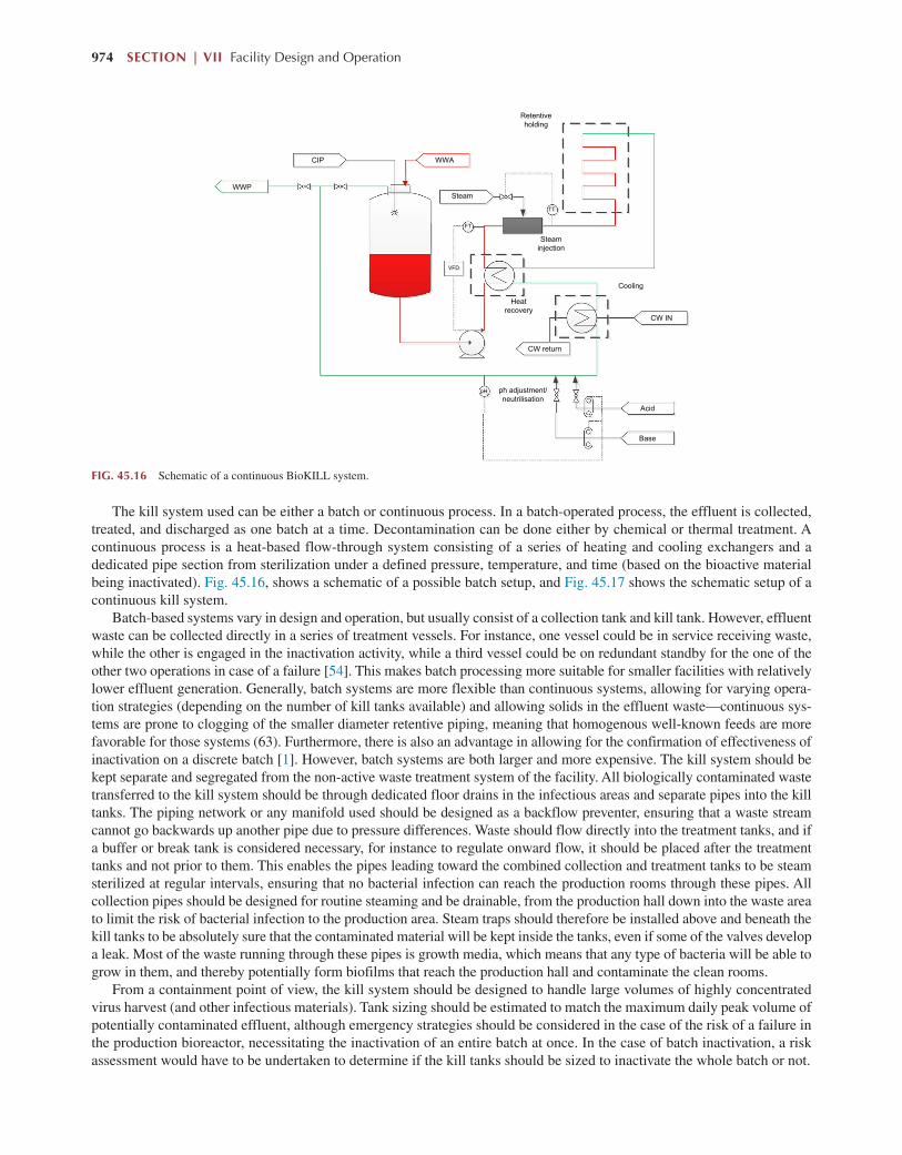
974 SECTION | VII Facility Design and Operation
The kill system used can be either a batch or continuous process. In a batch-operated process, the effluent is collected, treated, and discharged as one batch at a time. Decontamination can be done either by chemical or thermal treatment. A continuous process is a heat-based flow-through system consisting of a series of heating and cooling exchangers and a dedicated pipe section from sterilization under a defined pressure, temperature, and time (based on the bioactive material being inactivated). Fig. 45.16, shows a schematic of a possible batch setup, and Fig. 45.17 shows the schematic setup of a continuous kill system.
Batch-based systems vary in design and operation, but usually consist of a collection tank and kill tank. However, effluent waste can be collected directly in a series of treatment vessels. For instance, one vessel could be in service receiving waste, while the other is engaged in the inactivation activity, while a third vessel could be on redundant standby for the one of the other two operations in case of a failure [54]. This makes batch processing more suitable for smaller facilities with relatively lower effluent generation. Generally, batch systems are more flexible than continuous systems, allowing for varying opera-tion strategies (depending on the number of kill tanks available) and allowing solids in the effluent waste—continuous sys-tems are prone to clogging of the smaller diameter retentive piping, meaning that homogenous well-known feeds are more favorable for those systems (63). Furthermore, there is also an advantage in allowing for the confirmation of effectiveness of inactivation on a discrete batch [1]. However, batch systems are both larger and more expensive. The kill system should be kept separate and segregated from the non-active waste treatment system of the facility. All biologically contaminated waste transferred to the kill system should be through dedicated floor drains in the infectious areas and separate pipes into the kill tanks. The piping network or any manifold used should be designed as a backflow preventer, ensuring that a waste stream cannot go backwards up another pipe due to pressure differences. Waste should flow directly into the treatment tanks, and if a buffer or break tank is considered necessary, for instance to regulate onward flow, it should be placed after the treatment tanks and not prior to them. This enables the pipes leading toward the combined collection and treatment tanks to be steam sterilized at regular intervals, ensuring that no bacterial infection can reach the production rooms through these pipes. All collection pipes should be designed for routine steaming and be drainable, from the production hall down into the waste area to limit the risk of bacterial infection to the production area. Steam traps should therefore be installed above and beneath the kill tanks to be absolutely sure that the contaminated material will be kept inside the tanks, even if some of the valves develop a leak. Most of the waste running through these pipes is growth media, which means that any type of bacteria will be able to grow in them, and thereby potentially form biofilms that reach the production hall and contaminate the clean rooms.
From a containment point of view, the kill system should be designed to handle large volumes of highly concentrated virus harvest (and other infectious materials). Tank sizing should be estimated to match the maximum daily peak volume of potentially contaminated effluent, although emergency strategies should be considered in the case of the risk of a failure in the production bioreactor, necessitating the inactivation of an entire batch at once. In the case of batch inactivation, a risk assessment would have to be undertaken to determine if the kill tanks should be sized to inactivate the whole batch or not.
WWA
WWP
CIP
CW IN
CW return
Steam
Steaminjection
Retentiveholding
Heatrecovery
Acid
Base
Cooling
pHHHHHHHpH
TTTTTTTTTT
FT
VFDVFD
ph adjustment/neutrilisation
FIG. 45.16 Schematic of a continuous BioKILL system.

Facility Design and Process Utilities Chapter | 45 975
Floor drains in any infectious areas cannot be openly connected to the standard process or sanitary sewer service, but should be piped to the biological waste treatment system. Due to the low risk of contamination, BSL-1 and BSL-2 waste treatment equipment can be placed within a general utility area with the ability to use liquid disinfectants in case of a leak situation or in the event decontamination equipment needs servicing.
Solid WasteAn autoclave for the decontamination of solid waste materials such a single-use bag, filters, tubing, or small portable equip-ment is also required. This should not be the same autoclave used for sterilizing raw materials or equipment for process use (e.g., cell culture media sterilization). Decontamination autoclaves are to be dedicated to decontamination only. The autoclave should be conveniently located to minimize the distance from processing to the point of decontamination.
Depending on the biosafety level, placement of the decontamination autoclaves is important. At higher biosafety levels, waste must be deactivated prior to exiting the infectious or contained area. Therefore, autoclaves are required at the exits of the biosafety-contained work areas, as can be noted in Fig. 45.9.
45.7.7 Planning of Utility Systems
The importance of the design and installation of systems for supplying utilities that do not come into contact with products (e.g., heating steam, control air, coolants) is often underestimated. The reason for this is that these systems do not have
CIP
Steam
CIPCIP
TTTTTTTTTT TTTTTTTTTTT
Condensate Condensate
CW return
CW in
CW return
CW in
WWP
LTTTTTTTLT
TTTTTTTTTTT
LTTTTLT
TTTTTTTTTTT
WWA
Collectiontank
Bio-killtank 1
Bio-killtank 2
CW inCW return
Acid
Base
pHHHHHHHpH pH adjustment/neutrilisation
Cooling
FIG. 45.17 Schematic of a batch BioKILL system.

976 SECTION | VII Facility Design and Operation
to be qualified in accordance with good manufacturing practice guidelines, but must only be planned and constructed in accordance with good engineering practice. However, the planning and implementation of technical utility systems has a huge influence on the later operation of the production facilities. For example, process- and clean-media systems can be operated only with a partial load or not at all, if the technical utilities are not available in the required quantity and quality.
An important part of facility planning is the coordination of the interfaces between the utility generators, the distribu-tion systems, and the point-of-use equipment consumers. All interfaces that may occur must be determined and carefully coordinated.
Interfaces exist:
● Between the technical utility generators and their associated distribution systems.● Between technical utility systems and utility consumers such as process systems, clean utility systems, logistics HVAC,
and refrigeration systems.● Logistics and control systems likewise depend on a reliable supply of black utility. These consist primarily of control air,
but technical gases such as nitrogen and carbon dioxide may also be required, for air quality control in storage areas.
Generally, technical utility generator systems are housed within a central utility building externally, but close to the bio-pharmaceutical production building. The proximity is to reduce the length of expensive piping that is required to distribute generated utility to production; however, it is usually kept external for segregation purposes to reduce the risk of breakdown and then subsequent contamination of the clean space and hence possible product contamination. Moreover, there is no special need for utility systems to be housed within a controlled environment and hence does not need any clean or con-trolled space. Furthermore, the distribution piping needed for technical utilities is relatively less expensive than that needed for clean utilities. Thus, it also makes economic sense to house this equipment in a separate building. The location of the technical utility systems may also depend on where municipal media (e.g., potable water, electricity, gas) lines are situated. Close connection to the source utility is usually recommended. Fig. 45.18 shows a schematic of a possible distribution setup for utilities on a biopharmaceutical site.
U U U U UU U U U U
PWstorage
tank
WDIstorage
tankCompressor
Ca buffertank
N2
O2
CO2Production building
Central utilitybuilding
WFI generationCS generation
U U U U
Clean utilites area
Hot waterbuffertank+heater
Water filtration+ softening +dechlorination
Coldwaterbuffertank+cooler
Potable water
Waste
Boiler/steamgenerator
Oil/gas
Coolingtower
Chiller
Electricity
Heating-supplysystem:
heating waterlooptechnical steam
distribution
Facilitydistribution
Refridgeration loop& distribution
FIG. 45.18 Interfaces between main utility loops and distributions in a production facility.

Facility Design and Process Utilities Chapter | 45 977
The location of clean utility systems is dictated by the location of their point of use together with the make-up of the overall manufacturing site. Clean utility storage and distribution equipment within the facility is dictated upon a com-promise of being sufficiently far away from the clean room areas to allow easy access for engineering and maintenance personnel while also minimizing the distance of costly distribution piping to the point of use. When bringing the utilities to the point of use, care should be taken to ensure that the clean room is not compromised. A clean construction protocol should be implemented and wall, ceiling and floor penetrations, if needed, should be flashed and sealed in such a manner as to prevent contaminants from entering the clean room. Such entry points should also be smoothly sealed to ensure that there are no crevices to harbor organisms. Drains should be avoided in the clean room wherever possible. When this is not possible, the drains should be covered when not in use with a means specifically designed for biopharmaceutical clean room application (i.e., tight, smooth, cleanable, and corrosion resistant. In large facilities, a utility chase that enables major utility lines to be brought to the vicinity of process tools may be provided. Final hook-up between the chase and the point of use then becomes a relatively simple, minimally intrusive procedure. The utility chase concept is also beneficial in facilities that undergo frequent retrofit or upgrade.
In small, standalone facilities, clean utility generation equipment may be located together with the storage and distribu-tion equipment within the production building. However, in the cases where there could be several production buildings on one manufacturing site or several independent and parallel production trains in one building (for multiproduct manufacture), clean utility generation equipment could be housed externally within the central utility building together with the technical systems. It may be more economical in some cases to centralize the generation of clean utilities and then to have smaller storage and distribution loops dedicated to specific production lines or buildings. A risk analysis would need to be conducted to ensure no cross-contamination of the central utility system is possible should one of the subsystems be compromised.
45.7.8 Facility Control Systems
To this point, the discussion about facility design has focused on the functional and regulatory needs of the facility to ensure proper and efficient manufacturing. However, to ensure correct working order and control over the different functional ele-ments, the facility is overseen by two high-level, interdependent, but separate, control systems. These are the (1) building management system (BMS), which controls all the technical utilities and HVAC systems within the facility and (2) the environmental monitoring system (EMS), which is responsible for the monitoring and control of all the clean-utility and GMP-critical room environments.
Room environment, together with access control and interlocks, frequently plays an important part in the environmental segregation strategy of the facility. As a result, having adequate control and monitoring of these aspects together with other important components will further satisfy regulatory agencies that the facility has sufficient product protection controls.
Building Management SystemThe building management system (BMS) is an overarching control system that is responsible for the automatic regulation and control of non-GMP facility subsystems, maintaining predefined parameters (or set points) and the control of their functionality. The major aim of the BMS is to guarantee the safety of facility operation, while also monitoring and optimiz-ing the use and efficiency of its supervised subsystems to allow more efficient operation. Examples of the major subsystems controlled by the BMS are:
1. HVAC System. The duct temperature, pressure, and humidity, as well as exhaust temperature are connected to the BMS, and if their value exceeds defined limits, an alarm is generated.
2. Central Fume Collection, Laminar Flow Units, Dust Collection System, Central Vacuum System, Heat blowers. The BMS monitors the performance of these systems, allowing for early identification of units requiring maintenance. Sudden breakdown would signal via alarms and then appropriate action can be taken to protect the product.
3. Technical Steam System. Should, for instance, the pressure or temperature in the piping system fall below the defined regulatory values for clean steam, the BMS shall trigger an alarm, indicating a threat to product quality.
4. Hot Water System and Central Heating. Temperature and pump control monitoring via the BMS allows for a proper functioning of hot water distribution through the facility.
5. Chilled Water System. Control of the facility chillers could be supervised by BMS to monitor proper behavior of the sys-tem in terms of water/coolant temperature control or pump control to assure proper distribution within the distribution loop.
6. Sprinkler System (for fire safety).7. Electrical Monitoring System. The BMS may monitor the consumed electrical power and the state of main electrical
switches.

978 SECTION | VII Facility Design and Operation
The number of subsystems connected to the BMS and the level of control is related to the investment decision. However, the two main subsystems, which are usually accounted for in a BMS are (1) HVAC control and (2) electrical systems monitoring.
Environment Monitoring SystemA critical component of the overall facility automation is the environment monitoring system (EMS). The objective of the EMS is to continuously monitor critical GMP-relevant environmental parameters in production rooms. Critical parameters are defined as parameters that can influence the quality of the product. These are:
● Pressure● Temperature● Humidity● Air flow velocity under the laminar flow units● Air cleanliness in class A and B environments (particle counters)
Additionally, the EMS can monitor the following systems:
1. WFI and PW systems. Water temperature, pressure, flow, conductivity, and TOC values are monitored. If these fall outside the defined values, an alarm in the EMS system should appear.
2. Pure steam system. Generally, the pressure and temperature within the piping system is monitored. If these are not in the defined limits, the EMS should trigger an alarm.
3. Compressed air. The temperature, pressure, dew point, and humidity are monitored. If values fall below the defined set points, the EMS should trigger an alarm.
4. Nitrogen system, oxygen system, laboratory gases. The pressure drop on the final filter is monitored. If this is out of permissible range, the EMS should trigger an alarm.
Rooms being monitored by the EMS, such as a room in which any of the environmental parameters will be considered as process critical, should be equipped with a local panel with light-emitting diodes (LEDs), alarm warnings, and an acous-tic device. The ON/OFF status of the LED will indicate if the critical environmental parameters in the room are within the permissible limits. If the parameters are beyond the limits, a red warning light will turn on and an acoustic signal will appear. It will be possible to confirm the alarm either locally on the panel or remotely from the EMS computer station. In this way, the production personnel should be able to monitor (directly, from the production/work place) the environment in the room. The decision about which EMS parameters will be visualized by local panels with LEDs should be undertaken during the design of the EMS system. Generally, environmental changes do not occur instantaneously. Therefore, after a disturbance, the system should be allowed a degree of time to return to its required state. As such, each alarm should have a defined time-delay value to ensure that alarms are not triggered for non-emergency situations.
Because the EMS monitors all GMP-relevant data, it will need to be validated as a “computerized system.” Therefore, it will need to be designed and executed in accordance with the relevant regulation of the licensing authority. For the U.S. FDA, this regulation would be 21 CFR part 11 and GAMP 5.
In addition to the control systems supported by the BMS and EMS, consideration should also be given to other ancillary system control systems that are needed within the facility, some of which are not restricted to biopharmaceutical facilities alone. Such systems are outlined within Appendix A.
45.8 PLANNING FOR THE FACILITY SUPPORT SYSTEMS ON SITE
A biomanufacturing facility is not usually a self-supporting entity. Manufacturing is usually designed and planned to be executed on an overall site, on which would be placed several support buildings that would facilitate final product manufac-turing. Support buildings could range from metrology and engineering departments to laundry and recreational areas. This section outlines the major functions that should be considered in the support of biomanufacturing.
45.8.1 Warehousing
Warehousing plays a crucial supporting role in successful biomanufacturing. Raw materials (including single-use unit op-eration components) and even final drug product is stored within the warehouse, and as such, this building is both the start and end of biopharmaceutical manufacturing within a site.
According to the Code of Federal Regulations (21 CFR 211.80), raw materials and components used in pharmaceutical manufacturing must be received, stored, and handled in a manner designed to prevent damage, contamination, and any other adverse effects. Incoming materials must be treated and handled according to approved written procedures and current industry

Facility Design and Process Utilities Chapter | 45 979
standards. Batch integrity must be maintained from beginning to end, and record-keeping begins with the Certificate of Analysis delivered with each shipment. All incoming materials and components must be treated as “quarantined” until proper sampling, inspection, testing, and release can be carried out by in-house personnel. For this reason, receiving and warehouse areas must be designed with adequate space and security measures to separate quarantined materials and materials under test from those released for use. Thus, warehouse design and layout is also subject to cGMP guidelines. Each warehouse will have a quarantine area where incoming raw materials and components are stored before being released for production or packaging. This may be an area separated from other areas with walls or open fencing or by other methods such as delineation on the floor. These are just examples of the design; however, a separate area may make it easier to avoid any mix ups because of physical separation.
To facilitate raw material sampling, it is helpful to include a sampling room adjacent to the warehouse with a laminar flow curtained area and stainless steel workbenches. Quality Control personnel can then take representative test samples in a controlled environment without having to move large material containers to an appropriate testing laboratory. In addi-tion, most biotechnology production facilities include an area for storage of their master and working cell banks. These cell banks—the most valuable raw material in any facility—are stored in several liquid nitrogen dewars or ultra-low tempera-ture freezers. Daily monitoring of nitrogen levels and/or freezer temperature is required, and access is limited. Elaborate alarm systems and video surveillance of the cell bank storage area maintain a high level of security 24 hours a day. Material storage and warehousing issues become increasingly more important as the processes are scaled-up and the quantities of raw materials increase.
A well-planned biopharmaceutical facility must take into consideration all the various materials that will be maintained in inventory and the various methods of storage required. Incoming raw materials must be isolated and tested for quality control before being released for general use. Some materials have specific temperature sensitivity that requires refrigerated storage or freezers. Large quantities of flammable liquids must be isolated in separate storage areas that meet the require-ments of the building and fire codes. In addition, waste solvents must also be contained, isolated, and potentially stored for pick-up by a waste removal company. Final product storage must allow for quarantine and release areas for final quality testing and provide security for the product as well. A local quality control testing lab is required if the warehouse is remote from the general laboratories of the facility. Also, a large general storage area for the hundreds of small items required to support the process and the gowning/cleaning protocols must be included. Finally, sufficient office space must be provided for warehouse personnel and for Quality Assurance to handle the volumes of paperwork generated by the controlled track-ing of all these materials.
45.8.2 Quality Control Building & Laboratories
The responsibilities of quality control include testing incoming material, in-process-controls (IPCs), product-release ana-lytics, stability testing, and environmental monitoring. Investments in premises, equipment, and staff to manage all these tasks can become significant. Special consideration should be given to the increased sampling schedule during qualifica-tion, and cleaning and process validation, because analytical capacities can become limiting in these phases.
The design of laboratories will not be further detailed here. Obviously, demand planning is essential, providing a good projection of the amount and types of analysis needed. Apart from the special requirements for handling of biological sub-stances, quality control laboratories in biotechnological production do not differ from other quality control laboratories.
45.8.3 Central Utilities Building
A central utility building (CUB) is, in general, a mainstay of any production site. Its purpose is to receive the incoming technical utilities from the local municipality, and process these sufficiently to allow supply to the clean utility systems (as described in Section 45.7.4) as well as the other necessary technical utilities of the site (e.g., hot, cold water, heating, etc.).
45.8.4 Fill –Finish for Drug Product Production
This chapter has focused on the facility design for the manufacture of bulk drug substances. However, manufacturing of the drug will not be completed at that stage. Fill finish operations are undertaken to formulate and format the drug substance into a viable means for transferring the drug to the end user patient. It is responsible for turning the bulk drug substance (BDS) into a drug product (DP). As such, it represents as important (if not more) a step of manufacturing as the bulk drug.
It is common to have fill-finish activities de-coupled from BDS manufacturing. BDS is frequently frozen and trans-ported to an alternative location where filling can take place. Typically the location is closer to where drug distribution to the market will take place.

980 SECTION | VII Facility Design and Operation
45.8.5 Location
Some, if not all of these support functions could be outsourced to third parties to reduce the capital investment required to set up the project. This will be dependent on the location of the facility and the associated services present within that locality. There are indeed many factors to consider in terms of choosing a location for the construction of a new facility, but some are crucial.
Corporations are interested in corporate taxes, local taxes, and charges that they will pay in a particular location. They will be looking at their transfer pricing policy. They may have a treasury strategy. They may set up their financial head-quarters in a location alongside their manufacturing base. Companies will surely look at the availability of granted training support, and they will be very interested in their cost base; that is, the cost of labor, salaries, wages, transport, and shipping. Very importantly in the European context, companies will be interested in access to markets in certain countries, particu-larly European Union countries.
Looking at the infrastructure and support services side of things, manufactured product must be brought to the market. Therefore, effective distribution, including storage and freight transport by road, rail, air, and sea, are very important. Regarding a specific location, a company may prefer to set up where there is already a cluster of similar clients with similar requirements. If such a cluster exists, there is likely to be support services available, such as laboratory services, maintenance services, project management, and regulatory expertise as well as educational and research support from nearby institutes and colleges.
The third important consideration is the availability of people who will operate and manage the plant. It is crucial to have a strong pool of talented people who are well-educated, experienced, and flexible. Those people should also have continuing access to training and education.
45.9 FACILITY CONSTRUCTION
45.9.1 Execution Steps
Identifying a partner or partners to support the design and build of a facility and the process that sits within it is the first key decision. Traditionally, an architectural and engineering firm and one, or possibly multiple, single-use process- equipment supply partners are selected. Working with a single external point of contact can help drive efficiencies in project- management and delivery. To be successful, however, the lead partner will need an understanding of biomanufac-turing facility design, engineering, qualification, and validation, as well as the operational aspects of combining process hardware, single-use consumables, and automation platforms. Overall, there are four sets of requirements to consider: product(s) to be made, process technologies, facility design, and supporting services. In each case, a series of questions will help identify objectives, design specifications, and potential constraints. Aligning requirements for all these will be important in establishing the correct design going forward.
The following project steps are generally envisaged in the design, construction, and qualification of a biopharmaceutical facility:
● A conceptual study, where the main aim is to conceptualize the facility design, gain an idea of project timelines, and to estimate an investment cost to a +/- 30% level of accuracy.
● Basic engineering design: here the conceptual design is developed further to the extent where an investment cost to a +/- 10% accuracy is possible. In most cases after basic engineering, an investment decision may be undertaken, given the a sufficient level of security in the CAPEX.
● Detail design: This will involve the preparation of drawings, documents, and specifications leading to procurement of equipment and services. Development of verification (commissioning and qualification) documentation will also be carried out during this phase.
● Procurement: Trade contracts, major equipment packages, and equipment.● Construction based on a construction management execution approach.● System verification (commissioning and qualification, C&Q). Progressed on a system-by- system basis. Verification tests
will also be taking place during construction and FAT and off-site verification may be undertaken where appropriate. On-site verification will typically include installation and operational qualification (IQ/OQ), followed by engineering batch runs.
● PQ following final verification (C&Q) may take place on a phased basis following completion of verification. PQ is not part of the project.
Designers use a manufacturer’s project definition to collaborate with stakeholders during the front-end conceptual design (CD) and basic design (BD) phases. The importance of rigor in that phase cannot be overemphasized. Capital ex-pended is relatively small during early stages, but the ability to affect a project’s alignment with strategic needs and finan-cial maneuvers is significant. Once a flexibility consensus is reached during the CD phase, the design basis is established,

Facility Design and Process Utilities Chapter | 45 981
and triggers cross-disciplinary engineering activities. Changing the project definition at later stages is a costly approach, yet many companies hasten through the CD phase in particular under the pressure of project timelines (without evaluating options) and then are stymied at the total investment cap that can bring a project to a halt.
The conceptual design phase can introduce a project risk-management strategy that highlights the most critical issues and the design choices to be made. Every business case is founded on a set of needs and opportunities that uniquely define a manufacturer’s situation in the market. Making the wrong choices can lead to cost overruns and missed market opportuni-ties, which consequently puts the viability of a business in question. Management boards are demanding rigorous front-end planning more than ever before, and the right design questions that must be addressed are often contextual to a business plan.
45.9.2 Construction
There are two distinct routes that are commonly being taken today, a building designed and built from scratch from brick and mortar (stick-built), and a modular approach.
“Stick-built” refers to a building or structure that is of a unique design and built on-site, usually from the ground up. Architects, engineers, and contractors in general have extensive experience with this traditional approach. The familiarity of all involved from construction workers, to building inspectors, to regulatory bodies can be a significant advantage; however, although design and construction of such facilities considers the manufacturing processes that will take place inside the building, most are unique for each installation and do not account for flexibility in the future.
With a stick-built approach, the full cost of the facility is not initially clear and the design and construction phases risk overrunning. The length of the design phase for a project can be difficult to predict because the duration required for multiple design iterations and approvals can significantly extend this part of the process. Construction of a stick-built biomanufacturing facility is a linear step-wise process, and on average, the time from design to final commissioning of the completed facility, fully fitted out with equipment, can be from 30 to 36 months or even longer.
Increasingly, the concept of modularization is being considered during the construction and execution phases of a facil-ity. This can be process modularization, which the advent of single-use technologies has encouraged, or facility building modularization. In general, modular facilities are fabricated in a satellite location away from the final construction site. The modular facility starts with a pre-engineered design allowing similar facilities to be built as required. The pre-fabricated modules are transported to the final construction site and erected. The module is then fitted out and the full facility commis-sioned like a traditional stick-built approach.
Modular construction has existed for over a century and its use has fluctuated based on extreme needs during times of cri-sis or of rapid economic expansion. Technological improvements over the past two decades have greatly improved the quality and sophistication of modular building, delivering economies of scale and quality improvements that make modular con-struction competitive to stick-built construction with regard to cost, quality, and time. Construction of a modular facility is a non-linear and parallel process. While the site and foundation work is being performed, the building modules are constructed off-site in a factory setting. With a pre-designed modular option, the critical engineering design phase is very short, as only minor design changes may be required. The concept here is to anticipate and pre-engineer the facility to some degree prior to the start of any project. Because these construction phases are performed in parallel, the time savings can be significant.
This non-linear process lends itself well to platform biomanufacturing where much of the concepts and thinking are already industry standard. Fully understanding the needs and constraints of the manufacturing processes allows the design-ers to create a facility that is ergonomic, efficient, flexible and fit for a specific purpose. When this insight is coupled with a deep understanding of robust modular building construction, it is possible to deliver state-of-the-art biomanufacturing facilities in very short timeframes within a fixed cost, agreed to in advance.
Once a facility is designed, construction can be repeated for as many facilities as needed. If another facility is required in another location, then the company has acquired a design that can be readily reproduced. Although each site is different, there should only be minimal changes based on site conditions, such as mitigating earthquake risk or climate variation, and therefore no extra time required for additional feasibility studies. Alternatively, if needed, the entire modular facility could be disassembled and shipped elsewhere. The ‘design once and build repeatedly’ approach of modular construction means that consistent, high-quality facilities can be readily deployed in any market to meet local biomanufacturing needs, a con-cept commercialized by GE Healthcare’s KUBioTM concept based on single-use production lines.
There is now a clear trend toward increasing the quality of the buildings themselves. Quality is a key driver with high building standards being of equal importance to process equipment. There are numerous regulations with respect to clean room walls, ceilings, and finishes, and the highest standards can be difficult to achieve without experience. With the finish quality of a building viewed as important as the product, ensuring a high degree of control over quality is required to ensure compliance with EMEA, FDA, and CFDA regulatory standards.

982 SECTION | VII Facility Design and Operation
45.10 SUMMARY: CONSIDERATIONS WHEN PLANNING A NEW FACILITY
Biomanufacturing facilities can be divided into process, facility, and infrastructure components. Each plays a significant role in the success of a manufacturing enterprise. A failure or weakness in either will lead to poor product quality and/or inefficient manufacturing. Improvements in manufacturing technologies and advancements in single-use systems have clearly transformed bioprocesses. Together with those process improvements comes modular construction, which will become more and more common because modular alternatives can have smaller footprints than traditional facilities and be deployed rapidly in locations where clean-room and piping expertise may not be readily available.
Smaller, greener, and more flexible facilities of the future that look to new technology solutions may also enable a key industry transition from fixed to variable cost structures to structures that follow demand. Defining and understanding the business drivers, uncertainties, and risks associated with building and operating bio-manufacturing facilities is a key first step in the development of future generation manufacturing facilities.
Success of future facility design must be measured in terms of flexibility and efficiency while providing a platform that supports and facilitates the operational excellence required to reliably produce high-quality product, while meeting an ever-evolving set of regulatory compliance requirements. As the industry looks to make the transition from current state to the future model, new enabling technologies can provide manufacturing platforms that meet the goals of being flexible with low capital unit operations changeovers, efficient movement to new markets, and a scale-out approach with smaller increments of capacity from highly productive processes to meet lower demand markets.
Operational excellence is the fundamental driver for producing high-quality product and efficiently meeting all neces-sary regulatory requirements. A flexible layout is important, especially for sites working with combinations of products, product classes, and host-cell types. Regardless of the approach undertaken, the important issue is how the designer can combine single-use and stainless steel technologies to provide the most productive, cost-effective and regulatory risk-optimized process in a faster and more predictable way.
APPENDIX A
A.1 Clean Room Classifications
The European Union standard as listed in the EU GMP Annex 1 is shown in Table A.1. EU guidelines require clean rooms to meet particle counts in two different room states:
(1) At rest—the state of cleanrooms is the condition where the production equipment is installed and operational but not in operation.
(2) In operation—the state of the clean rooms is the condition where the installation is functioning in the defined operating mode with the specified number of personnel working.
For sterile manufacturing, there are also limits imposed on microbiological activity, which are stated within the “in operation” state Table 45.1. The FDA guidance is set out in Table A.2 and requires adherence while the room is “in operation.”
A.2 Ancillary Control Systems
Ancillary control systems is given in Table A.3.
TABLE A.1 EU GMP Clean Room Classification Definitions
Clean Area Classification (0.5 μm Particles/ft3)
ISO Designation
≥0.5 μm Particles
Microbiological Active Air Action Levels (cfu/m3)
Microbiological Settling Plates Action Levels (diam. 90 mm; cfu/4 h)
100 5 3520 1 1
1000 6 35,200 7 3
10,000 7 352,000 10 5
100,000 8 3,520,000 100 50

Facility Design and Process Utilities Chapter | 45 983
TABLE A.2 US FDA Clean Room Classification Definitions
Maximum Permitted Number of Particles per m3 Equal to or Greater Than the Tabulated Size
“At Rest” “In Operation”
Grade 0.5 μm 5 μm 0.5 μm 5 μm
A 3520 20 3520 20
B 3520 29 352,000 2900
C 35 2900 3,520,000 29,000
D 3,520,000 29,000 Not defined Not defined
TABLE A.3 Ancillary Systems Controlled by a Building Management System
Purpose Main Components Comments
Access Control System
• Controls the access of all employees within the different zones in the plant
• Work time registration (optional)
• Cooperation with the fire alarm system (unlocking all doors in case of fire)
• Central computer and system server with user data base
• Door blocking devices (electric strike, electromagnetic lock)
• Proximity cards and card readers
• Backup batteries• Emergency exit push-buttons
• Access Control System should be connected to a fire alarm system to ensure that the doors automatically unlock during an emergency.
• Access Control System should be equipped with backup supply (batteries), which guarantees possibility of operation in case primary supply is lost.
Fire alarm system (FAS)
• Heat and/or smoke detection
• Alarming and specific scenario execution in case of fire alarm
• Protection of rooms and areas over the suspended ceilings
• Automatic smoke and heat detection
• Fire alarm control panel• Manual call points• Optical and acoustic
signalization• Backup batteries
• Fire alarm systems will need to comply with local fire regulations. As such, sprinkler systems or other may need to be connected to the FAS.
• Similar the FAS may need to be connected to several other systems within the facility to ensure safe precaution in the event of an emergency eg Turning off the HVAC system; Unlocking doors protected by the Access Control System, Airlock System; Turning off the Central Fume Collection System; Opening the roof-mounted smoke hatches by turning on their control units.; Closing fire dampers; Sending an order to elevators automation system—lifts go to the ground floor.
• The Fire Alarm control panel should be equipped with backup power supply (batteries), which guarantees the possibility of operation in case of primary supply is lost.
Airlocks control system
• Avoids having more than one door opened at the same time between cleanliness zones
• Blocking airlock doors
• PLC controllers (autonomous for each airlock)
• Door reed switches monitoring the position of the door
• Door blocking devices (electric strike, electromagnetic lock)
• Optical signalization (green and red light)
• Emergency exit push-button• Buzzer (optional)• Backup batteries
• Emergency exit buttons should be located on both sides of each protected door.
• Each door should be equipped with indication lamps (green—access allowed, red—access forbidden). In the normal state, doors are locked and closed—green lamps are on.
• Opening any airlock doors will block all other connected doors and switch on the red lamps.
• All door locks should be fail-safe, which means they will unlock when power supply is lost.
• Each airlock signalization and control system will be independent and will not be integrated with any automation system in the building.
• The lock power supply will be connected to the FAS to ensure automatic door unlocking when a fire alarm occurs.
Continued

984 SECTION | VII Facility Design and Operation
REFERENCES [1] S. Miller, D. Bergmann, Biocontainment design considerations for biopharmaceutical facilities, J. Ind. Microbiol. 11 (1993) 223–234. [2] Report from Deloitte Consulting “Advanced Biopharmaceutical Manufacturing: An Evolution Underway”, 2015, https://www2.deloitte.com/
content/dam/Deloitte/us/Documents/life-sciences-health-care/us-lshc-advanced-biopharmaceutical-manufacturing-white-paper-051515.pdf. [3] H. Levine, R. Stock, J. Lilja, A. Gaasvik, H. Hummel, T. Ransohoff, S. Jones, Single-use technology and modular construction, Bioprocess Int. 11
(S4) (2013) 40–45. [4] ISPE Baseline Pharmaceutical Engineering Guide for New and Renovated Facilities Volume 6, Biopharmaceutical manufacturing facilities, first
edition, Section 3, 2004. [5] D.C. Snow, S.C. Wheelwright, A.B. Wagonfeld, Genentech—Capacity Planning, Harvard Business School Case 606-052, Boston, 2005. [6] P. Kaminsky, M. Yuen, Production capacity investment with data updates, Oper. Eng. Anal. 46 (7) (2014). [7] Aeby Thomas and Morten Munk, Meeting the demand for a new generation of flexible and agile manufacturing facilities: an engineering challenge,
Bioprocess International, Supplement, Facility Design/Engineering, Single Use, December 2015. [8] K.J. Morrow, Disposable bioreactors gaining favour: new components and systems improve process reliability and reduce cost, Nav. Res. Logist.
(NRL) 26 (12) (2006) 42–45. [9] J. Blackwell, T. Ransohoff, H. Levine, Monoclonal antibody manufacturing strategies for the 21st century, Pharma. Outsourcing 11 (4) (2010) 28–35. [10] E. George, S. Farid, Strategic biopharmaceutical portfolio development: an analysis of constraint-induced implications, Biotechnol. Prog. 24 (2008)
698–713. [11] W. Brastow Jr., C. Rice, Planning pharmaceutical manufacturing strategies in an uncertain world, Bioprocess Int. 1 (6) (2003) 46–55. [12] M. Cha, B. Rifai, P. Sarraf, Pharmaceutical forecasting: throwing darts? Nat. Rev. Drug Disc. 12 (2013) 737–738. [13] J.A. DiMasi, H.G. Grabowski, R.W. Hansen, Innovation in the pharmaceutical industry: New estimates of R&D costs, J. Health Econ. 47 (2016) 20–33. [14] R. Hernandez, Managing biomanufacturing capacity expectations, BioPharm Int. 29 (7) (2016) 2–6. [15] J.A. DiMasi, R.W. Hansen, H. Grabowski, The price of innovation: new estimates of drug development costs, J. Health Econ. 22 (2003) 151–185. [16] E.L. Plambeck, T.A. Taylor, Sell the plant? the impact of contract manufacturing on innovation, capacity, and portability, Manag. Sci. 51 (1) (2005) 133–150. [17] J.A. Van Mieghem, Coordinating investment, production, and subcontracting, Manag. Sci. 45 (7) (1999) 954–971. [18] X. Chao, H. Chen, S. Zheng, Dynamic capacity expansion for a service _rm with capacity deterioration and supply uncertainty, Oper. Res. 57 (1)
(2009) 82–93. [19] J. Chod, N. Rudi, Strategic investments, trading, and pricing under forecast updating, Manag. Sci. 52 (12) (2006) 954–971. [20] R. Hernandez, Managing biomanufacturing capacity expectations, BioPharm Int. 29 (7) (2016) 2–6.
TABLE A.3 Ancillary Systems Controlled by a Building Management System—cont’d
Purpose Main Components Comments
Anti-burglary system & CCTV
• Alarming and execution of predefined functions in case of burglary
• Indication of rooms in which the alarm went off
• Activated during night time and all other non-production time
• Video observation of predefined areas (indoors and outdoors)
• Archiving of video recordings (for a specified period)
• Extension for the Anti-burglary system
• Motion detectors (in each monitored room)
• Main controller• Backup batteries• Color video cameras• Monitors• Computer with dedicated
software• Data servers
• The purpose of these systems is to protect the facility against unauthorized access
Computer/Telephone Network
• Providing network distribution for telephone and IT
• IT-server mainframe• Local distribution frames• Automation server frames• IT/Phone sockets
–
Public Address System
• Making announcements via loudspeakers
• Loudspeakers• Mixer—amplifier• Microphones
• The system should be designed to allow making announcements to particular zones or to all zones simultaneously.

Facility Design and Process Utilities Chapter | 45 985
[21] E.R. Gold, D. Castle, L.M. Cloutier, A.S. Daar, P.J. Smith, Needed: models of biotechnology intellectual property, Trends Biotechnol. 20 (8) (2002) 327–329.
[22] A. Signore, T. Jacobs, Good Design Practises for GMP Pharmaceutical Facilities, Taylor and Francis Group LLC, Boca Raton, FL, 2005. [23] K. Nelson, Cell Culture Technology for Pharmaceutical and Cell-Based Therapies, Chapter 16, Facility Design, in: Sadettin S. Ozturk, Wei-Shou Hu
(Eds.), CRC Press, Taylor and Francis Group, Boca Raton, FL, 2005. [24] J.N. Odum, Biopharmaceutical facility design and validation, Encycl. Ind. Biotechnol. (2013) 655–675. [25] P. Gil, J. Rogalewicz, S. Chalk, S. Probst, T. Palberg, M. Kennedy, J. Johnson, K. Green, Challenging the cleanroom paradigm for biopharmaceutical
manufacturing of bulk drug substances, Biopharm. Int. 24 (8) (2011). [26] K. Martin Remington, Fundamental Strategies for Viral Clearance—Part 1: Exploring the Regulatory Implications, BioProcess International online
post; posted January 13, 2015 3:20 pm. [27] ISPE Good Practice Guide: Heating, Ventilation, and Air Conditioning (HVAC), September 2009. [28] Forty-fifth report of the WHO Expert Committee on specifications for pharmaceutical preparations, WHO Technical Report Series, 961; Annex 5
Supplementary guidelines on good manufacturing practices for heating, ventilation and air-conditioning systems for non-sterile pharmaceutical dos-age forms (http://www.who.int/medicines/areas/quality_safety/quality_assurance/SupplementaryGMPHeatingVentilationAirconditioningSystems NonSterilePharmaceuticalDosageFormsTRS961Annex5.pdf, accessed 20th March 2017).
[29] M. Von Stwolinksi, ISPE Biopharmaceutical Baseline Guide Chapter 6—Facilities. Presented Omaha, USA, April 14, 2005. [30] ISPE Baseline Guide: Sterile Product Manufacturing Facilities, second ed., 2011. [31] Baseline Guide Volume 1, Active Pharmaceutical Ingredients Revision to Bulk Pharmaceutical Chemicals, second ed., 2007. [32] Baseline Guide Volume 2, Oral Solid Dosage Forms, second ed., 2009. [33] Guidelines for Process Safety in Bioprocess Manufacturing Facilities, Appendix B—Large Scale Biosafety Guidelines, 2011 American Institute of
Chemical Engineers, Inc., pp. 161–176. [34] Council Directive 90/679/EEC of 26 November 1990 on the protection of workers from risks related to exposure to biological agents at work, OJ
No. L 374, p. 1. [35] Centres for Disease Control and Prevention: Biosafety in Microbiological and Biomedical Laboratories (BMBL) 5th Edition, Section IV—
Laboratory Biosafety Level Criteria, 2009. [36] V. Halkjaer-Knudsen, Designing a facility with both good manufacturing practise (gmp) and biosafety in mind: synergies and conflicts, Appl. Biosaf.
12 (1) (2007) 7–16. [37] Lars Hagel, Günter Jagschies, G.K. Sofer, Handbook of Process Chromatography: Development, Manufacturing, Validation and Economics,
Academic, London, 2008. [38] A. Thomas, M. Munk, Meeting the demand for a new generation of flexible and agile manufacturing facilities: an engineering challenge, Bioprocess
Int. 13 (11) (2015) 16–23. [39] D. Wolton, A. Rayner, Lessons learned in the ballroom, Pharma. Eng. 34 (4) (2014). Accessed from: http://www.ispe.org/pharmaceutical_engineering/
july2014. [40] S. Probst, S. Chalk, M. Zicaro, P. McDuff, L. Pranzo, L. Dooley, R. Moser, F. Urbanski, P. Smock, K. Green, New challenges to the cleanroom paradigm
for multi-product facilities, Biopharm. Int. 26 (5) (2013). Accessed from:http://www.biopharminternational.com/biopharm-international-05-01-2013. [41] S. Behme, Manufacturing of pharmaceutical proteins, from technology to economy, Wiley-Blackwell, Weinheim, 2009. Chapter 8. [42] ASME BPE 2016, Bioprocessing Equipment, ASME International, 10/14/2016. [43] W. Whitford, Single-Use Systems as Principal Components in Bioproduction, Bioprocess Int. 8 (11) (2010) 34–44. [44] S. Rush, Chapter 5: Cleaning cycle sequences, in: Dale A. Seiberling (Ed.), Clean-in-Place for Biopharmaceutical Processes, CRC Press, Boca
Raton, FL, 2007, pp. 73–79. [45] J. Anker, Chapter 3: Water for the CIP system, in: Dale A. Seiberling (Ed.), Clean-In-Place for Biopharmaceutical Processes, CRC Press, Boca
Raton, FL, 2007, pp. 73–79. [46] ASME Standard for Bioprocess Equipment (BPE), 2014. [47] Supplementary Guidelines on Good Manufacturing Practices for Heating, Ventilation and Air-Conditioning (HVAC) Systems for Non-Sterile
Dosage Forms, World Health Organisation, Revision 2, 2005. [48] Annex 5: Supplementary guidelines on good manufacturing practices for heating, ventilation and air conditioning systems for non-sterile pharma-
ceutical dosage forms, WHO Technical Report Series, No. 961, 2011. [49] European Medicines Agency, GDP/GMP Inspectors working group, Questions and answers on production of water for injections by non-distillation
methods—reverse osmosis and biofilms and control strategies, 10 June 2016: http://www.ema.europa.eu/docs/en_GB/document_library/Scientific_guideline/2016/08/WC500211657.pdf.
[50] ISPE Good Practice Guide: Process Gases, July 2011. Van Vaerenbergh, B; Willemarck, N; Brosius, B; Leunda, A; Baldo, A; Do Thi; Effluent decontamination systems, Biosafety and Biotechnology Unit, December 2012, Institute of Public Health Belgium. http://www.biosafety.be/CU/PDF/2012_EffluentDeconSystems_SBB_2505_58.pdf.
[51] M.J. Ebling, S. Miller, Validation of a batch type biological waste treatment system, Pharm. Eng. 11 (1991) 42–48. [52] C.J. Carlson, Biowaste systems, Pharm. Eng. 21 (2001) 70–82. [53] D. Gordon, J. Krishnan, L. Wittmeier, S. Theriault, Investigation of the benefits of using direct steam injection in effluent treatment systems, Appl.
Biosaf. 14 (4) (2009) 165–173. [54] G. Tremblay, R.C. Langer-Curry, C. Kiley, C. Ziegler, Effluent decontamination systems: addressing the challenges of planning, designing, testing
and validation, Appl. Biosaf. 15 (3) (2010) 119–129.

986 SECTION | VII Facility Design and Operation
FURTHER READING [1] E. Jain, A. Kumar, Upstream processes in antibody production: Evaluation of critical parameters, Biotechnol. Adv. 26 (2008) 46–72. [2] A.A. Shukla, J. Thömmes, Recent advances in large-scale production of monoclonal antibodies and related proteins, Trends Biotechnol. 28 (2010)
253–261. [3] F. Li, N. Vijayasankaran, A. Shen, R. Kiss, A. Amanullah, Cell culture processes for monoclonal antibody production, Pharm. Sci. Encycl. 2 (2010)
466–479. [4] B. Kelley, Very large scale monoclonal antibody purification: The case for conventional unit operations, Biotechnol. Progr. 23 (2007) 995–1008. [5] J.H. Chon, G. Zarbis-Papastoitsis, Advances in the production and downstream processing of antibodies, New Biotechnol. 28 (2011) 458–463. [6] B. Kelley, Industrialization of mAb production technology: the bioprocessing industry at a crossroads, MAbs 1 (2009) 443–452. [7] Standard ISO-14644-4, Clean Rooms and Associated Controlled Environments—Part 4: Design, Construction, and Start Up.

本文献由“学霸图书馆-文献云下载”收集自网络,仅供学习交流使用。
学霸图书馆(www.xuebalib.com)是一个“整合众多图书馆数据库资源,
提供一站式文献检索和下载服务”的24 小时在线不限IP
图书馆。
图书馆致力于便利、促进学习与科研,提供最强文献下载服务。
图书馆导航:
图书馆首页 文献云下载 图书馆入口 外文数据库大全 疑难文献辅助工具