Facile Fabrication of Porous Conductive Thermoplastic ... Li et al. printed macroporous CNT/TPU...
19
Facile Fabrication of Porous Conductive Thermoplastic Polyurethane Nanocomposite Films via Solution Casting Wu, T., & Chen, B. (2017). Facile Fabrication of Porous Conductive Thermoplastic Polyurethane Nanocomposite Films via Solution Casting. Scientific Reports, 7, [17470]. DOI: 10.1038/s41598-017-17647-w Published in: Scientific Reports Document Version: Peer reviewed version Queen's University Belfast - Research Portal: Link to publication record in Queen's University Belfast Research Portal Publisher rights © 2017 The Authors. This is an open access article published under a Creative Commons Attribution License (https://creativecommons.org/licenses/by/4.0/), which permits unrestricted use, distribution and reproduction in any medium, provided the author and source are cited. General rights Copyright for the publications made accessible via the Queen's University Belfast Research Portal is retained by the author(s) and / or other copyright owners and it is a condition of accessing these publications that users recognise and abide by the legal requirements associated with these rights. Take down policy The Research Portal is Queen's institutional repository that provides access to Queen's research output. Every effort has been made to ensure that content in the Research Portal does not infringe any person's rights, or applicable UK laws. If you discover content in the Research Portal that you believe breaches copyright or violates any law, please contact [email protected]. Download date:21. May. 2018
Transcript of Facile Fabrication of Porous Conductive Thermoplastic ... Li et al. printed macroporous CNT/TPU...
Facile Fabrication of Porous Conductive Thermoplastic PolyurethaneNanocomposite Films via Solution Casting
Wu, T., & Chen, B. (2017). Facile Fabrication of Porous Conductive Thermoplastic Polyurethane NanocompositeFilms via Solution Casting. Scientific Reports, 7, [17470]. DOI: 10.1038/s41598-017-17647-w
Published in:Scientific Reports
Document Version:Peer reviewed version
Queen's University Belfast - Research Portal:Link to publication record in Queen's University Belfast Research Portal
Publisher rights© 2017 The Authors.This is an open access article published under a Creative Commons Attribution License (https://creativecommons.org/licenses/by/4.0/),which permits unrestricted use, distribution and reproduction in any medium, provided the author and source are cited.
General rightsCopyright for the publications made accessible via the Queen's University Belfast Research Portal is retained by the author(s) and / or othercopyright owners and it is a condition of accessing these publications that users recognise and abide by the legal requirements associatedwith these rights.
Take down policyThe Research Portal is Queen's institutional repository that provides access to Queen's research output. Every effort has been made toensure that content in the Research Portal does not infringe any person's rights, or applicable UK laws. If you discover content in theResearch Portal that you believe breaches copyright or violates any law, please contact [email protected].
Download date:21. May. 2018
1
Facile Fabrication of Porous Conductive Thermoplastic
Polyurethane Nanocomposite Films via Solution Casting
Tongfei Wu1 and Biqiong Chen1,2*
1Department of Materials Science and Engineering, University of Sheffield, Mappin Street,
Sheffield S1 3JD, United Kingdom
2School of Mechanical and Aerospace Engineering, Queen’s University Belfast, Stranmillis
Road, Belfast BT9 5AH, United Kingdom
ABSTRACT
Porous conductive polymers are one of important materials, featuring lightweight, large specific surface
area and high porosity. Non-solvent induced phase separation is widely employed to prepare porous
polymer sheet materials. Through utilizing water vapor in ambient environment as the non-solvent, a facile
approach was developed to produce porous conductive polymer nanocomposites using the conventional
solution-casting method. Without using any non-solvent liquids, porous carbon nanofiber/thermoplastic
polyurethane (CNF/TPU) nanocomposites were prepared directly by solution casting of their
dimethylformamide (DMF) solutions under ambient conditions. The strength of the CNF framework
played a key role in preventing the collapse of pores during DMF evaporation. The dependence of porous
structures on CNF loading was studied by scanning electron microscopy and porosity measurement. The
influence of CNF loading on the mechanical properties, electrical conductivity and piezoresistive behavior
was explored.
2
Introduction
Thermoplastic polyurethane (TPU) is a kind of multi-block copolymers, typically synthesized from a di-
isocyanate and a long-chain diol with a small molecule diol as the chain extender1. Through end-use-
oriented choice of the di-isocyanates and diols, a huge number of TPUs with various physical properties
have been developed2. TPU elastomers feature soft segments with glass transition temperature (Tg) lower
than room temperature (typically, -30 ~ 20 oC)3. The hard segment comprises rigid backbone moieties,
rich of potential hydrogen-bonding sites (i.e. urethane groups), forming the hard domain through
microphase separation, and serving as the physical cross-linkage in TPU elastomers4. Owing to their
mechanical robustness, high resilience, small compression set, and excellent resistance to impacts,
abrasions, tears, and weather, TPU elastomers have been extensively used over the fields of coatings,
footwear, automotives and biomedical industry5.
Recently, electrically conductive TPU composites have arisen comprehensive interest in electrical
areas like antistatic, electromagnetic shielding and sensing materials6. To prepare conductive TPU
composites, embedding conductive fillers (e.g. conductive carbon black, nanotubes, nanofibers, graphene,
silver nanowires, metal microparticles) within TPU elastomers is one attractive method, in terms of the
advantages of manufacture simplicity, cost-effectiveness, and tuning of conductivity7. However, it is
difficult to develop highly conductive TPU composites by increasing the loading of conductive fillers and
simultaneously conserve the outstanding resilience originating from TPU elastomers8. This drawback will
eventually worsen the stretchability and durability of the material. Porous structures (e.g. foams, sponges,
aerogels), which feature lightweight, large specific surface area and high porosity, have been explored as
a promising measure to tackle this issue. The application of porous materials have been widely spread
over biological scaffolds9, catalyst carriers10, membrane filters11, thermal insulators12, super chemical
adsorbents13, and energy absorbers14. Meanwhile, porous conductive polymer composites have
demonstrated great potential in novel electronics, including electromagnetic interference shielding15,
triboelectric generators16 and piezoresistive sensors17. The introduction of appropriate porous structures
not only helps to effectively reduce the density and cost, but also enables the materials with improved
flexibility, stretchability, and strain at break.
There are many approaches to introduce porous structures to TPU elastomers, such as in situ
polymerization/batch foaming18, extrusion foaming19, template leaching20, phase inversion21, solution
blowing22, thermally induced phase separation23, selective laser sintering24, and electrospinning25-27. Most
of these methods can be readily employed to develop porous conductive TPU composites. For instance,
3
Li et al. printed macroporous CNT/TPU composite materials from CNT-coated TPU particles using
selective laser sintering28. The resulting materials exhibited high conductivity, good flexibility and great
durability. The electrical conductivity showed a low percolation threshold of 0.2 wt.% and 0.1 S/m was
achieved at 1 wt.% CNT loading. Lately, Hou et al. reported a set of porous graphene/TPU composites
prepared by the infiltration of TPU into graphene scaffolds29. A maximum graphene loading of 10 wt.%
was achieved, and the porous graphene/TPU composites showed high compression modulus and low
thermal conductivity. Porous conductive CNT/TPU composites were also developed by using carbon
dioxide as foaming agent30. It was found the percolation threshold of porous CNT/TPU nanocomposites
was higher than their solid counterparts, attributed to the volume expanding. Freeze drying method is a
combination of thermally induced phase separation and template-leaching-like techniques. Porous
conductive CNT/TPU and graphene/TPU composites prepared by freeze drying exhibited high porosity
(up to 90%) and well-defined piezoresistive behavior17,31,32. Phase inversion, involving non-solvent
induced phase separation, is considered as a facile and low-energy-consuming approach to prepare
membranes with well-defined cell structures33. It was found that when exposed to water vapor, TPU
dissolved in dimethylformamide (DMF) and N-methyl-2-pyrrolidone (NMP) would be precipitated. If the
concentration was high enough, the TPU solution would transform into an organogel. But, the porous
structure in the TPU organogel could not be held during the evaporation of solvent because of the
evaporation-induced shrinkage, as illustrated in a following section. To avoid the collapse of the porous
structure, Chen et al. immersed the organogel into non-solvent water to solidify the framework and the
resultant porous graphene/TPU composites exhibited lower modulus, larger elongation at break, and lower
hysteresis7.
In this study, to avoid the collapse of the porous structure in TPU organogel, we utilized carbon
nanofibers (CNFs) to cement the porous structure and developed a facile approach to produce porous
conductive TPU nanocomposite films using the conventional solution-casting method. Without using any
non-solvent liquids, porous CNF/TPU nanocomposites were prepared directly by solution casting of their
DMF solutions in the ambient environment. The porous structures and their dependence on CNF loadings
were studied by using scanning electron microscopy (SEM) and porosity measurement. The influences of
CNF loading on the mechanical properties, electrical conductivity and piezoresistive behavior of the
porous nanocomposites were investigated. To the best of our knowledge, few studies have declared the
preparation of microcellular polymer nanocomposites directly by solution casting. This study provides a
novel and facile approach to produce lightweight conductive polymer films.
4
Results and discussion
Preparation of porous CNF/TPU nanocomposites
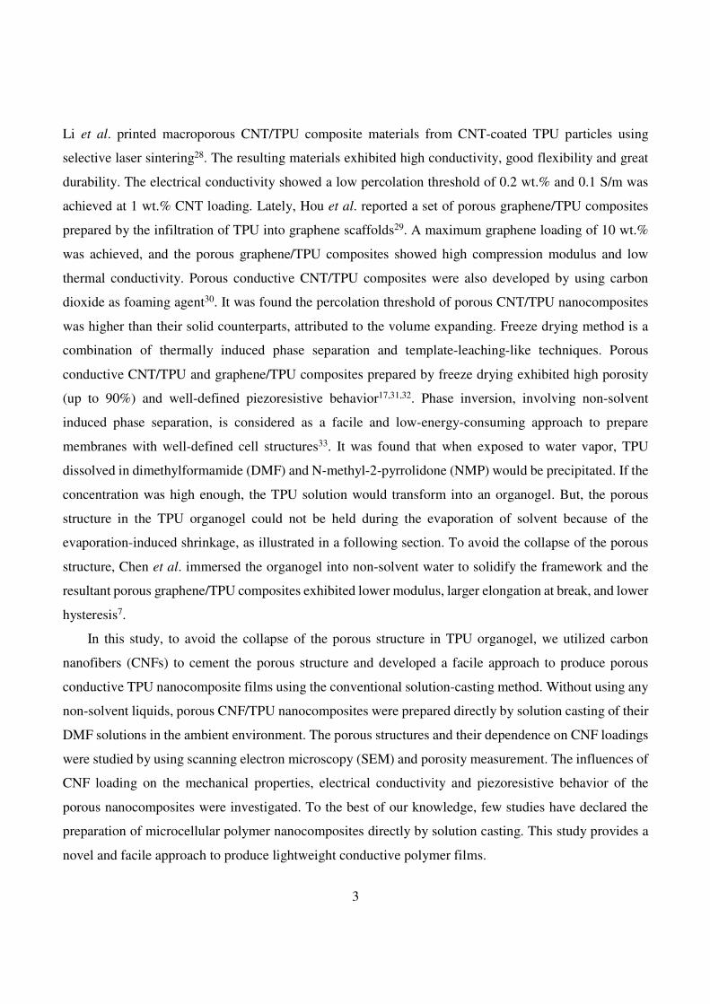
Figure 1. Digital photographs of a TPU DMF solution (0.08 g/mL) (a), TPU DMF organogel at room
temperature (b) and at 50 oC (c). Cross-section SEM images of TPU samples prepared from TPU
organogel by solvent exchanging with water (d) and DMF evaporation (e).
As discussed above, TPU DMF solution is not stable when exposed to the humid air at room temperature,
which is known as water-vapor induced phase separation7. Figure 1a illustrates a TPU DMF solution (0.08
g/mL). Once removing the cap, the gelation occurred under the ambient conditions, starting at the liquid
surface and extending into the depths beneath. In this case, the gelation fully completed in 12 h and the
resultant TPU DMF organogel is shown in Figure 1b. The TPU DMF organogel was found thermally
responsive such that the sample enclosed in a vial could regain the capability to flow at a temperature
higher than 50 oC (as shown in Figure 1c) and recovered after cooled down to room temperature. To obtain
TPU sheets, we removed DMF from the TPU DMF organogel using two methods. One was solvent
5
exchanging with water (immersing the organogel in water followed by drying to remove water); the other
was allowing the evaporation of DMF in a fume cardboard at room temperature. The cross-section SEM
images of the resultant two TPU sheets are shown in Figure 1d and 1e. It can be seen that, without the
solidification using water, the porous structure in the TPU DMF organogel was not able to retain after the
evaporation of DMF (Figure 1e). It was because that the TPU-phase framework in the organogel was not
strong enough to withstand the shrinkage caused DMF evaporation. By contrast, owing to the restriction
from the container, the uneven bottom surface of the DMF-evaporation sample still preserved the traces
of the porous structure in the TPU DMF organogel. It was also noted that the top surfaces of both samples
were fully covered by numerous uniform, connected TPU micropartiles (size ~5 µm), suggesting the
growth of TPU DMF organogel by coalescence processes.34 The morphologies derived from TPU
aggregation at the liquid surface and in the bulk liquid phase were different, which might be related to the
diffusion of water vapor and the convective flow induced by DMF evaporation.
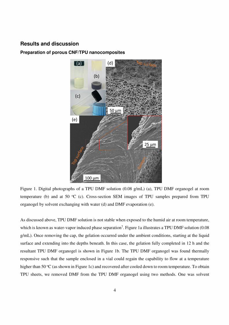
Figure 2. (a) Schematic illustration of the pathway to prepare porous CNF/TPU nanocomposites by
solution casting. (b) Photographs of a self-standing CNF/TPU DMF organogel (0.3g/0.7g/15mL). SEM
images of TPU30: the cross section (c) and top surface (d). The inset of c is a photograph of TPU30.
6
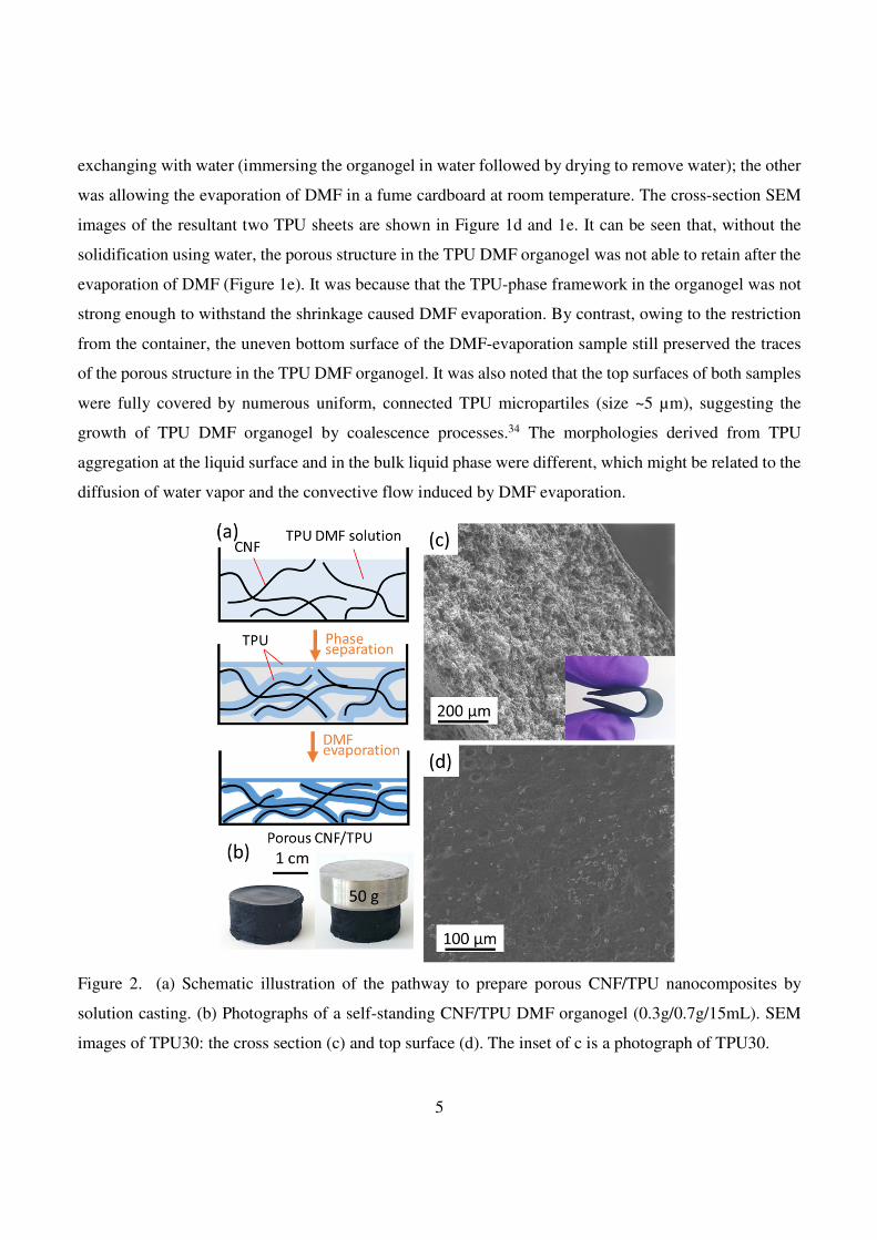
Figure 3. Cross-section SEM images of CNF/TPU nanocomposites: TPU10 (a, b), TPU20 (c, d), TPU30
(e, f), and TPU40 (g, h).
Rigid conductive fillers were proposed to cement the TPU-phase framework in the organogel so that
porous structures could be achieved using the conventional solution-casting method. Figure 2a illustrates
the pathway to utilize CNFs to reinforce the organogel and prepare porous CNF/TPU nanocomposites
directly by solution casting. The obtained CNF/TPU DMF organogel was quite strong as shown in Figure
2b. After removing DMF through evaporation, the resultant CNF/TPU nanocomposite sheets were porous
7
and flexible, as shown in Figure 2c. It can be seen from Figure 2d that the top surface of CNF/TPU
nanocomposites was smoother than that of the neat TPU sample as shown in Figure 1e. This indicates the
presence of CNFs significantly suppressed the formation of TPU microparticles at the liquid surface
because they spatially blocked the coalescence of small TPU nucleus particles.34 A set of CNF/TPU
nanocomposites with various CNF loadings (i.e. 10, 20, 30 and 40 wt.%) were prepared using this method.
Their porous structures were investigated by SEM, as shown in Figure 3. The straight wires in SEM
images are individual CNFs. The CNF/TPU nanocomposite with 10 wt.% CNF (TPU10) exhibited
underdeveloped porous structures (Figure 3a,b), indicating that the CNF-reinforced TPU framework at 10
wt.% CNF loading was not able to fully withstand the shrinkage caused DMF evaporation. With further
increasing CNF loading, the porous structures in CNF/TPU nanocomposites became well-developed.
From Figure 3(c-h), TPU20, TPU30 and TPU40 showed a well-defined open-cell structure and the pore
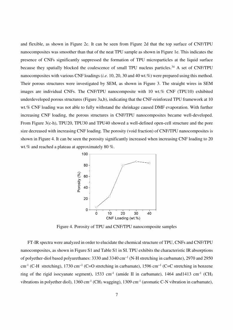
size decreased with increasing CNF loading. The porosity (void fraction) of CNF/TPU nanocomposites is
shown in Figure 4. It can be seen the porosity significantly increased when increasing CNF loading to 20
wt.% and reached a plateau at approximately 80 %.
Figure 4. Porosity of TPU and CNF/TPU nanocomposite samples
FT-IR spectra were analyzed in order to elucidate the chemical structure of TPU, CNFs and CNF/TPU
nanocomposites, as shown in Figure S1 and Table S1 in SI. TPU exhibits the characteristic IR absorptions
of polyether-diol based polyurethanes: 3330 and 3340 cm−1 (N-H stretching in carbamate), 2970 and 2950
cm-1 (C-H stretching), 1730 cm−1 (C=O stretching in carbamate), 1596 cm−1 (C=C stretching in benzene
ring of the rigid isocyanate segment), 1533 cm-1 (amide II in carbamate), 1464 and1413 cm-1 (CH2
vibrations in polyether diol), 1360 cm-1 (CH3 wagging), 1309 cm-1 (aromatic C-N vibration in carbamate),
8
1254 cm-1 (amide III in carbamate), 1221 and 1160 cm−1 (C-O-C stretching in polyether diol)35,36. It was
noted that TPU showed only one well-defined peak at 1730 cm−1, corresponding to free C=O37, indicating
most of carbonyl groups in TPU were not involved in hydrogen bonding. For TPU cast from its THF
solution, 56% of carbonyl groups were involved in hydrogen bonding37. The difference in the hydrogen-
bonding state of carbonyl groups might be related to the solvent used for solution casting. CNFs show no
obvious IR absorption peaks and the percent transmittance monotonically increases with the wavenumber
decreasing, due to their highly graphitic structure, which is in great agreement with previous report38. The
percent transmittance was significantly reduced with the introduction of CNFs and decreased with
increasing CNF loading. Resonant Mie scattering (RMieS) was observed39-41, indicated by the pronounced
oscillation of the baseline around 1740 and 2970 cm−1. This suggests the thickness of TPU phase coated on
CNFs decreased with increasing CNF loading which is consistent with the SEM observations.
Mechanical properties of porous CNF/TPU nanocomposites
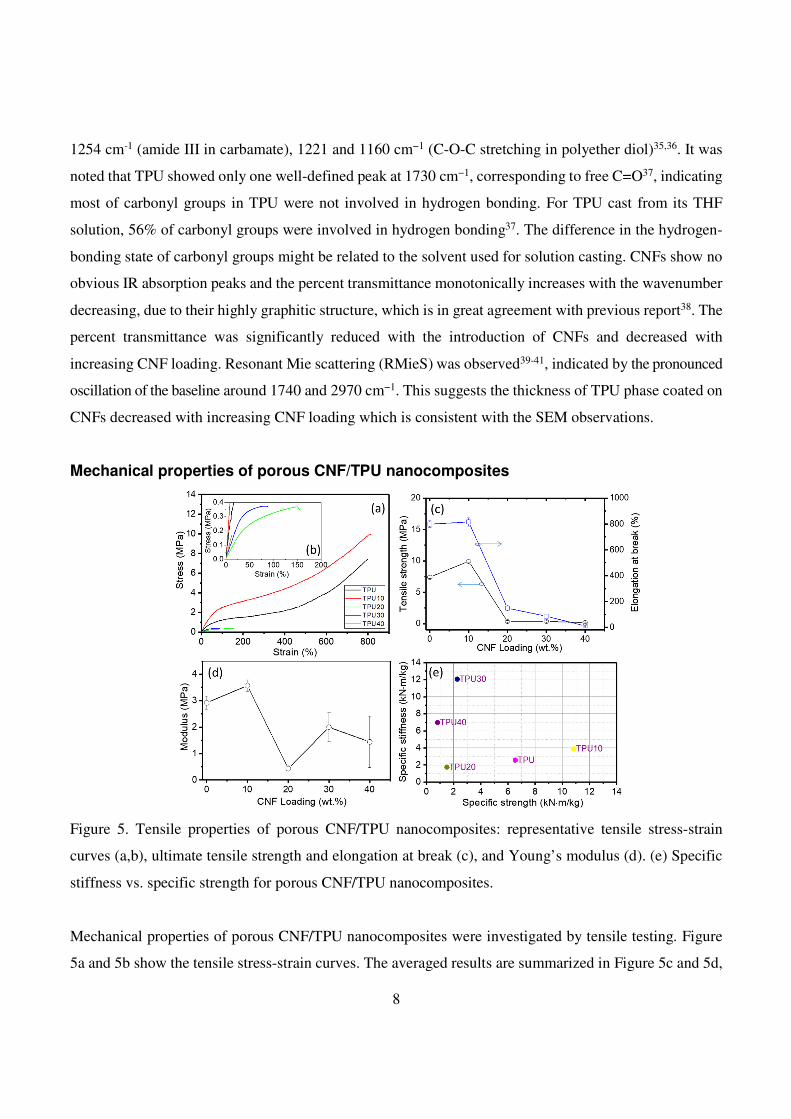
Figure 5. Tensile properties of porous CNF/TPU nanocomposites: representative tensile stress-strain
curves (a,b), ultimate tensile strength and elongation at break (c), and Young’s modulus (d). (e) Specific
stiffness vs. specific strength for porous CNF/TPU nanocomposites.
Mechanical properties of porous CNF/TPU nanocomposites were investigated by tensile testing. Figure
5a and 5b show the tensile stress-strain curves. The averaged results are summarized in Figure 5c and 5d,
9
with the error bars referring to standard deviations. TPU is not an ideal linear viscoelastic material, where
the modulus changes with the strain42. Ultimate tensile strength, elongation at break, and Young’s modulus
(at initial linear stage) were 7.41 MPa, 798%, and 2.92 MPa for neat TPU, respectively. In comparison to
neat TPU, tensile strength and Young’s modulus of TPU10 (with a porosity of 24.3%) were raised by 34%
and 22%, respectively, due to the reinforcement effect of CNFs. For highly porous samples, namely
TPU20 (80.1% porosity), TPU30 (87.3% porosity) and PU40 (84.5% porosity), their tensile strength and
Young’s modulus were remarkably lower than that of neat TPU and TPU10 owing to high porosity. It was
noticed that there was no clear trend in the Young’s modulus. This was caused by the fact that a higher
CNF loading is expected to lead to a higher Young’s modulus in its non-porous TPU nanocomposite; yet
the Young’s modulus of a porous nanocomposite is also inversely affected by the porosity which is again
dependent on the CNF loading. The values of elongation at break were 810%, 149%, 87% and 12% for
TPU10, TPU20, TPU30 and TPU40, respectively. The dramatic decline in elongation at break from
TPU10 to TPU20 can be explained by the fact that the latter had a much higher porosity which reduced
the uniformity of the material, resulting in more defects and other stress concentrations. Although these
values were lower than that of neat non-porous TPU, the mechanical performance of TPU20, TPU30 and
TPU40 was commendable considering such high porosities. Specific stiffness and specific strength of
samples are shown in Figure 5e. It can be seen that TPU30 presented the best stiffness-to-weight ratio
while TPU10 showed the best strength-to-weight ratio.
Electrical properties of porous CNF/TPU nanocomposites
The CNF network provides a continuous conductive network in the insulating TPU matrix. The
experimentally determined electrical conductivity (σ) increases with the CNF loading, from 2.66×10⁻³
S/cm with 10 wt.% CNFs to 2.98×10⁻² S/cm with 40 wt% CNFs (Figure 6a). It was found that the
resistance of CNF/TPU nanocomposites changed under stretching. At 50% stain, the resistance was raised
by 17.2 and 1.7 times for TPU10 and TPU20, respectively. The increment at 30% stain was 5.0, 0.8 and
1.7 times for TPU10, TPU20 and TPU30, respectively. It suggests that highly porous samples, TPU20
and TPU30, exhibited less sensitive dependence on strain, in comparison with TPU10. This means the
high porosity could significantly reduce the interference of stretching operations on the conductivity and
benefit the stability of the electrical conductive performance of materials in the application of flexible
electronics.
10
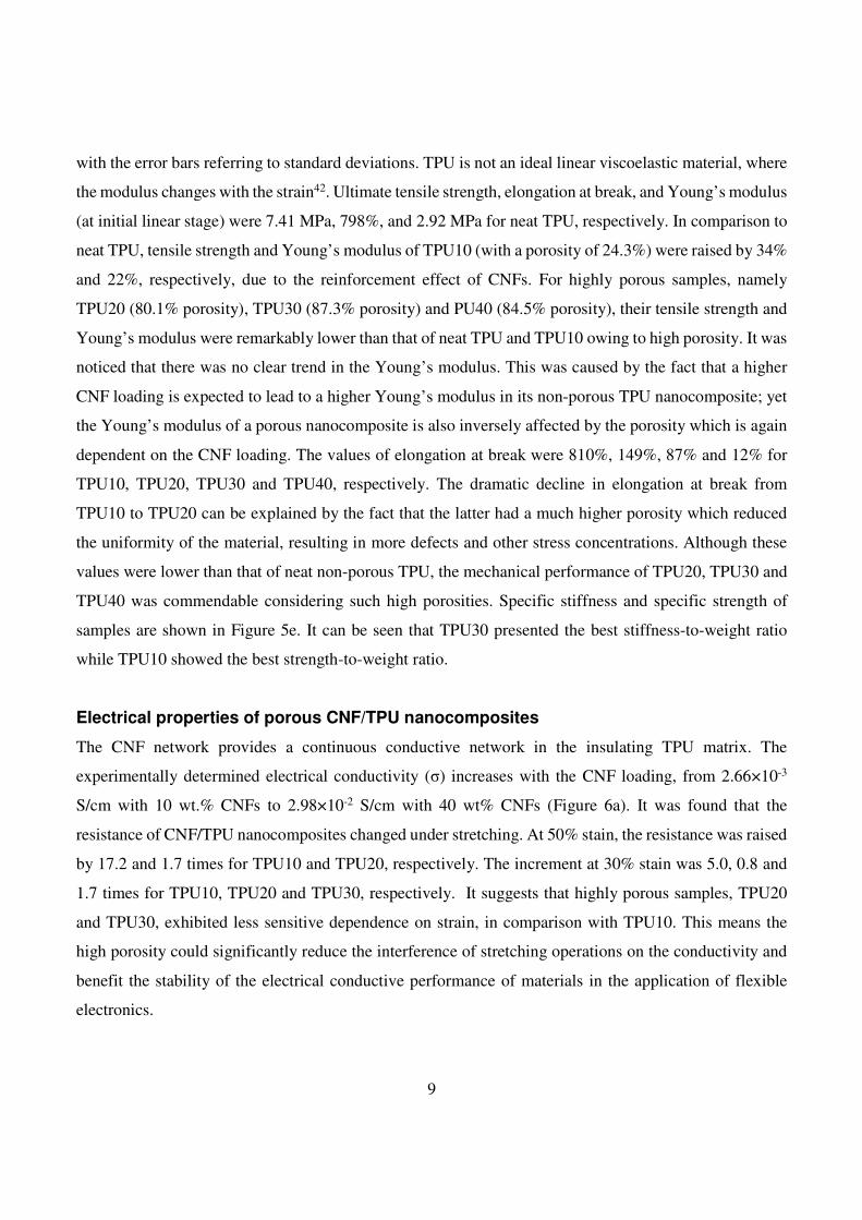
Figure 6. (a) Electrical conductivity of CNF/TPU nanocomposites versus the CNF loading. (Inset)
Demonstration of the electrically conductive property of TPU40 in an LED circuit. (b) The normalized
resistance (R/R0) of CNF/TPU nanocomposites as a function of strain. (c) R/R0 of CNF/TPU
nanocomposites as a function of time at different strains as represented by percentages in blue.
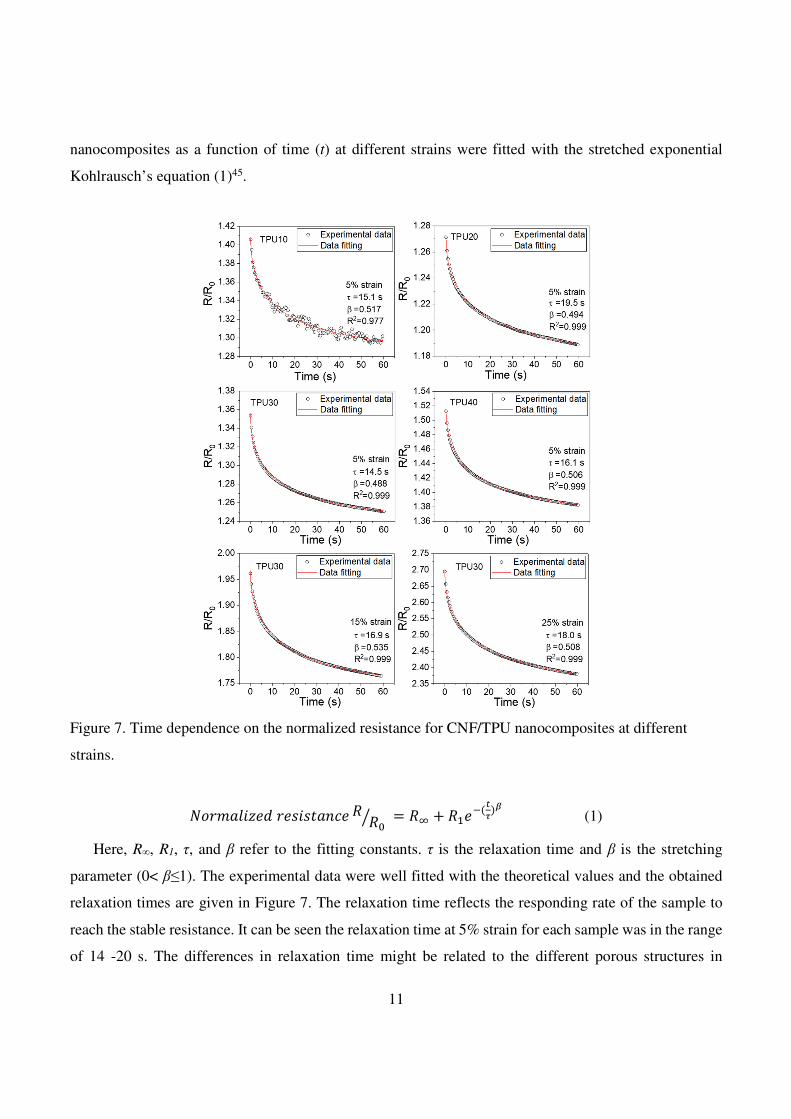
The relaxation behavior of each sample at different strains is shown in Figure 6c. The sample was
stretched to a desired strain (e.g., 5% and 10%) at a speed of 50 mm/min and then waited for 1 min before
further stretching. It is apparent that all the samples had a remarkable creep and the relaxation amplitude
increased with increasing strain. Taking TPU30 for an example, the relative resistance relaxed by 0.11 at
5% strain and 0.35 at 30% strain. This overshoot behavior was commonly observed in conductive
elastomer composites43,44. This was caused by the relaxation of conductive networks in conductive
elastomer nanocomposites, which was expected to be controlled by the relaxation behavior of elastomer
matrix. Therefore, to determine the relaxation time, the experimental relaxation curves of the CNF/TPU
11
nanocomposites as a function of time (t) at different strains were fitted with the stretched exponential
Kohlrausch’s equation (1)45.
Figure 7. Time dependence on the normalized resistance for CNF/TPU nanocomposites at different
strains.
������������ ��� � ��� � �� � ����
����
(1)
Here, R∞, R1, τ, and β refer to the fitting constants. τ is the relaxation time and β is the stretching
parameter (0< β≤1). The experimental data were well fitted with the theoretical values and the obtained
relaxation times are given in Figure 7. The relaxation time reflects the responding rate of the sample to
reach the stable resistance. It can be seen the relaxation time at 5% strain for each sample was in the range
of 14 -20 s. The differences in relaxation time might be related to the different porous structures in
12
nanocomposites and the different CNF loadings. The relaxation time increased with increasing strain (For
TPU30, the relaxation time was 14.5 s at 5% strain, 16.9 s at 15% strain, and 18.0 s at 25% strain), because
of the non-equilibrium rate dependent response of TPU. That is consistent with previous studies on stress
relaxation behavior of TPU4,46.
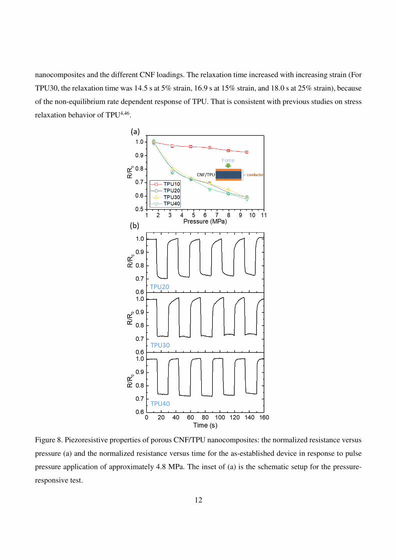
Figure 8. Piezoresistive properties of porous CNF/TPU nanocomposites: the normalized resistance versus
pressure (a) and the normalized resistance versus time for the as-established device in response to pulse
pressure application of approximately 4.8 MPa. The inset of (a) is the schematic setup for the pressure-
responsive test.
13
Conductive elastomer composites usually demonstrate the piezoresistive effect, owing to the raised
electrical conductivity caused by the compression-induced reduction in the thickness of insulating
polymer layer47. The piezoresistive effect in CNF/TPU nanocomposites was investigated, as shown in
Figure 8a. The device setup with a sandwich configuration was shown in the inset of Figure 10a. As
anticipated, the resistance of TPU10 decreased with increasing pressure in the range from 1.6 MPa
pressure up to 9.5 MPa. The resistance was reduced by ~10% at 9.5 MPa. Highly porous CNF/TPU
nanocomposites (i.e., TPU20, TPU30 and TPU40) demonstrated stronger piezoresistive effects in
comparison to TPU10. For instance, the resistance reductions for TPU20, TPU30 and TPU40 were
approximately 40% at 9.5 MPa. To demonstrate repeatability of the piezoresistive behavior, dynamic
pressure sensitivity was monitored while measuring the resistance variations with the repeated application
of ~4.8 MPa for five cycles (Figure 8b). Under a compression of ~4.8 MPa, the measured resistance
becomes noticeably lower; once the force was released, the resistance gradually increased to the initial
value. The as-established device exhibited a significant change in the resistance and good reproducible
dynamic responses.
Conclusions
Porous conductive TPU nanocomposites were successfully prepared by a conventional solution-casting
method. As a rigid conductive filler with high aspect ratio, CNFs were utilized to cement the porous
structure in the water vapor-induced TPU organogel. The CNF loading played an important role in the
formation of final porous structures in TPU nanocomposites. With a CNF loading lower than 10 wt.%,
the CNT-reinforced TPU-phase framework was not strong enough to withstand the shrinkage caused by
DMF evaporation. With increasing CNF loading higher than 20 wt.%, the porous structures in TPU
nanocomposites became well-developed. The porosity significantly increased with increasing CNF
loading to 20 wt.% and reached a plateau at approximately 80%. The electrical conductivity of TPU
nanocomposites increased with the CNF loading. The highest conductivity was achieved as 2.98×10⁻²
S/cm with 40 wt.% CNFs. The conductivity for all nanocomposite samples exhibited relaxation behavior
due to the viscoelasticity of TPU elastomer. The mechanical properties of highly porous samples were
different from the solid samples. TPU30 presented the best specific stiffness. All nanocomposite samples
showed piezoresistive behavior. Highly porous CNF/TPU nanocomposites demonstrated stronger
piezoresistive effect in comparison to TPU10, exhibiting good reproducible dynamic responses in
14
dynamic tests. This study provides a novel and facile approach to produce lightweight conductive polymer
films which have potential in pressure sensors, electromagnetic interference shielding, and filtration
membranes.
Methods
Materials
Thermoplastic polyurethane elastomer (IROGRAN PS 455-203) was obtained from Huntsman, which has
a Shore A hardness of 78 and density of 1.19 g/cm3. Carbon nanofibers (outer diameter: 100 nm and
length: 20-200µm) and N,N-dimethylformamide (99.8%) were purchased from Sigma-Aldrich. All
materials were used as received.
Preparation of porous CNF/TPU nanocomposites
CNF/TPU nanocomposites with various concentrations were prepared by solution blending followed by
solution casting. Firstly, CNFs (0.3 g) were dispersed into 15 mL DMF by sonication in an ultrasonic
bath (Fisherbrand 15051) for 30 min. Then, a desired amount of TPU was weighed and dissolved in the
suspension under magnetically stirring for 5 hours. The resultant mixture was poured into a
polytetrafluoroethylene (PTFE) dish and was kept in a fume cupboard for 2 h to allow the formation of
TPU DMF organogel at a relative humidity of ~80% and for another 22 h to allow the evaporation of
DMF. The residual solvent was removed in vacuum at 40 oC for 24 h. The residual solvent was removed
in vacuum at 40 oC for 24 h. Samples with 0%, 10%, 20%, 30% and 40% mass percentages of CNFs were
obtained by this method and designated as TPU, TPU10, TPU20, TPU30 and TPU40, respectively.
Characterization
Attenuated total reflectance-Fourier transform infrared (ATR-FTIR) spectroscopy was carried out on a
Frontier Optica spectrophotometer (PerkinElmer). The wavenumber region was between 4000 to 600 cm−1
with a resolution of 1 cm−1. The cross-section and top surface of TPU and CNF/TPU nanocomposites
were investigated by scanning electron microscopy (SEM) on Inspect F (FEI) using a 10 kV acceleration
voltage. For cross-sectional imaging, the samples were fractured in liquid nitrogen and coated with gold
prior to SEM observations. Tensile tests were carried out at room temperature (25 oC) on a Hounsfield
universal testing machine (Tinius Olsen Ltd.), where a 10 N load cell and a 100 mm/min testing speed
were employed. For each sample, five specimens were tested. The electrical properties of the sample were
15
monitored using 4-point probes method via a benchtop Agilent 34401A multimeter (Keysight
Technologies Inc.). For the conductivity test, a disk-like sample (Φ16 mm) was used and contacted to the
circuit via two plate aluminium electrodes. For the piezoresistivity measurement, the resistance of the
sample was recorded under various external pressures applied by the Hounsfield universal testing machine.
The porosity (void fraction) of samples was calculated from the true density measured on AccuPyc-II-
1340 pycnometer (Micromeritics Instrument Corp.) and the bulk density.
Data Availability Statement
The datasets generated during and/or analysed during the current study are available from the
corresponding author on reasonable request and shared in Zenodo repository.
Acknowledgements
This work was supported by the European commission’s horizon 2020 research and innovation
programme [Grant Number: 656467 — SUPRONICS — H2020-MSCA-IF-2014].
Author Contributions
T.W. conducted all experiments and data analysis. T.W. and B.C. designed the experiments and wrote
the paper.
Additional Information
Competing Interests
The authors declare that they have no competing interests.
Electronic supplementary material
Supplementary information
References
1 Buckley, C. P., Prisacariu, C. & Martin, C. Elasticity and inelasticity of thermoplastic polyurethane
elastomers: Sensitivity to chemical and physical structure. Polymer 51, 3213-3224 (2010).
2 Liu, C., Qin, H. & Mather, P. T. Review of progress in shape-memory polymers. J. Mater. Chem. 17,
1543-1558 (2007).
16
3 Hassan, M. K., Mauritz, K. A., Storey, R. F. & Wiggins, J. S. Biodegradable aliphatic thermoplastic
polyurethane based on poly(ε-caprolactone) and L-lysine diisocyanate. J. Polym. Sci., Part A: Polym.
Chem. 44, 2990-3000 (2006).
4 Qi, H. J. & Boyce, M. C. Stress–strain behavior of thermoplastic polyurethanes. Mech. Mater. 37,
817-839 (2005).
5 Guan, J., Fujimoto, K. L., Sacks, M. S. & Wagner, W. R. Preparation and characterization of highly
porous, biodegradable polyurethane scaffolds for soft tissue applications. Biomaterials 26, 3961-3971
(2005).
6 Gurunathan, T., Rao, C. R. K., Narayan, R. & Raju, K. V. S. N. Polyurethane conductive blends and
composites: synthesis and applications perspective. J. Mater. Sci. 48, 67-80 (2013).
7 Chen, Y., Li, Y., Xu, D. & Zhai, W. Fabrication of stretchable, flexible conductive thermoplastic
polyurethane/graphene composites via foaming. RSC Adv. 5, 82034-82041 (2015).
8 Novák, I., Krupa, I. & Chodák, I. Investigation of the correlation between electrical conductivity and
elongation at break in polyurethane-based adhesives. Synth. Met. 131, 93-98 (2002).
9 O'Brien, F. J. Biomaterials & scaffolds for tissue engineering. Mater. Today 14, 88-95 (2011).
10 Zhao, X. S., Bao, X. Y., Guo, W. & Lee, F. Y. Immobilizing catalysts on porous materials. Mater.
Today 9, 32-39 (2006).
11 Ulbricht, M. Advanced functional polymer membranes. Polymer 47, 2217-2262 (2006).
12 Baetens, R., Jelle, B. P. & Gustavsen, A. Aerogel insulation for building applications: A state-of-the-
art review. Energy Build. 43, 761-769 (2011).
13 Gui, X. et al. Carbon nanotube sponges. Adv. Mater. 22, 617-621 (2010).
14 Olson, H. F. & May, E. G. Electronic Sound Absorber. J. Acoust. Soc. Am. 25, 1130-1136 (1953).
15 Gupta, T. K., Singh, B. P., Dhakate, S. R., Singh, V. N. & Mathur, R. B. Improved nanoindentation
and microwave shielding properties of modified MWCNT reinforced polyurethane composites. J.
Mater. Chem. A 1, 9138-9149 (2013).
16 Fan, Y. J. et al. Stretchable porous carbon nanotube-elastomer hybrid nanocomposite for harvesting
mechanical energy. Adv. Mater. 29, 1603115 (2017).
17 Liu, H. et al. Lightweight conductive graphene/thermoplastic polyurethane foams with ultrahigh
compressibility for piezoresistive sensing. J. Mater. Chem. C 5, 73-83 (2017).
18 Ito, S., Matsunaga, K., Tajima, M. & Yoshida, Y. Generation of microcellular polyurethane with
supercritical carbon dioxide. J. Appl. Polym. Sci. 106, 3581-3586 (2007).
19 Dai, C., Zhang, C., Huang, W., Chang, K.-C. & Lee, L. J. Thermoplastic polyurethane microcellular
fibers via supercritical carbon dioxide based extrusion foaming. Polym. Eng. Sci. 53, 2360-2369
(2013).
20 Fromstein, J. D. & Woodhouse, K. A. Elastomeric biodegradable polyurethane blends for soft tissue
applications. J. Biomater. Sci., Polym. Ed. 13, 391-406 (2002).
21 Khorasani, M. T. & Shorgashti, S. Fabrication of microporous thermoplastic polyurethane for use as
small-diameter vascular graft material. I. Phase-inversion method. J. Biomed. Mater. Res. Part B Appl.
Biomater 76B, 41-48 (2006).
22 Polat, Y. et al. Solution blowing of thermoplastic polyurethane nanofibers: A facile method to
produce flexible porous materials. J. Appl. Polym. Sci. 133, 43025 (2016).
23 Mi, H. Y. et al. Approaches to fabricating multiple-layered vascular scaffolds using hybrid
electrospinning and thermally induced phase separation methods. Ind. Eng. Chem. Res. 55, 882-892
(2016).
24 Yuan, S. et al. 3D soft auxetic lattice structures fabricated by selective laser sintering: TPU powder
evaluation and process optimization. Mater. Des. 120, 317-327 (2017).
17
25 Dasdemir, M., Topalbekiroglu, M. & Demir, A. Electrospinning of thermoplastic polyurethane
microfibers and nanofibers from polymer solution and melt. J. Appl. Polym. Sci. 127, 1901-1908
(2013).
26 Hacker, C., Karahaliloglu, Z., Seide, G., Denkbas, E. B. & Gries, T. Functionally modified, melt-
electrospun thermoplastic polyurethane mats for wound-dressing applications. J. Appl. Polym. Sci.
131, 40132 (2014).
27 Mi, H. Y., Jing, X., Jacques, B. R., Turng, L. S. & Peng, X. F. Characterization and properties of
electrospun thermoplastic polyurethane blend fibers: Effect of solution rheological properties on fiber
formation. J. Mater. Res. 28, 2339-2350 (2013).
28 Li, Z. et al. Selective laser sintering 3D printing: A way to construct 3d electrically conductive
segregated network in polymer matrix. Macromol. Mater. Eng., 1700211 (2017).
29 Hou, Y., Duan, L., Gui, Z. & Hu, Y. An infiltration method to synthesize thermoplastic polyurethane
composites based on size-controlled graphene foams. Composites Part A 97, 67-75 (2017).
30 Rizvi, R. & Naguib, H. Development and characterization of piezoresistive porous TPU-MWNT
nanocomposites. AIP Conf. Proc. 1593, 383-387 (2014).
31 Liu, H. et al. Piezoresistive behavior of porous carbon nanotube-thermoplastic polyurethane
conductive nanocomposites with ultrahigh compressibility. Appl. Phys. Lett. 108, 011904 (2016).
32 Wei, X. et al. Conductive herringbone structure carbon nanotube/thermoplastic polyurethane porous
foam tuned by epoxy for high performance flexible piezoresistive sensor. Compos. Sci. Technol. 149,
166-177 (2017).
33 Guillen, G. R., Pan, Y., Li, M. & Hoek, E. M. V. Preparation and characterization of membranes
formed by nonsolvent induced phase separation: A review. Ind. Eng. Chem. Res. 50, 3798-3817
(2011).
34 Li, M. et al. Controlling the microstructure of poly(vinylidene-fluoride) (PVDF) thin films for
microelectronics. J. Mater. Chem. C 1, 7695-7702 (2013).
35 Luo, N., Wang, D. N. & Ying, S. K. Hydrogen-bonding properties of segmented polyether
poly(urethane urea) copolymer. Macromolecules 30, 4405-4409 (1997).
36 Todros, S., Venturato, C., Natali, A. N., Pace, G. & Di Noto, V. Effect of steam on structure and
mechanical properties of biomedical block copolymers. J. Polym. Sci., Part B: Polym. Phys. 52, 1337-
1346 (2014).
37 Seymour, R. W., Estes, G. M. & Cooper, S. L. Infrared studies of segmented polyurethan elastomers.
I. Hydrogen bonding. Macromolecules 3, 579-583 (1970).
38 Huang, S. et al. Reinforcing Nylon 6 via surface-initiated anionic ring-opening polymerization from
stacked-cup carbon nanofibers. Compos. Sci. Technol. 93, 30-37 (2014).
39 Miljkovic, M., Bird, B. & Diem, M. Line shape distortion effects in infrared spectroscopy. Analyst
137, 3954-3964 (2012).
40 Dazzi, A., Deniset-Besseau, A. & Lasch, P. Minimising contributions from scattering in infrared
spectra by means of an integrating sphere. Analyst 138, 4191-4201 (2013).
41 Bassan, P. et al. Resonant Mie scattering in infrared spectroscopy of biological materials -
understanding the 'dispersion artefact'. Analyst 134, 1586-1593 (2009).
42 Sain, T., Meaud, J., Yeom, B., Waas, A. M. & Arruda, E. M. Rate dependent finite strain constitutive
modeling of polyurethane and polyurethane–clay nanocomposites. Int. J. Solids. Struct. 54, 147-155
(2015).
43 Mattmann, C., Clemens, F. & Tröster, G. Sensor for measuring strain in textile. Sensors 8, 3719
(2008).
18
44 Morteza, A., Yong Jin, Y. & Inkyu, P. Ultra-stretchable and skin-mountable strain sensors using
carbon nanotubes–Ecoflex nanocomposites. Nanotechnology 26, 375501 (2015).
45 Ponnamma, D. et al. Interrelated shape memory and Payne effect in polyurethane/graphene oxide
nanocomposites. RSC Adv. 3, 16068-16079 (2013).
46 Cellini, F., Khapli, S., Peterson, S. D. & Porfiri, M. Mechanochromic polyurethane strain sensor. Appl.
Phys. Lett. 105, 061907 (2014).
47 Chen, L., Chen, G. H. & Lu, L. Piezoresistive behavior study on finger-sensing silicone
rubber/graphite nanosheet nanocomposites. Adv. Funct. Mater. 17, 898-904 (2007).