Façade Shading Analysis - City of Melbourne · Façade Shading Analysis Prepared by: Advanced...
26
Façade Shading Analysis Prepared by: Advanced Environmental Concepts Pty Ltd ACN 075 117 243 Level 1, 41 McLaren Street North Sydney NSW 2060 design advice passive systems design analysis low energy services April 08 AESY820000\0\2\MCP30303\Draft.0 Prepared for: Melbourne City Council Client address Client address 2 Client address 3 Melbourne City Council
Transcript of Façade Shading Analysis - City of Melbourne · Façade Shading Analysis Prepared by: Advanced...

Façade Shading Analysis
Prepared by: Advanced Environmental Concepts Pty Ltd ACN 075 117 243 Level 1, 41 McLaren Street North Sydney NSW 2060
design advice
passive systems
design analysis
low energy services
April 08
AESY820000\0\2\MCP30303\Draft.0
Prepared for: Melbourne City Council Client address Client address 2 Client address 3
Melbourne City Council

Façade Shading Analysis © Advanced Environmental Concepts
Introduction AESY820000\0\2\MCP30303\Draft.0
II
1 EXECUTIVE SUMMARY This report has analysed the shading aspects of the new Melbourne City Council development from three different viewpoints. Firstly, stereographic diagrams demonstrating the effect of the surrounding buildings on the shading of each façade were produced. Next, each façade was analysed, separate to the building context, to deduce what levels of horizontal and vertical shading are required to provide greater than 95% shading. These conclusions were then refined by considering the shading of the surrounding buildings to produce greater than 95% shading. Finally, a critical appraisal of the current design with respect to the shading was undertaken and recommendations given.

Façade Shading Analysis © Advanced Environmental Concepts
Table of ContentsIntroduction AESY820000\0\2\MCP30303\Draft.0
III
TABLE OF CONTENTS 1 EXECUTIVE SUMMARY II
TABLE OF CONTENTS III
LIST OF FIGURES IV
2 INTRODUCTION 1
3 APPROACH 2
3.1 Horizontal shading devices 3 3.2 Vertical shading devices 4
4 PRELIMINARY RESULTS 5
5 FURTHER ANALYSIS 6
5.1 Surrounding Shading 6 5.2 Fixed Shading Elements 9
6 CURRENT DESIGN ANALYSIS 16
7 CONCLUSION 22
Date 14/3/03
Revision and Status Final
Author MCP
Project Team Leader MMC

Façade Shading Analysis © Advanced Environmental Concepts
List of FiguresIntroduction AESY820000\0\2\MCP30303\Draft.0
IV
LIST OF FIGURES Figure 1 - Horizontal Shading Ratios 3 Figure 2 - Vertical Shading Ratios 4 Figure 3 - Preliminary Results 5 Figure 4 - North Facade - 2x + 2y 9 Figure 5 - North Facade 0.8x + 0.8y 10 Figure 6 - East Facade - 0.25x + 0.25y 11 Figure 7 - East Facade - 0.65x + 0.65y 12 Figure 8 – South Façade - 0.5x + 0.35y 13 Figure 9 - West Facade - 2.3x + 1.9y 14 Figure 10 - Final Recommendations 15 Figure 11 - East Facade with 2.4 metres shading horizontally and vertically 17 Figure 12 - Shading elements for South facade 18 Figure 13 - South facade shading required 19 Figure 14 - Shading elements for North facade 20 Figure 15 - North facade shading required 21 Figure 16 - Final Recommendations 22

Façade Shading Analysis © Advanced Environmental Concepts
Introduction AESY820000\0\2\MCP30303\Draft.0
1
2 INTRODUCTION This report assesses the sun penetration at each façade of the proposed Melbourne City Council development. Key dates were chosen in the year and the ensuing analysis deduced the extent of vertical and horizontal shading required for 100% shading. These results were then refined in the context of the building’s location and hence shading provided from the surrounding structures.

Façade Shading Analysis © Advanced Environmental Concepts
Approach AESY820000\0\2\MCP30303\Draft.0
2
3 APPROACH In order to obtain the correct shading devices that will limit sun penetration on the external windows, a detailed sun analysis has been performed. This sun analysis considers the sun penetration for the following days of the year:
• December 22 (Summer solstice) • March 22 (Autumn Equinox) • June 22 (Winter solstice)
The solstices were used as they represent the extreme cases of the sun’s path, i.e. the summer solstice occurs when the altitude of the sun is at its highest and conversely the winter solstice occurs when the altitude of the sun in the middle of the day is at its lowest. This provides the full range of solar penetration, with all possibilities lying in between. The Autumn equinox is used to represent an endpoint to summer and possibly less stringent shading requirements. Conversely, November 1st is used to represent the beginning of summer for the same reason.

Façade Shading Analysis © Advanced Environmental Concepts
Approach AESY820000\0\2\MCP30303\Draft.0
3
3.1 Horizontal shading devices
Horizontal shading devices are represented as a function of window height (y). For example, the following diagram shows the ratio for a horizontal shading device to be 0.5y, where y is the window height. Thus, a 1metre high window will have a shading device of 0.5metres deep and a 2metre high window will have a shading device of 1metre depth.
Figure 1 - Horizontal Shading Ratios

Façade Shading Analysis © Advanced Environmental Concepts
Approach AESY820000\0\2\MCP30303\Draft.0
4
3.2 Vertical shading devices The vertical shading devices are represented as a function of the window width (x). For example, the diagram below shows a shading device of 0.5x, this means a 0.5metre deep vertical shading device for a 1 metre wide window or a 1metre deep shading device for a 2metre wide window.
Figure 2 - Vertical Shading Ratios

Façade Shading Analysis © Advanced Environmental Concepts
Approach AESY820000\0\2\MCP30303\Draft.0
5
4 PRELIMINARY RESULTS The results in the table below are shading ratios. All results give a larger than 95% shaded proportion of the window between the hours of 8am and 5pm.
North East South West
x y x Y x y x y
22-Dec 0.255 0.265 1.180 1.300 0.725 0.395 0.750 1.150
22-Mar 0.740 0.790 2.000 3.000 0.300 0.065 0.900 0.805
22-Jun 2.000 3.000 4.000 3.500 0.000 0.000 0.740 0.245
1-Nov 0.450 0.450 1.500 1.600 0.500 0.280 0.900 1.330 Figure 3 - Preliminary Results
For most of the year the facades can be suitably shaded with reasonable levels of shading. However, in certain instances, such as the east façade in winter-time, extensive shading is required, due to the low angle of the sun perpendicular to the window.

Façade Shading Analysis © Advanced Environmental Concepts
Approach AESY820000\0\2\MCP30303\Draft.0
6
5 FURTHER ANALYSIS To better model the building in its context, the following section analyses the amount of sun falling on the various facades, at different levels, by way of stereographic diagrams. Stereographic diagrams describe the sun or shade provided to a surface for all dates and times during the year. Shaded areas of the diagram show times when the façade is in shade, whilst the unshaded areas show areas of sun penetration. Firstly, stereographic diagrams showing shading from the surrounding buildings are generated. Stereographic diagrams are then generated showing the effect of the shading elements, and where possible this has been optimised to less shading than prescribed in Figure 3. Success can be measured when these two diagrams can be superimposed onto one another to successfully produce >95% shading for the hours 8am to 5pm.
5.1 Surrounding Shading Shade provided by the surrounding buildings is depicted in the diagrams on the following pages for levels 1 and 9, for the North, South, East and West facades.

Façade Shading Analysis © Advanced Environmental Concepts
Approach AESY820000\0\2\MCP30303\Draft.0
7
North Façade – Level One North Façade – Level Nine
East Façade – Level One East Façade – Level Nine

Façade Shading Analysis © Advanced Environmental Concepts
Approach AESY820000\0\2\MCP30303\Draft.0
8
South Façade – Level One South Façade – Level Nine
West Façade – Level One West Façade – Level Nine
Façade Shading Analysis © Advanced Environmental Concepts
Approach AESY820000\0\2\MCP30303\Draft.0
9
5.2 Fixed Shading Elements The following diagrams were optimised to compliment the above diagrams so that, as mentioned before, when the two are superimposed, the desired shading is obtained. This diagram was obtained for the North façade with a 2x + 2y shading scheme;
Figure 4 - North Facade - 2x + 2y

Façade Shading Analysis © Advanced Environmental Concepts
Approach AESY820000\0\2\MCP30303\Draft.0
10
Whereas Figure 4 shows year round shading, Figure 5 below shows that reducing the extent of shading to 0.8x + 0.8y can provide complete shading in the summer yet also allow afternoon solar penetration in the winter time.
Figure 5 - North Facade 0.8x + 0.8y

Façade Shading Analysis © Advanced Environmental Concepts
Approach AESY820000\0\2\MCP30303\Draft.0
11
This next diagram represents the shading seen by the eastern façade under a 0.25x + 0.25y shading scheme. This scheme would be suitable for complete shading on level one.
Figure 6 - East Facade - 0.25x + 0.25y

Façade Shading Analysis © Advanced Environmental Concepts
Approach AESY820000\0\2\MCP30303\Draft.0
12
Level Nine, however, would require more than twice the amount of shading. This next diagram represents the shading seen by the southern façade under a 0.65x + 0.65y scheme.
Figure 7 - East Facade - 0.65x + 0.65y

Façade Shading Analysis © Advanced Environmental Concepts
Approach AESY820000\0\2\MCP30303\Draft.0
13
This next diagram represents the shading seen by the southern façade under a 0.5x + 0.35y shading scheme.
Figure 8 – South Façade - 0.5x + 0.35y
Façade Shading Analysis © Advanced Environmental Concepts
Approach AESY820000\0\2\MCP30303\Draft.0
14
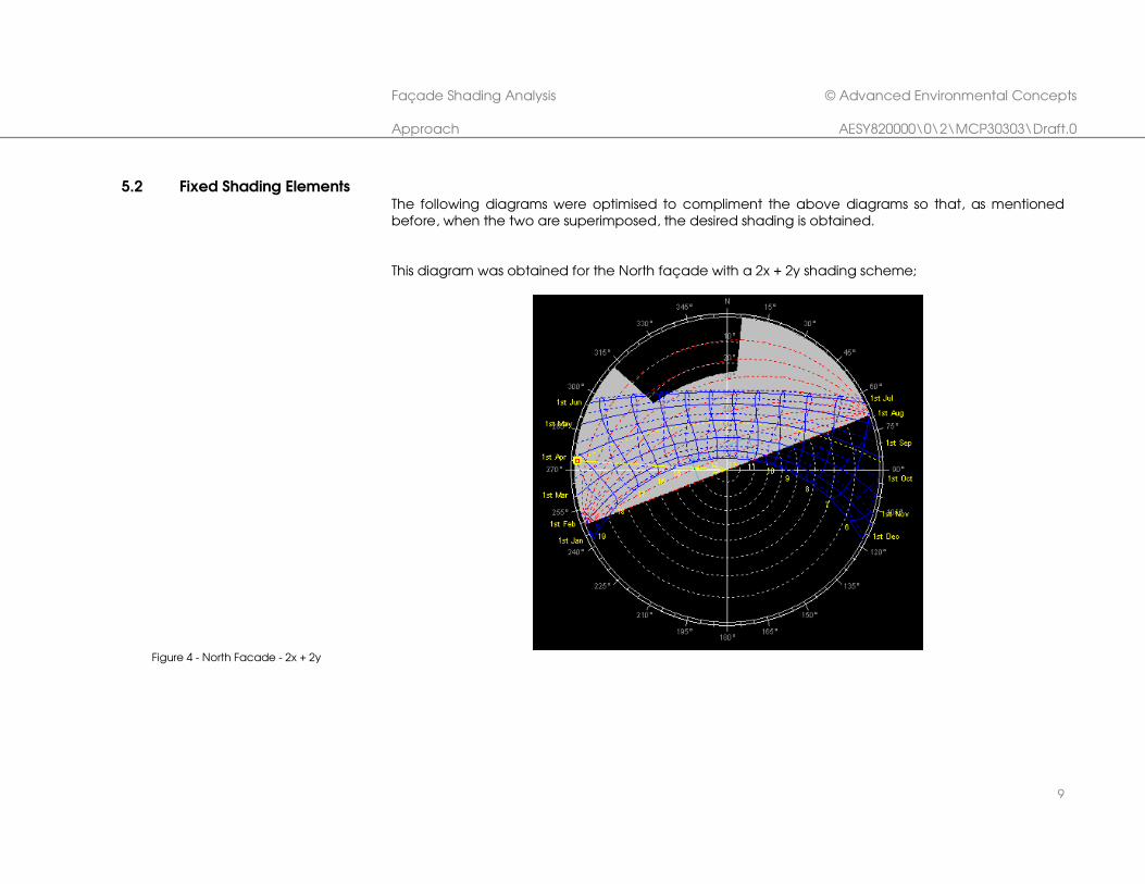
This next diagram represents the shading seen by the western façade under a 2.3x + 1.9y shading scheme.
Figure 9 - West Facade - 2.3x + 1.9y

Façade Shading Analysis © Advanced Environmental Concepts
Approach AESY820000\0\2\MCP30303\Draft.0
15
So as a minimum shading requirement to obtain greater than 95% shading of a window space, the following horizontal and vertical shading ratios are suggested:
Level 1 Level 9
Vertical Horizontal Vertical Horizontal
North (Summer only) 0.8 0.8 0.8 0.8
North (All year) 2 2 2 2
South 0.5 0.35 0.5 0.35
East 0.25 0.25 0.65 0.65
West 2.3 1.9 2.3 1.9 Figure 10 - Final Recommendations

Façade Shading Analysis © Advanced Environmental Concepts
Approach AESY820000\0\2\MCP30303\Draft.0
16
6 CURRENT DESIGN ANALYSIS
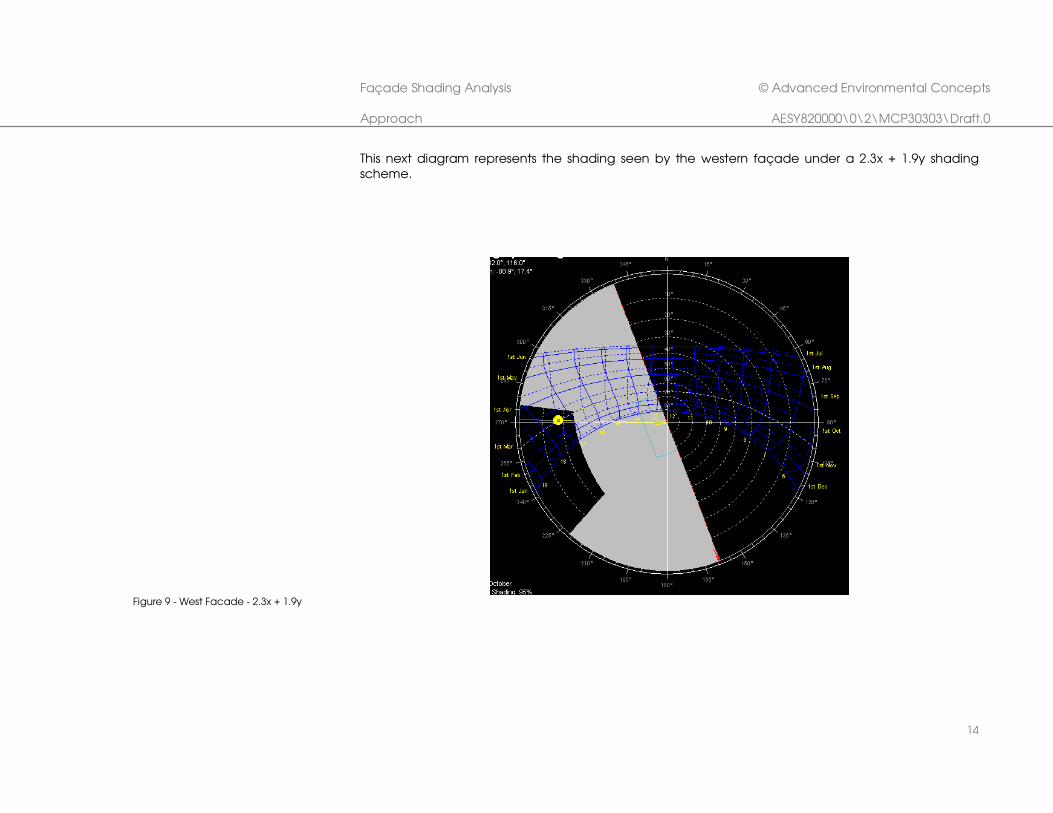
Equipped with the above knowledge, critical analysis of the current design can be made. The strongest suggestion from the above results is to have extensive vertical and horizontal shading on the western façade. Currently, the plans detail an operable louvre system to provide shading when it is needed in the late hours of the day but allows light to enter when not in direct line of the sun. The louvres are situated approximately 4.9 metres from any office space and would provide ample shading in this instance. The eastern façade is dominated by the toilet core and thus there is only a small area of glass façade where sun could actually penetrate. This area is protected by horizontal shading in the form of a balcony from the floor directly above it. The balcony has a width of 2.4 metres which creates a ratio of greater than 1 to 1 for horizontal shading. Referring to the table above, this is ample horizontal shading. The vertical shading specified is required to shade the façade during the winter months of May, June, July and August and only then in the middle of the day. This sun encroaches on the façade from the north and the toilet core provides 2.4 metres of shading to the 6.15 metre wide façade. This creates a ratio of 0.4 which would be sufficient for the first four floors but not so for the upper floors, though this solar penetration would be minimal. The diagram below shows the shading for the specified 2.4 metres of balcony and toilet core.
Façade Shading Analysis © Advanced Environmental Concepts
Approach AESY820000\0\2\MCP30303\Draft.0
17
Figure 11 - East Facade with 2.4 metres
shading horizontally and vertically

Façade Shading Analysis © Advanced Environmental Concepts
Approach AESY820000\0\2\MCP30303\Draft.0
18
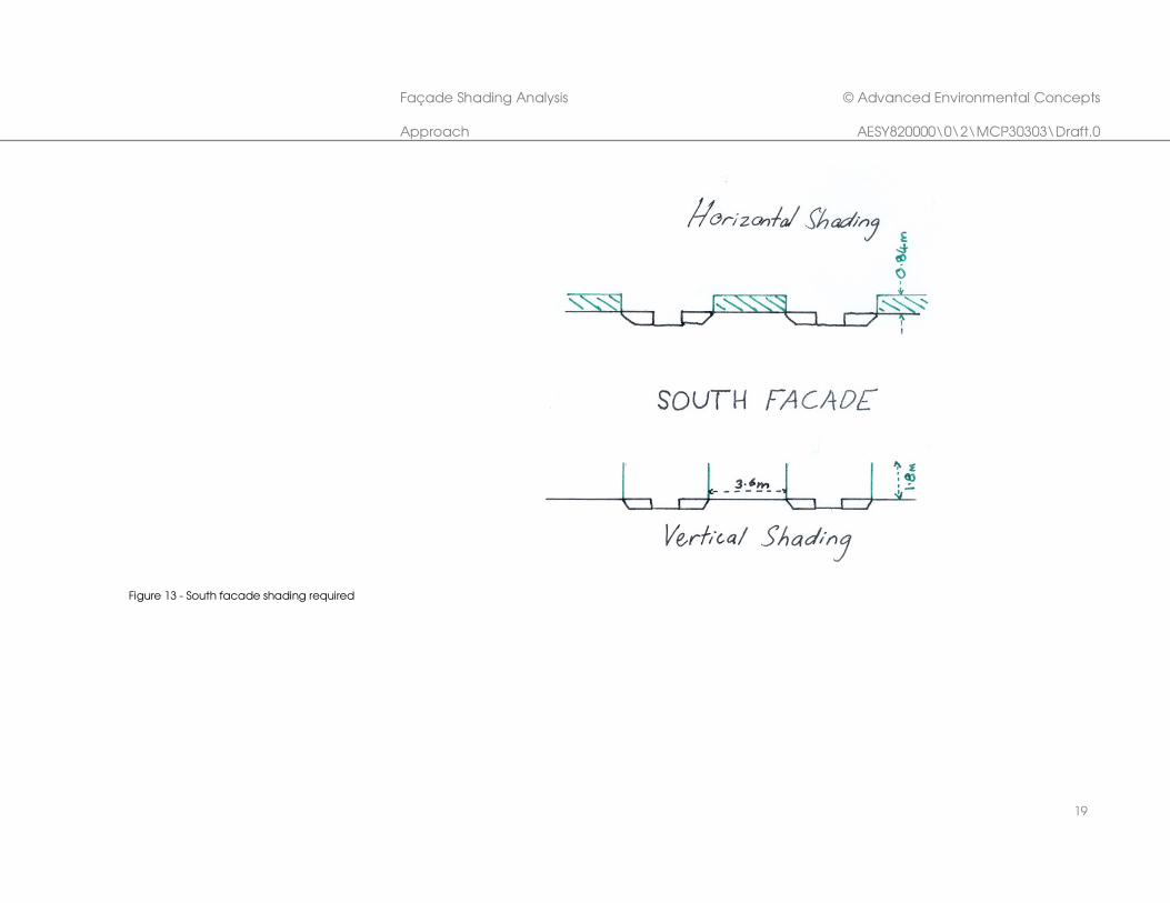
The southern façade currently has vertical shading elements of 1.6 metres depth that cover a window width of 3.8 metres. This provides us with a ratio of 0.42 for vertical shading. Reference to Figure 10 shows that this is not quite enough vertical shading and that a depth of 1.9 metres should be employed to attain complete shading. There appears to be no horizontal shading and this will result in less than 100% shading. Using the information given in Figure 10 we can derive the horizontal and vertical shading elements required on the southern façade for complete shading. We can take a typical floor where the horizontal shading is provided at a height of 2.4 metres and the window width is 3.6 metres. Referring to Figure 14 we can see the shading elements required for complete shading all year round and for summer only.
Horizontal Vertical
Ratio Shading (m) Ratio Shading (m)
South 0.35 0.84 0.5 1.8 Figure 12 - Shading elements for South facade
The information in Figure 12 is represented graphically by a sketch drawing in Figure 13.
Façade Shading Analysis © Advanced Environmental Concepts
Approach AESY820000\0\2\MCP30303\Draft.0
19
Figure 13 - South facade shading required

Façade Shading Analysis © Advanced Environmental Concepts
Approach AESY820000\0\2\MCP30303\Draft.0
20
The northern façade, on the other hand, currently has a 2.3 metre horizontal shading element above each window. This is approximately a 1 to 1 ratio for an average window height of approximately 2.5 metres. As seen in Figure 10 a ratio of 2 is required for year round shading and thus the current design is inadequate in this respect. It will however be satisfactory for summer horizontal shading given that only a ratio of 0.8 is required. The vertical shading required is also at a ratio of 2 to 1. Currently, the vertical shading extends to about 1 metre from the façade and must shade a variety of window widths, from 1.8 metres on level nine to 5 metres on level one. These window widths represent vertical shading ratios of 0.2 to 0.55 which is insufficient for complete shading, even for summer only. Using the information given in Figure 10 we can derive the horizontal and vertical shading elements required on the northern façade for complete shading. We can take a typical floor where the horizontal shading is provided at a height of 2.4 metres and the window width is 3.6 metres. Referring to Figure 14 we can see the shading elements required for complete shading all year round and for summer only.
Horizontal Vertical
Ratio Shading (m) Ratio Shading (m)
North (Summer only) 0.8 1.96 0.8 2.88
North (All year) 2 4.8 2 7.2 Figure 14 - Shading elements for North facade
The information in Figure 14 is represented graphically by a sketch drawing in Figure 13.

Façade Shading Analysis © Advanced Environmental Concepts
Approach AESY820000\0\2\MCP30303\Draft.0
21
Figure 15 - North facade shading required

Façade Shading Analysis © Advanced Environmental Concepts
Approach AESY820000\0\2\MCP30303\Draft.0
22
7 CONCLUSION This report has analysed the shading aspects of the new Melbourne City Council development from three different viewpoints. Firstly, stereographic diagrams demonstrating the effect of the surrounding buildings on the shading of each façade were produced. Next, each façade was analysed, separate to the building context, to deduce what levels of horizontal and vertical shading are required to provide greater than 95% shading. These conclusions were then refined by considering the shading of the surrounding buildings to produce greater than 95% shading. Finally, a critical appraisal of the current design with respect to the shading was undertaken and recommendations given (and repeated in the table below).
Level 1 Level 9
Vertical Horizontal Vertical Horizontal
North (Summer only) 0.8 0.8 0.8 0.8
North (All year) 2 2 2 2
South 0.5 0.35 0.5 0.35
East 0.25 0.25 0.65 0.65
West 2.3 1.9 2.3 1.9 Figure 16 - Final Recommendations