FABX1A-LE & FABX2A-LE
12
User Manual FABX1A-LE & FABX2A-LE Covering Models: 32100 & 32101 The models detailed within this document comply with ANSI Z359.14-2014, ANSI A10.32:2012, OSHA 1910 and OSHA 1926 Subpart M Requirements.
Transcript of FABX1A-LE & FABX2A-LE

User Manual
FABX1A-LE & FABX2A-LE
Covering Models:32100 & 32101
The models detailed within this document comply with ANSI Z359.14-2014, ANSI
A10.32:2012, OSHA 1910 and OSHA 1926 Subpart M Requirements.
User ManualPage 2
FABX1A-LE & FABX2A-LE
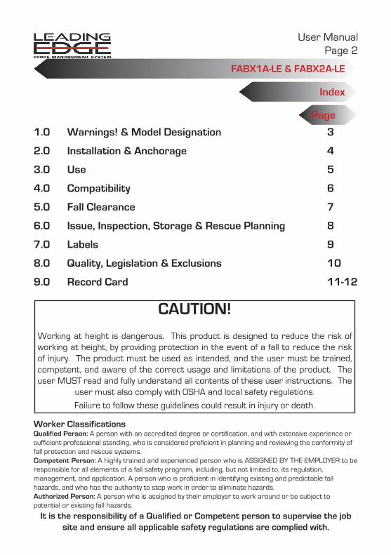
Index
Page
1.0 Warnings! & Model Designation
2.0 Installation & Anchorage
3.0 Use
4.0 Compatibility
5.0 Fall Clearance
6.0 Issue, Inspection, Storage & Rescue Planning
7.0 Labels
8.0 Quality, Legislation & Exclusions
9.0 Record Card
3
4
5
6
7
8
9
10
11-12
CAUTION!
Working at height is dangerous. This product is designed to reduce the risk of working at height, by providing protection in the event of a fall to reduce the risk of injury. The product must be used as intended, and the user must be trained, competent, and aware of the correct usage and limitations of the product. The user MUST read and fully understand all contents of these user instructions. The
user must also comply with OSHA and local safety regulations.
Failure to follow these guidelines could result in injury or death.
Worker ClassificationsQualified Person: A person with an accredited degree or certification, and with extensive experience orsufficient professional standing, who is considered proficient in planning and reviewing the conformity of fall protection and rescue systems.Competent Person: A highly trained and experienced person who is ASSIGNED BY THE EMPLOYER to beresponsible for all elements of a fall safety program, including, but not limited to, its regulation, management, and application. A person who is proficient in identifying existing and predictable fall hazards, and who has the authority to stop work in order to eliminate hazards.Authorized Person: A person who is assigned by their employer to work around or be subject to potential or existing fall hazards.
It is the responsibility of a Qualified or Competent person to supervise the job site and ensure all applicable safety regulations are complied with.

User ManualPage 3
FABX1A-LE & FABX2A-LE
SECTION 1.0Warnings! & Model Designation
WARNINGS!These instructions, including safe usage, warnings, and limitation of the products, must be provided to the user, and they must be read before any inspection, installation or use of this product. If there are any points in this manual that you are unsure of, seek a competent, trained person to clarify before using. Before each and every use, the device must be inspected according to the manufacturers instructions, including a brake engagement check.Do not exceed the maximum user weight (including tools and equipment) as described in this manual. This SRL is for single person use only.Use only as part of a complete fall arrest system with other components approved to the relevant ANSI and OSHA standards. A competent person must review and approve the system and component compatibility.Do not tamper with the SRL. If you suspect the SRL has been tampered with, remove the SRL from service and quarantine the unit for inspection and return to the service depot where necessary. If in doubt, remove from service.Never use this system unless you are supervised by a trained and competent person. Seek medical advice from a doctor before using this product if; you have sustained a spinal injury, suffer from a neck or back complaint, or you are taking prescription medication. Never use if you are under the influence of alcohol or recreational drugs. Extra care should be taken if welding while using this product, protect the lanyard from splatter and heat at all times. Never use this system unattended. If the unit has been deployed, the hook load indicator will show on the swivel hook . If this is visible DO NOT USE.Do not use if the lanyard does not retract. Do not use this device to arrest materials (as a load arrestor). Do not let the SRL lanyard entangle around any limbs or around the body - ensure the lanyard runs straight from the harness D-ring to the SRL. Do not jump or step down quickly when using the SRL as this may activate the brakes.
MaterialsPC/ABS, aluminum alloy, carbon steel, stainless steel, nylon, polyester, UHMWPE & PTFE
Model DesignationPart No. Length Material Energy Absorber
32100 30ft Galvanized steel lanyard External
32101 50ft Galvanized steel lanyard External
LE Use Freefall Limit: 5’Max average arrest force: 1350lbsMaximum arrest force: 1,800lbsAnchorage setback distance: 8'Arrest distance: 48" - 96"Minimum fall clearance: 16.5'
Non-LE Use (ANSI Z359.14-14 Class B)Freefall Limit: 0’Average arrest force: 900lbsMaximum arrest force: 1,800lbsMaximum arrest distance: 54”Minimum fall clearance: 8'
Non-LE Use (Up to 2ft freefall)Freefall Limit: 2’Maximum arrest force: 1,800lbsArrest distance: 80”Minimum fall clearance:10ft

User ManualPage 4
FABX1A-LE & FABX2A-LE
Installation & Anchorage
Installation and Anchorage:The SRL-LE must be anchored to a point which will hold a load of 5000lbs or meet OSHA requirements for twice the anticipated load (certified by a qualified person) and that is fixed, preventing the device anchorage from moving while in use. The SRL must be connected to the anchorage using a suitable approved connector. Install the SRL so that it avoids swing hazards. The user must not have to lean out to reach the SRL or hook therefore endangering themselves with a fall hazard. Never install where there is a possibility of electric shock hazards. Eliminate or minimize all risk of swing fall hazard. When installing ensure that you are not subjecting yourself to potential fall hazards, wear a full body harness and suitable equipment to anchor yourself while installing. The SRL must not be installed where the following hazards may endanger the user or prevent the efficient operation of the system;• The area below the device must be free of obstruction that will prevent the free pay-out of rope or
may obstruct the movement of the user.• The environment must be free of heavy solvents or acids that will degrade the device, lanyard or the
hook.• If there is any chance of the lanyard becoming entangled in lifting equipment, passing vehicles or
structure then do not install.• Anchor point MUST be situated no lower than the leading edge of applicable fall hazard(s)• When used over a leading edge, the SRL-LE must be anchored with a minimum setback distance of 8
feet from the leading edge. The anchor point must NEVER be below the foot-level of the user.
LimitationsThere must be sufficient clearance below the anchorage connector to arrest a fall before the user strikes the ground or an obstruction. When calculating fall clearance, account for a MINIMUM 2’ safety factor, deceleration distance, user height, length of lanyard/SRL, harness stretch, and all other applicable factors.Diagram shown (pg.7) is an example fall clearance calculation ONLY. Swing Falls: Prior to installation or use, make considerations for eliminating or minimizing all swing fall hazards. Swing falls occur when the anchor is not directly above the location where a fall occurs. Always work as close to in-line with the anchor point as possible. Swing falls significantly increase the likelihood of serious injury or death in the event of a fall. Checkmate’s recommended fall clearance does not factor in any potential swing fall hazards. Prior to use, a Competent Person MUST calculate adequate fall clearance (see pg. 7).Checkmate SRLs may be used in combination with horizontal lifelines for overhead use ONLY (Non-LE applications). All installation, set-up, and use of SRL’s must be done under the supervision of a Qualified Person.
SECTION 2.0

User ManualPage 5
FABX1A-LE & FABX2A-LE
Personal Fall Arrest: The SRL-LE may be used to support a MAXIMUM 1 Personal Fall Arrest System (PFAS) for use in Fall Arrest applications. Structure must withstand loads applied in the directions permitted by the system of at least 5,000 lbs. Freefall limit: 2ft . Applicable D-ring: Dorsal.Restraint: The SRL-LE may be used in Restraint applications. Restraint systems prevent workers from reaching the leading edge of a fall hazard. Always account for fully deployed length of lanyard/SRL. Structure must withstand loads applied in the directions permitted by the system of at least 1,000 lbs. No free fall is permitted. Restraint systems may only be used on surfaces with slopes up to 4/12 (vertical/horizontal). Applicable D-rings: Dorsal, Chest, Side, Shoulder.Maximum user weight (all applications): 310lb/141kgOverhead Use (Non-LE)Installed from an over head anchorage the device affords a user fall protection within a cone of 45 degrees beneath (22.5 degrees each side of the vertical). Check the hook load indicator is not deployed, follow the inspection routine laid down in this manual. Connect only to the Rear Dorsal “D” ring of a fall protection full body harness. Ensure that the hook of the device is secure in the Harness “D” Ring and that the gate of the hook is locked. The line between the user and the device must be taught at all times. Never run or jump whilst attached to the unit, walking at a moderate pace will ensure that the device does not sense a fall. Never work outside of a 45 degree cone created from the device through vertical, if a fall were to occur the device would lock and the user would swing like a pendulum and may sustain injury from this hazard.
Over Edge Use (LE)The devices have been tested for horizontal use in accordance with ANSI Z359.14-2014 however loading over an edge shall be avoided. The SRL was tested also for horizontal use and a drop over steel edge with a radius of r = 0.005”/0.13 mm and without burrs. The following shall be considered when the equipment is used in a horizontal or transverse arrangement and a risk of a fall from a height over an edge exists: 1. If the risk assessment carried out before the start of the work shows that the edge is highly abrasive, cutting and /or containing burrs (such as in case of an unclad roof parapet, a rusty steel girder or a concrete edge): relevant measures shall be taken before the start of the work to prevent a drop over the edge or before the start of work, an edge protection shall be mounted or the manufacturer shall be contacted.2. The anchor point may only be situated at the same height as the edge at which a fall might occur or above the edge.3. To attenuate a drop ending in a pendulum movement, the working area or lateral movements to both sides of the center axis shall be limited to a maximum of 5ft/1.50 m.4. As there may be a risk of injury during fall arrest due to a collision with parts of buildings or constructions the relevant risk assessments must be carried out and measures taken to eliminate or reduce the possibility of injury.5. The deflection of the anchor device shall be taken into account when determining the clearance required below the feet of the user.6. The allowable angle of redirection of the lifeline portion of the SRL-LE at the leading edge of the fall hazard MUST be at least 90°.7. NEVER work on the far side of an opening that is opposite the SRL-LE anchorage point.
Setback distance: As determined by product testing, Checkmate SRL-LEs are required to be setback 8ft from the leading edge of applicable fall hazard(s).
UseSECTION 3.0
User ManualPage 6
FABX1A-LE & FABX2A-LE
Compatibility SECTION 4.0
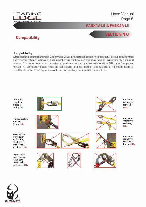
Compatibility:When making connections with Checkmate SRLs, eliminate all possibility of roll-out. Roll-out occurs when interference between a hook and the attachment point causes the hook gate to unintentionally open and release. All connections must be selected and deemed compatible with Xcalibre SRL by a Competent Person. All connector gates must be self-closing and self-locking, and withstand minimum loads of 3,600lbs. See the following for examples of compatible/incompatible connection.

User ManualPage 7
FABX1A-LE & FABX2A-LE
Fall Clearance*Eliminate Swing Fall whenever possible! If swing fall exists, always account for additional fall clearance.
Fall ClearanceSECTION 5.0

User ManualPage 8
FABX1A-LE & FABX2A-LE
Issue, Inspection, Storage & Rescue Planning
SECTION 6.0
Issue:This and associated equipment must be visually inspected by a competent person when initially delivered to site, thereafter the product must be inspected before and after use. A record card is printed in this manual, and should be updated after each routine inspection. Follow the points laid down in the section headed “Inspection” without deviation.
The supervisor must ensure that the equipment is being used correctly by a trained and/or otherwise competent person who is aware of its safe use and inspection. Additionally the supervisor must ensure that there are suitable and accessible anchorages, as described in this manual, in the working environment to allow safe anchorage of the device.
Inspection:Inspect the SRL, lanyard, hook and anchorage for signs of wear, deformation, damage or corrosion.Wire Rope - Ensure that the wire rope is free from cuts, abrasion & kinks.Ensure hook swivels & gate opens and closes correctly.Ensure load indicator is not deployed (see right). If the red section is visible, the SRL MUST be removed from service immediately.Pull lanyard sharply to engage brakes and ensure the brakes lock before each and every use.Pull out lanyard to ensure that it pays out and recoils smoothly.All housing screws must be secure.Check the user instructions are clear & legible.To clean the housing a mild detergent can be used with warm or cold water. At least every 12 months, a Competent Person other than the user must inspect the SRL. Competent Person inspections MUST be recorded in inspection log in instruction manual. The Competent Person must sign their initials in the box corresponding to the month and year the inspection took place.If for any reason the inspection of this SRL shows signs for concern or doubt then the SRL-LE must be quarantined and removed from service immediately. Advice should be sought from the supervisor and if still concerned the SRL must be sent to the supplier, an approved service agent or the manufacturer for service and re-calibration.
StorageStorage in a central protected location allows assurance of inspection on issue and return.The device should be stored in a clean dry place where it can be protected from damage by chemical attack and sharp objects . It should be stored with its instructions and record card at all times. Return the device back to it’s original box or other suitable container for storage & transportation. After use return to the store, never leave the device lying around site.
Rescue Planning:Before use, and when using the Checkmate SRL’s, users and supervisors should always make suitable provisions for rescue. A full risk assessment should be carried out to determine the most effective, safe and quickest form of rescue. For more information on specialist rescue systems or training please contact Checkmate.
This device may be serviced by the manufacturer or a manufacturer-authorized agent only. Never attempt to service or tamper with this unit in any way.
Red Deployment Indicator

User ManualPage 9
FABX1A-LE & FABX2A-LE
DIMSIN mm
CHECKMATE
127
48
WEIGHT: g
SURFACE AREA:mm2 DATE
DATE
APPD
DRAWN SCALE
CHKD
ISSPART NO.
USED ON
NO. OFF PARTS/ASSY
LINEAR ±0.1ANGULAR ±0°30'
MANUFACTURING TOLERANCESUNLESS OTHERWISE SPECIFIED
FINISH:
MATERIAL:
TITLE: DWG NO.SHEET1 OF 1PPELAB-367 FABX1LE ANSI LABEL
This
doc
umen
t is
give
n in
con
fiden
ce &
may
not
be
used
for a
ny p
urpo
se o
ther
than
that
for w
hich
it is
sup
plie
d n
or s
hall
any
part
of it
be
repr
oduc
ed o
r cop
ied
with
out t
he p
rior w
ritte
n co
nsen
t of "
Che
ckm
ate
Lifti
ng &
Saf
ety
LTD
."
DWG NO.
©
DO NOT SCALE THIS DRAWING COMPLIES WITH BS.8888 A4
All Intellectual Property, including drawings, branding, logo's and patents are owned by Checkmate Limited.
28/03/2013
NOTE: REMOVE ALL BURRS AND SHARP EDGES WITH 0.25MM MAX RAD OR CHAMFER
BN 1:1
2
[email protected]+44(0) 1795 668 280+44(0) 1795 580 333
New Road, Sheerness, Kent, England ME12 1PZ, UK
www.checkmateuk.comLET'S INNOVATE
CHECKMATE LIFTING & SAFETY LTD
LIFTING & SAFETY
DATE
Background Colour Grey
Text ColourBlack
Label Size127mmx48mm
PPELAB-85
N/A
N/A
N/A
BackgroundC: 0%M: 0%Y: 0%K: 33%
FABX1-LE Self-Retracting LifelinePart # 32100SPECIFICATIONS: Lifeline: 30’ x 3/16” Galvanized Steel(LE Use): Capacity range: 130 - 310 lbs.; Min. setback distance from edge: 8’; Max. arresting distance: 48” - 96’’; Max. free fall: 5’; Min. Fall clearance: 16.5‘ (Non-LE Use): Capacity range: 130 - 310 lbs.;Max. arresting distance: 54”; Free fall: not permitted; Fall clearance: 9’; Average arresting force: 900 lbs. Class B SRL
WARNING: Prior to use, fully read and understand all manufacturer’s instructions provided with equipment
at time of shipment.
USE: This device is only for use by one person as a fall arrester. Only make connections directly to attachment point on safety harness. Guard against swing-fall by k e e p i n g l i f e l i n e v e r t i c a l l y o v e r h e a d . E n s u r e t h a t connection to anchorage is secured properly before use. Avoid lifeline contact with sharp or abrasive edges and surfaces. May be used as a component of a PFAS in HLL applications. Design, installation, and utilization of HLLs must be supervised by a Qualified Person. Suitable for horizontal use. Competent Person must calculate fall clearance prior to use; fall clearance calculations must include considerations for swing fall. Clearance numbers specified based on lifeline installed vertically overhead and in-line with worker.
INSPECTION: Pr ior t o eac h use, inspect device per instructions, including locking function (sharp pull to test), retraction function, legibility of labels, evidence of defects, damage, or missing par ts, and condition of connectors, housing, fasteners, and lifeline (inspect full length). Inspection by Competent Person required at least ever y 12 months. Immediately remove from ser vice if evidence of shock pack deployment is found.
STANDARDS: ANSI Z359.14-14 & ANSI A10.32-12,OSHA 1926 Subpart M & OSHA 1910
Designed in the UK, assembled in America. US Patent No. 8,991,556 European Patent No. 2185247 & 2495017
91051 (Rev. A)
Lot #
Labels SECTION 7.0
CHECKMATE All Intellectual Property, including drawings, branding, logo's and patents are owned by Checkmate Limited.
1:1
[email protected]+44(0) 1795 668 280+44(0) 1795 580 333
New Road, Sheerness, Kent, England ME12 1PZ, UK
www.checkmateuk.comLET'S INNOVATE
CHECKMATE LIFTING & SAFETY LTD
LIFTING & SAFETY
1
N/A
PPELAB-368
30/07/15
BackgroundGrey
Text ColourBlack
Label SizeHeight - 155mmWidth - 55mm
N/A
N/A
AC
3FABX2-LE (ANSI)
CS 30/07/15
DB P
PPELAB-368
BackgroundC: 0%M: 0%Y: 0%K: 33%
FABX2-LE Self-Retracting LifelinePart # 32101
SPECIFICATIONS: Lifeline: 50’ x 3/16” Galv. Steel (LE Use): Capacity range: 130 - 310 lbs.; Min. setback distance from edge: 8’; Max. arresting distance: 48” - 96’’; Max. free fall: 5’; Min. Fall clearance: 16.5‘ (Non-LE Use): Capacity range: 130 - 310 lbs.;Max. arresting distance: 54”; Free fall: not permitted; Fall clearance: 9’; Average arresting force: 900 lbs. Class B SRL
WARNING: Prior to use, fully read and understand all manufacturer’s instructions provided with
equipment at time of shipment.
USE: This device is only for use by one person as a fall a r r e s t e r . O n l y m a k e c o n n e c t i o n s d i r e c t l y t o attachment point on safety harness. Guard against swing-fall by keeping lifeline ver tically overhead. Ensure that connection to anchorage is secured properly before use. Avoid lifeline contact with sharp or abrasive edges and sur faces. May be used as a component of a PFAS in HLL applications. Design, i n s t a l l a t i o n , a n d u t i l i z a t i o n o f H L L s m u s t b e super v ised by a Qual i f ied Per son. Sui t able f or horizontal use. Competent Person must calculate fall clearance prior to use; fall clearance calculations must include considerations for swing fall. Clearance n u m b e r s s p e c i f i e d b a s e d o n l i f e l i n e i n s t a l l e d vertically overhead and in-line with worker.
INSPECTION: Prior to each use, inspect device per instructions, including locking function (sharp pull to test), retraction function, legibility of labels, evidence of defects, damage, or missing parts, and condition of connector s, housing, fastener s, and l i fel ine (inspect full length). Inspection by Competent Person required at least ever y 12 months. Immediately r e m o v e f r o m s e r v i c e i f e v i d e n c e o f s h o c k p a c k deployment is found.
STANDARDS: ANSI Z359.14-14 & ANSI A10.32-12,OSHA 1926 Subpart M & OSHA 1910
Designed in the UK, assembled in America. US Patent No. 8,991,556 European Patent No. 2185247 & 2495017
91057 (Rev. A)
Lot #
DIMSIN mm
CHECKMATE
127
48
WEIGHT: g
SURFACE AREA:mm2 DATE
DATE
APPD
DRAWN SCALE
CHKD
ISSPART NO.
USED ON
NO. OFF PARTS/ASSY
LINEAR ±0.1ANGULAR ±0°30'
MANUFACTURING TOLERANCESUNLESS OTHERWISE SPECIFIED
FINISH:
MATERIAL:
TITLE: DWG NO.SHEET1 OF 1PPELAB-367 FABX1LE ANSI LABEL
This
doc
umen
t is
give
n in
con
fiden
ce &
may
not
be
used
for a
ny p
urpo
se o
ther
than
that
for w
hich
it is
sup
plie
d n
or s
hall
any
part
of it
be
repr
oduc
ed o
r cop
ied
with
out t
he p
rior w
ritte
n co
nsen
t of "
Che
ckm
ate
Lifti
ng &
Saf
ety
LTD
."
DWG NO.
©
DO NOT SCALE THIS DRAWING COMPLIES WITH BS.8888 A4
All Intellectual Property, including drawings, branding, logo's and patents are owned by Checkmate Limited.
28/03/2013
NOTE: REMOVE ALL BURRS AND SHARP EDGES WITH 0.25MM MAX RAD OR CHAMFER
BN 1:1
2
[email protected]+44(0) 1795 668 280+44(0) 1795 580 333
New Road, Sheerness, Kent, England ME12 1PZ, UK
www.checkmateuk.comLET'S INNOVATE
CHECKMATE LIFTING & SAFETY LTD
LIFTING & SAFETY
DATE
Background Colour Grey
Text ColourBlack
Label Size127mmx48mm
PPELAB-85
N/A
N/A
N/A
BackgroundC: 0%M: 0%Y: 0%K: 33%
FABX1-LE Self-Retracting LifelinePart #SPECIFICATIONS: Lifeline:(LE Use): Capacity range: 130 - 310 lbs.; Min. setback distance from edge: 8’; Max. arresting distance: 48” - 96’’; Max. free fall: 5’; Min. Fall clearance: 16.5‘ (Non-LE Use): Capacity range: 130 - 310 lbs.;Max. arresting distance: 54”; Free fall: not permitted; Fall clearance: 9’; Average arresting force: 900 lbs. Class B SRL
WARNING: Prior to use, fully read and understand all manufacturer’s instructions provided with equipment
at time of shipment.
USE: This device is only for use by one person as a fall arrester. Only make connections directly to attachment point on safety harness. Guard against swing-fall by k e e p i n g l i f e l i n e v e r t i c a l l y o v e r h e a d . E n s u r e t h a t connection to anchorage is secured properly before use. Avoid lifeline contact with sharp or abrasive edges and surfaces. May be used as a component of a PFAS in HLL applications. Design, installation, and utilization of HLLs must be supervised by a Qualified Person. Suitable for horizontal use. Competent Person must calculate fall clearance prior to use; fall clearance calculations must include considerations for swing fall. Clearance numbers specified based on lifeline installed vertically overhead and in-line with worker.
INSPECTION: Pr ior t o eac h use, inspect device per instructions, including locking function (sharp pull to test), retraction function, legibility of labels, evidence of defects, damage, or missing par ts, and condition of connectors, housing, fasteners, and lifeline (inspect full length). Inspection by Competent Person required at least ever y 12 months. Immediately remove from ser vice if evidence of shock pack deployment is found.
STANDARDS: ANSI Z359.14-14 & ANSI A10.32-12,OSHA 1926 Subpart M & OSHA 1910
Designed in the UK, assembled in America. US Patent No. 8,991,556 European Patent No. 2185247 & 2495017
91091 (Rev. A)
Lot #
CHECKMATE All Intellectual Property, including drawings, branding, logo's and patents are owned by Checkmate Limited.
1:1
[email protected]+44(0) 1795 668 280+44(0) 1795 580 333
New Road, Sheerness, Kent, England ME12 1PZ, UK
www.checkmateuk.comLET'S INNOVATE
CHECKMATE LIFTING & SAFETY LTD
LIFTING & SAFETY
1
N/A
PPELAB-368
30/07/15
BackgroundGrey
Text ColourBlack
Label SizeHeight - 155mmWidth - 55mm
N/A
N/A
AC
3FABX2-LE (ANSI)
CS 30/07/15
DB P
PPELAB-368
BackgroundC: 0%M: 0%Y: 0%K: 33%
FABX2-LE Self-Retracting LifelinePart #
SPECIFICATIONS: Lifeline:(LE Use): Capacity range: 130 - 310 lbs.; Min. setback distance from edge: 8’; Max. arresting distance: 48” - 96’’; Max. free fall: 5’; Min. Fall clearance: 16.5‘ (Non-LE Use): Capacity range: 130 - 310 lbs.;Max. arresting distance: 54”; Free fall: not permitted; Fall clearance: 9’; Average arresting force: 900 lbs. Class B SRL
WARNING: Prior to use, fully read and understand all manufacturer’s instructions provided with
equipment at time of shipment.
USE: This device is only for use by one person as a fall a r r e s t e r . O n l y m a k e c o n n e c t i o n s d i r e c t l y t o attachment point on safety harness. Guard against swing-fall by keeping lifeline ver tically overhead. Ensure that connection to anchorage is secured properly before use. Avoid lifeline contact with sharp or abrasive edges and sur faces. May be used as a component of a PFAS in HLL applications. Design, i n s t a l l a t i o n , a n d u t i l i z a t i o n o f H L L s m u s t b e super v ised by a Qual i f ied Per son. Sui t able f or horizontal use. Competent Person must calculate fall clearance prior to use; fall clearance calculations must include considerations for swing fall. Clearance n u m b e r s s p e c i f i e d b a s e d o n l i f e l i n e i n s t a l l e d vertically overhead and in-line with worker.
INSPECTION: Prior to each use, inspect device per instructions, including locking function (sharp pull to test), retraction function, legibility of labels, evidence of defects, damage, or missing parts, and condition of connector s, housing, fastener s, and l i fel ine (inspect full length). Inspection by Competent Person required at least ever y 12 months. Immediately r e m o v e f r o m s e r v i c e i f e v i d e n c e o f s h o c k p a c k deployment is found.
STANDARDS: ANSI Z359.14-14 & ANSI A10.32-12,OSHA 1926 Subpart M & OSHA 1910
Designed in the UK, assembled in America. US Patent No. 8,991,556 European Patent No. 2185247 & 2495017
91093 (Rev. A)
Lot #

User ManualPage 10
FABX1A-LE & FABX2A-LE
Quality, Legislation & ExclusionsSECTION 8.0
4.1 QualityAll Checkmate products are manufactured under ISO 9001 and to the highest standards. The scope of use within the certification held allows Checkmate to design, manufacture and test Personal Protection Equipment.Horizontal tensile test machine, abrasion tester and dynamic drop test rig are just part of the full range of test facilities used to ensure ultimate safety of our product range.All Checkmate devices must only be installed by Checkmate personnel or a trained operator. Strict training is given and written exams are completed before full certification can be given to operators.
4.2 Legislation and StandardsThe FABX1A-LE & FABX2A-LE have been designed to meet the requirements of ANSI Z359.14:2014, OSHA 1910 & OSHA 1926 subpart M.For clarification on any certification issues contact Checkmate.
4.3 ExclusionsCheckmate holds global product liability cover for your safety.Checkmate will NOT however be responsible for:a. Users who are out of the scope
of any written manuals of training given.
b. Any device that has NOT been inspected under the current legislation and manufacturers guidelines.
c. Devices that have been damaged.d. When the maximum weight in Kg
has been exceeded.e. Devices that have NO serial number
markings, and the manufacturers name, Checkmate Lifting & Safety LTD, is not present.

User ManualPage 11
FABX1A-LE & FABX2A-LE
Section 9.0DATE:
USER:
Record CardSERIAL NO:
PRODUCT CODE:
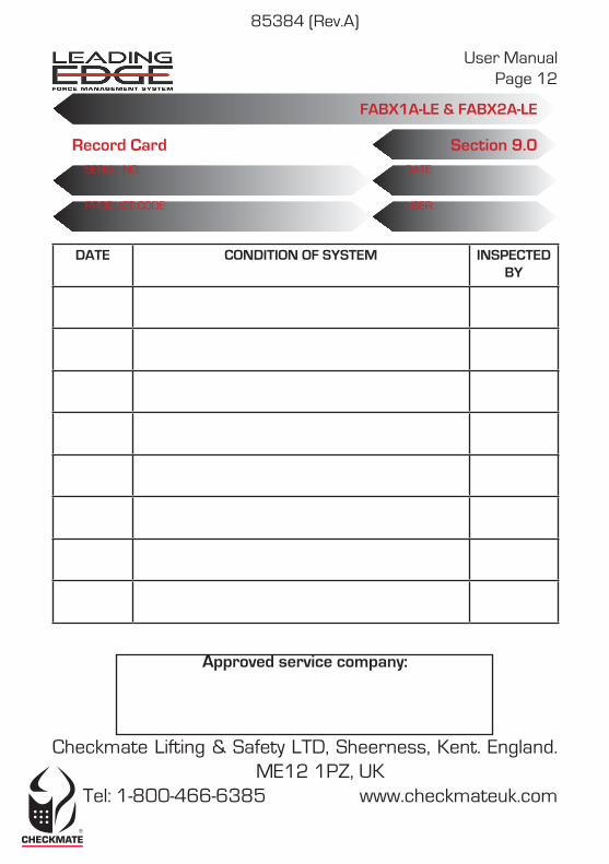
DATE CONDITION OF SYSTEM INSPECTED BY
User ManualPage 12
FABX1A-LE & FABX2A-LE
Approved service company:
Checkmate Lifting & Safety LTD, Sheerness, Kent. England. ME12 1PZ, UK
Tel: 1-800-466-6385 www.checkmateuk.com
Section 9.0DATE:
USER:
Record CardSERIAL NO:
PRODUCT CODE:
DATE CONDITION OF SYSTEM INSPECTED BY
85384 (Rev.A)