FABRICATION TECHNOLOGY - NASA Utilization Office National Aeronautics and Space Administration...
25
NASA SP-5978 (02) September 1974 FABRICATION TECHNOLOGY (NASA-SP-5978 (02)) FABRICATION N75-12162 TECHNOLOGY: A COMPILATION Technology Utilization (NASA) 25 p HC $1.00 CSCL 13H Unclas __ ___ __ G/31 03702 A COMPILATION NA *TI * R 'O IS DSARE AMINISTR ATI https://ntrs.nasa.gov/search.jsp?R=19750004090 2018-05-21T15:24:34+00:00Z
Transcript of FABRICATION TECHNOLOGY - NASA Utilization Office National Aeronautics and Space Administration...

NASA SP-5978 (02)September 1974
FABRICATION TECHNOLOGY
(NASA-SP-5978 (02)) FABRICATION N75-12162TECHNOLOGY: A COMPILATION TechnologyUtilization (NASA) 25 p HC $1.00
CSCL 13H Unclas__ ___ __ G/31 03702
A COMPILATION
NA *TI * R 'O IS DSARE AMINISTR ATI
https://ntrs.nasa.gov/search.jsp?R=19750004090 2018-05-21T15:24:34+00:00Z

Foreword
The National Aeronautics and Space Administration has established a TechnologyUtilization Program for the dissemination of information on technological developmentswhich have potential utility outside the aerospace community. By encouraging multipleapplication of the results of its research and development, NASA earns for the public anincreased return on the investment in aerospace research and development programs.
This document is one in a series intended to furnish such technological information.Divided into four sections, the Compilation presents a number of devices and techniquesthat may be of interest to production engineers and shop workers in both small andlarge organizations. The sections include articles on cutting, shaping, and forming;working with metals; and coatings.
Additional technical information on the articles in this Compilation can berequested by circling the appropriate number on the Reader Service Card includedin this Compilation.
The latest patent information available at the final preparation of this Compilationis presented on the page following the last article in the text. For those innovations onwhich NASA has decided not to apply for a patent, a Patent Statement is not included.Potential users of items described herein should consult the cognizant organization forupdated patent information at that time.
We appreciate comment by readers and welcome hearing about the relevance andutility of the information in this Compilation.
Jeffrey T. Hamilton, DirectorTechnology Utilization OfficeNational Aeronautics and Space Administration
NOTICE This document was prepared under the sponsorship of the National Aeronautics and SpaceAdministration. Neither the United States Government nor any person acting on behalf of the UnitedStates Government assumes any liability resulting from the use of the information contained in thisdocument, or warrants that such use will be free from privately owned rights.
For sale by the National Technical Information Service, Springfield, Virginia 22151. $1.00

Contents
Page
SECTION 1. CUTTING, SHAPING, AND FORMING
One-Step Explosive Forming of Metal: A Process Improvement ......... 1
Grinding-Wheel Dresser .......................................... 2
Break-Formed Structural Panels ............................... 4
Contour Polishing Glancing-Incidence Optics ..................... 5
Zonal Contouring Using a "Dentist's-Drill" Polisher ................. 6
Stepover Chart for Ramping Cuts ............................. 7
Fabrication of Irregular Surface Shapes ................... ...... 8
SECTION 2. METAL FABRICATION TECHNIQUES
Metallic Masking for Electroplating ............................. 9
Protection From Hydrogen-Environment Embrittlement ............... 9
Specially-Treated Stainless-Steel Screws for
High-Temperature Use in a Vacuum ......................... 10
Method of Rapidly Aging an Electrolyte ......................... 11
Technique for Visual Inspection of Nickel-Plating Quality ............. 11
New Process for Welding Bare-Junction Thermocouples to
Refractory Metals ...................................... 12
Electrodeposited Copper for High-Temperature Use ................. 13
Electron-Beam Welding of Dissimilar Metals ................... .... 14
SECTION 3. COATINGS AND COATING TECHNIQUES
Reducing Sticking of Reacting Pack Material in a
Pack Coating Process ................................... 14
High-Reliability, Elastomer-Seal Installation ....................... 15
Adapter and Disposable Bag for Spray Guns ....................... 16
A New Potting, Sealing, and Conformal Coating System ............. 17
Application of a Soft-Anodizing Process for Optical Instruments ......... 17
SECTION 4. MISCELLANEOUS FABRICATION TECHNIQUES
Glass Capillary Tube Cutter and Sealer ........................... 18
Reduction of Stiffness Requirements for Flat Frames ................. 19
Low-Resistance Contacts for Solar Cells ......................... 20
A Technique for Adding Solder Bumps to Integrated Circuit Chips ....... 21
Graphs of Stress and Tension Properties of Bolts ................... 21
PATENT INFORMATION ..................................... 22
ii

Section 1. Cutting, Shaping, and Forming
ONE-STEP EXPLOSIVE FORMING OF METAL:A PROCESS IMPROVEMENT
Charge Hold-DownRing
Shim
StainlessSteelBlank
Die
OP-Vacuum
0 2 Tank-Dome Fabrication Setup
Explosive forming is a process that uses the force of is used to position the explosive accurately. In addition,an explosive charge to shape a blank metal stock that shims are installed to prevent the ring from cocking andhas been placed in a die (see figure). It has been quite to improve the uniformity of the clamping surfacedifficult to control the dimensions of the formed parts. (see figure).For instance, domes formed by this method exhibit When used to form domes, these improvementsthinning and distortion. eliminate thinning and distortion. As a result, the
This poor dimensional control is attributed to an number of rejects in the process is markedly reduced.uneven local frictional force between the blank stockand the die. Two factors are important contributors to Source: J. F. Schuessler andthis disparity: (1) The flatness tolerances applied to the R. L. Rhoton offabrication of the hold-down rings are not stringent McDonnell Douglas Corp.enough; and (2) the explosive charge is placed in the under contract tovisually determined center of the blank, which in fact Marshall Space Flight Centermay not be the true center. (MFS-22585)
In an improved version of the process, the hold-downring is machined to a uniformly flat surface. Then, a jig Circle I on Reader Service Card.
I

2 FABRICATION TECHNOLOGY
GRINDING-WHEEL DRESSER
A relatively inexpensive grinding-wheel dresser can This wheel dresser can form variously sized radii onmaintain a very precise radius on the grinding wheel. the grinding wheel. It is rigidly clamped to the crossIn precision work, the radius of the wheel must be slide of the lathe. The grinding head is attached to thedressed after each cut, without changing the wheel-to-lap compound slide of the lathe, allowing the wheel to bedistance along either the X or Y axis. fed into the dresser by turning the handle on the
Commercially available wheel dressers require con- compound shield (Figure 1). In this way, the cuttingsiderable set-up time after each cut. They will not swing edge of the wheel is in exactly the same position on theout of the way to allow a cut to be made unless thedresser is removed from the lathe.
Figure 1. Aligning Wheel With Dresser

CUTTING, SHAPING, AND FORMING .3
Figure 2. Dresser Swings Out of the Way
X and Y axes after dressing. No compensation is required ment, and would be very helpful in small shops that dofor the material removed from the grinding wheel not have expensive grinding equipment.during the dressing. Afterwards, the dresser will swingbehind the cutting edge of the wheel, where it will not Source: Edgar Kauffman, Robert Hessler,interfere with the cut (Figure 2). and Dott Wells
This dresser is now being used during the fabrication Goddard Space Flight Centerof aspheric laps for grazing-incidence optics. It could be (GSC-1 1140)used with any lathe having a tool-post grinding attach-
No further documentation is available.

4 FABRICATION TECHNOLOGY
BREAK-FORMED STRUCTURAL PANELS
Cross Sections for Break-Formed Panels
Several methods are used to form structural panels. The panels are made by three separate formingStretch-formed panels and corrugated panels with circu- processes to produce panels of the lightest weight.lar-arc cross sections -are common. However, these (Examples of a few possible cross sections are shown inmethods do not offer the versatility or proper end the figure.) The sheet material is first formed into full-closings for complex structures. The use of break- length uniform corrugations of the desired cross sectionforming fabrication techniques produces a structure of by break-forming. Break-forming bends but does notlighter weight and offers improved economy, reliability, stretch or thin the material. This approach is versatileand versatility when compared to current methods. and controls the cross section geometry.
This technique should be of particular interest to the In the second step, matched dies are used to reformbuilding trades and to railroad-car construction firms. the ends of the panels, increasing the width of the flatsIndeed, corrugated panels have been used in these areas between the end closures. The last step is high-for many years, but they had not been developed energy-rate forming, such as electrohydraulic forming,sufficiently to be of use in aerospace construction. The to produce the final shape of the end closures. Inaerospace industry has profited from this commercial electrohydraulic forming, an electrical discharge melts aexperience and is able to return, to the private sector, wire inside a water-filled chamber to effect high energy-the dividend of a new, more economical, and versatile impulse formation of the part using only a female die;process. the material is stretched and bent very little. The
These panels are designed for combined loads, which overall process affords maximum versatility and controlinclude edge compression, inplane shear, and bending and requires only a minimum of final handwork.due to lateral pressure. One of the key features of theadvanced structural panel is the end closure, which Source: Max D. Musgrove offorms the transition from the uniform-beaded or tubular The Boeing Companysection to the flat required for attachment at the end of under contract tothe panel. The panel must be formed from thin sheet Langley Research Centerwithout compromising either the efficiency available in (LAR-1 1171)the uniform section or the integrity of the end enclosure.
Circle 2 on Reader Service Card.

CUTTING, SHAPING, AND FORMING
CONTOUR POLISHING GLANCING-INCIDENCE OPTICS
Sponge Rubber.Surface
ComponentBeingPolished
Polisher for Glancing-Incidence Optics
Using the contour polisher shown in the figure, The pitch used here should be more viscous than thatglancing-incidence optical aspherics may be contoured normally used for polishing. In conventional polishing,to within V 10 rms. The process is simple and rapid. 60 to 80 percent of the area being polished is in contact
The polisher is placed on top of the aspherical optical with the polisher. Here only 10 percent is. The result iselement. The element rotates about its axis at 40 rpm. increased slurry evaporation and the associated heat loss.At the same time, the polisher oscillates perpendicular A 1:3 ratio, by weight, of 1800 and 1940 F (820 andto the rotation. The ratio of the oscillation to the length 900 C) melting-point coal tars has proven effective forof the blank is 1:6.4, and the rate of oscillation is this technique.150 cycles/minute. A weight of 0.35 lb per in.2 The aspherics is contoured by shaving away small(25g per cm 2 ) of pitch surface is applied to the polisher. amounts of pitch that correspond to "low" zones. The
The base of the polisher is a rectangular metal plate, method has produced surfaces of better than /10 rmsthe same length as the optical component. The width (:5460A) that are free of scratches and "sleets".of the plate is between one fourth and one third themedian diameter of the component. One surface of the Source: Charles Fleetwood, Jr.base is curved to match the aspheric. On this surface, Goddard Space Flight Center0.12 in. (3 mm) of sponge rubber are bonded with red (GSC-1 1781)sealing wax. The rubber is shellacked and dried; then0.08 in. (2 mm) of pitch are applied. The shellac No further documentation is available.provides improved adherance.

6 FABRICATION TECHNOLOGY
ZONAL CONTOURING USING A "DENTIST'S-DRILL" POLISHER
A polishing tool, similar to a dentist's drill, can be with red sealing wax. Most types of wool felt can beused to polish away fabrication errors on glancing- used, and any optical-grade pitch of medium hardness isincidence aspherical optical components. Glancing-inci- satisfactory.dence aspherics require fabrication techniques differing The pitch-impregnated felt polisher will withstandfrom the well-known methods for the normal-incidence greater pressures than a polisher using only pitch. It willaspherics used with most of today's telescopes. This last longer, and the greater pressure saves tirrie bypolishing tool reduces the cost and time in optically increasing the rate of material removal.contouring glancing-incidence optical components of When shaping it, the optical component is rotated atring, donut, or solid shapes. around 48 rpm. The disk polisher rotates at nearly
The drill is similar to that used by a dentist. But the 1300 rpm. A weight of from 281 to 1,400 g/cm 2
drill bit is replaced with a 13-mm (0.5-in.) diameter (4 to 20 psi) is applied. The felt is centered over thecurved- disk (see figure). The curvature of the disk is error zone, and a slight traverse motion is applied. Anymatched to the median curvature of the aspheric. A suitable polishing agent such as water and cerium oxidepitch-impregnated piece of felt is attached to the disk may be used.
Zonal Contouring TechniqueDisk Posher
Glancing-incidenceOptical Component
"Dentist's Drill" Bit
Zonal Contouring Technique

CUTTING, SHAPING, AND FORMING 7
rhis polisher has been used to finish the optics for Source: Charles Fleetwood, Jr. andglancing-incidence extreme-ultraviolet telescopes at the Charles DavisGoddard Space Flight Center. It should also be useful Goddard Space Flight Centerwith other glancing-incidence optical systems, and possi- (GSC-I 1780)bly with X-ray telescopes and normal-incidence optics.
No further documentation is available.
STEPOVER CHART FOR RAMPING CUTS
FILLETDIAMETER RADIUS 5
° 10* 15* 20* 25' 30* 35' 40* 45' 50' 55" 60' 65" 70' 75' 80* 85*
.250 0 .172 .126 .103 .089 .079 .071 .065 .059 .054 .050 .046 .041 .037 .033 .028 .023 .016.060 .121 .095 .081 .073 .067 .062 .058 .054 .050 .047 .044 .040 .036 .033 .028 .022 .016.090 .024 .076 .068 .064 .060 .057 .054 .051 .048 .045 .043 039 036 .032 .028 .022 .016
.375 0 .216 .156 .128 .110 .097 .088 .080 .073 .067 .061 .056 .051 .046 .040 .035 .028 .020.060 .178 .132 .110 .097 .088 .080 .074 .069 .064 .059 .054 .049 .045 .040 .034 .027 .020.090 156 .119 .101 .090 083 .076 .071 .066 .062 .057 .054 .049 .045 .040 .034 .027 .020.120 .129 .104 .090 .083 .077 .072 .068 .064 .060 .056 .053 .048 .044 .040 .034 .027 .020
.500 0 .253 .181 .148 .127 .113 .101 .092 .084 .077 .070 .065 .059 .053 .047 .040 .033 .023.060 .220 .162 .133 .117 .104 .095 .087 .080 .074 .069 .063 .057 .052 .046 .040 .032 .023.090 .203 .151 .125 .111 .100 .092 .085 .079 .073 .067 .063 .057 .052 .046 .040 .032 .023.120 .184 .139 .117 .105 .096 .088 .082 .077 .072 .066 .062 .056 .052 .046 .040 .031 .023
.750 0 .313 .223 .182 .156 .138 .124 .113 .103 .095 .087 .079 .072 .065 .057 .049 .040 .028.060 .288 .205 .169 .148 .132 .119 .109 .100 .092 .085 .078 .071 .064 .057 .049 .039 .028.090 .275 .199 .163 .143 .128 .117 .107 .099 .091 .084 .076 .070 .064 .057 .049 .039 .028.120 .261 .191 .157 .139 .125 .114 .105 .097 .090 .083 .076 .070 .064 .057 .049 .039 .028
1.000 0 .363 .259 .210 .181 .160 .144 .131 .120 .109 .100 .092 .083 .075 .066 .057 .046 .032.060 .343 .245 .199 .173 .154 .139 .127 .117 .107 .098 .091 .082 .074 .066 .056 .045 .032.090 .332 .238 .194 .169 .151 .137 .125 .115 .106 .098 .090 .081 .074 .066 .056 .045 .032.120 .320 .231 .189 .166 .148 .135 .124 .114 .105 .097 .089 .081 .074 .066 .056 .045 .032.180 .296 .216 .178 .158 .142 .130 .120 .111 .103 .096 .088 .080 .073 .066 .056 .045 .032.250 .264 .197 .165 .148 .135 .124 .116 .108 .101 .094 .087 .080 .073 .065 .056 .045 .032
1.250 0 .408 .289 .235 .202 .179 .161 .146 .134 .122 .112 .102 .093 .084 .074 .063 .051 .036.060 .389 .278 .225 .196 .174 .157 .143 .131 .121 .110 .101 .092 .083 .074 .063 .050 .036.090 .380 .272 .220 .192 .171 .155 .142 .130 .120 110 .101 .091 .083 .074 .063 .050 .036.120 .370 .265 .216 .189 .169 .153 .140 .129 .119 .109 .100 .091 .083 .073 .063 .505 .036.180 .349 .252 207 .182 .163 .149 .137 .126 .117 .108 .100 .091 .082 .073 .063 .050 .036.250 .323 .236 .195 .173 .157 .144 .133 .124 .115 .106 .099 .091 .082 .073 .063 .050 .036
1.500 0 .448 .318 .258 .222 .196 .176 .160 .146 .134 .123 .112 .102 .097 .081 .069 .056 .040.060 .431 .307 .248 .216 .191 .173 .157 .144 .132 .121 .111 .100 .091 .081 .069 .055 .039.090 422 .301 .244 .213 .189 .171 .156 .143 .132 .121 .111 .100 .091 .081 .069 .055 .039.120 .414 .296 .240 .210 .187 .169 .155 .142 .131 .120 .110 .100 .091 .081 .069 .055 .039.180 .395 .284 .232 .203 .182 .165 .152 .140 .129 .119 .110 .099 .091 .081 .069 .055 .039.250 .372 .270 .222 .196 .176 .161 .148 .137 .127 .117 .109 .099 .090 .080 .069 .055 .039
2.000 0 .519 .367 .298 .256 .226 .204 .185 .169 .155 .142 .130 .118 .106 .093 .080 .065 .046.060 .505 .358 .289 .251 .223 .201 .183 .167 .153 .140 .129 .116 .105 .093 .080 .063 .046.090 .497 .353 .286 .249 .221 .199 .181 .166 .153 .140 .129 .116 .105 .093 .080 .063 .046.120 .489 .348 .282 .246 .218 .197 .180 .165 .152 .139 .128 .116 .105 .093 .080 .063 .046.180 .474 .339 .275 .240 .214 .194 .178 .163 .150 .138 .127 .115 .105 .093 .080 .063 .046.250 .455 .327 .267 .234 .209 .190 .175 .161 .149 .137 .126 .115 .105 .093 .080 .063 .046
When tapered sections are required, the flow of Source: W. R. Vaughn ofoperations has to be suspended while the machinist Rockwell International Corp.calculates the ramping cut needed and programs the under contract tocutting tools accordingly. To save time in these opera- Johnson Space Centertions, a chart was devised to provide a ready reference (MSC-17288)of stepover values -for scallop heights. The diameterof the cutter and its fillet radius are taken into account; No further documentation is available.and the machinist is able to read off the adjustmentnecessary, for cutting up or down on any angle,without resorting to calculations. This enables the cutterto be set without delay.

8 FABRICATION TECHNOLOGY
FABRICATION OF IRREGULAR SURFACE SHAPES
General Mechanical-Design Approach to the Construction of an Ellipsoidal Reflector.Surface of Ellipse is Developed From Closely-Spaced Parallel Rods Which ArePositioned by Threading Through Holes Accurately Located in Flat Sheets WhichAre, in Turn, Attached to a Rigid Flat Reference Plane.
A new technique has been developed for forming Thin round rods are threaded through the holes tostructures with precise but irregular shapes. The tech- form the desired surface. After the rods are in place, thenique is relatively inexpensive and adaptable to mass excess portion of the flat plates may be cut away. Theproduction. It was conceived originally for the fabrica- accuracy of the construction is assured through thetion of elliptical microwave reflectors, but may be positioning of the holes, and further precision fixtureuseful in constructing bridges and buildings and as a or measuring systems are not required.reinforcement method for curved concrete structures.
The general technique is illustrated in the figure. A Source: W. C. Brown oflarge number of holes are drilled or punched in flat Raytheon Companyplates that are then mounted on a flat supporting under contract toframe. The positions of the holes are chosen according Marshall Space Flight Centerto the final shape desired. For mass production, the (MFS-22205)process can be computerized.
Circle 3 on Reader Service Card.

9
Section 2. Metal Fabrication Techniques
METALLIC MASKING FOR ELECTROPLATING
Metallic masking can eliminate unwanted chemical break down, the copper will act as a second line ofattack on the basis metal during electroplating. Experi- defense and protect the aluminum from attack by theence at the Goddard Space Flight Center's Engineering gold-plating solution.Services Division has shown that a copper mask prevents After the piece is electroplated and the lacquer oraluminum from being accidentally attacked by a gold tape is taken off, the exposed copper can be removedplating solution during selective electroplating. chemically with nitric acid. This will not harm the gold
Conventional maskants such as lacquer or electro- or the aluminum.plater's tape frequently break down. Lacquer coats may This method has been used successfully to electro-be somewhat porous, allowing the plating solution to plate a gold band 0.051 cm (0.02 in.) thick andpenetrate to the metal. Electroplater's tape frequently 1.270 cm (0.5 in.) wide, to be used as a radiation shieldlifts at the edges during processing. on the inside of an aluminum reticle holder.
These problems are solved when a metallic mask isused in conjunction with the tape or lacquer. For Source: Earl D. Ellisexample, a copper mask can be used when selectively Goddard Space Flight Centergold plating aluminum. The piece is prepared for plating, (GSC-11203)and a copper mask is electroplated over the entiresurface. Then, the area not to be gold plated is further No further documentation is available.masked with tape or lacquer. Should this outer mask
PROTECTION FROM HYDROGEN-ENVIRONMENT EMBRITTLEMENT
Alloys, such as Inconel, having high strength-to-weight screen, and the assembly is brazed at an appropriateratios become embrittled in a hydrogen environment. temperature. The wire screen holds the braze byThis embrittlement may be avoided by applying a capillary retention, insuring uniform coverage of thebraze-wash coating of a hydrogen-impermeable material part.such as copper. However, at the high temperatures usedfor brazing, the coating tends to liquify and run off, Source: D. I. MacFarlane ofleaving the part unevenly protected. Rockwell International Corp.
Excessive run-off may be prevented by covering the under contract topart with a fine-mesh stainless steel wire screen. The Marshall Space Flight Centerscreen is cut and contoured to fit the part. It is then (MFS-19172)attached by resistance spot welding. After spot welding,a braze-alloy powder and a flux are "painted" on the Circle 4 on Reader Service Card.

10 FABRICATION TECHNOLOGY
SPECIALLY-TREATED STAINLESS-STEEL SCREWS FORHIGH-TEMPERATURE USE IN A VACUUM
After lengthy exposure in a vacuum at temperaturesas high as 810 K (10000 F), stainless-steel screws aredifficult to remove. Screws used in holes tapped instainless steel, or with stainless-steel nuts, will gall,seize, and sometimes weld together. This is especiallytrue for screws with machine-cut threads. The spalling,or crazing, of the threaded surfaces (see Figure 1) con-tributes to the seizing. The jagged surface edges tend tointerlock with similar surfaces on nuts or tapped holes.
Seizing can be avoided by using oxidized stainless-steel screws, with rolled threads, coated with boronnitride powder. The boron nitride lubricant does notoutgas as do conventional lubricants such as molybdenumdisulfide. The smooth surface of the rolled threads(see Figure 2) helps to preclude binding and interlockingof the threaded surfaces.
The screws and nuts are prepared as follows:1. Degrease the parts.
Figure 2. Rolled Thread
2. Passivate the parts with a 20% (by volume) solutionof nitric acid, containing sodium dichromate (4ounces per gallon of solution). Allow 45 minutes forpassivation; then rinse three times with tap water:cold, hot, and a final cold rinse. Air-dry the parts.
3. Heat the parts in a furnace (atmospheric) at 1150 K(16000 F) for one hour. Remove the parts from thefurnace and air-cool them.
4. Clean the parts ultrasonically.5. Apply the boron nitride powder to the threads upon
assembly.This technique should be of interest throughout the
vacuum industry, particularly to research engineersworking with and developing hardware that is exposedto a high-temperature vacuum environment.
Source: Lawrence A. Mueller,Ernest A. Koutnik, and
Figure 1. Spalled Thread Vincent R. LalliLewis Research Center
(LEW-11176)
No further documentation is available.
METAL FABRICATION TECHNIQUES 11
METHOD OF RAPIDLY AGING AN ELECTROLYTE
The electrodeposition of nickel has required costly, 2. Aged nickel anode chips can be used with newtime-consuming preliminary operations. Furthermore, electrolytes, or conversely, an aged electrolyte canthe nickel plating frequently suffers from spotty adhesion be used with new anode chips. When used with theand marginal tensile properties. Two rapid methods of high current density, this technique can furtheraging nickel sulfamate electrolyte solution overcome reduce the required time by from 65 to 75 percent.these difficulties. Electrodeposition with the aged so-lution results in a heavy nickel coating with consistent Source: J. E. O'Tousa andoptimum mechanical properties. In addition, the process F. T. Schuler ofdoes not require the use of additives. Rockwell International Corp.
The two methods that may be used to speed the under contract toaging process are: Marshall Space Flight Center1. The anode current may be increased. A sevenfold (MFS-19178)
increase in current reduces the required time by afactor of 3.5 (from 700 to 200 ampere-hours per Circle 5 on Reader Service Card.gallon of electrolyte).
TECHNIQUE FOR VISUAL INSPECTION OF NICKEL-PLATING QUALITY
During the fabrication of platelet-based components Furthermore, the method simplifies cleaning and hand-(e.g., injectors or chambers) several thin nickel platelets ling, thus reducing quality-control costs and increasingare bonded by braze-alloy deposition. It is difficult reliability.to determine whether the nickel sheet has been nickelplated over the entire surface, since the nickel base and Source: J. Addoms, R. Boyce, andthe nickel plate are similar in appearance. K. Gustafson of
The plating may be. examined visually if the nickel Aerojet Liquid Rocket Co.base metal is colored. A thin flashing of electrolytic under contract tocopper, 2 to 8 micrometers thick, colors the base metal Marshall Space Flight Centerand allows areas of incomplete plating to be seen with (MFS-21151)the eye.
Bonds formed with this technique were subjected to No further documentation is available.metallographic analysis and found to be excellent.

12 FABRICATION TECHNOLOGY
NEW PROCESS FOR WELDING BARE-JUNCTION THERMOCOUPLESTO REFRACTORY METALS
A bare chromel/alumel thermocouple welded directly Step 3. The 0.024-in. (0.61-cm) diameter alumel wireto niobium 1% zirconium is unreliable due to crystal- of the thermocouple is laid across the Talization and embrittlenient of the juncture, caused by interface material and spot-welded at 25 to 35the high current load required to make the weld. In a watt-seconds of power (see Figure 2).new process, a bare-junction thermocouple is joined to arefractory metal with a weld of sufficient strength tohave a long effective life at high temperatures [17000 to2400 0 F (1200 to 1600 K)J. uWire
The new process makes use of an interface material Ta Spot[0.005-in. (0.0127-cm) Ta foil] that is welded easily torefractory metal and the thermocouple wire. The thermo-couple wire can be welded to the tantalum with an 80%to 90% lower power factor. This low-power spot weldeliminates the junction degradation that occurs whenwelding without the interface material. The steps in thisnew process are as follows:Step 1. The surface of the refractory metal is cleaned
with a clean smooth file. Clean degreased Figure 2. Step Threetantalum foil 0.005-in. (0.0127-cm) thick (min-imum) is spot welded to the refractory metal 4P Chromelat about 100 to 200 watt-seconds of power in Wireone spot of approximately 1/16-in. (0.015-cm)diameter.
Step 2. The foil is peeled back until the area spot-welded shears away from the parent foil. This Aluel Wireleaves a raised area of Ta approximately 1/16in. in diameter and 0.005 in. high on therefractory metal surface (see Figure 1).
Ta Foil
Spot
Figure 3. Step Four
Step 4. The chromel wire is laid across the alumel wire,over the weld at a 150 to 300 angle, and is spot-welded to the alumel wire to complete the
Refractory thermocouple junction. From 20 to 28 watt-Metal Base seconds are used to make a secure junction
(see Figure 3).Step 1. Steps One and Two

METAL FABRICATION TECHNIQUES 13
Note: For best results, all welds should be made with Source: Glenn M. Haskins ofan argon cover gas and with a tungsten elec- Caltech/JPLtrode. The positive terminal is connected to the under contract torefractory metal base, and the negative terminal NASA Pasadena Officeis connected to the tungsten electrode. (NPO-11435)
No further documentation is available.
ELECTRODEPOSITED COPPER FOR HIGH-TEMPERATURE USE
The ductility of electrodeposited copper at tempera- from 107 to 645 A/m' (10 to 60 A/ft2) for conven-tures above 533 K (5000 F) is considerably less than that tional processes. The electrolyte bath is continuouslyof wrought copper. For this reason, electrodeposited agitated and is kept at 303 to 306 K (850 to 900 F),copper has been restricted to comparatively low- which is slightly lower than for conventional processes.temperature uses. In addition to its increased ductility, copper electro-
In a new process employing modified parameters, deposited by this process possesses a much finer grainelectrodeposited copper is produced with an elongation structure. It can, therefore, be used where high tempera-of 20% at 644 K (7000 F), as compared with 5% for the tures and structural loading previously excluded the usestandard process. of electrodeposited copper.
The basic electrolyte in the new process consists ofreagent-grade copper sulfate (CuSO 2-5H 2 0) at a con- Source: F. T. Schuler andcentration of 21 to 24 g/l (28 to 32 oz/gal) and reagent- H. A. Tripp ofgrade sulfuric acid at 6 to 7.5 g/1 (8 to 10 oz/gal). In Rockwell International Corp.addition, the electrolyte contains 0.39 g/1 (1.5 g/gal) of under contract topentose. The anodes are chips of low-oxygen-content Marshall Space Flight Centercopper held in titanium baskets, with polypropylene (MFS-19173)bags as covers. A controlled current density of 215 A/m 2
(20 A/ft2 ) is used, as compared to current densities of Circle 6 on Reader Service Card.

14 FABRICATION TECHNOLOGY
ELECTRON-BEAM WELDING OF DISSIMILAR METALS
Electron-beam welding is one popular method of In initial attempts to butt weld nickel (high permea-joining dissimilar metals. It minimizes distortion and bility) to copper (low permeability), the electron beamreduces the size of the heat-affected zone. However, in was deflected about 80 within the weld toward thesome cases, the electron beam tends to wander away copper side. This deflection was eliminated by plating afrom its target position on the weld. thin layer of nickel, about 0.051 cm (0.020 in.), over the
This unwanted motion of the beam has been attri- entire copper piece. Then the joining surface was milledbuted to the difference in permeability of the materials flat. Using this technique, plates 1.27 cm (0.50 in.) thickbeing welded. The electron beam, consisting of moving of nickel 200 and zirconium copper were successfullyelectrons, induces a current in the metals and causes butt welded.each to create a magnetic field. The beam is thendeflected by the strong field of the high-permeability Source: Gary H. Apple ofmaterial toward the weaker field of the low-permeability The Garrett Corp.material. The deflection of the electron beam can be under contract toeliminated by making it subject only to a uniform Langley Research Centermagnetic field. This can be done by plating the low- (LAR-10802)permeability material with a thin coat of the high-permeability material. No further documentation is avilable.
Section 3. Coatings and Coating Techniques
REDUCING STICKING OF REACTING PACK MATERIALIN A PACK COATING PROCESS
Pack-retort coating processes are used commercially uniform blend of 30% silicon metal powder and 70%for coating carbon-base materials and metal alloys. In silicon carbide. A cover layer of carbon black is used toretort operations, the removal of well-coated parts from isolate the system.the pack material is a major problem. A new technique The packed retort is placed overnight in an air-solves the problem for the pyrolyzed plastics used in the circulating oven at 420 K (3000 F) to drive out moistureaerospace industry and, with modification, may be able and any residual isopropanol. While the retort is still hotto do the same for commercial processes with carbon- from the drying process, it is placed in a high-temperaturebase or metallic materials. diffusion furnace. Then the system is evacuated and
The unwanted adherance of the parts is eliminated by backfilled with argon. After four hours, the specimensaltering the composition of the pack material. The result are removed and cleaned.has been an increase in the allowable service temperaturefor the parts and a higher number of usable parts from Source: D. C. Rogers ofeach processing batch. LTV Aerospace Corp.
The pack material is modified by the addition of an under contract tooxidation-inhibitor system. The parts are coated with a Johnson Space Centerslurry of the following (by weight-percent): 40% silicon (MSC-14045)metal powder, 40% silicon carbide, and 20% aluminumoxide powder in isopropanol. The pack material is a Circle 7 on Reader Service Card.
COATINGS AND COATING TECHNIQUES 15
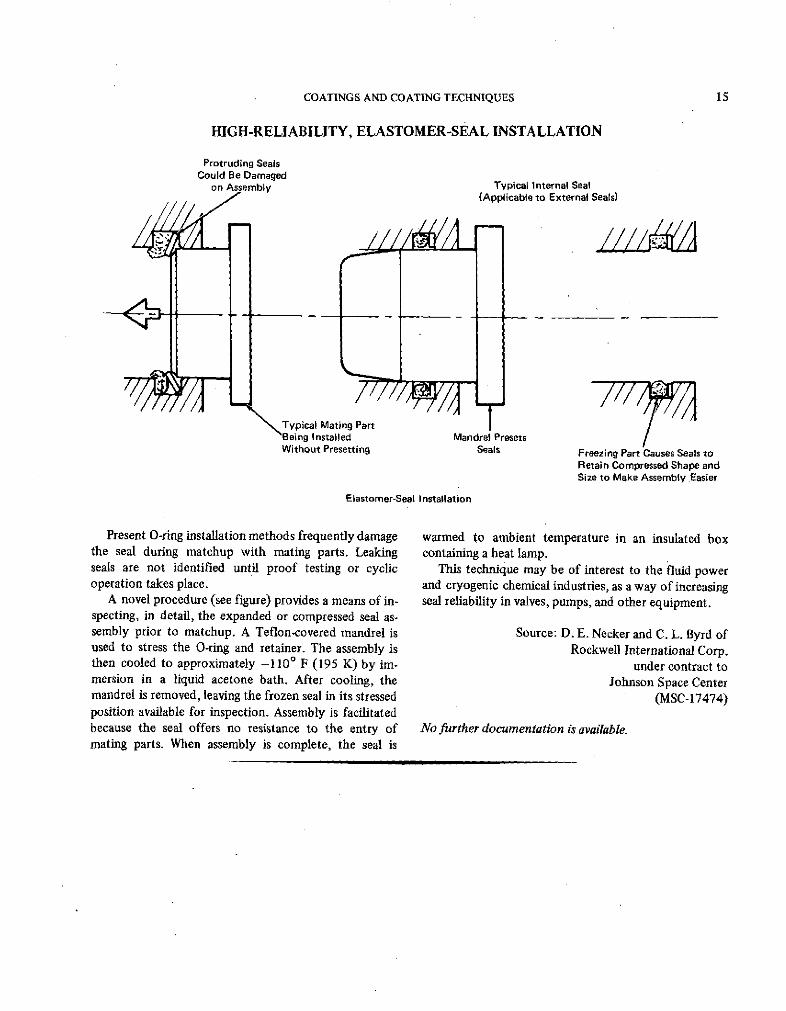
HIGH-RELIABILITY, ELASTOMER-SEAL INSTALLATION
Protruding SealsCould Be Damaged
on Assembly Typical Internal Seal(Applicable to External Seals)
Typical Mating PartBeing Installed Mandrel PresetsWithout Presetting Seals Freezing Part Causes Seals to
Retain Compressed Shape andSize to Make Assembly Easier
Elastomer-Seal Installation
Present O-ring installation methods frequently damage warmed to ambient temperature in an insulated boxthe seal during matchup with mating parts. Leaking containing a heat lamp.seals are not identified until proof testing or cyclic This technique may be of interest to the fluid poweroperation takes place. and cryogenic chemical industries, as a way of increasing
A novel procedure (see figure) provides a means of in- seal reliability in valves, pumps, and other equipment.specting, in detail, the expanded or compressed seal as-sembly prior to matchup. A Teflon-covered mandrel is Source: D. E. Necker and C. L. Byrd ofused to stress the O-ring and retainer. The assembly is Rockwell International Corp.then cooled to approximately -1100 F (195 K) by im- under contract tomersion in a liquid acetone bath. After cooling, the Johnson Space Centermandrel is removed, leaving the frozen seal in its stressed (MSC-17474)position available for inspection. Assembly is facilitatedbecause the seal offers no resistance to the entry of No further documentation is available.mating parts. When assembly is complete, the seal is
16 FABRICATION TECHNOLOGY
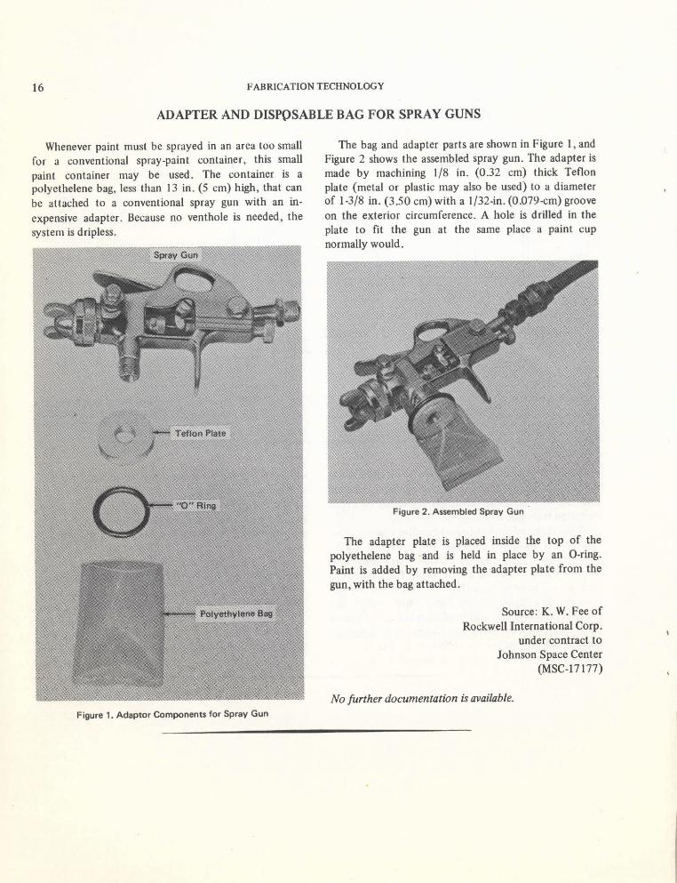
ADAPTER AND DISPOSABLE BAG FOR SPRAY GUNS
Whenever paint must be sprayed in an area too small The bag and adapter parts are shown in Figure 1, and
for a conventional spray-paint container, this small Figure 2 shows the assembled spray gun. The adapter is
paint container may be used. The container is a made by machining 1/8 in. (0.32 cm) thick Teflon
polyethelene bag, less than 13 in. (5 cm) high, that can plate (metal or plastic may also be used) to a diameter
be attached to a conventional spray gun with an in- of 1-3/8 in. (3.50 cm) with a 1/32-in. (0.079-cm) groove
expensive adapter. Because no venthole is needed, the on the exterior circumference. A hole is drilled in the
system is dripless, plate to fit the gun at the same place a paint cupnormally would.
Figure 2. Assembled Spray Gun
The adapter plate is placed inside the top of the
polyethelene bag and is held in place by an O-ring.
Paint is added by removing the adapter plate from the
gun, with the bag attached.
Source: K. W. Fee ofRockwell International Corp.
under contract toJohnson Space Center
(MSC-17177)
No further documentation is available.
Figure 1. Adaptor Components for Spray Gun

COATINGS AND COATING TECHNIQUES 17
A NEW POTTING, SEALING, AND CONFORMAL COATING SYSTEM
Two potting compounds, a seal coat, and a conformal syringe or a caulking gun, and the sealer and coatingcoating have been developed to meet the stringent can be brushed or dipped on. The compounds can berequirements of manned spaceflight. The entire system worked several hours after preparation and will cure atis nonflammable, has a low density, and is easy to room temperature in less than a week. For repairs, therepair. For these reasons, the formulations may be compounds can be removed mechanically without dam-useful in other cases in which quality and safety are aging wires or components.important. The performance of the system meets most of the
One of the potting formulations is an entirely stringent requirements of the space program. Theinorganic mixture, made of asbestos fiber, silica, glass system has a wide temperature range, is an excellentmicroballoons to reduce density, and sodium silicate. insulator, undergoes negligible outgassing, and is moistureThese components are mixed with a silica aquasol and resistant and flexible.cast into a mold. The asbestos fiber lends added strengthand the microballoons contribute to ease of repair. The following documentation may be obtained from:
The second potting compound is a primarily in- National Technical Information Serviceorganic system having a nonflammable fluorinated Springfield, Virginia 22151elastomer as the binder. The formulation consists Single document price $3.00primarily of the fluorelastomer, asbestos, and glass (or microfiche $1.45)microballoons. Methyl ethyl ketone and methyl isobutyl Reference: NASA-CR-108492 (N70-33745), Develop-ketone are used as solvents. ment of Inorganic Nonflammable Spacecraft Potting,
Both potting compounds require a sealer coat. For Encapsulating, and Conformal Coating Compoundsthis purpose, a mixture of fluorelastomer, magnesiumoxide, and tabular alumina are used. Methyl ethyl Source: S. H. Foster andketone is the solvent for the sealer. K. H. Lothrop of
The conformal coating is a mixture of a brominated Emerson and Cuming Inc.polyester, tabular alimina (a filler), and a small amount under contract toof cobalt napthenate (to aid in the cure). The coating is Johnson Space Centerapplied without a solvent to reduce porosity. (MSC-13479)
The system lends itself to most fabrication tech-niques; the potting compounds can be applied with a
APPLICATION OF A SOFT-ANODIZING PROCESS FOR OPTICAL INSTRUMENTS
A soft-anodizing process for optical instruments can where properties such as outgassing, flaking, and chip-produce surfaces comparable to those coated with ping cannot be tolerated, and where the special featuresblack velvet paint in its ability to absorb light at large of instruments such as knife edges must be maintainedangles of incidence. Advantages of the process over at the highest level of efficiency.paint are: (a) paint outgasses more than anodizing,(b) paint is more susceptible to flaking, chipping and Source: J. F. Wade ofscratching than anodizing and (c) paint has a tendency Martin Marietta Corp.to seek sharp edges, while anodizing does not. under contract to
The primary application of the process is in the field Marshall Space Flight Centerof optical instruments used over long periods of time in (MFS-20365)i remote environment where maintenance cannot beconveniently performed. It is also intended for use Circle 8 on Reader Service Card.
18 FABRICATION TECHNOLOGY
Section 4. Miscellaneous Fabrication Techniques
GLASS CAPILLARY TUBE CUTTER AND SEALER
Funnel CapillaryTube
Upper Sleeve
Finger Set ScrewGrip Re,.sistive
WirePivot
Capillary Screw
Tube
AI
Detail "A"Pivot (Enlarged)
LowerSleeve
Tension ElectricalSpring Leads
Capillary Tube Cutter and Sealer
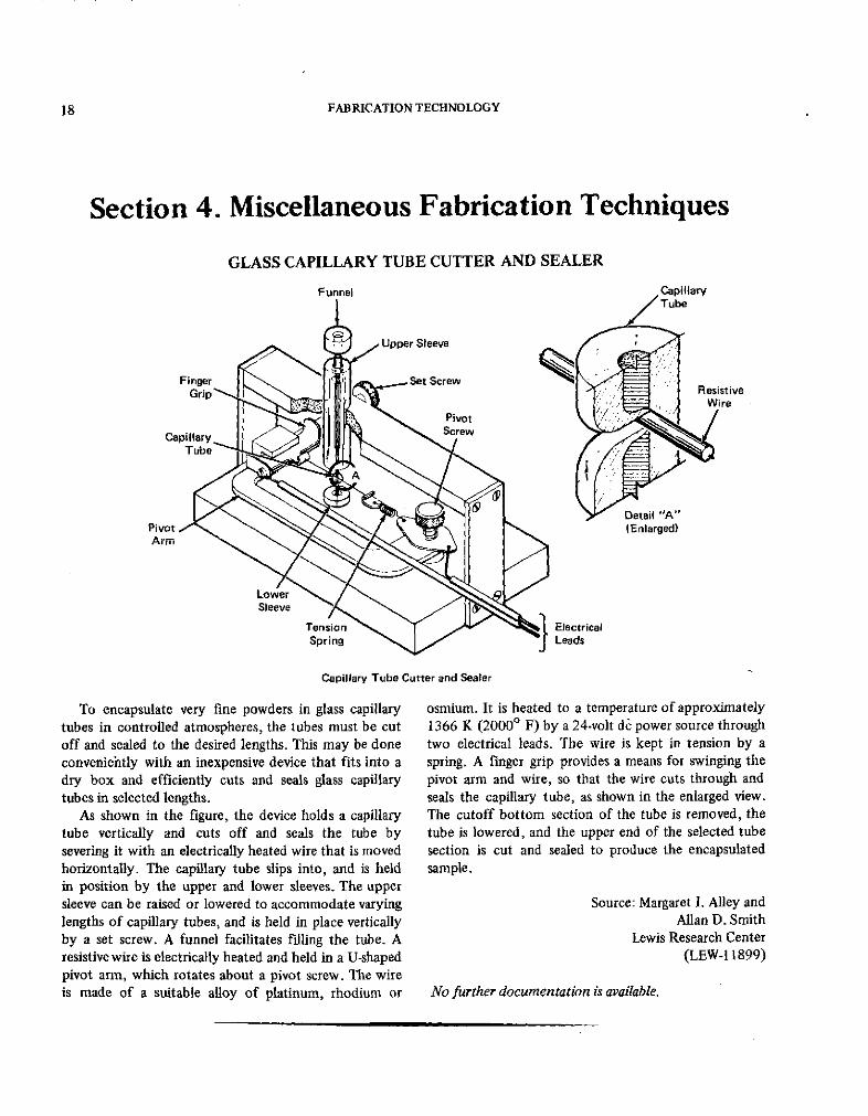
To encapsulate very fine powders in glass capillary osmium. It is heated to a temperature of approximatelytubes in controlled atmospheres, the tubes must be cut 1366 K (20000 F) by a 24-volt dc power source throughoff and sealed to the desired lengths. This may be done two electrical leads. The wire is kept in tension by aconveniehtly with an inexpensive device that fits into a spring. A finger grip provides a means for swinging thedry box and efficiently cuts and seals glass capillary pivot arm and wire, so that the wire cuts through andtubes in selected lengths. seals the capillary tube, as shown in the enlarged view.
As shown in the figure, the device holds a capillary The cutoff bottom section of the tube is removed, thetube vertically and cuts off and seals the tube by tube is lowered, and the upper end of the selected tubesevering it with an electrically heated wire that is moved section is cut and sealed to produce the encapsulatedhorizontally. The capillary tube slips into, and is held sample.in position by the upper and lower sleeves. The uppersleeve can be raised or lowered to accommodate varying Source: Margaret I. Alley andlengths of capillary tubes, and is held in place vertically Allan D. Smithby a set screw. A funnel facilitates filling the tube. A Lewis Research Centerresistive wire is electrically heated and held in a U-shaped (LEW-1 1899)pivot arm, which rotates about a pivot screw. The wireis made of a suitable alloy of platinum, rhodium or No further documentation is available.

MISCELLANEOUS FABRICATION TECHNIQUES 19
REDUCTION OF STIFFNESS REQUIREMENTS FOR FLAT FRAMES
Free-End Rotation
5.0-Frame Rotation(Numerical Method)
4.0 -
E'N Frame Rotationa Z(Emperical Design Method)
3.0-
0 Maximum IDeflection
< of Uniformly2.0 - Loaded Beam
1.0 -Fixed-EndRotation
0I I I
0 0.2 0.4 0.6 0.8 1.0k (Constant for Frames)
Comparison of Constants for Beam and Frame Equations
Large flat surfaces on structures such as aircraft are An expression for intermediate cases has been derivedsupported by frames. Standard references present the and found to be dependent on a parameter k, a functiondesigner two criteria for selecting the proper frame of the end moment. This parameter can be determinedstrength: (1) the frames may have fixed ends, or (2) the by comparing frame stiffness to the elastic behavior ofends of the frames may have complete freedom of beams. These two expressions have nearly the same ratiorotation. In practice, the ends of the frames frequently of fixed-to-free end conditions and have matchingmust have a limited but definite ability to rotate. intermediate points (see figure). From this relationship
As a result, designers usually must choose the criterion and from the expressions for beams and frames, it isfor free frame ends. This conservative choice is structur- fouind that k is related to the maximum deflection of aally safe, but can be a case of extreme overdesign. frame under a unit load and can be considered a spring
A new design approach fills the gap in the available constant. With this knowledge, intermediate values cantechniques for determining frame stiffness. It may be be determined by interpolation with an empirical designapplied to symmetric and nonsymmetric frame ends, equation, derived from the expressions for fixed beamsincluding all cases intermediate between fixed and free. and frames.
These design equations are based on the standard-reference expressions for frame stiffness for the two Source: H. Birnbaum andconditions: fixed and free rotation. The equations are J. W. Warren ofderived from the solution of a fourth-order differential Rockwell International Corp.equation. Approximate solutions are available in the under contract toliterature, however, only for the cases of fixed or free Johnson Space Centerrotation. (MSC-17789)
Circle 9 on Reader Service Card.

20 FABRICATION TECHNOLOGY
LOW-RESISTANCE CONTACTS FOR SOLAR CELLS
Diffused Silicon Cell
Diffused Silicon Cell
Surface-to-SurfaceContact Between
E lecoe Cell and Lead
T u n g st e n
Electrode
Negative Electrical Lead Positive Electrical Lead
Lead for Front of Cell Lead for Back of Cell
A Possible Solar Cell Configuration Using Tungsten Contact Electrodes
A new method improves the fabrication of low- back of the cell. The figure shows how the surface of theresistance contacts for diffused-silicon cells. It has lead is joined with the surface of the cell.several advantages over the deposition of silver/titanium The difference between this new technique and oldercontacts and other existing methods. Silver/titanium methods is primarily due to the formation of a W-Si-Ocontacts frequently separate from the cell at low low-resistivity compound that provides an integral junc-temperatures, under a vacuum, or at high humidity. tion rather than a surface-adhesive layer. The tungstenTungsten contacts, deposited on the cells by any of may be deposited by standard methods such as evapo-several techniques, overcome many of the problems ration, sputtering, or compression or diffusion bonding.associated with the silver/titanium system. In addition, The electrical connections may be made by joining thethis new type of contact can be used with integrated- tungsten electrode to foils, wires, or expanded foils ofcircuit chips as well. tungsten or other materials. This may be done by
Advantages of the tungsten-electrode contact include: inert-gas welding, arc welding, resistance welding, ora. The contact is unaffected by humidity, vacuum, similar processes.
severe temperature variations, and other environ- The following procedure is recommended for fabrica-mental factors. tion of the tungsten-electrode contacts:
b. The tungsten-electrode contacts have a very low a. The diffused-silicon cell is masked to provide thecontact resistance that enhances the electrical power desired contact-electrode configuratioh (see figure).output and efficiency of the cell. b. The exposed portion is polished, sandblasted, or
c. The low contact resistance of the tungsten electrode chemically etched. (Care must be taken not to removeallows the use of low-resistance solar cells in environ- the diffused p-n junction of the cell.) The cell isments with intense electromagnetic radiation (the then degreased and cleaned.Van Allen belts, for instance). c. One of the standard processes is used to deposit theSolar cells require two leads: Normally, a negative tungsten.
lead on the front of the cell and a positive lead on the
MISCELLANEOUS FABRICATION TECHNIQUES 21
d. The cells with the contact electrodes are annealed to Source: Joseph Epsteincomplete the formation of the W-Si-O compound. If Goddard Space Flight Centerthe preceding deposition process required heating (GSC-10695)(e.g., sputtering or diffusion bonding), there is noneed to heat at this point. No further documentation is available.
A TECHNIQUE FOR ADDING SOLDER BUMPS TO INTEGRATED CIRCUIT CHIPS
Fly-wire binding costs are a significant portion of the containing molten solder. The vacuum is released sudden-assembly costs of integrated and hybrid circuits. In ly. The abrupt increase in pressure forces the moltenaddition, fly wires are a major source of failures, solder through the holes in the photoresist layer and
Several methods have been considered for adding into contact with the metal pads.solderable metallurgy to off-the-shelf silicon integratedcircuits (SIC's). Metal-stencil-mask vacuum deposition, Source: J. F. Burgess,for instance, has been found uneconomical unless the R. F. Girard, C. A. Neugebauer,circuit geometry is expanded. However, solder bumps 3 and C. J. Watters ofto 4 mils (0.0075 to 0.01 cm) thick can be economically General Electric Co.made with this new process. under contract to
The passivated wafers are etched to uncover the metal Johnson Space Centerpads, and the solder is vacuum deposited on the pads (MSC-14402)through a photoresist pattern. For the vacuum de-position, the wafers are placed in a vacuum chamber Circle 10 on Reader Service Card.
GRAPHS OF STRESS AND TENSION PROPERTIES OF BOLTS
A new set of graphs describes the allowable loads for use. They are particularly useful because the relativestructural bolts under combined tension and shear. The strengths of bolts are much more apparent from thesegraphs have been developed to aid in the design of graphs than from calculations or tables.ground-support equipment at Kennedy Space Center.They are a more handy reference than tables, and thus Source: James R. Douglas ofallow design engineers to select the proper bolt quickly, The Boeing Co.without resorting to laborious calculations. under contract to
The allowable, loads are calculated from standard Kennedy Space Centerstress equations. The graphs cover standard ASTM bolts (KSC-10493)of several grades and sizes. Therefore, the data arereliable and inclusive, yet are convenient and easy to Circle 11 on Reader Service Card.
22
Patent InformationThe following innovations, described in this Compilation, have been patented or are
being considered for patent action as indicated below:
Fabrication of Irregular Surface Shapes (Page 8) MFS-22205Inquiries concerning rights for the commercial use of this invention should be
addressed to:Patent CounselMarshall Space Flight CenterCode CCO IMarshall Space Flight Center, Alabama 35812
Low-Resistance Contacts for Solar Cells (Page 20) GSC-10695This invention has been patented by NASA (US. Patent No. 3,664,874). Inquiries
concerning nonexclusive or exclusive license for its commercial development should beaddressed to:
Patent CounselGoddard Space Flight CenterCode 204Greenbelt, Maryland 20771