Sequences spanning the EcoRI substrate site David E.Garfin ...
Upload
chengjun-wangCategory
view
213download
0
Fd
CBa
b
a
ARR1AA
KNIDEE
1
lDDifbi[cdnptrreifd
0d
Colloids and Surfaces B: Biointerfaces 69 (2009) 99–104
Contents lists available at ScienceDirect
Colloids and Surfaces B: Biointerfaces
journa l homepage: www.e lsev ier .com/ locate /co lsur fb
abrication of the nanogapped gold nanoparticles film for direct electricaletection of DNA and EcoRI endonuclease
hengjun Wanga,b, Jiarui Huanga, Jin Wanga, Cuiping Gua, Junhai Wanga,uchang Zhangb, Jinhuai Liua,∗
Institute of Intelligent Machines, Chinese Academy of Sciences, Anhui 230031, People’s Republic of ChinaSchool of Life Science, Anhui University, Anhui 230039, People’s Republic of China
r t i c l e i n f o
rticle history:eceived 8 July 2008eceived in revised form4 November 2008ccepted 14 November 2008
a b s t r a c t
In situ seeding growth of gold nanoparticles (AuNPs) by the reaction of HAuCl4 and NH2OH has beenemployed in the fabrication of the nanogapped AuNPs film for direct electrical detection of DNA hybridiza-tion and DNA cleavage by EcoRI endonuclease. The distance between neighboring gold nanoparticles isless than the length of the probe DNA, implying that the DNA strand could bridge the AuNPs to pro-vide an electron tunneling path between microelectrodes. The double-stranded DNA (dsDNA) formed by
vailable online 24 November 2008eywords:anogapped gold nanoparticles film
n situ seeding growthNA
hybridization of probe and target DNA is detected by current–voltage (I–V) curve measurements. WhendsDNA is cleaved by restriction endonuclease EcoRI, the electron tunneling path can be cut off, which isreflected from the different slopes of I–V curves between dsDNA and dsDNA cleavage by EcoRI in the label-free electrical measurements. The novel and simple method of fabricating the nanogapped AuNPs filmby in situ seeding growth could provide a promising bioanalytical platform for studying both DNA–DNA
tions.
coRI endonucleaselectrical detectionand DNA–protein interac
. Introduction
Gene engineering plays an important role in the field of modernife science. It generates a growing demand, in particular for tests ofNA hybridization and DNA–protein interactions. The detection ofNA hybridization becomes increasingly important for applications
ncluding point-of-care diagnostics, environmental monitoring andorensic analysis. Although DNA had been regarded as insulator,ased on charge transfer via stacked aromatic bases (�–� stack-
ng) in DNA molecule, the DNA electrical conductivity was proposed1,2]. Compared to some other traditional technologies such as opti-al [3], electrochemical [4] and gravimetric [5] methods, electricaletection of DNA [6–8] has been recognized as a promising tech-ique because of its straightforwardness in signal interfacing androcessing as well as in the integration of a DNA microarray sys-em. On the other hand, DNA–protein interactions play importantoles in life processes, such as DNA replication, transcription andepair. EcoRI endonuclease is among the simplest site-specific DNA
nzymes and it is useful for the study of the mechanisms govern-ng the interaction of such proteins with DNA [9,10]. The enzymeunctions as a homodimer of a 31-kDa polypeptide [11], and intro-uces two staggered, single-strand scissions into the symmetric∗ Corresponding author. Tel.: +86 551 5591142; fax: +86 551 5592420.E-mail address: [email protected] (J. Liu).
927-7765/$ – see front matter © 2008 Elsevier B.V. All rights reserved.oi:10.1016/j.colsurfb.2008.11.008
© 2008 Elsevier B.V. All rights reserved.
recognition sequence, 5′-GAATTC-3′ [12]. Up to date, many stud-ies about DNA–EcoRI interaction have been performed by atomicforce microscopy [13], cantilevers [14], optical detection [15], gelelectrophoresis [16] and electrochemical detection [17]. However,few works about the electrical detection of DNA–EcoRI interactionhave been done.
The development in the field of nano- and molecular electron-ics depends greatly on the ability to fabricate nanometer-sizedgaps between electrodes [18,19]. It is difficult to fabricate struc-tures smaller than 10 nm with current lithography methods, andeven more challenging to build the gap which should be equalor slightly less than the length of the biomolecule. In this con-nection, precise control of the electrode gap in nanometer rangeis a crucial factor for DNA electrical detection. As a gap adap-tor, the gold nanoparticle which has been widely applied inDNA sensing [20–22], was used to address this issue. Mirkin’sgroup reported that AuNPs were captured in between micrometer-gapped electrodes by the hybridization of DNA strands. Then silverdeposition facilitated by the gold nanoparticles bridged the gapand led to electrical detection of DNA indirectly [23]. Shiigi etal. [24] developed another method, i.e., utilizing alkylthiol as a
cross-linker to fabricate a nano-gapped gold particle film con-sisting of gold nanoparticle–alkylchain–gold nanoparticle repeatedsequences. Tsai et al. [25] built up the second layer of AuNPs usinghexanedithiol as a cross-linker and detected the electrical signal ofDNA strands immobilized on self-assembled multilayer AuNPs.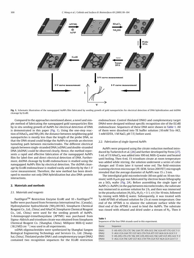
100 C. Wang et al. / Colloids and Surfaces B: Biointerfaces 69 (2009) 99–104
F growc
pbitnttsDsfimnacoi
2
2
bHRC3SC(
Bhc
1 mM APTMS of ethanol solution for 2 h at room temperature. Oneend of the APTMS is to silanize the substrate surface while thethiol end of the APTMS is used to bind the AuNPs. The substratewas rinsed with ethanol and dried under a stream of N2. Then it
Table 1Sequences of the four DNA strands used in this experiment.
ig. 1. Schematic illustration of the nanogapped AuNPs film fabricated by seedingleavage by EcoRI.
Compared to the approaches mentioned above, a novel and sim-le method of fabricating the nanogapped gold nanoparticles filmy in situ seeding growth of AuNPs for electrical detection of DNAs demonstrated in this paper (Fig. 1). Using the one-step reac-ion of HAuCl4 and NH2OH, the distance between neighboring goldanoparticles is mostly less than the length of the probe DNA, sohat the DNA strand could bridge the AuNPs to provide an electronunneling path between microelectrodes. The different electricalignals between single-stranded DNA (ssDNA) and double-strandedNA (dsDNA) could be observed clearly. Hence, the method repre-
ents a rapid and effective fabrication of the nanogapped AuNPslm for label-free and direct electrical detection of DNA. Further-ore, dsDNA cleavage by EcoRI endonuclease is studied using the
anogapped AuNPs film by electrical detection. The dsDNA cleav-ge by EcoRI endonuclease is studied easily and directly by the I–Vurve measurement. Therefore, the new method has been devel-ped to monitor not only DNA hybridization but also DNA–proteinnteractions.
. Materials and methods
.1. Materials and reagents
FastDigestTM Restriction Enzyme EcoRI and 10 × FastDigestTM
uffer were purchased from Fermentas International Inc. (Canada).ydroxylamine hydrochloride (NH2OH·HCl, Sinopharm Chemicaleagent Co., Ltd., China) and HAuCl4 (Sinopharm Chemical Reagento., Ltd., China) were used for the seeding growth of AuNPs.-Aminopropyl-trimethoxysilane (APTMS) was purchased fromigma–Aldrich and trisodium citrate was obtained from Sinopharmhemical Reagent Co. (Shanghai, China). Millipore Milli-Q water
18.2 M� cm−1) was used in all experiments.ssDNA oligonucleotides were synthesized by Shanghai Sangoniological Engineering Technology and Services Co., Ltd. (Shang-ai, China). Thiolated probe DNA1 and complementary target DNA2ontained two recognition sequences for the ECoRI restriction
th of gold nanoparticles for electrical detection of DNA hybridization and dsDNA
endonuclease. Control thiolated DNA3 and complementary targetDNA4 were designed without specific recognition site of the ECoRIendonuclease. Sequences of these DNA were shown in Table 1. Allof them were dissolved into TE buffer solution (10 mM Tris–HCl,1 mM EDTA, 1 M NaCl, pH 7.5) before used.
2.2. Fabrication of single-layered AuNPs
AuNPs were prepared using the citrate reduction method intro-duced by Turkevitch et al. [26] and further developed by Frens [27].1 mL of 1% HAuCl4 was added into 100 mL Milli-Q water and heateduntil boiling. Then 4 mL 1% trisodium citrate at room temperaturewas added while stirring, the solution underwent a series of colorchanges and 15 min later it turned wine red. The field-emissionscanning electron microscope (FE-SEM, Sirion 200 FET) micrographrevealed that the average diameter of AuNPs was 15 ± 3 nm.
The interdigital gold microelectrode (60 nm gold on 10 nm tita-nium) with 8 �m gap was fabricated by electron beam lithographyon a SiO2 wafer (Fig. 2A). Before assembling the single layer ofAuNPs (s-AuNPs) in the gap between microelectrodes, the substratewas immersed in acetone solution for 2 h, and then was immersedin the piranha solution (H2SO4:H2O2 = 3:1, v/v) for 10 min, followedby rinsing with Milli-Q water. Subsequently, it was treated with
Name Sequence
DNA1 5′-HS-ATG CTG CTC TAC GAA TTC ATA GCG TAC GGA ATT CTG GCC T-3′
DNA2 5′-AGG CCA GAA TTC CGT ACG CTA TGA ATT CGT AGA GCA GCA T-3′
DNA3 5′-HS-ATG CTG CTC TAC ATC GTA ATA GCG TAC GAT CGT ATG GCC T-3′
DNA4 5′-AGG CCA TAC GAT CGT ACG CTA TTA CGA TGT AGA GCA GCA T-3′

C. Wang et al. / Colloids and Surfaces B: Biointerfaces 69 (2009) 99–104 101
F in thes ctrodeg
wM
2
tsoctssttwom
2
sobeba
pmtdww
wD
ig. 2. FE-SEM images of the electrodes: (A) the interdigitated microelectrode used-AuNPs before seeding growth between electrodes; (D) the sg-AuNPs between elerowth of 2 min; and (F) the sg-AuNPs between electrodes after growth of 3 min.
as immersed in the prepared AuNPs solution for 8 h, rinsed withilli-Q water and dried with N2.
.3. In situ seeding growth of gold nanoparticles
The solution for AuNPs seeding growth was prepared by mixingogether 0.01% HAuCl4 and 0.4 mM NH2OH·HCl freshly. The sub-trate was placed in a clean Pyrex dish followed by the additionf the seeding growth solution. The reaction was allowed to pro-eed for 2 min at 28 ◦C while continuously agitating the Pyrex disho swirl the solution over the substrate surface. After removal, theurface was immediately washed with Milli-Q water, dried under atream of N2. The distance between AuNPs was dependent on theotal reaction time, which ensured the controllability of the dis-ance. As the reaction time increased, the distance between AuNPsas decreased. The seeding grown gold nanoparticles (sg-AuNPs)n the substrate surface were monitored with the scanning electronicroscope.
.4. DNA probe immobilization and hybridization
After the microelectrode was immobilized with monolayer ofg-AuNPs, thiolated probe DNA1 was then assembled on the surfacef sg-AuNP by Au–S bond. 5 �L solution of 10 �M probe DNA1 in TEuffer (pH 7.5) was added to the substrate and kept it in a humidnvironment at 35 ◦C for 1 h. Then the substrate was rinsed with TEuffer to remove the unlinked and weakly adsorbed probe DNA1nd dried with N2.
5 �l TE buffer involving 100 nM target DNA2 which was com-lemented to the probe DNA1 strand was pipetted onto the DNA1odified substrate, and proceeding for 2 h at 37 ◦C. Hybridiza-
ion occurred between DNA1 and DNA2 in the solution to formsDNA on the surface of AuNPs. Then the substrate was rinsed
ith TE buffer to remove the unbound target DNA2 and driedith N2.The microelectrode, which had s-AuNPs before seeding growth,as immobilized with probe DNA1 and hybridized with targetNA2 in order to be compared with the one containing sg-AuNPs.
experiment; (B) assembled with s-AuNPs after the silanization treatment; (C) thes after in situ seeding growth of 1 min; (E) the sg-AuNPs between electrodes after
2.5. Enzyme cleavage of surface-immobilized dsDNA
The Fermentas FastDigestTM Restriction Enzyme EcoRI, whichwas specifically formulated to cleave DNA in just 5 min, wasused in the experiment. The digestion media, which was pre-pared using 1 �L of EcoRI (1 FDU/�L) and 2 �L enzyme reactionbuffer (10 × FastDigestTM buffer), was placed on the dsDNA oligonu-cleotides immobilized microelectrode and incubated in a dark,humid environment for 5 min at 37 ◦C. Then the microelectrodesurface was washed with Milli-Q water, dried under a stream ofN2.
Control probe DNA3 and complementary target DNA4 whichwere designed without specific recognition site of the EcoRIendonuclease were used under the same treatment. Enzyme reac-tion buffer was placed on the dsDNA immobilized microelectrodeonly as a control experiment.
2.6. Electrical measurements
The current–voltage (I–V) curve was measured by a picoamme-ter voltage sourcemeter (Keithley 6487, USA) with a bias voltagefrom −1.5 V to 1.5 V. All electrical measurements were performedunder the N2 condition using a Faraday copper cage at 25 ◦C.
3. Results and discussion
3.1. Characterization the nanogapped AuNPs film betweenmicroelectrodes
After performing the s-AuNPs between microelectrodes, the insitu growth of gold nanoparticles was achieved by treatment with afreshly prepared solution containing HAuCl4 and NH2OH·HCl. Theincrease of the size of AuNPs in the catalytic growth process could
cause the change of the optical or electronic properties of AuNPs[28]. The catalytic growth of AuNPs has been employed in sev-eral DNA analytical methods [23,29–32]. The seeding approach isan excellent route to enlargement of gold nanoparticles. Natan’sgroup had used hydroxylamine to enlarge gold nanoparticles in
102 C. Wang et al. / Colloids and Surfaces B: Biointerfaces 69 (2009) 99–104
F (A) clv particd aps).
siAedraip
ctebibDtbisa1dnststtdntfi
ig. 3. SEM imaging analysis of gold nanoparticles and the distance between AuNPs:iew of the sg-AuNPs between electrodes after 2 min seeding growth; (C) the nanoistance between AuNPs before and after 2 min seeding growth (50 analyzed nanog
olution [28,33] and form conductive gold films from particlesmmobilized on a substrate [34]. On the basis of the colloidalu surface-catalyzed reduction of Au3+ by NH2OH, a method fornlargement of colloidal gold nanoparticles called “seeding” isescribed herein. While NH2OH is thermodynamically capable ofeducing Au3+ to bulk metal, the reaction is dramatically acceler-ted by Au surfaces. As a result, no new particle nucleation occursn solution, and all added Au3+ participates in producing largerarticles [28].
The growth of gold nanoparticles between microelectrodes isonveniently observed by FE-SEM. As Fig. 2B and C illustrate,he s-AuNPs are uniformly deposited in the gap between micro-lectrodes with a silanization treatment. However, the distanceetween neighboring s-AuNPs is usually more than 13 nm (Fig. 3A)
n comparison with the length (13 nm) of the DNA strand (40ase pairs) in the present experiment. It is suggested that theNA strand cannot bridge s-AuNPs due to the long relative dis-
ance between neighboring s-AuNPs. Fig. 2D displays the sg-AuNPsetween microelectrodes after 1 min growth. The size of sg-AuNP
s increased a very little, and the distance between neighboringg-AuNPs is almost not decreased. After 2 min seeding growth,s shown in Fig. 2E, the size of the sg-AuNP is increased (from5 ± 3 to 28 ± 4 nm; Fig. 3C) and the distance between sg-AuNPs isecreased (from 16 ± 5 to 8 ± 3 nm; Fig. 3D). The distance betweeneighboring sg-AuNPs is less than 10 nm (Fig. 3B). Hence, the DNAtrand can bridge the neighboring sg-AuNPs to provide an elec-ron tunneling path between microelectrodes. Fig. 2F shows theg-AuNPs after 3 min growth, the sg-AuNPs become too large, sohat the neighboring sg-AuNPs join together to form the electron
unneling path between microelectrodes. In order to control theistance less than 10 nm so that the DNA strand can bridge theeighboring sg-AuNPs, the gold nanoparticles with the growthime of 2 min was chosen to fabricate the nanogapped AuNPslm.ose-up view of the s-AuNPs between electrodes before seeding growth; (B) close-uple diameters of s-AuNP and sg-AuNP (50 analyzed nanoparticles); (D) the nanogap
3.2. Electrical detection of DNA using the AuNPs film
Two interdigital gold microelectrodes containing s-AuNPs andsg-AuNPs film, respectively, were used to detect DNA hybridiza-tion by I–V measurements. Fig. 4A shows I–V curves of s-AuNPsbefore growth between microelectrodes. The curves a, b, and c rep-resent I–V responses of bare s-AuNPs, s-AuNPs with ssDNA (probeDNA1), and s-AuNPs with dsDNA, respectively. When the thiolatedprobe DNA1 is immobilized on the s-AuNPs, the electric currentof s-AuNPs with ssDNA is higher than the current of bare s-AuNPs(curves a and b). However, the magnitude and slope of the curves band c are very close, which implies that there is no electrical signaldifference between ssDNA and dsDNA. The distance between neigh-boring s-AuNPs is more than 13 nm, whereas the length of the DNAstrand is 13 nm. Therefore the DNA strand cannot bridge the neigh-boring s-AuNPs to form an electron tunneling path. No significantelectrical difference between ssDNA and dsDNA with s-AuNPs inI–V measurements can be observed.
From above I–V measurements, it is concluded that the s-AuNPsfilm cannot detect the 40 bp DNA because the distance neighbor-ing s-AuNPs is more than the length of the DNA strand. The I–Vmeasurements for sg-AuNPs after 2 min seeding growth are shownin Fig. 4B. Compared Fig. 4A with B, the current magnitude of sg-AuNPs is significantly higher than that of s-AuNPs, which could beascribed as the in situ seeding growth of s-AuNPs providing morechances for electrons to tunnel between microelectrodes. Addition-ally, as shown from curves a and c, bare sg-AuNPs have the lowestelectric current, whereas sg-AuNPs with ds-DNA have the highestelectric current. As mentioned above, the distance between two
neighboring sg-AuNPs is less than 10 nm after the seeding growthof s-AuNPs. Thus, the free end of a DNA string immobilized onone AuNP can lie on a random neighboring AuNPs. The electroncan flow through the ss-DNA and nanoparticles so as to form anelectron tunneling path between microelectrodes. The neighboring
C. Wang et al. / Colloids and Surfaces B: Biointerfaces 69 (2009) 99–104 103
FAcw
st�etttcq
3
dtditnDuti
apn
Fig. 5. Electrical detection of DNA–EcoRI interaction using the sg-AuNPs film: (A)I–V measurements for dsDNA cleavage by EcoRI using the sg-AuNPs film: (a) baresg-AuNPs, (b) sg-AuNPs with ss-DNA (probe DNA1), (c) sg-AuNPs with ds-DNA, (d)
ig. 4. Electrical detection of DNA using different AuNPs films: (A) I–V curves of s-uNPs: (a) bare s-AuNPs, (b) s-AuNPs with ss-DNA, (c) s-AuNPs with ds-DNA; (B) I–Vurves of sg-AuNPs: (a) bare sg-AuNPs, (b) sg-AuNPs with ss-DNA and (c) sg-AuNPsith ds-DNA.
g-AuNPs can be considered to be multiple tiny electrodes wherehe DNA strand can propagate electrons. Moreover, more compact–� stacking in hybridized dsDNA could contribute to forminglectron delocalization, so the double-stranded DNA provides addi-ional electron tunneling path and has higher electric current thanhe signal-stranded DNA. As shown from curves b and c, the elec-ric current difference between ssDNA and dsDNA can be observedlearly, which implies that the microelectrode with sg-AuNPs isuite suitable for DNA electrical detection.
.3. Electrical detection of dsDNA cleavage by EcoRI
When the DNA strand can bridge the neighboring sg-AuNPs,sDNA is detected directly by the I–V curve measurement. Fur-her research of the microelectrode, which has sg-AuNPs andsDNA, is the detection of some other biomolecules that have
nteractions with DNA. The simple and easy choice is EcoRI restric-ion endonuclease, which can recognize and bind to specificucleotide sequences (5′-GAATTC-3′) resulting in cleavage of theNA molecule. In this work, short dsDNA oligonucleotides weresed as model DNA to study dsDNA cleavage by EcoRI. The motiva-ion of this work is to propose a new approach to study DNA–protein
nteraction for research application.I–V curves of sg-AuNPs with dsDNA and dsDNA with EcoRIre shown in Fig. 5A compared to the curves c and d. Thiolatedrobe DNA1 and complementary target DNA2 contain two recog-ition sequences for the EcoRI endonuclease. Hence the dsDNA
dsDNA with EcoRI. (B) Control measurements for assaying the cleavage specificity ofEcoRI endonuclease: (a) bare sg-AuNPs, (b) sg-AuNPs with ss-DNA (probe DNA3), (c)sg-AuNPs with ds-DNA, (d) dsDNA with EcoRI, and (e) dsDNA with enzyme reactionbuffer.
formed by hybridization of DNA1 and DNA2 is cleaved at two spe-cific sites and the electron tunneling path made by dsDNA is cutoff completely. The electric current decreases after the sg-AuNPswith dsDNA treated with EcoRI for 5 min. The current magnitudeof dsDNA with EcoRI is higher than bare sg-AuNPs and lower thansg-AuNPs with ssDNA (curves d, a and b).
In the present work, dsDNA cleavage by EcoRI is investigatedreal-time, which is monitored by detecting the change of I–V sig-nals with the increasing time. Fig. 6 shows real-time I–V curves afterdigestion with EcoRI. The curves a and g represent I–V responsesof sg-AuNPs with dsDNA and bare sg-AuNPs, respectively. Afterimmersed in enzymatic cleavage mixture, the electric currentdecreased with the increasing time, indicating that EcoRI cleav-age occurred. As seen from curve b to f, the electric current hasa rapid decrease after adding EcoRI in the first 3 min (curves b, cand d), then the current decreases slowly as time lapsed and startsto level off above 5 min (curves e and f), indicating that dsDNA iscleaved by EcoRI after 5 min of enzyme reaction time. In order toprove that the decrease in electric current is a result of scission and
not be affected by any other reasons, two control experiments wereperformed below.As is well known, EcoRI is a site-specific endonuclease whichrecognizes the sequence GAATTC. To evaluate this, control probeDNA3 and target DNA4 were selected to assay the cleavage speci-

104 C. Wang et al. / Colloids and Surfaces B:
F(
ficaorwnatttWtobta
4
aAsbblbsseItTDp
[
[
[
[
[[[[[[[
[[
ig. 6. I–V measurements for dsDNA cleavage by EcoRI at different reaction times:a) 0, (b) 1 min, (c) 2 min, (d) 3 min, (e) 4 min, (f) 5 min, and (g) bare sg-AuNPs.
city of EcoRI endonuclease. DNA3 and DNA4 were designed asontrol DNA without specific recognization site of EcoRI endonucle-se. Thiolated control probe DNA3 was immobilized on the surfacef sg-AuNPs and hybridized with DNA4. As shown in Fig. 5B, theesults of DNA immobilization and hybridization are in accordanceith the results obtained above. However, the electric current doesot decrease in the presence of EcoRI; furthermore, the magnitudend slope of the curves c and d are very close. That is, the electronunneling path made by dsDNA is not cut off by EcoRI, suggestinghat EcoRI has no effect on the DNA3 and DNA4 hybrid without con-aining specific recognition sequence for the EcoRI endonuclease.
hen the enzyme reaction buffer was placed on the dsDNA only,he electric current does not decrease and the magnitude and slopef the curves c and e are very close. It is concluded that enzymeuffer has no effect on electrical detection of dsDNA. From two con-rol experiments, the decrease in conductivity is clearly suggesteds a result of DNA scission.
. Conclusions
In summary, a novel method for detecting the DNA hybridizationnd DNA–EcoRI interaction is demonstrated using the nanogappeduNPs film by in situ seeding growth of AuNPs. The DNA stranderved as a nanogap bridge provides an electron tunneling pathetween microelectrodes because of the appropriate distanceetween neighboring gold nanoparticles in comparison with the
ength of DNA. The sg-AuNPs microelectrode identifies dsDNAy I–V curve measurements when dsDNA is immobilized on theurface of sg-AuNPs after hybridization of the probe and targetsDNA. If dsDNA is cleaved by restriction endonuclease EcoRI, thelectron tunneling path made by the DNA strand is cut off. The
–V curve change is used to characterize dsDNA–EcoRI interac-ion directly and the cleavage specificity has been investigated.he new method will be meaningful for the label-free detection ofNA–DNA and DNA–protein interactions, which builds up a newlatform for studying biological processes. Finally, because this[
[[
Biointerfaces 69 (2009) 99–104
platform is based on one conventional microelectrode, it wouldbecome the DNA and protein biochips of massive multiplexingand high throughput through the use of large arrays of microelec-trodes.
Acknowledgements
This work was partially supported by National Natural Sci-ence Foundation of China (60574095, 60711120174), NationalHigh Technology Research and Development Program of China(2006AA03Z309), the Young College Teachers’ Research FundProgram of Anhui province (2007jql060zd) and the Knowl-edge Innovation Program of the Chinese Academy of Science(0723A15121).
References
[1] M.R. Arkin, E.D.A. Stemp, R.E. Holmlin, J.K. Barton, A. Hormann, E.J.C. Olson, P.F.Barbara, Science 273 (1996) 475.
[2] D.B. Hall, R.E. Holmlin, J.K. Barton, Nature 382 (1996) 731.[3] I. Alexandre, S. Hamels, S. Dufour, J. Collet, N. Zammatteo, F. De Longueville, J.-L.
Gala, J. Remacle, Anal. Biochem. 295 (2001) 1.[4] M. Steichen, Y. Decrem, E. Godfroid, C. Buess-Herman, Biosens. Bioelectron. 22
(2007) 2237.[5] V.C.H. Wu, S.H. Chen, C.S. Lin, Biosens. Bioelectron. 22 (2007) 2967.[6] S. Roy, H. Vedala, A.D. Roy, D-h. Kim, M. Doud, K. Mathee, H-k. Shin, N. Shi-
mamoto, V. Prasad, W. Choi, Nano Lett. 8 (2008) 26.[7] B. Xu, P. Zhang, X. Li, N. Tao, Nano Lett. 4 (2004) 1105.[8] D. Berdat, A.C.M. Rodríguez, F. Herrera, M.A.M. Gijs, Lab Chip 8 (2008) 302.[9] J. Heitman, P. Model, Proteins 7 (1990) 185.
[10] M. Kurpiewski, L. Engler, L. Wozniak, A. Kobylanska, M. Koziolkiewicz, W. Stec,L. Jen-Jacobson, Structure 12 (2004) 1775.
[11] Y. Kim, J.C. Grable, R. Love, P.J. Greene, J.M. Rosenberg, Science 249 (1990) 1307.12] J. Hedgpeth, H.M. Goodman, H.W. Boyer, Proc. Natl. Acad. Sci. U.S.A. 80 (1972)
31.[13] J.C. O’Brien, J.T. Stickney, M.D. Porter, J. Am. Chem. Soc. 122 (2000) 5004.[14] Y. Weizmann, R. Elnathan, O. Lioubashevski, I. Willner, J. Am. Chem. Soc. 127
(2005) 12666.[15] H. Watrob, W. Liu, Y. Chen, S.G. Bartlett, L. Jen-Jacobson, M.D. Barkley, Biochem-
istry 40 (2001) 683.[16] B. Polisky, P. Greene, D. Garfin, B. Mcarthy, H. Goodman, H. Boyer, Proc. Natl.
Acad. Sci. U.S.A. 72 (1975) 3310.[17] Y. Jin, W. Lu, J.Q. Hu, X. Yao, J.H. Li, Electrochem. Commun. 9 (2007) 1086.[18] A. Nitzan, M.A. Ratner, Science 300 (2003) 1384.[19] K.W. Hipps, Science 294 (2001) 536.20] J.J. Storhoff, A.A. Lazarides, R.C. Mucic, C.A. Mirkin, R.L. Letsinger, G.C. Schatz, J.
Am. Chem. Soc. 122 (2000) 4640.21] J.J. Storhoff, R. Elghanian, R.C. Mucic, C.A. Mirkin, R.L. Letsinger, J. Am. Chem.
Soc. 120 (1998) 1959.22] B.M. Reinhard, S. Sheikholeslami, A. Mastroianni, A.P. Alivisatos, J. Liphardt,
Proc. Natl. Acad. Sci. U.S.A. 104 (2007) 2667.23] S.J. Park, T.A. Taton, C.A. Mirkin, Science 295 (2002) 1503.24] H. Shiigi, S. Tokonami, H. Yakabe, T. Nagaoka, J. Am. Chem. Soc. 127 (2005) 3280.25] C.Y. Tsai, T.L. Chang, L.S. Kuo, P.H. Chen, Appl. Phys. Lett. 89 (2006) 203902.26] J. Turkevitch, P.C. Stevenson, J. Hillier, Discuss. Faraday Soc. 11 (1951) 55.27] G. Frens, Nat. Phys. Sci. 241 (1973) 20.28] K.R. Brown, M.J. Natan, Langmuir 14 (1998) 726.29] X.H. Yang, Q. Wang, K.M. Wang, W.H. Tan, H.M. Li, Biosens. Bioelectron. 22
(2007) 1106.30] I. Willner, F. Patolsky, Y. Weizmann, B. Willner, Talanta 56 (2002) 847.31] G. Festag, T. Schüler, R. Möller, A. Csáki, W. Fritzsche, Nanotechnology 19 (2008)
125303.32] E. Diessel, K. Grothe, H.M. Siebert, B.D. Waarner, J. Burmeister, Biosens. Bioelec-
tron. 19 (2004) 1229.33] K.R. Brown, D.G. Walter, M.J. Natan, Chem. Mater. 12 (2000) 306.34] K.R. Brown, L.A. Lyon, A.P. Fox, B.D. Reiss, M.J. Natan, Chem. Mater. 12 (2000)
314.