Fabrication of Pancharatnam-Berry phase optical...
11
Fabrication of Pancharatnam-Berry phase optical elements with highly stable polarization holography TAO ZHAN, JIANGHAO XIONG, YUN-HAN LEE, RAN CHEN, AND SHIN-TSON WU * CREOL, The College of Optics and Photonics, University of Central Florida, Orlando, FL 32816, USA *[email protected] Abstract: Polarization-dependent diffraction based on Pancharatnam-Berry phase optical elements (PBOEs) offers considerable benefits compared to conventional metasurfaces, such as negligible absorption, nearly 100% diffraction efficiency and an inexpensive fabrication process. Polarization holography is a simple way to fabricate PBOEs, which entails the interference of beams with different polarizations to generate a spatial-varying polarization field. Thus, the quality of recorded PBOEs manifests high sensitivity to the length change and phase shift between polarized beams, usually caused by environmental vibration and air flow. Here, new polarization holography based on modified Sagnac interferometry is developed for fabricating liquid crystal–based PB gratings and lenses, where the pitch of grating and optical power of lens could be easily tuned. This approach offers high tolerance to environmental disturbance during the exposure process. Detailed design parameters are analyzed, and the fabricated PBOEs with high optical quality are also demonstrated. © 2019 Optical Society of America under the terms of the OSA Open Access Publishing Agreement 1. Introduction Conventionally, the phase change of an electromagnetic wave is generated via wave propagation through spatial-varying optical path lengths, which is also known as the the dynamic phase. Since the phase change is gradually accumulated along the optical path, the dimension of these optical elements is usually much larger compared to the wavelength of light. Recently, various kinds of flat, ultra-thin optical elements have been developed based on Pancharatnam-Berry (PB) phase, which can provide abrupt phase change over the scale of free space wavelength [1]. These planar ‘metasurfaces’ could be generated by plasmatic metamaterials [2–4], sub-wavelength isotropic gratings [5–7], propagation from reflections [8] and optical anisotropy [9–11]. Among all the methods mentioned above, PB optical elements (PBOEs) fabricated by photo-alignment of liquid crystals and photo-polymerization method [12–14] manifests a nearly 100% diffraction efficiency and excellent optical quality. As a result, PBOEs have found widespread applications, such as beam steering [15–19], polarimetry [20,21], projection [22], zoom lens [23–26] and even near-eye displays [27–33]. There are mainly four steps in the established fabrication methods of liquid-crystal-based PBOEs. Firstly, a thin film of photo-alignment material is spin-coated on a glass substrate. Next, the coated substrate is exposed to the pre-designed polarization light field with sufficient exposure dosage. After that, a thin layer of diluted liquid crystal reactive mesogen is coated onto the surface alignment layer. Finally, the substrate is dried and exposed with UV to form a cross-linked liquid crystal polymer film. Phase profiles of the desired PBOE are entirely determined by the polarized light field generated through interference. Thus, the quality of fabricated PBOE is highly dependent on that of polarization hologram. A common way to fabricate PBOEs is to generate polarization holography by the interference from a double-path interferometer of two circularly polarized beams with opposite handedness. Thus, a laser with single-longitudinal mode and ultra-short linewidth is Vol. 27, No. 3 | 4 Feb 2019 | OPTICS EXPRESS 2632 #349889 Journal © 2019 https://doi.org/10.1364/OE.27.002632 Received 2 Nov 2018; revised 17 Dec 2018; accepted 20 Dec 2018; published 28 Jan 2019
Transcript of Fabrication of Pancharatnam-Berry phase optical...
Fabrication of Pancharatnam-Berry phase optical elements with highly stable polarization holography
TAO ZHAN, JIANGHAO XIONG, YUN-HAN LEE, RAN CHEN, AND SHIN-TSON WU
* CREOL, The College of Optics and Photonics, University of Central Florida, Orlando, FL 32816, USA *[email protected]
Abstract: Polarization-dependent diffraction based on Pancharatnam-Berry phase optical elements (PBOEs) offers considerable benefits compared to conventional metasurfaces, such as negligible absorption, nearly 100% diffraction efficiency and an inexpensive fabrication process. Polarization holography is a simple way to fabricate PBOEs, which entails the interference of beams with different polarizations to generate a spatial-varying polarization field. Thus, the quality of recorded PBOEs manifests high sensitivity to the length change and phase shift between polarized beams, usually caused by environmental vibration and air flow. Here, new polarization holography based on modified Sagnac interferometry is developed for fabricating liquid crystal–based PB gratings and lenses, where the pitch of grating and optical power of lens could be easily tuned. This approach offers high tolerance to environmental disturbance during the exposure process. Detailed design parameters are analyzed, and the fabricated PBOEs with high optical quality are also demonstrated.
© 2019 Optical Society of America under the terms of the OSA Open Access Publishing Agreement
1. Introduction
Conventionally, the phase change of an electromagnetic wave is generated via wave propagation through spatial-varying optical path lengths, which is also known as the the dynamic phase. Since the phase change is gradually accumulated along the optical path, the dimension of these optical elements is usually much larger compared to the wavelength of light. Recently, various kinds of flat, ultra-thin optical elements have been developed based on Pancharatnam-Berry (PB) phase, which can provide abrupt phase change over the scale of free space wavelength [1]. These planar ‘metasurfaces’ could be generated by plasmatic metamaterials [2–4], sub-wavelength isotropic gratings [5–7], propagation from reflections [8] and optical anisotropy [9–11]. Among all the methods mentioned above, PB optical elements (PBOEs) fabricated by photo-alignment of liquid crystals and photo-polymerization method [12–14] manifests a nearly 100% diffraction efficiency and excellent optical quality. As a result, PBOEs have found widespread applications, such as beam steering [15–19], polarimetry [20,21], projection [22], zoom lens [23–26] and even near-eye displays [27–33].
There are mainly four steps in the established fabrication methods of liquid-crystal-based PBOEs. Firstly, a thin film of photo-alignment material is spin-coated on a glass substrate. Next, the coated substrate is exposed to the pre-designed polarization light field with sufficient exposure dosage. After that, a thin layer of diluted liquid crystal reactive mesogen is coated onto the surface alignment layer. Finally, the substrate is dried and exposed with UV to form a cross-linked liquid crystal polymer film. Phase profiles of the desired PBOE are entirely determined by the polarized light field generated through interference. Thus, the quality of fabricated PBOE is highly dependent on that of polarization hologram.
A common way to fabricate PBOEs is to generate polarization holography by the interference from a double-path interferometer of two circularly polarized beams with opposite handedness. Thus, a laser with single-longitudinal mode and ultra-short linewidth is
Vol. 27, No. 3 | 4 Feb 2019 | OPTICS EXPRESS 2632
#349889 Journal © 2019
https://doi.org/10.1364/OE.27.002632 Received 2 Nov 2018; revised 17 Dec 2018; accepted 20 Dec 2018; published 28 Jan 2019
necessary to obtain adequate coherence length because the optical path difference between the two arms cannot be guaranteed to be zero. Also, double-path interferometers are highly sensitive to phase shifts or length changes between the two arms, rendering environmental vibration which is one of the leading causes of fabrication failures. So, an enclosed vibration-isolated optical table is usually needed to prevent the vibration and perturbations from air currents, which makes the setups more complicated and expensive.
In this paper, we demonstrate a versatile polarization holography setup based on Sagnac interferometry for the fabrication of PBOEs. Thanks to its extraordinary stability, the Sagnac interferometer has been exploited for numerous applications, including but not limited to conventional holography [34,35], holographic microscopy [36,37] and even gravitational wave detection [38]. Here, we modify it as a common-path exposure setup for PBOEs with much higher tolerance to environmental perturbations, while requiring fewer optics and a shorter coherence length of the laser source. Firstly, the detailed designs of the proposed holography setups based on common-path interferometers are illustrated, and then the relationship between the setup parameters and sample properties are analyzed. After that the fabricated PB gratings and lenses are characterized, which exhibits nearly 100% diffraction efficiency and high optical quality with negligible haze, verifying the feasibility and advantages of the proposed polarization holography setups.
2. Polarization holography designs
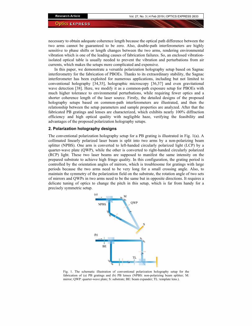
The conventional polarization holography setup for a PB grating is illustrated in Fig. 1(a). A collimated linearly polarized laser beam is split into two arms by a non-polarizing beam splitter (NPBS). One arm is converted to left-handed circularly polarized light (LCP) by a quarter-wave plate (QWP), while the other is converted to right-handed circularly polarized (RCP) light. These two laser beams are supposed to manifest the same intensity on the prepared substrate to achieve high fringe quality. In this configuration, the grating period is controlled by the orientation angles of mirrors, which is troublesome for gratings with large periods because the two arms need to be very long for a small crossing angle. Also, to maintain the symmetry of the polarization field on the substrate, the rotation angle of two sets of mirrors and QWPs in two arms need to be the same but in opposite directions. It requires a delicate tuning of optics to change the pitch in this setup, which is far from handy for a precisely symmetric setup.
Fig. 1. The schematic illustration of conventional polarization holography setup for the fabrication of (a) PB gratings and (b) PB lenses (NPBS: non-polarizing beam splitter; M: mirror; QWP: quarter-wave plate; S: substrate; BE: beam expander; TL: template lens.).
Vol. 27, No. 3 | 4 Feb 2019 | OPTICS EXPRESS 2633
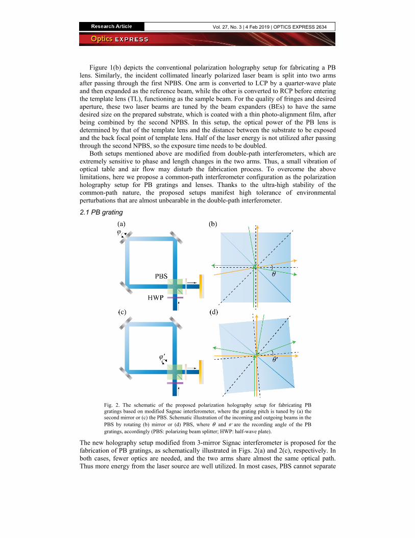
Figure 1(b) depicts the conventional polarization holography setup for fabricating a PB lens. Similarly, the incident collimated linearly polarized laser beam is split into two arms after passing through the first NPBS. One arm is converted to LCP by a quarter-wave plate and then expanded as the reference beam, while the other is converted to RCP before entering the template lens (TL), functioning as the sample beam. For the quality of fringes and desired aperture, these two laser beams are tuned by the beam expanders (BEs) to have the same desired size on the prepared substrate, which is coated with a thin photo-alignment film, after being combined by the second NPBS. In this setup, the optical power of the PB lens is determined by that of the template lens and the distance between the substrate to be exposed and the back focal point of template lens. Half of the laser energy is not utilized after passing through the second NPBS, so the exposure time needs to be doubled.
Both setups mentioned above are modified from double-path interferometers, which are extremely sensitive to phase and length changes in the two arms. Thus, a small vibration of optical table and air flow may disturb the fabrication process. To overcome the above limitations, here we propose a common-path interferometer configuration as the polarization holography setup for PB gratings and lenses. Thanks to the ultra-high stability of the common-path nature, the proposed setups manifest high tolerance of environmental perturbations that are almost unbearable in the double-path interferometer.
2.1 PB grating
Fig. 2. The schematic of the proposed polarization holography setup for fabricating PB gratings based on modified Sagnac interferometer, where the grating pitch is tuned by (a) the second mirror or (c) the PBS. Schematic illustration of the incoming and outgoing beams in the PBS by rotating (b) mirror or (d) PBS, where θ and 'θ are the recording angle of the PB gratings, accordingly (PBS: polarizing beam splitter; HWP: half-wave plate).
The new holography setup modified from 3-mirror Signac interferometer is proposed for the fabrication of PB gratings, as schematically illustrated in Figs. 2(a) and 2(c), respectively. In both cases, fewer optics are needed, and the two arms share almost the same optical path. Thus more energy from the laser source are well utilized. In most cases, PBS cannot separate
Vol. 27, No. 3 | 4 Feb 2019 | OPTICS EXPRESS 2634
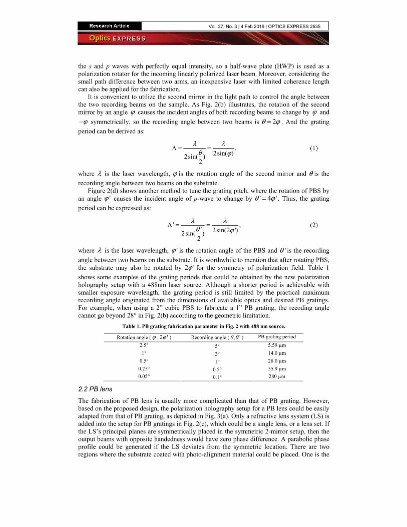
the s and p waves with perfectly equal intensity, so a half-wave plate (HWP) is used as a polarization rotator for the incoming linearly polarized laser beam. Moreover, considering the small path difference between two arms, an inexpensive laser with limited coherence length can also be applied for the fabrication.
It is convenient to utilize the second mirror in the light path to control the angle between the two recording beams on the sample. As Fig. 2(b) illustrates, the rotation of the second mirror by an angle ϕ causes the incident angles of both recording beams to change by ϕ and
ϕ− symmetrically, so the recording angle between two beams is 2θ ϕ= . And the grating
period can be derived as:
,2sin( )2sin( )
2
λ λθ ϕ
Λ = = (1)
where λ is the laser wavelength, ϕ is the rotation angle of the second mirror and θ is the
recording angle between two beams on the substrate. Figure 2(d) shows another method to tune the grating pitch, where the rotation of PBS by
an angle 'ϕ causes the incident angle of p-wave to change by ' 4 'θ ϕ= . Thus, the grating
period can be expressed as:
' ,' 2sin(2 ')2sin( )
2
λ λθ ϕ
Λ = = (2)
where λ is the laser wavelength, 'ϕ is the rotation angle of the PBS and 'θ is the recording
angle between two beams on the substrate. It is worthwhile to mention that after rotating PBS, the substrate may also be rotated by 2 'ϕ for the symmetry of polarization field. Table 1
shows some examples of the grating periods that could be obtained by the new polarization holography setup with a 488nm laser source. Although a shorter period is achievable with smaller exposure wavelength, the grating period is still limited by the practical maximum recording angle originated from the dimensions of available optics and desired PB gratings. For example, when using a 2” cubic PBS to fabricate a 1” PB grating, the recoding angle cannot go beyond 28° in Fig. 2(b) according to the geometric limitation.
Table 1. PB grating fabrication parameter in Fig. 2 with 488 nm source.
Rotation angle ( ϕ , 2 'ϕ ) Recording angle ( , 'θ θ ) PB grating period
2.5° 5° 5.59 µm
1° 2° 14.0 µm
0.5° 1° 28.0 µm
0.25° 0.5° 55.9 µm
0.05° 0.1° 280 µm
2.2 PB lens
The fabrication of PB lens is usually more complicated than that of PB grating. However, based on the proposed design, the polarization holography setup for a PB lens could be easily adapted from that of PB grating, as depicted in Fig. 3(a). Only a refractive lens system (LS) is added into the setup for PB gratings in Fig. 2(c), which could be a single lens, or a lens set. If the LS’s principal planes are symmetrically placed in the symmetric 2-mirror setup, then the output beams with opposite handedness would have zero phase difference. A parabolic phase profile could be generated if the LS deviates from the symmetric location. There are two regions where the substrate coated with photo-alignment material could be placed. One is the
Vol. 27, No. 3 | 4 Feb 2019 | OPTICS EXPRESS 2635
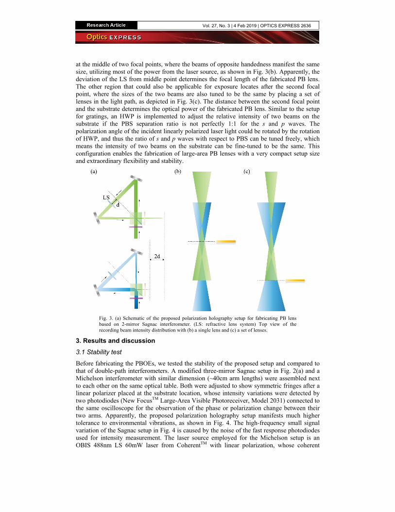
at the middle of two focal points, where the beams of opposite handedness manifest the same size, utilizing most of the power from the laser source, as shown in Fig. 3(b). Apparently, the deviation of the LS from middle point determines the focal length of the fabricated PB lens. The other region that could also be applicable for exposure locates after the second focal point, where the sizes of the two beams are also tuned to be the same by placing a set of lenses in the light path, as depicted in Fig. 3(c). The distance between the second focal point and the substrate determines the optical power of the fabricated PB lens. Similar to the setup for gratings, an HWP is implemented to adjust the relative intensity of two beams on the substrate if the PBS separation ratio is not perfectly 1:1 for the s and p waves. The polarization angle of the incident linearly polarized laser light could be rotated by the rotation of HWP, and thus the ratio of s and p waves with respect to PBS can be tuned freely, which means the intensity of two beams on the substrate can be fine-tuned to be the same. This configuration enables the fabrication of large-area PB lenses with a very compact setup size and extraordinary flexibility and stability.
Fig. 3. (a) Schematic of the proposed polarization holography setup for fabricating PB lens based on 2-mirror Sagnac interferometer. (LS: refractive lens system) Top view of the recording beam intensity distribution with (b) a single lens and (c) a set of lenses.
3. Results and discussion
3.1 Stability test
Before fabricating the PBOEs, we tested the stability of the proposed setup and compared to that of double-path interferometers. A modified three-mirror Sagnac setup in Fig. 2(a) and a Michelson interferometer with similar dimension (~40cm arm lengths) were assembled next to each other on the same optical table. Both were adjusted to show symmetric fringes after a linear polarizer placed at the substrate location, whose intensity variations were detected by two photodiodes (New FocusTM Large-Area Visible Photoreceiver, Model 2031) connected to the same oscilloscope for the observation of the phase or polarization change between their two arms. Apparently, the proposed polarization holography setup manifests much higher tolerance to environmental vibrations, as shown in Fig. 4. The high-frequency small signal variation of the Sagnac setup in Fig. 4 is caused by the noise of the fast response photodiodes used for intensity measurement. The laser source employed for the Michelson setup is an OBIS 488nm LS 60mW laser from CoherentTM with linear polarization, whose coherent
Vol. 27, No. 3 | 4 Feb 2019 | OPTICS EXPRESS 2636
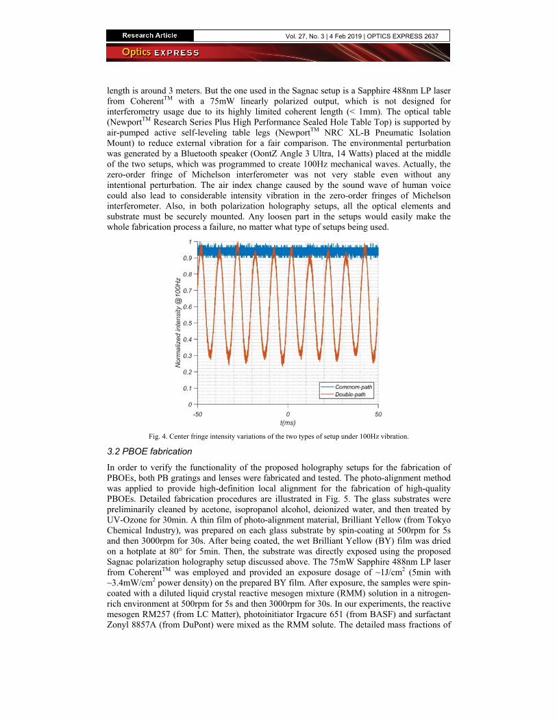
length is around 3 meters. But the one used in the Sagnac setup is a Sapphire 488nm LP laser from CoherentTM with a 75mW linearly polarized output, which is not designed for interferometry usage due to its highly limited coherent length (< 1mm). The optical table (NewportTM Research Series Plus High Performance Sealed Hole Table Top) is supported by air-pumped active self-leveling table legs (NewportTM NRC XL-B Pneumatic Isolation Mount) to reduce external vibration for a fair comparison. The environmental perturbation was generated by a Bluetooth speaker (OontZ Angle 3 Ultra, 14 Watts) placed at the middle of the two setups, which was programmed to create 100Hz mechanical waves. Actually, the zero-order fringe of Michelson interferometer was not very stable even without any intentional perturbation. The air index change caused by the sound wave of human voice could also lead to considerable intensity vibration in the zero-order fringes of Michelson interferometer. Also, in both polarization holography setups, all the optical elements and substrate must be securely mounted. Any loosen part in the setups would easily make the whole fabrication process a failure, no matter what type of setups being used.
Fig. 4. Center fringe intensity variations of the two types of setup under 100Hz vibration.
3.2 PBOE fabrication
In order to verify the functionality of the proposed holography setups for the fabrication of PBOEs, both PB gratings and lenses were fabricated and tested. The photo-alignment method was applied to provide high-definition local alignment for the fabrication of high-quality PBOEs. Detailed fabrication procedures are illustrated in Fig. 5. The glass substrates were preliminarily cleaned by acetone, isopropanol alcohol, deionized water, and then treated by UV-Ozone for 30min. A thin film of photo-alignment material, Brilliant Yellow (from Tokyo Chemical Industry), was prepared on each glass substrate by spin-coating at 500rpm for 5s and then 3000rpm for 30s. After being coated, the wet Brilliant Yellow (BY) film was dried on a hotplate at 80° for 5min. Then, the substrate was directly exposed using the proposed Sagnac polarization holography setup discussed above. The 75mW Sapphire 488nm LP laser from CoherentTM was employed and provided an exposure dosage of ~1J/cm2 (5min with ~3.4mW/cm2 power density) on the prepared BY film. After exposure, the samples were spin-coated with a diluted liquid crystal reactive mesogen mixture (RMM) solution in a nitrogen-rich environment at 500rpm for 5s and then 3000rpm for 30s. In our experiments, the reactive mesogen RM257 (from LC Matter), photoinitiator Irgacure 651 (from BASF) and surfactant Zonyl 8857A (from DuPont) were mixed as the RMM solute. The detailed mass fractions of
Vol. 27, No. 3 | 4 Feb 2019 | OPTICS EXPRESS 2637
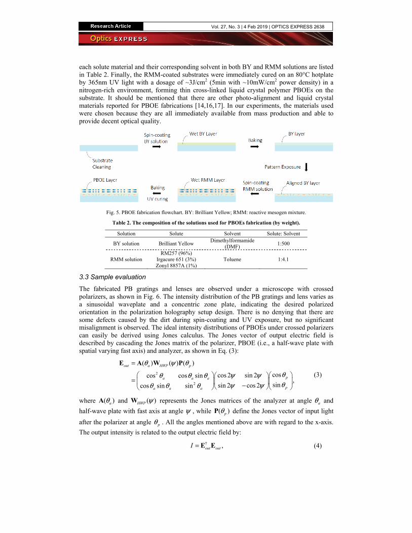
each solute material and their corresponding solvent in both BY and RMM solutions are listed in Table 2. Finally, the RMM-coated substrates were immediately cured on an 80°C hotplate by 365nm UV light with a dosage of ~3J/cm2 (5min with ~10mW/cm2 power density) in a nitrogen-rich environment, forming thin cross-linked liquid crystal polymer PBOEs on the substrate. It should be mentioned that there are other photo-alignment and liquid crystal materials reported for PBOE fabrications [14,16,17]. In our experiments, the materials used were chosen because they are all immediately available from mass production and able to provide decent optical quality.
Fig. 5. PBOE fabrication flowchart. BY: Brilliant Yellow; RMM: reactive mesogen mixture.
Table 2. The composition of the solutions used for PBOEs fabrication (by weight).
Solution Solute Solvent Solute: Solvent
BY solution Brilliant Yellow Dimethylformamide
(DMF) 1:500
RMM solution RM257 (96%)
Irgacure 651 (3%) Zonyl 8857A (1%)
Toluene 1:4.1
3.3 Sample evaluation
The fabricated PB gratings and lenses are observed under a microscope with crossed polarizers, as shown in Fig. 6. The intensity distribution of the PB gratings and lens varies as a sinusoidal waveplate and a concentric zone plate, indicating the desired polarized orientation in the polarization holography setup design. There is no denying that there are some defects caused by the dirt during spin-coating and UV exposure, but no significant misalignment is observed. The ideal intensity distributions of PBOEs under crossed polarizers can easily be derived using Jones calculus. The Jones vector of output electric field is described by cascading the Jones matrix of the polarizer, PBOE (i.e., a half-wave plate with spatial varying fast axis) and analyzer, as shown in Eq. (3):
2
2
( ) ( ) ( )
coscos 2 sin 2cos cos sin,
sinsin 2 cos 2cos sin sin
out a HWP p
pa a a
pa a a
θ ψ θ
θψ ψθ θ θθψ ψθ θ θ
=
= −
E A W P
(3)
where ( )aθA and ( )HWP ψW represents the Jones matrices of the analyzer at angle aθ and
half-wave plate with fast axis at angle ψ , while ( )pθP define the Jones vector of input light
after the polarizer at angle pθ . All the angles mentioned above are with regard to the x-axis.
The output intensity is related to the output electric field by:
† ,out outI = E E (4)
Vol. 27, No. 3 | 4 Feb 2019 | OPTICS EXPRESS 2638
where †outE denotes the Hermitian adjoint of outΕ . When the polarizer and analyzer are
crossed, namely 90pθ = ° and 0aθ = ° , the output intensity can be expressed as:
90 , 0
1 cos(4 )( ) .
2p aIθ θ
ψψ= ° = °−= (5)
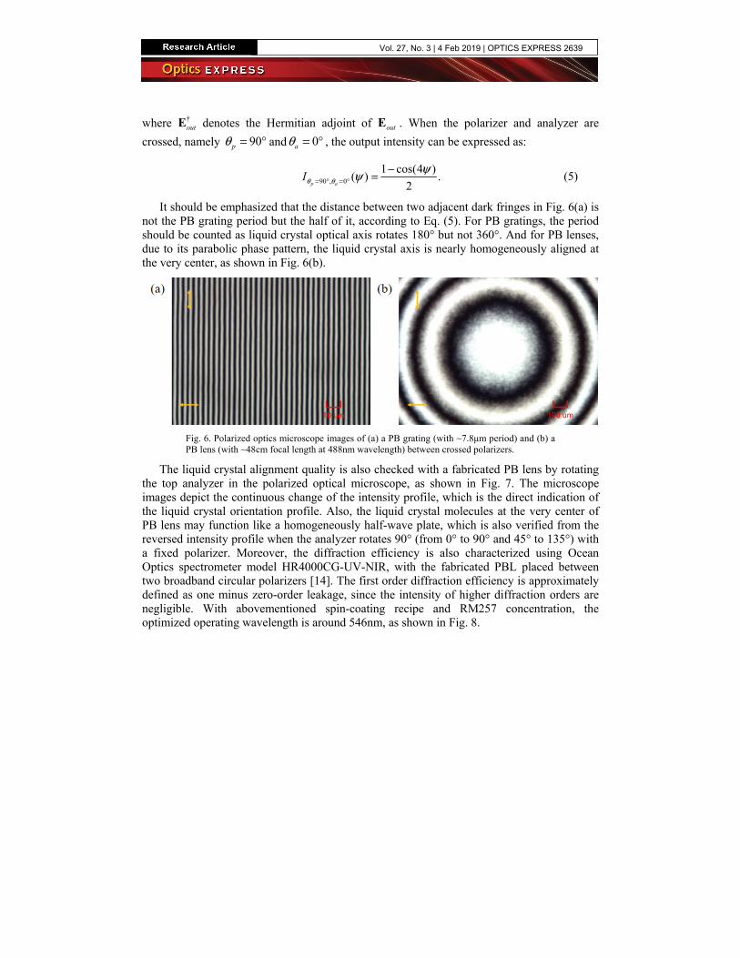
It should be emphasized that the distance between two adjacent dark fringes in Fig. 6(a) is not the PB grating period but the half of it, according to Eq. (5). For PB gratings, the period should be counted as liquid crystal optical axis rotates 180° but not 360°. And for PB lenses, due to its parabolic phase pattern, the liquid crystal axis is nearly homogeneously aligned at the very center, as shown in Fig. 6(b).
Fig. 6. Polarized optics microscope images of (a) a PB grating (with ~7.8μm period) and (b) a PB lens (with ~48cm focal length at 488nm wavelength) between crossed polarizers.
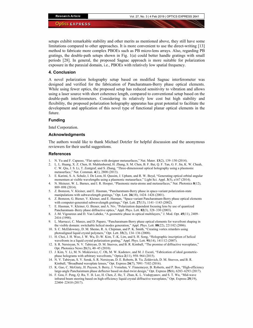
The liquid crystal alignment quality is also checked with a fabricated PB lens by rotating the top analyzer in the polarized optical microscope, as shown in Fig. 7. The microscope images depict the continuous change of the intensity profile, which is the direct indication of the liquid crystal orientation profile. Also, the liquid crystal molecules at the very center of PB lens may function like a homogeneously half-wave plate, which is also verified from the reversed intensity profile when the analyzer rotates 90° (from 0° to 90° and 45° to 135°) with a fixed polarizer. Moreover, the diffraction efficiency is also characterized using Ocean Optics spectrometer model HR4000CG-UV-NIR, with the fabricated PBL placed between two broadband circular polarizers [14]. The first order diffraction efficiency is approximately defined as one minus zero-order leakage, since the intensity of higher diffraction orders are negligible. With abovementioned spin-coating recipe and RM257 concentration, the optimized operating wavelength is around 546nm, as shown in Fig. 8.
Vol. 27, No. 3 | 4 Feb 2019 | OPTICS EXPRESS 2639
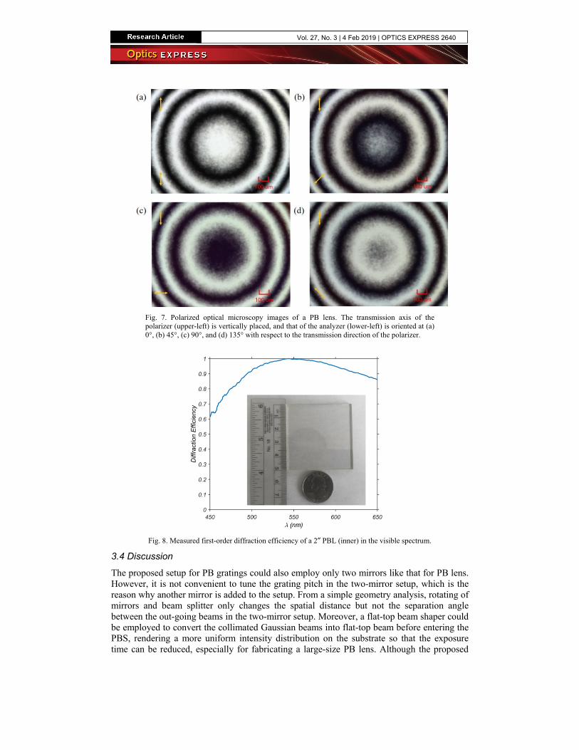
Fig. 7. Polarized optical microscopy images of a PB lens. The transmission axis of the polarizer (upper-left) is vertically placed, and that of the analyzer (lower-left) is oriented at (a) 0°, (b) 45°, (c) 90°, and (d) 135° with respect to the transmission direction of the polarizer.
Fig. 8. Measured first-order diffraction efficiency of a 2″ PBL (inner) in the visible spectrum.
3.4 Discussion
The proposed setup for PB gratings could also employ only two mirrors like that for PB lens. However, it is not convenient to tune the grating pitch in the two-mirror setup, which is the reason why another mirror is added to the setup. From a simple geometry analysis, rotating of mirrors and beam splitter only changes the spatial distance but not the separation angle between the out-going beams in the two-mirror setup. Moreover, a flat-top beam shaper could be employed to convert the collimated Gaussian beams into flat-top beam before entering the PBS, rendering a more uniform intensity distribution on the substrate so that the exposure time can be reduced, especially for fabricating a large-size PB lens. Although the proposed
Vol. 27, No. 3 | 4 Feb 2019 | OPTICS EXPRESS 2640
setups exhibit remarkable stability and other merits as mentioned above, they still have some limitations compared to other approaches. It is more convenient to use the direct-writing [13] method to fabricate more complex PBOEs such as PB micro-lens arrays. Also, regarding PB gratings, the double-path setups shown in Fig. 1(a) could better handle gratings with small periods [28]. In general, the proposed Sagnac approach is more suitable for polarization exposure in the paraxial domain, i.e., PBOEs with relatively low spatial frequency.
4. Conclusion
A novel polarization holography setup based on modified Sagnac interferometer was designed and verified for the fabrication of Pancharatnam-Berry phase optical elements. While using fewer optics, the proposed setup has reduced sensitivity to vibration and allows using a laser source with short coherence length, compared to conventional setup based on the double-path interferometers. Considering its relatively low cost but high stability and flexibility, the proposed polarization holography apparatus has great potential to facilitate the development and application of this novel type of functional planar optical elements in the future.
Funding
Intel Corporation.
Acknowledgments
The authors would like to thank Michael Dotzler for helpful discussion and the anonymous reviewers for their useful suggestions.
References
1. N. Yu and F. Capasso, “Flat optics with designer metasurfaces,” Nat. Mater. 13(2), 139–150 (2014). 2. L. L. Huang, X. Z. Chen, H. Muhlenbernd, H. Zhang, S. M. Chen, B. F. Bai, Q. F. Tan, G. F. Jin, K. W. Cheah,
C. W. Qiu, J. S. Li, T. Zentgraf, and S. Zhang, “Three-dimensional optical holography using a plasmonic metasurface,” Nat. Commun. 4(1), 2808 (2013).
3. E. Karimi, S. A. Schulz, I. De Leon, H. Qassim, J. Upham, and R. W. Boyd, “Generating optical orbital angular momentum at visible wavelengths using a plasmonic metasurface,” Light Sci. Appl. 3(5), e167 (2014).
4. N. Meinzer, W. L. Barnes, and I. R. Hooper, “Plasmonic meta-atoms and metasurfaces,” Nat. Photonics 8(12), 889–898 (2014).
5. Z. Bomzon, V. Kleiner, and E. Hasman, “Pancharatnam-Berry phase in space-variant polarization-state manipulations with subwavelength gratings,” Opt. Lett. 26(18), 1424–1426 (2001).
6. Z. Bomzon, G. Biener, V. Kleiner, and E. Hasman, “Space-variant Pancharatnam-Berry phase optical elements with computer-generated subwavelength gratings,” Opt. Lett. 27(13), 1141–1143 (2002).
7. E. Hasman, V. Kleiner, G. Biener, and A. Niv, “Polarization dependent focusing lens by use of quantized Pancharatnam–Berry phase diffractive optics,” Appl. Phys. Lett. 82(3), 328–330 (2003).
8. J.-M. Vigoureux and D. Van Labeke, “A geometric phase in optical multilayers,” J. Mod. Opt. 45(11), 2409–2416 (1998).
9. L. Marrucci, C. Manzo, and D. Paparo, “Pancharatnam-Berry phase optical elements for wavefront shaping in the visible domain: switchable helical modes generation,” Appl. Phys. Lett. 88(22), 221102 (2006).
10. S. C. McEldowney, D. M. Shemo, R. A. Chipman, and P. K. Smith, “Creating vortex retarders using photoaligned liquid crystal polymers,” Opt. Lett. 33(2), 134–136 (2008).
11. H. Choi, J. H. Woo, J. W. Wu, D.-W. Kim, T.-K. Lim, and S. H. Song, “Holographic inscription of helical wavefronts in a liquid crystal polarization grating,” Appl. Phys. Lett. 91(14), 141112 (2007).
12. S. R. Nersisyan, N. V. Tabiryan, D. M. Steeves, and B. R. Kimball, “The promise of diffractive waveplates,” Opt. Photonics News 21(3), 40–45 (2010).
13. J. Kim, Y. Li, M. N. Miskiewicz, C. Oh, M. W. Kudenov, and M. J. Escuti, “Fabrication of ideal geometric- phase holograms with arbitrary wavefronts,” Optica 2(11), 958–964 (2015).
14. N. V. Tabiryan, S. V. Serak, S. R. Nersisyan, D. E. Roberts, B. Ya. Zeldovich, D. M. Steeves, and B. R. Kimball, “Broadband waveplate lenses,” Opt. Express 24(7), 7091–7102 (2016).
15. K. Gao, C. McGinty, H. Payson, S. Berry, J. Vornehm, V. Finnemeyer, B. Roberts, and P. Bos, “High-efficiency large-angle Pancharatnam phase deflector based on dual-twist design,” Opt. Express 25(6), 6283–6293 (2017).
16. F. Gou, F. Peng, Q. Ru, Y. H. Lee, H. Chen, Z. He, T. Zhan, K. L. Vodopyanov, and S. T. Wu, “Mid-wave infrared beam steering based on high-efficiency liquid crystal diffractive waveplates,” Opt. Express 25(19), 22404–22410 (2017).
Vol. 27, No. 3 | 4 Feb 2019 | OPTICS EXPRESS 2641
17. J. Kim, C. Oh, S. Serati, and M. J. Escuti, “Wide-angle, nonmechanical beam steering with high throughput utilizing polarization gratings,” Appl. Opt. 50(17), 2636–2639 (2011).
18. C. Oh, J. Kim, J. Muth, S. Serati, and M. J. Escuti, “High-throughput continuous beam steering using rotating polarization gratings,” IEEE Photonics Technol. Lett. 22(4), 200–202 (2010).
19. J. Kim, M. N. Miskiewicz, S. Serati, and M. J. Escuti, “Nonmechanical laser beam steering based on polymer polarization gratings: Design optimization and demonstration,” J. Lightwave Technol. 33(10), 2068–2077 (2015).
20. M. W. Kudenov, M. J. Escuti, E. L. Dereniak, and K. Oka, “White-light channeled imaging polarimeter using broadband polarization gratings,” Appl. Opt. 50(15), 2283–2293 (2011).
21. M. W. Kudenov, M. J. Escuti, N. Hagen, E. L. Dereniak, and K. Oka, “Snapshot imaging Mueller matrix polarimeter using polarization gratings,” Opt. Lett. 37(8), 1367–1369 (2012).
22. R. K. Komanduri, W. M. Jones, C. Oh, and M. J. Escuti, “Polarization-independent modulation for projection displays using small-period LC polarization gratings,” J. Soc. Inf. Disp. 15(8), 589–594 (2007).
23. K. Gao, H. H. Cheng, A. Bhowmik, C. McGinty, and P. Bos, “Nonmechanical zoom lens based on the Pancharatnam phase effect,” Appl. Opt. 55(5), 1145–1150 (2016).
24. K. Gao, H. H. Cheng, A. K. Bhowmik, and P. J. Bos, “Thin-film Pancharatnam lens with low f-number and high quality,” Opt. Express 23(20), 26086–26094 (2015).
25. C. Yousefzadeh, A. Jamali, C. McGinty, and P. J. Bos, ““Achromatic limits” of Pancharatnam phase lenses,” Appl. Opt. 57(5), 1151–1158 (2018).
26. K. Gao, Optical simulation and fabrication of Pancharatnam (geometric) phase devices from liquid crystals, Ph.D. dissertation (Kent State University, 2017).
27. Y. H. Lee, G. Tan, T. Zhan, Y. Weng, G. Liu, F. Gou, F. Peng, N. V. Tabiryan, S. Gauza, and S. T. Wu, “Recent progress in Pancharatnam-Berry phase optical elements and the applications for virtual/augmented realities,” Opt. Data Process. Storage 3(1), 79–88 (2017).
28. X. Xiang, J. Kim, R. Komanduri, and M. J. Escuti, “Nanoscale liquid crystal polymer Bragg polarization gratings,” Opt. Express 25(16), 19298–19308 (2017).
29. Y. H. Lee, T. Zhan, and S. T. Wu, “Enhancing the resolution of a near-eye display with a Pancharatnam-Berry phase deflector,” Opt. Lett. 42(22), 4732–4735 (2017).
30. T. Zhan, Y. H. Lee, and S. T. Wu, “High-resolution additive light field near-eye display by switchable Pancharatnam-Berry phase lenses,” Opt. Express 26(4), 4863–4872 (2018).
31. G. Tan, Y. H. Lee, T. Zhan, J. Yang, S. Liu, D. Zhao, and S. T. Wu, “Foveated imaging for near-eye displays,” Opt. Express 26(19), 25076–25085 (2018).
32. Y. H. Lee, G. Tan, K. Yin, T. Zhan, and S. T. Wu, “Compact see-through near-eye display with depth adaption,” J. Soc. Inf. Disp. 26(2), 64–70 (2018).
33. G. Tan, T. Zhan, Y. H. Lee, J. Xiong, and S. T. Wu, “Polarization-multiplexed multiplane display,” Opt. Lett. 43(22), 5651–5654 (2018).
34. D. N. Naik, T. Ezawa, Y. Miyamoto, and M. Takeda, “3-D coherence holography using a modified Sagnac radial shearing interferometer with geometric phase shift,” Opt. Express 17(13), 10633–10641 (2009).
35. D. N. Naik, T. Ezawa, Y. Miyamoto, and M. Takeda, “Real-time coherence holography,” Opt. Express 18(13), 13782–13787 (2010).
36. S. Mahajan, V. Trivedi, P. Vora, V. Chhaniwal, B. Javidi, and A. Anand, “Highly stable digital holographic microscope using Sagnac interferometer,” Opt. Lett. 40(16), 3743–3746 (2015).
37. C. Ma, Y. Li, J. Zhang, P. Li, T. Xi, J. Di, and J. Zhao, “Lateral shearing common-path digital holographic microscopy based on a slightly trapezoid Sagnac interferometer,” Opt. Express 25(12), 13659–13667 (2017).
38. T. Eberle, S. Steinlechner, J. Bauchrowitz, V. Händchen, H. Vahlbruch, M. Mehmet, H. Müller-Ebhardt, and R. Schnabel, “Quantum enhancement of the zero-area Sagnac interferometer topology for gravitational wave detection,” Phys. Rev. Lett. 104(25), 251102 (2010).
Vol. 27, No. 3 | 4 Feb 2019 | OPTICS EXPRESS 2642