Fabrication of a knee-ankle-foot orthosis using ... · (see Page 5, Chapter "Assembling the System...
32
Technical information 5.4.6 Fabrication of a knee-ankle-foot orthosis using thermoplastic technology with CarbonIQ joint system
Transcript of Fabrication of a knee-ankle-foot orthosis using ... · (see Page 5, Chapter "Assembling the System...
Technical information 5.4.6
Fabrication of a knee-ankle-foot orthosisusing thermoplastic technologywith CarbonIQ joint system

Introduction1 3.........................................................................................................................................................Materials and Products Used2 3............................................................................................................................Manufacturing Process 3 4.....................................................................................................................................Mounting the Orthotic Joints3.1 4..................................................................................................................Assembling the System Knee Joints 3.1.1 4.......................................................................................................Assembling the System Ankle Joints3.1.2 5........................................................................................................Fabricating the Plaster Model 3.2 6................................................................................................................Fabricating the Plaster Negative 3.2.1 6............................................................................................................Fabricating the Plaster Positive3.2.2 9...............................................................................................................Modelling the Foot Area3.2.3 10.......................................................................................................................Modelling the Leg Area3.2.4 13........................................................................................................................Preparing the Orthosis for Trial Fitting3.3 14...................................................................................................Preparation for Vacuum Forming3.3.1 14...........................................................................................................Vacuum Forming 3.3.2 15................................................................................................................................Preparing the Orthosis for Trial Fitting3.3.3 16...................................................................................................Trial Fitting3.3.4 20.........................................................................................................................................Completion of the Orthosis3.4 22..................................................................................................................Adjusting the Orthosis3.4.1 22.........................................................................................................................
Appendices4 26........................................................................................................................................................Adaptation Options for the System Ankle Joints4.1 26......................................................................................Thermoplastic: Processing Instructions4.2 27..................................................................................................Measurement Form4.3 28.............................................................................................................................
Table of contents
2
Table of contents
17PA1=* / 17PK1=*

1 IntroductionThis Technical Information is designed to support you as an orthotist when fabricating a lower extremity orthosisusing the CarbonIQ Joint System, consisting of the 17PK1=* System Knee Joint and the 17PA1=* System AnkleJoint. The Technical Information explains all relevant steps from taking measurements on the user all the way todelivery of the completed orthosis.This Technical Information addresses qualified professionals and assumes that these specialists are trained in thehandling of different materials, machines and tools.This Technical Information does not claim to be exhaustive.The appendices to this Technical Information serve as leads only, and particularly the temperature data and processing guidelines for plastics are based on experience and can vary depending on climate and the condition ofthe oven.
2 Materials and Products UsedThe materials and tools required are listed in the following tables. The tables list the materials and tools shown inthe photos within this Technical Information. The prosthetist or orthotist assumes full responsibility when using anyother materials.
Components and DevicesDesignation Reference Number or Article Number Knee joint 17PK1=* Ankle joint 17PA1=* Foot stirrup 17PF1System bar material 605P8=*Small parts: screws, rivets, locking nuts, etc.
Materials Designation Reference Number or Article Number Thermoplastic see Page 27Terry Cloth padding fabric 623P3Space-Tex 623F62Micro-Velcro 623Z4=50-6
ToolsDesignation Reference Number or Article Number Knee pivot gauge 743A8Foot casting aid 743A9Pivot point adjustment aid 743A7Orthotic joint alignment fixture 743R6
Machines, Equipment and Accessories Designation Reference Number or Article Number L.A.S.A.R. Posture 743L100
317PA1=* / 17PK1=*
Introduction

3 Manufacturing Process 3.1 Mounting the Orthotic Joints3.1.1 Assembling the System Knee Joints
Insert the bearing bushings (3) into the upper joint section (1).Slide the lower joint section (6) into the upper joint section (1) and secure it with the joint bolt (4), the joint nutwith internal thread (2) and the cap screw (5).
1.1
1.2
Introduce the lock (1 - size 3) into the lock channel untilthe insertion limiter of the lock (1.1) is up against theorthotic knee joint.If the lock cannot be introduced into the lock channelup to the insertion limiter, a smaller lock (size 1 or 2)must be selected. If the lock has excessive play in thelock channel, a larger lock (size 4 or 5) must be selected.Break off the suitable lock at position 1.2 of the inletguide.
Screw the threaded sleeve onto the pull-release cable. Insert the pull-release cable with threaded sleeve intothe chosen lock.
4
Manufacturing Process
17PA1=* / 17PK1=*
Guide the pull-release cable through the compressionspring and lock cover. Insert the lock and the compression spring with thepull-release cable into the lock channel. Use the countersunk head screw to fasten the lock cover in the upper joint section.Assemble the second system knee joint in the sameway.
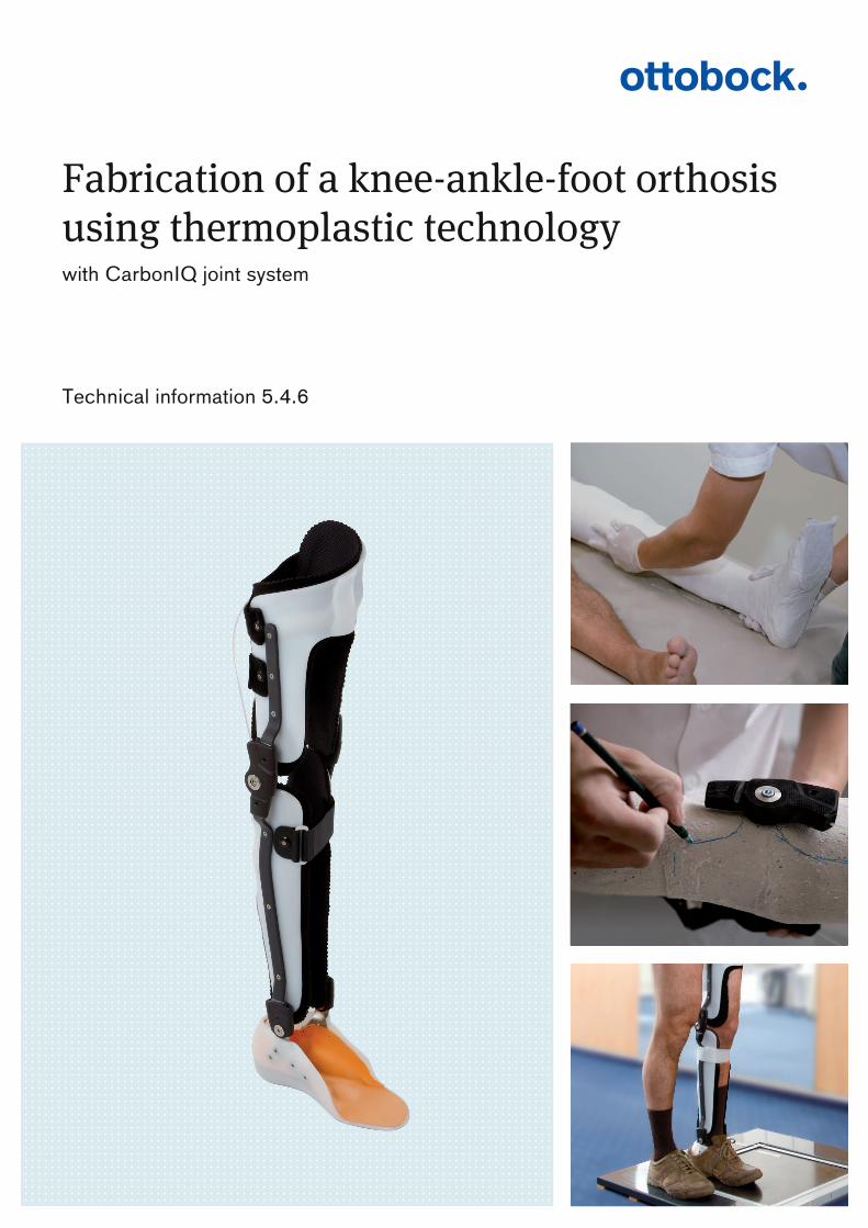
3.1.2 Assembling the System Ankle JointsFollowing the guidelines in the chapter headed "Adaptation Options for the System Ankle Joints" (seePage 26), select a suitable combination for mountingthe cylindrical pins (7, 9), pressure springs (10) andballs (8) to meet the needs of the user.Tighten the setscrews (11). Mount the system ankle joints (1) to the foot stirrups (2).Slide the bearing bushings (3) onto the system anklejoint (1). Secure the foot stirrup (2) with the joint bolt (4), thejoint nut with internal thread (5) and the cap screw (6).Assemble the second system ankle joint in the sameway.
517PA1=* / 17PK1=*
Manufacturing Process

3.2 Fabricating the Plaster Model 3.2.1 Fabricating the Plaster Negative
Apply the markings to the user and enter at least the following user measurements on the measurement form(see Page 28) (observe the bony structures while doingso!):Distance from knee-joint gap to floor
Knee joint width (average between flexed and extendedcondition!)
Distance from ankle-joint centre of rotation to floor
Maximum overall medial and lateral height
6
Manufacturing Process
17PA1=* / 17PK1=*

Width of ankle jointWidth of forefoot under load
Determine the heel height resp. the compensation andthe toe pitch, and then adapt the foot casting aidaccordingly.Apply plaster insulation cream to the foot.
Prepare the plaster negative for the foot.After setting, remove the plaster negative of the footfrom the foot.If necessary, correct the plaster negative of the foot.
Pull a stockinette up over the max. height of the orthosis.To protect the plaster negative when it is to be cutopen, insert corresponding protection into the stockinette from the tip of the foot to above the max. height. Apply the plaster negative foot to the foot.
717PA1=* / 17PK1=*
Manufacturing Process
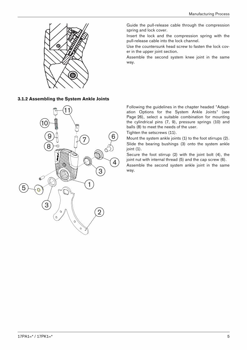
Position the lower leg on the foot casting aid at anangle of 90° to the foot.
Continue applying the plaster cast in the area of thefoot and lower leg (up to a maximum of 10 cm below theknee joint).
Depending on the constitution of the user, placehim/her on an examination table or seat him/her on theedge of the examination table.Move the knee joint into the position defined by theorthosis and then continue with the plaster cast.
If there are any deviations in the knee joint, e.g. valgus/varus deviations, make adjustments by hand.
8
Manufacturing Process
17PA1=* / 17PK1=*

Hold the knee joint in the adjusted position and waituntil the plaster has set.
Mark the cutting line on the plaster. Carefully cut open the plaster negative. Remove the plaster negative.
3.2.2 Fabricating the Plaster PositiveClamp the plaster negative into the alignment apparatus.Using the measurements made, precisely determine thepivot points of the system joints.
917PA1=* / 17PK1=*
Manufacturing Process

Open the plaster negative at the pivot points of the system joints and incorporate the parallel retainers for thesystem knee joint and system ankle joint (ensure thatthe parallel retainers do not get bent!).
Insert a metal rod into the plaster negative.Close and extend the plaster negative.Pour plaster into the plaster negative and allow to set.
3.2.3 Modelling the Foot AreaAfter the plaster negative has set, remove it from theplaster positive.Shorten the parallel retainers.
10
Manufacturing Process
17PA1=* / 17PK1=*

In the joint area, adjust the width to the measurementsthat were made.
Attach the joints to see that they fit.
Design the orthosis according to the specificationsdetermined from the anamnesis and mark correspondingly on the plaster positive.
Shape the heel and forefoot area of the sole parallel toeach other.
1117PA1=* / 17PK1=*
Manufacturing Process

Shape the heel and achilles tendon.
Include a calcaneus brace if desired.
Incorporate the longitudinal arch and midfoot support.
Check the width of the ankle joint compared with themeasured value on the measurement form.
12
Manufacturing Process
17PA1=* / 17PK1=*

Mark and mould the flexion cut-out.
3.2.4 Modelling the Leg AreaShape the edges of the shells.
Smooth the surface.
Check the alignment:• e.g. correct any valgus/varus deviations• Position of the knee joint in AP• Foot position• Dimensions
1317PA1=* / 17PK1=*
Manufacturing Process

3.3 Preparing the Orthosis for Trial Fitting3.3.1 Preparation for Vacuum Forming
Pull a Pedilin pad over the foot area of the plaster positive.
Bend the foot stirrups to match the foot contour.
Screw-fasten the foot stirrups on both sides of the parallel retainer using the joint bushing and the cap screw(see Page 5, Chapter "Assembling the System AnkleJoints" exploded view diagram items 4, 5 and 6). Ifrequired, use spacer washers to increase the gap at theankle joint.Check the shape of the foot stirrups and adjust ifnecessary.
Remove the foot stirrups from the plaster positive.Clamp the plaster positive into the vice.Pull a Perlon stockinette over the plaster positive.
14
Manufacturing Process
17PA1=* / 17PK1=*
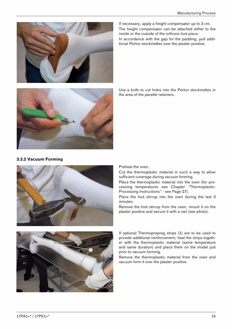
If necessary, apply a height compensator up to 3 cm.The height compensator can be attached either to theinside or the outside of the orthosis foot piece.In accordance with the gap for the padding, pull additional Perlon stockinettes over the plaster positive.
Use a knife to cut holes into the Perlon stockinettes inthe area of the parallel retainers.
3.3.2 Vacuum Forming Preheat the oven. Cut the thermoplastic material in such a way to allowsufficient coverage during vacuum forming. Place the thermoplastic material into the oven (for processing temperatures see Chapter "Thermoplastic:Processing Instructions" - see Page 27).Place the foot stirrup into the oven during the last 3minutes.Remove the foot stirrup from the oven, mount it on theplaster positive and secure it with a nail (see photo).
If optional Thermoprepreg strips (1) are to be used toprovide additional reinforcement, heat the strips together with the thermoplastic material (same temperatureand same duration) and place them on the model justprior to vacuum forming.Remove the thermoplastic material from the oven andvacuum form it over the plaster positive.
1517PA1=* / 17PK1=*
Manufacturing Process

Close the thermoplastic material proximally.Switch on the suction unit to create the vacuum.
Use an arbor tool to press markings for the threadedboreholes of the foot stirrups into the thermoplasticmaterial.
Shorten and press the overlapping thermoplastic material to form an even rim.Allow the thermoplastic material to cool down.
3.3.3 Preparing the Orthosis for Trial FittingUsing the markings in the area of the foot stirrups'boreholes, bore holes (Ø 3.2 mm) into the thermoplastic material.
16
Manufacturing Process
17PA1=* / 17PK1=*

Cut threads (Ø 4 mm) into the foot stirrups' boreholes.
Use M4 countersunk head screws to fasten the foot stirrups to the foot cups.Mark the upper edge of the foot piece and the loweredge of the lower leg shell.
Cut open along the marking (make sure not to damagethe foot stirrups), remove from the form and deflash.
Uncover the joint head of the foot stirrup.
1717PA1=* / 17PK1=*
Manufacturing Process

Also apply a mark for uncovering the parallel retainer onthe knee joint, cut it open and then deflash.
Apply the system knee joints to the trial orthosis.Provisionally apply the system bars.
Set the system bars for the upper and lower leg areascorresponding to the orthosis.Cut to length the system bars for the lower leg areaproviding an excess length of 5 – 10 cm.
After setting, determine the final length of the systembar on the ankle joint and then adapt the system baraccordingly.
18
Manufacturing Process
17PA1=* / 17PK1=*

Rework the fit of the system bars and remove anyridges and burrs.
Check the positioning of the system bars for the lowerleg, making sure that the system ankle joints are seatedparallel within the stop.
Insert the system bar into the system bar receiver andmark the borehole on the system bar.Remove the system bar from the system bar receiverand drill a Ø 4 mm borehole into the system bar.Use the set screw to screw together the system bar andthe system knee joint.The set screw is self-tapping and cuts a correspondingthread into the knee and ankle joints.
Mark, bore and cut to length the system bars for thethigh and screw-fasten them to the system knee joints.
1917PA1=* / 17PK1=*
Manufacturing Process

Check the overall positioning of the system joints andthe system bars.Bore the holes (Ø 4 mm) for fixating the system barsand secure with screws (commence close to the joint).
Cut open the foot piece and the orthosis bushings,remove from the plaster model and finish (grind anddeburr).Remove the orthosis from the plaster positive.Use countersunk screws and locking nuts to screw-fasten the provisional assembly of the system joints,bars, orthosis bushings and the foot piece.Attach the orthosis to the plaster positive and check thealignment.
3.3.4 Trial FittingPerform the first trial fitting on the user.During the first trial fitting, use circularly applied Velcroclosures or straps.Do not permanently fasten the orthosis as yet, becausechanges in position can still be made.
20
Manufacturing Process
17PA1=* / 17PK1=*

Check the fit, safety and function of the alignment.
If available, use a L.A.S.A.R. Posture for determiningthe alignment.
2117PA1=* / 17PK1=*
Manufacturing Process

Perform a standing and walking trial with the user.
3.4 Completion of the Orthosis3.4.1 Adjusting the Orthosis
Only after all fitting and/or alignment problems havebeen resolved can the orthosis be completed.
Attach the closures in the desired position.
22
Manufacturing Process
17PA1=* / 17PK1=*

Cover the system bars with black shrink tubing andheat.
Bond micro-Velcro or similar material into the orthosisfor fastening the pads.Note: To provide a better bonding, first lightlyapply contact adhesive to the plastic and slightlyheat the adhesive surfaces of the Velcro.
Secure the joint bolts and the joint nuts with 636K13Loctite® 241.
For stability reasons, the system bars must be bondedinto the system bar receivers of the system joints using636W28 Ottobock Special Adhesive.Use 634A1 Ottobock thinner and solvent to degreasethe bonding surfaces of the system bars and system barreceivers.Thoroughly mix the contents of the two tubes (specialadhesive and hardener 1:1) and apply the mixture to thecomponents being bonded.Insert the system bars and secure them with the setscrews. The final bonding strength of the adhesive isreached after 16 h.
2317PA1=* / 17PK1=*
Manufacturing Process

If necessary, shorten the pull-release cable of the lockand reinsert it into the lock.
Install the padding.
Before delivering to the user, check the completedorthosis as follows:• Closures properly fastened?• Joints and bars screw-fastened and secured?• Padding installed?• Mounting screws shortened and secured?• Function checked?
24
Manufacturing Process
17PA1=* / 17PK1=*

Conduct a final functional test with the user:(walking, standing, sitting, getting up, other movements)If a L.A.S.A.R. Posture is available, use it and document the final result.Delivery of the finished orthosis.
2517PA1=* / 17PK1=*
Manufacturing Process

4 Appendices4.1 Adaptation Options for the System Ankle JointsDuring assembly, the system ankle joints can be adapted to the needs of the user as follows:
Installation position and effect ApplicationAnterior and posterior: stop pin• Limitation of movement• Adjustable fixed positioning
e.g. ICP or spina bifida
Anterior: spring stop• Support for plantar flexion• Damping and limitation of dorsal
extensionPosterior: stop pin• Limitation of plantar flexion
Indication similar to 2., but withadditionally adjustable dampeddorsal stop
Anterior: stop pin• Limitation of dorsal extensionPosterior: spring stop• Support of dorsal extension• Damping and limitation of plantar
flexion
Dorsiflexion assist, e.g. in case ofpareses of the lower leg muscleswithout muscular knee joint protection
Anterior and posterior: spring stop• Dorsal and plantar support for knee
joint protection• Damping and limitation of plantar
flexion and dorsal flexion, for restricted range of motion
e.g. in case of pareses in thelower leg muscles with weaknessof the knee-protecting muscles
26
Appendices
17PA1=* / 17PK1=*

4.2 Thermoplastic: Processing InstructionsAreas of application: Processing temperatures
(in °C)Product designa
tions (Material) FO DAFO AFO Positioning
orthosis Test
KAFO KAFO Orthosis
strapHeatingplate
Convection oven
Infraredheatingcabinet
ThermoLyn® Trolen616T3(PE-LD)
• • 125
ThermoLyn® PPCopolymer616T120(PP-C)
• • • • 215 185
ThermoLyn® PPHomopolymer616T20(PP-H)
• • • • 215 185
ThermoLyn® Polyethylene 200616T19, 616T58,616T60, 616T61,616T95(PE-HD 200)
• • 180 165
ThermoLyn® RCH500616T22, 616T43,616T44(PE-HD 500)
• • 195 185
ThermoLyn® RCH1000616T16(PE-HD 1000)
• 215 195
ThermoLyn® clear616T83(Copolyester)
• 165
ThermoLyn®Europlex616T70(Polyamide)
• – 135
ThermoLyn® PP-CSilverShield®616T220, 616T221,616T222(Predefined sheetsize - ready to use)(PP-C)
• – 185
SilverShield® is a registered trademark of North Sea Plastics.
2717PA1=* / 17PK1=*
Appendices
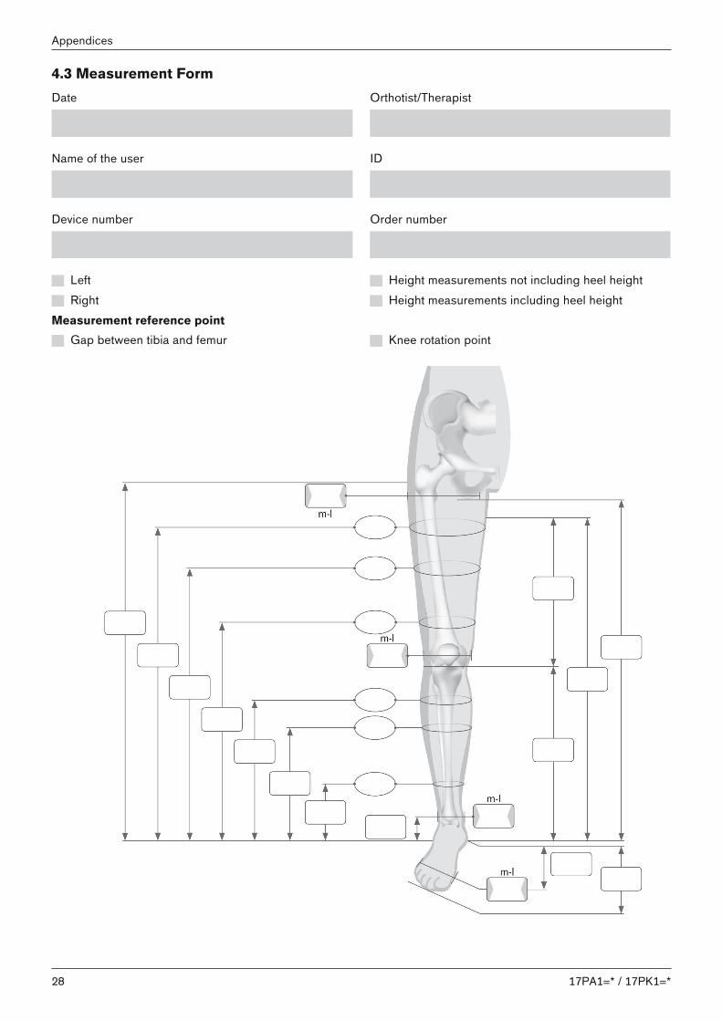
4.3 Measurement FormDate Orthotist/Therapist
Name of the user ID
Device number Order number
Left Height measurements not including heel height Right Height measurements including heel height
Measurement reference pointGap between tibia and femur Knee rotation point
28
Appendices
17PA1=* / 17PK1=*

2917PA1=* / 17PK1=*

17PA1=* / 17PK1=*30

Kundenservice/Customer Service
EuropeOtto Bock HealthCare Deutschland GmbHMax-Näder-Str. 15 · 37115 Duderstadt · GermanyT +49 5527 848-3455 · F +49 5527 [email protected] · www.ottobock.de
Otto Bock Healthcare Products GmbHBrehmstraße 16 · 1110 Wien · AustriaF +43 1 [email protected] · www.ottobock.at
Otto Bock Adria d.o.o. SarajevoRamiza Salčina 8571000 Sarajevo · Bosnia-HerzegovinaT +387 33 255-405 · F +387 33 [email protected] · www.ottobockadria.com.ba
Otto Bock Bulgaria Ltd.41 Tzar Boris III‘ Blvd. · 1612 Sofia · BulgariaT +359 2 80 57 980 · F +359 2 80 57 [email protected] · www.ottobock.bg
Otto Bock Suisse AGLuzerner Kantonsspital 10 · 6000 Luzern 16 · SuisseT +41 41 455 61 71 · F +41 41 455 61 [email protected] · www.ottobock.ch
Otto Bock ČR s.r.o.Protetická 460 · 33008 Zruč-Senec · Czech RepublicT +420 377825044 · F +420 [email protected] · www.ottobock.cz
Otto Bock Iberica S.A.C/Majada, 1 · 28760 Tres Cantos (Madrid) · SpainT +34 91 8063000 · F +34 91 [email protected] · www.ottobock.es
Otto Bock France SNC4 rue de la Réunion - CS 9001191978 Courtaboeuf Cedex · FranceT +33 1 69188830 · F +33 1 [email protected] · www.ottobock.fr
Otto Bock Healthcare plc32, Parsonage Road · Englefield GreenEgham, Surrey TW20 0LD · United KingdomT +44 1784 744900 · F +44 1784 [email protected] · www.ottobock.co.uk
Otto Bock Hungária Kft.Tatai út 74. · 1135 Budapest · HungaryT +36 1 4511020 · F +36 1 [email protected] · www.ottobock.hu
Otto Bock Adria d.o.o.Dr. Franje Tuđmana 14 ·10431 Sveta Nedelja · CroatiaT +385 1 3361 544 · F +385 1 3365 [email protected] · www.ottobock.hr
Otto Bock Italia Srl UsVia Filippo Turati 5/7 · 40054 Budrio (BO) · ItalyT +39 051 692-4711 · F +39 051 [email protected] · www.ottobock.it
Otto Bock Benelux B.V.Mandenmaker 14 · 5253 RCNieuwkuijk · The NetherlandsT +31 73 5186488 · F +31 73 [email protected] · www.ottobock.nl
Industria Ortopédica Otto Bock Unip. Lda.Av. Miguel Bombarda, 21 - 2º Esq.1050-161 Lisboa · PortugalT +351 21 3535587 · F +351 21 [email protected]
Otto Bock Polska Sp. z o. o.Ulica Koralowa 3 · 61-029 Poznań · PolandT +48 61 6538250 · F +48 61 [email protected] · www.ottobock.pl
Otto Bock Romania srlŞos de Centura Chitila - Mogoşoaia Nr. 3077405 Chitila, Jud. Ilfov · RomaniaT +40 21 4363110 · F +40 21 [email protected] · www.ottobock.ro
OOO Otto Bock Servicep/o Pultikovo, Business Park „Greenwood“,Building 7, 69 km MKAD143441 Moscow Region/Krasnogorskiy RayonRussian FederationT +7 495 564 8360 · F +7 495 564 [email protected] · www.ottobock.ru
Otto Bock Scandinavia ABKoppargatan 3 · Box 623 · 60114 Norrköping · SwedenT +46 11 280600 · F +46 11 [email protected] · www.ottobock.se
Otto Bock Slovakia s.r.o.Röntgenova 26 · 851 01 Bratislava 5 · Slovak RepublicT +421 2 32 78 20 70 · F +421 2 32 78 20 [email protected] · www.ottobock.sk
Otto Bock Sava d.o.o.Industrijska bb · 34000 Kragujevac · Republika SrbijaT +381 34 351 671 · F +381 34 351 [email protected] · www.ottobock.rs
Otto Bock Ortopedi ve Rehabilitasyon Tekniği Ltd. Şti.Mecidiyeköy Mah. Lati Lokum Sok.Meriç Sitesi B Blok No: 30/B34387 Mecidiyeköy-İstanbul · TurkeyT +90 212 3565040 · F +90 212 [email protected] · www.ottobock.com.tr
AfricaOtto Bock Algérie E.U.R.L.32, rue Ahcène Outaleb - Coopérative les MimosasMackle-Ben Aknoun · Alger · DZ AlgérieT +213 21 913863 · F +213 21 [email protected] · www.ottobock.fr
Otto Bock Egypt S.A.E.28 Soliman Abaza St. Mohandessein - Giza · EgyptT +20 2 37606818 · F +20 2 [email protected] · www.ottobock.com.eg
Otto Bock South Africa (Pty) LtdBuilding 3 Thornhill Office Park · 94 Bekker RoadMidrand · Johannesburg · South AfricaT +27 11 564 [email protected]
AmericasOtto Bock Argentina S.A.Av. Belgrano 1477 · CP 1093Ciudad Autônoma de Buenos Aires · ArgentinaT +54 11 5032-8201 / [email protected]
Otto Bock do Brasil Tecnica Ortopédica Ltda.Alameda Maria Tereza, 4036, Bairro Dois CórregosCEP: 13.278-181, Valinhos-São Paulo · Brasil T +55 19 3729 3500 · F +55 19 3269 6061 [email protected] · www.ottobock.com.br
Otto Bock HealthCare Canada5470 Harvester Road Burlington, Ontario, L7L 5N5, CanadaT +1 800 665 3327 · F +1 800 463 [email protected] ·www.ottobock.ca
Oficina Ottobock HabanaCalle 3ra entre 78 y 80.Edificio Jerusalen · Oficina 112 · Calle 3ra.Playa, La Habana. CubaT +53 720 430 69 · +53 720 430 [email protected]
Otto Bock HealthCare Andina Ltda.Calle 138 No 53-38 · Bogotá · ColombiaT +57 1 8619988 · F +57 1 [email protected] · www.ottobock.com.co
Otto Bock de Mexico S.A. de C.V.Prolongación Calle 18 No. 178-ACol. San Pedro de los PinosC.P. 01180 México, D.F. · MexicoT +52 55 5575 0290 · F +52 55 5575 [email protected] · www.ottobock.com.mx
Otto Bock HealthCare LP11501 Alterra Parkway Suite 600Austin, TX 78758 · USAT +1 800 328 4058 · F +1 800 962 [email protected]
Asia/PacificOtto Bock Australia Pty. Ltd.Suite 1.01, Century Corporate Centre62 Norwest BoulevardeBaulkham Hills NSW 2153 · AustraliaT +61 2 8818 2800 · F +61 2 8814 [email protected] · www.ottobock.com.au
Beijing Otto Bock Orthopaedic Industries Co., Ltd.B12E, Universal Business Park10 Jiuxianqiao Road, Chao Yang DistrictBeijing, 100015, P.R. ChinaT +8610 8598 6880 · F +8610 8598 [email protected]
Otto Bock Asia Pacific Ltd.Unit 1004, 10/F, Greenfield Tower, Concordia Plaza 1 Science Museum Road, Tsim Sha TsuiKowloon, Hong Kong · China T +852 2598 9772 · F +852 2598 7886 [email protected] · www.ottobock.com
Otto Bock HealthCare India Pvt. Ltd.20th Floor, Express TowersNariman Point, Mumbai 400 021 · IndiaT +91 22 2274 5500 / 5501 / [email protected] · www.ottobock.in
Otto Bock Japan K. K.Yokogawa Building 8F, 4-4-44 ShibauraMinato-ku, Tokyo, 108-0023 · JapanT +81 3 3798-2111 · F +81 3 [email protected] · www.ottobock.co.jp
Otto Bock Korea HealthCare Inc.4F Agaworld Building · 1357-74, Seocho-dongSeocho-ku, 137-070 Seoul · KoreaT +82 2 577-3831 · F +82 2 [email protected] · www.ottobockkorea.com
Otto Bock South East Asia Co., Ltd.1741 Phaholyothin RoadKwaeng Chatuchark · Khet ChatucharkBangkok 10900 · ThailandT +66 2 930 3030 · F +66 2 930 [email protected] · www.ottobock.co.th

Template-Version: SB_2016-10-21 · FM483 · SB_210x297
Otto Bock HealthCare GmbHMax-Näder-Straße 15 · 37115 Duderstadt · Germany T +49 5527 848-0 · F +49 5527 72330 [email protected] · www.ottobock.com
© O
ttobo
ck ·
646T
546=
en-0
6-17
06
Printed by: