Fabrication Design Progress of ITER Vacuum Vessel in Korea
8
1 ITR/P1-42 Fabrication Design Progress of ITER Vacuum Vessel in Korea B. C. Kim, J. W. Sa, H. S Kim, Y. J. Lee, K. H. Hong, H. J. Ahn, J. S. Bak, K. J. Jung ITER Korea, National Fusion Research Institute, Daejeon, Republic of Korea K. H. Park, T. S. Kim, J. S. Lee, H. J. Sung, Y. K. Kim, T. H. Kwon, J. K. Ham, Y. S. Hong, S. B. Shin, H. G. Kim, D. J. Lee, I. K. Kwon, H. K. Jin, D. S. Kim Hyundai Heavy Industries Co. Ltd., Ulsan, Republic of Korea E-mail contact of main author: [email protected] Abstract. Korea, as the in kind provider of the two ITER vacuum vessel (VV) main vessel sectors, equatorial and lower ports structures, made the first procurement arrangement (PA) on the VV. After the contract with Hyundai Heavy Industry (HHI) for the VV fabrication, HHI with KODA did some R&D to develop the fabrication procedures. The mock up to optimize the electron beam welding techniques will be fabricated. In parallel, the fabrication design is also ongoing with special attention on the control of welding deformation. To meet the special requirement on the material, supporting R&D with the KO’s mill maker was also done. 1. Introduction Korea has responsibility for the procurement of two ITER VV main vessel sectors: equatorial and lower ports structures, including the vacuum vessel supports and the neutral beam liner. After signing the PA with the ITER Organization in November 2008, KODA proceeded to contract with industry for the fabrication of two sectors, the equatorial and lower ports structures. KODA made a contract with HHI in January 2010. IO provided KODA with the VV design that is preliminary approved by the agreed notified body (ANB). This paper reports the fabrication design progress done by KODA and HHI based on the IO VV design. In addition, the pilot ITER grade material development results with Korean mill makers are introduced. 2. Design Progress 2.1 R&D mock-up design and fabrication With the purpose to establish manufacturing method, there were several full scale mock-ups [1, 2] for the ITER VV. HHI also decide to make a partial full scale mock-up to develop their fabrication procedures. The first mock-up is to develop and stabilize the electron beam welding techniques. The lower parts of the inboard segment were made to optimize the electron beam welding (EBW) techniques, including repair and non-destructive examination (NDE) method development. The second mock-up is 20 degree upper segment. This will verify the forming, machining techniques, welding sequence optimization and distortion control. By this mock-up, HHI will also ensure that the NG-GTAW welding method, NDE procedures, and dimension inspection method are applicable for final production. In addition, a 10 degree partial mock-up for the triangular support of lower segment is planned to develop the copper cladding fabrication method. The detail features of the mock-ups under development are shown in Fig. 1. The first step of mock-up fabrication was the EBW test with the specimen to find the optimum welding parameters. After surveying the welding parameter by bead on plate welding, the liner butt joint and circular welding tests are performed. Fig. 2 shows the radiographic test of result for the liner butt joint welding specimen. Both sides of the EBW shows the optimum results and
Transcript of Fabrication Design Progress of ITER Vacuum Vessel in Korea

1 ITR/P1-42
Fabrication Design Progress of ITER Vacuum Vessel in Korea
B. C. Kim, J. W. Sa, H. S Kim, Y. J. Lee, K. H. Hong, H. J. Ahn, J. S. Bak, K. J. Jung
ITER Korea, National Fusion Research Institute, Daejeon, Republic of Korea
K. H. Park, T. S. Kim, J. S. Lee, H. J. Sung, Y. K. Kim, T. H. Kwon, J. K. Ham, Y. S. Hong,
S. B. Shin, H. G. Kim, D. J. Lee, I. K. Kwon, H. K. Jin, D. S. Kim
Hyundai Heavy Industries Co. Ltd., Ulsan, Republic of Korea
E-mail contact of main author: [email protected]
Abstract. Korea, as the in kind provider of the two ITER vacuum vessel (VV) main vessel sectors, equatorial
and lower ports structures, made the first procurement arrangement (PA) on the VV. After the contract with
Hyundai Heavy Industry (HHI) for the VV fabrication, HHI with KODA did some R&D to develop the
fabrication procedures. The mock up to optimize the electron beam welding techniques will be fabricated. In
parallel, the fabrication design is also ongoing with special attention on the control of welding deformation. To
meet the special requirement on the material, supporting R&D with the KO’s mill maker was also done.
1. Introduction
Korea has responsibility for the procurement of two ITER VV main vessel sectors: equatorial
and lower ports structures, including the vacuum vessel supports and the neutral beam liner.
After signing the PA with the ITER Organization in November 2008, KODA proceeded to
contract with industry for the fabrication of two sectors, the equatorial and lower ports
structures. KODA made a contract with HHI in January 2010. IO provided KODA with the
VV design that is preliminary approved by the agreed notified body (ANB). This paper reports
the fabrication design progress done by KODA and HHI based on the IO VV design. In
addition, the pilot ITER grade material development results with Korean mill makers are
introduced.
2. Design Progress
2.1 R&D mock-up design and fabrication
With the purpose to establish manufacturing method, there were several full scale mock-ups
[1, 2] for the ITER VV. HHI also decide to make a partial full scale mock-up to develop their
fabrication procedures. The first mock-up is to develop and stabilize the electron beam
welding techniques. The lower parts of the inboard segment were made to optimize the
electron beam welding (EBW) techniques, including repair and non-destructive examination
(NDE) method development. The second mock-up is 20 degree upper segment. This will
verify the forming, machining techniques, welding sequence optimization and distortion
control. By this mock-up, HHI will also ensure that the NG-GTAW welding method, NDE
procedures, and dimension inspection method are applicable for final production. In addition,
a 10 degree partial mock-up for the triangular support of lower segment is planned to develop
the copper cladding fabrication method.
The detail features of the mock-ups under development are shown in Fig. 1. The first step of
mock-up fabrication was the EBW test with the specimen to find the optimum welding
parameters. After surveying the welding parameter by bead on plate welding, the liner butt
joint and circular welding tests are performed. Fig. 2 shows the radiographic test of result for
the liner butt joint welding specimen. Both sides of the EBW shows the optimum results and

2 ITR/P1-42
this will be selected as a basic welding scheme.
FIG. 1. The detail features of mock-up
FIG. 2. RT result of linear butt joint EBW
The components of each mock-up are under fabrication. The bending of inner and outer shell
of the vacuum vessel inboard segment mock-up is finished and the machining of the centering
key and flexible support housing is ongoing. For the vacuum vessel upper segment mock-up,
the design of forming jig is finished and the fabrication of jigs is in progress.
2.2 Fabrication design of main vessel
The design thickness of inner and outer shell of main vessel sector is 60 mm. The rough
estimation of plate thickness reduction during forming process is about 5 - 9 %. To evaluate
the influences of the shell thickness reduction due to forming on the structural integrity of the
main vessel, the finite element model provided by IO has been modified. The overall shell
thickness of the main vessel in the finite element model has been changed from 60 mm to 54
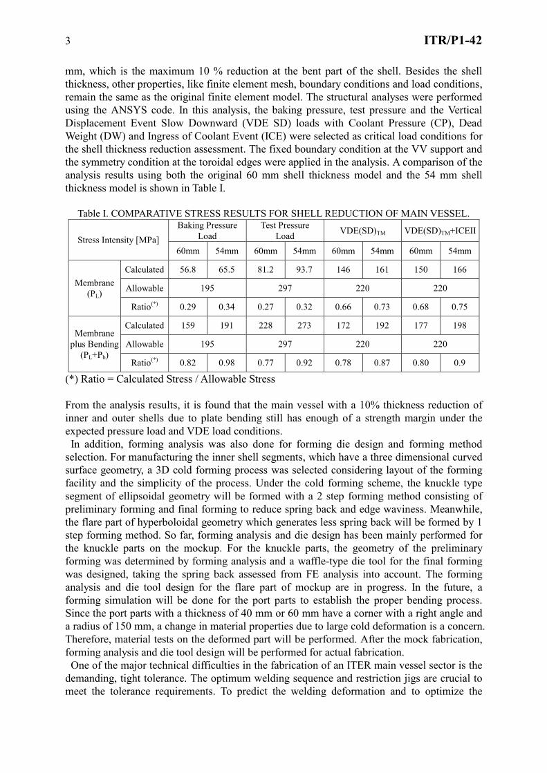
3 ITR/P1-42
mm, which is the maximum 10 % reduction at the bent part of the shell. Besides the shell
thickness, other properties, like finite element mesh, boundary conditions and load conditions,
remain the same as the original finite element model. The structural analyses were performed
using the ANSYS code. In this analysis, the baking pressure, test pressure and the Vertical
Displacement Event Slow Downward (VDE SD) loads with Coolant Pressure (CP), Dead
Weight (DW) and Ingress of Coolant Event (ICE) were selected as critical load conditions for
the shell thickness reduction assessment. The fixed boundary condition at the VV support and
the symmetry condition at the toroidal edges were applied in the analysis. A comparison of the
analysis results using both the original 60 mm shell thickness model and the 54 mm shell
thickness model is shown in Table I.
Table I. COMPARATIVE STRESS RESULTS FOR SHELL REDUCTION OF MAIN VESSEL.
Stress Intensity [MPa]
Baking Pressure
Load
Test Pressure
Load VDE(SD)TM VDE(SD)TM+ICEII
60mm 54mm 60mm 54mm 60mm 54mm 60mm 54mm
Membrane
(PL)
Calculated 56.8 65.5 81.2 93.7 146 161 150 166
Allowable 195 297 220 220
Ratio(*)
0.29 0.34 0.27 0.32 0.66 0.73 0.68 0.75
Membrane
plus Bending
(PL+Pb)
Calculated 159 191 228 273 172 192 177 198
Allowable 195 297 220 220
Ratio(*)
0.82 0.98 0.77 0.92 0.78 0.87 0.80 0.9
(*) Ratio = Calculated Stress / Allowable Stress
From the analysis results, it is found that the main vessel with a 10% thickness reduction of
inner and outer shells due to plate bending still has enough of a strength margin under the
expected pressure load and VDE load conditions.
In addition, forming analysis was also done for forming die design and forming method
selection. For manufacturing the inner shell segments, which have a three dimensional curved
surface geometry, a 3D cold forming process was selected considering layout of the forming
facility and the simplicity of the process. Under the cold forming scheme, the knuckle type
segment of ellipsoidal geometry will be formed with a 2 step forming method consisting of
preliminary forming and final forming to reduce spring back and edge waviness. Meanwhile,
the flare part of hyperboloidal geometry which generates less spring back will be formed by 1
step forming method. So far, forming analysis and die design has been mainly performed for
the knuckle parts on the mockup. For the knuckle parts, the geometry of the preliminary
forming was determined by forming analysis and a waffle-type die tool for the final forming
was designed, taking the spring back assessed from FE analysis into account. The forming
analysis and die tool design for the flare part of mockup are in progress. In the future, a
forming simulation will be done for the port parts to establish the proper bending process.
Since the port parts with a thickness of 40 mm or 60 mm have a corner with a right angle and
a radius of 150 mm, a change in material properties due to large cold deformation is a concern.
Therefore, material tests on the deformed part will be performed. After the mock fabrication,
forming analysis and die tool design will be performed for actual fabrication.
One of the major technical difficulties in the fabrication of an ITER main vessel sector is the
demanding, tight tolerance. The optimum welding sequence and restriction jigs are crucial to
meet the tolerance requirements. To predict the welding deformation and to optimize the

4 ITR/P1-42
welding sequence, the welding distortion of vacuum vessel in each fabrication process is
evaluated and the principal distortion factor is identified. Based on the results, the proper
control methods for excessive distortion will be proposed. The upper segment of 40o part was
selected to establish the distortion control method for the ITER VV. In order to evaluate the
welding distortion on the upper segment in each manufacturing process, the characteristic of
simple weldment such as angular distortion, transverse shrinkage and longitudinal shrinkage
force was evaluated by the conventional FEA methods, which are heat transfer and thermo
mechanical stress analysis. Then the welding distortion of the actual VV was evaluated using
by STEM (simplified thermo elastic method). [3] In STEM, the welding distortion at the
actual structure is evaluated directly by implanting the inherent strain of simple weldment to
the actual weldment. From the evaluation results of welding distortion for upper segment, the
principal distortion factor was identified as angular distortion and transverse shrinkage, which
are the cause of the excessive out-of plane distortion in the VV. Through these evaluation
procedures, the restraint reinforcing method was selected as a countermeasure to control the
out-of plane distortion of the ITER VV.
(a) Upper segment with reinforcing restraint stiffener
0o
160o
R
θ
Φ
R
θ
Φ
0o
160o
R
θ
Φ
R
θ
Φ
0.0 45.0 90.0 135.0 180.0
theta, (o)
0.0
50.0
100.0
150.0
200.0
250.0
Rad
ial
Dis
tort
ion
(m
m)
Before distortion control
After distortion control
Allowable Limit : 15mm
(b) Without restraint stiffener (c) With restraint stiffener (d) Radial distortion
FIG. 3. Contours of welding distortion at the upper segment with and without restraint method and
radial distortion of θ direction in the inner shell plate of the upper segment (unit: mm)
Figure 3(a) shows the configuration of the upper segment with a restraint stiffener to control
excessive welding distortion. In reference, the arrangement and size of restraint fixture was
designed with consideration of bending restraint of weldment. Figure 3(b) and (c) shows the
contours of the welding distortion at the upper segment in the final welding stage with the
restraint method. As shown in Figure 3(b) and (c), after the restraint method was applied, the
amount of maximum welding distortion at the upper segment was reduced from 189 mm to
111 mm. Figure 3(d) shows the distribution of radial distortion in the inner shell plate of the
upper segment with and without the restraint fixture. As shown in Figure 3(d), with the
restraint applied, the welding distortion in the radial direction of inner shell plate sharply
deceases by about 30%. However, the maximum radial distortion exceeded the allowable
value of ±15 mm in the main vessel sector. This is attributed to the fact that the restraint
reinforcing method with the temporary fixture could not properly control the out-of plane

5 ITR/P1-42
distortion of the upper segment caused by transverse shrinkage, unlike angular distortion and
longitudinal shrinkage force [4]. Based on the results, using the restraint method with a
temporary fixture could be considered as the countermeasure against the out-of plane
distortion of upper segment. However, this method is not a panacea for all distortion problems
of the upper segment for the main vessel sector. Therefore, it can be concluded that the
application of proper method, such as the tensioning method, should be considered in the
future to satisfy the dimensional accuracy of upper segment by reducing the transverse
shrinkage effect on the out-of plane distortion of upper segment.
The ITER vacuum vessel is made with thick stainless steel, 316L(N)-IG and 304L. The
shape of the VV and ports are a very complicated double wall structure and required severe
dimension control. Based on these considerations, narrow gap GTAW and EBW procedures
were considered as the main welding processes. GTAW processes are divided into a manual
type and a machine type in terms of their accessibility and productivity. Most welding joints
are the narrow gap type in order to minimize welding distortion and to increase productivity.
Three different welding equipments are under development by HHI for the fabrication
sequences. They are main shell butt welding, reinforcement rib to main shell welding and
shell to housing with narrow gap joint and hot wire system. To satisfy the dimension control
specification, EBW process for the inboard segment is under development under a full
vacuum system. In general, EBW is used with a steel backing material in order to prevent it
from melting through under a flat position. To minimize after-treatment, several welding tests
will be performed to determine whether the steel backing material can be removed or not. Two
types of welding consumables are considered to apply manual GTAW and machine GTAW.
The NDE work conforms to the RCC-MR 2007 code for class 2 box structures. Section 3,
related to examination methods, also refers to European and ISO Standards. A combination
examination, such as visual examination, surface and volumetric NDE defined in the RCC-
MR Table RS 7720 will be performed. Radiographic examination is the reference method for
volumetric examination of welds. If it is not possible, radiographic examination (e.g., if there
is no access to the back side of the welds) will be performed and welds requiring volumetric
examination shall be inspected by ultrasonic examination. The ultrasonic examination shall be
done with a combination of the Phased-Array and Pulse-Echo manual ultrasonic techniques.
Ultrasonic examination of full penetration austenitic stainless steel welds is not covered in the
RCC-MR 2007 and a procedure will be established and qualified. All NDE shall be performed
by Level-2 or 3 qualified and certified personnel as per NF EN 473. All NDE procedures and
reports shall be approved by Level-3 personnel.
Besides these activities, the 3D multipart and 2D drawings are prepared and the dedicated
fabrication procedures are developed to acquire the approval from the IO and ANB.
2.3 Fabrication design of equatorial and lower ports
The fabrication design items made by HHI are 14 regular equatorial ports, 3 neutral beam
ports and 9 lower ports with several local penetrations. The detail design of the in-wall shield
in the neutral beam port is also carried out through a task agreement with IO. The design
activities for ports are similar with those of main vessel. The fabrication feasibility study for
ports is also done and some practical proposal to simplify the fabrication process will be made.
The small R&D mock-up is fabricated to check the thickness reduction by the sharp bending
in the corner area of the port structures. Similar to the main vessel, the port structures will also
experience bending and forming during fabrication, which inevitably produces a thickness
reduction of the shell in the bent region. To evaluate the shell thickness reduction effects on
structural integrity of the port structure, the previously developed finite element model has

6 ITR/P1-42
been modified by assuming that a maximum 16.7% thickness reduction occurs at the bent
region of the ports. Unlike the main vessel, there are many different port structures in the
ITER vacuum vessel and many different types of bending regions. As an initial approach, a
lower port stub extension model was selected for the typical shell thickness reduction model
due to forming. The structural analyses were performed adjusting the thickness of inner and
outer shell of the lower port stub extension (60 mm, 54 mm and 50 mm) while the shell
thickness of the main vessel is held fixed to 54 mm. Besides the shell thickness, other
properties remain the same as the original finite element model. These structural analyses
were also performed using the ANSYS code, and all the load cases and boundary conditions
are the same as those of the shell thickness reduction analysis done for the main vessel. In the
typical maximum VDE condition and VDE with ICEII condition, the analyses results for the
thickness reduction effect of the lower port are summarized in Table II.
Table II. STRESS FOR LOWER PORT STUB EXTENSION UNDER VDE LOADS.
Stress Intensity [MPa] VDE(SD)TM VDE(SD)TM + ICEII
60mm 54mm 50mm 60mm 54mm 50mm
Inner
and
Outer
Shell
PL
Calculated 128 145 159 129 146 160
Allowable 220 220
Ratio(*)
0.58 0.66 0.72 0.59 0.66 0.73
PL+Pb
Calculated 160 167 182 160 167 183
Allowable 220 220
Ratio(*)
0.73 0.76 0.83 0.73 0.76 0.83
Rib
PL
Calculated 126 128 130 126 129 130
Allowable 220 220
Ratio(*)
0.57 0.58 0.59 0.57 0.59 0.59
PL+Pb
Calculated 195 199 201 196 200 202
Allowable 220 220
Ratio(*)
0.89 0.91 0.91 0.89 0.91 0.92
(*) Ratio = Calculated Stress / Allowable Stress
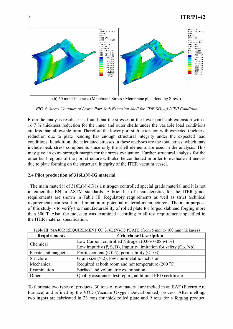
Figure 4 shows the stress contours of the lower port stub extension shell under a VDE(SD)TM
+ ICEII condition. All calculated stresses are within the allowable limit.
(a) 60 mm Thickness (Membrane Stress / Membrane plus Bending Stress)
7 ITR/P1-42
(b) 50 mm Thickness (Membrane Stress / Membrane plus Bending Stress)
FIG. 4. Stress Contours of Lower Port Stub Extension Shell for VDE(SD)TM+ICEII Condition
From the analysis results, it is found that the stresses at the lower port stub extension with a
16.7 % thickness reduction for the inner and outer shells under the variable load conditions
are less than allowable limit Therefore the lower port stub extension with expected thickness
reduction due to plate bending has enough structural integrity under the expected load
conditions. In addition, the calculated stresses in these analyses are the total stress, which may
include peak stress components since only the shell elements are used in the analysis. This
may give an extra strength margin for the stress evaluation. Further structural analysis for the
other bent regions of the port structure will also be conducted in order to evaluate influences
due to plate forming on the structural integrity of the ITER vacuum vessel.
2.4 Pilot production of 316L(N)-IG material
The main material of 316L(N)-IG is a nitrogen controlled special grade material and it is not
in either the EN or ASTM standards. A brief list of characteristics for the ITER grade
requirements are shown in Table III. Regulatory requirements as well as strict technical
requirements can result in a limitation of potential material manufacturers. The main purpose
of this study is to verify the manufacturability of rolled plate for forged slab and forging more
than 300 T. Also, the mock-up was examined according to all test requirements specified in
the ITER material specification.
Table III: MAJOR REQUIREMENT OF 316L(N)-IG PLATE (from 5 mm to 100 mm thickness)
Requirements Criteria or Description
Chemical Low Carbon, controlled Nitrogen (0.06~0.08 wt.%)
Low impurity (P, S, B), Impurity limitation for safety (Co, Nb)
Ferrite and magnetic Ferrite content (< 0.5), permeability (<1.03)
Structure Grain size (> 2), low non-metallic inclusion
Mechanical Required at both room and hot temperature (200 oC)
Examination Surface and volumetric examination
Others Quality assurance, test report, additional PED certificate
To fabricate two types of products, 30 tons of raw material are melted in an EAF (Electro Arc
Furnace) and refined by the VOD (Vacuum Oxygen De-carbonized) process. After melting,
two ingots are fabricated in 23 tons for thick rolled plate and 9 tons for a forging product.

8 ITR/P1-42
Fabrication processes after melting are forging, heat treatment, and test/inspection. The
product size is 368x470x5420 mm (thickness x width x length) before surface machining. The
main fabrication processes for thick rolled plate of 120T are a forging, surface machining,
heating and rolling, heat treatment, and test/inspection. This forged slab of 333x1620x3590
mm before rolling was cut and machined by 10 tons to fit into the heat treatment facility. In
the heat treatment process, temperature sensors are embedded in the center of forged slab to
monitor temperature deviation. Table IV shows the ladle analysis results, but a few contents
(Nb, Ta, Ti) are not shown. The ITER VV material also requires product analysis (not shown
here). Mechanical test results for the forged product are summarized in Table V. Results at
both room temperature and 200o
C satisfy criteria required in the VV material specification.
Other requirements, such as grain size, ferrite content, permeability, have been verified.
TABLE IV: CHEMICAL COMPOSITION FOR LADLE ANALYSIS
C Mn Si P S Cr Ni Mo N B Cu Co
Min. 1.60 17.00 12.00 2.30 0.060
Max. 0.030 2.00 0.50 0.025 0.010 18.00 12.50 2.70 0.080 0.001 0.30 0.050
Results 0.025 1.82 0.24 0.015 0.002 17.42 12.22 2.48 0.069 0.0005 0.039 0.030
TABLE V: MECHANICAL TEST RESULTS
Room temperature Hot temperature (200 oC)
MPa Yield Tensile EL(%) R.A(%) Yield Tensile EL(%) R.A(%)
Criteria 220 525~700 45 % N/A 144 423 N/A N/A
Results 277 537 57 79 182 446 52 79
3. Summary
The full scale fabrication of the R&D mock-ups is ongoing by HHI. This will instill
confidence in the manufacturing procedures of the ITER VV. The results of R&D will be fully
incorporated in the final manufacturing process. The quality, manufacturing and inspection
plans are prepared and the fabrication drawing and procedures are also under preparation and
are awaiting approval from IO and ANB before the start of manufacturing. To deliver the first
assembled sector (#6 sector) in the ITER site on time, real fabrication is scheduled to start in
early 2011.
The views and opinions expressed herein do not necessarily reflect those of the ITER
Organization.
References
[1] L. Jones, et al., Fusion Engineering and Design 82, 1942 (2007).
[2] M. Nakahira, et al., Fusion Engineering and Design 83, 1578 (2008).
[3] Y K, Park, et al., “A study on the Welding Deformation of Ship Structure using Simplified
Thermo-elastic Analysis”, Proceeding of 2001 Spring Annual Meeting of KWS, pp. 274-
276(2001).
[4] S. B. Shin, et al., “Effects of Internal and External Restraint on Welding Distortion”,
Proceeding of 2001 Spring Annual Meeting of KWS, pp.165-168(2001)