Fabrication and characterization of a flow-through ... · Nanotechnology 19 (2008) 335604 LLiuet al...
6
IOP PUBLISHING NANOTECHNOLOGY Nanotechnology 19 (2008) 335604 (6pp) doi:10.1088/0957-4484/19/33/335604 Fabrication and characterization of a flow-through nanoporous gold nanowire/AAO composite membrane L Liu 1 , W Lee 1,2 , Z Huang 1 , R Scholz 1 and U G ¨ osele 1 1 Max Planck Institute of Microstructure Physics, Weinberg 2, D-06120 Halle, Germany 2 Korea Research Institute of Standards and Science, Yuseong, 305-340 Daejon, Korea E-mail: [email protected] and [email protected] Received 13 April 2008, in final form 5 June 2008 Published 7 July 2008 Online at stacks.iop.org/Nano/19/335604 Abstract The fabrication of a composite membrane of nanoporous gold nanowires and anodic aluminum oxide (AAO) is demonstrated by the electrodeposition of Au–Ag alloy nanowires into an AAO membrane, followed by selective etching of silver from the alloy nanowires. This composite membrane is advantageous for flow-through type catalytic reactions. The morphology evolution of the nanoporous gold nanowires as a function of the diameter of the Au–Ag nanowire ‘precursors’ is also investigated. S Supplementary data are available from stacks.iop.org/Nano/19/335604 (Some figures in this article are in colour only in the electronic version) 1. Introduction Nanoporous gold (NPG) foams have attracted considerable technological interest due to their wide range of applications in catalysis [1–6], sensing [7, 8], actuators [9, 10], electro- chemical capacitors [11], surface-enhanced Raman scattering (SERS) [12, 13], low-temperature heat exchangers [14], etc. The NPG structures are usually produced by selective chemi- cal or electrochemical dissolution of Au–Ag alloys, known as a ‘dealloying’ process in the context of corrosion technology. In terms of catalytic applications, NPG foams have at least two advantages over other catalysts or gold nanoparticles. Firstly, unlike platinum or palladium catalysts, NPG remains active at low temperature (room temperature or even lower), which is desirable for many practical applications [3, 4]. Secondly, NPG has a good thermal stability and is resistant to oxidation [3, 15], and thus can overcome the aggregation or sintering limitations from which gold nanoparticles often suffer upon the elevation of temperature or in an oxidative environment [16]. Although NPG foams have been demonstrated to show high CO oxidation activity, the catalytic reactions only occur at the surfaces of the NPG foams [3]. As a result, the high specific surface area of NPG foams can often not be utilized efficiently. Ultrathin NPG films (about 100 nm) made by dealloying white-gold leaves may overcome this limitation to a certain extent, but these ultrathin films are very fragile and exhibit brittle fracture [2, 4], which makes it difficult to find practical applications in flow-through type catalysis. Recently, Dotzauer et al reported the fabrication of catalytic membranes composed of gold nanoparticles immobilized in a porous anodic aluminum oxide (AAO) [17]. The porous membrane configuration allows flow-through catalytic reactions, and the flow (e.g. gas or liquid) through the porous membrane gives rise to a rapid convective mass transport of the reactant to the immobilized catalysts. In this case, conversions often depend on kinetics or mass flow, rather than diffusion. Therefore, flow-through type membrane supported catalysts can overcome the diffusion limitation that usually occurs in fluidized bed reactors or homogeneous solutions of catalytic beads [18]. Other groups have also pointed out the importance of mass transport on the catalytic activity when using NPG films as catalysts [3]. Here, we present a novel composite catalytic membrane which consists of an NPG nanowire (NW) array immobilized in an AAO membrane (i.e., an NPG NW/AAO composite membrane). Previously, NPG nanowires were also synthesized via a template-based approach [6, 8, 15, 19, 20], but the alumina template was usually removed before the dealloying process, thus leaving dispersed NPG nanowires, while in our case, the AAO membrane can still be retained without any 0957-4484/08/335604+06$30.00 © 2008 IOP Publishing Ltd Printed in the UK 1
Transcript of Fabrication and characterization of a flow-through ... · Nanotechnology 19 (2008) 335604 LLiuet al...
IOP PUBLISHING NANOTECHNOLOGY
Nanotechnology 19 (2008) 335604 (6pp) doi:10.1088/0957-4484/19/33/335604
Fabrication and characterization of aflow-through nanoporous goldnanowire/AAO composite membraneL Liu1, W Lee1,2, Z Huang1, R Scholz1 and U Gosele1
1 Max Planck Institute of Microstructure Physics, Weinberg 2, D-06120 Halle, Germany2 Korea Research Institute of Standards and Science, Yuseong, 305-340 Daejon, Korea
E-mail: [email protected] and [email protected]
Received 13 April 2008, in final form 5 June 2008Published 7 July 2008Online at stacks.iop.org/Nano/19/335604
AbstractThe fabrication of a composite membrane of nanoporous gold nanowires and anodic aluminumoxide (AAO) is demonstrated by the electrodeposition of Au–Ag alloy nanowires into an AAOmembrane, followed by selective etching of silver from the alloy nanowires. This compositemembrane is advantageous for flow-through type catalytic reactions. The morphology evolutionof the nanoporous gold nanowires as a function of the diameter of the Au–Ag nanowire‘precursors’ is also investigated.
S Supplementary data are available from stacks.iop.org/Nano/19/335604
(Some figures in this article are in colour only in the electronic version)
1. Introduction
Nanoporous gold (NPG) foams have attracted considerabletechnological interest due to their wide range of applicationsin catalysis [1–6], sensing [7, 8], actuators [9, 10], electro-chemical capacitors [11], surface-enhanced Raman scattering(SERS) [12, 13], low-temperature heat exchangers [14], etc.The NPG structures are usually produced by selective chemi-cal or electrochemical dissolution of Au–Ag alloys, known asa ‘dealloying’ process in the context of corrosion technology.In terms of catalytic applications, NPG foams have at least twoadvantages over other catalysts or gold nanoparticles. Firstly,unlike platinum or palladium catalysts, NPG remains active atlow temperature (room temperature or even lower), which isdesirable for many practical applications [3, 4]. Secondly, NPGhas a good thermal stability and is resistant to oxidation [3, 15],and thus can overcome the aggregation or sintering limitationsfrom which gold nanoparticles often suffer upon the elevationof temperature or in an oxidative environment [16].
Although NPG foams have been demonstrated to showhigh CO oxidation activity, the catalytic reactions only occurat the surfaces of the NPG foams [3]. As a result, the highspecific surface area of NPG foams can often not be utilizedefficiently. Ultrathin NPG films (about 100 nm) made bydealloying white-gold leaves may overcome this limitation to
a certain extent, but these ultrathin films are very fragile andexhibit brittle fracture [2, 4], which makes it difficult to findpractical applications in flow-through type catalysis. Recently,Dotzauer et al reported the fabrication of catalytic membranescomposed of gold nanoparticles immobilized in a porousanodic aluminum oxide (AAO) [17]. The porous membraneconfiguration allows flow-through catalytic reactions, and theflow (e.g. gas or liquid) through the porous membrane givesrise to a rapid convective mass transport of the reactant to theimmobilized catalysts. In this case, conversions often dependon kinetics or mass flow, rather than diffusion. Therefore,flow-through type membrane supported catalysts can overcomethe diffusion limitation that usually occurs in fluidized bedreactors or homogeneous solutions of catalytic beads [18].Other groups have also pointed out the importance of masstransport on the catalytic activity when using NPG films ascatalysts [3].
Here, we present a novel composite catalytic membranewhich consists of an NPG nanowire (NW) array immobilizedin an AAO membrane (i.e., an NPG NW/AAO compositemembrane). Previously, NPG nanowires were also synthesizedvia a template-based approach [6, 8, 15, 19, 20], but thealumina template was usually removed before the dealloyingprocess, thus leaving dispersed NPG nanowires, while in ourcase, the AAO membrane can still be retained without any
0957-4484/08/335604+06$30.00 © 2008 IOP Publishing Ltd Printed in the UK1
Nanotechnology 19 (2008) 335604 L Liu et al
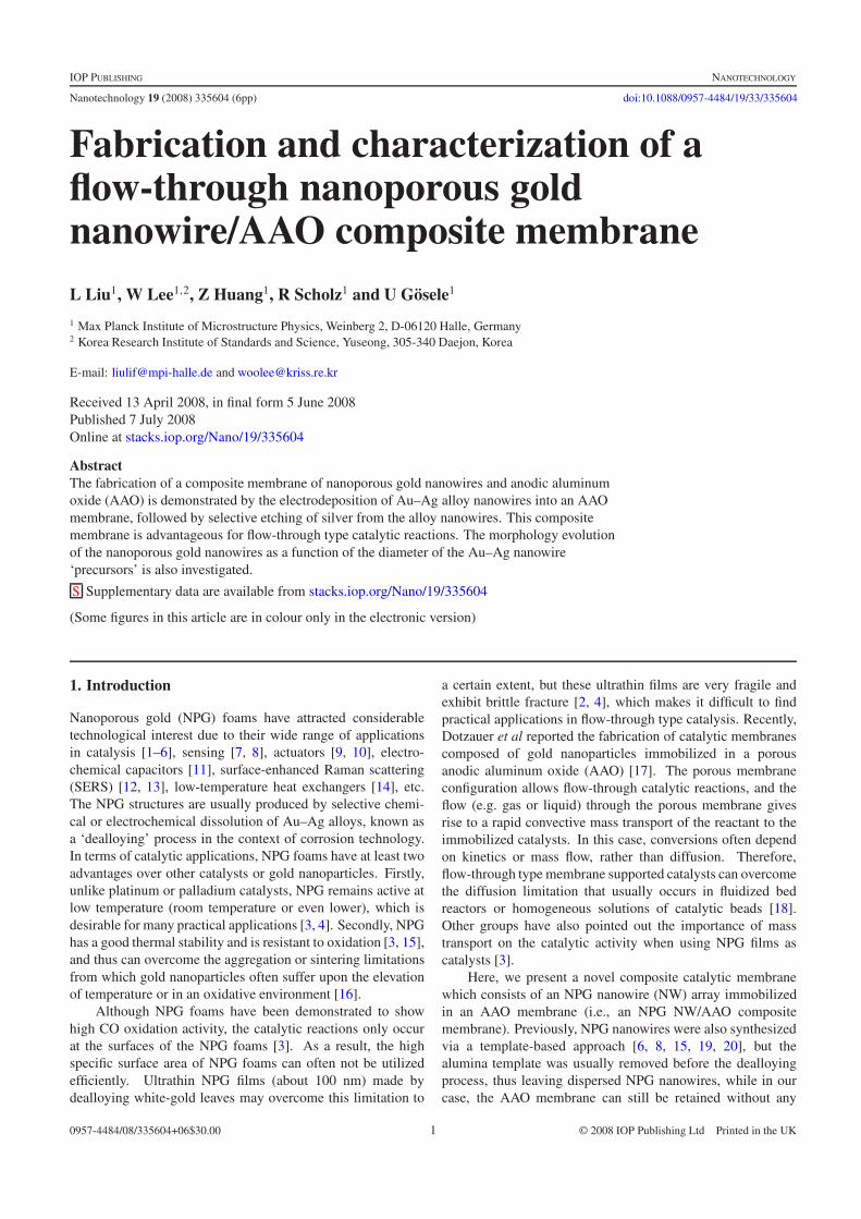
Figure 1. Schematic diagram of the fabrication of a flow-through NPG NW/AAO composite membrane. (a) Ag sputtering; (b) successiveelectrodeposition of Ag and Au–Ag alloy NWs into the AAO membrane; (c) chemical dissolution of Ag nanorod base electrodes and Ag fromthe Au–Ag alloy NWs by concentrated nitric acid.
fractures upon dealloying treatment, and it serves as a supportfor the NPG nanowire array. Since the AAO membrane ismechanically stable, it is expected that the NPG NW/AAOcomposite membrane can be easily handled and can bear largerflow pressure compared to ultrathin NPG films.
2. Experimental details
2.1. Preparation of AAO membranes
The AAO membranes used in our experiments wereprepared by a two-step anodization process as describedpreviously [21–23]. Briefly, high purity aluminum sheets(99.999%) were first electropolished in a mixture of HClO4
and C2H5OH (1:3 v/v) for 4 min. The polished Al sheetswere anodized in 1 wt% H3PO4 at 195 V or 0.3 M H2C2O4
at 40 V at 1 ◦C. The first anodizations were usually carriedout for 20 h. Subsequently, the anodized Al sheets wereput into an acid mixture (6 wt% H3PO4 and 1.8 wt% CrO3)to completely remove the porous layer. Then, the secondanodizations were conducted for 16 h at the same conditions asthe first anodizations. Free-standing alumina membranes wereobtained by etching away the underlying aluminum substrateswith a mixture of CuCl2 and HCl. The barrier layers were thenremoved by 10 wt% H3PO4 at 45 ◦C for 50 min for H3PO4-anodized AAO and 5 wt% H3PO4 at 30 ◦C for 35 min forH2C2O4-anodized AAO, respectively.
2.2. Preparation of NPG nanowires
Figure 1 schematically illustrates the fabrication procedure ofNPG NW/AAO composite membranes. Before electrodepo-sition, a layer of Ag was sputtered on one side of the mem-brane as a conductive layer. Ag nanorod base electrodes werefirst electrodeposited into the AAO membrane at galvanostaticmode with a current density of 1 mA cm−2. Subsequently, theAu–Ag alloy NWs were electrodeposited into the AAO mem-brane. The electrodeposition of the Au–Ag alloy was carriedout in a standard three-electrode electrochemical cell. The Ag-coated AAO membrane and platinum mesh were employed asworking and counter electrode, respectively, and a Ag/AgCl(saturated KCl solution) electrode was used as a reference elec-trode. The electrolyte was prepared by mixing commercialAu (Orotemp, major component KAu(CN)2) and Ag (Technic,major component KAg(CN)2) electroplating solutions with amolar ratio of Au+/Ag+ = 1:4. The composition of the al-loy NWs can be controlled by the deposition potentials and theconcentrations of [Au(CN)2]− and [Ag(CN)2]− in the precur-sor solution, as demonstrated by Ji et al [15, 20]. Therefore,
the porosity of NPG NWs can be readily adjusted. After elec-trodeposition, Au–Ag alloy NWs embedded in the AAO mem-brane were immersed into a concentrated nitric acid solution(Fluka, 65%) at 1 ◦C. In this process, nitric acid can selec-tively etch silver in Au–Ag alloy NWs as well as the silver inthe base electrode layer without affecting the AAO membrane(figure S1 (available at stacks.iop.org/Nano/19/335604)) [24],resulting in an NPG NW/AAO composite membrane.
2.3. Characterization of NPG nanowires
The morphology and structure of as-prepared NPG NWs werecharacterized by scanning electron microscopy (SEM, JEOL-6340F) and transmission electron microscopy (TEM, JEOL-1010 and Philips CM20T). To liberate NPG NWs from theAAO template for SEM and TEM observations, the templatecontaining NPG NWs was immersed into 2 M NaOH solutionat 45 ◦C for several hours. The as-obtained product wascentrifuged several times and then washed with a large amountof deionized water. For SEM examination, the NPG NWswere dispersed on a silicon substrate. The silicon substrate waspasted on an SEM sample stage with conductive carbon tape.For conventional TEM investigations, a drop of suspensioncontaining NPG NWs was placed on a carbon-coated coppergrid. To further investigate the microstructure, plan-view TEMimages of NPG NWs embedded within an AAO template werealso taken. For this characterization, TEM specimens wereprepared by first thinning down the AAO template containingNPG NWs mechanically, and then milling with Ar+ ions.
3. Results and discussion
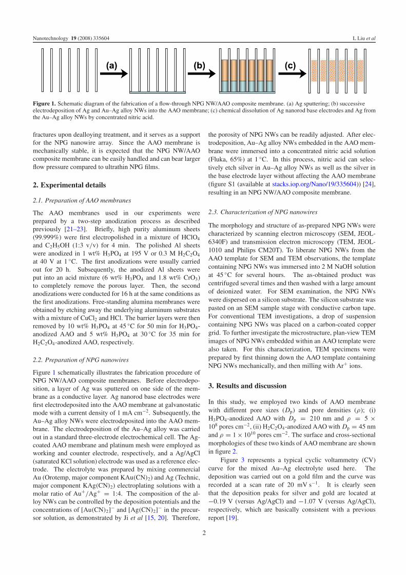
In this study, we employed two kinds of AAO membranewith different pore sizes (Dp) and pore densities (ρ); (i)H3PO4-anodized AAO with Dp = 210 nm and ρ = 5 ×10⁸ pores cm−2, (ii) H2C2O4-anodized AAO with Dp = 45 nmand ρ = 1 × 10¹⁰ pores cm−2. The surface and cross-sectionalmorphologies of these two kinds of AAO membrane are shownin figure 2.
Figure 3 represents a typical cyclic voltammetry (CV)curve for the mixed Au–Ag electrolyte used here. Thedeposition was carried out on a gold film and the curve wasrecorded at a scan rate of 20 mV s−1. It is clearly seenthat the deposition peaks for silver and gold are located at−0.19 V (versus Ag/AgCl) and −1.07 V (versus Ag/AgCl),respectively, which are basically consistent with a previousreport [19].
2
Nanotechnology 19 (2008) 335604 L Liu et al
Figure 2. Top view and cross-sectional SEM images of ((a), (b)) H3PO4-anodized and ((c), (d)) H2C2O4-anodized AAO membranes.
Figure 3. Cyclic voltammogram for the Au–Ag electrolyte on a goldfilm with a scan rate of 20 mV s−1.
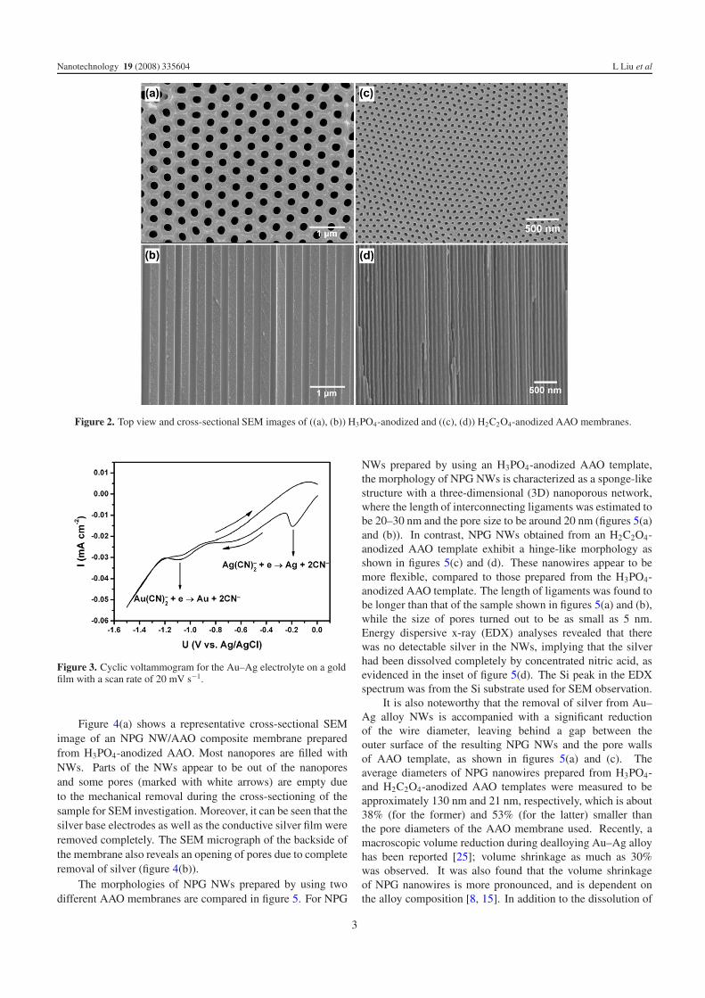
Figure 4(a) shows a representative cross-sectional SEMimage of an NPG NW/AAO composite membrane preparedfrom H3PO4-anodized AAO. Most nanopores are filled withNWs. Parts of the NWs appear to be out of the nanoporesand some pores (marked with white arrows) are empty dueto the mechanical removal during the cross-sectioning of thesample for SEM investigation. Moreover, it can be seen that thesilver base electrodes as well as the conductive silver film wereremoved completely. The SEM micrograph of the backside ofthe membrane also reveals an opening of pores due to completeremoval of silver (figure 4(b)).
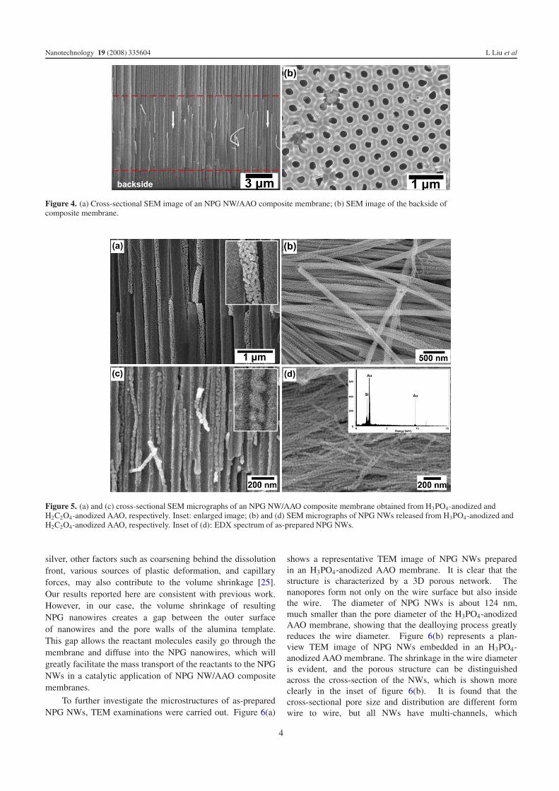
The morphologies of NPG NWs prepared by using twodifferent AAO membranes are compared in figure 5. For NPG
NWs prepared by using an H3PO4-anodized AAO template,the morphology of NPG NWs is characterized as a sponge-likestructure with a three-dimensional (3D) nanoporous network,where the length of interconnecting ligaments was estimated tobe 20–30 nm and the pore size to be around 20 nm (figures 5(a)and (b)). In contrast, NPG NWs obtained from an H2C2O4-anodized AAO template exhibit a hinge-like morphology asshown in figures 5(c) and (d). These nanowires appear to bemore flexible, compared to those prepared from the H3PO4-anodized AAO template. The length of ligaments was found tobe longer than that of the sample shown in figures 5(a) and (b),while the size of pores turned out to be as small as 5 nm.Energy dispersive x-ray (EDX) analyses revealed that therewas no detectable silver in the NWs, implying that the silverhad been dissolved completely by concentrated nitric acid, asevidenced in the inset of figure 5(d). The Si peak in the EDXspectrum was from the Si substrate used for SEM observation.
It is also noteworthy that the removal of silver from Au–Ag alloy NWs is accompanied with a significant reductionof the wire diameter, leaving behind a gap between theouter surface of the resulting NPG NWs and the pore wallsof AAO template, as shown in figures 5(a) and (c). Theaverage diameters of NPG nanowires prepared from H3PO4-and H2C2O4-anodized AAO templates were measured to beapproximately 130 nm and 21 nm, respectively, which is about38% (for the former) and 53% (for the latter) smaller thanthe pore diameters of the AAO membrane used. Recently, amacroscopic volume reduction during dealloying Au–Ag alloyhas been reported [25]; volume shrinkage as much as 30%was observed. It was also found that the volume shrinkageof NPG nanowires is more pronounced, and is dependent onthe alloy composition [8, 15]. In addition to the dissolution of
3
Nanotechnology 19 (2008) 335604 L Liu et al
Figure 4. (a) Cross-sectional SEM image of an NPG NW/AAO composite membrane; (b) SEM image of the backside ofcomposite membrane.
Figure 5. (a) and (c) cross-sectional SEM micrographs of an NPG NW/AAO composite membrane obtained from H3PO4-anodized andH2C2O4-anodized AAO, respectively. Inset: enlarged image; (b) and (d) SEM micrographs of NPG NWs released from H3PO4-anodized andH2C2O4-anodized AAO, respectively. Inset of (d): EDX spectrum of as-prepared NPG NWs.
silver, other factors such as coarsening behind the dissolutionfront, various sources of plastic deformation, and capillaryforces, may also contribute to the volume shrinkage [25].Our results reported here are consistent with previous work.However, in our case, the volume shrinkage of resultingNPG nanowires creates a gap between the outer surfaceof nanowires and the pore walls of the alumina template.This gap allows the reactant molecules easily go through themembrane and diffuse into the NPG nanowires, which willgreatly facilitate the mass transport of the reactants to the NPGNWs in a catalytic application of NPG NW/AAO compositemembranes.
To further investigate the microstructures of as-preparedNPG NWs, TEM examinations were carried out. Figure 6(a)
shows a representative TEM image of NPG NWs preparedin an H3PO4-anodized AAO membrane. It is clear that thestructure is characterized by a 3D porous network. Thenanopores form not only on the wire surface but also insidethe wire. The diameter of NPG NWs is about 124 nm,much smaller than the pore diameter of the H3PO4-anodizedAAO membrane, showing that the dealloying process greatlyreduces the wire diameter. Figure 6(b) represents a plan-view TEM image of NPG NWs embedded in an H3PO4-anodized AAO membrane. The shrinkage in the wire diameteris evident, and the porous structure can be distinguishedacross the cross-section of the NWs, which is shown moreclearly in the inset of figure 6(b). It is found that thecross-sectional pore size and distribution are different formwire to wire, but all NWs have multi-channels, which
4
Nanotechnology 19 (2008) 335604 L Liu et al
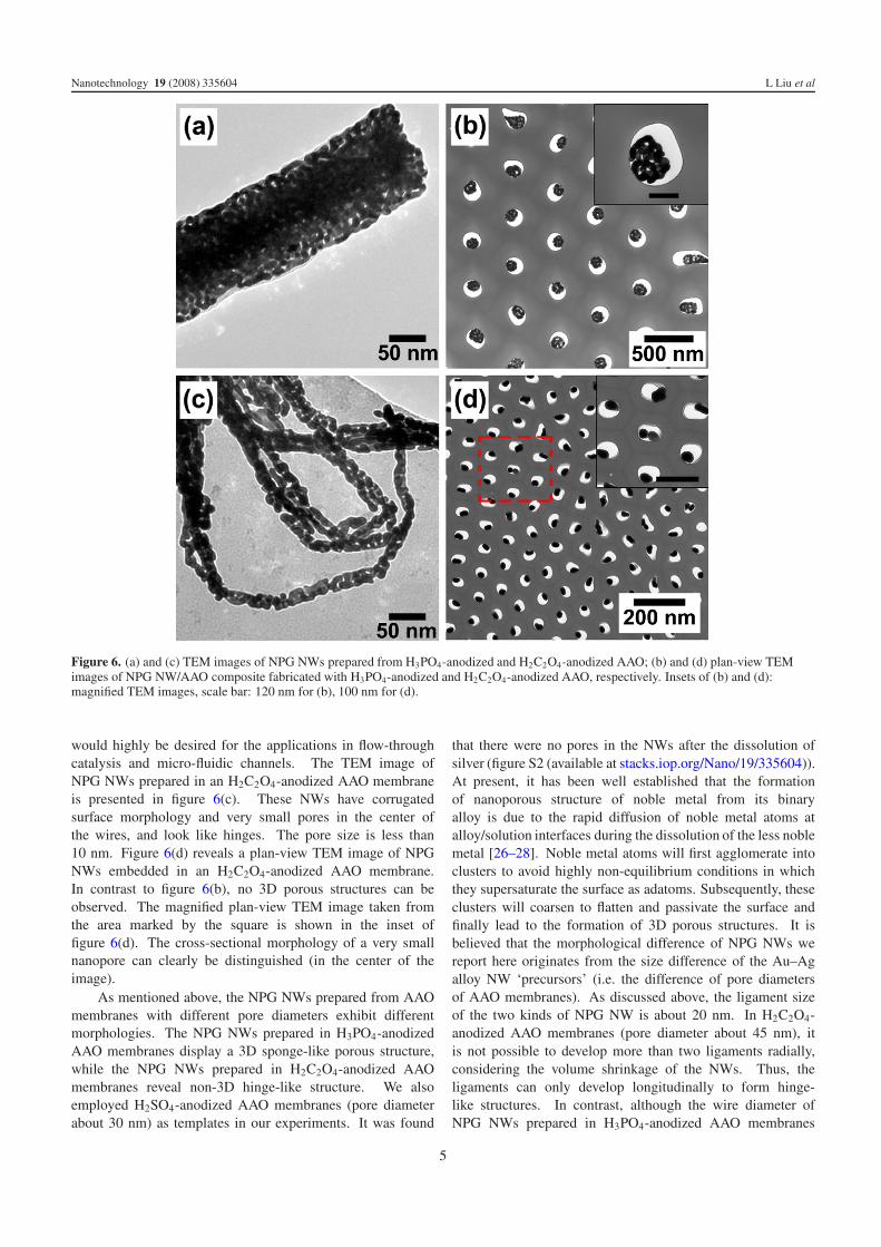
Figure 6. (a) and (c) TEM images of NPG NWs prepared from H3PO4-anodized and H2C2O4-anodized AAO; (b) and (d) plan-view TEMimages of NPG NW/AAO composite fabricated with H3PO4-anodized and H2C2O4-anodized AAO, respectively. Insets of (b) and (d):magnified TEM images, scale bar: 120 nm for (b), 100 nm for (d).
would highly be desired for the applications in flow-throughcatalysis and micro-fluidic channels. The TEM image ofNPG NWs prepared in an H2C2O4-anodized AAO membraneis presented in figure 6(c). These NWs have corrugatedsurface morphology and very small pores in the center ofthe wires, and look like hinges. The pore size is less than10 nm. Figure 6(d) reveals a plan-view TEM image of NPGNWs embedded in an H2C2O4-anodized AAO membrane.In contrast to figure 6(b), no 3D porous structures can beobserved. The magnified plan-view TEM image taken fromthe area marked by the square is shown in the inset offigure 6(d). The cross-sectional morphology of a very smallnanopore can clearly be distinguished (in the center of theimage).
As mentioned above, the NPG NWs prepared from AAOmembranes with different pore diameters exhibit differentmorphologies. The NPG NWs prepared in H3PO4-anodizedAAO membranes display a 3D sponge-like porous structure,while the NPG NWs prepared in H2C2O4-anodized AAOmembranes reveal non-3D hinge-like structure. We alsoemployed H2SO4-anodized AAO membranes (pore diameterabout 30 nm) as templates in our experiments. It was found
that there were no pores in the NWs after the dissolution ofsilver (figure S2 (available at stacks.iop.org/Nano/19/335604)).At present, it has been well established that the formationof nanoporous structure of noble metal from its binaryalloy is due to the rapid diffusion of noble metal atoms atalloy/solution interfaces during the dissolution of the less noblemetal [26–28]. Noble metal atoms will first agglomerate intoclusters to avoid highly non-equilibrium conditions in whichthey supersaturate the surface as adatoms. Subsequently, theseclusters will coarsen to flatten and passivate the surface andfinally lead to the formation of 3D porous structures. It isbelieved that the morphological difference of NPG NWs wereport here originates from the size difference of the Au–Agalloy NW ‘precursors’ (i.e. the difference of pore diametersof AAO membranes). As discussed above, the ligament sizeof the two kinds of NPG NW is about 20 nm. In H2C2O4-anodized AAO membranes (pore diameter about 45 nm), itis not possible to develop more than two ligaments radially,considering the volume shrinkage of the NWs. Thus, theligaments can only develop longitudinally to form hinge-like structures. In contrast, although the wire diameter ofNPG NWs prepared in H3PO4-anodized AAO membranes
5
Nanotechnology 19 (2008) 335604 L Liu et al
is also reduced greatly, it is still large enough to developligaments both radially and longitudinally so that a 3D porousnetwork can be formed. We noted that a morphologicaltransition in NPG ultrathin films from three dimensions totwo dimensions was also reported previously [2], and wasattributed to the ‘collapse’ of an original 3D structure due tothe continuous coarsening associated with extended etchingtime in nitric acid. This morphological transition of theNPG structure is etching-time induced, while in our case,the etching time of alloy nanowire ‘precursors’ in nitric acidis constant for all samples. Therefore, the observed hinge-like NPG structure (2D-like) and non-porous gold nanowires(1D-like), which were produced from H2C2O4- and H2SO4-anodized AAO respectively, are not due to the longer etchingtime of their ‘precursors’. Instead, they arise from the confinedspace in which the development of 3D network is limited.
4. Conclusions
In summary, nanoporous gold nanowire/AAO compositecatalytic membranes were fabricated. By combining theporous membrane configuration of AAO and the largecatalytically active surface area of nanoporous gold nanowires,this composite membrane should be useful in flow-throughcatalysis. Furthermore, the morphological difference ofnanoporous gold nanowires prepared in AAO membranes withdifferent pore diameters was observed. It was shown that thediameter of the Au–Ag alloy nanowire ‘precursors’, that is, thepore diameter of the AAO membrane, has a significant impacton the diffusion and rearrangement of gold atoms during theselective dissolution of silver from the alloy nanowires. Thisfinding may facilitate further understanding of the formationmechanism of porous nanostructures during the dealloyingprocess in confined environments.
Acknowledgment
We acknowledge financial support from the German ResearchFoundation (STE 1127/8-1).
References
[1] Ding Y and Erlebacher J 2003 J. Am. Chem. Soc. 125 7772[2] Ding Y, Kim Y J and Erlebacher J 2004 Adv. Mater. 16 1897[3] Zielasek V, Jurgens B, Schulz C, Biener J, Biener M M,
Hamza A V and Baumer M 2006 Angew. Chem. Int. Edn45 8241
[4] Xu C X, Su J X, Xu X H, Liu P P, Zhao H J, Tian F andDing Y 2007 J. Am. Chem. Soc. 129 42
[5] Cattarin S, Kramer D, Lui A and Musiani M M 2007 J. Phys.Chem. C 111 12643
[6] Yoo S H and Park S 2007 Adv. Mater. 19 1612[7] Van-Noort D and Mandenius C F 2000 Biosens. Bioelectron.
15 203[8] Liu Z and Searson P C 2006 J. Phys. Chem. B 110 4318[9] Weissmuller J, Viswanath R N, Kramer D, Zimmer P,
Wurschum R and Gleiter H 2003 Science 300 312[10] Kramer D, Viswanath R N and Weissmuller J 2004 Nano Lett.
4 793[11] Cortie M B, Maaroof A I and Smith G B 2005 Gold Bull. 38 14[12] Kucheyev S O, Hayes J R, Biener J, Huser T, Talley C E and
Hamza A V 2006 Appl. Phys. Lett. 89 053102[13] Qian L H, Yan X Q, Fujita T, Inoue A and Chen M W 2007
Appl. Phys. Lett. 90 53120[14] Ertenberg R W, Angraka B and Takano Y 2000 Physica B
284 2022[15] Ji C X and Searson P C 2003 J. Phys. Chem. B 107 4494[16] Choudhary T V and Goodman D W 2005 Appl. Catal. A
291 32[17] Dotzauer D M, Dai J, Sun L and Bruening M L 2006
Nano Lett. 6 2268[18] Julbe A, Farrusseng D and Guizard C 2001 J. Membr. Sci.
181 3[19] Ji C X, Oskam G, Ding Y, Erlebacher J D, Wagner A J and
Searson P C 2003 J. Electrochem. Soc. 150 C523[20] Ji C X and Searson P C 2002 Appl. Phys. Lett. 81 4437[21] Lee W, Scholz R, Nielsch K and Gosele U 2005 Angew. Chem.
Int. Edn 44 6050[22] Liu L et al 2006 J. Phys. Chem. B 110 20158[23] Liu L et al 2006 J. Phys. D: Appl. Phys. 39 3939[24] Hornyak G L, Patrissi C J and Martin C R 1997 J. Phys. Chem.
B 101 1548[25] Parida S, Kramer D, Volkert C A, Rosner H, Erlebacher J and
Weissmuller J 2006 Phys. Rev. Lett. 97 035504[26] Erlebacher J, Aziz M J, Kanna A, Dimitrov N and
Sieradzki K 2001 Nature 410 450[27] Erlebacher J 2004 J. Electrochem. Soc. 151 C614[28] Pickering H W and Wagner C 1967 J. Electrochem. Soc.
114 698
6