Fabrication and characterisation of polymer optical fibers...
38
Cliapter: 1 The whole of science is nothing more than a refinement of everyday thinking- Albert Einstein (j!oCymer (j!/iotonics: jln Overview ":J;iqer optics IJas>emerged as -. astfiing sY$le11ls.Glass jiberspavetl:"ihe waY;'lor ...:. 'efficient· data traffic between continelJis with very. high t!a/a . rates, which was thoughtto be it1J.possi,ble a few years befor-e • .. The path o/glass fibers is being polymer optical ji/Jers. Polymer optical wave-guide is still in infancyand a lot of researchJ;vorkhas been taking place/or the fabrication o/low loss, efficientpolymers for fiber and integrated optics.
Transcript of Fabrication and characterisation of polymer optical fibers...

Cliapter: 1
The whole of science is nothing more than a refinement of everyday thinkingAlbert Einstein
(j!oCymer (j!/iotonics:jln Overview
":J;iqer optics IJas>emerged as -. astfiing l!ack~imi!lor"'~(j'inh,Jlnica#on sY$le11ls.Glass jiberspavetl:"ihe waY;'lor
...:. 'efficient·data traffic between continelJis with very. high t!a/a
. rates, which was thought to be it1J.possi,ble a few years befor-e•.. The path o/glass fibers is beingfoll~~edbypolymer opticalji/Jers. Polymer optical wave-guide is still in it~. infancyand alot ofresearchJ;vorkhas been taking place/or the fabricationo/low loss, efficientpolymers for fiber and integrated optics.
{l'ofymn-pliotonics
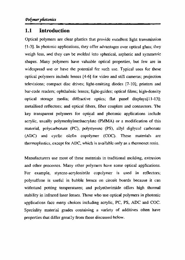
1.1 Introduction
Optical polymers are clear plastics that provide excellent light transmission
[1-3]. In photonic applications, they offer advantages over optical glass; they
weigh less, and they can be molded into spherical, aspheric and symmetric
shapes. Many polymers have valuable optical properties, but few are in
widespread use or have the potential for such use. Typical uses for these
optical polymers include lenses [4-6] for video and still cameras; projection
televisions; compact disc drives; light-emitting diodes [7-10]; printers and
bar-code readers; ophthalmic lenses; light-guides; optical films; high-density
optical storage media; diffractive optics; flat panel displays[ll-13];
metallised reflectors; and optical fibers, fiber couplers and connectors. The
key transparent polymers for opt~cal and photonic applications include
acrylic, usually polymethylmethacrylate (PMMA) or a modification of this
material, polycarbonate (PC), polystyrene (PS), allyl diglycol carbonate
(ADC) and cyclic olefin copolymer (COC). These materials are
thermoplastics, except for ADC, which is available only as a thermoset resin.
Manufacturers use most of these materials in traditional molding, extrusion
and other processes. Many other polymers have some optical applications.
For example, styrene-acrylonitrile copolymer is used in reflectors;
polysulfone is useful in bubble lenses on circuit boards because it can
withstand potting temperatures; and polyetherimide offers high thermal
stability in infrared laser lenses. Those who use optical polymers in photonic
applications face many choices including acrylic, PC, PS, ADC and COc.
Speciality material grades containing a variety of additives often have
properties that differ greatly from those discussed below.

Cliapter: 1
1.2 Optical properties of polymers
Optical properties of a polymer are light transmittance, yellowness, haze,
refractive index and Abbe number [14-16]. The polymers mentioned here
have light transmittance values exceeding 88 percent within the wavelength
range 380 to 1000 nm. PMMA and COC typically have 92 percent
transmittance over this range, while others fall somewhat lower. The high
refractive index of PC and PS limits their transmittance above 1000 nm. Fiber
optic systems can use higher transmittance bands between about 1200 to
1350 nm, and 1500 to 1600 nm. Some processing and end-use conditions can
cause optical polymers to acquire a yellow tint. High temperature (for
example, heat from lighting) and UV (from natural and artificial light) can
cause yellowing when in use. PS and PC tend to turn yellow more than
PMMA with UV exposure. Optics for collimating diode lasers and light
emitting diodes are among the potential applications of optical polymers.
Choosing the right plastic will determine the ultimate success of the
application.
The environmental stability of optical polymers (i.e. the stability of their
optical and mechanical characteristics with temperature and humidity) is an
important issue because most of the polymers do not have properties that are
appropriate for operation in communication environments. A key
characteristic for practical applications is the thermal stability of the optical
properties since organic materials may subject to yellowing upon thermal
induced oxidation. The presence of hydrogen in a polymer allows the
formation of Hydrogen-Halogen elimination products, which results in
carbon double bonds which are subjected to oxidation.

(]Jofymerpliotonics
Refractive index normally decreases as temperature or wavelength increases
(unlike in glass, where index increases with temperature). Component
designers can compensate for changes in refractive index by carefully
matching the polymer to the wavelength and by using composite glass-and
plastic lenses that compensate for higher temperatures [17-19].
Birefringence, the effect of variations in the index of refraction of a material
when measured in different directions, can occur in plastic components when
polymer chains align during molding. Careful management of molding
conditions can minimize birefringence and other effects of optical anisotropy.
Typically, lower injection speed and longer holding time contribute to
reducing birefringence. Physical f~rces on a component can also affect
birefringence. The proportionality between birefringence and applied stress is
the material's stress-optic coefficient. This is important in laser optics,
compact discs, polarized-light applications and precision optics, which must
minimize directional variations in refractive index.
The Abbe number is a measure of dispersion and indicates how refractive
index varies with wavelength. Dispersion is important in optoelectronic
systems that use relatively wide bandwidths. Correlating Abbe number and
refractive index shows that PMMA, ADC and COC fall within the realm
normally occupied by crown optical glasses and that of PS and PC are more
like flint glass. Optical properties may also change with wavelength,
temperature and moisture. For instance, the thermal effect of a high-power
laser beam passing through a polymer can influence refractive index change
that causes the beam to bloom or spread. Even in low- gaze plastics; this can
occur at energy densities higher than 100 to 200 W/cm2
•

Cliapter. 1
Other factors, such as surface roughness, gloss, internal contamination and
color, may also be of concern in developing photonic devices.
1.2.1. Other properties
Specifications for photonic applications usually extend beyond optical
properties to include a range of physical, mechanical, thermal and other
characteristics. Density, for instance, is significant because lower density
means lower optical component weight and material cost. Moisture
absorption can change a component's optical geometry, increases refractive
index slightly and causes optical inhomogeneities in acrylics and other
moisture-sensitive materials. Components also must meet a variety of
mechanical criteria: tensile and impact strength, hardness, elongation at
break, scratch resistance and flexural modulus (stiffness). Heat deflection
temperature, the temperature at which a polymer deflects a set distance under
a set load, determines the extent of deformation that may occur when optical
components are close to high-intensity bulbs or other heat sources. The
coefficient of linear thermal expansion affects the ability of plastic
components to hold dimensions precisely as temperature changes.
All of these polymers will replicate fine surface features under the right
circumstances. PC and PMMA are more difficult to force into fine features
during molding than are eoe and PS. ADC fills fine surface features because
it is liquid when cast. Optical polymers differ greatly in their chemical
resistance. Methanol, for instance, attacks both PC and PMMA, but not eoc,while the opposite is true for hexane. In developing a photonic component,
we have to determine the chemicals which the component will likely
encounter during its life cycle.

C1'ofymerpliotonics
1.2.2. Processing considerations
Another design consideration is ease of processing. The thermoplastic resins
PMMA, PS, PC and COC - can be injection-molded, but ADC must be cast.
Casting (i.e. reacting in a mold) typically takes about 17 hours at 140°c.
PMMA, PS, PC and COC generally flow well during molding, fill complex
molds well and have similar cycle times. Except for COC they should be
dried before molding to minimize the possibility of splay and yellowing.
Shear and cooling stresses during injection molding can cause
inhomogeneities in polymers. But care in processing can minimize these
variations.
PMMA and PS tend to process similarly at comparable temperatures. PC and
COC also have similar processing temperatures, which are about 100°C
higher than PMMA and PS. Processing temperature is in line with the end
use temperature capability for these materials. Optical thermoplastics can also
be cast, extruded onto formed rollers or machined. Cast optical parts made
from ADC and PMMA can have lower haze than molded parts because the
manufacturer can filter the reagents before casting. In addition, diamond
turning of cast or molded and annealed blanks can produce prototype
components and small production runs without the need for polishing. Cost is
not a hard-and-fast issue but depends on the volumes and grades purchased.
The cost of all of these materials is nearly insignificant for small components
such as fiber optic coupler lenses. Material costs naturally become higher as
components grow larger, but the processing time for large and thick lenses
usually is a more significant part of overall component cost.
ClUlpter: 1
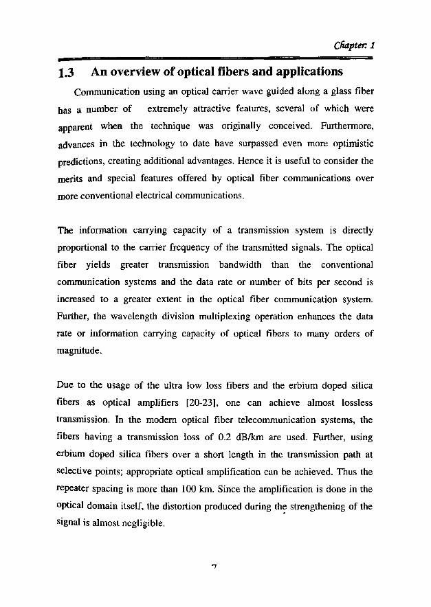
1.3 An overview of optical fibers and applications
Communication using an optical carrier wave guided along a glass fiber
has a number of extremely attractive features, several of which were
apparent when the technique was originally conceived. Furthermore,
advances in the technology to date have surpassed even more optimistic
predictions, creating additional advantages. Hence it is useful to consider the
merits and special features offered by optical fiber communications over
more conventional electrical communications.
The information carrying capacity of a transmission system is directly
proportional to the carrier frequency of the transmitted signals. The optical
fiber yields greater transmission bandwidth than the conventional
communication systems and the data rate or number of bits per second is
increased to a greater extent in the optical fiber communication system.
Further, the wavelength division multiplexing operation enhances the data
rate or information carrying capacity of optical fibers to many orders of
magnitude.
Due to the usage of the ultra low loss fibers and the erbium doped silica
fibers as optical amplifiers [20-23], one can achieve almost lossless
transmission. In the modem optical fiber telecommunication systems, the
fibers having a transmission loss of 0.2 dBIkm are used. Further, using
erbium doped silica fibers over a short length in the transmission path at
selective points; appropriate optical amplification can be achieved. Thus the
repeater spacing is more than 100 km. Since the amplification is done in the
optical domain itself, the distortion produced during th~ strengthening of the
signal is almost negligible.
fPofymerpliotonia
Since photons are considered to be chargeless particles they have a high
immunity to internal noise, cross talk, electrical noise, ringing, echoes or
electromagnetic interferences. It is also very immune to lightning, and thus
immune from lightning caused hazards. The transmitted signal through the
fibers does not radiate. Further the signal cannot be tapped from a fiber in an
easy manner. Therefore optical fiber communication provides hundred
percent signal security. Fiber optic cables are developed with small radii, and
they are flexible, compact and lightweight. The fiber cables can be bent or
twisted without damage. Further, the optical fiber cables are superior to the
copper cables in terms of storage, handling, installation and transportation,
maintaining comparable strength and durability, low risk of fire, explosion,
and ignition.
Due to the recent advancement in optical fiber technology, the fabrication
costs of optical fibers are coming down drastically. Even though the initial
cost of installation is very high when compared to electrical communication
cables, it has very low maintenance cost.
1.3.1 Materials used in the fabrication of optical fibers
There are a number of materials used for the fabrication of optical fibers. All
these materials are selected in such a manner that it satisfies certain
conditions, such as a) it should have good optical transmission quality for
efficient optical transmission b) it must be flexible and must be able to be
draw into long fibers and c) the cladding and the core materials should have
slightly different refractive indices to satisfy total internal reflection.
8
Cliapter. 1
Glass fibers
Glass fibers are mostly made from silica or silicates. Glass fibers are very
low loss fibers when compared to plastic fibers. Glass fibers are widely used
in longer distance communication purposes. There are a number of glass
fibers available, some among them are:
a) Silica glass fibers
They are made by fusing metal oxide, sulphides and selenides. Oxide
glasses are mostly used for making optically transparent glasses. The
most common is silica (Si02) , which has refractive index of 1.458 at
850nm. To produce two similar materials that have slightly different
refractive indices for core and cladding, various oxides are added to
silica.
b) Fluoride glass fibers
Fluoride glass fibers are used for optical fibers that have extremely low
transmission losses at mid IR wavelength region with the minimum loss
being around 2.55Jlm. Heavy metal fluoride glasses use ZrF. The
constituents of fluoride glass are mainly ZrF, BaF, LaF, AIF and NaF
referred to as ZBLAN. The material forms the core of a glass fiber. To
make a lower refractive index fiber, ZrF is partially replaced by HaF to
get a ZHBLAN cladding.
c) Active glass fibers
Active glass incorporates rare-earth elements into a normally passive
glass to give the resulting material which has new optical and magnetic
properties. These new properties allow the material to perform
amplification, attenuation and phase retardation of light passing through
it.

(]Jofymerpliotonics
d) Chalcogenide glass fibers
These contain at least one chalcogen element (S, Se, orTe) and typically
one other element such as P, I, Cl. It has high optical non-linearity and
long interaction length. Typically losses are in the range of IdB/m.
Polymer fibers:
In 1966, Dupont introduced the first type of Polymer Optical Fiber
(POF) product named Crofon with PMMA core to the market. The
development activities in the past 40 years were aimed at removing some
major disadvantages of POF, such as high transmission loss, low thermal
resistance and narrow bandwidth. Now various types of POF products
including GI type POF, single mode POF, fluorescent POF, non-linear POF,
etc. have been developed, which are widely used in the fields of light and
image transmitting, sensing, and information transmission in short distance.
POF is also largely used in illuminating, advertising, decorating, and art and
craft making, and low cost POF with Polystyrene (PS) core is mostly used in
such applications.
1.4 Polymer fiber optics
The global proliferation of optical fiber-based communication networks has
been the enabling factor in the shift from the Electronics Age to the
Information (i.e., Photonics) Age; as is supported by the exponential growth
in Internet subscription and video/multimedia conferencing. Silica glass
fibers have enabled this Information Superhighway, but plastic optical fibers
(POFs) are of great commercial interest because they can maintain flexibility
at thicker fiber sizes making them more easy to handle and install when the
communication systems make their way from the local loop (premise
If\

Cliapter: 1
networks, local area networks) closer towards, and into, the home. POF may
also be an important building block for devices used in future ultrafast all
optical communication systems because it has many attractive properties that
silica optical fiber lacks. An important one is its low processing temperature
(typically, less than 200°C). This allows organic nonlinear optical materials
to be incorporated into the POF, which is otherwise impossible in silica-based
fiber because of its high process temperature (typically 18000C to 2000°C).
Many useful devices, such as optical switches, may be constructed based on
fibers with fast response and high nonlinearity.
In general the polymers have certain advantages which make it a
suitable candidate for optical fiber fabrication. They are as follows:
• Easy mold and form into any shape
• High-impact applications(Inorganic materials such as glass ,
would shatter in such situations)
But, some of the problems are:
• Poor dimensional stability
• Poor scratch resistance
So far, highly purified inorganic glass core materials are still unsurpassed in
their low transmission loss or low attenuation. However, fibers made of glass
need to have very small diameters to obtain flexibility due to its high
Young's modulus. Furthermore, glass fibers are very brittle and very
sensitive to damage to the surface. This implies that connecting glass optical
fibers is a time consuming process that require high precision tools and
skilled workers. Polymer materials have a much lower modulus than
inorganic glass and therefore, can possess much larger diameter and still
retain their flexibility. Polymer optical fibers also possess a higher numerical
aperture (NA). As a result, the acceptance angle, or the light gathering
capacity, is large compared to glass optical fibers.
11

<Polymerpnotonia
Core Cladding AttenuationApplication
(dBlkm)All silica optical Long distancefibers Silica Silica 0.5 data
communicationPolymer PCF Short-Midclad Silica Silicone lO distance dataoptical communicationfibers
HPCF Mid distanceSilica
Fluorinated5 data
polymercommunication
Compound glass Short-Midoptical fibers distance data
Glass Glass 15 communicationIndustriallighting
Plastic optical~
Short distancefibers data
PMMAFluorinated
140communication
polymer Industriallighting,decoration
Table 1.1: Comparison of glass fibers with polymer fibers
The combination of large core diameter and high numerical aperture
facilitates fiber installation, which is a dominant cost factor. Accordingly, the
installation costs for POF system are much lower than for an inorganic glass
fiber network. For instance, cheap injection molded type of connectors are
used to establish POF links instead of the high precision ceramic ferrules
required for OOF links. What is more, no expensive lens systems are required
to couple the light into the fiber, due to the high numerical aperture. This
makes POFs a suitable candidate in short distance data communication
applications. Plastic optical fiber systems are found in local area network,
fiber to home applications, fiber optic sensor and the automotive [24] or
aviation [25J industry.
12

Cliapter. 1
1.4.1. Advantages of POF over silica flbers
• POF is very elastic in contrast to silica fiber, which is very brittle.
This property is important for the fiber interface within the opto
electronic systems where space is usually limited.
• Commercial POF has a typical diameter of Imm with no cladding or
only a thin cladding, making it a multimode fiber. The large core
diameter and flexibility allow ease of handling, large alignment
tolerance and connection cost.
• Low processing temperature (200°C to 250°C) of POF allows
organic nonlinear optical materials to be incorporated into the POF
which is otherwise impossible in silica fibers because of its high
processing temperature (lOOO°C to I500°C).
• The transmission windows of POF are distributed throughout the
visible wavelength range. The utilization of these windows will allow
very convenient and low cost deployment of POF systems.
• Silica fibers have very small non-linear coefficient requiring a large
amount of optical power or very long fiber length to induce sufficient
non-linear phase change. Polymer fibers can be made non linear by
appropriate doping material.
1.4.2 Application of polymer optical flbers
1. In Telecommunications:
Optical telecommunications using POF (Plastic Optical Fibers) have
not reached their potential for a number of reasons, the foremost being the
rapid growth of glass optical fiber technology and b~cause plastic optical
fibers have been relegated to low speed, short distance applications. As a
result of recent technical developments of graded index POF with bandwidths
13

(]Jofymerpfiotonia
of 3GHzl100m, single-mode POF, optical amplification in plastic fibers, new
POF materials with low loss at 1550nm and higher power and faster sources
have been developed. Applications such as FDDI, ATM, Escon, Fiber
channel, SONET, and FITH are now within the realm of plastic optical
fibers. Present interest is concerned with high-technology Local Area
Network applications. The real growth market is now, and will continue to be
simple point-to-point links in a wide range of applications across all
industries. Data Links for pes and workstations; Local Area Networks;
industrial data links; consumer digital data links; optical computing; optical
interconnects; automobile networks and links are some of the other
applications [26-30].
Polymers offer optical data transmission rates of 10 billion bits per second.
Optical fibers are being developed from polymer plastics (optically active
polymers), which would enhance the optical data transmission and optical
signal. Data is being transmitted increasingly over the public networks by
means of light traveling through optical fibers. Fiber-optic data transmission
also has significant advantages for the private sector. Among other things, it
permits the simultaneous transmission of several television programs and
facilitates rapid access to image and video documents via the Internet. To do
this, a computer, television set or telephone must be equipped with a so
called transceiver for connection to the fiber- optic cable. Normally the
transceiver comprises of a photodiode for receiving and a laser diode for
transmitting the optical signal.
2. Fiber amplifiers
Availability of inexpensive sources 10 the visible region has
increased the utilization of POF in data communication. Implementation of
optical communication in the visible region necessitates the development oflA.

Cfiapter.l
suitable optical amplifiers working in this region [31-36]. POF doped with
dyes or rare earth elements are potential candidates for this purpose. Laser
dyes, which act as highly efficient media for lasing and amplification have a
wide range of tunability in the visible region. The range of tunability of laser
dyes like Rhodamine B and Rhodamine 6G usually comes between 570nm to
640nm. The advantage of incorporating laser dyes in solid matrices such as
POF is that it is easier and safer to handle them than when they are in liquid
form. From recent studies it is found that the dye doped polymer materials
have better efficiency, beam quality and superior optical homogeneity when
compared to other solid matrices.
tLL:a1
Figure 1.1.A general dye doped fiber amplifierconfiguration
In dye doped optical fiber amplifiers the pump power can be limited to a very
low level and utilized in a most efficient manner since the power is well
confined to the core region and is propagated with less diffraction. The most
important aspect of reducing the pump power is that it reduces the bleaching
effects thereby increasing the stability of the medium. A general dye doped
amplifier configuration is shown in the figure 1.1.
The first step in the fabrication of dye doped POF is to develop doped
polymer preforms which can be fabricated following the standard fabrication
techniques, suitable for fiber drawing. The base material used for the
15
tpoCymerpliotonia
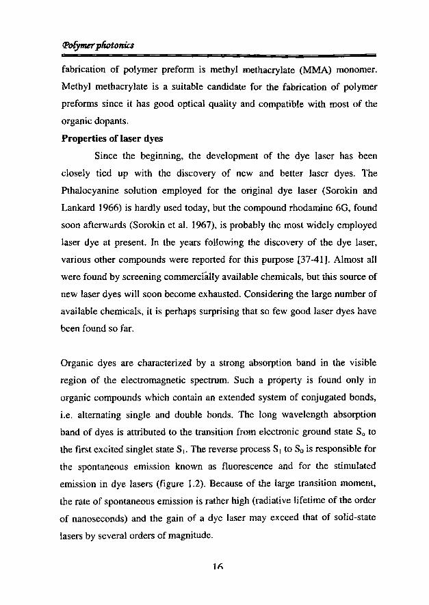
fabrication of polymer preform is methyl methacrylate (MMA) monomer.
Methyl methacrylate is a suitable candidate for the fabrication of polymer
preforms since it has good optical quality and compatible with most of the
organic dopants.
Properties of laser dyes
Since the beginning, the development of the dye laser has been
closely tied up with the discovery of new and better laser dyes. The
Pthalocyanine solution employed for the original dye laser (Sorokin and
Lankard 1966) is hardly used today, but the compound rhodamine 60, found
soon afterwards (Sorokin et a1. 1967), is probably the most widely employed
laser dye at present. In the years following the discovery of the dye laser,
various other compounds were reported for this purpose [37-41]. Almost all
were found by screening commercially available chemicals, but this source of
new laser dyes will soon become exhausted. Considering the large number of
available chemicals, it is perhaps surprising that so few good laser dyes have
been found so far.
Organic dyes are characterized by a strong absorption band in the visible
region of the electromagnetic spectrum. Such a property is found only in
organic compounds which contain an extended system of conjugated bonds,
Le. alternating single and double bonds. The long wavelength absorption
band of dyes is attributed to the transition from electronic ground state So to
the first excited singlet state SI' The reverse process SI to Sois responsible for
the spontaneous emission known as fluorescence and for the stimulated
emission in dye lasers (figure 1.2). Because of the large transition moment,
the rate of spontaneous emission is rather high (radiative lifetime of the order
of nanoseconds) and the gain of a dye laser may exceed that of solid-state
lasers by several orders of magnitude.
1(\

CfUzpter.1
-When the dye is pumped with an intense light source(flash lamp or laser), the
dye molecules are excited typically to some higher level in the singlet
manifold, from where they relax within picoseconds to the lowest vibronic
level of 51 Le. upper lasing level. For optimal lasing efficiency it would be
desirable for the dye molecules to remain in this level until they are called on
for stimulated emission. However, there are many nonradiative processes that
can compete effectively with the light emission and thus reduce the
fluorescence efficiency.
83
82
SI
SO
SINGLETSTATES
IIrII
~
~....l"'-l
""
~ z~ "<nt:: lau al~
TRIPLETSTATES
T3
T2
~
.... ~...~......
TI
Figure 1.2: Schematic energy levels of a dyemolecule.
These nonradiative processes can be grouped into those that cause a direct
relaxation to the ground state 50 (internal conversion) and those that are
responsible for intersystem crossing to the triplet manifold. Because of the
relatively long lifetime of the triplet molecules (of the order of microseconds)
the dye accumulates during the pumping process in the triplet state T h which
<Po{ymerpliotonia
often has considerable absorption for laser light. In addition to these general
requirements, an efficient laser dye in its first excited state should have
negligible absorption at the wavelength of the pump light and the laser
emission as well. Otherwise losses would occur, as in triplet absorption,
because the decay to the first excited singlet or triplet level is nonradiative.
Along with these properties, a laser dye should have an absorption spectrum
which matches the spectral distribution of the pump source.
3. Fiber optic sensors
Although many of the applications of optical fibers are based on their
capacity to transmit optical signals with low losses, it can also be desirable
for the optical fiber to be strongly affected by certain physical parameters of
the environment. In this way, it can be used as a sensor of such a parameter.
There are many strong arguments for the use of POF as sensors [42-46J, In
addition to their easiness to handle and low price, they present the advantages
common to all multimode optical fibers. Specifically, the flexibility and small
size of optical fibers enable a great sensitivity to be achieved without having
to occupy big volume. Moreover, it has been proved that POF can be
employed to detect a great variety of parameters, including temperature,
humidity, pressure, and presence of organic and inorganic compounds, wind
speed and refractive index. On the other hand, POF based optical sensors
eliminate the risk of electric sparks in explosive environments, and they can
be read from remote positions.
As an example to polymer optical fiber based sensor, several chemical
sensors have been developed using plastic optical fibers. The sensing
segment is made of porous polymer fiber, combined with selective chemical
indication systems. By careful selection of polymer systems and indicators,
the chemical reagents can be covalently bonded to the porous plastic fiber.
12

Cliapter: 1
-These sensors can be used to detect a variety of chemical species and to
measure various chemical parameters, both in vapor and solution. They
provide high sensitivity and stability. Sensor characteristics, including
dynamic range, linearity, and response time, can be tailored to meet specific
applications by altering the polymer composition and polymerization
procedure.
4. Polymer optical fiber passive devices
In telecommunication systems many passive optical fiber devices like
couplers, filters, scramblers, tapers and lenses are necessary. Their uses
depend on low insertion loss, mass production reliability, low-cost effective
production and thermal and mechanical stability. A general structure of a
simple fiber optic mode filter is shown in figure 1.3.
Flexiblecylinder
POFr ......,r-, ./
::::::.E:
11:::::::l
c:::~
c:
<; - ./
Figure 1.3: POF mode filter. The technique to make a modefilter is simple. Simply wrap a fiber around a cylinder.
Optical couplers are used not only in communication systems but also in
signalization, lighting, and decoration systems, where it is necessary to
distribute or redirect light to other outgoing fibers. Automotive, entertainment
and sensor industries represent other areas of potential application. The most
common techniques used for the fabrication of cou~lers are twisting and
fusion, side polishing, chemical etching, cutting, molding and gluing and
thermal deformation [47-48].
19

(Jt)fymerpliotonics
Large core optical fiber exhibits a large number of propagating modes. The
presence of such modes can cause modal noise in telecommunication
systems. This problem is significant for high-speed telecommunication
system. The technique to obtain a POF modal filter is rather simple: merely
wrap a POF segment around a small diameter cylinder.
In some applications, most of which are related to sensors, it is not only
necessary to filter higher order modes, but to scramble them. This treatment
is done to guarantee that an propagation modes carry the same power. The
device used for this application is called a scrambler. Mode scramblers [49]
have been designed and assembled that consist of polyester plate that has
induced microbends and a POF segment that is positioned to compress
against the microbends (figure 1.4).
Polyester plate
---""'~'\ , \ , ..... \\ , \ , \ '\ 1 \ I \ J~-' '-' ,-~
Figure 1.4: POF mode scrambler
POF
5. Fiber.optic lighting
Optical wave-guides are useful in lighting and illumination
applications. Especially light guides prepared from polymeric materials
possess a low weight, but high strength-to-weight ratio. Furthermore,
polymers are easily processed and hence result in a flexible layout design
using standard processing techniques such as compression molding, extrusion
and injection molding. The use of polymeric materials in lighting applications
Cli4pter.l
opens up a large number of applications in lightweight mobile devices and
also in the field of signage and displays as a replacement for high voltage
neon devices, which are rigid, fragile and limited in length.
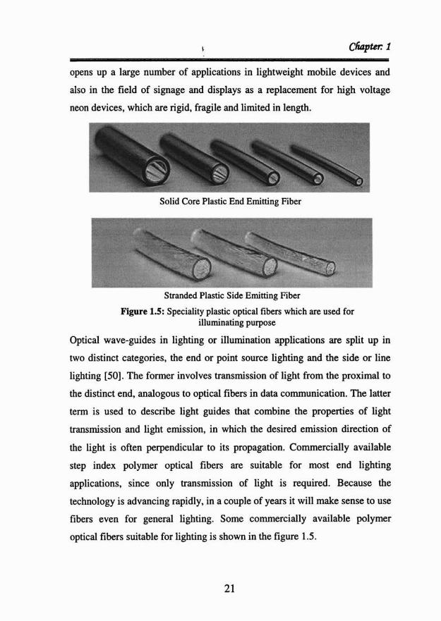
Solid Core Plastic End Emittin g Fiber
Stranded Plastic Side Emitting Fiber
Figure 1.5: Speciality plastic optical fibers which are used forilluminating purpose
Optical wave-guide s in lighting or illumination applications are split up in
two distinct categories , the end or point source lighting and the side or line
lighting [50] . The former involves transmission of light from the proximal to
the distinct end. analogous to optical fibers in data communication. The latter
term is used to describe light guides that combine the properties of light
transmis sion and light emission, in which the desired emission directi on of
the light is often perpendicular to its propagation. Commercially available
step index polymer optical fibers are suitable for most end lighting
applicatio ns, since only transmission of light is required. Because the
techno logy is advancing rapidly, in a couple of years it will make sense to use
fibers even for general lighting . Some commercially available polymer
optical fibers suitable for lighting is shown in the figure 1.5.
21

(J'ofymer pliotonia
1.4.3 Materials used for POF
PMMA
The material most frequently used for the fabrication of POF is the
thermoplastics PMMA (Polymethylmethacrylate), better known as Plexiglas.
From the beginning of 80's the available POF were found to have an
attenuation of around 150dB/km. PMMA-SI-POF has a theoretical minimum
attenuation of 106dB/km at 650nm [51-52J which is due to the Rayleigh
scattering and absorption of C-H bonds. In addition there are the losses
resulting from waveguide structure, particularly when taking into account the
attenuation resulting from cladding.
MMAPMMA
Figure 1.6: Structure of PMMA
PMMA [53-55] is produced from ethylene, hydrocyanic acid and methyl
alcohol. It is resistant to water, lyes, diluted acids, petrol, mineral oil and
turpentine oil. PMMA is an organic compound forming long chains with
typical molecular weight around ]05. PMMA is amorphous in nature when
polymerized and has a very good optical transparency. The density of PMMA
is 1.18g/cm2• Its tensile strength is approximately 7-8kN/cm2 [57]. The
refractive index of PMMA is 1.492 and glass transition temperature Tg lies
between +95°Cand +125°C. At room temperature and 50% relative humidity
the material can absorb upto 1.5% water, which also affects the attenuation
characteristics. The bond structure of PMMA is as shown in the figure 1.6.
22

Cliapter: 1
MMA monomer has eight C-H bonds. The vibrations of this compound or
more precisely its harmonic waves are a main cause for the losses
encountered in PMMA polymer fibers. [56, 57]. In particular the harmonic
waves at 627nm (6th harmonic wave) and 736nm (5th harmonic wave)
essentially determine the level of attenuation within the application range of
pMMA-POF because these are not narrow absorption lines but relatively
wide bands. There are many ways to reduce the absorption losses of polymer
fibers using different materials in which less or no C-H vibrations are present
such as deuterium, fluorine and chlorine. The list of possible materials which
can be used either for forming the core or cladding material with their
refractive indices for GI fibers are as given below.
MMA methyl methacrylate n=1.492
VPAc vinyl-phenylacetate n=I.567
VB vinyl benzoate n=1.576
PhMA phenyl methacrylate n=1.570
BzMA benzyImethacrylate n=1.562
BB bromobenzene n=I.56
BBP benzyl n butyl-phtalate n=I.54
DPS diphenyl-sulfide n=1.49
23

(PoEymerpliotonia
POF for higher temperatures
Fiber with higher temperature resistance is required primarily for use
in certain areas of automotive technology (engine compartment) and
automation technology. A typical characteristics for all these materials used
at temperatures over +100 QC is the higher attenuation compared to PMMA
fiber. The lowest attenuation values here are in the range between 650nm and
800nm. Due to the larger refractive index difference between, for example,
Polycarbonate (PC) as the core material (n=1.5l) and special polymers
serving as cladding (Teflon-AF), the NA of these fibers may reach up to 0.90.
Partially fluorinated PC fiber has a feature of showing good temperature
resistance up to 145QC
with a bandwidth at 200MHz-I00m [56].
\ , I \ I
OH-C- H 0\ I \O-C" ,/-?-C-~ 'IC - O-n~ -~H-T-H ~ -~ 0
If H H If H
nFigure 1.7: Structure of Polycarbonate
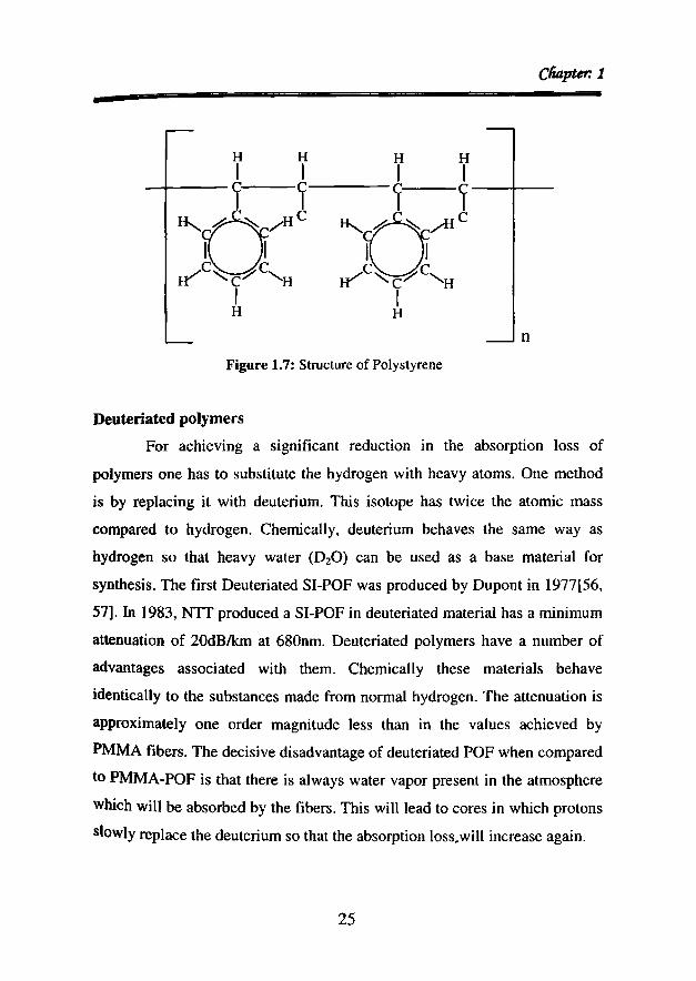
Polystyrene polymer flbers
Polystyrene is another suitable candidate for making POFs. Its molecular
structure is as shown in the figure 1.7. The initial fibers had an attenuation of
over 1,000dBIkm, later it was possible to reduce this to I 14dB/km at 670 nm.
The NA of these fibers which can be used at temperatures up to 70 QC is 0.56
Le. a little higher than that for standard PMMA-POF. The refractive index of
PS is n=1.59 so that it is possible to use PMMA as the cladding material
(n=1.49), as is possible for PC (n=1.48).
24
Cli4pter. 1-
n
Figure 1.7: Structure of Polystyrene
Deuteriated polymers
For achieving a significant reduction in the absorption loss of
polymers one has to substitute the hydrogen with heavy atoms. One method
is by replacing it with deuterium. This isotope has twice the atomic mass
compared to hydrogen. Chemically, deuterium behaves the same way as
hydrogen so that heavy water (DzO) can be used as a base material for
synthesis. The first Deuteriated SI-POF was produced by Dupont in 1977[56,
57]. In 1983, NTT produced a SI-POF in deuteriated material has a minimum
attenuation of 20dBIkm at 680nm. Deuteriated polymers have a number of
advantages associated with them. Chemically these materials behave
identically to the substances made from normal hydrogen. The attenuation is
approximately one order magnitude less than in the values achieved by
PMMA fibers. The decisive disadvantage of deuteriated POF when compared
to PMMA-POF is that there is always water vapor present in the atmosphere
which will be absorbed by the fibers. This will lead to cores in which protons
slowly replace the deuterium so that the absorption loss.will increase again.
25

<Polfymerpliotoniu
Fluorinated Polymers
The atomic mass of fluorine is many times greater than that of
hydrogen so that absorption bands are moved significantly further into the
infra-red zone. The theoretical minimum values are less than O.2dBIkm [56,
57]. i.e. comparable to silica fibers in the wavelength range of about
1,500nm. But in practice it is observed that it is very difficult to achieve those
results. Another important aspect is that it is very difficult to process a
fluorinated polymer processed in its amorphous state. Teflon material tends
to crystallize, which accounts for scattering losses within the fiber. An
interesting fact is that, PF- SI-POF has not produced yet simply due to the
fact that there are no suitable cladding materials available for this purpose.
Dye doped POF are expected to play a vital role in future communication
systems based on solitons as they can replace EDFA's which can operate
only in the IR region and thus allow for potential visible light communication
systems.
1.5 Polymer integrated optics
Polymer waveguide technology has a great potential for economic mass
production of complex planar photonic circuits that comply with the severe
requirements imposed by applications in communication systems [58-61J.
The low-cost prospect arises from the availability of a wide range of cheap
optical polymers and the simplicity of fabricating waveguides from them. A
significant subset of optical polymer materials has shown excellent optical,
chemical and mechanical characteristics that are very attractive for
applications in integrated optical devices as discussed previously. Polymers
can also be used for active routing, switching and even high speed
modulation of optical data, because all polymers have large thermo-optic
coefficients and , in addition , a variety of polymers have shown good
electro-optic properties. A large number of optical polymers have proven to
Cliapter: 1
-be thennally, chemically and mechanically stable, thus fulfilling the heavy
requirements needed for operation under harsh environmental conditions.
The most appealing characteristic of polymer waveguide technology is the
simplicity and flexibility of waveguide fabrication methods. Polymer thin
films can be deposited in a wide thickness range by spin or dip coating using
relatively simple equipment. A variety of channel waveguide fabrication
methods exist, ranging from existing micro-technology techniques such as
etching, to mass production methods developed especially for polymers,
including molding and laser delineation.
1.5.1 Polymer material properties for integrated optics
For a polymer to be selected as a material for wave guide technology, it has
to satisfy the following set of requirements: [62]
.:. Low optical losses (not more than 0.1dB/cm) in the
communication spectral windows around 800, 13000r 1500nm.
•:. Low wavelength dispersion
.:. Low birefringence
.:. Low polarization dependent losses
.:. Thermally stable optical and mechanical properties
.:. Resistant to humidity
.:. Good mechanical properties such as flexibility and roughness
.:. Low cost

lPofymerpliotonia
1.5.2 Fabrication of polymer optical waveguides
Fabrication methods used to produce polymer waveguides have to comply
with the following set of general demands
.:. Optical losses introduced by fabrication, such as that caused by
scattering on rough side walls, have to be kept a minimum.
•:. The method has to be simple and reproducible.
•:. The fabrication process should be suitable for low-cost mass
production
.:. High precision, sometimes well below lum is required.
There are at least three fundamental categories of channel waveguide
fabrication techniques, namely:
1. Optical lithography combined with wet etching.
2. molding
3. Photolithographic delineation
1.5.2.1 Optical lithography combined with wet etching
In optical lithography technique, first a polymer layer stack is deposited on a
polymer substrate. The first problem is the addition of the under-cladding to
the substrate and addition between subsequent polymer layers. A detailed
sketch is as shown in the figure 1.8. After the above mentioned process is
completed a deposition process is initiated by spin coating which should
result in crack-free homogeneous layer which covers the full chip area.
Between subsequent stages, the layers should be cured to avoid partial
dissolution of existing layers by freshly deposited layers [63].
The structure of the waveguide core can be defined by removing unwanted
parts of the core layer using an etching process. In such a process, first a core
layer is deposited by spin or dip coating on a lower index cladding layer.

Cli4pter.1
-After photolithography process using a photo resist, a waveguide pattern is
fonned. The channel waveguide is then realized by etching. Dry or wet
etching can be used to structure polymer waveguides. Among dry etching
reactive ion etching (RIE) is the most efficient and widely used because of
good selectivity, little undercut and high productivity [64].
Pure oxygen plasma is most commonly used to etch polymers. Certain gases
can be added to oxygen in the gas feed to enhance the concentration of highly
reactive atomic oxygen free radicals that increase the etching rate. One
common additive is tetrafluoromethane (CF4) .
1.5.2.2 Molding techniques
The term "molding" categorizes a number of low-cost replication techniques,
including casting, compression molding, injection molding, soft embossing,
hot embossing and LIGA (Lithographic Galvanoformung und
Abformung)[59,65,66]. The choice of the method is chiefly determined by
the polymer being used. Compression molding, like all other molding
techniques, requires a maid. A mold has to be created in the form of the
required structure in a mechanically polished brass substrate using a diamond
turning machine and replicating this structure in nickel using electroforming.
The compression molding process starts by depositing a film of polymer,
from which the structure is going to be made, on to a substrate. The thickness
of the deposited film should be equal to the height of the intended structure.
Then both the mold and the polymer film are heated to polymer Tg
temperature. After heating, the two parts are pressed together. The polymer
film, which is softened by heat, takes exactly the shape of the maid. The final
step involves hardening the created structure by heat treatment or DV curing.
29

Core layer
Undercladding
Subs le
Stepl: Deposition of wavegulding layerstack with underdadding and core layer
Step2: Photolithography process of theresist layer
~/. /
Step3: Formation of waveguide patternby photolithography
Step4: Realization of the channelwaveguide by etching.
Figure 1.8: Fabrication of polymer waveguide usinglithography and etching
3Q

SEM picture of polymeric multimode channelwaveguides
Top view of the etched waveguides by an opticalmicroscope
Figure 1.9: Cha nnel waveguides made by molding
31
Cfiapur: 1

(]1ofymerpliotonia
1.5.2.3 Photolithographic delineation
Polymer waveguides can be realized by externally induced dopant diffusion.
There are two types, namely, photolocking and selective polymerization. In
both, a monomer is doped with a certain photosensitive dopant. The doped
monomer is spun onto a substrate and the layer is exposed under a mask for
DV light. The dopants are locked into the host polymer during photo
polymerization reaction [66]. When the polymer material is heated after the
removal of the mask, the exposed regions are polymerized, whereas out
diffusion of the dopants can occur in the unexposed regions. In photolocking,
the core regions are exposed and the dopants in the cladding are out diffused,
which lower the refractive index because the dopants have higher refractive
index than that of the host polymer.
1.6 Polymer based integrated waveguide devices
Devices which are of great interest in optical communication and integrated
optics using polymers are power splitters, switches, modulators, wavelength
multiplexers/demultiplexers, optical cross-connects, dispersion
compensators, gain equalizers, light sources and optical amplifiers.
Due to relatively large thermo-optic coefficient of polymers, it is possible to
realize active devices that require low switching power. The main structure
used for thermo-optic devices are the Mach-Zehnder interferometers (MZI),
switched directional couplers (SDC) and digital optical switches (DOS) [62,
63]. In a system context the most important properties of a switch is its
isolation: the attenuation of power at an output port in the "off' state with
respect to the power at an output port in the "on "state. The isolation provided
by thermo optic polymer switches is not perfect. For MZI and SDC-type
switches even small errors in the waveguide dimensions or refractive index
can significantly reduce the attainable isolation below 20dB. Conversely, a
32

clUtpur. 1
•DOS has relatively liberal tolerances of birefringence, fabrication accuracy
and driving conditions. On the other hand switches can be combined to form
an n x m matrix that connects n inputs to m possible outputs.
Wavelength-division multiplexing (WDM) is currently the most important
technology in optical communications. Several polymer-based devices for
WDM applications have been demonstrated, such as optical filters,
demultiplexers and add-drop (de) multiplexers which involve electrooptic
polymer devices. Figure 1.10 shows the different polymer integrated optic
devices along with their transfer functions.
a) -- - -,....,- - - - - - - -, - .~ ,-, ... ---~ 1
1
I
10
b) ----------------------,,,
c)~igurel.l0: Important thermo-optic switching structures: a) Mach-ZehnderInterferometer; b) Switched directional coupler and c) digital optical switch.
The graphs show their corresponding idealized transfer functions
33

(pofymerpliotonia
1.7 Conclusion
In this chapter we discussed in detail the emergence of polymer photonics as
a potential field. Different types of polymers for application in fiber optics
and integrated optics were also discussed.

cli4pter. 1
References
1. Spangler, C. W., Suo, Z., Drobizhev, M., Karotki, A. and Rebane, A., "NewOrganic Dendrimers with Greatly Enhanced Multi-photon Absorption forPhotonics Applications", Organic Nanophotonics, NATO Science Series, F.Charra, V. M. Agranovich and F. Kajzar, Eds. Kluwer Academic Pub.,Doordrect, 1398 (2003).
2. L Eldada and L.W Shacklette," Advances in polymer integrated optics" •IEE.J. Select.Top.Quantum Electron,6,54,2000
3. L Eldada,' Advances in polymer integrated optical componernetry",Integrated Photonics Research Conference, Proc, IPR.lTUH1,200 I
4. B. Ward, A. C. Baker, and V. F. Humphrey "Nonlinear propagation appliedto the improvement of resolution in diagnostic medical ultrasound" J AcoustSoc ofAmerica 101, 143-154, 1997.
5. Paul C. Nicolson, Jurgen Vogt, "Soft contact lens polymers: an evolution"Biomaterials 22, 3273-3283, 2001
6. "Surface chemical structure for soft contact lenses as a function of polymerprocessing". J Biomed Mat Res, 32,45 - 54,1998
7. J. H. Burroughes, D. D. C. Bradley, A. R. Brown, R. N. Marks. K. Mackay,R. H. Friend. P. L. Burns and A. B. Holmes" Light-emitting diodes based onconjugated polymers" Nature 347, 539 - 541 1990
8. N. C. Greenharn, S. C. Moratti, D. D. C. Bradley, R. H. Friend and A. B.Holmes, "Efficient light-emitting diodes based on polymers with highelectron affinities". Nature 365,628 - 630, 1993.
9. V. L. CoIvin, M. C. Schlamp & A. P. Alivisatos, "Light-emitting diodesmade from cadmium selenide nanocrystals and a semiconducting polymer",Nature 370, 354 - 357, 1994.
10. Y. Yang and A. J. Heeger, "Polyaniline as a transparent electrode forpolymer light-emitting diodes: Lower operating voltage and higherefficiency". App Phy Lett, 64.1245-1247,1994.
11. P. E. Burrows, G. Gu, V. Bulovic, Z. Shen, S. R. Forrest, and M. E.Thompson "Achieving Full-Color Organic Light-Emitting Devices forLightweight. Flat-Panel Displays". IEEE Trans Elect Dev, 44,118,1997
12. G. Gu and Stephen R. Forrest, "Design of Flat-Panel Displays Based onOrganic Light-Emitting Devices". IEEE J. Sel Top Quant Elect, 4, 83.1998
13. Park S.K .• Han 1.1, Kim W.K., Kwak M.G, "Deposition of iridium-tin-oxidefilms on polymer substrates for application in plastic-based flat paneldisplays". Thin Solid Films. 397.49-55(7),2001.
14. Prediction of polymer properties.S'" ed, Jozef Bicerano, MarcellDekker,2002
15. Handbook of polymer science and technology, vol2, "Nicholas PChremisinoff", Marcell Dekker,1989
16. Photonic polymer systems, Fundamentals, methodS-and application, DonaldL Wise, Wise L Wise, Marcel Dekker, 1998
35

CPofymerpliotonics
17. Ruth H. Pater, "Interpenetrating polymer network approach to tough andmicrocracking resistant high temperature polymers. Part 11. LaRC-RP41",Poly Eng and Sci.3,20-27 ,2004.
18. G. Fischbeck, R. Moosburger, C. Kostrzewa, A. Achen, and K.Petermann,"Singlernode optical waveguides using a high temperature stablepoylmer with low losses in the 1.55pm range", Eec Lett, 33,518. 1997
19. AH Frazer, "High Temperature Resistant Polymers", New York,Interscience Publishers, 1968.
20. Philippe M. Becker, Anders A. Olsson, Jay R. Simpson, "Erbium-DopedFiber Amplifiers: Fundamentals and Technology", Lucent Technologies,Academic press, I999
21. E. Desurvire J. R. Simpson, P. C. Becke ,"High-gain erbium-dopedtraveling-wave fiber amplifier", Opt. lett., 12, 888,1987
22. Mori, A. Ohishi, Y. Sudo, S, "Erbium-doped tellurite glass fibre laser andamplifier", Elec. Lett., 33, 863-864, 1997
23. Miniscalco, WJ. ,"Ewrbium-doped glasses for fiber amplifiers at 1500nm", J. Light Wave Technology, 9, 234-250,1991
24. Kibler, T. Poferl, S. Bock, G. Huber, H.-P. Zeeb, E., "Optical databuses for automotive applications", J Lightwave.Tech, 22,2004
25. Cooper, K.R. Elster, J. Jones, M. Kelly, R.G ,"Optical fiber-basedcorrosion sensor systems- for health monitoringof aging aircraft",AUTOTESTCON Proceedings IEEE Systems Readiness TechnologyConference, 2001
26. Anthony Ng'oma, Ton Koonen, Idelfonso Tafur Monroy, Henrie van denBoom, Peter Smulders, Giok-Djan Khoe,"Low Cost Polymer Optical Fibrebased Transmission System for Feeding Integrated Broadband Wireless InHouse LANs", Proceedings Symposium IEEE/LEOS Benelux Chapter,Amsterdam,2002
27. H. P. A. van den Boom, W. Li, P. K. van Bennekom, Tafur Monroy, andGiok-Djan Khoe, "High-Capacity Transmission Over Polymer OpticalFiber", IEEE J SEL TOP QUAN ELEC, 7, 2001
28. Takaaki Ishigure, Yasuhiro Koike, and James W. F1eming ,"Optimum IndexProfile of the Perfluorinated Polymer-Based GI Polymer Optical Fiber andIts Dispersion Properties", J Lightwave.Tech, 18,2000
29. T. Ishigure, E. Nihei, and Y. Koike, "Optimum refractive-index profile ofthe graded-index polymer optical fiber, toward gigabit data links," Appl.Opt. 35, 2048, 1996
30. Andreas Neyer, Bj'orn Wittmann, and Matthias rohnck ,"Plastic-OpticalFiber-Based Parallel Optical Interconnects", IEEE J. SEL TOP QUANELEC, 5, 393,1999
31. A. Tagaya, S. Terarnoto, E. Nihei, K. Sasaki, and Y. Koike, "High-powerand high-gain organic dye-doped polymer optical fiber amplifiers: noveltechniques for preparation and spectral investigation ," Appl. Opt. 36, 572578,1997
32. A. Tagaya, Y. Koike, T. Kinoshita, E. Nihei, T. Yamamoto, and K. Sasaki,"Polymer optical fiber amplifier", App Phy Left. 63,883-884,1993
36
- ClUzpter.l
33. Tagaya, A. Teramoto, S. Yamamoto, T. Fujii, K. Nihei, E. Koike, Y.Sasaki, K., "Theoretical and experimental investigation of rhodamine B-dopedpolymer optical fiber amplifiers", IEEE J. QUAN ELEC, 31, 22152220, 1995.
34. C. Koeppen, S. Yamada, G. Jiang, A. F. Garito, and L. R. Dalton, "Rareearth organic complexes for amplification in polymer optical fibers andwaveguides," J. Opt. Soc. Am. B 14, 155, 1997.
35. Tsuyoshi Yamamoto, Kazuhito Fujii, Shigehiro Teramoto, Akihiro Tagaya,Eisuke Nihei, Takeshi Kinoshita, Yasuhiro Koike, and Keisuke Sasaki,"High-power polymer optical fiber amplifiers and their applications",Proceedings of SPIE. Doped Fiber Devices and Systems, 2289, 142-152,1994.
36. Gang Ding Peng Chu, P.K. Zhengjun Xiong Whitbread, T.W. Chaplin,R.P. ,"Dye-doped step-index polymer optical fiber for broad bandopticalamplification", J LlGHTWA VE TECH, 14, 22 I 5-2223,1996
37. P.P. Sorokin, J.R. Lankard and V.L Moruzzi,"Frequency- locking of organicdye lasers to atomic resonance lines", Appl.Phy.Lett,15, 179-181,1969
38. Snavely, B.B. ,"Flashlamp-excited organic dye lasers", Proceedings oftheIEEE, 57, 1374- 1390,1969
39. P. P. Sorokin and J. R. Lankard, "Infrared Laser Action in Sr VaporResulting from Optical Pumping and Inelastic Collisions", Phys. Rev. 186,342-343,1969
40. C. V. Shank,"Physics of dye lasers", Rev. Mod. Phys. 47,649-657,197541. P. P. Sorokin, J. R. Lankard, E. C. Hammond, V. L. Moruzzi, "Laser
pumped Stimulated Emission from Organic Dyes: Experimental Studies andAnalytical Comparisons", IBM J.Res.Dev, 11, 130, 1967
42. J. Zubia, G. Garitaonainda, and J. Arrue, "Passive Device Based on PlasticOptical Fibers to Determine the Indices of Refraction of Liquids ," Appl.Opt. 39,941-946,2000.
43. Bartlett R.J. Philip-Chandy R. Eldridge P. Merchant D.F. Morgan R., ScullyPJ., "Plastic optical fibre sensors and devices", Transactions ofthe InstituteofMeasurement and Control, 22, 431-457(27). 2000.
44. Philip-Chandy, R. Scully, P.J. Eldridge, P. Kadim, HJ. Grapin, M.G.Jonca, M.G. Dapos Ambrosio, M.G. Colin, F. , "An optical fiber sensorfor biofilm measurement using intensitymodulation and image analysis" ,IEEE J. SEL TOP QUAN ELEC, 6" 764-772, 2000
45. Masayuki Morisawa, Kohji Uchiyama, Toshiki Hosaka, Hideaki Inoue, andShinzo Muto, Akira Namazue, Eisuke Nihei, and Yasuhiro Koike, "Newcladding polymer for optical oxygen sensor using fluorescent plastic fiber",Proceedings of SPlE. Chemical, Biochemical, and Environmental FiberSensors Vlll, 2836, 336-340, 1996.
46. Zubia, J. Aresti, O. Arrue, J. Lopez-Amo, M ,"Barrier sensor based onplastic optical fiber to determine the windspeed at a wind generator", IEEEJ. SEL TOP QUAN ELEC, 6, 773-779, 2000
47. M.Naritomi," Proceedings of the Asia-Pecific Polymer optical Fiberworkshop", Sydney,38-59,200 I
37

(J'ofymerp&Jtonia
48. C.Ernst,R.Hohmann, M. Loddoch.C, Marheine and H Kargl,' Proceedingsof the international polymer optical fiber workshop", Sydney,95-96,2001
49. R.Attia and Marcou, "Mode scrambler for polymer optical fibers", Opt.eng;39,299,2000.
50. Andrew Bierman, Nadarajah Narendran, and Nishantha Maliyagoda, "Howto report light loss values for optical fibers used in fiber optic lightingapplications", Proceedings of SPIE Illumination and Source Engineering,3428, 62-72, 1998.
51. J. Brandrup, E.H. Immergut, D.R. Bloch and E.A. Grulke, PolymerHandbook (The), 2 Volume ,Wiley, 2003
52. A Ravve , Principles of Polymer Chemistry, Springer, 200053. Bruno Vollmert ,Polymer Chemistry, Springer- Verlag, 191554. Marvin J Weber, Weber J Weber ,Handbook of Optical Materials, CRC
Press, 200355. Marc J Madou , Fundamentals of Microfabrication, CRe Press, 200256. Werner Daum, Jrgen Krauser, Peter E Zamzow, Olaf Ziemann, Pof
Polymer Optical Fibers for Data Communication, Springer, 2002.57. Olagoke Olabisi, Handbook of Thermoplastics, Marcel Dekker, 199758. Y. Shi, C. Zhang, H. Zhang, J. H. Bechtel, L R. Dalton, B H. Robinson, W.
H. Steier, "Low (Sub DI-VQlt) Halfwave Voltage Polymeric Electro-opticModulators Achieved by Controlling Chromophore Shape" SCIENCE ,288,2000
59. Eldada, L. Shacklette, L.W. , "Advances in polymer integrated optics",IEEE J. SEL TOP QUAN ELEC, 6, 54-68, 2000
60. Eldada, L. Chengzeng Xu Stengel, K.M.T. Shacklette, L.W. Yardley,J.T. , "Laser-fabricated low-loss single-mode raised-rib waveguidingdevices in polymers", J Lightwave.Tech, 14, 1104-1713 ,1996
61. Louay Eldada, Robert Blomquist, Lawrence W. Shacklette, and Michael J.McFarland' "High-performance polymeric componentry for telecom anddatacom applications", Optical Engineering, 39, 596-609, 2000.
62. Hari Singh Nalwa, Polymer Optical Fibers, American Scientific Publishers,CA,2004
63. Sulur, Polymer Waveguides for GIPOF applications, Master Thesis,University of Twente, The Netherlands, 2001.
64. D. Elliot, "Micro lithography Process: Technology for IC Fabrication"McGraw-Hill, New York, 1986.
65. L Wu, ELi, S. Tang, B. Bihari and R.T. Chen, IEEE Photon. Technol.Lett,8,1647,1996.
66. Fischer, D. Voges, E, "Multimode polymeric waveguide devices fabricatedby two-componentinjection molding", Elect.Lett, 33, 1626-1627, 1991.
38