Fabricating Flax/Wood Pulp Fiber Hybrid Composites For Construction of Lightweight ... ·...
96
Fabricating Flax/Wood Pulp Fiber Hybrid Composites For Construction of Lightweight Sandwich Panels by Mariam Aijaz Khan A thesis submitted in conformity with the requirements for the degree of Masters of Science in Forestry Faculty of Forestry University of Toronto © Copyright by Mariam Aijaz Khan 2016
Transcript of Fabricating Flax/Wood Pulp Fiber Hybrid Composites For Construction of Lightweight ... ·...

Fabricating Flax/Wood Pulp Fiber Hybrid Composites For Construction of Lightweight Sandwich Panels
by
Mariam Aijaz Khan
A thesis submitted in conformity with the requirements for the degree of Masters of Science in Forestry
Faculty of Forestry University of Toronto
© Copyright by Mariam Aijaz Khan 2016
ii
Fabricating Flax/Wood Pulp Fiber Hybrid Composites For
Construction of Lightweight Sandwich Panels
Mariam Aijaz Khan
Masters of Science in Forestry
Faculty of Forestry
University of Toronto
2016
Abstract
The growing demand for natural materials is overtaking the composite sector for various applications.
However, use of natural fibers in structural applications is largely untapped. In this thesis, hybridization
of flax and wood pulp fibers reinforcing Poly-lactic acid (PLA) matrix is studied to produce lightweight
sandwich panels. Face and core composites were assembled using film stacking (of 30wt% fiber
loading) and wet-laying (of 50wt% fiber loading) process, respectively and hot pressed to form
composites. Mechanical properties were tested with varying composite weight ratios of untreated/alkali-
treated flax to pulp fibers. Tensile modulus of face composites showed a positive hybrid effect via
HROM and an overestimation by Halpin-Tsai. Compression strength of core composites showed an
increase of 67% by replacing 10wt% pulp fiber with flax fibers. Finally, sandwich panels, constructed
by hot pressing best combinations of face and core composites, showed core shearing as the primary
failure mode under flexural load.

iii
Acknowledgments
First and foremost, I would like to thank my supervisor, Prof. Ning Yan for her support and
guidance through my master’s degree. I have learned a lot about being a better graduate student,
a better researcher, and more curious about science and its advancements. I have had a privilege
being her student, and working with her lab members. I would also like to thank Forestry staff
members Tony Ung and Shiang Law for teaching me the instruments needed for my research. As
well, I would like to thank members of Composite Innovation Centre who provided detailed
reporting of fiber analysis.
As well, I would like to acknowledge financial support from NSERC Discovery and Agsci
Cluster Bioindustry Innovation Centre. Also, funding support via Queen Elizabeth II graduate
scholarship award.
Special thanks goes to Pei Yu Kuo, who has been very kind and generous with her time and
advices to help me build my thesis experiments. I am very grateful to have had her as my lab-
mate, office-mate, and friend. I enjoyed my time as a graduate student and met a lot of new
friends through her. Also, I would like to thank Rana Roy and Sharon Lee for their
encouragement and friendship throughout my program. And Bilal Sheikh for his generous offer
to help proofread and edit my thesis.
Most of all I would like to thank my family members, who have supported me through the
toughest struggles of life. I will be forever obliged for the sacrifices they have made. These two
years have truly transformed my affection and respect for each one of my siblings and parents.

iv
Table of Contents
Acknowledgments.......................................................................................................................... iii
Table of Contents ........................................................................................................................... iv
List of Tables ................................................................................................................................. vi
List of Figures ............................................................................................................................... vii
Introduction ......................................................................................................................................1
Thesis Overview..........................................................................................................................2
Literature Review ........................................................................................................................3
1.1 Flax Fibers ...........................................................................................................................3
1.1.1 Harvesting flax fibers ...............................................................................................4
1.1.2 Fiber structure and properties of flax fibers .............................................................6
1.2 Natural Fibers as Reinforcing Agents ..................................................................................7
1.2.1 Fiber reinforcing mechanisms ..................................................................................7
1.2.2 Fiber surface treatments ...........................................................................................9
1.2.3 Composite processing methods..............................................................................14
1.2.4 Hybridization in fiber composites ..........................................................................15
1.3 Biocomposites in Literature ...............................................................................................18
1.3.1 PLA Biocomposites ...............................................................................................18
1.3.2 Hybrid Biocomposites ...........................................................................................19
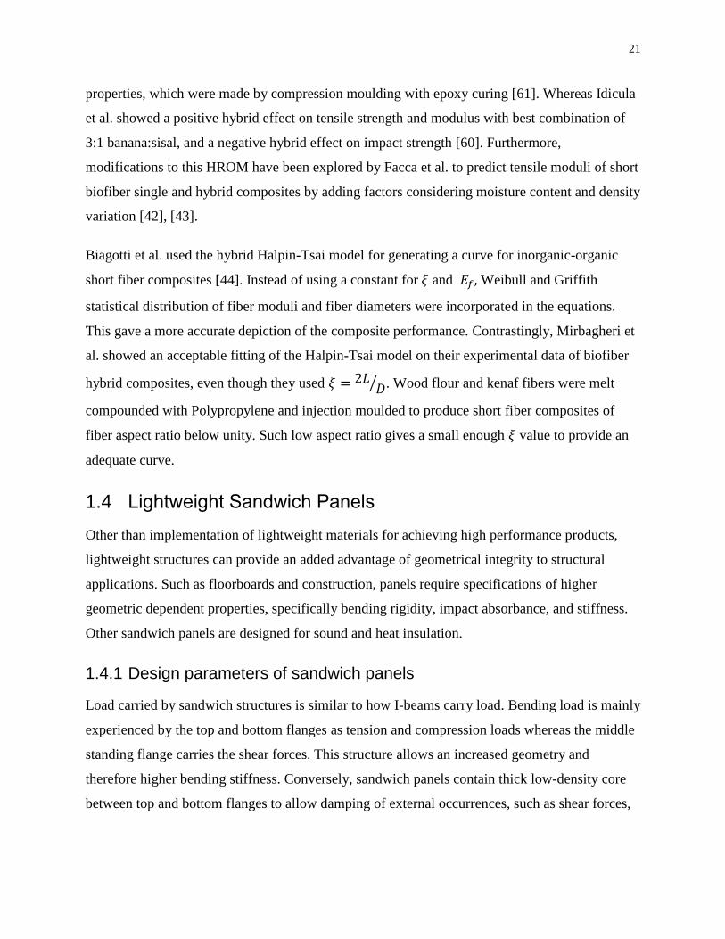
1.4 Lightweight Sandwich Panels ............................................................................................21
1.4.1 Design parameters of sandwich panels ..................................................................21
1.4.2 Lightweight sandwich panels in literature .............................................................25
1.5 Challenges ..........................................................................................................................26
1.6 Research Hypothesis and Contributions ............................................................................28
Flax/Pulp Laminate Sheet Composites .....................................................................................30
2.1 Experimental Setup for Laminate Sheet Composites ........................................................30

v
2.1.1 Materials for processing flax/pulp composites ......................................................30
2.1.2 Flax fiber preparation .............................................................................................31
2.1.3 Processing flax/pulp sheet composites...................................................................32
2.1.4 Characterization of raw materials and flax/pulp sheet composites ........................33
2.2 Results and Discussion for flax/pulp sheet composites .....................................................34
2.2.1 Analysis of raw materials and effect of alkalization ..............................................34
2.2.2 Tensile properties of flax/pulp laminate sheet composites ....................................44
2.2.3 Fracture morphology flax/pulp laminate sheet composites ...................................48
2.3 HROM and Halpin Tsai for Hybrid Laminate Sheet Composites .....................................53
2.4 Summary ............................................................................................................................57
Flax/Pulp Fibrous Core and Lightweight Sandwich structure ..................................................58
3.1 Experimental Setup for Core Composite and Sandwich Panel ..........................................58
3.1.1 Processing of core composites and sandwich panels .............................................58
3.1.2 Characterization of core composites and sandwich panels ....................................60
3.2 Results and Discussion for Core Composite and Sandwich Panel ....................................61
3.2.1 Compression properties of core composites ..........................................................61
3.2.2 Flexural properties and failure analysis of sandwich panels .................................65
3.2.3 SEM morphology of core composites and sandwich panels .................................67
3.3 Summary ............................................................................................................................69
Conclusion .....................................................................................................................................70
Future Work and Recommendations .............................................................................................71
References ......................................................................................................................................73
Appendix A: Flax fiber bundle analysis results .............................................................................83
Appendix B: Load-deflection curves of flax/pulp/PLA composites ..............................................86

vi
List of Tables
Table 1: Chemical composition of flax fibers [11] ......................................................................... 6
Table 2: Some common natural fiber surface treatments and coupling agents ............................ 11
Table 3: Materials and their description used for core and face composites ................................ 30
Table 4: Mechanical properties data of flax fibers and krat pulp fibers from literature ............... 30
Table 5: Laminate sheet composites with varying fiber loading of flax and pulp fibers.............. 33
Table 6: Peak positions of FTIR spectra of flax fibers and their corresponding representation of
molecular bonds and vibrations .................................................................................................... 38
Table 7: Thermal degradation analysis of raw materials of face composites ............................... 40
Table 8: Experimental and theoretical modulus values of flax/pulp laminate sheet composites . 56
Table 9: Fiber values and Halpin-Tsai parameters used for modelling composite modulus ........ 57
Table 10: Sandwich panel components and fiber loading in weight percent ............................... 60
Table 11: Flexural test results shown for FFF0F and FFF10F sandwich panels .......................... 67
Table 12: Analyses done on untreated flax fiber and their descriptions ....................................... 83
Table 13: XRD diffraction angle position for calculating cellulose crystallinity index of untreated
flax fibers ...................................................................................................................................... 84
Table 14: Fiber tensile test for untreated flax fiber bundles showing mean diameter and
corresponding tensile strength values. Highlighted rows show the closest representation to single
fiber tensile strength data .............................................................................................................. 85
vii
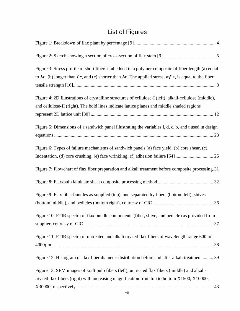
List of Figures
Figure 1: Breakdown of flax plant by percentage [9]. .................................................................... 4
Figure 2: Sketch showing a section of cross-section of flax stem [9]. ........................................... 5
Figure 3: Stress profile of short fibers embedded in a polymer composite of fiber length (a) equal
to 𝑳𝒄, (b) longer than 𝑳𝒄, and (c) shorter than 𝑳𝒄. The applied stress, 𝝈𝒇 ∗, is equal to the fiber
tensile strength [16]......................................................................................................................... 8
Figure 4: 2D Illustrations of crystalline structures of cellulose-I (left), alkali-cellulose (middle),
and cellulose-II (right). The bold lines indicate lattice planes and middle shaded regions
represent 2D lattice unit [30] ........................................................................................................ 12
Figure 5: Dimensions of a sandwich panel illustrating the variables l, d, c, b, and t used in design
equations ....................................................................................................................................... 23
Figure 6: Types of failure mechanisms of sandwich panels (a) face yield, (b) core shear, (c)
Indentation, (d) core crushing, (e) face wrinkling, (f) adhesion failure [64] ................................ 25
Figure 7: Flowchart of flax fiber preparation and alkali treatment before composite processing. 31
Figure 8: Flax/pulp laminate sheet composite processing method ............................................... 32
Figure 9: Flax fiber bundles as supplied (top), and separated by fibers (bottom left), shives
(bottom middle), and pedicles (bottom right), courtesy of CIC ................................................... 36
Figure 10: FTIR spectra of flax bundle components (fiber, shive, and pedicle) as provided from
supplier, courtesy of CIC .............................................................................................................. 37
Figure 11: FTIR spectra of untreated and alkali treated flax fibers of wavelength range 600 to
4000µm ......................................................................................................................................... 38
Figure 12: Histogram of flax fiber diameter distribution before and after alkali treatment ......... 39
Figure 13: SEM images of kraft pulp fibers (left), untreated flax fibers (middle) and alkali-
treated flax fibers (right) with increasing magnification from top to bottom X1500, X10000,
X30000, respectively. ................................................................................................................... 43

viii
Figure 14: Tensile strength of flax/pulp/PLA laminate sheet composites with and without alkali
treatment of flax fibers .................................................................................................................. 46
Figure 15: Tensile modulus of flax/pulp/PLA laminate sheet composites with and without alkali
treatment of flax fibers .................................................................................................................. 46
Figure 16: Optical microscopy images of tensile fracture surfaces of flax/pulp/PLA laminate
sheet composites ........................................................................................................................... 50
Figure 17: SEM images of tensile test fracture surfaces of flax/pulp/PLA laminate sheet
composites (a) – (k); yellow arrows point to pulp fibers and blue arrows point to flax fibers. .... 52
Figure 18: Pictorial depiction of the adjusted Halpin-Tsai equation for predicting flax/pulp
composites..................................................................................................................................... 55
Figure 19: Young's modulus of flax/pulp laminate sheet composites showing experimental and
theoretical data .............................................................................................................................. 56
Figure 20: Schematic showing core composite processing method using wet-laid processing ... 59
Figure 21: Flow chart of core composite processing .................................................................... 59
Figure 22: Schematic showing hot pressing step of sandwich panels and their component
thicknesses and densities............................................................................................................... 60
Figure 23: Compression strength of core composites and corresponding normalized values at
0.26g/cm3 ...................................................................................................................................... 64
Figure 24: Compression modulus of core composites and corresponding normalized values at
0.26g/cm3...................................................................................................................................... 64
Figure 25: Images of sandwich composites post-flexural tests .................................................... 66
Figure 26: SEM images of sandwich panel cross-section: (a) face-core interface, (b) 10F core, (c)
0F core .......................................................................................................................................... 68
Figure 27: XRD spectra of untreated flax fibers showing intensity for I002 and Iam ..................... 84
ix
Figure 28: Load-deflection curve for face sheet composites tensile test ...................................... 86
Figure 29: Load-deflection curve for core compression test ........................................................ 87
Figure 30: Load-deflection curve for sandwich panel 3-point flexural test.................................. 87

1
Introduction
Our world today experiences global warming and depleting natural resources due to
anthropogenic pollution on land, in sea, and in the environment. High non-renewable resource
consumption, greenhouse gas emissions, toxic waste, and non-degradable landfills are
accelerating environmental deterioration worldwide and threatening animal and plant survival.
Especially, mass production of petroleum-based polymeric materials, which has overshadowed
the use of metals and ceramics since World War II, generates prominent figures of carbon
footprint and gas emissions each year [1]. To mitigate these negative impacts on the
environment, sustainable engineering practice is on the rise. Sustainability involves the
development of materials and processes which serve beneficial to present and future generations
by providing renewable, recyclable, and reusable alternatives to the existing disposable
materials. Therefore, a growing number of industries are incorporating naturally derived
polymeric materials as well as natural fibers to reinforce polymers to reduce dependence on
petrochemical materials and their composites.
Natural fibers are being vastly explored as reinforcing agents for enhancing strength-to-weight
performances of composite products in industry. Moreover, integration of natural materials for
manufacture use gives a promising advantage for the growth of forestry and agriculture market,
especially in Canada, and a boost to further research of natural fibers and explore the unlimited
applicability of bio-based materials.
The motivation for this thesis is to broaden the use of biocomposites towards structural
applications such as sandwich panels. Successful attempts can provide sustainable alternatives to
current synthetic materials used for sandwich panels with major advantages. These include
abundant renewable material resource, ease of raw material handling, lightweight products,
environmentally friendly disposable solutions, and lower negative impacts. Moreover, extent of
the sustainability of materials is ascertained through Life cycle analysis (LCA). LCA of a
material or a product systematically illustrates a cradle-to-grave cycle evaluation of energy and
resource consumption and greenhouse gas (GHG) emissions into the environment. Batouli and
Zhu compared LCA of kenaf and glass fiberboards for use in Structural Insulation Panels (SIPs)
for building insulation and construction [2]. Using an ISO standard assessment framework, they

2
determined that the use of kenaf fiberboards was less impactful in all aspects of the LCA
evaluation from extraction step to product use. Similarly, Duigou et al. studied the LCA of flax-
Poly L-Lactic Acid (PLLA) composites compared with that of glass-unsaturated polyester (UP)
[3]. They established that greatly significant amounts of non-renewable energy was consumed
and GHG emissions were produced by manufacturing a quantity of glass-UP composite with
equivalent strength/modulus performance compared to that of flax-PLLA composite. Likewise,
numerous studies in literature prove higher sustainability of using naturally derived materials
during each step of their lifetime compared to that of synthetic materials.
Therefore, this thesis project works towards replacing synthetic materials with biocomposites for
use in manufacturing higher performance lightweight structural materials. Applications of these
structural sandwich panels include construction panels for building and housing interiors, vehicle
floorings and structural components, marine yacht and boat interiors, etc.
Thesis Overview
Chapter 1 introduces the scope and motivation for the research being carried out for natural fiber
reinforced composites. It provides an extensive literature review to develop and identify the
hypothesis and thesis contributions. This chapter lays out in detail, in section 1.1, the production
and processing of agricultural fibers, specifically flax fibers, and their use as composite
reinforcing agents (in section 1.2 and 1.3). Furthermore, the scope and mechanical parameters of
lightweight sandwich panels is presented in section 1.4. Sections 1.5 and 1.6 discusses the
hypothesis and objectives of the thesis. Chapter 2 presents the experimental setup and procedure,
the variables and constants considered, the assumptions made, the results, and a general
discussion of fabricated face laminate composites. Chapter 3 entails an evaluation pertaining to
core composites and sandwich panels and their mechanical performance. Finally, the document
concludes the major findings of this research project and provides grounds for future work and
recommendations.
3
Literature Review
1.1 Flax Fibers
The agricultural industry in Canada is growing since the past few decades due to increasing
demand in food and livestock, and pharmaceuticals. Moreover, technological advancements have
allowed agricultural waste to be transformed into value added materials such as chemicals,
adhesives, and bioenergy. One high value route for natural materials is the manufacture of
lightweight biocomposites.
Specifically, agricultural flax fibers are a type of bast fibers which show high potential as fiber
reinforcing agents. Flax, introduced initially in Europe, is widely known for its use as linen since
the ancient Egyptian times. Canada is the largest producer of flax and exports worldwide with
major markets in China, Europe and USA [4]. Flax Council of Canada has estimated a steady
growth of demand and production of flax to 27 billion units/acre by 2020 [5]. Flax plants consist
of high value components used in food, textile and pharmaceutical industries worldwide.
Linen, the most commonly used textile, was needed for making garments, sheets, covers,
threadwork and in medicine. However, after World War II, the linen market diminished. Owing
to the boom of inexpensive synthetic alternatives to linen, the flax production in Europe fell
dramatically. Recently, the flax industry is growing in North America for the production of
linseed. The awareness of high Omega-3 content in linseed is increasing its demand in
pharmaceuticals and food. This is driving flax plants to grow in conditions optimum for seed
quality and yield. More mature plants, longer growth period relative to that of flax used in linen,
produce high quality seeds and, in contrast, low quality short fibers [4], [6]. These short flax
fibers contain high lipid and wax content, and is recycled back in farming because of their low
quality and no end use. Additionally, separated shives also hold no value and are used as mulch
or fillers for insulation in farming. In Canada, Schweitzer Mouduit International is one of the
only companies which extracts flax fibers for low value paper and pulp end-use such as cigarette
paper [6]. Therefore, to utilize flax plants efficiently and profitably, Canadian flax industry is
working on expanding the value of flax seeds and fibers. Research in Saskatchewan and
Manitoba is showing great promise in adding value to profitless flax stalk and support
sustainable engineering in the global community [7]. Composites Innovation Centre, Manitoba,

4
focuses one of their research projects in optimizing bast fiber quality for high-end composite
processing [8], [6]. Furthermore, the potential use for flax in biocomposites is still untapped and
requires extensive research of its harvest, treatment, and processing techniques.
1.1.1 Harvesting flax fibers
The flax plant consists of the stem (containing shives, pedicles, and fibers) and the seed, as
shown in Figure 1. Although the seed comprises only 10% of the flax plant, it generates highest
value products as it is widely used in the food industry as is or as linseed oil. On the other hand,
shives, major by-product of flax, are re-used in the agricultural sector as mulch for gardening and
litter for animals. And, flax fibers are processed and treated for textile production. Flax fibers can
be categorized as long (>10cm) and short (<10cm) which are both used in textile industries.
Long flax fibers are processed from specific cultivation of flax plants for linen production,
whereas short fibers, also called as tow flax, are a by-product from seed harvests and are used in
the manufacture of low-value products such as paper, canvas, ropes and insulating mats.
Figure 1: Breakdown of flax plant by percentage [9].
The harvest of flax plants includes separation of the flax seeds from the plant stalk, and removal
of shives and roots to process fibers. Specifically, the plant stalk consists of fiber bundles which
are needed to be extracted chemically for potential use in biocomposites. Figure 2 shows a
sketched part of a cross-section of flax stem. The surface (top) is covered with epidermis and
70% • Flax shives
20% • Flax fibers
10%• Flax seeds
and waste products

5
cuticle cells followed by flax fiber bundles, and a thick array of cells which are collectively
termed shives. The center (bottom) of the stem is hollow for water and nutrient transport. To
extract the fiber bundles and remove unwanted plant matter, retting process is carried out. After
retting, mechanical breaking and scutching allows separation of the fibers from the straw/shives
and removal of unwanted plant residue. Then, hackling refines the fibers and improves fiber
homogeneity [4], [10]. These fibers are then ready for use or spun as yarn and fabric. Generally,
extracting fibers is difficult from mature plants due to thickening of the cuticle layer and increase
of lipids and wax content [6].
Wet retting process, the least energy intensive retting process, of agricultural fibers involve
keeping the green harvested fiber bundles in water for chemical hydrolysis of the plant structure
and bacteria culture to damage the outermost cuticle layer of the stem. Longer retting time
further weakens the inter-bundle fiber bonding which assists in easier separation of the fibers in
the later steps. Other retting processes include laboratory enzymatic retting, which allows
controlled retting of the fibers to produce high strength fibers. Weyenburg et al. studied different
factors of processing that effect fiber properties, namely, retting time, hackling, and use of long
or tow fibers[10]. Retting time influences the chemical debonding of the fibers from the stalks.
Figure 2: Sketch showing a section of cross-section of flax stem [9].

6
1.1.2 Fiber structure and properties of flax fibers
Flax cell structure constitutes higher crystalline structure than cotton. Bundles consist of 10 – 40
fibers held together with lignin and high levels of pectin. Microscopic level single fibers have
uneven cross-section of about 20µm in equivalent diameter at a high variance. Thickest cell wall
layer is the S2 layer of secondary cell wall which constitutes parallel running cellulose fibrils
with hemicellulose running at a 5 - 10o spiral angle bonded together with lignin and pectin [4],
[11]. This layer provides the fiber with its high tensile strength properties. Each fibril consists of
microfibrils in nanoscale of crystalline cellulose chains bonded by amorphous matrix of
hemicellulose, lignin and pectin. Chemical composition and properties is provided in the table
below:
Table 1: Chemical composition of flax fibers [11]
CELLULOSE
(%)
HEMICELLULOSE
(%)
PECTIN
(%)
LIGNIN
(%)
WAX
(%)
MOISTURE
(wt%)
62 – 72 18.6 – 20.6 2.3 2.0 – 5.0 1.5 – 1.7 8 - 12
Natural fiber quality is directly influenced by the (i) growth and harvesting conditions, (ii) retting
and decortication processes, and (iii) fiber spinning processes. Other than the origins and species
of fibers, retting time and refining steps greatly alters the microstructure of the flax fibers which
can enhance the inherent species properties. Moreover, textile industries have researched
optimized techniques for producing fine flax fiber yarns with high dye affinity, crease and wear
resistance for high quality linen production [12]. Refining processes include alterations in
chemical composition by removal of non-cellulosic materials (lignin and pectin) to provide
homogeneous strength. Recently, stringent studies on the structure-property relationships of
natural fibers have driven higher potentials in extracting higher value from these fibers.
Introduction of natural fibers for use in construction and furniture have posed question on their
value for higher end applications. Since flax fibers, among other bast fiber types, show high
specific strength and modulus, there is untapped scope of applications where they can be used
and replace environmentally unsustainable synthetic materials.
7
1.2 Natural Fibers as Reinforcing Agents
With the growing demand for environmentally friendly products, there has been significant
increase in research on natural materials. This research includes characterizing and studying the
behaviors of various natural fiber species and types and their composites on a macro-, micro- and
nano- scale. These studies lead us in understanding the underlying mechanisms in which natural
fibers behave under mechanical load. Extensive research on natural fibers show their dependence
on species, origin of production, harvesting and treatment conditions, and processing conditions
that alter their chemistry and material properties [13]–[15]. Although, these factors do not
influence their behavior as fiber reinforcing agents and comply with existing composite theory
and reinforcing mechanisms.
1.2.1 Fiber reinforcing mechanisms
Fiber reinforced composites provide an increase in mechanical strength and modulus to their
corresponding polymer matrix. Successful stress transfer from low strength matrix to the
embedded high strength fibers achieves this strength increase. This induced stress transfer is
dependent on the interfacial bond between the fiber and matrix which allows the fibers to remain
embedded in the matrix even if stress is applied.
Along with fiber-matrix interface and fiber characteristics such as aspect ratio, homogeneity,
composite characteristics determined by processing technique such as critical length, fiber
dispersion/distribution within the matrix, residual stresses, thermal degradation, etc also play
important roles and are discussed further in section 2.2.3.
A minimum length of fiber must be embedded in the matrix to result in successful stress transfer
between the fiber and matrix and therefore an improvement in the composite tensile strength.
This minimum length is termed as the critical length, Lc, and is defined as
E1. 𝑳𝒄 =𝝈𝒇𝒅
𝟐𝛕𝒃 ,
where τ𝑏 is the interfacial bond strength, 𝑑 is the fiber diameter, and 𝜎𝑓 is the tensile strength of
the fiber. As the equation depicts, 𝐿𝑐 directly depends on fiber diameter and fiber strength, and
indirectly on fiber-matrix bond strength.
8
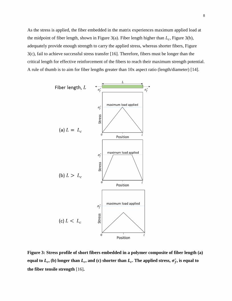
As the stress is applied, the fiber embedded in the matrix experiences maximum applied load at
the midpoint of fiber length, shown in Figure 3(a). Fiber length higher than 𝐿𝑐, Figure 3(b),
adequately provide enough strength to carry the applied stress, whereas shorter fibers, Figure
3(c), fail to achieve successful stress transfer [16]. Therefore, fibers must be longer than the
critical length for effective reinforcement of the fibers to reach their maximum strength potential.
A rule of thumb is to aim for fiber lengths greater than 10x aspect ratio (length/diameter) [14].
Figure 3: Stress profile of short fibers embedded in a polymer composite of fiber length (a)
equal to 𝑳𝒄, (b) longer than 𝑳𝒄, and (c) shorter than 𝑳𝒄. The applied stress, 𝝈𝒇∗ , is equal to
the fiber tensile strength [16].
9
Failure modes include fracture failure of fiber or matrix, and delamination failure of the fiber-
matrix interface. These modes can be distinguished by distinct fracture characteristics under
visual inspection and can appear collectively in composite failures. Fractures failures under
uniaxial tension show necking and plastic deformation of fibers at the fracture surface. In
contrast, delamination due to tension or shearing shows fiber pull-outs evidencing weak fiber-
matrix adhesion. Specifically, short fiber reinforced composites show high fiber pull-out zones
due to critical dependence of 𝐿𝑐 on τ𝑏. However, long fiber reinforced composite strength, of
fiber length greater than 10x 𝐿𝑐, is not significantly affected by τ𝑏. The fiber strength acts as the
primary factor in the fracture behaviour [17]. Literature concludes most natural fiber composites
undergone injection moulding processing produce fiber lengths of 0.1 – 1.2mm and aspect ratios
of <20 resulting in much smaller fibers than critical length [17]. These fibers then provides
minimal efficiency in reinforcing composite strength. Therefore, in order to design for successful
natural fiber reinforcing composites, various factors need to be addressed. Namely, fiber-matrix
interfacial bonding and fiber length play important roles in composite properties, which are
controlled by fiber surface treatments and composite processing methods, respectively.
1.2.2 Fiber surface treatments
Natural fibers show high polarity and hydrophilicity due to a large number of hydroxyl groups
present in cellulose molecules. This hydrophilic characteristic poses a major issue for reinforcing
commodity polymers, which are non-polar in nature. The difference in polarity creates high
repulsive forces between the two components resulting in negligible adhesion and reinforcing
effect. Additionally, the contrast in surface energies between the fiber and matrix lead to
decreased fiber wettability, weak bonding and hence, load transfer in a composite system. To
mitigate these issues, natural fibers are required to undergo surface treatments or modifications.
Treated fibers can then provide sufficient adhesion with the matrix phase to allow stress transfer
and strength enhancement. Therefore, fiber-matrix interfacial bonding is a major interest that is
being studied extensively for improving composite properties.
There are different types of interfacial bonding which occur between the fibers and the matrix in
a composite. These include:
1. Electrostatic interactions: net electric charge present between two components induce
weak attractive forces to achieve interfacial bonding.

10
2. Diffusion: ideal compatibility and surface characteristics of both components create
diffusion zones or a gradual phase change at the interface.
3. Mechanical interlock: rough and uneven fiber topography produces physical key and lock
interactions between the two components.
4. Adsorption and surface wetting: surface energy compatibility between fibers and matrix
dictate fiber wettability and effective adhesion.
5. Chemical bonding: chemical reactions of active sites create interfacial covalent bonding
Natural fibers without surface treatments primarily show signs of mechanical bonding between
the fibers and matrix. This is due to various characteristics that create strong mechanical
interlocking zones. These include a distribution of short fiber length, inhomogeneous fiber cross-
section, defects and rough fiber surface, bundles of microfibrils and defibrillated regions, fiber-
fiber networking abilities, and flexibility. Mechanical bonding prevents crack propagation by
providing a complex fiber network embedded in the matrix. However, this type of bonding
presents low interfacial bonding strengths and results in fiber pull-out zones at failure by axial
load, instead of fiber fracture. Additionally, weak interfacial adhesion implies presence of voids
and inhomogenous fiber dispersion and wetting which act as stress concentrating sites at the fiber
ends. This pre-mature failure reflects in the low mechanical properties of the composite system.
To achieve stronger interfacial bonding, fibers are modified to increase surface active sites for
chemical bonding. Cellulose molecules of natural fibers provide abundant hydroxyl groups
which readily react with coupling agents to provide preferred active sites for adhesion with the
polymer matrix. However, noncellulosic materials such as wax, lignin, and pectin hinder these
reactions are needed to be removed before chemical reactions can be taken place. Table 2
provides a list of common surface treatments done on fibers in order to improve fiber-matrix
interfacial adhesion. Washing with warm water is the least expensive way to help remove surface
debris and ash without breakdown of fiber bundles [18]. Dewaxing and delignification steps
expose cellulose molecules at the fiber surfaces by removing wax and lignin. These steps are pre-
treatments for reactions with coupling agents to produce excessive active sites for fiber-matrix
chemical bonding. Moreover, alkalization removes lignin and pectin and provides improved
interfacial bonding without any added coupling agents. This is explained by its action of
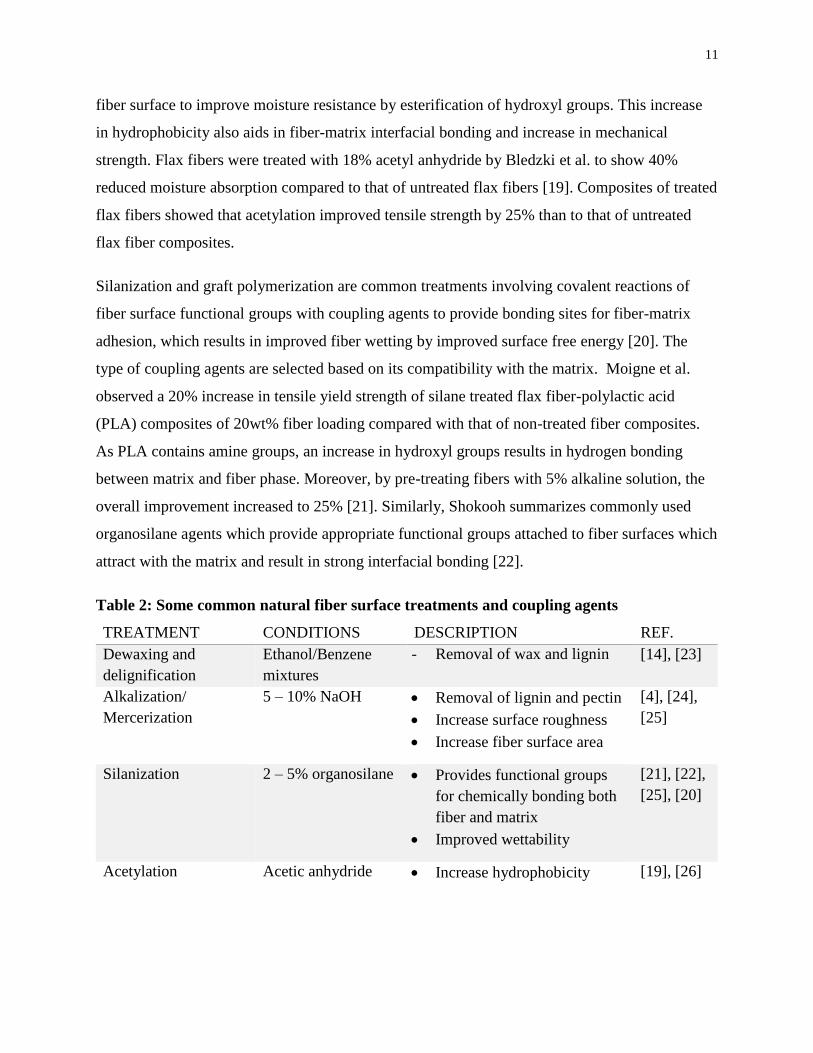
increasing fiber roughness, and surface area. Furthermore, acetylation treatments modify the
11
fiber surface to improve moisture resistance by esterification of hydroxyl groups. This increase
in hydrophobicity also aids in fiber-matrix interfacial bonding and increase in mechanical
strength. Flax fibers were treated with 18% acetyl anhydride by Bledzki et al. to show 40%
reduced moisture absorption compared to that of untreated flax fibers [19]. Composites of treated
flax fibers showed that acetylation improved tensile strength by 25% than to that of untreated
flax fiber composites.
Silanization and graft polymerization are common treatments involving covalent reactions of
fiber surface functional groups with coupling agents to provide bonding sites for fiber-matrix
adhesion, which results in improved fiber wetting by improved surface free energy [20]. The
type of coupling agents are selected based on its compatibility with the matrix. Moigne et al.
observed a 20% increase in tensile yield strength of silane treated flax fiber-polylactic acid
(PLA) composites of 20wt% fiber loading compared with that of non-treated fiber composites.
As PLA contains amine groups, an increase in hydroxyl groups results in hydrogen bonding
between matrix and fiber phase. Moreover, by pre-treating fibers with 5% alkaline solution, the
overall improvement increased to 25% [21]. Similarly, Shokooh summarizes commonly used
organosilane agents which provide appropriate functional groups attached to fiber surfaces which
attract with the matrix and result in strong interfacial bonding [22].
Table 2: Some common natural fiber surface treatments and coupling agents
TREATMENT CONDITIONS DESCRIPTION REF.
Dewaxing and
delignification
Ethanol/Benzene
mixtures
- Removal of wax and lignin [14], [23]
Alkalization/
Mercerization
5 – 10% NaOH Removal of lignin and pectin
Increase surface roughness
Increase fiber surface area
[4], [24],
[25]
Silanization 2 – 5% organosilane Provides functional groups
for chemically bonding both
fiber and matrix
Improved wettability
[21], [22],
[25], [20]
Acetylation Acetic anhydride Increase hydrophobicity [19], [26]

12
Graft co-
polymerization
Dependent on matrix Chemically bonds matrix
compatible monomers to
fiber surface
[14]
Of these fiber treatments, alkalization is concluded to be one of the most common and effective
treatments. Alkali treatment of natural fibers effect (i) chemical composition, (ii) surface
topography and surface area, (iii) micro-fibrillar spiral angle, (iv) cellulose crystalline structure,
(v) fiber dimensions, and (vi) tensile strength of the fiber [10], [12], [27]. These fiber
characteristics are very important in determining composite strength and are therefore studied
extensively. Ample literature is available on alkali treatment of flax fibers explaining the
mechanism and factors that influence successful fiber treatment [12], [18], [28], [29].
Figure 4: 2D Illustrations of crystalline structures of cellulose-I (left), alkali-cellulose
(middle), and cellulose-II (right). The bold lines indicate lattice planes and middle shaded
regions represent 2D lattice unit [30]
During alkalization, fibers are soaked in NaOH solution. The fibers absorb the solution and
swell. Sodium ions (Na+) carry water with them and replace the hydroxyl-hydrogen atoms.
During swelling, the natural cellulose crystalline structure, labelled as cellulose-I in Figure 4,
relaxes to conform into alkali-cellulose structure. This new structure increases in volume and
fills the gaps with water. Following washing with water, the complex cellulose structure converts
13
to cellulose-II, the sodium and hydroxyl ions diffuse out. Cellulose-II is known to be a more
thermodynamically stable structure than cellulose-I [10], [30]. The fibers, when oven dried,
contract to re-form hydroxyl groups within micro-fibrils, though somewhat to a lesser degree as
voids take place of water.
Changes in fiber microstructure and dimensions effect fiber mechanical properties. Swelling
during isometric alkali treatment increases the micro-fibrillar angle since the removal of lignin
and wax create voids and the absorbed water acts as a plasticizer. This loosens the dense and
tightly packed cellulose micro-fibrillar structure. Additionally, alkalization can result in swelling
of the fibers and up to 40% contraction of fiber length [12]. Tensile strain is increased with
higher shrinkage of the fibers which attributes to higher toughness and reduced impact damage
[12], [31], [32]. However, it also leads to decreased tensile strength and Young’s modulus. This
is because of increased deviation of cellulose microfibrils alignment from the loading direction,
as well as presence of voids between the loosened fibrils.
Therefore, shrinkage of flax fibers during alkalization must be mitigated in order ro result in
improved fiber strength and modulus. If fibers are stretched during treatment, the fibrils align
themselves along the load direction resulting in improved load sharing of the fibrils in the fiber
[24]. Moreover, microvoids between fibrils are eliminated without significant alterations to the
cells themselves. Furthermore, the treatment under tension leads to a decrease in spiral angle and
increase in molecular orientation which reflects in the improvement of the fibers Young’s
modulus [12], [24], [33]. Generally, untreated flax fibrils have a spiral angle of 5o, which allows
stretching of the fibrils along the tension deformation. This reduces with NaOH treatment under
tension and orients the fibrils along the loading axis.
Sharma has studied the influence of alkali treatment of flax fibers on the macro- and
microstructure of the fibers under slack and tension conditions on mechanical and moisture
absorption properties by using microscopy and thermal analysis. After treatment of 14% NaOH
solution at 25oC for 1hr under slack and tension condition showed fiber tenacity reduced from
4.1 to 1.0 and 2.1gf/den, respectively [12]. Water absorption tests show high swelling and
moisture regain of the slacked fibers. However, in tension, the swelling is significantly reduced.
TEM results showed contrasting characteristics of the cell walls of tension and slacked fiber

14
treatments in NaOH with latter showing inhomogeneous micro-fibrillar arrangements. On the
other hand, thermal analysis showed insignificant change in weight loss and peak degradation
temperature between untreated and NaOH treated in either slack or tension conditions.
At the fiber surface, alkaline solution dissolves lignin, pectin and wax on the surface and etches
away at the fiber surface [17]. It has been shown that stirring during treatment allow
defibrillation as removal of lignin and pectin, which bind the fibrils together, free the cellulose
fibers. Defibrillation is desirable for increasing fiber aspect ratio [27]. Additionally, long
treatment duration time and high alkaline concentration increases fiber roughness. Although fiber
roughness may induce mechanical interlock with the matrix phase for improved interfacial
bonding, increasing roughness can cause more fiber defects and increased amounts of amorphous
cellulose. Aydin et al. studied effects of 10%, 20% and 30% NaOH solution on treating flax
fibers for composite reinforcement [34]. Distinct reduction in mechanical property results were
observed with increasing solution concentration which is in agreement with other research
groups using alkaline solution higher than 5% in concentration [25], [29], [35]. Although Gassan
shows little influence of surface roughness on fiber-matrix interfacial adhesion [24]. Moreover,
fiber wettability and surface energy is also effected by the increased cellulosic functional groups
after alkalization of fibers. Fiber wettability decreases due to an increase in exposed hydrophilic
active sites of cellulose, by removal of surface oils and lignin, causing an increase in polar
surface energy and decrease in contact angle [36]. Thus, alkalization influences a number of flax
fiber characteristics that directly affect its performance as a reinforcing agent. Therefore, the
treatment procedure need to be investigated to achieve optimize a tradeoff between fiber
properties.
1.2.3 Composite processing methods
Processing methods explored for producing thermoplastic biocomposites are mostly focused on
the already established composite processing techniques. Optimizing biocomposite production
using established techniques such as melt mixing can provide an efficient transition for industries
to replace manufacture of synthetic composites. Melt mixing processes, such as extrusion,
compounding, and injection moulding, conveniently provide superior fiber distribution and
dispersion for non-biofibers with regulated manufacture of composites. However, some daunting
challenges faced by biofiber composite processing include:
15
(a) immense biofiber shearing and breakage leading to very short fibers,
(b) agglomeration of the short biofibers causing stress concentration sites and
inhomogeneity of reinforcement,
(c) biofiber degradation during melting and shearing steps of extrusion process, and
(d) only partial mechanical reinforcement due to random orientation and reduced biofiber
length [37]–[39].
Extrusion and high shear mixing of natural fibers at high temperatures cause breakage and result
in fiber lengths less than Lc. On top of that, natural fibers undergo thermal pyrolysis when
exposed to temperatures above 180oC. Subsequent reactions of sugars, proteins, and fatty acids,
as well as degradation of hemicellulose followed by lignin and cellulose, cause evident
discolouration, and significant drop in fiber properties. Consequently, even though fiber-matrix
interactions may improve with fiber treatments, fiber degradation and decreased fiber strength
result in insufficient strength enhancements of the composite. Furthermore, studies show
decrease in fiber properties with high mechanical processes for producing composites. Higher
quality fibers, thus composites with better properties, retain by undergoing lesser mechanical
processing steps [17]. Additionally, more processing adds on to the energy consumption of fiber
processing and contradicts the idea of sustainable engineering.
In addition to these conventional melt mixing processes, other commonly used processing
methods include resin transfer moulding, hand lay-up, compression moulding, thermoforming,
etc [3]. However, these methods are designed for continuous fibers or weaved fabrics which are
seldom commercially practiced for short discontinuous natural fibers.
1.2.4 Hybridization in fiber composites
Hybrid composites improve properties by synergizing the characteristics of more than one,
commonly two, constituent reinforcing fibers in an intricate composite system. The motivation
behind hybridization in a composite system is to not only synergize advantageous component
properties, but also cancel out property limitations for the overall composite. Established
research includes carbon and glass fiber hybrid composites for compromising density and cost of
constituent fibers [40].
16
There are three main hybrid configurations based on the degree of fiber dispersion within a
composite system: inter-layered or laminated fiber dispersion, intra-layered or dispersed fiber
bundles, and complete random fiber dispersion [40]. These different configurations are produced
by different processing techniques for specific material performance goals. Additionally, with
increasing fiber dispersion, theoretical models and property predictions get more and more
difficult to establish. Early hybrid composite studies explored the understanding of the
hybridization effect and consisted of continuous inorganic fiber laminate hybrid structures for
simplified prediction models. Accordingly, the established simple theoretical model for
evaluating hybrid effect uses hybrid rule of mixtures (HROM):
E2. 𝑋 = 𝑋1𝑉1 + 𝑋2𝑉2
E3. 𝐸 = 𝐸𝐶1𝑉1 + 𝐸𝐶2𝑉2
where XH is the characteristic property of hybrid composite, X1 and X2 are those of single fiber
composites of the respective reinforcing fibers, and V1 and V2 are volume fractions of the
respective fibers in the hybrid composite where V1 + V2 = 1. This characteristic property could be
Young’s modulus (as shown in E3), or shear modulus.
The hybrid effect studied in hybrid fiber composites, incorporates a relatively low elongation and
a relatively high elongation fiber type, and shows a deviation from the linear rule-of-mixtures
correlation. This deviation, may it be positive or negative depending on the property of interest,
can be explained by the different influential characteristics of constituent fibers and their
compatibility with each other. There are three major factors which have been mentioned in
literature which explains this hybrid effect:
1. Presence of residual strain due to coefficient of thermal expansion of fibers during and
after processing,
2. Initiation of crack propagation by localized fiber breakage and stress concentration sites
due to varying fiber moduli, and
3. Dynamic stress concentration observed via fiber-fiber interaction [40].
An experimental value curve with a maxima is denoted as a positive hybrid effect, whereas a
curve with a minima is denoted as a negative hybrid effect. Swolf strength and modulus shows a
17
positive whereas toughness and strain shows negative. However, the application of HROM is
limited to continuous fiber laminate hybrid composites.
Other than HROM, other micro-mechanical models have been built on existing single fiber
reinforced composites, which adjust to less simplistic hybrid systems. Such as, Halpin-Tsai, have
been modified to incorporate two fiber constituents instead of one. Halpin-Tsai is a set of semi-
empirical equations that allow for more accurate and fitting theoretical representation to the
experimental values [41]. Not only has this been used for fitting inorganic-inorganic hybrid fiber
composites, but has also been proven accurate for inorganic-biofiber and biofiber hybrid
composites.
The general form for Halpin-Tsai equation is [41]:
E4. Ω
Ω𝑚=
1+𝜉𝜂𝑉𝑓
1−𝜂𝑉𝑓,
where 𝜂 is expressed as:
E5. 𝜂 =(
Ω𝑓Ω𝑚
⁄ )−1
(Ω𝑓
Ω𝑚⁄ )+𝜉
In the equations above, Ω, Ω𝑓, and Ω𝑚 represent an interested material property of the fiber
composite, the fiber, and the matrix constituents, respectively. The material property calculated
may be longitudinal modulus, 𝐸𝑙𝑜𝑛𝑔, transverse modulus, 𝐸𝑡𝑟𝑎𝑛𝑠, or shear modulus, G. A fiber
correction factor, 𝜉, is a parameter used to fit the equation to the experimental data. This
parameter, although, empirical, quantitatively represents the effectiveness of fiber reinforcing the
modulus of the composite. It considers the packaging arrangement and fiber geometry [41].
Analytical equations have been developed for short fibers, of homogeneous geometry, for
calculating elastic and shear moduli of composites. For predicting 𝐸𝑙𝑜𝑛𝑔 reinforced with short
circular cross-section fibers, 𝜉 = 2𝐿𝐷⁄ , where 𝐿 is the fiber length, and 𝐷 is diameter. And, 𝜉 =
2 when calculating 𝐸𝑡𝑟𝑎𝑛𝑠 [41]. However, natural fibers possess inhomogeneous geometry along
the fiber length as well as show fibrillation, voids, kinks and elbows. Therefore, 𝜉 are usually
defined empirically to obtain best-fit curves for predicting composite modulus [42].

18
Below are the hybrid Halpin-Tsai equations for 𝐸𝑙𝑜𝑛𝑔 and 𝐸𝑡𝑟𝑎𝑛𝑠 of two fiber moduli 𝐸1 and 𝐸2.
These are used to calculate 𝐸𝑟𝑎𝑛𝑑𝑜𝑚 for by using 3:5 ratio of 𝐸𝑙𝑜𝑛𝑔: 𝐸𝑡𝑟𝑎𝑛𝑠 devised by Tsai-
Pagano for 2D in-plane randomly oriented short fibers [41], [43], [44].
E6. 𝐸𝑙𝑜𝑛𝑔 = 𝐸𝑚 (1+𝜉1𝜂1,𝑙𝑜𝑛𝑔𝑉1
1−𝜂1,𝑙𝑜𝑛𝑔𝑉1) + 𝐸𝑚 (
1+𝜉2𝜂2,𝑙𝑜𝑛𝑔𝑉2
1−𝜂2,𝑙𝑜𝑛𝑔𝑉2)
E7. 𝜂1,𝑙𝑜𝑛𝑔 =(
𝐸1𝐸𝑚
⁄ )−1
(𝐸1
𝐸𝑚⁄ )+𝜉1
E8. 𝜂2,𝑙𝑜𝑛𝑔 =(
𝐸2𝐸𝑚
⁄ )−1
(𝐸2
E𝑚⁄ )+𝜉2
E9. 𝐸𝑡𝑟𝑎𝑛𝑠 = 𝐸𝑚 (1+2𝜂1,𝑡𝑟𝑎𝑛𝑠𝑉1
1−𝜂1,𝑡𝑟𝑎𝑛𝑠𝑉1) + 𝐸𝑚 (
1+2𝜂2,𝑡𝑟𝑎𝑛𝑠𝑉2
1−𝜂2,𝑡𝑟𝑎𝑛𝑠𝑉2)
E10. 𝜂1,𝑡𝑟𝑎𝑛𝑠 =(
𝐸1E𝑚
⁄ )−1
(E1
E𝑚⁄ )+2
E11. 𝜂2,𝑡𝑟𝑎𝑛𝑠 =(
E2E𝑚
⁄ )−1
(E2
E𝑚⁄ )+2
E12. 𝐸𝑟𝑎𝑛𝑑𝑜𝑚 = 3
8𝐸𝑙𝑜𝑛𝑔 +
5
8𝐸𝑡𝑟𝑎𝑛𝑠
1.3 Biocomposites in Literature
1.3.1 PLA Biocomposites
With the growing market for environmentally friendly materials, bio-based Poly-lactic acid
(PLA) composites reinforced with natural fibers are being incorporated in industry. PLA is a
crystalline thermoplastic polymer produced by polymerization of lactic acid derived from sugars
or starch. It has established applications in the medical industry for biodegradable implants and
tissue scaffolds with a rising interests in replacing commodity petro-chemically derived plastics.
This is due to developments of more efficient production methods of PLA and refining

19
characteristics such as improving thermal stability, thermo-mechanical properties, and ease in
manufacturing [45]. PLA shows advantageous characteristics including bio-degradability,
compostability, relatively low processing temperature, and high stiffness. Furthermore, due to
amine linkages, PLA is less hydrophobic compared to polyolefins and promote hydrogen
bonding with biofibers. Therefore, PLA composites reinforced with natural fibers are being
studied to improve their performances for wider applicability of biocomposites for a sustainable
future in industries.
PLA biocomposites uses melt mixing as most common processing method, as evident in
literature. Oksman et al. have published a number of papers on PLA/biofiber composites by
using twin-screw extrusion as their primary processing method [38], [46]–[48]. Most of these
papers show significant increase in strength and modulus, however, also show difficulty in
composite processing and fiber dispersion. Moreover, PLA shows signs of degradation during
high shearing due to hydrolysis under high temperature and moisture sensitive conditions, which
lowers overall composite properties. Alternatively, laboratory scale solvent casting is viable with
PLA biocomposites for fundamental understanding of fiber-matrix interaction and material
behaviour. Yano et al. have solvent casted PLA composites reinforced with micro-fibrillated
cellulose (MFC) for high dispersion and nanofiber-matrix interaction [49], [50]. These
composites show high tensile strength and improved storage modulus at 10wt% and 20wt%
MFCs. Presence of MFCs accelerate PLA crystallization by providing a large number of
nucleating sites and therefore increase thermo-mechanical stability. Nonetheless, solvent casting
is unfeasible to upscale for industrial or commercial product manufacturing.
1.3.2 Hybrid Biocomposites
Since the rising interest in biofiber composites, hybrid composite research shifted towards
organic-inorganic hybrids with focus on achieving advantageous trade-offs between lightweight
inexpensive biofibers and high stiffness high density glass fibers. However, organic-inorganic
hybrid composites have not been characterized extensively because of challenges in theoretically
modelling. This is because biofibers have high variability and inconsistency in properties which
depend on production origins and conditions. Therefore, most research on organic-inorganic
hybrid composites focus on characterizing and determining influences of production and
modification on composite performance.

20
Sreekala et al. has studied mechanical performance of hybrid composites of high toughness oil
palm fibers and high strength glass fibers. The research concluded (a) increased fiber packing
and decreased void content is achieved by increasing hybrid fiber loading, and that (b) hybrid
effect is strongly pronounced with fiber strain compatibility: when ratio of strain at break of both
fibers is one [51], [52]. Panthapulakkal et al. incorporated both organic hemp and glass fibers to
combine lightweightedness of biofibers and high stiffness of inorganics [39]. The study showed
decrease in moisture sensitivity. Similarly, there has been a number of research studies on
incorporating different biofibers with glass fibers as hybrid composites providing insight to
material selection for hybrid composites [52]–[56].
On the other hand, the drawbacks of mixing organic and inorganic fibers are imminent,
especially for processing conditions involving high temperatures and shear forces. Specifically,
the large difference between fiber moduli of inorganics and biofibers cause high fiber breakage,
localized temperature increase, and biofiber degradation under high shear force. Furthermore, the
incompatibility between them cause low fiber-fiber-matrix adhesion requiring the use of
compatibilizers during processing. Moreover, this incompatibility results in inhomogeneous fiber
dispersion and fiber agglomeration causing stress concentrating sites and pre-mature failure
under load [57], [58]. Consequently, resulting mechanical properties do not recognize proper
synergy and exhibit lower strength and modulus compared to non-hybrid glass fiber composites.
Recently, fully renewable resourced and bio-derived composites would exclude the use of
synthetic materials to expand the scope of biofibers in industry and structural applications.
Hybrid biofiber composites have been explored at a lesser extent than hybrid organic/inorganic
composites [40], [52]. Jawaid et al. incorporates oil palm empty fruit bunches (EFB) and jute
fibers in epoxy laminate composite by hand lay-up method to find an increase in specific flexural
properties, but a decrease in impact strength compared to non-hybrid EFB composite was noted
[59]. They assumed the structure to be a sandwich composite and observed higher strength
values of composites with higher modulus jute fibers as face sheets. This agrees with the
sandwich structure theory of highest tension and compressive load being carried at the top and
bottom layer. Moreover, mechanical performances of banana/sisal hybrid composites have been
studied by two research groups in India [60], [61]. Venkateshwaran et al. determined no
hybridization effect of composites, i.e. synergistic improvement in overall hybrid composite
21
properties, which were made by compression moulding with epoxy curing [61]. Whereas Idicula
et al. showed a positive hybrid effect on tensile strength and modulus with best combination of
3:1 banana:sisal, and a negative hybrid effect on impact strength [60]. Furthermore,
modifications to this HROM have been explored by Facca et al. to predict tensile moduli of short
biofiber single and hybrid composites by adding factors considering moisture content and density
variation [42], [43].
Biagotti et al. used the hybrid Halpin-Tsai model for generating a curve for inorganic-organic
short fiber composites [44]. Instead of using a constant for 𝜉 and 𝐸𝑓 , Weibull and Griffith
statistical distribution of fiber moduli and fiber diameters were incorporated in the equations.
This gave a more accurate depiction of the composite performance. Contrastingly, Mirbagheri et
al. showed an acceptable fitting of the Halpin-Tsai model on their experimental data of biofiber
hybrid composites, even though they used 𝜉 = 2𝐿𝐷⁄ . Wood flour and kenaf fibers were melt
compounded with Polypropylene and injection moulded to produce short fiber composites of
fiber aspect ratio below unity. Such low aspect ratio gives a small enough 𝜉 value to provide an
adequate curve.
1.4 Lightweight Sandwich Panels
Other than implementation of lightweight materials for achieving high performance products,
lightweight structures can provide an added advantage of geometrical integrity to structural
applications. Such as floorboards and construction, panels require specifications of higher
geometric dependent properties, specifically bending rigidity, impact absorbance, and stiffness.
Other sandwich panels are designed for sound and heat insulation.
1.4.1 Design parameters of sandwich panels
Load carried by sandwich structures is similar to how I-beams carry load. Bending load is mainly
experienced by the top and bottom flanges as tension and compression loads whereas the middle
standing flange carries the shear forces. This structure allows an increased geometry and
therefore higher bending stiffness. Conversely, sandwich panels contain thick low-density core
between top and bottom flanges to allow damping of external occurrences, such as shear forces,

22
impact forces, sound waves, heat, and moisture. Therefore, sandwich panels allow for high
functionality and are used for various applications.
Mechanical behaviour of the face and core components is understandably different, based on
their geometry, and their functionality. Face sheets experience in-plane load as tension and
compression, whereas core experiences out-of-plane load as shear stresses
The sandwich theory has been well-established to allow engineers in designing successful panels
with optimized functional, material, and geometric parameters [62]. Specifically, equations have
been devised to optimize the objectives of stiff, strong, and lightweight sandwich structures by
choosing thickness or density as free variables. Parameters effecting sandwich stiffness and
strength are discussed below.
The bending stiffness of sandwich panels must be high enough to withstand flexural load. It is
the ratio of failure load, , to mid-point deflection, 𝛿 caused by both moment and shear effects of
an external load being carried. The overall deflection is a summation of deflection by bending
(parallel to the loading direction) and that by shear (perpendicular to the loading direction).
E13. 𝛿 = 𝛿𝑏𝑒𝑛𝑑𝑖𝑛𝑔 + 𝛿𝑠ℎ𝑒𝑎𝑟
E14. 𝛿 = 𝑃𝐿3
48(𝐸𝐼)𝑒𝑞+
𝑃𝐿
4(𝐴𝐺)𝑒𝑞
Where 𝛿𝑏𝑒𝑛𝑑𝑖𝑛𝑔 is a function of the applied load in 3-point bend test, 𝑃; total span length, 𝐿; and
equivalent flexural rigidity, (𝐸𝐼)𝑒𝑞. And, 𝛿𝑠ℎ𝑒𝑎𝑟 is a function of 𝑃, 𝐿, and (𝐴𝐺)𝑒𝑞 which is the
equivalent shear rigidity.
Therefore, stiffness constraint is described as,
E15. 𝑃
𝛿=
48(𝐸𝐼)𝑒𝑞(𝐴𝐺)𝑒𝑞
12𝐿(𝐸𝐼)𝑒𝑞+ 𝐿3(𝐴𝐺)𝑒𝑞

23
(𝐸𝐼)𝑒𝑞 and (𝐴𝐺)𝑒𝑞 are dependent on face elastic modulus, 𝐸𝑓, core shear modulus, 𝐺𝑐∗,
respectively, and sandwich panel dimensions, and are defined as:
E16. (𝐸𝐼)𝑒𝑞 =𝐸𝑓𝑏𝑡𝑐2
2
E17. (𝐴𝐺)𝑒𝑞 = 𝑏𝑐𝐺𝑐∗
Where, 𝑏 is total width, 𝑡 is face thickness, 𝑐 is core thickness, and can be estimated as the total
thickness,𝑑 (𝑐 ≈ 𝑑), for thin faces (graphically presented in Figure 5).
Figure 5: Dimensions of a sandwich panel illustrating the variables l, d, c, b, and t used in
design equations
On the other hand, strength of sandwich material is optimized by choice of the failure mode,
which can be selected by changing the geometry and loading. The types of failure mode are
discussed below. Prior to understanding the failure modes, the strength expressions are provided
to understand the parameters that influence sandwich failure. Normal stresses, 𝜎𝑓 and 𝜎𝑐, and
shear stress, 𝜏𝑓 and 𝜏𝑐, of face and cores are defined as:
E18. 𝜎𝑓 =𝑀𝑦𝐸𝑓
(𝐸𝐼)𝑒𝑞=
𝑀
𝑏𝑡𝑐
E19. 𝜎𝑐 =𝑀𝑦𝐸𝑐
∗
(𝐸𝐼)𝑒𝑞=
𝑀
𝑏𝑡𝑐
𝐸𝑐∗
𝐸𝑓
E20. 2𝜏𝑓 = 𝜏𝑐 =𝑄
𝑏𝑐

24
where 𝑀 is the applied moment, 𝑀 = 𝑃𝑙4⁄ , y is the distance from central axis, 𝑙 is the span
length, and 𝑄 is maximum shear force in the beam, 𝑄 = 𝑃2⁄ . Accordingly, mathematical models
such as Euler-Bernoulli and Timoshenko beam theories have been devised and express equations
to predict flexural strength values of sandwich panels [62].
Failure happens when a critical stress is reached by the structure resulting in a permanent
deformation and loss in functionality. Six basic types of failure modes are applicable to sandwich
panels under 3-point bending load.
(a) Face yielding or micro-buckling occurs when the face fails under high compressive load,
𝜎𝑎𝑝𝑝 > 𝜎𝑓, through a kink band formation.
(b) Core shearing is caused by excessive core shear strength, 𝜏𝑐 > 𝜏𝑐∗. Metallic face sheets
form hinges, whereas polymer face sheets show elastic deformation when core shearing
occurs.
(c) Core crushing is resultant of a higher transverse pressure on an area of the panel than
compressive strength of the core material.
(d) Face wrinkling is mostly common for panels with cores of significant cell size such as
honeycomb or lattice cores and less common for polymer foam material.
(e) Adhesion failure, also called debonding or delamination, results in separation of face
sheet from the core under bending or shearing load. Bucking induced delamination
occurs when the localized bending load is higher than the adhesive strength.
Therefore, selection of failure mode and sandwich strength is based on the structures application
and functionality [62]. For instance, to prevent a catastrophic failure of the structure, face
yielding or core shearing is preferred as the failure mode, over face cracking and core collapsing.
Least desirable failure mode is delamination of face and core. This is possible due to processing
negligence; limitations or discontinuity in adhesive bonding that results in crack growth,
propagation and eventual localized separation for face sheet and core [62], [63].

25
Figure 6: Types of failure mechanisms of sandwich panels (a) face yield, (b) core shear, (c)
Indentation, (d) core crushing, (e) face wrinkling, (f) adhesion failure [64]
To conclude, important material properties to consider for optimizing sandwich panel stiffness
and strength includes the face component modulus, 𝐸𝑓, and core component shear modulus, 𝐺𝑐∗,
and core elastic modulus. To minimize weight, face and core densities are necessary material
properties as well.
1.4.2 Lightweight sandwich panels in literature
Very recently, the past few years, interests in developing biofiber reinforced structural
composites have given rise to studying the performance of biofibers in lightweight sandwich
panels [65]–[68]. Different processing methods and parameters are being studied to understand
influential factors governing structural performance of biofiber reinforced composites.
Du et al. from our group has studied wet-laid processing of PLA composites reinforced with
cellulose fibers to be used in sandwich structures and showed promising results [69]. By high
dispersion of biofibers during disintegration step for wet-laid process, high mechanical properties
were shown to achieve without the need for fibers to experience high temperature degradation
and fiber breakage. Fully biodegradable sandwich panels were constructed and tested under
flexural load to achieve satisfying performance for use in automotive floorboard applications.

26
Mak et al. produced sandwich panels comparing the performance of face sheets of flax fiber
reinforced composites to glass fiber reinforced composites with polymeric foam core [67].
Sandwich panels were tested under four-point bending and failure mode observations were made
with varying geometric ratio of core to face thickness (c/t). With c/t < 20, compression failure of
core was evident, whereas, 20 < c/t < 30, core shear failure was observed. With decreasing
thickness of face, face wrinkling was observed. The latter was due to very low yield strength of
the face composite. It was also observed that sandwich panels with face of flax fiber composite
showed more ductile failure compared with that of glass fibers.
Kabir et l. studied hemp fiber sandwich composites using face as hemp fabrics with core as
mixture of short hemp fibers and polyester resin [68]. Alkalization, saline, and acetylation treated
hemp fibers were used to study the effect of fiber treatment on flexure and compression
properties. Slight improvements were seen with increasing alkali solution concentration from 0%
to 10%. A noted improvement in interfacial bonding with the matrix was observed under sem
which was also noted for saline and actylation treatments. This however, contradicts with other
studies that show decreased mechanical properties with alkalization at especially 10% due to
etching of fiber surfaces weakening the load bearing abilities. Kabir achieved highest flexural
strength of sandwich composite using 10% NaOH treated hemp fibers which showed 20%
improvement in strength compared to untreated fiber composites. Comparatively, acetylated and
silane showed improvement but not higher than that of alkalized fibers. Moreover, combination
of treatments did not show higher improvements. However, flexural tests showed catastrophic
failure with brittle fracture of face and core components following face and core delamination.
1.5 Challenges
Due to the shift in the North American flax industry to produce linseeds as the major valued
product of flax plants, there is a tradeoff in flax fiber properties. Unfortunately, most of these
flax fibers are currently a byproduct of linseed production, with low value use due to their
substandard properties with respect to fiber homogeneity, cleanliness, length, and unwanted
lignin and pectin contents [6]. These fibers, however, still hold higher mechanical integrity when
compared with some other natural fibers for use in biocomposite as reinforcing agents [15], [70].
Their mechanical strength and modulus in low value products remain untapped and require
exploration. Additionally, with extensive research on fiber surface modifications and processing

27
techniques for natural fiber reinforced composites, these flax fibers can be successfully
incorporated in producing high performance biocomposites.
Although natural fibers show advantageous properties, such as low density, low cost abundant
material, high strength and modulus; the challenging aspect is their dependence on their species,
cultivation and harvesting conditions. Research is still being done on standardizing retting and
processing of, especially, bast fibers to produce consistently high quality fibers for efficient
reinforcing effects for the biocomposite industry [6], [15], [71].
On the other hand, bleached wood pulp fibers used in pulp and paper industries are produced by
well-established optimized processing methods. These regulated and standardized processes
render high quality, homogenous fibers with high cellulose content. The pulp and paper sector in
Canada is beginning to benefit in providing pulp to the composite industry as a source of high
grade cellulose and nano-cellulose fibers [72], [73]. Wood pulp show inter-fiber networking due
to their fibrillated nature and high amounts of hydrogen bonding [74]–[76]. However, due to
their high moisture sensitivity, relatively low fiber length, and weak fiber-matrix interfacial
adhesion with hydrophobic polymers, they seldom produce high performance biocomposites in
use for structural applications [76]–[78].
Hybridization of inorganic-biofibers have proven mediocrely efficient in improving overall
composite mechanical properties [39], [56]. This is in part due to the incompatibility of
inorganic-organic fibers which is determined by the vast difference in fiber modulus and surface
energy [40], [52]. In contrast to inorganic-biofiber composite systems, biofiber hybrid
composites show slight improvement in fiber-fiber interactions and some positive hybrid effects
are evident [60], [79]. More research is yet to be done on different combination of biofiber
hybrid composites to understand their behavior under mechanical load, and in turn improve upon
their properties. Specifically, hybridization of biofibers for combining the advantageous
properties of bast and wood fibers: namely, high mechanical properties and fiber aspect ratio of
flax fibers, and high cellulose content and strong fiber-fiber networking capabilities of wood
pulp fibers; can result in a positive synergistic effect in enhancing the performance map of
natural fiber reinforced composites.
Processing methods of hybrid biocomposites are chosen based on a number of factors:

28
Degree of desired fiber dispersion and distribution,
Resultant fiber aspect ratio,
Thermal and moisture sensitivity of fibers and matrix,
Cost and energy consumption of processing,
End product design complexity, etc.
Since biofibers have shown sensitivity to high processing temperatures and shearing, melt
mixing have not been successful in enhancing biocomposite processing. Alternatively, wet-laid
processing has shown to be an efficient processes based on previous findings from our group
[69]. Additionally, laminate biofiber composites produced by film stacking and hot pressing has
been used by many research groups with promising results [60], [74], [79], [80]. These
composites retain high fiber aspect ratio by minimal breakage and control fiber distribution by
grammage of fiber sheets. However, in some cases, homogeneity is lost due to manually laying
the fibers. As well as, limit to fiber loading is about 40wt% because of reduced cross-sectional
fiber dispersion causing lower fiber wetting [74].
Knowing the challenges and gaps in research discussed above, the thesis project studies
hybridization of biofibers in composite systems for potential applicability in sandwich panel
construction. By implementing a hybrid system of wood- and plant- based fibers, to construct
lightweight sandwich panels, we can capture untapped advantages of natural fibers for overall
higher mechanical performance. Furthermore, there is an appeal to fabricate lightweight and stiff
biofiber sandwich panels, with low cost and desired properties, by optimizing composition and
configuration of composite design.
1.6 Research Hypothesis and Contributions
This thesis holds a three-fold hypothesis:
• Flax fibers can act as reinforcing fibers to improve biocomposite performance in use for
sandwich panels
• Hybridization of flax fibers and bleached kraft wood pulp fibers, by can combining the
benefit of high strength and aspect ratio as well as high fiber-matrix adhesion and strong
fiber network, can enhance mechanical properties of biocomposites

29
• Sandwich panels can be constructed using wet-laid processing and hot pressing of
biofiber hybrid composites to produce fully bio-based sandwich composites
No research has been conducted on characterizing mechanical properties of flax/pulp fiber
hybrid PLA composites with and without alkalization of flax fibers. The goal of this thesis is to
produce and understand the behavior of flax/pulp hybrid composites under tension and
compression load, and to observe flexural behavior of sandwich panels constructed from these
composites. Specifically, two types of hybrid biofiber composites with different degrees of fiber
dispersion and hybridization, are studied in this research with emphasis on fiber-fiber-matrix
interaction by evaluating structure property relationships. One hybrid system incorporated
alternating film stacking to produce hybrid biofiber laminate structure of varying stacking
sequence and fiber compositions. This composite system was designed to achieve requirements
for high modulus face component of lightweight hybrid biofiber sandwich panels. The second
hybrid system is of fibrous mat structure produced by wet-laying highly disintegrated and
dispersed fiber network. This composite structure provides a different hybrid system which
presents an interesting contrast from the first. Effect of hybridization is evaluated to understand
influences of fiber dispersion on hybrid material performance. Both face sheets and core
components of the sandwich structure are finally processed in lieu of introducing hybridization
of natural fibers for lightweight and high structural performance.
To summarize chapter 1, literature research was carried out to determine the gap in bio-based
flax fiber reinforced composites and to establish a significant advantage of using flax fibers as
reinforcing agents in producing lightweight biocomposites. Moreover, studying the hybridization
of flax fibers and wood pulp fibers will shed light in the new emerging market of high
performance biocomposites. Built on our past work on biofiber sandwich panels, fully bio-based
hybrid sandwich composites will be constructed and studied to evaluate the efficacy of biofiber
hybridation approach for enhancing mechanical performance of the sandwich panels. This allows
a novel solution in using agricultural and wood-based fibers as reinforcing agents for higher
performance applications.
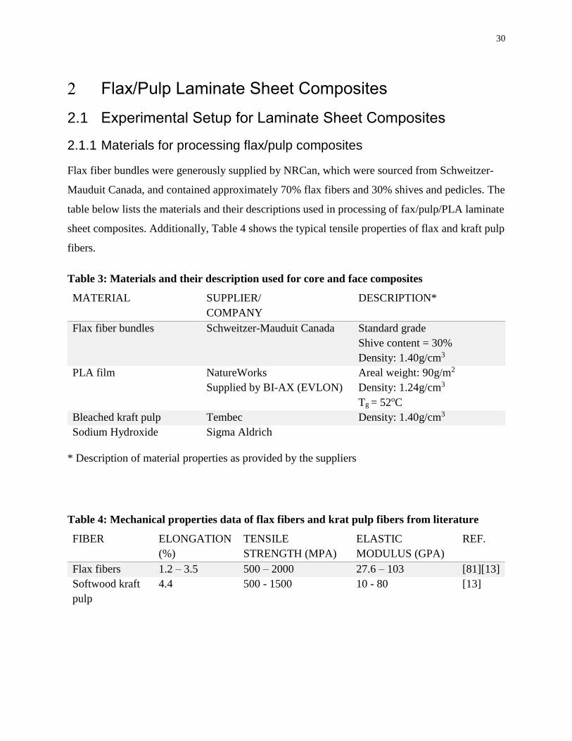
30
Flax/Pulp Laminate Sheet Composites
2.1 Experimental Setup for Laminate Sheet Composites
2.1.1 Materials for processing flax/pulp composites
Flax fiber bundles were generously supplied by NRCan, which were sourced from Schweitzer-
Mauduit Canada, and contained approximately 70% flax fibers and 30% shives and pedicles. The
table below lists the materials and their descriptions used in processing of fax/pulp/PLA laminate
sheet composites. Additionally, Table 4 shows the typical tensile properties of flax and kraft pulp
fibers.
Table 3: Materials and their description used for core and face composites
MATERIAL SUPPLIER/
COMPANY
DESCRIPTION*
Flax fiber bundles Schweitzer-Mauduit Canada Standard grade
Shive content = 30%
Density: 1.40g/cm3
PLA film NatureWorks
Supplied by BI-AX (EVLON)
Areal weight: 90g/m2
Density: 1.24g/cm3
Tg = 52oC
Bleached kraft pulp Tembec Density: 1.40g/cm3
Sodium Hydroxide Sigma Aldrich
* Description of material properties as provided by the suppliers
Table 4: Mechanical properties data of flax fibers and krat pulp fibers from literature
FIBER ELONGATION
(%)
TENSILE
STRENGTH (MPA)
ELASTIC
MODULUS (GPA)
REF.
Flax fibers 1.2 – 3.5 500 – 2000 27.6 – 103 [81][13]
Softwood kraft
pulp
4.4 500 - 1500 10 - 80 [13]
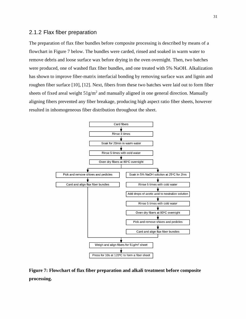
31
2.1.2 Flax fiber preparation
The preparation of flax fiber bundles before composite processing is described by means of a
flowchart in Figure 7 below. The bundles were carded, rinsed and soaked in warm water to
remove debris and loose surface wax before drying in the oven overnight. Then, two batches
were produced, one of washed flax fiber bundles, and one treated with 5% NaOH. Alkalization
has shown to improve fiber-matrix interfacial bonding by removing surface wax and lignin and
roughen fiber surface [10], [12]. Next, fibers from these two batches were laid out to form fiber
sheets of fixed areal weight 51g/m2 and manually aligned in one general direction. Manually
aligning fibers prevented any fiber breakage, producing high aspect ratio fiber sheets, however
resulted in inhomogeneous fiber distribution throughout the sheet.
Figure 7: Flowchart of flax fiber preparation and alkali treatment before composite
processing.

32
2.1.3 Processing flax/pulp sheet composites
Figure 8 describes the processing method for thin laminate sheet composites; by film stacking of
prepared fiber sheets of flax fibers and/or kraft pulp sheets followed by hot pressing. Preparation
of Flax sheets is provided in the previous section. Pulp sheets were produced following the
TAPPI standard T205 for hand sheet making at a consistent areal weight of 51g/m2. The
prepared fiber sheets, were heated overnight at 80oC and PLA sheets were heated for 2 hours at
60oC to remove moisture before hot pressing. The fiber sheets and PLA sheets were arranged in
an alternating laminate structure based on varying composition of the two fibers according to
Table 5. The flax fiber sheets were aligned with fiber direction to capture longitudinal
reinforcement of the fibers in the composite. Although, this provides a tradeoff of tensile
properties along the transverse direction, and hence, may limit performance in certain loading
conditions. The samples sets chosen had 30wt% total fiber loading and were distinguished as
flax fiber composites, FFF, pulp fiber composites, PPP, and two hybrid laminate sheet
composites of opposite configuration: two pulp sheets sandwiching one flax sheet, PFP, and vice
versa, FPF.
These assemblies were placed between two mold papers and metal plates. The composite was
hot pressed for 4min at 180oC at a pressure of 0.6MPa then cooled under pressure for 2min until
the press temperature reached 50oC. The temperature was decided based on the melt temperature
of PLA being 185oC and to prevent any matrix degradation during hot pressing [74].
Figure 8: Flax/pulp laminate sheet composite processing method
Fiber treatment
•untreated
•alkaline
Heated press long fiber sheet
•achieve grammage of 52g/m2
Film stacking with varied
•Alternating 3 fiber sheets between 4 PLA sheets
•Fiber sheets of flax and kraft fibers
Hot pressing
•T = 180oC,
•P = 0.6MPa,
•t = 4min followed by 2min cooling
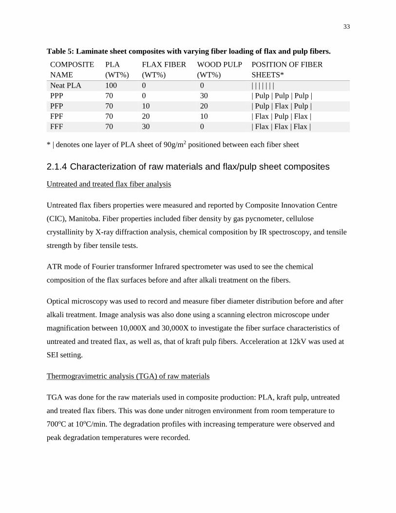
33
Table 5: Laminate sheet composites with varying fiber loading of flax and pulp fibers.
COMPOSITE
NAME
PLA
(WT%)
FLAX FIBER
(WT%)
WOOD PULP
(WT%)
POSITION OF FIBER
SHEETS*
Neat PLA 100 0 0 | | | | | | |
PPP 70 0 30 | Pulp | Pulp | Pulp |
PFP 70 10 20 | Pulp | Flax | Pulp |
FPF 70 20 10 | Flax | Pulp | Flax |
FFF 70 30 0 | Flax | Flax | Flax |
* | denotes one layer of PLA sheet of 90g/m2 positioned between each fiber sheet
2.1.4 Characterization of raw materials and flax/pulp sheet composites
Untreated and treated flax fiber analysis
Untreated flax fibers properties were measured and reported by Composite Innovation Centre
(CIC), Manitoba. Fiber properties included fiber density by gas pycnometer, cellulose
crystallinity by X-ray diffraction analysis, chemical composition by IR spectroscopy, and tensile
strength by fiber tensile tests.
ATR mode of Fourier transformer Infrared spectrometer was used to see the chemical
composition of the flax surfaces before and after alkali treatment on the fibers.
Optical microscopy was used to record and measure fiber diameter distribution before and after
alkali treatment. Image analysis was also done using a scanning electron microscope under
magnification between 10,000X and 30,000X to investigate the fiber surface characteristics of
untreated and treated flax, as well as, that of kraft pulp fibers. Acceleration at 12kV was used at
SEI setting.
Thermogravimetric analysis (TGA) of raw materials
TGA was done for the raw materials used in composite production: PLA, kraft pulp, untreated
and treated flax fibers. This was done under nitrogen environment from room temperature to
700oC at 10oC/min. The degradation profiles with increasing temperature were observed and
peak degradation temperatures were recorded.

34
Tensile Properties of laminate sheet composites
Tensile testing of laminate sheet composites was carried out following ASTM D638. Tensile
samples were cut according to Type VI specimens, with a span length of 25mm along the flax
fiber direction, and the edges were smoothened out by sanding. Eight replicates were tested for
each sample using Instron machine model 3367 at force load of 30kN at a strain rate of
2mm/min. The tensile strength, elastic modulus, and elongation at break were determined for
composites along flax fiber direction using this test. According to the stress-strain curves
generated, the tensile strength was measured as the highest stress reached by each sample before
fracture; tensile modulus was calculated as the slope of the initial linear region of the stress/strain
curve before the yield point. Additionally, elongation at break was calculated as the displacement
until fracture, divided by the initial length of the specimen.
Scanning Electron Microscopy (SEM) analysis of tensile fracture
Jeol JSM-6610LV SEM was used to study the fracture surfaces of the tensile samples. The cross-
section surfaces of tested samples were gold sputtered and fixed on to stages. Images were
obtained at fixed acceleration of 15kV and at a magnification range between 200X and 1500X.
The images were used to analyze the fracture mode and fiber-matrix interfacial characteristics.
2.2 Results and Discussion for flax/pulp sheet composites
2.2.1 Analysis of raw materials and effect of alkalization
CIC reported a detailed analysis of untreated flax fibers and is summarized below in bullet form.
More details on instruments, conditions used, and data are provided in Appendix A.
Batch included 70wt% flax fibers and 30wt% shives and pedicles (images are provided in
Figure 9).
Apparent flax fiber density measured was 1.47g/mm3.
XRD results show crystallinity index is 52.30% calculated using Segal method.
FTIR results show higher cellulose and lower wax content in fibers than in shives and
pedicles (shown in Figure 10).
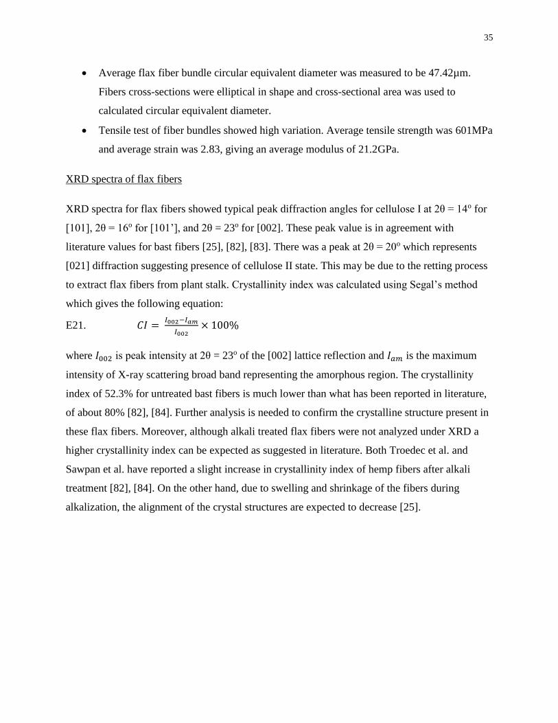
35
Average flax fiber bundle circular equivalent diameter was measured to be 47.42µm.
Fibers cross-sections were elliptical in shape and cross-sectional area was used to
calculated circular equivalent diameter.
Tensile test of fiber bundles showed high variation. Average tensile strength was 601MPa
and average strain was 2.83, giving an average modulus of 21.2GPa.
XRD spectra of flax fibers
XRD spectra for flax fibers showed typical peak diffraction angles for cellulose I at 2θ = 14o for
[101], 2θ = 16o for [101’], and 2θ = 23o for [002]. These peak value is in agreement with
literature values for bast fibers [25], [82], [83]. There was a peak at 2θ = 20o which represents
[021] diffraction suggesting presence of cellulose II state. This may be due to the retting process
to extract flax fibers from plant stalk. Crystallinity index was calculated using Segal’s method
which gives the following equation:
E21. 𝐶𝐼 = 𝐼002−𝐼𝑎𝑚
𝐼002× 100%
where 𝐼002 is peak intensity at 2θ = 23o of the [002] lattice reflection and 𝐼𝑎𝑚 is the maximum
intensity of X-ray scattering broad band representing the amorphous region. The crystallinity
index of 52.3% for untreated bast fibers is much lower than what has been reported in literature,
of about 80% [82], [84]. Further analysis is needed to confirm the crystalline structure present in
these flax fibers. Moreover, although alkali treated flax fibers were not analyzed under XRD a
higher crystallinity index can be expected as suggested in literature. Both Troedec et al. and
Sawpan et al. have reported a slight increase in crystallinity index of hemp fibers after alkali
treatment [82], [84]. On the other hand, due to swelling and shrinkage of the fibers during
alkalization, the alignment of the crystal structures are expected to decrease [25].

36
Figure 9: Flax fiber bundles as supplied (top), and separated by fibers (bottom left), shives
(bottom middle), and pedicles (bottom right), courtesy of CIC
FTIR analysis of flax fibers, shives, and pedicles
FTIR analysis showed a qualitative comparison of the chemical composition of flax fiber
bundles, shives, and pedicles. It was determined that flax fibers show highest cellulose presence,
whereas pedicles show highest oil and lignin presence. This result is expected, as the pedicles is
the region where the fiber is attached to the seed and contains high amounts of oil. Moreover,
shives and pedicles had lower fiber aspect ratio and higher dimensional variation, as evidenced
in Figure 9. Therefore, manual removal of shives and pedicles left only ~5cm flax fiber bundles
for composite processing.
Tensile strength of flax fibers
Diameters of flax fibers and fiber bundles were Tensile strength of flax fiber bundles showed a
large variation, in part, due to variation in diameter of bundles. Single fiber tests showed tensile
strength reaching 2100MPa with fiber diameter of 13μm. Data of tensile strength values are
provided in Appendix A. Fiber bundles are single fibers bonded together with lignin and pectin

37
which have lower strength and result in fibers sliding off of each other along the direction of the
uniaxial load applied. Additionally, compared with single fibers, fiber bundles have cumulative
fiber defects along the fiber bundle, as well as voids, which provide weak points for pre-mature
failure, and thus, lower tensile strength.
Figure 10: FTIR spectra of flax bundle components (fiber, shive, and pedicle) as provided
from supplier, courtesy of CIC
FTIR analysis of flax fibers before and after alkali treatment
FTIR spectra showing the chemical composition comparison of untreated and treated flax fiber
bundles is presented in Figure 11. Distinct increase in cellulose intensity peaks, specifically
1050cm-1 and 3340cm-1, show a high presence of cellulose molecules at the surface and reduced
waxes and lignin presence. Table 6 contains the peak positions and their corresponding
representation of molecular bonds and vibrations. A shift in 3330cm-1 peak to the left was
observed after alkali treatment, which indicates an increase in free –OH bonds. Although FTIR is
used as a qualitative analysis tool, this result concludes the effectiveness of alkalization of flax
fibers to decrease the presence of noncellulosic materials on the fiber surfaces and allow an
increase in active hydroxyl sites. This will provide higher hydrogen bonding sites between flax
fibers and PLA matrix for improved fiber-matrix interaction [10], [80]. Although, increased
accessible –OH groups suggest increased polar surface energy and reduced fiber wettability [36].
This is evident in biocomposite system of flax fibers and unsaturated polyester matrix, as

38
reported by Dhakal et al. [36]. On the other hand, since PLA matrix shows some affinity towards
hydrogen bonding with natural fibers, due to presence of polar oxygen atoms [74]. Therefore, it
can be assumed there may be some degree of improvement in fiber-matrix interfacial bonding
post-alkali treatment of fibers.
Figure 11: FTIR spectra of untreated and alkali treated flax fibers of wavelength range 600
to 4000µm
Table 6: Peak positions of FTIR spectra of flax fibers and their corresponding
representation of molecular bonds and vibrations
PEAK POSITION (CM-1) MOLECULAR
BOND/VIBRATION
TENTATIVE
ASSIGNMENT
3300 - 3340 O-H stretch Cellulose, hemicellulose
2850 - 2920 CH2 (a)symmetric stretch Waxes/oils, cellulose
1500 - 1500 C=C aromatic symmetric stretch Lignin
1310 - 1320 CH2 rock Cellulose
1020 - 1050 C-OH stretch Cellulose
Optical microscopy analysis of flax fibers before and after treatment
Optical microscopy was used to capture images of fiber bundles before and after alkali treatment.
Then, ImageJ analysis software tool was used to measure and record fiber diameters of
approximately 300 fibers each batch. Fiber diameter distribution histogram of flax fibers before
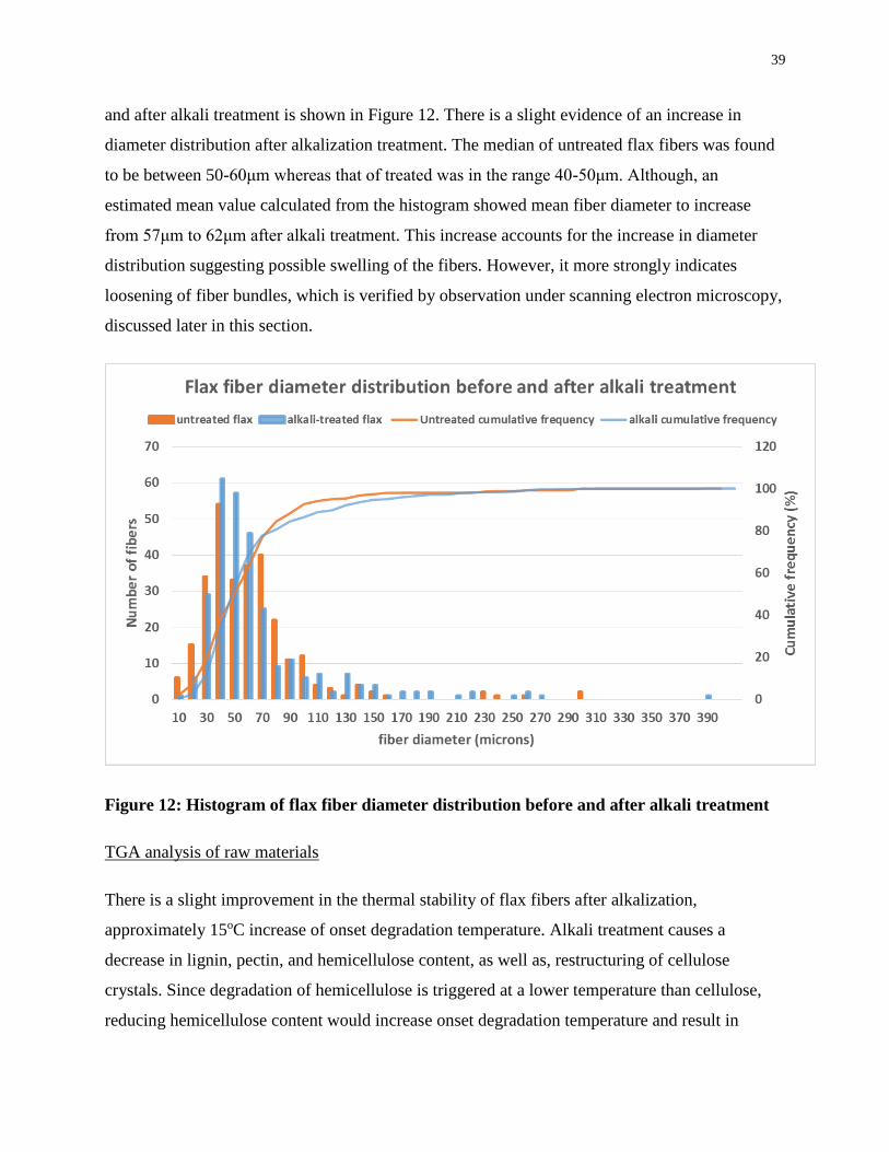
39
and after alkali treatment is shown in Figure 12. There is a slight evidence of an increase in
diameter distribution after alkalization treatment. The median of untreated flax fibers was found
to be between 50-60μm whereas that of treated was in the range 40-50μm. Although, an
estimated mean value calculated from the histogram showed mean fiber diameter to increase
from 57μm to 62μm after alkali treatment. This increase accounts for the increase in diameter
distribution suggesting possible swelling of the fibers. However, it more strongly indicates
loosening of fiber bundles, which is verified by observation under scanning electron microscopy,
discussed later in this section.
Figure 12: Histogram of flax fiber diameter distribution before and after alkali treatment
TGA analysis of raw materials
There is a slight improvement in the thermal stability of flax fibers after alkalization,
approximately 15oC increase of onset degradation temperature. Alkali treatment causes a
decrease in lignin, pectin, and hemicellulose content, as well as, restructuring of cellulose
crystals. Since degradation of hemicellulose is triggered at a lower temperature than cellulose,
reducing hemicellulose content would increase onset degradation temperature and result in
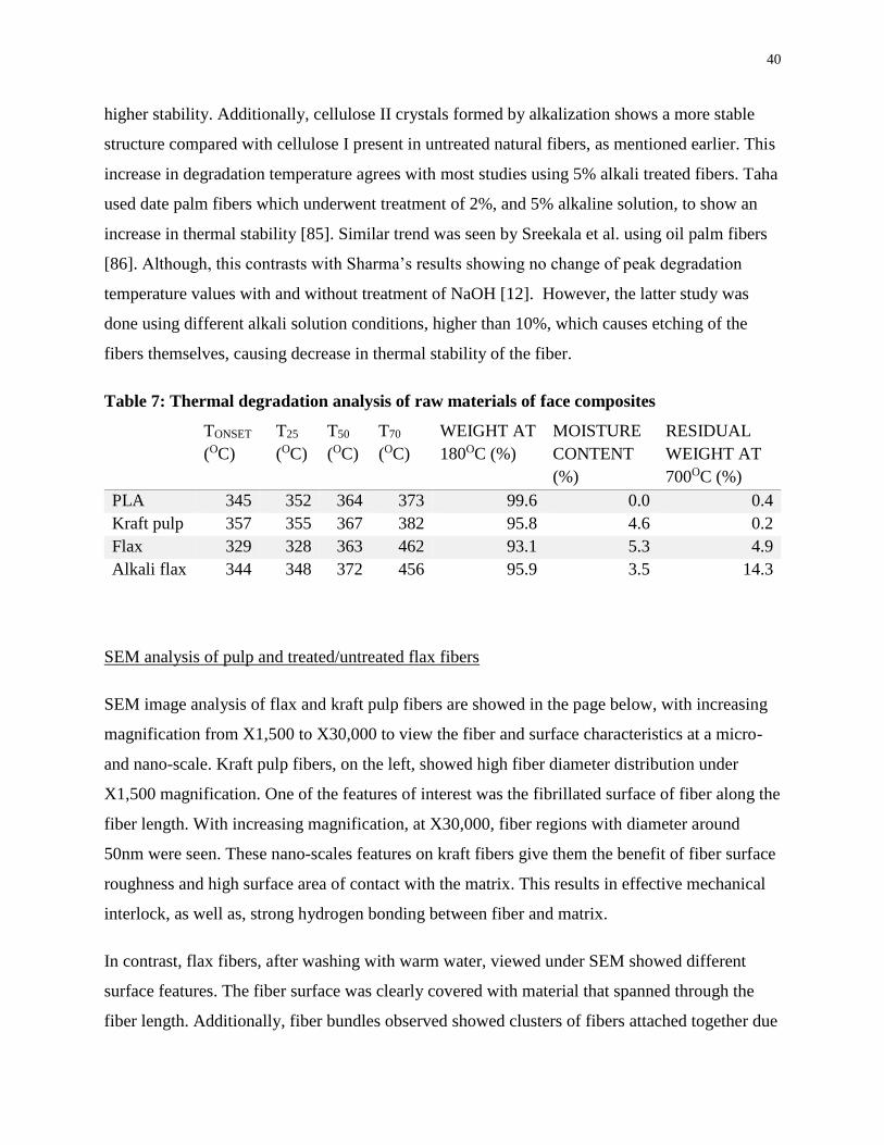
40
higher stability. Additionally, cellulose II crystals formed by alkalization shows a more stable
structure compared with cellulose I present in untreated natural fibers, as mentioned earlier. This
increase in degradation temperature agrees with most studies using 5% alkali treated fibers. Taha
used date palm fibers which underwent treatment of 2%, and 5% alkaline solution, to show an
increase in thermal stability [85]. Similar trend was seen by Sreekala et al. using oil palm fibers
[86]. Although, this contrasts with Sharma’s results showing no change of peak degradation
temperature values with and without treatment of NaOH [12]. However, the latter study was
done using different alkali solution conditions, higher than 10%, which causes etching of the
fibers themselves, causing decrease in thermal stability of the fiber.
Table 7: Thermal degradation analysis of raw materials of face composites
TONSET
(OC)
T25
(OC)
T50
(OC)
T70
(OC)
WEIGHT AT
180OC (%)
MOISTURE
CONTENT
(%)
RESIDUAL
WEIGHT AT
700OC (%)
PLA 345 352 364 373 99.6 0.0 0.4
Kraft pulp 357 355 367 382 95.8 4.6 0.2
Flax 329 328 363 462 93.1 5.3 4.9
Alkali flax 344 348 372 456 95.9 3.5 14.3
SEM analysis of pulp and treated/untreated flax fibers
SEM image analysis of flax and kraft pulp fibers are showed in the page below, with increasing
magnification from X1,500 to X30,000 to view the fiber and surface characteristics at a micro-
and nano-scale. Kraft pulp fibers, on the left, showed high fiber diameter distribution under
X1,500 magnification. One of the features of interest was the fibrillated surface of fiber along the
fiber length. With increasing magnification, at X30,000, fiber regions with diameter around
50nm were seen. These nano-scales features on kraft fibers give them the benefit of fiber surface
roughness and high surface area of contact with the matrix. This results in effective mechanical
interlock, as well as, strong hydrogen bonding between fiber and matrix.
In contrast, flax fibers, after washing with warm water, viewed under SEM showed different
surface features. The fiber surface was clearly covered with material that spanned through the
fiber length. Additionally, fiber bundles observed showed clusters of fibers attached together due
41
to presence of this material. This material was identified as a combination of wax, lignin, and
pectin, as identified using FTIR spectra. Under high magnification, the surface was viewed to be
smooth. Comparatively, alkali treated flax fibers showed cleaner flax surfaces, with lesser
amounts of material covering the surface. The treatment uncovers fiber features such as elbows,
as well as, increases cellulose exposure signifying higher hydroxyl groups for improved fiber-
matrix bonding. X15,000 and X30,000 showed no surface etching or roughness after alkali
treatment resulting in smooth fiber surface. Although it is suggested by some papers that fiber
surface roughness increases fiber-matrix adhesion by promoting mechanical interlock, most
papers criticize the tradeoff of loss in fiber strength and modulus with increased roughness.
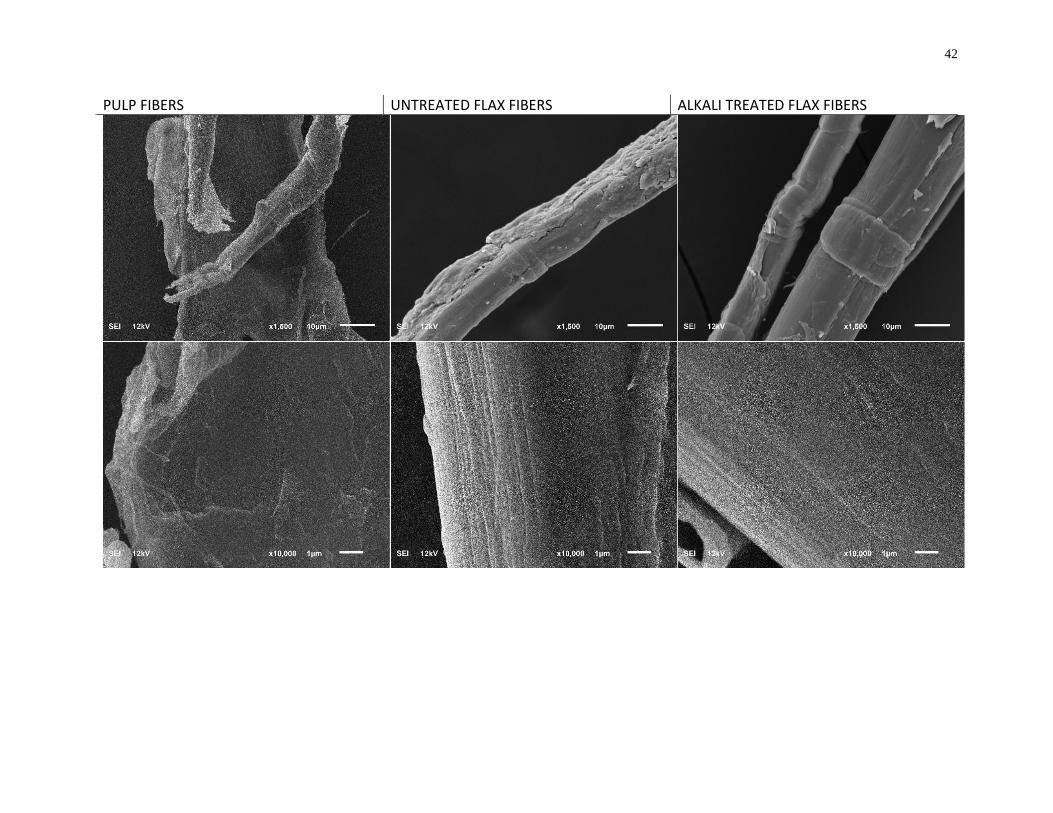
42
PULP FIBERS UNTREATED FLAX FIBERS ALKALI TREATED FLAX FIBERS

43
Figure 13: SEM images of kraft pulp fibers (left), untreated flax fibers (middle) and alkali-treated flax fibers (right) with
increasing magnification from top to bottom X1500, X10000, X30000, respectively.
44
2.2.2 Tensile properties of flax/pulp laminate sheet composites
Tensile strength and modulus values were measured using the generated load-deflection curves
from tensile tests of laminate sheet composites. Samples of neat PLA, and 30wt% pulp
composites, PPP, 30wt% untreated and treated flax composites, FFF and aFFF, and hybrid
flax/pulp composites of ratio 10wt%/20wt%, PFP, and 20wt%/10wt%, FPF, were made
following the same processing method as described in section 2.1.3. All composites were made
to achieve equal density and thickness of ~1.24g/cm3 and 0.45mm, respectively. The load-
deflection curves for PLA, PPP, FFF and aFFF are provided in Appendix B. Figure 14 and
Figure 15 show tensile strength and modulus of all composite samples.
Neat polymer, pulp/PLA and flax/PLA composites
Tensile results of neat PLA, undergone hot pressing, showed lower strength and modulus than
what has been reported by other studies, at 47.2MPa and 1.5GPa, respectively. This is partly due
to hot pressing conditions that were chosen. These conditions were selected to prevent biofiber
degradation during composite processing; however, optimization study of hot pressing was not
carried out. A lower pressure may result in air bubbles and micro-voids, which would reduce its
mechanical properties. Press time and cooling rate defines the polymer crystallinity and
influence tensile modulus. Nonetheless, a significant improvement in tensile strength and
modulus of PLA sheets were achieved with addition of 30wt% fiber content, presenting
successful reinforcement of the PLA matrix.
Pulp handsheets were made using standard Tappi method to produce uniform network of short
pulp fibers. Therefore, the strength and modulus of pulp/PLA composites showed a significant
increase from neat PLA, to 62.5MPa and 2.6GPa, respectively. Comparing pulp fiber composites
to flax fiber composites, there was a 20% and 38% increase in strength and modulus. This
positive reinforcing effect could be further increased by improving upon the flax fiber sheet
making method of manual alignment of flax fiber bundles. The manual method resulted in
inhomogeneity, uneven dispersion of fibers, and closely packed fiber bundles. By mitigating
these features of flax sheets, a much higher reinforcing effect is predicted than that of what is
achieved in this study.
45
Flax/Pulp/PLA hybrid laminates
A positive hybrid effect is noticed for tensile modulus of PFP and FPF from their constituent
non-hybrid composites PPP and FFF. This hybrid effect is discussed further in section below. On
the other hand, a negative hybrid effect is distinguished for the tensile strength of hybrid
composites. This contrasted with the positive effect shown by modulus, and can be explained by
the difference in influential factors that govern tensile strength and modulus of fiber reinforced
composites. Tensile strength and modulus are both attributed to fiber volume fraction, fiber
microstructure, aspect ratio, and presence of defects; however, the former is also strongly
influenced by fiber-matrix interfacial bonding [53], [87]. Flax fibers show poorer interfacial
bonding with PLA matrix as opposed to wood pulp fibers, which is evidenced in literature [28],
[38], [46]. Also, fiber-matrix adhesion characteristics are discussed in more detail in the next
section. Due to greater number of weak fiber-matrix bonding regions, as well as, regions of large
flax fiber clusters with incomplete wetting, there is an increase in stress concentrating sites per
cross-sectional area with increasing content of flax fibers. Therefore, flax fibers do not provide a
synergistic effect in improving flax/pulp composite tensile strength.
It has been stated in literature that fiber-matrix interfacial bonding has little to no effect on
young’s modulus [13]. Although, stronger fiber-matrix interfacial bonding implies more
pronounced levels of stress transfer, leading to fibers undergoing equivalent elastic loading to
matrix. Consequently, fiber modulus is utilized in carrying load which increases in overall
modulus.
Furthermore, no significant change is observed between tensile properties of PFP and FPF
because of compensation between pulp-PLA adhesion and effective fiber bundle stiffness and
elasticity of flax fibers when the ratios of flax/pulp are reversed.

46
Figure 14: Tensile strength of flax/pulp/PLA laminate sheet composites with and without
alkali treatment of flax fibers
Figure 15: Tensile modulus of flax/pulp/PLA laminate sheet composites with and without
alkali treatment of flax fibers

47
Influence of alkali-treated flax on flax/pulp/PLA composites
Alkalization of flax fibers showed little to no effect in overall composite properties. Literature
has shown a spectrum of results, which concludes that alkalization affects various fiber
characteristics. These include fiber microstructure, crystallinity, fibrillar alignment, chemical
composition, and surface characteristics [10], [24], [29]. Using optimum alkali treatment
conditions are, therefore, vital in achieving desirable end properties. As suggested by literature
and evidenced in the fiber analyses in the previous sections, the treatment conditions used in this
study caused reduced fiber strength and modulus with increased fiber-matrix interfacial bonding.
This trade-off of desirable fiber characteristics resulted in insignificant improvements compared
with untreated flax fiber composites.
Mechanical behavior of alkali treated fibers is directly influenced by the change in fiber
microstructure and in chemical composition, influencing a change in strength and modulus.
Alkali treated flax composites under uniaxial load, undergo slippage between cellulose mirco-
fibrils to align along the loading direction, instead of elastic loading of the fibers. This slippage is
caused by the absence of hemicellulose and lignin which function to keep the micro-fibrillar
structure intact. This results in deformation at low strains [32], [33]. Hence, the lower fiber
modulus and strength reduces that of the composites. Although, the overall elongation at break
improves, as the composite can carry more strain before ductile failure. Additionally, relatively
weak interfacial bonding provides an increase in overall toughness and impact properties [32].
Suizu et al. shows stress-strain curve for mercerized ramie fiber composites starting its nonlinear
region at 1% strain and failure at 6%, as opposed to showing a linear curve of untreated fiber
composites and a brittle fracture at 2% [32]
On the other hand, with keeping the fibers taught during alkali treatment, fiber strength and
modulus show improvements which also reflect in their corresponding composites [24], [88].
Kim et al. shows a significant increase in tensile strength and Young’s modulus with increasing
degree of fiber tension during 2hr mercerization treatment [31]. 50g/fiber was the optimum load
determined by the authors to achieve best sisal fiber tensile strength and modulus, 35% and
110% higher than that of untreated, respectively, with 39% decrease in strain. In conculsion, Kim
determined increase in fiber tensile strength and modulus to be due to two reasons: increase in

48
cellulose content, and decrease in microfibrillar angle. Although there was an observed increase
in moisture content, which is undesirable [31].
2.2.3 Fracture morphology flax/pulp laminate sheet composites
Fracture surface images were captured using optical microscopy and are provided in Figure 16.
Fracture of PPP was ductile with high plastic deformation shown as relatively clean cut on the
fracture surface and elongation creases, orthogonal to the loading direction, on the faces of the
composite sheets. Alternatively, FFF and a_FFF, showed jagged surface fracture exhibiting a
brittle failure. Especially, thick fiber bundles acted as stress concentrating sites, which reflected
in lower than expected tensile properties of the composite. To reduce the effect of inhomogeneity
of fiber distribution, processing method needs to be revisited. Subsequently, failures of the
hybrid composites showed intermediary failure characteristics; PFP showed slightly higher
ductile failure compared with FPF, showing a cleaner cut at the fracture surface.
SEM analysis was also performed on flax/pulp composites of untreated and alkali-treated flax
fibers to see fracture surfaces of tensile tests. Figure 17 (a) shows fracture surface of PPP and
strong fiber-matrix interfacial bonding resulting in failure by fiber fracture. The structure shows
well dispersed pulp fibers within the matrix. Conversely, flax fiber composites, FFF, in Figure 17
(b), show clear signs of low fiber-matrix bonding with clear gaps between fiber and matrix as
well as smooth fiber surfaces. Additionally, fiber pull-out is viewed as the primary failure mode
with evidence of weak interfacial bonding and closely packed fiber bundles. This observation is
consistent with all composites with untreated flax fiber loading, Figure 17 (d), (f), (h), (j). The
observed weak untreated flax-PLA adhesion and incomplete wetting regions justifies the low
reinforcing effect of flax fibers in all flax and hybrid composite samples. Moreover, premature
failure of composites are evident because of low fiber alignment causing crack propagation along
weak fiber bundle-matrix interface.
On the other hand, alkali treated flax fiber composites and their hybrids, in Figure 17 (c), (e), (g),
(i), (k) show improved fiber-matrix interfacial adhesion. Failure mode is evidenced to be a
combination of fiber pull-out and fiber fracture, and there are fiber clusters still present acting as
stress concentrating sites. The fiber surfaces, although, show some evidence of matrix residue
after fracture which suggests good fiber-matrix bonding. These imaging analysis confirm the
results and discussions addressed in the previous sections.
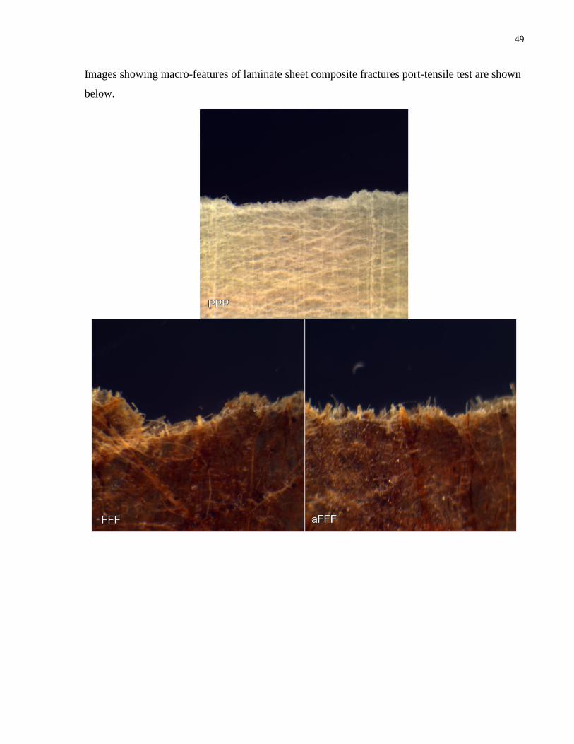
49
Images showing macro-features of laminate sheet composite fractures port-tensile test are shown
below.

50
Figure 16: Optical microscopy images of tensile fracture surfaces of flax/pulp/PLA
laminate sheet composites
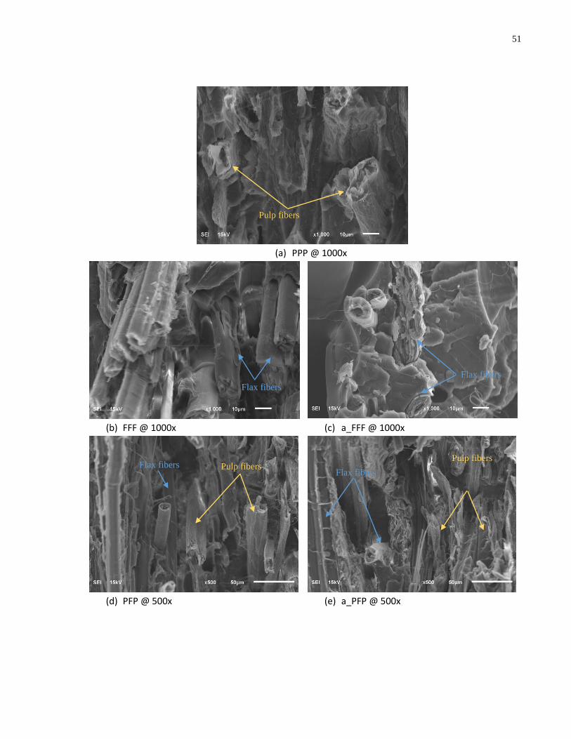
51
(a) PPP @ 1000x
(b) FFF @ 1000x (c) a_FFF @ 1000x
(d) PFP @ 500x (e) a_PFP @ 500x
Flax fibers Pulp fibers Pulp fibers
Flax fibers
Flax fibers
Flax fibers
Pulp fibers

52
(f) PFP @ 1000x (g) a_PFP @ 1000x
(h) FPF @ 500x (i) a_FPF @ 500x
(j) FPF @ 1000x (k) a_FPF @ 1000x
Figure 17: SEM images of tensile test fracture surfaces of flax/pulp/PLA laminate sheet
composites (a) – (k); yellow arrows point to pulp fibers and blue arrows point to flax fibers.
Pulp fibers
Pulp fibers
Pulp fibers Pulp fibers
Flax fibers
Flax fibers
Flax fibers
Flax fibers
Pulp fibers
Pulp fibers
Flax fibers
Flax fibers

53
2.3 HROM and Halpin Tsai for Hybrid Laminate Sheet Composites
Mathematical mechanical models have been established for understanding underlying factors and
parameters that influence composite mechanical properties and predicting mechanical properties
with varying factors without having to produce and test materials. HROM and Halpin-Tsai
equations, as provided in 1.2.4, were used to predict the theoretical trend of hybridization of
flax/pulp fiber composites. As well as, an adjusted Halpin-Tsai model to account for fiber
orientation of flax and pulp fiber laminates, separately, as illustrated in Figure 18. Since flax
fibers were aligned manually towards direction of loading, only 𝐸𝑙𝑜𝑛𝑔 is considered, whereas for
randomly oriented pulp fiber hand sheets, 𝐸𝑟𝑎𝑛𝑑𝑜𝑚 is considered.
HROM equation used:
E22. 𝐸𝐻𝑅𝑂𝑀 = 𝐸𝑓𝑐𝑉𝑓 + 𝐸𝑝𝑐𝑉𝑝
Halpin-Tsai equation used, incorporating 3:5 ratio for short planar randomly oriented fibers:
E23. 𝐸𝐻−𝑇 =3
8[𝐸𝑚 (
1+𝜉𝑓,𝑙𝜂𝑓,𝑙𝑉𝑓
1−𝜂𝑓,𝑙𝑉𝑓) + 𝐸𝑚 (
1+𝜉𝑝,𝑙𝜂𝑝,𝑙𝑉𝑝
1−𝜂𝑝,𝑙𝑉𝑝)] +
5
8[𝐸𝑚 (
1+2𝜂𝑓,𝑡𝑉𝑓
1−𝜂𝑓,𝑡𝑉𝑓) + 𝐸𝑚 (
1+2𝜂𝑝,𝑡𝑉𝑝
1−𝜂𝑝,𝑡𝑉𝑝)]
Adjusted Halpin-Tsai equation used, following the schematic provided in Figure 18:
E24. 𝐸𝑎𝑑𝑗𝐻−𝑇 = 𝐸𝑓,𝑙 + 𝐸𝑝,𝑟
Where 𝐸𝑓,𝑙 is modulus of flax fiber composite in longitudinal direction, given as:
E25. 𝐸𝑓,𝑙 = 𝐸𝑚 (1+𝜉𝑓,𝑙𝜂𝑓,𝑙𝑉𝑓
1−𝜂𝑓,𝑙𝑉𝑓)
E26. 𝜂𝑓,𝑙 =(
𝐸𝑓𝐸𝑚
⁄ )−1
(𝐸𝑓
𝐸𝑚⁄ )+𝜉𝑓,𝑙
And, 𝐸𝑝,𝑟 is the modulus of pulp fiber composite with randomly oriented fibers, given as:

54
E27. 𝐸𝑝,𝑟 = 3
8𝐸𝑝,𝑙 +
5
8𝐸𝑝,𝑡
E28. 𝐸𝑝,𝑙 = 𝐸𝑚 (1+𝜉𝑝,𝑙𝜂𝑝,𝑙𝑉𝑝
1−𝜂𝑝,𝑙𝑉𝑝)
E29. 𝐸𝑝.𝑡 = 𝐸𝑚 (1+2𝜂𝑝,𝑡𝑉𝑝
1−𝜂𝑝,𝑡𝑉𝑝)
E30. 𝜂𝑝,𝑙 =(
𝐸𝑝𝐸𝑚
⁄ )−1
(𝐸𝑝
𝐸𝑚⁄ )+𝜉𝑝,𝑙
E31. 𝜂𝑝,𝑡 =(
𝐸𝑝E𝑚
⁄ )−1
(E𝑝
E𝑚⁄ )+𝜉𝑝,𝑡
Therefore, the adjusted Halpin-Tsai equation can be written as:
E32. 𝐸𝑎𝑑𝑗𝐻−𝑇 = 𝐸𝑚 (1+𝜉𝑓,𝑙𝜂𝑓,𝑙𝑉𝑓
1−𝜂𝑓,𝑙𝑉𝑓) +
3
8[𝐸𝑚 (
1+𝜉𝑝,𝑙𝜂𝑝,𝑙𝑉𝑝
1−𝜂𝑝,𝑙𝑉𝑝)] +
5
8[𝐸𝑚 (
1+𝜉𝑝,𝑡𝜂𝑝,𝑡𝑉𝑝
1−𝜂𝑝,𝑡𝑉𝑝)]
Where suffixes f and p are designated for flax and pulp composites, respectively, and suffixes l
and t represent longitudinal or transverse direction, respectively.
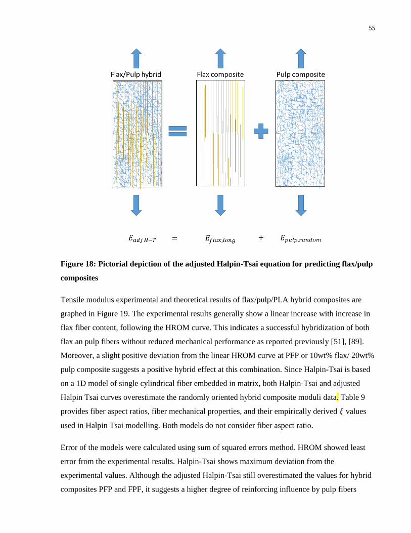
55
Figure 18: Pictorial depiction of the adjusted Halpin-Tsai equation for predicting flax/pulp
composites
Tensile modulus experimental and theoretical results of flax/pulp/PLA hybrid composites are
graphed in Figure 19. The experimental results generally show a linear increase with increase in
flax fiber content, following the HROM curve. This indicates a successful hybridization of both
flax an pulp fibers without reduced mechanical performance as reported previously [51], [89].
Moreover, a slight positive deviation from the linear HROM curve at PFP or 10wt% flax/ 20wt%
pulp composite suggests a positive hybrid effect at this combination. Since Halpin-Tsai is based
on a 1D model of single cylindrical fiber embedded in matrix, both Halpin-Tsai and adjusted
Halpin Tsai curves overestimate the randomly oriented hybrid composite moduli data. Table 9
provides fiber aspect ratios, fiber mechanical properties, and their empirically derived 𝜉 values
used in Halpin Tsai modelling. Both models do not consider fiber aspect ratio.
Error of the models were calculated using sum of squared errors method. HROM showed least
error from the experimental results. Halpin-Tsai shows maximum deviation from the
experimental values. Although the adjusted Halpin-Tsai still overestimated the values for hybrid
composites PFP and FPF, it suggests a higher degree of reinforcing influence by pulp fibers
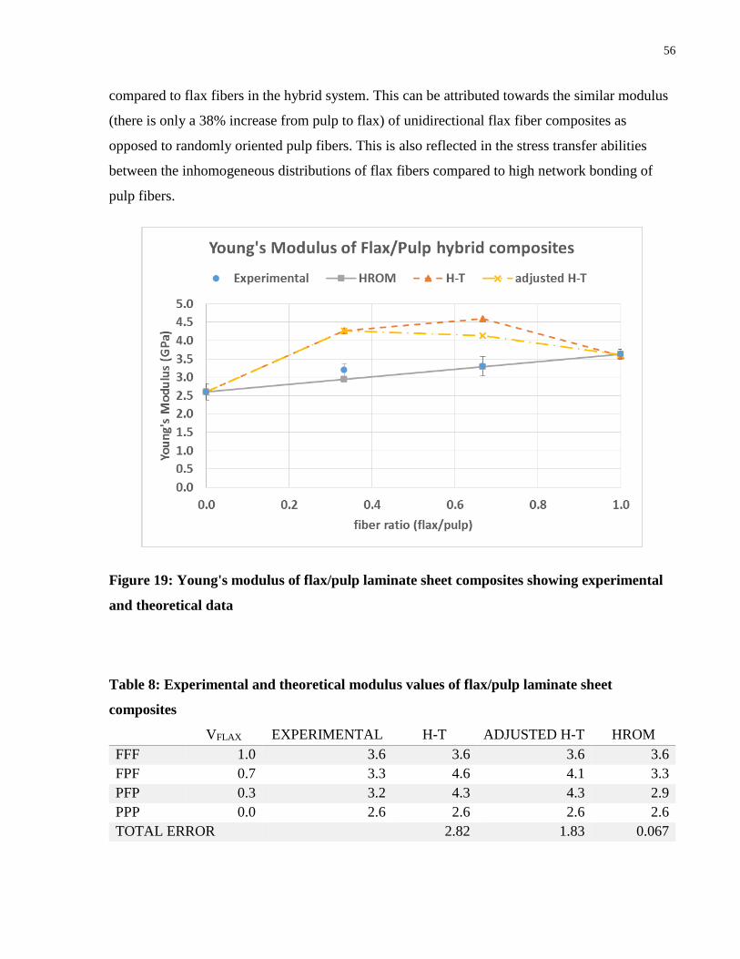
56
compared to flax fibers in the hybrid system. This can be attributed towards the similar modulus
(there is only a 38% increase from pulp to flax) of unidirectional flax fiber composites as
opposed to randomly oriented pulp fibers. This is also reflected in the stress transfer abilities
between the inhomogeneous distributions of flax fibers compared to high network bonding of
pulp fibers.
Figure 19: Young's modulus of flax/pulp laminate sheet composites showing experimental
and theoretical data
Table 8: Experimental and theoretical modulus values of flax/pulp laminate sheet
composites
VFLAX EXPERIMENTAL H-T ADJUSTED H-T HROM
FFF 1.0 3.6 3.6 3.6 3.6
FPF 0.7 3.3 4.6 4.1 3.3
PFP 0.3 3.2 4.3 4.3 2.9
PPP 0.0 2.6 2.6 2.6 2.6
TOTAL ERROR 2.82 1.83 0.067

57
Table 9: Fiber values and Halpin-Tsai parameters used for modelling composite modulus
H-T ADJ H-T
L
(mm)
D
(mm)
L/D Lc Ɨ
(mm)
𝜎𝑓
(MPa)
𝐸𝑓
(GPa)
𝜉𝑙𝑜𝑛𝑔 𝜉𝑡𝑟𝑎𝑛𝑠 𝜉𝑙𝑜𝑛𝑔 𝜉𝑡𝑟𝑎𝑛𝑠
Flax 50 0.047 1,063 1.41 601 21.2 9.5 2 4.2 -
Kraft 1.24* 0.025* 49.6 0.675 540* 10 2 2 2 2
Ɨ Interfacial shear strength for pulp was assumed 10MPa. The range provided in literature is 4 – 15MPa
between natural fibers and PLA matrix [3], [83], [90].
* kraft pulp fiber values taken from literature [74].
2.4 Summary
Untreated flax fiber bundles were analyzed to show about 53% cellulose crystallinity with
high amorphous structure, and tensile strength and modulus of 601 MPa and 21GPa,
respectively.
Alkali treatment of flax fibers increased flax fiber cellulose content and peak degradation
temperature, however, showed a slight increase in mean fiber diameter.
Tensile strength and modulus in the longitudinal direction were significantly improved
for pulp fiber and flax fiber reinforced PLA composites with 30wt% fiber loading.
Hybrid composites showed intermediary properties with a slight positive hybrid effect of
tensile modulus at 10wt%flax / 20wt% pulp fiber ratio and was confirmed by HROM
curve. Halpin-Tsai equations were also used, however showed overestimation of the data.
SEM images of tensile sample fracture surfaces confirmed fiber breakage for pulp
fiber/PLA composites due to high fiber-matrix interfacial bonding, and fiber pull-out for
flax fiber/PLA composites due to weak fiber-matrix interfacial bonding. Alkali-treated
flax fiber/PLA composites showed a combination of fiber breakage and pull-out as the
interfacial adhesion improved.

58
Flax/Pulp Fibrous Core and Lightweight Sandwich structure
3.1 Experimental Setup for Core Composite and Sandwich Panel
3.1.1 Processing of core composites and sandwich panels
Flax fibers and kraft pulp fibers were the same as those of laminate sheet composites and details
are provided in section 4.1.1. PLA fibers used for core processing were supplied by
NatureWorks, grade 6202D. Provided description for PLA fibers include: glass-transition
temperature of 58oC, average fiber length and diameter of 6mm and 12μm, respectively, and a
density of 1.24g/cm3.
Core composites were made using wet-laid process. Figure 20 and Figure 21 illustrate the
processing steps to making the core composites of varying fiber ratios of flax and pulp fibers.
The total fiber loading was kept constant at 50wt% with 50wt% being PLA matrix. Samples
were named based on flax: pulp fiber ratio; 0F signifies 0:50 ratio with 50wt% PLA matrix.
Similarly, sample sets of 0F, 10F, 25F and 50F were produced of 0wt%, 10wt%, 25wt% and
50wt% of flax fiber loading were produced. Additionally, core with 10wt% of alkali treated flax
fiber loading, 10F_a, was also produced for comparison.
Pulp fibers were weighed and soaked in water for about 4hrs. Meanwhile, weighed flax were cut
to 0.5cm long fibers and mixed with PLA and pulp fibers. The mixture was rigorously mixed
using standard pulp disintegrator for 10min at 3000rpm to produce a dense slurry of 0.02g/mL
consistency. The slurry was drained using a mold lined with a fine mesh to retain the solid
content. Excess water was pushed out to form a fiber mat of area 15cm x 20cm. Three replicate
mats of each sample set were produced under the same conditions and oven-dried overnight at
80oC. The fiber mats were then hot pressed under controlled thickness of 9.5cm at 175oC for
3min followed by cold pressing to prevent thermal expansion.
Consequently, sandwich panels were made by hot pressing the face and core composites, as
presented in Figure 22, showing the best tensile and compression properties, respectively.
Therefore, FFF face composites of 30wt% untreated flax fibers, of thickness and density 0.45mm
and 1.24g/cm3, respectively were chosen along with 0F and 10F core composites of thickness
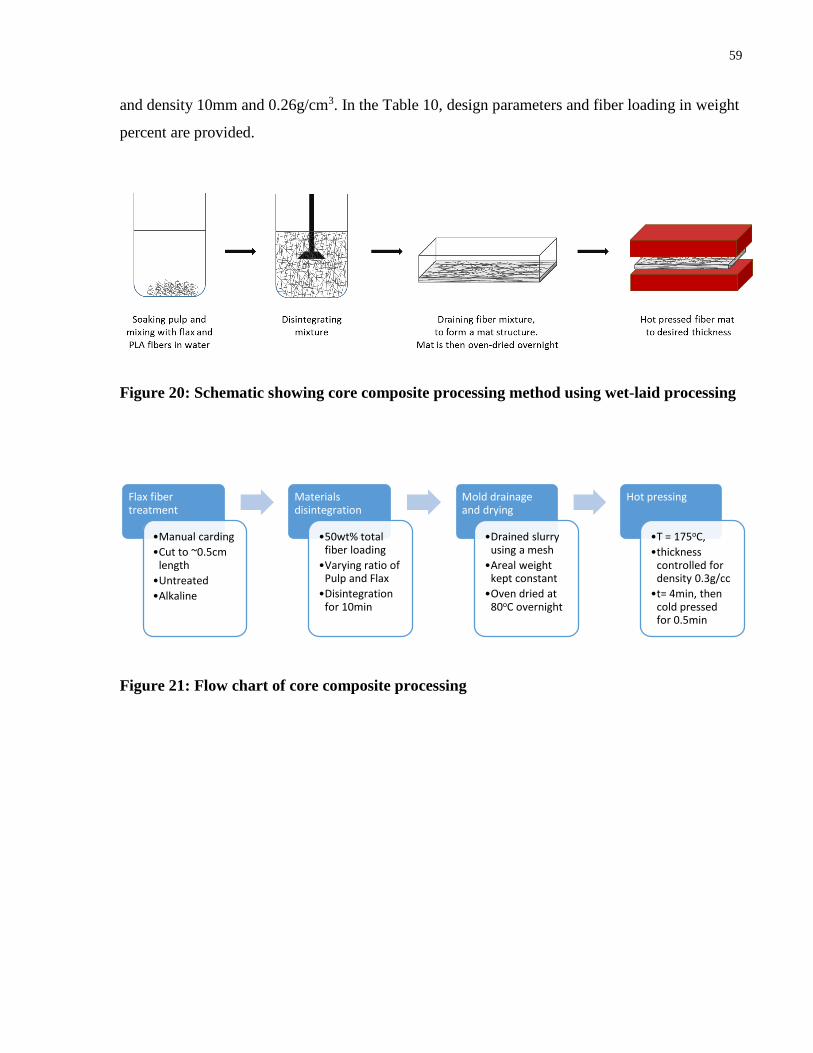
59
and density 10mm and 0.26g/cm3. In the Table 10, design parameters and fiber loading in weight
percent are provided.
Figure 20: Schematic showing core composite processing method using wet-laid processing
Figure 21: Flow chart of core composite processing
Flax fiber treatment
•Manual carding
•Cut to ~0.5cm length
•Untreated
•Alkaline
Materials disintegration
•50wt% total fiber loading
•Varying ratio of Pulp and Flax
•Disintegration for 10min
Mold drainage and drying
•Drained slurry using a mesh
•Areal weight kept constant
•Oven dried at 80oC overnight
Hot pressing
•T = 175oC,
•thickness controlled for density 0.3g/cc
•t= 4min, then cold pressed for 0.5min

60
Figure 22: Schematic showing hot pressing step of sandwich panels and their component
thicknesses and densities
Table 10: Sandwich panel components and fiber loading in weight percent
SAMPLE FACE
TYPE
CORE
TYPE
c/t
(mm/
mm)
TOTAL
DENSITY
(g/cm3)
SAMPLE
DIMENSIONS
(cm3)
TOTAL
FIBER
LOADING
(wt%)
FLAX
FIBER
LOADING
(wt%)
FFF0F FFF 0F 20 0.352
±0.03
14 x 2.5 x 1.1 43.9 8.8
FFF10F FFF 10F 20 0.352
±0.03
14 x 2.5 x 1.1 43.9 15.8
3.1.2 Characterization of core composites and sandwich panels
Core Compression Test
Compression testing was done on the core composites following ASTM D1621 standard for
semi-rigid cellular plastics using the Universal Instron machine. Four replicates were made by
cutting and sanding the core composite mats to 5cm x 5cm specimens. The test speed was set at
2mm/min. Load-deflection curve was recorded to calculate compression strength and modulus.
Sandwich Flexural Test
Sandwich panel bending test was carried out according to ASTM D7250 using 3-point bend
loading configuration as a span length of 50mm. The samples were cut and sanded to achieve
14cm x 2.5cm with a constant thickness of 11cm. Samples sizes were determined using the
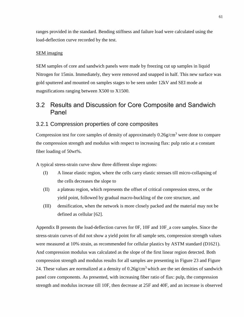
61
ranges provided in the standard. Bending stiffness and failure load were calculated using the
load-deflection curve recorded by the test.
SEM imaging
SEM samples of core and sandwich panels were made by freezing cut up samples in liquid
Nitrogen for 15min. Immediately, they were removed and snapped in half. This new surface was
gold sputtered and mounted on samples stages to be seen under 12kV and SEI mode at
magnifications ranging between X500 to X1500.
3.2 Results and Discussion for Core Composite and Sandwich Panel
3.2.1 Compression properties of core composites
Compression test for core samples of density of approximately 0.26g/cm3 were done to compare
the compression strength and modulus with respect to increasing flax: pulp ratio at a constant
fiber loading of 50wt%.
A typical stress-strain curve show three different slope regions:
(I) A linear elastic region, where the cells carry elastic stresses till micro-collapsing of
the cells decreases the slope to
(II) a plateau region, which represents the offset of critical compression stress, or the
yield point, followed by gradual macro-buckling of the core structure, and
(III) densification, when the network is more closely packed and the material may not be
defined as cellular [62].
Appendix B presents the load-deflection curves for 0F, 10F and 10F_a core samples. Since the
stress-strain curves of did not show a yield point for all sample sets, compression strength values
were measured at 10% strain, as recommended for cellular plastics by ASTM standard (D1621).
And compression modulus was calculated as the slope of the first linear region detected. Both
compression strength and modulus results for all samples are presenting in Figure 23 and Figure
24. These values are normalized at a density of 0.26g/cm3 which are the set densities of sandwich
panel core components. As presented, with increasing fiber ratio of flax: pulp, the compression
strength and modulus increase till 10F, then decrease at 25F and 40F, and an increase is observed
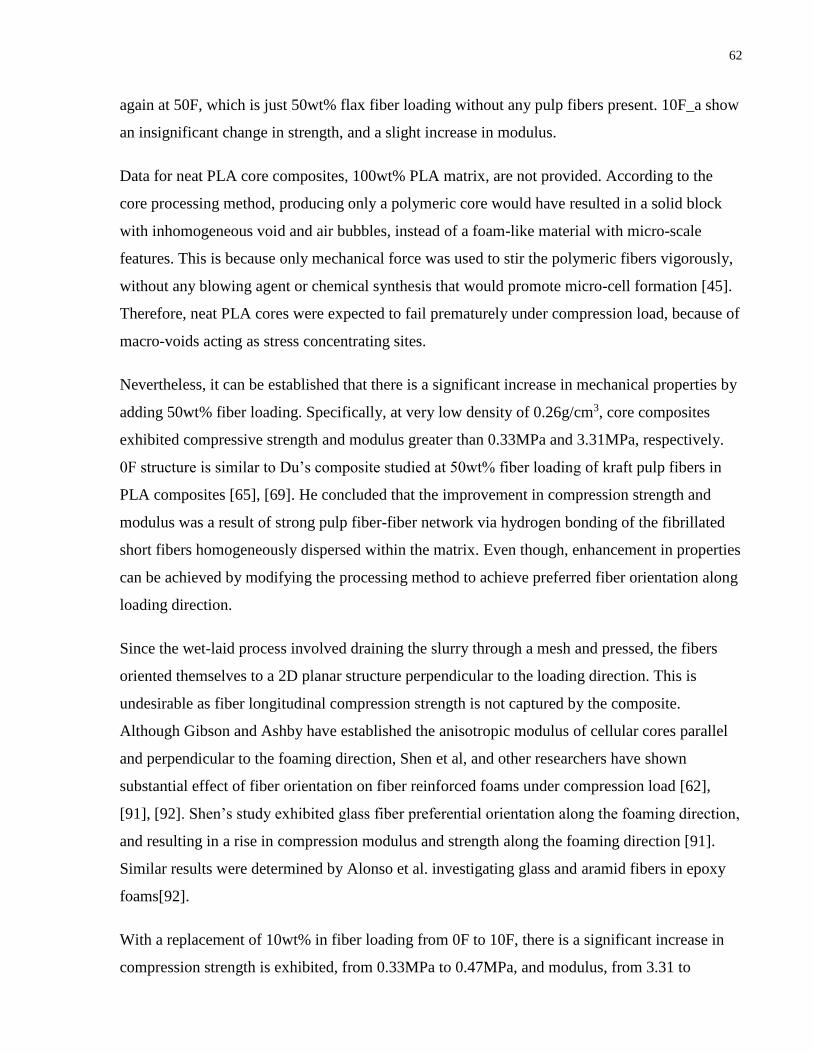
62
again at 50F, which is just 50wt% flax fiber loading without any pulp fibers present. 10F_a show
an insignificant change in strength, and a slight increase in modulus.
Data for neat PLA core composites, 100wt% PLA matrix, are not provided. According to the
core processing method, producing only a polymeric core would have resulted in a solid block
with inhomogeneous void and air bubbles, instead of a foam-like material with micro-scale
features. This is because only mechanical force was used to stir the polymeric fibers vigorously,
without any blowing agent or chemical synthesis that would promote micro-cell formation [45].
Therefore, neat PLA cores were expected to fail prematurely under compression load, because of
macro-voids acting as stress concentrating sites.
Nevertheless, it can be established that there is a significant increase in mechanical properties by
adding 50wt% fiber loading. Specifically, at very low density of 0.26g/cm3, core composites
exhibited compressive strength and modulus greater than 0.33MPa and 3.31MPa, respectively.
0F structure is similar to Du’s composite studied at 50wt% fiber loading of kraft pulp fibers in
PLA composites [65], [69]. He concluded that the improvement in compression strength and
modulus was a result of strong pulp fiber-fiber network via hydrogen bonding of the fibrillated
short fibers homogeneously dispersed within the matrix. Even though, enhancement in properties
can be achieved by modifying the processing method to achieve preferred fiber orientation along
loading direction.
Since the wet-laid process involved draining the slurry through a mesh and pressed, the fibers
oriented themselves to a 2D planar structure perpendicular to the loading direction. This is
undesirable as fiber longitudinal compression strength is not captured by the composite.
Although Gibson and Ashby have established the anisotropic modulus of cellular cores parallel
and perpendicular to the foaming direction, Shen et al, and other researchers have shown
substantial effect of fiber orientation on fiber reinforced foams under compression load [62],
[91], [92]. Shen’s study exhibited glass fiber preferential orientation along the foaming direction,
and resulting in a rise in compression modulus and strength along the foaming direction [91].
Similar results were determined by Alonso et al. investigating glass and aramid fibers in epoxy
foams[92].
With a replacement of 10wt% in fiber loading from 0F to 10F, there is a significant increase in
compression strength is exhibited, from 0.33MPa to 0.47MPa, and modulus, from 3.31 to

63
4.27MPa, presenting a positive hybrid effect. This increase can be attributed to addition of fibers
with a higher fiber aspect ratio and modulus, creating a more complex fiber-fiber network.
Additionally, the microstructure may have evolved from a 2D planar fiber orientation,
perpendicular to loading direction, to a more 3D random orientation, thus increasing fiber-
reinforcing effect. A mixture of long and short fibers provide sufficient mechanical interlocking
and do not settle as readily into 2D layer structure. Moreover, hydrogen bonding amongst the
biofibers could improve strength.
Conversely, flax fiber loading higher than 10wt% showed decreased compression strength and
modulus as the weak flax fiber-matrix interfacial bonding dominates the material behaviour
under compression load. Due to the weak interface, there is plasticizing effect, the fibers slip
through the matrix without carrying stress loads. Moreover, possible increased shearing during
processing, due to higher amounts of longer fibers being added, may have caused loss of strength
and modulus. 50F showed an improvement in properties, which may be attributed to the
inherently superior flax fiber properties and high fiber length. On the other hand, Alonso has
shown little effect of fiber length on compression strength [92]. And finally, alkalization of
10wt% flax fibers in 10F_a, as expected showed insignificant change from untreated 10F. The
reduced fiber strength and modulus of alkali flax fibers cancelled out the effect of improved
fiber-matrix interfacial adhesion. This effect was discussed in more detail in the previous
chapters.
To understand and improve upon the compression properties, a few core characteristics still need
to be addressed: density distribution, flax and pulp fiber dispersion, and fiber orientation. A
significant density distribution may attribute to weak regions within the core resulting in
premature buckling and collapse. Similarly, fiber agglomeration and incomplete wetting of fibers
may become stress concentrating sites and reduce properties. Also, fiber orientation plays a role
in determining overall composite processing as mentioned earlier. These weak regions may act
as failure initiating points for sandwich panels under flexural due to inability to carry high shear
stresses.

64
Figure 23: Compression strength of core composites and corresponding normalized values
at 0.26g/cm3
Figure 24: Compression modulus of core composites and corresponding normalized values
at 0.26g/cm3

65
3.2.2 Flexural properties and failure analysis of sandwich panels
Sandwich panels were produced as an attempt to understand the flexural properties of both face
and core components under load and to determine design parameters for improving biocomposite
performance for applicability as sandwich structures. Face components FFF and core
components 0F and 10F were made into two sets of sandwich panels, FFF0F and FFF10F, with
thickness ratio of t:c = 1:20. The total density of the sandwich structures were approximately
0.35g/cm3 at a thickness of 11mm, which shows high potential for constructing very lightweight
bio-based sandwich panels. Additionally, since the selected core components were based on their
compression properties, the sandwich panels inherit high compression strength and modulus.
Figure 25 show the failure mode for both sandwich panels to be core shearing. Compared to
other biofiber reinforced sandwich panels, similar failure mode is observed by Mak et al. at this
t:c ratio [67]. The faces were observed to undergo high deformation without fracture due to low
face modulus, about 3.6GPa, as discussed in section 2.2.2. Face-core interface was intact even at
very high strain, which showed good interfacial bonding without any use of adhesive.
Load-deflection curves of the sandwich panel flexural tests are given in Appendix B. Both panels
exhibited no catastrophic failure, as no large drop in the load-deflection curve is evident. The
behaviour is not fully understood however, it may be attributed to the flexible biofibers as
opposed to a sudden drop of stress such as for brittle glass fiber reinforced composites [91]. This
conjecture is also in agreement with Mak who observed more ductile failure of flax fiber
reinforced face components than that of glass fiber reinforced face components of studied
sandwich structures [67]. Consequently, due to core densification effect, the panel continues to
carry load with increased slope in the stress-strain curve, which allows an increase in stiffness
and prevents any catastrophic failure.
FFF0F samples show better flexural properties compared to FFF10F. This was not expected as
10F core showed superior compression properties. However, as exhibited in Figure 25,
substantially distinct core buckling and shearing is observed. Consequently, there is a
corresponding decrease in bending stiffness and failure load with use of 10F core, as shown
below. This behavior cannot be understood with only flexural test of sandwich panel, and
therefore, further tests need to be conducted to identify the reasons for decreasing properties.
Specifically, shear testing of the core composites are necessary to understand the failure
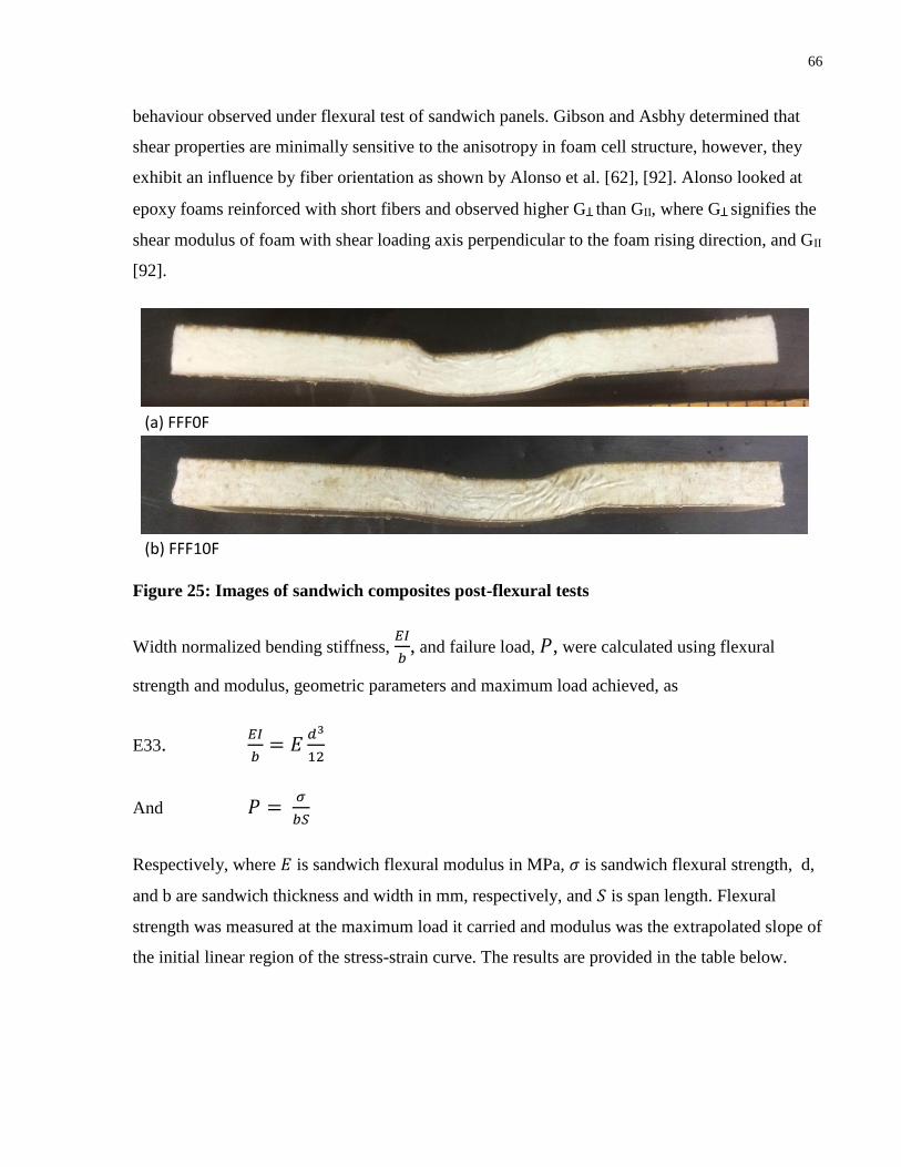
66
behaviour observed under flexural test of sandwich panels. Gibson and Asbhy determined that
shear properties are minimally sensitive to the anisotropy in foam cell structure, however, they
exhibit an influence by fiber orientation as shown by Alonso et al. [62], [92]. Alonso looked at
epoxy foams reinforced with short fibers and observed higher GꞱ than GII, where GꞱ signifies the
shear modulus of foam with shear loading axis perpendicular to the foam rising direction, and GII
[92].
(a) FFF0F
(b) FFF10F
Figure 25: Images of sandwich composites post-flexural tests
Width normalized bending stiffness, 𝐸𝐼
𝑏, and failure load, 𝑃, were calculated using flexural
strength and modulus, geometric parameters and maximum load achieved, as
E33. 𝐸𝐼
𝑏= 𝐸
𝑑3
12
And 𝑃 = 𝜎
𝑏𝑆
Respectively, where 𝐸 is sandwich flexural modulus in MPa, 𝜎 is sandwich flexural strength, d,
and b are sandwich thickness and width in mm, respectively, and 𝑆 is span length. Flexural
strength was measured at the maximum load it carried and modulus was the extrapolated slope of
the initial linear region of the stress-strain curve. The results are provided in the table below.

67
Table 11: Flexural test results shown for FFF0F and FFF10F sandwich panels
3.2.3 SEM morphology of core composites and sandwich panels
SEM images were captured of the face-core interface and core component of the sandwich
panels, provided in Figure 26. The face-core interface shows good adhesion as there are is no
distinct interfacial border between the two components. 0F core shows well distributed pulp
fibers within the matrix and good fiber-matrix adhesion. There is an indication of fiber
orientation along the plane perpendicular to the thickness of the core. This justifies the
speculation made in the previous section, caused by wet-laid processing method. Conversely,
10F core does not show an apparent fiber orientation. Additionally, flax fibers show weaker
fiber-matrix adhesion and are easily distinguishable compared with pulp fibers.

68
(a) Interface between FFF face and 10F core
(b) 0F core cross-section (c) 10F core cross-section
Figure 26: SEM images of sandwich panel cross-section: (a) face-core interface, (b) 10F core, (c) 0F core
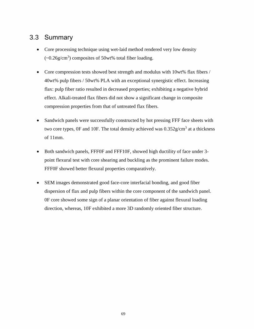
69
3.3 Summary
Core processing technique using wet-laid method rendered very low density
(~0.26g/cm3) composites of 50wt% total fiber loading.
Core compression tests showed best strength and modulus with 10wt% flax fibers /
40wt% pulp fibers / 50wt% PLA with an exceptional synergistic effect. Increasing
flax: pulp fiber ratio resulted in decreased properties; exhibiting a negative hybrid
effect. Alkali-treated flax fibers did not show a significant change in composite
compression properties from that of untreated flax fibers.
Sandwich panels were successfully constructed by hot pressing FFF face sheets with
two core types, 0F and 10F. The total density achieved was 0.352g/cm3 at a thickness
of 11mm.
Both sandwich panels, FFF0F and FFF10F, showed high ductility of face under 3-
point flexural test with core shearing and buckling as the prominent failure modes.
FFF0F showed better flexural properties comparatively.
SEM images demonstrated good face-core interfacial bonding, and good fiber
dispersion of flax and pulp fibers within the core component of the sandwich panel.
0F core showed some sign of a planar orientation of fiber against flexural loading
direction, whereas, 10F exhibited a more 3D randomly oriented fiber structure.

70
Conclusion
Flax fibers and pulp fibers were studied to determine a hybridization effect in a
biofiber hybrid PLA composite system. Tensile modulus was studied to show a slight
positive hybridization effect of 10wt% flax / 20wt% pulp / PLA composites, w.r.t
their corresponding non-hybrid fiber composites systems, via Hybrid rule of mixtures
equation (HROM). Hybrid Halpin-Tsai curves were modelled as well, and showed an
overestimation of tensile modulus for the hybrid composites. Fiber aspect ratios were
not considered in these calculations; rather, the fiber correction factor was empirically
determined to best fit experimental data. Sum of squared errors showed HROM to be
the best fitting curve.
Alkalization treatment of flax fibers at 5% NaOH solution concentration increased the
amount of hydroxyl groups at the fiber surface, by removal of hemicellulose, lignin,
oils, and pectin, and improved thermal degradation temperatures. As well, in PLA
composite systems, alkali fibers improved fiber-matrix interface, which was however,
not reflected in its composite tensile properties. Justification was discussed to be due
to a decrease in fiber tensile properties post-alkalization.
Core composites were made with wet-laid processing of varying flax: pulp fiber ratio
in 50twt% fiber loading PLA composites. Best core compression properties were
shown by 10wt% flax/ 40wt% pulp/ 50wt% PLA. Higher flax: pulp ratio showed a
decrease in compression strength, which indicated an overall negative hybrid effect.
Sandwich panels were successfully constructed by hot pressing best combinations of
face sheet composites and core composites achieving a very low total density of
0.35g/cm3 and inheriting high compression properties as that of the tested core
components.
Specifically, two sandwich panels were made using 30wt% flax fiber PLA composites
for face sheets, hot pressed with two types of low density core: 50wt% pulp fiber PLA
composite, or 10wt% flax/ 40wt% pulp fiber PLA composite. Both showed prominent
core buckling and shearing as the failure modes due to low face bending stiffness and
low core shear strength, respectively.

71
Future Work and Recommendations
Flax fibers after alkalization treatment need further analysis to determine their
behavior as reinforcing agents in PLA biocomposites. Specifically, its microstructure
change, tensile strength and modulus needs to be tested for a clearer picture. Contact
angle measurements of untreated and treated fiber surfaces can portray a clearer
picture of alkalization influence on the surface energy and hydrophobicity change.
This information will help improve alkali processing of flax fibers for enhanced
properties.
An optimization study on the processing parameters of flax/pulp/PLA hybrid laminate
sheet composites will help produce higher mechanical performance composites.
Specifically, pressing time, temperature and pressure influence void content, fiber
wetting, and degradation, which effect overall composite tensile modulus and
strength.
Differential scanning calorimetry (DSC) and Thermal gravimetric analysis (TGA) of
raw materials pre- and post- alkali treatment, and of fiber reinforced PLA composites
need to be carried out to understand the performance of materials with respect to
temperature and determine crystallization and degradation behavior of material and
their corresponding composites. These analysis techniques also help in providing a
clearer picture of the influence of composite performance on processing parameters.
Fiber dispersion of core composites needs to be studied throughout the samples to
confirm proper disintegration of flax and pulp fibers. By dissolving PLA in a suitable
solvent, fiber weight fraction can be acquired; this experiment can also allow
possibility of measuring post-processing fiber length distribution, which will provide
more insight on fiber reinforcing effect under compression and shear load.
Density distribution of core composites along the cross-section can help map and
identify the weak regions where compression buckling initiates. Processing methods
will need to be adjusted to reduce density variation along the cross-section of the core.
Processing methods may need to be revisited to allow a slower cooling rate for
decreased expansion. Also, lower pressure may result in decreased residual stresses.

72
Shear test of core composites are necessary to understand the behavior of the core
component in sandwich panel flexural tests. Increase in shear properties of core
composites is of high importance to improve upon sandwich panel performance.
Lightweight biofiber reinforced sandwich structured composites need a lot more
research to achieve high mechanical performance to satisfy specifications of structural
applications. Specifically, core shear modulus and face elastic modulus are of high
importance based on the sandwich theory. Higher shear modulus and compression
strength will be achieved by preferential orientation of fibers along the elastic bending
axis. Additionally, face composites of higher fiber loading and thickness will improve
tensile modulus and flexural rigidity and, hence, bending stiffness carried by the
sandwich panel.
Dynamic mechanical analysis (DMA) of sandwich panels and their constitiuent face
and core components can be conducted to exhibit the temperature and frequency
dependence of composite mechanical properties. Accurate thermo-mechanical results
under tensile, compression, flexural and shear loading types can be acquired.
Other properties of sandwich panels are of interest to explore their applicability,
namely, impact properties, thermal stability, thermal conductivity, and moisture
sensitivity. More samples of sandwich panels need to be tested of varying geometric
ratio of c/t to determine the influence of geometric design to failure mode.
73
References
[1] T. J. O’Neill, Life Cycle Assessment and Environmental Impact of Polymeric Products.
iSmithers Rapra Publishing, 2003.
[2] S. M. Batouli and Y. Zhu, “Comparative Life-Cycle Assessment Study of Kenaf Fiber-
Based and Glass Fiber-Based Structural Insulation Panels,” Iccrem 2013, pp. 377–388,
2013.
[3] A. Le Duigou, J. M. Deux, P. Davies, and C. Baley, “PLLA/flax mat/balsa bio-sandwich-
environmental impact and simplified life cycle analysis,” Appl. Compos. Mater., vol. 19,
no. 3–4, pp. 363–378, 2012.
[4] L. Yan, N. Chouw, and K. Jayaraman, “Flax fibre and its composites - A review,”
Compos. Part B Eng., vol. 56, pp. 296–317, 2014.
[5] Flax coucil of canada, “Flax Industry - new vision,” 2016.
[6] D. E. Akin, “Linen most useful: Perspectives on structure, chemistry, and enzymes for
retting flax,” ISRN Biotechnol., vol. 2013, p. 23, 2013.
[7] “Cigarette Paper Applications,” Schweitzer Mouduit International. [Online]. Available:
http://www.swmintl.com/products/cigarette-paper-applications. [Accessed: 01-Jul-2016].
[8] “Projects,” Composites Innovation Center. [Online]. Available:
http://www.compositesinnovation.ca/projects/?doing_wp_cron=1473055942.5871019363
403320312500. [Accessed: 01-Apr-2016].
[9] “Chapter 12: Flax Straw and Fibre, Past and Present Uses,” Flax Council of Canada.
[Online]. Available: http://flaxcouncil.ca/growing-flax/chapters/flax-straw-and-fibre/.
[Accessed: 20-Aug-2016].
[10] I. Van de Weyenberg, J. Ivens, A. De Coster, B. Kino, E. Baetens, and I. Verpoest,
“Influence of processing and chemical treatment of flax fibres on their composites,”
Compos. Sci. Technol., vol. 63, no. 9, pp. 1241–1246, 2003.

74
[11] D. B. Dittenber and H. V. S. Gangarao, “Critical review of recent publications on use of
natural composites in infrastructure,” Compos. Part A Appl. Sci. Manuf., vol. 43, no. 8, pp.
1419–1429, 2012.
[12] H. S. S. Sharma, T. W. Fraser, D. McCall, N. Shields, and G. Lyons, “Fine Structure of
Chemically Modified Flax Fibre,” J. Text. Inst., vol. 86, no. 4, pp. 539–548, 1995.
[13] H. Ku, H. Wang, N. Pattarachaiyakoop, and M. Trada, “A review on the tensile properties
of natural fiber reinforced polymer composites,” Compos. Part B Eng., vol. 42, no. 4, pp.
856–873, 2011.
[14] D. N. SAHEB and J. P. JOG, “Natural Fiber Polymer Composites : A Review,” Adv.
Polym. Technol., vol. 18, no. 4, pp. 351–363, 1999.
[15] O. Faruk, A. K. Bledzki, H.-P. Fink, and M. Sain, “Progress Report on Natural Fiber
Reinforced Composites,” Macromol. Mater. Eng., vol. 299, no. 1, pp. 9–26, 2014.
[16] W. D. Callister and J. D. G. Rethwisch, Fundamentals of Materials Science and
Engineering, Third. United States: John Wiley & Sons, 2008.
[17] D. U. Shah, “Developing plant fibre composites for structural applications by optimising
composite parameters: A critical review,” J. Mater. Sci., vol. 48, no. 18, pp. 6083–6107,
2013.
[18] S. Huo, a. Thapa, and C. a. Ulven, “Effect of surface treatments on interfacial properties
of flax fiber-reinforced composites,” Adv. Compos. Mater., vol. 22, no. 2, pp. 109–121,
2013.
[19] A. K. Bledzki, A. A. Mamun, M. Lucka-Gabor, and V. S. Gutowski, “The effects of
acetylation on properties of flax fibre and its polypropylene composites,” Express Polym.
Lett., vol. 2, no. 6, pp. 413–422, 2008.
[20] S. Alix, E. Philippe, A. Bessadok, L. Lebrun, C. Morvan, and S. Marais, “Effect of
chemical treatments on water sorption and mechanical properties of flax fibres,”
Bioresour. Technol., vol. 100, no. 20, pp. 4742–4749, 2009.

75
[21] N. Le Moigne, M. Longerey, J. M. Taulemesse, J. C. Benezet, and A. Bergeret, “Study of
the interface in natural fibres reinforced poly(lactic acid) biocomposites modified by
optimized organosilane treatments,” Ind. Crops Prod., vol. 52, pp. 481–494, 2014.
[22] S. Shokoohi, a. Arefazar, and R. Khosrokhavar, “Silane Coupling Agents in Polymer-
based Reinforced Composites: A Review,” J. Reinf. Plast. Compos., vol. 27, no. 5, pp.
473–485, 2008.
[23] Y. Song, J. Liu, S. Chen, Y. Zheng, S. Ruan, and Y. Bin, “Mechanical Properties of Poly
(Lactic Acid)/Hemp Fiber Composites Prepared with a Novel Method,” J. Polym.
Environ., vol. 21, no. 4, pp. 1117–1127, 2013.
[24] J. Gassan, I. Mildner, and a. K. Bledzki, “Influence of fiber structure modification on the
mechanical properties of flax fiber-epoxy composites,” Mech. Compos. Mater., vol. 35,
no. 5, pp. 435–440, 1999.
[25] G. O. Mehmet Kodal, Zeynep Demir Topuk, “Dual effect of chemical modification and
polymer precoating of flax fibers on the properties of short flax fiber/poly(lactic acid)
composites,” J. Appl. Polym. Sci., p. 42564, 2015.
[26] Z. Liu, S. Z. Erhan, D. E. Akin, F. E. Barton, C. Onwulata, and T. A. McKeon, “Modified
flax fibers reinforced soy-based composites: mechanical properties and water absorption
behavior,” Compos. Interfaces, vol. 15, no. 2–3, pp. 207–220, 2008.
[27] M. E. E. G. Bogoeva-Gaceva, M. Avella, M. Malinconico, A. Buzarovska, A. Grozdanov,
G. Gentile, “Natural fiber eco-composites,” Polym. Compos., pp. 98–107, 2007.
[28] I. Van de Weyenberg, T. Chi Truong, B. Vangrimde, and I. Verpoest, “Improving the
properties of UD flax fibre reinforced composites by applying an alkaline fibre treatment,”
Compos. Part A Appl. Sci. Manuf., vol. 37, no. 9, pp. 1368–1376, 2006.
[29] A. Arbelaiz, G. Cantero, B. Fernandez, I. Mondragon, P. Ganan, and J. M. Kenny, “Flax
fiber surface modifications: Effects on fiber physico mechanical and flax/polypropylene
interface properties,” Polym. Compos., vol. 26, no. 3, pp. 324–332, 2005.
[30] D. Fengel and G. Wegener, Wood: chemistry, ultrastructure, reactions. Berlin: de Gruyte,
76
1983.
[31] J. T. Kim and A. N. Netravali, “Mercerization of sisal fibers: Effect of tension on
mechanical properties of sisal fiber and fiber-reinforced composites,” Compos. Part A
Appl. Sci. Manuf., vol. 41, no. 9, pp. 1245–1252, 2010.
[32] N. Suizu, T. Uno, K. Goda, and J. Ohgi, “Tensile and impact properties of fully green
composites reinforced with mercerized ramie fibers,” J. Mater. Sci., vol. 44, no. 10, pp.
2477–2482, 2009.
[33] J. Gassan and A. K. Bledzki, “Possibilities for improving the mechanical properties of
jute/epoxy composites by alkali treatment of fibres,” Compos. Sci. Technol., vol. 59, no. 9,
pp. 1303–1309, 1999.
[34] M. Aydin, H. Tozlu, S. Kemaloglu, A. Aytac, and G. Ozkoc, “Effects of Alkali Treatment
on the Properties of Short Flax Fiber-Poly(Lactic Acid) Eco-Composites,” J. Polym.
Environ., vol. 19, no. 1, pp. 11–17, 2011.
[35] E. Privas and P. Navard, “Preparation, processing and properties of lignosulfonate-flax
composite boards,” Carbohydr. Polym., vol. 93, no. 1, pp. 300–306, 2013.
[36] H. N. Dhakal, Z. Y. Zhang, and N. Bennett, “Influence of fibre treatment and glass fibre
hybridisation on thermal degradation and surface energy characteristics of
hemp/unsaturated polyester composites,” Compos. Part B Eng., vol. 43, no. 7, pp. 2757–
2761, 2012.
[37] K. Oksman, A. P. Mathew, R. Langstrom, B. Nystrom, and K. Joseph, “The influence of
fibre microstructure on fibre breakage and mechanical properties of natural fibre
reinforced polypropylene,” Compos. Sci. Technol., vol. 69, no. 11–12, pp. 1847–1853,
2009.
[38] K. Oksman, M. Skrifvars, and J. F. Selin, “Natural fibres as reinforcement in polylactic
acid (PLA) composites,” Compos. Sci. Technol., vol. 63, no. 9, pp. 1317–1324, 2003.
[39] P. Suhara and M. Sain, “Injection-Molded Short Hemp Fiber/Glass Fiber- Reinforced
Polypropylene Hybrid Composites— Mechanical, Water Absorption and Thermal
77
Properties,” Polym. Polym. Compos., vol. 103, pp. 2432–2441, 2007.
[40] Y. Swolfs, L. Gorbatikh, and I. Verpoest, “Fibre hybridisation in polymer composites: A
review,” Compos. Part A Appl. Sci. Manuf., vol. 67, pp. 181–200, 2014.
[41] J. C. Halpin and J. L. Kardos, “Halpin-Tsai Equations - Review,” Polym. Eng. Sci., vol.
16, no. 5, pp. 344–352, 1976.
[42] A. G. Facca, M. T. Kortschot, and N. Yan, “PREDICTING THE TENSILE MODULUS
AND STRENGTH OF SINGLE AND HYBRID NATURAL FIBRE REINFORCED
THERMOPLASTIC COMPOSITES,” University of Toronto, 2007.
[43] A. G. Facca, M. T. Kortschot, and N. Yan, “Predicting the elastic modulus of natural fibre
reinforced thermoplastics,” Compos. Part A Appl. Sci. Manuf., vol. 37, no. 10, pp. 1660–
1671, 2006.
[44] J. Biagiotti, S. Fiori, L. Torre, M. Lopez-Manchado, and J. Kenny, “Mechanical properties
of polypropylene matrix composites reinforced with natural fibers: a statistical approach,”
Polym. Compos., vol. 25, no. 1, pp. 26–31, 2004.
[45] L. T. Lim, R. Auras, and M. Rubino, “Processing technologies for poly(lactic acid),”
Prog. Polym. Sci., vol. 33, no. 8, pp. 820–852, 2008.
[46] A. P. Mathew, K. Oksman, and M. Sain, “Mechanical properties of biodegradable
composites from poly lactic acid (PLA) and microcrystalline cellulose (MCC),” J. Appl.
Polym. Sci., vol. 97, no. 5, pp. 2014–2025, 2005.
[47] M. Jonoobi, J. Harun, A. P. Mathew, and K. Oksman, “Mechanical properties of cellulose
nanofiber (CNF) reinforced polylactic acid (PLA) prepared by twin screw extrusion,”
Compos. Sci. Technol., vol. 70, no. 12, pp. 1742–1747, 2010.
[48] N. Herrera, A. M. Salaberria, A. P. Mathew, and K. Oksman, “Plasticized polylactic acid
nanocomposite films with cellulose and chitin nanocrystals prepared using extrusion and
compression molding with two cooling rates: Effects on mechanical, thermal and optical
properties,” Compos. Part A Appl. Sci. Manuf., 2015.
78
[49] A. Iwatake, M. Nogi, and H. Yano, “Cellulose nanofiber-reinforced polylactic acid,”
Compos. Sci. Technol., vol. 68, no. 9, pp. 2103–2106, 2008.
[50] L. Suryanegara, A. N. Nakagaito, and H. Yano, “The effect of crystallization of PLA on
the thermal and mechanical properties of microfibrillated cellulose-reinforced PLA
composites,” Compos. Sci. Technol., vol. 69, no. 7–8, pp. 1187–1192, 2009.
[51] M. S. Sreekala, J. George, M. G. Kumaran, and S. Thomas, “The mechanical performance
of hybrid phenol-formaldehyde-based composites reinforced with glass and oil palm
fibres,” Compos. Sci. Technol., vol. 62, no. 3, pp. 339–353, 2002.
[52] M. Jawaid and H. P. S. Abdul Khalil, “Cellulosic/synthetic fibre reinforced polymer
hybrid composites: A review,” Carbohydr. Polym., vol. 86, no. 1, pp. 1–18, 2011.
[53] S. Nunna, P. R. Chandra, S. Shrivastava, and a. Jalan, “A review on mechanical behavior
of natural fiber based hybrid composites,” J. Reinf. Plast. Compos., vol. 31, no. 11, pp.
759–769, 2012.
[54] S. C. Amico, C. C. Angrizani, and M. L. Drummond, “Influence of the Stacking Sequence
on the Mechanical Properties of Glass/Sisal Hybrid Composites,” J. Reinf. Plast.
Compos., vol. 29, no. 2, pp. 179–189, 2010.
[55] C. C. Angrizani, M. O. Cioffi, a. J. Zattera, and S. C. Amico, “Analysis of curaua/glass
hybrid interlayer laminates,” J. Reinf. Plast. Compos., vol. 33, no. 5, pp. 472–478, 2014.
[56] R. Petrucci, C. Santulli, D. Puglia, E. Nisini, F. Sarasini, J. Tirill??, L. Torre, G. Minak,
and J. M. Kenny, “Impact and post-impact damage characterisation of hybrid composite
laminates based on basalt fibres in combination with flax, hemp and glass fibres
manufactured by vacuum infusion,” Compos. Part B Eng., vol. 69, pp. 507–515, 2015.
[57] A. Haneefa, P. Bindu, I. Aravind, and S. Thomas, “Studies on tensile and flexural
properties of short banana/glass hybrid fiber reinforced polystyrene composites,” J.
Compos. Mater., vol. 42, no. 15, pp. 1471–1489, 2008.
[58] H. Abdul Khalil, S. Hanida, and C. Kang, “Agro- hybrid composite: the effects on
mechanical and physical properties of oil palm fiber (EFB)/glass hybrid reinforced
79
polyester composites,” J. Reinf. Plast. Compos., vol. 26, no. 2, pp. 203–218, 2007.
[59] M. Jawaid, H. P. S. Abdul Khalil, and A. Abu Bakar, “Mechanical performance of oil
palm empty fruit bunches/jute fibres reinforced epoxy hybrid composites,” Mater. Sci.
Eng. A, vol. 527, no. 29–30, pp. 7944–7949, 2010.
[60] M. Idicula, K. Joseph, and S. Thomas, “Mechanical Performance of Short Banana/Sisal
Hybrid Fiber Reinforced Polyester Composites,” J. Reinf. Plast. Compos., vol. 29, no. 1,
pp. 12–29, 2009.
[61] N. Venkateshwaran, A. ElayaPerumal, A. Alavudeen, and M. Thiruchitrambalam,
“Mechanical and water absorption behaviour of banana/sisal reinforced hybrid
composites,” Mater. Des., vol. 32, no. 7, pp. 4017–4021, 2011.
[62] L. J. Gibson and M. F. Ashby, Cellular Solids: Structure and Properties, First. Oxford,
England: Pergamon Press, 1987.
[63] J. M. Davies, Lightweight Sandwich Construction. Wiley, 2008.
[64] B. K. Wright, “Validation of Point and Pressure Loading Models for Simply Supported
Composite Sandwich Beams,” University of Toronto, 2012.
[65] Y. Du, N. Yan, and M. T. Kortschot, “Novel lightweight sandwich-structured bio-fiber-
reinforced poly(lactic acid) composites,” J. Mater. Sci., vol. 49, no. 5, pp. 2018–2026,
2014.
[66] Y. Karaduman and L. Onal, “Flexural behavior of commingled jute / polypropylene
nonwoven fabric reinforced sandwich composites,” Compos. Part B, vol. 93, pp. 12–25,
2016.
[67] K. Mak, A. Fam, M. Asce, and C. Macdougall, “Flexural Behavior of Sandwich Panels
with Bio-FRP Skins Made of Flax Fibers and Epoxidized Pine-Oil Resin,” J. Compos.
Constr., vol. 19, no. 2003, pp. 1–13, 2015.
[68] M. M. Kabir, H. Wang, K. T. Lau, F. Cardona, and T. Aravinthan, “Mechanical properties
of chemically-treated hemp fibre reinforced sandwich composites,” Compos. Part B Eng.,

80
vol. 43, no. 2, pp. 159–169, 2012.
[69] Y. Du, N. Yan, and M. T. Kortschot, “A simplified fabrication process for biofiber-
reinforced polymer composites for automotive interior trim applications,” J. Mater. Sci.,
vol. 49, no. 6, pp. 2630–2639, 2014.
[70] J. Holbery and D. Houston, “Natural-fibre-reinforced polymer composites in automotive
applications,” Jom, vol. 58, no. 11, pp. 80–86, 2006.
[71] J. A. Foulk, D. E. Akin, and R. B. Dodd, “Processability of flax plant stalks into
functional bast fibers,” Compos. Interfaces, vol. 15, no. 2–3, pp. 147–168, 2008.
[72] P. Grad, “Renewed Optimism in the Pulp-and-Paper Industry,” TradeFair Group
Publications Ltd., Jul-2015.
[73] I. Sir?? and D. Plackett, “Microfibrillated cellulose and new nanocomposite materials: A
review,” Cellulose, vol. 17, no. 3, pp. 459–494, 2010.
[74] Y. Du, T. Wu, N. Yan, M. T. Kortschot, and R. Farnood, “Fabrication and
characterization of fully biodegradable natural fiber-reinforced poly(lactic acid)
composites,” Compos. Part B Eng., vol. 56, pp. 717–723, 2014.
[75] A. Ashori and A. Nourbakhsh, “Characteristics of wood-fiber plastic composites made of
recycled materials,” Waste Manag., vol. 29, no. 4, pp. 1291–1295, 2009.
[76] A. Awal, S. Ghosh, and M. Sain, “Thermal properties and spectral characterization of
wood pulp reinforced bio-composite fibers,” J. Therm. Anal. Calorim., vol. 99, no. 2, pp.
695–701, 2009.
[77] R. G. Raj, B. V. Kokta, D. Maldas, and C. Daneault, “Use of wood fibers in
thermoplastics. VII. The effect of coupling agents in polyethylene–wood fiber
composites,” J. Appl. Polym. Sci., vol. 37, pp. 1089–1103, 1989.
[78] D. K. R. R. T. Woodhams, G. Thomas, “Wood Fibers as Reinforcing Fillers for
Polyolefins,” Polym. Eng. Sci., vol. 24, no. 15, pp. 1166–1171, 1984.
81
[79] H. P. S. Aabdul Khalil, C. W. Kang, a. Khairul, R. Ridzuan, and T. O. Adawi, “The
Effect of Different Laminations on Mechanical and Physical Properties of Hybrid
Composites,” J. Reinf. Plast. Compos., vol. 28, no. 9, pp. 1123–1137, 2008.
[80] M. S. Huda, L. T. Drzal, A. K. Mohanty, and M. Misra, “Effect of fiber surface-treatments
on the properties of laminated biocomposites from poly(lactic acid) (PLA) and kenaf
fibers,” Compos. Sci. Technol., vol. 68, no. 2, pp. 424–432, 2008.
[81] E. J. Barbero, “Introduction to Composite Materials Design,” Hum. Fertil. Cambridge
Engl., vol. 73, p. 520, 2011.
[82] M. Le Troedec, D. Sedan, C. Peyratout, J. P. Bonnet, A. Smith, R. Guinebretiere, V.
Gloaguen, and P. Krausz, “Influence of various chemical treatments on the composition
and structure of hemp fibres,” Compos. Part A Appl. Sci. Manuf., vol. 39, no. 3, pp. 514–
522, 2008.
[83] M. Sawpan, K. Pickering, and A. Fernyhough, “Effect of fibre treatments on interfacial
shear strength of hemp fibre reinforced polylactide and unsaturated polyester composites,”
Compos. Part A Appl. Sci. Manuf., vol. 42, no. 9, pp. 1189–1196, 2011.
[84] M. A. Sawpan, K. L. Pickering, and A. Fernyhough, “Effect of various chemical
treatments on the fibre structure and tensile properties of industrial hemp fibres,” Compos.
Part A Appl. Sci. Manuf., vol. 42, no. 8, pp. 888–895, 2011.
[85] I. Taha, L. Steuernagel, and G. Ziegmann, “Optimization of the alkali treatment process of
date palm fibres for polymeric composites,” Compos. Interfaces, vol. 14, no. 7–9, pp.
669–684, 2007.
[86] M. S. Sreekala, M. G. Kumaran, and S. Thomas, “Oil Palm Fibers : Morphology ,
Chemical Composition , Surface Modification , and Mechanical Properties,” J. Appl.
Polym. Sci., vol. 66, pp. 821–835, 1997.
[87] R. F. Gibson, “A review of recent research on mechanics of multifunctional composite
materials and structures,” Compos. Struct., vol. 92, no. 12, pp. 2793–2810, 2010.
[88] A. K. Bledzki, H. P. Fink, and K. Specht, “Unidirectional hemp and flax EP- and PP-

82
composites: Influence of defined fiber treatments,” J. Appl. Polym. Sci., vol. 93, no. 5, pp.
2150–2156, 2004.
[89] P. K. Kushwaha and R. Kumar, “The Studies on Performance of Epoxy and Polyester-
based Composites Reinforced with Bamboo and Glass Fibers,” J. Reinf. Plast. Compos.,
vol. 29, no. 13, pp. 1952–1962, 2010.
[90] N. Graupner, G. Ziegmann, F. Wilde, F. Beckmann, and J. Müssig, “Procedural influences
on compression and injection moulded cellulose fibre-reinforced polylactide (PLA)
composites: Influence of fibre loading, fibre length, fibre orientation and voids,” Compos.
Part A Appl. Sci. Manuf., vol. 81, pp. 158–171, 2016.
[91] H. Shen and S. Nutt, “Mechanical characterization of short fiber reinforced phenolic
foam,” Compos. Part A Appl. Sci. Manuf., vol. 34, no. 9, pp. 899–906, 2003.
[92] M. V. Alonso, M. L. Auad, and S. Nutt, “Short-fiber-reinforced epoxy foams,” Compos.
Part A Appl. Sci. Manuf., vol. 37, no. 11, pp. 1952–1960, 2006.

83
Appendix A: Flax fiber bundle analysis results
We commissioned Composite Innovation Centre (CIC) to carry out a detailed analysis of
untreated flax fibers. The results are discussed in the thesis section 2.2.1. Table 12 below
provides detail on the analysis type, instrument name and conditions for tests carried out. Figure
27 and Table 13 show XRD data that was used to calculate cellulose I crystallinity index for
untreated flax fibers. And, Table 14 presents fiber tensile test data for untreated flax fiber
bundles.
Table 12: Analyses done on untreated flax fiber and their descriptions
ANALYSIS INSTRUMENT USED CONDITIONS
Fiber apparent
density
Gas Pycnometer Under Nitrogen environment
Chemical
composition
Agilent Cary FTS 670 Fourier
Transform Infrared (FTIR)
Spectrometer
ATR scan
Spectral resolution 2cm-1
wavelength range: 400 – 4000cm-1 Crystallinity index Agilent SuperNova A Cu X-Ray
Diffractometer
φ rotation angle: -30o – 90o
Test duration: 180s
Calculation using Segal’s method
Fiber diameter
Tensile strength
Dia-Stron Fibre Dimensional
System with LEX820 High-
resolution Extensometer

84
Figure 27: XRD spectra of untreated flax fibers showing intensity for I002 and Iam
Table 13: XRD diffraction angle position for calculating cellulose crystallinity index of
untreated flax fibers

85
Table 14: Fiber tensile test for untreated flax fiber bundles showing mean diameter and
corresponding tensile strength values. Highlighted rows show the closest representation to
single fiber tensile strength data

86
Appendix B: Load-deflection curves of flax/pulp/PLA composites
Load deflection curves are of mechanical test data used to calculate properties and understand
mechanical behaviour under different loading conditions. Figure 28, Figure 29, Figure 30 below
present load-deflection curves of face component tensile test, core component compression test,
and sandwich panel 3-point bending test.
Figure 28: Load-deflection curve for face sheet composites tensile test

87
Figure 29: Load-deflection curve for core compression test
Figure 30: Load-deflection curve for sandwich panel 3-point flexural test