FAA Order 6350.22 - RML Replacement & Expansion Project ... · special-purpose RML system into a...
64
6350.22 ORDER RML REPLACEMENT AND EXPANSION PROJECT RADIO COMMUNICATIONS LINK 'SYSTEM IMPLEMENTATION PLAN. November 1986 DEPARTMENT OF TRANSP.ORTATION FEDERAL AVIATION ADMINISTRATION Distribution: A-W(PMtES/LG/PT)-2; A-X(AF)-3; A-Y(AY/DE)-3; Initiated By: APM-510 A-FAF-2/3/7(LTD) ··
Transcript of FAA Order 6350.22 - RML Replacement & Expansion Project ... · special-purpose RML system into a...

635022ORDER
RML REPLACEMENT AND EXPANSION PROJECT RADIO COMMUNICATIONS LINK
SYSTEM IMPLEMENTATION PLAN
November 21~ 1986
DEPARTMENT OF TRANSPORTATION FEDERAL AVIATION ADMINISTRATION
Distribution A-W(PMtESLGPT)-2 A-X(AF)-3 A-Y(AYDE)-3 Initiated By APM-510 A-FAF-237(LTD) middotmiddot
112186 635022
FOREWORD
This order provides management direction and technical guidelines for the implementation of a portion of the NAS (National Airspace System) Plan RML (Radar Microwave Link) Replacement and Expansion Project Effort on this project will be directed toward developing a nationwide microwave transmission system known as the radio communications link (RCL) system This system will form an interconnecting BACKBONE which will serve the communication needs of the NAS elements as they are developed This plan covers the implementation of the microwave radios repeaters and terminals including antennas waveguide multiplexing equipment and the Automatic Network Management System (AMMS)
This plan is prepared under the direction of the FAA project manager (APM-510) who will review it frequently and coordinate revisions as necessary
This plan has been kept broad in scope in order to be a practical working instrument It is designed to encourage the interactive sharing of information between the FAA headquarters FAA regions and all other project participants This LIVING MANAGEMENT TOOL is intended to be flexible It permits noncontractural judgements and determinations to be made by all participants as conditions and needs arise
~~ _lhomas J o~~rien~- _~~ting Director Program EngineeringL)v and Maintenance Service
Page (and i i)
112186 635022
TABLE OF CONTENTS
Page No
CHAPTER 1 GENERAL 1
1 Purpose and scope 1 2 Distribution 1 3 Maintenance and Modification of the Plan 1 4-19 Reserved 1
CHAPTER 2 PROJECT OVERVIEW 3
20 Project Scope 3 21 Present System 3 22 Future System 4 23-29 Reserved 4
CHAPTER 3 PROJECT MANAGEMENT 7
30 Implementation 7 31 Program Management Structure 7 32 Project Communications 8 33 Project Coordination 8 34 Implementation Procedures 8 35 Project Responsibilities 16 36-39 Reserved 20
CHAPTER 4 PROJECT CONTROL 23
40 Implementation Management 23 41 Fiscal Consideration 23 42 Implementation Schedule 24 43 Control Techniques 24 44 Configuration Management 25 45 Project Quality Assurance 25 46-49 Reserved 25
CHAPTER 5 PROJECT ENGINEERING 27
so General 27 51 MITRE Corp 27 52 SEIC Engineering Support 27 53 Tower Engineering 28 54 Related Projects 28 55-59 Reserved 28
Page iii
112186
635022
CHAPTER 6
60 61 62-69
CHAPTER 7
70 71 72 73 74 75 76 77 78-79
CHAPTER 8
80 81 82 83 84 85
86
87 88 89
APPENDIX 1 APPENDIX 2 APPENDIX 3 APPENDIX 4 APPENDIX 5
TECHNICAL MANAGEMENT
General Technical Areas Reserved
TRANSITION
General Transition Support Equipment Delivery Initial Acceptance Test 45 Day Cross-Connect Period RF Cutover Period Final Acceptance Test Equipment Disconnect Removal and Disposition Reserved LOGISTICS SUPPORT
General Maintenance Procedures Personnel Staffing Training Equipment Documentation Spares Repair Parts and Consumables
Requirements PackagingHandlingStorageTransportation
Requirements Test Equipment Additional Contractor Support Reserved
GLOSSARY RCL PROJECT SCHEDULE ATampT RECOMMENDED METHOD OF PROCEDURE (HOP) PROPOSED RCL FLOOR SPACE REQUIREMENTS AT ACF POLICY LETTER ON GROUNDING
Figure 2-1 Future RCL Topology Figure 3-1 Project Communication Figure 3-2 Implementation Methodology
Page No
31
31 31 32
35
35 35 35 35 35 35 35 35 36
37
37 37 37 37 38
38
38 38 38 38
1 1 1 1 1
5 9
10
Page iv
112186 635022
CHAPTER 1 GENERAL
1 PURPOSE This order establishes the tasks and responsibilities required to coordinate and manage all radio communications link (RCL) implementation activities
2 DISTRIBUTION This order is distributed to division level in the Program Engineering and Maintenance Systems Engineering and the Acquisition and Materiel Services and the Office of Personnel and Technical Training in Washington headquarters to branch level in the regional Airway Facilities divisions to branch level in the FAA Academy and FAA depot at the Mike Monroney Aeronautical Center and to all Airway Facilities sectors sector field offices sector field units and sector field office units
3 MAINTENANCE AND MODIFICATION OF THE PLAN This document must be kept up-to-date in order to maintain its accuracy throughout the life of the project Modifications to the plan in the form of changes corrections andor additions should be submitted to the Program Engineering and Maintenance Service Division Interfacility Communications Program APM-510 for review When these modifications have been approved the appropriate changes pages and instructions will be expedited to all holders of this radio communications link implementation plan
4-19 RESERVED
Chap 1 Page 1 (and 2) Par 1
635022112186
CHAPTER 2 PROJECT OVERVIEW
20 PROJECT SCOPE This project will direct efforts to convert the existing special-purpose RML system into a general-purpose radio communications link (RCL) microwave backbone system This system will carry voice data and radar information between FAA facilities Later implementation efforts will complete this new RCL system with Network Management and Control Equipment (NMCE) functions
21 PRESENT SYSTEM
a The FAA is currently using a variety of transmission services and systems to fulfill its communication requirements This includes 16 million miles of leased lines of which 60 percent carry analog (voice) information while 40 percent carry digital traffic and 750 FAA-owned RML facilities primarily used for remoting broadband radar information Independent communication networks have been created for various FAA programs and projects As new requirements were identified new networks were created Thus the total interfacility communications requirements have been met by many different networks totally separate from each other using owned facilities and leased services
b The majority of FAA telecommunications traffic is point-to-point and terminates at a hub facility eg air route traffic control center (ARTCC) terminal or a flight service station (FSS) A large number of the current transmission circuits carry low-density traffic from remote field sites to a hub facility Alternate routing is usually not available in the present network Thus a transmission outage normally results in an interruption of service Furthermore since there is no technical monitoring of the network the response to outages is purely reactive with no means for avoiding service outages through modern predictive techniques
c Throughout the FAAs history a variety of specialized and costly communications services has evolved with each service intended to satisfy an isolated communication need With the demise of the ATampT TELPAK tariff which discounted leased transmission service cost there was a sharp rise in the operating cost of FAA communications In addition state-of-the-art telecommunications equipment and techniques have surpassed the technology incorporated into the FAAs present networks The cost to maintain the current network is growing and is considerably greater than it would be if modern technology were more fully utilized
d The present RML system is an important part of the FAA transmission network However the RML system was established 25 years ago to primarily route radar data to the ARTCC and is not interconnected as a nationwide network Its potential use as a general transmission system is therefore limited
Chap 2 Page 3 Par 20
635022 112186
22 FUTURE SYSTEM The FAA will build an integrated interfacility communication transmission subsystem This subsystem will be integrated in terms of leased and owned media variety of transmission media and the mix of information transmitted The subsystem will be dynamic and flexible enough to handle not just existing transmission requirements but also future needs of all programs in the NAS Plan The transmission media and subsystem hardware will be monitored creating a predictive system Segments of the new network may be leased or owned and will utilize various media (ie microwave satellite fiber optics) depending on service requirements and cost-effectiveness In all cases the equipment will be state of the art off the shelf utilizing maintenance on demand with card or chassis level restoration in the event of failure System topology will consist of alternate routing for restoration with associated monitoring of performance and restoral switching The RCL microwave equipment will provide the backbone of this future transmission system The future RCL topology is depicted in Figure 2-1
23-29 RESERVED
Page 4 Chap 2 Par 22
635022
112186
page S ( ancl (bull)
cha-p 2 Par 22
112186 635022
CHAPTER 3 PROJECT MANAGEMENT
30 IMPLEMENTATION
a The RCL portion of the RML Replacement and Expansion Project will be implemented utilizing the services of the prime contractor ATampT Technology Systems who will provide turnkey installation of state-of-the-art microwave communications equipment Specification FAA-E-2749a Radio Communications Link (RCL)
b This project is in conformance with Order lOOOlA Policy Statement of the Federal Aviation Administration which is concerned with ensuring safety promoting air commerce supporting national security and achieving effective airspace utilization All actions to achieve the objectives of the project are to be based on the policy contained in Order lOOOlA and the following documentation
(1) NAS Plan - Facilities Equipment and Associated Development (2) Order llOOlA FAA Organization - Policies and Standards (3) Order 11002B FAA Organization - FAA Headquarters (4) Order 11005B FAA Organization - Field (5) Order 18008E NAS Configuration Management (6) Order 18101D Major Systems Acquisition (7) Order 180013B Planning and Resources Allocation
c The RCL contract began implementation of the project for an initial quantity of 23 segments The award date for this contract was May 3 1985 and completion dates for the segments range from 12 to 32 months after contract award
d Project participants (see Figure 3-1 Project Communication) are involved in team efforts to analyze poor performing paths on existing hops to study various network topologies for potential realignment or collocated facilities to perform preliminary microwave engineering to develop a multiplex scheme and to identify the management and coordination activities necessary for project implementation
31 PROGRAM MANAGEMENT STRUCTURE
a The Program Engineering and Maintenance Service (APM) is responsible for the planning budgeting funding engineering acquisition and implementation of the RML Replacement and Expansion Project The Interfacility Communications Program Manager APM-510 is responsible for the project within the Service The Program Manager will provide the focal point through which organizations having approved communications services to be provided by the Interfacility Communications Program may get them on an integrated basis
Chap 3 Page 7 Par 30
112186635022
b Supporting the Interfacility Communications Program Manager on the RML ReplacementExpansion Project is the project engineer This individual is responsible for coordination and management of all specification procurement and deployment activities for RCL implementation into the NAS environment
c Spectrum Engineering Division AES-500 has the responsibility to ensure that the spectrum needs of the FAA and aviation are met AES-500 develops the guidelines and criteria necessary to accomplish this mission
32 PROJECT COMMUNICATIONS Multiple channels of communications will be established to facilitate the efficient interchange of project information Figure 3-1 illustrates the direction and flow of information between project participants The RCL Project Engineer will develop coordinate and modify this information network as communications requirements change during the project
33 PROJECT COORDINATION The RCL Project Engineer is the focal point for all internalexternal program communications The Project Engineer must ensure that necessary project information is available to each organization having action responsibility To this end the Project Engineer will maintain a file of distribution lists for project information arranged by functional organization to either the division or branch level as appropriate Each responsible organization will designate a key contact for the Project Engineer identified by name organization code and telephone number Where appropriate an alternate will be named The Project Engineer is also responsible for external NAS program communication to ensure that RCL implementation is compatible with implementation of other agency programs
34 IMPLEMENTATION PROCEDURES
a Based on award of the prime contract to ATampT Technology Systems in May 1985 the FAA orders path analyses option recommendations and site survey reports ATampT delivers the path analyses option recommendations and survey reports to APM-510 APM-510 in addition to analyzing ATampTs deliverables also considers regional input in the form of existing and potential route data as well as System Engineering and Integrationmiddot(SEI) Contractor input SEI Contractor supports APM-510 by performing microwave engineering analysis on the regions data and by evaluating and validating equipment options recommended by ATampT The microwave path statistics provided by ATampT identify specific microwave transmission system parameters for each hop of the segments Parameters affecting availability are checked by SEI contractors to ensure that the FAAs performance requirements will be achieved Possibly marginal paths are flagged Option recommendations are also challenged to determine whether unnecessary options have been recommended and whether costs can be saved while maintaining required availability and performance
b After APM-510 concurs with the recommendations from the SEI a copy of the path analysis and equipment summary table will be submitted to the Spectrum Engineering Division AES-500 With the information in hand it will
Page 8 Chap 3 Par 31
00
oj~Cl Ill J i IU
d middot) PW
PROGRAM ENGINEERING AND MAINTENANCE SERVICE APM-1
INTERFACILITY AND AUXILIARY DIVISION APM-500
INTERFACILITY COMMUNICATIONS PROGRAM APM-510
OTHER SUPPORT CONTRACTORS
PROGRAM MAN~GERs JOHN BISAGA
PROJECT COMMUNICATION CHANNELS
-RCL IMPLEMENTATION PLAN -TELECONFERENCES -MEETINGS -RCL PROJECT NEWSLETTER -ELECTRONIC BULLETIN BOARD
on the INTRA-PROJECT COMPUTER NETWORK
ASSOCIATE RCL PROJECT MANAGERS
GREAT LAKES REGION
SOUTHWEST REGION
FAA PROJECT SUPPORT ORGANIZATIONS
-N -
01
MARTIN MARIETTA ATC DIVISION SEI CONTRACTOR
ol ~middot (b
IRCL PRIME CONTRACTOR w d e pJ
I ~
H
a H
~
01 w
SOUTHERN 0 V1
REGION N N
d IU
OQ (b
bullJgt
bull FAA HQSSEICREVEW ~ SEIC SUY APT
1 RON RCV NO
trm SS SW REPORT
(TELpoundCON)
DAY 0 DAY 3 DAY 8 DAY 10tI bulllb bull OQ ATampT SDD FAAHOS SEIC PREPARESRl SEN) SS RPT AtD SEtDS StAOWnSS RPT TO
TO SEIC REPORT TO HQSRONS 0 FAA HORONS
I
FAA RON fMI RONS START SITE ATampT SS APT PREP COST ESTIUATE REVEW SEIC
AtD SITE MAWNl SULOIARY APT PREPARATION
DAY 12 DAY 15 DAY t7 DAY 30 DAY 35 DAY 45 DAY eo tl
middotshy
bullATampT PFUS ATampT fMIS 1 HOSSEIJADO ANALYSIS I middotr ADO ANAL REQIEST ATampT fMI SEtDS TO bullISSES HOSSEJC11 HQSJDJ bullmiddot AS teOED
ATtcr DISCUSS~SSEIC RQST HHOSSEIC PREP I SS ISSES~ ANALYSIS FOR ATampT TUCON H (TELECON) AS tpoundEDEDOU ATkT (TUECON)
bull f( bull
~
middot middot l ~urr_) gtI REGIONS PREPARE PMllol SITE PREP ~TE I gtt =t~
11()Ill r 01 Ill
w ~ ~w
0 w VI 0 N N
OQc 01 It
W I
N
p ~ sect
2
Itmiddot 1-i ~ 15 g ~ g olt
N - 00 -0
00
ttO 1111 t1 Ill DAY 60tl lt)
~lt) 24
22 23 28 27 28
HQS PREP HQS SEt-D HQS DESIG HQS SEt-D CONTRACTS PR TORGN LTR OF LTR OF AGMr DESIG SEG~NT amp PREPARES
QUEUE CONTRACTS MODSAGREEMENT amp PA FOR SP PREP PR
2521
TO REGIIONS
RGN SEt-D SITE PLANS TO HQS
REGIONS CONTINUE SITE PREP
29 31 32 35 36 37
CONTRACTS HQS RECVS SEIC SEt-DS SEIC DVRS STATUSING SEt-DS CONTRACT ATampT SHIP ARTEMIS STATUS ARTEMIS SCtpound0 fOR OESIG MODS TO DATES amp GWE FORM TO TO HQS amp RGNS Ra SEcuNTS ATampT amp RGNS TO SEIC SEIC RGNS
30 33
RGNS RCV
CONTRACT MODS
SEIC RGNS RECV ARTEMIS STATUS FORM amp GWE TO FAA REGION
tt Ill
OQ ID LEGEND ~
~ SS - SITE SURVEY PA - P~CHASE AUTHORIZATION PR - PlRCHASE REQUEST SP - SITE PREPARATION
~
~
-N -~
0
-1 ~ t1 ID
bulllt) I
N
~ t4 H
~ l~
~ 2
~ ~middot omiddot 2
middot~
~ ~ sect
0 w VI 0 N N
112186635022
be possible to engineer frequencies and submit an application to the National Telecommunications and Information Administration (NTIA) to obtain frequency assignments
c The RCL implementation methodology is delineated in block diagram style in figure 3-2 The methodology depicts the flow of events leading to designation of RCL segments beginning with the receipt of ATampTs site survey and path analysis packages The timing of events is shown The circled numbers next to each event correspond to the step-by-step description of the RCL implementation methodology as follows
STEP ACTION DAY DESCRIPTION
1 ATampT ATampT sends site survey report (with path analysis enclosed) to FAA headquarters and regions
2 FAA HQs Receives the site survey report and forwards a copy to the SEIC
3 FAA Regions Receive the ATampT site survey report and starts review cycle to highlight pertinent issues (tower raisings site preparation problems etc)
4 SEIC 0 Receives the ATampT site survey report from FAA headquarters The SEIC reproduces the ATampT site survey report and delivers the copies to the cognizant FAA regions to ensure these regions have a copy of the report The SEIC commences generation of a ATampT site survey Summary Report highlighting and summarizing the contents of the site survey report to be followed by a final report on day 30
s FAA Regions After receipt and review of the ATampT site survey report initiates a preliminary site preparation (site prep) cost estimate and collection of site drawings
6 SEIC 3 The SEIC completes the summary highlighting key issues contained in the ATampT site survey report
The SEIC provides a copy of the summary report to FAA headquarters and sends a copy to cognizant FAA regions by overnight mail in preparation for the day 10 telecon
Page 12 Chap 3 Par 34
112186
STEP 7
8
9
10
11
12
13
14
15
16
17
Chap 3 Par 34
ACTION FAA Regions
FAA HQSEIC
FAA HQFAA RegionsSEIC
FAA HQSEIC
ATampT
FAA Regions
FAA HQSEIC
FAA HQSEIC
ATampT
SEIC
SEIC
DAY 5
6
10
10
13
13
17
30
635022 DESCRIPTION Receive review and prepare for day 10 telecon with FAA HQsSEIC Points to consider should include
a Selection of sites (as applicable) b Tower raisings c Equipment locations d Powergrounding problems e Site prep cost estimates f Issues or disagreements wsite survey
report g Others
FAA HQsSEIC conduct joint review of the summary report in preparation for the regional telecon on day 10
Conduct a telecon based on key issues involving all facets of regional site preparation Action items will be assigned and acted upon as required
HQSEIC review issues and send request to ATampT for additional obstruction analysis at alternative centerlines
ATampT reviews reanalysis request in preparation for telecon on day 13
FAA regions continue to prepare preliminary site preparation cost estimates for delivery to FAA HQs
Review key issues in preparation for FAA HQSEICATampT telecon on day 13
Conduct telecon to address or readdress key regional implementation issues and concerns related to site preparation
Perform obstruction fading analysis and deliver results to HQsSEIC
The SEIC continues preparation of the 30 day final site survey report based on path analysis and site survey data provided by ATampT
The SEIC delivers a final site survey report to FAA HQs and FAA regions The final
Page 13
635022
STEP
18
19
20
21
22
23
24
25
26
Page 14
ACTION
FAA HQsSEIC ATampT
FAA HQsSEIC
FAA Regions
FAA Regions
FAA HQs
FAA HQs FAA Regions
FAA HQs
FAA Regions
FAA HQs FAA Regions
DAY
35
45
60
60+
60+
60+
112186
DESCRIPTION report makes recommendations as to whether towers should be raised and identifies all key issues contained in the ATampT site survey report The final site survey report contains analysis of key issues including tower raisings space diversity etc
A joint review is held between the FAA HQsSEIC of the final site survey report and key issues are discussed in a telecon with ATampT The discussions serve as a baseline for guidance and direction to FAA regions during the 45 day regional meetings including guidance for tower raisings Meet with cognizant regions to discuss site preparation and acquisition issues and to provide finite guidance related to tower raisings equipment installation RCL implementation issues and discuss overall methodology FAA regions provide preliminary site prep cost estimates to FAA HQs A preliminary letter of agreement will be drawn up based on this meeting
Continue preparation of final cost estimates and site drawings
Furnish final cost estimates and site drawings showing RCL locations to APM-510
FAA HQs prepares a FAA HQsFAA regional letter of agreement containing all key issues previously discussed
FAA HQs and region(s) agree on key issues and site preparation datesmethodology
FAA HQs places RCL segments in the designation queue as agreed with the FAA region(s) for future designation
Regions continue with site preparation activities providing monthly status to FAA HQs
FAA HQsFAA region(s) coordinate for selection of next segment to be designated to ATampT (Day 45 and day 60 coordination and agreements provide additional evaluation points for designation decision process) APM-510 prepares purchase request for designated segment
Chap 3 Par 34
112186 635022
STEP 27
28
29
30
31
32
33
34
35
36
37
Chap 3 Par 34
ACTION DAY FAA HQs
FAA HQs
FAA HQs
FAA Region
FAA HQs
SEIC
SEIC Regions FAA Regions
FAA Regions SEIC Regions
SEIC
SEICFAA HQs
ALL
DESCRIPTION APM-510 sends designated segment PR to ALG for contract modification to ATampT
ALG prepares contract modification containing dates and performance requirements
ALG sends contract modifications to ATampT and FAA region(s) and forwards an information copy to the SEIC
FAA region(s) and ATampT receive the contract modifications ATampT commences manufacturing process FAA regions continue site preparation
ALG receives ATampT equipment ship dates and provides them to the SEIC and regions
Upon receipt of the ATampT ship dates the SEIC sends a program status form to cognizant SEIC regional offices which are in the FAA region(s) to which the ATampT equipment is to be shipped
The SEIC regional office receives the ARTEMIS status for prints a copy and provides a copy to the FAA region
The FAA regions complete the status for which provides status of each regions site preparation activities and returns the completed form to the SEIC regional office The SEIC regional office transmits the completed form to the SEIC Washington office
The SEIC receives the ARTEMIS status form prepared by the FAA region(s) and prepares an ARTEMIS tracking schedule printout for each applicable region
The SEIC delivers printed copies of the ARTEMIS schedule to APM-510 APM-510 transmits the ARTEMIS schedules to FAA regions as applicable
Continue a monthly status methodology to ensure timely updates and current status of the RCL
Page 15
635022 112186
d Approximately 60 days before the start of installation of a new RCL segment ATampT Technologies Systems will provide to the FAA a method of procedures (MOP) for the segment Each FAA regional Technical Office Representative (TOR) having responsibility for that new segment will receive a copy of ATampTs MOP
e ATampT is installing RCL facilities at an average rate ofl7 per month Installation for a given segment begins at one end of the segment and continues to each successive repeater facility to the other end of the segment ATampT is utilizing a team concept for installation testing and cutover from station to station The installation team will install RCL equipment at both ends of the first hop Station tests of the equipment will be conducted Upon completion of the station tests the team will conduct a hop test Meanwhile a leapfrog team will leapfrog to the next facility to perform equipment installation and station testing After hop testing is completed for the first hop the second hop will be hop tested This activity will continue hop by hop until all hops of the segment have been tested An end-to-end test and switching test will then be performed
f Installation testing and activation of each hop of each new RCL system segment requires a minimum of two frequencies in each direction (a total of four frequencies) Before an RCL rf channel can be placed on the air for hop testing any existing service on the rf frequencies of interest must be previously cutover onto a spare RML channel This coordination is an FAA responsibility to be managed by the TOR When the ATampT team places the RCL equipment into service at each end of the hop hop testing can be conducted
g After both RCL frequencies have been tested in each direction of the hop the RCL equipment will remain operationally on the air on one set of the RCL-designated frequencies and the hop testing process will continue at the next hop in the segment
h An end-to-end test will be performed on each RCL channel after all hops have been installed and tested Circuits can be routed onto the RCL at the completion of a successful end-to-end test The switching test that follows the end-to-end tests on a segment are conducted by the ATampT team to verify successful protective switching This test results in system outage time as a result circuits routed onto the RCL segment prior to the switching test will experience an outage due to this test
i Final acceptance testing will be conducted jointly between the FAA and ATampi After final acceptance testing has been completedmiddot ATampT will disconnect the old RML equipment and set it aside The FAA is responsible for disposal of the old RML equipment in accordance with disposal procedures to be published
j A detailed sequence of steps describing the in-service cutover has been provided by ATampT in the form of a recommended method of procedures (See appendix 3) bull
35 PROJECT RESPONSIBILITIES Project responsibilities are summarized as follows
Page 16 Chap 3 Par 34
112186 635022
a Washington Office Responsibilities
(1) General
(a) Implement the RCL project (b) Prepare coordinate distribute and maintain this RCL
Implementation Plan (c) Determine coordinate and announce project reporting
requirements (d) Amend appropriate tasking documents to this radio
communications link implementation plan to reflect changes to the scope of the project
(e) Review and approve regional annexes to the radio communications link implementation plan
(f) Review and approve system-engineering specifications (g) Review and approve path calculations and test plans for the
RCL (h) Coordinate the RCL frequency plan (i) Develop review approve and implement transition
procedures acceptable to the regions (j) Provide overall program guidance to all offices services
and regions on the implementation of the RCL system (k) Be responsible for providing site preparation standards to
the regions (1) Be responsible for developing AF certification procedures
and have them published prior to the RCL commissioning (m) Ensure that all ATC operational aspects of the system
implementation are satisfactorily addressed prior to RCL commissioning
(2) Replacement Program
(a) Procure equipment (b) Establish and adjust delivery schedules (c) Select equipment options after SEIC validations of ATampT
recommendations (d) Submit regional-provided poor-performing hop data to the
SEIC for path analysis prior to ordering path (e) Obtain frequency assignments
(3) New Segments
(a) Provide buildings and towers (b) Select equipment options for SEIC validation (c) Monitor regional progress and adjust schedules accordingly (d) Engineer and obtain frequency authorizations
Chap 3 Page 17 Par 35
635022 112186
(4) Other Washington Office Activities
(a) Provide funding to the regions (b) Perform all negotiations with ATampT (c) Keep regions informed of schedules (d) APM-150 Coordinate the technical support and field
engineering support in the associated areas (e) APM-100 Project operations requirements for staffing
training and project support equipment (f) APM-520 Provide assistance on procuring towers
buildings and furnishing space (g) APM-530 Provide assistance on power grounding and
electrical systems (h) APT-300 Analyze project training requirements develop
appropriate materials for training classes and texts approve proposed training classes by contractor personnel
(i) ALG-330 Contract administration (j) ALG-400 A qualityreliability officer (QRO) will be
assigned as the FAAs representative at ATampTs facility The QRO is directed by agency policy and procedures and by terms and conditions of the contract
(k) AAC-480 The Supply Management branch will act as the coordinator of logistic support activity
(1) AAC-900 Conduct FAA training from the 6th year and beyond (m) AES-500 Engineer all RCL spectrum requirements
b Regional Responsibilities
(1) Replacement Program
(a) Identify poor performing hops and provide data to APM-510 (b) Prepare for installation of RCL equipment (c) Investigate topology for the possible collocating with
other facilities re-routing to improve performance or decrease costs or improve efficiency Use the MITRE configuration analysis tools presented
(d) Prepare sites This entails providing space for the new equipment by removing work benches furniture etc Install circuit breakers
(e) Procure buildings and install towers when required (f) Select technical office representatives (TOR) (g) Remove and dispose of old RML multiplex and designated test
equipment after ATampT has cutover service to the new RCL system
(2) New Segments
(a) Select alternate sites as necessary for submittal to the prime contractor via APM-510
1 Considerations
a Make use of existing FAA facilities where possible b Make use of other facilities where possible
Page 18 Chap 3 Par 35
635022112186
c When neither of the above items can be accomplished consideration should be given to ease of access
(b) Provide pertinent site data to APM-510 for path-analysis by ATampT
(c) Provide cost estimates to APM-510 for engineering installation and cutover activities
(d) Prepare sites for national building and tower contractors (e) Obtain purchase agreements or lease options on selected
locations
(3) Other Regional Activities
(a) Act as a member of the National Implementation Team with SEIC
(b) Coordinate and negotiate with other government agencies (c) Prepare the Finding of No Significant Impact (FONSI)
statements or environmental impact statements as required (d) Monitor and update regional progress via inputs to the
project control data base (e) Using the MITRE configuration analysis tools identify the
most desirable location for dropinsert point repeaters on the microwave backbone
(f) Final acceptance and circuit cross-connects
c System Engineering and Integration Contractor Responsibilities
(1) Support the Washington office (APM-510) in developing and maintaining this Radio Communications Link Implementation Plan
(2) Perform microwave engineering analysis to (a) Investigate problem microwave hops based on data submitted
from the regions (b) Validate equipment options recommended by ATampT
(3) Develop an informatlon data base for project control logistics and engineering that facilitates information transfer via APM-510s personal computer
(4) Perform field audits and site-unique requirements studies as necessary
(5) Ensure that activities of the RML Replacement and Expansion Project are efficiently integrated into the overall NAS Plan Program
d MITRE Corp
(1) Provide analysis tools and graphic plots to facilitate the development of regional plans for RCL configurations
(2) Ensure the overall integrity of the national network by coordinating regional plans on a nationwide basis
(3) Develop a nationwide multiplex planning tool and multiplex plan for the RCL system
Chap 3 Page 19 Par 35
635022 112186
e ATampTs Responsibilities
(1) Conduct path analyses and surveys (2) Deliver path analyses option recommendations and site survey
reports (3) Recommend alternatives for rejected sites (4) Install equipment (5) Perform rf cutover (6) Demonstrate equipment performance to meet technical sufficiency
requirements (7) Disconnect old equipment and set aside
36-39 RESERVED
Page 20 (thru 22) Chap 3 Par 35
112186 635022
CHAPTER 4 PROJECT CONTROL
40 IMPLEMENTATION MANAGEMENT The RCL microwave backbone network is to be implemented in accordance with existing agency procedures as defined in applicable orders
a Implementation management is in accordance with Order 18101D which requires the preparation of this implementation plan to assure the orderly integration of the RCL network into the National Airspace System
b Order 25105A Fiscal Programming and Reporting Procedures for the Facilities and Equipment Appropriations establishes quarterly review procedures for the reporting and review of the fiscal status of projects included in the program Monthly reviews cover the overall physical and fiscal status of the program
c Logistics support procedures established by Order 56203C Initial Support for New or Modified Equipment Installation will be used for providing initial allowances of spares supplies and working equipment required for the operation and maintenance of new FAA facilities and equipment installations Procedures for the timing and content of project reports To Be Determined
41 FISCAL CONSIDERATIONS
a This program is FampE funded It does not require Research and Development work since off-the-shelf equipment will be procured
b Funds will be transferred to the regions for performance of their RCL project functions
c Funding will be provided out of the leased communications budget for disconnect costs
d The FampE costs for this project will be incurred for the following
(1) System Acquisition
(2) Site preparation
(3) Installation
(4) Site acquisition
(5) Initial spares
(6) Test Equipment
(7) Technical Office Representative
(8) Engineering for site search of new locations
Chap 4 Page 23 Par 40
635022 112186
(9) Cutover (transition)
(10) Disposal of old equipment
42 IMPLEMENTATION SCHEDULE Site surveys and path analyses are being ordered at a rate approximately twice that of segment designation As a result a queue of segments from which to designate has been established The estimated time between designation and the installation dates is about one year for replacement segments This time should grow to approximately 2-2 12 years for replacement segments A planning schedule providing suggested implementation methodology and dates will be provided in the RCLIP The schedules because the designation process is contingent upon site preparation readiness are not firm and should be used for planning purposes only The project schedule is depicted in Appendix 2 RCL Project Schedule
43 CONTROL TECHNIQUES The progress of project activities will be communicated monitored and controlled using the following techniques
a Activity Sequence Listings These listings will give an informal overview of the general flow of project events
b Bar Chart Milestone Summaries These charts will indicate activity-progress versus time
c Activity Sequencing Tool (ARTEMIS)
(1) This tool is designed to accept activity listings and to format them into detailed network diagrams These diagrams illustrate graphically how the activities must flow over time They also indicate which activities must occur before others can be started If a time-slippage occurs in one or more activities the effect on all other activity dates will be recalculated and a new activity flow diagram will be printed out This tool is a way to present a diagram of typical sequential and concurrent tasks required for RCL implementation in a given segment Tasks are broken down into three basic areas
(a) Segment activities (b) Site-oriented activities (c) Terminal site activities
(2) The lines between activities indicate the sequential relationship (or interdependency) For example route planning site identification and site acquisition must occur before the installation of telecommunications equipment at the site The data contained under each activity block represents
Page 24 Chap 4 Par 41
112186 635022
The earliest start-date of the activity The latest start-date of the activity
The activity duration
The duration of allowable activity slip-time
The earliest finish-date of the activity The latest finish-date of the activity
NOTE All activities which have zero slip-time are on the critical path This means a slip in one of these activities will affect the completion date of the entire project
44 CONFIGURATION MANAGEMENT
a Configuration Management will follow the policy and procedures established by Order 18008E NAS Configuration Management The Configuration Management Division is responsible for maintaining the baseline configuration and processing proposed changes through implementation of approved changes
b ATampT will provide a configuration management plan If future enhancements to the RCL (in the form of product improvements) result in rev~s~ons or modifications to any boards modules or chassis and if these units will appear in future production runs or be replaceable items for defective units ATampT will provide documentation explaining the reason for the revisions or modifications
45 PROJECT QUALITY ASSURANCE
a Quality assurance will be provided via implementation of a quality control program ATampT is responsible for implementation of the quality control program to include delivery of documentation of tests conducted Tests will be conducted within the time allotted by the contract schedule The tests will determine whether all provisions called out in the RCL specification have been met
b The quality control program will include performance tests initial acceptance tests final acceptance tests and maintainability demonstration tests The purpose of the performance tests is to verify end-to-end sufficiency compatibility interchangeability and interoperability Initial acceptance testing verifies that the system tested is ready to accept operating circuits Final acceptance testing verifies that all equipment is operational under the tolerances prescribed in the equipment documentation Maintainability demonstration testing verifies the time required to isolate and replace a defective module
46-49 RESERVED
Chap 4 Page 25 (and 26) Par 43
112186 635022
CHAPTER 5 PROJECT ENGINEERING
50 GENERAL The basic engineering activity required to determine site locations analyze microwave path performance and prepare sites for installation will be performed by the combined efforts of the FAA headquarters the FAA regions the SEI contractor and ATampT
51 MITRE CORP will assist the engineering work by supplying the guidelines for RCL configuration analysis These guidelines will assist RCL planners and engineers in their effort to
a Determine optimal location of dropinsert points on the microwave backbone in order to reduce tieline access costs
b Investigate the cost and benefits of rerouting the backbone system to collocate FAA repeaters and dropinsert points with other existing microwave sites or other FAA facilities
c Develop planning charts of alternative tail-circuit connections to dropinsert points on the microwave backbone
NOTE Detailed information concerning these guidelines can be obtained from the RCL configuration analysis briefing material provided by MITRE MITRE has also provided a national multiplex plan and planning tool for the RCL system
52 SYSTEM ENGINEER AND INTEGRATION CONTRACTOR ENGINEERING SUPPORT
a The SEI contractor will use an integrated set of computer-assisted microwave engineering tools to support the FAA in analyzing and evaluating the following
(1) Existing problem hops in the RML system and the parameters which can be changed (such as tower heights transmitter power diversity schemes etc) to improve propagation performance and reliability
(2) Transmission characteristics of existing microwave hops owned by non-FAA organizations and the feasibility of RCL collocation
(3) Contractor path analysis reports and equipment option recommendations
b SEI contractor microwave engineering support consists of two path analysis tools
(1) The first satisfies the need for rapid first-cut feasibility analysis A regional technical office representative (TOR) or engineer can call Washington headquarters with an analysis request and receive a useful engineering report over the phone within two hours
Chap 5 Paampe 27 Par 50
635022 112186
(2) The second tool will implement a modified form of the Automated Digital Systems Engineering Model to perform detailed path analysis on the SEI contractors mainframe computer This tool utilizes high-resolution terrain data and atmospheric statistical techniques to predict path performance with a high degree of accuracy The tool will be used to analyze critical parameters on marginal hops and to validate contractor equipment recommendations
53 TOWER ENGINEERING The DOT Transportation System Center (TSC) is presently performing a tower analysis to determine if full-scale engineering work is needed to reinforce or replace tower structures to handle the increased waveguide and dish antenna loading
54 RELATED PROJECTS In addition to the RCL backbone network the NAS transmission subsystem has two other elements the network monitor and control system (NMCS) and the data multiplexing project Engineering considerations for the interface of these elements into the RCL system will be included in this radio communications link implementation plan as data is made available
55-59 RESERVED
Page 28 (thru 30) Chap 5 Par 52
635022112186
CHAPTER 6 TECHNICAL MANAGEMENT
60 GENERAL Proper equipment installation involves consideration of equipment sizing and floor space requirements grounding power equipment performance specifications antennas and towers new site acquisition frequency assignments and other related aspects
61 TECHNICAL AREAS
a Floor space arrangements depend to a large degree on the physical dimensions of the equipment and the adjacency requirements of equipment types Floor space requirements for RCL equipment at each ARTCC also depends on whether the ARTCC will terminate one two three or four RCL links under the NAS concept Diagrams showing proposed floor space requirements for the RCL system are provided in appendix 4 These diagrams are engineering tools only and are intended to assist regions in the floor space planning process
b Grounding is to be completed at all sites along a segment before ATampT begins installation of that segment A policy letter pertaining to grounding has been formulated by APM-500 and it is included as appendix 5 to this plan
c If new power panels are required at a site the responsible TOR will ensure that all required wiring for the power panel is engineered All power panels are to be completed before ATampT begins equipment installation
d A summary of equipment performance specifications is provided in the instruction manuals provided by ATampT to APM-510 for the RCL project A summarized version is in this plan to facilitate quick references to information frequently needed throughout the RCL implementation process
(1) ATampT is recommending antenna centerline heights in the path analyses being performed for the FAA The SEIC then analyzes ATampTs recommendations In some cases the SEIC recommends a centerline below ATampTs recommended centerline In other cases the SEIC recommends a higher centerline (within the bounds of the existing RML tower) than the ATampT recommended centerline
(2) The SEIC is also providing antenna and tower what if assistance to APM-510 The SEIC performs a what if analysis of ATampTs recommendations in order to identify possible sites at which a tower raising has been recommended
e Non-government microwave radio site maps have been obtained from the Electromagnetic Compatibility Analysis Center (ECAC) for the purpose of providing assistance to the regions in acquiring new sites Copies of these maps and the microfiche data that accompanies them have been distributed to the regions The microfiche data will assist the regions in identifying existing non-government microwave facilities the frequencies in use the number of systems in operation and other infor~ation such as site
Chap 6 Page 31 Par 60
635022 112186
other information such as site latitudes and longitudes azimuth and hop distances of the systems listed
f Frequencies are assigned by the National Telecommunications and Information Administration (NTIA) APM-510 coordinates with the Spectrum Engineering Division AES-500 to obtain frequencies for RCL segments to be designated to ATampT
g Routing broadband radar on the RCL is required until the CD-2 capability is implemented and certified Methods to achieve broadband utilization are under current consideration This paragraph will be expanded to explain broadband utilization of the RCL when an approved method has been selected for implementation
62-69 RESERVED
Page 32 (thru 34) Chap 6 Par 61
112186 635022
CHAPTER 7 TRANSITION
10 GENERAL Transition from the currently operating RML system to the future RCL is to occur smoothly and efficiently Planning is the key to a successful transition The transition planning process must consider the configuration constraints of existing facilities the delivery and installation details of new subsystems the impact of project changes on facility installations and all interdependencies of the various subsystems on one another The transition must be coordinated on a facility-by-facility basis Detailed facility planning is the responsibility of the regions planning and schedule guidance is the responsibility of FAA headquarters
71 TRANSITION SUPPORT This project is supported by SEI Contractor with tools to assist in the management of the transition from the RML to the RCL Project activities are being tracked and monitored using the ARTEMIS approach This automation technique facilitates the evaluation analysis and modification of project activities Durations and interdependencies are maintained precisely by the ARTEMIS system
72 EQUIPMENT DELIVERY Upon receipt of ATampTs shipment notice APM-510 will issue FAA Form 4500-1 Project Materiel Shipping NoticeReceiving Report When the equipment has been delivered to the site the region having responsibility for the site will complete the Form 4500 and forward it immediately to APM-510 The FAA will then provide 80 percent payment to ATampT
73 INITIAL ACCEPTANCE TEST Upon completion of installation and testing the regions will prepare FAA Form 256 Inspection Report of Materiel andor Services with attached ATampT Field Acceptance Test Data including a list of exceptions At this point the equipment is only being initially accepted by the FAA therefore FAA Form 256 is considered a modified form to reflect completion of installation and testing but not to reflect final equipment acceptance from ATampT This form will be used as a contract document to list those items that must be cleared by ATampT within 45 days
74 45 DAY CROSS-CONNECT PERIOD Upon completion of the initial acceptance test the FAA has 45 days to make all cross-connects of existing RML trunked circuits onto the RCL Cross-connects will be made at demarcs
75 RF CUTOVER PERIOD After the 45 day cross-connect period ATampT will begin rf cutover Procedures for rf cutover have been provided by ATampT in the form of a recommended method of procedure (MOP) (See appendix 3)
76 FINAL ACCEPTANCE TEST After all equipment has been removed and once all drawings have been received and after all punch list discrepancies are cleared the final acceptance test will be conducted Upon completion of the final acceptance test ATampT will receive the 20 percent remaining payment for completion and for the balance of equipment cost
Chap 7 Page 35 Par 70
635022 112186
77 EQUIPMENT DISCONNECT REMOVAL AND DISPOSITION ATampT will make all electrical and mechanical disconnects of the equipment being replaced This includes removal of unused waveguide reflectors and antennas from the towers and buildings It does not include storage and package of said items after removal Equipment removal will be conducted immediately after the final acceptance test Equipment disconnection and removal will be completed within 30 days of completion of the final acceptance test The FAA is responsible for transporting all government owned excess equipment from the site to a point of disposal
78-79 RESERVED
Page 36 Chap 7 Par 77
112186 635022
CHAPTER 8 LOGISTICS SUPPORT
80 GENERAL All RCL communications equipment will be available as commercial off-the-shelf equipment Because the market for interfacility commercial communications equipment is highly competitive and vendor repair and support over the product life cycle is acceptable the use of commercial equipment is advantageous to the Government (US Air Force study titled Availability and Quality of Commercially Available Support for New Generation Equipment July 29 1981) Restoration will generally be at the card or chassis level in the field Repair of the cards or chassis will be done by the equipment vendor during the warranty period which starts at initial acceptance and runs for 10000 hours thereafter All FAA work centers assigned responsibility for RCL maintenance will maintain a set of RCL spares which will be provided by the contractor Repair of the line replaceable unit (LRU) after the warranty period will be accomplished by ATampT This chapter summarizes the logistics support for the RCL project Details are contained in the RCL integrated logistics support plan (ILSP) and the RCL subsystem training plan (STP)
81 MAINTENANCE PROCEDURES During installation ATampT is responsible for maintenance of the RCL equipment Subsequent to acceptance of a segment by the government site maintenance will be accomplished by FAA technicians through fault isolation assisted by ANMS and LRU removal and replacement Detailed procedures for maintenance of the system are contained in the appropriate ATampT OampM Manuals and in the FAA Handbook for RCL maintenance Notification of the appropriate work center will be accomplished by the system engineer at the ARTCC responsible for monitoring the ANMS The ANMS terminal will be located in the SMCC Repair of the unserviceable LRUs will be accomplished by ATampT during the 10000 hour warranty period ATampT is also responsible for subsequent LRU repair during the initial 5 year contract period on a reimbursable basis Provisions exist for renewal of the repair contract for two subsequent 5 year terms
82 PERSONNEL STAFFING Staffing for support of the RCL will be determined by the region based on the geographic proximity of the facilities to work centers but also giving consideration to the high reliability of the system For planning purposes 05 manyear per RCL facility is being used in HQ FAA allocation of airway facility resources
83 TRAINING A training program is being provided by ATampT As part of the RCL training program ATampT has developed two courses to support RCL maintenance These courses are the RCL course taught at Greensboro North Carolina and the ANMS course taught at Dublin Ohio
a The RCL maintenance course will train students to maintain the terminal radios repeater radios terminal multiplex equipment repeater multiplex equipment and options
b The ANMS course will train ARTCC technicians to operate and troubleshoot the ANMS The first part of the course focuses on the
Chap 8 Page 37 Par 80
635022 112186
development and maintenance of the ANMS data base The second part of the course focuses on the troubleshooting and maintenance of the ANMS system
c Training allocations for these courses will be provided by APM-110 to the regions
84 EQUIPMENT DOCUMENTATION Equipment documentation will be standard commercial texts Drawings and specifications of the new equipment and facilities will be provided The ATampT maintenance documentation will be supplemented by the APM-150 maintenance handbook which will contain certification requirements technical standards and tolerances and required periodic maintenance
85 SPARES REPAIR PARTS AND CONSUMABLES REQUIREMENTS
a The RCL contract specifies purchase of initial spares for the first 308 RCL facilities This initial sparing will be based on the rate of one spare per lowest replaceable item or 10 percent of lowest replaceable item density whichever is less at each site Requirements for initial sparing for facilities beyond the first 308 facilities will be based upon equipment density and spares usage during the warranty period
b Initial spar~s distribution will be made to the sites of the initial 308 RCL facilities Subsequently the spares will be reallocated to the supporting work centers The number of sets of spares allocated to each work center will be based upon the number of facilities supported by a work center Spares not distributed to work centers will be maintained by the FAA Depot as back-up stock pending the delivery of subsequent RCL facilities Distribution of spares procured to support RCL facilities installed after the initial 308 will be at the direction of the FAA Depot
c Support procedures for spares repair parts and consumables not provided with the initial support package are to be determined
86 PACKAGINGHANDLINGSTORAGETRANSPORTATION REQUIREMENTS To Be Determined Included will be special requirements for the return of warranteed items to ATampT for repair and return to the FAA Procedures to be followed during the initial 10000-hour period will be detailed Also included will be procedures to be followed during any period of contractor-supplied maintenance beyond the warranty period
87 TEST EQUIPMENT Test equipment will be provided by the FAA To Be Determined
88 ADDITIONAL CONTRACTOR SUPPORT Additional contractor support will be determined to ensure that reliable efficient lowest replaceable item-to-Depot logistics is provided ATampT will establish a hot line to provide second level support for RCL until APM-150 establishes the capability Upon establishment the hot line number will be provided to the RCL work centers
89 RESERVED
Page 38 Chap 8 Par 80
635022 112186 Appendix 1
APPENDIX 1 GLOSSARY
The purpose of this glossary is to provide the definitions of terms and acronyms that will be used in RCL project work
ACF - Area Control Facility
AF - Airway facilities
ALG - Acquisition and Materiel Service
ANMS - Automatic network management system
APM - Program Engineering and Maintenance Service
ARTCC - Air Route Traffic Control Center
ARTEMIS - A management control system which assists in project planning by generating automated activity sequencing charts using critical path methods Similar to program review and evaluation technique (PERT) methods
NOTE ARTEMIS is not an acronym
ATC - Air Traffic Control
ATampT - American Telegraph amp Telephone
Backbone - A shared telecommunications pathway by which multiple users are served via multiplexing at designated drop and insert points
Cross-connecting shy1 The removal of circuits from existing equipment and the
reconnection of those circuits to new equipment 2 The act of making connections between terminal blocks on the two
sides of a distribution frame
Cutover - The final transfer of all capabilities from the old system to the new
DIP - Drop Insert Point - That process wherein a part of the information carried in a transmission system is terminated (dropped) at an intermediate point and different information is entered (inserted) for subsequent transmission in the same position (eg time frequency or phase) previously occupied by the terminated information
ECAC - Electromagnetic Compatibility Analysis Center
FAA - Federal Aviation Administration
Page 1
112186 635022 Appendix 1
Facility - Group or groups of equipment located in a common building or site shyeg a repeater or terminal facility
FampE - Facilities and equipment
FONSI - Finding of No Significant Impact
FSS - Flight Service Station
Hop - The radio-frequency path between the two adjacent facilities
ILSP - Integrated Logistics Support Plan
JAI - Joint Acceptance Inspection
LRU - (Lowest Replaceable Unit) - The lowest unit to be replaced within the system during site maintenance It is a separate installable physical package performing a single function or group of closely related functions
MOP - Method of Procedure
NMCE - Network management and control equipment
NTIA - National Telecommunications and Information Administration
OampM - Operations and maintenance
Path Analysis - A path analysis is everything that the contractor deems necessary to ensure end-to-end technical sufficiency of the system This could include path surveys propagation analysis path profiles and reliability factors
PR - Procurement Request
QRO - QualityReliability Officer
Radar Terminal - This facility is the terminal end of a microwave segment normally located at a long-range radar site It will use direct-to-line multiplexing
RCL - Radio communications link
RCLIP - Radio communications link implementation plan
Repeater (normal) - A facility containing equipment which relays a microwave signal in two or more directions
Page 2
112186 635022 Appendix 1
RF - Radio frequency
RML - Radar microwave link
Segment - A portion of a system of an undefined number of facilities that will eventually be incorporated into a system by adding more facilities
SEI Contractor - Systems Engineering and Integration Contractor
STP - Subsystem Training Plan
System - A transmission link composed of repeater and terminal facilities that connect transmission nodes together
TOR (Technical Office Representative) - This term denotes the technical office representative selected as the FAAs official liaison with the contractors installation crew for a particular RML installation phase
TSC - Transportation System Center
Page 3
RCL SCHEDULE 1~-ilct-81gt tu FOR PLANNING PURPOSES ONLI - PRELIHIIltARY INFORHATOtl rAGE 1
RCL SEGMENTS DESIGNATED TO ATampT TO MANUFACTURER INSTALL AND ACTIVATE
LEGEND RCL PROGRAMMED IMPLEMENTATION SCHEDULE LEGEND PROPOSED CD-2 INSTALLATION SCHEDULE
t RCL SEGMENT DATE DESIGNATED TO AIU A CO-ZA ENROUTE INSTALLATION DATE S RCL SEGMENT DELIVERY INSTALLATION DATE B CD-28 BEACON I HODE S ONLY INSTALLATION uHit I INITIAL ACCEPTANCE DATE C CD-2C FAA I USAF INSTALLATION DATE F FINAL ACCEPTANCE DATE D C0-2D ASfl S 7 ~ 8 INSTALLATION DATE
bullbullbull=bullbull=bullbullbullbullbullbullbullbullbullbullbullbullbullbullbullbullbullbullbullbullbullbullbullbullbullbullbullbull=bullaaaaaaaasar=as I I I REPLACEENTII RSN I HQ AUT PATH l HQ I NOI SEGMENT REG- EXPANSION LATn CON- PATH ANAL PRE- 1985 1966 1987 1988 1989 1990 CONTRACT t l i JON I LON TRACTS I ANAL COKmiddot 1985 lDESJSNATE I I I REP I ElP I TO I Ant I TO I PLETE I QUARTERS QUARTERS QUARTERS QUARTERS QUARTERS QUARTERS I I MD II I I I I HQ I HQ I J23l41123412J314lll2l3412341234 I faaaaaaaaaazaaaaazszzaaazazaaas~aanuuaaruaaaaazanznz J J J JJJ ===J J JJ J J J l l l l l l l l J J J I l I PATRICK AFB bull I Asomiddot 14 I l HAY I JUN X l t SJ f l l I I ftiAI l i 85 l 85 I C lC l lOD U l l1middotmiddotmiddotmiddot1middotmiddotmiddotmiddotmiddotmiddotmiddotmiddotmiddotmiddotmiddotmiddotmiddotmiddotmiddotmiddot-middotmiddotmiddotmiddot lmiddotmiddotmiddotmiddotmiddotmiddotlmiddotmiddotmiddotmiddotmiddotmiddotImiddotmiddotmiddotmiddotmiddotlmiddotmiddotmiddotmiddotmiddotmiddotmiddotlmiddotmiddotmiddot-middot lmiddotmiddotmiddotmiddotmiddotmiddotmiddot lmiddotmiddotmiddotmiddotmiddotmiddotl middotmiddotmiddot+middotmiddotmiddot ---+middotmiddotmiddotlmiddotmiddotmiddottmiddotmiddotmiddotlmiddotmiddotmiddottmiddot-- lmiddotmiddotbulltmiddot-middotlmiddotmiddotmiddot+middotmiddotmiddotl --middot+-middot- --middotbull--middot -middotmiddottmiddotmiddotmiddot ---bull--middot --middot+-middotmiddot --middot+middotmiddot l I 2 I AARILLO bull I ASW l2 I J J HAY J JUN I X t l S I F I I I I ALBUQUERQUE I 1 l l 85 85 I Aft l OD 16 l1middot-middotmiddot ---middotmiddot1middotmiddot--middotmiddotmiddot ---middot------middot--- ---middot~-middot-middot J 3 I ATLANTA bull ASO J 28 I J JUL I AUG ~ X l 1 l S J F l l l I I JNDJANA~OLIS I AGL I I I I 85 I 85 A A A A 100 IS I I ImiddotmiddotmiddotmiddotI lmiddotmiddotmiddotmiddotmiddot l l middotmiddotmiddot+middotmiddotmiddot middotmiddotmiddot+middot-- l ---+--- l middotmiddotmiddot+middot-- middotmiddotmiddot+--- ---bull--- middot--+-middot- I 4 I LONDON bull AampL l 1 l JUL l AUG X l t 5 I F i l t I JHOJANAPOLIS BS 85 HH l i 00 18 l1middotmiddot-middot i middot--middot--- ---middot--- i ---+--- -- I 5 I CEDAR CITY bull AN I 12 l AY JUN X l t S J F l i l l l I I SALT LAKE CJH I I I I 85 amp5 I 1 H A l i i l lOD 18 l Imiddotmiddotmiddotmiddot I I I ---+middotmiddotmiddotmiddotmiddotmiddot+--middot middot-middotbull--- ---bull--middot i i middotmiddotmiddotbullmiddotmiddotmiddot _ I I 6 I SALT LAKE CJTYmiddoti ANK I 19 1 l l KAY I JUN I X I l bull S I F l i I I I DEHYER I I BS 85 A A OD 18 1-middot-middot ---middotmiddotmiddot- I 7 I BARDEN tiTY - ACE 17 I I I JUN JUL X t 5 l F I KANSAS CITY I I I 85 85 A ft l nOD 112 I I ImiddotmiddotmiddotmiddotImiddotmiddotmiddotmiddotmiddotmiddotmiddotmiddotmiddotmiddotmiddotmiddotmiddotmiddotmiddotmiddot I J I l ---+middot-middot lmiddotmiddot-+middotmiddotmiddot I-middotmiddot+middotmiddotmiddot ---+--middot l I I I 8 I LOS ANampELES bull AMP I 18 I SEP OCT X t S I F l I CEDAR CITY l I I 85 I 85 I i H B D l l l lOD 115 II I ImiddotmiddotmiddotmiddotmiddotmiddotI I --middot+--- ---bull--- i middotmiddotmiddot+---middotmiddotmiddot+middotmiddotmiddotI middot-middotbull--- ---+--middot middotmiddot-+--- ---+--- -- -+middotmiddotmiddot l 9 ODESSA I ASN 14 I AUamp SEFmiddot X i tl 51 r l I FT WORTH I I 85 l 85 A l CB l i l lOD 118 I ----- -- ---middot--- -middot I 10 I ATLANTA bull l ASO I 5 I AUG SEP X l bull SIF l I I BLACK JACK ntH I I 85 85 l l l l l l lOD 118 I I Imiddotmiddotmiddotmiddot l middotmiddotmiddotbull ---+-middot- middotmiddot-+--- I 11 DENVER bull ANn I 28 SEP OCT l ~ I S 1 F I I J ALBUQUERQUE ASK I I I 85 I 85 A A ~ OD 120 -----middot ---+ -+ --- -- middot+ --- -middot--- I 12 I OAKLAND bull AMP 12 OCT HOY l X t SI F l I l
LOS ANGELES l l 85 I 85 ~ ~Ct lftOO 125 OQ 1middotmiddotmiddotmiddot1middotmiddotmiddotmiddot-middotmiddotmiddot---middot-middotmiddotmiddot ~ I 13 l JOELTONmiddot 150 I 9 NOV DEC X 1 Sl F
I EKPHIS I l l 85 l 85 l l A M OD 125 ~ Imiddotmiddotmiddotmiddot middotmiddotmiddot+middotmiddotmiddot middot+ ---+ -- -+---
I 14 LA GfiANampE bull AGL 9 I i JAN FEB l bull Sl F l I I CHICAGO I 86 86 it lKOO 132 ---- --middotmiddotmiddotmiddotmiddot - 15 I BENTON bull AEI 8 l DEC JAN X I S I f I I NEW YORK CllY l l 85 I 86 t1 lt00 135 l l Imiddotmiddotmiddotmiddot middotmiddotmiddotbullmiddotmiddotmiddot middotmiddot-+-middot- ---+--middot middot--+--- ---+ --- --middot bullmiddotmiddotmiddot i ---bull--- --- t
I l6 l OAKDAlE bull AEA 7 l l DEC JAN X bull S I F I CLEVELAND I AGL 85 86 A f OD 138 1middot--- --- middott ---
117 I DANSVILLEmiddot l AEA I II I DEC I JltN X t Sl F CLEVELAND AampL I I I 85 8b A A nOD 139 l----middotmiddotmiddotmiddotmiddot-middot-middotmiddotmiddotmiddotmiddotmiddotmiddotmiddot ---middotmiddotmiddot ----- -middot------middot-------middot-middot ---middot--- ---middot--middot ---middotmiddot-- ---middot----- -middot-middotmiddot-- --middotmiddotmiddotmiddotmiddotmiddot- I 18 I St LOUIS bull ACE I 10 I l JAN FEB I t S 1 F I I KANSAS CITY I I I I 86 l 86 I l I A 00 143 1middotmiddotmiddotmiddot1middotmiddotmiddotmiddotmiddotmiddotmiddotmiddotmiddotmiddotmiddotmiddotmiddotmiddotmiddotmiddotmiddotmiddotmiddot-middotI middotmiddotmiddotmiddotmiddotmiddotImiddotmiddotmiddotmiddotmiddotmiddot I -middot-bull-middotmiddot middotmiddotmiddot+middotmiddotmiddot middotmiddotmiddot+middot-middot middotmiddotmiddot+middotmiddotmiddotl middotmiddotmiddotbullmiddotmiddotmiddot middotmiddotmiddot+middotmiddotmiddotImiddotmiddotmiddot+middotmiddotmiddot middotmiddotmiddotbullmiddotmiddotmiddot middotmiddotmiddotbullmiddotmiddotmiddot lmiddot-middot+middotmiddotmiddot middotmiddotmiddot+middotmiddotmiddot
gt shy ll shy z
tl N t-1 shygtlt
00 N 0gt
gt gt1 )
shy
gt1 () t
en ll C)
15 z ) en
tl ll en t-1 C) z gt) ll tl
) 0
gt ~ )
gt10 ~ w ~ V1 ~ I 0 Q N N gtlt N
_
RCL SCHEDUlE 18-0ct-86 ttt FOR PLANNING PURPOSES ONLY - PRELIHINARY INFORHATION ttt PAGE 2
1middotmiddotmiddotmiddot1-middotmiddot-------------t----~------------1middot---- ------------ ------------- ---middot--- ---+--- ---+--- --------- l 19 l CUKKIHGTON - l AHE l 4 l l JAN l FEamp 1 l bull SIF ll l I I BOSTON I I l 86 86 I A lKDD 143 1----1----------------1-----middot----------------- ------- ---t--- ~--middot--- ---+--- ---+--- ---middot---1 ---------1
d I 20 l KLAHATH FALLS middotl ANK l 20 l l NOV DEC 1 bull- --------bull S I f gtIll C 0 I SEATTLE I I I I 85 I 85 A C C lKOD 149 ()q C w CD 1----1----------------t-----------1------1----- --------1----- -------1------ ---+--- ---+--- ---+middotmiddot- ---+--- ---+--- ---middot---11--------- ro VI I 2l I 1 I 1 1 1 I t t t 1 0I I I I I I I t1 IN I I I I I I I I It I Q bull
1----l----------------t-----1------1------1----- -------1----- ------ ---middot------middot-middot- ---+--- ---+--- ---+--- ---+--- ---+--- ---middot--- ---middot--- ---+--- --------- 1-bull N lt N
N
N - 00 -0
RCL OELIYERY SCHEDULE 18-0ct-86 ttt FOR PLAHNINS PURPOSES ONLY - PRELIHINARY INFORHATION ttt PAGE I
RCL SEGMENTS TO BE DESIGNATED FOR ATampT TO MANUFACTURER INSTALL AND ACTIVATE
LEampEND RCL PROampRAHHED IHPLEHENTATION SCHEDULE LEampEND PROPOSED C0-2 INSTALLATION SCHEDULE gt t bull RCL SEampHENT PROPOSED DESIGNATED DATE TO ATU
S bull RCL SEampHENT DELIVERYINSTALLATION DATE I bull INITIAL ACCEPTANCE DATE F bull FINAL ACCEPTANCE DATE
A B C D
CD-2A CD-28 CD-2C CD-2D
ENROUTE INSTALLATION DATE BEACON I HODE S ONLY INSTALLATION DATE FAA I USAF INSTALLATION DHTE ASRS 7 ~ B INSTALLATION DATE
tgtlz 11 H gtlt
_ ~ N _ 00
lbullbullbullbullbullbullbullbullbullbullbullbullbullbullbullzaaaaaaaaaaaaaaaaaaaaaaaaasaaaaaacaaaraacsazaaaaaaaaaca
I I I I REPLACEHENTII RES I HO I ATUI PATH HO I NOI SEampHENT I RES-I EIPANSION I LAT1 CONshy PAtH ANAL PREshy 1985 198o 1987 1988 1989 1990 CONTRACT I I ION I LON TRACTS ANAL COHshy 1985 QUARTERS QUARTERS QUARTERS QUARTERS QUARTERS QUARTERS I DESIGNATE I I I I REP I EIP TO I ATU I TO I fLETE I I I I HOD I I I I I I Hll I I HQ I I 1 I 2 3 I 4 I 1 2 ~ 3 4 I I 2 I 3 4 l 2 3 4 I 2 I 3 4 t 1 2 3 I 4 I taaaaaaaaaaaaaaaaaaaaaaaanaaaaaaaaaaaaaaaaaaaaaaaaaaaaaaaaaas IIII I=bull=I aa Ia I I ua I l l aaazza l
dg 1-3
0
I I I T ASHLAND - I AIIP I 7 I 5 I I OCT I NOV I I I I I bull---------shy I I I II ~ I I OAKLAND I I I I I 85 t 85 AA DC I l I 1middotmiddotmiddotmiddot1middotmiddotmiddotmiddotmiddotmiddotmiddotmiddotmiddotmiddotmiddotmiddotmiddotmiddotmiddotmiddot1middotmiddotmiddotmiddotmiddot1middotmiddotmiddotmiddotmiddotmiddot1middotmiddotmiddot-middotmiddot1middotmiddotmiddotmiddotmiddot1middotmiddotmiddotmiddotmiddot-middot1middot-middotmiddotmiddot -------------1middot--middot--- ---middot--- --------- I 2 I BENSON - I ASO I 12 I I I NOV I DEC I I bull-----shy I I I I lfASH DC I AEA I I 85 l BS I I A tl 1middotmiddotmiddot-1-middotmiddotmiddot-middotmiddot--------Jmiddotmiddotmiddot--1-middotmiddotmiddotmiddotmiddot1middotmiddotmiddotmiddot--1-middotmiddotmiddot-1------------ ------ ---middot--- ---middot--- --------- I 3 I SAN ANTONIO bull I ASM I I II I FEB I AR I APR I 1-----shy I I I FT WORTH I I I I 86 I 86 I 86 I A A 1middot--middot1---------------------J------1----------------------- ---middotmiddot-- 1middot--middot--- I 4 I SAN ANTONIO bull I ASM I 10 I I I ~AN I FEB I 1 bull-----shy I I HOUSTON t I 86 86 ~ c A Il--------------------1-----------------l------------l----- ---+-middotmiddot1-middotmiddotmiddot--- ---+middot--1 ---middot--- ---middot--- --middot+middotmiddotmiddot11middot-------- j
I 5 I BOISE - I ANW 14 I I APR I AY I JUN I bull-shy
I
Cll tgtl en ~ z 1-3 Cll
i~ I I SALT lAKE CITY I I I 86 I 86 I 86 A B A I1middotmiddotmiddotmiddot1middotmiddotmiddotmiddotmiddotmiddotmiddotmiddotmiddotmiddotmiddotmiddotmiddotmiddotmiddotmiddot1middotmiddotmiddotmiddotmiddot1middotmiddotmiddotmiddotmiddotmiddot1middotmiddotmiddotmiddotmiddotmiddot1middotmiddotmiddotmiddotmiddot1middotmiddotmiddotmiddot-middotmiddotlmiddotmiddot---I ---bullmiddotmiddotmiddot middotmiddotmiddot+-middot- middotmiddotmiddot+middotmiddot-Imiddotmiddotmiddot+-middotmiddotmiddotmiddotmiddot+middotmiddot--middot-+-middot---middot+--middot 1 middotmiddotmiddot+middot-middotmiddotmiddotmiddot+middotmiddot-middotmiddotmiddot+middotmiddotmiddotI I I 6 I SAlT lAKE CITYmiddot I ANW I 12 I APR I AY I ~UN X bull-shy I I I BATTLE trade I AMP I B6 I B6 I 86 I I A A ----1--------------------------------- ---middot--middot ---+-middot- ---middot--- ---+--middot I 7 I SEATTLE - ANV I 10 I I HAR I APR HAY I bull-shy I I I SPOKANE I I I t 86 I 86 l 86 I A l C l l 1----1---------------------1-----------------1-------t-----
tgtl
11 tgtl Cll H en
I 8 I PHOENIX - I ASM I 23 I I ~AN I FEB I HAR I I I I t I I I I ~ I I ALBUQUERQUE I 86 I B6 I 86 A C tmiddotmiddotmiddotmiddotlmiddotmiddotmiddotmiddotmiddotmiddotmiddotmiddotmiddotmiddotmiddotmiddotmiddotmiddotmiddotmiddot 1-middotmiddotmiddotmiddot1middotmiddotmiddotmiddotmiddotmiddot1 middotmiddot-middotmiddotmiddot1middotmiddotmiddotmiddotmiddot1middotmiddot-middotmiddotmiddotmiddott----middot I Imiddotmiddotmiddot+middot-----+------+------+-----middot+---I-middotmiddot+middotmiddotmiddot---+------+--- middotmiddotmiddot+middotmiddotmiddot --middot+-middotmiddot1 I 9 I OKLAHOHA CITY -I ASM I 7 I FEB HAR APR I t middot
1-3 tgtl 11
I I FT MORTH t I 86 86 86 A R l I
1middotmiddotmiddotmiddot1middotmiddotmiddot-middotmiddotmiddotmiddot-middotmiddotmiddotmiddotmiddotmiddotmiddot--middot-middot--middotmiddotmiddotmiddotI Imiddotmiddotmiddotmiddotmiddot1middotmiddotmiddotmiddotmiddotmiddotmiddot1middotmiddotmiddot-- I middotmiddotmiddot+- ---+------+--middot I---+-----middot+--middot ---+-middot----+--middotl-middot-+middotmiddotmiddot ~ ---+middotmiddot- --middot+--- middot--bull---I 10 I ftEPHIS bull I ASO I 9 I FEB I AR I APR I l I bull l t I I NEM PORt I I I I 86 I 86 I 86 I A I I 1middotmiddotmiddotmiddot1middotmiddotmiddotmiddotmiddotmiddotmiddotmiddotmiddotmiddot----middotmiddot1 middotmiddotmiddotmiddotmiddot1middot-middotmiddotmiddotmiddot1middotmiddotmiddotmiddotmiddotmiddot1middotmiddotmiddotmiddotmiddot1middotmiddotmiddotmiddotmiddotmiddotmiddot1 ----- I ---+--- middotmiddotmiddot+middotmiddot-middotmiddotmiddot+middotmiddotmiddotmiddotmiddotmiddot+middotmiddotmiddotmiddot--+middotmiddotmiddot---middot+middotmiddotmiddotmiddotmiddotmiddot+middotmiddotmiddot---+middot--middot--+middotmiddot-middotmiddotmiddot+middotmiddotmiddot Imiddotmiddotmiddot+middotmiddotmiddot I I II I ATlANTA bull ASO 6 I I FEB HAR APR I 1 I
gtzj
0 lgt
gt ~ I I ONTampOKERY I I I I 86 I 86 I 86 A I
1middotmiddotmiddotmiddot1middotmiddotmiddotmiddotmiddotmiddot-middot-middotmiddotmiddotmiddotmiddotmiddotmiddot 1middotmiddotmiddotmiddotmiddot1middotmiddotmiddotmiddotmiddotmiddot I-middotmiddotmiddotmiddotImiddotmiddotmiddotmiddotmiddotmiddotmiddotImiddotmiddotmiddotmiddotmiddot I ---+--- Imiddotmiddotmiddot+middotmiddotmiddotI ---+-middot- middotmiddotmiddot+-middot-middot--+--- middotmiddotmiddot+middotmiddotmiddotmiddot-middot+middotmiddotmiddot I I 1-3
d lb
Qq ~
w
12 I FT WORTH bull I ASif I I I I liAR I APR I KAY l t I l I TEXARKANA I I I 86 I 86 I 86 I A A I I -------------------------1------ ---------middotmiddot1------------ ---+--- ---middot--- I ll I DENVER - I AMH B I I AR I APR AY I t I I LUSK I I I I 86 I 86 I 86 I A I I 1I ---- -----1------1------1-----1------- middotmiddotmiddot--1middot----middot- ---+------middotmiddot-middot ---middot --- ---middot--- I 14 I NEW ORLEANS - l ASM I 6 I OCT I NOV I DEC t l I I I I HEM PORT I ASO I I I 86 I 86 86 I I 1----------------middotmiddotmiddotmiddotf ------- ------ ---middotmiddotmiddot- ---+--- I 15 HEM YORK CITY - ANE I I 8 I ~UN I JUl I AUamp I I I I
gt0 tlu tl V1 Ill 0s ON N )lt
N
I I CUitKINampTON I I 1 I 86 I 86 1 86 1 I I t I I 1middotmiddotmiddotmiddot1middotmiddotmiddotmiddotmiddotmiddotmiddotmiddotmiddotmiddotmiddotmiddotmiddotmiddotmiddotmiddot1middotmiddotmiddotmiddotmiddot1middotmiddotmiddotmiddot-middot1middotmiddotmiddotmiddotmiddotmiddot1middotmiddotmiddotmiddotmiddotIImiddotmiddotmiddotmiddotmiddot Imiddotmiddotmiddotmiddotmiddotmiddotmiddot Imiddotmiddotmiddot+middotmiddotmiddot Imiddotmiddotmiddot+middotmiddotmiddot middotmiddotmiddot+middotmiddotmiddotImiddotmiddotmiddot+middotmiddotmiddot middotmiddotmiddot+middotmiddotmiddotImiddotmiddotmiddot+middotmiddotmiddot I Imiddotmiddotmiddot+middotmiddotmiddot I -middotmiddot+--middot1middotmiddotmiddot+middotmiddot-middotmiddot-+middotmiddotmiddotmiddotmiddotmiddot+middotmiddotmiddotI ----middot-middotmiddotmiddot I 16 I CHICAGO - I A6L I 5 I I FEB I AR I APR I t I I I HORICON I I I I 86 I 86 I 86 I A l I 1middotmiddotmiddotmiddot1middotmiddotmiddotmiddotmiddotmiddotmiddotmiddotmiddotmiddotmiddotmiddotmiddotmiddotmiddotmiddot1middotmiddotmiddotmiddotmiddot1middotmiddotmiddotmiddotmiddotmiddot1middotmiddotmiddotmiddotmiddotmiddot1middotmiddotmiddotmiddotmiddot1middotmiddotmiddotmiddotmiddotmiddotmiddot1 I I middot-middot+--- I Imiddotmiddotmiddot+middot-middot Imiddotmiddotmiddot+-middot----+middotmiddotmiddotmiddotmiddotmiddot+middotmiddotmiddot l middotmiddotmiddot+middotmiddotmiddot middotmiddotmiddot+middot-- ---+middotmiddotmiddot1 I I 17 I HOUSTON - I ASW I I 13 I I FE8 AR I I t I I NEW ORLEANS I f 86 86 ~ I I I II 1middotmiddotmiddotmiddot1middot--middotmiddot--------middot-middot1middotmiddotmiddot--1---middot-middot1middotmiddotmiddotmiddotmiddotmiddot1middotmiddot-middotmiddotlmiddotmiddot--middotmiddotmiddot ---middot--- I IB I BOSTON - I ANE I 9 I I APR I AY I JUN I bull I IBUCKHARBOR I I I 1861861861 C 1middot-middotmiddot1middotmiddotmiddotmiddotmiddotmiddotmiddotmiddotmiddotmiddotmiddotmiddotmiddotmiddotmiddot-1--middotmiddotmiddot1-middotmiddotmiddotmiddotmiddot1 1------- ---middot--- ---middotmiddot-- ~ ~middot~ ~
RCL DELIVERY SCHEDULE 18middot0ctmiddot86 ttt FOR PLANNING PURPOSES ONLY bull PREmiNARV INFORHATIOH ttt PAampE 2
lmiddot--1-middotmiddotmiddotmiddotmiddotmiddotmiddotmiddotmiddotmiddotmiddotmiddotmiddotmiddotmiddot1-middotmiddotmiddotmiddotlmiddotmiddotmiddotmiddotmiddotmiddotl------1middotmiddotmiddotmiddotmiddot1middotmiddot----------1-------- middot------middot----middot-+--- ---middot--- J---middot--- -middotmiddot+middotmiddotmiddot --middotmiddot--- ---+middot-- ---middot---1--middotmiddot--- ---middot---middotmiddotmiddotmiddot--- ---------1 I 19 I ~ACKSONYILLE bull I ASO I 10 I I I ~All I FEB I I I I I I t I ~
Ill OQ ID
Jshy
1 l ~EDIURamp I l I I I 86 I 86 t I C I Imiddot-middotImiddotmiddotmiddotmiddotmiddotmiddotmiddotmiddotmiddotmiddotmiddotmiddotmiddotmiddotmiddotmiddotImiddot-middotmiddotmiddotImiddotmiddotmiddotmiddotmiddotmiddotImiddotmiddotmiddotmiddotmiddotmiddotImiddotmiddotmiddotmiddot-middotmiddotmiddotmiddotmiddot--1middot-middot-- t middotmiddotmiddot+middot-middotmiddotmiddotmiddot+middotmiddot- ---+-middotmiddotmiddotmiddotmiddot+-middotbullmiddot-+middotmiddotmiddotmiddotmiddotmiddot+middotmiddotImiddotmiddotmiddot+middotmiddotmiddotmiddotmiddotmiddot+middotmiddotmiddotmiddotmiddotmiddot+middot-middotmiddotmiddotmiddot+-middotmiddotmiddotmiddotmiddot+middotmiddotmiddotI tmiddotmiddotmiddot-middotmiddotmiddotmiddotmiddotl I 20 I UOBER6 bull I ASO I I 9 I ~UN I ~ll I AUamp I t I I I I IENSON I I I I 86 I 86 I 86 I I I I A I C I I I II I1---l---------------------middot1------ ----1-middotmiddot--------- ------ ---middot--- ---middot--- ---middot--- ---middot--- ---middot--- ---middot--- ---middot--- ---middot--- ---middot--- -middot--- ---middot--- --------1 I 21 I IIASH DC bull I ApoundA I I 10 I MY I ~~~~~ I ~Ul I I I I t I I I II I I I OAKDAlE I I I 16 I 86 I 86 I I A I I I II I1middot-middot1-middotmiddotmiddotmiddot-middotmiddotmiddotmiddot-middotmiddot1middotmiddotmiddotmiddotmiddotImiddotmiddotmiddotmiddotmiddotmiddot1middot-middotmiddotmiddotmiddot1middotmiddotmiddotmiddotmiddot1middotmiddotmiddotmiddotmiddot-middot1middotmiddotmiddotmiddot-1middotmiddotmiddotmiddotmiddotmiddotmiddot1middotmiddotmiddotmiddotmiddotmiddot---+-middotmiddot middotmiddotmiddot+middotmiddotmiddotmiddotmiddotmiddot+middotmiddotmiddotI---+middotmiddotmiddotmiddotmiddotmiddot+middotmiddot-middotmiddotmiddot+middotmiddotmiddotmiddotmiddotmiddot+middotmiddotmiddotmiddotmiddotmiddot+middotmiddotmiddot1middotmiddotmiddot+middotmiddotmiddot1middotmiddotmiddot+middotmiddotmiddotmiddotmiddotmiddot+middotmiddotmiddot-middotmiddot+middotmiddotmiddot lmiddot-middotmiddotmiddotmiddotmiddotmiddotI I 22 I NEll ORlEANS bull I ASM I I II I NOV I DEC I ~AN I I I I I t I II I
C) (1)s Q 1-bull gtlt
N
0 w 111 0 bull N N
I IIIOIITBOIIERY IASOI I I 861 86 I 871 I I AC IC I I I II I1middot-middot1middotmiddot-----middotmiddotmiddotmiddotmiddotmiddotmiddot1middotmiddotmiddotmiddotmiddot1middotmiddot--middotmiddotlmiddotmiddotmiddotmiddotmiddotmiddotlmiddotmiddotmiddotmiddotmiddotlmiddotmiddot---------------- ---middot---1---middot--- ---------1 1
23101lAIIIAmiddot ASOI I 5 INOVI DEC I~AMI I I I tl ALDO TA I I I 86 86 87 A 1---1--------------1middotmiddotmiddotmiddotmiddot1middotmiddotmiddot---------1--middot-middot1middotmiddotmiddot--middot- 1-middot-middot------middot-middot- ---middot------middot--- --------1
I 24 I VALDOSTA bull I ASO I 5 I I MDV I DEC ~AM I I I I I I t I I II I I I ~ACKSIIIIYILLE I I I I 86 I 86 I 87 I I I I I I I I II I1middot--1---------------middot-1middotmiddot---------1----------1middotmiddot---------- ---middot---- -middot-middot--- ---middot--- ---middot--- ---middot--- ________ I 25 I IIIIIEAPOLIS bull I A6l I I 14 I ~Ul I AUamp I SEP I t I I I I I HORICON I I I I 86 I 86 I 86 I I I A I 8 l Ilmiddot-middotl-------------------lmiddotmiddotmiddotmiddot--l-middotmiddotmiddotmiddot1-----l-------lmiddot----lmiddot------middot-------middotmiddot--- ---middot--- ---middot--- I 26 I ~ACKSOMYILLE bull I ASO I I 12 I OCT I NOV I DEC I I I I t II I I middot I PATRICK AFB l l I 1 16 l 86 l 86 I J C l I II I1--1------------------------------------------------ ---middot------middot--- ---middot--- ---middot--- 12718EDFORDmiddot IAEAI 8 I 1~1111 AUamp ISEPI I I I I I It II I l l lASH DC 1 I 16 86 86 I A lmiddot-middot1---middotmiddotmiddotmiddotmiddotmiddotmiddotmiddotmiddotmiddot1middotmiddotmiddotmiddotmiddot1middot-middotmiddotmiddotmiddotl-middotmiddotmiddot-1middot-middotmiddot1middotmiddotmiddotmiddotmiddotmiddotmiddot1middotmiddotmiddotmiddotmiddotImiddotmiddotmiddotmiddotmiddotmiddotmiddotI Imiddotmiddotmiddot+middotmiddotmiddotI-middotmiddot+middotmiddotmiddotmiddotmiddotmiddot+middot--Imiddotmiddotmiddot+middotmiddotmiddotmiddotmiddotmiddot+middotmiddotmiddot --middot+--middotmiddotmiddot-+middotmiddotmiddotI Imiddotmiddotmiddot+middotmiddotmiddotmiddotmiddotmiddotbull--- 1 I I 28 I lEDFORD bull I AEA I I 10 I ~Ul I AUamp I SEP I I I I I I II I I I LOMDOII I Aampll I I 86 I 86 I 86 I I I I I I Il---1--middot-----------------1middot-middotmiddotmiddotmiddotlmiddotmiddotmiddotmiddotmiddotmiddotl-middotmiddotbullmiddot1middotmiddot--middot--1----- ------ ---middotmiddotmiddotmiddot ---------1 I 29 I IIASH DC bull I ApoundA I I 13 I MY I ~UN l ~UL I I I I I I bull I I II I I I MEW YORK CITY I I I I 86 I 86 I 86 I A I I I I II I1-middot--1---------------middot1middot----1------1-----1----------middotmiddot1middotmiddotmiddot------------------+middotmiddotmiddot---middot--- ---middot--- --------- I 30 I DpoundTROIT bull I A6l I 6 I I MR I APR I AY I I I I t I I I CLEVELAND I I l I 86 I 86 t 86 I A I II Ilmiddotmiddotmiddotmiddotlmiddotmiddot--------middot---------l----------middotmiddot1------------t ---middot--- --------- I 31 I IMOIAMAPOllS bull I A6L I I 9 I ~UN I ~ll I AUamp I I I t I I I ~DELTON I ASO I I I 86 I 86 I 86 I I AI I I I I II I1middotmiddotmiddotmiddot1-------------middotmiddot1middotmiddotmiddotmiddotmiddot1middotmiddot-------------middot-1------- I 32 I LA ampRAMampE bull I AampL I I 9 I ~UN I ~IlL I Auamp I I I t I I I Imiddot DETROIT 1 I t 86 I 86 I 86 t I A A I 1-middot--1-----~---------- -----1-middotmiddotmiddotmiddot-t ----------------- --- -- ---middot--- I 33 I INDIANAPOLIS bull I AampL I I 6 I APR I AY I ~UN I I bull I I CHICAGO l t I l 8 I 86 t 86 t AI I I1middotmiddotmiddotmiddot1--------------- ---------middot-------------- I 34 I CHICASO bull Aampl 7 I 18 I AUamp I SEP I OCT I X l I bull I I t I lEST BRANCH I I I 86 t 86 I 86 t l 1------middot-------middotmiddotmiddotmiddotmiddot------------------1------------ I 35 I KANSAS CITY bull I AampL I I II I AUamp I SEP I OCT I I I I I I II I ~ I lEST BRANCH I ACE I t I 86 I 86 t 86 I t1middot-middot1middotmiddotmiddotmiddotmiddotmiddotmiddotmiddotmiddotmiddotmiddotmiddotmiddotmiddotmiddotmiddot1middotmiddotmiddotmiddotmiddot1middotmiddotmiddotmiddotmiddotmiddot1middotmiddotmiddotmiddotmiddotmiddot1middotmiddotmiddotmiddotmiddot1middotmiddotmiddotmiddotmiddotmiddotmiddotlmiddotmiddotmiddotmiddotmiddot I middotmiddotmiddot+middotmiddotmiddotmiddotmiddotmiddot+middot-middot middotmiddotmiddot+middotmiddotmiddot middotmiddotmiddot+-middot t lmiddotmiddotmiddot+middotmiddotmiddotmiddotmiddot+middotmiddot -middotmiddot+middotmiddotmiddot 1middotmiddotmiddotmiddotmiddotmiddotmiddot- ~ 36 I DENVER bull l ANK 1 1t I 1 KAR I APR I AY I X I l l t 1 l I I NORTH PLATTE ACE I I 86 86 l 86 l A l l IImiddotmiddotmiddotmiddot1middotmiddotmiddotmiddotmiddotmiddotmiddotmiddotmiddot ImiddotmiddotmiddotmiddotmiddotImiddotmiddotmiddotmiddotmiddotmiddotImiddotmiddotmiddotmiddotmiddot-I I I middotmiddotmiddot+- l middot--+middotmiddotmiddot I---+--- l l + l I 37 I KANSAS CITY bull I ACE I l 17 OCT I MDY DEC I I bull I I NORTH PLATTE I I I 86 I 86 86 l A l l I I tmiddotmiddotmiddotmiddotlmiddotmiddot-middotmiddotmiddotmiddot 1 1 1middotmiddotmiddot-middot1middotmiddotmiddotmiddotmiddot I J I l l J t J -shy bull t -bull l l l I 38 I SEATTLE I ANK t I 16 I AUamp I SEP OCl l l t 1 I l BOISE I 1 I 86 86 86 l l A A l 1middotmiddotmiddotmiddot1middot-middotmiddotmiddot-----middotmiddotmiddotmiddot----middot--1------1 --middot+--- i J-middotmiddot+--- -----middotmiddot- I 39 I OAKLAND bull I AWP I 9 I MAY I JUN JUL l l l l t l l l l I I BATTLE KTN I I 86 I 86 86 l l AA DC A l I ---middot- ---+- - I 40 DKLAHOKA CITY -1 ASH 1 9 I SEP OCT 1 NOY l l l t l l I
N
I I HUTCHINSON I ACE I I I 86 t 86 I 86 l l A l A l l I l-middotmiddotmiddotmiddot I -~ l l --middot+--- ---+--- l ---+--- + + I
exgt 0
4l I TEXARKANA 1 ASW I 11 AUG SEP l OCT l l bull I I nEnfHlS ASO Bb l 86 Bh A A l 1----- -- -- +--- middot--+
RCL DELIVERY SCHEDULE 18~0ctmiddot86 m FOR PLANNING PURPOSES ONLY bull PRELIINARY INFORATION ttt PAGE l
r----r---------------- -----------1------l----- ----------------------------bull--middot ---bull--- ---bull--- ----bull--- ---bull--- ---bullmiddotmiddot-- ---bull--- ---bull--- ---bull--- ---bull--- ---bull--- --------- I 42 I PHOENIX bull I ANP I I 8 I JUL I AUamp I SEP I I I I I I t l I l I I YUKA 86 Bb 86 1middotmiddotmiddotmiddot1middotmiddotmiddotmiddot--middot-middotmiddotmiddotmiddotmiddotmiddotmiddotmiddot1middotmiddotmiddotmiddotmiddot1middotmiddotmiddotmiddotmiddotmiddot1middotmiddotmiddotmiddotmiddotmiddot1middotmiddotmiddotmiddotmiddot1middotmiddotmiddotmiddotmiddotmiddotmiddot1-middot-middot-1middotmiddot-----I I---bull--- -middotmiddot+-- --middot+middotmiddotmiddot ---+------+---Imiddotmiddotmiddot+--- I---+-middotmiddot---+middotmiddot-middotmiddotmiddot+------+--- ---+--middot1 middotmiddotmiddotmiddotmiddotmiddotmiddot-middotImiddotbull I 43 I DANSVILLE bull I AEA I I 27 I SEP I OCT I HOY I I I l I l t II I IIIICKHARBOR IANEI I 1861861861 I A l C I BC l II I1-middot--1-----------------------middot--------------1------------------------- ---+------+--- ---+--- ---middot---1---+--Jmiddotmiddotmiddot+--- ---+--- ---middot--- ---middot--- middotmiddot--+--middot11--------- I 44 I INNEAPOLIS bull I AampL I I 23 I DEC I JAN I FEB l I I I I I t I II I
1--middotmiddot1middotmiddot------------middot-1middotmiddot--- t-----1------------1------------- ---+------+---1---+--- --middotmiddotbullmiddot-- ---bull--- ---+--- ---bull--- ---bull--- ---bull--- ---+--- ---+--- ---+--- --------- r N
I I LUSK I ANK I I I 86 I 87 I 87 I l l A l I I I l
I 45 I LOS ANGELES bull I AIIP I I 13 I I OCT I NDY I X I I I I t I I I I -I I YUIIA I I I I I 85 85 I I l D l l l l I I I
00 I 46 I SALT LAKE CITYmiddot I AN I 13 I I lmiddotmiddotmiddotIDNmiddotHOLDImiddotmiddotmiddotI I I l l l l I I I l 0 l---l---------------------------------l-----l------------l-------1------ ---+--- ---middot------middot------+--middot ---+--- ---middot--- ---middot--- ---+--- ---middot--- ---+--- ---middot--- 1--------- shyI I LOVEll I A A 1~47tsiiiAKE-ciiv=luiimiddotl--ii--1middot-----~middoti laii=iiOioIimiddotlmiddot--imiddot-middot1middot-----~---middot--- ---middot---~---middot--- ---middot---1---middot--- middot--middot---~---middot--- ---middot---~---middot--- ---middot-middotmiddot1---middot--- ---middot---~~---------~ I I ASHTON I I I I I I I I I A A l I I I II Ilmiddotmiddotmiddotmiddotlmiddotmiddotmiddotmiddotmiddot-----------t-----t----------middot-l---------middot--1------------------ ---middot--- ---+--middot ---+middot--1middotmiddotmiddot+--- ---+--- ---middot--- ---middot--- ---middot--- I 48 I LOS ANampELES bull I AIIP I II I I lmiddotmiddotmiddotIDNmiddotHOLDImiddotmiddotmiddotI I I I l I II I I SPURS I I A D lmiddotmiddotmiddotmiddotlmiddotmiddotmiddot------------middotlmiddotmiddot---------------lmiddot--middot-l-------l-----1------- ~----- ---+middot-- ---+--- ---+--- ---+--- --------- I 49 I INNEAPOLIS bull I AGL I I 72 I lmiddotmiddotmiddotIONmiddotHOLDImiddotmiddotmiddotl I I I SPOKANE I ANK I I I I I I I 1-----------------------~---------------------------------------------------middot----------------------------middotmiddotmiddotmiddotmiddotmiddotmiddotmiddotmiddot--------middotmiddotmiddotmiddotmiddotmiddotmiddotmiddotmiddotmiddotmiddotmiddotmiddotmiddotmiddot----------middotmiddotmiddotmiddotmiddotmiddotmiddotmiddotmiddotmiddotmiddotmiddot----------------middot-----------
gt0 OWIll
OCI Vl~ 0 ~ 1 bull QNIJ1 _ N X
N
635022112186 Appendix 3
APPENDIX 3
RECOMMENDED METHOD OF PROCEDURE (MOP) FOR
IN-SERVICE RML REPLACEMENf AND EXPANSION PROJECTS
This MOP is based on a minimal interruption to an existing service The only downtime would be for end-to-end switching tests
Before this procedure starts the following must be installed and tested
Antenna and Waveguide Power Plant Terminal Mux Bays Center amp Remote ANMS Equipment Terminal and Repeater Radio Bay Terminal and Repeater Auxiliary Bay
Hop tests should start at the terminal on the system or segment and proceed sequentially to each repeater until the other end of the system or segment has been tested
All Hop and end-to-end tests will be done jointly by the FAA and ATampT for Jo~t Acceptance Inspection (JAI) A typical step-by-step procedure for performing Hop tests is given on page 3 of this appendix
1 At the terminal the FAA shall remove service from channel frequency (a) toward Repeater Station 1 and turn the transmitter off the air on the existing equipment
2 At Repeater Station 1 the FAA shall remove service from channel frequency (b) toward the terminal and turn the transmitter off the air on the existing equipment
3 Between the terminal and Repeater Station 1 the FAA and ATampT will do Hop tests on the new equipment for channel frequencies (a) and (b)
4 The new transmitter frequencies (a) and (b) shall be turned off
s At the terminal the FAA shall restore service to channel frequency (a) and remove service from channel frequency (c) and turn this transmitter off the air on the existing equipment
6 At the Repeater Station 1 the FAA shall restore service to channel frequency (b) and remove service from channel freq~ency (d) and turn this transmitter off the air on the existing equipment
Page 1
112186 635022 Appendix 3
7 Between the terminal and Repeater Station 1 the FAA and ATampT will do Hop tests on the new equipment for channel frequencies (c) and (d) This new equipment will be left on the air (Note The channel frequencies picked to be left on the air should be the ones assinged to the same channel on each Hop Switching tests cannot be completed until both new channels have been established in both directions
8 Steps 1 through 7 will be done between repeaters in sequence until the last Hop on the system or segment has been tested
9 The FAA and ATampT will then do end-to-end tests on the new channel established in Steps 1 through 8 (Note Switching test cannot be completed until both channels have been established in both directions)
10 The FAA will transfer service from one of the existing channels to the new channel established in Step 9
11 At the terminal the FAA shall remove service from channel frequency (a) toward Repeater Station 1 and turn the transmitter off on the existing equipment
12 At Repeater Station 1 the FAA shall remove service from channel frequency (b) toward the terminal and turn the transmitter off on the existing equipment
13 Between the terminal and Repeater STation 1 the FAA and ATampT will establish the new equipment for channel frequencies (a) and (b) on the air and make a cursory check of equipment for failures This new equipment will be left on the air
(Note Switching tests can only be made from the terminal direction due to missing pilot from the other direction)
14 Steps 11 12 and 13 will be done between repeaters in sequence until the last Hop on the system or segment has been established
15 The FAA and ATampT will then do end-to-end tests on the new channel established in Step 14
Note End-to-end switching test chan now be performed Service will be interrupted during these tests when a channel is failed to cause an automatic switch
16 End of procedure
Page 2
112186 635022 Appendix 3
Typical Step-by-Step Procedure
JAI RADIO REPEATER HOP TESTS
Before this procedure is started the following equipment must be installed and preliminary tests completed
Power Bay Auxiliary Bay Radio Bay Antenna and Waveguide
(Preliminary tests include the following
Antenna alignment antenna and waveguide performance tests power bay tests power supply tests for radio an auxiliary bay and continuity test on installer connected cables)
Note No RF radio frequency energy should be generated until the FAA has removed service from their equipment (Power supplies for transmitters should remain turned off)
1 The FAA shall remove service from channel frequency (a) toward (A) and turn this transmitter off the air
2 ATampT and FAA will perform Hop tests for frequency (a) toward (A) on the new equipment
3 The new equipment transmitter frequency (a) toward (A) shall be turned off
4 The FAA shall restore service to channel frequency (a) toward (A) on the old equipment and remove service from frequency (b) toward (A) and turn this transmitter off the air
5 ATampT and FAA will perform Hop tests for frequency (b) toward (A) on the new equipment This equipment will be left on the air
6 Steps 1 through 5 will be done for the other direction(s)
Note Step 6 should be expanded to Steps 6 through 10 filling in frequency and site name for (a) (b) and (A) for all steps
Note Switching tests cannot be done until both channels have been established for the system or segment
Page 3
i LINK CJ 6cent 8HANNEL RCL SYSTEM
~ 0 yp$ )~ ~ I lS fLCJOII ~
j3 + ~S 1 ~ ~ I 11tj shy
~
(1)~ -0 Mtrur-1 -rmiddot Xttc4(middot middot f IC FleHT 3+ ~vrr M~~~~PAtlPAtlMilMt~lAo]J jtbull l_
I T r t
J I I~~ ~ttti o I (rA~ I Jsbull t -rr ruur 3
middotmiddot I J~
1--r3
-+ -1-1-1- 3=L-$- middotmiddot$middot
1centgt~1~ sqtr 18 1
~ OQ
~ ~
~tj
~I0
bull0 CJ)
~gJ 11
t-4~
PWR bull Power llack Fll-8 bull TransmitterReceiver Rack
CJ)
AUX bull Auxillary llack ~ SG bull SupergroupCommon Equ1p Rack pCG bull ChannelGroup Rack middot middot middotmiddot middotmiddot VFP bull Voice Frequency Patch Rack MDF bull Main Distribution Frame llack PAD bull Attenuation Pad Rack HPP bull Manual Patch Panellllack SFU bull Signalling Frequency Unit Rack DM bull Data Mux llack 1 gtaoWPD bull Waveguide Pressurization middot middot tl w Tlmiddotmiddot Tl llacki ~ ~
11 bull ~N
~middot N
~
t-4()
~t-4
0 0 sect0 ~
i ()
CJ) tj
p to
~~ () t-tC CJ)
~
~ i
2 LINK 192cent CHANNEL RCL SYSTEM I
~)~ )0I -~ --~ ~ tl w
IImiddot I tl VI 0(
--------11~ 1$ bull (tmiddot s bull
J ~ -R cINrmiddotj= nJ_ fD 0
N 1-bullN gtlt
$shy
rl c~ lc~J~t]~G I SA I SG l~n lfAIIiiliJMiNqliil~ I
LfWitlvlvlvloF l11oF IMoF IHo IIADIIIoiMol]
IP~o lroo ll11bullIPIIP IPAD lr~~ IPliO IPAD IPllolPAo I~~~bull IMo IPfD I
[1~ 1~ 1 1 1 I
-$
l-- ---~ 1JM~ s poundQIA $ I
1181s- ~ 18 i
bullbull 3
t$bull r-
L fr--r TT3 LJ_
J lf
~ 31
~middot
-shy3
~
middott ~
s
JrJ
~ tsj ~
~ 11 fD
N
N
t 1-1
~ I
~i 0 NI 0
I n
it
~ t Cl)
tlt 1)
~ ~
PWR bull Power lack Pl-8 bull TransmitterReceiver lack AUX bull AuxillarylackSG bull SupergroupCommon Equip Rack CG bull ChannelGroup lack VPP bull Voice Frequency Patch lack MDP bull Main Distribution Praae lack PAD bull Attenuation Pad Rack MPP bull Manual Patch Panel lack SPU bull Signalling Frequency Unit Rack DM bull Data Mux Rack WPD bull Waveguide Pressurization Tl bull Tl lack
-N - 0 00
--
3 LINK 288cent CHANNEL RCL SYSTEM ~
______j
JS~ fLCIOPyJ38
1fmiddotmiddote- ------------~ ~ $ $ _
t 3
ilbull j~ -rtmiddot
middot3 Ll 11 trbull
-rr (liM (DIt (DM (1gtt1(D11 (gtfI(Ti(Ti 8 F
b-r3
-rshy-$= -$middot
31
-i
3
I IIIHe s EQw ro
FlaquoONr iic1S
i8 i S centgt S (gt set fr
tt Ill
()Q ~
w
__
N --_ ()Qc 001 0 ~
w
w t- H
~ N 00 00 0
Cl
~ ~ t-
~ t-
tn olt tn
~
PWR bull Power Rack FR-8 middotbull Tran81DitterReceiver Rack AUX bull Auxillary Rack SG bull SupergroupCommon Equip Rack CG bull ChannelGroup Rack VFP bull Voice Frequency Patch Rack HDF bull Main Distribution Frame Rack P~0 bull Attenuation Paa Rack HPP bull Manual Patch Panel Rack SFU bull Signalling Frequency Unit Rack DH bull Data Hux Rack WPD bull Waveguide Pressurization Tl bull Tl Rack gta-
CC w CC V1 ~ 0s bull clN ~middot Nmiddotltl middotl p
635022 112186 middotAppendix 4
Figure 4 4 LINK 3840 CHJJUmL RCL SYSTEM
------ ~ w 11shy (f)
gt- 0(
(f) bullfmiddot i lt Io_J ~
tt shy0 e0 ltt shy
_j ~ _ w
z ~ ~bullz lt ~Q ~I ~ Q
c_) l ~ fS amp q amp ~ jrtJ
o-~
rt) 00tr ~ ~lt s 0
z _J -$shy~
Page 4
635022 112186 Appendix 5
APPENDIX 5 POLICY LETTER ON GROUNDING tl
----Memorandum ~Oeponmenl 0(ionspcrtJJio
Federal Aviation Administration
Oete Fpound8 2 J IS~Subject INFORMATION RCL Grounding
Reply tO
From Manager bull Communications Annof Link FTS 426-3076 and Facilities APH-500
To Regional Airway Facilities Division Managers_
_This letter is to provide clarification of the guidance on our RCL ~rounding letter and its attachm~nt of January 10 1986 On the first page-of the attachment is_paragraph le(l)(d) It should read bull bullbullbullclamp the conductor to the C2 probebullbullbull bull and not the C1 probe Also enclosure No5 referenced in paragraph 4a(5)(a) is the test to determine if the neutral conductor is grounded improperly Since this test requires an equipment shutdown it should not be done until just prior to cutover to RCL when power to the RCL has not been activated
r-=gt~()La~lngveil middot ~
Page 1
635022 112186
GROUND SYSTEMS AT RCL FACILITIES
1 Measuremenc of Earth Ground Systems
a The method used to measure the resistance to earth of the earth grounding system (counterpoise) is the bull62 Fall of Potentialbull This method is explained in detail in the Biddle Instruments Handbook 25Ta Titled bullGetting Down to Earthbull which comes with the B~ddle Instruments Earth Tester that is to be used for these measurements
(1) In addition to the Earth Tester the test probes and conductor accessory kit are required The test kit probes are to be electrically connected to the Biddle
bull lt
earth tester after they are driven into the soil area of the facility These details are also given in the above referenced handbook Highlights of these details are as follows middot
(a) Locate a ground rod of the existing counterpoise
(b) Inspect the adequacy of the bonding between the rod and the interconnecting conductors Correct any and all additional suspect inadequate bonds Note that exothermic (Cadweld) welding is the preferred method for buried bonds
(c) Measure and locate a cleared area 100 feet from the uncovered ground rod and drive a test probe into the soil (approximately 12 to 18 inches)
(d) Using the conductors provided with the kit or a sufficient length of 14 insulated test lead clamp the conductor to the Cl probe and connect the other end to the c2 terminal of the tester
112186 635022
~e) In a straight line with the probe that was installed in step C measure a distance of 62 feet fr~m the ground rod and install a second probe connect this probe with the same size conductor as used and to the P2 terminal of the tester
(f) Using a short piece of conductor approximately 3 inches interconnect terminals cl and pl of the tester
(g) Attach a conductor to these terminals (C1 amp P1) and connect it to the counterpoise ground rod middot
Resistances will be added at the tester until the galvonmeter bridge meter is balanced This resistance total value is the resistance to earth for the system being tested
If the test probes (P2 c2) are left in the same original locations then the conductor from the c1 P1 terminals may be connected to any other portion of the earth grounding systems The resistance value should be the same If there is a difference the earth grounding system is not continuous and must be repaired or replaced This test can also be used to determine if there is also continuity between the earth grounding system and that which is supposed to be connected to it ie signal ground plates
2 Actions After Earth Resistance Readings
a Measure ground resistance of earth grounding system If 10 ohms or less no other action is required
635022 112186
b If greater than 10 ohms
-(1) If only slightly exceeded and there has been record of previous group resistance readings and these
readings are constant no further action is required
(2) If no previous history exists and readings are above 10 ohms the earth grounding system should be examin~d Ground rods should be existing at the corners of the earth grounding system Carefully excavate from corner of building on a 45deg angle away from building The top of the ground rod should be about 12 inches below grade and the earth grounding system conductor 24 inches below grade When either has been found carefully excavate along conductor The conductor on the side common to Tower should be the place of excavation in order to ascertain that the tower earth ground system is tied into the building grounding system For typical Earth Electrode System Configuration for Structures see enclosure 1
(3) Examine conductor top ground rods and connections to ground rods to be certain that connections are tight and not corroded
c If all connections cables etc are found to be in good condition excavate around a ground rod to ascertain that the lower end of the rod has not corroded
d If the ground rod is corroded replace all ground rods If ground rods are in good condition disconnect cables add sectionalized sections to rods and drive deeper Reconnect cables and measure ground resistance of earth grounding system
112186 635022
If resistance measure doesnt change entire loop of system will need to be checked for any break If loop is found to be in -good condition the ultimate ground resistance has been found Improvement may be had by chemical treatment of the ground areas around the rod but this will be an on-going project into the future
3 Lightning Protection
a Tower - All materials air terminals conductors clamps etc for the lightning protection system shall be UL approved These materials shall be of the type noted and installed as shown on FAA-DWGD-6075-131 Sheets 12 (Enclosure 2)
1 Air terminal - copper - Height to protect antenna
2 Conductors - Flexible (ROPELAY) Type approved by UL for lightning protection systems Sized to meet NFPA No 78 and UL96A standards as indicated in Table IV shybullMain Lightning Conductorsbull of FAA-STD-019a (See Enclosure 3) (Warning - Manufacturers listing of sizes of lightning cables is not the same as NEC listing for power conductors)
3 Clamps - UL approved for purpose
4 Down conductors shall have maximum separation and shall not be run down same leg with any other facility cables
5 All bodies of inductance andor conductance (such as Wave Guides) shall be connected to the lightning protection system
635022 112186
b Building shy
(1) If under bull45 degree Cone of Protectionbull of the Tower middot No lightning protection is required
(2) If not under bullcone of Protectionbull lightning protection system consisting of UL approved materials shall be in accordance with Paragraph 39 of FAA-STD-019a (Paragraph 391 through 39103 - See Enclosure 14)
c Tall Towers - Lightning protection (air terminals and down conductors) is not required for antennas which are mounted on tall towers and well below the top of the structure The tower shall have an appropriate Earth Grounding System similar to that described in Paragraph 2 above Each leg of the Tower and the ladder on the Tower shall be connected to the Buried Earth Grounding System with ropelay (flexible) conductors sized for high structures
4 Building Grounding System
a Power - Must meet requirements of National Electrical Code and FAA-STD 019amiddot
(1) Grounding Electrode Conductor - No 6 AWG Copper Minimum - Continuous fr9m neutral bar in Main Service Disconnect Means (Fused Disconnect Switch Enclosed Circuit Breaker or Distribution Panelboard) to Buried Earth Grounding System
11~186 635022
(2) Equipment Grounding Conductor - Shall be installed in conduit with related phase and neutral conductors from the panelboard to the equipment This conductor shall
- be sized in accordance with NEC Article 250 - Table 25Q-95 and shall be connected to the Ground Bus in the Panelboard and terminated at the equipment with a UL fitting approved for the purpose
(3) Neutral - Grounded white or gray conductor connected to the ground system only at the Main Service Disconnect Means This conductor MUST NOT be grounded at a~y other location
(4) When any equipment in the facility is removed all conductors (phase neutral and equipment grounding) shall be removed in their entirety
(5) Measurements to show isolation of Neutral and bonding of Equipment Grounding Conductor
(a) Neutral - Measurements shall be made as noted in Enclosurel5- TEST TO DETERMINE IF NEUTRAL CONDUCTOR IS GROUNDED IMPROPERLY
(b) Measure the bonding resistance using a digital low resistance ohmmeter (milliohmmeter) The measurement shall not exceed 25 milliohms The meter shall have a set of calibrated test leads to be used in the bonding resistance measurements The tests shall be made as directed in the instruction book furnished with the meter to be used
635022 112186
b Signal (Electroni~) Ground
(1) A Grounding Plate shall be installed on the inside af an exterior wall of the building located convenient to the electronic equipment and to the Earth Grounding System This plate shall be isolated from the building wall so that no stray currents or frequencies can be introduced on the ground plate
(2) A 40 insulated copper conductor shall serve as the Main Ground Cable of the Signal Ground ampystem and shall be installed from the Ground Plate (Item Sa above) to the Earth Grounding System Where mechanical protection is required for this conductor heavy wall PVC conduct shall be used
(3) All electronic equipment signal grounds shall be connected to the grounding plate with insulated copper conductors (installed in heavy wall PVC conduct - Sch 40 where required for protection or support) These cables will be sized in accordance with Table v - Size of Equipment Ground Cables - of FAA-STD-019a (See Enclosure 6)
(4) Measure the resistance of the Ground Plate to any building steel power ground systems etc to ascertain then the plate is indeed isolated This measurement shall be similar to tliat used for the neutral conductor (See Paragraph 4S(a))
NQIE The following items are mandatory for these installations
1 Integrety of lightning protection system This includes air terminals and down conductors which are properly bonded to each other and adjacent metal (within 6 feet)
112186 635022
2 Integrity of earth grounding system
3 Absence of neutral to ground connections atall power panels except the Main Entrance Service Disconnect Switch and the feeder transformer
4 Installation of a signal reference 9round plate
5 Integrity of the equipment grounding conductors which must run in the same racewaysconducts as the related power conductors for the RCL Equipment
6 Proper bonding of ground connections to achieve a resistence of 25 milliohms or less
bull bull bull
bullbull
635022 112186
ENC NO 1
FAA middotSTD middot019a September 2~ 1985
--~------
~ middot-----middot-middot ~tAo ---umiddotI SfIJcTUfl ----
I I I I
I r otz +middot----middot I
middot- ~- --------------- --middotmiddot ~ I I I II
I I I I I
bull T bull T I I I 1 I MAIN SfuCTuE 1 I I I
bull I I I I I I I I I-----middot- ----middot----------middot------middot- --- SlliAATION 11ss TMAN 15 cbulls METIAS1 a Sl~tAATaON 11middot TO lO cbulls TOt MeTEiiSI
r--------- r------ Iomiddoti
I ~____
J
I I I I I I
I
~~f I middot-------middot
Ja_ SlltampATION liT It METEA$1----- -----1~~=~~0 ~
I I Jbull I I I
I T I I IbullI I I
middot--~--middot------middot------middot
Fiure 4 Earth Electrode Syste~ Configurations for Structures
43
112186 635022
ENCN03
WL IV
MAIN LIGatfiNG CONDUCOIS
~urtal
Structures Less than 75 feet Structures over 75 feet
Min Stand Sizebull
Weicht Per 1000 ft
Area 1A eire Us (sq ca)
Mill Strand Sizebull
Weiampht Per 1000 ft
Area in eire IDils (sq ca)bullbull
Copper
AlWiinWD
17 ASiG (1lSu)
14 AVG (163 m)
1870 1bs (85 kamp)
95 1bs (43 kamp)
57400 (030 aq em)
98600 (05 aq ca)
1S ASIG (145 u)
l3 Alw1 (183 1111)
375 lba (170 kamp)
190 1bs (86 kamp)
U5000 (583 sq a)
192000 (999 sq em)
bull this is the ~mum size of ~ stmd within the stranded conductor
this is the aiDaum circular area for each atracded conductor
112186635022
ENCN04
39 Lishing ~rotec~on svstem reouirements
391 General the intended purpose of ~ lighening protection system is to provid~ prefered paths for light~~g dis~~a~ges to enter or leave the eart~ and to provide personnel protection The esaental components of a lighe--ing protection system are air ter=inals roof and dowu conductors and eouueeons to the earth electrode system to dissi~ate lghtni~g currents The light~~~ protection system shall meet the requirements of the lightning Protection Code National Fire Protectou Association (NFPA 78) Onderwrtes Laboratories (UL) halter Labeled System (OL 96A) and as specified herein
392 Materials All equipment used shall be ot ap~roved and labe~ed in accordance Vitn ULmiddotprocedures with each air terminal bearing a -middotabel and all main conductors bearing au bullbullbull label All equipment shall be new aud of a design and construction to suit the application 1u accordance With NFPA 78 and ot 96A requirements The prefereci material shall be copper Aluminum bronze and stainless steel may be used for some components Copper materials shall not be used on aluminum roofs alumi~um siding or other aluminum surfaces Aluminum materials shall not be used on surfaces coated with alkaline-base paint on or embedded in masonry or cement on copper roofing 1u contact with copper materials or underground Bimetallic connectors shall be useci for iutereonnectiuamp copper aud aluminum conductors Dissimilar materials shall couform to the bonding requirements of paragraph 31412
393 Main conductors loof and down conductors shall be stranded conductors aud shall meet or azceed the minimum requirements given 1u Table IV
394 Hardware Hardware shall meet the followiug requirements
3941 Fasteners loof and dowu conductors shall be fastened in place at intervals not exceeding 3 feet (09 meter (m)) Fasteners shall be of the same material as the conductor base or bracket being fastened or other equally corrosion resistant material Calvanied or plated nails screws or bolts shall not be used middot
3942 F~u2s Bond~g devices ca~le splicers and scelaceous connectors shall be of east broue or alumium with bolt pressure concecons to cable Cast or stamped erp fittng shall not be used
39S Guards Guards shall be provided for middotdowu conductors located in or next to driveways walkways or other areas where they may be subject to displacement or damage Guards shall extend at least 6 feet (18 m) above and l foot (03 a) below grade level Guardsshall be metal or polyvinyl c~oride (PVC) scedule 40 plasc Metal guards shall be bonded to the do~~ conductor at bo~ ends Bonding jumpe=s shall be of the same sie as the dowu conductor PVC guards do not require bonding Crimp fittings shall not be used bull
I
635022112186
396 ~middot All ez~erior or interior metallic objects including s~rucural ateel and-the sheet metal of metal clad buildings that are vi~iD 6 feet (lS) of roof or down conductors shall be bouded to the liamphtuiDg protection system _in accordance with the requirements of NFPA 78 and UL 96A A11y metallic body of iDducance vithiD 6 feet of ampDother bonded metallic objec shall be boDded either to the adjaceut metallic object or to the roof or down conductors middotMetal bodies of inductampace Delude auters downspouts metal vall vents door ampDd window frames metal balcony railngs iDteror piping ductwork aDd machinery Bonding jWDpers shall be not less than No 6 A~C Non-metallic conduit or other objecs of non-conductive material shall not require bonding
397 Conductor and conduit routns loof conductors shall maitain a horizontal or downwar~ course iooi and down conductors and guards shall be rou~ed such ehat the bead radius is not less than 8 iDches (203 millimeters (mm)) middotand the angle at ampDY ~ ahall not be lesa than 90 dearees Conductors shall be rou~ed ezternalmiddot to buildings and not Wihin 6 feet (1 8 a) of power or sisnal coDductors
398 Down conducor ter=inations Down conductors (used to around air terminals and roof conductors) shall terinampte on around rods l foot (03 m) to 2 feet (06 m) ver~cally below around level and from 2 feet to 6 feet (18 a) outside the foundation or ezterior footuamp of the buildiAg Down conductors shall be connected to the around rods by ezotheric weldiDg or equivalent or by the use of double bolted around clamps which shall make contact with the around rod for a distance of 1~ inches measured parallel to the ampZis of the rod and with the cable itself for a distance of a least l~ inches Clamps shall oaly be used where accessible for illspectiou
399 Disconnectors All down conductors ezcept one aay be proVided with a screw type discoADect as described iD NFPA-78 so that the resistance of the around rods can be aeasured independent of any other path this is not a requirement
39~10 Buildinas Lightig protection shall ~e provided for a~ ~uidgs or parts cnereoi not within a 45-degree cone ot protection provaea by an anteADamp or tower Buildings which exceed 50 feet (152=) above around have special requirements which are identied iD NFPA 78
3910l Air teraiuals Air teraiDampls ahall be aolid copper bro~e or alWIIiAWII Copper air terinals may be nickel plated Air teru1a-s shal be
4 a ~ui=u= of 24 Aches (610 mm) i height ampAd at least l2 inc (~27 c) - diameter aAd have a rounded or bullet poit Ur ter=ias shal be located iD accordance with the requireets of NFPA 78 ana UL 96A The dstauce betwee air tenunals shall not uceed ~ feet (7 6 a) Flat roof that exceed so feet (152 a) iD width shall have au additional row(s) ot air terminals iDstalled as required by NFPA 78 ampDd UL 96A Air ternnals shall ezteud at least 10 inches (254 mm) and not aore than 36 Aches above the object to be protected aud located so as to provide a 45 cone of protectioA as described in NFPA-78middot ~ball tip not exceea1g S 1Achesmiddotaameter may be used 011 air ter=iuals at communication sites to reduce electromagnetic noise
635022 112186
39102 Number of down conductors Not less than rvo down conductors shall be provid~d for buildings vitl a perileter of 2SO feet (76 m) or less Ihe down conductors shall be as widely separated as possible such as at diagonally opposite comers ou square or rectangular buildings Buildings with a perimeeer in excess of 2SO feet (76 m) shall have one down conductor for each 100 feet (305 m) of perimeter distance or part thereof
39103 Metal ~arts of buildings Metal roofing and siding eave troughs down spouts metal ladders and ducts and similar metal pars shall uot be used as substitutes for roof or down conductors A ligheuing conductor system shall be applied to the mew roof aDd to the metiLl siding of a metal clad building 1u the same uuner aa on a building v1thout me tal covering Buildiampg meal parts shall be bonded 1u accorclance with 3 9 6
635022112186
ENC N05 TEST iO DETERMINE IF NEUTRAL CONDUCTORS
AAE GROUNOEC l)FROPERLY GRDUNOEO GN THpound LOAD SlOE OF THE $poundRVICE
E~TRAMCE DISCONNECTj
EQUIPMENT ~EEDeO Volt-OHM met~r Flash lihts allen wre~c~es screw drivers sceket set wire ma rkers
NOTE 1 Resistance test Readingsltab~ut 20K OHMS indie3te bad Re~dinsgtbull about 2CK OHHS indie3t good
NOTE 2 Be aware ~f capacitors on the neutral line an~ their effect en Rea~1ngs The reain~ may shew short but then slowly so to open Use the steady state rea~irg
NOTE 3 The difficult part is Ste 21 Because t~e load s~de ne~tral middotcond~Clrs are usually not identified it may be diffic~lt to locae the end of the cord~ccr that is not at the disconnect Given sufficient time 1t can be located
SiS
1 she~ule a shutdown of a11 facilit~es using power at the site 2 Review one line power diagram3 Identify service entrance device 4 leek out all stanc~y pa~er soures 5 Remove power by opening service e~trance conduc~s 6 ClUiiON Voltage is present at t~e line side 7 Verify ~~at no voltae is prese~t at ~~e load side by usirg the voltmeter 8 Disclnnect the line side neutral frc~ the neutral bar 9 Discrrect the grcurding electrode con~uctor from the neutral ~ar
10 Disclnnect the main bonding jumler f~om the neutral bar (l(ay be a screl) 11 Disconnect all grounding conductors from the neural bar 12 If 1 lightning arrestor is present remove its neutral and gr~und condutor
trc~ t~e neutral bar 13 Only load side neutral conductors are now connected to t~e neutral bar 14 ~easure the resistnce between the neutral bar and the case 15 If the test is gcod reconnect a11 conductors and restore ~~e system
ENDmiddot OF TEST 16 If the test is bad re~o~e a load side neutral conductor frcm the neutral
bar 17 Measure the resistance bet~een the removed load side neutral conductor
and the case 18 If the test is gc~d re~onnect this ccnduct~r to the neutral bar 19 If the test fs bad tag t~e con~~cor ~nd leave it off the ne~tral bar 20 Go to step 14 and repeat urtil the test is good 21 Oetemine the circJit of each tag conductor 22 This tag cc~ductor is grou~~ed sc~nenere withn the load Cnground
this con~uctor at the load 23 Recorrect to the neutral bar all cr~~ctlrs after they have been c leared 24 Go to step 14
112186635022
ENC NO 6
FAA-~-Ql9a September amp l98S
TcULpound V
SIZE OF EQUIPMENT ClOliND CABLES
Cable S~ze Maximum Path tensth
750 Moil 600 M~1 SOO Mot 350 Mot 300 MQ1 250 MC1 40 AiG 30 AYG 20 AWG 10 AleC
1 AtC 2 AlJG 4 AiG 6 AWC 8 AWG
ft (a)
375 (1143 a) 300 (914 a) 250 (762 a) 175 (S33 a) lSO (457 a) 12S (381 a) lOS (320 a)
84 (256 a) 66 (201 a) 53 (162 a) 41 (US a) 33 (101 a) 2l (64 a) middot 13 (40 a)
8 (24 a)
Busbar Sie
inch (am)
4 x 14 (100 x 64 am) 4 x 18 (100 x 23 am) 3 X 14 (7S X 64 ) 3 X 18 (75 X 23 am) 2 X 14 (SO X 64 am) 2 x 18 (SO x 23 am) 2 X 116 (SO X 16 1 X 14 (25 X 64 aa) 1 18 (25 X 23 ) 1 X 116 (25 X 16 am)
636 (1939 a) 318 (969 a) 476 (1451 a) 238 (725 a) 318 (969 a) lS9 (485 a)
79 (241 a) lS9 (485 a)
79 (241 a) 39 (119 a)
NOTE 1Yhere these cables are not available paralleling of smaller cablea aay be used ie three-250 HCM cables aay be used 1n lieu of one -750 t1CM cable or two middot300 HC1 cables may be used 1o lieu of one-600 HCM cable
51
- 1
- 2
- 3
- 4
- 5
- 6
- 7
- 8
- 9
- 10
- 11
- 12
- 13
- 14
- 15
- 16
- 17
- 18
- 19
- 20
- 21
- 22
- 23
- 24
- 25
- 26
- 27
- 28
- 29
- 30
- 31
- 32
- 33
- 34
- 35
- 36
- 37
- 38
- 39
- 40
- 41
- 42
- 43
- 44
- 45
- 46
- 47
- 48
- 49
- 50
- 51
- 52
- 53
- 54
- 55
- 56
- 57
- 58
- 59
- 60
- 61
- 62
- 63
- 64
- 65
- 66
- 67
- 68
- 69
- 70
- 71
- 72
- 73
- 74
- 75
- 76
- 77
- 78
-

112186 635022
TABLE OF CONTENTS
Page No
CHAPTER 1 GENERAL 1
1 Purpose and scope 1 2 Distribution 1 3 Maintenance and Modification of the Plan 1 4-19 Reserved 1
CHAPTER 2 PROJECT OVERVIEW 3
20 Project Scope 3 21 Present System 3 22 Future System 4 23-29 Reserved 4
CHAPTER 3 PROJECT MANAGEMENT 7
30 Implementation 7 31 Program Management Structure 7 32 Project Communications 8 33 Project Coordination 8 34 Implementation Procedures 8 35 Project Responsibilities 16 36-39 Reserved 20
CHAPTER 4 PROJECT CONTROL 23
40 Implementation Management 23 41 Fiscal Consideration 23 42 Implementation Schedule 24 43 Control Techniques 24 44 Configuration Management 25 45 Project Quality Assurance 25 46-49 Reserved 25
CHAPTER 5 PROJECT ENGINEERING 27
so General 27 51 MITRE Corp 27 52 SEIC Engineering Support 27 53 Tower Engineering 28 54 Related Projects 28 55-59 Reserved 28
Page iii
112186
635022
CHAPTER 6
60 61 62-69
CHAPTER 7
70 71 72 73 74 75 76 77 78-79
CHAPTER 8
80 81 82 83 84 85
86
87 88 89
APPENDIX 1 APPENDIX 2 APPENDIX 3 APPENDIX 4 APPENDIX 5
TECHNICAL MANAGEMENT
General Technical Areas Reserved
TRANSITION
General Transition Support Equipment Delivery Initial Acceptance Test 45 Day Cross-Connect Period RF Cutover Period Final Acceptance Test Equipment Disconnect Removal and Disposition Reserved LOGISTICS SUPPORT
General Maintenance Procedures Personnel Staffing Training Equipment Documentation Spares Repair Parts and Consumables
Requirements PackagingHandlingStorageTransportation
Requirements Test Equipment Additional Contractor Support Reserved
GLOSSARY RCL PROJECT SCHEDULE ATampT RECOMMENDED METHOD OF PROCEDURE (HOP) PROPOSED RCL FLOOR SPACE REQUIREMENTS AT ACF POLICY LETTER ON GROUNDING
Figure 2-1 Future RCL Topology Figure 3-1 Project Communication Figure 3-2 Implementation Methodology
Page No
31
31 31 32
35
35 35 35 35 35 35 35 35 36
37
37 37 37 37 38
38
38 38 38 38
1 1 1 1 1
5 9
10
Page iv
112186 635022
CHAPTER 1 GENERAL
1 PURPOSE This order establishes the tasks and responsibilities required to coordinate and manage all radio communications link (RCL) implementation activities
2 DISTRIBUTION This order is distributed to division level in the Program Engineering and Maintenance Systems Engineering and the Acquisition and Materiel Services and the Office of Personnel and Technical Training in Washington headquarters to branch level in the regional Airway Facilities divisions to branch level in the FAA Academy and FAA depot at the Mike Monroney Aeronautical Center and to all Airway Facilities sectors sector field offices sector field units and sector field office units
3 MAINTENANCE AND MODIFICATION OF THE PLAN This document must be kept up-to-date in order to maintain its accuracy throughout the life of the project Modifications to the plan in the form of changes corrections andor additions should be submitted to the Program Engineering and Maintenance Service Division Interfacility Communications Program APM-510 for review When these modifications have been approved the appropriate changes pages and instructions will be expedited to all holders of this radio communications link implementation plan
4-19 RESERVED
Chap 1 Page 1 (and 2) Par 1
635022112186
CHAPTER 2 PROJECT OVERVIEW
20 PROJECT SCOPE This project will direct efforts to convert the existing special-purpose RML system into a general-purpose radio communications link (RCL) microwave backbone system This system will carry voice data and radar information between FAA facilities Later implementation efforts will complete this new RCL system with Network Management and Control Equipment (NMCE) functions
21 PRESENT SYSTEM
a The FAA is currently using a variety of transmission services and systems to fulfill its communication requirements This includes 16 million miles of leased lines of which 60 percent carry analog (voice) information while 40 percent carry digital traffic and 750 FAA-owned RML facilities primarily used for remoting broadband radar information Independent communication networks have been created for various FAA programs and projects As new requirements were identified new networks were created Thus the total interfacility communications requirements have been met by many different networks totally separate from each other using owned facilities and leased services
b The majority of FAA telecommunications traffic is point-to-point and terminates at a hub facility eg air route traffic control center (ARTCC) terminal or a flight service station (FSS) A large number of the current transmission circuits carry low-density traffic from remote field sites to a hub facility Alternate routing is usually not available in the present network Thus a transmission outage normally results in an interruption of service Furthermore since there is no technical monitoring of the network the response to outages is purely reactive with no means for avoiding service outages through modern predictive techniques
c Throughout the FAAs history a variety of specialized and costly communications services has evolved with each service intended to satisfy an isolated communication need With the demise of the ATampT TELPAK tariff which discounted leased transmission service cost there was a sharp rise in the operating cost of FAA communications In addition state-of-the-art telecommunications equipment and techniques have surpassed the technology incorporated into the FAAs present networks The cost to maintain the current network is growing and is considerably greater than it would be if modern technology were more fully utilized
d The present RML system is an important part of the FAA transmission network However the RML system was established 25 years ago to primarily route radar data to the ARTCC and is not interconnected as a nationwide network Its potential use as a general transmission system is therefore limited
Chap 2 Page 3 Par 20
635022 112186
22 FUTURE SYSTEM The FAA will build an integrated interfacility communication transmission subsystem This subsystem will be integrated in terms of leased and owned media variety of transmission media and the mix of information transmitted The subsystem will be dynamic and flexible enough to handle not just existing transmission requirements but also future needs of all programs in the NAS Plan The transmission media and subsystem hardware will be monitored creating a predictive system Segments of the new network may be leased or owned and will utilize various media (ie microwave satellite fiber optics) depending on service requirements and cost-effectiveness In all cases the equipment will be state of the art off the shelf utilizing maintenance on demand with card or chassis level restoration in the event of failure System topology will consist of alternate routing for restoration with associated monitoring of performance and restoral switching The RCL microwave equipment will provide the backbone of this future transmission system The future RCL topology is depicted in Figure 2-1
23-29 RESERVED
Page 4 Chap 2 Par 22
635022
112186
page S ( ancl (bull)
cha-p 2 Par 22
112186 635022
CHAPTER 3 PROJECT MANAGEMENT
30 IMPLEMENTATION
a The RCL portion of the RML Replacement and Expansion Project will be implemented utilizing the services of the prime contractor ATampT Technology Systems who will provide turnkey installation of state-of-the-art microwave communications equipment Specification FAA-E-2749a Radio Communications Link (RCL)
b This project is in conformance with Order lOOOlA Policy Statement of the Federal Aviation Administration which is concerned with ensuring safety promoting air commerce supporting national security and achieving effective airspace utilization All actions to achieve the objectives of the project are to be based on the policy contained in Order lOOOlA and the following documentation
(1) NAS Plan - Facilities Equipment and Associated Development (2) Order llOOlA FAA Organization - Policies and Standards (3) Order 11002B FAA Organization - FAA Headquarters (4) Order 11005B FAA Organization - Field (5) Order 18008E NAS Configuration Management (6) Order 18101D Major Systems Acquisition (7) Order 180013B Planning and Resources Allocation
c The RCL contract began implementation of the project for an initial quantity of 23 segments The award date for this contract was May 3 1985 and completion dates for the segments range from 12 to 32 months after contract award
d Project participants (see Figure 3-1 Project Communication) are involved in team efforts to analyze poor performing paths on existing hops to study various network topologies for potential realignment or collocated facilities to perform preliminary microwave engineering to develop a multiplex scheme and to identify the management and coordination activities necessary for project implementation
31 PROGRAM MANAGEMENT STRUCTURE
a The Program Engineering and Maintenance Service (APM) is responsible for the planning budgeting funding engineering acquisition and implementation of the RML Replacement and Expansion Project The Interfacility Communications Program Manager APM-510 is responsible for the project within the Service The Program Manager will provide the focal point through which organizations having approved communications services to be provided by the Interfacility Communications Program may get them on an integrated basis
Chap 3 Page 7 Par 30
112186635022
b Supporting the Interfacility Communications Program Manager on the RML ReplacementExpansion Project is the project engineer This individual is responsible for coordination and management of all specification procurement and deployment activities for RCL implementation into the NAS environment
c Spectrum Engineering Division AES-500 has the responsibility to ensure that the spectrum needs of the FAA and aviation are met AES-500 develops the guidelines and criteria necessary to accomplish this mission
32 PROJECT COMMUNICATIONS Multiple channels of communications will be established to facilitate the efficient interchange of project information Figure 3-1 illustrates the direction and flow of information between project participants The RCL Project Engineer will develop coordinate and modify this information network as communications requirements change during the project
33 PROJECT COORDINATION The RCL Project Engineer is the focal point for all internalexternal program communications The Project Engineer must ensure that necessary project information is available to each organization having action responsibility To this end the Project Engineer will maintain a file of distribution lists for project information arranged by functional organization to either the division or branch level as appropriate Each responsible organization will designate a key contact for the Project Engineer identified by name organization code and telephone number Where appropriate an alternate will be named The Project Engineer is also responsible for external NAS program communication to ensure that RCL implementation is compatible with implementation of other agency programs
34 IMPLEMENTATION PROCEDURES
a Based on award of the prime contract to ATampT Technology Systems in May 1985 the FAA orders path analyses option recommendations and site survey reports ATampT delivers the path analyses option recommendations and survey reports to APM-510 APM-510 in addition to analyzing ATampTs deliverables also considers regional input in the form of existing and potential route data as well as System Engineering and Integrationmiddot(SEI) Contractor input SEI Contractor supports APM-510 by performing microwave engineering analysis on the regions data and by evaluating and validating equipment options recommended by ATampT The microwave path statistics provided by ATampT identify specific microwave transmission system parameters for each hop of the segments Parameters affecting availability are checked by SEI contractors to ensure that the FAAs performance requirements will be achieved Possibly marginal paths are flagged Option recommendations are also challenged to determine whether unnecessary options have been recommended and whether costs can be saved while maintaining required availability and performance
b After APM-510 concurs with the recommendations from the SEI a copy of the path analysis and equipment summary table will be submitted to the Spectrum Engineering Division AES-500 With the information in hand it will
Page 8 Chap 3 Par 31
00
oj~Cl Ill J i IU
d middot) PW
PROGRAM ENGINEERING AND MAINTENANCE SERVICE APM-1
INTERFACILITY AND AUXILIARY DIVISION APM-500
INTERFACILITY COMMUNICATIONS PROGRAM APM-510
OTHER SUPPORT CONTRACTORS
PROGRAM MAN~GERs JOHN BISAGA
PROJECT COMMUNICATION CHANNELS
-RCL IMPLEMENTATION PLAN -TELECONFERENCES -MEETINGS -RCL PROJECT NEWSLETTER -ELECTRONIC BULLETIN BOARD
on the INTRA-PROJECT COMPUTER NETWORK
ASSOCIATE RCL PROJECT MANAGERS
GREAT LAKES REGION
SOUTHWEST REGION
FAA PROJECT SUPPORT ORGANIZATIONS
-N -
01
MARTIN MARIETTA ATC DIVISION SEI CONTRACTOR
ol ~middot (b
IRCL PRIME CONTRACTOR w d e pJ
I ~
H
a H
~
01 w
SOUTHERN 0 V1
REGION N N
d IU
OQ (b
bullJgt
bull FAA HQSSEICREVEW ~ SEIC SUY APT
1 RON RCV NO
trm SS SW REPORT
(TELpoundCON)
DAY 0 DAY 3 DAY 8 DAY 10tI bulllb bull OQ ATampT SDD FAAHOS SEIC PREPARESRl SEN) SS RPT AtD SEtDS StAOWnSS RPT TO
TO SEIC REPORT TO HQSRONS 0 FAA HORONS
I
FAA RON fMI RONS START SITE ATampT SS APT PREP COST ESTIUATE REVEW SEIC
AtD SITE MAWNl SULOIARY APT PREPARATION
DAY 12 DAY 15 DAY t7 DAY 30 DAY 35 DAY 45 DAY eo tl
middotshy
bullATampT PFUS ATampT fMIS 1 HOSSEIJADO ANALYSIS I middotr ADO ANAL REQIEST ATampT fMI SEtDS TO bullISSES HOSSEJC11 HQSJDJ bullmiddot AS teOED
ATtcr DISCUSS~SSEIC RQST HHOSSEIC PREP I SS ISSES~ ANALYSIS FOR ATampT TUCON H (TELECON) AS tpoundEDEDOU ATkT (TUECON)
bull f( bull
~
middot middot l ~urr_) gtI REGIONS PREPARE PMllol SITE PREP ~TE I gtt =t~
11()Ill r 01 Ill
w ~ ~w
0 w VI 0 N N
OQc 01 It
W I
N
p ~ sect
2
Itmiddot 1-i ~ 15 g ~ g olt
N - 00 -0
00
ttO 1111 t1 Ill DAY 60tl lt)
~lt) 24
22 23 28 27 28
HQS PREP HQS SEt-D HQS DESIG HQS SEt-D CONTRACTS PR TORGN LTR OF LTR OF AGMr DESIG SEG~NT amp PREPARES
QUEUE CONTRACTS MODSAGREEMENT amp PA FOR SP PREP PR
2521
TO REGIIONS
RGN SEt-D SITE PLANS TO HQS
REGIONS CONTINUE SITE PREP
29 31 32 35 36 37
CONTRACTS HQS RECVS SEIC SEt-DS SEIC DVRS STATUSING SEt-DS CONTRACT ATampT SHIP ARTEMIS STATUS ARTEMIS SCtpound0 fOR OESIG MODS TO DATES amp GWE FORM TO TO HQS amp RGNS Ra SEcuNTS ATampT amp RGNS TO SEIC SEIC RGNS
30 33
RGNS RCV
CONTRACT MODS
SEIC RGNS RECV ARTEMIS STATUS FORM amp GWE TO FAA REGION
tt Ill
OQ ID LEGEND ~
~ SS - SITE SURVEY PA - P~CHASE AUTHORIZATION PR - PlRCHASE REQUEST SP - SITE PREPARATION
~
~
-N -~
0
-1 ~ t1 ID
bulllt) I
N
~ t4 H
~ l~
~ 2
~ ~middot omiddot 2
middot~
~ ~ sect
0 w VI 0 N N
112186635022
be possible to engineer frequencies and submit an application to the National Telecommunications and Information Administration (NTIA) to obtain frequency assignments
c The RCL implementation methodology is delineated in block diagram style in figure 3-2 The methodology depicts the flow of events leading to designation of RCL segments beginning with the receipt of ATampTs site survey and path analysis packages The timing of events is shown The circled numbers next to each event correspond to the step-by-step description of the RCL implementation methodology as follows
STEP ACTION DAY DESCRIPTION
1 ATampT ATampT sends site survey report (with path analysis enclosed) to FAA headquarters and regions
2 FAA HQs Receives the site survey report and forwards a copy to the SEIC
3 FAA Regions Receive the ATampT site survey report and starts review cycle to highlight pertinent issues (tower raisings site preparation problems etc)
4 SEIC 0 Receives the ATampT site survey report from FAA headquarters The SEIC reproduces the ATampT site survey report and delivers the copies to the cognizant FAA regions to ensure these regions have a copy of the report The SEIC commences generation of a ATampT site survey Summary Report highlighting and summarizing the contents of the site survey report to be followed by a final report on day 30
s FAA Regions After receipt and review of the ATampT site survey report initiates a preliminary site preparation (site prep) cost estimate and collection of site drawings
6 SEIC 3 The SEIC completes the summary highlighting key issues contained in the ATampT site survey report
The SEIC provides a copy of the summary report to FAA headquarters and sends a copy to cognizant FAA regions by overnight mail in preparation for the day 10 telecon
Page 12 Chap 3 Par 34
112186
STEP 7
8
9
10
11
12
13
14
15
16
17
Chap 3 Par 34
ACTION FAA Regions
FAA HQSEIC
FAA HQFAA RegionsSEIC
FAA HQSEIC
ATampT
FAA Regions
FAA HQSEIC
FAA HQSEIC
ATampT
SEIC
SEIC
DAY 5
6
10
10
13
13
17
30
635022 DESCRIPTION Receive review and prepare for day 10 telecon with FAA HQsSEIC Points to consider should include
a Selection of sites (as applicable) b Tower raisings c Equipment locations d Powergrounding problems e Site prep cost estimates f Issues or disagreements wsite survey
report g Others
FAA HQsSEIC conduct joint review of the summary report in preparation for the regional telecon on day 10
Conduct a telecon based on key issues involving all facets of regional site preparation Action items will be assigned and acted upon as required
HQSEIC review issues and send request to ATampT for additional obstruction analysis at alternative centerlines
ATampT reviews reanalysis request in preparation for telecon on day 13
FAA regions continue to prepare preliminary site preparation cost estimates for delivery to FAA HQs
Review key issues in preparation for FAA HQSEICATampT telecon on day 13
Conduct telecon to address or readdress key regional implementation issues and concerns related to site preparation
Perform obstruction fading analysis and deliver results to HQsSEIC
The SEIC continues preparation of the 30 day final site survey report based on path analysis and site survey data provided by ATampT
The SEIC delivers a final site survey report to FAA HQs and FAA regions The final
Page 13
635022
STEP
18
19
20
21
22
23
24
25
26
Page 14
ACTION
FAA HQsSEIC ATampT
FAA HQsSEIC
FAA Regions
FAA Regions
FAA HQs
FAA HQs FAA Regions
FAA HQs
FAA Regions
FAA HQs FAA Regions
DAY
35
45
60
60+
60+
60+
112186
DESCRIPTION report makes recommendations as to whether towers should be raised and identifies all key issues contained in the ATampT site survey report The final site survey report contains analysis of key issues including tower raisings space diversity etc
A joint review is held between the FAA HQsSEIC of the final site survey report and key issues are discussed in a telecon with ATampT The discussions serve as a baseline for guidance and direction to FAA regions during the 45 day regional meetings including guidance for tower raisings Meet with cognizant regions to discuss site preparation and acquisition issues and to provide finite guidance related to tower raisings equipment installation RCL implementation issues and discuss overall methodology FAA regions provide preliminary site prep cost estimates to FAA HQs A preliminary letter of agreement will be drawn up based on this meeting
Continue preparation of final cost estimates and site drawings
Furnish final cost estimates and site drawings showing RCL locations to APM-510
FAA HQs prepares a FAA HQsFAA regional letter of agreement containing all key issues previously discussed
FAA HQs and region(s) agree on key issues and site preparation datesmethodology
FAA HQs places RCL segments in the designation queue as agreed with the FAA region(s) for future designation
Regions continue with site preparation activities providing monthly status to FAA HQs
FAA HQsFAA region(s) coordinate for selection of next segment to be designated to ATampT (Day 45 and day 60 coordination and agreements provide additional evaluation points for designation decision process) APM-510 prepares purchase request for designated segment
Chap 3 Par 34
112186 635022
STEP 27
28
29
30
31
32
33
34
35
36
37
Chap 3 Par 34
ACTION DAY FAA HQs
FAA HQs
FAA HQs
FAA Region
FAA HQs
SEIC
SEIC Regions FAA Regions
FAA Regions SEIC Regions
SEIC
SEICFAA HQs
ALL
DESCRIPTION APM-510 sends designated segment PR to ALG for contract modification to ATampT
ALG prepares contract modification containing dates and performance requirements
ALG sends contract modifications to ATampT and FAA region(s) and forwards an information copy to the SEIC
FAA region(s) and ATampT receive the contract modifications ATampT commences manufacturing process FAA regions continue site preparation
ALG receives ATampT equipment ship dates and provides them to the SEIC and regions
Upon receipt of the ATampT ship dates the SEIC sends a program status form to cognizant SEIC regional offices which are in the FAA region(s) to which the ATampT equipment is to be shipped
The SEIC regional office receives the ARTEMIS status for prints a copy and provides a copy to the FAA region
The FAA regions complete the status for which provides status of each regions site preparation activities and returns the completed form to the SEIC regional office The SEIC regional office transmits the completed form to the SEIC Washington office
The SEIC receives the ARTEMIS status form prepared by the FAA region(s) and prepares an ARTEMIS tracking schedule printout for each applicable region
The SEIC delivers printed copies of the ARTEMIS schedule to APM-510 APM-510 transmits the ARTEMIS schedules to FAA regions as applicable
Continue a monthly status methodology to ensure timely updates and current status of the RCL
Page 15
635022 112186
d Approximately 60 days before the start of installation of a new RCL segment ATampT Technologies Systems will provide to the FAA a method of procedures (MOP) for the segment Each FAA regional Technical Office Representative (TOR) having responsibility for that new segment will receive a copy of ATampTs MOP
e ATampT is installing RCL facilities at an average rate ofl7 per month Installation for a given segment begins at one end of the segment and continues to each successive repeater facility to the other end of the segment ATampT is utilizing a team concept for installation testing and cutover from station to station The installation team will install RCL equipment at both ends of the first hop Station tests of the equipment will be conducted Upon completion of the station tests the team will conduct a hop test Meanwhile a leapfrog team will leapfrog to the next facility to perform equipment installation and station testing After hop testing is completed for the first hop the second hop will be hop tested This activity will continue hop by hop until all hops of the segment have been tested An end-to-end test and switching test will then be performed
f Installation testing and activation of each hop of each new RCL system segment requires a minimum of two frequencies in each direction (a total of four frequencies) Before an RCL rf channel can be placed on the air for hop testing any existing service on the rf frequencies of interest must be previously cutover onto a spare RML channel This coordination is an FAA responsibility to be managed by the TOR When the ATampT team places the RCL equipment into service at each end of the hop hop testing can be conducted
g After both RCL frequencies have been tested in each direction of the hop the RCL equipment will remain operationally on the air on one set of the RCL-designated frequencies and the hop testing process will continue at the next hop in the segment
h An end-to-end test will be performed on each RCL channel after all hops have been installed and tested Circuits can be routed onto the RCL at the completion of a successful end-to-end test The switching test that follows the end-to-end tests on a segment are conducted by the ATampT team to verify successful protective switching This test results in system outage time as a result circuits routed onto the RCL segment prior to the switching test will experience an outage due to this test
i Final acceptance testing will be conducted jointly between the FAA and ATampi After final acceptance testing has been completedmiddot ATampT will disconnect the old RML equipment and set it aside The FAA is responsible for disposal of the old RML equipment in accordance with disposal procedures to be published
j A detailed sequence of steps describing the in-service cutover has been provided by ATampT in the form of a recommended method of procedures (See appendix 3) bull
35 PROJECT RESPONSIBILITIES Project responsibilities are summarized as follows
Page 16 Chap 3 Par 34
112186 635022
a Washington Office Responsibilities
(1) General
(a) Implement the RCL project (b) Prepare coordinate distribute and maintain this RCL
Implementation Plan (c) Determine coordinate and announce project reporting
requirements (d) Amend appropriate tasking documents to this radio
communications link implementation plan to reflect changes to the scope of the project
(e) Review and approve regional annexes to the radio communications link implementation plan
(f) Review and approve system-engineering specifications (g) Review and approve path calculations and test plans for the
RCL (h) Coordinate the RCL frequency plan (i) Develop review approve and implement transition
procedures acceptable to the regions (j) Provide overall program guidance to all offices services
and regions on the implementation of the RCL system (k) Be responsible for providing site preparation standards to
the regions (1) Be responsible for developing AF certification procedures
and have them published prior to the RCL commissioning (m) Ensure that all ATC operational aspects of the system
implementation are satisfactorily addressed prior to RCL commissioning
(2) Replacement Program
(a) Procure equipment (b) Establish and adjust delivery schedules (c) Select equipment options after SEIC validations of ATampT
recommendations (d) Submit regional-provided poor-performing hop data to the
SEIC for path analysis prior to ordering path (e) Obtain frequency assignments
(3) New Segments
(a) Provide buildings and towers (b) Select equipment options for SEIC validation (c) Monitor regional progress and adjust schedules accordingly (d) Engineer and obtain frequency authorizations
Chap 3 Page 17 Par 35
635022 112186
(4) Other Washington Office Activities
(a) Provide funding to the regions (b) Perform all negotiations with ATampT (c) Keep regions informed of schedules (d) APM-150 Coordinate the technical support and field
engineering support in the associated areas (e) APM-100 Project operations requirements for staffing
training and project support equipment (f) APM-520 Provide assistance on procuring towers
buildings and furnishing space (g) APM-530 Provide assistance on power grounding and
electrical systems (h) APT-300 Analyze project training requirements develop
appropriate materials for training classes and texts approve proposed training classes by contractor personnel
(i) ALG-330 Contract administration (j) ALG-400 A qualityreliability officer (QRO) will be
assigned as the FAAs representative at ATampTs facility The QRO is directed by agency policy and procedures and by terms and conditions of the contract
(k) AAC-480 The Supply Management branch will act as the coordinator of logistic support activity
(1) AAC-900 Conduct FAA training from the 6th year and beyond (m) AES-500 Engineer all RCL spectrum requirements
b Regional Responsibilities
(1) Replacement Program
(a) Identify poor performing hops and provide data to APM-510 (b) Prepare for installation of RCL equipment (c) Investigate topology for the possible collocating with
other facilities re-routing to improve performance or decrease costs or improve efficiency Use the MITRE configuration analysis tools presented
(d) Prepare sites This entails providing space for the new equipment by removing work benches furniture etc Install circuit breakers
(e) Procure buildings and install towers when required (f) Select technical office representatives (TOR) (g) Remove and dispose of old RML multiplex and designated test
equipment after ATampT has cutover service to the new RCL system
(2) New Segments
(a) Select alternate sites as necessary for submittal to the prime contractor via APM-510
1 Considerations
a Make use of existing FAA facilities where possible b Make use of other facilities where possible
Page 18 Chap 3 Par 35
635022112186
c When neither of the above items can be accomplished consideration should be given to ease of access
(b) Provide pertinent site data to APM-510 for path-analysis by ATampT
(c) Provide cost estimates to APM-510 for engineering installation and cutover activities
(d) Prepare sites for national building and tower contractors (e) Obtain purchase agreements or lease options on selected
locations
(3) Other Regional Activities
(a) Act as a member of the National Implementation Team with SEIC
(b) Coordinate and negotiate with other government agencies (c) Prepare the Finding of No Significant Impact (FONSI)
statements or environmental impact statements as required (d) Monitor and update regional progress via inputs to the
project control data base (e) Using the MITRE configuration analysis tools identify the
most desirable location for dropinsert point repeaters on the microwave backbone
(f) Final acceptance and circuit cross-connects
c System Engineering and Integration Contractor Responsibilities
(1) Support the Washington office (APM-510) in developing and maintaining this Radio Communications Link Implementation Plan
(2) Perform microwave engineering analysis to (a) Investigate problem microwave hops based on data submitted
from the regions (b) Validate equipment options recommended by ATampT
(3) Develop an informatlon data base for project control logistics and engineering that facilitates information transfer via APM-510s personal computer
(4) Perform field audits and site-unique requirements studies as necessary
(5) Ensure that activities of the RML Replacement and Expansion Project are efficiently integrated into the overall NAS Plan Program
d MITRE Corp
(1) Provide analysis tools and graphic plots to facilitate the development of regional plans for RCL configurations
(2) Ensure the overall integrity of the national network by coordinating regional plans on a nationwide basis
(3) Develop a nationwide multiplex planning tool and multiplex plan for the RCL system
Chap 3 Page 19 Par 35
635022 112186
e ATampTs Responsibilities
(1) Conduct path analyses and surveys (2) Deliver path analyses option recommendations and site survey
reports (3) Recommend alternatives for rejected sites (4) Install equipment (5) Perform rf cutover (6) Demonstrate equipment performance to meet technical sufficiency
requirements (7) Disconnect old equipment and set aside
36-39 RESERVED
Page 20 (thru 22) Chap 3 Par 35
112186 635022
CHAPTER 4 PROJECT CONTROL
40 IMPLEMENTATION MANAGEMENT The RCL microwave backbone network is to be implemented in accordance with existing agency procedures as defined in applicable orders
a Implementation management is in accordance with Order 18101D which requires the preparation of this implementation plan to assure the orderly integration of the RCL network into the National Airspace System
b Order 25105A Fiscal Programming and Reporting Procedures for the Facilities and Equipment Appropriations establishes quarterly review procedures for the reporting and review of the fiscal status of projects included in the program Monthly reviews cover the overall physical and fiscal status of the program
c Logistics support procedures established by Order 56203C Initial Support for New or Modified Equipment Installation will be used for providing initial allowances of spares supplies and working equipment required for the operation and maintenance of new FAA facilities and equipment installations Procedures for the timing and content of project reports To Be Determined
41 FISCAL CONSIDERATIONS
a This program is FampE funded It does not require Research and Development work since off-the-shelf equipment will be procured
b Funds will be transferred to the regions for performance of their RCL project functions
c Funding will be provided out of the leased communications budget for disconnect costs
d The FampE costs for this project will be incurred for the following
(1) System Acquisition
(2) Site preparation
(3) Installation
(4) Site acquisition
(5) Initial spares
(6) Test Equipment
(7) Technical Office Representative
(8) Engineering for site search of new locations
Chap 4 Page 23 Par 40
635022 112186
(9) Cutover (transition)
(10) Disposal of old equipment
42 IMPLEMENTATION SCHEDULE Site surveys and path analyses are being ordered at a rate approximately twice that of segment designation As a result a queue of segments from which to designate has been established The estimated time between designation and the installation dates is about one year for replacement segments This time should grow to approximately 2-2 12 years for replacement segments A planning schedule providing suggested implementation methodology and dates will be provided in the RCLIP The schedules because the designation process is contingent upon site preparation readiness are not firm and should be used for planning purposes only The project schedule is depicted in Appendix 2 RCL Project Schedule
43 CONTROL TECHNIQUES The progress of project activities will be communicated monitored and controlled using the following techniques
a Activity Sequence Listings These listings will give an informal overview of the general flow of project events
b Bar Chart Milestone Summaries These charts will indicate activity-progress versus time
c Activity Sequencing Tool (ARTEMIS)
(1) This tool is designed to accept activity listings and to format them into detailed network diagrams These diagrams illustrate graphically how the activities must flow over time They also indicate which activities must occur before others can be started If a time-slippage occurs in one or more activities the effect on all other activity dates will be recalculated and a new activity flow diagram will be printed out This tool is a way to present a diagram of typical sequential and concurrent tasks required for RCL implementation in a given segment Tasks are broken down into three basic areas
(a) Segment activities (b) Site-oriented activities (c) Terminal site activities
(2) The lines between activities indicate the sequential relationship (or interdependency) For example route planning site identification and site acquisition must occur before the installation of telecommunications equipment at the site The data contained under each activity block represents
Page 24 Chap 4 Par 41
112186 635022
The earliest start-date of the activity The latest start-date of the activity
The activity duration
The duration of allowable activity slip-time
The earliest finish-date of the activity The latest finish-date of the activity
NOTE All activities which have zero slip-time are on the critical path This means a slip in one of these activities will affect the completion date of the entire project
44 CONFIGURATION MANAGEMENT
a Configuration Management will follow the policy and procedures established by Order 18008E NAS Configuration Management The Configuration Management Division is responsible for maintaining the baseline configuration and processing proposed changes through implementation of approved changes
b ATampT will provide a configuration management plan If future enhancements to the RCL (in the form of product improvements) result in rev~s~ons or modifications to any boards modules or chassis and if these units will appear in future production runs or be replaceable items for defective units ATampT will provide documentation explaining the reason for the revisions or modifications
45 PROJECT QUALITY ASSURANCE
a Quality assurance will be provided via implementation of a quality control program ATampT is responsible for implementation of the quality control program to include delivery of documentation of tests conducted Tests will be conducted within the time allotted by the contract schedule The tests will determine whether all provisions called out in the RCL specification have been met
b The quality control program will include performance tests initial acceptance tests final acceptance tests and maintainability demonstration tests The purpose of the performance tests is to verify end-to-end sufficiency compatibility interchangeability and interoperability Initial acceptance testing verifies that the system tested is ready to accept operating circuits Final acceptance testing verifies that all equipment is operational under the tolerances prescribed in the equipment documentation Maintainability demonstration testing verifies the time required to isolate and replace a defective module
46-49 RESERVED
Chap 4 Page 25 (and 26) Par 43
112186 635022
CHAPTER 5 PROJECT ENGINEERING
50 GENERAL The basic engineering activity required to determine site locations analyze microwave path performance and prepare sites for installation will be performed by the combined efforts of the FAA headquarters the FAA regions the SEI contractor and ATampT
51 MITRE CORP will assist the engineering work by supplying the guidelines for RCL configuration analysis These guidelines will assist RCL planners and engineers in their effort to
a Determine optimal location of dropinsert points on the microwave backbone in order to reduce tieline access costs
b Investigate the cost and benefits of rerouting the backbone system to collocate FAA repeaters and dropinsert points with other existing microwave sites or other FAA facilities
c Develop planning charts of alternative tail-circuit connections to dropinsert points on the microwave backbone
NOTE Detailed information concerning these guidelines can be obtained from the RCL configuration analysis briefing material provided by MITRE MITRE has also provided a national multiplex plan and planning tool for the RCL system
52 SYSTEM ENGINEER AND INTEGRATION CONTRACTOR ENGINEERING SUPPORT
a The SEI contractor will use an integrated set of computer-assisted microwave engineering tools to support the FAA in analyzing and evaluating the following
(1) Existing problem hops in the RML system and the parameters which can be changed (such as tower heights transmitter power diversity schemes etc) to improve propagation performance and reliability
(2) Transmission characteristics of existing microwave hops owned by non-FAA organizations and the feasibility of RCL collocation
(3) Contractor path analysis reports and equipment option recommendations
b SEI contractor microwave engineering support consists of two path analysis tools
(1) The first satisfies the need for rapid first-cut feasibility analysis A regional technical office representative (TOR) or engineer can call Washington headquarters with an analysis request and receive a useful engineering report over the phone within two hours
Chap 5 Paampe 27 Par 50
635022 112186
(2) The second tool will implement a modified form of the Automated Digital Systems Engineering Model to perform detailed path analysis on the SEI contractors mainframe computer This tool utilizes high-resolution terrain data and atmospheric statistical techniques to predict path performance with a high degree of accuracy The tool will be used to analyze critical parameters on marginal hops and to validate contractor equipment recommendations
53 TOWER ENGINEERING The DOT Transportation System Center (TSC) is presently performing a tower analysis to determine if full-scale engineering work is needed to reinforce or replace tower structures to handle the increased waveguide and dish antenna loading
54 RELATED PROJECTS In addition to the RCL backbone network the NAS transmission subsystem has two other elements the network monitor and control system (NMCS) and the data multiplexing project Engineering considerations for the interface of these elements into the RCL system will be included in this radio communications link implementation plan as data is made available
55-59 RESERVED
Page 28 (thru 30) Chap 5 Par 52
635022112186
CHAPTER 6 TECHNICAL MANAGEMENT
60 GENERAL Proper equipment installation involves consideration of equipment sizing and floor space requirements grounding power equipment performance specifications antennas and towers new site acquisition frequency assignments and other related aspects
61 TECHNICAL AREAS
a Floor space arrangements depend to a large degree on the physical dimensions of the equipment and the adjacency requirements of equipment types Floor space requirements for RCL equipment at each ARTCC also depends on whether the ARTCC will terminate one two three or four RCL links under the NAS concept Diagrams showing proposed floor space requirements for the RCL system are provided in appendix 4 These diagrams are engineering tools only and are intended to assist regions in the floor space planning process
b Grounding is to be completed at all sites along a segment before ATampT begins installation of that segment A policy letter pertaining to grounding has been formulated by APM-500 and it is included as appendix 5 to this plan
c If new power panels are required at a site the responsible TOR will ensure that all required wiring for the power panel is engineered All power panels are to be completed before ATampT begins equipment installation
d A summary of equipment performance specifications is provided in the instruction manuals provided by ATampT to APM-510 for the RCL project A summarized version is in this plan to facilitate quick references to information frequently needed throughout the RCL implementation process
(1) ATampT is recommending antenna centerline heights in the path analyses being performed for the FAA The SEIC then analyzes ATampTs recommendations In some cases the SEIC recommends a centerline below ATampTs recommended centerline In other cases the SEIC recommends a higher centerline (within the bounds of the existing RML tower) than the ATampT recommended centerline
(2) The SEIC is also providing antenna and tower what if assistance to APM-510 The SEIC performs a what if analysis of ATampTs recommendations in order to identify possible sites at which a tower raising has been recommended
e Non-government microwave radio site maps have been obtained from the Electromagnetic Compatibility Analysis Center (ECAC) for the purpose of providing assistance to the regions in acquiring new sites Copies of these maps and the microfiche data that accompanies them have been distributed to the regions The microfiche data will assist the regions in identifying existing non-government microwave facilities the frequencies in use the number of systems in operation and other infor~ation such as site
Chap 6 Page 31 Par 60
635022 112186
other information such as site latitudes and longitudes azimuth and hop distances of the systems listed
f Frequencies are assigned by the National Telecommunications and Information Administration (NTIA) APM-510 coordinates with the Spectrum Engineering Division AES-500 to obtain frequencies for RCL segments to be designated to ATampT
g Routing broadband radar on the RCL is required until the CD-2 capability is implemented and certified Methods to achieve broadband utilization are under current consideration This paragraph will be expanded to explain broadband utilization of the RCL when an approved method has been selected for implementation
62-69 RESERVED
Page 32 (thru 34) Chap 6 Par 61
112186 635022
CHAPTER 7 TRANSITION
10 GENERAL Transition from the currently operating RML system to the future RCL is to occur smoothly and efficiently Planning is the key to a successful transition The transition planning process must consider the configuration constraints of existing facilities the delivery and installation details of new subsystems the impact of project changes on facility installations and all interdependencies of the various subsystems on one another The transition must be coordinated on a facility-by-facility basis Detailed facility planning is the responsibility of the regions planning and schedule guidance is the responsibility of FAA headquarters
71 TRANSITION SUPPORT This project is supported by SEI Contractor with tools to assist in the management of the transition from the RML to the RCL Project activities are being tracked and monitored using the ARTEMIS approach This automation technique facilitates the evaluation analysis and modification of project activities Durations and interdependencies are maintained precisely by the ARTEMIS system
72 EQUIPMENT DELIVERY Upon receipt of ATampTs shipment notice APM-510 will issue FAA Form 4500-1 Project Materiel Shipping NoticeReceiving Report When the equipment has been delivered to the site the region having responsibility for the site will complete the Form 4500 and forward it immediately to APM-510 The FAA will then provide 80 percent payment to ATampT
73 INITIAL ACCEPTANCE TEST Upon completion of installation and testing the regions will prepare FAA Form 256 Inspection Report of Materiel andor Services with attached ATampT Field Acceptance Test Data including a list of exceptions At this point the equipment is only being initially accepted by the FAA therefore FAA Form 256 is considered a modified form to reflect completion of installation and testing but not to reflect final equipment acceptance from ATampT This form will be used as a contract document to list those items that must be cleared by ATampT within 45 days
74 45 DAY CROSS-CONNECT PERIOD Upon completion of the initial acceptance test the FAA has 45 days to make all cross-connects of existing RML trunked circuits onto the RCL Cross-connects will be made at demarcs
75 RF CUTOVER PERIOD After the 45 day cross-connect period ATampT will begin rf cutover Procedures for rf cutover have been provided by ATampT in the form of a recommended method of procedure (MOP) (See appendix 3)
76 FINAL ACCEPTANCE TEST After all equipment has been removed and once all drawings have been received and after all punch list discrepancies are cleared the final acceptance test will be conducted Upon completion of the final acceptance test ATampT will receive the 20 percent remaining payment for completion and for the balance of equipment cost
Chap 7 Page 35 Par 70
635022 112186
77 EQUIPMENT DISCONNECT REMOVAL AND DISPOSITION ATampT will make all electrical and mechanical disconnects of the equipment being replaced This includes removal of unused waveguide reflectors and antennas from the towers and buildings It does not include storage and package of said items after removal Equipment removal will be conducted immediately after the final acceptance test Equipment disconnection and removal will be completed within 30 days of completion of the final acceptance test The FAA is responsible for transporting all government owned excess equipment from the site to a point of disposal
78-79 RESERVED
Page 36 Chap 7 Par 77
112186 635022
CHAPTER 8 LOGISTICS SUPPORT
80 GENERAL All RCL communications equipment will be available as commercial off-the-shelf equipment Because the market for interfacility commercial communications equipment is highly competitive and vendor repair and support over the product life cycle is acceptable the use of commercial equipment is advantageous to the Government (US Air Force study titled Availability and Quality of Commercially Available Support for New Generation Equipment July 29 1981) Restoration will generally be at the card or chassis level in the field Repair of the cards or chassis will be done by the equipment vendor during the warranty period which starts at initial acceptance and runs for 10000 hours thereafter All FAA work centers assigned responsibility for RCL maintenance will maintain a set of RCL spares which will be provided by the contractor Repair of the line replaceable unit (LRU) after the warranty period will be accomplished by ATampT This chapter summarizes the logistics support for the RCL project Details are contained in the RCL integrated logistics support plan (ILSP) and the RCL subsystem training plan (STP)
81 MAINTENANCE PROCEDURES During installation ATampT is responsible for maintenance of the RCL equipment Subsequent to acceptance of a segment by the government site maintenance will be accomplished by FAA technicians through fault isolation assisted by ANMS and LRU removal and replacement Detailed procedures for maintenance of the system are contained in the appropriate ATampT OampM Manuals and in the FAA Handbook for RCL maintenance Notification of the appropriate work center will be accomplished by the system engineer at the ARTCC responsible for monitoring the ANMS The ANMS terminal will be located in the SMCC Repair of the unserviceable LRUs will be accomplished by ATampT during the 10000 hour warranty period ATampT is also responsible for subsequent LRU repair during the initial 5 year contract period on a reimbursable basis Provisions exist for renewal of the repair contract for two subsequent 5 year terms
82 PERSONNEL STAFFING Staffing for support of the RCL will be determined by the region based on the geographic proximity of the facilities to work centers but also giving consideration to the high reliability of the system For planning purposes 05 manyear per RCL facility is being used in HQ FAA allocation of airway facility resources
83 TRAINING A training program is being provided by ATampT As part of the RCL training program ATampT has developed two courses to support RCL maintenance These courses are the RCL course taught at Greensboro North Carolina and the ANMS course taught at Dublin Ohio
a The RCL maintenance course will train students to maintain the terminal radios repeater radios terminal multiplex equipment repeater multiplex equipment and options
b The ANMS course will train ARTCC technicians to operate and troubleshoot the ANMS The first part of the course focuses on the
Chap 8 Page 37 Par 80
635022 112186
development and maintenance of the ANMS data base The second part of the course focuses on the troubleshooting and maintenance of the ANMS system
c Training allocations for these courses will be provided by APM-110 to the regions
84 EQUIPMENT DOCUMENTATION Equipment documentation will be standard commercial texts Drawings and specifications of the new equipment and facilities will be provided The ATampT maintenance documentation will be supplemented by the APM-150 maintenance handbook which will contain certification requirements technical standards and tolerances and required periodic maintenance
85 SPARES REPAIR PARTS AND CONSUMABLES REQUIREMENTS
a The RCL contract specifies purchase of initial spares for the first 308 RCL facilities This initial sparing will be based on the rate of one spare per lowest replaceable item or 10 percent of lowest replaceable item density whichever is less at each site Requirements for initial sparing for facilities beyond the first 308 facilities will be based upon equipment density and spares usage during the warranty period
b Initial spar~s distribution will be made to the sites of the initial 308 RCL facilities Subsequently the spares will be reallocated to the supporting work centers The number of sets of spares allocated to each work center will be based upon the number of facilities supported by a work center Spares not distributed to work centers will be maintained by the FAA Depot as back-up stock pending the delivery of subsequent RCL facilities Distribution of spares procured to support RCL facilities installed after the initial 308 will be at the direction of the FAA Depot
c Support procedures for spares repair parts and consumables not provided with the initial support package are to be determined
86 PACKAGINGHANDLINGSTORAGETRANSPORTATION REQUIREMENTS To Be Determined Included will be special requirements for the return of warranteed items to ATampT for repair and return to the FAA Procedures to be followed during the initial 10000-hour period will be detailed Also included will be procedures to be followed during any period of contractor-supplied maintenance beyond the warranty period
87 TEST EQUIPMENT Test equipment will be provided by the FAA To Be Determined
88 ADDITIONAL CONTRACTOR SUPPORT Additional contractor support will be determined to ensure that reliable efficient lowest replaceable item-to-Depot logistics is provided ATampT will establish a hot line to provide second level support for RCL until APM-150 establishes the capability Upon establishment the hot line number will be provided to the RCL work centers
89 RESERVED
Page 38 Chap 8 Par 80
635022 112186 Appendix 1
APPENDIX 1 GLOSSARY
The purpose of this glossary is to provide the definitions of terms and acronyms that will be used in RCL project work
ACF - Area Control Facility
AF - Airway facilities
ALG - Acquisition and Materiel Service
ANMS - Automatic network management system
APM - Program Engineering and Maintenance Service
ARTCC - Air Route Traffic Control Center
ARTEMIS - A management control system which assists in project planning by generating automated activity sequencing charts using critical path methods Similar to program review and evaluation technique (PERT) methods
NOTE ARTEMIS is not an acronym
ATC - Air Traffic Control
ATampT - American Telegraph amp Telephone
Backbone - A shared telecommunications pathway by which multiple users are served via multiplexing at designated drop and insert points
Cross-connecting shy1 The removal of circuits from existing equipment and the
reconnection of those circuits to new equipment 2 The act of making connections between terminal blocks on the two
sides of a distribution frame
Cutover - The final transfer of all capabilities from the old system to the new
DIP - Drop Insert Point - That process wherein a part of the information carried in a transmission system is terminated (dropped) at an intermediate point and different information is entered (inserted) for subsequent transmission in the same position (eg time frequency or phase) previously occupied by the terminated information
ECAC - Electromagnetic Compatibility Analysis Center
FAA - Federal Aviation Administration
Page 1
112186 635022 Appendix 1
Facility - Group or groups of equipment located in a common building or site shyeg a repeater or terminal facility
FampE - Facilities and equipment
FONSI - Finding of No Significant Impact
FSS - Flight Service Station
Hop - The radio-frequency path between the two adjacent facilities
ILSP - Integrated Logistics Support Plan
JAI - Joint Acceptance Inspection
LRU - (Lowest Replaceable Unit) - The lowest unit to be replaced within the system during site maintenance It is a separate installable physical package performing a single function or group of closely related functions
MOP - Method of Procedure
NMCE - Network management and control equipment
NTIA - National Telecommunications and Information Administration
OampM - Operations and maintenance
Path Analysis - A path analysis is everything that the contractor deems necessary to ensure end-to-end technical sufficiency of the system This could include path surveys propagation analysis path profiles and reliability factors
PR - Procurement Request
QRO - QualityReliability Officer
Radar Terminal - This facility is the terminal end of a microwave segment normally located at a long-range radar site It will use direct-to-line multiplexing
RCL - Radio communications link
RCLIP - Radio communications link implementation plan
Repeater (normal) - A facility containing equipment which relays a microwave signal in two or more directions
Page 2
112186 635022 Appendix 1
RF - Radio frequency
RML - Radar microwave link
Segment - A portion of a system of an undefined number of facilities that will eventually be incorporated into a system by adding more facilities
SEI Contractor - Systems Engineering and Integration Contractor
STP - Subsystem Training Plan
System - A transmission link composed of repeater and terminal facilities that connect transmission nodes together
TOR (Technical Office Representative) - This term denotes the technical office representative selected as the FAAs official liaison with the contractors installation crew for a particular RML installation phase
TSC - Transportation System Center
Page 3
RCL SCHEDULE 1~-ilct-81gt tu FOR PLANNING PURPOSES ONLI - PRELIHIIltARY INFORHATOtl rAGE 1
RCL SEGMENTS DESIGNATED TO ATampT TO MANUFACTURER INSTALL AND ACTIVATE
LEGEND RCL PROGRAMMED IMPLEMENTATION SCHEDULE LEGEND PROPOSED CD-2 INSTALLATION SCHEDULE
t RCL SEGMENT DATE DESIGNATED TO AIU A CO-ZA ENROUTE INSTALLATION DATE S RCL SEGMENT DELIVERY INSTALLATION DATE B CD-28 BEACON I HODE S ONLY INSTALLATION uHit I INITIAL ACCEPTANCE DATE C CD-2C FAA I USAF INSTALLATION DATE F FINAL ACCEPTANCE DATE D C0-2D ASfl S 7 ~ 8 INSTALLATION DATE
bullbullbull=bullbull=bullbullbullbullbullbullbullbullbullbullbullbullbullbullbullbullbullbullbullbullbullbullbullbullbullbullbullbull=bullaaaaaaaasar=as I I I REPLACEENTII RSN I HQ AUT PATH l HQ I NOI SEGMENT REG- EXPANSION LATn CON- PATH ANAL PRE- 1985 1966 1987 1988 1989 1990 CONTRACT t l i JON I LON TRACTS I ANAL COKmiddot 1985 lDESJSNATE I I I REP I ElP I TO I Ant I TO I PLETE I QUARTERS QUARTERS QUARTERS QUARTERS QUARTERS QUARTERS I I MD II I I I I HQ I HQ I J23l41123412J314lll2l3412341234 I faaaaaaaaaazaaaaazszzaaazazaaas~aanuuaaruaaaaazanznz J J J JJJ ===J J JJ J J J l l l l l l l l J J J I l I PATRICK AFB bull I Asomiddot 14 I l HAY I JUN X l t SJ f l l I I ftiAI l i 85 l 85 I C lC l lOD U l l1middotmiddotmiddotmiddot1middotmiddotmiddotmiddotmiddotmiddotmiddotmiddotmiddotmiddotmiddotmiddotmiddotmiddotmiddotmiddot-middotmiddotmiddotmiddot lmiddotmiddotmiddotmiddotmiddotmiddotlmiddotmiddotmiddotmiddotmiddotmiddotImiddotmiddotmiddotmiddotmiddotlmiddotmiddotmiddotmiddotmiddotmiddotmiddotlmiddotmiddotmiddot-middot lmiddotmiddotmiddotmiddotmiddotmiddotmiddot lmiddotmiddotmiddotmiddotmiddotmiddotl middotmiddotmiddot+middotmiddotmiddot ---+middotmiddotmiddotlmiddotmiddotmiddottmiddotmiddotmiddotlmiddotmiddotmiddottmiddot-- lmiddotmiddotbulltmiddot-middotlmiddotmiddotmiddot+middotmiddotmiddotl --middot+-middot- --middotbull--middot -middotmiddottmiddotmiddotmiddot ---bull--middot --middot+-middotmiddot --middot+middotmiddot l I 2 I AARILLO bull I ASW l2 I J J HAY J JUN I X t l S I F I I I I ALBUQUERQUE I 1 l l 85 85 I Aft l OD 16 l1middot-middotmiddot ---middotmiddot1middotmiddot--middotmiddotmiddot ---middot------middot--- ---middot~-middot-middot J 3 I ATLANTA bull ASO J 28 I J JUL I AUG ~ X l 1 l S J F l l l I I JNDJANA~OLIS I AGL I I I I 85 I 85 A A A A 100 IS I I ImiddotmiddotmiddotmiddotI lmiddotmiddotmiddotmiddotmiddot l l middotmiddotmiddot+middotmiddotmiddot middotmiddotmiddot+middot-- l ---+--- l middotmiddotmiddot+middot-- middotmiddotmiddot+--- ---bull--- middot--+-middot- I 4 I LONDON bull AampL l 1 l JUL l AUG X l t 5 I F i l t I JHOJANAPOLIS BS 85 HH l i 00 18 l1middotmiddot-middot i middot--middot--- ---middot--- i ---+--- -- I 5 I CEDAR CITY bull AN I 12 l AY JUN X l t S J F l i l l l I I SALT LAKE CJH I I I I 85 amp5 I 1 H A l i i l lOD 18 l Imiddotmiddotmiddotmiddot I I I ---+middotmiddotmiddotmiddotmiddotmiddot+--middot middot-middotbull--- ---bull--middot i i middotmiddotmiddotbullmiddotmiddotmiddot _ I I 6 I SALT LAKE CJTYmiddoti ANK I 19 1 l l KAY I JUN I X I l bull S I F l i I I I DEHYER I I BS 85 A A OD 18 1-middot-middot ---middotmiddotmiddot- I 7 I BARDEN tiTY - ACE 17 I I I JUN JUL X t 5 l F I KANSAS CITY I I I 85 85 A ft l nOD 112 I I ImiddotmiddotmiddotmiddotImiddotmiddotmiddotmiddotmiddotmiddotmiddotmiddotmiddotmiddotmiddotmiddotmiddotmiddotmiddotmiddot I J I l ---+middot-middot lmiddotmiddot-+middotmiddotmiddot I-middotmiddot+middotmiddotmiddot ---+--middot l I I I 8 I LOS ANampELES bull AMP I 18 I SEP OCT X t S I F l I CEDAR CITY l I I 85 I 85 I i H B D l l l lOD 115 II I ImiddotmiddotmiddotmiddotmiddotmiddotI I --middot+--- ---bull--- i middotmiddotmiddot+---middotmiddotmiddot+middotmiddotmiddotI middot-middotbull--- ---+--middot middotmiddot-+--- ---+--- -- -+middotmiddotmiddot l 9 ODESSA I ASN 14 I AUamp SEFmiddot X i tl 51 r l I FT WORTH I I 85 l 85 A l CB l i l lOD 118 I ----- -- ---middot--- -middot I 10 I ATLANTA bull l ASO I 5 I AUG SEP X l bull SIF l I I BLACK JACK ntH I I 85 85 l l l l l l lOD 118 I I Imiddotmiddotmiddotmiddot l middotmiddotmiddotbull ---+-middot- middotmiddot-+--- I 11 DENVER bull ANn I 28 SEP OCT l ~ I S 1 F I I J ALBUQUERQUE ASK I I I 85 I 85 A A ~ OD 120 -----middot ---+ -+ --- -- middot+ --- -middot--- I 12 I OAKLAND bull AMP 12 OCT HOY l X t SI F l I l
LOS ANGELES l l 85 I 85 ~ ~Ct lftOO 125 OQ 1middotmiddotmiddotmiddot1middotmiddotmiddotmiddot-middotmiddotmiddot---middot-middotmiddotmiddot ~ I 13 l JOELTONmiddot 150 I 9 NOV DEC X 1 Sl F
I EKPHIS I l l 85 l 85 l l A M OD 125 ~ Imiddotmiddotmiddotmiddot middotmiddotmiddot+middotmiddotmiddot middot+ ---+ -- -+---
I 14 LA GfiANampE bull AGL 9 I i JAN FEB l bull Sl F l I I CHICAGO I 86 86 it lKOO 132 ---- --middotmiddotmiddotmiddotmiddot - 15 I BENTON bull AEI 8 l DEC JAN X I S I f I I NEW YORK CllY l l 85 I 86 t1 lt00 135 l l Imiddotmiddotmiddotmiddot middotmiddotmiddotbullmiddotmiddotmiddot middotmiddot-+-middot- ---+--middot middot--+--- ---+ --- --middot bullmiddotmiddotmiddot i ---bull--- --- t
I l6 l OAKDAlE bull AEA 7 l l DEC JAN X bull S I F I CLEVELAND I AGL 85 86 A f OD 138 1middot--- --- middott ---
117 I DANSVILLEmiddot l AEA I II I DEC I JltN X t Sl F CLEVELAND AampL I I I 85 8b A A nOD 139 l----middotmiddotmiddotmiddotmiddot-middot-middotmiddotmiddotmiddotmiddotmiddotmiddotmiddot ---middotmiddotmiddot ----- -middot------middot-------middot-middot ---middot--- ---middot--middot ---middotmiddot-- ---middot----- -middot-middotmiddot-- --middotmiddotmiddotmiddotmiddotmiddot- I 18 I St LOUIS bull ACE I 10 I l JAN FEB I t S 1 F I I KANSAS CITY I I I I 86 l 86 I l I A 00 143 1middotmiddotmiddotmiddot1middotmiddotmiddotmiddotmiddotmiddotmiddotmiddotmiddotmiddotmiddotmiddotmiddotmiddotmiddotmiddotmiddotmiddotmiddot-middotI middotmiddotmiddotmiddotmiddotmiddotImiddotmiddotmiddotmiddotmiddotmiddot I -middot-bull-middotmiddot middotmiddotmiddot+middotmiddotmiddot middotmiddotmiddot+middot-middot middotmiddotmiddot+middotmiddotmiddotl middotmiddotmiddotbullmiddotmiddotmiddot middotmiddotmiddot+middotmiddotmiddotImiddotmiddotmiddot+middotmiddotmiddot middotmiddotmiddotbullmiddotmiddotmiddot middotmiddotmiddotbullmiddotmiddotmiddot lmiddot-middot+middotmiddotmiddot middotmiddotmiddot+middotmiddotmiddot
gt shy ll shy z
tl N t-1 shygtlt
00 N 0gt
gt gt1 )
shy
gt1 () t
en ll C)
15 z ) en
tl ll en t-1 C) z gt) ll tl
) 0
gt ~ )
gt10 ~ w ~ V1 ~ I 0 Q N N gtlt N
_
RCL SCHEDUlE 18-0ct-86 ttt FOR PLANNING PURPOSES ONLY - PRELIHINARY INFORHATION ttt PAGE 2
1middotmiddotmiddotmiddot1-middotmiddot-------------t----~------------1middot---- ------------ ------------- ---middot--- ---+--- ---+--- --------- l 19 l CUKKIHGTON - l AHE l 4 l l JAN l FEamp 1 l bull SIF ll l I I BOSTON I I l 86 86 I A lKDD 143 1----1----------------1-----middot----------------- ------- ---t--- ~--middot--- ---+--- ---+--- ---middot---1 ---------1
d I 20 l KLAHATH FALLS middotl ANK l 20 l l NOV DEC 1 bull- --------bull S I f gtIll C 0 I SEATTLE I I I I 85 I 85 A C C lKOD 149 ()q C w CD 1----1----------------t-----------1------1----- --------1----- -------1------ ---+--- ---+--- ---+middotmiddot- ---+--- ---+--- ---middot---11--------- ro VI I 2l I 1 I 1 1 1 I t t t 1 0I I I I I I I t1 IN I I I I I I I I It I Q bull
1----l----------------t-----1------1------1----- -------1----- ------ ---middot------middot-middot- ---+--- ---+--- ---+--- ---+--- ---+--- ---middot--- ---middot--- ---+--- --------- 1-bull N lt N
N
N - 00 -0
RCL OELIYERY SCHEDULE 18-0ct-86 ttt FOR PLAHNINS PURPOSES ONLY - PRELIHINARY INFORHATION ttt PAGE I
RCL SEGMENTS TO BE DESIGNATED FOR ATampT TO MANUFACTURER INSTALL AND ACTIVATE
LEampEND RCL PROampRAHHED IHPLEHENTATION SCHEDULE LEampEND PROPOSED C0-2 INSTALLATION SCHEDULE gt t bull RCL SEampHENT PROPOSED DESIGNATED DATE TO ATU
S bull RCL SEampHENT DELIVERYINSTALLATION DATE I bull INITIAL ACCEPTANCE DATE F bull FINAL ACCEPTANCE DATE
A B C D
CD-2A CD-28 CD-2C CD-2D
ENROUTE INSTALLATION DATE BEACON I HODE S ONLY INSTALLATION DATE FAA I USAF INSTALLATION DHTE ASRS 7 ~ B INSTALLATION DATE
tgtlz 11 H gtlt
_ ~ N _ 00
lbullbullbullbullbullbullbullbullbullbullbullbullbullbullbullzaaaaaaaaaaaaaaaaaaaaaaaaasaaaaaacaaaraacsazaaaaaaaaaca
I I I I REPLACEHENTII RES I HO I ATUI PATH HO I NOI SEampHENT I RES-I EIPANSION I LAT1 CONshy PAtH ANAL PREshy 1985 198o 1987 1988 1989 1990 CONTRACT I I ION I LON TRACTS ANAL COHshy 1985 QUARTERS QUARTERS QUARTERS QUARTERS QUARTERS QUARTERS I DESIGNATE I I I I REP I EIP TO I ATU I TO I fLETE I I I I HOD I I I I I I Hll I I HQ I I 1 I 2 3 I 4 I 1 2 ~ 3 4 I I 2 I 3 4 l 2 3 4 I 2 I 3 4 t 1 2 3 I 4 I taaaaaaaaaaaaaaaaaaaaaaaanaaaaaaaaaaaaaaaaaaaaaaaaaaaaaaaaaas IIII I=bull=I aa Ia I I ua I l l aaazza l
dg 1-3
0
I I I T ASHLAND - I AIIP I 7 I 5 I I OCT I NOV I I I I I bull---------shy I I I II ~ I I OAKLAND I I I I I 85 t 85 AA DC I l I 1middotmiddotmiddotmiddot1middotmiddotmiddotmiddotmiddotmiddotmiddotmiddotmiddotmiddotmiddotmiddotmiddotmiddotmiddotmiddot1middotmiddotmiddotmiddotmiddot1middotmiddotmiddotmiddotmiddotmiddot1middotmiddotmiddot-middotmiddot1middotmiddotmiddotmiddotmiddot1middotmiddotmiddotmiddotmiddot-middot1middot-middotmiddotmiddot -------------1middot--middot--- ---middot--- --------- I 2 I BENSON - I ASO I 12 I I I NOV I DEC I I bull-----shy I I I I lfASH DC I AEA I I 85 l BS I I A tl 1middotmiddotmiddot-1-middotmiddotmiddot-middotmiddot--------Jmiddotmiddotmiddot--1-middotmiddotmiddotmiddotmiddot1middotmiddotmiddotmiddot--1-middotmiddotmiddot-1------------ ------ ---middot--- ---middot--- --------- I 3 I SAN ANTONIO bull I ASM I I II I FEB I AR I APR I 1-----shy I I I FT WORTH I I I I 86 I 86 I 86 I A A 1middot--middot1---------------------J------1----------------------- ---middotmiddot-- 1middot--middot--- I 4 I SAN ANTONIO bull I ASM I 10 I I I ~AN I FEB I 1 bull-----shy I I HOUSTON t I 86 86 ~ c A Il--------------------1-----------------l------------l----- ---+-middotmiddot1-middotmiddotmiddot--- ---+middot--1 ---middot--- ---middot--- --middot+middotmiddotmiddot11middot-------- j
I 5 I BOISE - I ANW 14 I I APR I AY I JUN I bull-shy
I
Cll tgtl en ~ z 1-3 Cll
i~ I I SALT lAKE CITY I I I 86 I 86 I 86 A B A I1middotmiddotmiddotmiddot1middotmiddotmiddotmiddotmiddotmiddotmiddotmiddotmiddotmiddotmiddotmiddotmiddotmiddotmiddotmiddot1middotmiddotmiddotmiddotmiddot1middotmiddotmiddotmiddotmiddotmiddot1middotmiddotmiddotmiddotmiddotmiddot1middotmiddotmiddotmiddotmiddot1middotmiddotmiddotmiddot-middotmiddotlmiddotmiddot---I ---bullmiddotmiddotmiddot middotmiddotmiddot+-middot- middotmiddotmiddot+middotmiddot-Imiddotmiddotmiddot+-middotmiddotmiddotmiddotmiddot+middotmiddot--middot-+-middot---middot+--middot 1 middotmiddotmiddot+middot-middotmiddotmiddotmiddot+middotmiddot-middotmiddotmiddot+middotmiddotmiddotI I I 6 I SAlT lAKE CITYmiddot I ANW I 12 I APR I AY I ~UN X bull-shy I I I BATTLE trade I AMP I B6 I B6 I 86 I I A A ----1--------------------------------- ---middot--middot ---+-middot- ---middot--- ---+--middot I 7 I SEATTLE - ANV I 10 I I HAR I APR HAY I bull-shy I I I SPOKANE I I I t 86 I 86 l 86 I A l C l l 1----1---------------------1-----------------1-------t-----
tgtl
11 tgtl Cll H en
I 8 I PHOENIX - I ASM I 23 I I ~AN I FEB I HAR I I I I t I I I I ~ I I ALBUQUERQUE I 86 I B6 I 86 A C tmiddotmiddotmiddotmiddotlmiddotmiddotmiddotmiddotmiddotmiddotmiddotmiddotmiddotmiddotmiddotmiddotmiddotmiddotmiddotmiddot 1-middotmiddotmiddotmiddot1middotmiddotmiddotmiddotmiddotmiddot1 middotmiddot-middotmiddotmiddot1middotmiddotmiddotmiddotmiddot1middotmiddot-middotmiddotmiddotmiddott----middot I Imiddotmiddotmiddot+middot-----+------+------+-----middot+---I-middotmiddot+middotmiddotmiddot---+------+--- middotmiddotmiddot+middotmiddotmiddot --middot+-middotmiddot1 I 9 I OKLAHOHA CITY -I ASM I 7 I FEB HAR APR I t middot
1-3 tgtl 11
I I FT MORTH t I 86 86 86 A R l I
1middotmiddotmiddotmiddot1middotmiddotmiddot-middotmiddotmiddotmiddot-middotmiddotmiddotmiddotmiddotmiddotmiddot--middot-middot--middotmiddotmiddotmiddotI Imiddotmiddotmiddotmiddotmiddot1middotmiddotmiddotmiddotmiddotmiddotmiddot1middotmiddotmiddot-- I middotmiddotmiddot+- ---+------+--middot I---+-----middot+--middot ---+-middot----+--middotl-middot-+middotmiddotmiddot ~ ---+middotmiddot- --middot+--- middot--bull---I 10 I ftEPHIS bull I ASO I 9 I FEB I AR I APR I l I bull l t I I NEM PORt I I I I 86 I 86 I 86 I A I I 1middotmiddotmiddotmiddot1middotmiddotmiddotmiddotmiddotmiddotmiddotmiddotmiddotmiddot----middotmiddot1 middotmiddotmiddotmiddotmiddot1middot-middotmiddotmiddotmiddot1middotmiddotmiddotmiddotmiddotmiddot1middotmiddotmiddotmiddotmiddot1middotmiddotmiddotmiddotmiddotmiddotmiddot1 ----- I ---+--- middotmiddotmiddot+middotmiddot-middotmiddotmiddot+middotmiddotmiddotmiddotmiddotmiddot+middotmiddotmiddotmiddot--+middotmiddotmiddot---middot+middotmiddotmiddotmiddotmiddotmiddot+middotmiddotmiddot---+middot--middot--+middotmiddot-middotmiddotmiddot+middotmiddotmiddot Imiddotmiddotmiddot+middotmiddotmiddot I I II I ATlANTA bull ASO 6 I I FEB HAR APR I 1 I
gtzj
0 lgt
gt ~ I I ONTampOKERY I I I I 86 I 86 I 86 A I
1middotmiddotmiddotmiddot1middotmiddotmiddotmiddotmiddotmiddot-middot-middotmiddotmiddotmiddotmiddotmiddotmiddot 1middotmiddotmiddotmiddotmiddot1middotmiddotmiddotmiddotmiddotmiddot I-middotmiddotmiddotmiddotImiddotmiddotmiddotmiddotmiddotmiddotmiddotImiddotmiddotmiddotmiddotmiddot I ---+--- Imiddotmiddotmiddot+middotmiddotmiddotI ---+-middot- middotmiddotmiddot+-middot-middot--+--- middotmiddotmiddot+middotmiddotmiddotmiddot-middot+middotmiddotmiddot I I 1-3
d lb
Qq ~
w
12 I FT WORTH bull I ASif I I I I liAR I APR I KAY l t I l I TEXARKANA I I I 86 I 86 I 86 I A A I I -------------------------1------ ---------middotmiddot1------------ ---+--- ---middot--- I ll I DENVER - I AMH B I I AR I APR AY I t I I LUSK I I I I 86 I 86 I 86 I A I I 1I ---- -----1------1------1-----1------- middotmiddotmiddot--1middot----middot- ---+------middotmiddot-middot ---middot --- ---middot--- I 14 I NEW ORLEANS - l ASM I 6 I OCT I NOV I DEC t l I I I I HEM PORT I ASO I I I 86 I 86 86 I I 1----------------middotmiddotmiddotmiddotf ------- ------ ---middotmiddotmiddot- ---+--- I 15 HEM YORK CITY - ANE I I 8 I ~UN I JUl I AUamp I I I I
gt0 tlu tl V1 Ill 0s ON N )lt
N
I I CUitKINampTON I I 1 I 86 I 86 1 86 1 I I t I I 1middotmiddotmiddotmiddot1middotmiddotmiddotmiddotmiddotmiddotmiddotmiddotmiddotmiddotmiddotmiddotmiddotmiddotmiddotmiddot1middotmiddotmiddotmiddotmiddot1middotmiddotmiddotmiddot-middot1middotmiddotmiddotmiddotmiddotmiddot1middotmiddotmiddotmiddotmiddotIImiddotmiddotmiddotmiddotmiddot Imiddotmiddotmiddotmiddotmiddotmiddotmiddot Imiddotmiddotmiddot+middotmiddotmiddot Imiddotmiddotmiddot+middotmiddotmiddot middotmiddotmiddot+middotmiddotmiddotImiddotmiddotmiddot+middotmiddotmiddot middotmiddotmiddot+middotmiddotmiddotImiddotmiddotmiddot+middotmiddotmiddot I Imiddotmiddotmiddot+middotmiddotmiddot I -middotmiddot+--middot1middotmiddotmiddot+middotmiddot-middotmiddot-+middotmiddotmiddotmiddotmiddotmiddot+middotmiddotmiddotI ----middot-middotmiddotmiddot I 16 I CHICAGO - I A6L I 5 I I FEB I AR I APR I t I I I HORICON I I I I 86 I 86 I 86 I A l I 1middotmiddotmiddotmiddot1middotmiddotmiddotmiddotmiddotmiddotmiddotmiddotmiddotmiddotmiddotmiddotmiddotmiddotmiddotmiddot1middotmiddotmiddotmiddotmiddot1middotmiddotmiddotmiddotmiddotmiddot1middotmiddotmiddotmiddotmiddotmiddot1middotmiddotmiddotmiddotmiddot1middotmiddotmiddotmiddotmiddotmiddotmiddot1 I I middot-middot+--- I Imiddotmiddotmiddot+middot-middot Imiddotmiddotmiddot+-middot----+middotmiddotmiddotmiddotmiddotmiddot+middotmiddotmiddot l middotmiddotmiddot+middotmiddotmiddot middotmiddotmiddot+middot-- ---+middotmiddotmiddot1 I I 17 I HOUSTON - I ASW I I 13 I I FE8 AR I I t I I NEW ORLEANS I f 86 86 ~ I I I II 1middotmiddotmiddotmiddot1middot--middotmiddot--------middot-middot1middotmiddotmiddot--1---middot-middot1middotmiddotmiddotmiddotmiddotmiddot1middotmiddot-middotmiddotlmiddotmiddot--middotmiddotmiddot ---middot--- I IB I BOSTON - I ANE I 9 I I APR I AY I JUN I bull I IBUCKHARBOR I I I 1861861861 C 1middot-middotmiddot1middotmiddotmiddotmiddotmiddotmiddotmiddotmiddotmiddotmiddotmiddotmiddotmiddotmiddotmiddot-1--middotmiddotmiddot1-middotmiddotmiddotmiddotmiddot1 1------- ---middot--- ---middotmiddot-- ~ ~middot~ ~
RCL DELIVERY SCHEDULE 18middot0ctmiddot86 ttt FOR PLANNING PURPOSES ONLY bull PREmiNARV INFORHATIOH ttt PAampE 2
lmiddot--1-middotmiddotmiddotmiddotmiddotmiddotmiddotmiddotmiddotmiddotmiddotmiddotmiddotmiddotmiddot1-middotmiddotmiddotmiddotlmiddotmiddotmiddotmiddotmiddotmiddotl------1middotmiddotmiddotmiddotmiddot1middotmiddot----------1-------- middot------middot----middot-+--- ---middot--- J---middot--- -middotmiddot+middotmiddotmiddot --middotmiddot--- ---+middot-- ---middot---1--middotmiddot--- ---middot---middotmiddotmiddotmiddot--- ---------1 I 19 I ~ACKSONYILLE bull I ASO I 10 I I I ~All I FEB I I I I I I t I ~
Ill OQ ID
Jshy
1 l ~EDIURamp I l I I I 86 I 86 t I C I Imiddot-middotImiddotmiddotmiddotmiddotmiddotmiddotmiddotmiddotmiddotmiddotmiddotmiddotmiddotmiddotmiddotmiddotImiddot-middotmiddotmiddotImiddotmiddotmiddotmiddotmiddotmiddotImiddotmiddotmiddotmiddotmiddotmiddotImiddotmiddotmiddotmiddot-middotmiddotmiddotmiddotmiddot--1middot-middot-- t middotmiddotmiddot+middot-middotmiddotmiddotmiddot+middotmiddot- ---+-middotmiddotmiddotmiddotmiddot+-middotbullmiddot-+middotmiddotmiddotmiddotmiddotmiddot+middotmiddotImiddotmiddotmiddot+middotmiddotmiddotmiddotmiddotmiddot+middotmiddotmiddotmiddotmiddotmiddot+middot-middotmiddotmiddotmiddot+-middotmiddotmiddotmiddotmiddot+middotmiddotmiddotI tmiddotmiddotmiddot-middotmiddotmiddotmiddotmiddotl I 20 I UOBER6 bull I ASO I I 9 I ~UN I ~ll I AUamp I t I I I I IENSON I I I I 86 I 86 I 86 I I I I A I C I I I II I1---l---------------------middot1------ ----1-middotmiddot--------- ------ ---middot--- ---middot--- ---middot--- ---middot--- ---middot--- ---middot--- ---middot--- ---middot--- ---middot--- -middot--- ---middot--- --------1 I 21 I IIASH DC bull I ApoundA I I 10 I MY I ~~~~~ I ~Ul I I I I t I I I II I I I OAKDAlE I I I 16 I 86 I 86 I I A I I I II I1middot-middot1-middotmiddotmiddotmiddot-middotmiddotmiddotmiddot-middotmiddot1middotmiddotmiddotmiddotmiddotImiddotmiddotmiddotmiddotmiddotmiddot1middot-middotmiddotmiddotmiddot1middotmiddotmiddotmiddotmiddot1middotmiddotmiddotmiddotmiddot-middot1middotmiddotmiddotmiddot-1middotmiddotmiddotmiddotmiddotmiddotmiddot1middotmiddotmiddotmiddotmiddotmiddot---+-middotmiddot middotmiddotmiddot+middotmiddotmiddotmiddotmiddotmiddot+middotmiddotmiddotI---+middotmiddotmiddotmiddotmiddotmiddot+middotmiddot-middotmiddotmiddot+middotmiddotmiddotmiddotmiddotmiddot+middotmiddotmiddotmiddotmiddotmiddot+middotmiddotmiddot1middotmiddotmiddot+middotmiddotmiddot1middotmiddotmiddot+middotmiddotmiddotmiddotmiddotmiddot+middotmiddotmiddot-middotmiddot+middotmiddotmiddot lmiddot-middotmiddotmiddotmiddotmiddotmiddotI I 22 I NEll ORlEANS bull I ASM I I II I NOV I DEC I ~AN I I I I I t I II I
C) (1)s Q 1-bull gtlt
N
0 w 111 0 bull N N
I IIIOIITBOIIERY IASOI I I 861 86 I 871 I I AC IC I I I II I1middot-middot1middotmiddot-----middotmiddotmiddotmiddotmiddotmiddotmiddot1middotmiddotmiddotmiddotmiddot1middotmiddot--middotmiddotlmiddotmiddotmiddotmiddotmiddotmiddotlmiddotmiddotmiddotmiddotmiddotlmiddotmiddot---------------- ---middot---1---middot--- ---------1 1
23101lAIIIAmiddot ASOI I 5 INOVI DEC I~AMI I I I tl ALDO TA I I I 86 86 87 A 1---1--------------1middotmiddotmiddotmiddotmiddot1middotmiddotmiddot---------1--middot-middot1middotmiddotmiddot--middot- 1-middot-middot------middot-middot- ---middot------middot--- --------1
I 24 I VALDOSTA bull I ASO I 5 I I MDV I DEC ~AM I I I I I I t I I II I I I ~ACKSIIIIYILLE I I I I 86 I 86 I 87 I I I I I I I I II I1middot--1---------------middot-1middotmiddot---------1----------1middotmiddot---------- ---middot---- -middot-middot--- ---middot--- ---middot--- ---middot--- ________ I 25 I IIIIIEAPOLIS bull I A6l I I 14 I ~Ul I AUamp I SEP I t I I I I I HORICON I I I I 86 I 86 I 86 I I I A I 8 l Ilmiddot-middotl-------------------lmiddotmiddotmiddotmiddot--l-middotmiddotmiddotmiddot1-----l-------lmiddot----lmiddot------middot-------middotmiddot--- ---middot--- ---middot--- I 26 I ~ACKSOMYILLE bull I ASO I I 12 I OCT I NOV I DEC I I I I t II I I middot I PATRICK AFB l l I 1 16 l 86 l 86 I J C l I II I1--1------------------------------------------------ ---middot------middot--- ---middot--- ---middot--- 12718EDFORDmiddot IAEAI 8 I 1~1111 AUamp ISEPI I I I I I It II I l l lASH DC 1 I 16 86 86 I A lmiddot-middot1---middotmiddotmiddotmiddotmiddotmiddotmiddotmiddotmiddotmiddot1middotmiddotmiddotmiddotmiddot1middot-middotmiddotmiddotmiddotl-middotmiddotmiddot-1middot-middotmiddot1middotmiddotmiddotmiddotmiddotmiddotmiddot1middotmiddotmiddotmiddotmiddotImiddotmiddotmiddotmiddotmiddotmiddotmiddotI Imiddotmiddotmiddot+middotmiddotmiddotI-middotmiddot+middotmiddotmiddotmiddotmiddotmiddot+middot--Imiddotmiddotmiddot+middotmiddotmiddotmiddotmiddotmiddot+middotmiddotmiddot --middot+--middotmiddotmiddot-+middotmiddotmiddotI Imiddotmiddotmiddot+middotmiddotmiddotmiddotmiddotmiddotbull--- 1 I I 28 I lEDFORD bull I AEA I I 10 I ~Ul I AUamp I SEP I I I I I I II I I I LOMDOII I Aampll I I 86 I 86 I 86 I I I I I I Il---1--middot-----------------1middot-middotmiddotmiddotmiddotlmiddotmiddotmiddotmiddotmiddotmiddotl-middotmiddotbullmiddot1middotmiddot--middot--1----- ------ ---middotmiddotmiddotmiddot ---------1 I 29 I IIASH DC bull I ApoundA I I 13 I MY I ~UN l ~UL I I I I I I bull I I II I I I MEW YORK CITY I I I I 86 I 86 I 86 I A I I I I II I1-middot--1---------------middot1middot----1------1-----1----------middotmiddot1middotmiddotmiddot------------------+middotmiddotmiddot---middot--- ---middot--- --------- I 30 I DpoundTROIT bull I A6l I 6 I I MR I APR I AY I I I I t I I I CLEVELAND I I l I 86 I 86 t 86 I A I II Ilmiddotmiddotmiddotmiddotlmiddotmiddot--------middot---------l----------middotmiddot1------------t ---middot--- --------- I 31 I IMOIAMAPOllS bull I A6L I I 9 I ~UN I ~ll I AUamp I I I t I I I ~DELTON I ASO I I I 86 I 86 I 86 I I AI I I I I II I1middotmiddotmiddotmiddot1-------------middotmiddot1middotmiddotmiddotmiddotmiddot1middotmiddot-------------middot-1------- I 32 I LA ampRAMampE bull I AampL I I 9 I ~UN I ~IlL I Auamp I I I t I I I Imiddot DETROIT 1 I t 86 I 86 I 86 t I A A I 1-middot--1-----~---------- -----1-middotmiddotmiddotmiddot-t ----------------- --- -- ---middot--- I 33 I INDIANAPOLIS bull I AampL I I 6 I APR I AY I ~UN I I bull I I CHICAGO l t I l 8 I 86 t 86 t AI I I1middotmiddotmiddotmiddot1--------------- ---------middot-------------- I 34 I CHICASO bull Aampl 7 I 18 I AUamp I SEP I OCT I X l I bull I I t I lEST BRANCH I I I 86 t 86 I 86 t l 1------middot-------middotmiddotmiddotmiddotmiddot------------------1------------ I 35 I KANSAS CITY bull I AampL I I II I AUamp I SEP I OCT I I I I I I II I ~ I lEST BRANCH I ACE I t I 86 I 86 t 86 I t1middot-middot1middotmiddotmiddotmiddotmiddotmiddotmiddotmiddotmiddotmiddotmiddotmiddotmiddotmiddotmiddotmiddot1middotmiddotmiddotmiddotmiddot1middotmiddotmiddotmiddotmiddotmiddot1middotmiddotmiddotmiddotmiddotmiddot1middotmiddotmiddotmiddotmiddot1middotmiddotmiddotmiddotmiddotmiddotmiddotlmiddotmiddotmiddotmiddotmiddot I middotmiddotmiddot+middotmiddotmiddotmiddotmiddotmiddot+middot-middot middotmiddotmiddot+middotmiddotmiddot middotmiddotmiddot+-middot t lmiddotmiddotmiddot+middotmiddotmiddotmiddotmiddot+middotmiddot -middotmiddot+middotmiddotmiddot 1middotmiddotmiddotmiddotmiddotmiddotmiddot- ~ 36 I DENVER bull l ANK 1 1t I 1 KAR I APR I AY I X I l l t 1 l I I NORTH PLATTE ACE I I 86 86 l 86 l A l l IImiddotmiddotmiddotmiddot1middotmiddotmiddotmiddotmiddotmiddotmiddotmiddotmiddot ImiddotmiddotmiddotmiddotmiddotImiddotmiddotmiddotmiddotmiddotmiddotImiddotmiddotmiddotmiddotmiddot-I I I middotmiddotmiddot+- l middot--+middotmiddotmiddot I---+--- l l + l I 37 I KANSAS CITY bull I ACE I l 17 OCT I MDY DEC I I bull I I NORTH PLATTE I I I 86 I 86 86 l A l l I I tmiddotmiddotmiddotmiddotlmiddotmiddot-middotmiddotmiddotmiddot 1 1 1middotmiddotmiddot-middot1middotmiddotmiddotmiddotmiddot I J I l l J t J -shy bull t -bull l l l I 38 I SEATTLE I ANK t I 16 I AUamp I SEP OCl l l t 1 I l BOISE I 1 I 86 86 86 l l A A l 1middotmiddotmiddotmiddot1middot-middotmiddotmiddot-----middotmiddotmiddotmiddot----middot--1------1 --middot+--- i J-middotmiddot+--- -----middotmiddot- I 39 I OAKLAND bull I AWP I 9 I MAY I JUN JUL l l l l t l l l l I I BATTLE KTN I I 86 I 86 86 l l AA DC A l I ---middot- ---+- - I 40 DKLAHOKA CITY -1 ASH 1 9 I SEP OCT 1 NOY l l l t l l I
N
I I HUTCHINSON I ACE I I I 86 t 86 I 86 l l A l A l l I l-middotmiddotmiddotmiddot I -~ l l --middot+--- ---+--- l ---+--- + + I
exgt 0
4l I TEXARKANA 1 ASW I 11 AUG SEP l OCT l l bull I I nEnfHlS ASO Bb l 86 Bh A A l 1----- -- -- +--- middot--+
RCL DELIVERY SCHEDULE 18~0ctmiddot86 m FOR PLANNING PURPOSES ONLY bull PRELIINARY INFORATION ttt PAGE l
r----r---------------- -----------1------l----- ----------------------------bull--middot ---bull--- ---bull--- ----bull--- ---bull--- ---bullmiddotmiddot-- ---bull--- ---bull--- ---bull--- ---bull--- ---bull--- --------- I 42 I PHOENIX bull I ANP I I 8 I JUL I AUamp I SEP I I I I I I t l I l I I YUKA 86 Bb 86 1middotmiddotmiddotmiddot1middotmiddotmiddotmiddot--middot-middotmiddotmiddotmiddotmiddotmiddotmiddotmiddot1middotmiddotmiddotmiddotmiddot1middotmiddotmiddotmiddotmiddotmiddot1middotmiddotmiddotmiddotmiddotmiddot1middotmiddotmiddotmiddotmiddot1middotmiddotmiddotmiddotmiddotmiddotmiddot1-middot-middot-1middotmiddot-----I I---bull--- -middotmiddot+-- --middot+middotmiddotmiddot ---+------+---Imiddotmiddotmiddot+--- I---+-middotmiddot---+middotmiddot-middotmiddotmiddot+------+--- ---+--middot1 middotmiddotmiddotmiddotmiddotmiddotmiddot-middotImiddotbull I 43 I DANSVILLE bull I AEA I I 27 I SEP I OCT I HOY I I I l I l t II I IIIICKHARBOR IANEI I 1861861861 I A l C I BC l II I1-middot--1-----------------------middot--------------1------------------------- ---+------+--- ---+--- ---middot---1---+--Jmiddotmiddotmiddot+--- ---+--- ---middot--- ---middot--- middotmiddot--+--middot11--------- I 44 I INNEAPOLIS bull I AampL I I 23 I DEC I JAN I FEB l I I I I I t I II I
1--middotmiddot1middotmiddot------------middot-1middotmiddot--- t-----1------------1------------- ---+------+---1---+--- --middotmiddotbullmiddot-- ---bull--- ---+--- ---bull--- ---bull--- ---bull--- ---+--- ---+--- ---+--- --------- r N
I I LUSK I ANK I I I 86 I 87 I 87 I l l A l I I I l
I 45 I LOS ANGELES bull I AIIP I I 13 I I OCT I NDY I X I I I I t I I I I -I I YUIIA I I I I I 85 85 I I l D l l l l I I I
00 I 46 I SALT LAKE CITYmiddot I AN I 13 I I lmiddotmiddotmiddotIDNmiddotHOLDImiddotmiddotmiddotI I I l l l l I I I l 0 l---l---------------------------------l-----l------------l-------1------ ---+--- ---middot------middot------+--middot ---+--- ---middot--- ---middot--- ---+--- ---middot--- ---+--- ---middot--- 1--------- shyI I LOVEll I A A 1~47tsiiiAKE-ciiv=luiimiddotl--ii--1middot-----~middoti laii=iiOioIimiddotlmiddot--imiddot-middot1middot-----~---middot--- ---middot---~---middot--- ---middot---1---middot--- middot--middot---~---middot--- ---middot---~---middot--- ---middot-middotmiddot1---middot--- ---middot---~~---------~ I I ASHTON I I I I I I I I I A A l I I I II Ilmiddotmiddotmiddotmiddotlmiddotmiddotmiddotmiddotmiddot-----------t-----t----------middot-l---------middot--1------------------ ---middot--- ---+--middot ---+middot--1middotmiddotmiddot+--- ---+--- ---middot--- ---middot--- ---middot--- I 48 I LOS ANampELES bull I AIIP I II I I lmiddotmiddotmiddotIDNmiddotHOLDImiddotmiddotmiddotI I I I l I II I I SPURS I I A D lmiddotmiddotmiddotmiddotlmiddotmiddotmiddot------------middotlmiddotmiddot---------------lmiddot--middot-l-------l-----1------- ~----- ---+middot-- ---+--- ---+--- ---+--- --------- I 49 I INNEAPOLIS bull I AGL I I 72 I lmiddotmiddotmiddotIONmiddotHOLDImiddotmiddotmiddotl I I I SPOKANE I ANK I I I I I I I 1-----------------------~---------------------------------------------------middot----------------------------middotmiddotmiddotmiddotmiddotmiddotmiddotmiddotmiddot--------middotmiddotmiddotmiddotmiddotmiddotmiddotmiddotmiddotmiddotmiddotmiddotmiddotmiddotmiddot----------middotmiddotmiddotmiddotmiddotmiddotmiddotmiddotmiddotmiddotmiddotmiddot----------------middot-----------
gt0 OWIll
OCI Vl~ 0 ~ 1 bull QNIJ1 _ N X
N
635022112186 Appendix 3
APPENDIX 3
RECOMMENDED METHOD OF PROCEDURE (MOP) FOR
IN-SERVICE RML REPLACEMENf AND EXPANSION PROJECTS
This MOP is based on a minimal interruption to an existing service The only downtime would be for end-to-end switching tests
Before this procedure starts the following must be installed and tested
Antenna and Waveguide Power Plant Terminal Mux Bays Center amp Remote ANMS Equipment Terminal and Repeater Radio Bay Terminal and Repeater Auxiliary Bay
Hop tests should start at the terminal on the system or segment and proceed sequentially to each repeater until the other end of the system or segment has been tested
All Hop and end-to-end tests will be done jointly by the FAA and ATampT for Jo~t Acceptance Inspection (JAI) A typical step-by-step procedure for performing Hop tests is given on page 3 of this appendix
1 At the terminal the FAA shall remove service from channel frequency (a) toward Repeater Station 1 and turn the transmitter off the air on the existing equipment
2 At Repeater Station 1 the FAA shall remove service from channel frequency (b) toward the terminal and turn the transmitter off the air on the existing equipment
3 Between the terminal and Repeater Station 1 the FAA and ATampT will do Hop tests on the new equipment for channel frequencies (a) and (b)
4 The new transmitter frequencies (a) and (b) shall be turned off
s At the terminal the FAA shall restore service to channel frequency (a) and remove service from channel frequency (c) and turn this transmitter off the air on the existing equipment
6 At the Repeater Station 1 the FAA shall restore service to channel frequency (b) and remove service from channel freq~ency (d) and turn this transmitter off the air on the existing equipment
Page 1
112186 635022 Appendix 3
7 Between the terminal and Repeater Station 1 the FAA and ATampT will do Hop tests on the new equipment for channel frequencies (c) and (d) This new equipment will be left on the air (Note The channel frequencies picked to be left on the air should be the ones assinged to the same channel on each Hop Switching tests cannot be completed until both new channels have been established in both directions
8 Steps 1 through 7 will be done between repeaters in sequence until the last Hop on the system or segment has been tested
9 The FAA and ATampT will then do end-to-end tests on the new channel established in Steps 1 through 8 (Note Switching test cannot be completed until both channels have been established in both directions)
10 The FAA will transfer service from one of the existing channels to the new channel established in Step 9
11 At the terminal the FAA shall remove service from channel frequency (a) toward Repeater Station 1 and turn the transmitter off on the existing equipment
12 At Repeater Station 1 the FAA shall remove service from channel frequency (b) toward the terminal and turn the transmitter off on the existing equipment
13 Between the terminal and Repeater STation 1 the FAA and ATampT will establish the new equipment for channel frequencies (a) and (b) on the air and make a cursory check of equipment for failures This new equipment will be left on the air
(Note Switching tests can only be made from the terminal direction due to missing pilot from the other direction)
14 Steps 11 12 and 13 will be done between repeaters in sequence until the last Hop on the system or segment has been established
15 The FAA and ATampT will then do end-to-end tests on the new channel established in Step 14
Note End-to-end switching test chan now be performed Service will be interrupted during these tests when a channel is failed to cause an automatic switch
16 End of procedure
Page 2
112186 635022 Appendix 3
Typical Step-by-Step Procedure
JAI RADIO REPEATER HOP TESTS
Before this procedure is started the following equipment must be installed and preliminary tests completed
Power Bay Auxiliary Bay Radio Bay Antenna and Waveguide
(Preliminary tests include the following
Antenna alignment antenna and waveguide performance tests power bay tests power supply tests for radio an auxiliary bay and continuity test on installer connected cables)
Note No RF radio frequency energy should be generated until the FAA has removed service from their equipment (Power supplies for transmitters should remain turned off)
1 The FAA shall remove service from channel frequency (a) toward (A) and turn this transmitter off the air
2 ATampT and FAA will perform Hop tests for frequency (a) toward (A) on the new equipment
3 The new equipment transmitter frequency (a) toward (A) shall be turned off
4 The FAA shall restore service to channel frequency (a) toward (A) on the old equipment and remove service from frequency (b) toward (A) and turn this transmitter off the air
5 ATampT and FAA will perform Hop tests for frequency (b) toward (A) on the new equipment This equipment will be left on the air
6 Steps 1 through 5 will be done for the other direction(s)
Note Step 6 should be expanded to Steps 6 through 10 filling in frequency and site name for (a) (b) and (A) for all steps
Note Switching tests cannot be done until both channels have been established for the system or segment
Page 3
i LINK CJ 6cent 8HANNEL RCL SYSTEM
~ 0 yp$ )~ ~ I lS fLCJOII ~
j3 + ~S 1 ~ ~ I 11tj shy
~
(1)~ -0 Mtrur-1 -rmiddot Xttc4(middot middot f IC FleHT 3+ ~vrr M~~~~PAtlPAtlMilMt~lAo]J jtbull l_
I T r t
J I I~~ ~ttti o I (rA~ I Jsbull t -rr ruur 3
middotmiddot I J~
1--r3
-+ -1-1-1- 3=L-$- middotmiddot$middot
1centgt~1~ sqtr 18 1
~ OQ
~ ~
~tj
~I0
bull0 CJ)
~gJ 11
t-4~
PWR bull Power llack Fll-8 bull TransmitterReceiver Rack
CJ)
AUX bull Auxillary llack ~ SG bull SupergroupCommon Equ1p Rack pCG bull ChannelGroup Rack middot middot middotmiddot middotmiddot VFP bull Voice Frequency Patch Rack MDF bull Main Distribution Frame llack PAD bull Attenuation Pad Rack HPP bull Manual Patch Panellllack SFU bull Signalling Frequency Unit Rack DM bull Data Mux llack 1 gtaoWPD bull Waveguide Pressurization middot middot tl w Tlmiddotmiddot Tl llacki ~ ~
11 bull ~N
~middot N
~
t-4()
~t-4
0 0 sect0 ~
i ()
CJ) tj
p to
~~ () t-tC CJ)
~
~ i
2 LINK 192cent CHANNEL RCL SYSTEM I
~)~ )0I -~ --~ ~ tl w
IImiddot I tl VI 0(
--------11~ 1$ bull (tmiddot s bull
J ~ -R cINrmiddotj= nJ_ fD 0
N 1-bullN gtlt
$shy
rl c~ lc~J~t]~G I SA I SG l~n lfAIIiiliJMiNqliil~ I
LfWitlvlvlvloF l11oF IMoF IHo IIADIIIoiMol]
IP~o lroo ll11bullIPIIP IPAD lr~~ IPliO IPAD IPllolPAo I~~~bull IMo IPfD I
[1~ 1~ 1 1 1 I
-$
l-- ---~ 1JM~ s poundQIA $ I
1181s- ~ 18 i
bullbull 3
t$bull r-
L fr--r TT3 LJ_
J lf
~ 31
~middot
-shy3
~
middott ~
s
JrJ
~ tsj ~
~ 11 fD
N
N
t 1-1
~ I
~i 0 NI 0
I n
it
~ t Cl)
tlt 1)
~ ~
PWR bull Power lack Pl-8 bull TransmitterReceiver lack AUX bull AuxillarylackSG bull SupergroupCommon Equip Rack CG bull ChannelGroup lack VPP bull Voice Frequency Patch lack MDP bull Main Distribution Praae lack PAD bull Attenuation Pad Rack MPP bull Manual Patch Panel lack SPU bull Signalling Frequency Unit Rack DM bull Data Mux Rack WPD bull Waveguide Pressurization Tl bull Tl lack
-N - 0 00
--
3 LINK 288cent CHANNEL RCL SYSTEM ~
______j
JS~ fLCIOPyJ38
1fmiddotmiddote- ------------~ ~ $ $ _
t 3
ilbull j~ -rtmiddot
middot3 Ll 11 trbull
-rr (liM (DIt (DM (1gtt1(D11 (gtfI(Ti(Ti 8 F
b-r3
-rshy-$= -$middot
31
-i
3
I IIIHe s EQw ro
FlaquoONr iic1S
i8 i S centgt S (gt set fr
tt Ill
()Q ~
w
__
N --_ ()Qc 001 0 ~
w
w t- H
~ N 00 00 0
Cl
~ ~ t-
~ t-
tn olt tn
~
PWR bull Power Rack FR-8 middotbull Tran81DitterReceiver Rack AUX bull Auxillary Rack SG bull SupergroupCommon Equip Rack CG bull ChannelGroup Rack VFP bull Voice Frequency Patch Rack HDF bull Main Distribution Frame Rack P~0 bull Attenuation Paa Rack HPP bull Manual Patch Panel Rack SFU bull Signalling Frequency Unit Rack DH bull Data Hux Rack WPD bull Waveguide Pressurization Tl bull Tl Rack gta-
CC w CC V1 ~ 0s bull clN ~middot Nmiddotltl middotl p
635022 112186 middotAppendix 4
Figure 4 4 LINK 3840 CHJJUmL RCL SYSTEM
------ ~ w 11shy (f)
gt- 0(
(f) bullfmiddot i lt Io_J ~
tt shy0 e0 ltt shy
_j ~ _ w
z ~ ~bullz lt ~Q ~I ~ Q
c_) l ~ fS amp q amp ~ jrtJ
o-~
rt) 00tr ~ ~lt s 0
z _J -$shy~
Page 4
635022 112186 Appendix 5
APPENDIX 5 POLICY LETTER ON GROUNDING tl
----Memorandum ~Oeponmenl 0(ionspcrtJJio
Federal Aviation Administration
Oete Fpound8 2 J IS~Subject INFORMATION RCL Grounding
Reply tO
From Manager bull Communications Annof Link FTS 426-3076 and Facilities APH-500
To Regional Airway Facilities Division Managers_
_This letter is to provide clarification of the guidance on our RCL ~rounding letter and its attachm~nt of January 10 1986 On the first page-of the attachment is_paragraph le(l)(d) It should read bull bullbullbullclamp the conductor to the C2 probebullbullbull bull and not the C1 probe Also enclosure No5 referenced in paragraph 4a(5)(a) is the test to determine if the neutral conductor is grounded improperly Since this test requires an equipment shutdown it should not be done until just prior to cutover to RCL when power to the RCL has not been activated
r-=gt~()La~lngveil middot ~
Page 1
635022 112186
GROUND SYSTEMS AT RCL FACILITIES
1 Measuremenc of Earth Ground Systems
a The method used to measure the resistance to earth of the earth grounding system (counterpoise) is the bull62 Fall of Potentialbull This method is explained in detail in the Biddle Instruments Handbook 25Ta Titled bullGetting Down to Earthbull which comes with the B~ddle Instruments Earth Tester that is to be used for these measurements
(1) In addition to the Earth Tester the test probes and conductor accessory kit are required The test kit probes are to be electrically connected to the Biddle
bull lt
earth tester after they are driven into the soil area of the facility These details are also given in the above referenced handbook Highlights of these details are as follows middot
(a) Locate a ground rod of the existing counterpoise
(b) Inspect the adequacy of the bonding between the rod and the interconnecting conductors Correct any and all additional suspect inadequate bonds Note that exothermic (Cadweld) welding is the preferred method for buried bonds
(c) Measure and locate a cleared area 100 feet from the uncovered ground rod and drive a test probe into the soil (approximately 12 to 18 inches)
(d) Using the conductors provided with the kit or a sufficient length of 14 insulated test lead clamp the conductor to the Cl probe and connect the other end to the c2 terminal of the tester
112186 635022
~e) In a straight line with the probe that was installed in step C measure a distance of 62 feet fr~m the ground rod and install a second probe connect this probe with the same size conductor as used and to the P2 terminal of the tester
(f) Using a short piece of conductor approximately 3 inches interconnect terminals cl and pl of the tester
(g) Attach a conductor to these terminals (C1 amp P1) and connect it to the counterpoise ground rod middot
Resistances will be added at the tester until the galvonmeter bridge meter is balanced This resistance total value is the resistance to earth for the system being tested
If the test probes (P2 c2) are left in the same original locations then the conductor from the c1 P1 terminals may be connected to any other portion of the earth grounding systems The resistance value should be the same If there is a difference the earth grounding system is not continuous and must be repaired or replaced This test can also be used to determine if there is also continuity between the earth grounding system and that which is supposed to be connected to it ie signal ground plates
2 Actions After Earth Resistance Readings
a Measure ground resistance of earth grounding system If 10 ohms or less no other action is required
635022 112186
b If greater than 10 ohms
-(1) If only slightly exceeded and there has been record of previous group resistance readings and these
readings are constant no further action is required
(2) If no previous history exists and readings are above 10 ohms the earth grounding system should be examin~d Ground rods should be existing at the corners of the earth grounding system Carefully excavate from corner of building on a 45deg angle away from building The top of the ground rod should be about 12 inches below grade and the earth grounding system conductor 24 inches below grade When either has been found carefully excavate along conductor The conductor on the side common to Tower should be the place of excavation in order to ascertain that the tower earth ground system is tied into the building grounding system For typical Earth Electrode System Configuration for Structures see enclosure 1
(3) Examine conductor top ground rods and connections to ground rods to be certain that connections are tight and not corroded
c If all connections cables etc are found to be in good condition excavate around a ground rod to ascertain that the lower end of the rod has not corroded
d If the ground rod is corroded replace all ground rods If ground rods are in good condition disconnect cables add sectionalized sections to rods and drive deeper Reconnect cables and measure ground resistance of earth grounding system
112186 635022
If resistance measure doesnt change entire loop of system will need to be checked for any break If loop is found to be in -good condition the ultimate ground resistance has been found Improvement may be had by chemical treatment of the ground areas around the rod but this will be an on-going project into the future
3 Lightning Protection
a Tower - All materials air terminals conductors clamps etc for the lightning protection system shall be UL approved These materials shall be of the type noted and installed as shown on FAA-DWGD-6075-131 Sheets 12 (Enclosure 2)
1 Air terminal - copper - Height to protect antenna
2 Conductors - Flexible (ROPELAY) Type approved by UL for lightning protection systems Sized to meet NFPA No 78 and UL96A standards as indicated in Table IV shybullMain Lightning Conductorsbull of FAA-STD-019a (See Enclosure 3) (Warning - Manufacturers listing of sizes of lightning cables is not the same as NEC listing for power conductors)
3 Clamps - UL approved for purpose
4 Down conductors shall have maximum separation and shall not be run down same leg with any other facility cables
5 All bodies of inductance andor conductance (such as Wave Guides) shall be connected to the lightning protection system
635022 112186
b Building shy
(1) If under bull45 degree Cone of Protectionbull of the Tower middot No lightning protection is required
(2) If not under bullcone of Protectionbull lightning protection system consisting of UL approved materials shall be in accordance with Paragraph 39 of FAA-STD-019a (Paragraph 391 through 39103 - See Enclosure 14)
c Tall Towers - Lightning protection (air terminals and down conductors) is not required for antennas which are mounted on tall towers and well below the top of the structure The tower shall have an appropriate Earth Grounding System similar to that described in Paragraph 2 above Each leg of the Tower and the ladder on the Tower shall be connected to the Buried Earth Grounding System with ropelay (flexible) conductors sized for high structures
4 Building Grounding System
a Power - Must meet requirements of National Electrical Code and FAA-STD 019amiddot
(1) Grounding Electrode Conductor - No 6 AWG Copper Minimum - Continuous fr9m neutral bar in Main Service Disconnect Means (Fused Disconnect Switch Enclosed Circuit Breaker or Distribution Panelboard) to Buried Earth Grounding System
11~186 635022
(2) Equipment Grounding Conductor - Shall be installed in conduit with related phase and neutral conductors from the panelboard to the equipment This conductor shall
- be sized in accordance with NEC Article 250 - Table 25Q-95 and shall be connected to the Ground Bus in the Panelboard and terminated at the equipment with a UL fitting approved for the purpose
(3) Neutral - Grounded white or gray conductor connected to the ground system only at the Main Service Disconnect Means This conductor MUST NOT be grounded at a~y other location
(4) When any equipment in the facility is removed all conductors (phase neutral and equipment grounding) shall be removed in their entirety
(5) Measurements to show isolation of Neutral and bonding of Equipment Grounding Conductor
(a) Neutral - Measurements shall be made as noted in Enclosurel5- TEST TO DETERMINE IF NEUTRAL CONDUCTOR IS GROUNDED IMPROPERLY
(b) Measure the bonding resistance using a digital low resistance ohmmeter (milliohmmeter) The measurement shall not exceed 25 milliohms The meter shall have a set of calibrated test leads to be used in the bonding resistance measurements The tests shall be made as directed in the instruction book furnished with the meter to be used
635022 112186
b Signal (Electroni~) Ground
(1) A Grounding Plate shall be installed on the inside af an exterior wall of the building located convenient to the electronic equipment and to the Earth Grounding System This plate shall be isolated from the building wall so that no stray currents or frequencies can be introduced on the ground plate
(2) A 40 insulated copper conductor shall serve as the Main Ground Cable of the Signal Ground ampystem and shall be installed from the Ground Plate (Item Sa above) to the Earth Grounding System Where mechanical protection is required for this conductor heavy wall PVC conduct shall be used
(3) All electronic equipment signal grounds shall be connected to the grounding plate with insulated copper conductors (installed in heavy wall PVC conduct - Sch 40 where required for protection or support) These cables will be sized in accordance with Table v - Size of Equipment Ground Cables - of FAA-STD-019a (See Enclosure 6)
(4) Measure the resistance of the Ground Plate to any building steel power ground systems etc to ascertain then the plate is indeed isolated This measurement shall be similar to tliat used for the neutral conductor (See Paragraph 4S(a))
NQIE The following items are mandatory for these installations
1 Integrety of lightning protection system This includes air terminals and down conductors which are properly bonded to each other and adjacent metal (within 6 feet)
112186 635022
2 Integrity of earth grounding system
3 Absence of neutral to ground connections atall power panels except the Main Entrance Service Disconnect Switch and the feeder transformer
4 Installation of a signal reference 9round plate
5 Integrity of the equipment grounding conductors which must run in the same racewaysconducts as the related power conductors for the RCL Equipment
6 Proper bonding of ground connections to achieve a resistence of 25 milliohms or less
bull bull bull
bullbull
635022 112186
ENC NO 1
FAA middotSTD middot019a September 2~ 1985
--~------
~ middot-----middot-middot ~tAo ---umiddotI SfIJcTUfl ----
I I I I
I r otz +middot----middot I
middot- ~- --------------- --middotmiddot ~ I I I II
I I I I I
bull T bull T I I I 1 I MAIN SfuCTuE 1 I I I
bull I I I I I I I I I-----middot- ----middot----------middot------middot- --- SlliAATION 11ss TMAN 15 cbulls METIAS1 a Sl~tAATaON 11middot TO lO cbulls TOt MeTEiiSI
r--------- r------ Iomiddoti
I ~____
J
I I I I I I
I
~~f I middot-------middot
Ja_ SlltampATION liT It METEA$1----- -----1~~=~~0 ~
I I Jbull I I I
I T I I IbullI I I
middot--~--middot------middot------middot
Fiure 4 Earth Electrode Syste~ Configurations for Structures
43
112186 635022
ENCN03
WL IV
MAIN LIGatfiNG CONDUCOIS
~urtal
Structures Less than 75 feet Structures over 75 feet
Min Stand Sizebull
Weicht Per 1000 ft
Area 1A eire Us (sq ca)
Mill Strand Sizebull
Weiampht Per 1000 ft
Area in eire IDils (sq ca)bullbull
Copper
AlWiinWD
17 ASiG (1lSu)
14 AVG (163 m)
1870 1bs (85 kamp)
95 1bs (43 kamp)
57400 (030 aq em)
98600 (05 aq ca)
1S ASIG (145 u)
l3 Alw1 (183 1111)
375 lba (170 kamp)
190 1bs (86 kamp)
U5000 (583 sq a)
192000 (999 sq em)
bull this is the ~mum size of ~ stmd within the stranded conductor
this is the aiDaum circular area for each atracded conductor
112186635022
ENCN04
39 Lishing ~rotec~on svstem reouirements
391 General the intended purpose of ~ lighening protection system is to provid~ prefered paths for light~~g dis~~a~ges to enter or leave the eart~ and to provide personnel protection The esaental components of a lighe--ing protection system are air ter=inals roof and dowu conductors and eouueeons to the earth electrode system to dissi~ate lghtni~g currents The light~~~ protection system shall meet the requirements of the lightning Protection Code National Fire Protectou Association (NFPA 78) Onderwrtes Laboratories (UL) halter Labeled System (OL 96A) and as specified herein
392 Materials All equipment used shall be ot ap~roved and labe~ed in accordance Vitn ULmiddotprocedures with each air terminal bearing a -middotabel and all main conductors bearing au bullbullbull label All equipment shall be new aud of a design and construction to suit the application 1u accordance With NFPA 78 and ot 96A requirements The prefereci material shall be copper Aluminum bronze and stainless steel may be used for some components Copper materials shall not be used on aluminum roofs alumi~um siding or other aluminum surfaces Aluminum materials shall not be used on surfaces coated with alkaline-base paint on or embedded in masonry or cement on copper roofing 1u contact with copper materials or underground Bimetallic connectors shall be useci for iutereonnectiuamp copper aud aluminum conductors Dissimilar materials shall couform to the bonding requirements of paragraph 31412
393 Main conductors loof and down conductors shall be stranded conductors aud shall meet or azceed the minimum requirements given 1u Table IV
394 Hardware Hardware shall meet the followiug requirements
3941 Fasteners loof and dowu conductors shall be fastened in place at intervals not exceeding 3 feet (09 meter (m)) Fasteners shall be of the same material as the conductor base or bracket being fastened or other equally corrosion resistant material Calvanied or plated nails screws or bolts shall not be used middot
3942 F~u2s Bond~g devices ca~le splicers and scelaceous connectors shall be of east broue or alumium with bolt pressure concecons to cable Cast or stamped erp fittng shall not be used
39S Guards Guards shall be provided for middotdowu conductors located in or next to driveways walkways or other areas where they may be subject to displacement or damage Guards shall extend at least 6 feet (18 m) above and l foot (03 a) below grade level Guardsshall be metal or polyvinyl c~oride (PVC) scedule 40 plasc Metal guards shall be bonded to the do~~ conductor at bo~ ends Bonding jumpe=s shall be of the same sie as the dowu conductor PVC guards do not require bonding Crimp fittings shall not be used bull
I
635022112186
396 ~middot All ez~erior or interior metallic objects including s~rucural ateel and-the sheet metal of metal clad buildings that are vi~iD 6 feet (lS) of roof or down conductors shall be bouded to the liamphtuiDg protection system _in accordance with the requirements of NFPA 78 and UL 96A A11y metallic body of iDducance vithiD 6 feet of ampDother bonded metallic objec shall be boDded either to the adjaceut metallic object or to the roof or down conductors middotMetal bodies of inductampace Delude auters downspouts metal vall vents door ampDd window frames metal balcony railngs iDteror piping ductwork aDd machinery Bonding jWDpers shall be not less than No 6 A~C Non-metallic conduit or other objecs of non-conductive material shall not require bonding
397 Conductor and conduit routns loof conductors shall maitain a horizontal or downwar~ course iooi and down conductors and guards shall be rou~ed such ehat the bead radius is not less than 8 iDches (203 millimeters (mm)) middotand the angle at ampDY ~ ahall not be lesa than 90 dearees Conductors shall be rou~ed ezternalmiddot to buildings and not Wihin 6 feet (1 8 a) of power or sisnal coDductors
398 Down conducor ter=inations Down conductors (used to around air terminals and roof conductors) shall terinampte on around rods l foot (03 m) to 2 feet (06 m) ver~cally below around level and from 2 feet to 6 feet (18 a) outside the foundation or ezterior footuamp of the buildiAg Down conductors shall be connected to the around rods by ezotheric weldiDg or equivalent or by the use of double bolted around clamps which shall make contact with the around rod for a distance of 1~ inches measured parallel to the ampZis of the rod and with the cable itself for a distance of a least l~ inches Clamps shall oaly be used where accessible for illspectiou
399 Disconnectors All down conductors ezcept one aay be proVided with a screw type discoADect as described iD NFPA-78 so that the resistance of the around rods can be aeasured independent of any other path this is not a requirement
39~10 Buildinas Lightig protection shall ~e provided for a~ ~uidgs or parts cnereoi not within a 45-degree cone ot protection provaea by an anteADamp or tower Buildings which exceed 50 feet (152=) above around have special requirements which are identied iD NFPA 78
3910l Air teraiuals Air teraiDampls ahall be aolid copper bro~e or alWIIiAWII Copper air terinals may be nickel plated Air teru1a-s shal be
4 a ~ui=u= of 24 Aches (610 mm) i height ampAd at least l2 inc (~27 c) - diameter aAd have a rounded or bullet poit Ur ter=ias shal be located iD accordance with the requireets of NFPA 78 ana UL 96A The dstauce betwee air tenunals shall not uceed ~ feet (7 6 a) Flat roof that exceed so feet (152 a) iD width shall have au additional row(s) ot air terminals iDstalled as required by NFPA 78 ampDd UL 96A Air ternnals shall ezteud at least 10 inches (254 mm) and not aore than 36 Aches above the object to be protected aud located so as to provide a 45 cone of protectioA as described in NFPA-78middot ~ball tip not exceea1g S 1Achesmiddotaameter may be used 011 air ter=iuals at communication sites to reduce electromagnetic noise
635022 112186
39102 Number of down conductors Not less than rvo down conductors shall be provid~d for buildings vitl a perileter of 2SO feet (76 m) or less Ihe down conductors shall be as widely separated as possible such as at diagonally opposite comers ou square or rectangular buildings Buildings with a perimeeer in excess of 2SO feet (76 m) shall have one down conductor for each 100 feet (305 m) of perimeter distance or part thereof
39103 Metal ~arts of buildings Metal roofing and siding eave troughs down spouts metal ladders and ducts and similar metal pars shall uot be used as substitutes for roof or down conductors A ligheuing conductor system shall be applied to the mew roof aDd to the metiLl siding of a metal clad building 1u the same uuner aa on a building v1thout me tal covering Buildiampg meal parts shall be bonded 1u accorclance with 3 9 6
635022112186
ENC N05 TEST iO DETERMINE IF NEUTRAL CONDUCTORS
AAE GROUNOEC l)FROPERLY GRDUNOEO GN THpound LOAD SlOE OF THE $poundRVICE
E~TRAMCE DISCONNECTj
EQUIPMENT ~EEDeO Volt-OHM met~r Flash lihts allen wre~c~es screw drivers sceket set wire ma rkers
NOTE 1 Resistance test Readingsltab~ut 20K OHMS indie3te bad Re~dinsgtbull about 2CK OHHS indie3t good
NOTE 2 Be aware ~f capacitors on the neutral line an~ their effect en Rea~1ngs The reain~ may shew short but then slowly so to open Use the steady state rea~irg
NOTE 3 The difficult part is Ste 21 Because t~e load s~de ne~tral middotcond~Clrs are usually not identified it may be diffic~lt to locae the end of the cord~ccr that is not at the disconnect Given sufficient time 1t can be located
SiS
1 she~ule a shutdown of a11 facilit~es using power at the site 2 Review one line power diagram3 Identify service entrance device 4 leek out all stanc~y pa~er soures 5 Remove power by opening service e~trance conduc~s 6 ClUiiON Voltage is present at t~e line side 7 Verify ~~at no voltae is prese~t at ~~e load side by usirg the voltmeter 8 Disclnnect the line side neutral frc~ the neutral bar 9 Discrrect the grcurding electrode con~uctor from the neutral ~ar
10 Disclnnect the main bonding jumler f~om the neutral bar (l(ay be a screl) 11 Disconnect all grounding conductors from the neural bar 12 If 1 lightning arrestor is present remove its neutral and gr~und condutor
trc~ t~e neutral bar 13 Only load side neutral conductors are now connected to t~e neutral bar 14 ~easure the resistnce between the neutral bar and the case 15 If the test is gcod reconnect a11 conductors and restore ~~e system
ENDmiddot OF TEST 16 If the test is bad re~o~e a load side neutral conductor frcm the neutral
bar 17 Measure the resistance bet~een the removed load side neutral conductor
and the case 18 If the test is gc~d re~onnect this ccnduct~r to the neutral bar 19 If the test fs bad tag t~e con~~cor ~nd leave it off the ne~tral bar 20 Go to step 14 and repeat urtil the test is good 21 Oetemine the circJit of each tag conductor 22 This tag cc~ductor is grou~~ed sc~nenere withn the load Cnground
this con~uctor at the load 23 Recorrect to the neutral bar all cr~~ctlrs after they have been c leared 24 Go to step 14
112186635022
ENC NO 6
FAA-~-Ql9a September amp l98S
TcULpound V
SIZE OF EQUIPMENT ClOliND CABLES
Cable S~ze Maximum Path tensth
750 Moil 600 M~1 SOO Mot 350 Mot 300 MQ1 250 MC1 40 AiG 30 AYG 20 AWG 10 AleC
1 AtC 2 AlJG 4 AiG 6 AWC 8 AWG
ft (a)
375 (1143 a) 300 (914 a) 250 (762 a) 175 (S33 a) lSO (457 a) 12S (381 a) lOS (320 a)
84 (256 a) 66 (201 a) 53 (162 a) 41 (US a) 33 (101 a) 2l (64 a) middot 13 (40 a)
8 (24 a)
Busbar Sie
inch (am)
4 x 14 (100 x 64 am) 4 x 18 (100 x 23 am) 3 X 14 (7S X 64 ) 3 X 18 (75 X 23 am) 2 X 14 (SO X 64 am) 2 x 18 (SO x 23 am) 2 X 116 (SO X 16 1 X 14 (25 X 64 aa) 1 18 (25 X 23 ) 1 X 116 (25 X 16 am)
636 (1939 a) 318 (969 a) 476 (1451 a) 238 (725 a) 318 (969 a) lS9 (485 a)
79 (241 a) lS9 (485 a)
79 (241 a) 39 (119 a)
NOTE 1Yhere these cables are not available paralleling of smaller cablea aay be used ie three-250 HCM cables aay be used 1n lieu of one -750 t1CM cable or two middot300 HC1 cables may be used 1o lieu of one-600 HCM cable
51
- 1
- 2
- 3
- 4
- 5
- 6
- 7
- 8
- 9
- 10
- 11
- 12
- 13
- 14
- 15
- 16
- 17
- 18
- 19
- 20
- 21
- 22
- 23
- 24
- 25
- 26
- 27
- 28
- 29
- 30
- 31
- 32
- 33
- 34
- 35
- 36
- 37
- 38
- 39
- 40
- 41
- 42
- 43
- 44
- 45
- 46
- 47
- 48
- 49
- 50
- 51
- 52
- 53
- 54
- 55
- 56
- 57
- 58
- 59
- 60
- 61
- 62
- 63
- 64
- 65
- 66
- 67
- 68
- 69
- 70
- 71
- 72
- 73
- 74
- 75
- 76
- 77
- 78
-

112186
635022
CHAPTER 6
60 61 62-69
CHAPTER 7
70 71 72 73 74 75 76 77 78-79
CHAPTER 8
80 81 82 83 84 85
86
87 88 89
APPENDIX 1 APPENDIX 2 APPENDIX 3 APPENDIX 4 APPENDIX 5
TECHNICAL MANAGEMENT
General Technical Areas Reserved
TRANSITION
General Transition Support Equipment Delivery Initial Acceptance Test 45 Day Cross-Connect Period RF Cutover Period Final Acceptance Test Equipment Disconnect Removal and Disposition Reserved LOGISTICS SUPPORT
General Maintenance Procedures Personnel Staffing Training Equipment Documentation Spares Repair Parts and Consumables
Requirements PackagingHandlingStorageTransportation
Requirements Test Equipment Additional Contractor Support Reserved
GLOSSARY RCL PROJECT SCHEDULE ATampT RECOMMENDED METHOD OF PROCEDURE (HOP) PROPOSED RCL FLOOR SPACE REQUIREMENTS AT ACF POLICY LETTER ON GROUNDING
Figure 2-1 Future RCL Topology Figure 3-1 Project Communication Figure 3-2 Implementation Methodology
Page No
31
31 31 32
35
35 35 35 35 35 35 35 35 36
37
37 37 37 37 38
38
38 38 38 38
1 1 1 1 1
5 9
10
Page iv
112186 635022
CHAPTER 1 GENERAL
1 PURPOSE This order establishes the tasks and responsibilities required to coordinate and manage all radio communications link (RCL) implementation activities
2 DISTRIBUTION This order is distributed to division level in the Program Engineering and Maintenance Systems Engineering and the Acquisition and Materiel Services and the Office of Personnel and Technical Training in Washington headquarters to branch level in the regional Airway Facilities divisions to branch level in the FAA Academy and FAA depot at the Mike Monroney Aeronautical Center and to all Airway Facilities sectors sector field offices sector field units and sector field office units
3 MAINTENANCE AND MODIFICATION OF THE PLAN This document must be kept up-to-date in order to maintain its accuracy throughout the life of the project Modifications to the plan in the form of changes corrections andor additions should be submitted to the Program Engineering and Maintenance Service Division Interfacility Communications Program APM-510 for review When these modifications have been approved the appropriate changes pages and instructions will be expedited to all holders of this radio communications link implementation plan
4-19 RESERVED
Chap 1 Page 1 (and 2) Par 1
635022112186
CHAPTER 2 PROJECT OVERVIEW
20 PROJECT SCOPE This project will direct efforts to convert the existing special-purpose RML system into a general-purpose radio communications link (RCL) microwave backbone system This system will carry voice data and radar information between FAA facilities Later implementation efforts will complete this new RCL system with Network Management and Control Equipment (NMCE) functions
21 PRESENT SYSTEM
a The FAA is currently using a variety of transmission services and systems to fulfill its communication requirements This includes 16 million miles of leased lines of which 60 percent carry analog (voice) information while 40 percent carry digital traffic and 750 FAA-owned RML facilities primarily used for remoting broadband radar information Independent communication networks have been created for various FAA programs and projects As new requirements were identified new networks were created Thus the total interfacility communications requirements have been met by many different networks totally separate from each other using owned facilities and leased services
b The majority of FAA telecommunications traffic is point-to-point and terminates at a hub facility eg air route traffic control center (ARTCC) terminal or a flight service station (FSS) A large number of the current transmission circuits carry low-density traffic from remote field sites to a hub facility Alternate routing is usually not available in the present network Thus a transmission outage normally results in an interruption of service Furthermore since there is no technical monitoring of the network the response to outages is purely reactive with no means for avoiding service outages through modern predictive techniques
c Throughout the FAAs history a variety of specialized and costly communications services has evolved with each service intended to satisfy an isolated communication need With the demise of the ATampT TELPAK tariff which discounted leased transmission service cost there was a sharp rise in the operating cost of FAA communications In addition state-of-the-art telecommunications equipment and techniques have surpassed the technology incorporated into the FAAs present networks The cost to maintain the current network is growing and is considerably greater than it would be if modern technology were more fully utilized
d The present RML system is an important part of the FAA transmission network However the RML system was established 25 years ago to primarily route radar data to the ARTCC and is not interconnected as a nationwide network Its potential use as a general transmission system is therefore limited
Chap 2 Page 3 Par 20
635022 112186
22 FUTURE SYSTEM The FAA will build an integrated interfacility communication transmission subsystem This subsystem will be integrated in terms of leased and owned media variety of transmission media and the mix of information transmitted The subsystem will be dynamic and flexible enough to handle not just existing transmission requirements but also future needs of all programs in the NAS Plan The transmission media and subsystem hardware will be monitored creating a predictive system Segments of the new network may be leased or owned and will utilize various media (ie microwave satellite fiber optics) depending on service requirements and cost-effectiveness In all cases the equipment will be state of the art off the shelf utilizing maintenance on demand with card or chassis level restoration in the event of failure System topology will consist of alternate routing for restoration with associated monitoring of performance and restoral switching The RCL microwave equipment will provide the backbone of this future transmission system The future RCL topology is depicted in Figure 2-1
23-29 RESERVED
Page 4 Chap 2 Par 22
635022
112186
page S ( ancl (bull)
cha-p 2 Par 22
112186 635022
CHAPTER 3 PROJECT MANAGEMENT
30 IMPLEMENTATION
a The RCL portion of the RML Replacement and Expansion Project will be implemented utilizing the services of the prime contractor ATampT Technology Systems who will provide turnkey installation of state-of-the-art microwave communications equipment Specification FAA-E-2749a Radio Communications Link (RCL)
b This project is in conformance with Order lOOOlA Policy Statement of the Federal Aviation Administration which is concerned with ensuring safety promoting air commerce supporting national security and achieving effective airspace utilization All actions to achieve the objectives of the project are to be based on the policy contained in Order lOOOlA and the following documentation
(1) NAS Plan - Facilities Equipment and Associated Development (2) Order llOOlA FAA Organization - Policies and Standards (3) Order 11002B FAA Organization - FAA Headquarters (4) Order 11005B FAA Organization - Field (5) Order 18008E NAS Configuration Management (6) Order 18101D Major Systems Acquisition (7) Order 180013B Planning and Resources Allocation
c The RCL contract began implementation of the project for an initial quantity of 23 segments The award date for this contract was May 3 1985 and completion dates for the segments range from 12 to 32 months after contract award
d Project participants (see Figure 3-1 Project Communication) are involved in team efforts to analyze poor performing paths on existing hops to study various network topologies for potential realignment or collocated facilities to perform preliminary microwave engineering to develop a multiplex scheme and to identify the management and coordination activities necessary for project implementation
31 PROGRAM MANAGEMENT STRUCTURE
a The Program Engineering and Maintenance Service (APM) is responsible for the planning budgeting funding engineering acquisition and implementation of the RML Replacement and Expansion Project The Interfacility Communications Program Manager APM-510 is responsible for the project within the Service The Program Manager will provide the focal point through which organizations having approved communications services to be provided by the Interfacility Communications Program may get them on an integrated basis
Chap 3 Page 7 Par 30
112186635022
b Supporting the Interfacility Communications Program Manager on the RML ReplacementExpansion Project is the project engineer This individual is responsible for coordination and management of all specification procurement and deployment activities for RCL implementation into the NAS environment
c Spectrum Engineering Division AES-500 has the responsibility to ensure that the spectrum needs of the FAA and aviation are met AES-500 develops the guidelines and criteria necessary to accomplish this mission
32 PROJECT COMMUNICATIONS Multiple channels of communications will be established to facilitate the efficient interchange of project information Figure 3-1 illustrates the direction and flow of information between project participants The RCL Project Engineer will develop coordinate and modify this information network as communications requirements change during the project
33 PROJECT COORDINATION The RCL Project Engineer is the focal point for all internalexternal program communications The Project Engineer must ensure that necessary project information is available to each organization having action responsibility To this end the Project Engineer will maintain a file of distribution lists for project information arranged by functional organization to either the division or branch level as appropriate Each responsible organization will designate a key contact for the Project Engineer identified by name organization code and telephone number Where appropriate an alternate will be named The Project Engineer is also responsible for external NAS program communication to ensure that RCL implementation is compatible with implementation of other agency programs
34 IMPLEMENTATION PROCEDURES
a Based on award of the prime contract to ATampT Technology Systems in May 1985 the FAA orders path analyses option recommendations and site survey reports ATampT delivers the path analyses option recommendations and survey reports to APM-510 APM-510 in addition to analyzing ATampTs deliverables also considers regional input in the form of existing and potential route data as well as System Engineering and Integrationmiddot(SEI) Contractor input SEI Contractor supports APM-510 by performing microwave engineering analysis on the regions data and by evaluating and validating equipment options recommended by ATampT The microwave path statistics provided by ATampT identify specific microwave transmission system parameters for each hop of the segments Parameters affecting availability are checked by SEI contractors to ensure that the FAAs performance requirements will be achieved Possibly marginal paths are flagged Option recommendations are also challenged to determine whether unnecessary options have been recommended and whether costs can be saved while maintaining required availability and performance
b After APM-510 concurs with the recommendations from the SEI a copy of the path analysis and equipment summary table will be submitted to the Spectrum Engineering Division AES-500 With the information in hand it will
Page 8 Chap 3 Par 31
00
oj~Cl Ill J i IU
d middot) PW
PROGRAM ENGINEERING AND MAINTENANCE SERVICE APM-1
INTERFACILITY AND AUXILIARY DIVISION APM-500
INTERFACILITY COMMUNICATIONS PROGRAM APM-510
OTHER SUPPORT CONTRACTORS
PROGRAM MAN~GERs JOHN BISAGA
PROJECT COMMUNICATION CHANNELS
-RCL IMPLEMENTATION PLAN -TELECONFERENCES -MEETINGS -RCL PROJECT NEWSLETTER -ELECTRONIC BULLETIN BOARD
on the INTRA-PROJECT COMPUTER NETWORK
ASSOCIATE RCL PROJECT MANAGERS
GREAT LAKES REGION
SOUTHWEST REGION
FAA PROJECT SUPPORT ORGANIZATIONS
-N -
01
MARTIN MARIETTA ATC DIVISION SEI CONTRACTOR
ol ~middot (b
IRCL PRIME CONTRACTOR w d e pJ
I ~
H
a H
~
01 w
SOUTHERN 0 V1
REGION N N
d IU
OQ (b
bullJgt
bull FAA HQSSEICREVEW ~ SEIC SUY APT
1 RON RCV NO
trm SS SW REPORT
(TELpoundCON)
DAY 0 DAY 3 DAY 8 DAY 10tI bulllb bull OQ ATampT SDD FAAHOS SEIC PREPARESRl SEN) SS RPT AtD SEtDS StAOWnSS RPT TO
TO SEIC REPORT TO HQSRONS 0 FAA HORONS
I
FAA RON fMI RONS START SITE ATampT SS APT PREP COST ESTIUATE REVEW SEIC
AtD SITE MAWNl SULOIARY APT PREPARATION
DAY 12 DAY 15 DAY t7 DAY 30 DAY 35 DAY 45 DAY eo tl
middotshy
bullATampT PFUS ATampT fMIS 1 HOSSEIJADO ANALYSIS I middotr ADO ANAL REQIEST ATampT fMI SEtDS TO bullISSES HOSSEJC11 HQSJDJ bullmiddot AS teOED
ATtcr DISCUSS~SSEIC RQST HHOSSEIC PREP I SS ISSES~ ANALYSIS FOR ATampT TUCON H (TELECON) AS tpoundEDEDOU ATkT (TUECON)
bull f( bull
~
middot middot l ~urr_) gtI REGIONS PREPARE PMllol SITE PREP ~TE I gtt =t~
11()Ill r 01 Ill
w ~ ~w
0 w VI 0 N N
OQc 01 It
W I
N
p ~ sect
2
Itmiddot 1-i ~ 15 g ~ g olt
N - 00 -0
00
ttO 1111 t1 Ill DAY 60tl lt)
~lt) 24
22 23 28 27 28
HQS PREP HQS SEt-D HQS DESIG HQS SEt-D CONTRACTS PR TORGN LTR OF LTR OF AGMr DESIG SEG~NT amp PREPARES
QUEUE CONTRACTS MODSAGREEMENT amp PA FOR SP PREP PR
2521
TO REGIIONS
RGN SEt-D SITE PLANS TO HQS
REGIONS CONTINUE SITE PREP
29 31 32 35 36 37
CONTRACTS HQS RECVS SEIC SEt-DS SEIC DVRS STATUSING SEt-DS CONTRACT ATampT SHIP ARTEMIS STATUS ARTEMIS SCtpound0 fOR OESIG MODS TO DATES amp GWE FORM TO TO HQS amp RGNS Ra SEcuNTS ATampT amp RGNS TO SEIC SEIC RGNS
30 33
RGNS RCV
CONTRACT MODS
SEIC RGNS RECV ARTEMIS STATUS FORM amp GWE TO FAA REGION
tt Ill
OQ ID LEGEND ~
~ SS - SITE SURVEY PA - P~CHASE AUTHORIZATION PR - PlRCHASE REQUEST SP - SITE PREPARATION
~
~
-N -~
0
-1 ~ t1 ID
bulllt) I
N
~ t4 H
~ l~
~ 2
~ ~middot omiddot 2
middot~
~ ~ sect
0 w VI 0 N N
112186635022
be possible to engineer frequencies and submit an application to the National Telecommunications and Information Administration (NTIA) to obtain frequency assignments
c The RCL implementation methodology is delineated in block diagram style in figure 3-2 The methodology depicts the flow of events leading to designation of RCL segments beginning with the receipt of ATampTs site survey and path analysis packages The timing of events is shown The circled numbers next to each event correspond to the step-by-step description of the RCL implementation methodology as follows
STEP ACTION DAY DESCRIPTION
1 ATampT ATampT sends site survey report (with path analysis enclosed) to FAA headquarters and regions
2 FAA HQs Receives the site survey report and forwards a copy to the SEIC
3 FAA Regions Receive the ATampT site survey report and starts review cycle to highlight pertinent issues (tower raisings site preparation problems etc)
4 SEIC 0 Receives the ATampT site survey report from FAA headquarters The SEIC reproduces the ATampT site survey report and delivers the copies to the cognizant FAA regions to ensure these regions have a copy of the report The SEIC commences generation of a ATampT site survey Summary Report highlighting and summarizing the contents of the site survey report to be followed by a final report on day 30
s FAA Regions After receipt and review of the ATampT site survey report initiates a preliminary site preparation (site prep) cost estimate and collection of site drawings
6 SEIC 3 The SEIC completes the summary highlighting key issues contained in the ATampT site survey report
The SEIC provides a copy of the summary report to FAA headquarters and sends a copy to cognizant FAA regions by overnight mail in preparation for the day 10 telecon
Page 12 Chap 3 Par 34
112186
STEP 7
8
9
10
11
12
13
14
15
16
17
Chap 3 Par 34
ACTION FAA Regions
FAA HQSEIC
FAA HQFAA RegionsSEIC
FAA HQSEIC
ATampT
FAA Regions
FAA HQSEIC
FAA HQSEIC
ATampT
SEIC
SEIC
DAY 5
6
10
10
13
13
17
30
635022 DESCRIPTION Receive review and prepare for day 10 telecon with FAA HQsSEIC Points to consider should include
a Selection of sites (as applicable) b Tower raisings c Equipment locations d Powergrounding problems e Site prep cost estimates f Issues or disagreements wsite survey
report g Others
FAA HQsSEIC conduct joint review of the summary report in preparation for the regional telecon on day 10
Conduct a telecon based on key issues involving all facets of regional site preparation Action items will be assigned and acted upon as required
HQSEIC review issues and send request to ATampT for additional obstruction analysis at alternative centerlines
ATampT reviews reanalysis request in preparation for telecon on day 13
FAA regions continue to prepare preliminary site preparation cost estimates for delivery to FAA HQs
Review key issues in preparation for FAA HQSEICATampT telecon on day 13
Conduct telecon to address or readdress key regional implementation issues and concerns related to site preparation
Perform obstruction fading analysis and deliver results to HQsSEIC
The SEIC continues preparation of the 30 day final site survey report based on path analysis and site survey data provided by ATampT
The SEIC delivers a final site survey report to FAA HQs and FAA regions The final
Page 13
635022
STEP
18
19
20
21
22
23
24
25
26
Page 14
ACTION
FAA HQsSEIC ATampT
FAA HQsSEIC
FAA Regions
FAA Regions
FAA HQs
FAA HQs FAA Regions
FAA HQs
FAA Regions
FAA HQs FAA Regions
DAY
35
45
60
60+
60+
60+
112186
DESCRIPTION report makes recommendations as to whether towers should be raised and identifies all key issues contained in the ATampT site survey report The final site survey report contains analysis of key issues including tower raisings space diversity etc
A joint review is held between the FAA HQsSEIC of the final site survey report and key issues are discussed in a telecon with ATampT The discussions serve as a baseline for guidance and direction to FAA regions during the 45 day regional meetings including guidance for tower raisings Meet with cognizant regions to discuss site preparation and acquisition issues and to provide finite guidance related to tower raisings equipment installation RCL implementation issues and discuss overall methodology FAA regions provide preliminary site prep cost estimates to FAA HQs A preliminary letter of agreement will be drawn up based on this meeting
Continue preparation of final cost estimates and site drawings
Furnish final cost estimates and site drawings showing RCL locations to APM-510
FAA HQs prepares a FAA HQsFAA regional letter of agreement containing all key issues previously discussed
FAA HQs and region(s) agree on key issues and site preparation datesmethodology
FAA HQs places RCL segments in the designation queue as agreed with the FAA region(s) for future designation
Regions continue with site preparation activities providing monthly status to FAA HQs
FAA HQsFAA region(s) coordinate for selection of next segment to be designated to ATampT (Day 45 and day 60 coordination and agreements provide additional evaluation points for designation decision process) APM-510 prepares purchase request for designated segment
Chap 3 Par 34
112186 635022
STEP 27
28
29
30
31
32
33
34
35
36
37
Chap 3 Par 34
ACTION DAY FAA HQs
FAA HQs
FAA HQs
FAA Region
FAA HQs
SEIC
SEIC Regions FAA Regions
FAA Regions SEIC Regions
SEIC
SEICFAA HQs
ALL
DESCRIPTION APM-510 sends designated segment PR to ALG for contract modification to ATampT
ALG prepares contract modification containing dates and performance requirements
ALG sends contract modifications to ATampT and FAA region(s) and forwards an information copy to the SEIC
FAA region(s) and ATampT receive the contract modifications ATampT commences manufacturing process FAA regions continue site preparation
ALG receives ATampT equipment ship dates and provides them to the SEIC and regions
Upon receipt of the ATampT ship dates the SEIC sends a program status form to cognizant SEIC regional offices which are in the FAA region(s) to which the ATampT equipment is to be shipped
The SEIC regional office receives the ARTEMIS status for prints a copy and provides a copy to the FAA region
The FAA regions complete the status for which provides status of each regions site preparation activities and returns the completed form to the SEIC regional office The SEIC regional office transmits the completed form to the SEIC Washington office
The SEIC receives the ARTEMIS status form prepared by the FAA region(s) and prepares an ARTEMIS tracking schedule printout for each applicable region
The SEIC delivers printed copies of the ARTEMIS schedule to APM-510 APM-510 transmits the ARTEMIS schedules to FAA regions as applicable
Continue a monthly status methodology to ensure timely updates and current status of the RCL
Page 15
635022 112186
d Approximately 60 days before the start of installation of a new RCL segment ATampT Technologies Systems will provide to the FAA a method of procedures (MOP) for the segment Each FAA regional Technical Office Representative (TOR) having responsibility for that new segment will receive a copy of ATampTs MOP
e ATampT is installing RCL facilities at an average rate ofl7 per month Installation for a given segment begins at one end of the segment and continues to each successive repeater facility to the other end of the segment ATampT is utilizing a team concept for installation testing and cutover from station to station The installation team will install RCL equipment at both ends of the first hop Station tests of the equipment will be conducted Upon completion of the station tests the team will conduct a hop test Meanwhile a leapfrog team will leapfrog to the next facility to perform equipment installation and station testing After hop testing is completed for the first hop the second hop will be hop tested This activity will continue hop by hop until all hops of the segment have been tested An end-to-end test and switching test will then be performed
f Installation testing and activation of each hop of each new RCL system segment requires a minimum of two frequencies in each direction (a total of four frequencies) Before an RCL rf channel can be placed on the air for hop testing any existing service on the rf frequencies of interest must be previously cutover onto a spare RML channel This coordination is an FAA responsibility to be managed by the TOR When the ATampT team places the RCL equipment into service at each end of the hop hop testing can be conducted
g After both RCL frequencies have been tested in each direction of the hop the RCL equipment will remain operationally on the air on one set of the RCL-designated frequencies and the hop testing process will continue at the next hop in the segment
h An end-to-end test will be performed on each RCL channel after all hops have been installed and tested Circuits can be routed onto the RCL at the completion of a successful end-to-end test The switching test that follows the end-to-end tests on a segment are conducted by the ATampT team to verify successful protective switching This test results in system outage time as a result circuits routed onto the RCL segment prior to the switching test will experience an outage due to this test
i Final acceptance testing will be conducted jointly between the FAA and ATampi After final acceptance testing has been completedmiddot ATampT will disconnect the old RML equipment and set it aside The FAA is responsible for disposal of the old RML equipment in accordance with disposal procedures to be published
j A detailed sequence of steps describing the in-service cutover has been provided by ATampT in the form of a recommended method of procedures (See appendix 3) bull
35 PROJECT RESPONSIBILITIES Project responsibilities are summarized as follows
Page 16 Chap 3 Par 34
112186 635022
a Washington Office Responsibilities
(1) General
(a) Implement the RCL project (b) Prepare coordinate distribute and maintain this RCL
Implementation Plan (c) Determine coordinate and announce project reporting
requirements (d) Amend appropriate tasking documents to this radio
communications link implementation plan to reflect changes to the scope of the project
(e) Review and approve regional annexes to the radio communications link implementation plan
(f) Review and approve system-engineering specifications (g) Review and approve path calculations and test plans for the
RCL (h) Coordinate the RCL frequency plan (i) Develop review approve and implement transition
procedures acceptable to the regions (j) Provide overall program guidance to all offices services
and regions on the implementation of the RCL system (k) Be responsible for providing site preparation standards to
the regions (1) Be responsible for developing AF certification procedures
and have them published prior to the RCL commissioning (m) Ensure that all ATC operational aspects of the system
implementation are satisfactorily addressed prior to RCL commissioning
(2) Replacement Program
(a) Procure equipment (b) Establish and adjust delivery schedules (c) Select equipment options after SEIC validations of ATampT
recommendations (d) Submit regional-provided poor-performing hop data to the
SEIC for path analysis prior to ordering path (e) Obtain frequency assignments
(3) New Segments
(a) Provide buildings and towers (b) Select equipment options for SEIC validation (c) Monitor regional progress and adjust schedules accordingly (d) Engineer and obtain frequency authorizations
Chap 3 Page 17 Par 35
635022 112186
(4) Other Washington Office Activities
(a) Provide funding to the regions (b) Perform all negotiations with ATampT (c) Keep regions informed of schedules (d) APM-150 Coordinate the technical support and field
engineering support in the associated areas (e) APM-100 Project operations requirements for staffing
training and project support equipment (f) APM-520 Provide assistance on procuring towers
buildings and furnishing space (g) APM-530 Provide assistance on power grounding and
electrical systems (h) APT-300 Analyze project training requirements develop
appropriate materials for training classes and texts approve proposed training classes by contractor personnel
(i) ALG-330 Contract administration (j) ALG-400 A qualityreliability officer (QRO) will be
assigned as the FAAs representative at ATampTs facility The QRO is directed by agency policy and procedures and by terms and conditions of the contract
(k) AAC-480 The Supply Management branch will act as the coordinator of logistic support activity
(1) AAC-900 Conduct FAA training from the 6th year and beyond (m) AES-500 Engineer all RCL spectrum requirements
b Regional Responsibilities
(1) Replacement Program
(a) Identify poor performing hops and provide data to APM-510 (b) Prepare for installation of RCL equipment (c) Investigate topology for the possible collocating with
other facilities re-routing to improve performance or decrease costs or improve efficiency Use the MITRE configuration analysis tools presented
(d) Prepare sites This entails providing space for the new equipment by removing work benches furniture etc Install circuit breakers
(e) Procure buildings and install towers when required (f) Select technical office representatives (TOR) (g) Remove and dispose of old RML multiplex and designated test
equipment after ATampT has cutover service to the new RCL system
(2) New Segments
(a) Select alternate sites as necessary for submittal to the prime contractor via APM-510
1 Considerations
a Make use of existing FAA facilities where possible b Make use of other facilities where possible
Page 18 Chap 3 Par 35
635022112186
c When neither of the above items can be accomplished consideration should be given to ease of access
(b) Provide pertinent site data to APM-510 for path-analysis by ATampT
(c) Provide cost estimates to APM-510 for engineering installation and cutover activities
(d) Prepare sites for national building and tower contractors (e) Obtain purchase agreements or lease options on selected
locations
(3) Other Regional Activities
(a) Act as a member of the National Implementation Team with SEIC
(b) Coordinate and negotiate with other government agencies (c) Prepare the Finding of No Significant Impact (FONSI)
statements or environmental impact statements as required (d) Monitor and update regional progress via inputs to the
project control data base (e) Using the MITRE configuration analysis tools identify the
most desirable location for dropinsert point repeaters on the microwave backbone
(f) Final acceptance and circuit cross-connects
c System Engineering and Integration Contractor Responsibilities
(1) Support the Washington office (APM-510) in developing and maintaining this Radio Communications Link Implementation Plan
(2) Perform microwave engineering analysis to (a) Investigate problem microwave hops based on data submitted
from the regions (b) Validate equipment options recommended by ATampT
(3) Develop an informatlon data base for project control logistics and engineering that facilitates information transfer via APM-510s personal computer
(4) Perform field audits and site-unique requirements studies as necessary
(5) Ensure that activities of the RML Replacement and Expansion Project are efficiently integrated into the overall NAS Plan Program
d MITRE Corp
(1) Provide analysis tools and graphic plots to facilitate the development of regional plans for RCL configurations
(2) Ensure the overall integrity of the national network by coordinating regional plans on a nationwide basis
(3) Develop a nationwide multiplex planning tool and multiplex plan for the RCL system
Chap 3 Page 19 Par 35
635022 112186
e ATampTs Responsibilities
(1) Conduct path analyses and surveys (2) Deliver path analyses option recommendations and site survey
reports (3) Recommend alternatives for rejected sites (4) Install equipment (5) Perform rf cutover (6) Demonstrate equipment performance to meet technical sufficiency
requirements (7) Disconnect old equipment and set aside
36-39 RESERVED
Page 20 (thru 22) Chap 3 Par 35
112186 635022
CHAPTER 4 PROJECT CONTROL
40 IMPLEMENTATION MANAGEMENT The RCL microwave backbone network is to be implemented in accordance with existing agency procedures as defined in applicable orders
a Implementation management is in accordance with Order 18101D which requires the preparation of this implementation plan to assure the orderly integration of the RCL network into the National Airspace System
b Order 25105A Fiscal Programming and Reporting Procedures for the Facilities and Equipment Appropriations establishes quarterly review procedures for the reporting and review of the fiscal status of projects included in the program Monthly reviews cover the overall physical and fiscal status of the program
c Logistics support procedures established by Order 56203C Initial Support for New or Modified Equipment Installation will be used for providing initial allowances of spares supplies and working equipment required for the operation and maintenance of new FAA facilities and equipment installations Procedures for the timing and content of project reports To Be Determined
41 FISCAL CONSIDERATIONS
a This program is FampE funded It does not require Research and Development work since off-the-shelf equipment will be procured
b Funds will be transferred to the regions for performance of their RCL project functions
c Funding will be provided out of the leased communications budget for disconnect costs
d The FampE costs for this project will be incurred for the following
(1) System Acquisition
(2) Site preparation
(3) Installation
(4) Site acquisition
(5) Initial spares
(6) Test Equipment
(7) Technical Office Representative
(8) Engineering for site search of new locations
Chap 4 Page 23 Par 40
635022 112186
(9) Cutover (transition)
(10) Disposal of old equipment
42 IMPLEMENTATION SCHEDULE Site surveys and path analyses are being ordered at a rate approximately twice that of segment designation As a result a queue of segments from which to designate has been established The estimated time between designation and the installation dates is about one year for replacement segments This time should grow to approximately 2-2 12 years for replacement segments A planning schedule providing suggested implementation methodology and dates will be provided in the RCLIP The schedules because the designation process is contingent upon site preparation readiness are not firm and should be used for planning purposes only The project schedule is depicted in Appendix 2 RCL Project Schedule
43 CONTROL TECHNIQUES The progress of project activities will be communicated monitored and controlled using the following techniques
a Activity Sequence Listings These listings will give an informal overview of the general flow of project events
b Bar Chart Milestone Summaries These charts will indicate activity-progress versus time
c Activity Sequencing Tool (ARTEMIS)
(1) This tool is designed to accept activity listings and to format them into detailed network diagrams These diagrams illustrate graphically how the activities must flow over time They also indicate which activities must occur before others can be started If a time-slippage occurs in one or more activities the effect on all other activity dates will be recalculated and a new activity flow diagram will be printed out This tool is a way to present a diagram of typical sequential and concurrent tasks required for RCL implementation in a given segment Tasks are broken down into three basic areas
(a) Segment activities (b) Site-oriented activities (c) Terminal site activities
(2) The lines between activities indicate the sequential relationship (or interdependency) For example route planning site identification and site acquisition must occur before the installation of telecommunications equipment at the site The data contained under each activity block represents
Page 24 Chap 4 Par 41
112186 635022
The earliest start-date of the activity The latest start-date of the activity
The activity duration
The duration of allowable activity slip-time
The earliest finish-date of the activity The latest finish-date of the activity
NOTE All activities which have zero slip-time are on the critical path This means a slip in one of these activities will affect the completion date of the entire project
44 CONFIGURATION MANAGEMENT
a Configuration Management will follow the policy and procedures established by Order 18008E NAS Configuration Management The Configuration Management Division is responsible for maintaining the baseline configuration and processing proposed changes through implementation of approved changes
b ATampT will provide a configuration management plan If future enhancements to the RCL (in the form of product improvements) result in rev~s~ons or modifications to any boards modules or chassis and if these units will appear in future production runs or be replaceable items for defective units ATampT will provide documentation explaining the reason for the revisions or modifications
45 PROJECT QUALITY ASSURANCE
a Quality assurance will be provided via implementation of a quality control program ATampT is responsible for implementation of the quality control program to include delivery of documentation of tests conducted Tests will be conducted within the time allotted by the contract schedule The tests will determine whether all provisions called out in the RCL specification have been met
b The quality control program will include performance tests initial acceptance tests final acceptance tests and maintainability demonstration tests The purpose of the performance tests is to verify end-to-end sufficiency compatibility interchangeability and interoperability Initial acceptance testing verifies that the system tested is ready to accept operating circuits Final acceptance testing verifies that all equipment is operational under the tolerances prescribed in the equipment documentation Maintainability demonstration testing verifies the time required to isolate and replace a defective module
46-49 RESERVED
Chap 4 Page 25 (and 26) Par 43
112186 635022
CHAPTER 5 PROJECT ENGINEERING
50 GENERAL The basic engineering activity required to determine site locations analyze microwave path performance and prepare sites for installation will be performed by the combined efforts of the FAA headquarters the FAA regions the SEI contractor and ATampT
51 MITRE CORP will assist the engineering work by supplying the guidelines for RCL configuration analysis These guidelines will assist RCL planners and engineers in their effort to
a Determine optimal location of dropinsert points on the microwave backbone in order to reduce tieline access costs
b Investigate the cost and benefits of rerouting the backbone system to collocate FAA repeaters and dropinsert points with other existing microwave sites or other FAA facilities
c Develop planning charts of alternative tail-circuit connections to dropinsert points on the microwave backbone
NOTE Detailed information concerning these guidelines can be obtained from the RCL configuration analysis briefing material provided by MITRE MITRE has also provided a national multiplex plan and planning tool for the RCL system
52 SYSTEM ENGINEER AND INTEGRATION CONTRACTOR ENGINEERING SUPPORT
a The SEI contractor will use an integrated set of computer-assisted microwave engineering tools to support the FAA in analyzing and evaluating the following
(1) Existing problem hops in the RML system and the parameters which can be changed (such as tower heights transmitter power diversity schemes etc) to improve propagation performance and reliability
(2) Transmission characteristics of existing microwave hops owned by non-FAA organizations and the feasibility of RCL collocation
(3) Contractor path analysis reports and equipment option recommendations
b SEI contractor microwave engineering support consists of two path analysis tools
(1) The first satisfies the need for rapid first-cut feasibility analysis A regional technical office representative (TOR) or engineer can call Washington headquarters with an analysis request and receive a useful engineering report over the phone within two hours
Chap 5 Paampe 27 Par 50
635022 112186
(2) The second tool will implement a modified form of the Automated Digital Systems Engineering Model to perform detailed path analysis on the SEI contractors mainframe computer This tool utilizes high-resolution terrain data and atmospheric statistical techniques to predict path performance with a high degree of accuracy The tool will be used to analyze critical parameters on marginal hops and to validate contractor equipment recommendations
53 TOWER ENGINEERING The DOT Transportation System Center (TSC) is presently performing a tower analysis to determine if full-scale engineering work is needed to reinforce or replace tower structures to handle the increased waveguide and dish antenna loading
54 RELATED PROJECTS In addition to the RCL backbone network the NAS transmission subsystem has two other elements the network monitor and control system (NMCS) and the data multiplexing project Engineering considerations for the interface of these elements into the RCL system will be included in this radio communications link implementation plan as data is made available
55-59 RESERVED
Page 28 (thru 30) Chap 5 Par 52
635022112186
CHAPTER 6 TECHNICAL MANAGEMENT
60 GENERAL Proper equipment installation involves consideration of equipment sizing and floor space requirements grounding power equipment performance specifications antennas and towers new site acquisition frequency assignments and other related aspects
61 TECHNICAL AREAS
a Floor space arrangements depend to a large degree on the physical dimensions of the equipment and the adjacency requirements of equipment types Floor space requirements for RCL equipment at each ARTCC also depends on whether the ARTCC will terminate one two three or four RCL links under the NAS concept Diagrams showing proposed floor space requirements for the RCL system are provided in appendix 4 These diagrams are engineering tools only and are intended to assist regions in the floor space planning process
b Grounding is to be completed at all sites along a segment before ATampT begins installation of that segment A policy letter pertaining to grounding has been formulated by APM-500 and it is included as appendix 5 to this plan
c If new power panels are required at a site the responsible TOR will ensure that all required wiring for the power panel is engineered All power panels are to be completed before ATampT begins equipment installation
d A summary of equipment performance specifications is provided in the instruction manuals provided by ATampT to APM-510 for the RCL project A summarized version is in this plan to facilitate quick references to information frequently needed throughout the RCL implementation process
(1) ATampT is recommending antenna centerline heights in the path analyses being performed for the FAA The SEIC then analyzes ATampTs recommendations In some cases the SEIC recommends a centerline below ATampTs recommended centerline In other cases the SEIC recommends a higher centerline (within the bounds of the existing RML tower) than the ATampT recommended centerline
(2) The SEIC is also providing antenna and tower what if assistance to APM-510 The SEIC performs a what if analysis of ATampTs recommendations in order to identify possible sites at which a tower raising has been recommended
e Non-government microwave radio site maps have been obtained from the Electromagnetic Compatibility Analysis Center (ECAC) for the purpose of providing assistance to the regions in acquiring new sites Copies of these maps and the microfiche data that accompanies them have been distributed to the regions The microfiche data will assist the regions in identifying existing non-government microwave facilities the frequencies in use the number of systems in operation and other infor~ation such as site
Chap 6 Page 31 Par 60
635022 112186
other information such as site latitudes and longitudes azimuth and hop distances of the systems listed
f Frequencies are assigned by the National Telecommunications and Information Administration (NTIA) APM-510 coordinates with the Spectrum Engineering Division AES-500 to obtain frequencies for RCL segments to be designated to ATampT
g Routing broadband radar on the RCL is required until the CD-2 capability is implemented and certified Methods to achieve broadband utilization are under current consideration This paragraph will be expanded to explain broadband utilization of the RCL when an approved method has been selected for implementation
62-69 RESERVED
Page 32 (thru 34) Chap 6 Par 61
112186 635022
CHAPTER 7 TRANSITION
10 GENERAL Transition from the currently operating RML system to the future RCL is to occur smoothly and efficiently Planning is the key to a successful transition The transition planning process must consider the configuration constraints of existing facilities the delivery and installation details of new subsystems the impact of project changes on facility installations and all interdependencies of the various subsystems on one another The transition must be coordinated on a facility-by-facility basis Detailed facility planning is the responsibility of the regions planning and schedule guidance is the responsibility of FAA headquarters
71 TRANSITION SUPPORT This project is supported by SEI Contractor with tools to assist in the management of the transition from the RML to the RCL Project activities are being tracked and monitored using the ARTEMIS approach This automation technique facilitates the evaluation analysis and modification of project activities Durations and interdependencies are maintained precisely by the ARTEMIS system
72 EQUIPMENT DELIVERY Upon receipt of ATampTs shipment notice APM-510 will issue FAA Form 4500-1 Project Materiel Shipping NoticeReceiving Report When the equipment has been delivered to the site the region having responsibility for the site will complete the Form 4500 and forward it immediately to APM-510 The FAA will then provide 80 percent payment to ATampT
73 INITIAL ACCEPTANCE TEST Upon completion of installation and testing the regions will prepare FAA Form 256 Inspection Report of Materiel andor Services with attached ATampT Field Acceptance Test Data including a list of exceptions At this point the equipment is only being initially accepted by the FAA therefore FAA Form 256 is considered a modified form to reflect completion of installation and testing but not to reflect final equipment acceptance from ATampT This form will be used as a contract document to list those items that must be cleared by ATampT within 45 days
74 45 DAY CROSS-CONNECT PERIOD Upon completion of the initial acceptance test the FAA has 45 days to make all cross-connects of existing RML trunked circuits onto the RCL Cross-connects will be made at demarcs
75 RF CUTOVER PERIOD After the 45 day cross-connect period ATampT will begin rf cutover Procedures for rf cutover have been provided by ATampT in the form of a recommended method of procedure (MOP) (See appendix 3)
76 FINAL ACCEPTANCE TEST After all equipment has been removed and once all drawings have been received and after all punch list discrepancies are cleared the final acceptance test will be conducted Upon completion of the final acceptance test ATampT will receive the 20 percent remaining payment for completion and for the balance of equipment cost
Chap 7 Page 35 Par 70
635022 112186
77 EQUIPMENT DISCONNECT REMOVAL AND DISPOSITION ATampT will make all electrical and mechanical disconnects of the equipment being replaced This includes removal of unused waveguide reflectors and antennas from the towers and buildings It does not include storage and package of said items after removal Equipment removal will be conducted immediately after the final acceptance test Equipment disconnection and removal will be completed within 30 days of completion of the final acceptance test The FAA is responsible for transporting all government owned excess equipment from the site to a point of disposal
78-79 RESERVED
Page 36 Chap 7 Par 77
112186 635022
CHAPTER 8 LOGISTICS SUPPORT
80 GENERAL All RCL communications equipment will be available as commercial off-the-shelf equipment Because the market for interfacility commercial communications equipment is highly competitive and vendor repair and support over the product life cycle is acceptable the use of commercial equipment is advantageous to the Government (US Air Force study titled Availability and Quality of Commercially Available Support for New Generation Equipment July 29 1981) Restoration will generally be at the card or chassis level in the field Repair of the cards or chassis will be done by the equipment vendor during the warranty period which starts at initial acceptance and runs for 10000 hours thereafter All FAA work centers assigned responsibility for RCL maintenance will maintain a set of RCL spares which will be provided by the contractor Repair of the line replaceable unit (LRU) after the warranty period will be accomplished by ATampT This chapter summarizes the logistics support for the RCL project Details are contained in the RCL integrated logistics support plan (ILSP) and the RCL subsystem training plan (STP)
81 MAINTENANCE PROCEDURES During installation ATampT is responsible for maintenance of the RCL equipment Subsequent to acceptance of a segment by the government site maintenance will be accomplished by FAA technicians through fault isolation assisted by ANMS and LRU removal and replacement Detailed procedures for maintenance of the system are contained in the appropriate ATampT OampM Manuals and in the FAA Handbook for RCL maintenance Notification of the appropriate work center will be accomplished by the system engineer at the ARTCC responsible for monitoring the ANMS The ANMS terminal will be located in the SMCC Repair of the unserviceable LRUs will be accomplished by ATampT during the 10000 hour warranty period ATampT is also responsible for subsequent LRU repair during the initial 5 year contract period on a reimbursable basis Provisions exist for renewal of the repair contract for two subsequent 5 year terms
82 PERSONNEL STAFFING Staffing for support of the RCL will be determined by the region based on the geographic proximity of the facilities to work centers but also giving consideration to the high reliability of the system For planning purposes 05 manyear per RCL facility is being used in HQ FAA allocation of airway facility resources
83 TRAINING A training program is being provided by ATampT As part of the RCL training program ATampT has developed two courses to support RCL maintenance These courses are the RCL course taught at Greensboro North Carolina and the ANMS course taught at Dublin Ohio
a The RCL maintenance course will train students to maintain the terminal radios repeater radios terminal multiplex equipment repeater multiplex equipment and options
b The ANMS course will train ARTCC technicians to operate and troubleshoot the ANMS The first part of the course focuses on the
Chap 8 Page 37 Par 80
635022 112186
development and maintenance of the ANMS data base The second part of the course focuses on the troubleshooting and maintenance of the ANMS system
c Training allocations for these courses will be provided by APM-110 to the regions
84 EQUIPMENT DOCUMENTATION Equipment documentation will be standard commercial texts Drawings and specifications of the new equipment and facilities will be provided The ATampT maintenance documentation will be supplemented by the APM-150 maintenance handbook which will contain certification requirements technical standards and tolerances and required periodic maintenance
85 SPARES REPAIR PARTS AND CONSUMABLES REQUIREMENTS
a The RCL contract specifies purchase of initial spares for the first 308 RCL facilities This initial sparing will be based on the rate of one spare per lowest replaceable item or 10 percent of lowest replaceable item density whichever is less at each site Requirements for initial sparing for facilities beyond the first 308 facilities will be based upon equipment density and spares usage during the warranty period
b Initial spar~s distribution will be made to the sites of the initial 308 RCL facilities Subsequently the spares will be reallocated to the supporting work centers The number of sets of spares allocated to each work center will be based upon the number of facilities supported by a work center Spares not distributed to work centers will be maintained by the FAA Depot as back-up stock pending the delivery of subsequent RCL facilities Distribution of spares procured to support RCL facilities installed after the initial 308 will be at the direction of the FAA Depot
c Support procedures for spares repair parts and consumables not provided with the initial support package are to be determined
86 PACKAGINGHANDLINGSTORAGETRANSPORTATION REQUIREMENTS To Be Determined Included will be special requirements for the return of warranteed items to ATampT for repair and return to the FAA Procedures to be followed during the initial 10000-hour period will be detailed Also included will be procedures to be followed during any period of contractor-supplied maintenance beyond the warranty period
87 TEST EQUIPMENT Test equipment will be provided by the FAA To Be Determined
88 ADDITIONAL CONTRACTOR SUPPORT Additional contractor support will be determined to ensure that reliable efficient lowest replaceable item-to-Depot logistics is provided ATampT will establish a hot line to provide second level support for RCL until APM-150 establishes the capability Upon establishment the hot line number will be provided to the RCL work centers
89 RESERVED
Page 38 Chap 8 Par 80
635022 112186 Appendix 1
APPENDIX 1 GLOSSARY
The purpose of this glossary is to provide the definitions of terms and acronyms that will be used in RCL project work
ACF - Area Control Facility
AF - Airway facilities
ALG - Acquisition and Materiel Service
ANMS - Automatic network management system
APM - Program Engineering and Maintenance Service
ARTCC - Air Route Traffic Control Center
ARTEMIS - A management control system which assists in project planning by generating automated activity sequencing charts using critical path methods Similar to program review and evaluation technique (PERT) methods
NOTE ARTEMIS is not an acronym
ATC - Air Traffic Control
ATampT - American Telegraph amp Telephone
Backbone - A shared telecommunications pathway by which multiple users are served via multiplexing at designated drop and insert points
Cross-connecting shy1 The removal of circuits from existing equipment and the
reconnection of those circuits to new equipment 2 The act of making connections between terminal blocks on the two
sides of a distribution frame
Cutover - The final transfer of all capabilities from the old system to the new
DIP - Drop Insert Point - That process wherein a part of the information carried in a transmission system is terminated (dropped) at an intermediate point and different information is entered (inserted) for subsequent transmission in the same position (eg time frequency or phase) previously occupied by the terminated information
ECAC - Electromagnetic Compatibility Analysis Center
FAA - Federal Aviation Administration
Page 1
112186 635022 Appendix 1
Facility - Group or groups of equipment located in a common building or site shyeg a repeater or terminal facility
FampE - Facilities and equipment
FONSI - Finding of No Significant Impact
FSS - Flight Service Station
Hop - The radio-frequency path between the two adjacent facilities
ILSP - Integrated Logistics Support Plan
JAI - Joint Acceptance Inspection
LRU - (Lowest Replaceable Unit) - The lowest unit to be replaced within the system during site maintenance It is a separate installable physical package performing a single function or group of closely related functions
MOP - Method of Procedure
NMCE - Network management and control equipment
NTIA - National Telecommunications and Information Administration
OampM - Operations and maintenance
Path Analysis - A path analysis is everything that the contractor deems necessary to ensure end-to-end technical sufficiency of the system This could include path surveys propagation analysis path profiles and reliability factors
PR - Procurement Request
QRO - QualityReliability Officer
Radar Terminal - This facility is the terminal end of a microwave segment normally located at a long-range radar site It will use direct-to-line multiplexing
RCL - Radio communications link
RCLIP - Radio communications link implementation plan
Repeater (normal) - A facility containing equipment which relays a microwave signal in two or more directions
Page 2
112186 635022 Appendix 1
RF - Radio frequency
RML - Radar microwave link
Segment - A portion of a system of an undefined number of facilities that will eventually be incorporated into a system by adding more facilities
SEI Contractor - Systems Engineering and Integration Contractor
STP - Subsystem Training Plan
System - A transmission link composed of repeater and terminal facilities that connect transmission nodes together
TOR (Technical Office Representative) - This term denotes the technical office representative selected as the FAAs official liaison with the contractors installation crew for a particular RML installation phase
TSC - Transportation System Center
Page 3
RCL SCHEDULE 1~-ilct-81gt tu FOR PLANNING PURPOSES ONLI - PRELIHIIltARY INFORHATOtl rAGE 1
RCL SEGMENTS DESIGNATED TO ATampT TO MANUFACTURER INSTALL AND ACTIVATE
LEGEND RCL PROGRAMMED IMPLEMENTATION SCHEDULE LEGEND PROPOSED CD-2 INSTALLATION SCHEDULE
t RCL SEGMENT DATE DESIGNATED TO AIU A CO-ZA ENROUTE INSTALLATION DATE S RCL SEGMENT DELIVERY INSTALLATION DATE B CD-28 BEACON I HODE S ONLY INSTALLATION uHit I INITIAL ACCEPTANCE DATE C CD-2C FAA I USAF INSTALLATION DATE F FINAL ACCEPTANCE DATE D C0-2D ASfl S 7 ~ 8 INSTALLATION DATE
bullbullbull=bullbull=bullbullbullbullbullbullbullbullbullbullbullbullbullbullbullbullbullbullbullbullbullbullbullbullbullbullbullbull=bullaaaaaaaasar=as I I I REPLACEENTII RSN I HQ AUT PATH l HQ I NOI SEGMENT REG- EXPANSION LATn CON- PATH ANAL PRE- 1985 1966 1987 1988 1989 1990 CONTRACT t l i JON I LON TRACTS I ANAL COKmiddot 1985 lDESJSNATE I I I REP I ElP I TO I Ant I TO I PLETE I QUARTERS QUARTERS QUARTERS QUARTERS QUARTERS QUARTERS I I MD II I I I I HQ I HQ I J23l41123412J314lll2l3412341234 I faaaaaaaaaazaaaaazszzaaazazaaas~aanuuaaruaaaaazanznz J J J JJJ ===J J JJ J J J l l l l l l l l J J J I l I PATRICK AFB bull I Asomiddot 14 I l HAY I JUN X l t SJ f l l I I ftiAI l i 85 l 85 I C lC l lOD U l l1middotmiddotmiddotmiddot1middotmiddotmiddotmiddotmiddotmiddotmiddotmiddotmiddotmiddotmiddotmiddotmiddotmiddotmiddotmiddot-middotmiddotmiddotmiddot lmiddotmiddotmiddotmiddotmiddotmiddotlmiddotmiddotmiddotmiddotmiddotmiddotImiddotmiddotmiddotmiddotmiddotlmiddotmiddotmiddotmiddotmiddotmiddotmiddotlmiddotmiddotmiddot-middot lmiddotmiddotmiddotmiddotmiddotmiddotmiddot lmiddotmiddotmiddotmiddotmiddotmiddotl middotmiddotmiddot+middotmiddotmiddot ---+middotmiddotmiddotlmiddotmiddotmiddottmiddotmiddotmiddotlmiddotmiddotmiddottmiddot-- lmiddotmiddotbulltmiddot-middotlmiddotmiddotmiddot+middotmiddotmiddotl --middot+-middot- --middotbull--middot -middotmiddottmiddotmiddotmiddot ---bull--middot --middot+-middotmiddot --middot+middotmiddot l I 2 I AARILLO bull I ASW l2 I J J HAY J JUN I X t l S I F I I I I ALBUQUERQUE I 1 l l 85 85 I Aft l OD 16 l1middot-middotmiddot ---middotmiddot1middotmiddot--middotmiddotmiddot ---middot------middot--- ---middot~-middot-middot J 3 I ATLANTA bull ASO J 28 I J JUL I AUG ~ X l 1 l S J F l l l I I JNDJANA~OLIS I AGL I I I I 85 I 85 A A A A 100 IS I I ImiddotmiddotmiddotmiddotI lmiddotmiddotmiddotmiddotmiddot l l middotmiddotmiddot+middotmiddotmiddot middotmiddotmiddot+middot-- l ---+--- l middotmiddotmiddot+middot-- middotmiddotmiddot+--- ---bull--- middot--+-middot- I 4 I LONDON bull AampL l 1 l JUL l AUG X l t 5 I F i l t I JHOJANAPOLIS BS 85 HH l i 00 18 l1middotmiddot-middot i middot--middot--- ---middot--- i ---+--- -- I 5 I CEDAR CITY bull AN I 12 l AY JUN X l t S J F l i l l l I I SALT LAKE CJH I I I I 85 amp5 I 1 H A l i i l lOD 18 l Imiddotmiddotmiddotmiddot I I I ---+middotmiddotmiddotmiddotmiddotmiddot+--middot middot-middotbull--- ---bull--middot i i middotmiddotmiddotbullmiddotmiddotmiddot _ I I 6 I SALT LAKE CJTYmiddoti ANK I 19 1 l l KAY I JUN I X I l bull S I F l i I I I DEHYER I I BS 85 A A OD 18 1-middot-middot ---middotmiddotmiddot- I 7 I BARDEN tiTY - ACE 17 I I I JUN JUL X t 5 l F I KANSAS CITY I I I 85 85 A ft l nOD 112 I I ImiddotmiddotmiddotmiddotImiddotmiddotmiddotmiddotmiddotmiddotmiddotmiddotmiddotmiddotmiddotmiddotmiddotmiddotmiddotmiddot I J I l ---+middot-middot lmiddotmiddot-+middotmiddotmiddot I-middotmiddot+middotmiddotmiddot ---+--middot l I I I 8 I LOS ANampELES bull AMP I 18 I SEP OCT X t S I F l I CEDAR CITY l I I 85 I 85 I i H B D l l l lOD 115 II I ImiddotmiddotmiddotmiddotmiddotmiddotI I --middot+--- ---bull--- i middotmiddotmiddot+---middotmiddotmiddot+middotmiddotmiddotI middot-middotbull--- ---+--middot middotmiddot-+--- ---+--- -- -+middotmiddotmiddot l 9 ODESSA I ASN 14 I AUamp SEFmiddot X i tl 51 r l I FT WORTH I I 85 l 85 A l CB l i l lOD 118 I ----- -- ---middot--- -middot I 10 I ATLANTA bull l ASO I 5 I AUG SEP X l bull SIF l I I BLACK JACK ntH I I 85 85 l l l l l l lOD 118 I I Imiddotmiddotmiddotmiddot l middotmiddotmiddotbull ---+-middot- middotmiddot-+--- I 11 DENVER bull ANn I 28 SEP OCT l ~ I S 1 F I I J ALBUQUERQUE ASK I I I 85 I 85 A A ~ OD 120 -----middot ---+ -+ --- -- middot+ --- -middot--- I 12 I OAKLAND bull AMP 12 OCT HOY l X t SI F l I l
LOS ANGELES l l 85 I 85 ~ ~Ct lftOO 125 OQ 1middotmiddotmiddotmiddot1middotmiddotmiddotmiddot-middotmiddotmiddot---middot-middotmiddotmiddot ~ I 13 l JOELTONmiddot 150 I 9 NOV DEC X 1 Sl F
I EKPHIS I l l 85 l 85 l l A M OD 125 ~ Imiddotmiddotmiddotmiddot middotmiddotmiddot+middotmiddotmiddot middot+ ---+ -- -+---
I 14 LA GfiANampE bull AGL 9 I i JAN FEB l bull Sl F l I I CHICAGO I 86 86 it lKOO 132 ---- --middotmiddotmiddotmiddotmiddot - 15 I BENTON bull AEI 8 l DEC JAN X I S I f I I NEW YORK CllY l l 85 I 86 t1 lt00 135 l l Imiddotmiddotmiddotmiddot middotmiddotmiddotbullmiddotmiddotmiddot middotmiddot-+-middot- ---+--middot middot--+--- ---+ --- --middot bullmiddotmiddotmiddot i ---bull--- --- t
I l6 l OAKDAlE bull AEA 7 l l DEC JAN X bull S I F I CLEVELAND I AGL 85 86 A f OD 138 1middot--- --- middott ---
117 I DANSVILLEmiddot l AEA I II I DEC I JltN X t Sl F CLEVELAND AampL I I I 85 8b A A nOD 139 l----middotmiddotmiddotmiddotmiddot-middot-middotmiddotmiddotmiddotmiddotmiddotmiddotmiddot ---middotmiddotmiddot ----- -middot------middot-------middot-middot ---middot--- ---middot--middot ---middotmiddot-- ---middot----- -middot-middotmiddot-- --middotmiddotmiddotmiddotmiddotmiddot- I 18 I St LOUIS bull ACE I 10 I l JAN FEB I t S 1 F I I KANSAS CITY I I I I 86 l 86 I l I A 00 143 1middotmiddotmiddotmiddot1middotmiddotmiddotmiddotmiddotmiddotmiddotmiddotmiddotmiddotmiddotmiddotmiddotmiddotmiddotmiddotmiddotmiddotmiddot-middotI middotmiddotmiddotmiddotmiddotmiddotImiddotmiddotmiddotmiddotmiddotmiddot I -middot-bull-middotmiddot middotmiddotmiddot+middotmiddotmiddot middotmiddotmiddot+middot-middot middotmiddotmiddot+middotmiddotmiddotl middotmiddotmiddotbullmiddotmiddotmiddot middotmiddotmiddot+middotmiddotmiddotImiddotmiddotmiddot+middotmiddotmiddot middotmiddotmiddotbullmiddotmiddotmiddot middotmiddotmiddotbullmiddotmiddotmiddot lmiddot-middot+middotmiddotmiddot middotmiddotmiddot+middotmiddotmiddot
gt shy ll shy z
tl N t-1 shygtlt
00 N 0gt
gt gt1 )
shy
gt1 () t
en ll C)
15 z ) en
tl ll en t-1 C) z gt) ll tl
) 0
gt ~ )
gt10 ~ w ~ V1 ~ I 0 Q N N gtlt N
_
RCL SCHEDUlE 18-0ct-86 ttt FOR PLANNING PURPOSES ONLY - PRELIHINARY INFORHATION ttt PAGE 2
1middotmiddotmiddotmiddot1-middotmiddot-------------t----~------------1middot---- ------------ ------------- ---middot--- ---+--- ---+--- --------- l 19 l CUKKIHGTON - l AHE l 4 l l JAN l FEamp 1 l bull SIF ll l I I BOSTON I I l 86 86 I A lKDD 143 1----1----------------1-----middot----------------- ------- ---t--- ~--middot--- ---+--- ---+--- ---middot---1 ---------1
d I 20 l KLAHATH FALLS middotl ANK l 20 l l NOV DEC 1 bull- --------bull S I f gtIll C 0 I SEATTLE I I I I 85 I 85 A C C lKOD 149 ()q C w CD 1----1----------------t-----------1------1----- --------1----- -------1------ ---+--- ---+--- ---+middotmiddot- ---+--- ---+--- ---middot---11--------- ro VI I 2l I 1 I 1 1 1 I t t t 1 0I I I I I I I t1 IN I I I I I I I I It I Q bull
1----l----------------t-----1------1------1----- -------1----- ------ ---middot------middot-middot- ---+--- ---+--- ---+--- ---+--- ---+--- ---middot--- ---middot--- ---+--- --------- 1-bull N lt N
N
N - 00 -0
RCL OELIYERY SCHEDULE 18-0ct-86 ttt FOR PLAHNINS PURPOSES ONLY - PRELIHINARY INFORHATION ttt PAGE I
RCL SEGMENTS TO BE DESIGNATED FOR ATampT TO MANUFACTURER INSTALL AND ACTIVATE
LEampEND RCL PROampRAHHED IHPLEHENTATION SCHEDULE LEampEND PROPOSED C0-2 INSTALLATION SCHEDULE gt t bull RCL SEampHENT PROPOSED DESIGNATED DATE TO ATU
S bull RCL SEampHENT DELIVERYINSTALLATION DATE I bull INITIAL ACCEPTANCE DATE F bull FINAL ACCEPTANCE DATE
A B C D
CD-2A CD-28 CD-2C CD-2D
ENROUTE INSTALLATION DATE BEACON I HODE S ONLY INSTALLATION DATE FAA I USAF INSTALLATION DHTE ASRS 7 ~ B INSTALLATION DATE
tgtlz 11 H gtlt
_ ~ N _ 00
lbullbullbullbullbullbullbullbullbullbullbullbullbullbullbullzaaaaaaaaaaaaaaaaaaaaaaaaasaaaaaacaaaraacsazaaaaaaaaaca
I I I I REPLACEHENTII RES I HO I ATUI PATH HO I NOI SEampHENT I RES-I EIPANSION I LAT1 CONshy PAtH ANAL PREshy 1985 198o 1987 1988 1989 1990 CONTRACT I I ION I LON TRACTS ANAL COHshy 1985 QUARTERS QUARTERS QUARTERS QUARTERS QUARTERS QUARTERS I DESIGNATE I I I I REP I EIP TO I ATU I TO I fLETE I I I I HOD I I I I I I Hll I I HQ I I 1 I 2 3 I 4 I 1 2 ~ 3 4 I I 2 I 3 4 l 2 3 4 I 2 I 3 4 t 1 2 3 I 4 I taaaaaaaaaaaaaaaaaaaaaaaanaaaaaaaaaaaaaaaaaaaaaaaaaaaaaaaaaas IIII I=bull=I aa Ia I I ua I l l aaazza l
dg 1-3
0
I I I T ASHLAND - I AIIP I 7 I 5 I I OCT I NOV I I I I I bull---------shy I I I II ~ I I OAKLAND I I I I I 85 t 85 AA DC I l I 1middotmiddotmiddotmiddot1middotmiddotmiddotmiddotmiddotmiddotmiddotmiddotmiddotmiddotmiddotmiddotmiddotmiddotmiddotmiddot1middotmiddotmiddotmiddotmiddot1middotmiddotmiddotmiddotmiddotmiddot1middotmiddotmiddot-middotmiddot1middotmiddotmiddotmiddotmiddot1middotmiddotmiddotmiddotmiddot-middot1middot-middotmiddotmiddot -------------1middot--middot--- ---middot--- --------- I 2 I BENSON - I ASO I 12 I I I NOV I DEC I I bull-----shy I I I I lfASH DC I AEA I I 85 l BS I I A tl 1middotmiddotmiddot-1-middotmiddotmiddot-middotmiddot--------Jmiddotmiddotmiddot--1-middotmiddotmiddotmiddotmiddot1middotmiddotmiddotmiddot--1-middotmiddotmiddot-1------------ ------ ---middot--- ---middot--- --------- I 3 I SAN ANTONIO bull I ASM I I II I FEB I AR I APR I 1-----shy I I I FT WORTH I I I I 86 I 86 I 86 I A A 1middot--middot1---------------------J------1----------------------- ---middotmiddot-- 1middot--middot--- I 4 I SAN ANTONIO bull I ASM I 10 I I I ~AN I FEB I 1 bull-----shy I I HOUSTON t I 86 86 ~ c A Il--------------------1-----------------l------------l----- ---+-middotmiddot1-middotmiddotmiddot--- ---+middot--1 ---middot--- ---middot--- --middot+middotmiddotmiddot11middot-------- j
I 5 I BOISE - I ANW 14 I I APR I AY I JUN I bull-shy
I
Cll tgtl en ~ z 1-3 Cll
i~ I I SALT lAKE CITY I I I 86 I 86 I 86 A B A I1middotmiddotmiddotmiddot1middotmiddotmiddotmiddotmiddotmiddotmiddotmiddotmiddotmiddotmiddotmiddotmiddotmiddotmiddotmiddot1middotmiddotmiddotmiddotmiddot1middotmiddotmiddotmiddotmiddotmiddot1middotmiddotmiddotmiddotmiddotmiddot1middotmiddotmiddotmiddotmiddot1middotmiddotmiddotmiddot-middotmiddotlmiddotmiddot---I ---bullmiddotmiddotmiddot middotmiddotmiddot+-middot- middotmiddotmiddot+middotmiddot-Imiddotmiddotmiddot+-middotmiddotmiddotmiddotmiddot+middotmiddot--middot-+-middot---middot+--middot 1 middotmiddotmiddot+middot-middotmiddotmiddotmiddot+middotmiddot-middotmiddotmiddot+middotmiddotmiddotI I I 6 I SAlT lAKE CITYmiddot I ANW I 12 I APR I AY I ~UN X bull-shy I I I BATTLE trade I AMP I B6 I B6 I 86 I I A A ----1--------------------------------- ---middot--middot ---+-middot- ---middot--- ---+--middot I 7 I SEATTLE - ANV I 10 I I HAR I APR HAY I bull-shy I I I SPOKANE I I I t 86 I 86 l 86 I A l C l l 1----1---------------------1-----------------1-------t-----
tgtl
11 tgtl Cll H en
I 8 I PHOENIX - I ASM I 23 I I ~AN I FEB I HAR I I I I t I I I I ~ I I ALBUQUERQUE I 86 I B6 I 86 A C tmiddotmiddotmiddotmiddotlmiddotmiddotmiddotmiddotmiddotmiddotmiddotmiddotmiddotmiddotmiddotmiddotmiddotmiddotmiddotmiddot 1-middotmiddotmiddotmiddot1middotmiddotmiddotmiddotmiddotmiddot1 middotmiddot-middotmiddotmiddot1middotmiddotmiddotmiddotmiddot1middotmiddot-middotmiddotmiddotmiddott----middot I Imiddotmiddotmiddot+middot-----+------+------+-----middot+---I-middotmiddot+middotmiddotmiddot---+------+--- middotmiddotmiddot+middotmiddotmiddot --middot+-middotmiddot1 I 9 I OKLAHOHA CITY -I ASM I 7 I FEB HAR APR I t middot
1-3 tgtl 11
I I FT MORTH t I 86 86 86 A R l I
1middotmiddotmiddotmiddot1middotmiddotmiddot-middotmiddotmiddotmiddot-middotmiddotmiddotmiddotmiddotmiddotmiddot--middot-middot--middotmiddotmiddotmiddotI Imiddotmiddotmiddotmiddotmiddot1middotmiddotmiddotmiddotmiddotmiddotmiddot1middotmiddotmiddot-- I middotmiddotmiddot+- ---+------+--middot I---+-----middot+--middot ---+-middot----+--middotl-middot-+middotmiddotmiddot ~ ---+middotmiddot- --middot+--- middot--bull---I 10 I ftEPHIS bull I ASO I 9 I FEB I AR I APR I l I bull l t I I NEM PORt I I I I 86 I 86 I 86 I A I I 1middotmiddotmiddotmiddot1middotmiddotmiddotmiddotmiddotmiddotmiddotmiddotmiddotmiddot----middotmiddot1 middotmiddotmiddotmiddotmiddot1middot-middotmiddotmiddotmiddot1middotmiddotmiddotmiddotmiddotmiddot1middotmiddotmiddotmiddotmiddot1middotmiddotmiddotmiddotmiddotmiddotmiddot1 ----- I ---+--- middotmiddotmiddot+middotmiddot-middotmiddotmiddot+middotmiddotmiddotmiddotmiddotmiddot+middotmiddotmiddotmiddot--+middotmiddotmiddot---middot+middotmiddotmiddotmiddotmiddotmiddot+middotmiddotmiddot---+middot--middot--+middotmiddot-middotmiddotmiddot+middotmiddotmiddot Imiddotmiddotmiddot+middotmiddotmiddot I I II I ATlANTA bull ASO 6 I I FEB HAR APR I 1 I
gtzj
0 lgt
gt ~ I I ONTampOKERY I I I I 86 I 86 I 86 A I
1middotmiddotmiddotmiddot1middotmiddotmiddotmiddotmiddotmiddot-middot-middotmiddotmiddotmiddotmiddotmiddotmiddot 1middotmiddotmiddotmiddotmiddot1middotmiddotmiddotmiddotmiddotmiddot I-middotmiddotmiddotmiddotImiddotmiddotmiddotmiddotmiddotmiddotmiddotImiddotmiddotmiddotmiddotmiddot I ---+--- Imiddotmiddotmiddot+middotmiddotmiddotI ---+-middot- middotmiddotmiddot+-middot-middot--+--- middotmiddotmiddot+middotmiddotmiddotmiddot-middot+middotmiddotmiddot I I 1-3
d lb
Qq ~
w
12 I FT WORTH bull I ASif I I I I liAR I APR I KAY l t I l I TEXARKANA I I I 86 I 86 I 86 I A A I I -------------------------1------ ---------middotmiddot1------------ ---+--- ---middot--- I ll I DENVER - I AMH B I I AR I APR AY I t I I LUSK I I I I 86 I 86 I 86 I A I I 1I ---- -----1------1------1-----1------- middotmiddotmiddot--1middot----middot- ---+------middotmiddot-middot ---middot --- ---middot--- I 14 I NEW ORLEANS - l ASM I 6 I OCT I NOV I DEC t l I I I I HEM PORT I ASO I I I 86 I 86 86 I I 1----------------middotmiddotmiddotmiddotf ------- ------ ---middotmiddotmiddot- ---+--- I 15 HEM YORK CITY - ANE I I 8 I ~UN I JUl I AUamp I I I I
gt0 tlu tl V1 Ill 0s ON N )lt
N
I I CUitKINampTON I I 1 I 86 I 86 1 86 1 I I t I I 1middotmiddotmiddotmiddot1middotmiddotmiddotmiddotmiddotmiddotmiddotmiddotmiddotmiddotmiddotmiddotmiddotmiddotmiddotmiddot1middotmiddotmiddotmiddotmiddot1middotmiddotmiddotmiddot-middot1middotmiddotmiddotmiddotmiddotmiddot1middotmiddotmiddotmiddotmiddotIImiddotmiddotmiddotmiddotmiddot Imiddotmiddotmiddotmiddotmiddotmiddotmiddot Imiddotmiddotmiddot+middotmiddotmiddot Imiddotmiddotmiddot+middotmiddotmiddot middotmiddotmiddot+middotmiddotmiddotImiddotmiddotmiddot+middotmiddotmiddot middotmiddotmiddot+middotmiddotmiddotImiddotmiddotmiddot+middotmiddotmiddot I Imiddotmiddotmiddot+middotmiddotmiddot I -middotmiddot+--middot1middotmiddotmiddot+middotmiddot-middotmiddot-+middotmiddotmiddotmiddotmiddotmiddot+middotmiddotmiddotI ----middot-middotmiddotmiddot I 16 I CHICAGO - I A6L I 5 I I FEB I AR I APR I t I I I HORICON I I I I 86 I 86 I 86 I A l I 1middotmiddotmiddotmiddot1middotmiddotmiddotmiddotmiddotmiddotmiddotmiddotmiddotmiddotmiddotmiddotmiddotmiddotmiddotmiddot1middotmiddotmiddotmiddotmiddot1middotmiddotmiddotmiddotmiddotmiddot1middotmiddotmiddotmiddotmiddotmiddot1middotmiddotmiddotmiddotmiddot1middotmiddotmiddotmiddotmiddotmiddotmiddot1 I I middot-middot+--- I Imiddotmiddotmiddot+middot-middot Imiddotmiddotmiddot+-middot----+middotmiddotmiddotmiddotmiddotmiddot+middotmiddotmiddot l middotmiddotmiddot+middotmiddotmiddot middotmiddotmiddot+middot-- ---+middotmiddotmiddot1 I I 17 I HOUSTON - I ASW I I 13 I I FE8 AR I I t I I NEW ORLEANS I f 86 86 ~ I I I II 1middotmiddotmiddotmiddot1middot--middotmiddot--------middot-middot1middotmiddotmiddot--1---middot-middot1middotmiddotmiddotmiddotmiddotmiddot1middotmiddot-middotmiddotlmiddotmiddot--middotmiddotmiddot ---middot--- I IB I BOSTON - I ANE I 9 I I APR I AY I JUN I bull I IBUCKHARBOR I I I 1861861861 C 1middot-middotmiddot1middotmiddotmiddotmiddotmiddotmiddotmiddotmiddotmiddotmiddotmiddotmiddotmiddotmiddotmiddot-1--middotmiddotmiddot1-middotmiddotmiddotmiddotmiddot1 1------- ---middot--- ---middotmiddot-- ~ ~middot~ ~
RCL DELIVERY SCHEDULE 18middot0ctmiddot86 ttt FOR PLANNING PURPOSES ONLY bull PREmiNARV INFORHATIOH ttt PAampE 2
lmiddot--1-middotmiddotmiddotmiddotmiddotmiddotmiddotmiddotmiddotmiddotmiddotmiddotmiddotmiddotmiddot1-middotmiddotmiddotmiddotlmiddotmiddotmiddotmiddotmiddotmiddotl------1middotmiddotmiddotmiddotmiddot1middotmiddot----------1-------- middot------middot----middot-+--- ---middot--- J---middot--- -middotmiddot+middotmiddotmiddot --middotmiddot--- ---+middot-- ---middot---1--middotmiddot--- ---middot---middotmiddotmiddotmiddot--- ---------1 I 19 I ~ACKSONYILLE bull I ASO I 10 I I I ~All I FEB I I I I I I t I ~
Ill OQ ID
Jshy
1 l ~EDIURamp I l I I I 86 I 86 t I C I Imiddot-middotImiddotmiddotmiddotmiddotmiddotmiddotmiddotmiddotmiddotmiddotmiddotmiddotmiddotmiddotmiddotmiddotImiddot-middotmiddotmiddotImiddotmiddotmiddotmiddotmiddotmiddotImiddotmiddotmiddotmiddotmiddotmiddotImiddotmiddotmiddotmiddot-middotmiddotmiddotmiddotmiddot--1middot-middot-- t middotmiddotmiddot+middot-middotmiddotmiddotmiddot+middotmiddot- ---+-middotmiddotmiddotmiddotmiddot+-middotbullmiddot-+middotmiddotmiddotmiddotmiddotmiddot+middotmiddotImiddotmiddotmiddot+middotmiddotmiddotmiddotmiddotmiddot+middotmiddotmiddotmiddotmiddotmiddot+middot-middotmiddotmiddotmiddot+-middotmiddotmiddotmiddotmiddot+middotmiddotmiddotI tmiddotmiddotmiddot-middotmiddotmiddotmiddotmiddotl I 20 I UOBER6 bull I ASO I I 9 I ~UN I ~ll I AUamp I t I I I I IENSON I I I I 86 I 86 I 86 I I I I A I C I I I II I1---l---------------------middot1------ ----1-middotmiddot--------- ------ ---middot--- ---middot--- ---middot--- ---middot--- ---middot--- ---middot--- ---middot--- ---middot--- ---middot--- -middot--- ---middot--- --------1 I 21 I IIASH DC bull I ApoundA I I 10 I MY I ~~~~~ I ~Ul I I I I t I I I II I I I OAKDAlE I I I 16 I 86 I 86 I I A I I I II I1middot-middot1-middotmiddotmiddotmiddot-middotmiddotmiddotmiddot-middotmiddot1middotmiddotmiddotmiddotmiddotImiddotmiddotmiddotmiddotmiddotmiddot1middot-middotmiddotmiddotmiddot1middotmiddotmiddotmiddotmiddot1middotmiddotmiddotmiddotmiddot-middot1middotmiddotmiddotmiddot-1middotmiddotmiddotmiddotmiddotmiddotmiddot1middotmiddotmiddotmiddotmiddotmiddot---+-middotmiddot middotmiddotmiddot+middotmiddotmiddotmiddotmiddotmiddot+middotmiddotmiddotI---+middotmiddotmiddotmiddotmiddotmiddot+middotmiddot-middotmiddotmiddot+middotmiddotmiddotmiddotmiddotmiddot+middotmiddotmiddotmiddotmiddotmiddot+middotmiddotmiddot1middotmiddotmiddot+middotmiddotmiddot1middotmiddotmiddot+middotmiddotmiddotmiddotmiddotmiddot+middotmiddotmiddot-middotmiddot+middotmiddotmiddot lmiddot-middotmiddotmiddotmiddotmiddotmiddotI I 22 I NEll ORlEANS bull I ASM I I II I NOV I DEC I ~AN I I I I I t I II I
C) (1)s Q 1-bull gtlt
N
0 w 111 0 bull N N
I IIIOIITBOIIERY IASOI I I 861 86 I 871 I I AC IC I I I II I1middot-middot1middotmiddot-----middotmiddotmiddotmiddotmiddotmiddotmiddot1middotmiddotmiddotmiddotmiddot1middotmiddot--middotmiddotlmiddotmiddotmiddotmiddotmiddotmiddotlmiddotmiddotmiddotmiddotmiddotlmiddotmiddot---------------- ---middot---1---middot--- ---------1 1
23101lAIIIAmiddot ASOI I 5 INOVI DEC I~AMI I I I tl ALDO TA I I I 86 86 87 A 1---1--------------1middotmiddotmiddotmiddotmiddot1middotmiddotmiddot---------1--middot-middot1middotmiddotmiddot--middot- 1-middot-middot------middot-middot- ---middot------middot--- --------1
I 24 I VALDOSTA bull I ASO I 5 I I MDV I DEC ~AM I I I I I I t I I II I I I ~ACKSIIIIYILLE I I I I 86 I 86 I 87 I I I I I I I I II I1middot--1---------------middot-1middotmiddot---------1----------1middotmiddot---------- ---middot---- -middot-middot--- ---middot--- ---middot--- ---middot--- ________ I 25 I IIIIIEAPOLIS bull I A6l I I 14 I ~Ul I AUamp I SEP I t I I I I I HORICON I I I I 86 I 86 I 86 I I I A I 8 l Ilmiddot-middotl-------------------lmiddotmiddotmiddotmiddot--l-middotmiddotmiddotmiddot1-----l-------lmiddot----lmiddot------middot-------middotmiddot--- ---middot--- ---middot--- I 26 I ~ACKSOMYILLE bull I ASO I I 12 I OCT I NOV I DEC I I I I t II I I middot I PATRICK AFB l l I 1 16 l 86 l 86 I J C l I II I1--1------------------------------------------------ ---middot------middot--- ---middot--- ---middot--- 12718EDFORDmiddot IAEAI 8 I 1~1111 AUamp ISEPI I I I I I It II I l l lASH DC 1 I 16 86 86 I A lmiddot-middot1---middotmiddotmiddotmiddotmiddotmiddotmiddotmiddotmiddotmiddot1middotmiddotmiddotmiddotmiddot1middot-middotmiddotmiddotmiddotl-middotmiddotmiddot-1middot-middotmiddot1middotmiddotmiddotmiddotmiddotmiddotmiddot1middotmiddotmiddotmiddotmiddotImiddotmiddotmiddotmiddotmiddotmiddotmiddotI Imiddotmiddotmiddot+middotmiddotmiddotI-middotmiddot+middotmiddotmiddotmiddotmiddotmiddot+middot--Imiddotmiddotmiddot+middotmiddotmiddotmiddotmiddotmiddot+middotmiddotmiddot --middot+--middotmiddotmiddot-+middotmiddotmiddotI Imiddotmiddotmiddot+middotmiddotmiddotmiddotmiddotmiddotbull--- 1 I I 28 I lEDFORD bull I AEA I I 10 I ~Ul I AUamp I SEP I I I I I I II I I I LOMDOII I Aampll I I 86 I 86 I 86 I I I I I I Il---1--middot-----------------1middot-middotmiddotmiddotmiddotlmiddotmiddotmiddotmiddotmiddotmiddotl-middotmiddotbullmiddot1middotmiddot--middot--1----- ------ ---middotmiddotmiddotmiddot ---------1 I 29 I IIASH DC bull I ApoundA I I 13 I MY I ~UN l ~UL I I I I I I bull I I II I I I MEW YORK CITY I I I I 86 I 86 I 86 I A I I I I II I1-middot--1---------------middot1middot----1------1-----1----------middotmiddot1middotmiddotmiddot------------------+middotmiddotmiddot---middot--- ---middot--- --------- I 30 I DpoundTROIT bull I A6l I 6 I I MR I APR I AY I I I I t I I I CLEVELAND I I l I 86 I 86 t 86 I A I II Ilmiddotmiddotmiddotmiddotlmiddotmiddot--------middot---------l----------middotmiddot1------------t ---middot--- --------- I 31 I IMOIAMAPOllS bull I A6L I I 9 I ~UN I ~ll I AUamp I I I t I I I ~DELTON I ASO I I I 86 I 86 I 86 I I AI I I I I II I1middotmiddotmiddotmiddot1-------------middotmiddot1middotmiddotmiddotmiddotmiddot1middotmiddot-------------middot-1------- I 32 I LA ampRAMampE bull I AampL I I 9 I ~UN I ~IlL I Auamp I I I t I I I Imiddot DETROIT 1 I t 86 I 86 I 86 t I A A I 1-middot--1-----~---------- -----1-middotmiddotmiddotmiddot-t ----------------- --- -- ---middot--- I 33 I INDIANAPOLIS bull I AampL I I 6 I APR I AY I ~UN I I bull I I CHICAGO l t I l 8 I 86 t 86 t AI I I1middotmiddotmiddotmiddot1--------------- ---------middot-------------- I 34 I CHICASO bull Aampl 7 I 18 I AUamp I SEP I OCT I X l I bull I I t I lEST BRANCH I I I 86 t 86 I 86 t l 1------middot-------middotmiddotmiddotmiddotmiddot------------------1------------ I 35 I KANSAS CITY bull I AampL I I II I AUamp I SEP I OCT I I I I I I II I ~ I lEST BRANCH I ACE I t I 86 I 86 t 86 I t1middot-middot1middotmiddotmiddotmiddotmiddotmiddotmiddotmiddotmiddotmiddotmiddotmiddotmiddotmiddotmiddotmiddot1middotmiddotmiddotmiddotmiddot1middotmiddotmiddotmiddotmiddotmiddot1middotmiddotmiddotmiddotmiddotmiddot1middotmiddotmiddotmiddotmiddot1middotmiddotmiddotmiddotmiddotmiddotmiddotlmiddotmiddotmiddotmiddotmiddot I middotmiddotmiddot+middotmiddotmiddotmiddotmiddotmiddot+middot-middot middotmiddotmiddot+middotmiddotmiddot middotmiddotmiddot+-middot t lmiddotmiddotmiddot+middotmiddotmiddotmiddotmiddot+middotmiddot -middotmiddot+middotmiddotmiddot 1middotmiddotmiddotmiddotmiddotmiddotmiddot- ~ 36 I DENVER bull l ANK 1 1t I 1 KAR I APR I AY I X I l l t 1 l I I NORTH PLATTE ACE I I 86 86 l 86 l A l l IImiddotmiddotmiddotmiddot1middotmiddotmiddotmiddotmiddotmiddotmiddotmiddotmiddot ImiddotmiddotmiddotmiddotmiddotImiddotmiddotmiddotmiddotmiddotmiddotImiddotmiddotmiddotmiddotmiddot-I I I middotmiddotmiddot+- l middot--+middotmiddotmiddot I---+--- l l + l I 37 I KANSAS CITY bull I ACE I l 17 OCT I MDY DEC I I bull I I NORTH PLATTE I I I 86 I 86 86 l A l l I I tmiddotmiddotmiddotmiddotlmiddotmiddot-middotmiddotmiddotmiddot 1 1 1middotmiddotmiddot-middot1middotmiddotmiddotmiddotmiddot I J I l l J t J -shy bull t -bull l l l I 38 I SEATTLE I ANK t I 16 I AUamp I SEP OCl l l t 1 I l BOISE I 1 I 86 86 86 l l A A l 1middotmiddotmiddotmiddot1middot-middotmiddotmiddot-----middotmiddotmiddotmiddot----middot--1------1 --middot+--- i J-middotmiddot+--- -----middotmiddot- I 39 I OAKLAND bull I AWP I 9 I MAY I JUN JUL l l l l t l l l l I I BATTLE KTN I I 86 I 86 86 l l AA DC A l I ---middot- ---+- - I 40 DKLAHOKA CITY -1 ASH 1 9 I SEP OCT 1 NOY l l l t l l I
N
I I HUTCHINSON I ACE I I I 86 t 86 I 86 l l A l A l l I l-middotmiddotmiddotmiddot I -~ l l --middot+--- ---+--- l ---+--- + + I
exgt 0
4l I TEXARKANA 1 ASW I 11 AUG SEP l OCT l l bull I I nEnfHlS ASO Bb l 86 Bh A A l 1----- -- -- +--- middot--+
RCL DELIVERY SCHEDULE 18~0ctmiddot86 m FOR PLANNING PURPOSES ONLY bull PRELIINARY INFORATION ttt PAGE l
r----r---------------- -----------1------l----- ----------------------------bull--middot ---bull--- ---bull--- ----bull--- ---bull--- ---bullmiddotmiddot-- ---bull--- ---bull--- ---bull--- ---bull--- ---bull--- --------- I 42 I PHOENIX bull I ANP I I 8 I JUL I AUamp I SEP I I I I I I t l I l I I YUKA 86 Bb 86 1middotmiddotmiddotmiddot1middotmiddotmiddotmiddot--middot-middotmiddotmiddotmiddotmiddotmiddotmiddotmiddot1middotmiddotmiddotmiddotmiddot1middotmiddotmiddotmiddotmiddotmiddot1middotmiddotmiddotmiddotmiddotmiddot1middotmiddotmiddotmiddotmiddot1middotmiddotmiddotmiddotmiddotmiddotmiddot1-middot-middot-1middotmiddot-----I I---bull--- -middotmiddot+-- --middot+middotmiddotmiddot ---+------+---Imiddotmiddotmiddot+--- I---+-middotmiddot---+middotmiddot-middotmiddotmiddot+------+--- ---+--middot1 middotmiddotmiddotmiddotmiddotmiddotmiddot-middotImiddotbull I 43 I DANSVILLE bull I AEA I I 27 I SEP I OCT I HOY I I I l I l t II I IIIICKHARBOR IANEI I 1861861861 I A l C I BC l II I1-middot--1-----------------------middot--------------1------------------------- ---+------+--- ---+--- ---middot---1---+--Jmiddotmiddotmiddot+--- ---+--- ---middot--- ---middot--- middotmiddot--+--middot11--------- I 44 I INNEAPOLIS bull I AampL I I 23 I DEC I JAN I FEB l I I I I I t I II I
1--middotmiddot1middotmiddot------------middot-1middotmiddot--- t-----1------------1------------- ---+------+---1---+--- --middotmiddotbullmiddot-- ---bull--- ---+--- ---bull--- ---bull--- ---bull--- ---+--- ---+--- ---+--- --------- r N
I I LUSK I ANK I I I 86 I 87 I 87 I l l A l I I I l
I 45 I LOS ANGELES bull I AIIP I I 13 I I OCT I NDY I X I I I I t I I I I -I I YUIIA I I I I I 85 85 I I l D l l l l I I I
00 I 46 I SALT LAKE CITYmiddot I AN I 13 I I lmiddotmiddotmiddotIDNmiddotHOLDImiddotmiddotmiddotI I I l l l l I I I l 0 l---l---------------------------------l-----l------------l-------1------ ---+--- ---middot------middot------+--middot ---+--- ---middot--- ---middot--- ---+--- ---middot--- ---+--- ---middot--- 1--------- shyI I LOVEll I A A 1~47tsiiiAKE-ciiv=luiimiddotl--ii--1middot-----~middoti laii=iiOioIimiddotlmiddot--imiddot-middot1middot-----~---middot--- ---middot---~---middot--- ---middot---1---middot--- middot--middot---~---middot--- ---middot---~---middot--- ---middot-middotmiddot1---middot--- ---middot---~~---------~ I I ASHTON I I I I I I I I I A A l I I I II Ilmiddotmiddotmiddotmiddotlmiddotmiddotmiddotmiddotmiddot-----------t-----t----------middot-l---------middot--1------------------ ---middot--- ---+--middot ---+middot--1middotmiddotmiddot+--- ---+--- ---middot--- ---middot--- ---middot--- I 48 I LOS ANampELES bull I AIIP I II I I lmiddotmiddotmiddotIDNmiddotHOLDImiddotmiddotmiddotI I I I l I II I I SPURS I I A D lmiddotmiddotmiddotmiddotlmiddotmiddotmiddot------------middotlmiddotmiddot---------------lmiddot--middot-l-------l-----1------- ~----- ---+middot-- ---+--- ---+--- ---+--- --------- I 49 I INNEAPOLIS bull I AGL I I 72 I lmiddotmiddotmiddotIONmiddotHOLDImiddotmiddotmiddotl I I I SPOKANE I ANK I I I I I I I 1-----------------------~---------------------------------------------------middot----------------------------middotmiddotmiddotmiddotmiddotmiddotmiddotmiddotmiddot--------middotmiddotmiddotmiddotmiddotmiddotmiddotmiddotmiddotmiddotmiddotmiddotmiddotmiddotmiddot----------middotmiddotmiddotmiddotmiddotmiddotmiddotmiddotmiddotmiddotmiddotmiddot----------------middot-----------
gt0 OWIll
OCI Vl~ 0 ~ 1 bull QNIJ1 _ N X
N
635022112186 Appendix 3
APPENDIX 3
RECOMMENDED METHOD OF PROCEDURE (MOP) FOR
IN-SERVICE RML REPLACEMENf AND EXPANSION PROJECTS
This MOP is based on a minimal interruption to an existing service The only downtime would be for end-to-end switching tests
Before this procedure starts the following must be installed and tested
Antenna and Waveguide Power Plant Terminal Mux Bays Center amp Remote ANMS Equipment Terminal and Repeater Radio Bay Terminal and Repeater Auxiliary Bay
Hop tests should start at the terminal on the system or segment and proceed sequentially to each repeater until the other end of the system or segment has been tested
All Hop and end-to-end tests will be done jointly by the FAA and ATampT for Jo~t Acceptance Inspection (JAI) A typical step-by-step procedure for performing Hop tests is given on page 3 of this appendix
1 At the terminal the FAA shall remove service from channel frequency (a) toward Repeater Station 1 and turn the transmitter off the air on the existing equipment
2 At Repeater Station 1 the FAA shall remove service from channel frequency (b) toward the terminal and turn the transmitter off the air on the existing equipment
3 Between the terminal and Repeater Station 1 the FAA and ATampT will do Hop tests on the new equipment for channel frequencies (a) and (b)
4 The new transmitter frequencies (a) and (b) shall be turned off
s At the terminal the FAA shall restore service to channel frequency (a) and remove service from channel frequency (c) and turn this transmitter off the air on the existing equipment
6 At the Repeater Station 1 the FAA shall restore service to channel frequency (b) and remove service from channel freq~ency (d) and turn this transmitter off the air on the existing equipment
Page 1
112186 635022 Appendix 3
7 Between the terminal and Repeater Station 1 the FAA and ATampT will do Hop tests on the new equipment for channel frequencies (c) and (d) This new equipment will be left on the air (Note The channel frequencies picked to be left on the air should be the ones assinged to the same channel on each Hop Switching tests cannot be completed until both new channels have been established in both directions
8 Steps 1 through 7 will be done between repeaters in sequence until the last Hop on the system or segment has been tested
9 The FAA and ATampT will then do end-to-end tests on the new channel established in Steps 1 through 8 (Note Switching test cannot be completed until both channels have been established in both directions)
10 The FAA will transfer service from one of the existing channels to the new channel established in Step 9
11 At the terminal the FAA shall remove service from channel frequency (a) toward Repeater Station 1 and turn the transmitter off on the existing equipment
12 At Repeater Station 1 the FAA shall remove service from channel frequency (b) toward the terminal and turn the transmitter off on the existing equipment
13 Between the terminal and Repeater STation 1 the FAA and ATampT will establish the new equipment for channel frequencies (a) and (b) on the air and make a cursory check of equipment for failures This new equipment will be left on the air
(Note Switching tests can only be made from the terminal direction due to missing pilot from the other direction)
14 Steps 11 12 and 13 will be done between repeaters in sequence until the last Hop on the system or segment has been established
15 The FAA and ATampT will then do end-to-end tests on the new channel established in Step 14
Note End-to-end switching test chan now be performed Service will be interrupted during these tests when a channel is failed to cause an automatic switch
16 End of procedure
Page 2
112186 635022 Appendix 3
Typical Step-by-Step Procedure
JAI RADIO REPEATER HOP TESTS
Before this procedure is started the following equipment must be installed and preliminary tests completed
Power Bay Auxiliary Bay Radio Bay Antenna and Waveguide
(Preliminary tests include the following
Antenna alignment antenna and waveguide performance tests power bay tests power supply tests for radio an auxiliary bay and continuity test on installer connected cables)
Note No RF radio frequency energy should be generated until the FAA has removed service from their equipment (Power supplies for transmitters should remain turned off)
1 The FAA shall remove service from channel frequency (a) toward (A) and turn this transmitter off the air
2 ATampT and FAA will perform Hop tests for frequency (a) toward (A) on the new equipment
3 The new equipment transmitter frequency (a) toward (A) shall be turned off
4 The FAA shall restore service to channel frequency (a) toward (A) on the old equipment and remove service from frequency (b) toward (A) and turn this transmitter off the air
5 ATampT and FAA will perform Hop tests for frequency (b) toward (A) on the new equipment This equipment will be left on the air
6 Steps 1 through 5 will be done for the other direction(s)
Note Step 6 should be expanded to Steps 6 through 10 filling in frequency and site name for (a) (b) and (A) for all steps
Note Switching tests cannot be done until both channels have been established for the system or segment
Page 3
i LINK CJ 6cent 8HANNEL RCL SYSTEM
~ 0 yp$ )~ ~ I lS fLCJOII ~
j3 + ~S 1 ~ ~ I 11tj shy
~
(1)~ -0 Mtrur-1 -rmiddot Xttc4(middot middot f IC FleHT 3+ ~vrr M~~~~PAtlPAtlMilMt~lAo]J jtbull l_
I T r t
J I I~~ ~ttti o I (rA~ I Jsbull t -rr ruur 3
middotmiddot I J~
1--r3
-+ -1-1-1- 3=L-$- middotmiddot$middot
1centgt~1~ sqtr 18 1
~ OQ
~ ~
~tj
~I0
bull0 CJ)
~gJ 11
t-4~
PWR bull Power llack Fll-8 bull TransmitterReceiver Rack
CJ)
AUX bull Auxillary llack ~ SG bull SupergroupCommon Equ1p Rack pCG bull ChannelGroup Rack middot middot middotmiddot middotmiddot VFP bull Voice Frequency Patch Rack MDF bull Main Distribution Frame llack PAD bull Attenuation Pad Rack HPP bull Manual Patch Panellllack SFU bull Signalling Frequency Unit Rack DM bull Data Mux llack 1 gtaoWPD bull Waveguide Pressurization middot middot tl w Tlmiddotmiddot Tl llacki ~ ~
11 bull ~N
~middot N
~
t-4()
~t-4
0 0 sect0 ~
i ()
CJ) tj
p to
~~ () t-tC CJ)
~
~ i
2 LINK 192cent CHANNEL RCL SYSTEM I
~)~ )0I -~ --~ ~ tl w
IImiddot I tl VI 0(
--------11~ 1$ bull (tmiddot s bull
J ~ -R cINrmiddotj= nJ_ fD 0
N 1-bullN gtlt
$shy
rl c~ lc~J~t]~G I SA I SG l~n lfAIIiiliJMiNqliil~ I
LfWitlvlvlvloF l11oF IMoF IHo IIADIIIoiMol]
IP~o lroo ll11bullIPIIP IPAD lr~~ IPliO IPAD IPllolPAo I~~~bull IMo IPfD I
[1~ 1~ 1 1 1 I
-$
l-- ---~ 1JM~ s poundQIA $ I
1181s- ~ 18 i
bullbull 3
t$bull r-
L fr--r TT3 LJ_
J lf
~ 31
~middot
-shy3
~
middott ~
s
JrJ
~ tsj ~
~ 11 fD
N
N
t 1-1
~ I
~i 0 NI 0
I n
it
~ t Cl)
tlt 1)
~ ~
PWR bull Power lack Pl-8 bull TransmitterReceiver lack AUX bull AuxillarylackSG bull SupergroupCommon Equip Rack CG bull ChannelGroup lack VPP bull Voice Frequency Patch lack MDP bull Main Distribution Praae lack PAD bull Attenuation Pad Rack MPP bull Manual Patch Panel lack SPU bull Signalling Frequency Unit Rack DM bull Data Mux Rack WPD bull Waveguide Pressurization Tl bull Tl lack
-N - 0 00
--
3 LINK 288cent CHANNEL RCL SYSTEM ~
______j
JS~ fLCIOPyJ38
1fmiddotmiddote- ------------~ ~ $ $ _
t 3
ilbull j~ -rtmiddot
middot3 Ll 11 trbull
-rr (liM (DIt (DM (1gtt1(D11 (gtfI(Ti(Ti 8 F
b-r3
-rshy-$= -$middot
31
-i
3
I IIIHe s EQw ro
FlaquoONr iic1S
i8 i S centgt S (gt set fr
tt Ill
()Q ~
w
__
N --_ ()Qc 001 0 ~
w
w t- H
~ N 00 00 0
Cl
~ ~ t-
~ t-
tn olt tn
~
PWR bull Power Rack FR-8 middotbull Tran81DitterReceiver Rack AUX bull Auxillary Rack SG bull SupergroupCommon Equip Rack CG bull ChannelGroup Rack VFP bull Voice Frequency Patch Rack HDF bull Main Distribution Frame Rack P~0 bull Attenuation Paa Rack HPP bull Manual Patch Panel Rack SFU bull Signalling Frequency Unit Rack DH bull Data Hux Rack WPD bull Waveguide Pressurization Tl bull Tl Rack gta-
CC w CC V1 ~ 0s bull clN ~middot Nmiddotltl middotl p
635022 112186 middotAppendix 4
Figure 4 4 LINK 3840 CHJJUmL RCL SYSTEM
------ ~ w 11shy (f)
gt- 0(
(f) bullfmiddot i lt Io_J ~
tt shy0 e0 ltt shy
_j ~ _ w
z ~ ~bullz lt ~Q ~I ~ Q
c_) l ~ fS amp q amp ~ jrtJ
o-~
rt) 00tr ~ ~lt s 0
z _J -$shy~
Page 4
635022 112186 Appendix 5
APPENDIX 5 POLICY LETTER ON GROUNDING tl
----Memorandum ~Oeponmenl 0(ionspcrtJJio
Federal Aviation Administration
Oete Fpound8 2 J IS~Subject INFORMATION RCL Grounding
Reply tO
From Manager bull Communications Annof Link FTS 426-3076 and Facilities APH-500
To Regional Airway Facilities Division Managers_
_This letter is to provide clarification of the guidance on our RCL ~rounding letter and its attachm~nt of January 10 1986 On the first page-of the attachment is_paragraph le(l)(d) It should read bull bullbullbullclamp the conductor to the C2 probebullbullbull bull and not the C1 probe Also enclosure No5 referenced in paragraph 4a(5)(a) is the test to determine if the neutral conductor is grounded improperly Since this test requires an equipment shutdown it should not be done until just prior to cutover to RCL when power to the RCL has not been activated
r-=gt~()La~lngveil middot ~
Page 1
635022 112186
GROUND SYSTEMS AT RCL FACILITIES
1 Measuremenc of Earth Ground Systems
a The method used to measure the resistance to earth of the earth grounding system (counterpoise) is the bull62 Fall of Potentialbull This method is explained in detail in the Biddle Instruments Handbook 25Ta Titled bullGetting Down to Earthbull which comes with the B~ddle Instruments Earth Tester that is to be used for these measurements
(1) In addition to the Earth Tester the test probes and conductor accessory kit are required The test kit probes are to be electrically connected to the Biddle
bull lt
earth tester after they are driven into the soil area of the facility These details are also given in the above referenced handbook Highlights of these details are as follows middot
(a) Locate a ground rod of the existing counterpoise
(b) Inspect the adequacy of the bonding between the rod and the interconnecting conductors Correct any and all additional suspect inadequate bonds Note that exothermic (Cadweld) welding is the preferred method for buried bonds
(c) Measure and locate a cleared area 100 feet from the uncovered ground rod and drive a test probe into the soil (approximately 12 to 18 inches)
(d) Using the conductors provided with the kit or a sufficient length of 14 insulated test lead clamp the conductor to the Cl probe and connect the other end to the c2 terminal of the tester
112186 635022
~e) In a straight line with the probe that was installed in step C measure a distance of 62 feet fr~m the ground rod and install a second probe connect this probe with the same size conductor as used and to the P2 terminal of the tester
(f) Using a short piece of conductor approximately 3 inches interconnect terminals cl and pl of the tester
(g) Attach a conductor to these terminals (C1 amp P1) and connect it to the counterpoise ground rod middot
Resistances will be added at the tester until the galvonmeter bridge meter is balanced This resistance total value is the resistance to earth for the system being tested
If the test probes (P2 c2) are left in the same original locations then the conductor from the c1 P1 terminals may be connected to any other portion of the earth grounding systems The resistance value should be the same If there is a difference the earth grounding system is not continuous and must be repaired or replaced This test can also be used to determine if there is also continuity between the earth grounding system and that which is supposed to be connected to it ie signal ground plates
2 Actions After Earth Resistance Readings
a Measure ground resistance of earth grounding system If 10 ohms or less no other action is required
635022 112186
b If greater than 10 ohms
-(1) If only slightly exceeded and there has been record of previous group resistance readings and these
readings are constant no further action is required
(2) If no previous history exists and readings are above 10 ohms the earth grounding system should be examin~d Ground rods should be existing at the corners of the earth grounding system Carefully excavate from corner of building on a 45deg angle away from building The top of the ground rod should be about 12 inches below grade and the earth grounding system conductor 24 inches below grade When either has been found carefully excavate along conductor The conductor on the side common to Tower should be the place of excavation in order to ascertain that the tower earth ground system is tied into the building grounding system For typical Earth Electrode System Configuration for Structures see enclosure 1
(3) Examine conductor top ground rods and connections to ground rods to be certain that connections are tight and not corroded
c If all connections cables etc are found to be in good condition excavate around a ground rod to ascertain that the lower end of the rod has not corroded
d If the ground rod is corroded replace all ground rods If ground rods are in good condition disconnect cables add sectionalized sections to rods and drive deeper Reconnect cables and measure ground resistance of earth grounding system
112186 635022
If resistance measure doesnt change entire loop of system will need to be checked for any break If loop is found to be in -good condition the ultimate ground resistance has been found Improvement may be had by chemical treatment of the ground areas around the rod but this will be an on-going project into the future
3 Lightning Protection
a Tower - All materials air terminals conductors clamps etc for the lightning protection system shall be UL approved These materials shall be of the type noted and installed as shown on FAA-DWGD-6075-131 Sheets 12 (Enclosure 2)
1 Air terminal - copper - Height to protect antenna
2 Conductors - Flexible (ROPELAY) Type approved by UL for lightning protection systems Sized to meet NFPA No 78 and UL96A standards as indicated in Table IV shybullMain Lightning Conductorsbull of FAA-STD-019a (See Enclosure 3) (Warning - Manufacturers listing of sizes of lightning cables is not the same as NEC listing for power conductors)
3 Clamps - UL approved for purpose
4 Down conductors shall have maximum separation and shall not be run down same leg with any other facility cables
5 All bodies of inductance andor conductance (such as Wave Guides) shall be connected to the lightning protection system
635022 112186
b Building shy
(1) If under bull45 degree Cone of Protectionbull of the Tower middot No lightning protection is required
(2) If not under bullcone of Protectionbull lightning protection system consisting of UL approved materials shall be in accordance with Paragraph 39 of FAA-STD-019a (Paragraph 391 through 39103 - See Enclosure 14)
c Tall Towers - Lightning protection (air terminals and down conductors) is not required for antennas which are mounted on tall towers and well below the top of the structure The tower shall have an appropriate Earth Grounding System similar to that described in Paragraph 2 above Each leg of the Tower and the ladder on the Tower shall be connected to the Buried Earth Grounding System with ropelay (flexible) conductors sized for high structures
4 Building Grounding System
a Power - Must meet requirements of National Electrical Code and FAA-STD 019amiddot
(1) Grounding Electrode Conductor - No 6 AWG Copper Minimum - Continuous fr9m neutral bar in Main Service Disconnect Means (Fused Disconnect Switch Enclosed Circuit Breaker or Distribution Panelboard) to Buried Earth Grounding System
11~186 635022
(2) Equipment Grounding Conductor - Shall be installed in conduit with related phase and neutral conductors from the panelboard to the equipment This conductor shall
- be sized in accordance with NEC Article 250 - Table 25Q-95 and shall be connected to the Ground Bus in the Panelboard and terminated at the equipment with a UL fitting approved for the purpose
(3) Neutral - Grounded white or gray conductor connected to the ground system only at the Main Service Disconnect Means This conductor MUST NOT be grounded at a~y other location
(4) When any equipment in the facility is removed all conductors (phase neutral and equipment grounding) shall be removed in their entirety
(5) Measurements to show isolation of Neutral and bonding of Equipment Grounding Conductor
(a) Neutral - Measurements shall be made as noted in Enclosurel5- TEST TO DETERMINE IF NEUTRAL CONDUCTOR IS GROUNDED IMPROPERLY
(b) Measure the bonding resistance using a digital low resistance ohmmeter (milliohmmeter) The measurement shall not exceed 25 milliohms The meter shall have a set of calibrated test leads to be used in the bonding resistance measurements The tests shall be made as directed in the instruction book furnished with the meter to be used
635022 112186
b Signal (Electroni~) Ground
(1) A Grounding Plate shall be installed on the inside af an exterior wall of the building located convenient to the electronic equipment and to the Earth Grounding System This plate shall be isolated from the building wall so that no stray currents or frequencies can be introduced on the ground plate
(2) A 40 insulated copper conductor shall serve as the Main Ground Cable of the Signal Ground ampystem and shall be installed from the Ground Plate (Item Sa above) to the Earth Grounding System Where mechanical protection is required for this conductor heavy wall PVC conduct shall be used
(3) All electronic equipment signal grounds shall be connected to the grounding plate with insulated copper conductors (installed in heavy wall PVC conduct - Sch 40 where required for protection or support) These cables will be sized in accordance with Table v - Size of Equipment Ground Cables - of FAA-STD-019a (See Enclosure 6)
(4) Measure the resistance of the Ground Plate to any building steel power ground systems etc to ascertain then the plate is indeed isolated This measurement shall be similar to tliat used for the neutral conductor (See Paragraph 4S(a))
NQIE The following items are mandatory for these installations
1 Integrety of lightning protection system This includes air terminals and down conductors which are properly bonded to each other and adjacent metal (within 6 feet)
112186 635022
2 Integrity of earth grounding system
3 Absence of neutral to ground connections atall power panels except the Main Entrance Service Disconnect Switch and the feeder transformer
4 Installation of a signal reference 9round plate
5 Integrity of the equipment grounding conductors which must run in the same racewaysconducts as the related power conductors for the RCL Equipment
6 Proper bonding of ground connections to achieve a resistence of 25 milliohms or less
bull bull bull
bullbull
635022 112186
ENC NO 1
FAA middotSTD middot019a September 2~ 1985
--~------
~ middot-----middot-middot ~tAo ---umiddotI SfIJcTUfl ----
I I I I
I r otz +middot----middot I
middot- ~- --------------- --middotmiddot ~ I I I II
I I I I I
bull T bull T I I I 1 I MAIN SfuCTuE 1 I I I
bull I I I I I I I I I-----middot- ----middot----------middot------middot- --- SlliAATION 11ss TMAN 15 cbulls METIAS1 a Sl~tAATaON 11middot TO lO cbulls TOt MeTEiiSI
r--------- r------ Iomiddoti
I ~____
J
I I I I I I
I
~~f I middot-------middot
Ja_ SlltampATION liT It METEA$1----- -----1~~=~~0 ~
I I Jbull I I I
I T I I IbullI I I
middot--~--middot------middot------middot
Fiure 4 Earth Electrode Syste~ Configurations for Structures
43
112186 635022
ENCN03
WL IV
MAIN LIGatfiNG CONDUCOIS
~urtal
Structures Less than 75 feet Structures over 75 feet
Min Stand Sizebull
Weicht Per 1000 ft
Area 1A eire Us (sq ca)
Mill Strand Sizebull
Weiampht Per 1000 ft
Area in eire IDils (sq ca)bullbull
Copper
AlWiinWD
17 ASiG (1lSu)
14 AVG (163 m)
1870 1bs (85 kamp)
95 1bs (43 kamp)
57400 (030 aq em)
98600 (05 aq ca)
1S ASIG (145 u)
l3 Alw1 (183 1111)
375 lba (170 kamp)
190 1bs (86 kamp)
U5000 (583 sq a)
192000 (999 sq em)
bull this is the ~mum size of ~ stmd within the stranded conductor
this is the aiDaum circular area for each atracded conductor
112186635022
ENCN04
39 Lishing ~rotec~on svstem reouirements
391 General the intended purpose of ~ lighening protection system is to provid~ prefered paths for light~~g dis~~a~ges to enter or leave the eart~ and to provide personnel protection The esaental components of a lighe--ing protection system are air ter=inals roof and dowu conductors and eouueeons to the earth electrode system to dissi~ate lghtni~g currents The light~~~ protection system shall meet the requirements of the lightning Protection Code National Fire Protectou Association (NFPA 78) Onderwrtes Laboratories (UL) halter Labeled System (OL 96A) and as specified herein
392 Materials All equipment used shall be ot ap~roved and labe~ed in accordance Vitn ULmiddotprocedures with each air terminal bearing a -middotabel and all main conductors bearing au bullbullbull label All equipment shall be new aud of a design and construction to suit the application 1u accordance With NFPA 78 and ot 96A requirements The prefereci material shall be copper Aluminum bronze and stainless steel may be used for some components Copper materials shall not be used on aluminum roofs alumi~um siding or other aluminum surfaces Aluminum materials shall not be used on surfaces coated with alkaline-base paint on or embedded in masonry or cement on copper roofing 1u contact with copper materials or underground Bimetallic connectors shall be useci for iutereonnectiuamp copper aud aluminum conductors Dissimilar materials shall couform to the bonding requirements of paragraph 31412
393 Main conductors loof and down conductors shall be stranded conductors aud shall meet or azceed the minimum requirements given 1u Table IV
394 Hardware Hardware shall meet the followiug requirements
3941 Fasteners loof and dowu conductors shall be fastened in place at intervals not exceeding 3 feet (09 meter (m)) Fasteners shall be of the same material as the conductor base or bracket being fastened or other equally corrosion resistant material Calvanied or plated nails screws or bolts shall not be used middot
3942 F~u2s Bond~g devices ca~le splicers and scelaceous connectors shall be of east broue or alumium with bolt pressure concecons to cable Cast or stamped erp fittng shall not be used
39S Guards Guards shall be provided for middotdowu conductors located in or next to driveways walkways or other areas where they may be subject to displacement or damage Guards shall extend at least 6 feet (18 m) above and l foot (03 a) below grade level Guardsshall be metal or polyvinyl c~oride (PVC) scedule 40 plasc Metal guards shall be bonded to the do~~ conductor at bo~ ends Bonding jumpe=s shall be of the same sie as the dowu conductor PVC guards do not require bonding Crimp fittings shall not be used bull
I
635022112186
396 ~middot All ez~erior or interior metallic objects including s~rucural ateel and-the sheet metal of metal clad buildings that are vi~iD 6 feet (lS) of roof or down conductors shall be bouded to the liamphtuiDg protection system _in accordance with the requirements of NFPA 78 and UL 96A A11y metallic body of iDducance vithiD 6 feet of ampDother bonded metallic objec shall be boDded either to the adjaceut metallic object or to the roof or down conductors middotMetal bodies of inductampace Delude auters downspouts metal vall vents door ampDd window frames metal balcony railngs iDteror piping ductwork aDd machinery Bonding jWDpers shall be not less than No 6 A~C Non-metallic conduit or other objecs of non-conductive material shall not require bonding
397 Conductor and conduit routns loof conductors shall maitain a horizontal or downwar~ course iooi and down conductors and guards shall be rou~ed such ehat the bead radius is not less than 8 iDches (203 millimeters (mm)) middotand the angle at ampDY ~ ahall not be lesa than 90 dearees Conductors shall be rou~ed ezternalmiddot to buildings and not Wihin 6 feet (1 8 a) of power or sisnal coDductors
398 Down conducor ter=inations Down conductors (used to around air terminals and roof conductors) shall terinampte on around rods l foot (03 m) to 2 feet (06 m) ver~cally below around level and from 2 feet to 6 feet (18 a) outside the foundation or ezterior footuamp of the buildiAg Down conductors shall be connected to the around rods by ezotheric weldiDg or equivalent or by the use of double bolted around clamps which shall make contact with the around rod for a distance of 1~ inches measured parallel to the ampZis of the rod and with the cable itself for a distance of a least l~ inches Clamps shall oaly be used where accessible for illspectiou
399 Disconnectors All down conductors ezcept one aay be proVided with a screw type discoADect as described iD NFPA-78 so that the resistance of the around rods can be aeasured independent of any other path this is not a requirement
39~10 Buildinas Lightig protection shall ~e provided for a~ ~uidgs or parts cnereoi not within a 45-degree cone ot protection provaea by an anteADamp or tower Buildings which exceed 50 feet (152=) above around have special requirements which are identied iD NFPA 78
3910l Air teraiuals Air teraiDampls ahall be aolid copper bro~e or alWIIiAWII Copper air terinals may be nickel plated Air teru1a-s shal be
4 a ~ui=u= of 24 Aches (610 mm) i height ampAd at least l2 inc (~27 c) - diameter aAd have a rounded or bullet poit Ur ter=ias shal be located iD accordance with the requireets of NFPA 78 ana UL 96A The dstauce betwee air tenunals shall not uceed ~ feet (7 6 a) Flat roof that exceed so feet (152 a) iD width shall have au additional row(s) ot air terminals iDstalled as required by NFPA 78 ampDd UL 96A Air ternnals shall ezteud at least 10 inches (254 mm) and not aore than 36 Aches above the object to be protected aud located so as to provide a 45 cone of protectioA as described in NFPA-78middot ~ball tip not exceea1g S 1Achesmiddotaameter may be used 011 air ter=iuals at communication sites to reduce electromagnetic noise
635022 112186
39102 Number of down conductors Not less than rvo down conductors shall be provid~d for buildings vitl a perileter of 2SO feet (76 m) or less Ihe down conductors shall be as widely separated as possible such as at diagonally opposite comers ou square or rectangular buildings Buildings with a perimeeer in excess of 2SO feet (76 m) shall have one down conductor for each 100 feet (305 m) of perimeter distance or part thereof
39103 Metal ~arts of buildings Metal roofing and siding eave troughs down spouts metal ladders and ducts and similar metal pars shall uot be used as substitutes for roof or down conductors A ligheuing conductor system shall be applied to the mew roof aDd to the metiLl siding of a metal clad building 1u the same uuner aa on a building v1thout me tal covering Buildiampg meal parts shall be bonded 1u accorclance with 3 9 6
635022112186
ENC N05 TEST iO DETERMINE IF NEUTRAL CONDUCTORS
AAE GROUNOEC l)FROPERLY GRDUNOEO GN THpound LOAD SlOE OF THE $poundRVICE
E~TRAMCE DISCONNECTj
EQUIPMENT ~EEDeO Volt-OHM met~r Flash lihts allen wre~c~es screw drivers sceket set wire ma rkers
NOTE 1 Resistance test Readingsltab~ut 20K OHMS indie3te bad Re~dinsgtbull about 2CK OHHS indie3t good
NOTE 2 Be aware ~f capacitors on the neutral line an~ their effect en Rea~1ngs The reain~ may shew short but then slowly so to open Use the steady state rea~irg
NOTE 3 The difficult part is Ste 21 Because t~e load s~de ne~tral middotcond~Clrs are usually not identified it may be diffic~lt to locae the end of the cord~ccr that is not at the disconnect Given sufficient time 1t can be located
SiS
1 she~ule a shutdown of a11 facilit~es using power at the site 2 Review one line power diagram3 Identify service entrance device 4 leek out all stanc~y pa~er soures 5 Remove power by opening service e~trance conduc~s 6 ClUiiON Voltage is present at t~e line side 7 Verify ~~at no voltae is prese~t at ~~e load side by usirg the voltmeter 8 Disclnnect the line side neutral frc~ the neutral bar 9 Discrrect the grcurding electrode con~uctor from the neutral ~ar
10 Disclnnect the main bonding jumler f~om the neutral bar (l(ay be a screl) 11 Disconnect all grounding conductors from the neural bar 12 If 1 lightning arrestor is present remove its neutral and gr~und condutor
trc~ t~e neutral bar 13 Only load side neutral conductors are now connected to t~e neutral bar 14 ~easure the resistnce between the neutral bar and the case 15 If the test is gcod reconnect a11 conductors and restore ~~e system
ENDmiddot OF TEST 16 If the test is bad re~o~e a load side neutral conductor frcm the neutral
bar 17 Measure the resistance bet~een the removed load side neutral conductor
and the case 18 If the test is gc~d re~onnect this ccnduct~r to the neutral bar 19 If the test fs bad tag t~e con~~cor ~nd leave it off the ne~tral bar 20 Go to step 14 and repeat urtil the test is good 21 Oetemine the circJit of each tag conductor 22 This tag cc~ductor is grou~~ed sc~nenere withn the load Cnground
this con~uctor at the load 23 Recorrect to the neutral bar all cr~~ctlrs after they have been c leared 24 Go to step 14
112186635022
ENC NO 6
FAA-~-Ql9a September amp l98S
TcULpound V
SIZE OF EQUIPMENT ClOliND CABLES
Cable S~ze Maximum Path tensth
750 Moil 600 M~1 SOO Mot 350 Mot 300 MQ1 250 MC1 40 AiG 30 AYG 20 AWG 10 AleC
1 AtC 2 AlJG 4 AiG 6 AWC 8 AWG
ft (a)
375 (1143 a) 300 (914 a) 250 (762 a) 175 (S33 a) lSO (457 a) 12S (381 a) lOS (320 a)
84 (256 a) 66 (201 a) 53 (162 a) 41 (US a) 33 (101 a) 2l (64 a) middot 13 (40 a)
8 (24 a)
Busbar Sie
inch (am)
4 x 14 (100 x 64 am) 4 x 18 (100 x 23 am) 3 X 14 (7S X 64 ) 3 X 18 (75 X 23 am) 2 X 14 (SO X 64 am) 2 x 18 (SO x 23 am) 2 X 116 (SO X 16 1 X 14 (25 X 64 aa) 1 18 (25 X 23 ) 1 X 116 (25 X 16 am)
636 (1939 a) 318 (969 a) 476 (1451 a) 238 (725 a) 318 (969 a) lS9 (485 a)
79 (241 a) lS9 (485 a)
79 (241 a) 39 (119 a)
NOTE 1Yhere these cables are not available paralleling of smaller cablea aay be used ie three-250 HCM cables aay be used 1n lieu of one -750 t1CM cable or two middot300 HC1 cables may be used 1o lieu of one-600 HCM cable
51
- 1
- 2
- 3
- 4
- 5
- 6
- 7
- 8
- 9
- 10
- 11
- 12
- 13
- 14
- 15
- 16
- 17
- 18
- 19
- 20
- 21
- 22
- 23
- 24
- 25
- 26
- 27
- 28
- 29
- 30
- 31
- 32
- 33
- 34
- 35
- 36
- 37
- 38
- 39
- 40
- 41
- 42
- 43
- 44
- 45
- 46
- 47
- 48
- 49
- 50
- 51
- 52
- 53
- 54
- 55
- 56
- 57
- 58
- 59
- 60
- 61
- 62
- 63
- 64
- 65
- 66
- 67
- 68
- 69
- 70
- 71
- 72
- 73
- 74
- 75
- 76
- 77
- 78
-

112186 635022
CHAPTER 1 GENERAL
1 PURPOSE This order establishes the tasks and responsibilities required to coordinate and manage all radio communications link (RCL) implementation activities
2 DISTRIBUTION This order is distributed to division level in the Program Engineering and Maintenance Systems Engineering and the Acquisition and Materiel Services and the Office of Personnel and Technical Training in Washington headquarters to branch level in the regional Airway Facilities divisions to branch level in the FAA Academy and FAA depot at the Mike Monroney Aeronautical Center and to all Airway Facilities sectors sector field offices sector field units and sector field office units
3 MAINTENANCE AND MODIFICATION OF THE PLAN This document must be kept up-to-date in order to maintain its accuracy throughout the life of the project Modifications to the plan in the form of changes corrections andor additions should be submitted to the Program Engineering and Maintenance Service Division Interfacility Communications Program APM-510 for review When these modifications have been approved the appropriate changes pages and instructions will be expedited to all holders of this radio communications link implementation plan
4-19 RESERVED
Chap 1 Page 1 (and 2) Par 1
635022112186
CHAPTER 2 PROJECT OVERVIEW
20 PROJECT SCOPE This project will direct efforts to convert the existing special-purpose RML system into a general-purpose radio communications link (RCL) microwave backbone system This system will carry voice data and radar information between FAA facilities Later implementation efforts will complete this new RCL system with Network Management and Control Equipment (NMCE) functions
21 PRESENT SYSTEM
a The FAA is currently using a variety of transmission services and systems to fulfill its communication requirements This includes 16 million miles of leased lines of which 60 percent carry analog (voice) information while 40 percent carry digital traffic and 750 FAA-owned RML facilities primarily used for remoting broadband radar information Independent communication networks have been created for various FAA programs and projects As new requirements were identified new networks were created Thus the total interfacility communications requirements have been met by many different networks totally separate from each other using owned facilities and leased services
b The majority of FAA telecommunications traffic is point-to-point and terminates at a hub facility eg air route traffic control center (ARTCC) terminal or a flight service station (FSS) A large number of the current transmission circuits carry low-density traffic from remote field sites to a hub facility Alternate routing is usually not available in the present network Thus a transmission outage normally results in an interruption of service Furthermore since there is no technical monitoring of the network the response to outages is purely reactive with no means for avoiding service outages through modern predictive techniques
c Throughout the FAAs history a variety of specialized and costly communications services has evolved with each service intended to satisfy an isolated communication need With the demise of the ATampT TELPAK tariff which discounted leased transmission service cost there was a sharp rise in the operating cost of FAA communications In addition state-of-the-art telecommunications equipment and techniques have surpassed the technology incorporated into the FAAs present networks The cost to maintain the current network is growing and is considerably greater than it would be if modern technology were more fully utilized
d The present RML system is an important part of the FAA transmission network However the RML system was established 25 years ago to primarily route radar data to the ARTCC and is not interconnected as a nationwide network Its potential use as a general transmission system is therefore limited
Chap 2 Page 3 Par 20
635022 112186
22 FUTURE SYSTEM The FAA will build an integrated interfacility communication transmission subsystem This subsystem will be integrated in terms of leased and owned media variety of transmission media and the mix of information transmitted The subsystem will be dynamic and flexible enough to handle not just existing transmission requirements but also future needs of all programs in the NAS Plan The transmission media and subsystem hardware will be monitored creating a predictive system Segments of the new network may be leased or owned and will utilize various media (ie microwave satellite fiber optics) depending on service requirements and cost-effectiveness In all cases the equipment will be state of the art off the shelf utilizing maintenance on demand with card or chassis level restoration in the event of failure System topology will consist of alternate routing for restoration with associated monitoring of performance and restoral switching The RCL microwave equipment will provide the backbone of this future transmission system The future RCL topology is depicted in Figure 2-1
23-29 RESERVED
Page 4 Chap 2 Par 22
635022
112186
page S ( ancl (bull)
cha-p 2 Par 22
112186 635022
CHAPTER 3 PROJECT MANAGEMENT
30 IMPLEMENTATION
a The RCL portion of the RML Replacement and Expansion Project will be implemented utilizing the services of the prime contractor ATampT Technology Systems who will provide turnkey installation of state-of-the-art microwave communications equipment Specification FAA-E-2749a Radio Communications Link (RCL)
b This project is in conformance with Order lOOOlA Policy Statement of the Federal Aviation Administration which is concerned with ensuring safety promoting air commerce supporting national security and achieving effective airspace utilization All actions to achieve the objectives of the project are to be based on the policy contained in Order lOOOlA and the following documentation
(1) NAS Plan - Facilities Equipment and Associated Development (2) Order llOOlA FAA Organization - Policies and Standards (3) Order 11002B FAA Organization - FAA Headquarters (4) Order 11005B FAA Organization - Field (5) Order 18008E NAS Configuration Management (6) Order 18101D Major Systems Acquisition (7) Order 180013B Planning and Resources Allocation
c The RCL contract began implementation of the project for an initial quantity of 23 segments The award date for this contract was May 3 1985 and completion dates for the segments range from 12 to 32 months after contract award
d Project participants (see Figure 3-1 Project Communication) are involved in team efforts to analyze poor performing paths on existing hops to study various network topologies for potential realignment or collocated facilities to perform preliminary microwave engineering to develop a multiplex scheme and to identify the management and coordination activities necessary for project implementation
31 PROGRAM MANAGEMENT STRUCTURE
a The Program Engineering and Maintenance Service (APM) is responsible for the planning budgeting funding engineering acquisition and implementation of the RML Replacement and Expansion Project The Interfacility Communications Program Manager APM-510 is responsible for the project within the Service The Program Manager will provide the focal point through which organizations having approved communications services to be provided by the Interfacility Communications Program may get them on an integrated basis
Chap 3 Page 7 Par 30
112186635022
b Supporting the Interfacility Communications Program Manager on the RML ReplacementExpansion Project is the project engineer This individual is responsible for coordination and management of all specification procurement and deployment activities for RCL implementation into the NAS environment
c Spectrum Engineering Division AES-500 has the responsibility to ensure that the spectrum needs of the FAA and aviation are met AES-500 develops the guidelines and criteria necessary to accomplish this mission
32 PROJECT COMMUNICATIONS Multiple channels of communications will be established to facilitate the efficient interchange of project information Figure 3-1 illustrates the direction and flow of information between project participants The RCL Project Engineer will develop coordinate and modify this information network as communications requirements change during the project
33 PROJECT COORDINATION The RCL Project Engineer is the focal point for all internalexternal program communications The Project Engineer must ensure that necessary project information is available to each organization having action responsibility To this end the Project Engineer will maintain a file of distribution lists for project information arranged by functional organization to either the division or branch level as appropriate Each responsible organization will designate a key contact for the Project Engineer identified by name organization code and telephone number Where appropriate an alternate will be named The Project Engineer is also responsible for external NAS program communication to ensure that RCL implementation is compatible with implementation of other agency programs
34 IMPLEMENTATION PROCEDURES
a Based on award of the prime contract to ATampT Technology Systems in May 1985 the FAA orders path analyses option recommendations and site survey reports ATampT delivers the path analyses option recommendations and survey reports to APM-510 APM-510 in addition to analyzing ATampTs deliverables also considers regional input in the form of existing and potential route data as well as System Engineering and Integrationmiddot(SEI) Contractor input SEI Contractor supports APM-510 by performing microwave engineering analysis on the regions data and by evaluating and validating equipment options recommended by ATampT The microwave path statistics provided by ATampT identify specific microwave transmission system parameters for each hop of the segments Parameters affecting availability are checked by SEI contractors to ensure that the FAAs performance requirements will be achieved Possibly marginal paths are flagged Option recommendations are also challenged to determine whether unnecessary options have been recommended and whether costs can be saved while maintaining required availability and performance
b After APM-510 concurs with the recommendations from the SEI a copy of the path analysis and equipment summary table will be submitted to the Spectrum Engineering Division AES-500 With the information in hand it will
Page 8 Chap 3 Par 31
00
oj~Cl Ill J i IU
d middot) PW
PROGRAM ENGINEERING AND MAINTENANCE SERVICE APM-1
INTERFACILITY AND AUXILIARY DIVISION APM-500
INTERFACILITY COMMUNICATIONS PROGRAM APM-510
OTHER SUPPORT CONTRACTORS
PROGRAM MAN~GERs JOHN BISAGA
PROJECT COMMUNICATION CHANNELS
-RCL IMPLEMENTATION PLAN -TELECONFERENCES -MEETINGS -RCL PROJECT NEWSLETTER -ELECTRONIC BULLETIN BOARD
on the INTRA-PROJECT COMPUTER NETWORK
ASSOCIATE RCL PROJECT MANAGERS
GREAT LAKES REGION
SOUTHWEST REGION
FAA PROJECT SUPPORT ORGANIZATIONS
-N -
01
MARTIN MARIETTA ATC DIVISION SEI CONTRACTOR
ol ~middot (b
IRCL PRIME CONTRACTOR w d e pJ
I ~
H
a H
~
01 w
SOUTHERN 0 V1
REGION N N
d IU
OQ (b
bullJgt
bull FAA HQSSEICREVEW ~ SEIC SUY APT
1 RON RCV NO
trm SS SW REPORT
(TELpoundCON)
DAY 0 DAY 3 DAY 8 DAY 10tI bulllb bull OQ ATampT SDD FAAHOS SEIC PREPARESRl SEN) SS RPT AtD SEtDS StAOWnSS RPT TO
TO SEIC REPORT TO HQSRONS 0 FAA HORONS
I
FAA RON fMI RONS START SITE ATampT SS APT PREP COST ESTIUATE REVEW SEIC
AtD SITE MAWNl SULOIARY APT PREPARATION
DAY 12 DAY 15 DAY t7 DAY 30 DAY 35 DAY 45 DAY eo tl
middotshy
bullATampT PFUS ATampT fMIS 1 HOSSEIJADO ANALYSIS I middotr ADO ANAL REQIEST ATampT fMI SEtDS TO bullISSES HOSSEJC11 HQSJDJ bullmiddot AS teOED
ATtcr DISCUSS~SSEIC RQST HHOSSEIC PREP I SS ISSES~ ANALYSIS FOR ATampT TUCON H (TELECON) AS tpoundEDEDOU ATkT (TUECON)
bull f( bull
~
middot middot l ~urr_) gtI REGIONS PREPARE PMllol SITE PREP ~TE I gtt =t~
11()Ill r 01 Ill
w ~ ~w
0 w VI 0 N N
OQc 01 It
W I
N
p ~ sect
2
Itmiddot 1-i ~ 15 g ~ g olt
N - 00 -0
00
ttO 1111 t1 Ill DAY 60tl lt)
~lt) 24
22 23 28 27 28
HQS PREP HQS SEt-D HQS DESIG HQS SEt-D CONTRACTS PR TORGN LTR OF LTR OF AGMr DESIG SEG~NT amp PREPARES
QUEUE CONTRACTS MODSAGREEMENT amp PA FOR SP PREP PR
2521
TO REGIIONS
RGN SEt-D SITE PLANS TO HQS
REGIONS CONTINUE SITE PREP
29 31 32 35 36 37
CONTRACTS HQS RECVS SEIC SEt-DS SEIC DVRS STATUSING SEt-DS CONTRACT ATampT SHIP ARTEMIS STATUS ARTEMIS SCtpound0 fOR OESIG MODS TO DATES amp GWE FORM TO TO HQS amp RGNS Ra SEcuNTS ATampT amp RGNS TO SEIC SEIC RGNS
30 33
RGNS RCV
CONTRACT MODS
SEIC RGNS RECV ARTEMIS STATUS FORM amp GWE TO FAA REGION
tt Ill
OQ ID LEGEND ~
~ SS - SITE SURVEY PA - P~CHASE AUTHORIZATION PR - PlRCHASE REQUEST SP - SITE PREPARATION
~
~
-N -~
0
-1 ~ t1 ID
bulllt) I
N
~ t4 H
~ l~
~ 2
~ ~middot omiddot 2
middot~
~ ~ sect
0 w VI 0 N N
112186635022
be possible to engineer frequencies and submit an application to the National Telecommunications and Information Administration (NTIA) to obtain frequency assignments
c The RCL implementation methodology is delineated in block diagram style in figure 3-2 The methodology depicts the flow of events leading to designation of RCL segments beginning with the receipt of ATampTs site survey and path analysis packages The timing of events is shown The circled numbers next to each event correspond to the step-by-step description of the RCL implementation methodology as follows
STEP ACTION DAY DESCRIPTION
1 ATampT ATampT sends site survey report (with path analysis enclosed) to FAA headquarters and regions
2 FAA HQs Receives the site survey report and forwards a copy to the SEIC
3 FAA Regions Receive the ATampT site survey report and starts review cycle to highlight pertinent issues (tower raisings site preparation problems etc)
4 SEIC 0 Receives the ATampT site survey report from FAA headquarters The SEIC reproduces the ATampT site survey report and delivers the copies to the cognizant FAA regions to ensure these regions have a copy of the report The SEIC commences generation of a ATampT site survey Summary Report highlighting and summarizing the contents of the site survey report to be followed by a final report on day 30
s FAA Regions After receipt and review of the ATampT site survey report initiates a preliminary site preparation (site prep) cost estimate and collection of site drawings
6 SEIC 3 The SEIC completes the summary highlighting key issues contained in the ATampT site survey report
The SEIC provides a copy of the summary report to FAA headquarters and sends a copy to cognizant FAA regions by overnight mail in preparation for the day 10 telecon
Page 12 Chap 3 Par 34
112186
STEP 7
8
9
10
11
12
13
14
15
16
17
Chap 3 Par 34
ACTION FAA Regions
FAA HQSEIC
FAA HQFAA RegionsSEIC
FAA HQSEIC
ATampT
FAA Regions
FAA HQSEIC
FAA HQSEIC
ATampT
SEIC
SEIC
DAY 5
6
10
10
13
13
17
30
635022 DESCRIPTION Receive review and prepare for day 10 telecon with FAA HQsSEIC Points to consider should include
a Selection of sites (as applicable) b Tower raisings c Equipment locations d Powergrounding problems e Site prep cost estimates f Issues or disagreements wsite survey
report g Others
FAA HQsSEIC conduct joint review of the summary report in preparation for the regional telecon on day 10
Conduct a telecon based on key issues involving all facets of regional site preparation Action items will be assigned and acted upon as required
HQSEIC review issues and send request to ATampT for additional obstruction analysis at alternative centerlines
ATampT reviews reanalysis request in preparation for telecon on day 13
FAA regions continue to prepare preliminary site preparation cost estimates for delivery to FAA HQs
Review key issues in preparation for FAA HQSEICATampT telecon on day 13
Conduct telecon to address or readdress key regional implementation issues and concerns related to site preparation
Perform obstruction fading analysis and deliver results to HQsSEIC
The SEIC continues preparation of the 30 day final site survey report based on path analysis and site survey data provided by ATampT
The SEIC delivers a final site survey report to FAA HQs and FAA regions The final
Page 13
635022
STEP
18
19
20
21
22
23
24
25
26
Page 14
ACTION
FAA HQsSEIC ATampT
FAA HQsSEIC
FAA Regions
FAA Regions
FAA HQs
FAA HQs FAA Regions
FAA HQs
FAA Regions
FAA HQs FAA Regions
DAY
35
45
60
60+
60+
60+
112186
DESCRIPTION report makes recommendations as to whether towers should be raised and identifies all key issues contained in the ATampT site survey report The final site survey report contains analysis of key issues including tower raisings space diversity etc
A joint review is held between the FAA HQsSEIC of the final site survey report and key issues are discussed in a telecon with ATampT The discussions serve as a baseline for guidance and direction to FAA regions during the 45 day regional meetings including guidance for tower raisings Meet with cognizant regions to discuss site preparation and acquisition issues and to provide finite guidance related to tower raisings equipment installation RCL implementation issues and discuss overall methodology FAA regions provide preliminary site prep cost estimates to FAA HQs A preliminary letter of agreement will be drawn up based on this meeting
Continue preparation of final cost estimates and site drawings
Furnish final cost estimates and site drawings showing RCL locations to APM-510
FAA HQs prepares a FAA HQsFAA regional letter of agreement containing all key issues previously discussed
FAA HQs and region(s) agree on key issues and site preparation datesmethodology
FAA HQs places RCL segments in the designation queue as agreed with the FAA region(s) for future designation
Regions continue with site preparation activities providing monthly status to FAA HQs
FAA HQsFAA region(s) coordinate for selection of next segment to be designated to ATampT (Day 45 and day 60 coordination and agreements provide additional evaluation points for designation decision process) APM-510 prepares purchase request for designated segment
Chap 3 Par 34
112186 635022
STEP 27
28
29
30
31
32
33
34
35
36
37
Chap 3 Par 34
ACTION DAY FAA HQs
FAA HQs
FAA HQs
FAA Region
FAA HQs
SEIC
SEIC Regions FAA Regions
FAA Regions SEIC Regions
SEIC
SEICFAA HQs
ALL
DESCRIPTION APM-510 sends designated segment PR to ALG for contract modification to ATampT
ALG prepares contract modification containing dates and performance requirements
ALG sends contract modifications to ATampT and FAA region(s) and forwards an information copy to the SEIC
FAA region(s) and ATampT receive the contract modifications ATampT commences manufacturing process FAA regions continue site preparation
ALG receives ATampT equipment ship dates and provides them to the SEIC and regions
Upon receipt of the ATampT ship dates the SEIC sends a program status form to cognizant SEIC regional offices which are in the FAA region(s) to which the ATampT equipment is to be shipped
The SEIC regional office receives the ARTEMIS status for prints a copy and provides a copy to the FAA region
The FAA regions complete the status for which provides status of each regions site preparation activities and returns the completed form to the SEIC regional office The SEIC regional office transmits the completed form to the SEIC Washington office
The SEIC receives the ARTEMIS status form prepared by the FAA region(s) and prepares an ARTEMIS tracking schedule printout for each applicable region
The SEIC delivers printed copies of the ARTEMIS schedule to APM-510 APM-510 transmits the ARTEMIS schedules to FAA regions as applicable
Continue a monthly status methodology to ensure timely updates and current status of the RCL
Page 15
635022 112186
d Approximately 60 days before the start of installation of a new RCL segment ATampT Technologies Systems will provide to the FAA a method of procedures (MOP) for the segment Each FAA regional Technical Office Representative (TOR) having responsibility for that new segment will receive a copy of ATampTs MOP
e ATampT is installing RCL facilities at an average rate ofl7 per month Installation for a given segment begins at one end of the segment and continues to each successive repeater facility to the other end of the segment ATampT is utilizing a team concept for installation testing and cutover from station to station The installation team will install RCL equipment at both ends of the first hop Station tests of the equipment will be conducted Upon completion of the station tests the team will conduct a hop test Meanwhile a leapfrog team will leapfrog to the next facility to perform equipment installation and station testing After hop testing is completed for the first hop the second hop will be hop tested This activity will continue hop by hop until all hops of the segment have been tested An end-to-end test and switching test will then be performed
f Installation testing and activation of each hop of each new RCL system segment requires a minimum of two frequencies in each direction (a total of four frequencies) Before an RCL rf channel can be placed on the air for hop testing any existing service on the rf frequencies of interest must be previously cutover onto a spare RML channel This coordination is an FAA responsibility to be managed by the TOR When the ATampT team places the RCL equipment into service at each end of the hop hop testing can be conducted
g After both RCL frequencies have been tested in each direction of the hop the RCL equipment will remain operationally on the air on one set of the RCL-designated frequencies and the hop testing process will continue at the next hop in the segment
h An end-to-end test will be performed on each RCL channel after all hops have been installed and tested Circuits can be routed onto the RCL at the completion of a successful end-to-end test The switching test that follows the end-to-end tests on a segment are conducted by the ATampT team to verify successful protective switching This test results in system outage time as a result circuits routed onto the RCL segment prior to the switching test will experience an outage due to this test
i Final acceptance testing will be conducted jointly between the FAA and ATampi After final acceptance testing has been completedmiddot ATampT will disconnect the old RML equipment and set it aside The FAA is responsible for disposal of the old RML equipment in accordance with disposal procedures to be published
j A detailed sequence of steps describing the in-service cutover has been provided by ATampT in the form of a recommended method of procedures (See appendix 3) bull
35 PROJECT RESPONSIBILITIES Project responsibilities are summarized as follows
Page 16 Chap 3 Par 34
112186 635022
a Washington Office Responsibilities
(1) General
(a) Implement the RCL project (b) Prepare coordinate distribute and maintain this RCL
Implementation Plan (c) Determine coordinate and announce project reporting
requirements (d) Amend appropriate tasking documents to this radio
communications link implementation plan to reflect changes to the scope of the project
(e) Review and approve regional annexes to the radio communications link implementation plan
(f) Review and approve system-engineering specifications (g) Review and approve path calculations and test plans for the
RCL (h) Coordinate the RCL frequency plan (i) Develop review approve and implement transition
procedures acceptable to the regions (j) Provide overall program guidance to all offices services
and regions on the implementation of the RCL system (k) Be responsible for providing site preparation standards to
the regions (1) Be responsible for developing AF certification procedures
and have them published prior to the RCL commissioning (m) Ensure that all ATC operational aspects of the system
implementation are satisfactorily addressed prior to RCL commissioning
(2) Replacement Program
(a) Procure equipment (b) Establish and adjust delivery schedules (c) Select equipment options after SEIC validations of ATampT
recommendations (d) Submit regional-provided poor-performing hop data to the
SEIC for path analysis prior to ordering path (e) Obtain frequency assignments
(3) New Segments
(a) Provide buildings and towers (b) Select equipment options for SEIC validation (c) Monitor regional progress and adjust schedules accordingly (d) Engineer and obtain frequency authorizations
Chap 3 Page 17 Par 35
635022 112186
(4) Other Washington Office Activities
(a) Provide funding to the regions (b) Perform all negotiations with ATampT (c) Keep regions informed of schedules (d) APM-150 Coordinate the technical support and field
engineering support in the associated areas (e) APM-100 Project operations requirements for staffing
training and project support equipment (f) APM-520 Provide assistance on procuring towers
buildings and furnishing space (g) APM-530 Provide assistance on power grounding and
electrical systems (h) APT-300 Analyze project training requirements develop
appropriate materials for training classes and texts approve proposed training classes by contractor personnel
(i) ALG-330 Contract administration (j) ALG-400 A qualityreliability officer (QRO) will be
assigned as the FAAs representative at ATampTs facility The QRO is directed by agency policy and procedures and by terms and conditions of the contract
(k) AAC-480 The Supply Management branch will act as the coordinator of logistic support activity
(1) AAC-900 Conduct FAA training from the 6th year and beyond (m) AES-500 Engineer all RCL spectrum requirements
b Regional Responsibilities
(1) Replacement Program
(a) Identify poor performing hops and provide data to APM-510 (b) Prepare for installation of RCL equipment (c) Investigate topology for the possible collocating with
other facilities re-routing to improve performance or decrease costs or improve efficiency Use the MITRE configuration analysis tools presented
(d) Prepare sites This entails providing space for the new equipment by removing work benches furniture etc Install circuit breakers
(e) Procure buildings and install towers when required (f) Select technical office representatives (TOR) (g) Remove and dispose of old RML multiplex and designated test
equipment after ATampT has cutover service to the new RCL system
(2) New Segments
(a) Select alternate sites as necessary for submittal to the prime contractor via APM-510
1 Considerations
a Make use of existing FAA facilities where possible b Make use of other facilities where possible
Page 18 Chap 3 Par 35
635022112186
c When neither of the above items can be accomplished consideration should be given to ease of access
(b) Provide pertinent site data to APM-510 for path-analysis by ATampT
(c) Provide cost estimates to APM-510 for engineering installation and cutover activities
(d) Prepare sites for national building and tower contractors (e) Obtain purchase agreements or lease options on selected
locations
(3) Other Regional Activities
(a) Act as a member of the National Implementation Team with SEIC
(b) Coordinate and negotiate with other government agencies (c) Prepare the Finding of No Significant Impact (FONSI)
statements or environmental impact statements as required (d) Monitor and update regional progress via inputs to the
project control data base (e) Using the MITRE configuration analysis tools identify the
most desirable location for dropinsert point repeaters on the microwave backbone
(f) Final acceptance and circuit cross-connects
c System Engineering and Integration Contractor Responsibilities
(1) Support the Washington office (APM-510) in developing and maintaining this Radio Communications Link Implementation Plan
(2) Perform microwave engineering analysis to (a) Investigate problem microwave hops based on data submitted
from the regions (b) Validate equipment options recommended by ATampT
(3) Develop an informatlon data base for project control logistics and engineering that facilitates information transfer via APM-510s personal computer
(4) Perform field audits and site-unique requirements studies as necessary
(5) Ensure that activities of the RML Replacement and Expansion Project are efficiently integrated into the overall NAS Plan Program
d MITRE Corp
(1) Provide analysis tools and graphic plots to facilitate the development of regional plans for RCL configurations
(2) Ensure the overall integrity of the national network by coordinating regional plans on a nationwide basis
(3) Develop a nationwide multiplex planning tool and multiplex plan for the RCL system
Chap 3 Page 19 Par 35
635022 112186
e ATampTs Responsibilities
(1) Conduct path analyses and surveys (2) Deliver path analyses option recommendations and site survey
reports (3) Recommend alternatives for rejected sites (4) Install equipment (5) Perform rf cutover (6) Demonstrate equipment performance to meet technical sufficiency
requirements (7) Disconnect old equipment and set aside
36-39 RESERVED
Page 20 (thru 22) Chap 3 Par 35
112186 635022
CHAPTER 4 PROJECT CONTROL
40 IMPLEMENTATION MANAGEMENT The RCL microwave backbone network is to be implemented in accordance with existing agency procedures as defined in applicable orders
a Implementation management is in accordance with Order 18101D which requires the preparation of this implementation plan to assure the orderly integration of the RCL network into the National Airspace System
b Order 25105A Fiscal Programming and Reporting Procedures for the Facilities and Equipment Appropriations establishes quarterly review procedures for the reporting and review of the fiscal status of projects included in the program Monthly reviews cover the overall physical and fiscal status of the program
c Logistics support procedures established by Order 56203C Initial Support for New or Modified Equipment Installation will be used for providing initial allowances of spares supplies and working equipment required for the operation and maintenance of new FAA facilities and equipment installations Procedures for the timing and content of project reports To Be Determined
41 FISCAL CONSIDERATIONS
a This program is FampE funded It does not require Research and Development work since off-the-shelf equipment will be procured
b Funds will be transferred to the regions for performance of their RCL project functions
c Funding will be provided out of the leased communications budget for disconnect costs
d The FampE costs for this project will be incurred for the following
(1) System Acquisition
(2) Site preparation
(3) Installation
(4) Site acquisition
(5) Initial spares
(6) Test Equipment
(7) Technical Office Representative
(8) Engineering for site search of new locations
Chap 4 Page 23 Par 40
635022 112186
(9) Cutover (transition)
(10) Disposal of old equipment
42 IMPLEMENTATION SCHEDULE Site surveys and path analyses are being ordered at a rate approximately twice that of segment designation As a result a queue of segments from which to designate has been established The estimated time between designation and the installation dates is about one year for replacement segments This time should grow to approximately 2-2 12 years for replacement segments A planning schedule providing suggested implementation methodology and dates will be provided in the RCLIP The schedules because the designation process is contingent upon site preparation readiness are not firm and should be used for planning purposes only The project schedule is depicted in Appendix 2 RCL Project Schedule
43 CONTROL TECHNIQUES The progress of project activities will be communicated monitored and controlled using the following techniques
a Activity Sequence Listings These listings will give an informal overview of the general flow of project events
b Bar Chart Milestone Summaries These charts will indicate activity-progress versus time
c Activity Sequencing Tool (ARTEMIS)
(1) This tool is designed to accept activity listings and to format them into detailed network diagrams These diagrams illustrate graphically how the activities must flow over time They also indicate which activities must occur before others can be started If a time-slippage occurs in one or more activities the effect on all other activity dates will be recalculated and a new activity flow diagram will be printed out This tool is a way to present a diagram of typical sequential and concurrent tasks required for RCL implementation in a given segment Tasks are broken down into three basic areas
(a) Segment activities (b) Site-oriented activities (c) Terminal site activities
(2) The lines between activities indicate the sequential relationship (or interdependency) For example route planning site identification and site acquisition must occur before the installation of telecommunications equipment at the site The data contained under each activity block represents
Page 24 Chap 4 Par 41
112186 635022
The earliest start-date of the activity The latest start-date of the activity
The activity duration
The duration of allowable activity slip-time
The earliest finish-date of the activity The latest finish-date of the activity
NOTE All activities which have zero slip-time are on the critical path This means a slip in one of these activities will affect the completion date of the entire project
44 CONFIGURATION MANAGEMENT
a Configuration Management will follow the policy and procedures established by Order 18008E NAS Configuration Management The Configuration Management Division is responsible for maintaining the baseline configuration and processing proposed changes through implementation of approved changes
b ATampT will provide a configuration management plan If future enhancements to the RCL (in the form of product improvements) result in rev~s~ons or modifications to any boards modules or chassis and if these units will appear in future production runs or be replaceable items for defective units ATampT will provide documentation explaining the reason for the revisions or modifications
45 PROJECT QUALITY ASSURANCE
a Quality assurance will be provided via implementation of a quality control program ATampT is responsible for implementation of the quality control program to include delivery of documentation of tests conducted Tests will be conducted within the time allotted by the contract schedule The tests will determine whether all provisions called out in the RCL specification have been met
b The quality control program will include performance tests initial acceptance tests final acceptance tests and maintainability demonstration tests The purpose of the performance tests is to verify end-to-end sufficiency compatibility interchangeability and interoperability Initial acceptance testing verifies that the system tested is ready to accept operating circuits Final acceptance testing verifies that all equipment is operational under the tolerances prescribed in the equipment documentation Maintainability demonstration testing verifies the time required to isolate and replace a defective module
46-49 RESERVED
Chap 4 Page 25 (and 26) Par 43
112186 635022
CHAPTER 5 PROJECT ENGINEERING
50 GENERAL The basic engineering activity required to determine site locations analyze microwave path performance and prepare sites for installation will be performed by the combined efforts of the FAA headquarters the FAA regions the SEI contractor and ATampT
51 MITRE CORP will assist the engineering work by supplying the guidelines for RCL configuration analysis These guidelines will assist RCL planners and engineers in their effort to
a Determine optimal location of dropinsert points on the microwave backbone in order to reduce tieline access costs
b Investigate the cost and benefits of rerouting the backbone system to collocate FAA repeaters and dropinsert points with other existing microwave sites or other FAA facilities
c Develop planning charts of alternative tail-circuit connections to dropinsert points on the microwave backbone
NOTE Detailed information concerning these guidelines can be obtained from the RCL configuration analysis briefing material provided by MITRE MITRE has also provided a national multiplex plan and planning tool for the RCL system
52 SYSTEM ENGINEER AND INTEGRATION CONTRACTOR ENGINEERING SUPPORT
a The SEI contractor will use an integrated set of computer-assisted microwave engineering tools to support the FAA in analyzing and evaluating the following
(1) Existing problem hops in the RML system and the parameters which can be changed (such as tower heights transmitter power diversity schemes etc) to improve propagation performance and reliability
(2) Transmission characteristics of existing microwave hops owned by non-FAA organizations and the feasibility of RCL collocation
(3) Contractor path analysis reports and equipment option recommendations
b SEI contractor microwave engineering support consists of two path analysis tools
(1) The first satisfies the need for rapid first-cut feasibility analysis A regional technical office representative (TOR) or engineer can call Washington headquarters with an analysis request and receive a useful engineering report over the phone within two hours
Chap 5 Paampe 27 Par 50
635022 112186
(2) The second tool will implement a modified form of the Automated Digital Systems Engineering Model to perform detailed path analysis on the SEI contractors mainframe computer This tool utilizes high-resolution terrain data and atmospheric statistical techniques to predict path performance with a high degree of accuracy The tool will be used to analyze critical parameters on marginal hops and to validate contractor equipment recommendations
53 TOWER ENGINEERING The DOT Transportation System Center (TSC) is presently performing a tower analysis to determine if full-scale engineering work is needed to reinforce or replace tower structures to handle the increased waveguide and dish antenna loading
54 RELATED PROJECTS In addition to the RCL backbone network the NAS transmission subsystem has two other elements the network monitor and control system (NMCS) and the data multiplexing project Engineering considerations for the interface of these elements into the RCL system will be included in this radio communications link implementation plan as data is made available
55-59 RESERVED
Page 28 (thru 30) Chap 5 Par 52
635022112186
CHAPTER 6 TECHNICAL MANAGEMENT
60 GENERAL Proper equipment installation involves consideration of equipment sizing and floor space requirements grounding power equipment performance specifications antennas and towers new site acquisition frequency assignments and other related aspects
61 TECHNICAL AREAS
a Floor space arrangements depend to a large degree on the physical dimensions of the equipment and the adjacency requirements of equipment types Floor space requirements for RCL equipment at each ARTCC also depends on whether the ARTCC will terminate one two three or four RCL links under the NAS concept Diagrams showing proposed floor space requirements for the RCL system are provided in appendix 4 These diagrams are engineering tools only and are intended to assist regions in the floor space planning process
b Grounding is to be completed at all sites along a segment before ATampT begins installation of that segment A policy letter pertaining to grounding has been formulated by APM-500 and it is included as appendix 5 to this plan
c If new power panels are required at a site the responsible TOR will ensure that all required wiring for the power panel is engineered All power panels are to be completed before ATampT begins equipment installation
d A summary of equipment performance specifications is provided in the instruction manuals provided by ATampT to APM-510 for the RCL project A summarized version is in this plan to facilitate quick references to information frequently needed throughout the RCL implementation process
(1) ATampT is recommending antenna centerline heights in the path analyses being performed for the FAA The SEIC then analyzes ATampTs recommendations In some cases the SEIC recommends a centerline below ATampTs recommended centerline In other cases the SEIC recommends a higher centerline (within the bounds of the existing RML tower) than the ATampT recommended centerline
(2) The SEIC is also providing antenna and tower what if assistance to APM-510 The SEIC performs a what if analysis of ATampTs recommendations in order to identify possible sites at which a tower raising has been recommended
e Non-government microwave radio site maps have been obtained from the Electromagnetic Compatibility Analysis Center (ECAC) for the purpose of providing assistance to the regions in acquiring new sites Copies of these maps and the microfiche data that accompanies them have been distributed to the regions The microfiche data will assist the regions in identifying existing non-government microwave facilities the frequencies in use the number of systems in operation and other infor~ation such as site
Chap 6 Page 31 Par 60
635022 112186
other information such as site latitudes and longitudes azimuth and hop distances of the systems listed
f Frequencies are assigned by the National Telecommunications and Information Administration (NTIA) APM-510 coordinates with the Spectrum Engineering Division AES-500 to obtain frequencies for RCL segments to be designated to ATampT
g Routing broadband radar on the RCL is required until the CD-2 capability is implemented and certified Methods to achieve broadband utilization are under current consideration This paragraph will be expanded to explain broadband utilization of the RCL when an approved method has been selected for implementation
62-69 RESERVED
Page 32 (thru 34) Chap 6 Par 61
112186 635022
CHAPTER 7 TRANSITION
10 GENERAL Transition from the currently operating RML system to the future RCL is to occur smoothly and efficiently Planning is the key to a successful transition The transition planning process must consider the configuration constraints of existing facilities the delivery and installation details of new subsystems the impact of project changes on facility installations and all interdependencies of the various subsystems on one another The transition must be coordinated on a facility-by-facility basis Detailed facility planning is the responsibility of the regions planning and schedule guidance is the responsibility of FAA headquarters
71 TRANSITION SUPPORT This project is supported by SEI Contractor with tools to assist in the management of the transition from the RML to the RCL Project activities are being tracked and monitored using the ARTEMIS approach This automation technique facilitates the evaluation analysis and modification of project activities Durations and interdependencies are maintained precisely by the ARTEMIS system
72 EQUIPMENT DELIVERY Upon receipt of ATampTs shipment notice APM-510 will issue FAA Form 4500-1 Project Materiel Shipping NoticeReceiving Report When the equipment has been delivered to the site the region having responsibility for the site will complete the Form 4500 and forward it immediately to APM-510 The FAA will then provide 80 percent payment to ATampT
73 INITIAL ACCEPTANCE TEST Upon completion of installation and testing the regions will prepare FAA Form 256 Inspection Report of Materiel andor Services with attached ATampT Field Acceptance Test Data including a list of exceptions At this point the equipment is only being initially accepted by the FAA therefore FAA Form 256 is considered a modified form to reflect completion of installation and testing but not to reflect final equipment acceptance from ATampT This form will be used as a contract document to list those items that must be cleared by ATampT within 45 days
74 45 DAY CROSS-CONNECT PERIOD Upon completion of the initial acceptance test the FAA has 45 days to make all cross-connects of existing RML trunked circuits onto the RCL Cross-connects will be made at demarcs
75 RF CUTOVER PERIOD After the 45 day cross-connect period ATampT will begin rf cutover Procedures for rf cutover have been provided by ATampT in the form of a recommended method of procedure (MOP) (See appendix 3)
76 FINAL ACCEPTANCE TEST After all equipment has been removed and once all drawings have been received and after all punch list discrepancies are cleared the final acceptance test will be conducted Upon completion of the final acceptance test ATampT will receive the 20 percent remaining payment for completion and for the balance of equipment cost
Chap 7 Page 35 Par 70
635022 112186
77 EQUIPMENT DISCONNECT REMOVAL AND DISPOSITION ATampT will make all electrical and mechanical disconnects of the equipment being replaced This includes removal of unused waveguide reflectors and antennas from the towers and buildings It does not include storage and package of said items after removal Equipment removal will be conducted immediately after the final acceptance test Equipment disconnection and removal will be completed within 30 days of completion of the final acceptance test The FAA is responsible for transporting all government owned excess equipment from the site to a point of disposal
78-79 RESERVED
Page 36 Chap 7 Par 77
112186 635022
CHAPTER 8 LOGISTICS SUPPORT
80 GENERAL All RCL communications equipment will be available as commercial off-the-shelf equipment Because the market for interfacility commercial communications equipment is highly competitive and vendor repair and support over the product life cycle is acceptable the use of commercial equipment is advantageous to the Government (US Air Force study titled Availability and Quality of Commercially Available Support for New Generation Equipment July 29 1981) Restoration will generally be at the card or chassis level in the field Repair of the cards or chassis will be done by the equipment vendor during the warranty period which starts at initial acceptance and runs for 10000 hours thereafter All FAA work centers assigned responsibility for RCL maintenance will maintain a set of RCL spares which will be provided by the contractor Repair of the line replaceable unit (LRU) after the warranty period will be accomplished by ATampT This chapter summarizes the logistics support for the RCL project Details are contained in the RCL integrated logistics support plan (ILSP) and the RCL subsystem training plan (STP)
81 MAINTENANCE PROCEDURES During installation ATampT is responsible for maintenance of the RCL equipment Subsequent to acceptance of a segment by the government site maintenance will be accomplished by FAA technicians through fault isolation assisted by ANMS and LRU removal and replacement Detailed procedures for maintenance of the system are contained in the appropriate ATampT OampM Manuals and in the FAA Handbook for RCL maintenance Notification of the appropriate work center will be accomplished by the system engineer at the ARTCC responsible for monitoring the ANMS The ANMS terminal will be located in the SMCC Repair of the unserviceable LRUs will be accomplished by ATampT during the 10000 hour warranty period ATampT is also responsible for subsequent LRU repair during the initial 5 year contract period on a reimbursable basis Provisions exist for renewal of the repair contract for two subsequent 5 year terms
82 PERSONNEL STAFFING Staffing for support of the RCL will be determined by the region based on the geographic proximity of the facilities to work centers but also giving consideration to the high reliability of the system For planning purposes 05 manyear per RCL facility is being used in HQ FAA allocation of airway facility resources
83 TRAINING A training program is being provided by ATampT As part of the RCL training program ATampT has developed two courses to support RCL maintenance These courses are the RCL course taught at Greensboro North Carolina and the ANMS course taught at Dublin Ohio
a The RCL maintenance course will train students to maintain the terminal radios repeater radios terminal multiplex equipment repeater multiplex equipment and options
b The ANMS course will train ARTCC technicians to operate and troubleshoot the ANMS The first part of the course focuses on the
Chap 8 Page 37 Par 80
635022 112186
development and maintenance of the ANMS data base The second part of the course focuses on the troubleshooting and maintenance of the ANMS system
c Training allocations for these courses will be provided by APM-110 to the regions
84 EQUIPMENT DOCUMENTATION Equipment documentation will be standard commercial texts Drawings and specifications of the new equipment and facilities will be provided The ATampT maintenance documentation will be supplemented by the APM-150 maintenance handbook which will contain certification requirements technical standards and tolerances and required periodic maintenance
85 SPARES REPAIR PARTS AND CONSUMABLES REQUIREMENTS
a The RCL contract specifies purchase of initial spares for the first 308 RCL facilities This initial sparing will be based on the rate of one spare per lowest replaceable item or 10 percent of lowest replaceable item density whichever is less at each site Requirements for initial sparing for facilities beyond the first 308 facilities will be based upon equipment density and spares usage during the warranty period
b Initial spar~s distribution will be made to the sites of the initial 308 RCL facilities Subsequently the spares will be reallocated to the supporting work centers The number of sets of spares allocated to each work center will be based upon the number of facilities supported by a work center Spares not distributed to work centers will be maintained by the FAA Depot as back-up stock pending the delivery of subsequent RCL facilities Distribution of spares procured to support RCL facilities installed after the initial 308 will be at the direction of the FAA Depot
c Support procedures for spares repair parts and consumables not provided with the initial support package are to be determined
86 PACKAGINGHANDLINGSTORAGETRANSPORTATION REQUIREMENTS To Be Determined Included will be special requirements for the return of warranteed items to ATampT for repair and return to the FAA Procedures to be followed during the initial 10000-hour period will be detailed Also included will be procedures to be followed during any period of contractor-supplied maintenance beyond the warranty period
87 TEST EQUIPMENT Test equipment will be provided by the FAA To Be Determined
88 ADDITIONAL CONTRACTOR SUPPORT Additional contractor support will be determined to ensure that reliable efficient lowest replaceable item-to-Depot logistics is provided ATampT will establish a hot line to provide second level support for RCL until APM-150 establishes the capability Upon establishment the hot line number will be provided to the RCL work centers
89 RESERVED
Page 38 Chap 8 Par 80
635022 112186 Appendix 1
APPENDIX 1 GLOSSARY
The purpose of this glossary is to provide the definitions of terms and acronyms that will be used in RCL project work
ACF - Area Control Facility
AF - Airway facilities
ALG - Acquisition and Materiel Service
ANMS - Automatic network management system
APM - Program Engineering and Maintenance Service
ARTCC - Air Route Traffic Control Center
ARTEMIS - A management control system which assists in project planning by generating automated activity sequencing charts using critical path methods Similar to program review and evaluation technique (PERT) methods
NOTE ARTEMIS is not an acronym
ATC - Air Traffic Control
ATampT - American Telegraph amp Telephone
Backbone - A shared telecommunications pathway by which multiple users are served via multiplexing at designated drop and insert points
Cross-connecting shy1 The removal of circuits from existing equipment and the
reconnection of those circuits to new equipment 2 The act of making connections between terminal blocks on the two
sides of a distribution frame
Cutover - The final transfer of all capabilities from the old system to the new
DIP - Drop Insert Point - That process wherein a part of the information carried in a transmission system is terminated (dropped) at an intermediate point and different information is entered (inserted) for subsequent transmission in the same position (eg time frequency or phase) previously occupied by the terminated information
ECAC - Electromagnetic Compatibility Analysis Center
FAA - Federal Aviation Administration
Page 1
112186 635022 Appendix 1
Facility - Group or groups of equipment located in a common building or site shyeg a repeater or terminal facility
FampE - Facilities and equipment
FONSI - Finding of No Significant Impact
FSS - Flight Service Station
Hop - The radio-frequency path between the two adjacent facilities
ILSP - Integrated Logistics Support Plan
JAI - Joint Acceptance Inspection
LRU - (Lowest Replaceable Unit) - The lowest unit to be replaced within the system during site maintenance It is a separate installable physical package performing a single function or group of closely related functions
MOP - Method of Procedure
NMCE - Network management and control equipment
NTIA - National Telecommunications and Information Administration
OampM - Operations and maintenance
Path Analysis - A path analysis is everything that the contractor deems necessary to ensure end-to-end technical sufficiency of the system This could include path surveys propagation analysis path profiles and reliability factors
PR - Procurement Request
QRO - QualityReliability Officer
Radar Terminal - This facility is the terminal end of a microwave segment normally located at a long-range radar site It will use direct-to-line multiplexing
RCL - Radio communications link
RCLIP - Radio communications link implementation plan
Repeater (normal) - A facility containing equipment which relays a microwave signal in two or more directions
Page 2
112186 635022 Appendix 1
RF - Radio frequency
RML - Radar microwave link
Segment - A portion of a system of an undefined number of facilities that will eventually be incorporated into a system by adding more facilities
SEI Contractor - Systems Engineering and Integration Contractor
STP - Subsystem Training Plan
System - A transmission link composed of repeater and terminal facilities that connect transmission nodes together
TOR (Technical Office Representative) - This term denotes the technical office representative selected as the FAAs official liaison with the contractors installation crew for a particular RML installation phase
TSC - Transportation System Center
Page 3
RCL SCHEDULE 1~-ilct-81gt tu FOR PLANNING PURPOSES ONLI - PRELIHIIltARY INFORHATOtl rAGE 1
RCL SEGMENTS DESIGNATED TO ATampT TO MANUFACTURER INSTALL AND ACTIVATE
LEGEND RCL PROGRAMMED IMPLEMENTATION SCHEDULE LEGEND PROPOSED CD-2 INSTALLATION SCHEDULE
t RCL SEGMENT DATE DESIGNATED TO AIU A CO-ZA ENROUTE INSTALLATION DATE S RCL SEGMENT DELIVERY INSTALLATION DATE B CD-28 BEACON I HODE S ONLY INSTALLATION uHit I INITIAL ACCEPTANCE DATE C CD-2C FAA I USAF INSTALLATION DATE F FINAL ACCEPTANCE DATE D C0-2D ASfl S 7 ~ 8 INSTALLATION DATE
bullbullbull=bullbull=bullbullbullbullbullbullbullbullbullbullbullbullbullbullbullbullbullbullbullbullbullbullbullbullbullbullbullbull=bullaaaaaaaasar=as I I I REPLACEENTII RSN I HQ AUT PATH l HQ I NOI SEGMENT REG- EXPANSION LATn CON- PATH ANAL PRE- 1985 1966 1987 1988 1989 1990 CONTRACT t l i JON I LON TRACTS I ANAL COKmiddot 1985 lDESJSNATE I I I REP I ElP I TO I Ant I TO I PLETE I QUARTERS QUARTERS QUARTERS QUARTERS QUARTERS QUARTERS I I MD II I I I I HQ I HQ I J23l41123412J314lll2l3412341234 I faaaaaaaaaazaaaaazszzaaazazaaas~aanuuaaruaaaaazanznz J J J JJJ ===J J JJ J J J l l l l l l l l J J J I l I PATRICK AFB bull I Asomiddot 14 I l HAY I JUN X l t SJ f l l I I ftiAI l i 85 l 85 I C lC l lOD U l l1middotmiddotmiddotmiddot1middotmiddotmiddotmiddotmiddotmiddotmiddotmiddotmiddotmiddotmiddotmiddotmiddotmiddotmiddotmiddot-middotmiddotmiddotmiddot lmiddotmiddotmiddotmiddotmiddotmiddotlmiddotmiddotmiddotmiddotmiddotmiddotImiddotmiddotmiddotmiddotmiddotlmiddotmiddotmiddotmiddotmiddotmiddotmiddotlmiddotmiddotmiddot-middot lmiddotmiddotmiddotmiddotmiddotmiddotmiddot lmiddotmiddotmiddotmiddotmiddotmiddotl middotmiddotmiddot+middotmiddotmiddot ---+middotmiddotmiddotlmiddotmiddotmiddottmiddotmiddotmiddotlmiddotmiddotmiddottmiddot-- lmiddotmiddotbulltmiddot-middotlmiddotmiddotmiddot+middotmiddotmiddotl --middot+-middot- --middotbull--middot -middotmiddottmiddotmiddotmiddot ---bull--middot --middot+-middotmiddot --middot+middotmiddot l I 2 I AARILLO bull I ASW l2 I J J HAY J JUN I X t l S I F I I I I ALBUQUERQUE I 1 l l 85 85 I Aft l OD 16 l1middot-middotmiddot ---middotmiddot1middotmiddot--middotmiddotmiddot ---middot------middot--- ---middot~-middot-middot J 3 I ATLANTA bull ASO J 28 I J JUL I AUG ~ X l 1 l S J F l l l I I JNDJANA~OLIS I AGL I I I I 85 I 85 A A A A 100 IS I I ImiddotmiddotmiddotmiddotI lmiddotmiddotmiddotmiddotmiddot l l middotmiddotmiddot+middotmiddotmiddot middotmiddotmiddot+middot-- l ---+--- l middotmiddotmiddot+middot-- middotmiddotmiddot+--- ---bull--- middot--+-middot- I 4 I LONDON bull AampL l 1 l JUL l AUG X l t 5 I F i l t I JHOJANAPOLIS BS 85 HH l i 00 18 l1middotmiddot-middot i middot--middot--- ---middot--- i ---+--- -- I 5 I CEDAR CITY bull AN I 12 l AY JUN X l t S J F l i l l l I I SALT LAKE CJH I I I I 85 amp5 I 1 H A l i i l lOD 18 l Imiddotmiddotmiddotmiddot I I I ---+middotmiddotmiddotmiddotmiddotmiddot+--middot middot-middotbull--- ---bull--middot i i middotmiddotmiddotbullmiddotmiddotmiddot _ I I 6 I SALT LAKE CJTYmiddoti ANK I 19 1 l l KAY I JUN I X I l bull S I F l i I I I DEHYER I I BS 85 A A OD 18 1-middot-middot ---middotmiddotmiddot- I 7 I BARDEN tiTY - ACE 17 I I I JUN JUL X t 5 l F I KANSAS CITY I I I 85 85 A ft l nOD 112 I I ImiddotmiddotmiddotmiddotImiddotmiddotmiddotmiddotmiddotmiddotmiddotmiddotmiddotmiddotmiddotmiddotmiddotmiddotmiddotmiddot I J I l ---+middot-middot lmiddotmiddot-+middotmiddotmiddot I-middotmiddot+middotmiddotmiddot ---+--middot l I I I 8 I LOS ANampELES bull AMP I 18 I SEP OCT X t S I F l I CEDAR CITY l I I 85 I 85 I i H B D l l l lOD 115 II I ImiddotmiddotmiddotmiddotmiddotmiddotI I --middot+--- ---bull--- i middotmiddotmiddot+---middotmiddotmiddot+middotmiddotmiddotI middot-middotbull--- ---+--middot middotmiddot-+--- ---+--- -- -+middotmiddotmiddot l 9 ODESSA I ASN 14 I AUamp SEFmiddot X i tl 51 r l I FT WORTH I I 85 l 85 A l CB l i l lOD 118 I ----- -- ---middot--- -middot I 10 I ATLANTA bull l ASO I 5 I AUG SEP X l bull SIF l I I BLACK JACK ntH I I 85 85 l l l l l l lOD 118 I I Imiddotmiddotmiddotmiddot l middotmiddotmiddotbull ---+-middot- middotmiddot-+--- I 11 DENVER bull ANn I 28 SEP OCT l ~ I S 1 F I I J ALBUQUERQUE ASK I I I 85 I 85 A A ~ OD 120 -----middot ---+ -+ --- -- middot+ --- -middot--- I 12 I OAKLAND bull AMP 12 OCT HOY l X t SI F l I l
LOS ANGELES l l 85 I 85 ~ ~Ct lftOO 125 OQ 1middotmiddotmiddotmiddot1middotmiddotmiddotmiddot-middotmiddotmiddot---middot-middotmiddotmiddot ~ I 13 l JOELTONmiddot 150 I 9 NOV DEC X 1 Sl F
I EKPHIS I l l 85 l 85 l l A M OD 125 ~ Imiddotmiddotmiddotmiddot middotmiddotmiddot+middotmiddotmiddot middot+ ---+ -- -+---
I 14 LA GfiANampE bull AGL 9 I i JAN FEB l bull Sl F l I I CHICAGO I 86 86 it lKOO 132 ---- --middotmiddotmiddotmiddotmiddot - 15 I BENTON bull AEI 8 l DEC JAN X I S I f I I NEW YORK CllY l l 85 I 86 t1 lt00 135 l l Imiddotmiddotmiddotmiddot middotmiddotmiddotbullmiddotmiddotmiddot middotmiddot-+-middot- ---+--middot middot--+--- ---+ --- --middot bullmiddotmiddotmiddot i ---bull--- --- t
I l6 l OAKDAlE bull AEA 7 l l DEC JAN X bull S I F I CLEVELAND I AGL 85 86 A f OD 138 1middot--- --- middott ---
117 I DANSVILLEmiddot l AEA I II I DEC I JltN X t Sl F CLEVELAND AampL I I I 85 8b A A nOD 139 l----middotmiddotmiddotmiddotmiddot-middot-middotmiddotmiddotmiddotmiddotmiddotmiddotmiddot ---middotmiddotmiddot ----- -middot------middot-------middot-middot ---middot--- ---middot--middot ---middotmiddot-- ---middot----- -middot-middotmiddot-- --middotmiddotmiddotmiddotmiddotmiddot- I 18 I St LOUIS bull ACE I 10 I l JAN FEB I t S 1 F I I KANSAS CITY I I I I 86 l 86 I l I A 00 143 1middotmiddotmiddotmiddot1middotmiddotmiddotmiddotmiddotmiddotmiddotmiddotmiddotmiddotmiddotmiddotmiddotmiddotmiddotmiddotmiddotmiddotmiddot-middotI middotmiddotmiddotmiddotmiddotmiddotImiddotmiddotmiddotmiddotmiddotmiddot I -middot-bull-middotmiddot middotmiddotmiddot+middotmiddotmiddot middotmiddotmiddot+middot-middot middotmiddotmiddot+middotmiddotmiddotl middotmiddotmiddotbullmiddotmiddotmiddot middotmiddotmiddot+middotmiddotmiddotImiddotmiddotmiddot+middotmiddotmiddot middotmiddotmiddotbullmiddotmiddotmiddot middotmiddotmiddotbullmiddotmiddotmiddot lmiddot-middot+middotmiddotmiddot middotmiddotmiddot+middotmiddotmiddot
gt shy ll shy z
tl N t-1 shygtlt
00 N 0gt
gt gt1 )
shy
gt1 () t
en ll C)
15 z ) en
tl ll en t-1 C) z gt) ll tl
) 0
gt ~ )
gt10 ~ w ~ V1 ~ I 0 Q N N gtlt N
_
RCL SCHEDUlE 18-0ct-86 ttt FOR PLANNING PURPOSES ONLY - PRELIHINARY INFORHATION ttt PAGE 2
1middotmiddotmiddotmiddot1-middotmiddot-------------t----~------------1middot---- ------------ ------------- ---middot--- ---+--- ---+--- --------- l 19 l CUKKIHGTON - l AHE l 4 l l JAN l FEamp 1 l bull SIF ll l I I BOSTON I I l 86 86 I A lKDD 143 1----1----------------1-----middot----------------- ------- ---t--- ~--middot--- ---+--- ---+--- ---middot---1 ---------1
d I 20 l KLAHATH FALLS middotl ANK l 20 l l NOV DEC 1 bull- --------bull S I f gtIll C 0 I SEATTLE I I I I 85 I 85 A C C lKOD 149 ()q C w CD 1----1----------------t-----------1------1----- --------1----- -------1------ ---+--- ---+--- ---+middotmiddot- ---+--- ---+--- ---middot---11--------- ro VI I 2l I 1 I 1 1 1 I t t t 1 0I I I I I I I t1 IN I I I I I I I I It I Q bull
1----l----------------t-----1------1------1----- -------1----- ------ ---middot------middot-middot- ---+--- ---+--- ---+--- ---+--- ---+--- ---middot--- ---middot--- ---+--- --------- 1-bull N lt N
N
N - 00 -0
RCL OELIYERY SCHEDULE 18-0ct-86 ttt FOR PLAHNINS PURPOSES ONLY - PRELIHINARY INFORHATION ttt PAGE I
RCL SEGMENTS TO BE DESIGNATED FOR ATampT TO MANUFACTURER INSTALL AND ACTIVATE
LEampEND RCL PROampRAHHED IHPLEHENTATION SCHEDULE LEampEND PROPOSED C0-2 INSTALLATION SCHEDULE gt t bull RCL SEampHENT PROPOSED DESIGNATED DATE TO ATU
S bull RCL SEampHENT DELIVERYINSTALLATION DATE I bull INITIAL ACCEPTANCE DATE F bull FINAL ACCEPTANCE DATE
A B C D
CD-2A CD-28 CD-2C CD-2D
ENROUTE INSTALLATION DATE BEACON I HODE S ONLY INSTALLATION DATE FAA I USAF INSTALLATION DHTE ASRS 7 ~ B INSTALLATION DATE
tgtlz 11 H gtlt
_ ~ N _ 00
lbullbullbullbullbullbullbullbullbullbullbullbullbullbullbullzaaaaaaaaaaaaaaaaaaaaaaaaasaaaaaacaaaraacsazaaaaaaaaaca
I I I I REPLACEHENTII RES I HO I ATUI PATH HO I NOI SEampHENT I RES-I EIPANSION I LAT1 CONshy PAtH ANAL PREshy 1985 198o 1987 1988 1989 1990 CONTRACT I I ION I LON TRACTS ANAL COHshy 1985 QUARTERS QUARTERS QUARTERS QUARTERS QUARTERS QUARTERS I DESIGNATE I I I I REP I EIP TO I ATU I TO I fLETE I I I I HOD I I I I I I Hll I I HQ I I 1 I 2 3 I 4 I 1 2 ~ 3 4 I I 2 I 3 4 l 2 3 4 I 2 I 3 4 t 1 2 3 I 4 I taaaaaaaaaaaaaaaaaaaaaaaanaaaaaaaaaaaaaaaaaaaaaaaaaaaaaaaaaas IIII I=bull=I aa Ia I I ua I l l aaazza l
dg 1-3
0
I I I T ASHLAND - I AIIP I 7 I 5 I I OCT I NOV I I I I I bull---------shy I I I II ~ I I OAKLAND I I I I I 85 t 85 AA DC I l I 1middotmiddotmiddotmiddot1middotmiddotmiddotmiddotmiddotmiddotmiddotmiddotmiddotmiddotmiddotmiddotmiddotmiddotmiddotmiddot1middotmiddotmiddotmiddotmiddot1middotmiddotmiddotmiddotmiddotmiddot1middotmiddotmiddot-middotmiddot1middotmiddotmiddotmiddotmiddot1middotmiddotmiddotmiddotmiddot-middot1middot-middotmiddotmiddot -------------1middot--middot--- ---middot--- --------- I 2 I BENSON - I ASO I 12 I I I NOV I DEC I I bull-----shy I I I I lfASH DC I AEA I I 85 l BS I I A tl 1middotmiddotmiddot-1-middotmiddotmiddot-middotmiddot--------Jmiddotmiddotmiddot--1-middotmiddotmiddotmiddotmiddot1middotmiddotmiddotmiddot--1-middotmiddotmiddot-1------------ ------ ---middot--- ---middot--- --------- I 3 I SAN ANTONIO bull I ASM I I II I FEB I AR I APR I 1-----shy I I I FT WORTH I I I I 86 I 86 I 86 I A A 1middot--middot1---------------------J------1----------------------- ---middotmiddot-- 1middot--middot--- I 4 I SAN ANTONIO bull I ASM I 10 I I I ~AN I FEB I 1 bull-----shy I I HOUSTON t I 86 86 ~ c A Il--------------------1-----------------l------------l----- ---+-middotmiddot1-middotmiddotmiddot--- ---+middot--1 ---middot--- ---middot--- --middot+middotmiddotmiddot11middot-------- j
I 5 I BOISE - I ANW 14 I I APR I AY I JUN I bull-shy
I
Cll tgtl en ~ z 1-3 Cll
i~ I I SALT lAKE CITY I I I 86 I 86 I 86 A B A I1middotmiddotmiddotmiddot1middotmiddotmiddotmiddotmiddotmiddotmiddotmiddotmiddotmiddotmiddotmiddotmiddotmiddotmiddotmiddot1middotmiddotmiddotmiddotmiddot1middotmiddotmiddotmiddotmiddotmiddot1middotmiddotmiddotmiddotmiddotmiddot1middotmiddotmiddotmiddotmiddot1middotmiddotmiddotmiddot-middotmiddotlmiddotmiddot---I ---bullmiddotmiddotmiddot middotmiddotmiddot+-middot- middotmiddotmiddot+middotmiddot-Imiddotmiddotmiddot+-middotmiddotmiddotmiddotmiddot+middotmiddot--middot-+-middot---middot+--middot 1 middotmiddotmiddot+middot-middotmiddotmiddotmiddot+middotmiddot-middotmiddotmiddot+middotmiddotmiddotI I I 6 I SAlT lAKE CITYmiddot I ANW I 12 I APR I AY I ~UN X bull-shy I I I BATTLE trade I AMP I B6 I B6 I 86 I I A A ----1--------------------------------- ---middot--middot ---+-middot- ---middot--- ---+--middot I 7 I SEATTLE - ANV I 10 I I HAR I APR HAY I bull-shy I I I SPOKANE I I I t 86 I 86 l 86 I A l C l l 1----1---------------------1-----------------1-------t-----
tgtl
11 tgtl Cll H en
I 8 I PHOENIX - I ASM I 23 I I ~AN I FEB I HAR I I I I t I I I I ~ I I ALBUQUERQUE I 86 I B6 I 86 A C tmiddotmiddotmiddotmiddotlmiddotmiddotmiddotmiddotmiddotmiddotmiddotmiddotmiddotmiddotmiddotmiddotmiddotmiddotmiddotmiddot 1-middotmiddotmiddotmiddot1middotmiddotmiddotmiddotmiddotmiddot1 middotmiddot-middotmiddotmiddot1middotmiddotmiddotmiddotmiddot1middotmiddot-middotmiddotmiddotmiddott----middot I Imiddotmiddotmiddot+middot-----+------+------+-----middot+---I-middotmiddot+middotmiddotmiddot---+------+--- middotmiddotmiddot+middotmiddotmiddot --middot+-middotmiddot1 I 9 I OKLAHOHA CITY -I ASM I 7 I FEB HAR APR I t middot
1-3 tgtl 11
I I FT MORTH t I 86 86 86 A R l I
1middotmiddotmiddotmiddot1middotmiddotmiddot-middotmiddotmiddotmiddot-middotmiddotmiddotmiddotmiddotmiddotmiddot--middot-middot--middotmiddotmiddotmiddotI Imiddotmiddotmiddotmiddotmiddot1middotmiddotmiddotmiddotmiddotmiddotmiddot1middotmiddotmiddot-- I middotmiddotmiddot+- ---+------+--middot I---+-----middot+--middot ---+-middot----+--middotl-middot-+middotmiddotmiddot ~ ---+middotmiddot- --middot+--- middot--bull---I 10 I ftEPHIS bull I ASO I 9 I FEB I AR I APR I l I bull l t I I NEM PORt I I I I 86 I 86 I 86 I A I I 1middotmiddotmiddotmiddot1middotmiddotmiddotmiddotmiddotmiddotmiddotmiddotmiddotmiddot----middotmiddot1 middotmiddotmiddotmiddotmiddot1middot-middotmiddotmiddotmiddot1middotmiddotmiddotmiddotmiddotmiddot1middotmiddotmiddotmiddotmiddot1middotmiddotmiddotmiddotmiddotmiddotmiddot1 ----- I ---+--- middotmiddotmiddot+middotmiddot-middotmiddotmiddot+middotmiddotmiddotmiddotmiddotmiddot+middotmiddotmiddotmiddot--+middotmiddotmiddot---middot+middotmiddotmiddotmiddotmiddotmiddot+middotmiddotmiddot---+middot--middot--+middotmiddot-middotmiddotmiddot+middotmiddotmiddot Imiddotmiddotmiddot+middotmiddotmiddot I I II I ATlANTA bull ASO 6 I I FEB HAR APR I 1 I
gtzj
0 lgt
gt ~ I I ONTampOKERY I I I I 86 I 86 I 86 A I
1middotmiddotmiddotmiddot1middotmiddotmiddotmiddotmiddotmiddot-middot-middotmiddotmiddotmiddotmiddotmiddotmiddot 1middotmiddotmiddotmiddotmiddot1middotmiddotmiddotmiddotmiddotmiddot I-middotmiddotmiddotmiddotImiddotmiddotmiddotmiddotmiddotmiddotmiddotImiddotmiddotmiddotmiddotmiddot I ---+--- Imiddotmiddotmiddot+middotmiddotmiddotI ---+-middot- middotmiddotmiddot+-middot-middot--+--- middotmiddotmiddot+middotmiddotmiddotmiddot-middot+middotmiddotmiddot I I 1-3
d lb
Qq ~
w
12 I FT WORTH bull I ASif I I I I liAR I APR I KAY l t I l I TEXARKANA I I I 86 I 86 I 86 I A A I I -------------------------1------ ---------middotmiddot1------------ ---+--- ---middot--- I ll I DENVER - I AMH B I I AR I APR AY I t I I LUSK I I I I 86 I 86 I 86 I A I I 1I ---- -----1------1------1-----1------- middotmiddotmiddot--1middot----middot- ---+------middotmiddot-middot ---middot --- ---middot--- I 14 I NEW ORLEANS - l ASM I 6 I OCT I NOV I DEC t l I I I I HEM PORT I ASO I I I 86 I 86 86 I I 1----------------middotmiddotmiddotmiddotf ------- ------ ---middotmiddotmiddot- ---+--- I 15 HEM YORK CITY - ANE I I 8 I ~UN I JUl I AUamp I I I I
gt0 tlu tl V1 Ill 0s ON N )lt
N
I I CUitKINampTON I I 1 I 86 I 86 1 86 1 I I t I I 1middotmiddotmiddotmiddot1middotmiddotmiddotmiddotmiddotmiddotmiddotmiddotmiddotmiddotmiddotmiddotmiddotmiddotmiddotmiddot1middotmiddotmiddotmiddotmiddot1middotmiddotmiddotmiddot-middot1middotmiddotmiddotmiddotmiddotmiddot1middotmiddotmiddotmiddotmiddotIImiddotmiddotmiddotmiddotmiddot Imiddotmiddotmiddotmiddotmiddotmiddotmiddot Imiddotmiddotmiddot+middotmiddotmiddot Imiddotmiddotmiddot+middotmiddotmiddot middotmiddotmiddot+middotmiddotmiddotImiddotmiddotmiddot+middotmiddotmiddot middotmiddotmiddot+middotmiddotmiddotImiddotmiddotmiddot+middotmiddotmiddot I Imiddotmiddotmiddot+middotmiddotmiddot I -middotmiddot+--middot1middotmiddotmiddot+middotmiddot-middotmiddot-+middotmiddotmiddotmiddotmiddotmiddot+middotmiddotmiddotI ----middot-middotmiddotmiddot I 16 I CHICAGO - I A6L I 5 I I FEB I AR I APR I t I I I HORICON I I I I 86 I 86 I 86 I A l I 1middotmiddotmiddotmiddot1middotmiddotmiddotmiddotmiddotmiddotmiddotmiddotmiddotmiddotmiddotmiddotmiddotmiddotmiddotmiddot1middotmiddotmiddotmiddotmiddot1middotmiddotmiddotmiddotmiddotmiddot1middotmiddotmiddotmiddotmiddotmiddot1middotmiddotmiddotmiddotmiddot1middotmiddotmiddotmiddotmiddotmiddotmiddot1 I I middot-middot+--- I Imiddotmiddotmiddot+middot-middot Imiddotmiddotmiddot+-middot----+middotmiddotmiddotmiddotmiddotmiddot+middotmiddotmiddot l middotmiddotmiddot+middotmiddotmiddot middotmiddotmiddot+middot-- ---+middotmiddotmiddot1 I I 17 I HOUSTON - I ASW I I 13 I I FE8 AR I I t I I NEW ORLEANS I f 86 86 ~ I I I II 1middotmiddotmiddotmiddot1middot--middotmiddot--------middot-middot1middotmiddotmiddot--1---middot-middot1middotmiddotmiddotmiddotmiddotmiddot1middotmiddot-middotmiddotlmiddotmiddot--middotmiddotmiddot ---middot--- I IB I BOSTON - I ANE I 9 I I APR I AY I JUN I bull I IBUCKHARBOR I I I 1861861861 C 1middot-middotmiddot1middotmiddotmiddotmiddotmiddotmiddotmiddotmiddotmiddotmiddotmiddotmiddotmiddotmiddotmiddot-1--middotmiddotmiddot1-middotmiddotmiddotmiddotmiddot1 1------- ---middot--- ---middotmiddot-- ~ ~middot~ ~
RCL DELIVERY SCHEDULE 18middot0ctmiddot86 ttt FOR PLANNING PURPOSES ONLY bull PREmiNARV INFORHATIOH ttt PAampE 2
lmiddot--1-middotmiddotmiddotmiddotmiddotmiddotmiddotmiddotmiddotmiddotmiddotmiddotmiddotmiddotmiddot1-middotmiddotmiddotmiddotlmiddotmiddotmiddotmiddotmiddotmiddotl------1middotmiddotmiddotmiddotmiddot1middotmiddot----------1-------- middot------middot----middot-+--- ---middot--- J---middot--- -middotmiddot+middotmiddotmiddot --middotmiddot--- ---+middot-- ---middot---1--middotmiddot--- ---middot---middotmiddotmiddotmiddot--- ---------1 I 19 I ~ACKSONYILLE bull I ASO I 10 I I I ~All I FEB I I I I I I t I ~
Ill OQ ID
Jshy
1 l ~EDIURamp I l I I I 86 I 86 t I C I Imiddot-middotImiddotmiddotmiddotmiddotmiddotmiddotmiddotmiddotmiddotmiddotmiddotmiddotmiddotmiddotmiddotmiddotImiddot-middotmiddotmiddotImiddotmiddotmiddotmiddotmiddotmiddotImiddotmiddotmiddotmiddotmiddotmiddotImiddotmiddotmiddotmiddot-middotmiddotmiddotmiddotmiddot--1middot-middot-- t middotmiddotmiddot+middot-middotmiddotmiddotmiddot+middotmiddot- ---+-middotmiddotmiddotmiddotmiddot+-middotbullmiddot-+middotmiddotmiddotmiddotmiddotmiddot+middotmiddotImiddotmiddotmiddot+middotmiddotmiddotmiddotmiddotmiddot+middotmiddotmiddotmiddotmiddotmiddot+middot-middotmiddotmiddotmiddot+-middotmiddotmiddotmiddotmiddot+middotmiddotmiddotI tmiddotmiddotmiddot-middotmiddotmiddotmiddotmiddotl I 20 I UOBER6 bull I ASO I I 9 I ~UN I ~ll I AUamp I t I I I I IENSON I I I I 86 I 86 I 86 I I I I A I C I I I II I1---l---------------------middot1------ ----1-middotmiddot--------- ------ ---middot--- ---middot--- ---middot--- ---middot--- ---middot--- ---middot--- ---middot--- ---middot--- ---middot--- -middot--- ---middot--- --------1 I 21 I IIASH DC bull I ApoundA I I 10 I MY I ~~~~~ I ~Ul I I I I t I I I II I I I OAKDAlE I I I 16 I 86 I 86 I I A I I I II I1middot-middot1-middotmiddotmiddotmiddot-middotmiddotmiddotmiddot-middotmiddot1middotmiddotmiddotmiddotmiddotImiddotmiddotmiddotmiddotmiddotmiddot1middot-middotmiddotmiddotmiddot1middotmiddotmiddotmiddotmiddot1middotmiddotmiddotmiddotmiddot-middot1middotmiddotmiddotmiddot-1middotmiddotmiddotmiddotmiddotmiddotmiddot1middotmiddotmiddotmiddotmiddotmiddot---+-middotmiddot middotmiddotmiddot+middotmiddotmiddotmiddotmiddotmiddot+middotmiddotmiddotI---+middotmiddotmiddotmiddotmiddotmiddot+middotmiddot-middotmiddotmiddot+middotmiddotmiddotmiddotmiddotmiddot+middotmiddotmiddotmiddotmiddotmiddot+middotmiddotmiddot1middotmiddotmiddot+middotmiddotmiddot1middotmiddotmiddot+middotmiddotmiddotmiddotmiddotmiddot+middotmiddotmiddot-middotmiddot+middotmiddotmiddot lmiddot-middotmiddotmiddotmiddotmiddotmiddotI I 22 I NEll ORlEANS bull I ASM I I II I NOV I DEC I ~AN I I I I I t I II I
C) (1)s Q 1-bull gtlt
N
0 w 111 0 bull N N
I IIIOIITBOIIERY IASOI I I 861 86 I 871 I I AC IC I I I II I1middot-middot1middotmiddot-----middotmiddotmiddotmiddotmiddotmiddotmiddot1middotmiddotmiddotmiddotmiddot1middotmiddot--middotmiddotlmiddotmiddotmiddotmiddotmiddotmiddotlmiddotmiddotmiddotmiddotmiddotlmiddotmiddot---------------- ---middot---1---middot--- ---------1 1
23101lAIIIAmiddot ASOI I 5 INOVI DEC I~AMI I I I tl ALDO TA I I I 86 86 87 A 1---1--------------1middotmiddotmiddotmiddotmiddot1middotmiddotmiddot---------1--middot-middot1middotmiddotmiddot--middot- 1-middot-middot------middot-middot- ---middot------middot--- --------1
I 24 I VALDOSTA bull I ASO I 5 I I MDV I DEC ~AM I I I I I I t I I II I I I ~ACKSIIIIYILLE I I I I 86 I 86 I 87 I I I I I I I I II I1middot--1---------------middot-1middotmiddot---------1----------1middotmiddot---------- ---middot---- -middot-middot--- ---middot--- ---middot--- ---middot--- ________ I 25 I IIIIIEAPOLIS bull I A6l I I 14 I ~Ul I AUamp I SEP I t I I I I I HORICON I I I I 86 I 86 I 86 I I I A I 8 l Ilmiddot-middotl-------------------lmiddotmiddotmiddotmiddot--l-middotmiddotmiddotmiddot1-----l-------lmiddot----lmiddot------middot-------middotmiddot--- ---middot--- ---middot--- I 26 I ~ACKSOMYILLE bull I ASO I I 12 I OCT I NOV I DEC I I I I t II I I middot I PATRICK AFB l l I 1 16 l 86 l 86 I J C l I II I1--1------------------------------------------------ ---middot------middot--- ---middot--- ---middot--- 12718EDFORDmiddot IAEAI 8 I 1~1111 AUamp ISEPI I I I I I It II I l l lASH DC 1 I 16 86 86 I A lmiddot-middot1---middotmiddotmiddotmiddotmiddotmiddotmiddotmiddotmiddotmiddot1middotmiddotmiddotmiddotmiddot1middot-middotmiddotmiddotmiddotl-middotmiddotmiddot-1middot-middotmiddot1middotmiddotmiddotmiddotmiddotmiddotmiddot1middotmiddotmiddotmiddotmiddotImiddotmiddotmiddotmiddotmiddotmiddotmiddotI Imiddotmiddotmiddot+middotmiddotmiddotI-middotmiddot+middotmiddotmiddotmiddotmiddotmiddot+middot--Imiddotmiddotmiddot+middotmiddotmiddotmiddotmiddotmiddot+middotmiddotmiddot --middot+--middotmiddotmiddot-+middotmiddotmiddotI Imiddotmiddotmiddot+middotmiddotmiddotmiddotmiddotmiddotbull--- 1 I I 28 I lEDFORD bull I AEA I I 10 I ~Ul I AUamp I SEP I I I I I I II I I I LOMDOII I Aampll I I 86 I 86 I 86 I I I I I I Il---1--middot-----------------1middot-middotmiddotmiddotmiddotlmiddotmiddotmiddotmiddotmiddotmiddotl-middotmiddotbullmiddot1middotmiddot--middot--1----- ------ ---middotmiddotmiddotmiddot ---------1 I 29 I IIASH DC bull I ApoundA I I 13 I MY I ~UN l ~UL I I I I I I bull I I II I I I MEW YORK CITY I I I I 86 I 86 I 86 I A I I I I II I1-middot--1---------------middot1middot----1------1-----1----------middotmiddot1middotmiddotmiddot------------------+middotmiddotmiddot---middot--- ---middot--- --------- I 30 I DpoundTROIT bull I A6l I 6 I I MR I APR I AY I I I I t I I I CLEVELAND I I l I 86 I 86 t 86 I A I II Ilmiddotmiddotmiddotmiddotlmiddotmiddot--------middot---------l----------middotmiddot1------------t ---middot--- --------- I 31 I IMOIAMAPOllS bull I A6L I I 9 I ~UN I ~ll I AUamp I I I t I I I ~DELTON I ASO I I I 86 I 86 I 86 I I AI I I I I II I1middotmiddotmiddotmiddot1-------------middotmiddot1middotmiddotmiddotmiddotmiddot1middotmiddot-------------middot-1------- I 32 I LA ampRAMampE bull I AampL I I 9 I ~UN I ~IlL I Auamp I I I t I I I Imiddot DETROIT 1 I t 86 I 86 I 86 t I A A I 1-middot--1-----~---------- -----1-middotmiddotmiddotmiddot-t ----------------- --- -- ---middot--- I 33 I INDIANAPOLIS bull I AampL I I 6 I APR I AY I ~UN I I bull I I CHICAGO l t I l 8 I 86 t 86 t AI I I1middotmiddotmiddotmiddot1--------------- ---------middot-------------- I 34 I CHICASO bull Aampl 7 I 18 I AUamp I SEP I OCT I X l I bull I I t I lEST BRANCH I I I 86 t 86 I 86 t l 1------middot-------middotmiddotmiddotmiddotmiddot------------------1------------ I 35 I KANSAS CITY bull I AampL I I II I AUamp I SEP I OCT I I I I I I II I ~ I lEST BRANCH I ACE I t I 86 I 86 t 86 I t1middot-middot1middotmiddotmiddotmiddotmiddotmiddotmiddotmiddotmiddotmiddotmiddotmiddotmiddotmiddotmiddotmiddot1middotmiddotmiddotmiddotmiddot1middotmiddotmiddotmiddotmiddotmiddot1middotmiddotmiddotmiddotmiddotmiddot1middotmiddotmiddotmiddotmiddot1middotmiddotmiddotmiddotmiddotmiddotmiddotlmiddotmiddotmiddotmiddotmiddot I middotmiddotmiddot+middotmiddotmiddotmiddotmiddotmiddot+middot-middot middotmiddotmiddot+middotmiddotmiddot middotmiddotmiddot+-middot t lmiddotmiddotmiddot+middotmiddotmiddotmiddotmiddot+middotmiddot -middotmiddot+middotmiddotmiddot 1middotmiddotmiddotmiddotmiddotmiddotmiddot- ~ 36 I DENVER bull l ANK 1 1t I 1 KAR I APR I AY I X I l l t 1 l I I NORTH PLATTE ACE I I 86 86 l 86 l A l l IImiddotmiddotmiddotmiddot1middotmiddotmiddotmiddotmiddotmiddotmiddotmiddotmiddot ImiddotmiddotmiddotmiddotmiddotImiddotmiddotmiddotmiddotmiddotmiddotImiddotmiddotmiddotmiddotmiddot-I I I middotmiddotmiddot+- l middot--+middotmiddotmiddot I---+--- l l + l I 37 I KANSAS CITY bull I ACE I l 17 OCT I MDY DEC I I bull I I NORTH PLATTE I I I 86 I 86 86 l A l l I I tmiddotmiddotmiddotmiddotlmiddotmiddot-middotmiddotmiddotmiddot 1 1 1middotmiddotmiddot-middot1middotmiddotmiddotmiddotmiddot I J I l l J t J -shy bull t -bull l l l I 38 I SEATTLE I ANK t I 16 I AUamp I SEP OCl l l t 1 I l BOISE I 1 I 86 86 86 l l A A l 1middotmiddotmiddotmiddot1middot-middotmiddotmiddot-----middotmiddotmiddotmiddot----middot--1------1 --middot+--- i J-middotmiddot+--- -----middotmiddot- I 39 I OAKLAND bull I AWP I 9 I MAY I JUN JUL l l l l t l l l l I I BATTLE KTN I I 86 I 86 86 l l AA DC A l I ---middot- ---+- - I 40 DKLAHOKA CITY -1 ASH 1 9 I SEP OCT 1 NOY l l l t l l I
N
I I HUTCHINSON I ACE I I I 86 t 86 I 86 l l A l A l l I l-middotmiddotmiddotmiddot I -~ l l --middot+--- ---+--- l ---+--- + + I
exgt 0
4l I TEXARKANA 1 ASW I 11 AUG SEP l OCT l l bull I I nEnfHlS ASO Bb l 86 Bh A A l 1----- -- -- +--- middot--+
RCL DELIVERY SCHEDULE 18~0ctmiddot86 m FOR PLANNING PURPOSES ONLY bull PRELIINARY INFORATION ttt PAGE l
r----r---------------- -----------1------l----- ----------------------------bull--middot ---bull--- ---bull--- ----bull--- ---bull--- ---bullmiddotmiddot-- ---bull--- ---bull--- ---bull--- ---bull--- ---bull--- --------- I 42 I PHOENIX bull I ANP I I 8 I JUL I AUamp I SEP I I I I I I t l I l I I YUKA 86 Bb 86 1middotmiddotmiddotmiddot1middotmiddotmiddotmiddot--middot-middotmiddotmiddotmiddotmiddotmiddotmiddotmiddot1middotmiddotmiddotmiddotmiddot1middotmiddotmiddotmiddotmiddotmiddot1middotmiddotmiddotmiddotmiddotmiddot1middotmiddotmiddotmiddotmiddot1middotmiddotmiddotmiddotmiddotmiddotmiddot1-middot-middot-1middotmiddot-----I I---bull--- -middotmiddot+-- --middot+middotmiddotmiddot ---+------+---Imiddotmiddotmiddot+--- I---+-middotmiddot---+middotmiddot-middotmiddotmiddot+------+--- ---+--middot1 middotmiddotmiddotmiddotmiddotmiddotmiddot-middotImiddotbull I 43 I DANSVILLE bull I AEA I I 27 I SEP I OCT I HOY I I I l I l t II I IIIICKHARBOR IANEI I 1861861861 I A l C I BC l II I1-middot--1-----------------------middot--------------1------------------------- ---+------+--- ---+--- ---middot---1---+--Jmiddotmiddotmiddot+--- ---+--- ---middot--- ---middot--- middotmiddot--+--middot11--------- I 44 I INNEAPOLIS bull I AampL I I 23 I DEC I JAN I FEB l I I I I I t I II I
1--middotmiddot1middotmiddot------------middot-1middotmiddot--- t-----1------------1------------- ---+------+---1---+--- --middotmiddotbullmiddot-- ---bull--- ---+--- ---bull--- ---bull--- ---bull--- ---+--- ---+--- ---+--- --------- r N
I I LUSK I ANK I I I 86 I 87 I 87 I l l A l I I I l
I 45 I LOS ANGELES bull I AIIP I I 13 I I OCT I NDY I X I I I I t I I I I -I I YUIIA I I I I I 85 85 I I l D l l l l I I I
00 I 46 I SALT LAKE CITYmiddot I AN I 13 I I lmiddotmiddotmiddotIDNmiddotHOLDImiddotmiddotmiddotI I I l l l l I I I l 0 l---l---------------------------------l-----l------------l-------1------ ---+--- ---middot------middot------+--middot ---+--- ---middot--- ---middot--- ---+--- ---middot--- ---+--- ---middot--- 1--------- shyI I LOVEll I A A 1~47tsiiiAKE-ciiv=luiimiddotl--ii--1middot-----~middoti laii=iiOioIimiddotlmiddot--imiddot-middot1middot-----~---middot--- ---middot---~---middot--- ---middot---1---middot--- middot--middot---~---middot--- ---middot---~---middot--- ---middot-middotmiddot1---middot--- ---middot---~~---------~ I I ASHTON I I I I I I I I I A A l I I I II Ilmiddotmiddotmiddotmiddotlmiddotmiddotmiddotmiddotmiddot-----------t-----t----------middot-l---------middot--1------------------ ---middot--- ---+--middot ---+middot--1middotmiddotmiddot+--- ---+--- ---middot--- ---middot--- ---middot--- I 48 I LOS ANampELES bull I AIIP I II I I lmiddotmiddotmiddotIDNmiddotHOLDImiddotmiddotmiddotI I I I l I II I I SPURS I I A D lmiddotmiddotmiddotmiddotlmiddotmiddotmiddot------------middotlmiddotmiddot---------------lmiddot--middot-l-------l-----1------- ~----- ---+middot-- ---+--- ---+--- ---+--- --------- I 49 I INNEAPOLIS bull I AGL I I 72 I lmiddotmiddotmiddotIONmiddotHOLDImiddotmiddotmiddotl I I I SPOKANE I ANK I I I I I I I 1-----------------------~---------------------------------------------------middot----------------------------middotmiddotmiddotmiddotmiddotmiddotmiddotmiddotmiddot--------middotmiddotmiddotmiddotmiddotmiddotmiddotmiddotmiddotmiddotmiddotmiddotmiddotmiddotmiddot----------middotmiddotmiddotmiddotmiddotmiddotmiddotmiddotmiddotmiddotmiddotmiddot----------------middot-----------
gt0 OWIll
OCI Vl~ 0 ~ 1 bull QNIJ1 _ N X
N
635022112186 Appendix 3
APPENDIX 3
RECOMMENDED METHOD OF PROCEDURE (MOP) FOR
IN-SERVICE RML REPLACEMENf AND EXPANSION PROJECTS
This MOP is based on a minimal interruption to an existing service The only downtime would be for end-to-end switching tests
Before this procedure starts the following must be installed and tested
Antenna and Waveguide Power Plant Terminal Mux Bays Center amp Remote ANMS Equipment Terminal and Repeater Radio Bay Terminal and Repeater Auxiliary Bay
Hop tests should start at the terminal on the system or segment and proceed sequentially to each repeater until the other end of the system or segment has been tested
All Hop and end-to-end tests will be done jointly by the FAA and ATampT for Jo~t Acceptance Inspection (JAI) A typical step-by-step procedure for performing Hop tests is given on page 3 of this appendix
1 At the terminal the FAA shall remove service from channel frequency (a) toward Repeater Station 1 and turn the transmitter off the air on the existing equipment
2 At Repeater Station 1 the FAA shall remove service from channel frequency (b) toward the terminal and turn the transmitter off the air on the existing equipment
3 Between the terminal and Repeater Station 1 the FAA and ATampT will do Hop tests on the new equipment for channel frequencies (a) and (b)
4 The new transmitter frequencies (a) and (b) shall be turned off
s At the terminal the FAA shall restore service to channel frequency (a) and remove service from channel frequency (c) and turn this transmitter off the air on the existing equipment
6 At the Repeater Station 1 the FAA shall restore service to channel frequency (b) and remove service from channel freq~ency (d) and turn this transmitter off the air on the existing equipment
Page 1
112186 635022 Appendix 3
7 Between the terminal and Repeater Station 1 the FAA and ATampT will do Hop tests on the new equipment for channel frequencies (c) and (d) This new equipment will be left on the air (Note The channel frequencies picked to be left on the air should be the ones assinged to the same channel on each Hop Switching tests cannot be completed until both new channels have been established in both directions
8 Steps 1 through 7 will be done between repeaters in sequence until the last Hop on the system or segment has been tested
9 The FAA and ATampT will then do end-to-end tests on the new channel established in Steps 1 through 8 (Note Switching test cannot be completed until both channels have been established in both directions)
10 The FAA will transfer service from one of the existing channels to the new channel established in Step 9
11 At the terminal the FAA shall remove service from channel frequency (a) toward Repeater Station 1 and turn the transmitter off on the existing equipment
12 At Repeater Station 1 the FAA shall remove service from channel frequency (b) toward the terminal and turn the transmitter off on the existing equipment
13 Between the terminal and Repeater STation 1 the FAA and ATampT will establish the new equipment for channel frequencies (a) and (b) on the air and make a cursory check of equipment for failures This new equipment will be left on the air
(Note Switching tests can only be made from the terminal direction due to missing pilot from the other direction)
14 Steps 11 12 and 13 will be done between repeaters in sequence until the last Hop on the system or segment has been established
15 The FAA and ATampT will then do end-to-end tests on the new channel established in Step 14
Note End-to-end switching test chan now be performed Service will be interrupted during these tests when a channel is failed to cause an automatic switch
16 End of procedure
Page 2
112186 635022 Appendix 3
Typical Step-by-Step Procedure
JAI RADIO REPEATER HOP TESTS
Before this procedure is started the following equipment must be installed and preliminary tests completed
Power Bay Auxiliary Bay Radio Bay Antenna and Waveguide
(Preliminary tests include the following
Antenna alignment antenna and waveguide performance tests power bay tests power supply tests for radio an auxiliary bay and continuity test on installer connected cables)
Note No RF radio frequency energy should be generated until the FAA has removed service from their equipment (Power supplies for transmitters should remain turned off)
1 The FAA shall remove service from channel frequency (a) toward (A) and turn this transmitter off the air
2 ATampT and FAA will perform Hop tests for frequency (a) toward (A) on the new equipment
3 The new equipment transmitter frequency (a) toward (A) shall be turned off
4 The FAA shall restore service to channel frequency (a) toward (A) on the old equipment and remove service from frequency (b) toward (A) and turn this transmitter off the air
5 ATampT and FAA will perform Hop tests for frequency (b) toward (A) on the new equipment This equipment will be left on the air
6 Steps 1 through 5 will be done for the other direction(s)
Note Step 6 should be expanded to Steps 6 through 10 filling in frequency and site name for (a) (b) and (A) for all steps
Note Switching tests cannot be done until both channels have been established for the system or segment
Page 3
i LINK CJ 6cent 8HANNEL RCL SYSTEM
~ 0 yp$ )~ ~ I lS fLCJOII ~
j3 + ~S 1 ~ ~ I 11tj shy
~
(1)~ -0 Mtrur-1 -rmiddot Xttc4(middot middot f IC FleHT 3+ ~vrr M~~~~PAtlPAtlMilMt~lAo]J jtbull l_
I T r t
J I I~~ ~ttti o I (rA~ I Jsbull t -rr ruur 3
middotmiddot I J~
1--r3
-+ -1-1-1- 3=L-$- middotmiddot$middot
1centgt~1~ sqtr 18 1
~ OQ
~ ~
~tj
~I0
bull0 CJ)
~gJ 11
t-4~
PWR bull Power llack Fll-8 bull TransmitterReceiver Rack
CJ)
AUX bull Auxillary llack ~ SG bull SupergroupCommon Equ1p Rack pCG bull ChannelGroup Rack middot middot middotmiddot middotmiddot VFP bull Voice Frequency Patch Rack MDF bull Main Distribution Frame llack PAD bull Attenuation Pad Rack HPP bull Manual Patch Panellllack SFU bull Signalling Frequency Unit Rack DM bull Data Mux llack 1 gtaoWPD bull Waveguide Pressurization middot middot tl w Tlmiddotmiddot Tl llacki ~ ~
11 bull ~N
~middot N
~
t-4()
~t-4
0 0 sect0 ~
i ()
CJ) tj
p to
~~ () t-tC CJ)
~
~ i
2 LINK 192cent CHANNEL RCL SYSTEM I
~)~ )0I -~ --~ ~ tl w
IImiddot I tl VI 0(
--------11~ 1$ bull (tmiddot s bull
J ~ -R cINrmiddotj= nJ_ fD 0
N 1-bullN gtlt
$shy
rl c~ lc~J~t]~G I SA I SG l~n lfAIIiiliJMiNqliil~ I
LfWitlvlvlvloF l11oF IMoF IHo IIADIIIoiMol]
IP~o lroo ll11bullIPIIP IPAD lr~~ IPliO IPAD IPllolPAo I~~~bull IMo IPfD I
[1~ 1~ 1 1 1 I
-$
l-- ---~ 1JM~ s poundQIA $ I
1181s- ~ 18 i
bullbull 3
t$bull r-
L fr--r TT3 LJ_
J lf
~ 31
~middot
-shy3
~
middott ~
s
JrJ
~ tsj ~
~ 11 fD
N
N
t 1-1
~ I
~i 0 NI 0
I n
it
~ t Cl)
tlt 1)
~ ~
PWR bull Power lack Pl-8 bull TransmitterReceiver lack AUX bull AuxillarylackSG bull SupergroupCommon Equip Rack CG bull ChannelGroup lack VPP bull Voice Frequency Patch lack MDP bull Main Distribution Praae lack PAD bull Attenuation Pad Rack MPP bull Manual Patch Panel lack SPU bull Signalling Frequency Unit Rack DM bull Data Mux Rack WPD bull Waveguide Pressurization Tl bull Tl lack
-N - 0 00
--
3 LINK 288cent CHANNEL RCL SYSTEM ~
______j
JS~ fLCIOPyJ38
1fmiddotmiddote- ------------~ ~ $ $ _
t 3
ilbull j~ -rtmiddot
middot3 Ll 11 trbull
-rr (liM (DIt (DM (1gtt1(D11 (gtfI(Ti(Ti 8 F
b-r3
-rshy-$= -$middot
31
-i
3
I IIIHe s EQw ro
FlaquoONr iic1S
i8 i S centgt S (gt set fr
tt Ill
()Q ~
w
__
N --_ ()Qc 001 0 ~
w
w t- H
~ N 00 00 0
Cl
~ ~ t-
~ t-
tn olt tn
~
PWR bull Power Rack FR-8 middotbull Tran81DitterReceiver Rack AUX bull Auxillary Rack SG bull SupergroupCommon Equip Rack CG bull ChannelGroup Rack VFP bull Voice Frequency Patch Rack HDF bull Main Distribution Frame Rack P~0 bull Attenuation Paa Rack HPP bull Manual Patch Panel Rack SFU bull Signalling Frequency Unit Rack DH bull Data Hux Rack WPD bull Waveguide Pressurization Tl bull Tl Rack gta-
CC w CC V1 ~ 0s bull clN ~middot Nmiddotltl middotl p
635022 112186 middotAppendix 4
Figure 4 4 LINK 3840 CHJJUmL RCL SYSTEM
------ ~ w 11shy (f)
gt- 0(
(f) bullfmiddot i lt Io_J ~
tt shy0 e0 ltt shy
_j ~ _ w
z ~ ~bullz lt ~Q ~I ~ Q
c_) l ~ fS amp q amp ~ jrtJ
o-~
rt) 00tr ~ ~lt s 0
z _J -$shy~
Page 4
635022 112186 Appendix 5
APPENDIX 5 POLICY LETTER ON GROUNDING tl
----Memorandum ~Oeponmenl 0(ionspcrtJJio
Federal Aviation Administration
Oete Fpound8 2 J IS~Subject INFORMATION RCL Grounding
Reply tO
From Manager bull Communications Annof Link FTS 426-3076 and Facilities APH-500
To Regional Airway Facilities Division Managers_
_This letter is to provide clarification of the guidance on our RCL ~rounding letter and its attachm~nt of January 10 1986 On the first page-of the attachment is_paragraph le(l)(d) It should read bull bullbullbullclamp the conductor to the C2 probebullbullbull bull and not the C1 probe Also enclosure No5 referenced in paragraph 4a(5)(a) is the test to determine if the neutral conductor is grounded improperly Since this test requires an equipment shutdown it should not be done until just prior to cutover to RCL when power to the RCL has not been activated
r-=gt~()La~lngveil middot ~
Page 1
635022 112186
GROUND SYSTEMS AT RCL FACILITIES
1 Measuremenc of Earth Ground Systems
a The method used to measure the resistance to earth of the earth grounding system (counterpoise) is the bull62 Fall of Potentialbull This method is explained in detail in the Biddle Instruments Handbook 25Ta Titled bullGetting Down to Earthbull which comes with the B~ddle Instruments Earth Tester that is to be used for these measurements
(1) In addition to the Earth Tester the test probes and conductor accessory kit are required The test kit probes are to be electrically connected to the Biddle
bull lt
earth tester after they are driven into the soil area of the facility These details are also given in the above referenced handbook Highlights of these details are as follows middot
(a) Locate a ground rod of the existing counterpoise
(b) Inspect the adequacy of the bonding between the rod and the interconnecting conductors Correct any and all additional suspect inadequate bonds Note that exothermic (Cadweld) welding is the preferred method for buried bonds
(c) Measure and locate a cleared area 100 feet from the uncovered ground rod and drive a test probe into the soil (approximately 12 to 18 inches)
(d) Using the conductors provided with the kit or a sufficient length of 14 insulated test lead clamp the conductor to the Cl probe and connect the other end to the c2 terminal of the tester
112186 635022
~e) In a straight line with the probe that was installed in step C measure a distance of 62 feet fr~m the ground rod and install a second probe connect this probe with the same size conductor as used and to the P2 terminal of the tester
(f) Using a short piece of conductor approximately 3 inches interconnect terminals cl and pl of the tester
(g) Attach a conductor to these terminals (C1 amp P1) and connect it to the counterpoise ground rod middot
Resistances will be added at the tester until the galvonmeter bridge meter is balanced This resistance total value is the resistance to earth for the system being tested
If the test probes (P2 c2) are left in the same original locations then the conductor from the c1 P1 terminals may be connected to any other portion of the earth grounding systems The resistance value should be the same If there is a difference the earth grounding system is not continuous and must be repaired or replaced This test can also be used to determine if there is also continuity between the earth grounding system and that which is supposed to be connected to it ie signal ground plates
2 Actions After Earth Resistance Readings
a Measure ground resistance of earth grounding system If 10 ohms or less no other action is required
635022 112186
b If greater than 10 ohms
-(1) If only slightly exceeded and there has been record of previous group resistance readings and these
readings are constant no further action is required
(2) If no previous history exists and readings are above 10 ohms the earth grounding system should be examin~d Ground rods should be existing at the corners of the earth grounding system Carefully excavate from corner of building on a 45deg angle away from building The top of the ground rod should be about 12 inches below grade and the earth grounding system conductor 24 inches below grade When either has been found carefully excavate along conductor The conductor on the side common to Tower should be the place of excavation in order to ascertain that the tower earth ground system is tied into the building grounding system For typical Earth Electrode System Configuration for Structures see enclosure 1
(3) Examine conductor top ground rods and connections to ground rods to be certain that connections are tight and not corroded
c If all connections cables etc are found to be in good condition excavate around a ground rod to ascertain that the lower end of the rod has not corroded
d If the ground rod is corroded replace all ground rods If ground rods are in good condition disconnect cables add sectionalized sections to rods and drive deeper Reconnect cables and measure ground resistance of earth grounding system
112186 635022
If resistance measure doesnt change entire loop of system will need to be checked for any break If loop is found to be in -good condition the ultimate ground resistance has been found Improvement may be had by chemical treatment of the ground areas around the rod but this will be an on-going project into the future
3 Lightning Protection
a Tower - All materials air terminals conductors clamps etc for the lightning protection system shall be UL approved These materials shall be of the type noted and installed as shown on FAA-DWGD-6075-131 Sheets 12 (Enclosure 2)
1 Air terminal - copper - Height to protect antenna
2 Conductors - Flexible (ROPELAY) Type approved by UL for lightning protection systems Sized to meet NFPA No 78 and UL96A standards as indicated in Table IV shybullMain Lightning Conductorsbull of FAA-STD-019a (See Enclosure 3) (Warning - Manufacturers listing of sizes of lightning cables is not the same as NEC listing for power conductors)
3 Clamps - UL approved for purpose
4 Down conductors shall have maximum separation and shall not be run down same leg with any other facility cables
5 All bodies of inductance andor conductance (such as Wave Guides) shall be connected to the lightning protection system
635022 112186
b Building shy
(1) If under bull45 degree Cone of Protectionbull of the Tower middot No lightning protection is required
(2) If not under bullcone of Protectionbull lightning protection system consisting of UL approved materials shall be in accordance with Paragraph 39 of FAA-STD-019a (Paragraph 391 through 39103 - See Enclosure 14)
c Tall Towers - Lightning protection (air terminals and down conductors) is not required for antennas which are mounted on tall towers and well below the top of the structure The tower shall have an appropriate Earth Grounding System similar to that described in Paragraph 2 above Each leg of the Tower and the ladder on the Tower shall be connected to the Buried Earth Grounding System with ropelay (flexible) conductors sized for high structures
4 Building Grounding System
a Power - Must meet requirements of National Electrical Code and FAA-STD 019amiddot
(1) Grounding Electrode Conductor - No 6 AWG Copper Minimum - Continuous fr9m neutral bar in Main Service Disconnect Means (Fused Disconnect Switch Enclosed Circuit Breaker or Distribution Panelboard) to Buried Earth Grounding System
11~186 635022
(2) Equipment Grounding Conductor - Shall be installed in conduit with related phase and neutral conductors from the panelboard to the equipment This conductor shall
- be sized in accordance with NEC Article 250 - Table 25Q-95 and shall be connected to the Ground Bus in the Panelboard and terminated at the equipment with a UL fitting approved for the purpose
(3) Neutral - Grounded white or gray conductor connected to the ground system only at the Main Service Disconnect Means This conductor MUST NOT be grounded at a~y other location
(4) When any equipment in the facility is removed all conductors (phase neutral and equipment grounding) shall be removed in their entirety
(5) Measurements to show isolation of Neutral and bonding of Equipment Grounding Conductor
(a) Neutral - Measurements shall be made as noted in Enclosurel5- TEST TO DETERMINE IF NEUTRAL CONDUCTOR IS GROUNDED IMPROPERLY
(b) Measure the bonding resistance using a digital low resistance ohmmeter (milliohmmeter) The measurement shall not exceed 25 milliohms The meter shall have a set of calibrated test leads to be used in the bonding resistance measurements The tests shall be made as directed in the instruction book furnished with the meter to be used
635022 112186
b Signal (Electroni~) Ground
(1) A Grounding Plate shall be installed on the inside af an exterior wall of the building located convenient to the electronic equipment and to the Earth Grounding System This plate shall be isolated from the building wall so that no stray currents or frequencies can be introduced on the ground plate
(2) A 40 insulated copper conductor shall serve as the Main Ground Cable of the Signal Ground ampystem and shall be installed from the Ground Plate (Item Sa above) to the Earth Grounding System Where mechanical protection is required for this conductor heavy wall PVC conduct shall be used
(3) All electronic equipment signal grounds shall be connected to the grounding plate with insulated copper conductors (installed in heavy wall PVC conduct - Sch 40 where required for protection or support) These cables will be sized in accordance with Table v - Size of Equipment Ground Cables - of FAA-STD-019a (See Enclosure 6)
(4) Measure the resistance of the Ground Plate to any building steel power ground systems etc to ascertain then the plate is indeed isolated This measurement shall be similar to tliat used for the neutral conductor (See Paragraph 4S(a))
NQIE The following items are mandatory for these installations
1 Integrety of lightning protection system This includes air terminals and down conductors which are properly bonded to each other and adjacent metal (within 6 feet)
112186 635022
2 Integrity of earth grounding system
3 Absence of neutral to ground connections atall power panels except the Main Entrance Service Disconnect Switch and the feeder transformer
4 Installation of a signal reference 9round plate
5 Integrity of the equipment grounding conductors which must run in the same racewaysconducts as the related power conductors for the RCL Equipment
6 Proper bonding of ground connections to achieve a resistence of 25 milliohms or less
bull bull bull
bullbull
635022 112186
ENC NO 1
FAA middotSTD middot019a September 2~ 1985
--~------
~ middot-----middot-middot ~tAo ---umiddotI SfIJcTUfl ----
I I I I
I r otz +middot----middot I
middot- ~- --------------- --middotmiddot ~ I I I II
I I I I I
bull T bull T I I I 1 I MAIN SfuCTuE 1 I I I
bull I I I I I I I I I-----middot- ----middot----------middot------middot- --- SlliAATION 11ss TMAN 15 cbulls METIAS1 a Sl~tAATaON 11middot TO lO cbulls TOt MeTEiiSI
r--------- r------ Iomiddoti
I ~____
J
I I I I I I
I
~~f I middot-------middot
Ja_ SlltampATION liT It METEA$1----- -----1~~=~~0 ~
I I Jbull I I I
I T I I IbullI I I
middot--~--middot------middot------middot
Fiure 4 Earth Electrode Syste~ Configurations for Structures
43
112186 635022
ENCN03
WL IV
MAIN LIGatfiNG CONDUCOIS
~urtal
Structures Less than 75 feet Structures over 75 feet
Min Stand Sizebull
Weicht Per 1000 ft
Area 1A eire Us (sq ca)
Mill Strand Sizebull
Weiampht Per 1000 ft
Area in eire IDils (sq ca)bullbull
Copper
AlWiinWD
17 ASiG (1lSu)
14 AVG (163 m)
1870 1bs (85 kamp)
95 1bs (43 kamp)
57400 (030 aq em)
98600 (05 aq ca)
1S ASIG (145 u)
l3 Alw1 (183 1111)
375 lba (170 kamp)
190 1bs (86 kamp)
U5000 (583 sq a)
192000 (999 sq em)
bull this is the ~mum size of ~ stmd within the stranded conductor
this is the aiDaum circular area for each atracded conductor
112186635022
ENCN04
39 Lishing ~rotec~on svstem reouirements
391 General the intended purpose of ~ lighening protection system is to provid~ prefered paths for light~~g dis~~a~ges to enter or leave the eart~ and to provide personnel protection The esaental components of a lighe--ing protection system are air ter=inals roof and dowu conductors and eouueeons to the earth electrode system to dissi~ate lghtni~g currents The light~~~ protection system shall meet the requirements of the lightning Protection Code National Fire Protectou Association (NFPA 78) Onderwrtes Laboratories (UL) halter Labeled System (OL 96A) and as specified herein
392 Materials All equipment used shall be ot ap~roved and labe~ed in accordance Vitn ULmiddotprocedures with each air terminal bearing a -middotabel and all main conductors bearing au bullbullbull label All equipment shall be new aud of a design and construction to suit the application 1u accordance With NFPA 78 and ot 96A requirements The prefereci material shall be copper Aluminum bronze and stainless steel may be used for some components Copper materials shall not be used on aluminum roofs alumi~um siding or other aluminum surfaces Aluminum materials shall not be used on surfaces coated with alkaline-base paint on or embedded in masonry or cement on copper roofing 1u contact with copper materials or underground Bimetallic connectors shall be useci for iutereonnectiuamp copper aud aluminum conductors Dissimilar materials shall couform to the bonding requirements of paragraph 31412
393 Main conductors loof and down conductors shall be stranded conductors aud shall meet or azceed the minimum requirements given 1u Table IV
394 Hardware Hardware shall meet the followiug requirements
3941 Fasteners loof and dowu conductors shall be fastened in place at intervals not exceeding 3 feet (09 meter (m)) Fasteners shall be of the same material as the conductor base or bracket being fastened or other equally corrosion resistant material Calvanied or plated nails screws or bolts shall not be used middot
3942 F~u2s Bond~g devices ca~le splicers and scelaceous connectors shall be of east broue or alumium with bolt pressure concecons to cable Cast or stamped erp fittng shall not be used
39S Guards Guards shall be provided for middotdowu conductors located in or next to driveways walkways or other areas where they may be subject to displacement or damage Guards shall extend at least 6 feet (18 m) above and l foot (03 a) below grade level Guardsshall be metal or polyvinyl c~oride (PVC) scedule 40 plasc Metal guards shall be bonded to the do~~ conductor at bo~ ends Bonding jumpe=s shall be of the same sie as the dowu conductor PVC guards do not require bonding Crimp fittings shall not be used bull
I
635022112186
396 ~middot All ez~erior or interior metallic objects including s~rucural ateel and-the sheet metal of metal clad buildings that are vi~iD 6 feet (lS) of roof or down conductors shall be bouded to the liamphtuiDg protection system _in accordance with the requirements of NFPA 78 and UL 96A A11y metallic body of iDducance vithiD 6 feet of ampDother bonded metallic objec shall be boDded either to the adjaceut metallic object or to the roof or down conductors middotMetal bodies of inductampace Delude auters downspouts metal vall vents door ampDd window frames metal balcony railngs iDteror piping ductwork aDd machinery Bonding jWDpers shall be not less than No 6 A~C Non-metallic conduit or other objecs of non-conductive material shall not require bonding
397 Conductor and conduit routns loof conductors shall maitain a horizontal or downwar~ course iooi and down conductors and guards shall be rou~ed such ehat the bead radius is not less than 8 iDches (203 millimeters (mm)) middotand the angle at ampDY ~ ahall not be lesa than 90 dearees Conductors shall be rou~ed ezternalmiddot to buildings and not Wihin 6 feet (1 8 a) of power or sisnal coDductors
398 Down conducor ter=inations Down conductors (used to around air terminals and roof conductors) shall terinampte on around rods l foot (03 m) to 2 feet (06 m) ver~cally below around level and from 2 feet to 6 feet (18 a) outside the foundation or ezterior footuamp of the buildiAg Down conductors shall be connected to the around rods by ezotheric weldiDg or equivalent or by the use of double bolted around clamps which shall make contact with the around rod for a distance of 1~ inches measured parallel to the ampZis of the rod and with the cable itself for a distance of a least l~ inches Clamps shall oaly be used where accessible for illspectiou
399 Disconnectors All down conductors ezcept one aay be proVided with a screw type discoADect as described iD NFPA-78 so that the resistance of the around rods can be aeasured independent of any other path this is not a requirement
39~10 Buildinas Lightig protection shall ~e provided for a~ ~uidgs or parts cnereoi not within a 45-degree cone ot protection provaea by an anteADamp or tower Buildings which exceed 50 feet (152=) above around have special requirements which are identied iD NFPA 78
3910l Air teraiuals Air teraiDampls ahall be aolid copper bro~e or alWIIiAWII Copper air terinals may be nickel plated Air teru1a-s shal be
4 a ~ui=u= of 24 Aches (610 mm) i height ampAd at least l2 inc (~27 c) - diameter aAd have a rounded or bullet poit Ur ter=ias shal be located iD accordance with the requireets of NFPA 78 ana UL 96A The dstauce betwee air tenunals shall not uceed ~ feet (7 6 a) Flat roof that exceed so feet (152 a) iD width shall have au additional row(s) ot air terminals iDstalled as required by NFPA 78 ampDd UL 96A Air ternnals shall ezteud at least 10 inches (254 mm) and not aore than 36 Aches above the object to be protected aud located so as to provide a 45 cone of protectioA as described in NFPA-78middot ~ball tip not exceea1g S 1Achesmiddotaameter may be used 011 air ter=iuals at communication sites to reduce electromagnetic noise
635022 112186
39102 Number of down conductors Not less than rvo down conductors shall be provid~d for buildings vitl a perileter of 2SO feet (76 m) or less Ihe down conductors shall be as widely separated as possible such as at diagonally opposite comers ou square or rectangular buildings Buildings with a perimeeer in excess of 2SO feet (76 m) shall have one down conductor for each 100 feet (305 m) of perimeter distance or part thereof
39103 Metal ~arts of buildings Metal roofing and siding eave troughs down spouts metal ladders and ducts and similar metal pars shall uot be used as substitutes for roof or down conductors A ligheuing conductor system shall be applied to the mew roof aDd to the metiLl siding of a metal clad building 1u the same uuner aa on a building v1thout me tal covering Buildiampg meal parts shall be bonded 1u accorclance with 3 9 6
635022112186
ENC N05 TEST iO DETERMINE IF NEUTRAL CONDUCTORS
AAE GROUNOEC l)FROPERLY GRDUNOEO GN THpound LOAD SlOE OF THE $poundRVICE
E~TRAMCE DISCONNECTj
EQUIPMENT ~EEDeO Volt-OHM met~r Flash lihts allen wre~c~es screw drivers sceket set wire ma rkers
NOTE 1 Resistance test Readingsltab~ut 20K OHMS indie3te bad Re~dinsgtbull about 2CK OHHS indie3t good
NOTE 2 Be aware ~f capacitors on the neutral line an~ their effect en Rea~1ngs The reain~ may shew short but then slowly so to open Use the steady state rea~irg
NOTE 3 The difficult part is Ste 21 Because t~e load s~de ne~tral middotcond~Clrs are usually not identified it may be diffic~lt to locae the end of the cord~ccr that is not at the disconnect Given sufficient time 1t can be located
SiS
1 she~ule a shutdown of a11 facilit~es using power at the site 2 Review one line power diagram3 Identify service entrance device 4 leek out all stanc~y pa~er soures 5 Remove power by opening service e~trance conduc~s 6 ClUiiON Voltage is present at t~e line side 7 Verify ~~at no voltae is prese~t at ~~e load side by usirg the voltmeter 8 Disclnnect the line side neutral frc~ the neutral bar 9 Discrrect the grcurding electrode con~uctor from the neutral ~ar
10 Disclnnect the main bonding jumler f~om the neutral bar (l(ay be a screl) 11 Disconnect all grounding conductors from the neural bar 12 If 1 lightning arrestor is present remove its neutral and gr~und condutor
trc~ t~e neutral bar 13 Only load side neutral conductors are now connected to t~e neutral bar 14 ~easure the resistnce between the neutral bar and the case 15 If the test is gcod reconnect a11 conductors and restore ~~e system
ENDmiddot OF TEST 16 If the test is bad re~o~e a load side neutral conductor frcm the neutral
bar 17 Measure the resistance bet~een the removed load side neutral conductor
and the case 18 If the test is gc~d re~onnect this ccnduct~r to the neutral bar 19 If the test fs bad tag t~e con~~cor ~nd leave it off the ne~tral bar 20 Go to step 14 and repeat urtil the test is good 21 Oetemine the circJit of each tag conductor 22 This tag cc~ductor is grou~~ed sc~nenere withn the load Cnground
this con~uctor at the load 23 Recorrect to the neutral bar all cr~~ctlrs after they have been c leared 24 Go to step 14
112186635022
ENC NO 6
FAA-~-Ql9a September amp l98S
TcULpound V
SIZE OF EQUIPMENT ClOliND CABLES
Cable S~ze Maximum Path tensth
750 Moil 600 M~1 SOO Mot 350 Mot 300 MQ1 250 MC1 40 AiG 30 AYG 20 AWG 10 AleC
1 AtC 2 AlJG 4 AiG 6 AWC 8 AWG
ft (a)
375 (1143 a) 300 (914 a) 250 (762 a) 175 (S33 a) lSO (457 a) 12S (381 a) lOS (320 a)
84 (256 a) 66 (201 a) 53 (162 a) 41 (US a) 33 (101 a) 2l (64 a) middot 13 (40 a)
8 (24 a)
Busbar Sie
inch (am)
4 x 14 (100 x 64 am) 4 x 18 (100 x 23 am) 3 X 14 (7S X 64 ) 3 X 18 (75 X 23 am) 2 X 14 (SO X 64 am) 2 x 18 (SO x 23 am) 2 X 116 (SO X 16 1 X 14 (25 X 64 aa) 1 18 (25 X 23 ) 1 X 116 (25 X 16 am)
636 (1939 a) 318 (969 a) 476 (1451 a) 238 (725 a) 318 (969 a) lS9 (485 a)
79 (241 a) lS9 (485 a)
79 (241 a) 39 (119 a)
NOTE 1Yhere these cables are not available paralleling of smaller cablea aay be used ie three-250 HCM cables aay be used 1n lieu of one -750 t1CM cable or two middot300 HC1 cables may be used 1o lieu of one-600 HCM cable
51
- 1
- 2
- 3
- 4
- 5
- 6
- 7
- 8
- 9
- 10
- 11
- 12
- 13
- 14
- 15
- 16
- 17
- 18
- 19
- 20
- 21
- 22
- 23
- 24
- 25
- 26
- 27
- 28
- 29
- 30
- 31
- 32
- 33
- 34
- 35
- 36
- 37
- 38
- 39
- 40
- 41
- 42
- 43
- 44
- 45
- 46
- 47
- 48
- 49
- 50
- 51
- 52
- 53
- 54
- 55
- 56
- 57
- 58
- 59
- 60
- 61
- 62
- 63
- 64
- 65
- 66
- 67
- 68
- 69
- 70
- 71
- 72
- 73
- 74
- 75
- 76
- 77
- 78
-

635022112186
CHAPTER 2 PROJECT OVERVIEW
20 PROJECT SCOPE This project will direct efforts to convert the existing special-purpose RML system into a general-purpose radio communications link (RCL) microwave backbone system This system will carry voice data and radar information between FAA facilities Later implementation efforts will complete this new RCL system with Network Management and Control Equipment (NMCE) functions
21 PRESENT SYSTEM
a The FAA is currently using a variety of transmission services and systems to fulfill its communication requirements This includes 16 million miles of leased lines of which 60 percent carry analog (voice) information while 40 percent carry digital traffic and 750 FAA-owned RML facilities primarily used for remoting broadband radar information Independent communication networks have been created for various FAA programs and projects As new requirements were identified new networks were created Thus the total interfacility communications requirements have been met by many different networks totally separate from each other using owned facilities and leased services
b The majority of FAA telecommunications traffic is point-to-point and terminates at a hub facility eg air route traffic control center (ARTCC) terminal or a flight service station (FSS) A large number of the current transmission circuits carry low-density traffic from remote field sites to a hub facility Alternate routing is usually not available in the present network Thus a transmission outage normally results in an interruption of service Furthermore since there is no technical monitoring of the network the response to outages is purely reactive with no means for avoiding service outages through modern predictive techniques
c Throughout the FAAs history a variety of specialized and costly communications services has evolved with each service intended to satisfy an isolated communication need With the demise of the ATampT TELPAK tariff which discounted leased transmission service cost there was a sharp rise in the operating cost of FAA communications In addition state-of-the-art telecommunications equipment and techniques have surpassed the technology incorporated into the FAAs present networks The cost to maintain the current network is growing and is considerably greater than it would be if modern technology were more fully utilized
d The present RML system is an important part of the FAA transmission network However the RML system was established 25 years ago to primarily route radar data to the ARTCC and is not interconnected as a nationwide network Its potential use as a general transmission system is therefore limited
Chap 2 Page 3 Par 20
635022 112186
22 FUTURE SYSTEM The FAA will build an integrated interfacility communication transmission subsystem This subsystem will be integrated in terms of leased and owned media variety of transmission media and the mix of information transmitted The subsystem will be dynamic and flexible enough to handle not just existing transmission requirements but also future needs of all programs in the NAS Plan The transmission media and subsystem hardware will be monitored creating a predictive system Segments of the new network may be leased or owned and will utilize various media (ie microwave satellite fiber optics) depending on service requirements and cost-effectiveness In all cases the equipment will be state of the art off the shelf utilizing maintenance on demand with card or chassis level restoration in the event of failure System topology will consist of alternate routing for restoration with associated monitoring of performance and restoral switching The RCL microwave equipment will provide the backbone of this future transmission system The future RCL topology is depicted in Figure 2-1
23-29 RESERVED
Page 4 Chap 2 Par 22
635022
112186
page S ( ancl (bull)
cha-p 2 Par 22
112186 635022
CHAPTER 3 PROJECT MANAGEMENT
30 IMPLEMENTATION
a The RCL portion of the RML Replacement and Expansion Project will be implemented utilizing the services of the prime contractor ATampT Technology Systems who will provide turnkey installation of state-of-the-art microwave communications equipment Specification FAA-E-2749a Radio Communications Link (RCL)
b This project is in conformance with Order lOOOlA Policy Statement of the Federal Aviation Administration which is concerned with ensuring safety promoting air commerce supporting national security and achieving effective airspace utilization All actions to achieve the objectives of the project are to be based on the policy contained in Order lOOOlA and the following documentation
(1) NAS Plan - Facilities Equipment and Associated Development (2) Order llOOlA FAA Organization - Policies and Standards (3) Order 11002B FAA Organization - FAA Headquarters (4) Order 11005B FAA Organization - Field (5) Order 18008E NAS Configuration Management (6) Order 18101D Major Systems Acquisition (7) Order 180013B Planning and Resources Allocation
c The RCL contract began implementation of the project for an initial quantity of 23 segments The award date for this contract was May 3 1985 and completion dates for the segments range from 12 to 32 months after contract award
d Project participants (see Figure 3-1 Project Communication) are involved in team efforts to analyze poor performing paths on existing hops to study various network topologies for potential realignment or collocated facilities to perform preliminary microwave engineering to develop a multiplex scheme and to identify the management and coordination activities necessary for project implementation
31 PROGRAM MANAGEMENT STRUCTURE
a The Program Engineering and Maintenance Service (APM) is responsible for the planning budgeting funding engineering acquisition and implementation of the RML Replacement and Expansion Project The Interfacility Communications Program Manager APM-510 is responsible for the project within the Service The Program Manager will provide the focal point through which organizations having approved communications services to be provided by the Interfacility Communications Program may get them on an integrated basis
Chap 3 Page 7 Par 30
112186635022
b Supporting the Interfacility Communications Program Manager on the RML ReplacementExpansion Project is the project engineer This individual is responsible for coordination and management of all specification procurement and deployment activities for RCL implementation into the NAS environment
c Spectrum Engineering Division AES-500 has the responsibility to ensure that the spectrum needs of the FAA and aviation are met AES-500 develops the guidelines and criteria necessary to accomplish this mission
32 PROJECT COMMUNICATIONS Multiple channels of communications will be established to facilitate the efficient interchange of project information Figure 3-1 illustrates the direction and flow of information between project participants The RCL Project Engineer will develop coordinate and modify this information network as communications requirements change during the project
33 PROJECT COORDINATION The RCL Project Engineer is the focal point for all internalexternal program communications The Project Engineer must ensure that necessary project information is available to each organization having action responsibility To this end the Project Engineer will maintain a file of distribution lists for project information arranged by functional organization to either the division or branch level as appropriate Each responsible organization will designate a key contact for the Project Engineer identified by name organization code and telephone number Where appropriate an alternate will be named The Project Engineer is also responsible for external NAS program communication to ensure that RCL implementation is compatible with implementation of other agency programs
34 IMPLEMENTATION PROCEDURES
a Based on award of the prime contract to ATampT Technology Systems in May 1985 the FAA orders path analyses option recommendations and site survey reports ATampT delivers the path analyses option recommendations and survey reports to APM-510 APM-510 in addition to analyzing ATampTs deliverables also considers regional input in the form of existing and potential route data as well as System Engineering and Integrationmiddot(SEI) Contractor input SEI Contractor supports APM-510 by performing microwave engineering analysis on the regions data and by evaluating and validating equipment options recommended by ATampT The microwave path statistics provided by ATampT identify specific microwave transmission system parameters for each hop of the segments Parameters affecting availability are checked by SEI contractors to ensure that the FAAs performance requirements will be achieved Possibly marginal paths are flagged Option recommendations are also challenged to determine whether unnecessary options have been recommended and whether costs can be saved while maintaining required availability and performance
b After APM-510 concurs with the recommendations from the SEI a copy of the path analysis and equipment summary table will be submitted to the Spectrum Engineering Division AES-500 With the information in hand it will
Page 8 Chap 3 Par 31
00
oj~Cl Ill J i IU
d middot) PW
PROGRAM ENGINEERING AND MAINTENANCE SERVICE APM-1
INTERFACILITY AND AUXILIARY DIVISION APM-500
INTERFACILITY COMMUNICATIONS PROGRAM APM-510
OTHER SUPPORT CONTRACTORS
PROGRAM MAN~GERs JOHN BISAGA
PROJECT COMMUNICATION CHANNELS
-RCL IMPLEMENTATION PLAN -TELECONFERENCES -MEETINGS -RCL PROJECT NEWSLETTER -ELECTRONIC BULLETIN BOARD
on the INTRA-PROJECT COMPUTER NETWORK
ASSOCIATE RCL PROJECT MANAGERS
GREAT LAKES REGION
SOUTHWEST REGION
FAA PROJECT SUPPORT ORGANIZATIONS
-N -
01
MARTIN MARIETTA ATC DIVISION SEI CONTRACTOR
ol ~middot (b
IRCL PRIME CONTRACTOR w d e pJ
I ~
H
a H
~
01 w
SOUTHERN 0 V1
REGION N N
d IU
OQ (b
bullJgt
bull FAA HQSSEICREVEW ~ SEIC SUY APT
1 RON RCV NO
trm SS SW REPORT
(TELpoundCON)
DAY 0 DAY 3 DAY 8 DAY 10tI bulllb bull OQ ATampT SDD FAAHOS SEIC PREPARESRl SEN) SS RPT AtD SEtDS StAOWnSS RPT TO
TO SEIC REPORT TO HQSRONS 0 FAA HORONS
I
FAA RON fMI RONS START SITE ATampT SS APT PREP COST ESTIUATE REVEW SEIC
AtD SITE MAWNl SULOIARY APT PREPARATION
DAY 12 DAY 15 DAY t7 DAY 30 DAY 35 DAY 45 DAY eo tl
middotshy
bullATampT PFUS ATampT fMIS 1 HOSSEIJADO ANALYSIS I middotr ADO ANAL REQIEST ATampT fMI SEtDS TO bullISSES HOSSEJC11 HQSJDJ bullmiddot AS teOED
ATtcr DISCUSS~SSEIC RQST HHOSSEIC PREP I SS ISSES~ ANALYSIS FOR ATampT TUCON H (TELECON) AS tpoundEDEDOU ATkT (TUECON)
bull f( bull
~
middot middot l ~urr_) gtI REGIONS PREPARE PMllol SITE PREP ~TE I gtt =t~
11()Ill r 01 Ill
w ~ ~w
0 w VI 0 N N
OQc 01 It
W I
N
p ~ sect
2
Itmiddot 1-i ~ 15 g ~ g olt
N - 00 -0
00
ttO 1111 t1 Ill DAY 60tl lt)
~lt) 24
22 23 28 27 28
HQS PREP HQS SEt-D HQS DESIG HQS SEt-D CONTRACTS PR TORGN LTR OF LTR OF AGMr DESIG SEG~NT amp PREPARES
QUEUE CONTRACTS MODSAGREEMENT amp PA FOR SP PREP PR
2521
TO REGIIONS
RGN SEt-D SITE PLANS TO HQS
REGIONS CONTINUE SITE PREP
29 31 32 35 36 37
CONTRACTS HQS RECVS SEIC SEt-DS SEIC DVRS STATUSING SEt-DS CONTRACT ATampT SHIP ARTEMIS STATUS ARTEMIS SCtpound0 fOR OESIG MODS TO DATES amp GWE FORM TO TO HQS amp RGNS Ra SEcuNTS ATampT amp RGNS TO SEIC SEIC RGNS
30 33
RGNS RCV
CONTRACT MODS
SEIC RGNS RECV ARTEMIS STATUS FORM amp GWE TO FAA REGION
tt Ill
OQ ID LEGEND ~
~ SS - SITE SURVEY PA - P~CHASE AUTHORIZATION PR - PlRCHASE REQUEST SP - SITE PREPARATION
~
~
-N -~
0
-1 ~ t1 ID
bulllt) I
N
~ t4 H
~ l~
~ 2
~ ~middot omiddot 2
middot~
~ ~ sect
0 w VI 0 N N
112186635022
be possible to engineer frequencies and submit an application to the National Telecommunications and Information Administration (NTIA) to obtain frequency assignments
c The RCL implementation methodology is delineated in block diagram style in figure 3-2 The methodology depicts the flow of events leading to designation of RCL segments beginning with the receipt of ATampTs site survey and path analysis packages The timing of events is shown The circled numbers next to each event correspond to the step-by-step description of the RCL implementation methodology as follows
STEP ACTION DAY DESCRIPTION
1 ATampT ATampT sends site survey report (with path analysis enclosed) to FAA headquarters and regions
2 FAA HQs Receives the site survey report and forwards a copy to the SEIC
3 FAA Regions Receive the ATampT site survey report and starts review cycle to highlight pertinent issues (tower raisings site preparation problems etc)
4 SEIC 0 Receives the ATampT site survey report from FAA headquarters The SEIC reproduces the ATampT site survey report and delivers the copies to the cognizant FAA regions to ensure these regions have a copy of the report The SEIC commences generation of a ATampT site survey Summary Report highlighting and summarizing the contents of the site survey report to be followed by a final report on day 30
s FAA Regions After receipt and review of the ATampT site survey report initiates a preliminary site preparation (site prep) cost estimate and collection of site drawings
6 SEIC 3 The SEIC completes the summary highlighting key issues contained in the ATampT site survey report
The SEIC provides a copy of the summary report to FAA headquarters and sends a copy to cognizant FAA regions by overnight mail in preparation for the day 10 telecon
Page 12 Chap 3 Par 34
112186
STEP 7
8
9
10
11
12
13
14
15
16
17
Chap 3 Par 34
ACTION FAA Regions
FAA HQSEIC
FAA HQFAA RegionsSEIC
FAA HQSEIC
ATampT
FAA Regions
FAA HQSEIC
FAA HQSEIC
ATampT
SEIC
SEIC
DAY 5
6
10
10
13
13
17
30
635022 DESCRIPTION Receive review and prepare for day 10 telecon with FAA HQsSEIC Points to consider should include
a Selection of sites (as applicable) b Tower raisings c Equipment locations d Powergrounding problems e Site prep cost estimates f Issues or disagreements wsite survey
report g Others
FAA HQsSEIC conduct joint review of the summary report in preparation for the regional telecon on day 10
Conduct a telecon based on key issues involving all facets of regional site preparation Action items will be assigned and acted upon as required
HQSEIC review issues and send request to ATampT for additional obstruction analysis at alternative centerlines
ATampT reviews reanalysis request in preparation for telecon on day 13
FAA regions continue to prepare preliminary site preparation cost estimates for delivery to FAA HQs
Review key issues in preparation for FAA HQSEICATampT telecon on day 13
Conduct telecon to address or readdress key regional implementation issues and concerns related to site preparation
Perform obstruction fading analysis and deliver results to HQsSEIC
The SEIC continues preparation of the 30 day final site survey report based on path analysis and site survey data provided by ATampT
The SEIC delivers a final site survey report to FAA HQs and FAA regions The final
Page 13
635022
STEP
18
19
20
21
22
23
24
25
26
Page 14
ACTION
FAA HQsSEIC ATampT
FAA HQsSEIC
FAA Regions
FAA Regions
FAA HQs
FAA HQs FAA Regions
FAA HQs
FAA Regions
FAA HQs FAA Regions
DAY
35
45
60
60+
60+
60+
112186
DESCRIPTION report makes recommendations as to whether towers should be raised and identifies all key issues contained in the ATampT site survey report The final site survey report contains analysis of key issues including tower raisings space diversity etc
A joint review is held between the FAA HQsSEIC of the final site survey report and key issues are discussed in a telecon with ATampT The discussions serve as a baseline for guidance and direction to FAA regions during the 45 day regional meetings including guidance for tower raisings Meet with cognizant regions to discuss site preparation and acquisition issues and to provide finite guidance related to tower raisings equipment installation RCL implementation issues and discuss overall methodology FAA regions provide preliminary site prep cost estimates to FAA HQs A preliminary letter of agreement will be drawn up based on this meeting
Continue preparation of final cost estimates and site drawings
Furnish final cost estimates and site drawings showing RCL locations to APM-510
FAA HQs prepares a FAA HQsFAA regional letter of agreement containing all key issues previously discussed
FAA HQs and region(s) agree on key issues and site preparation datesmethodology
FAA HQs places RCL segments in the designation queue as agreed with the FAA region(s) for future designation
Regions continue with site preparation activities providing monthly status to FAA HQs
FAA HQsFAA region(s) coordinate for selection of next segment to be designated to ATampT (Day 45 and day 60 coordination and agreements provide additional evaluation points for designation decision process) APM-510 prepares purchase request for designated segment
Chap 3 Par 34
112186 635022
STEP 27
28
29
30
31
32
33
34
35
36
37
Chap 3 Par 34
ACTION DAY FAA HQs
FAA HQs
FAA HQs
FAA Region
FAA HQs
SEIC
SEIC Regions FAA Regions
FAA Regions SEIC Regions
SEIC
SEICFAA HQs
ALL
DESCRIPTION APM-510 sends designated segment PR to ALG for contract modification to ATampT
ALG prepares contract modification containing dates and performance requirements
ALG sends contract modifications to ATampT and FAA region(s) and forwards an information copy to the SEIC
FAA region(s) and ATampT receive the contract modifications ATampT commences manufacturing process FAA regions continue site preparation
ALG receives ATampT equipment ship dates and provides them to the SEIC and regions
Upon receipt of the ATampT ship dates the SEIC sends a program status form to cognizant SEIC regional offices which are in the FAA region(s) to which the ATampT equipment is to be shipped
The SEIC regional office receives the ARTEMIS status for prints a copy and provides a copy to the FAA region
The FAA regions complete the status for which provides status of each regions site preparation activities and returns the completed form to the SEIC regional office The SEIC regional office transmits the completed form to the SEIC Washington office
The SEIC receives the ARTEMIS status form prepared by the FAA region(s) and prepares an ARTEMIS tracking schedule printout for each applicable region
The SEIC delivers printed copies of the ARTEMIS schedule to APM-510 APM-510 transmits the ARTEMIS schedules to FAA regions as applicable
Continue a monthly status methodology to ensure timely updates and current status of the RCL
Page 15
635022 112186
d Approximately 60 days before the start of installation of a new RCL segment ATampT Technologies Systems will provide to the FAA a method of procedures (MOP) for the segment Each FAA regional Technical Office Representative (TOR) having responsibility for that new segment will receive a copy of ATampTs MOP
e ATampT is installing RCL facilities at an average rate ofl7 per month Installation for a given segment begins at one end of the segment and continues to each successive repeater facility to the other end of the segment ATampT is utilizing a team concept for installation testing and cutover from station to station The installation team will install RCL equipment at both ends of the first hop Station tests of the equipment will be conducted Upon completion of the station tests the team will conduct a hop test Meanwhile a leapfrog team will leapfrog to the next facility to perform equipment installation and station testing After hop testing is completed for the first hop the second hop will be hop tested This activity will continue hop by hop until all hops of the segment have been tested An end-to-end test and switching test will then be performed
f Installation testing and activation of each hop of each new RCL system segment requires a minimum of two frequencies in each direction (a total of four frequencies) Before an RCL rf channel can be placed on the air for hop testing any existing service on the rf frequencies of interest must be previously cutover onto a spare RML channel This coordination is an FAA responsibility to be managed by the TOR When the ATampT team places the RCL equipment into service at each end of the hop hop testing can be conducted
g After both RCL frequencies have been tested in each direction of the hop the RCL equipment will remain operationally on the air on one set of the RCL-designated frequencies and the hop testing process will continue at the next hop in the segment
h An end-to-end test will be performed on each RCL channel after all hops have been installed and tested Circuits can be routed onto the RCL at the completion of a successful end-to-end test The switching test that follows the end-to-end tests on a segment are conducted by the ATampT team to verify successful protective switching This test results in system outage time as a result circuits routed onto the RCL segment prior to the switching test will experience an outage due to this test
i Final acceptance testing will be conducted jointly between the FAA and ATampi After final acceptance testing has been completedmiddot ATampT will disconnect the old RML equipment and set it aside The FAA is responsible for disposal of the old RML equipment in accordance with disposal procedures to be published
j A detailed sequence of steps describing the in-service cutover has been provided by ATampT in the form of a recommended method of procedures (See appendix 3) bull
35 PROJECT RESPONSIBILITIES Project responsibilities are summarized as follows
Page 16 Chap 3 Par 34
112186 635022
a Washington Office Responsibilities
(1) General
(a) Implement the RCL project (b) Prepare coordinate distribute and maintain this RCL
Implementation Plan (c) Determine coordinate and announce project reporting
requirements (d) Amend appropriate tasking documents to this radio
communications link implementation plan to reflect changes to the scope of the project
(e) Review and approve regional annexes to the radio communications link implementation plan
(f) Review and approve system-engineering specifications (g) Review and approve path calculations and test plans for the
RCL (h) Coordinate the RCL frequency plan (i) Develop review approve and implement transition
procedures acceptable to the regions (j) Provide overall program guidance to all offices services
and regions on the implementation of the RCL system (k) Be responsible for providing site preparation standards to
the regions (1) Be responsible for developing AF certification procedures
and have them published prior to the RCL commissioning (m) Ensure that all ATC operational aspects of the system
implementation are satisfactorily addressed prior to RCL commissioning
(2) Replacement Program
(a) Procure equipment (b) Establish and adjust delivery schedules (c) Select equipment options after SEIC validations of ATampT
recommendations (d) Submit regional-provided poor-performing hop data to the
SEIC for path analysis prior to ordering path (e) Obtain frequency assignments
(3) New Segments
(a) Provide buildings and towers (b) Select equipment options for SEIC validation (c) Monitor regional progress and adjust schedules accordingly (d) Engineer and obtain frequency authorizations
Chap 3 Page 17 Par 35
635022 112186
(4) Other Washington Office Activities
(a) Provide funding to the regions (b) Perform all negotiations with ATampT (c) Keep regions informed of schedules (d) APM-150 Coordinate the technical support and field
engineering support in the associated areas (e) APM-100 Project operations requirements for staffing
training and project support equipment (f) APM-520 Provide assistance on procuring towers
buildings and furnishing space (g) APM-530 Provide assistance on power grounding and
electrical systems (h) APT-300 Analyze project training requirements develop
appropriate materials for training classes and texts approve proposed training classes by contractor personnel
(i) ALG-330 Contract administration (j) ALG-400 A qualityreliability officer (QRO) will be
assigned as the FAAs representative at ATampTs facility The QRO is directed by agency policy and procedures and by terms and conditions of the contract
(k) AAC-480 The Supply Management branch will act as the coordinator of logistic support activity
(1) AAC-900 Conduct FAA training from the 6th year and beyond (m) AES-500 Engineer all RCL spectrum requirements
b Regional Responsibilities
(1) Replacement Program
(a) Identify poor performing hops and provide data to APM-510 (b) Prepare for installation of RCL equipment (c) Investigate topology for the possible collocating with
other facilities re-routing to improve performance or decrease costs or improve efficiency Use the MITRE configuration analysis tools presented
(d) Prepare sites This entails providing space for the new equipment by removing work benches furniture etc Install circuit breakers
(e) Procure buildings and install towers when required (f) Select technical office representatives (TOR) (g) Remove and dispose of old RML multiplex and designated test
equipment after ATampT has cutover service to the new RCL system
(2) New Segments
(a) Select alternate sites as necessary for submittal to the prime contractor via APM-510
1 Considerations
a Make use of existing FAA facilities where possible b Make use of other facilities where possible
Page 18 Chap 3 Par 35
635022112186
c When neither of the above items can be accomplished consideration should be given to ease of access
(b) Provide pertinent site data to APM-510 for path-analysis by ATampT
(c) Provide cost estimates to APM-510 for engineering installation and cutover activities
(d) Prepare sites for national building and tower contractors (e) Obtain purchase agreements or lease options on selected
locations
(3) Other Regional Activities
(a) Act as a member of the National Implementation Team with SEIC
(b) Coordinate and negotiate with other government agencies (c) Prepare the Finding of No Significant Impact (FONSI)
statements or environmental impact statements as required (d) Monitor and update regional progress via inputs to the
project control data base (e) Using the MITRE configuration analysis tools identify the
most desirable location for dropinsert point repeaters on the microwave backbone
(f) Final acceptance and circuit cross-connects
c System Engineering and Integration Contractor Responsibilities
(1) Support the Washington office (APM-510) in developing and maintaining this Radio Communications Link Implementation Plan
(2) Perform microwave engineering analysis to (a) Investigate problem microwave hops based on data submitted
from the regions (b) Validate equipment options recommended by ATampT
(3) Develop an informatlon data base for project control logistics and engineering that facilitates information transfer via APM-510s personal computer
(4) Perform field audits and site-unique requirements studies as necessary
(5) Ensure that activities of the RML Replacement and Expansion Project are efficiently integrated into the overall NAS Plan Program
d MITRE Corp
(1) Provide analysis tools and graphic plots to facilitate the development of regional plans for RCL configurations
(2) Ensure the overall integrity of the national network by coordinating regional plans on a nationwide basis
(3) Develop a nationwide multiplex planning tool and multiplex plan for the RCL system
Chap 3 Page 19 Par 35
635022 112186
e ATampTs Responsibilities
(1) Conduct path analyses and surveys (2) Deliver path analyses option recommendations and site survey
reports (3) Recommend alternatives for rejected sites (4) Install equipment (5) Perform rf cutover (6) Demonstrate equipment performance to meet technical sufficiency
requirements (7) Disconnect old equipment and set aside
36-39 RESERVED
Page 20 (thru 22) Chap 3 Par 35
112186 635022
CHAPTER 4 PROJECT CONTROL
40 IMPLEMENTATION MANAGEMENT The RCL microwave backbone network is to be implemented in accordance with existing agency procedures as defined in applicable orders
a Implementation management is in accordance with Order 18101D which requires the preparation of this implementation plan to assure the orderly integration of the RCL network into the National Airspace System
b Order 25105A Fiscal Programming and Reporting Procedures for the Facilities and Equipment Appropriations establishes quarterly review procedures for the reporting and review of the fiscal status of projects included in the program Monthly reviews cover the overall physical and fiscal status of the program
c Logistics support procedures established by Order 56203C Initial Support for New or Modified Equipment Installation will be used for providing initial allowances of spares supplies and working equipment required for the operation and maintenance of new FAA facilities and equipment installations Procedures for the timing and content of project reports To Be Determined
41 FISCAL CONSIDERATIONS
a This program is FampE funded It does not require Research and Development work since off-the-shelf equipment will be procured
b Funds will be transferred to the regions for performance of their RCL project functions
c Funding will be provided out of the leased communications budget for disconnect costs
d The FampE costs for this project will be incurred for the following
(1) System Acquisition
(2) Site preparation
(3) Installation
(4) Site acquisition
(5) Initial spares
(6) Test Equipment
(7) Technical Office Representative
(8) Engineering for site search of new locations
Chap 4 Page 23 Par 40
635022 112186
(9) Cutover (transition)
(10) Disposal of old equipment
42 IMPLEMENTATION SCHEDULE Site surveys and path analyses are being ordered at a rate approximately twice that of segment designation As a result a queue of segments from which to designate has been established The estimated time between designation and the installation dates is about one year for replacement segments This time should grow to approximately 2-2 12 years for replacement segments A planning schedule providing suggested implementation methodology and dates will be provided in the RCLIP The schedules because the designation process is contingent upon site preparation readiness are not firm and should be used for planning purposes only The project schedule is depicted in Appendix 2 RCL Project Schedule
43 CONTROL TECHNIQUES The progress of project activities will be communicated monitored and controlled using the following techniques
a Activity Sequence Listings These listings will give an informal overview of the general flow of project events
b Bar Chart Milestone Summaries These charts will indicate activity-progress versus time
c Activity Sequencing Tool (ARTEMIS)
(1) This tool is designed to accept activity listings and to format them into detailed network diagrams These diagrams illustrate graphically how the activities must flow over time They also indicate which activities must occur before others can be started If a time-slippage occurs in one or more activities the effect on all other activity dates will be recalculated and a new activity flow diagram will be printed out This tool is a way to present a diagram of typical sequential and concurrent tasks required for RCL implementation in a given segment Tasks are broken down into three basic areas
(a) Segment activities (b) Site-oriented activities (c) Terminal site activities
(2) The lines between activities indicate the sequential relationship (or interdependency) For example route planning site identification and site acquisition must occur before the installation of telecommunications equipment at the site The data contained under each activity block represents
Page 24 Chap 4 Par 41
112186 635022
The earliest start-date of the activity The latest start-date of the activity
The activity duration
The duration of allowable activity slip-time
The earliest finish-date of the activity The latest finish-date of the activity
NOTE All activities which have zero slip-time are on the critical path This means a slip in one of these activities will affect the completion date of the entire project
44 CONFIGURATION MANAGEMENT
a Configuration Management will follow the policy and procedures established by Order 18008E NAS Configuration Management The Configuration Management Division is responsible for maintaining the baseline configuration and processing proposed changes through implementation of approved changes
b ATampT will provide a configuration management plan If future enhancements to the RCL (in the form of product improvements) result in rev~s~ons or modifications to any boards modules or chassis and if these units will appear in future production runs or be replaceable items for defective units ATampT will provide documentation explaining the reason for the revisions or modifications
45 PROJECT QUALITY ASSURANCE
a Quality assurance will be provided via implementation of a quality control program ATampT is responsible for implementation of the quality control program to include delivery of documentation of tests conducted Tests will be conducted within the time allotted by the contract schedule The tests will determine whether all provisions called out in the RCL specification have been met
b The quality control program will include performance tests initial acceptance tests final acceptance tests and maintainability demonstration tests The purpose of the performance tests is to verify end-to-end sufficiency compatibility interchangeability and interoperability Initial acceptance testing verifies that the system tested is ready to accept operating circuits Final acceptance testing verifies that all equipment is operational under the tolerances prescribed in the equipment documentation Maintainability demonstration testing verifies the time required to isolate and replace a defective module
46-49 RESERVED
Chap 4 Page 25 (and 26) Par 43
112186 635022
CHAPTER 5 PROJECT ENGINEERING
50 GENERAL The basic engineering activity required to determine site locations analyze microwave path performance and prepare sites for installation will be performed by the combined efforts of the FAA headquarters the FAA regions the SEI contractor and ATampT
51 MITRE CORP will assist the engineering work by supplying the guidelines for RCL configuration analysis These guidelines will assist RCL planners and engineers in their effort to
a Determine optimal location of dropinsert points on the microwave backbone in order to reduce tieline access costs
b Investigate the cost and benefits of rerouting the backbone system to collocate FAA repeaters and dropinsert points with other existing microwave sites or other FAA facilities
c Develop planning charts of alternative tail-circuit connections to dropinsert points on the microwave backbone
NOTE Detailed information concerning these guidelines can be obtained from the RCL configuration analysis briefing material provided by MITRE MITRE has also provided a national multiplex plan and planning tool for the RCL system
52 SYSTEM ENGINEER AND INTEGRATION CONTRACTOR ENGINEERING SUPPORT
a The SEI contractor will use an integrated set of computer-assisted microwave engineering tools to support the FAA in analyzing and evaluating the following
(1) Existing problem hops in the RML system and the parameters which can be changed (such as tower heights transmitter power diversity schemes etc) to improve propagation performance and reliability
(2) Transmission characteristics of existing microwave hops owned by non-FAA organizations and the feasibility of RCL collocation
(3) Contractor path analysis reports and equipment option recommendations
b SEI contractor microwave engineering support consists of two path analysis tools
(1) The first satisfies the need for rapid first-cut feasibility analysis A regional technical office representative (TOR) or engineer can call Washington headquarters with an analysis request and receive a useful engineering report over the phone within two hours
Chap 5 Paampe 27 Par 50
635022 112186
(2) The second tool will implement a modified form of the Automated Digital Systems Engineering Model to perform detailed path analysis on the SEI contractors mainframe computer This tool utilizes high-resolution terrain data and atmospheric statistical techniques to predict path performance with a high degree of accuracy The tool will be used to analyze critical parameters on marginal hops and to validate contractor equipment recommendations
53 TOWER ENGINEERING The DOT Transportation System Center (TSC) is presently performing a tower analysis to determine if full-scale engineering work is needed to reinforce or replace tower structures to handle the increased waveguide and dish antenna loading
54 RELATED PROJECTS In addition to the RCL backbone network the NAS transmission subsystem has two other elements the network monitor and control system (NMCS) and the data multiplexing project Engineering considerations for the interface of these elements into the RCL system will be included in this radio communications link implementation plan as data is made available
55-59 RESERVED
Page 28 (thru 30) Chap 5 Par 52
635022112186
CHAPTER 6 TECHNICAL MANAGEMENT
60 GENERAL Proper equipment installation involves consideration of equipment sizing and floor space requirements grounding power equipment performance specifications antennas and towers new site acquisition frequency assignments and other related aspects
61 TECHNICAL AREAS
a Floor space arrangements depend to a large degree on the physical dimensions of the equipment and the adjacency requirements of equipment types Floor space requirements for RCL equipment at each ARTCC also depends on whether the ARTCC will terminate one two three or four RCL links under the NAS concept Diagrams showing proposed floor space requirements for the RCL system are provided in appendix 4 These diagrams are engineering tools only and are intended to assist regions in the floor space planning process
b Grounding is to be completed at all sites along a segment before ATampT begins installation of that segment A policy letter pertaining to grounding has been formulated by APM-500 and it is included as appendix 5 to this plan
c If new power panels are required at a site the responsible TOR will ensure that all required wiring for the power panel is engineered All power panels are to be completed before ATampT begins equipment installation
d A summary of equipment performance specifications is provided in the instruction manuals provided by ATampT to APM-510 for the RCL project A summarized version is in this plan to facilitate quick references to information frequently needed throughout the RCL implementation process
(1) ATampT is recommending antenna centerline heights in the path analyses being performed for the FAA The SEIC then analyzes ATampTs recommendations In some cases the SEIC recommends a centerline below ATampTs recommended centerline In other cases the SEIC recommends a higher centerline (within the bounds of the existing RML tower) than the ATampT recommended centerline
(2) The SEIC is also providing antenna and tower what if assistance to APM-510 The SEIC performs a what if analysis of ATampTs recommendations in order to identify possible sites at which a tower raising has been recommended
e Non-government microwave radio site maps have been obtained from the Electromagnetic Compatibility Analysis Center (ECAC) for the purpose of providing assistance to the regions in acquiring new sites Copies of these maps and the microfiche data that accompanies them have been distributed to the regions The microfiche data will assist the regions in identifying existing non-government microwave facilities the frequencies in use the number of systems in operation and other infor~ation such as site
Chap 6 Page 31 Par 60
635022 112186
other information such as site latitudes and longitudes azimuth and hop distances of the systems listed
f Frequencies are assigned by the National Telecommunications and Information Administration (NTIA) APM-510 coordinates with the Spectrum Engineering Division AES-500 to obtain frequencies for RCL segments to be designated to ATampT
g Routing broadband radar on the RCL is required until the CD-2 capability is implemented and certified Methods to achieve broadband utilization are under current consideration This paragraph will be expanded to explain broadband utilization of the RCL when an approved method has been selected for implementation
62-69 RESERVED
Page 32 (thru 34) Chap 6 Par 61
112186 635022
CHAPTER 7 TRANSITION
10 GENERAL Transition from the currently operating RML system to the future RCL is to occur smoothly and efficiently Planning is the key to a successful transition The transition planning process must consider the configuration constraints of existing facilities the delivery and installation details of new subsystems the impact of project changes on facility installations and all interdependencies of the various subsystems on one another The transition must be coordinated on a facility-by-facility basis Detailed facility planning is the responsibility of the regions planning and schedule guidance is the responsibility of FAA headquarters
71 TRANSITION SUPPORT This project is supported by SEI Contractor with tools to assist in the management of the transition from the RML to the RCL Project activities are being tracked and monitored using the ARTEMIS approach This automation technique facilitates the evaluation analysis and modification of project activities Durations and interdependencies are maintained precisely by the ARTEMIS system
72 EQUIPMENT DELIVERY Upon receipt of ATampTs shipment notice APM-510 will issue FAA Form 4500-1 Project Materiel Shipping NoticeReceiving Report When the equipment has been delivered to the site the region having responsibility for the site will complete the Form 4500 and forward it immediately to APM-510 The FAA will then provide 80 percent payment to ATampT
73 INITIAL ACCEPTANCE TEST Upon completion of installation and testing the regions will prepare FAA Form 256 Inspection Report of Materiel andor Services with attached ATampT Field Acceptance Test Data including a list of exceptions At this point the equipment is only being initially accepted by the FAA therefore FAA Form 256 is considered a modified form to reflect completion of installation and testing but not to reflect final equipment acceptance from ATampT This form will be used as a contract document to list those items that must be cleared by ATampT within 45 days
74 45 DAY CROSS-CONNECT PERIOD Upon completion of the initial acceptance test the FAA has 45 days to make all cross-connects of existing RML trunked circuits onto the RCL Cross-connects will be made at demarcs
75 RF CUTOVER PERIOD After the 45 day cross-connect period ATampT will begin rf cutover Procedures for rf cutover have been provided by ATampT in the form of a recommended method of procedure (MOP) (See appendix 3)
76 FINAL ACCEPTANCE TEST After all equipment has been removed and once all drawings have been received and after all punch list discrepancies are cleared the final acceptance test will be conducted Upon completion of the final acceptance test ATampT will receive the 20 percent remaining payment for completion and for the balance of equipment cost
Chap 7 Page 35 Par 70
635022 112186
77 EQUIPMENT DISCONNECT REMOVAL AND DISPOSITION ATampT will make all electrical and mechanical disconnects of the equipment being replaced This includes removal of unused waveguide reflectors and antennas from the towers and buildings It does not include storage and package of said items after removal Equipment removal will be conducted immediately after the final acceptance test Equipment disconnection and removal will be completed within 30 days of completion of the final acceptance test The FAA is responsible for transporting all government owned excess equipment from the site to a point of disposal
78-79 RESERVED
Page 36 Chap 7 Par 77
112186 635022
CHAPTER 8 LOGISTICS SUPPORT
80 GENERAL All RCL communications equipment will be available as commercial off-the-shelf equipment Because the market for interfacility commercial communications equipment is highly competitive and vendor repair and support over the product life cycle is acceptable the use of commercial equipment is advantageous to the Government (US Air Force study titled Availability and Quality of Commercially Available Support for New Generation Equipment July 29 1981) Restoration will generally be at the card or chassis level in the field Repair of the cards or chassis will be done by the equipment vendor during the warranty period which starts at initial acceptance and runs for 10000 hours thereafter All FAA work centers assigned responsibility for RCL maintenance will maintain a set of RCL spares which will be provided by the contractor Repair of the line replaceable unit (LRU) after the warranty period will be accomplished by ATampT This chapter summarizes the logistics support for the RCL project Details are contained in the RCL integrated logistics support plan (ILSP) and the RCL subsystem training plan (STP)
81 MAINTENANCE PROCEDURES During installation ATampT is responsible for maintenance of the RCL equipment Subsequent to acceptance of a segment by the government site maintenance will be accomplished by FAA technicians through fault isolation assisted by ANMS and LRU removal and replacement Detailed procedures for maintenance of the system are contained in the appropriate ATampT OampM Manuals and in the FAA Handbook for RCL maintenance Notification of the appropriate work center will be accomplished by the system engineer at the ARTCC responsible for monitoring the ANMS The ANMS terminal will be located in the SMCC Repair of the unserviceable LRUs will be accomplished by ATampT during the 10000 hour warranty period ATampT is also responsible for subsequent LRU repair during the initial 5 year contract period on a reimbursable basis Provisions exist for renewal of the repair contract for two subsequent 5 year terms
82 PERSONNEL STAFFING Staffing for support of the RCL will be determined by the region based on the geographic proximity of the facilities to work centers but also giving consideration to the high reliability of the system For planning purposes 05 manyear per RCL facility is being used in HQ FAA allocation of airway facility resources
83 TRAINING A training program is being provided by ATampT As part of the RCL training program ATampT has developed two courses to support RCL maintenance These courses are the RCL course taught at Greensboro North Carolina and the ANMS course taught at Dublin Ohio
a The RCL maintenance course will train students to maintain the terminal radios repeater radios terminal multiplex equipment repeater multiplex equipment and options
b The ANMS course will train ARTCC technicians to operate and troubleshoot the ANMS The first part of the course focuses on the
Chap 8 Page 37 Par 80
635022 112186
development and maintenance of the ANMS data base The second part of the course focuses on the troubleshooting and maintenance of the ANMS system
c Training allocations for these courses will be provided by APM-110 to the regions
84 EQUIPMENT DOCUMENTATION Equipment documentation will be standard commercial texts Drawings and specifications of the new equipment and facilities will be provided The ATampT maintenance documentation will be supplemented by the APM-150 maintenance handbook which will contain certification requirements technical standards and tolerances and required periodic maintenance
85 SPARES REPAIR PARTS AND CONSUMABLES REQUIREMENTS
a The RCL contract specifies purchase of initial spares for the first 308 RCL facilities This initial sparing will be based on the rate of one spare per lowest replaceable item or 10 percent of lowest replaceable item density whichever is less at each site Requirements for initial sparing for facilities beyond the first 308 facilities will be based upon equipment density and spares usage during the warranty period
b Initial spar~s distribution will be made to the sites of the initial 308 RCL facilities Subsequently the spares will be reallocated to the supporting work centers The number of sets of spares allocated to each work center will be based upon the number of facilities supported by a work center Spares not distributed to work centers will be maintained by the FAA Depot as back-up stock pending the delivery of subsequent RCL facilities Distribution of spares procured to support RCL facilities installed after the initial 308 will be at the direction of the FAA Depot
c Support procedures for spares repair parts and consumables not provided with the initial support package are to be determined
86 PACKAGINGHANDLINGSTORAGETRANSPORTATION REQUIREMENTS To Be Determined Included will be special requirements for the return of warranteed items to ATampT for repair and return to the FAA Procedures to be followed during the initial 10000-hour period will be detailed Also included will be procedures to be followed during any period of contractor-supplied maintenance beyond the warranty period
87 TEST EQUIPMENT Test equipment will be provided by the FAA To Be Determined
88 ADDITIONAL CONTRACTOR SUPPORT Additional contractor support will be determined to ensure that reliable efficient lowest replaceable item-to-Depot logistics is provided ATampT will establish a hot line to provide second level support for RCL until APM-150 establishes the capability Upon establishment the hot line number will be provided to the RCL work centers
89 RESERVED
Page 38 Chap 8 Par 80
635022 112186 Appendix 1
APPENDIX 1 GLOSSARY
The purpose of this glossary is to provide the definitions of terms and acronyms that will be used in RCL project work
ACF - Area Control Facility
AF - Airway facilities
ALG - Acquisition and Materiel Service
ANMS - Automatic network management system
APM - Program Engineering and Maintenance Service
ARTCC - Air Route Traffic Control Center
ARTEMIS - A management control system which assists in project planning by generating automated activity sequencing charts using critical path methods Similar to program review and evaluation technique (PERT) methods
NOTE ARTEMIS is not an acronym
ATC - Air Traffic Control
ATampT - American Telegraph amp Telephone
Backbone - A shared telecommunications pathway by which multiple users are served via multiplexing at designated drop and insert points
Cross-connecting shy1 The removal of circuits from existing equipment and the
reconnection of those circuits to new equipment 2 The act of making connections between terminal blocks on the two
sides of a distribution frame
Cutover - The final transfer of all capabilities from the old system to the new
DIP - Drop Insert Point - That process wherein a part of the information carried in a transmission system is terminated (dropped) at an intermediate point and different information is entered (inserted) for subsequent transmission in the same position (eg time frequency or phase) previously occupied by the terminated information
ECAC - Electromagnetic Compatibility Analysis Center
FAA - Federal Aviation Administration
Page 1
112186 635022 Appendix 1
Facility - Group or groups of equipment located in a common building or site shyeg a repeater or terminal facility
FampE - Facilities and equipment
FONSI - Finding of No Significant Impact
FSS - Flight Service Station
Hop - The radio-frequency path between the two adjacent facilities
ILSP - Integrated Logistics Support Plan
JAI - Joint Acceptance Inspection
LRU - (Lowest Replaceable Unit) - The lowest unit to be replaced within the system during site maintenance It is a separate installable physical package performing a single function or group of closely related functions
MOP - Method of Procedure
NMCE - Network management and control equipment
NTIA - National Telecommunications and Information Administration
OampM - Operations and maintenance
Path Analysis - A path analysis is everything that the contractor deems necessary to ensure end-to-end technical sufficiency of the system This could include path surveys propagation analysis path profiles and reliability factors
PR - Procurement Request
QRO - QualityReliability Officer
Radar Terminal - This facility is the terminal end of a microwave segment normally located at a long-range radar site It will use direct-to-line multiplexing
RCL - Radio communications link
RCLIP - Radio communications link implementation plan
Repeater (normal) - A facility containing equipment which relays a microwave signal in two or more directions
Page 2
112186 635022 Appendix 1
RF - Radio frequency
RML - Radar microwave link
Segment - A portion of a system of an undefined number of facilities that will eventually be incorporated into a system by adding more facilities
SEI Contractor - Systems Engineering and Integration Contractor
STP - Subsystem Training Plan
System - A transmission link composed of repeater and terminal facilities that connect transmission nodes together
TOR (Technical Office Representative) - This term denotes the technical office representative selected as the FAAs official liaison with the contractors installation crew for a particular RML installation phase
TSC - Transportation System Center
Page 3
RCL SCHEDULE 1~-ilct-81gt tu FOR PLANNING PURPOSES ONLI - PRELIHIIltARY INFORHATOtl rAGE 1
RCL SEGMENTS DESIGNATED TO ATampT TO MANUFACTURER INSTALL AND ACTIVATE
LEGEND RCL PROGRAMMED IMPLEMENTATION SCHEDULE LEGEND PROPOSED CD-2 INSTALLATION SCHEDULE
t RCL SEGMENT DATE DESIGNATED TO AIU A CO-ZA ENROUTE INSTALLATION DATE S RCL SEGMENT DELIVERY INSTALLATION DATE B CD-28 BEACON I HODE S ONLY INSTALLATION uHit I INITIAL ACCEPTANCE DATE C CD-2C FAA I USAF INSTALLATION DATE F FINAL ACCEPTANCE DATE D C0-2D ASfl S 7 ~ 8 INSTALLATION DATE
bullbullbull=bullbull=bullbullbullbullbullbullbullbullbullbullbullbullbullbullbullbullbullbullbullbullbullbullbullbullbullbullbullbull=bullaaaaaaaasar=as I I I REPLACEENTII RSN I HQ AUT PATH l HQ I NOI SEGMENT REG- EXPANSION LATn CON- PATH ANAL PRE- 1985 1966 1987 1988 1989 1990 CONTRACT t l i JON I LON TRACTS I ANAL COKmiddot 1985 lDESJSNATE I I I REP I ElP I TO I Ant I TO I PLETE I QUARTERS QUARTERS QUARTERS QUARTERS QUARTERS QUARTERS I I MD II I I I I HQ I HQ I J23l41123412J314lll2l3412341234 I faaaaaaaaaazaaaaazszzaaazazaaas~aanuuaaruaaaaazanznz J J J JJJ ===J J JJ J J J l l l l l l l l J J J I l I PATRICK AFB bull I Asomiddot 14 I l HAY I JUN X l t SJ f l l I I ftiAI l i 85 l 85 I C lC l lOD U l l1middotmiddotmiddotmiddot1middotmiddotmiddotmiddotmiddotmiddotmiddotmiddotmiddotmiddotmiddotmiddotmiddotmiddotmiddotmiddot-middotmiddotmiddotmiddot lmiddotmiddotmiddotmiddotmiddotmiddotlmiddotmiddotmiddotmiddotmiddotmiddotImiddotmiddotmiddotmiddotmiddotlmiddotmiddotmiddotmiddotmiddotmiddotmiddotlmiddotmiddotmiddot-middot lmiddotmiddotmiddotmiddotmiddotmiddotmiddot lmiddotmiddotmiddotmiddotmiddotmiddotl middotmiddotmiddot+middotmiddotmiddot ---+middotmiddotmiddotlmiddotmiddotmiddottmiddotmiddotmiddotlmiddotmiddotmiddottmiddot-- lmiddotmiddotbulltmiddot-middotlmiddotmiddotmiddot+middotmiddotmiddotl --middot+-middot- --middotbull--middot -middotmiddottmiddotmiddotmiddot ---bull--middot --middot+-middotmiddot --middot+middotmiddot l I 2 I AARILLO bull I ASW l2 I J J HAY J JUN I X t l S I F I I I I ALBUQUERQUE I 1 l l 85 85 I Aft l OD 16 l1middot-middotmiddot ---middotmiddot1middotmiddot--middotmiddotmiddot ---middot------middot--- ---middot~-middot-middot J 3 I ATLANTA bull ASO J 28 I J JUL I AUG ~ X l 1 l S J F l l l I I JNDJANA~OLIS I AGL I I I I 85 I 85 A A A A 100 IS I I ImiddotmiddotmiddotmiddotI lmiddotmiddotmiddotmiddotmiddot l l middotmiddotmiddot+middotmiddotmiddot middotmiddotmiddot+middot-- l ---+--- l middotmiddotmiddot+middot-- middotmiddotmiddot+--- ---bull--- middot--+-middot- I 4 I LONDON bull AampL l 1 l JUL l AUG X l t 5 I F i l t I JHOJANAPOLIS BS 85 HH l i 00 18 l1middotmiddot-middot i middot--middot--- ---middot--- i ---+--- -- I 5 I CEDAR CITY bull AN I 12 l AY JUN X l t S J F l i l l l I I SALT LAKE CJH I I I I 85 amp5 I 1 H A l i i l lOD 18 l Imiddotmiddotmiddotmiddot I I I ---+middotmiddotmiddotmiddotmiddotmiddot+--middot middot-middotbull--- ---bull--middot i i middotmiddotmiddotbullmiddotmiddotmiddot _ I I 6 I SALT LAKE CJTYmiddoti ANK I 19 1 l l KAY I JUN I X I l bull S I F l i I I I DEHYER I I BS 85 A A OD 18 1-middot-middot ---middotmiddotmiddot- I 7 I BARDEN tiTY - ACE 17 I I I JUN JUL X t 5 l F I KANSAS CITY I I I 85 85 A ft l nOD 112 I I ImiddotmiddotmiddotmiddotImiddotmiddotmiddotmiddotmiddotmiddotmiddotmiddotmiddotmiddotmiddotmiddotmiddotmiddotmiddotmiddot I J I l ---+middot-middot lmiddotmiddot-+middotmiddotmiddot I-middotmiddot+middotmiddotmiddot ---+--middot l I I I 8 I LOS ANampELES bull AMP I 18 I SEP OCT X t S I F l I CEDAR CITY l I I 85 I 85 I i H B D l l l lOD 115 II I ImiddotmiddotmiddotmiddotmiddotmiddotI I --middot+--- ---bull--- i middotmiddotmiddot+---middotmiddotmiddot+middotmiddotmiddotI middot-middotbull--- ---+--middot middotmiddot-+--- ---+--- -- -+middotmiddotmiddot l 9 ODESSA I ASN 14 I AUamp SEFmiddot X i tl 51 r l I FT WORTH I I 85 l 85 A l CB l i l lOD 118 I ----- -- ---middot--- -middot I 10 I ATLANTA bull l ASO I 5 I AUG SEP X l bull SIF l I I BLACK JACK ntH I I 85 85 l l l l l l lOD 118 I I Imiddotmiddotmiddotmiddot l middotmiddotmiddotbull ---+-middot- middotmiddot-+--- I 11 DENVER bull ANn I 28 SEP OCT l ~ I S 1 F I I J ALBUQUERQUE ASK I I I 85 I 85 A A ~ OD 120 -----middot ---+ -+ --- -- middot+ --- -middot--- I 12 I OAKLAND bull AMP 12 OCT HOY l X t SI F l I l
LOS ANGELES l l 85 I 85 ~ ~Ct lftOO 125 OQ 1middotmiddotmiddotmiddot1middotmiddotmiddotmiddot-middotmiddotmiddot---middot-middotmiddotmiddot ~ I 13 l JOELTONmiddot 150 I 9 NOV DEC X 1 Sl F
I EKPHIS I l l 85 l 85 l l A M OD 125 ~ Imiddotmiddotmiddotmiddot middotmiddotmiddot+middotmiddotmiddot middot+ ---+ -- -+---
I 14 LA GfiANampE bull AGL 9 I i JAN FEB l bull Sl F l I I CHICAGO I 86 86 it lKOO 132 ---- --middotmiddotmiddotmiddotmiddot - 15 I BENTON bull AEI 8 l DEC JAN X I S I f I I NEW YORK CllY l l 85 I 86 t1 lt00 135 l l Imiddotmiddotmiddotmiddot middotmiddotmiddotbullmiddotmiddotmiddot middotmiddot-+-middot- ---+--middot middot--+--- ---+ --- --middot bullmiddotmiddotmiddot i ---bull--- --- t
I l6 l OAKDAlE bull AEA 7 l l DEC JAN X bull S I F I CLEVELAND I AGL 85 86 A f OD 138 1middot--- --- middott ---
117 I DANSVILLEmiddot l AEA I II I DEC I JltN X t Sl F CLEVELAND AampL I I I 85 8b A A nOD 139 l----middotmiddotmiddotmiddotmiddot-middot-middotmiddotmiddotmiddotmiddotmiddotmiddotmiddot ---middotmiddotmiddot ----- -middot------middot-------middot-middot ---middot--- ---middot--middot ---middotmiddot-- ---middot----- -middot-middotmiddot-- --middotmiddotmiddotmiddotmiddotmiddot- I 18 I St LOUIS bull ACE I 10 I l JAN FEB I t S 1 F I I KANSAS CITY I I I I 86 l 86 I l I A 00 143 1middotmiddotmiddotmiddot1middotmiddotmiddotmiddotmiddotmiddotmiddotmiddotmiddotmiddotmiddotmiddotmiddotmiddotmiddotmiddotmiddotmiddotmiddot-middotI middotmiddotmiddotmiddotmiddotmiddotImiddotmiddotmiddotmiddotmiddotmiddot I -middot-bull-middotmiddot middotmiddotmiddot+middotmiddotmiddot middotmiddotmiddot+middot-middot middotmiddotmiddot+middotmiddotmiddotl middotmiddotmiddotbullmiddotmiddotmiddot middotmiddotmiddot+middotmiddotmiddotImiddotmiddotmiddot+middotmiddotmiddot middotmiddotmiddotbullmiddotmiddotmiddot middotmiddotmiddotbullmiddotmiddotmiddot lmiddot-middot+middotmiddotmiddot middotmiddotmiddot+middotmiddotmiddot
gt shy ll shy z
tl N t-1 shygtlt
00 N 0gt
gt gt1 )
shy
gt1 () t
en ll C)
15 z ) en
tl ll en t-1 C) z gt) ll tl
) 0
gt ~ )
gt10 ~ w ~ V1 ~ I 0 Q N N gtlt N
_
RCL SCHEDUlE 18-0ct-86 ttt FOR PLANNING PURPOSES ONLY - PRELIHINARY INFORHATION ttt PAGE 2
1middotmiddotmiddotmiddot1-middotmiddot-------------t----~------------1middot---- ------------ ------------- ---middot--- ---+--- ---+--- --------- l 19 l CUKKIHGTON - l AHE l 4 l l JAN l FEamp 1 l bull SIF ll l I I BOSTON I I l 86 86 I A lKDD 143 1----1----------------1-----middot----------------- ------- ---t--- ~--middot--- ---+--- ---+--- ---middot---1 ---------1
d I 20 l KLAHATH FALLS middotl ANK l 20 l l NOV DEC 1 bull- --------bull S I f gtIll C 0 I SEATTLE I I I I 85 I 85 A C C lKOD 149 ()q C w CD 1----1----------------t-----------1------1----- --------1----- -------1------ ---+--- ---+--- ---+middotmiddot- ---+--- ---+--- ---middot---11--------- ro VI I 2l I 1 I 1 1 1 I t t t 1 0I I I I I I I t1 IN I I I I I I I I It I Q bull
1----l----------------t-----1------1------1----- -------1----- ------ ---middot------middot-middot- ---+--- ---+--- ---+--- ---+--- ---+--- ---middot--- ---middot--- ---+--- --------- 1-bull N lt N
N
N - 00 -0
RCL OELIYERY SCHEDULE 18-0ct-86 ttt FOR PLAHNINS PURPOSES ONLY - PRELIHINARY INFORHATION ttt PAGE I
RCL SEGMENTS TO BE DESIGNATED FOR ATampT TO MANUFACTURER INSTALL AND ACTIVATE
LEampEND RCL PROampRAHHED IHPLEHENTATION SCHEDULE LEampEND PROPOSED C0-2 INSTALLATION SCHEDULE gt t bull RCL SEampHENT PROPOSED DESIGNATED DATE TO ATU
S bull RCL SEampHENT DELIVERYINSTALLATION DATE I bull INITIAL ACCEPTANCE DATE F bull FINAL ACCEPTANCE DATE
A B C D
CD-2A CD-28 CD-2C CD-2D
ENROUTE INSTALLATION DATE BEACON I HODE S ONLY INSTALLATION DATE FAA I USAF INSTALLATION DHTE ASRS 7 ~ B INSTALLATION DATE
tgtlz 11 H gtlt
_ ~ N _ 00
lbullbullbullbullbullbullbullbullbullbullbullbullbullbullbullzaaaaaaaaaaaaaaaaaaaaaaaaasaaaaaacaaaraacsazaaaaaaaaaca
I I I I REPLACEHENTII RES I HO I ATUI PATH HO I NOI SEampHENT I RES-I EIPANSION I LAT1 CONshy PAtH ANAL PREshy 1985 198o 1987 1988 1989 1990 CONTRACT I I ION I LON TRACTS ANAL COHshy 1985 QUARTERS QUARTERS QUARTERS QUARTERS QUARTERS QUARTERS I DESIGNATE I I I I REP I EIP TO I ATU I TO I fLETE I I I I HOD I I I I I I Hll I I HQ I I 1 I 2 3 I 4 I 1 2 ~ 3 4 I I 2 I 3 4 l 2 3 4 I 2 I 3 4 t 1 2 3 I 4 I taaaaaaaaaaaaaaaaaaaaaaaanaaaaaaaaaaaaaaaaaaaaaaaaaaaaaaaaaas IIII I=bull=I aa Ia I I ua I l l aaazza l
dg 1-3
0
I I I T ASHLAND - I AIIP I 7 I 5 I I OCT I NOV I I I I I bull---------shy I I I II ~ I I OAKLAND I I I I I 85 t 85 AA DC I l I 1middotmiddotmiddotmiddot1middotmiddotmiddotmiddotmiddotmiddotmiddotmiddotmiddotmiddotmiddotmiddotmiddotmiddotmiddotmiddot1middotmiddotmiddotmiddotmiddot1middotmiddotmiddotmiddotmiddotmiddot1middotmiddotmiddot-middotmiddot1middotmiddotmiddotmiddotmiddot1middotmiddotmiddotmiddotmiddot-middot1middot-middotmiddotmiddot -------------1middot--middot--- ---middot--- --------- I 2 I BENSON - I ASO I 12 I I I NOV I DEC I I bull-----shy I I I I lfASH DC I AEA I I 85 l BS I I A tl 1middotmiddotmiddot-1-middotmiddotmiddot-middotmiddot--------Jmiddotmiddotmiddot--1-middotmiddotmiddotmiddotmiddot1middotmiddotmiddotmiddot--1-middotmiddotmiddot-1------------ ------ ---middot--- ---middot--- --------- I 3 I SAN ANTONIO bull I ASM I I II I FEB I AR I APR I 1-----shy I I I FT WORTH I I I I 86 I 86 I 86 I A A 1middot--middot1---------------------J------1----------------------- ---middotmiddot-- 1middot--middot--- I 4 I SAN ANTONIO bull I ASM I 10 I I I ~AN I FEB I 1 bull-----shy I I HOUSTON t I 86 86 ~ c A Il--------------------1-----------------l------------l----- ---+-middotmiddot1-middotmiddotmiddot--- ---+middot--1 ---middot--- ---middot--- --middot+middotmiddotmiddot11middot-------- j
I 5 I BOISE - I ANW 14 I I APR I AY I JUN I bull-shy
I
Cll tgtl en ~ z 1-3 Cll
i~ I I SALT lAKE CITY I I I 86 I 86 I 86 A B A I1middotmiddotmiddotmiddot1middotmiddotmiddotmiddotmiddotmiddotmiddotmiddotmiddotmiddotmiddotmiddotmiddotmiddotmiddotmiddot1middotmiddotmiddotmiddotmiddot1middotmiddotmiddotmiddotmiddotmiddot1middotmiddotmiddotmiddotmiddotmiddot1middotmiddotmiddotmiddotmiddot1middotmiddotmiddotmiddot-middotmiddotlmiddotmiddot---I ---bullmiddotmiddotmiddot middotmiddotmiddot+-middot- middotmiddotmiddot+middotmiddot-Imiddotmiddotmiddot+-middotmiddotmiddotmiddotmiddot+middotmiddot--middot-+-middot---middot+--middot 1 middotmiddotmiddot+middot-middotmiddotmiddotmiddot+middotmiddot-middotmiddotmiddot+middotmiddotmiddotI I I 6 I SAlT lAKE CITYmiddot I ANW I 12 I APR I AY I ~UN X bull-shy I I I BATTLE trade I AMP I B6 I B6 I 86 I I A A ----1--------------------------------- ---middot--middot ---+-middot- ---middot--- ---+--middot I 7 I SEATTLE - ANV I 10 I I HAR I APR HAY I bull-shy I I I SPOKANE I I I t 86 I 86 l 86 I A l C l l 1----1---------------------1-----------------1-------t-----
tgtl
11 tgtl Cll H en
I 8 I PHOENIX - I ASM I 23 I I ~AN I FEB I HAR I I I I t I I I I ~ I I ALBUQUERQUE I 86 I B6 I 86 A C tmiddotmiddotmiddotmiddotlmiddotmiddotmiddotmiddotmiddotmiddotmiddotmiddotmiddotmiddotmiddotmiddotmiddotmiddotmiddotmiddot 1-middotmiddotmiddotmiddot1middotmiddotmiddotmiddotmiddotmiddot1 middotmiddot-middotmiddotmiddot1middotmiddotmiddotmiddotmiddot1middotmiddot-middotmiddotmiddotmiddott----middot I Imiddotmiddotmiddot+middot-----+------+------+-----middot+---I-middotmiddot+middotmiddotmiddot---+------+--- middotmiddotmiddot+middotmiddotmiddot --middot+-middotmiddot1 I 9 I OKLAHOHA CITY -I ASM I 7 I FEB HAR APR I t middot
1-3 tgtl 11
I I FT MORTH t I 86 86 86 A R l I
1middotmiddotmiddotmiddot1middotmiddotmiddot-middotmiddotmiddotmiddot-middotmiddotmiddotmiddotmiddotmiddotmiddot--middot-middot--middotmiddotmiddotmiddotI Imiddotmiddotmiddotmiddotmiddot1middotmiddotmiddotmiddotmiddotmiddotmiddot1middotmiddotmiddot-- I middotmiddotmiddot+- ---+------+--middot I---+-----middot+--middot ---+-middot----+--middotl-middot-+middotmiddotmiddot ~ ---+middotmiddot- --middot+--- middot--bull---I 10 I ftEPHIS bull I ASO I 9 I FEB I AR I APR I l I bull l t I I NEM PORt I I I I 86 I 86 I 86 I A I I 1middotmiddotmiddotmiddot1middotmiddotmiddotmiddotmiddotmiddotmiddotmiddotmiddotmiddot----middotmiddot1 middotmiddotmiddotmiddotmiddot1middot-middotmiddotmiddotmiddot1middotmiddotmiddotmiddotmiddotmiddot1middotmiddotmiddotmiddotmiddot1middotmiddotmiddotmiddotmiddotmiddotmiddot1 ----- I ---+--- middotmiddotmiddot+middotmiddot-middotmiddotmiddot+middotmiddotmiddotmiddotmiddotmiddot+middotmiddotmiddotmiddot--+middotmiddotmiddot---middot+middotmiddotmiddotmiddotmiddotmiddot+middotmiddotmiddot---+middot--middot--+middotmiddot-middotmiddotmiddot+middotmiddotmiddot Imiddotmiddotmiddot+middotmiddotmiddot I I II I ATlANTA bull ASO 6 I I FEB HAR APR I 1 I
gtzj
0 lgt
gt ~ I I ONTampOKERY I I I I 86 I 86 I 86 A I
1middotmiddotmiddotmiddot1middotmiddotmiddotmiddotmiddotmiddot-middot-middotmiddotmiddotmiddotmiddotmiddotmiddot 1middotmiddotmiddotmiddotmiddot1middotmiddotmiddotmiddotmiddotmiddot I-middotmiddotmiddotmiddotImiddotmiddotmiddotmiddotmiddotmiddotmiddotImiddotmiddotmiddotmiddotmiddot I ---+--- Imiddotmiddotmiddot+middotmiddotmiddotI ---+-middot- middotmiddotmiddot+-middot-middot--+--- middotmiddotmiddot+middotmiddotmiddotmiddot-middot+middotmiddotmiddot I I 1-3
d lb
Qq ~
w
12 I FT WORTH bull I ASif I I I I liAR I APR I KAY l t I l I TEXARKANA I I I 86 I 86 I 86 I A A I I -------------------------1------ ---------middotmiddot1------------ ---+--- ---middot--- I ll I DENVER - I AMH B I I AR I APR AY I t I I LUSK I I I I 86 I 86 I 86 I A I I 1I ---- -----1------1------1-----1------- middotmiddotmiddot--1middot----middot- ---+------middotmiddot-middot ---middot --- ---middot--- I 14 I NEW ORLEANS - l ASM I 6 I OCT I NOV I DEC t l I I I I HEM PORT I ASO I I I 86 I 86 86 I I 1----------------middotmiddotmiddotmiddotf ------- ------ ---middotmiddotmiddot- ---+--- I 15 HEM YORK CITY - ANE I I 8 I ~UN I JUl I AUamp I I I I
gt0 tlu tl V1 Ill 0s ON N )lt
N
I I CUitKINampTON I I 1 I 86 I 86 1 86 1 I I t I I 1middotmiddotmiddotmiddot1middotmiddotmiddotmiddotmiddotmiddotmiddotmiddotmiddotmiddotmiddotmiddotmiddotmiddotmiddotmiddot1middotmiddotmiddotmiddotmiddot1middotmiddotmiddotmiddot-middot1middotmiddotmiddotmiddotmiddotmiddot1middotmiddotmiddotmiddotmiddotIImiddotmiddotmiddotmiddotmiddot Imiddotmiddotmiddotmiddotmiddotmiddotmiddot Imiddotmiddotmiddot+middotmiddotmiddot Imiddotmiddotmiddot+middotmiddotmiddot middotmiddotmiddot+middotmiddotmiddotImiddotmiddotmiddot+middotmiddotmiddot middotmiddotmiddot+middotmiddotmiddotImiddotmiddotmiddot+middotmiddotmiddot I Imiddotmiddotmiddot+middotmiddotmiddot I -middotmiddot+--middot1middotmiddotmiddot+middotmiddot-middotmiddot-+middotmiddotmiddotmiddotmiddotmiddot+middotmiddotmiddotI ----middot-middotmiddotmiddot I 16 I CHICAGO - I A6L I 5 I I FEB I AR I APR I t I I I HORICON I I I I 86 I 86 I 86 I A l I 1middotmiddotmiddotmiddot1middotmiddotmiddotmiddotmiddotmiddotmiddotmiddotmiddotmiddotmiddotmiddotmiddotmiddotmiddotmiddot1middotmiddotmiddotmiddotmiddot1middotmiddotmiddotmiddotmiddotmiddot1middotmiddotmiddotmiddotmiddotmiddot1middotmiddotmiddotmiddotmiddot1middotmiddotmiddotmiddotmiddotmiddotmiddot1 I I middot-middot+--- I Imiddotmiddotmiddot+middot-middot Imiddotmiddotmiddot+-middot----+middotmiddotmiddotmiddotmiddotmiddot+middotmiddotmiddot l middotmiddotmiddot+middotmiddotmiddot middotmiddotmiddot+middot-- ---+middotmiddotmiddot1 I I 17 I HOUSTON - I ASW I I 13 I I FE8 AR I I t I I NEW ORLEANS I f 86 86 ~ I I I II 1middotmiddotmiddotmiddot1middot--middotmiddot--------middot-middot1middotmiddotmiddot--1---middot-middot1middotmiddotmiddotmiddotmiddotmiddot1middotmiddot-middotmiddotlmiddotmiddot--middotmiddotmiddot ---middot--- I IB I BOSTON - I ANE I 9 I I APR I AY I JUN I bull I IBUCKHARBOR I I I 1861861861 C 1middot-middotmiddot1middotmiddotmiddotmiddotmiddotmiddotmiddotmiddotmiddotmiddotmiddotmiddotmiddotmiddotmiddot-1--middotmiddotmiddot1-middotmiddotmiddotmiddotmiddot1 1------- ---middot--- ---middotmiddot-- ~ ~middot~ ~
RCL DELIVERY SCHEDULE 18middot0ctmiddot86 ttt FOR PLANNING PURPOSES ONLY bull PREmiNARV INFORHATIOH ttt PAampE 2
lmiddot--1-middotmiddotmiddotmiddotmiddotmiddotmiddotmiddotmiddotmiddotmiddotmiddotmiddotmiddotmiddot1-middotmiddotmiddotmiddotlmiddotmiddotmiddotmiddotmiddotmiddotl------1middotmiddotmiddotmiddotmiddot1middotmiddot----------1-------- middot------middot----middot-+--- ---middot--- J---middot--- -middotmiddot+middotmiddotmiddot --middotmiddot--- ---+middot-- ---middot---1--middotmiddot--- ---middot---middotmiddotmiddotmiddot--- ---------1 I 19 I ~ACKSONYILLE bull I ASO I 10 I I I ~All I FEB I I I I I I t I ~
Ill OQ ID
Jshy
1 l ~EDIURamp I l I I I 86 I 86 t I C I Imiddot-middotImiddotmiddotmiddotmiddotmiddotmiddotmiddotmiddotmiddotmiddotmiddotmiddotmiddotmiddotmiddotmiddotImiddot-middotmiddotmiddotImiddotmiddotmiddotmiddotmiddotmiddotImiddotmiddotmiddotmiddotmiddotmiddotImiddotmiddotmiddotmiddot-middotmiddotmiddotmiddotmiddot--1middot-middot-- t middotmiddotmiddot+middot-middotmiddotmiddotmiddot+middotmiddot- ---+-middotmiddotmiddotmiddotmiddot+-middotbullmiddot-+middotmiddotmiddotmiddotmiddotmiddot+middotmiddotImiddotmiddotmiddot+middotmiddotmiddotmiddotmiddotmiddot+middotmiddotmiddotmiddotmiddotmiddot+middot-middotmiddotmiddotmiddot+-middotmiddotmiddotmiddotmiddot+middotmiddotmiddotI tmiddotmiddotmiddot-middotmiddotmiddotmiddotmiddotl I 20 I UOBER6 bull I ASO I I 9 I ~UN I ~ll I AUamp I t I I I I IENSON I I I I 86 I 86 I 86 I I I I A I C I I I II I1---l---------------------middot1------ ----1-middotmiddot--------- ------ ---middot--- ---middot--- ---middot--- ---middot--- ---middot--- ---middot--- ---middot--- ---middot--- ---middot--- -middot--- ---middot--- --------1 I 21 I IIASH DC bull I ApoundA I I 10 I MY I ~~~~~ I ~Ul I I I I t I I I II I I I OAKDAlE I I I 16 I 86 I 86 I I A I I I II I1middot-middot1-middotmiddotmiddotmiddot-middotmiddotmiddotmiddot-middotmiddot1middotmiddotmiddotmiddotmiddotImiddotmiddotmiddotmiddotmiddotmiddot1middot-middotmiddotmiddotmiddot1middotmiddotmiddotmiddotmiddot1middotmiddotmiddotmiddotmiddot-middot1middotmiddotmiddotmiddot-1middotmiddotmiddotmiddotmiddotmiddotmiddot1middotmiddotmiddotmiddotmiddotmiddot---+-middotmiddot middotmiddotmiddot+middotmiddotmiddotmiddotmiddotmiddot+middotmiddotmiddotI---+middotmiddotmiddotmiddotmiddotmiddot+middotmiddot-middotmiddotmiddot+middotmiddotmiddotmiddotmiddotmiddot+middotmiddotmiddotmiddotmiddotmiddot+middotmiddotmiddot1middotmiddotmiddot+middotmiddotmiddot1middotmiddotmiddot+middotmiddotmiddotmiddotmiddotmiddot+middotmiddotmiddot-middotmiddot+middotmiddotmiddot lmiddot-middotmiddotmiddotmiddotmiddotmiddotI I 22 I NEll ORlEANS bull I ASM I I II I NOV I DEC I ~AN I I I I I t I II I
C) (1)s Q 1-bull gtlt
N
0 w 111 0 bull N N
I IIIOIITBOIIERY IASOI I I 861 86 I 871 I I AC IC I I I II I1middot-middot1middotmiddot-----middotmiddotmiddotmiddotmiddotmiddotmiddot1middotmiddotmiddotmiddotmiddot1middotmiddot--middotmiddotlmiddotmiddotmiddotmiddotmiddotmiddotlmiddotmiddotmiddotmiddotmiddotlmiddotmiddot---------------- ---middot---1---middot--- ---------1 1
23101lAIIIAmiddot ASOI I 5 INOVI DEC I~AMI I I I tl ALDO TA I I I 86 86 87 A 1---1--------------1middotmiddotmiddotmiddotmiddot1middotmiddotmiddot---------1--middot-middot1middotmiddotmiddot--middot- 1-middot-middot------middot-middot- ---middot------middot--- --------1
I 24 I VALDOSTA bull I ASO I 5 I I MDV I DEC ~AM I I I I I I t I I II I I I ~ACKSIIIIYILLE I I I I 86 I 86 I 87 I I I I I I I I II I1middot--1---------------middot-1middotmiddot---------1----------1middotmiddot---------- ---middot---- -middot-middot--- ---middot--- ---middot--- ---middot--- ________ I 25 I IIIIIEAPOLIS bull I A6l I I 14 I ~Ul I AUamp I SEP I t I I I I I HORICON I I I I 86 I 86 I 86 I I I A I 8 l Ilmiddot-middotl-------------------lmiddotmiddotmiddotmiddot--l-middotmiddotmiddotmiddot1-----l-------lmiddot----lmiddot------middot-------middotmiddot--- ---middot--- ---middot--- I 26 I ~ACKSOMYILLE bull I ASO I I 12 I OCT I NOV I DEC I I I I t II I I middot I PATRICK AFB l l I 1 16 l 86 l 86 I J C l I II I1--1------------------------------------------------ ---middot------middot--- ---middot--- ---middot--- 12718EDFORDmiddot IAEAI 8 I 1~1111 AUamp ISEPI I I I I I It II I l l lASH DC 1 I 16 86 86 I A lmiddot-middot1---middotmiddotmiddotmiddotmiddotmiddotmiddotmiddotmiddotmiddot1middotmiddotmiddotmiddotmiddot1middot-middotmiddotmiddotmiddotl-middotmiddotmiddot-1middot-middotmiddot1middotmiddotmiddotmiddotmiddotmiddotmiddot1middotmiddotmiddotmiddotmiddotImiddotmiddotmiddotmiddotmiddotmiddotmiddotI Imiddotmiddotmiddot+middotmiddotmiddotI-middotmiddot+middotmiddotmiddotmiddotmiddotmiddot+middot--Imiddotmiddotmiddot+middotmiddotmiddotmiddotmiddotmiddot+middotmiddotmiddot --middot+--middotmiddotmiddot-+middotmiddotmiddotI Imiddotmiddotmiddot+middotmiddotmiddotmiddotmiddotmiddotbull--- 1 I I 28 I lEDFORD bull I AEA I I 10 I ~Ul I AUamp I SEP I I I I I I II I I I LOMDOII I Aampll I I 86 I 86 I 86 I I I I I I Il---1--middot-----------------1middot-middotmiddotmiddotmiddotlmiddotmiddotmiddotmiddotmiddotmiddotl-middotmiddotbullmiddot1middotmiddot--middot--1----- ------ ---middotmiddotmiddotmiddot ---------1 I 29 I IIASH DC bull I ApoundA I I 13 I MY I ~UN l ~UL I I I I I I bull I I II I I I MEW YORK CITY I I I I 86 I 86 I 86 I A I I I I II I1-middot--1---------------middot1middot----1------1-----1----------middotmiddot1middotmiddotmiddot------------------+middotmiddotmiddot---middot--- ---middot--- --------- I 30 I DpoundTROIT bull I A6l I 6 I I MR I APR I AY I I I I t I I I CLEVELAND I I l I 86 I 86 t 86 I A I II Ilmiddotmiddotmiddotmiddotlmiddotmiddot--------middot---------l----------middotmiddot1------------t ---middot--- --------- I 31 I IMOIAMAPOllS bull I A6L I I 9 I ~UN I ~ll I AUamp I I I t I I I ~DELTON I ASO I I I 86 I 86 I 86 I I AI I I I I II I1middotmiddotmiddotmiddot1-------------middotmiddot1middotmiddotmiddotmiddotmiddot1middotmiddot-------------middot-1------- I 32 I LA ampRAMampE bull I AampL I I 9 I ~UN I ~IlL I Auamp I I I t I I I Imiddot DETROIT 1 I t 86 I 86 I 86 t I A A I 1-middot--1-----~---------- -----1-middotmiddotmiddotmiddot-t ----------------- --- -- ---middot--- I 33 I INDIANAPOLIS bull I AampL I I 6 I APR I AY I ~UN I I bull I I CHICAGO l t I l 8 I 86 t 86 t AI I I1middotmiddotmiddotmiddot1--------------- ---------middot-------------- I 34 I CHICASO bull Aampl 7 I 18 I AUamp I SEP I OCT I X l I bull I I t I lEST BRANCH I I I 86 t 86 I 86 t l 1------middot-------middotmiddotmiddotmiddotmiddot------------------1------------ I 35 I KANSAS CITY bull I AampL I I II I AUamp I SEP I OCT I I I I I I II I ~ I lEST BRANCH I ACE I t I 86 I 86 t 86 I t1middot-middot1middotmiddotmiddotmiddotmiddotmiddotmiddotmiddotmiddotmiddotmiddotmiddotmiddotmiddotmiddotmiddot1middotmiddotmiddotmiddotmiddot1middotmiddotmiddotmiddotmiddotmiddot1middotmiddotmiddotmiddotmiddotmiddot1middotmiddotmiddotmiddotmiddot1middotmiddotmiddotmiddotmiddotmiddotmiddotlmiddotmiddotmiddotmiddotmiddot I middotmiddotmiddot+middotmiddotmiddotmiddotmiddotmiddot+middot-middot middotmiddotmiddot+middotmiddotmiddot middotmiddotmiddot+-middot t lmiddotmiddotmiddot+middotmiddotmiddotmiddotmiddot+middotmiddot -middotmiddot+middotmiddotmiddot 1middotmiddotmiddotmiddotmiddotmiddotmiddot- ~ 36 I DENVER bull l ANK 1 1t I 1 KAR I APR I AY I X I l l t 1 l I I NORTH PLATTE ACE I I 86 86 l 86 l A l l IImiddotmiddotmiddotmiddot1middotmiddotmiddotmiddotmiddotmiddotmiddotmiddotmiddot ImiddotmiddotmiddotmiddotmiddotImiddotmiddotmiddotmiddotmiddotmiddotImiddotmiddotmiddotmiddotmiddot-I I I middotmiddotmiddot+- l middot--+middotmiddotmiddot I---+--- l l + l I 37 I KANSAS CITY bull I ACE I l 17 OCT I MDY DEC I I bull I I NORTH PLATTE I I I 86 I 86 86 l A l l I I tmiddotmiddotmiddotmiddotlmiddotmiddot-middotmiddotmiddotmiddot 1 1 1middotmiddotmiddot-middot1middotmiddotmiddotmiddotmiddot I J I l l J t J -shy bull t -bull l l l I 38 I SEATTLE I ANK t I 16 I AUamp I SEP OCl l l t 1 I l BOISE I 1 I 86 86 86 l l A A l 1middotmiddotmiddotmiddot1middot-middotmiddotmiddot-----middotmiddotmiddotmiddot----middot--1------1 --middot+--- i J-middotmiddot+--- -----middotmiddot- I 39 I OAKLAND bull I AWP I 9 I MAY I JUN JUL l l l l t l l l l I I BATTLE KTN I I 86 I 86 86 l l AA DC A l I ---middot- ---+- - I 40 DKLAHOKA CITY -1 ASH 1 9 I SEP OCT 1 NOY l l l t l l I
N
I I HUTCHINSON I ACE I I I 86 t 86 I 86 l l A l A l l I l-middotmiddotmiddotmiddot I -~ l l --middot+--- ---+--- l ---+--- + + I
exgt 0
4l I TEXARKANA 1 ASW I 11 AUG SEP l OCT l l bull I I nEnfHlS ASO Bb l 86 Bh A A l 1----- -- -- +--- middot--+
RCL DELIVERY SCHEDULE 18~0ctmiddot86 m FOR PLANNING PURPOSES ONLY bull PRELIINARY INFORATION ttt PAGE l
r----r---------------- -----------1------l----- ----------------------------bull--middot ---bull--- ---bull--- ----bull--- ---bull--- ---bullmiddotmiddot-- ---bull--- ---bull--- ---bull--- ---bull--- ---bull--- --------- I 42 I PHOENIX bull I ANP I I 8 I JUL I AUamp I SEP I I I I I I t l I l I I YUKA 86 Bb 86 1middotmiddotmiddotmiddot1middotmiddotmiddotmiddot--middot-middotmiddotmiddotmiddotmiddotmiddotmiddotmiddot1middotmiddotmiddotmiddotmiddot1middotmiddotmiddotmiddotmiddotmiddot1middotmiddotmiddotmiddotmiddotmiddot1middotmiddotmiddotmiddotmiddot1middotmiddotmiddotmiddotmiddotmiddotmiddot1-middot-middot-1middotmiddot-----I I---bull--- -middotmiddot+-- --middot+middotmiddotmiddot ---+------+---Imiddotmiddotmiddot+--- I---+-middotmiddot---+middotmiddot-middotmiddotmiddot+------+--- ---+--middot1 middotmiddotmiddotmiddotmiddotmiddotmiddot-middotImiddotbull I 43 I DANSVILLE bull I AEA I I 27 I SEP I OCT I HOY I I I l I l t II I IIIICKHARBOR IANEI I 1861861861 I A l C I BC l II I1-middot--1-----------------------middot--------------1------------------------- ---+------+--- ---+--- ---middot---1---+--Jmiddotmiddotmiddot+--- ---+--- ---middot--- ---middot--- middotmiddot--+--middot11--------- I 44 I INNEAPOLIS bull I AampL I I 23 I DEC I JAN I FEB l I I I I I t I II I
1--middotmiddot1middotmiddot------------middot-1middotmiddot--- t-----1------------1------------- ---+------+---1---+--- --middotmiddotbullmiddot-- ---bull--- ---+--- ---bull--- ---bull--- ---bull--- ---+--- ---+--- ---+--- --------- r N
I I LUSK I ANK I I I 86 I 87 I 87 I l l A l I I I l
I 45 I LOS ANGELES bull I AIIP I I 13 I I OCT I NDY I X I I I I t I I I I -I I YUIIA I I I I I 85 85 I I l D l l l l I I I
00 I 46 I SALT LAKE CITYmiddot I AN I 13 I I lmiddotmiddotmiddotIDNmiddotHOLDImiddotmiddotmiddotI I I l l l l I I I l 0 l---l---------------------------------l-----l------------l-------1------ ---+--- ---middot------middot------+--middot ---+--- ---middot--- ---middot--- ---+--- ---middot--- ---+--- ---middot--- 1--------- shyI I LOVEll I A A 1~47tsiiiAKE-ciiv=luiimiddotl--ii--1middot-----~middoti laii=iiOioIimiddotlmiddot--imiddot-middot1middot-----~---middot--- ---middot---~---middot--- ---middot---1---middot--- middot--middot---~---middot--- ---middot---~---middot--- ---middot-middotmiddot1---middot--- ---middot---~~---------~ I I ASHTON I I I I I I I I I A A l I I I II Ilmiddotmiddotmiddotmiddotlmiddotmiddotmiddotmiddotmiddot-----------t-----t----------middot-l---------middot--1------------------ ---middot--- ---+--middot ---+middot--1middotmiddotmiddot+--- ---+--- ---middot--- ---middot--- ---middot--- I 48 I LOS ANampELES bull I AIIP I II I I lmiddotmiddotmiddotIDNmiddotHOLDImiddotmiddotmiddotI I I I l I II I I SPURS I I A D lmiddotmiddotmiddotmiddotlmiddotmiddotmiddot------------middotlmiddotmiddot---------------lmiddot--middot-l-------l-----1------- ~----- ---+middot-- ---+--- ---+--- ---+--- --------- I 49 I INNEAPOLIS bull I AGL I I 72 I lmiddotmiddotmiddotIONmiddotHOLDImiddotmiddotmiddotl I I I SPOKANE I ANK I I I I I I I 1-----------------------~---------------------------------------------------middot----------------------------middotmiddotmiddotmiddotmiddotmiddotmiddotmiddotmiddot--------middotmiddotmiddotmiddotmiddotmiddotmiddotmiddotmiddotmiddotmiddotmiddotmiddotmiddotmiddot----------middotmiddotmiddotmiddotmiddotmiddotmiddotmiddotmiddotmiddotmiddotmiddot----------------middot-----------
gt0 OWIll
OCI Vl~ 0 ~ 1 bull QNIJ1 _ N X
N
635022112186 Appendix 3
APPENDIX 3
RECOMMENDED METHOD OF PROCEDURE (MOP) FOR
IN-SERVICE RML REPLACEMENf AND EXPANSION PROJECTS
This MOP is based on a minimal interruption to an existing service The only downtime would be for end-to-end switching tests
Before this procedure starts the following must be installed and tested
Antenna and Waveguide Power Plant Terminal Mux Bays Center amp Remote ANMS Equipment Terminal and Repeater Radio Bay Terminal and Repeater Auxiliary Bay
Hop tests should start at the terminal on the system or segment and proceed sequentially to each repeater until the other end of the system or segment has been tested
All Hop and end-to-end tests will be done jointly by the FAA and ATampT for Jo~t Acceptance Inspection (JAI) A typical step-by-step procedure for performing Hop tests is given on page 3 of this appendix
1 At the terminal the FAA shall remove service from channel frequency (a) toward Repeater Station 1 and turn the transmitter off the air on the existing equipment
2 At Repeater Station 1 the FAA shall remove service from channel frequency (b) toward the terminal and turn the transmitter off the air on the existing equipment
3 Between the terminal and Repeater Station 1 the FAA and ATampT will do Hop tests on the new equipment for channel frequencies (a) and (b)
4 The new transmitter frequencies (a) and (b) shall be turned off
s At the terminal the FAA shall restore service to channel frequency (a) and remove service from channel frequency (c) and turn this transmitter off the air on the existing equipment
6 At the Repeater Station 1 the FAA shall restore service to channel frequency (b) and remove service from channel freq~ency (d) and turn this transmitter off the air on the existing equipment
Page 1
112186 635022 Appendix 3
7 Between the terminal and Repeater Station 1 the FAA and ATampT will do Hop tests on the new equipment for channel frequencies (c) and (d) This new equipment will be left on the air (Note The channel frequencies picked to be left on the air should be the ones assinged to the same channel on each Hop Switching tests cannot be completed until both new channels have been established in both directions
8 Steps 1 through 7 will be done between repeaters in sequence until the last Hop on the system or segment has been tested
9 The FAA and ATampT will then do end-to-end tests on the new channel established in Steps 1 through 8 (Note Switching test cannot be completed until both channels have been established in both directions)
10 The FAA will transfer service from one of the existing channels to the new channel established in Step 9
11 At the terminal the FAA shall remove service from channel frequency (a) toward Repeater Station 1 and turn the transmitter off on the existing equipment
12 At Repeater Station 1 the FAA shall remove service from channel frequency (b) toward the terminal and turn the transmitter off on the existing equipment
13 Between the terminal and Repeater STation 1 the FAA and ATampT will establish the new equipment for channel frequencies (a) and (b) on the air and make a cursory check of equipment for failures This new equipment will be left on the air
(Note Switching tests can only be made from the terminal direction due to missing pilot from the other direction)
14 Steps 11 12 and 13 will be done between repeaters in sequence until the last Hop on the system or segment has been established
15 The FAA and ATampT will then do end-to-end tests on the new channel established in Step 14
Note End-to-end switching test chan now be performed Service will be interrupted during these tests when a channel is failed to cause an automatic switch
16 End of procedure
Page 2
112186 635022 Appendix 3
Typical Step-by-Step Procedure
JAI RADIO REPEATER HOP TESTS
Before this procedure is started the following equipment must be installed and preliminary tests completed
Power Bay Auxiliary Bay Radio Bay Antenna and Waveguide
(Preliminary tests include the following
Antenna alignment antenna and waveguide performance tests power bay tests power supply tests for radio an auxiliary bay and continuity test on installer connected cables)
Note No RF radio frequency energy should be generated until the FAA has removed service from their equipment (Power supplies for transmitters should remain turned off)
1 The FAA shall remove service from channel frequency (a) toward (A) and turn this transmitter off the air
2 ATampT and FAA will perform Hop tests for frequency (a) toward (A) on the new equipment
3 The new equipment transmitter frequency (a) toward (A) shall be turned off
4 The FAA shall restore service to channel frequency (a) toward (A) on the old equipment and remove service from frequency (b) toward (A) and turn this transmitter off the air
5 ATampT and FAA will perform Hop tests for frequency (b) toward (A) on the new equipment This equipment will be left on the air
6 Steps 1 through 5 will be done for the other direction(s)
Note Step 6 should be expanded to Steps 6 through 10 filling in frequency and site name for (a) (b) and (A) for all steps
Note Switching tests cannot be done until both channels have been established for the system or segment
Page 3
i LINK CJ 6cent 8HANNEL RCL SYSTEM
~ 0 yp$ )~ ~ I lS fLCJOII ~
j3 + ~S 1 ~ ~ I 11tj shy
~
(1)~ -0 Mtrur-1 -rmiddot Xttc4(middot middot f IC FleHT 3+ ~vrr M~~~~PAtlPAtlMilMt~lAo]J jtbull l_
I T r t
J I I~~ ~ttti o I (rA~ I Jsbull t -rr ruur 3
middotmiddot I J~
1--r3
-+ -1-1-1- 3=L-$- middotmiddot$middot
1centgt~1~ sqtr 18 1
~ OQ
~ ~
~tj
~I0
bull0 CJ)
~gJ 11
t-4~
PWR bull Power llack Fll-8 bull TransmitterReceiver Rack
CJ)
AUX bull Auxillary llack ~ SG bull SupergroupCommon Equ1p Rack pCG bull ChannelGroup Rack middot middot middotmiddot middotmiddot VFP bull Voice Frequency Patch Rack MDF bull Main Distribution Frame llack PAD bull Attenuation Pad Rack HPP bull Manual Patch Panellllack SFU bull Signalling Frequency Unit Rack DM bull Data Mux llack 1 gtaoWPD bull Waveguide Pressurization middot middot tl w Tlmiddotmiddot Tl llacki ~ ~
11 bull ~N
~middot N
~
t-4()
~t-4
0 0 sect0 ~
i ()
CJ) tj
p to
~~ () t-tC CJ)
~
~ i
2 LINK 192cent CHANNEL RCL SYSTEM I
~)~ )0I -~ --~ ~ tl w
IImiddot I tl VI 0(
--------11~ 1$ bull (tmiddot s bull
J ~ -R cINrmiddotj= nJ_ fD 0
N 1-bullN gtlt
$shy
rl c~ lc~J~t]~G I SA I SG l~n lfAIIiiliJMiNqliil~ I
LfWitlvlvlvloF l11oF IMoF IHo IIADIIIoiMol]
IP~o lroo ll11bullIPIIP IPAD lr~~ IPliO IPAD IPllolPAo I~~~bull IMo IPfD I
[1~ 1~ 1 1 1 I
-$
l-- ---~ 1JM~ s poundQIA $ I
1181s- ~ 18 i
bullbull 3
t$bull r-
L fr--r TT3 LJ_
J lf
~ 31
~middot
-shy3
~
middott ~
s
JrJ
~ tsj ~
~ 11 fD
N
N
t 1-1
~ I
~i 0 NI 0
I n
it
~ t Cl)
tlt 1)
~ ~
PWR bull Power lack Pl-8 bull TransmitterReceiver lack AUX bull AuxillarylackSG bull SupergroupCommon Equip Rack CG bull ChannelGroup lack VPP bull Voice Frequency Patch lack MDP bull Main Distribution Praae lack PAD bull Attenuation Pad Rack MPP bull Manual Patch Panel lack SPU bull Signalling Frequency Unit Rack DM bull Data Mux Rack WPD bull Waveguide Pressurization Tl bull Tl lack
-N - 0 00
--
3 LINK 288cent CHANNEL RCL SYSTEM ~
______j
JS~ fLCIOPyJ38
1fmiddotmiddote- ------------~ ~ $ $ _
t 3
ilbull j~ -rtmiddot
middot3 Ll 11 trbull
-rr (liM (DIt (DM (1gtt1(D11 (gtfI(Ti(Ti 8 F
b-r3
-rshy-$= -$middot
31
-i
3
I IIIHe s EQw ro
FlaquoONr iic1S
i8 i S centgt S (gt set fr
tt Ill
()Q ~
w
__
N --_ ()Qc 001 0 ~
w
w t- H
~ N 00 00 0
Cl
~ ~ t-
~ t-
tn olt tn
~
PWR bull Power Rack FR-8 middotbull Tran81DitterReceiver Rack AUX bull Auxillary Rack SG bull SupergroupCommon Equip Rack CG bull ChannelGroup Rack VFP bull Voice Frequency Patch Rack HDF bull Main Distribution Frame Rack P~0 bull Attenuation Paa Rack HPP bull Manual Patch Panel Rack SFU bull Signalling Frequency Unit Rack DH bull Data Hux Rack WPD bull Waveguide Pressurization Tl bull Tl Rack gta-
CC w CC V1 ~ 0s bull clN ~middot Nmiddotltl middotl p
635022 112186 middotAppendix 4
Figure 4 4 LINK 3840 CHJJUmL RCL SYSTEM
------ ~ w 11shy (f)
gt- 0(
(f) bullfmiddot i lt Io_J ~
tt shy0 e0 ltt shy
_j ~ _ w
z ~ ~bullz lt ~Q ~I ~ Q
c_) l ~ fS amp q amp ~ jrtJ
o-~
rt) 00tr ~ ~lt s 0
z _J -$shy~
Page 4
635022 112186 Appendix 5
APPENDIX 5 POLICY LETTER ON GROUNDING tl
----Memorandum ~Oeponmenl 0(ionspcrtJJio
Federal Aviation Administration
Oete Fpound8 2 J IS~Subject INFORMATION RCL Grounding
Reply tO
From Manager bull Communications Annof Link FTS 426-3076 and Facilities APH-500
To Regional Airway Facilities Division Managers_
_This letter is to provide clarification of the guidance on our RCL ~rounding letter and its attachm~nt of January 10 1986 On the first page-of the attachment is_paragraph le(l)(d) It should read bull bullbullbullclamp the conductor to the C2 probebullbullbull bull and not the C1 probe Also enclosure No5 referenced in paragraph 4a(5)(a) is the test to determine if the neutral conductor is grounded improperly Since this test requires an equipment shutdown it should not be done until just prior to cutover to RCL when power to the RCL has not been activated
r-=gt~()La~lngveil middot ~
Page 1
635022 112186
GROUND SYSTEMS AT RCL FACILITIES
1 Measuremenc of Earth Ground Systems
a The method used to measure the resistance to earth of the earth grounding system (counterpoise) is the bull62 Fall of Potentialbull This method is explained in detail in the Biddle Instruments Handbook 25Ta Titled bullGetting Down to Earthbull which comes with the B~ddle Instruments Earth Tester that is to be used for these measurements
(1) In addition to the Earth Tester the test probes and conductor accessory kit are required The test kit probes are to be electrically connected to the Biddle
bull lt
earth tester after they are driven into the soil area of the facility These details are also given in the above referenced handbook Highlights of these details are as follows middot
(a) Locate a ground rod of the existing counterpoise
(b) Inspect the adequacy of the bonding between the rod and the interconnecting conductors Correct any and all additional suspect inadequate bonds Note that exothermic (Cadweld) welding is the preferred method for buried bonds
(c) Measure and locate a cleared area 100 feet from the uncovered ground rod and drive a test probe into the soil (approximately 12 to 18 inches)
(d) Using the conductors provided with the kit or a sufficient length of 14 insulated test lead clamp the conductor to the Cl probe and connect the other end to the c2 terminal of the tester
112186 635022
~e) In a straight line with the probe that was installed in step C measure a distance of 62 feet fr~m the ground rod and install a second probe connect this probe with the same size conductor as used and to the P2 terminal of the tester
(f) Using a short piece of conductor approximately 3 inches interconnect terminals cl and pl of the tester
(g) Attach a conductor to these terminals (C1 amp P1) and connect it to the counterpoise ground rod middot
Resistances will be added at the tester until the galvonmeter bridge meter is balanced This resistance total value is the resistance to earth for the system being tested
If the test probes (P2 c2) are left in the same original locations then the conductor from the c1 P1 terminals may be connected to any other portion of the earth grounding systems The resistance value should be the same If there is a difference the earth grounding system is not continuous and must be repaired or replaced This test can also be used to determine if there is also continuity between the earth grounding system and that which is supposed to be connected to it ie signal ground plates
2 Actions After Earth Resistance Readings
a Measure ground resistance of earth grounding system If 10 ohms or less no other action is required
635022 112186
b If greater than 10 ohms
-(1) If only slightly exceeded and there has been record of previous group resistance readings and these
readings are constant no further action is required
(2) If no previous history exists and readings are above 10 ohms the earth grounding system should be examin~d Ground rods should be existing at the corners of the earth grounding system Carefully excavate from corner of building on a 45deg angle away from building The top of the ground rod should be about 12 inches below grade and the earth grounding system conductor 24 inches below grade When either has been found carefully excavate along conductor The conductor on the side common to Tower should be the place of excavation in order to ascertain that the tower earth ground system is tied into the building grounding system For typical Earth Electrode System Configuration for Structures see enclosure 1
(3) Examine conductor top ground rods and connections to ground rods to be certain that connections are tight and not corroded
c If all connections cables etc are found to be in good condition excavate around a ground rod to ascertain that the lower end of the rod has not corroded
d If the ground rod is corroded replace all ground rods If ground rods are in good condition disconnect cables add sectionalized sections to rods and drive deeper Reconnect cables and measure ground resistance of earth grounding system
112186 635022
If resistance measure doesnt change entire loop of system will need to be checked for any break If loop is found to be in -good condition the ultimate ground resistance has been found Improvement may be had by chemical treatment of the ground areas around the rod but this will be an on-going project into the future
3 Lightning Protection
a Tower - All materials air terminals conductors clamps etc for the lightning protection system shall be UL approved These materials shall be of the type noted and installed as shown on FAA-DWGD-6075-131 Sheets 12 (Enclosure 2)
1 Air terminal - copper - Height to protect antenna
2 Conductors - Flexible (ROPELAY) Type approved by UL for lightning protection systems Sized to meet NFPA No 78 and UL96A standards as indicated in Table IV shybullMain Lightning Conductorsbull of FAA-STD-019a (See Enclosure 3) (Warning - Manufacturers listing of sizes of lightning cables is not the same as NEC listing for power conductors)
3 Clamps - UL approved for purpose
4 Down conductors shall have maximum separation and shall not be run down same leg with any other facility cables
5 All bodies of inductance andor conductance (such as Wave Guides) shall be connected to the lightning protection system
635022 112186
b Building shy
(1) If under bull45 degree Cone of Protectionbull of the Tower middot No lightning protection is required
(2) If not under bullcone of Protectionbull lightning protection system consisting of UL approved materials shall be in accordance with Paragraph 39 of FAA-STD-019a (Paragraph 391 through 39103 - See Enclosure 14)
c Tall Towers - Lightning protection (air terminals and down conductors) is not required for antennas which are mounted on tall towers and well below the top of the structure The tower shall have an appropriate Earth Grounding System similar to that described in Paragraph 2 above Each leg of the Tower and the ladder on the Tower shall be connected to the Buried Earth Grounding System with ropelay (flexible) conductors sized for high structures
4 Building Grounding System
a Power - Must meet requirements of National Electrical Code and FAA-STD 019amiddot
(1) Grounding Electrode Conductor - No 6 AWG Copper Minimum - Continuous fr9m neutral bar in Main Service Disconnect Means (Fused Disconnect Switch Enclosed Circuit Breaker or Distribution Panelboard) to Buried Earth Grounding System
11~186 635022
(2) Equipment Grounding Conductor - Shall be installed in conduit with related phase and neutral conductors from the panelboard to the equipment This conductor shall
- be sized in accordance with NEC Article 250 - Table 25Q-95 and shall be connected to the Ground Bus in the Panelboard and terminated at the equipment with a UL fitting approved for the purpose
(3) Neutral - Grounded white or gray conductor connected to the ground system only at the Main Service Disconnect Means This conductor MUST NOT be grounded at a~y other location
(4) When any equipment in the facility is removed all conductors (phase neutral and equipment grounding) shall be removed in their entirety
(5) Measurements to show isolation of Neutral and bonding of Equipment Grounding Conductor
(a) Neutral - Measurements shall be made as noted in Enclosurel5- TEST TO DETERMINE IF NEUTRAL CONDUCTOR IS GROUNDED IMPROPERLY
(b) Measure the bonding resistance using a digital low resistance ohmmeter (milliohmmeter) The measurement shall not exceed 25 milliohms The meter shall have a set of calibrated test leads to be used in the bonding resistance measurements The tests shall be made as directed in the instruction book furnished with the meter to be used
635022 112186
b Signal (Electroni~) Ground
(1) A Grounding Plate shall be installed on the inside af an exterior wall of the building located convenient to the electronic equipment and to the Earth Grounding System This plate shall be isolated from the building wall so that no stray currents or frequencies can be introduced on the ground plate
(2) A 40 insulated copper conductor shall serve as the Main Ground Cable of the Signal Ground ampystem and shall be installed from the Ground Plate (Item Sa above) to the Earth Grounding System Where mechanical protection is required for this conductor heavy wall PVC conduct shall be used
(3) All electronic equipment signal grounds shall be connected to the grounding plate with insulated copper conductors (installed in heavy wall PVC conduct - Sch 40 where required for protection or support) These cables will be sized in accordance with Table v - Size of Equipment Ground Cables - of FAA-STD-019a (See Enclosure 6)
(4) Measure the resistance of the Ground Plate to any building steel power ground systems etc to ascertain then the plate is indeed isolated This measurement shall be similar to tliat used for the neutral conductor (See Paragraph 4S(a))
NQIE The following items are mandatory for these installations
1 Integrety of lightning protection system This includes air terminals and down conductors which are properly bonded to each other and adjacent metal (within 6 feet)
112186 635022
2 Integrity of earth grounding system
3 Absence of neutral to ground connections atall power panels except the Main Entrance Service Disconnect Switch and the feeder transformer
4 Installation of a signal reference 9round plate
5 Integrity of the equipment grounding conductors which must run in the same racewaysconducts as the related power conductors for the RCL Equipment
6 Proper bonding of ground connections to achieve a resistence of 25 milliohms or less
bull bull bull
bullbull
635022 112186
ENC NO 1
FAA middotSTD middot019a September 2~ 1985
--~------
~ middot-----middot-middot ~tAo ---umiddotI SfIJcTUfl ----
I I I I
I r otz +middot----middot I
middot- ~- --------------- --middotmiddot ~ I I I II
I I I I I
bull T bull T I I I 1 I MAIN SfuCTuE 1 I I I
bull I I I I I I I I I-----middot- ----middot----------middot------middot- --- SlliAATION 11ss TMAN 15 cbulls METIAS1 a Sl~tAATaON 11middot TO lO cbulls TOt MeTEiiSI
r--------- r------ Iomiddoti
I ~____
J
I I I I I I
I
~~f I middot-------middot
Ja_ SlltampATION liT It METEA$1----- -----1~~=~~0 ~
I I Jbull I I I
I T I I IbullI I I
middot--~--middot------middot------middot
Fiure 4 Earth Electrode Syste~ Configurations for Structures
43
112186 635022
ENCN03
WL IV
MAIN LIGatfiNG CONDUCOIS
~urtal
Structures Less than 75 feet Structures over 75 feet
Min Stand Sizebull
Weicht Per 1000 ft
Area 1A eire Us (sq ca)
Mill Strand Sizebull
Weiampht Per 1000 ft
Area in eire IDils (sq ca)bullbull
Copper
AlWiinWD
17 ASiG (1lSu)
14 AVG (163 m)
1870 1bs (85 kamp)
95 1bs (43 kamp)
57400 (030 aq em)
98600 (05 aq ca)
1S ASIG (145 u)
l3 Alw1 (183 1111)
375 lba (170 kamp)
190 1bs (86 kamp)
U5000 (583 sq a)
192000 (999 sq em)
bull this is the ~mum size of ~ stmd within the stranded conductor
this is the aiDaum circular area for each atracded conductor
112186635022
ENCN04
39 Lishing ~rotec~on svstem reouirements
391 General the intended purpose of ~ lighening protection system is to provid~ prefered paths for light~~g dis~~a~ges to enter or leave the eart~ and to provide personnel protection The esaental components of a lighe--ing protection system are air ter=inals roof and dowu conductors and eouueeons to the earth electrode system to dissi~ate lghtni~g currents The light~~~ protection system shall meet the requirements of the lightning Protection Code National Fire Protectou Association (NFPA 78) Onderwrtes Laboratories (UL) halter Labeled System (OL 96A) and as specified herein
392 Materials All equipment used shall be ot ap~roved and labe~ed in accordance Vitn ULmiddotprocedures with each air terminal bearing a -middotabel and all main conductors bearing au bullbullbull label All equipment shall be new aud of a design and construction to suit the application 1u accordance With NFPA 78 and ot 96A requirements The prefereci material shall be copper Aluminum bronze and stainless steel may be used for some components Copper materials shall not be used on aluminum roofs alumi~um siding or other aluminum surfaces Aluminum materials shall not be used on surfaces coated with alkaline-base paint on or embedded in masonry or cement on copper roofing 1u contact with copper materials or underground Bimetallic connectors shall be useci for iutereonnectiuamp copper aud aluminum conductors Dissimilar materials shall couform to the bonding requirements of paragraph 31412
393 Main conductors loof and down conductors shall be stranded conductors aud shall meet or azceed the minimum requirements given 1u Table IV
394 Hardware Hardware shall meet the followiug requirements
3941 Fasteners loof and dowu conductors shall be fastened in place at intervals not exceeding 3 feet (09 meter (m)) Fasteners shall be of the same material as the conductor base or bracket being fastened or other equally corrosion resistant material Calvanied or plated nails screws or bolts shall not be used middot
3942 F~u2s Bond~g devices ca~le splicers and scelaceous connectors shall be of east broue or alumium with bolt pressure concecons to cable Cast or stamped erp fittng shall not be used
39S Guards Guards shall be provided for middotdowu conductors located in or next to driveways walkways or other areas where they may be subject to displacement or damage Guards shall extend at least 6 feet (18 m) above and l foot (03 a) below grade level Guardsshall be metal or polyvinyl c~oride (PVC) scedule 40 plasc Metal guards shall be bonded to the do~~ conductor at bo~ ends Bonding jumpe=s shall be of the same sie as the dowu conductor PVC guards do not require bonding Crimp fittings shall not be used bull
I
635022112186
396 ~middot All ez~erior or interior metallic objects including s~rucural ateel and-the sheet metal of metal clad buildings that are vi~iD 6 feet (lS) of roof or down conductors shall be bouded to the liamphtuiDg protection system _in accordance with the requirements of NFPA 78 and UL 96A A11y metallic body of iDducance vithiD 6 feet of ampDother bonded metallic objec shall be boDded either to the adjaceut metallic object or to the roof or down conductors middotMetal bodies of inductampace Delude auters downspouts metal vall vents door ampDd window frames metal balcony railngs iDteror piping ductwork aDd machinery Bonding jWDpers shall be not less than No 6 A~C Non-metallic conduit or other objecs of non-conductive material shall not require bonding
397 Conductor and conduit routns loof conductors shall maitain a horizontal or downwar~ course iooi and down conductors and guards shall be rou~ed such ehat the bead radius is not less than 8 iDches (203 millimeters (mm)) middotand the angle at ampDY ~ ahall not be lesa than 90 dearees Conductors shall be rou~ed ezternalmiddot to buildings and not Wihin 6 feet (1 8 a) of power or sisnal coDductors
398 Down conducor ter=inations Down conductors (used to around air terminals and roof conductors) shall terinampte on around rods l foot (03 m) to 2 feet (06 m) ver~cally below around level and from 2 feet to 6 feet (18 a) outside the foundation or ezterior footuamp of the buildiAg Down conductors shall be connected to the around rods by ezotheric weldiDg or equivalent or by the use of double bolted around clamps which shall make contact with the around rod for a distance of 1~ inches measured parallel to the ampZis of the rod and with the cable itself for a distance of a least l~ inches Clamps shall oaly be used where accessible for illspectiou
399 Disconnectors All down conductors ezcept one aay be proVided with a screw type discoADect as described iD NFPA-78 so that the resistance of the around rods can be aeasured independent of any other path this is not a requirement
39~10 Buildinas Lightig protection shall ~e provided for a~ ~uidgs or parts cnereoi not within a 45-degree cone ot protection provaea by an anteADamp or tower Buildings which exceed 50 feet (152=) above around have special requirements which are identied iD NFPA 78
3910l Air teraiuals Air teraiDampls ahall be aolid copper bro~e or alWIIiAWII Copper air terinals may be nickel plated Air teru1a-s shal be
4 a ~ui=u= of 24 Aches (610 mm) i height ampAd at least l2 inc (~27 c) - diameter aAd have a rounded or bullet poit Ur ter=ias shal be located iD accordance with the requireets of NFPA 78 ana UL 96A The dstauce betwee air tenunals shall not uceed ~ feet (7 6 a) Flat roof that exceed so feet (152 a) iD width shall have au additional row(s) ot air terminals iDstalled as required by NFPA 78 ampDd UL 96A Air ternnals shall ezteud at least 10 inches (254 mm) and not aore than 36 Aches above the object to be protected aud located so as to provide a 45 cone of protectioA as described in NFPA-78middot ~ball tip not exceea1g S 1Achesmiddotaameter may be used 011 air ter=iuals at communication sites to reduce electromagnetic noise
635022 112186
39102 Number of down conductors Not less than rvo down conductors shall be provid~d for buildings vitl a perileter of 2SO feet (76 m) or less Ihe down conductors shall be as widely separated as possible such as at diagonally opposite comers ou square or rectangular buildings Buildings with a perimeeer in excess of 2SO feet (76 m) shall have one down conductor for each 100 feet (305 m) of perimeter distance or part thereof
39103 Metal ~arts of buildings Metal roofing and siding eave troughs down spouts metal ladders and ducts and similar metal pars shall uot be used as substitutes for roof or down conductors A ligheuing conductor system shall be applied to the mew roof aDd to the metiLl siding of a metal clad building 1u the same uuner aa on a building v1thout me tal covering Buildiampg meal parts shall be bonded 1u accorclance with 3 9 6
635022112186
ENC N05 TEST iO DETERMINE IF NEUTRAL CONDUCTORS
AAE GROUNOEC l)FROPERLY GRDUNOEO GN THpound LOAD SlOE OF THE $poundRVICE
E~TRAMCE DISCONNECTj
EQUIPMENT ~EEDeO Volt-OHM met~r Flash lihts allen wre~c~es screw drivers sceket set wire ma rkers
NOTE 1 Resistance test Readingsltab~ut 20K OHMS indie3te bad Re~dinsgtbull about 2CK OHHS indie3t good
NOTE 2 Be aware ~f capacitors on the neutral line an~ their effect en Rea~1ngs The reain~ may shew short but then slowly so to open Use the steady state rea~irg
NOTE 3 The difficult part is Ste 21 Because t~e load s~de ne~tral middotcond~Clrs are usually not identified it may be diffic~lt to locae the end of the cord~ccr that is not at the disconnect Given sufficient time 1t can be located
SiS
1 she~ule a shutdown of a11 facilit~es using power at the site 2 Review one line power diagram3 Identify service entrance device 4 leek out all stanc~y pa~er soures 5 Remove power by opening service e~trance conduc~s 6 ClUiiON Voltage is present at t~e line side 7 Verify ~~at no voltae is prese~t at ~~e load side by usirg the voltmeter 8 Disclnnect the line side neutral frc~ the neutral bar 9 Discrrect the grcurding electrode con~uctor from the neutral ~ar
10 Disclnnect the main bonding jumler f~om the neutral bar (l(ay be a screl) 11 Disconnect all grounding conductors from the neural bar 12 If 1 lightning arrestor is present remove its neutral and gr~und condutor
trc~ t~e neutral bar 13 Only load side neutral conductors are now connected to t~e neutral bar 14 ~easure the resistnce between the neutral bar and the case 15 If the test is gcod reconnect a11 conductors and restore ~~e system
ENDmiddot OF TEST 16 If the test is bad re~o~e a load side neutral conductor frcm the neutral
bar 17 Measure the resistance bet~een the removed load side neutral conductor
and the case 18 If the test is gc~d re~onnect this ccnduct~r to the neutral bar 19 If the test fs bad tag t~e con~~cor ~nd leave it off the ne~tral bar 20 Go to step 14 and repeat urtil the test is good 21 Oetemine the circJit of each tag conductor 22 This tag cc~ductor is grou~~ed sc~nenere withn the load Cnground
this con~uctor at the load 23 Recorrect to the neutral bar all cr~~ctlrs after they have been c leared 24 Go to step 14
112186635022
ENC NO 6
FAA-~-Ql9a September amp l98S
TcULpound V
SIZE OF EQUIPMENT ClOliND CABLES
Cable S~ze Maximum Path tensth
750 Moil 600 M~1 SOO Mot 350 Mot 300 MQ1 250 MC1 40 AiG 30 AYG 20 AWG 10 AleC
1 AtC 2 AlJG 4 AiG 6 AWC 8 AWG
ft (a)
375 (1143 a) 300 (914 a) 250 (762 a) 175 (S33 a) lSO (457 a) 12S (381 a) lOS (320 a)
84 (256 a) 66 (201 a) 53 (162 a) 41 (US a) 33 (101 a) 2l (64 a) middot 13 (40 a)
8 (24 a)
Busbar Sie
inch (am)
4 x 14 (100 x 64 am) 4 x 18 (100 x 23 am) 3 X 14 (7S X 64 ) 3 X 18 (75 X 23 am) 2 X 14 (SO X 64 am) 2 x 18 (SO x 23 am) 2 X 116 (SO X 16 1 X 14 (25 X 64 aa) 1 18 (25 X 23 ) 1 X 116 (25 X 16 am)
636 (1939 a) 318 (969 a) 476 (1451 a) 238 (725 a) 318 (969 a) lS9 (485 a)
79 (241 a) lS9 (485 a)
79 (241 a) 39 (119 a)
NOTE 1Yhere these cables are not available paralleling of smaller cablea aay be used ie three-250 HCM cables aay be used 1n lieu of one -750 t1CM cable or two middot300 HC1 cables may be used 1o lieu of one-600 HCM cable
51
- 1
- 2
- 3
- 4
- 5
- 6
- 7
- 8
- 9
- 10
- 11
- 12
- 13
- 14
- 15
- 16
- 17
- 18
- 19
- 20
- 21
- 22
- 23
- 24
- 25
- 26
- 27
- 28
- 29
- 30
- 31
- 32
- 33
- 34
- 35
- 36
- 37
- 38
- 39
- 40
- 41
- 42
- 43
- 44
- 45
- 46
- 47
- 48
- 49
- 50
- 51
- 52
- 53
- 54
- 55
- 56
- 57
- 58
- 59
- 60
- 61
- 62
- 63
- 64
- 65
- 66
- 67
- 68
- 69
- 70
- 71
- 72
- 73
- 74
- 75
- 76
- 77
- 78
-

635022 112186
22 FUTURE SYSTEM The FAA will build an integrated interfacility communication transmission subsystem This subsystem will be integrated in terms of leased and owned media variety of transmission media and the mix of information transmitted The subsystem will be dynamic and flexible enough to handle not just existing transmission requirements but also future needs of all programs in the NAS Plan The transmission media and subsystem hardware will be monitored creating a predictive system Segments of the new network may be leased or owned and will utilize various media (ie microwave satellite fiber optics) depending on service requirements and cost-effectiveness In all cases the equipment will be state of the art off the shelf utilizing maintenance on demand with card or chassis level restoration in the event of failure System topology will consist of alternate routing for restoration with associated monitoring of performance and restoral switching The RCL microwave equipment will provide the backbone of this future transmission system The future RCL topology is depicted in Figure 2-1
23-29 RESERVED
Page 4 Chap 2 Par 22
635022
112186
page S ( ancl (bull)
cha-p 2 Par 22
112186 635022
CHAPTER 3 PROJECT MANAGEMENT
30 IMPLEMENTATION
a The RCL portion of the RML Replacement and Expansion Project will be implemented utilizing the services of the prime contractor ATampT Technology Systems who will provide turnkey installation of state-of-the-art microwave communications equipment Specification FAA-E-2749a Radio Communications Link (RCL)
b This project is in conformance with Order lOOOlA Policy Statement of the Federal Aviation Administration which is concerned with ensuring safety promoting air commerce supporting national security and achieving effective airspace utilization All actions to achieve the objectives of the project are to be based on the policy contained in Order lOOOlA and the following documentation
(1) NAS Plan - Facilities Equipment and Associated Development (2) Order llOOlA FAA Organization - Policies and Standards (3) Order 11002B FAA Organization - FAA Headquarters (4) Order 11005B FAA Organization - Field (5) Order 18008E NAS Configuration Management (6) Order 18101D Major Systems Acquisition (7) Order 180013B Planning and Resources Allocation
c The RCL contract began implementation of the project for an initial quantity of 23 segments The award date for this contract was May 3 1985 and completion dates for the segments range from 12 to 32 months after contract award
d Project participants (see Figure 3-1 Project Communication) are involved in team efforts to analyze poor performing paths on existing hops to study various network topologies for potential realignment or collocated facilities to perform preliminary microwave engineering to develop a multiplex scheme and to identify the management and coordination activities necessary for project implementation
31 PROGRAM MANAGEMENT STRUCTURE
a The Program Engineering and Maintenance Service (APM) is responsible for the planning budgeting funding engineering acquisition and implementation of the RML Replacement and Expansion Project The Interfacility Communications Program Manager APM-510 is responsible for the project within the Service The Program Manager will provide the focal point through which organizations having approved communications services to be provided by the Interfacility Communications Program may get them on an integrated basis
Chap 3 Page 7 Par 30
112186635022
b Supporting the Interfacility Communications Program Manager on the RML ReplacementExpansion Project is the project engineer This individual is responsible for coordination and management of all specification procurement and deployment activities for RCL implementation into the NAS environment
c Spectrum Engineering Division AES-500 has the responsibility to ensure that the spectrum needs of the FAA and aviation are met AES-500 develops the guidelines and criteria necessary to accomplish this mission
32 PROJECT COMMUNICATIONS Multiple channels of communications will be established to facilitate the efficient interchange of project information Figure 3-1 illustrates the direction and flow of information between project participants The RCL Project Engineer will develop coordinate and modify this information network as communications requirements change during the project
33 PROJECT COORDINATION The RCL Project Engineer is the focal point for all internalexternal program communications The Project Engineer must ensure that necessary project information is available to each organization having action responsibility To this end the Project Engineer will maintain a file of distribution lists for project information arranged by functional organization to either the division or branch level as appropriate Each responsible organization will designate a key contact for the Project Engineer identified by name organization code and telephone number Where appropriate an alternate will be named The Project Engineer is also responsible for external NAS program communication to ensure that RCL implementation is compatible with implementation of other agency programs
34 IMPLEMENTATION PROCEDURES
a Based on award of the prime contract to ATampT Technology Systems in May 1985 the FAA orders path analyses option recommendations and site survey reports ATampT delivers the path analyses option recommendations and survey reports to APM-510 APM-510 in addition to analyzing ATampTs deliverables also considers regional input in the form of existing and potential route data as well as System Engineering and Integrationmiddot(SEI) Contractor input SEI Contractor supports APM-510 by performing microwave engineering analysis on the regions data and by evaluating and validating equipment options recommended by ATampT The microwave path statistics provided by ATampT identify specific microwave transmission system parameters for each hop of the segments Parameters affecting availability are checked by SEI contractors to ensure that the FAAs performance requirements will be achieved Possibly marginal paths are flagged Option recommendations are also challenged to determine whether unnecessary options have been recommended and whether costs can be saved while maintaining required availability and performance
b After APM-510 concurs with the recommendations from the SEI a copy of the path analysis and equipment summary table will be submitted to the Spectrum Engineering Division AES-500 With the information in hand it will
Page 8 Chap 3 Par 31
00
oj~Cl Ill J i IU
d middot) PW
PROGRAM ENGINEERING AND MAINTENANCE SERVICE APM-1
INTERFACILITY AND AUXILIARY DIVISION APM-500
INTERFACILITY COMMUNICATIONS PROGRAM APM-510
OTHER SUPPORT CONTRACTORS
PROGRAM MAN~GERs JOHN BISAGA
PROJECT COMMUNICATION CHANNELS
-RCL IMPLEMENTATION PLAN -TELECONFERENCES -MEETINGS -RCL PROJECT NEWSLETTER -ELECTRONIC BULLETIN BOARD
on the INTRA-PROJECT COMPUTER NETWORK
ASSOCIATE RCL PROJECT MANAGERS
GREAT LAKES REGION
SOUTHWEST REGION
FAA PROJECT SUPPORT ORGANIZATIONS
-N -
01
MARTIN MARIETTA ATC DIVISION SEI CONTRACTOR
ol ~middot (b
IRCL PRIME CONTRACTOR w d e pJ
I ~
H
a H
~
01 w
SOUTHERN 0 V1
REGION N N
d IU
OQ (b
bullJgt
bull FAA HQSSEICREVEW ~ SEIC SUY APT
1 RON RCV NO
trm SS SW REPORT
(TELpoundCON)
DAY 0 DAY 3 DAY 8 DAY 10tI bulllb bull OQ ATampT SDD FAAHOS SEIC PREPARESRl SEN) SS RPT AtD SEtDS StAOWnSS RPT TO
TO SEIC REPORT TO HQSRONS 0 FAA HORONS
I
FAA RON fMI RONS START SITE ATampT SS APT PREP COST ESTIUATE REVEW SEIC
AtD SITE MAWNl SULOIARY APT PREPARATION
DAY 12 DAY 15 DAY t7 DAY 30 DAY 35 DAY 45 DAY eo tl
middotshy
bullATampT PFUS ATampT fMIS 1 HOSSEIJADO ANALYSIS I middotr ADO ANAL REQIEST ATampT fMI SEtDS TO bullISSES HOSSEJC11 HQSJDJ bullmiddot AS teOED
ATtcr DISCUSS~SSEIC RQST HHOSSEIC PREP I SS ISSES~ ANALYSIS FOR ATampT TUCON H (TELECON) AS tpoundEDEDOU ATkT (TUECON)
bull f( bull
~
middot middot l ~urr_) gtI REGIONS PREPARE PMllol SITE PREP ~TE I gtt =t~
11()Ill r 01 Ill
w ~ ~w
0 w VI 0 N N
OQc 01 It
W I
N
p ~ sect
2
Itmiddot 1-i ~ 15 g ~ g olt
N - 00 -0
00
ttO 1111 t1 Ill DAY 60tl lt)
~lt) 24
22 23 28 27 28
HQS PREP HQS SEt-D HQS DESIG HQS SEt-D CONTRACTS PR TORGN LTR OF LTR OF AGMr DESIG SEG~NT amp PREPARES
QUEUE CONTRACTS MODSAGREEMENT amp PA FOR SP PREP PR
2521
TO REGIIONS
RGN SEt-D SITE PLANS TO HQS
REGIONS CONTINUE SITE PREP
29 31 32 35 36 37
CONTRACTS HQS RECVS SEIC SEt-DS SEIC DVRS STATUSING SEt-DS CONTRACT ATampT SHIP ARTEMIS STATUS ARTEMIS SCtpound0 fOR OESIG MODS TO DATES amp GWE FORM TO TO HQS amp RGNS Ra SEcuNTS ATampT amp RGNS TO SEIC SEIC RGNS
30 33
RGNS RCV
CONTRACT MODS
SEIC RGNS RECV ARTEMIS STATUS FORM amp GWE TO FAA REGION
tt Ill
OQ ID LEGEND ~
~ SS - SITE SURVEY PA - P~CHASE AUTHORIZATION PR - PlRCHASE REQUEST SP - SITE PREPARATION
~
~
-N -~
0
-1 ~ t1 ID
bulllt) I
N
~ t4 H
~ l~
~ 2
~ ~middot omiddot 2
middot~
~ ~ sect
0 w VI 0 N N
112186635022
be possible to engineer frequencies and submit an application to the National Telecommunications and Information Administration (NTIA) to obtain frequency assignments
c The RCL implementation methodology is delineated in block diagram style in figure 3-2 The methodology depicts the flow of events leading to designation of RCL segments beginning with the receipt of ATampTs site survey and path analysis packages The timing of events is shown The circled numbers next to each event correspond to the step-by-step description of the RCL implementation methodology as follows
STEP ACTION DAY DESCRIPTION
1 ATampT ATampT sends site survey report (with path analysis enclosed) to FAA headquarters and regions
2 FAA HQs Receives the site survey report and forwards a copy to the SEIC
3 FAA Regions Receive the ATampT site survey report and starts review cycle to highlight pertinent issues (tower raisings site preparation problems etc)
4 SEIC 0 Receives the ATampT site survey report from FAA headquarters The SEIC reproduces the ATampT site survey report and delivers the copies to the cognizant FAA regions to ensure these regions have a copy of the report The SEIC commences generation of a ATampT site survey Summary Report highlighting and summarizing the contents of the site survey report to be followed by a final report on day 30
s FAA Regions After receipt and review of the ATampT site survey report initiates a preliminary site preparation (site prep) cost estimate and collection of site drawings
6 SEIC 3 The SEIC completes the summary highlighting key issues contained in the ATampT site survey report
The SEIC provides a copy of the summary report to FAA headquarters and sends a copy to cognizant FAA regions by overnight mail in preparation for the day 10 telecon
Page 12 Chap 3 Par 34
112186
STEP 7
8
9
10
11
12
13
14
15
16
17
Chap 3 Par 34
ACTION FAA Regions
FAA HQSEIC
FAA HQFAA RegionsSEIC
FAA HQSEIC
ATampT
FAA Regions
FAA HQSEIC
FAA HQSEIC
ATampT
SEIC
SEIC
DAY 5
6
10
10
13
13
17
30
635022 DESCRIPTION Receive review and prepare for day 10 telecon with FAA HQsSEIC Points to consider should include
a Selection of sites (as applicable) b Tower raisings c Equipment locations d Powergrounding problems e Site prep cost estimates f Issues or disagreements wsite survey
report g Others
FAA HQsSEIC conduct joint review of the summary report in preparation for the regional telecon on day 10
Conduct a telecon based on key issues involving all facets of regional site preparation Action items will be assigned and acted upon as required
HQSEIC review issues and send request to ATampT for additional obstruction analysis at alternative centerlines
ATampT reviews reanalysis request in preparation for telecon on day 13
FAA regions continue to prepare preliminary site preparation cost estimates for delivery to FAA HQs
Review key issues in preparation for FAA HQSEICATampT telecon on day 13
Conduct telecon to address or readdress key regional implementation issues and concerns related to site preparation
Perform obstruction fading analysis and deliver results to HQsSEIC
The SEIC continues preparation of the 30 day final site survey report based on path analysis and site survey data provided by ATampT
The SEIC delivers a final site survey report to FAA HQs and FAA regions The final
Page 13
635022
STEP
18
19
20
21
22
23
24
25
26
Page 14
ACTION
FAA HQsSEIC ATampT
FAA HQsSEIC
FAA Regions
FAA Regions
FAA HQs
FAA HQs FAA Regions
FAA HQs
FAA Regions
FAA HQs FAA Regions
DAY
35
45
60
60+
60+
60+
112186
DESCRIPTION report makes recommendations as to whether towers should be raised and identifies all key issues contained in the ATampT site survey report The final site survey report contains analysis of key issues including tower raisings space diversity etc
A joint review is held between the FAA HQsSEIC of the final site survey report and key issues are discussed in a telecon with ATampT The discussions serve as a baseline for guidance and direction to FAA regions during the 45 day regional meetings including guidance for tower raisings Meet with cognizant regions to discuss site preparation and acquisition issues and to provide finite guidance related to tower raisings equipment installation RCL implementation issues and discuss overall methodology FAA regions provide preliminary site prep cost estimates to FAA HQs A preliminary letter of agreement will be drawn up based on this meeting
Continue preparation of final cost estimates and site drawings
Furnish final cost estimates and site drawings showing RCL locations to APM-510
FAA HQs prepares a FAA HQsFAA regional letter of agreement containing all key issues previously discussed
FAA HQs and region(s) agree on key issues and site preparation datesmethodology
FAA HQs places RCL segments in the designation queue as agreed with the FAA region(s) for future designation
Regions continue with site preparation activities providing monthly status to FAA HQs
FAA HQsFAA region(s) coordinate for selection of next segment to be designated to ATampT (Day 45 and day 60 coordination and agreements provide additional evaluation points for designation decision process) APM-510 prepares purchase request for designated segment
Chap 3 Par 34
112186 635022
STEP 27
28
29
30
31
32
33
34
35
36
37
Chap 3 Par 34
ACTION DAY FAA HQs
FAA HQs
FAA HQs
FAA Region
FAA HQs
SEIC
SEIC Regions FAA Regions
FAA Regions SEIC Regions
SEIC
SEICFAA HQs
ALL
DESCRIPTION APM-510 sends designated segment PR to ALG for contract modification to ATampT
ALG prepares contract modification containing dates and performance requirements
ALG sends contract modifications to ATampT and FAA region(s) and forwards an information copy to the SEIC
FAA region(s) and ATampT receive the contract modifications ATampT commences manufacturing process FAA regions continue site preparation
ALG receives ATampT equipment ship dates and provides them to the SEIC and regions
Upon receipt of the ATampT ship dates the SEIC sends a program status form to cognizant SEIC regional offices which are in the FAA region(s) to which the ATampT equipment is to be shipped
The SEIC regional office receives the ARTEMIS status for prints a copy and provides a copy to the FAA region
The FAA regions complete the status for which provides status of each regions site preparation activities and returns the completed form to the SEIC regional office The SEIC regional office transmits the completed form to the SEIC Washington office
The SEIC receives the ARTEMIS status form prepared by the FAA region(s) and prepares an ARTEMIS tracking schedule printout for each applicable region
The SEIC delivers printed copies of the ARTEMIS schedule to APM-510 APM-510 transmits the ARTEMIS schedules to FAA regions as applicable
Continue a monthly status methodology to ensure timely updates and current status of the RCL
Page 15
635022 112186
d Approximately 60 days before the start of installation of a new RCL segment ATampT Technologies Systems will provide to the FAA a method of procedures (MOP) for the segment Each FAA regional Technical Office Representative (TOR) having responsibility for that new segment will receive a copy of ATampTs MOP
e ATampT is installing RCL facilities at an average rate ofl7 per month Installation for a given segment begins at one end of the segment and continues to each successive repeater facility to the other end of the segment ATampT is utilizing a team concept for installation testing and cutover from station to station The installation team will install RCL equipment at both ends of the first hop Station tests of the equipment will be conducted Upon completion of the station tests the team will conduct a hop test Meanwhile a leapfrog team will leapfrog to the next facility to perform equipment installation and station testing After hop testing is completed for the first hop the second hop will be hop tested This activity will continue hop by hop until all hops of the segment have been tested An end-to-end test and switching test will then be performed
f Installation testing and activation of each hop of each new RCL system segment requires a minimum of two frequencies in each direction (a total of four frequencies) Before an RCL rf channel can be placed on the air for hop testing any existing service on the rf frequencies of interest must be previously cutover onto a spare RML channel This coordination is an FAA responsibility to be managed by the TOR When the ATampT team places the RCL equipment into service at each end of the hop hop testing can be conducted
g After both RCL frequencies have been tested in each direction of the hop the RCL equipment will remain operationally on the air on one set of the RCL-designated frequencies and the hop testing process will continue at the next hop in the segment
h An end-to-end test will be performed on each RCL channel after all hops have been installed and tested Circuits can be routed onto the RCL at the completion of a successful end-to-end test The switching test that follows the end-to-end tests on a segment are conducted by the ATampT team to verify successful protective switching This test results in system outage time as a result circuits routed onto the RCL segment prior to the switching test will experience an outage due to this test
i Final acceptance testing will be conducted jointly between the FAA and ATampi After final acceptance testing has been completedmiddot ATampT will disconnect the old RML equipment and set it aside The FAA is responsible for disposal of the old RML equipment in accordance with disposal procedures to be published
j A detailed sequence of steps describing the in-service cutover has been provided by ATampT in the form of a recommended method of procedures (See appendix 3) bull
35 PROJECT RESPONSIBILITIES Project responsibilities are summarized as follows
Page 16 Chap 3 Par 34
112186 635022
a Washington Office Responsibilities
(1) General
(a) Implement the RCL project (b) Prepare coordinate distribute and maintain this RCL
Implementation Plan (c) Determine coordinate and announce project reporting
requirements (d) Amend appropriate tasking documents to this radio
communications link implementation plan to reflect changes to the scope of the project
(e) Review and approve regional annexes to the radio communications link implementation plan
(f) Review and approve system-engineering specifications (g) Review and approve path calculations and test plans for the
RCL (h) Coordinate the RCL frequency plan (i) Develop review approve and implement transition
procedures acceptable to the regions (j) Provide overall program guidance to all offices services
and regions on the implementation of the RCL system (k) Be responsible for providing site preparation standards to
the regions (1) Be responsible for developing AF certification procedures
and have them published prior to the RCL commissioning (m) Ensure that all ATC operational aspects of the system
implementation are satisfactorily addressed prior to RCL commissioning
(2) Replacement Program
(a) Procure equipment (b) Establish and adjust delivery schedules (c) Select equipment options after SEIC validations of ATampT
recommendations (d) Submit regional-provided poor-performing hop data to the
SEIC for path analysis prior to ordering path (e) Obtain frequency assignments
(3) New Segments
(a) Provide buildings and towers (b) Select equipment options for SEIC validation (c) Monitor regional progress and adjust schedules accordingly (d) Engineer and obtain frequency authorizations
Chap 3 Page 17 Par 35
635022 112186
(4) Other Washington Office Activities
(a) Provide funding to the regions (b) Perform all negotiations with ATampT (c) Keep regions informed of schedules (d) APM-150 Coordinate the technical support and field
engineering support in the associated areas (e) APM-100 Project operations requirements for staffing
training and project support equipment (f) APM-520 Provide assistance on procuring towers
buildings and furnishing space (g) APM-530 Provide assistance on power grounding and
electrical systems (h) APT-300 Analyze project training requirements develop
appropriate materials for training classes and texts approve proposed training classes by contractor personnel
(i) ALG-330 Contract administration (j) ALG-400 A qualityreliability officer (QRO) will be
assigned as the FAAs representative at ATampTs facility The QRO is directed by agency policy and procedures and by terms and conditions of the contract
(k) AAC-480 The Supply Management branch will act as the coordinator of logistic support activity
(1) AAC-900 Conduct FAA training from the 6th year and beyond (m) AES-500 Engineer all RCL spectrum requirements
b Regional Responsibilities
(1) Replacement Program
(a) Identify poor performing hops and provide data to APM-510 (b) Prepare for installation of RCL equipment (c) Investigate topology for the possible collocating with
other facilities re-routing to improve performance or decrease costs or improve efficiency Use the MITRE configuration analysis tools presented
(d) Prepare sites This entails providing space for the new equipment by removing work benches furniture etc Install circuit breakers
(e) Procure buildings and install towers when required (f) Select technical office representatives (TOR) (g) Remove and dispose of old RML multiplex and designated test
equipment after ATampT has cutover service to the new RCL system
(2) New Segments
(a) Select alternate sites as necessary for submittal to the prime contractor via APM-510
1 Considerations
a Make use of existing FAA facilities where possible b Make use of other facilities where possible
Page 18 Chap 3 Par 35
635022112186
c When neither of the above items can be accomplished consideration should be given to ease of access
(b) Provide pertinent site data to APM-510 for path-analysis by ATampT
(c) Provide cost estimates to APM-510 for engineering installation and cutover activities
(d) Prepare sites for national building and tower contractors (e) Obtain purchase agreements or lease options on selected
locations
(3) Other Regional Activities
(a) Act as a member of the National Implementation Team with SEIC
(b) Coordinate and negotiate with other government agencies (c) Prepare the Finding of No Significant Impact (FONSI)
statements or environmental impact statements as required (d) Monitor and update regional progress via inputs to the
project control data base (e) Using the MITRE configuration analysis tools identify the
most desirable location for dropinsert point repeaters on the microwave backbone
(f) Final acceptance and circuit cross-connects
c System Engineering and Integration Contractor Responsibilities
(1) Support the Washington office (APM-510) in developing and maintaining this Radio Communications Link Implementation Plan
(2) Perform microwave engineering analysis to (a) Investigate problem microwave hops based on data submitted
from the regions (b) Validate equipment options recommended by ATampT
(3) Develop an informatlon data base for project control logistics and engineering that facilitates information transfer via APM-510s personal computer
(4) Perform field audits and site-unique requirements studies as necessary
(5) Ensure that activities of the RML Replacement and Expansion Project are efficiently integrated into the overall NAS Plan Program
d MITRE Corp
(1) Provide analysis tools and graphic plots to facilitate the development of regional plans for RCL configurations
(2) Ensure the overall integrity of the national network by coordinating regional plans on a nationwide basis
(3) Develop a nationwide multiplex planning tool and multiplex plan for the RCL system
Chap 3 Page 19 Par 35
635022 112186
e ATampTs Responsibilities
(1) Conduct path analyses and surveys (2) Deliver path analyses option recommendations and site survey
reports (3) Recommend alternatives for rejected sites (4) Install equipment (5) Perform rf cutover (6) Demonstrate equipment performance to meet technical sufficiency
requirements (7) Disconnect old equipment and set aside
36-39 RESERVED
Page 20 (thru 22) Chap 3 Par 35
112186 635022
CHAPTER 4 PROJECT CONTROL
40 IMPLEMENTATION MANAGEMENT The RCL microwave backbone network is to be implemented in accordance with existing agency procedures as defined in applicable orders
a Implementation management is in accordance with Order 18101D which requires the preparation of this implementation plan to assure the orderly integration of the RCL network into the National Airspace System
b Order 25105A Fiscal Programming and Reporting Procedures for the Facilities and Equipment Appropriations establishes quarterly review procedures for the reporting and review of the fiscal status of projects included in the program Monthly reviews cover the overall physical and fiscal status of the program
c Logistics support procedures established by Order 56203C Initial Support for New or Modified Equipment Installation will be used for providing initial allowances of spares supplies and working equipment required for the operation and maintenance of new FAA facilities and equipment installations Procedures for the timing and content of project reports To Be Determined
41 FISCAL CONSIDERATIONS
a This program is FampE funded It does not require Research and Development work since off-the-shelf equipment will be procured
b Funds will be transferred to the regions for performance of their RCL project functions
c Funding will be provided out of the leased communications budget for disconnect costs
d The FampE costs for this project will be incurred for the following
(1) System Acquisition
(2) Site preparation
(3) Installation
(4) Site acquisition
(5) Initial spares
(6) Test Equipment
(7) Technical Office Representative
(8) Engineering for site search of new locations
Chap 4 Page 23 Par 40
635022 112186
(9) Cutover (transition)
(10) Disposal of old equipment
42 IMPLEMENTATION SCHEDULE Site surveys and path analyses are being ordered at a rate approximately twice that of segment designation As a result a queue of segments from which to designate has been established The estimated time between designation and the installation dates is about one year for replacement segments This time should grow to approximately 2-2 12 years for replacement segments A planning schedule providing suggested implementation methodology and dates will be provided in the RCLIP The schedules because the designation process is contingent upon site preparation readiness are not firm and should be used for planning purposes only The project schedule is depicted in Appendix 2 RCL Project Schedule
43 CONTROL TECHNIQUES The progress of project activities will be communicated monitored and controlled using the following techniques
a Activity Sequence Listings These listings will give an informal overview of the general flow of project events
b Bar Chart Milestone Summaries These charts will indicate activity-progress versus time
c Activity Sequencing Tool (ARTEMIS)
(1) This tool is designed to accept activity listings and to format them into detailed network diagrams These diagrams illustrate graphically how the activities must flow over time They also indicate which activities must occur before others can be started If a time-slippage occurs in one or more activities the effect on all other activity dates will be recalculated and a new activity flow diagram will be printed out This tool is a way to present a diagram of typical sequential and concurrent tasks required for RCL implementation in a given segment Tasks are broken down into three basic areas
(a) Segment activities (b) Site-oriented activities (c) Terminal site activities
(2) The lines between activities indicate the sequential relationship (or interdependency) For example route planning site identification and site acquisition must occur before the installation of telecommunications equipment at the site The data contained under each activity block represents
Page 24 Chap 4 Par 41
112186 635022
The earliest start-date of the activity The latest start-date of the activity
The activity duration
The duration of allowable activity slip-time
The earliest finish-date of the activity The latest finish-date of the activity
NOTE All activities which have zero slip-time are on the critical path This means a slip in one of these activities will affect the completion date of the entire project
44 CONFIGURATION MANAGEMENT
a Configuration Management will follow the policy and procedures established by Order 18008E NAS Configuration Management The Configuration Management Division is responsible for maintaining the baseline configuration and processing proposed changes through implementation of approved changes
b ATampT will provide a configuration management plan If future enhancements to the RCL (in the form of product improvements) result in rev~s~ons or modifications to any boards modules or chassis and if these units will appear in future production runs or be replaceable items for defective units ATampT will provide documentation explaining the reason for the revisions or modifications
45 PROJECT QUALITY ASSURANCE
a Quality assurance will be provided via implementation of a quality control program ATampT is responsible for implementation of the quality control program to include delivery of documentation of tests conducted Tests will be conducted within the time allotted by the contract schedule The tests will determine whether all provisions called out in the RCL specification have been met
b The quality control program will include performance tests initial acceptance tests final acceptance tests and maintainability demonstration tests The purpose of the performance tests is to verify end-to-end sufficiency compatibility interchangeability and interoperability Initial acceptance testing verifies that the system tested is ready to accept operating circuits Final acceptance testing verifies that all equipment is operational under the tolerances prescribed in the equipment documentation Maintainability demonstration testing verifies the time required to isolate and replace a defective module
46-49 RESERVED
Chap 4 Page 25 (and 26) Par 43
112186 635022
CHAPTER 5 PROJECT ENGINEERING
50 GENERAL The basic engineering activity required to determine site locations analyze microwave path performance and prepare sites for installation will be performed by the combined efforts of the FAA headquarters the FAA regions the SEI contractor and ATampT
51 MITRE CORP will assist the engineering work by supplying the guidelines for RCL configuration analysis These guidelines will assist RCL planners and engineers in their effort to
a Determine optimal location of dropinsert points on the microwave backbone in order to reduce tieline access costs
b Investigate the cost and benefits of rerouting the backbone system to collocate FAA repeaters and dropinsert points with other existing microwave sites or other FAA facilities
c Develop planning charts of alternative tail-circuit connections to dropinsert points on the microwave backbone
NOTE Detailed information concerning these guidelines can be obtained from the RCL configuration analysis briefing material provided by MITRE MITRE has also provided a national multiplex plan and planning tool for the RCL system
52 SYSTEM ENGINEER AND INTEGRATION CONTRACTOR ENGINEERING SUPPORT
a The SEI contractor will use an integrated set of computer-assisted microwave engineering tools to support the FAA in analyzing and evaluating the following
(1) Existing problem hops in the RML system and the parameters which can be changed (such as tower heights transmitter power diversity schemes etc) to improve propagation performance and reliability
(2) Transmission characteristics of existing microwave hops owned by non-FAA organizations and the feasibility of RCL collocation
(3) Contractor path analysis reports and equipment option recommendations
b SEI contractor microwave engineering support consists of two path analysis tools
(1) The first satisfies the need for rapid first-cut feasibility analysis A regional technical office representative (TOR) or engineer can call Washington headquarters with an analysis request and receive a useful engineering report over the phone within two hours
Chap 5 Paampe 27 Par 50
635022 112186
(2) The second tool will implement a modified form of the Automated Digital Systems Engineering Model to perform detailed path analysis on the SEI contractors mainframe computer This tool utilizes high-resolution terrain data and atmospheric statistical techniques to predict path performance with a high degree of accuracy The tool will be used to analyze critical parameters on marginal hops and to validate contractor equipment recommendations
53 TOWER ENGINEERING The DOT Transportation System Center (TSC) is presently performing a tower analysis to determine if full-scale engineering work is needed to reinforce or replace tower structures to handle the increased waveguide and dish antenna loading
54 RELATED PROJECTS In addition to the RCL backbone network the NAS transmission subsystem has two other elements the network monitor and control system (NMCS) and the data multiplexing project Engineering considerations for the interface of these elements into the RCL system will be included in this radio communications link implementation plan as data is made available
55-59 RESERVED
Page 28 (thru 30) Chap 5 Par 52
635022112186
CHAPTER 6 TECHNICAL MANAGEMENT
60 GENERAL Proper equipment installation involves consideration of equipment sizing and floor space requirements grounding power equipment performance specifications antennas and towers new site acquisition frequency assignments and other related aspects
61 TECHNICAL AREAS
a Floor space arrangements depend to a large degree on the physical dimensions of the equipment and the adjacency requirements of equipment types Floor space requirements for RCL equipment at each ARTCC also depends on whether the ARTCC will terminate one two three or four RCL links under the NAS concept Diagrams showing proposed floor space requirements for the RCL system are provided in appendix 4 These diagrams are engineering tools only and are intended to assist regions in the floor space planning process
b Grounding is to be completed at all sites along a segment before ATampT begins installation of that segment A policy letter pertaining to grounding has been formulated by APM-500 and it is included as appendix 5 to this plan
c If new power panels are required at a site the responsible TOR will ensure that all required wiring for the power panel is engineered All power panels are to be completed before ATampT begins equipment installation
d A summary of equipment performance specifications is provided in the instruction manuals provided by ATampT to APM-510 for the RCL project A summarized version is in this plan to facilitate quick references to information frequently needed throughout the RCL implementation process
(1) ATampT is recommending antenna centerline heights in the path analyses being performed for the FAA The SEIC then analyzes ATampTs recommendations In some cases the SEIC recommends a centerline below ATampTs recommended centerline In other cases the SEIC recommends a higher centerline (within the bounds of the existing RML tower) than the ATampT recommended centerline
(2) The SEIC is also providing antenna and tower what if assistance to APM-510 The SEIC performs a what if analysis of ATampTs recommendations in order to identify possible sites at which a tower raising has been recommended
e Non-government microwave radio site maps have been obtained from the Electromagnetic Compatibility Analysis Center (ECAC) for the purpose of providing assistance to the regions in acquiring new sites Copies of these maps and the microfiche data that accompanies them have been distributed to the regions The microfiche data will assist the regions in identifying existing non-government microwave facilities the frequencies in use the number of systems in operation and other infor~ation such as site
Chap 6 Page 31 Par 60
635022 112186
other information such as site latitudes and longitudes azimuth and hop distances of the systems listed
f Frequencies are assigned by the National Telecommunications and Information Administration (NTIA) APM-510 coordinates with the Spectrum Engineering Division AES-500 to obtain frequencies for RCL segments to be designated to ATampT
g Routing broadband radar on the RCL is required until the CD-2 capability is implemented and certified Methods to achieve broadband utilization are under current consideration This paragraph will be expanded to explain broadband utilization of the RCL when an approved method has been selected for implementation
62-69 RESERVED
Page 32 (thru 34) Chap 6 Par 61
112186 635022
CHAPTER 7 TRANSITION
10 GENERAL Transition from the currently operating RML system to the future RCL is to occur smoothly and efficiently Planning is the key to a successful transition The transition planning process must consider the configuration constraints of existing facilities the delivery and installation details of new subsystems the impact of project changes on facility installations and all interdependencies of the various subsystems on one another The transition must be coordinated on a facility-by-facility basis Detailed facility planning is the responsibility of the regions planning and schedule guidance is the responsibility of FAA headquarters
71 TRANSITION SUPPORT This project is supported by SEI Contractor with tools to assist in the management of the transition from the RML to the RCL Project activities are being tracked and monitored using the ARTEMIS approach This automation technique facilitates the evaluation analysis and modification of project activities Durations and interdependencies are maintained precisely by the ARTEMIS system
72 EQUIPMENT DELIVERY Upon receipt of ATampTs shipment notice APM-510 will issue FAA Form 4500-1 Project Materiel Shipping NoticeReceiving Report When the equipment has been delivered to the site the region having responsibility for the site will complete the Form 4500 and forward it immediately to APM-510 The FAA will then provide 80 percent payment to ATampT
73 INITIAL ACCEPTANCE TEST Upon completion of installation and testing the regions will prepare FAA Form 256 Inspection Report of Materiel andor Services with attached ATampT Field Acceptance Test Data including a list of exceptions At this point the equipment is only being initially accepted by the FAA therefore FAA Form 256 is considered a modified form to reflect completion of installation and testing but not to reflect final equipment acceptance from ATampT This form will be used as a contract document to list those items that must be cleared by ATampT within 45 days
74 45 DAY CROSS-CONNECT PERIOD Upon completion of the initial acceptance test the FAA has 45 days to make all cross-connects of existing RML trunked circuits onto the RCL Cross-connects will be made at demarcs
75 RF CUTOVER PERIOD After the 45 day cross-connect period ATampT will begin rf cutover Procedures for rf cutover have been provided by ATampT in the form of a recommended method of procedure (MOP) (See appendix 3)
76 FINAL ACCEPTANCE TEST After all equipment has been removed and once all drawings have been received and after all punch list discrepancies are cleared the final acceptance test will be conducted Upon completion of the final acceptance test ATampT will receive the 20 percent remaining payment for completion and for the balance of equipment cost
Chap 7 Page 35 Par 70
635022 112186
77 EQUIPMENT DISCONNECT REMOVAL AND DISPOSITION ATampT will make all electrical and mechanical disconnects of the equipment being replaced This includes removal of unused waveguide reflectors and antennas from the towers and buildings It does not include storage and package of said items after removal Equipment removal will be conducted immediately after the final acceptance test Equipment disconnection and removal will be completed within 30 days of completion of the final acceptance test The FAA is responsible for transporting all government owned excess equipment from the site to a point of disposal
78-79 RESERVED
Page 36 Chap 7 Par 77
112186 635022
CHAPTER 8 LOGISTICS SUPPORT
80 GENERAL All RCL communications equipment will be available as commercial off-the-shelf equipment Because the market for interfacility commercial communications equipment is highly competitive and vendor repair and support over the product life cycle is acceptable the use of commercial equipment is advantageous to the Government (US Air Force study titled Availability and Quality of Commercially Available Support for New Generation Equipment July 29 1981) Restoration will generally be at the card or chassis level in the field Repair of the cards or chassis will be done by the equipment vendor during the warranty period which starts at initial acceptance and runs for 10000 hours thereafter All FAA work centers assigned responsibility for RCL maintenance will maintain a set of RCL spares which will be provided by the contractor Repair of the line replaceable unit (LRU) after the warranty period will be accomplished by ATampT This chapter summarizes the logistics support for the RCL project Details are contained in the RCL integrated logistics support plan (ILSP) and the RCL subsystem training plan (STP)
81 MAINTENANCE PROCEDURES During installation ATampT is responsible for maintenance of the RCL equipment Subsequent to acceptance of a segment by the government site maintenance will be accomplished by FAA technicians through fault isolation assisted by ANMS and LRU removal and replacement Detailed procedures for maintenance of the system are contained in the appropriate ATampT OampM Manuals and in the FAA Handbook for RCL maintenance Notification of the appropriate work center will be accomplished by the system engineer at the ARTCC responsible for monitoring the ANMS The ANMS terminal will be located in the SMCC Repair of the unserviceable LRUs will be accomplished by ATampT during the 10000 hour warranty period ATampT is also responsible for subsequent LRU repair during the initial 5 year contract period on a reimbursable basis Provisions exist for renewal of the repair contract for two subsequent 5 year terms
82 PERSONNEL STAFFING Staffing for support of the RCL will be determined by the region based on the geographic proximity of the facilities to work centers but also giving consideration to the high reliability of the system For planning purposes 05 manyear per RCL facility is being used in HQ FAA allocation of airway facility resources
83 TRAINING A training program is being provided by ATampT As part of the RCL training program ATampT has developed two courses to support RCL maintenance These courses are the RCL course taught at Greensboro North Carolina and the ANMS course taught at Dublin Ohio
a The RCL maintenance course will train students to maintain the terminal radios repeater radios terminal multiplex equipment repeater multiplex equipment and options
b The ANMS course will train ARTCC technicians to operate and troubleshoot the ANMS The first part of the course focuses on the
Chap 8 Page 37 Par 80
635022 112186
development and maintenance of the ANMS data base The second part of the course focuses on the troubleshooting and maintenance of the ANMS system
c Training allocations for these courses will be provided by APM-110 to the regions
84 EQUIPMENT DOCUMENTATION Equipment documentation will be standard commercial texts Drawings and specifications of the new equipment and facilities will be provided The ATampT maintenance documentation will be supplemented by the APM-150 maintenance handbook which will contain certification requirements technical standards and tolerances and required periodic maintenance
85 SPARES REPAIR PARTS AND CONSUMABLES REQUIREMENTS
a The RCL contract specifies purchase of initial spares for the first 308 RCL facilities This initial sparing will be based on the rate of one spare per lowest replaceable item or 10 percent of lowest replaceable item density whichever is less at each site Requirements for initial sparing for facilities beyond the first 308 facilities will be based upon equipment density and spares usage during the warranty period
b Initial spar~s distribution will be made to the sites of the initial 308 RCL facilities Subsequently the spares will be reallocated to the supporting work centers The number of sets of spares allocated to each work center will be based upon the number of facilities supported by a work center Spares not distributed to work centers will be maintained by the FAA Depot as back-up stock pending the delivery of subsequent RCL facilities Distribution of spares procured to support RCL facilities installed after the initial 308 will be at the direction of the FAA Depot
c Support procedures for spares repair parts and consumables not provided with the initial support package are to be determined
86 PACKAGINGHANDLINGSTORAGETRANSPORTATION REQUIREMENTS To Be Determined Included will be special requirements for the return of warranteed items to ATampT for repair and return to the FAA Procedures to be followed during the initial 10000-hour period will be detailed Also included will be procedures to be followed during any period of contractor-supplied maintenance beyond the warranty period
87 TEST EQUIPMENT Test equipment will be provided by the FAA To Be Determined
88 ADDITIONAL CONTRACTOR SUPPORT Additional contractor support will be determined to ensure that reliable efficient lowest replaceable item-to-Depot logistics is provided ATampT will establish a hot line to provide second level support for RCL until APM-150 establishes the capability Upon establishment the hot line number will be provided to the RCL work centers
89 RESERVED
Page 38 Chap 8 Par 80
635022 112186 Appendix 1
APPENDIX 1 GLOSSARY
The purpose of this glossary is to provide the definitions of terms and acronyms that will be used in RCL project work
ACF - Area Control Facility
AF - Airway facilities
ALG - Acquisition and Materiel Service
ANMS - Automatic network management system
APM - Program Engineering and Maintenance Service
ARTCC - Air Route Traffic Control Center
ARTEMIS - A management control system which assists in project planning by generating automated activity sequencing charts using critical path methods Similar to program review and evaluation technique (PERT) methods
NOTE ARTEMIS is not an acronym
ATC - Air Traffic Control
ATampT - American Telegraph amp Telephone
Backbone - A shared telecommunications pathway by which multiple users are served via multiplexing at designated drop and insert points
Cross-connecting shy1 The removal of circuits from existing equipment and the
reconnection of those circuits to new equipment 2 The act of making connections between terminal blocks on the two
sides of a distribution frame
Cutover - The final transfer of all capabilities from the old system to the new
DIP - Drop Insert Point - That process wherein a part of the information carried in a transmission system is terminated (dropped) at an intermediate point and different information is entered (inserted) for subsequent transmission in the same position (eg time frequency or phase) previously occupied by the terminated information
ECAC - Electromagnetic Compatibility Analysis Center
FAA - Federal Aviation Administration
Page 1
112186 635022 Appendix 1
Facility - Group or groups of equipment located in a common building or site shyeg a repeater or terminal facility
FampE - Facilities and equipment
FONSI - Finding of No Significant Impact
FSS - Flight Service Station
Hop - The radio-frequency path between the two adjacent facilities
ILSP - Integrated Logistics Support Plan
JAI - Joint Acceptance Inspection
LRU - (Lowest Replaceable Unit) - The lowest unit to be replaced within the system during site maintenance It is a separate installable physical package performing a single function or group of closely related functions
MOP - Method of Procedure
NMCE - Network management and control equipment
NTIA - National Telecommunications and Information Administration
OampM - Operations and maintenance
Path Analysis - A path analysis is everything that the contractor deems necessary to ensure end-to-end technical sufficiency of the system This could include path surveys propagation analysis path profiles and reliability factors
PR - Procurement Request
QRO - QualityReliability Officer
Radar Terminal - This facility is the terminal end of a microwave segment normally located at a long-range radar site It will use direct-to-line multiplexing
RCL - Radio communications link
RCLIP - Radio communications link implementation plan
Repeater (normal) - A facility containing equipment which relays a microwave signal in two or more directions
Page 2
112186 635022 Appendix 1
RF - Radio frequency
RML - Radar microwave link
Segment - A portion of a system of an undefined number of facilities that will eventually be incorporated into a system by adding more facilities
SEI Contractor - Systems Engineering and Integration Contractor
STP - Subsystem Training Plan
System - A transmission link composed of repeater and terminal facilities that connect transmission nodes together
TOR (Technical Office Representative) - This term denotes the technical office representative selected as the FAAs official liaison with the contractors installation crew for a particular RML installation phase
TSC - Transportation System Center
Page 3
RCL SCHEDULE 1~-ilct-81gt tu FOR PLANNING PURPOSES ONLI - PRELIHIIltARY INFORHATOtl rAGE 1
RCL SEGMENTS DESIGNATED TO ATampT TO MANUFACTURER INSTALL AND ACTIVATE
LEGEND RCL PROGRAMMED IMPLEMENTATION SCHEDULE LEGEND PROPOSED CD-2 INSTALLATION SCHEDULE
t RCL SEGMENT DATE DESIGNATED TO AIU A CO-ZA ENROUTE INSTALLATION DATE S RCL SEGMENT DELIVERY INSTALLATION DATE B CD-28 BEACON I HODE S ONLY INSTALLATION uHit I INITIAL ACCEPTANCE DATE C CD-2C FAA I USAF INSTALLATION DATE F FINAL ACCEPTANCE DATE D C0-2D ASfl S 7 ~ 8 INSTALLATION DATE
bullbullbull=bullbull=bullbullbullbullbullbullbullbullbullbullbullbullbullbullbullbullbullbullbullbullbullbullbullbullbullbullbullbull=bullaaaaaaaasar=as I I I REPLACEENTII RSN I HQ AUT PATH l HQ I NOI SEGMENT REG- EXPANSION LATn CON- PATH ANAL PRE- 1985 1966 1987 1988 1989 1990 CONTRACT t l i JON I LON TRACTS I ANAL COKmiddot 1985 lDESJSNATE I I I REP I ElP I TO I Ant I TO I PLETE I QUARTERS QUARTERS QUARTERS QUARTERS QUARTERS QUARTERS I I MD II I I I I HQ I HQ I J23l41123412J314lll2l3412341234 I faaaaaaaaaazaaaaazszzaaazazaaas~aanuuaaruaaaaazanznz J J J JJJ ===J J JJ J J J l l l l l l l l J J J I l I PATRICK AFB bull I Asomiddot 14 I l HAY I JUN X l t SJ f l l I I ftiAI l i 85 l 85 I C lC l lOD U l l1middotmiddotmiddotmiddot1middotmiddotmiddotmiddotmiddotmiddotmiddotmiddotmiddotmiddotmiddotmiddotmiddotmiddotmiddotmiddot-middotmiddotmiddotmiddot lmiddotmiddotmiddotmiddotmiddotmiddotlmiddotmiddotmiddotmiddotmiddotmiddotImiddotmiddotmiddotmiddotmiddotlmiddotmiddotmiddotmiddotmiddotmiddotmiddotlmiddotmiddotmiddot-middot lmiddotmiddotmiddotmiddotmiddotmiddotmiddot lmiddotmiddotmiddotmiddotmiddotmiddotl middotmiddotmiddot+middotmiddotmiddot ---+middotmiddotmiddotlmiddotmiddotmiddottmiddotmiddotmiddotlmiddotmiddotmiddottmiddot-- lmiddotmiddotbulltmiddot-middotlmiddotmiddotmiddot+middotmiddotmiddotl --middot+-middot- --middotbull--middot -middotmiddottmiddotmiddotmiddot ---bull--middot --middot+-middotmiddot --middot+middotmiddot l I 2 I AARILLO bull I ASW l2 I J J HAY J JUN I X t l S I F I I I I ALBUQUERQUE I 1 l l 85 85 I Aft l OD 16 l1middot-middotmiddot ---middotmiddot1middotmiddot--middotmiddotmiddot ---middot------middot--- ---middot~-middot-middot J 3 I ATLANTA bull ASO J 28 I J JUL I AUG ~ X l 1 l S J F l l l I I JNDJANA~OLIS I AGL I I I I 85 I 85 A A A A 100 IS I I ImiddotmiddotmiddotmiddotI lmiddotmiddotmiddotmiddotmiddot l l middotmiddotmiddot+middotmiddotmiddot middotmiddotmiddot+middot-- l ---+--- l middotmiddotmiddot+middot-- middotmiddotmiddot+--- ---bull--- middot--+-middot- I 4 I LONDON bull AampL l 1 l JUL l AUG X l t 5 I F i l t I JHOJANAPOLIS BS 85 HH l i 00 18 l1middotmiddot-middot i middot--middot--- ---middot--- i ---+--- -- I 5 I CEDAR CITY bull AN I 12 l AY JUN X l t S J F l i l l l I I SALT LAKE CJH I I I I 85 amp5 I 1 H A l i i l lOD 18 l Imiddotmiddotmiddotmiddot I I I ---+middotmiddotmiddotmiddotmiddotmiddot+--middot middot-middotbull--- ---bull--middot i i middotmiddotmiddotbullmiddotmiddotmiddot _ I I 6 I SALT LAKE CJTYmiddoti ANK I 19 1 l l KAY I JUN I X I l bull S I F l i I I I DEHYER I I BS 85 A A OD 18 1-middot-middot ---middotmiddotmiddot- I 7 I BARDEN tiTY - ACE 17 I I I JUN JUL X t 5 l F I KANSAS CITY I I I 85 85 A ft l nOD 112 I I ImiddotmiddotmiddotmiddotImiddotmiddotmiddotmiddotmiddotmiddotmiddotmiddotmiddotmiddotmiddotmiddotmiddotmiddotmiddotmiddot I J I l ---+middot-middot lmiddotmiddot-+middotmiddotmiddot I-middotmiddot+middotmiddotmiddot ---+--middot l I I I 8 I LOS ANampELES bull AMP I 18 I SEP OCT X t S I F l I CEDAR CITY l I I 85 I 85 I i H B D l l l lOD 115 II I ImiddotmiddotmiddotmiddotmiddotmiddotI I --middot+--- ---bull--- i middotmiddotmiddot+---middotmiddotmiddot+middotmiddotmiddotI middot-middotbull--- ---+--middot middotmiddot-+--- ---+--- -- -+middotmiddotmiddot l 9 ODESSA I ASN 14 I AUamp SEFmiddot X i tl 51 r l I FT WORTH I I 85 l 85 A l CB l i l lOD 118 I ----- -- ---middot--- -middot I 10 I ATLANTA bull l ASO I 5 I AUG SEP X l bull SIF l I I BLACK JACK ntH I I 85 85 l l l l l l lOD 118 I I Imiddotmiddotmiddotmiddot l middotmiddotmiddotbull ---+-middot- middotmiddot-+--- I 11 DENVER bull ANn I 28 SEP OCT l ~ I S 1 F I I J ALBUQUERQUE ASK I I I 85 I 85 A A ~ OD 120 -----middot ---+ -+ --- -- middot+ --- -middot--- I 12 I OAKLAND bull AMP 12 OCT HOY l X t SI F l I l
LOS ANGELES l l 85 I 85 ~ ~Ct lftOO 125 OQ 1middotmiddotmiddotmiddot1middotmiddotmiddotmiddot-middotmiddotmiddot---middot-middotmiddotmiddot ~ I 13 l JOELTONmiddot 150 I 9 NOV DEC X 1 Sl F
I EKPHIS I l l 85 l 85 l l A M OD 125 ~ Imiddotmiddotmiddotmiddot middotmiddotmiddot+middotmiddotmiddot middot+ ---+ -- -+---
I 14 LA GfiANampE bull AGL 9 I i JAN FEB l bull Sl F l I I CHICAGO I 86 86 it lKOO 132 ---- --middotmiddotmiddotmiddotmiddot - 15 I BENTON bull AEI 8 l DEC JAN X I S I f I I NEW YORK CllY l l 85 I 86 t1 lt00 135 l l Imiddotmiddotmiddotmiddot middotmiddotmiddotbullmiddotmiddotmiddot middotmiddot-+-middot- ---+--middot middot--+--- ---+ --- --middot bullmiddotmiddotmiddot i ---bull--- --- t
I l6 l OAKDAlE bull AEA 7 l l DEC JAN X bull S I F I CLEVELAND I AGL 85 86 A f OD 138 1middot--- --- middott ---
117 I DANSVILLEmiddot l AEA I II I DEC I JltN X t Sl F CLEVELAND AampL I I I 85 8b A A nOD 139 l----middotmiddotmiddotmiddotmiddot-middot-middotmiddotmiddotmiddotmiddotmiddotmiddotmiddot ---middotmiddotmiddot ----- -middot------middot-------middot-middot ---middot--- ---middot--middot ---middotmiddot-- ---middot----- -middot-middotmiddot-- --middotmiddotmiddotmiddotmiddotmiddot- I 18 I St LOUIS bull ACE I 10 I l JAN FEB I t S 1 F I I KANSAS CITY I I I I 86 l 86 I l I A 00 143 1middotmiddotmiddotmiddot1middotmiddotmiddotmiddotmiddotmiddotmiddotmiddotmiddotmiddotmiddotmiddotmiddotmiddotmiddotmiddotmiddotmiddotmiddot-middotI middotmiddotmiddotmiddotmiddotmiddotImiddotmiddotmiddotmiddotmiddotmiddot I -middot-bull-middotmiddot middotmiddotmiddot+middotmiddotmiddot middotmiddotmiddot+middot-middot middotmiddotmiddot+middotmiddotmiddotl middotmiddotmiddotbullmiddotmiddotmiddot middotmiddotmiddot+middotmiddotmiddotImiddotmiddotmiddot+middotmiddotmiddot middotmiddotmiddotbullmiddotmiddotmiddot middotmiddotmiddotbullmiddotmiddotmiddot lmiddot-middot+middotmiddotmiddot middotmiddotmiddot+middotmiddotmiddot
gt shy ll shy z
tl N t-1 shygtlt
00 N 0gt
gt gt1 )
shy
gt1 () t
en ll C)
15 z ) en
tl ll en t-1 C) z gt) ll tl
) 0
gt ~ )
gt10 ~ w ~ V1 ~ I 0 Q N N gtlt N
_
RCL SCHEDUlE 18-0ct-86 ttt FOR PLANNING PURPOSES ONLY - PRELIHINARY INFORHATION ttt PAGE 2
1middotmiddotmiddotmiddot1-middotmiddot-------------t----~------------1middot---- ------------ ------------- ---middot--- ---+--- ---+--- --------- l 19 l CUKKIHGTON - l AHE l 4 l l JAN l FEamp 1 l bull SIF ll l I I BOSTON I I l 86 86 I A lKDD 143 1----1----------------1-----middot----------------- ------- ---t--- ~--middot--- ---+--- ---+--- ---middot---1 ---------1
d I 20 l KLAHATH FALLS middotl ANK l 20 l l NOV DEC 1 bull- --------bull S I f gtIll C 0 I SEATTLE I I I I 85 I 85 A C C lKOD 149 ()q C w CD 1----1----------------t-----------1------1----- --------1----- -------1------ ---+--- ---+--- ---+middotmiddot- ---+--- ---+--- ---middot---11--------- ro VI I 2l I 1 I 1 1 1 I t t t 1 0I I I I I I I t1 IN I I I I I I I I It I Q bull
1----l----------------t-----1------1------1----- -------1----- ------ ---middot------middot-middot- ---+--- ---+--- ---+--- ---+--- ---+--- ---middot--- ---middot--- ---+--- --------- 1-bull N lt N
N
N - 00 -0
RCL OELIYERY SCHEDULE 18-0ct-86 ttt FOR PLAHNINS PURPOSES ONLY - PRELIHINARY INFORHATION ttt PAGE I
RCL SEGMENTS TO BE DESIGNATED FOR ATampT TO MANUFACTURER INSTALL AND ACTIVATE
LEampEND RCL PROampRAHHED IHPLEHENTATION SCHEDULE LEampEND PROPOSED C0-2 INSTALLATION SCHEDULE gt t bull RCL SEampHENT PROPOSED DESIGNATED DATE TO ATU
S bull RCL SEampHENT DELIVERYINSTALLATION DATE I bull INITIAL ACCEPTANCE DATE F bull FINAL ACCEPTANCE DATE
A B C D
CD-2A CD-28 CD-2C CD-2D
ENROUTE INSTALLATION DATE BEACON I HODE S ONLY INSTALLATION DATE FAA I USAF INSTALLATION DHTE ASRS 7 ~ B INSTALLATION DATE
tgtlz 11 H gtlt
_ ~ N _ 00
lbullbullbullbullbullbullbullbullbullbullbullbullbullbullbullzaaaaaaaaaaaaaaaaaaaaaaaaasaaaaaacaaaraacsazaaaaaaaaaca
I I I I REPLACEHENTII RES I HO I ATUI PATH HO I NOI SEampHENT I RES-I EIPANSION I LAT1 CONshy PAtH ANAL PREshy 1985 198o 1987 1988 1989 1990 CONTRACT I I ION I LON TRACTS ANAL COHshy 1985 QUARTERS QUARTERS QUARTERS QUARTERS QUARTERS QUARTERS I DESIGNATE I I I I REP I EIP TO I ATU I TO I fLETE I I I I HOD I I I I I I Hll I I HQ I I 1 I 2 3 I 4 I 1 2 ~ 3 4 I I 2 I 3 4 l 2 3 4 I 2 I 3 4 t 1 2 3 I 4 I taaaaaaaaaaaaaaaaaaaaaaaanaaaaaaaaaaaaaaaaaaaaaaaaaaaaaaaaaas IIII I=bull=I aa Ia I I ua I l l aaazza l
dg 1-3
0
I I I T ASHLAND - I AIIP I 7 I 5 I I OCT I NOV I I I I I bull---------shy I I I II ~ I I OAKLAND I I I I I 85 t 85 AA DC I l I 1middotmiddotmiddotmiddot1middotmiddotmiddotmiddotmiddotmiddotmiddotmiddotmiddotmiddotmiddotmiddotmiddotmiddotmiddotmiddot1middotmiddotmiddotmiddotmiddot1middotmiddotmiddotmiddotmiddotmiddot1middotmiddotmiddot-middotmiddot1middotmiddotmiddotmiddotmiddot1middotmiddotmiddotmiddotmiddot-middot1middot-middotmiddotmiddot -------------1middot--middot--- ---middot--- --------- I 2 I BENSON - I ASO I 12 I I I NOV I DEC I I bull-----shy I I I I lfASH DC I AEA I I 85 l BS I I A tl 1middotmiddotmiddot-1-middotmiddotmiddot-middotmiddot--------Jmiddotmiddotmiddot--1-middotmiddotmiddotmiddotmiddot1middotmiddotmiddotmiddot--1-middotmiddotmiddot-1------------ ------ ---middot--- ---middot--- --------- I 3 I SAN ANTONIO bull I ASM I I II I FEB I AR I APR I 1-----shy I I I FT WORTH I I I I 86 I 86 I 86 I A A 1middot--middot1---------------------J------1----------------------- ---middotmiddot-- 1middot--middot--- I 4 I SAN ANTONIO bull I ASM I 10 I I I ~AN I FEB I 1 bull-----shy I I HOUSTON t I 86 86 ~ c A Il--------------------1-----------------l------------l----- ---+-middotmiddot1-middotmiddotmiddot--- ---+middot--1 ---middot--- ---middot--- --middot+middotmiddotmiddot11middot-------- j
I 5 I BOISE - I ANW 14 I I APR I AY I JUN I bull-shy
I
Cll tgtl en ~ z 1-3 Cll
i~ I I SALT lAKE CITY I I I 86 I 86 I 86 A B A I1middotmiddotmiddotmiddot1middotmiddotmiddotmiddotmiddotmiddotmiddotmiddotmiddotmiddotmiddotmiddotmiddotmiddotmiddotmiddot1middotmiddotmiddotmiddotmiddot1middotmiddotmiddotmiddotmiddotmiddot1middotmiddotmiddotmiddotmiddotmiddot1middotmiddotmiddotmiddotmiddot1middotmiddotmiddotmiddot-middotmiddotlmiddotmiddot---I ---bullmiddotmiddotmiddot middotmiddotmiddot+-middot- middotmiddotmiddot+middotmiddot-Imiddotmiddotmiddot+-middotmiddotmiddotmiddotmiddot+middotmiddot--middot-+-middot---middot+--middot 1 middotmiddotmiddot+middot-middotmiddotmiddotmiddot+middotmiddot-middotmiddotmiddot+middotmiddotmiddotI I I 6 I SAlT lAKE CITYmiddot I ANW I 12 I APR I AY I ~UN X bull-shy I I I BATTLE trade I AMP I B6 I B6 I 86 I I A A ----1--------------------------------- ---middot--middot ---+-middot- ---middot--- ---+--middot I 7 I SEATTLE - ANV I 10 I I HAR I APR HAY I bull-shy I I I SPOKANE I I I t 86 I 86 l 86 I A l C l l 1----1---------------------1-----------------1-------t-----
tgtl
11 tgtl Cll H en
I 8 I PHOENIX - I ASM I 23 I I ~AN I FEB I HAR I I I I t I I I I ~ I I ALBUQUERQUE I 86 I B6 I 86 A C tmiddotmiddotmiddotmiddotlmiddotmiddotmiddotmiddotmiddotmiddotmiddotmiddotmiddotmiddotmiddotmiddotmiddotmiddotmiddotmiddot 1-middotmiddotmiddotmiddot1middotmiddotmiddotmiddotmiddotmiddot1 middotmiddot-middotmiddotmiddot1middotmiddotmiddotmiddotmiddot1middotmiddot-middotmiddotmiddotmiddott----middot I Imiddotmiddotmiddot+middot-----+------+------+-----middot+---I-middotmiddot+middotmiddotmiddot---+------+--- middotmiddotmiddot+middotmiddotmiddot --middot+-middotmiddot1 I 9 I OKLAHOHA CITY -I ASM I 7 I FEB HAR APR I t middot
1-3 tgtl 11
I I FT MORTH t I 86 86 86 A R l I
1middotmiddotmiddotmiddot1middotmiddotmiddot-middotmiddotmiddotmiddot-middotmiddotmiddotmiddotmiddotmiddotmiddot--middot-middot--middotmiddotmiddotmiddotI Imiddotmiddotmiddotmiddotmiddot1middotmiddotmiddotmiddotmiddotmiddotmiddot1middotmiddotmiddot-- I middotmiddotmiddot+- ---+------+--middot I---+-----middot+--middot ---+-middot----+--middotl-middot-+middotmiddotmiddot ~ ---+middotmiddot- --middot+--- middot--bull---I 10 I ftEPHIS bull I ASO I 9 I FEB I AR I APR I l I bull l t I I NEM PORt I I I I 86 I 86 I 86 I A I I 1middotmiddotmiddotmiddot1middotmiddotmiddotmiddotmiddotmiddotmiddotmiddotmiddotmiddot----middotmiddot1 middotmiddotmiddotmiddotmiddot1middot-middotmiddotmiddotmiddot1middotmiddotmiddotmiddotmiddotmiddot1middotmiddotmiddotmiddotmiddot1middotmiddotmiddotmiddotmiddotmiddotmiddot1 ----- I ---+--- middotmiddotmiddot+middotmiddot-middotmiddotmiddot+middotmiddotmiddotmiddotmiddotmiddot+middotmiddotmiddotmiddot--+middotmiddotmiddot---middot+middotmiddotmiddotmiddotmiddotmiddot+middotmiddotmiddot---+middot--middot--+middotmiddot-middotmiddotmiddot+middotmiddotmiddot Imiddotmiddotmiddot+middotmiddotmiddot I I II I ATlANTA bull ASO 6 I I FEB HAR APR I 1 I
gtzj
0 lgt
gt ~ I I ONTampOKERY I I I I 86 I 86 I 86 A I
1middotmiddotmiddotmiddot1middotmiddotmiddotmiddotmiddotmiddot-middot-middotmiddotmiddotmiddotmiddotmiddotmiddot 1middotmiddotmiddotmiddotmiddot1middotmiddotmiddotmiddotmiddotmiddot I-middotmiddotmiddotmiddotImiddotmiddotmiddotmiddotmiddotmiddotmiddotImiddotmiddotmiddotmiddotmiddot I ---+--- Imiddotmiddotmiddot+middotmiddotmiddotI ---+-middot- middotmiddotmiddot+-middot-middot--+--- middotmiddotmiddot+middotmiddotmiddotmiddot-middot+middotmiddotmiddot I I 1-3
d lb
Qq ~
w
12 I FT WORTH bull I ASif I I I I liAR I APR I KAY l t I l I TEXARKANA I I I 86 I 86 I 86 I A A I I -------------------------1------ ---------middotmiddot1------------ ---+--- ---middot--- I ll I DENVER - I AMH B I I AR I APR AY I t I I LUSK I I I I 86 I 86 I 86 I A I I 1I ---- -----1------1------1-----1------- middotmiddotmiddot--1middot----middot- ---+------middotmiddot-middot ---middot --- ---middot--- I 14 I NEW ORLEANS - l ASM I 6 I OCT I NOV I DEC t l I I I I HEM PORT I ASO I I I 86 I 86 86 I I 1----------------middotmiddotmiddotmiddotf ------- ------ ---middotmiddotmiddot- ---+--- I 15 HEM YORK CITY - ANE I I 8 I ~UN I JUl I AUamp I I I I
gt0 tlu tl V1 Ill 0s ON N )lt
N
I I CUitKINampTON I I 1 I 86 I 86 1 86 1 I I t I I 1middotmiddotmiddotmiddot1middotmiddotmiddotmiddotmiddotmiddotmiddotmiddotmiddotmiddotmiddotmiddotmiddotmiddotmiddotmiddot1middotmiddotmiddotmiddotmiddot1middotmiddotmiddotmiddot-middot1middotmiddotmiddotmiddotmiddotmiddot1middotmiddotmiddotmiddotmiddotIImiddotmiddotmiddotmiddotmiddot Imiddotmiddotmiddotmiddotmiddotmiddotmiddot Imiddotmiddotmiddot+middotmiddotmiddot Imiddotmiddotmiddot+middotmiddotmiddot middotmiddotmiddot+middotmiddotmiddotImiddotmiddotmiddot+middotmiddotmiddot middotmiddotmiddot+middotmiddotmiddotImiddotmiddotmiddot+middotmiddotmiddot I Imiddotmiddotmiddot+middotmiddotmiddot I -middotmiddot+--middot1middotmiddotmiddot+middotmiddot-middotmiddot-+middotmiddotmiddotmiddotmiddotmiddot+middotmiddotmiddotI ----middot-middotmiddotmiddot I 16 I CHICAGO - I A6L I 5 I I FEB I AR I APR I t I I I HORICON I I I I 86 I 86 I 86 I A l I 1middotmiddotmiddotmiddot1middotmiddotmiddotmiddotmiddotmiddotmiddotmiddotmiddotmiddotmiddotmiddotmiddotmiddotmiddotmiddot1middotmiddotmiddotmiddotmiddot1middotmiddotmiddotmiddotmiddotmiddot1middotmiddotmiddotmiddotmiddotmiddot1middotmiddotmiddotmiddotmiddot1middotmiddotmiddotmiddotmiddotmiddotmiddot1 I I middot-middot+--- I Imiddotmiddotmiddot+middot-middot Imiddotmiddotmiddot+-middot----+middotmiddotmiddotmiddotmiddotmiddot+middotmiddotmiddot l middotmiddotmiddot+middotmiddotmiddot middotmiddotmiddot+middot-- ---+middotmiddotmiddot1 I I 17 I HOUSTON - I ASW I I 13 I I FE8 AR I I t I I NEW ORLEANS I f 86 86 ~ I I I II 1middotmiddotmiddotmiddot1middot--middotmiddot--------middot-middot1middotmiddotmiddot--1---middot-middot1middotmiddotmiddotmiddotmiddotmiddot1middotmiddot-middotmiddotlmiddotmiddot--middotmiddotmiddot ---middot--- I IB I BOSTON - I ANE I 9 I I APR I AY I JUN I bull I IBUCKHARBOR I I I 1861861861 C 1middot-middotmiddot1middotmiddotmiddotmiddotmiddotmiddotmiddotmiddotmiddotmiddotmiddotmiddotmiddotmiddotmiddot-1--middotmiddotmiddot1-middotmiddotmiddotmiddotmiddot1 1------- ---middot--- ---middotmiddot-- ~ ~middot~ ~
RCL DELIVERY SCHEDULE 18middot0ctmiddot86 ttt FOR PLANNING PURPOSES ONLY bull PREmiNARV INFORHATIOH ttt PAampE 2
lmiddot--1-middotmiddotmiddotmiddotmiddotmiddotmiddotmiddotmiddotmiddotmiddotmiddotmiddotmiddotmiddot1-middotmiddotmiddotmiddotlmiddotmiddotmiddotmiddotmiddotmiddotl------1middotmiddotmiddotmiddotmiddot1middotmiddot----------1-------- middot------middot----middot-+--- ---middot--- J---middot--- -middotmiddot+middotmiddotmiddot --middotmiddot--- ---+middot-- ---middot---1--middotmiddot--- ---middot---middotmiddotmiddotmiddot--- ---------1 I 19 I ~ACKSONYILLE bull I ASO I 10 I I I ~All I FEB I I I I I I t I ~
Ill OQ ID
Jshy
1 l ~EDIURamp I l I I I 86 I 86 t I C I Imiddot-middotImiddotmiddotmiddotmiddotmiddotmiddotmiddotmiddotmiddotmiddotmiddotmiddotmiddotmiddotmiddotmiddotImiddot-middotmiddotmiddotImiddotmiddotmiddotmiddotmiddotmiddotImiddotmiddotmiddotmiddotmiddotmiddotImiddotmiddotmiddotmiddot-middotmiddotmiddotmiddotmiddot--1middot-middot-- t middotmiddotmiddot+middot-middotmiddotmiddotmiddot+middotmiddot- ---+-middotmiddotmiddotmiddotmiddot+-middotbullmiddot-+middotmiddotmiddotmiddotmiddotmiddot+middotmiddotImiddotmiddotmiddot+middotmiddotmiddotmiddotmiddotmiddot+middotmiddotmiddotmiddotmiddotmiddot+middot-middotmiddotmiddotmiddot+-middotmiddotmiddotmiddotmiddot+middotmiddotmiddotI tmiddotmiddotmiddot-middotmiddotmiddotmiddotmiddotl I 20 I UOBER6 bull I ASO I I 9 I ~UN I ~ll I AUamp I t I I I I IENSON I I I I 86 I 86 I 86 I I I I A I C I I I II I1---l---------------------middot1------ ----1-middotmiddot--------- ------ ---middot--- ---middot--- ---middot--- ---middot--- ---middot--- ---middot--- ---middot--- ---middot--- ---middot--- -middot--- ---middot--- --------1 I 21 I IIASH DC bull I ApoundA I I 10 I MY I ~~~~~ I ~Ul I I I I t I I I II I I I OAKDAlE I I I 16 I 86 I 86 I I A I I I II I1middot-middot1-middotmiddotmiddotmiddot-middotmiddotmiddotmiddot-middotmiddot1middotmiddotmiddotmiddotmiddotImiddotmiddotmiddotmiddotmiddotmiddot1middot-middotmiddotmiddotmiddot1middotmiddotmiddotmiddotmiddot1middotmiddotmiddotmiddotmiddot-middot1middotmiddotmiddotmiddot-1middotmiddotmiddotmiddotmiddotmiddotmiddot1middotmiddotmiddotmiddotmiddotmiddot---+-middotmiddot middotmiddotmiddot+middotmiddotmiddotmiddotmiddotmiddot+middotmiddotmiddotI---+middotmiddotmiddotmiddotmiddotmiddot+middotmiddot-middotmiddotmiddot+middotmiddotmiddotmiddotmiddotmiddot+middotmiddotmiddotmiddotmiddotmiddot+middotmiddotmiddot1middotmiddotmiddot+middotmiddotmiddot1middotmiddotmiddot+middotmiddotmiddotmiddotmiddotmiddot+middotmiddotmiddot-middotmiddot+middotmiddotmiddot lmiddot-middotmiddotmiddotmiddotmiddotmiddotI I 22 I NEll ORlEANS bull I ASM I I II I NOV I DEC I ~AN I I I I I t I II I
C) (1)s Q 1-bull gtlt
N
0 w 111 0 bull N N
I IIIOIITBOIIERY IASOI I I 861 86 I 871 I I AC IC I I I II I1middot-middot1middotmiddot-----middotmiddotmiddotmiddotmiddotmiddotmiddot1middotmiddotmiddotmiddotmiddot1middotmiddot--middotmiddotlmiddotmiddotmiddotmiddotmiddotmiddotlmiddotmiddotmiddotmiddotmiddotlmiddotmiddot---------------- ---middot---1---middot--- ---------1 1
23101lAIIIAmiddot ASOI I 5 INOVI DEC I~AMI I I I tl ALDO TA I I I 86 86 87 A 1---1--------------1middotmiddotmiddotmiddotmiddot1middotmiddotmiddot---------1--middot-middot1middotmiddotmiddot--middot- 1-middot-middot------middot-middot- ---middot------middot--- --------1
I 24 I VALDOSTA bull I ASO I 5 I I MDV I DEC ~AM I I I I I I t I I II I I I ~ACKSIIIIYILLE I I I I 86 I 86 I 87 I I I I I I I I II I1middot--1---------------middot-1middotmiddot---------1----------1middotmiddot---------- ---middot---- -middot-middot--- ---middot--- ---middot--- ---middot--- ________ I 25 I IIIIIEAPOLIS bull I A6l I I 14 I ~Ul I AUamp I SEP I t I I I I I HORICON I I I I 86 I 86 I 86 I I I A I 8 l Ilmiddot-middotl-------------------lmiddotmiddotmiddotmiddot--l-middotmiddotmiddotmiddot1-----l-------lmiddot----lmiddot------middot-------middotmiddot--- ---middot--- ---middot--- I 26 I ~ACKSOMYILLE bull I ASO I I 12 I OCT I NOV I DEC I I I I t II I I middot I PATRICK AFB l l I 1 16 l 86 l 86 I J C l I II I1--1------------------------------------------------ ---middot------middot--- ---middot--- ---middot--- 12718EDFORDmiddot IAEAI 8 I 1~1111 AUamp ISEPI I I I I I It II I l l lASH DC 1 I 16 86 86 I A lmiddot-middot1---middotmiddotmiddotmiddotmiddotmiddotmiddotmiddotmiddotmiddot1middotmiddotmiddotmiddotmiddot1middot-middotmiddotmiddotmiddotl-middotmiddotmiddot-1middot-middotmiddot1middotmiddotmiddotmiddotmiddotmiddotmiddot1middotmiddotmiddotmiddotmiddotImiddotmiddotmiddotmiddotmiddotmiddotmiddotI Imiddotmiddotmiddot+middotmiddotmiddotI-middotmiddot+middotmiddotmiddotmiddotmiddotmiddot+middot--Imiddotmiddotmiddot+middotmiddotmiddotmiddotmiddotmiddot+middotmiddotmiddot --middot+--middotmiddotmiddot-+middotmiddotmiddotI Imiddotmiddotmiddot+middotmiddotmiddotmiddotmiddotmiddotbull--- 1 I I 28 I lEDFORD bull I AEA I I 10 I ~Ul I AUamp I SEP I I I I I I II I I I LOMDOII I Aampll I I 86 I 86 I 86 I I I I I I Il---1--middot-----------------1middot-middotmiddotmiddotmiddotlmiddotmiddotmiddotmiddotmiddotmiddotl-middotmiddotbullmiddot1middotmiddot--middot--1----- ------ ---middotmiddotmiddotmiddot ---------1 I 29 I IIASH DC bull I ApoundA I I 13 I MY I ~UN l ~UL I I I I I I bull I I II I I I MEW YORK CITY I I I I 86 I 86 I 86 I A I I I I II I1-middot--1---------------middot1middot----1------1-----1----------middotmiddot1middotmiddotmiddot------------------+middotmiddotmiddot---middot--- ---middot--- --------- I 30 I DpoundTROIT bull I A6l I 6 I I MR I APR I AY I I I I t I I I CLEVELAND I I l I 86 I 86 t 86 I A I II Ilmiddotmiddotmiddotmiddotlmiddotmiddot--------middot---------l----------middotmiddot1------------t ---middot--- --------- I 31 I IMOIAMAPOllS bull I A6L I I 9 I ~UN I ~ll I AUamp I I I t I I I ~DELTON I ASO I I I 86 I 86 I 86 I I AI I I I I II I1middotmiddotmiddotmiddot1-------------middotmiddot1middotmiddotmiddotmiddotmiddot1middotmiddot-------------middot-1------- I 32 I LA ampRAMampE bull I AampL I I 9 I ~UN I ~IlL I Auamp I I I t I I I Imiddot DETROIT 1 I t 86 I 86 I 86 t I A A I 1-middot--1-----~---------- -----1-middotmiddotmiddotmiddot-t ----------------- --- -- ---middot--- I 33 I INDIANAPOLIS bull I AampL I I 6 I APR I AY I ~UN I I bull I I CHICAGO l t I l 8 I 86 t 86 t AI I I1middotmiddotmiddotmiddot1--------------- ---------middot-------------- I 34 I CHICASO bull Aampl 7 I 18 I AUamp I SEP I OCT I X l I bull I I t I lEST BRANCH I I I 86 t 86 I 86 t l 1------middot-------middotmiddotmiddotmiddotmiddot------------------1------------ I 35 I KANSAS CITY bull I AampL I I II I AUamp I SEP I OCT I I I I I I II I ~ I lEST BRANCH I ACE I t I 86 I 86 t 86 I t1middot-middot1middotmiddotmiddotmiddotmiddotmiddotmiddotmiddotmiddotmiddotmiddotmiddotmiddotmiddotmiddotmiddot1middotmiddotmiddotmiddotmiddot1middotmiddotmiddotmiddotmiddotmiddot1middotmiddotmiddotmiddotmiddotmiddot1middotmiddotmiddotmiddotmiddot1middotmiddotmiddotmiddotmiddotmiddotmiddotlmiddotmiddotmiddotmiddotmiddot I middotmiddotmiddot+middotmiddotmiddotmiddotmiddotmiddot+middot-middot middotmiddotmiddot+middotmiddotmiddot middotmiddotmiddot+-middot t lmiddotmiddotmiddot+middotmiddotmiddotmiddotmiddot+middotmiddot -middotmiddot+middotmiddotmiddot 1middotmiddotmiddotmiddotmiddotmiddotmiddot- ~ 36 I DENVER bull l ANK 1 1t I 1 KAR I APR I AY I X I l l t 1 l I I NORTH PLATTE ACE I I 86 86 l 86 l A l l IImiddotmiddotmiddotmiddot1middotmiddotmiddotmiddotmiddotmiddotmiddotmiddotmiddot ImiddotmiddotmiddotmiddotmiddotImiddotmiddotmiddotmiddotmiddotmiddotImiddotmiddotmiddotmiddotmiddot-I I I middotmiddotmiddot+- l middot--+middotmiddotmiddot I---+--- l l + l I 37 I KANSAS CITY bull I ACE I l 17 OCT I MDY DEC I I bull I I NORTH PLATTE I I I 86 I 86 86 l A l l I I tmiddotmiddotmiddotmiddotlmiddotmiddot-middotmiddotmiddotmiddot 1 1 1middotmiddotmiddot-middot1middotmiddotmiddotmiddotmiddot I J I l l J t J -shy bull t -bull l l l I 38 I SEATTLE I ANK t I 16 I AUamp I SEP OCl l l t 1 I l BOISE I 1 I 86 86 86 l l A A l 1middotmiddotmiddotmiddot1middot-middotmiddotmiddot-----middotmiddotmiddotmiddot----middot--1------1 --middot+--- i J-middotmiddot+--- -----middotmiddot- I 39 I OAKLAND bull I AWP I 9 I MAY I JUN JUL l l l l t l l l l I I BATTLE KTN I I 86 I 86 86 l l AA DC A l I ---middot- ---+- - I 40 DKLAHOKA CITY -1 ASH 1 9 I SEP OCT 1 NOY l l l t l l I
N
I I HUTCHINSON I ACE I I I 86 t 86 I 86 l l A l A l l I l-middotmiddotmiddotmiddot I -~ l l --middot+--- ---+--- l ---+--- + + I
exgt 0
4l I TEXARKANA 1 ASW I 11 AUG SEP l OCT l l bull I I nEnfHlS ASO Bb l 86 Bh A A l 1----- -- -- +--- middot--+
RCL DELIVERY SCHEDULE 18~0ctmiddot86 m FOR PLANNING PURPOSES ONLY bull PRELIINARY INFORATION ttt PAGE l
r----r---------------- -----------1------l----- ----------------------------bull--middot ---bull--- ---bull--- ----bull--- ---bull--- ---bullmiddotmiddot-- ---bull--- ---bull--- ---bull--- ---bull--- ---bull--- --------- I 42 I PHOENIX bull I ANP I I 8 I JUL I AUamp I SEP I I I I I I t l I l I I YUKA 86 Bb 86 1middotmiddotmiddotmiddot1middotmiddotmiddotmiddot--middot-middotmiddotmiddotmiddotmiddotmiddotmiddotmiddot1middotmiddotmiddotmiddotmiddot1middotmiddotmiddotmiddotmiddotmiddot1middotmiddotmiddotmiddotmiddotmiddot1middotmiddotmiddotmiddotmiddot1middotmiddotmiddotmiddotmiddotmiddotmiddot1-middot-middot-1middotmiddot-----I I---bull--- -middotmiddot+-- --middot+middotmiddotmiddot ---+------+---Imiddotmiddotmiddot+--- I---+-middotmiddot---+middotmiddot-middotmiddotmiddot+------+--- ---+--middot1 middotmiddotmiddotmiddotmiddotmiddotmiddot-middotImiddotbull I 43 I DANSVILLE bull I AEA I I 27 I SEP I OCT I HOY I I I l I l t II I IIIICKHARBOR IANEI I 1861861861 I A l C I BC l II I1-middot--1-----------------------middot--------------1------------------------- ---+------+--- ---+--- ---middot---1---+--Jmiddotmiddotmiddot+--- ---+--- ---middot--- ---middot--- middotmiddot--+--middot11--------- I 44 I INNEAPOLIS bull I AampL I I 23 I DEC I JAN I FEB l I I I I I t I II I
1--middotmiddot1middotmiddot------------middot-1middotmiddot--- t-----1------------1------------- ---+------+---1---+--- --middotmiddotbullmiddot-- ---bull--- ---+--- ---bull--- ---bull--- ---bull--- ---+--- ---+--- ---+--- --------- r N
I I LUSK I ANK I I I 86 I 87 I 87 I l l A l I I I l
I 45 I LOS ANGELES bull I AIIP I I 13 I I OCT I NDY I X I I I I t I I I I -I I YUIIA I I I I I 85 85 I I l D l l l l I I I
00 I 46 I SALT LAKE CITYmiddot I AN I 13 I I lmiddotmiddotmiddotIDNmiddotHOLDImiddotmiddotmiddotI I I l l l l I I I l 0 l---l---------------------------------l-----l------------l-------1------ ---+--- ---middot------middot------+--middot ---+--- ---middot--- ---middot--- ---+--- ---middot--- ---+--- ---middot--- 1--------- shyI I LOVEll I A A 1~47tsiiiAKE-ciiv=luiimiddotl--ii--1middot-----~middoti laii=iiOioIimiddotlmiddot--imiddot-middot1middot-----~---middot--- ---middot---~---middot--- ---middot---1---middot--- middot--middot---~---middot--- ---middot---~---middot--- ---middot-middotmiddot1---middot--- ---middot---~~---------~ I I ASHTON I I I I I I I I I A A l I I I II Ilmiddotmiddotmiddotmiddotlmiddotmiddotmiddotmiddotmiddot-----------t-----t----------middot-l---------middot--1------------------ ---middot--- ---+--middot ---+middot--1middotmiddotmiddot+--- ---+--- ---middot--- ---middot--- ---middot--- I 48 I LOS ANampELES bull I AIIP I II I I lmiddotmiddotmiddotIDNmiddotHOLDImiddotmiddotmiddotI I I I l I II I I SPURS I I A D lmiddotmiddotmiddotmiddotlmiddotmiddotmiddot------------middotlmiddotmiddot---------------lmiddot--middot-l-------l-----1------- ~----- ---+middot-- ---+--- ---+--- ---+--- --------- I 49 I INNEAPOLIS bull I AGL I I 72 I lmiddotmiddotmiddotIONmiddotHOLDImiddotmiddotmiddotl I I I SPOKANE I ANK I I I I I I I 1-----------------------~---------------------------------------------------middot----------------------------middotmiddotmiddotmiddotmiddotmiddotmiddotmiddotmiddot--------middotmiddotmiddotmiddotmiddotmiddotmiddotmiddotmiddotmiddotmiddotmiddotmiddotmiddotmiddot----------middotmiddotmiddotmiddotmiddotmiddotmiddotmiddotmiddotmiddotmiddotmiddot----------------middot-----------
gt0 OWIll
OCI Vl~ 0 ~ 1 bull QNIJ1 _ N X
N
635022112186 Appendix 3
APPENDIX 3
RECOMMENDED METHOD OF PROCEDURE (MOP) FOR
IN-SERVICE RML REPLACEMENf AND EXPANSION PROJECTS
This MOP is based on a minimal interruption to an existing service The only downtime would be for end-to-end switching tests
Before this procedure starts the following must be installed and tested
Antenna and Waveguide Power Plant Terminal Mux Bays Center amp Remote ANMS Equipment Terminal and Repeater Radio Bay Terminal and Repeater Auxiliary Bay
Hop tests should start at the terminal on the system or segment and proceed sequentially to each repeater until the other end of the system or segment has been tested
All Hop and end-to-end tests will be done jointly by the FAA and ATampT for Jo~t Acceptance Inspection (JAI) A typical step-by-step procedure for performing Hop tests is given on page 3 of this appendix
1 At the terminal the FAA shall remove service from channel frequency (a) toward Repeater Station 1 and turn the transmitter off the air on the existing equipment
2 At Repeater Station 1 the FAA shall remove service from channel frequency (b) toward the terminal and turn the transmitter off the air on the existing equipment
3 Between the terminal and Repeater Station 1 the FAA and ATampT will do Hop tests on the new equipment for channel frequencies (a) and (b)
4 The new transmitter frequencies (a) and (b) shall be turned off
s At the terminal the FAA shall restore service to channel frequency (a) and remove service from channel frequency (c) and turn this transmitter off the air on the existing equipment
6 At the Repeater Station 1 the FAA shall restore service to channel frequency (b) and remove service from channel freq~ency (d) and turn this transmitter off the air on the existing equipment
Page 1
112186 635022 Appendix 3
7 Between the terminal and Repeater Station 1 the FAA and ATampT will do Hop tests on the new equipment for channel frequencies (c) and (d) This new equipment will be left on the air (Note The channel frequencies picked to be left on the air should be the ones assinged to the same channel on each Hop Switching tests cannot be completed until both new channels have been established in both directions
8 Steps 1 through 7 will be done between repeaters in sequence until the last Hop on the system or segment has been tested
9 The FAA and ATampT will then do end-to-end tests on the new channel established in Steps 1 through 8 (Note Switching test cannot be completed until both channels have been established in both directions)
10 The FAA will transfer service from one of the existing channels to the new channel established in Step 9
11 At the terminal the FAA shall remove service from channel frequency (a) toward Repeater Station 1 and turn the transmitter off on the existing equipment
12 At Repeater Station 1 the FAA shall remove service from channel frequency (b) toward the terminal and turn the transmitter off on the existing equipment
13 Between the terminal and Repeater STation 1 the FAA and ATampT will establish the new equipment for channel frequencies (a) and (b) on the air and make a cursory check of equipment for failures This new equipment will be left on the air
(Note Switching tests can only be made from the terminal direction due to missing pilot from the other direction)
14 Steps 11 12 and 13 will be done between repeaters in sequence until the last Hop on the system or segment has been established
15 The FAA and ATampT will then do end-to-end tests on the new channel established in Step 14
Note End-to-end switching test chan now be performed Service will be interrupted during these tests when a channel is failed to cause an automatic switch
16 End of procedure
Page 2
112186 635022 Appendix 3
Typical Step-by-Step Procedure
JAI RADIO REPEATER HOP TESTS
Before this procedure is started the following equipment must be installed and preliminary tests completed
Power Bay Auxiliary Bay Radio Bay Antenna and Waveguide
(Preliminary tests include the following
Antenna alignment antenna and waveguide performance tests power bay tests power supply tests for radio an auxiliary bay and continuity test on installer connected cables)
Note No RF radio frequency energy should be generated until the FAA has removed service from their equipment (Power supplies for transmitters should remain turned off)
1 The FAA shall remove service from channel frequency (a) toward (A) and turn this transmitter off the air
2 ATampT and FAA will perform Hop tests for frequency (a) toward (A) on the new equipment
3 The new equipment transmitter frequency (a) toward (A) shall be turned off
4 The FAA shall restore service to channel frequency (a) toward (A) on the old equipment and remove service from frequency (b) toward (A) and turn this transmitter off the air
5 ATampT and FAA will perform Hop tests for frequency (b) toward (A) on the new equipment This equipment will be left on the air
6 Steps 1 through 5 will be done for the other direction(s)
Note Step 6 should be expanded to Steps 6 through 10 filling in frequency and site name for (a) (b) and (A) for all steps
Note Switching tests cannot be done until both channels have been established for the system or segment
Page 3
i LINK CJ 6cent 8HANNEL RCL SYSTEM
~ 0 yp$ )~ ~ I lS fLCJOII ~
j3 + ~S 1 ~ ~ I 11tj shy
~
(1)~ -0 Mtrur-1 -rmiddot Xttc4(middot middot f IC FleHT 3+ ~vrr M~~~~PAtlPAtlMilMt~lAo]J jtbull l_
I T r t
J I I~~ ~ttti o I (rA~ I Jsbull t -rr ruur 3
middotmiddot I J~
1--r3
-+ -1-1-1- 3=L-$- middotmiddot$middot
1centgt~1~ sqtr 18 1
~ OQ
~ ~
~tj
~I0
bull0 CJ)
~gJ 11
t-4~
PWR bull Power llack Fll-8 bull TransmitterReceiver Rack
CJ)
AUX bull Auxillary llack ~ SG bull SupergroupCommon Equ1p Rack pCG bull ChannelGroup Rack middot middot middotmiddot middotmiddot VFP bull Voice Frequency Patch Rack MDF bull Main Distribution Frame llack PAD bull Attenuation Pad Rack HPP bull Manual Patch Panellllack SFU bull Signalling Frequency Unit Rack DM bull Data Mux llack 1 gtaoWPD bull Waveguide Pressurization middot middot tl w Tlmiddotmiddot Tl llacki ~ ~
11 bull ~N
~middot N
~
t-4()
~t-4
0 0 sect0 ~
i ()
CJ) tj
p to
~~ () t-tC CJ)
~
~ i
2 LINK 192cent CHANNEL RCL SYSTEM I
~)~ )0I -~ --~ ~ tl w
IImiddot I tl VI 0(
--------11~ 1$ bull (tmiddot s bull
J ~ -R cINrmiddotj= nJ_ fD 0
N 1-bullN gtlt
$shy
rl c~ lc~J~t]~G I SA I SG l~n lfAIIiiliJMiNqliil~ I
LfWitlvlvlvloF l11oF IMoF IHo IIADIIIoiMol]
IP~o lroo ll11bullIPIIP IPAD lr~~ IPliO IPAD IPllolPAo I~~~bull IMo IPfD I
[1~ 1~ 1 1 1 I
-$
l-- ---~ 1JM~ s poundQIA $ I
1181s- ~ 18 i
bullbull 3
t$bull r-
L fr--r TT3 LJ_
J lf
~ 31
~middot
-shy3
~
middott ~
s
JrJ
~ tsj ~
~ 11 fD
N
N
t 1-1
~ I
~i 0 NI 0
I n
it
~ t Cl)
tlt 1)
~ ~
PWR bull Power lack Pl-8 bull TransmitterReceiver lack AUX bull AuxillarylackSG bull SupergroupCommon Equip Rack CG bull ChannelGroup lack VPP bull Voice Frequency Patch lack MDP bull Main Distribution Praae lack PAD bull Attenuation Pad Rack MPP bull Manual Patch Panel lack SPU bull Signalling Frequency Unit Rack DM bull Data Mux Rack WPD bull Waveguide Pressurization Tl bull Tl lack
-N - 0 00
--
3 LINK 288cent CHANNEL RCL SYSTEM ~
______j
JS~ fLCIOPyJ38
1fmiddotmiddote- ------------~ ~ $ $ _
t 3
ilbull j~ -rtmiddot
middot3 Ll 11 trbull
-rr (liM (DIt (DM (1gtt1(D11 (gtfI(Ti(Ti 8 F
b-r3
-rshy-$= -$middot
31
-i
3
I IIIHe s EQw ro
FlaquoONr iic1S
i8 i S centgt S (gt set fr
tt Ill
()Q ~
w
__
N --_ ()Qc 001 0 ~
w
w t- H
~ N 00 00 0
Cl
~ ~ t-
~ t-
tn olt tn
~
PWR bull Power Rack FR-8 middotbull Tran81DitterReceiver Rack AUX bull Auxillary Rack SG bull SupergroupCommon Equip Rack CG bull ChannelGroup Rack VFP bull Voice Frequency Patch Rack HDF bull Main Distribution Frame Rack P~0 bull Attenuation Paa Rack HPP bull Manual Patch Panel Rack SFU bull Signalling Frequency Unit Rack DH bull Data Hux Rack WPD bull Waveguide Pressurization Tl bull Tl Rack gta-
CC w CC V1 ~ 0s bull clN ~middot Nmiddotltl middotl p
635022 112186 middotAppendix 4
Figure 4 4 LINK 3840 CHJJUmL RCL SYSTEM
------ ~ w 11shy (f)
gt- 0(
(f) bullfmiddot i lt Io_J ~
tt shy0 e0 ltt shy
_j ~ _ w
z ~ ~bullz lt ~Q ~I ~ Q
c_) l ~ fS amp q amp ~ jrtJ
o-~
rt) 00tr ~ ~lt s 0
z _J -$shy~
Page 4
635022 112186 Appendix 5
APPENDIX 5 POLICY LETTER ON GROUNDING tl
----Memorandum ~Oeponmenl 0(ionspcrtJJio
Federal Aviation Administration
Oete Fpound8 2 J IS~Subject INFORMATION RCL Grounding
Reply tO
From Manager bull Communications Annof Link FTS 426-3076 and Facilities APH-500
To Regional Airway Facilities Division Managers_
_This letter is to provide clarification of the guidance on our RCL ~rounding letter and its attachm~nt of January 10 1986 On the first page-of the attachment is_paragraph le(l)(d) It should read bull bullbullbullclamp the conductor to the C2 probebullbullbull bull and not the C1 probe Also enclosure No5 referenced in paragraph 4a(5)(a) is the test to determine if the neutral conductor is grounded improperly Since this test requires an equipment shutdown it should not be done until just prior to cutover to RCL when power to the RCL has not been activated
r-=gt~()La~lngveil middot ~
Page 1
635022 112186
GROUND SYSTEMS AT RCL FACILITIES
1 Measuremenc of Earth Ground Systems
a The method used to measure the resistance to earth of the earth grounding system (counterpoise) is the bull62 Fall of Potentialbull This method is explained in detail in the Biddle Instruments Handbook 25Ta Titled bullGetting Down to Earthbull which comes with the B~ddle Instruments Earth Tester that is to be used for these measurements
(1) In addition to the Earth Tester the test probes and conductor accessory kit are required The test kit probes are to be electrically connected to the Biddle
bull lt
earth tester after they are driven into the soil area of the facility These details are also given in the above referenced handbook Highlights of these details are as follows middot
(a) Locate a ground rod of the existing counterpoise
(b) Inspect the adequacy of the bonding between the rod and the interconnecting conductors Correct any and all additional suspect inadequate bonds Note that exothermic (Cadweld) welding is the preferred method for buried bonds
(c) Measure and locate a cleared area 100 feet from the uncovered ground rod and drive a test probe into the soil (approximately 12 to 18 inches)
(d) Using the conductors provided with the kit or a sufficient length of 14 insulated test lead clamp the conductor to the Cl probe and connect the other end to the c2 terminal of the tester
112186 635022
~e) In a straight line with the probe that was installed in step C measure a distance of 62 feet fr~m the ground rod and install a second probe connect this probe with the same size conductor as used and to the P2 terminal of the tester
(f) Using a short piece of conductor approximately 3 inches interconnect terminals cl and pl of the tester
(g) Attach a conductor to these terminals (C1 amp P1) and connect it to the counterpoise ground rod middot
Resistances will be added at the tester until the galvonmeter bridge meter is balanced This resistance total value is the resistance to earth for the system being tested
If the test probes (P2 c2) are left in the same original locations then the conductor from the c1 P1 terminals may be connected to any other portion of the earth grounding systems The resistance value should be the same If there is a difference the earth grounding system is not continuous and must be repaired or replaced This test can also be used to determine if there is also continuity between the earth grounding system and that which is supposed to be connected to it ie signal ground plates
2 Actions After Earth Resistance Readings
a Measure ground resistance of earth grounding system If 10 ohms or less no other action is required
635022 112186
b If greater than 10 ohms
-(1) If only slightly exceeded and there has been record of previous group resistance readings and these
readings are constant no further action is required
(2) If no previous history exists and readings are above 10 ohms the earth grounding system should be examin~d Ground rods should be existing at the corners of the earth grounding system Carefully excavate from corner of building on a 45deg angle away from building The top of the ground rod should be about 12 inches below grade and the earth grounding system conductor 24 inches below grade When either has been found carefully excavate along conductor The conductor on the side common to Tower should be the place of excavation in order to ascertain that the tower earth ground system is tied into the building grounding system For typical Earth Electrode System Configuration for Structures see enclosure 1
(3) Examine conductor top ground rods and connections to ground rods to be certain that connections are tight and not corroded
c If all connections cables etc are found to be in good condition excavate around a ground rod to ascertain that the lower end of the rod has not corroded
d If the ground rod is corroded replace all ground rods If ground rods are in good condition disconnect cables add sectionalized sections to rods and drive deeper Reconnect cables and measure ground resistance of earth grounding system
112186 635022
If resistance measure doesnt change entire loop of system will need to be checked for any break If loop is found to be in -good condition the ultimate ground resistance has been found Improvement may be had by chemical treatment of the ground areas around the rod but this will be an on-going project into the future
3 Lightning Protection
a Tower - All materials air terminals conductors clamps etc for the lightning protection system shall be UL approved These materials shall be of the type noted and installed as shown on FAA-DWGD-6075-131 Sheets 12 (Enclosure 2)
1 Air terminal - copper - Height to protect antenna
2 Conductors - Flexible (ROPELAY) Type approved by UL for lightning protection systems Sized to meet NFPA No 78 and UL96A standards as indicated in Table IV shybullMain Lightning Conductorsbull of FAA-STD-019a (See Enclosure 3) (Warning - Manufacturers listing of sizes of lightning cables is not the same as NEC listing for power conductors)
3 Clamps - UL approved for purpose
4 Down conductors shall have maximum separation and shall not be run down same leg with any other facility cables
5 All bodies of inductance andor conductance (such as Wave Guides) shall be connected to the lightning protection system
635022 112186
b Building shy
(1) If under bull45 degree Cone of Protectionbull of the Tower middot No lightning protection is required
(2) If not under bullcone of Protectionbull lightning protection system consisting of UL approved materials shall be in accordance with Paragraph 39 of FAA-STD-019a (Paragraph 391 through 39103 - See Enclosure 14)
c Tall Towers - Lightning protection (air terminals and down conductors) is not required for antennas which are mounted on tall towers and well below the top of the structure The tower shall have an appropriate Earth Grounding System similar to that described in Paragraph 2 above Each leg of the Tower and the ladder on the Tower shall be connected to the Buried Earth Grounding System with ropelay (flexible) conductors sized for high structures
4 Building Grounding System
a Power - Must meet requirements of National Electrical Code and FAA-STD 019amiddot
(1) Grounding Electrode Conductor - No 6 AWG Copper Minimum - Continuous fr9m neutral bar in Main Service Disconnect Means (Fused Disconnect Switch Enclosed Circuit Breaker or Distribution Panelboard) to Buried Earth Grounding System
11~186 635022
(2) Equipment Grounding Conductor - Shall be installed in conduit with related phase and neutral conductors from the panelboard to the equipment This conductor shall
- be sized in accordance with NEC Article 250 - Table 25Q-95 and shall be connected to the Ground Bus in the Panelboard and terminated at the equipment with a UL fitting approved for the purpose
(3) Neutral - Grounded white or gray conductor connected to the ground system only at the Main Service Disconnect Means This conductor MUST NOT be grounded at a~y other location
(4) When any equipment in the facility is removed all conductors (phase neutral and equipment grounding) shall be removed in their entirety
(5) Measurements to show isolation of Neutral and bonding of Equipment Grounding Conductor
(a) Neutral - Measurements shall be made as noted in Enclosurel5- TEST TO DETERMINE IF NEUTRAL CONDUCTOR IS GROUNDED IMPROPERLY
(b) Measure the bonding resistance using a digital low resistance ohmmeter (milliohmmeter) The measurement shall not exceed 25 milliohms The meter shall have a set of calibrated test leads to be used in the bonding resistance measurements The tests shall be made as directed in the instruction book furnished with the meter to be used
635022 112186
b Signal (Electroni~) Ground
(1) A Grounding Plate shall be installed on the inside af an exterior wall of the building located convenient to the electronic equipment and to the Earth Grounding System This plate shall be isolated from the building wall so that no stray currents or frequencies can be introduced on the ground plate
(2) A 40 insulated copper conductor shall serve as the Main Ground Cable of the Signal Ground ampystem and shall be installed from the Ground Plate (Item Sa above) to the Earth Grounding System Where mechanical protection is required for this conductor heavy wall PVC conduct shall be used
(3) All electronic equipment signal grounds shall be connected to the grounding plate with insulated copper conductors (installed in heavy wall PVC conduct - Sch 40 where required for protection or support) These cables will be sized in accordance with Table v - Size of Equipment Ground Cables - of FAA-STD-019a (See Enclosure 6)
(4) Measure the resistance of the Ground Plate to any building steel power ground systems etc to ascertain then the plate is indeed isolated This measurement shall be similar to tliat used for the neutral conductor (See Paragraph 4S(a))
NQIE The following items are mandatory for these installations
1 Integrety of lightning protection system This includes air terminals and down conductors which are properly bonded to each other and adjacent metal (within 6 feet)
112186 635022
2 Integrity of earth grounding system
3 Absence of neutral to ground connections atall power panels except the Main Entrance Service Disconnect Switch and the feeder transformer
4 Installation of a signal reference 9round plate
5 Integrity of the equipment grounding conductors which must run in the same racewaysconducts as the related power conductors for the RCL Equipment
6 Proper bonding of ground connections to achieve a resistence of 25 milliohms or less
bull bull bull
bullbull
635022 112186
ENC NO 1
FAA middotSTD middot019a September 2~ 1985
--~------
~ middot-----middot-middot ~tAo ---umiddotI SfIJcTUfl ----
I I I I
I r otz +middot----middot I
middot- ~- --------------- --middotmiddot ~ I I I II
I I I I I
bull T bull T I I I 1 I MAIN SfuCTuE 1 I I I
bull I I I I I I I I I-----middot- ----middot----------middot------middot- --- SlliAATION 11ss TMAN 15 cbulls METIAS1 a Sl~tAATaON 11middot TO lO cbulls TOt MeTEiiSI
r--------- r------ Iomiddoti
I ~____
J
I I I I I I
I
~~f I middot-------middot
Ja_ SlltampATION liT It METEA$1----- -----1~~=~~0 ~
I I Jbull I I I
I T I I IbullI I I
middot--~--middot------middot------middot
Fiure 4 Earth Electrode Syste~ Configurations for Structures
43
112186 635022
ENCN03
WL IV
MAIN LIGatfiNG CONDUCOIS
~urtal
Structures Less than 75 feet Structures over 75 feet
Min Stand Sizebull
Weicht Per 1000 ft
Area 1A eire Us (sq ca)
Mill Strand Sizebull
Weiampht Per 1000 ft
Area in eire IDils (sq ca)bullbull
Copper
AlWiinWD
17 ASiG (1lSu)
14 AVG (163 m)
1870 1bs (85 kamp)
95 1bs (43 kamp)
57400 (030 aq em)
98600 (05 aq ca)
1S ASIG (145 u)
l3 Alw1 (183 1111)
375 lba (170 kamp)
190 1bs (86 kamp)
U5000 (583 sq a)
192000 (999 sq em)
bull this is the ~mum size of ~ stmd within the stranded conductor
this is the aiDaum circular area for each atracded conductor
112186635022
ENCN04
39 Lishing ~rotec~on svstem reouirements
391 General the intended purpose of ~ lighening protection system is to provid~ prefered paths for light~~g dis~~a~ges to enter or leave the eart~ and to provide personnel protection The esaental components of a lighe--ing protection system are air ter=inals roof and dowu conductors and eouueeons to the earth electrode system to dissi~ate lghtni~g currents The light~~~ protection system shall meet the requirements of the lightning Protection Code National Fire Protectou Association (NFPA 78) Onderwrtes Laboratories (UL) halter Labeled System (OL 96A) and as specified herein
392 Materials All equipment used shall be ot ap~roved and labe~ed in accordance Vitn ULmiddotprocedures with each air terminal bearing a -middotabel and all main conductors bearing au bullbullbull label All equipment shall be new aud of a design and construction to suit the application 1u accordance With NFPA 78 and ot 96A requirements The prefereci material shall be copper Aluminum bronze and stainless steel may be used for some components Copper materials shall not be used on aluminum roofs alumi~um siding or other aluminum surfaces Aluminum materials shall not be used on surfaces coated with alkaline-base paint on or embedded in masonry or cement on copper roofing 1u contact with copper materials or underground Bimetallic connectors shall be useci for iutereonnectiuamp copper aud aluminum conductors Dissimilar materials shall couform to the bonding requirements of paragraph 31412
393 Main conductors loof and down conductors shall be stranded conductors aud shall meet or azceed the minimum requirements given 1u Table IV
394 Hardware Hardware shall meet the followiug requirements
3941 Fasteners loof and dowu conductors shall be fastened in place at intervals not exceeding 3 feet (09 meter (m)) Fasteners shall be of the same material as the conductor base or bracket being fastened or other equally corrosion resistant material Calvanied or plated nails screws or bolts shall not be used middot
3942 F~u2s Bond~g devices ca~le splicers and scelaceous connectors shall be of east broue or alumium with bolt pressure concecons to cable Cast or stamped erp fittng shall not be used
39S Guards Guards shall be provided for middotdowu conductors located in or next to driveways walkways or other areas where they may be subject to displacement or damage Guards shall extend at least 6 feet (18 m) above and l foot (03 a) below grade level Guardsshall be metal or polyvinyl c~oride (PVC) scedule 40 plasc Metal guards shall be bonded to the do~~ conductor at bo~ ends Bonding jumpe=s shall be of the same sie as the dowu conductor PVC guards do not require bonding Crimp fittings shall not be used bull
I
635022112186
396 ~middot All ez~erior or interior metallic objects including s~rucural ateel and-the sheet metal of metal clad buildings that are vi~iD 6 feet (lS) of roof or down conductors shall be bouded to the liamphtuiDg protection system _in accordance with the requirements of NFPA 78 and UL 96A A11y metallic body of iDducance vithiD 6 feet of ampDother bonded metallic objec shall be boDded either to the adjaceut metallic object or to the roof or down conductors middotMetal bodies of inductampace Delude auters downspouts metal vall vents door ampDd window frames metal balcony railngs iDteror piping ductwork aDd machinery Bonding jWDpers shall be not less than No 6 A~C Non-metallic conduit or other objecs of non-conductive material shall not require bonding
397 Conductor and conduit routns loof conductors shall maitain a horizontal or downwar~ course iooi and down conductors and guards shall be rou~ed such ehat the bead radius is not less than 8 iDches (203 millimeters (mm)) middotand the angle at ampDY ~ ahall not be lesa than 90 dearees Conductors shall be rou~ed ezternalmiddot to buildings and not Wihin 6 feet (1 8 a) of power or sisnal coDductors
398 Down conducor ter=inations Down conductors (used to around air terminals and roof conductors) shall terinampte on around rods l foot (03 m) to 2 feet (06 m) ver~cally below around level and from 2 feet to 6 feet (18 a) outside the foundation or ezterior footuamp of the buildiAg Down conductors shall be connected to the around rods by ezotheric weldiDg or equivalent or by the use of double bolted around clamps which shall make contact with the around rod for a distance of 1~ inches measured parallel to the ampZis of the rod and with the cable itself for a distance of a least l~ inches Clamps shall oaly be used where accessible for illspectiou
399 Disconnectors All down conductors ezcept one aay be proVided with a screw type discoADect as described iD NFPA-78 so that the resistance of the around rods can be aeasured independent of any other path this is not a requirement
39~10 Buildinas Lightig protection shall ~e provided for a~ ~uidgs or parts cnereoi not within a 45-degree cone ot protection provaea by an anteADamp or tower Buildings which exceed 50 feet (152=) above around have special requirements which are identied iD NFPA 78
3910l Air teraiuals Air teraiDampls ahall be aolid copper bro~e or alWIIiAWII Copper air terinals may be nickel plated Air teru1a-s shal be
4 a ~ui=u= of 24 Aches (610 mm) i height ampAd at least l2 inc (~27 c) - diameter aAd have a rounded or bullet poit Ur ter=ias shal be located iD accordance with the requireets of NFPA 78 ana UL 96A The dstauce betwee air tenunals shall not uceed ~ feet (7 6 a) Flat roof that exceed so feet (152 a) iD width shall have au additional row(s) ot air terminals iDstalled as required by NFPA 78 ampDd UL 96A Air ternnals shall ezteud at least 10 inches (254 mm) and not aore than 36 Aches above the object to be protected aud located so as to provide a 45 cone of protectioA as described in NFPA-78middot ~ball tip not exceea1g S 1Achesmiddotaameter may be used 011 air ter=iuals at communication sites to reduce electromagnetic noise
635022 112186
39102 Number of down conductors Not less than rvo down conductors shall be provid~d for buildings vitl a perileter of 2SO feet (76 m) or less Ihe down conductors shall be as widely separated as possible such as at diagonally opposite comers ou square or rectangular buildings Buildings with a perimeeer in excess of 2SO feet (76 m) shall have one down conductor for each 100 feet (305 m) of perimeter distance or part thereof
39103 Metal ~arts of buildings Metal roofing and siding eave troughs down spouts metal ladders and ducts and similar metal pars shall uot be used as substitutes for roof or down conductors A ligheuing conductor system shall be applied to the mew roof aDd to the metiLl siding of a metal clad building 1u the same uuner aa on a building v1thout me tal covering Buildiampg meal parts shall be bonded 1u accorclance with 3 9 6
635022112186
ENC N05 TEST iO DETERMINE IF NEUTRAL CONDUCTORS
AAE GROUNOEC l)FROPERLY GRDUNOEO GN THpound LOAD SlOE OF THE $poundRVICE
E~TRAMCE DISCONNECTj
EQUIPMENT ~EEDeO Volt-OHM met~r Flash lihts allen wre~c~es screw drivers sceket set wire ma rkers
NOTE 1 Resistance test Readingsltab~ut 20K OHMS indie3te bad Re~dinsgtbull about 2CK OHHS indie3t good
NOTE 2 Be aware ~f capacitors on the neutral line an~ their effect en Rea~1ngs The reain~ may shew short but then slowly so to open Use the steady state rea~irg
NOTE 3 The difficult part is Ste 21 Because t~e load s~de ne~tral middotcond~Clrs are usually not identified it may be diffic~lt to locae the end of the cord~ccr that is not at the disconnect Given sufficient time 1t can be located
SiS
1 she~ule a shutdown of a11 facilit~es using power at the site 2 Review one line power diagram3 Identify service entrance device 4 leek out all stanc~y pa~er soures 5 Remove power by opening service e~trance conduc~s 6 ClUiiON Voltage is present at t~e line side 7 Verify ~~at no voltae is prese~t at ~~e load side by usirg the voltmeter 8 Disclnnect the line side neutral frc~ the neutral bar 9 Discrrect the grcurding electrode con~uctor from the neutral ~ar
10 Disclnnect the main bonding jumler f~om the neutral bar (l(ay be a screl) 11 Disconnect all grounding conductors from the neural bar 12 If 1 lightning arrestor is present remove its neutral and gr~und condutor
trc~ t~e neutral bar 13 Only load side neutral conductors are now connected to t~e neutral bar 14 ~easure the resistnce between the neutral bar and the case 15 If the test is gcod reconnect a11 conductors and restore ~~e system
ENDmiddot OF TEST 16 If the test is bad re~o~e a load side neutral conductor frcm the neutral
bar 17 Measure the resistance bet~een the removed load side neutral conductor
and the case 18 If the test is gc~d re~onnect this ccnduct~r to the neutral bar 19 If the test fs bad tag t~e con~~cor ~nd leave it off the ne~tral bar 20 Go to step 14 and repeat urtil the test is good 21 Oetemine the circJit of each tag conductor 22 This tag cc~ductor is grou~~ed sc~nenere withn the load Cnground
this con~uctor at the load 23 Recorrect to the neutral bar all cr~~ctlrs after they have been c leared 24 Go to step 14
112186635022
ENC NO 6
FAA-~-Ql9a September amp l98S
TcULpound V
SIZE OF EQUIPMENT ClOliND CABLES
Cable S~ze Maximum Path tensth
750 Moil 600 M~1 SOO Mot 350 Mot 300 MQ1 250 MC1 40 AiG 30 AYG 20 AWG 10 AleC
1 AtC 2 AlJG 4 AiG 6 AWC 8 AWG
ft (a)
375 (1143 a) 300 (914 a) 250 (762 a) 175 (S33 a) lSO (457 a) 12S (381 a) lOS (320 a)
84 (256 a) 66 (201 a) 53 (162 a) 41 (US a) 33 (101 a) 2l (64 a) middot 13 (40 a)
8 (24 a)
Busbar Sie
inch (am)
4 x 14 (100 x 64 am) 4 x 18 (100 x 23 am) 3 X 14 (7S X 64 ) 3 X 18 (75 X 23 am) 2 X 14 (SO X 64 am) 2 x 18 (SO x 23 am) 2 X 116 (SO X 16 1 X 14 (25 X 64 aa) 1 18 (25 X 23 ) 1 X 116 (25 X 16 am)
636 (1939 a) 318 (969 a) 476 (1451 a) 238 (725 a) 318 (969 a) lS9 (485 a)
79 (241 a) lS9 (485 a)
79 (241 a) 39 (119 a)
NOTE 1Yhere these cables are not available paralleling of smaller cablea aay be used ie three-250 HCM cables aay be used 1n lieu of one -750 t1CM cable or two middot300 HC1 cables may be used 1o lieu of one-600 HCM cable
51
- 1
- 2
- 3
- 4
- 5
- 6
- 7
- 8
- 9
- 10
- 11
- 12
- 13
- 14
- 15
- 16
- 17
- 18
- 19
- 20
- 21
- 22
- 23
- 24
- 25
- 26
- 27
- 28
- 29
- 30
- 31
- 32
- 33
- 34
- 35
- 36
- 37
- 38
- 39
- 40
- 41
- 42
- 43
- 44
- 45
- 46
- 47
- 48
- 49
- 50
- 51
- 52
- 53
- 54
- 55
- 56
- 57
- 58
- 59
- 60
- 61
- 62
- 63
- 64
- 65
- 66
- 67
- 68
- 69
- 70
- 71
- 72
- 73
- 74
- 75
- 76
- 77
- 78
-

635022
112186
page S ( ancl (bull)
cha-p 2 Par 22
112186 635022
CHAPTER 3 PROJECT MANAGEMENT
30 IMPLEMENTATION
a The RCL portion of the RML Replacement and Expansion Project will be implemented utilizing the services of the prime contractor ATampT Technology Systems who will provide turnkey installation of state-of-the-art microwave communications equipment Specification FAA-E-2749a Radio Communications Link (RCL)
b This project is in conformance with Order lOOOlA Policy Statement of the Federal Aviation Administration which is concerned with ensuring safety promoting air commerce supporting national security and achieving effective airspace utilization All actions to achieve the objectives of the project are to be based on the policy contained in Order lOOOlA and the following documentation
(1) NAS Plan - Facilities Equipment and Associated Development (2) Order llOOlA FAA Organization - Policies and Standards (3) Order 11002B FAA Organization - FAA Headquarters (4) Order 11005B FAA Organization - Field (5) Order 18008E NAS Configuration Management (6) Order 18101D Major Systems Acquisition (7) Order 180013B Planning and Resources Allocation
c The RCL contract began implementation of the project for an initial quantity of 23 segments The award date for this contract was May 3 1985 and completion dates for the segments range from 12 to 32 months after contract award
d Project participants (see Figure 3-1 Project Communication) are involved in team efforts to analyze poor performing paths on existing hops to study various network topologies for potential realignment or collocated facilities to perform preliminary microwave engineering to develop a multiplex scheme and to identify the management and coordination activities necessary for project implementation
31 PROGRAM MANAGEMENT STRUCTURE
a The Program Engineering and Maintenance Service (APM) is responsible for the planning budgeting funding engineering acquisition and implementation of the RML Replacement and Expansion Project The Interfacility Communications Program Manager APM-510 is responsible for the project within the Service The Program Manager will provide the focal point through which organizations having approved communications services to be provided by the Interfacility Communications Program may get them on an integrated basis
Chap 3 Page 7 Par 30
112186635022
b Supporting the Interfacility Communications Program Manager on the RML ReplacementExpansion Project is the project engineer This individual is responsible for coordination and management of all specification procurement and deployment activities for RCL implementation into the NAS environment
c Spectrum Engineering Division AES-500 has the responsibility to ensure that the spectrum needs of the FAA and aviation are met AES-500 develops the guidelines and criteria necessary to accomplish this mission
32 PROJECT COMMUNICATIONS Multiple channels of communications will be established to facilitate the efficient interchange of project information Figure 3-1 illustrates the direction and flow of information between project participants The RCL Project Engineer will develop coordinate and modify this information network as communications requirements change during the project
33 PROJECT COORDINATION The RCL Project Engineer is the focal point for all internalexternal program communications The Project Engineer must ensure that necessary project information is available to each organization having action responsibility To this end the Project Engineer will maintain a file of distribution lists for project information arranged by functional organization to either the division or branch level as appropriate Each responsible organization will designate a key contact for the Project Engineer identified by name organization code and telephone number Where appropriate an alternate will be named The Project Engineer is also responsible for external NAS program communication to ensure that RCL implementation is compatible with implementation of other agency programs
34 IMPLEMENTATION PROCEDURES
a Based on award of the prime contract to ATampT Technology Systems in May 1985 the FAA orders path analyses option recommendations and site survey reports ATampT delivers the path analyses option recommendations and survey reports to APM-510 APM-510 in addition to analyzing ATampTs deliverables also considers regional input in the form of existing and potential route data as well as System Engineering and Integrationmiddot(SEI) Contractor input SEI Contractor supports APM-510 by performing microwave engineering analysis on the regions data and by evaluating and validating equipment options recommended by ATampT The microwave path statistics provided by ATampT identify specific microwave transmission system parameters for each hop of the segments Parameters affecting availability are checked by SEI contractors to ensure that the FAAs performance requirements will be achieved Possibly marginal paths are flagged Option recommendations are also challenged to determine whether unnecessary options have been recommended and whether costs can be saved while maintaining required availability and performance
b After APM-510 concurs with the recommendations from the SEI a copy of the path analysis and equipment summary table will be submitted to the Spectrum Engineering Division AES-500 With the information in hand it will
Page 8 Chap 3 Par 31
00
oj~Cl Ill J i IU
d middot) PW
PROGRAM ENGINEERING AND MAINTENANCE SERVICE APM-1
INTERFACILITY AND AUXILIARY DIVISION APM-500
INTERFACILITY COMMUNICATIONS PROGRAM APM-510
OTHER SUPPORT CONTRACTORS
PROGRAM MAN~GERs JOHN BISAGA
PROJECT COMMUNICATION CHANNELS
-RCL IMPLEMENTATION PLAN -TELECONFERENCES -MEETINGS -RCL PROJECT NEWSLETTER -ELECTRONIC BULLETIN BOARD
on the INTRA-PROJECT COMPUTER NETWORK
ASSOCIATE RCL PROJECT MANAGERS
GREAT LAKES REGION
SOUTHWEST REGION
FAA PROJECT SUPPORT ORGANIZATIONS
-N -
01
MARTIN MARIETTA ATC DIVISION SEI CONTRACTOR
ol ~middot (b
IRCL PRIME CONTRACTOR w d e pJ
I ~
H
a H
~
01 w
SOUTHERN 0 V1
REGION N N
d IU
OQ (b
bullJgt
bull FAA HQSSEICREVEW ~ SEIC SUY APT
1 RON RCV NO
trm SS SW REPORT
(TELpoundCON)
DAY 0 DAY 3 DAY 8 DAY 10tI bulllb bull OQ ATampT SDD FAAHOS SEIC PREPARESRl SEN) SS RPT AtD SEtDS StAOWnSS RPT TO
TO SEIC REPORT TO HQSRONS 0 FAA HORONS
I
FAA RON fMI RONS START SITE ATampT SS APT PREP COST ESTIUATE REVEW SEIC
AtD SITE MAWNl SULOIARY APT PREPARATION
DAY 12 DAY 15 DAY t7 DAY 30 DAY 35 DAY 45 DAY eo tl
middotshy
bullATampT PFUS ATampT fMIS 1 HOSSEIJADO ANALYSIS I middotr ADO ANAL REQIEST ATampT fMI SEtDS TO bullISSES HOSSEJC11 HQSJDJ bullmiddot AS teOED
ATtcr DISCUSS~SSEIC RQST HHOSSEIC PREP I SS ISSES~ ANALYSIS FOR ATampT TUCON H (TELECON) AS tpoundEDEDOU ATkT (TUECON)
bull f( bull
~
middot middot l ~urr_) gtI REGIONS PREPARE PMllol SITE PREP ~TE I gtt =t~
11()Ill r 01 Ill
w ~ ~w
0 w VI 0 N N
OQc 01 It
W I
N
p ~ sect
2
Itmiddot 1-i ~ 15 g ~ g olt
N - 00 -0
00
ttO 1111 t1 Ill DAY 60tl lt)
~lt) 24
22 23 28 27 28
HQS PREP HQS SEt-D HQS DESIG HQS SEt-D CONTRACTS PR TORGN LTR OF LTR OF AGMr DESIG SEG~NT amp PREPARES
QUEUE CONTRACTS MODSAGREEMENT amp PA FOR SP PREP PR
2521
TO REGIIONS
RGN SEt-D SITE PLANS TO HQS
REGIONS CONTINUE SITE PREP
29 31 32 35 36 37
CONTRACTS HQS RECVS SEIC SEt-DS SEIC DVRS STATUSING SEt-DS CONTRACT ATampT SHIP ARTEMIS STATUS ARTEMIS SCtpound0 fOR OESIG MODS TO DATES amp GWE FORM TO TO HQS amp RGNS Ra SEcuNTS ATampT amp RGNS TO SEIC SEIC RGNS
30 33
RGNS RCV
CONTRACT MODS
SEIC RGNS RECV ARTEMIS STATUS FORM amp GWE TO FAA REGION
tt Ill
OQ ID LEGEND ~
~ SS - SITE SURVEY PA - P~CHASE AUTHORIZATION PR - PlRCHASE REQUEST SP - SITE PREPARATION
~
~
-N -~
0
-1 ~ t1 ID
bulllt) I
N
~ t4 H
~ l~
~ 2
~ ~middot omiddot 2
middot~
~ ~ sect
0 w VI 0 N N
112186635022
be possible to engineer frequencies and submit an application to the National Telecommunications and Information Administration (NTIA) to obtain frequency assignments
c The RCL implementation methodology is delineated in block diagram style in figure 3-2 The methodology depicts the flow of events leading to designation of RCL segments beginning with the receipt of ATampTs site survey and path analysis packages The timing of events is shown The circled numbers next to each event correspond to the step-by-step description of the RCL implementation methodology as follows
STEP ACTION DAY DESCRIPTION
1 ATampT ATampT sends site survey report (with path analysis enclosed) to FAA headquarters and regions
2 FAA HQs Receives the site survey report and forwards a copy to the SEIC
3 FAA Regions Receive the ATampT site survey report and starts review cycle to highlight pertinent issues (tower raisings site preparation problems etc)
4 SEIC 0 Receives the ATampT site survey report from FAA headquarters The SEIC reproduces the ATampT site survey report and delivers the copies to the cognizant FAA regions to ensure these regions have a copy of the report The SEIC commences generation of a ATampT site survey Summary Report highlighting and summarizing the contents of the site survey report to be followed by a final report on day 30
s FAA Regions After receipt and review of the ATampT site survey report initiates a preliminary site preparation (site prep) cost estimate and collection of site drawings
6 SEIC 3 The SEIC completes the summary highlighting key issues contained in the ATampT site survey report
The SEIC provides a copy of the summary report to FAA headquarters and sends a copy to cognizant FAA regions by overnight mail in preparation for the day 10 telecon
Page 12 Chap 3 Par 34
112186
STEP 7
8
9
10
11
12
13
14
15
16
17
Chap 3 Par 34
ACTION FAA Regions
FAA HQSEIC
FAA HQFAA RegionsSEIC
FAA HQSEIC
ATampT
FAA Regions
FAA HQSEIC
FAA HQSEIC
ATampT
SEIC
SEIC
DAY 5
6
10
10
13
13
17
30
635022 DESCRIPTION Receive review and prepare for day 10 telecon with FAA HQsSEIC Points to consider should include
a Selection of sites (as applicable) b Tower raisings c Equipment locations d Powergrounding problems e Site prep cost estimates f Issues or disagreements wsite survey
report g Others
FAA HQsSEIC conduct joint review of the summary report in preparation for the regional telecon on day 10
Conduct a telecon based on key issues involving all facets of regional site preparation Action items will be assigned and acted upon as required
HQSEIC review issues and send request to ATampT for additional obstruction analysis at alternative centerlines
ATampT reviews reanalysis request in preparation for telecon on day 13
FAA regions continue to prepare preliminary site preparation cost estimates for delivery to FAA HQs
Review key issues in preparation for FAA HQSEICATampT telecon on day 13
Conduct telecon to address or readdress key regional implementation issues and concerns related to site preparation
Perform obstruction fading analysis and deliver results to HQsSEIC
The SEIC continues preparation of the 30 day final site survey report based on path analysis and site survey data provided by ATampT
The SEIC delivers a final site survey report to FAA HQs and FAA regions The final
Page 13
635022
STEP
18
19
20
21
22
23
24
25
26
Page 14
ACTION
FAA HQsSEIC ATampT
FAA HQsSEIC
FAA Regions
FAA Regions
FAA HQs
FAA HQs FAA Regions
FAA HQs
FAA Regions
FAA HQs FAA Regions
DAY
35
45
60
60+
60+
60+
112186
DESCRIPTION report makes recommendations as to whether towers should be raised and identifies all key issues contained in the ATampT site survey report The final site survey report contains analysis of key issues including tower raisings space diversity etc
A joint review is held between the FAA HQsSEIC of the final site survey report and key issues are discussed in a telecon with ATampT The discussions serve as a baseline for guidance and direction to FAA regions during the 45 day regional meetings including guidance for tower raisings Meet with cognizant regions to discuss site preparation and acquisition issues and to provide finite guidance related to tower raisings equipment installation RCL implementation issues and discuss overall methodology FAA regions provide preliminary site prep cost estimates to FAA HQs A preliminary letter of agreement will be drawn up based on this meeting
Continue preparation of final cost estimates and site drawings
Furnish final cost estimates and site drawings showing RCL locations to APM-510
FAA HQs prepares a FAA HQsFAA regional letter of agreement containing all key issues previously discussed
FAA HQs and region(s) agree on key issues and site preparation datesmethodology
FAA HQs places RCL segments in the designation queue as agreed with the FAA region(s) for future designation
Regions continue with site preparation activities providing monthly status to FAA HQs
FAA HQsFAA region(s) coordinate for selection of next segment to be designated to ATampT (Day 45 and day 60 coordination and agreements provide additional evaluation points for designation decision process) APM-510 prepares purchase request for designated segment
Chap 3 Par 34
112186 635022
STEP 27
28
29
30
31
32
33
34
35
36
37
Chap 3 Par 34
ACTION DAY FAA HQs
FAA HQs
FAA HQs
FAA Region
FAA HQs
SEIC
SEIC Regions FAA Regions
FAA Regions SEIC Regions
SEIC
SEICFAA HQs
ALL
DESCRIPTION APM-510 sends designated segment PR to ALG for contract modification to ATampT
ALG prepares contract modification containing dates and performance requirements
ALG sends contract modifications to ATampT and FAA region(s) and forwards an information copy to the SEIC
FAA region(s) and ATampT receive the contract modifications ATampT commences manufacturing process FAA regions continue site preparation
ALG receives ATampT equipment ship dates and provides them to the SEIC and regions
Upon receipt of the ATampT ship dates the SEIC sends a program status form to cognizant SEIC regional offices which are in the FAA region(s) to which the ATampT equipment is to be shipped
The SEIC regional office receives the ARTEMIS status for prints a copy and provides a copy to the FAA region
The FAA regions complete the status for which provides status of each regions site preparation activities and returns the completed form to the SEIC regional office The SEIC regional office transmits the completed form to the SEIC Washington office
The SEIC receives the ARTEMIS status form prepared by the FAA region(s) and prepares an ARTEMIS tracking schedule printout for each applicable region
The SEIC delivers printed copies of the ARTEMIS schedule to APM-510 APM-510 transmits the ARTEMIS schedules to FAA regions as applicable
Continue a monthly status methodology to ensure timely updates and current status of the RCL
Page 15
635022 112186
d Approximately 60 days before the start of installation of a new RCL segment ATampT Technologies Systems will provide to the FAA a method of procedures (MOP) for the segment Each FAA regional Technical Office Representative (TOR) having responsibility for that new segment will receive a copy of ATampTs MOP
e ATampT is installing RCL facilities at an average rate ofl7 per month Installation for a given segment begins at one end of the segment and continues to each successive repeater facility to the other end of the segment ATampT is utilizing a team concept for installation testing and cutover from station to station The installation team will install RCL equipment at both ends of the first hop Station tests of the equipment will be conducted Upon completion of the station tests the team will conduct a hop test Meanwhile a leapfrog team will leapfrog to the next facility to perform equipment installation and station testing After hop testing is completed for the first hop the second hop will be hop tested This activity will continue hop by hop until all hops of the segment have been tested An end-to-end test and switching test will then be performed
f Installation testing and activation of each hop of each new RCL system segment requires a minimum of two frequencies in each direction (a total of four frequencies) Before an RCL rf channel can be placed on the air for hop testing any existing service on the rf frequencies of interest must be previously cutover onto a spare RML channel This coordination is an FAA responsibility to be managed by the TOR When the ATampT team places the RCL equipment into service at each end of the hop hop testing can be conducted
g After both RCL frequencies have been tested in each direction of the hop the RCL equipment will remain operationally on the air on one set of the RCL-designated frequencies and the hop testing process will continue at the next hop in the segment
h An end-to-end test will be performed on each RCL channel after all hops have been installed and tested Circuits can be routed onto the RCL at the completion of a successful end-to-end test The switching test that follows the end-to-end tests on a segment are conducted by the ATampT team to verify successful protective switching This test results in system outage time as a result circuits routed onto the RCL segment prior to the switching test will experience an outage due to this test
i Final acceptance testing will be conducted jointly between the FAA and ATampi After final acceptance testing has been completedmiddot ATampT will disconnect the old RML equipment and set it aside The FAA is responsible for disposal of the old RML equipment in accordance with disposal procedures to be published
j A detailed sequence of steps describing the in-service cutover has been provided by ATampT in the form of a recommended method of procedures (See appendix 3) bull
35 PROJECT RESPONSIBILITIES Project responsibilities are summarized as follows
Page 16 Chap 3 Par 34
112186 635022
a Washington Office Responsibilities
(1) General
(a) Implement the RCL project (b) Prepare coordinate distribute and maintain this RCL
Implementation Plan (c) Determine coordinate and announce project reporting
requirements (d) Amend appropriate tasking documents to this radio
communications link implementation plan to reflect changes to the scope of the project
(e) Review and approve regional annexes to the radio communications link implementation plan
(f) Review and approve system-engineering specifications (g) Review and approve path calculations and test plans for the
RCL (h) Coordinate the RCL frequency plan (i) Develop review approve and implement transition
procedures acceptable to the regions (j) Provide overall program guidance to all offices services
and regions on the implementation of the RCL system (k) Be responsible for providing site preparation standards to
the regions (1) Be responsible for developing AF certification procedures
and have them published prior to the RCL commissioning (m) Ensure that all ATC operational aspects of the system
implementation are satisfactorily addressed prior to RCL commissioning
(2) Replacement Program
(a) Procure equipment (b) Establish and adjust delivery schedules (c) Select equipment options after SEIC validations of ATampT
recommendations (d) Submit regional-provided poor-performing hop data to the
SEIC for path analysis prior to ordering path (e) Obtain frequency assignments
(3) New Segments
(a) Provide buildings and towers (b) Select equipment options for SEIC validation (c) Monitor regional progress and adjust schedules accordingly (d) Engineer and obtain frequency authorizations
Chap 3 Page 17 Par 35
635022 112186
(4) Other Washington Office Activities
(a) Provide funding to the regions (b) Perform all negotiations with ATampT (c) Keep regions informed of schedules (d) APM-150 Coordinate the technical support and field
engineering support in the associated areas (e) APM-100 Project operations requirements for staffing
training and project support equipment (f) APM-520 Provide assistance on procuring towers
buildings and furnishing space (g) APM-530 Provide assistance on power grounding and
electrical systems (h) APT-300 Analyze project training requirements develop
appropriate materials for training classes and texts approve proposed training classes by contractor personnel
(i) ALG-330 Contract administration (j) ALG-400 A qualityreliability officer (QRO) will be
assigned as the FAAs representative at ATampTs facility The QRO is directed by agency policy and procedures and by terms and conditions of the contract
(k) AAC-480 The Supply Management branch will act as the coordinator of logistic support activity
(1) AAC-900 Conduct FAA training from the 6th year and beyond (m) AES-500 Engineer all RCL spectrum requirements
b Regional Responsibilities
(1) Replacement Program
(a) Identify poor performing hops and provide data to APM-510 (b) Prepare for installation of RCL equipment (c) Investigate topology for the possible collocating with
other facilities re-routing to improve performance or decrease costs or improve efficiency Use the MITRE configuration analysis tools presented
(d) Prepare sites This entails providing space for the new equipment by removing work benches furniture etc Install circuit breakers
(e) Procure buildings and install towers when required (f) Select technical office representatives (TOR) (g) Remove and dispose of old RML multiplex and designated test
equipment after ATampT has cutover service to the new RCL system
(2) New Segments
(a) Select alternate sites as necessary for submittal to the prime contractor via APM-510
1 Considerations
a Make use of existing FAA facilities where possible b Make use of other facilities where possible
Page 18 Chap 3 Par 35
635022112186
c When neither of the above items can be accomplished consideration should be given to ease of access
(b) Provide pertinent site data to APM-510 for path-analysis by ATampT
(c) Provide cost estimates to APM-510 for engineering installation and cutover activities
(d) Prepare sites for national building and tower contractors (e) Obtain purchase agreements or lease options on selected
locations
(3) Other Regional Activities
(a) Act as a member of the National Implementation Team with SEIC
(b) Coordinate and negotiate with other government agencies (c) Prepare the Finding of No Significant Impact (FONSI)
statements or environmental impact statements as required (d) Monitor and update regional progress via inputs to the
project control data base (e) Using the MITRE configuration analysis tools identify the
most desirable location for dropinsert point repeaters on the microwave backbone
(f) Final acceptance and circuit cross-connects
c System Engineering and Integration Contractor Responsibilities
(1) Support the Washington office (APM-510) in developing and maintaining this Radio Communications Link Implementation Plan
(2) Perform microwave engineering analysis to (a) Investigate problem microwave hops based on data submitted
from the regions (b) Validate equipment options recommended by ATampT
(3) Develop an informatlon data base for project control logistics and engineering that facilitates information transfer via APM-510s personal computer
(4) Perform field audits and site-unique requirements studies as necessary
(5) Ensure that activities of the RML Replacement and Expansion Project are efficiently integrated into the overall NAS Plan Program
d MITRE Corp
(1) Provide analysis tools and graphic plots to facilitate the development of regional plans for RCL configurations
(2) Ensure the overall integrity of the national network by coordinating regional plans on a nationwide basis
(3) Develop a nationwide multiplex planning tool and multiplex plan for the RCL system
Chap 3 Page 19 Par 35
635022 112186
e ATampTs Responsibilities
(1) Conduct path analyses and surveys (2) Deliver path analyses option recommendations and site survey
reports (3) Recommend alternatives for rejected sites (4) Install equipment (5) Perform rf cutover (6) Demonstrate equipment performance to meet technical sufficiency
requirements (7) Disconnect old equipment and set aside
36-39 RESERVED
Page 20 (thru 22) Chap 3 Par 35
112186 635022
CHAPTER 4 PROJECT CONTROL
40 IMPLEMENTATION MANAGEMENT The RCL microwave backbone network is to be implemented in accordance with existing agency procedures as defined in applicable orders
a Implementation management is in accordance with Order 18101D which requires the preparation of this implementation plan to assure the orderly integration of the RCL network into the National Airspace System
b Order 25105A Fiscal Programming and Reporting Procedures for the Facilities and Equipment Appropriations establishes quarterly review procedures for the reporting and review of the fiscal status of projects included in the program Monthly reviews cover the overall physical and fiscal status of the program
c Logistics support procedures established by Order 56203C Initial Support for New or Modified Equipment Installation will be used for providing initial allowances of spares supplies and working equipment required for the operation and maintenance of new FAA facilities and equipment installations Procedures for the timing and content of project reports To Be Determined
41 FISCAL CONSIDERATIONS
a This program is FampE funded It does not require Research and Development work since off-the-shelf equipment will be procured
b Funds will be transferred to the regions for performance of their RCL project functions
c Funding will be provided out of the leased communications budget for disconnect costs
d The FampE costs for this project will be incurred for the following
(1) System Acquisition
(2) Site preparation
(3) Installation
(4) Site acquisition
(5) Initial spares
(6) Test Equipment
(7) Technical Office Representative
(8) Engineering for site search of new locations
Chap 4 Page 23 Par 40
635022 112186
(9) Cutover (transition)
(10) Disposal of old equipment
42 IMPLEMENTATION SCHEDULE Site surveys and path analyses are being ordered at a rate approximately twice that of segment designation As a result a queue of segments from which to designate has been established The estimated time between designation and the installation dates is about one year for replacement segments This time should grow to approximately 2-2 12 years for replacement segments A planning schedule providing suggested implementation methodology and dates will be provided in the RCLIP The schedules because the designation process is contingent upon site preparation readiness are not firm and should be used for planning purposes only The project schedule is depicted in Appendix 2 RCL Project Schedule
43 CONTROL TECHNIQUES The progress of project activities will be communicated monitored and controlled using the following techniques
a Activity Sequence Listings These listings will give an informal overview of the general flow of project events
b Bar Chart Milestone Summaries These charts will indicate activity-progress versus time
c Activity Sequencing Tool (ARTEMIS)
(1) This tool is designed to accept activity listings and to format them into detailed network diagrams These diagrams illustrate graphically how the activities must flow over time They also indicate which activities must occur before others can be started If a time-slippage occurs in one or more activities the effect on all other activity dates will be recalculated and a new activity flow diagram will be printed out This tool is a way to present a diagram of typical sequential and concurrent tasks required for RCL implementation in a given segment Tasks are broken down into three basic areas
(a) Segment activities (b) Site-oriented activities (c) Terminal site activities
(2) The lines between activities indicate the sequential relationship (or interdependency) For example route planning site identification and site acquisition must occur before the installation of telecommunications equipment at the site The data contained under each activity block represents
Page 24 Chap 4 Par 41
112186 635022
The earliest start-date of the activity The latest start-date of the activity
The activity duration
The duration of allowable activity slip-time
The earliest finish-date of the activity The latest finish-date of the activity
NOTE All activities which have zero slip-time are on the critical path This means a slip in one of these activities will affect the completion date of the entire project
44 CONFIGURATION MANAGEMENT
a Configuration Management will follow the policy and procedures established by Order 18008E NAS Configuration Management The Configuration Management Division is responsible for maintaining the baseline configuration and processing proposed changes through implementation of approved changes
b ATampT will provide a configuration management plan If future enhancements to the RCL (in the form of product improvements) result in rev~s~ons or modifications to any boards modules or chassis and if these units will appear in future production runs or be replaceable items for defective units ATampT will provide documentation explaining the reason for the revisions or modifications
45 PROJECT QUALITY ASSURANCE
a Quality assurance will be provided via implementation of a quality control program ATampT is responsible for implementation of the quality control program to include delivery of documentation of tests conducted Tests will be conducted within the time allotted by the contract schedule The tests will determine whether all provisions called out in the RCL specification have been met
b The quality control program will include performance tests initial acceptance tests final acceptance tests and maintainability demonstration tests The purpose of the performance tests is to verify end-to-end sufficiency compatibility interchangeability and interoperability Initial acceptance testing verifies that the system tested is ready to accept operating circuits Final acceptance testing verifies that all equipment is operational under the tolerances prescribed in the equipment documentation Maintainability demonstration testing verifies the time required to isolate and replace a defective module
46-49 RESERVED
Chap 4 Page 25 (and 26) Par 43
112186 635022
CHAPTER 5 PROJECT ENGINEERING
50 GENERAL The basic engineering activity required to determine site locations analyze microwave path performance and prepare sites for installation will be performed by the combined efforts of the FAA headquarters the FAA regions the SEI contractor and ATampT
51 MITRE CORP will assist the engineering work by supplying the guidelines for RCL configuration analysis These guidelines will assist RCL planners and engineers in their effort to
a Determine optimal location of dropinsert points on the microwave backbone in order to reduce tieline access costs
b Investigate the cost and benefits of rerouting the backbone system to collocate FAA repeaters and dropinsert points with other existing microwave sites or other FAA facilities
c Develop planning charts of alternative tail-circuit connections to dropinsert points on the microwave backbone
NOTE Detailed information concerning these guidelines can be obtained from the RCL configuration analysis briefing material provided by MITRE MITRE has also provided a national multiplex plan and planning tool for the RCL system
52 SYSTEM ENGINEER AND INTEGRATION CONTRACTOR ENGINEERING SUPPORT
a The SEI contractor will use an integrated set of computer-assisted microwave engineering tools to support the FAA in analyzing and evaluating the following
(1) Existing problem hops in the RML system and the parameters which can be changed (such as tower heights transmitter power diversity schemes etc) to improve propagation performance and reliability
(2) Transmission characteristics of existing microwave hops owned by non-FAA organizations and the feasibility of RCL collocation
(3) Contractor path analysis reports and equipment option recommendations
b SEI contractor microwave engineering support consists of two path analysis tools
(1) The first satisfies the need for rapid first-cut feasibility analysis A regional technical office representative (TOR) or engineer can call Washington headquarters with an analysis request and receive a useful engineering report over the phone within two hours
Chap 5 Paampe 27 Par 50
635022 112186
(2) The second tool will implement a modified form of the Automated Digital Systems Engineering Model to perform detailed path analysis on the SEI contractors mainframe computer This tool utilizes high-resolution terrain data and atmospheric statistical techniques to predict path performance with a high degree of accuracy The tool will be used to analyze critical parameters on marginal hops and to validate contractor equipment recommendations
53 TOWER ENGINEERING The DOT Transportation System Center (TSC) is presently performing a tower analysis to determine if full-scale engineering work is needed to reinforce or replace tower structures to handle the increased waveguide and dish antenna loading
54 RELATED PROJECTS In addition to the RCL backbone network the NAS transmission subsystem has two other elements the network monitor and control system (NMCS) and the data multiplexing project Engineering considerations for the interface of these elements into the RCL system will be included in this radio communications link implementation plan as data is made available
55-59 RESERVED
Page 28 (thru 30) Chap 5 Par 52
635022112186
CHAPTER 6 TECHNICAL MANAGEMENT
60 GENERAL Proper equipment installation involves consideration of equipment sizing and floor space requirements grounding power equipment performance specifications antennas and towers new site acquisition frequency assignments and other related aspects
61 TECHNICAL AREAS
a Floor space arrangements depend to a large degree on the physical dimensions of the equipment and the adjacency requirements of equipment types Floor space requirements for RCL equipment at each ARTCC also depends on whether the ARTCC will terminate one two three or four RCL links under the NAS concept Diagrams showing proposed floor space requirements for the RCL system are provided in appendix 4 These diagrams are engineering tools only and are intended to assist regions in the floor space planning process
b Grounding is to be completed at all sites along a segment before ATampT begins installation of that segment A policy letter pertaining to grounding has been formulated by APM-500 and it is included as appendix 5 to this plan
c If new power panels are required at a site the responsible TOR will ensure that all required wiring for the power panel is engineered All power panels are to be completed before ATampT begins equipment installation
d A summary of equipment performance specifications is provided in the instruction manuals provided by ATampT to APM-510 for the RCL project A summarized version is in this plan to facilitate quick references to information frequently needed throughout the RCL implementation process
(1) ATampT is recommending antenna centerline heights in the path analyses being performed for the FAA The SEIC then analyzes ATampTs recommendations In some cases the SEIC recommends a centerline below ATampTs recommended centerline In other cases the SEIC recommends a higher centerline (within the bounds of the existing RML tower) than the ATampT recommended centerline
(2) The SEIC is also providing antenna and tower what if assistance to APM-510 The SEIC performs a what if analysis of ATampTs recommendations in order to identify possible sites at which a tower raising has been recommended
e Non-government microwave radio site maps have been obtained from the Electromagnetic Compatibility Analysis Center (ECAC) for the purpose of providing assistance to the regions in acquiring new sites Copies of these maps and the microfiche data that accompanies them have been distributed to the regions The microfiche data will assist the regions in identifying existing non-government microwave facilities the frequencies in use the number of systems in operation and other infor~ation such as site
Chap 6 Page 31 Par 60
635022 112186
other information such as site latitudes and longitudes azimuth and hop distances of the systems listed
f Frequencies are assigned by the National Telecommunications and Information Administration (NTIA) APM-510 coordinates with the Spectrum Engineering Division AES-500 to obtain frequencies for RCL segments to be designated to ATampT
g Routing broadband radar on the RCL is required until the CD-2 capability is implemented and certified Methods to achieve broadband utilization are under current consideration This paragraph will be expanded to explain broadband utilization of the RCL when an approved method has been selected for implementation
62-69 RESERVED
Page 32 (thru 34) Chap 6 Par 61
112186 635022
CHAPTER 7 TRANSITION
10 GENERAL Transition from the currently operating RML system to the future RCL is to occur smoothly and efficiently Planning is the key to a successful transition The transition planning process must consider the configuration constraints of existing facilities the delivery and installation details of new subsystems the impact of project changes on facility installations and all interdependencies of the various subsystems on one another The transition must be coordinated on a facility-by-facility basis Detailed facility planning is the responsibility of the regions planning and schedule guidance is the responsibility of FAA headquarters
71 TRANSITION SUPPORT This project is supported by SEI Contractor with tools to assist in the management of the transition from the RML to the RCL Project activities are being tracked and monitored using the ARTEMIS approach This automation technique facilitates the evaluation analysis and modification of project activities Durations and interdependencies are maintained precisely by the ARTEMIS system
72 EQUIPMENT DELIVERY Upon receipt of ATampTs shipment notice APM-510 will issue FAA Form 4500-1 Project Materiel Shipping NoticeReceiving Report When the equipment has been delivered to the site the region having responsibility for the site will complete the Form 4500 and forward it immediately to APM-510 The FAA will then provide 80 percent payment to ATampT
73 INITIAL ACCEPTANCE TEST Upon completion of installation and testing the regions will prepare FAA Form 256 Inspection Report of Materiel andor Services with attached ATampT Field Acceptance Test Data including a list of exceptions At this point the equipment is only being initially accepted by the FAA therefore FAA Form 256 is considered a modified form to reflect completion of installation and testing but not to reflect final equipment acceptance from ATampT This form will be used as a contract document to list those items that must be cleared by ATampT within 45 days
74 45 DAY CROSS-CONNECT PERIOD Upon completion of the initial acceptance test the FAA has 45 days to make all cross-connects of existing RML trunked circuits onto the RCL Cross-connects will be made at demarcs
75 RF CUTOVER PERIOD After the 45 day cross-connect period ATampT will begin rf cutover Procedures for rf cutover have been provided by ATampT in the form of a recommended method of procedure (MOP) (See appendix 3)
76 FINAL ACCEPTANCE TEST After all equipment has been removed and once all drawings have been received and after all punch list discrepancies are cleared the final acceptance test will be conducted Upon completion of the final acceptance test ATampT will receive the 20 percent remaining payment for completion and for the balance of equipment cost
Chap 7 Page 35 Par 70
635022 112186
77 EQUIPMENT DISCONNECT REMOVAL AND DISPOSITION ATampT will make all electrical and mechanical disconnects of the equipment being replaced This includes removal of unused waveguide reflectors and antennas from the towers and buildings It does not include storage and package of said items after removal Equipment removal will be conducted immediately after the final acceptance test Equipment disconnection and removal will be completed within 30 days of completion of the final acceptance test The FAA is responsible for transporting all government owned excess equipment from the site to a point of disposal
78-79 RESERVED
Page 36 Chap 7 Par 77
112186 635022
CHAPTER 8 LOGISTICS SUPPORT
80 GENERAL All RCL communications equipment will be available as commercial off-the-shelf equipment Because the market for interfacility commercial communications equipment is highly competitive and vendor repair and support over the product life cycle is acceptable the use of commercial equipment is advantageous to the Government (US Air Force study titled Availability and Quality of Commercially Available Support for New Generation Equipment July 29 1981) Restoration will generally be at the card or chassis level in the field Repair of the cards or chassis will be done by the equipment vendor during the warranty period which starts at initial acceptance and runs for 10000 hours thereafter All FAA work centers assigned responsibility for RCL maintenance will maintain a set of RCL spares which will be provided by the contractor Repair of the line replaceable unit (LRU) after the warranty period will be accomplished by ATampT This chapter summarizes the logistics support for the RCL project Details are contained in the RCL integrated logistics support plan (ILSP) and the RCL subsystem training plan (STP)
81 MAINTENANCE PROCEDURES During installation ATampT is responsible for maintenance of the RCL equipment Subsequent to acceptance of a segment by the government site maintenance will be accomplished by FAA technicians through fault isolation assisted by ANMS and LRU removal and replacement Detailed procedures for maintenance of the system are contained in the appropriate ATampT OampM Manuals and in the FAA Handbook for RCL maintenance Notification of the appropriate work center will be accomplished by the system engineer at the ARTCC responsible for monitoring the ANMS The ANMS terminal will be located in the SMCC Repair of the unserviceable LRUs will be accomplished by ATampT during the 10000 hour warranty period ATampT is also responsible for subsequent LRU repair during the initial 5 year contract period on a reimbursable basis Provisions exist for renewal of the repair contract for two subsequent 5 year terms
82 PERSONNEL STAFFING Staffing for support of the RCL will be determined by the region based on the geographic proximity of the facilities to work centers but also giving consideration to the high reliability of the system For planning purposes 05 manyear per RCL facility is being used in HQ FAA allocation of airway facility resources
83 TRAINING A training program is being provided by ATampT As part of the RCL training program ATampT has developed two courses to support RCL maintenance These courses are the RCL course taught at Greensboro North Carolina and the ANMS course taught at Dublin Ohio
a The RCL maintenance course will train students to maintain the terminal radios repeater radios terminal multiplex equipment repeater multiplex equipment and options
b The ANMS course will train ARTCC technicians to operate and troubleshoot the ANMS The first part of the course focuses on the
Chap 8 Page 37 Par 80
635022 112186
development and maintenance of the ANMS data base The second part of the course focuses on the troubleshooting and maintenance of the ANMS system
c Training allocations for these courses will be provided by APM-110 to the regions
84 EQUIPMENT DOCUMENTATION Equipment documentation will be standard commercial texts Drawings and specifications of the new equipment and facilities will be provided The ATampT maintenance documentation will be supplemented by the APM-150 maintenance handbook which will contain certification requirements technical standards and tolerances and required periodic maintenance
85 SPARES REPAIR PARTS AND CONSUMABLES REQUIREMENTS
a The RCL contract specifies purchase of initial spares for the first 308 RCL facilities This initial sparing will be based on the rate of one spare per lowest replaceable item or 10 percent of lowest replaceable item density whichever is less at each site Requirements for initial sparing for facilities beyond the first 308 facilities will be based upon equipment density and spares usage during the warranty period
b Initial spar~s distribution will be made to the sites of the initial 308 RCL facilities Subsequently the spares will be reallocated to the supporting work centers The number of sets of spares allocated to each work center will be based upon the number of facilities supported by a work center Spares not distributed to work centers will be maintained by the FAA Depot as back-up stock pending the delivery of subsequent RCL facilities Distribution of spares procured to support RCL facilities installed after the initial 308 will be at the direction of the FAA Depot
c Support procedures for spares repair parts and consumables not provided with the initial support package are to be determined
86 PACKAGINGHANDLINGSTORAGETRANSPORTATION REQUIREMENTS To Be Determined Included will be special requirements for the return of warranteed items to ATampT for repair and return to the FAA Procedures to be followed during the initial 10000-hour period will be detailed Also included will be procedures to be followed during any period of contractor-supplied maintenance beyond the warranty period
87 TEST EQUIPMENT Test equipment will be provided by the FAA To Be Determined
88 ADDITIONAL CONTRACTOR SUPPORT Additional contractor support will be determined to ensure that reliable efficient lowest replaceable item-to-Depot logistics is provided ATampT will establish a hot line to provide second level support for RCL until APM-150 establishes the capability Upon establishment the hot line number will be provided to the RCL work centers
89 RESERVED
Page 38 Chap 8 Par 80
635022 112186 Appendix 1
APPENDIX 1 GLOSSARY
The purpose of this glossary is to provide the definitions of terms and acronyms that will be used in RCL project work
ACF - Area Control Facility
AF - Airway facilities
ALG - Acquisition and Materiel Service
ANMS - Automatic network management system
APM - Program Engineering and Maintenance Service
ARTCC - Air Route Traffic Control Center
ARTEMIS - A management control system which assists in project planning by generating automated activity sequencing charts using critical path methods Similar to program review and evaluation technique (PERT) methods
NOTE ARTEMIS is not an acronym
ATC - Air Traffic Control
ATampT - American Telegraph amp Telephone
Backbone - A shared telecommunications pathway by which multiple users are served via multiplexing at designated drop and insert points
Cross-connecting shy1 The removal of circuits from existing equipment and the
reconnection of those circuits to new equipment 2 The act of making connections between terminal blocks on the two
sides of a distribution frame
Cutover - The final transfer of all capabilities from the old system to the new
DIP - Drop Insert Point - That process wherein a part of the information carried in a transmission system is terminated (dropped) at an intermediate point and different information is entered (inserted) for subsequent transmission in the same position (eg time frequency or phase) previously occupied by the terminated information
ECAC - Electromagnetic Compatibility Analysis Center
FAA - Federal Aviation Administration
Page 1
112186 635022 Appendix 1
Facility - Group or groups of equipment located in a common building or site shyeg a repeater or terminal facility
FampE - Facilities and equipment
FONSI - Finding of No Significant Impact
FSS - Flight Service Station
Hop - The radio-frequency path between the two adjacent facilities
ILSP - Integrated Logistics Support Plan
JAI - Joint Acceptance Inspection
LRU - (Lowest Replaceable Unit) - The lowest unit to be replaced within the system during site maintenance It is a separate installable physical package performing a single function or group of closely related functions
MOP - Method of Procedure
NMCE - Network management and control equipment
NTIA - National Telecommunications and Information Administration
OampM - Operations and maintenance
Path Analysis - A path analysis is everything that the contractor deems necessary to ensure end-to-end technical sufficiency of the system This could include path surveys propagation analysis path profiles and reliability factors
PR - Procurement Request
QRO - QualityReliability Officer
Radar Terminal - This facility is the terminal end of a microwave segment normally located at a long-range radar site It will use direct-to-line multiplexing
RCL - Radio communications link
RCLIP - Radio communications link implementation plan
Repeater (normal) - A facility containing equipment which relays a microwave signal in two or more directions
Page 2
112186 635022 Appendix 1
RF - Radio frequency
RML - Radar microwave link
Segment - A portion of a system of an undefined number of facilities that will eventually be incorporated into a system by adding more facilities
SEI Contractor - Systems Engineering and Integration Contractor
STP - Subsystem Training Plan
System - A transmission link composed of repeater and terminal facilities that connect transmission nodes together
TOR (Technical Office Representative) - This term denotes the technical office representative selected as the FAAs official liaison with the contractors installation crew for a particular RML installation phase
TSC - Transportation System Center
Page 3
RCL SCHEDULE 1~-ilct-81gt tu FOR PLANNING PURPOSES ONLI - PRELIHIIltARY INFORHATOtl rAGE 1
RCL SEGMENTS DESIGNATED TO ATampT TO MANUFACTURER INSTALL AND ACTIVATE
LEGEND RCL PROGRAMMED IMPLEMENTATION SCHEDULE LEGEND PROPOSED CD-2 INSTALLATION SCHEDULE
t RCL SEGMENT DATE DESIGNATED TO AIU A CO-ZA ENROUTE INSTALLATION DATE S RCL SEGMENT DELIVERY INSTALLATION DATE B CD-28 BEACON I HODE S ONLY INSTALLATION uHit I INITIAL ACCEPTANCE DATE C CD-2C FAA I USAF INSTALLATION DATE F FINAL ACCEPTANCE DATE D C0-2D ASfl S 7 ~ 8 INSTALLATION DATE
bullbullbull=bullbull=bullbullbullbullbullbullbullbullbullbullbullbullbullbullbullbullbullbullbullbullbullbullbullbullbullbullbullbull=bullaaaaaaaasar=as I I I REPLACEENTII RSN I HQ AUT PATH l HQ I NOI SEGMENT REG- EXPANSION LATn CON- PATH ANAL PRE- 1985 1966 1987 1988 1989 1990 CONTRACT t l i JON I LON TRACTS I ANAL COKmiddot 1985 lDESJSNATE I I I REP I ElP I TO I Ant I TO I PLETE I QUARTERS QUARTERS QUARTERS QUARTERS QUARTERS QUARTERS I I MD II I I I I HQ I HQ I J23l41123412J314lll2l3412341234 I faaaaaaaaaazaaaaazszzaaazazaaas~aanuuaaruaaaaazanznz J J J JJJ ===J J JJ J J J l l l l l l l l J J J I l I PATRICK AFB bull I Asomiddot 14 I l HAY I JUN X l t SJ f l l I I ftiAI l i 85 l 85 I C lC l lOD U l l1middotmiddotmiddotmiddot1middotmiddotmiddotmiddotmiddotmiddotmiddotmiddotmiddotmiddotmiddotmiddotmiddotmiddotmiddotmiddot-middotmiddotmiddotmiddot lmiddotmiddotmiddotmiddotmiddotmiddotlmiddotmiddotmiddotmiddotmiddotmiddotImiddotmiddotmiddotmiddotmiddotlmiddotmiddotmiddotmiddotmiddotmiddotmiddotlmiddotmiddotmiddot-middot lmiddotmiddotmiddotmiddotmiddotmiddotmiddot lmiddotmiddotmiddotmiddotmiddotmiddotl middotmiddotmiddot+middotmiddotmiddot ---+middotmiddotmiddotlmiddotmiddotmiddottmiddotmiddotmiddotlmiddotmiddotmiddottmiddot-- lmiddotmiddotbulltmiddot-middotlmiddotmiddotmiddot+middotmiddotmiddotl --middot+-middot- --middotbull--middot -middotmiddottmiddotmiddotmiddot ---bull--middot --middot+-middotmiddot --middot+middotmiddot l I 2 I AARILLO bull I ASW l2 I J J HAY J JUN I X t l S I F I I I I ALBUQUERQUE I 1 l l 85 85 I Aft l OD 16 l1middot-middotmiddot ---middotmiddot1middotmiddot--middotmiddotmiddot ---middot------middot--- ---middot~-middot-middot J 3 I ATLANTA bull ASO J 28 I J JUL I AUG ~ X l 1 l S J F l l l I I JNDJANA~OLIS I AGL I I I I 85 I 85 A A A A 100 IS I I ImiddotmiddotmiddotmiddotI lmiddotmiddotmiddotmiddotmiddot l l middotmiddotmiddot+middotmiddotmiddot middotmiddotmiddot+middot-- l ---+--- l middotmiddotmiddot+middot-- middotmiddotmiddot+--- ---bull--- middot--+-middot- I 4 I LONDON bull AampL l 1 l JUL l AUG X l t 5 I F i l t I JHOJANAPOLIS BS 85 HH l i 00 18 l1middotmiddot-middot i middot--middot--- ---middot--- i ---+--- -- I 5 I CEDAR CITY bull AN I 12 l AY JUN X l t S J F l i l l l I I SALT LAKE CJH I I I I 85 amp5 I 1 H A l i i l lOD 18 l Imiddotmiddotmiddotmiddot I I I ---+middotmiddotmiddotmiddotmiddotmiddot+--middot middot-middotbull--- ---bull--middot i i middotmiddotmiddotbullmiddotmiddotmiddot _ I I 6 I SALT LAKE CJTYmiddoti ANK I 19 1 l l KAY I JUN I X I l bull S I F l i I I I DEHYER I I BS 85 A A OD 18 1-middot-middot ---middotmiddotmiddot- I 7 I BARDEN tiTY - ACE 17 I I I JUN JUL X t 5 l F I KANSAS CITY I I I 85 85 A ft l nOD 112 I I ImiddotmiddotmiddotmiddotImiddotmiddotmiddotmiddotmiddotmiddotmiddotmiddotmiddotmiddotmiddotmiddotmiddotmiddotmiddotmiddot I J I l ---+middot-middot lmiddotmiddot-+middotmiddotmiddot I-middotmiddot+middotmiddotmiddot ---+--middot l I I I 8 I LOS ANampELES bull AMP I 18 I SEP OCT X t S I F l I CEDAR CITY l I I 85 I 85 I i H B D l l l lOD 115 II I ImiddotmiddotmiddotmiddotmiddotmiddotI I --middot+--- ---bull--- i middotmiddotmiddot+---middotmiddotmiddot+middotmiddotmiddotI middot-middotbull--- ---+--middot middotmiddot-+--- ---+--- -- -+middotmiddotmiddot l 9 ODESSA I ASN 14 I AUamp SEFmiddot X i tl 51 r l I FT WORTH I I 85 l 85 A l CB l i l lOD 118 I ----- -- ---middot--- -middot I 10 I ATLANTA bull l ASO I 5 I AUG SEP X l bull SIF l I I BLACK JACK ntH I I 85 85 l l l l l l lOD 118 I I Imiddotmiddotmiddotmiddot l middotmiddotmiddotbull ---+-middot- middotmiddot-+--- I 11 DENVER bull ANn I 28 SEP OCT l ~ I S 1 F I I J ALBUQUERQUE ASK I I I 85 I 85 A A ~ OD 120 -----middot ---+ -+ --- -- middot+ --- -middot--- I 12 I OAKLAND bull AMP 12 OCT HOY l X t SI F l I l
LOS ANGELES l l 85 I 85 ~ ~Ct lftOO 125 OQ 1middotmiddotmiddotmiddot1middotmiddotmiddotmiddot-middotmiddotmiddot---middot-middotmiddotmiddot ~ I 13 l JOELTONmiddot 150 I 9 NOV DEC X 1 Sl F
I EKPHIS I l l 85 l 85 l l A M OD 125 ~ Imiddotmiddotmiddotmiddot middotmiddotmiddot+middotmiddotmiddot middot+ ---+ -- -+---
I 14 LA GfiANampE bull AGL 9 I i JAN FEB l bull Sl F l I I CHICAGO I 86 86 it lKOO 132 ---- --middotmiddotmiddotmiddotmiddot - 15 I BENTON bull AEI 8 l DEC JAN X I S I f I I NEW YORK CllY l l 85 I 86 t1 lt00 135 l l Imiddotmiddotmiddotmiddot middotmiddotmiddotbullmiddotmiddotmiddot middotmiddot-+-middot- ---+--middot middot--+--- ---+ --- --middot bullmiddotmiddotmiddot i ---bull--- --- t
I l6 l OAKDAlE bull AEA 7 l l DEC JAN X bull S I F I CLEVELAND I AGL 85 86 A f OD 138 1middot--- --- middott ---
117 I DANSVILLEmiddot l AEA I II I DEC I JltN X t Sl F CLEVELAND AampL I I I 85 8b A A nOD 139 l----middotmiddotmiddotmiddotmiddot-middot-middotmiddotmiddotmiddotmiddotmiddotmiddotmiddot ---middotmiddotmiddot ----- -middot------middot-------middot-middot ---middot--- ---middot--middot ---middotmiddot-- ---middot----- -middot-middotmiddot-- --middotmiddotmiddotmiddotmiddotmiddot- I 18 I St LOUIS bull ACE I 10 I l JAN FEB I t S 1 F I I KANSAS CITY I I I I 86 l 86 I l I A 00 143 1middotmiddotmiddotmiddot1middotmiddotmiddotmiddotmiddotmiddotmiddotmiddotmiddotmiddotmiddotmiddotmiddotmiddotmiddotmiddotmiddotmiddotmiddot-middotI middotmiddotmiddotmiddotmiddotmiddotImiddotmiddotmiddotmiddotmiddotmiddot I -middot-bull-middotmiddot middotmiddotmiddot+middotmiddotmiddot middotmiddotmiddot+middot-middot middotmiddotmiddot+middotmiddotmiddotl middotmiddotmiddotbullmiddotmiddotmiddot middotmiddotmiddot+middotmiddotmiddotImiddotmiddotmiddot+middotmiddotmiddot middotmiddotmiddotbullmiddotmiddotmiddot middotmiddotmiddotbullmiddotmiddotmiddot lmiddot-middot+middotmiddotmiddot middotmiddotmiddot+middotmiddotmiddot
gt shy ll shy z
tl N t-1 shygtlt
00 N 0gt
gt gt1 )
shy
gt1 () t
en ll C)
15 z ) en
tl ll en t-1 C) z gt) ll tl
) 0
gt ~ )
gt10 ~ w ~ V1 ~ I 0 Q N N gtlt N
_
RCL SCHEDUlE 18-0ct-86 ttt FOR PLANNING PURPOSES ONLY - PRELIHINARY INFORHATION ttt PAGE 2
1middotmiddotmiddotmiddot1-middotmiddot-------------t----~------------1middot---- ------------ ------------- ---middot--- ---+--- ---+--- --------- l 19 l CUKKIHGTON - l AHE l 4 l l JAN l FEamp 1 l bull SIF ll l I I BOSTON I I l 86 86 I A lKDD 143 1----1----------------1-----middot----------------- ------- ---t--- ~--middot--- ---+--- ---+--- ---middot---1 ---------1
d I 20 l KLAHATH FALLS middotl ANK l 20 l l NOV DEC 1 bull- --------bull S I f gtIll C 0 I SEATTLE I I I I 85 I 85 A C C lKOD 149 ()q C w CD 1----1----------------t-----------1------1----- --------1----- -------1------ ---+--- ---+--- ---+middotmiddot- ---+--- ---+--- ---middot---11--------- ro VI I 2l I 1 I 1 1 1 I t t t 1 0I I I I I I I t1 IN I I I I I I I I It I Q bull
1----l----------------t-----1------1------1----- -------1----- ------ ---middot------middot-middot- ---+--- ---+--- ---+--- ---+--- ---+--- ---middot--- ---middot--- ---+--- --------- 1-bull N lt N
N
N - 00 -0
RCL OELIYERY SCHEDULE 18-0ct-86 ttt FOR PLAHNINS PURPOSES ONLY - PRELIHINARY INFORHATION ttt PAGE I
RCL SEGMENTS TO BE DESIGNATED FOR ATampT TO MANUFACTURER INSTALL AND ACTIVATE
LEampEND RCL PROampRAHHED IHPLEHENTATION SCHEDULE LEampEND PROPOSED C0-2 INSTALLATION SCHEDULE gt t bull RCL SEampHENT PROPOSED DESIGNATED DATE TO ATU
S bull RCL SEampHENT DELIVERYINSTALLATION DATE I bull INITIAL ACCEPTANCE DATE F bull FINAL ACCEPTANCE DATE
A B C D
CD-2A CD-28 CD-2C CD-2D
ENROUTE INSTALLATION DATE BEACON I HODE S ONLY INSTALLATION DATE FAA I USAF INSTALLATION DHTE ASRS 7 ~ B INSTALLATION DATE
tgtlz 11 H gtlt
_ ~ N _ 00
lbullbullbullbullbullbullbullbullbullbullbullbullbullbullbullzaaaaaaaaaaaaaaaaaaaaaaaaasaaaaaacaaaraacsazaaaaaaaaaca
I I I I REPLACEHENTII RES I HO I ATUI PATH HO I NOI SEampHENT I RES-I EIPANSION I LAT1 CONshy PAtH ANAL PREshy 1985 198o 1987 1988 1989 1990 CONTRACT I I ION I LON TRACTS ANAL COHshy 1985 QUARTERS QUARTERS QUARTERS QUARTERS QUARTERS QUARTERS I DESIGNATE I I I I REP I EIP TO I ATU I TO I fLETE I I I I HOD I I I I I I Hll I I HQ I I 1 I 2 3 I 4 I 1 2 ~ 3 4 I I 2 I 3 4 l 2 3 4 I 2 I 3 4 t 1 2 3 I 4 I taaaaaaaaaaaaaaaaaaaaaaaanaaaaaaaaaaaaaaaaaaaaaaaaaaaaaaaaaas IIII I=bull=I aa Ia I I ua I l l aaazza l
dg 1-3
0
I I I T ASHLAND - I AIIP I 7 I 5 I I OCT I NOV I I I I I bull---------shy I I I II ~ I I OAKLAND I I I I I 85 t 85 AA DC I l I 1middotmiddotmiddotmiddot1middotmiddotmiddotmiddotmiddotmiddotmiddotmiddotmiddotmiddotmiddotmiddotmiddotmiddotmiddotmiddot1middotmiddotmiddotmiddotmiddot1middotmiddotmiddotmiddotmiddotmiddot1middotmiddotmiddot-middotmiddot1middotmiddotmiddotmiddotmiddot1middotmiddotmiddotmiddotmiddot-middot1middot-middotmiddotmiddot -------------1middot--middot--- ---middot--- --------- I 2 I BENSON - I ASO I 12 I I I NOV I DEC I I bull-----shy I I I I lfASH DC I AEA I I 85 l BS I I A tl 1middotmiddotmiddot-1-middotmiddotmiddot-middotmiddot--------Jmiddotmiddotmiddot--1-middotmiddotmiddotmiddotmiddot1middotmiddotmiddotmiddot--1-middotmiddotmiddot-1------------ ------ ---middot--- ---middot--- --------- I 3 I SAN ANTONIO bull I ASM I I II I FEB I AR I APR I 1-----shy I I I FT WORTH I I I I 86 I 86 I 86 I A A 1middot--middot1---------------------J------1----------------------- ---middotmiddot-- 1middot--middot--- I 4 I SAN ANTONIO bull I ASM I 10 I I I ~AN I FEB I 1 bull-----shy I I HOUSTON t I 86 86 ~ c A Il--------------------1-----------------l------------l----- ---+-middotmiddot1-middotmiddotmiddot--- ---+middot--1 ---middot--- ---middot--- --middot+middotmiddotmiddot11middot-------- j
I 5 I BOISE - I ANW 14 I I APR I AY I JUN I bull-shy
I
Cll tgtl en ~ z 1-3 Cll
i~ I I SALT lAKE CITY I I I 86 I 86 I 86 A B A I1middotmiddotmiddotmiddot1middotmiddotmiddotmiddotmiddotmiddotmiddotmiddotmiddotmiddotmiddotmiddotmiddotmiddotmiddotmiddot1middotmiddotmiddotmiddotmiddot1middotmiddotmiddotmiddotmiddotmiddot1middotmiddotmiddotmiddotmiddotmiddot1middotmiddotmiddotmiddotmiddot1middotmiddotmiddotmiddot-middotmiddotlmiddotmiddot---I ---bullmiddotmiddotmiddot middotmiddotmiddot+-middot- middotmiddotmiddot+middotmiddot-Imiddotmiddotmiddot+-middotmiddotmiddotmiddotmiddot+middotmiddot--middot-+-middot---middot+--middot 1 middotmiddotmiddot+middot-middotmiddotmiddotmiddot+middotmiddot-middotmiddotmiddot+middotmiddotmiddotI I I 6 I SAlT lAKE CITYmiddot I ANW I 12 I APR I AY I ~UN X bull-shy I I I BATTLE trade I AMP I B6 I B6 I 86 I I A A ----1--------------------------------- ---middot--middot ---+-middot- ---middot--- ---+--middot I 7 I SEATTLE - ANV I 10 I I HAR I APR HAY I bull-shy I I I SPOKANE I I I t 86 I 86 l 86 I A l C l l 1----1---------------------1-----------------1-------t-----
tgtl
11 tgtl Cll H en
I 8 I PHOENIX - I ASM I 23 I I ~AN I FEB I HAR I I I I t I I I I ~ I I ALBUQUERQUE I 86 I B6 I 86 A C tmiddotmiddotmiddotmiddotlmiddotmiddotmiddotmiddotmiddotmiddotmiddotmiddotmiddotmiddotmiddotmiddotmiddotmiddotmiddotmiddot 1-middotmiddotmiddotmiddot1middotmiddotmiddotmiddotmiddotmiddot1 middotmiddot-middotmiddotmiddot1middotmiddotmiddotmiddotmiddot1middotmiddot-middotmiddotmiddotmiddott----middot I Imiddotmiddotmiddot+middot-----+------+------+-----middot+---I-middotmiddot+middotmiddotmiddot---+------+--- middotmiddotmiddot+middotmiddotmiddot --middot+-middotmiddot1 I 9 I OKLAHOHA CITY -I ASM I 7 I FEB HAR APR I t middot
1-3 tgtl 11
I I FT MORTH t I 86 86 86 A R l I
1middotmiddotmiddotmiddot1middotmiddotmiddot-middotmiddotmiddotmiddot-middotmiddotmiddotmiddotmiddotmiddotmiddot--middot-middot--middotmiddotmiddotmiddotI Imiddotmiddotmiddotmiddotmiddot1middotmiddotmiddotmiddotmiddotmiddotmiddot1middotmiddotmiddot-- I middotmiddotmiddot+- ---+------+--middot I---+-----middot+--middot ---+-middot----+--middotl-middot-+middotmiddotmiddot ~ ---+middotmiddot- --middot+--- middot--bull---I 10 I ftEPHIS bull I ASO I 9 I FEB I AR I APR I l I bull l t I I NEM PORt I I I I 86 I 86 I 86 I A I I 1middotmiddotmiddotmiddot1middotmiddotmiddotmiddotmiddotmiddotmiddotmiddotmiddotmiddot----middotmiddot1 middotmiddotmiddotmiddotmiddot1middot-middotmiddotmiddotmiddot1middotmiddotmiddotmiddotmiddotmiddot1middotmiddotmiddotmiddotmiddot1middotmiddotmiddotmiddotmiddotmiddotmiddot1 ----- I ---+--- middotmiddotmiddot+middotmiddot-middotmiddotmiddot+middotmiddotmiddotmiddotmiddotmiddot+middotmiddotmiddotmiddot--+middotmiddotmiddot---middot+middotmiddotmiddotmiddotmiddotmiddot+middotmiddotmiddot---+middot--middot--+middotmiddot-middotmiddotmiddot+middotmiddotmiddot Imiddotmiddotmiddot+middotmiddotmiddot I I II I ATlANTA bull ASO 6 I I FEB HAR APR I 1 I
gtzj
0 lgt
gt ~ I I ONTampOKERY I I I I 86 I 86 I 86 A I
1middotmiddotmiddotmiddot1middotmiddotmiddotmiddotmiddotmiddot-middot-middotmiddotmiddotmiddotmiddotmiddotmiddot 1middotmiddotmiddotmiddotmiddot1middotmiddotmiddotmiddotmiddotmiddot I-middotmiddotmiddotmiddotImiddotmiddotmiddotmiddotmiddotmiddotmiddotImiddotmiddotmiddotmiddotmiddot I ---+--- Imiddotmiddotmiddot+middotmiddotmiddotI ---+-middot- middotmiddotmiddot+-middot-middot--+--- middotmiddotmiddot+middotmiddotmiddotmiddot-middot+middotmiddotmiddot I I 1-3
d lb
Qq ~
w
12 I FT WORTH bull I ASif I I I I liAR I APR I KAY l t I l I TEXARKANA I I I 86 I 86 I 86 I A A I I -------------------------1------ ---------middotmiddot1------------ ---+--- ---middot--- I ll I DENVER - I AMH B I I AR I APR AY I t I I LUSK I I I I 86 I 86 I 86 I A I I 1I ---- -----1------1------1-----1------- middotmiddotmiddot--1middot----middot- ---+------middotmiddot-middot ---middot --- ---middot--- I 14 I NEW ORLEANS - l ASM I 6 I OCT I NOV I DEC t l I I I I HEM PORT I ASO I I I 86 I 86 86 I I 1----------------middotmiddotmiddotmiddotf ------- ------ ---middotmiddotmiddot- ---+--- I 15 HEM YORK CITY - ANE I I 8 I ~UN I JUl I AUamp I I I I
gt0 tlu tl V1 Ill 0s ON N )lt
N
I I CUitKINampTON I I 1 I 86 I 86 1 86 1 I I t I I 1middotmiddotmiddotmiddot1middotmiddotmiddotmiddotmiddotmiddotmiddotmiddotmiddotmiddotmiddotmiddotmiddotmiddotmiddotmiddot1middotmiddotmiddotmiddotmiddot1middotmiddotmiddotmiddot-middot1middotmiddotmiddotmiddotmiddotmiddot1middotmiddotmiddotmiddotmiddotIImiddotmiddotmiddotmiddotmiddot Imiddotmiddotmiddotmiddotmiddotmiddotmiddot Imiddotmiddotmiddot+middotmiddotmiddot Imiddotmiddotmiddot+middotmiddotmiddot middotmiddotmiddot+middotmiddotmiddotImiddotmiddotmiddot+middotmiddotmiddot middotmiddotmiddot+middotmiddotmiddotImiddotmiddotmiddot+middotmiddotmiddot I Imiddotmiddotmiddot+middotmiddotmiddot I -middotmiddot+--middot1middotmiddotmiddot+middotmiddot-middotmiddot-+middotmiddotmiddotmiddotmiddotmiddot+middotmiddotmiddotI ----middot-middotmiddotmiddot I 16 I CHICAGO - I A6L I 5 I I FEB I AR I APR I t I I I HORICON I I I I 86 I 86 I 86 I A l I 1middotmiddotmiddotmiddot1middotmiddotmiddotmiddotmiddotmiddotmiddotmiddotmiddotmiddotmiddotmiddotmiddotmiddotmiddotmiddot1middotmiddotmiddotmiddotmiddot1middotmiddotmiddotmiddotmiddotmiddot1middotmiddotmiddotmiddotmiddotmiddot1middotmiddotmiddotmiddotmiddot1middotmiddotmiddotmiddotmiddotmiddotmiddot1 I I middot-middot+--- I Imiddotmiddotmiddot+middot-middot Imiddotmiddotmiddot+-middot----+middotmiddotmiddotmiddotmiddotmiddot+middotmiddotmiddot l middotmiddotmiddot+middotmiddotmiddot middotmiddotmiddot+middot-- ---+middotmiddotmiddot1 I I 17 I HOUSTON - I ASW I I 13 I I FE8 AR I I t I I NEW ORLEANS I f 86 86 ~ I I I II 1middotmiddotmiddotmiddot1middot--middotmiddot--------middot-middot1middotmiddotmiddot--1---middot-middot1middotmiddotmiddotmiddotmiddotmiddot1middotmiddot-middotmiddotlmiddotmiddot--middotmiddotmiddot ---middot--- I IB I BOSTON - I ANE I 9 I I APR I AY I JUN I bull I IBUCKHARBOR I I I 1861861861 C 1middot-middotmiddot1middotmiddotmiddotmiddotmiddotmiddotmiddotmiddotmiddotmiddotmiddotmiddotmiddotmiddotmiddot-1--middotmiddotmiddot1-middotmiddotmiddotmiddotmiddot1 1------- ---middot--- ---middotmiddot-- ~ ~middot~ ~
RCL DELIVERY SCHEDULE 18middot0ctmiddot86 ttt FOR PLANNING PURPOSES ONLY bull PREmiNARV INFORHATIOH ttt PAampE 2
lmiddot--1-middotmiddotmiddotmiddotmiddotmiddotmiddotmiddotmiddotmiddotmiddotmiddotmiddotmiddotmiddot1-middotmiddotmiddotmiddotlmiddotmiddotmiddotmiddotmiddotmiddotl------1middotmiddotmiddotmiddotmiddot1middotmiddot----------1-------- middot------middot----middot-+--- ---middot--- J---middot--- -middotmiddot+middotmiddotmiddot --middotmiddot--- ---+middot-- ---middot---1--middotmiddot--- ---middot---middotmiddotmiddotmiddot--- ---------1 I 19 I ~ACKSONYILLE bull I ASO I 10 I I I ~All I FEB I I I I I I t I ~
Ill OQ ID
Jshy
1 l ~EDIURamp I l I I I 86 I 86 t I C I Imiddot-middotImiddotmiddotmiddotmiddotmiddotmiddotmiddotmiddotmiddotmiddotmiddotmiddotmiddotmiddotmiddotmiddotImiddot-middotmiddotmiddotImiddotmiddotmiddotmiddotmiddotmiddotImiddotmiddotmiddotmiddotmiddotmiddotImiddotmiddotmiddotmiddot-middotmiddotmiddotmiddotmiddot--1middot-middot-- t middotmiddotmiddot+middot-middotmiddotmiddotmiddot+middotmiddot- ---+-middotmiddotmiddotmiddotmiddot+-middotbullmiddot-+middotmiddotmiddotmiddotmiddotmiddot+middotmiddotImiddotmiddotmiddot+middotmiddotmiddotmiddotmiddotmiddot+middotmiddotmiddotmiddotmiddotmiddot+middot-middotmiddotmiddotmiddot+-middotmiddotmiddotmiddotmiddot+middotmiddotmiddotI tmiddotmiddotmiddot-middotmiddotmiddotmiddotmiddotl I 20 I UOBER6 bull I ASO I I 9 I ~UN I ~ll I AUamp I t I I I I IENSON I I I I 86 I 86 I 86 I I I I A I C I I I II I1---l---------------------middot1------ ----1-middotmiddot--------- ------ ---middot--- ---middot--- ---middot--- ---middot--- ---middot--- ---middot--- ---middot--- ---middot--- ---middot--- -middot--- ---middot--- --------1 I 21 I IIASH DC bull I ApoundA I I 10 I MY I ~~~~~ I ~Ul I I I I t I I I II I I I OAKDAlE I I I 16 I 86 I 86 I I A I I I II I1middot-middot1-middotmiddotmiddotmiddot-middotmiddotmiddotmiddot-middotmiddot1middotmiddotmiddotmiddotmiddotImiddotmiddotmiddotmiddotmiddotmiddot1middot-middotmiddotmiddotmiddot1middotmiddotmiddotmiddotmiddot1middotmiddotmiddotmiddotmiddot-middot1middotmiddotmiddotmiddot-1middotmiddotmiddotmiddotmiddotmiddotmiddot1middotmiddotmiddotmiddotmiddotmiddot---+-middotmiddot middotmiddotmiddot+middotmiddotmiddotmiddotmiddotmiddot+middotmiddotmiddotI---+middotmiddotmiddotmiddotmiddotmiddot+middotmiddot-middotmiddotmiddot+middotmiddotmiddotmiddotmiddotmiddot+middotmiddotmiddotmiddotmiddotmiddot+middotmiddotmiddot1middotmiddotmiddot+middotmiddotmiddot1middotmiddotmiddot+middotmiddotmiddotmiddotmiddotmiddot+middotmiddotmiddot-middotmiddot+middotmiddotmiddot lmiddot-middotmiddotmiddotmiddotmiddotmiddotI I 22 I NEll ORlEANS bull I ASM I I II I NOV I DEC I ~AN I I I I I t I II I
C) (1)s Q 1-bull gtlt
N
0 w 111 0 bull N N
I IIIOIITBOIIERY IASOI I I 861 86 I 871 I I AC IC I I I II I1middot-middot1middotmiddot-----middotmiddotmiddotmiddotmiddotmiddotmiddot1middotmiddotmiddotmiddotmiddot1middotmiddot--middotmiddotlmiddotmiddotmiddotmiddotmiddotmiddotlmiddotmiddotmiddotmiddotmiddotlmiddotmiddot---------------- ---middot---1---middot--- ---------1 1
23101lAIIIAmiddot ASOI I 5 INOVI DEC I~AMI I I I tl ALDO TA I I I 86 86 87 A 1---1--------------1middotmiddotmiddotmiddotmiddot1middotmiddotmiddot---------1--middot-middot1middotmiddotmiddot--middot- 1-middot-middot------middot-middot- ---middot------middot--- --------1
I 24 I VALDOSTA bull I ASO I 5 I I MDV I DEC ~AM I I I I I I t I I II I I I ~ACKSIIIIYILLE I I I I 86 I 86 I 87 I I I I I I I I II I1middot--1---------------middot-1middotmiddot---------1----------1middotmiddot---------- ---middot---- -middot-middot--- ---middot--- ---middot--- ---middot--- ________ I 25 I IIIIIEAPOLIS bull I A6l I I 14 I ~Ul I AUamp I SEP I t I I I I I HORICON I I I I 86 I 86 I 86 I I I A I 8 l Ilmiddot-middotl-------------------lmiddotmiddotmiddotmiddot--l-middotmiddotmiddotmiddot1-----l-------lmiddot----lmiddot------middot-------middotmiddot--- ---middot--- ---middot--- I 26 I ~ACKSOMYILLE bull I ASO I I 12 I OCT I NOV I DEC I I I I t II I I middot I PATRICK AFB l l I 1 16 l 86 l 86 I J C l I II I1--1------------------------------------------------ ---middot------middot--- ---middot--- ---middot--- 12718EDFORDmiddot IAEAI 8 I 1~1111 AUamp ISEPI I I I I I It II I l l lASH DC 1 I 16 86 86 I A lmiddot-middot1---middotmiddotmiddotmiddotmiddotmiddotmiddotmiddotmiddotmiddot1middotmiddotmiddotmiddotmiddot1middot-middotmiddotmiddotmiddotl-middotmiddotmiddot-1middot-middotmiddot1middotmiddotmiddotmiddotmiddotmiddotmiddot1middotmiddotmiddotmiddotmiddotImiddotmiddotmiddotmiddotmiddotmiddotmiddotI Imiddotmiddotmiddot+middotmiddotmiddotI-middotmiddot+middotmiddotmiddotmiddotmiddotmiddot+middot--Imiddotmiddotmiddot+middotmiddotmiddotmiddotmiddotmiddot+middotmiddotmiddot --middot+--middotmiddotmiddot-+middotmiddotmiddotI Imiddotmiddotmiddot+middotmiddotmiddotmiddotmiddotmiddotbull--- 1 I I 28 I lEDFORD bull I AEA I I 10 I ~Ul I AUamp I SEP I I I I I I II I I I LOMDOII I Aampll I I 86 I 86 I 86 I I I I I I Il---1--middot-----------------1middot-middotmiddotmiddotmiddotlmiddotmiddotmiddotmiddotmiddotmiddotl-middotmiddotbullmiddot1middotmiddot--middot--1----- ------ ---middotmiddotmiddotmiddot ---------1 I 29 I IIASH DC bull I ApoundA I I 13 I MY I ~UN l ~UL I I I I I I bull I I II I I I MEW YORK CITY I I I I 86 I 86 I 86 I A I I I I II I1-middot--1---------------middot1middot----1------1-----1----------middotmiddot1middotmiddotmiddot------------------+middotmiddotmiddot---middot--- ---middot--- --------- I 30 I DpoundTROIT bull I A6l I 6 I I MR I APR I AY I I I I t I I I CLEVELAND I I l I 86 I 86 t 86 I A I II Ilmiddotmiddotmiddotmiddotlmiddotmiddot--------middot---------l----------middotmiddot1------------t ---middot--- --------- I 31 I IMOIAMAPOllS bull I A6L I I 9 I ~UN I ~ll I AUamp I I I t I I I ~DELTON I ASO I I I 86 I 86 I 86 I I AI I I I I II I1middotmiddotmiddotmiddot1-------------middotmiddot1middotmiddotmiddotmiddotmiddot1middotmiddot-------------middot-1------- I 32 I LA ampRAMampE bull I AampL I I 9 I ~UN I ~IlL I Auamp I I I t I I I Imiddot DETROIT 1 I t 86 I 86 I 86 t I A A I 1-middot--1-----~---------- -----1-middotmiddotmiddotmiddot-t ----------------- --- -- ---middot--- I 33 I INDIANAPOLIS bull I AampL I I 6 I APR I AY I ~UN I I bull I I CHICAGO l t I l 8 I 86 t 86 t AI I I1middotmiddotmiddotmiddot1--------------- ---------middot-------------- I 34 I CHICASO bull Aampl 7 I 18 I AUamp I SEP I OCT I X l I bull I I t I lEST BRANCH I I I 86 t 86 I 86 t l 1------middot-------middotmiddotmiddotmiddotmiddot------------------1------------ I 35 I KANSAS CITY bull I AampL I I II I AUamp I SEP I OCT I I I I I I II I ~ I lEST BRANCH I ACE I t I 86 I 86 t 86 I t1middot-middot1middotmiddotmiddotmiddotmiddotmiddotmiddotmiddotmiddotmiddotmiddotmiddotmiddotmiddotmiddotmiddot1middotmiddotmiddotmiddotmiddot1middotmiddotmiddotmiddotmiddotmiddot1middotmiddotmiddotmiddotmiddotmiddot1middotmiddotmiddotmiddotmiddot1middotmiddotmiddotmiddotmiddotmiddotmiddotlmiddotmiddotmiddotmiddotmiddot I middotmiddotmiddot+middotmiddotmiddotmiddotmiddotmiddot+middot-middot middotmiddotmiddot+middotmiddotmiddot middotmiddotmiddot+-middot t lmiddotmiddotmiddot+middotmiddotmiddotmiddotmiddot+middotmiddot -middotmiddot+middotmiddotmiddot 1middotmiddotmiddotmiddotmiddotmiddotmiddot- ~ 36 I DENVER bull l ANK 1 1t I 1 KAR I APR I AY I X I l l t 1 l I I NORTH PLATTE ACE I I 86 86 l 86 l A l l IImiddotmiddotmiddotmiddot1middotmiddotmiddotmiddotmiddotmiddotmiddotmiddotmiddot ImiddotmiddotmiddotmiddotmiddotImiddotmiddotmiddotmiddotmiddotmiddotImiddotmiddotmiddotmiddotmiddot-I I I middotmiddotmiddot+- l middot--+middotmiddotmiddot I---+--- l l + l I 37 I KANSAS CITY bull I ACE I l 17 OCT I MDY DEC I I bull I I NORTH PLATTE I I I 86 I 86 86 l A l l I I tmiddotmiddotmiddotmiddotlmiddotmiddot-middotmiddotmiddotmiddot 1 1 1middotmiddotmiddot-middot1middotmiddotmiddotmiddotmiddot I J I l l J t J -shy bull t -bull l l l I 38 I SEATTLE I ANK t I 16 I AUamp I SEP OCl l l t 1 I l BOISE I 1 I 86 86 86 l l A A l 1middotmiddotmiddotmiddot1middot-middotmiddotmiddot-----middotmiddotmiddotmiddot----middot--1------1 --middot+--- i J-middotmiddot+--- -----middotmiddot- I 39 I OAKLAND bull I AWP I 9 I MAY I JUN JUL l l l l t l l l l I I BATTLE KTN I I 86 I 86 86 l l AA DC A l I ---middot- ---+- - I 40 DKLAHOKA CITY -1 ASH 1 9 I SEP OCT 1 NOY l l l t l l I
N
I I HUTCHINSON I ACE I I I 86 t 86 I 86 l l A l A l l I l-middotmiddotmiddotmiddot I -~ l l --middot+--- ---+--- l ---+--- + + I
exgt 0
4l I TEXARKANA 1 ASW I 11 AUG SEP l OCT l l bull I I nEnfHlS ASO Bb l 86 Bh A A l 1----- -- -- +--- middot--+
RCL DELIVERY SCHEDULE 18~0ctmiddot86 m FOR PLANNING PURPOSES ONLY bull PRELIINARY INFORATION ttt PAGE l
r----r---------------- -----------1------l----- ----------------------------bull--middot ---bull--- ---bull--- ----bull--- ---bull--- ---bullmiddotmiddot-- ---bull--- ---bull--- ---bull--- ---bull--- ---bull--- --------- I 42 I PHOENIX bull I ANP I I 8 I JUL I AUamp I SEP I I I I I I t l I l I I YUKA 86 Bb 86 1middotmiddotmiddotmiddot1middotmiddotmiddotmiddot--middot-middotmiddotmiddotmiddotmiddotmiddotmiddotmiddot1middotmiddotmiddotmiddotmiddot1middotmiddotmiddotmiddotmiddotmiddot1middotmiddotmiddotmiddotmiddotmiddot1middotmiddotmiddotmiddotmiddot1middotmiddotmiddotmiddotmiddotmiddotmiddot1-middot-middot-1middotmiddot-----I I---bull--- -middotmiddot+-- --middot+middotmiddotmiddot ---+------+---Imiddotmiddotmiddot+--- I---+-middotmiddot---+middotmiddot-middotmiddotmiddot+------+--- ---+--middot1 middotmiddotmiddotmiddotmiddotmiddotmiddot-middotImiddotbull I 43 I DANSVILLE bull I AEA I I 27 I SEP I OCT I HOY I I I l I l t II I IIIICKHARBOR IANEI I 1861861861 I A l C I BC l II I1-middot--1-----------------------middot--------------1------------------------- ---+------+--- ---+--- ---middot---1---+--Jmiddotmiddotmiddot+--- ---+--- ---middot--- ---middot--- middotmiddot--+--middot11--------- I 44 I INNEAPOLIS bull I AampL I I 23 I DEC I JAN I FEB l I I I I I t I II I
1--middotmiddot1middotmiddot------------middot-1middotmiddot--- t-----1------------1------------- ---+------+---1---+--- --middotmiddotbullmiddot-- ---bull--- ---+--- ---bull--- ---bull--- ---bull--- ---+--- ---+--- ---+--- --------- r N
I I LUSK I ANK I I I 86 I 87 I 87 I l l A l I I I l
I 45 I LOS ANGELES bull I AIIP I I 13 I I OCT I NDY I X I I I I t I I I I -I I YUIIA I I I I I 85 85 I I l D l l l l I I I
00 I 46 I SALT LAKE CITYmiddot I AN I 13 I I lmiddotmiddotmiddotIDNmiddotHOLDImiddotmiddotmiddotI I I l l l l I I I l 0 l---l---------------------------------l-----l------------l-------1------ ---+--- ---middot------middot------+--middot ---+--- ---middot--- ---middot--- ---+--- ---middot--- ---+--- ---middot--- 1--------- shyI I LOVEll I A A 1~47tsiiiAKE-ciiv=luiimiddotl--ii--1middot-----~middoti laii=iiOioIimiddotlmiddot--imiddot-middot1middot-----~---middot--- ---middot---~---middot--- ---middot---1---middot--- middot--middot---~---middot--- ---middot---~---middot--- ---middot-middotmiddot1---middot--- ---middot---~~---------~ I I ASHTON I I I I I I I I I A A l I I I II Ilmiddotmiddotmiddotmiddotlmiddotmiddotmiddotmiddotmiddot-----------t-----t----------middot-l---------middot--1------------------ ---middot--- ---+--middot ---+middot--1middotmiddotmiddot+--- ---+--- ---middot--- ---middot--- ---middot--- I 48 I LOS ANampELES bull I AIIP I II I I lmiddotmiddotmiddotIDNmiddotHOLDImiddotmiddotmiddotI I I I l I II I I SPURS I I A D lmiddotmiddotmiddotmiddotlmiddotmiddotmiddot------------middotlmiddotmiddot---------------lmiddot--middot-l-------l-----1------- ~----- ---+middot-- ---+--- ---+--- ---+--- --------- I 49 I INNEAPOLIS bull I AGL I I 72 I lmiddotmiddotmiddotIONmiddotHOLDImiddotmiddotmiddotl I I I SPOKANE I ANK I I I I I I I 1-----------------------~---------------------------------------------------middot----------------------------middotmiddotmiddotmiddotmiddotmiddotmiddotmiddotmiddot--------middotmiddotmiddotmiddotmiddotmiddotmiddotmiddotmiddotmiddotmiddotmiddotmiddotmiddotmiddot----------middotmiddotmiddotmiddotmiddotmiddotmiddotmiddotmiddotmiddotmiddotmiddot----------------middot-----------
gt0 OWIll
OCI Vl~ 0 ~ 1 bull QNIJ1 _ N X
N
635022112186 Appendix 3
APPENDIX 3
RECOMMENDED METHOD OF PROCEDURE (MOP) FOR
IN-SERVICE RML REPLACEMENf AND EXPANSION PROJECTS
This MOP is based on a minimal interruption to an existing service The only downtime would be for end-to-end switching tests
Before this procedure starts the following must be installed and tested
Antenna and Waveguide Power Plant Terminal Mux Bays Center amp Remote ANMS Equipment Terminal and Repeater Radio Bay Terminal and Repeater Auxiliary Bay
Hop tests should start at the terminal on the system or segment and proceed sequentially to each repeater until the other end of the system or segment has been tested
All Hop and end-to-end tests will be done jointly by the FAA and ATampT for Jo~t Acceptance Inspection (JAI) A typical step-by-step procedure for performing Hop tests is given on page 3 of this appendix
1 At the terminal the FAA shall remove service from channel frequency (a) toward Repeater Station 1 and turn the transmitter off the air on the existing equipment
2 At Repeater Station 1 the FAA shall remove service from channel frequency (b) toward the terminal and turn the transmitter off the air on the existing equipment
3 Between the terminal and Repeater Station 1 the FAA and ATampT will do Hop tests on the new equipment for channel frequencies (a) and (b)
4 The new transmitter frequencies (a) and (b) shall be turned off
s At the terminal the FAA shall restore service to channel frequency (a) and remove service from channel frequency (c) and turn this transmitter off the air on the existing equipment
6 At the Repeater Station 1 the FAA shall restore service to channel frequency (b) and remove service from channel freq~ency (d) and turn this transmitter off the air on the existing equipment
Page 1
112186 635022 Appendix 3
7 Between the terminal and Repeater Station 1 the FAA and ATampT will do Hop tests on the new equipment for channel frequencies (c) and (d) This new equipment will be left on the air (Note The channel frequencies picked to be left on the air should be the ones assinged to the same channel on each Hop Switching tests cannot be completed until both new channels have been established in both directions
8 Steps 1 through 7 will be done between repeaters in sequence until the last Hop on the system or segment has been tested
9 The FAA and ATampT will then do end-to-end tests on the new channel established in Steps 1 through 8 (Note Switching test cannot be completed until both channels have been established in both directions)
10 The FAA will transfer service from one of the existing channels to the new channel established in Step 9
11 At the terminal the FAA shall remove service from channel frequency (a) toward Repeater Station 1 and turn the transmitter off on the existing equipment
12 At Repeater Station 1 the FAA shall remove service from channel frequency (b) toward the terminal and turn the transmitter off on the existing equipment
13 Between the terminal and Repeater STation 1 the FAA and ATampT will establish the new equipment for channel frequencies (a) and (b) on the air and make a cursory check of equipment for failures This new equipment will be left on the air
(Note Switching tests can only be made from the terminal direction due to missing pilot from the other direction)
14 Steps 11 12 and 13 will be done between repeaters in sequence until the last Hop on the system or segment has been established
15 The FAA and ATampT will then do end-to-end tests on the new channel established in Step 14
Note End-to-end switching test chan now be performed Service will be interrupted during these tests when a channel is failed to cause an automatic switch
16 End of procedure
Page 2
112186 635022 Appendix 3
Typical Step-by-Step Procedure
JAI RADIO REPEATER HOP TESTS
Before this procedure is started the following equipment must be installed and preliminary tests completed
Power Bay Auxiliary Bay Radio Bay Antenna and Waveguide
(Preliminary tests include the following
Antenna alignment antenna and waveguide performance tests power bay tests power supply tests for radio an auxiliary bay and continuity test on installer connected cables)
Note No RF radio frequency energy should be generated until the FAA has removed service from their equipment (Power supplies for transmitters should remain turned off)
1 The FAA shall remove service from channel frequency (a) toward (A) and turn this transmitter off the air
2 ATampT and FAA will perform Hop tests for frequency (a) toward (A) on the new equipment
3 The new equipment transmitter frequency (a) toward (A) shall be turned off
4 The FAA shall restore service to channel frequency (a) toward (A) on the old equipment and remove service from frequency (b) toward (A) and turn this transmitter off the air
5 ATampT and FAA will perform Hop tests for frequency (b) toward (A) on the new equipment This equipment will be left on the air
6 Steps 1 through 5 will be done for the other direction(s)
Note Step 6 should be expanded to Steps 6 through 10 filling in frequency and site name for (a) (b) and (A) for all steps
Note Switching tests cannot be done until both channels have been established for the system or segment
Page 3
i LINK CJ 6cent 8HANNEL RCL SYSTEM
~ 0 yp$ )~ ~ I lS fLCJOII ~
j3 + ~S 1 ~ ~ I 11tj shy
~
(1)~ -0 Mtrur-1 -rmiddot Xttc4(middot middot f IC FleHT 3+ ~vrr M~~~~PAtlPAtlMilMt~lAo]J jtbull l_
I T r t
J I I~~ ~ttti o I (rA~ I Jsbull t -rr ruur 3
middotmiddot I J~
1--r3
-+ -1-1-1- 3=L-$- middotmiddot$middot
1centgt~1~ sqtr 18 1
~ OQ
~ ~
~tj
~I0
bull0 CJ)
~gJ 11
t-4~
PWR bull Power llack Fll-8 bull TransmitterReceiver Rack
CJ)
AUX bull Auxillary llack ~ SG bull SupergroupCommon Equ1p Rack pCG bull ChannelGroup Rack middot middot middotmiddot middotmiddot VFP bull Voice Frequency Patch Rack MDF bull Main Distribution Frame llack PAD bull Attenuation Pad Rack HPP bull Manual Patch Panellllack SFU bull Signalling Frequency Unit Rack DM bull Data Mux llack 1 gtaoWPD bull Waveguide Pressurization middot middot tl w Tlmiddotmiddot Tl llacki ~ ~
11 bull ~N
~middot N
~
t-4()
~t-4
0 0 sect0 ~
i ()
CJ) tj
p to
~~ () t-tC CJ)
~
~ i
2 LINK 192cent CHANNEL RCL SYSTEM I
~)~ )0I -~ --~ ~ tl w
IImiddot I tl VI 0(
--------11~ 1$ bull (tmiddot s bull
J ~ -R cINrmiddotj= nJ_ fD 0
N 1-bullN gtlt
$shy
rl c~ lc~J~t]~G I SA I SG l~n lfAIIiiliJMiNqliil~ I
LfWitlvlvlvloF l11oF IMoF IHo IIADIIIoiMol]
IP~o lroo ll11bullIPIIP IPAD lr~~ IPliO IPAD IPllolPAo I~~~bull IMo IPfD I
[1~ 1~ 1 1 1 I
-$
l-- ---~ 1JM~ s poundQIA $ I
1181s- ~ 18 i
bullbull 3
t$bull r-
L fr--r TT3 LJ_
J lf
~ 31
~middot
-shy3
~
middott ~
s
JrJ
~ tsj ~
~ 11 fD
N
N
t 1-1
~ I
~i 0 NI 0
I n
it
~ t Cl)
tlt 1)
~ ~
PWR bull Power lack Pl-8 bull TransmitterReceiver lack AUX bull AuxillarylackSG bull SupergroupCommon Equip Rack CG bull ChannelGroup lack VPP bull Voice Frequency Patch lack MDP bull Main Distribution Praae lack PAD bull Attenuation Pad Rack MPP bull Manual Patch Panel lack SPU bull Signalling Frequency Unit Rack DM bull Data Mux Rack WPD bull Waveguide Pressurization Tl bull Tl lack
-N - 0 00
--
3 LINK 288cent CHANNEL RCL SYSTEM ~
______j
JS~ fLCIOPyJ38
1fmiddotmiddote- ------------~ ~ $ $ _
t 3
ilbull j~ -rtmiddot
middot3 Ll 11 trbull
-rr (liM (DIt (DM (1gtt1(D11 (gtfI(Ti(Ti 8 F
b-r3
-rshy-$= -$middot
31
-i
3
I IIIHe s EQw ro
FlaquoONr iic1S
i8 i S centgt S (gt set fr
tt Ill
()Q ~
w
__
N --_ ()Qc 001 0 ~
w
w t- H
~ N 00 00 0
Cl
~ ~ t-
~ t-
tn olt tn
~
PWR bull Power Rack FR-8 middotbull Tran81DitterReceiver Rack AUX bull Auxillary Rack SG bull SupergroupCommon Equip Rack CG bull ChannelGroup Rack VFP bull Voice Frequency Patch Rack HDF bull Main Distribution Frame Rack P~0 bull Attenuation Paa Rack HPP bull Manual Patch Panel Rack SFU bull Signalling Frequency Unit Rack DH bull Data Hux Rack WPD bull Waveguide Pressurization Tl bull Tl Rack gta-
CC w CC V1 ~ 0s bull clN ~middot Nmiddotltl middotl p
635022 112186 middotAppendix 4
Figure 4 4 LINK 3840 CHJJUmL RCL SYSTEM
------ ~ w 11shy (f)
gt- 0(
(f) bullfmiddot i lt Io_J ~
tt shy0 e0 ltt shy
_j ~ _ w
z ~ ~bullz lt ~Q ~I ~ Q
c_) l ~ fS amp q amp ~ jrtJ
o-~
rt) 00tr ~ ~lt s 0
z _J -$shy~
Page 4
635022 112186 Appendix 5
APPENDIX 5 POLICY LETTER ON GROUNDING tl
----Memorandum ~Oeponmenl 0(ionspcrtJJio
Federal Aviation Administration
Oete Fpound8 2 J IS~Subject INFORMATION RCL Grounding
Reply tO
From Manager bull Communications Annof Link FTS 426-3076 and Facilities APH-500
To Regional Airway Facilities Division Managers_
_This letter is to provide clarification of the guidance on our RCL ~rounding letter and its attachm~nt of January 10 1986 On the first page-of the attachment is_paragraph le(l)(d) It should read bull bullbullbullclamp the conductor to the C2 probebullbullbull bull and not the C1 probe Also enclosure No5 referenced in paragraph 4a(5)(a) is the test to determine if the neutral conductor is grounded improperly Since this test requires an equipment shutdown it should not be done until just prior to cutover to RCL when power to the RCL has not been activated
r-=gt~()La~lngveil middot ~
Page 1
635022 112186
GROUND SYSTEMS AT RCL FACILITIES
1 Measuremenc of Earth Ground Systems
a The method used to measure the resistance to earth of the earth grounding system (counterpoise) is the bull62 Fall of Potentialbull This method is explained in detail in the Biddle Instruments Handbook 25Ta Titled bullGetting Down to Earthbull which comes with the B~ddle Instruments Earth Tester that is to be used for these measurements
(1) In addition to the Earth Tester the test probes and conductor accessory kit are required The test kit probes are to be electrically connected to the Biddle
bull lt
earth tester after they are driven into the soil area of the facility These details are also given in the above referenced handbook Highlights of these details are as follows middot
(a) Locate a ground rod of the existing counterpoise
(b) Inspect the adequacy of the bonding between the rod and the interconnecting conductors Correct any and all additional suspect inadequate bonds Note that exothermic (Cadweld) welding is the preferred method for buried bonds
(c) Measure and locate a cleared area 100 feet from the uncovered ground rod and drive a test probe into the soil (approximately 12 to 18 inches)
(d) Using the conductors provided with the kit or a sufficient length of 14 insulated test lead clamp the conductor to the Cl probe and connect the other end to the c2 terminal of the tester
112186 635022
~e) In a straight line with the probe that was installed in step C measure a distance of 62 feet fr~m the ground rod and install a second probe connect this probe with the same size conductor as used and to the P2 terminal of the tester
(f) Using a short piece of conductor approximately 3 inches interconnect terminals cl and pl of the tester
(g) Attach a conductor to these terminals (C1 amp P1) and connect it to the counterpoise ground rod middot
Resistances will be added at the tester until the galvonmeter bridge meter is balanced This resistance total value is the resistance to earth for the system being tested
If the test probes (P2 c2) are left in the same original locations then the conductor from the c1 P1 terminals may be connected to any other portion of the earth grounding systems The resistance value should be the same If there is a difference the earth grounding system is not continuous and must be repaired or replaced This test can also be used to determine if there is also continuity between the earth grounding system and that which is supposed to be connected to it ie signal ground plates
2 Actions After Earth Resistance Readings
a Measure ground resistance of earth grounding system If 10 ohms or less no other action is required
635022 112186
b If greater than 10 ohms
-(1) If only slightly exceeded and there has been record of previous group resistance readings and these
readings are constant no further action is required
(2) If no previous history exists and readings are above 10 ohms the earth grounding system should be examin~d Ground rods should be existing at the corners of the earth grounding system Carefully excavate from corner of building on a 45deg angle away from building The top of the ground rod should be about 12 inches below grade and the earth grounding system conductor 24 inches below grade When either has been found carefully excavate along conductor The conductor on the side common to Tower should be the place of excavation in order to ascertain that the tower earth ground system is tied into the building grounding system For typical Earth Electrode System Configuration for Structures see enclosure 1
(3) Examine conductor top ground rods and connections to ground rods to be certain that connections are tight and not corroded
c If all connections cables etc are found to be in good condition excavate around a ground rod to ascertain that the lower end of the rod has not corroded
d If the ground rod is corroded replace all ground rods If ground rods are in good condition disconnect cables add sectionalized sections to rods and drive deeper Reconnect cables and measure ground resistance of earth grounding system
112186 635022
If resistance measure doesnt change entire loop of system will need to be checked for any break If loop is found to be in -good condition the ultimate ground resistance has been found Improvement may be had by chemical treatment of the ground areas around the rod but this will be an on-going project into the future
3 Lightning Protection
a Tower - All materials air terminals conductors clamps etc for the lightning protection system shall be UL approved These materials shall be of the type noted and installed as shown on FAA-DWGD-6075-131 Sheets 12 (Enclosure 2)
1 Air terminal - copper - Height to protect antenna
2 Conductors - Flexible (ROPELAY) Type approved by UL for lightning protection systems Sized to meet NFPA No 78 and UL96A standards as indicated in Table IV shybullMain Lightning Conductorsbull of FAA-STD-019a (See Enclosure 3) (Warning - Manufacturers listing of sizes of lightning cables is not the same as NEC listing for power conductors)
3 Clamps - UL approved for purpose
4 Down conductors shall have maximum separation and shall not be run down same leg with any other facility cables
5 All bodies of inductance andor conductance (such as Wave Guides) shall be connected to the lightning protection system
635022 112186
b Building shy
(1) If under bull45 degree Cone of Protectionbull of the Tower middot No lightning protection is required
(2) If not under bullcone of Protectionbull lightning protection system consisting of UL approved materials shall be in accordance with Paragraph 39 of FAA-STD-019a (Paragraph 391 through 39103 - See Enclosure 14)
c Tall Towers - Lightning protection (air terminals and down conductors) is not required for antennas which are mounted on tall towers and well below the top of the structure The tower shall have an appropriate Earth Grounding System similar to that described in Paragraph 2 above Each leg of the Tower and the ladder on the Tower shall be connected to the Buried Earth Grounding System with ropelay (flexible) conductors sized for high structures
4 Building Grounding System
a Power - Must meet requirements of National Electrical Code and FAA-STD 019amiddot
(1) Grounding Electrode Conductor - No 6 AWG Copper Minimum - Continuous fr9m neutral bar in Main Service Disconnect Means (Fused Disconnect Switch Enclosed Circuit Breaker or Distribution Panelboard) to Buried Earth Grounding System
11~186 635022
(2) Equipment Grounding Conductor - Shall be installed in conduit with related phase and neutral conductors from the panelboard to the equipment This conductor shall
- be sized in accordance with NEC Article 250 - Table 25Q-95 and shall be connected to the Ground Bus in the Panelboard and terminated at the equipment with a UL fitting approved for the purpose
(3) Neutral - Grounded white or gray conductor connected to the ground system only at the Main Service Disconnect Means This conductor MUST NOT be grounded at a~y other location
(4) When any equipment in the facility is removed all conductors (phase neutral and equipment grounding) shall be removed in their entirety
(5) Measurements to show isolation of Neutral and bonding of Equipment Grounding Conductor
(a) Neutral - Measurements shall be made as noted in Enclosurel5- TEST TO DETERMINE IF NEUTRAL CONDUCTOR IS GROUNDED IMPROPERLY
(b) Measure the bonding resistance using a digital low resistance ohmmeter (milliohmmeter) The measurement shall not exceed 25 milliohms The meter shall have a set of calibrated test leads to be used in the bonding resistance measurements The tests shall be made as directed in the instruction book furnished with the meter to be used
635022 112186
b Signal (Electroni~) Ground
(1) A Grounding Plate shall be installed on the inside af an exterior wall of the building located convenient to the electronic equipment and to the Earth Grounding System This plate shall be isolated from the building wall so that no stray currents or frequencies can be introduced on the ground plate
(2) A 40 insulated copper conductor shall serve as the Main Ground Cable of the Signal Ground ampystem and shall be installed from the Ground Plate (Item Sa above) to the Earth Grounding System Where mechanical protection is required for this conductor heavy wall PVC conduct shall be used
(3) All electronic equipment signal grounds shall be connected to the grounding plate with insulated copper conductors (installed in heavy wall PVC conduct - Sch 40 where required for protection or support) These cables will be sized in accordance with Table v - Size of Equipment Ground Cables - of FAA-STD-019a (See Enclosure 6)
(4) Measure the resistance of the Ground Plate to any building steel power ground systems etc to ascertain then the plate is indeed isolated This measurement shall be similar to tliat used for the neutral conductor (See Paragraph 4S(a))
NQIE The following items are mandatory for these installations
1 Integrety of lightning protection system This includes air terminals and down conductors which are properly bonded to each other and adjacent metal (within 6 feet)
112186 635022
2 Integrity of earth grounding system
3 Absence of neutral to ground connections atall power panels except the Main Entrance Service Disconnect Switch and the feeder transformer
4 Installation of a signal reference 9round plate
5 Integrity of the equipment grounding conductors which must run in the same racewaysconducts as the related power conductors for the RCL Equipment
6 Proper bonding of ground connections to achieve a resistence of 25 milliohms or less
bull bull bull
bullbull
635022 112186
ENC NO 1
FAA middotSTD middot019a September 2~ 1985
--~------
~ middot-----middot-middot ~tAo ---umiddotI SfIJcTUfl ----
I I I I
I r otz +middot----middot I
middot- ~- --------------- --middotmiddot ~ I I I II
I I I I I
bull T bull T I I I 1 I MAIN SfuCTuE 1 I I I
bull I I I I I I I I I-----middot- ----middot----------middot------middot- --- SlliAATION 11ss TMAN 15 cbulls METIAS1 a Sl~tAATaON 11middot TO lO cbulls TOt MeTEiiSI
r--------- r------ Iomiddoti
I ~____
J
I I I I I I
I
~~f I middot-------middot
Ja_ SlltampATION liT It METEA$1----- -----1~~=~~0 ~
I I Jbull I I I
I T I I IbullI I I
middot--~--middot------middot------middot
Fiure 4 Earth Electrode Syste~ Configurations for Structures
43
112186 635022
ENCN03
WL IV
MAIN LIGatfiNG CONDUCOIS
~urtal
Structures Less than 75 feet Structures over 75 feet
Min Stand Sizebull
Weicht Per 1000 ft
Area 1A eire Us (sq ca)
Mill Strand Sizebull
Weiampht Per 1000 ft
Area in eire IDils (sq ca)bullbull
Copper
AlWiinWD
17 ASiG (1lSu)
14 AVG (163 m)
1870 1bs (85 kamp)
95 1bs (43 kamp)
57400 (030 aq em)
98600 (05 aq ca)
1S ASIG (145 u)
l3 Alw1 (183 1111)
375 lba (170 kamp)
190 1bs (86 kamp)
U5000 (583 sq a)
192000 (999 sq em)
bull this is the ~mum size of ~ stmd within the stranded conductor
this is the aiDaum circular area for each atracded conductor
112186635022
ENCN04
39 Lishing ~rotec~on svstem reouirements
391 General the intended purpose of ~ lighening protection system is to provid~ prefered paths for light~~g dis~~a~ges to enter or leave the eart~ and to provide personnel protection The esaental components of a lighe--ing protection system are air ter=inals roof and dowu conductors and eouueeons to the earth electrode system to dissi~ate lghtni~g currents The light~~~ protection system shall meet the requirements of the lightning Protection Code National Fire Protectou Association (NFPA 78) Onderwrtes Laboratories (UL) halter Labeled System (OL 96A) and as specified herein
392 Materials All equipment used shall be ot ap~roved and labe~ed in accordance Vitn ULmiddotprocedures with each air terminal bearing a -middotabel and all main conductors bearing au bullbullbull label All equipment shall be new aud of a design and construction to suit the application 1u accordance With NFPA 78 and ot 96A requirements The prefereci material shall be copper Aluminum bronze and stainless steel may be used for some components Copper materials shall not be used on aluminum roofs alumi~um siding or other aluminum surfaces Aluminum materials shall not be used on surfaces coated with alkaline-base paint on or embedded in masonry or cement on copper roofing 1u contact with copper materials or underground Bimetallic connectors shall be useci for iutereonnectiuamp copper aud aluminum conductors Dissimilar materials shall couform to the bonding requirements of paragraph 31412
393 Main conductors loof and down conductors shall be stranded conductors aud shall meet or azceed the minimum requirements given 1u Table IV
394 Hardware Hardware shall meet the followiug requirements
3941 Fasteners loof and dowu conductors shall be fastened in place at intervals not exceeding 3 feet (09 meter (m)) Fasteners shall be of the same material as the conductor base or bracket being fastened or other equally corrosion resistant material Calvanied or plated nails screws or bolts shall not be used middot
3942 F~u2s Bond~g devices ca~le splicers and scelaceous connectors shall be of east broue or alumium with bolt pressure concecons to cable Cast or stamped erp fittng shall not be used
39S Guards Guards shall be provided for middotdowu conductors located in or next to driveways walkways or other areas where they may be subject to displacement or damage Guards shall extend at least 6 feet (18 m) above and l foot (03 a) below grade level Guardsshall be metal or polyvinyl c~oride (PVC) scedule 40 plasc Metal guards shall be bonded to the do~~ conductor at bo~ ends Bonding jumpe=s shall be of the same sie as the dowu conductor PVC guards do not require bonding Crimp fittings shall not be used bull
I
635022112186
396 ~middot All ez~erior or interior metallic objects including s~rucural ateel and-the sheet metal of metal clad buildings that are vi~iD 6 feet (lS) of roof or down conductors shall be bouded to the liamphtuiDg protection system _in accordance with the requirements of NFPA 78 and UL 96A A11y metallic body of iDducance vithiD 6 feet of ampDother bonded metallic objec shall be boDded either to the adjaceut metallic object or to the roof or down conductors middotMetal bodies of inductampace Delude auters downspouts metal vall vents door ampDd window frames metal balcony railngs iDteror piping ductwork aDd machinery Bonding jWDpers shall be not less than No 6 A~C Non-metallic conduit or other objecs of non-conductive material shall not require bonding
397 Conductor and conduit routns loof conductors shall maitain a horizontal or downwar~ course iooi and down conductors and guards shall be rou~ed such ehat the bead radius is not less than 8 iDches (203 millimeters (mm)) middotand the angle at ampDY ~ ahall not be lesa than 90 dearees Conductors shall be rou~ed ezternalmiddot to buildings and not Wihin 6 feet (1 8 a) of power or sisnal coDductors
398 Down conducor ter=inations Down conductors (used to around air terminals and roof conductors) shall terinampte on around rods l foot (03 m) to 2 feet (06 m) ver~cally below around level and from 2 feet to 6 feet (18 a) outside the foundation or ezterior footuamp of the buildiAg Down conductors shall be connected to the around rods by ezotheric weldiDg or equivalent or by the use of double bolted around clamps which shall make contact with the around rod for a distance of 1~ inches measured parallel to the ampZis of the rod and with the cable itself for a distance of a least l~ inches Clamps shall oaly be used where accessible for illspectiou
399 Disconnectors All down conductors ezcept one aay be proVided with a screw type discoADect as described iD NFPA-78 so that the resistance of the around rods can be aeasured independent of any other path this is not a requirement
39~10 Buildinas Lightig protection shall ~e provided for a~ ~uidgs or parts cnereoi not within a 45-degree cone ot protection provaea by an anteADamp or tower Buildings which exceed 50 feet (152=) above around have special requirements which are identied iD NFPA 78
3910l Air teraiuals Air teraiDampls ahall be aolid copper bro~e or alWIIiAWII Copper air terinals may be nickel plated Air teru1a-s shal be
4 a ~ui=u= of 24 Aches (610 mm) i height ampAd at least l2 inc (~27 c) - diameter aAd have a rounded or bullet poit Ur ter=ias shal be located iD accordance with the requireets of NFPA 78 ana UL 96A The dstauce betwee air tenunals shall not uceed ~ feet (7 6 a) Flat roof that exceed so feet (152 a) iD width shall have au additional row(s) ot air terminals iDstalled as required by NFPA 78 ampDd UL 96A Air ternnals shall ezteud at least 10 inches (254 mm) and not aore than 36 Aches above the object to be protected aud located so as to provide a 45 cone of protectioA as described in NFPA-78middot ~ball tip not exceea1g S 1Achesmiddotaameter may be used 011 air ter=iuals at communication sites to reduce electromagnetic noise
635022 112186
39102 Number of down conductors Not less than rvo down conductors shall be provid~d for buildings vitl a perileter of 2SO feet (76 m) or less Ihe down conductors shall be as widely separated as possible such as at diagonally opposite comers ou square or rectangular buildings Buildings with a perimeeer in excess of 2SO feet (76 m) shall have one down conductor for each 100 feet (305 m) of perimeter distance or part thereof
39103 Metal ~arts of buildings Metal roofing and siding eave troughs down spouts metal ladders and ducts and similar metal pars shall uot be used as substitutes for roof or down conductors A ligheuing conductor system shall be applied to the mew roof aDd to the metiLl siding of a metal clad building 1u the same uuner aa on a building v1thout me tal covering Buildiampg meal parts shall be bonded 1u accorclance with 3 9 6
635022112186
ENC N05 TEST iO DETERMINE IF NEUTRAL CONDUCTORS
AAE GROUNOEC l)FROPERLY GRDUNOEO GN THpound LOAD SlOE OF THE $poundRVICE
E~TRAMCE DISCONNECTj
EQUIPMENT ~EEDeO Volt-OHM met~r Flash lihts allen wre~c~es screw drivers sceket set wire ma rkers
NOTE 1 Resistance test Readingsltab~ut 20K OHMS indie3te bad Re~dinsgtbull about 2CK OHHS indie3t good
NOTE 2 Be aware ~f capacitors on the neutral line an~ their effect en Rea~1ngs The reain~ may shew short but then slowly so to open Use the steady state rea~irg
NOTE 3 The difficult part is Ste 21 Because t~e load s~de ne~tral middotcond~Clrs are usually not identified it may be diffic~lt to locae the end of the cord~ccr that is not at the disconnect Given sufficient time 1t can be located
SiS
1 she~ule a shutdown of a11 facilit~es using power at the site 2 Review one line power diagram3 Identify service entrance device 4 leek out all stanc~y pa~er soures 5 Remove power by opening service e~trance conduc~s 6 ClUiiON Voltage is present at t~e line side 7 Verify ~~at no voltae is prese~t at ~~e load side by usirg the voltmeter 8 Disclnnect the line side neutral frc~ the neutral bar 9 Discrrect the grcurding electrode con~uctor from the neutral ~ar
10 Disclnnect the main bonding jumler f~om the neutral bar (l(ay be a screl) 11 Disconnect all grounding conductors from the neural bar 12 If 1 lightning arrestor is present remove its neutral and gr~und condutor
trc~ t~e neutral bar 13 Only load side neutral conductors are now connected to t~e neutral bar 14 ~easure the resistnce between the neutral bar and the case 15 If the test is gcod reconnect a11 conductors and restore ~~e system
ENDmiddot OF TEST 16 If the test is bad re~o~e a load side neutral conductor frcm the neutral
bar 17 Measure the resistance bet~een the removed load side neutral conductor
and the case 18 If the test is gc~d re~onnect this ccnduct~r to the neutral bar 19 If the test fs bad tag t~e con~~cor ~nd leave it off the ne~tral bar 20 Go to step 14 and repeat urtil the test is good 21 Oetemine the circJit of each tag conductor 22 This tag cc~ductor is grou~~ed sc~nenere withn the load Cnground
this con~uctor at the load 23 Recorrect to the neutral bar all cr~~ctlrs after they have been c leared 24 Go to step 14
112186635022
ENC NO 6
FAA-~-Ql9a September amp l98S
TcULpound V
SIZE OF EQUIPMENT ClOliND CABLES
Cable S~ze Maximum Path tensth
750 Moil 600 M~1 SOO Mot 350 Mot 300 MQ1 250 MC1 40 AiG 30 AYG 20 AWG 10 AleC
1 AtC 2 AlJG 4 AiG 6 AWC 8 AWG
ft (a)
375 (1143 a) 300 (914 a) 250 (762 a) 175 (S33 a) lSO (457 a) 12S (381 a) lOS (320 a)
84 (256 a) 66 (201 a) 53 (162 a) 41 (US a) 33 (101 a) 2l (64 a) middot 13 (40 a)
8 (24 a)
Busbar Sie
inch (am)
4 x 14 (100 x 64 am) 4 x 18 (100 x 23 am) 3 X 14 (7S X 64 ) 3 X 18 (75 X 23 am) 2 X 14 (SO X 64 am) 2 x 18 (SO x 23 am) 2 X 116 (SO X 16 1 X 14 (25 X 64 aa) 1 18 (25 X 23 ) 1 X 116 (25 X 16 am)
636 (1939 a) 318 (969 a) 476 (1451 a) 238 (725 a) 318 (969 a) lS9 (485 a)
79 (241 a) lS9 (485 a)
79 (241 a) 39 (119 a)
NOTE 1Yhere these cables are not available paralleling of smaller cablea aay be used ie three-250 HCM cables aay be used 1n lieu of one -750 t1CM cable or two middot300 HC1 cables may be used 1o lieu of one-600 HCM cable
51
- 1
- 2
- 3
- 4
- 5
- 6
- 7
- 8
- 9
- 10
- 11
- 12
- 13
- 14
- 15
- 16
- 17
- 18
- 19
- 20
- 21
- 22
- 23
- 24
- 25
- 26
- 27
- 28
- 29
- 30
- 31
- 32
- 33
- 34
- 35
- 36
- 37
- 38
- 39
- 40
- 41
- 42
- 43
- 44
- 45
- 46
- 47
- 48
- 49
- 50
- 51
- 52
- 53
- 54
- 55
- 56
- 57
- 58
- 59
- 60
- 61
- 62
- 63
- 64
- 65
- 66
- 67
- 68
- 69
- 70
- 71
- 72
- 73
- 74
- 75
- 76
- 77
- 78
-

112186 635022
CHAPTER 3 PROJECT MANAGEMENT
30 IMPLEMENTATION
a The RCL portion of the RML Replacement and Expansion Project will be implemented utilizing the services of the prime contractor ATampT Technology Systems who will provide turnkey installation of state-of-the-art microwave communications equipment Specification FAA-E-2749a Radio Communications Link (RCL)
b This project is in conformance with Order lOOOlA Policy Statement of the Federal Aviation Administration which is concerned with ensuring safety promoting air commerce supporting national security and achieving effective airspace utilization All actions to achieve the objectives of the project are to be based on the policy contained in Order lOOOlA and the following documentation
(1) NAS Plan - Facilities Equipment and Associated Development (2) Order llOOlA FAA Organization - Policies and Standards (3) Order 11002B FAA Organization - FAA Headquarters (4) Order 11005B FAA Organization - Field (5) Order 18008E NAS Configuration Management (6) Order 18101D Major Systems Acquisition (7) Order 180013B Planning and Resources Allocation
c The RCL contract began implementation of the project for an initial quantity of 23 segments The award date for this contract was May 3 1985 and completion dates for the segments range from 12 to 32 months after contract award
d Project participants (see Figure 3-1 Project Communication) are involved in team efforts to analyze poor performing paths on existing hops to study various network topologies for potential realignment or collocated facilities to perform preliminary microwave engineering to develop a multiplex scheme and to identify the management and coordination activities necessary for project implementation
31 PROGRAM MANAGEMENT STRUCTURE
a The Program Engineering and Maintenance Service (APM) is responsible for the planning budgeting funding engineering acquisition and implementation of the RML Replacement and Expansion Project The Interfacility Communications Program Manager APM-510 is responsible for the project within the Service The Program Manager will provide the focal point through which organizations having approved communications services to be provided by the Interfacility Communications Program may get them on an integrated basis
Chap 3 Page 7 Par 30
112186635022
b Supporting the Interfacility Communications Program Manager on the RML ReplacementExpansion Project is the project engineer This individual is responsible for coordination and management of all specification procurement and deployment activities for RCL implementation into the NAS environment
c Spectrum Engineering Division AES-500 has the responsibility to ensure that the spectrum needs of the FAA and aviation are met AES-500 develops the guidelines and criteria necessary to accomplish this mission
32 PROJECT COMMUNICATIONS Multiple channels of communications will be established to facilitate the efficient interchange of project information Figure 3-1 illustrates the direction and flow of information between project participants The RCL Project Engineer will develop coordinate and modify this information network as communications requirements change during the project
33 PROJECT COORDINATION The RCL Project Engineer is the focal point for all internalexternal program communications The Project Engineer must ensure that necessary project information is available to each organization having action responsibility To this end the Project Engineer will maintain a file of distribution lists for project information arranged by functional organization to either the division or branch level as appropriate Each responsible organization will designate a key contact for the Project Engineer identified by name organization code and telephone number Where appropriate an alternate will be named The Project Engineer is also responsible for external NAS program communication to ensure that RCL implementation is compatible with implementation of other agency programs
34 IMPLEMENTATION PROCEDURES
a Based on award of the prime contract to ATampT Technology Systems in May 1985 the FAA orders path analyses option recommendations and site survey reports ATampT delivers the path analyses option recommendations and survey reports to APM-510 APM-510 in addition to analyzing ATampTs deliverables also considers regional input in the form of existing and potential route data as well as System Engineering and Integrationmiddot(SEI) Contractor input SEI Contractor supports APM-510 by performing microwave engineering analysis on the regions data and by evaluating and validating equipment options recommended by ATampT The microwave path statistics provided by ATampT identify specific microwave transmission system parameters for each hop of the segments Parameters affecting availability are checked by SEI contractors to ensure that the FAAs performance requirements will be achieved Possibly marginal paths are flagged Option recommendations are also challenged to determine whether unnecessary options have been recommended and whether costs can be saved while maintaining required availability and performance
b After APM-510 concurs with the recommendations from the SEI a copy of the path analysis and equipment summary table will be submitted to the Spectrum Engineering Division AES-500 With the information in hand it will
Page 8 Chap 3 Par 31
00
oj~Cl Ill J i IU
d middot) PW
PROGRAM ENGINEERING AND MAINTENANCE SERVICE APM-1
INTERFACILITY AND AUXILIARY DIVISION APM-500
INTERFACILITY COMMUNICATIONS PROGRAM APM-510
OTHER SUPPORT CONTRACTORS
PROGRAM MAN~GERs JOHN BISAGA
PROJECT COMMUNICATION CHANNELS
-RCL IMPLEMENTATION PLAN -TELECONFERENCES -MEETINGS -RCL PROJECT NEWSLETTER -ELECTRONIC BULLETIN BOARD
on the INTRA-PROJECT COMPUTER NETWORK
ASSOCIATE RCL PROJECT MANAGERS
GREAT LAKES REGION
SOUTHWEST REGION
FAA PROJECT SUPPORT ORGANIZATIONS
-N -
01
MARTIN MARIETTA ATC DIVISION SEI CONTRACTOR
ol ~middot (b
IRCL PRIME CONTRACTOR w d e pJ
I ~
H
a H
~
01 w
SOUTHERN 0 V1
REGION N N
d IU
OQ (b
bullJgt
bull FAA HQSSEICREVEW ~ SEIC SUY APT
1 RON RCV NO
trm SS SW REPORT
(TELpoundCON)
DAY 0 DAY 3 DAY 8 DAY 10tI bulllb bull OQ ATampT SDD FAAHOS SEIC PREPARESRl SEN) SS RPT AtD SEtDS StAOWnSS RPT TO
TO SEIC REPORT TO HQSRONS 0 FAA HORONS
I
FAA RON fMI RONS START SITE ATampT SS APT PREP COST ESTIUATE REVEW SEIC
AtD SITE MAWNl SULOIARY APT PREPARATION
DAY 12 DAY 15 DAY t7 DAY 30 DAY 35 DAY 45 DAY eo tl
middotshy
bullATampT PFUS ATampT fMIS 1 HOSSEIJADO ANALYSIS I middotr ADO ANAL REQIEST ATampT fMI SEtDS TO bullISSES HOSSEJC11 HQSJDJ bullmiddot AS teOED
ATtcr DISCUSS~SSEIC RQST HHOSSEIC PREP I SS ISSES~ ANALYSIS FOR ATampT TUCON H (TELECON) AS tpoundEDEDOU ATkT (TUECON)
bull f( bull
~
middot middot l ~urr_) gtI REGIONS PREPARE PMllol SITE PREP ~TE I gtt =t~
11()Ill r 01 Ill
w ~ ~w
0 w VI 0 N N
OQc 01 It
W I
N
p ~ sect
2
Itmiddot 1-i ~ 15 g ~ g olt
N - 00 -0
00
ttO 1111 t1 Ill DAY 60tl lt)
~lt) 24
22 23 28 27 28
HQS PREP HQS SEt-D HQS DESIG HQS SEt-D CONTRACTS PR TORGN LTR OF LTR OF AGMr DESIG SEG~NT amp PREPARES
QUEUE CONTRACTS MODSAGREEMENT amp PA FOR SP PREP PR
2521
TO REGIIONS
RGN SEt-D SITE PLANS TO HQS
REGIONS CONTINUE SITE PREP
29 31 32 35 36 37
CONTRACTS HQS RECVS SEIC SEt-DS SEIC DVRS STATUSING SEt-DS CONTRACT ATampT SHIP ARTEMIS STATUS ARTEMIS SCtpound0 fOR OESIG MODS TO DATES amp GWE FORM TO TO HQS amp RGNS Ra SEcuNTS ATampT amp RGNS TO SEIC SEIC RGNS
30 33
RGNS RCV
CONTRACT MODS
SEIC RGNS RECV ARTEMIS STATUS FORM amp GWE TO FAA REGION
tt Ill
OQ ID LEGEND ~
~ SS - SITE SURVEY PA - P~CHASE AUTHORIZATION PR - PlRCHASE REQUEST SP - SITE PREPARATION
~
~
-N -~
0
-1 ~ t1 ID
bulllt) I
N
~ t4 H
~ l~
~ 2
~ ~middot omiddot 2
middot~
~ ~ sect
0 w VI 0 N N
112186635022
be possible to engineer frequencies and submit an application to the National Telecommunications and Information Administration (NTIA) to obtain frequency assignments
c The RCL implementation methodology is delineated in block diagram style in figure 3-2 The methodology depicts the flow of events leading to designation of RCL segments beginning with the receipt of ATampTs site survey and path analysis packages The timing of events is shown The circled numbers next to each event correspond to the step-by-step description of the RCL implementation methodology as follows
STEP ACTION DAY DESCRIPTION
1 ATampT ATampT sends site survey report (with path analysis enclosed) to FAA headquarters and regions
2 FAA HQs Receives the site survey report and forwards a copy to the SEIC
3 FAA Regions Receive the ATampT site survey report and starts review cycle to highlight pertinent issues (tower raisings site preparation problems etc)
4 SEIC 0 Receives the ATampT site survey report from FAA headquarters The SEIC reproduces the ATampT site survey report and delivers the copies to the cognizant FAA regions to ensure these regions have a copy of the report The SEIC commences generation of a ATampT site survey Summary Report highlighting and summarizing the contents of the site survey report to be followed by a final report on day 30
s FAA Regions After receipt and review of the ATampT site survey report initiates a preliminary site preparation (site prep) cost estimate and collection of site drawings
6 SEIC 3 The SEIC completes the summary highlighting key issues contained in the ATampT site survey report
The SEIC provides a copy of the summary report to FAA headquarters and sends a copy to cognizant FAA regions by overnight mail in preparation for the day 10 telecon
Page 12 Chap 3 Par 34
112186
STEP 7
8
9
10
11
12
13
14
15
16
17
Chap 3 Par 34
ACTION FAA Regions
FAA HQSEIC
FAA HQFAA RegionsSEIC
FAA HQSEIC
ATampT
FAA Regions
FAA HQSEIC
FAA HQSEIC
ATampT
SEIC
SEIC
DAY 5
6
10
10
13
13
17
30
635022 DESCRIPTION Receive review and prepare for day 10 telecon with FAA HQsSEIC Points to consider should include
a Selection of sites (as applicable) b Tower raisings c Equipment locations d Powergrounding problems e Site prep cost estimates f Issues or disagreements wsite survey
report g Others
FAA HQsSEIC conduct joint review of the summary report in preparation for the regional telecon on day 10
Conduct a telecon based on key issues involving all facets of regional site preparation Action items will be assigned and acted upon as required
HQSEIC review issues and send request to ATampT for additional obstruction analysis at alternative centerlines
ATampT reviews reanalysis request in preparation for telecon on day 13
FAA regions continue to prepare preliminary site preparation cost estimates for delivery to FAA HQs
Review key issues in preparation for FAA HQSEICATampT telecon on day 13
Conduct telecon to address or readdress key regional implementation issues and concerns related to site preparation
Perform obstruction fading analysis and deliver results to HQsSEIC
The SEIC continues preparation of the 30 day final site survey report based on path analysis and site survey data provided by ATampT
The SEIC delivers a final site survey report to FAA HQs and FAA regions The final
Page 13
635022
STEP
18
19
20
21
22
23
24
25
26
Page 14
ACTION
FAA HQsSEIC ATampT
FAA HQsSEIC
FAA Regions
FAA Regions
FAA HQs
FAA HQs FAA Regions
FAA HQs
FAA Regions
FAA HQs FAA Regions
DAY
35
45
60
60+
60+
60+
112186
DESCRIPTION report makes recommendations as to whether towers should be raised and identifies all key issues contained in the ATampT site survey report The final site survey report contains analysis of key issues including tower raisings space diversity etc
A joint review is held between the FAA HQsSEIC of the final site survey report and key issues are discussed in a telecon with ATampT The discussions serve as a baseline for guidance and direction to FAA regions during the 45 day regional meetings including guidance for tower raisings Meet with cognizant regions to discuss site preparation and acquisition issues and to provide finite guidance related to tower raisings equipment installation RCL implementation issues and discuss overall methodology FAA regions provide preliminary site prep cost estimates to FAA HQs A preliminary letter of agreement will be drawn up based on this meeting
Continue preparation of final cost estimates and site drawings
Furnish final cost estimates and site drawings showing RCL locations to APM-510
FAA HQs prepares a FAA HQsFAA regional letter of agreement containing all key issues previously discussed
FAA HQs and region(s) agree on key issues and site preparation datesmethodology
FAA HQs places RCL segments in the designation queue as agreed with the FAA region(s) for future designation
Regions continue with site preparation activities providing monthly status to FAA HQs
FAA HQsFAA region(s) coordinate for selection of next segment to be designated to ATampT (Day 45 and day 60 coordination and agreements provide additional evaluation points for designation decision process) APM-510 prepares purchase request for designated segment
Chap 3 Par 34
112186 635022
STEP 27
28
29
30
31
32
33
34
35
36
37
Chap 3 Par 34
ACTION DAY FAA HQs
FAA HQs
FAA HQs
FAA Region
FAA HQs
SEIC
SEIC Regions FAA Regions
FAA Regions SEIC Regions
SEIC
SEICFAA HQs
ALL
DESCRIPTION APM-510 sends designated segment PR to ALG for contract modification to ATampT
ALG prepares contract modification containing dates and performance requirements
ALG sends contract modifications to ATampT and FAA region(s) and forwards an information copy to the SEIC
FAA region(s) and ATampT receive the contract modifications ATampT commences manufacturing process FAA regions continue site preparation
ALG receives ATampT equipment ship dates and provides them to the SEIC and regions
Upon receipt of the ATampT ship dates the SEIC sends a program status form to cognizant SEIC regional offices which are in the FAA region(s) to which the ATampT equipment is to be shipped
The SEIC regional office receives the ARTEMIS status for prints a copy and provides a copy to the FAA region
The FAA regions complete the status for which provides status of each regions site preparation activities and returns the completed form to the SEIC regional office The SEIC regional office transmits the completed form to the SEIC Washington office
The SEIC receives the ARTEMIS status form prepared by the FAA region(s) and prepares an ARTEMIS tracking schedule printout for each applicable region
The SEIC delivers printed copies of the ARTEMIS schedule to APM-510 APM-510 transmits the ARTEMIS schedules to FAA regions as applicable
Continue a monthly status methodology to ensure timely updates and current status of the RCL
Page 15
635022 112186
d Approximately 60 days before the start of installation of a new RCL segment ATampT Technologies Systems will provide to the FAA a method of procedures (MOP) for the segment Each FAA regional Technical Office Representative (TOR) having responsibility for that new segment will receive a copy of ATampTs MOP
e ATampT is installing RCL facilities at an average rate ofl7 per month Installation for a given segment begins at one end of the segment and continues to each successive repeater facility to the other end of the segment ATampT is utilizing a team concept for installation testing and cutover from station to station The installation team will install RCL equipment at both ends of the first hop Station tests of the equipment will be conducted Upon completion of the station tests the team will conduct a hop test Meanwhile a leapfrog team will leapfrog to the next facility to perform equipment installation and station testing After hop testing is completed for the first hop the second hop will be hop tested This activity will continue hop by hop until all hops of the segment have been tested An end-to-end test and switching test will then be performed
f Installation testing and activation of each hop of each new RCL system segment requires a minimum of two frequencies in each direction (a total of four frequencies) Before an RCL rf channel can be placed on the air for hop testing any existing service on the rf frequencies of interest must be previously cutover onto a spare RML channel This coordination is an FAA responsibility to be managed by the TOR When the ATampT team places the RCL equipment into service at each end of the hop hop testing can be conducted
g After both RCL frequencies have been tested in each direction of the hop the RCL equipment will remain operationally on the air on one set of the RCL-designated frequencies and the hop testing process will continue at the next hop in the segment
h An end-to-end test will be performed on each RCL channel after all hops have been installed and tested Circuits can be routed onto the RCL at the completion of a successful end-to-end test The switching test that follows the end-to-end tests on a segment are conducted by the ATampT team to verify successful protective switching This test results in system outage time as a result circuits routed onto the RCL segment prior to the switching test will experience an outage due to this test
i Final acceptance testing will be conducted jointly between the FAA and ATampi After final acceptance testing has been completedmiddot ATampT will disconnect the old RML equipment and set it aside The FAA is responsible for disposal of the old RML equipment in accordance with disposal procedures to be published
j A detailed sequence of steps describing the in-service cutover has been provided by ATampT in the form of a recommended method of procedures (See appendix 3) bull
35 PROJECT RESPONSIBILITIES Project responsibilities are summarized as follows
Page 16 Chap 3 Par 34
112186 635022
a Washington Office Responsibilities
(1) General
(a) Implement the RCL project (b) Prepare coordinate distribute and maintain this RCL
Implementation Plan (c) Determine coordinate and announce project reporting
requirements (d) Amend appropriate tasking documents to this radio
communications link implementation plan to reflect changes to the scope of the project
(e) Review and approve regional annexes to the radio communications link implementation plan
(f) Review and approve system-engineering specifications (g) Review and approve path calculations and test plans for the
RCL (h) Coordinate the RCL frequency plan (i) Develop review approve and implement transition
procedures acceptable to the regions (j) Provide overall program guidance to all offices services
and regions on the implementation of the RCL system (k) Be responsible for providing site preparation standards to
the regions (1) Be responsible for developing AF certification procedures
and have them published prior to the RCL commissioning (m) Ensure that all ATC operational aspects of the system
implementation are satisfactorily addressed prior to RCL commissioning
(2) Replacement Program
(a) Procure equipment (b) Establish and adjust delivery schedules (c) Select equipment options after SEIC validations of ATampT
recommendations (d) Submit regional-provided poor-performing hop data to the
SEIC for path analysis prior to ordering path (e) Obtain frequency assignments
(3) New Segments
(a) Provide buildings and towers (b) Select equipment options for SEIC validation (c) Monitor regional progress and adjust schedules accordingly (d) Engineer and obtain frequency authorizations
Chap 3 Page 17 Par 35
635022 112186
(4) Other Washington Office Activities
(a) Provide funding to the regions (b) Perform all negotiations with ATampT (c) Keep regions informed of schedules (d) APM-150 Coordinate the technical support and field
engineering support in the associated areas (e) APM-100 Project operations requirements for staffing
training and project support equipment (f) APM-520 Provide assistance on procuring towers
buildings and furnishing space (g) APM-530 Provide assistance on power grounding and
electrical systems (h) APT-300 Analyze project training requirements develop
appropriate materials for training classes and texts approve proposed training classes by contractor personnel
(i) ALG-330 Contract administration (j) ALG-400 A qualityreliability officer (QRO) will be
assigned as the FAAs representative at ATampTs facility The QRO is directed by agency policy and procedures and by terms and conditions of the contract
(k) AAC-480 The Supply Management branch will act as the coordinator of logistic support activity
(1) AAC-900 Conduct FAA training from the 6th year and beyond (m) AES-500 Engineer all RCL spectrum requirements
b Regional Responsibilities
(1) Replacement Program
(a) Identify poor performing hops and provide data to APM-510 (b) Prepare for installation of RCL equipment (c) Investigate topology for the possible collocating with
other facilities re-routing to improve performance or decrease costs or improve efficiency Use the MITRE configuration analysis tools presented
(d) Prepare sites This entails providing space for the new equipment by removing work benches furniture etc Install circuit breakers
(e) Procure buildings and install towers when required (f) Select technical office representatives (TOR) (g) Remove and dispose of old RML multiplex and designated test
equipment after ATampT has cutover service to the new RCL system
(2) New Segments
(a) Select alternate sites as necessary for submittal to the prime contractor via APM-510
1 Considerations
a Make use of existing FAA facilities where possible b Make use of other facilities where possible
Page 18 Chap 3 Par 35
635022112186
c When neither of the above items can be accomplished consideration should be given to ease of access
(b) Provide pertinent site data to APM-510 for path-analysis by ATampT
(c) Provide cost estimates to APM-510 for engineering installation and cutover activities
(d) Prepare sites for national building and tower contractors (e) Obtain purchase agreements or lease options on selected
locations
(3) Other Regional Activities
(a) Act as a member of the National Implementation Team with SEIC
(b) Coordinate and negotiate with other government agencies (c) Prepare the Finding of No Significant Impact (FONSI)
statements or environmental impact statements as required (d) Monitor and update regional progress via inputs to the
project control data base (e) Using the MITRE configuration analysis tools identify the
most desirable location for dropinsert point repeaters on the microwave backbone
(f) Final acceptance and circuit cross-connects
c System Engineering and Integration Contractor Responsibilities
(1) Support the Washington office (APM-510) in developing and maintaining this Radio Communications Link Implementation Plan
(2) Perform microwave engineering analysis to (a) Investigate problem microwave hops based on data submitted
from the regions (b) Validate equipment options recommended by ATampT
(3) Develop an informatlon data base for project control logistics and engineering that facilitates information transfer via APM-510s personal computer
(4) Perform field audits and site-unique requirements studies as necessary
(5) Ensure that activities of the RML Replacement and Expansion Project are efficiently integrated into the overall NAS Plan Program
d MITRE Corp
(1) Provide analysis tools and graphic plots to facilitate the development of regional plans for RCL configurations
(2) Ensure the overall integrity of the national network by coordinating regional plans on a nationwide basis
(3) Develop a nationwide multiplex planning tool and multiplex plan for the RCL system
Chap 3 Page 19 Par 35
635022 112186
e ATampTs Responsibilities
(1) Conduct path analyses and surveys (2) Deliver path analyses option recommendations and site survey
reports (3) Recommend alternatives for rejected sites (4) Install equipment (5) Perform rf cutover (6) Demonstrate equipment performance to meet technical sufficiency
requirements (7) Disconnect old equipment and set aside
36-39 RESERVED
Page 20 (thru 22) Chap 3 Par 35
112186 635022
CHAPTER 4 PROJECT CONTROL
40 IMPLEMENTATION MANAGEMENT The RCL microwave backbone network is to be implemented in accordance with existing agency procedures as defined in applicable orders
a Implementation management is in accordance with Order 18101D which requires the preparation of this implementation plan to assure the orderly integration of the RCL network into the National Airspace System
b Order 25105A Fiscal Programming and Reporting Procedures for the Facilities and Equipment Appropriations establishes quarterly review procedures for the reporting and review of the fiscal status of projects included in the program Monthly reviews cover the overall physical and fiscal status of the program
c Logistics support procedures established by Order 56203C Initial Support for New or Modified Equipment Installation will be used for providing initial allowances of spares supplies and working equipment required for the operation and maintenance of new FAA facilities and equipment installations Procedures for the timing and content of project reports To Be Determined
41 FISCAL CONSIDERATIONS
a This program is FampE funded It does not require Research and Development work since off-the-shelf equipment will be procured
b Funds will be transferred to the regions for performance of their RCL project functions
c Funding will be provided out of the leased communications budget for disconnect costs
d The FampE costs for this project will be incurred for the following
(1) System Acquisition
(2) Site preparation
(3) Installation
(4) Site acquisition
(5) Initial spares
(6) Test Equipment
(7) Technical Office Representative
(8) Engineering for site search of new locations
Chap 4 Page 23 Par 40
635022 112186
(9) Cutover (transition)
(10) Disposal of old equipment
42 IMPLEMENTATION SCHEDULE Site surveys and path analyses are being ordered at a rate approximately twice that of segment designation As a result a queue of segments from which to designate has been established The estimated time between designation and the installation dates is about one year for replacement segments This time should grow to approximately 2-2 12 years for replacement segments A planning schedule providing suggested implementation methodology and dates will be provided in the RCLIP The schedules because the designation process is contingent upon site preparation readiness are not firm and should be used for planning purposes only The project schedule is depicted in Appendix 2 RCL Project Schedule
43 CONTROL TECHNIQUES The progress of project activities will be communicated monitored and controlled using the following techniques
a Activity Sequence Listings These listings will give an informal overview of the general flow of project events
b Bar Chart Milestone Summaries These charts will indicate activity-progress versus time
c Activity Sequencing Tool (ARTEMIS)
(1) This tool is designed to accept activity listings and to format them into detailed network diagrams These diagrams illustrate graphically how the activities must flow over time They also indicate which activities must occur before others can be started If a time-slippage occurs in one or more activities the effect on all other activity dates will be recalculated and a new activity flow diagram will be printed out This tool is a way to present a diagram of typical sequential and concurrent tasks required for RCL implementation in a given segment Tasks are broken down into three basic areas
(a) Segment activities (b) Site-oriented activities (c) Terminal site activities
(2) The lines between activities indicate the sequential relationship (or interdependency) For example route planning site identification and site acquisition must occur before the installation of telecommunications equipment at the site The data contained under each activity block represents
Page 24 Chap 4 Par 41
112186 635022
The earliest start-date of the activity The latest start-date of the activity
The activity duration
The duration of allowable activity slip-time
The earliest finish-date of the activity The latest finish-date of the activity
NOTE All activities which have zero slip-time are on the critical path This means a slip in one of these activities will affect the completion date of the entire project
44 CONFIGURATION MANAGEMENT
a Configuration Management will follow the policy and procedures established by Order 18008E NAS Configuration Management The Configuration Management Division is responsible for maintaining the baseline configuration and processing proposed changes through implementation of approved changes
b ATampT will provide a configuration management plan If future enhancements to the RCL (in the form of product improvements) result in rev~s~ons or modifications to any boards modules or chassis and if these units will appear in future production runs or be replaceable items for defective units ATampT will provide documentation explaining the reason for the revisions or modifications
45 PROJECT QUALITY ASSURANCE
a Quality assurance will be provided via implementation of a quality control program ATampT is responsible for implementation of the quality control program to include delivery of documentation of tests conducted Tests will be conducted within the time allotted by the contract schedule The tests will determine whether all provisions called out in the RCL specification have been met
b The quality control program will include performance tests initial acceptance tests final acceptance tests and maintainability demonstration tests The purpose of the performance tests is to verify end-to-end sufficiency compatibility interchangeability and interoperability Initial acceptance testing verifies that the system tested is ready to accept operating circuits Final acceptance testing verifies that all equipment is operational under the tolerances prescribed in the equipment documentation Maintainability demonstration testing verifies the time required to isolate and replace a defective module
46-49 RESERVED
Chap 4 Page 25 (and 26) Par 43
112186 635022
CHAPTER 5 PROJECT ENGINEERING
50 GENERAL The basic engineering activity required to determine site locations analyze microwave path performance and prepare sites for installation will be performed by the combined efforts of the FAA headquarters the FAA regions the SEI contractor and ATampT
51 MITRE CORP will assist the engineering work by supplying the guidelines for RCL configuration analysis These guidelines will assist RCL planners and engineers in their effort to
a Determine optimal location of dropinsert points on the microwave backbone in order to reduce tieline access costs
b Investigate the cost and benefits of rerouting the backbone system to collocate FAA repeaters and dropinsert points with other existing microwave sites or other FAA facilities
c Develop planning charts of alternative tail-circuit connections to dropinsert points on the microwave backbone
NOTE Detailed information concerning these guidelines can be obtained from the RCL configuration analysis briefing material provided by MITRE MITRE has also provided a national multiplex plan and planning tool for the RCL system
52 SYSTEM ENGINEER AND INTEGRATION CONTRACTOR ENGINEERING SUPPORT
a The SEI contractor will use an integrated set of computer-assisted microwave engineering tools to support the FAA in analyzing and evaluating the following
(1) Existing problem hops in the RML system and the parameters which can be changed (such as tower heights transmitter power diversity schemes etc) to improve propagation performance and reliability
(2) Transmission characteristics of existing microwave hops owned by non-FAA organizations and the feasibility of RCL collocation
(3) Contractor path analysis reports and equipment option recommendations
b SEI contractor microwave engineering support consists of two path analysis tools
(1) The first satisfies the need for rapid first-cut feasibility analysis A regional technical office representative (TOR) or engineer can call Washington headquarters with an analysis request and receive a useful engineering report over the phone within two hours
Chap 5 Paampe 27 Par 50
635022 112186
(2) The second tool will implement a modified form of the Automated Digital Systems Engineering Model to perform detailed path analysis on the SEI contractors mainframe computer This tool utilizes high-resolution terrain data and atmospheric statistical techniques to predict path performance with a high degree of accuracy The tool will be used to analyze critical parameters on marginal hops and to validate contractor equipment recommendations
53 TOWER ENGINEERING The DOT Transportation System Center (TSC) is presently performing a tower analysis to determine if full-scale engineering work is needed to reinforce or replace tower structures to handle the increased waveguide and dish antenna loading
54 RELATED PROJECTS In addition to the RCL backbone network the NAS transmission subsystem has two other elements the network monitor and control system (NMCS) and the data multiplexing project Engineering considerations for the interface of these elements into the RCL system will be included in this radio communications link implementation plan as data is made available
55-59 RESERVED
Page 28 (thru 30) Chap 5 Par 52
635022112186
CHAPTER 6 TECHNICAL MANAGEMENT
60 GENERAL Proper equipment installation involves consideration of equipment sizing and floor space requirements grounding power equipment performance specifications antennas and towers new site acquisition frequency assignments and other related aspects
61 TECHNICAL AREAS
a Floor space arrangements depend to a large degree on the physical dimensions of the equipment and the adjacency requirements of equipment types Floor space requirements for RCL equipment at each ARTCC also depends on whether the ARTCC will terminate one two three or four RCL links under the NAS concept Diagrams showing proposed floor space requirements for the RCL system are provided in appendix 4 These diagrams are engineering tools only and are intended to assist regions in the floor space planning process
b Grounding is to be completed at all sites along a segment before ATampT begins installation of that segment A policy letter pertaining to grounding has been formulated by APM-500 and it is included as appendix 5 to this plan
c If new power panels are required at a site the responsible TOR will ensure that all required wiring for the power panel is engineered All power panels are to be completed before ATampT begins equipment installation
d A summary of equipment performance specifications is provided in the instruction manuals provided by ATampT to APM-510 for the RCL project A summarized version is in this plan to facilitate quick references to information frequently needed throughout the RCL implementation process
(1) ATampT is recommending antenna centerline heights in the path analyses being performed for the FAA The SEIC then analyzes ATampTs recommendations In some cases the SEIC recommends a centerline below ATampTs recommended centerline In other cases the SEIC recommends a higher centerline (within the bounds of the existing RML tower) than the ATampT recommended centerline
(2) The SEIC is also providing antenna and tower what if assistance to APM-510 The SEIC performs a what if analysis of ATampTs recommendations in order to identify possible sites at which a tower raising has been recommended
e Non-government microwave radio site maps have been obtained from the Electromagnetic Compatibility Analysis Center (ECAC) for the purpose of providing assistance to the regions in acquiring new sites Copies of these maps and the microfiche data that accompanies them have been distributed to the regions The microfiche data will assist the regions in identifying existing non-government microwave facilities the frequencies in use the number of systems in operation and other infor~ation such as site
Chap 6 Page 31 Par 60
635022 112186
other information such as site latitudes and longitudes azimuth and hop distances of the systems listed
f Frequencies are assigned by the National Telecommunications and Information Administration (NTIA) APM-510 coordinates with the Spectrum Engineering Division AES-500 to obtain frequencies for RCL segments to be designated to ATampT
g Routing broadband radar on the RCL is required until the CD-2 capability is implemented and certified Methods to achieve broadband utilization are under current consideration This paragraph will be expanded to explain broadband utilization of the RCL when an approved method has been selected for implementation
62-69 RESERVED
Page 32 (thru 34) Chap 6 Par 61
112186 635022
CHAPTER 7 TRANSITION
10 GENERAL Transition from the currently operating RML system to the future RCL is to occur smoothly and efficiently Planning is the key to a successful transition The transition planning process must consider the configuration constraints of existing facilities the delivery and installation details of new subsystems the impact of project changes on facility installations and all interdependencies of the various subsystems on one another The transition must be coordinated on a facility-by-facility basis Detailed facility planning is the responsibility of the regions planning and schedule guidance is the responsibility of FAA headquarters
71 TRANSITION SUPPORT This project is supported by SEI Contractor with tools to assist in the management of the transition from the RML to the RCL Project activities are being tracked and monitored using the ARTEMIS approach This automation technique facilitates the evaluation analysis and modification of project activities Durations and interdependencies are maintained precisely by the ARTEMIS system
72 EQUIPMENT DELIVERY Upon receipt of ATampTs shipment notice APM-510 will issue FAA Form 4500-1 Project Materiel Shipping NoticeReceiving Report When the equipment has been delivered to the site the region having responsibility for the site will complete the Form 4500 and forward it immediately to APM-510 The FAA will then provide 80 percent payment to ATampT
73 INITIAL ACCEPTANCE TEST Upon completion of installation and testing the regions will prepare FAA Form 256 Inspection Report of Materiel andor Services with attached ATampT Field Acceptance Test Data including a list of exceptions At this point the equipment is only being initially accepted by the FAA therefore FAA Form 256 is considered a modified form to reflect completion of installation and testing but not to reflect final equipment acceptance from ATampT This form will be used as a contract document to list those items that must be cleared by ATampT within 45 days
74 45 DAY CROSS-CONNECT PERIOD Upon completion of the initial acceptance test the FAA has 45 days to make all cross-connects of existing RML trunked circuits onto the RCL Cross-connects will be made at demarcs
75 RF CUTOVER PERIOD After the 45 day cross-connect period ATampT will begin rf cutover Procedures for rf cutover have been provided by ATampT in the form of a recommended method of procedure (MOP) (See appendix 3)
76 FINAL ACCEPTANCE TEST After all equipment has been removed and once all drawings have been received and after all punch list discrepancies are cleared the final acceptance test will be conducted Upon completion of the final acceptance test ATampT will receive the 20 percent remaining payment for completion and for the balance of equipment cost
Chap 7 Page 35 Par 70
635022 112186
77 EQUIPMENT DISCONNECT REMOVAL AND DISPOSITION ATampT will make all electrical and mechanical disconnects of the equipment being replaced This includes removal of unused waveguide reflectors and antennas from the towers and buildings It does not include storage and package of said items after removal Equipment removal will be conducted immediately after the final acceptance test Equipment disconnection and removal will be completed within 30 days of completion of the final acceptance test The FAA is responsible for transporting all government owned excess equipment from the site to a point of disposal
78-79 RESERVED
Page 36 Chap 7 Par 77
112186 635022
CHAPTER 8 LOGISTICS SUPPORT
80 GENERAL All RCL communications equipment will be available as commercial off-the-shelf equipment Because the market for interfacility commercial communications equipment is highly competitive and vendor repair and support over the product life cycle is acceptable the use of commercial equipment is advantageous to the Government (US Air Force study titled Availability and Quality of Commercially Available Support for New Generation Equipment July 29 1981) Restoration will generally be at the card or chassis level in the field Repair of the cards or chassis will be done by the equipment vendor during the warranty period which starts at initial acceptance and runs for 10000 hours thereafter All FAA work centers assigned responsibility for RCL maintenance will maintain a set of RCL spares which will be provided by the contractor Repair of the line replaceable unit (LRU) after the warranty period will be accomplished by ATampT This chapter summarizes the logistics support for the RCL project Details are contained in the RCL integrated logistics support plan (ILSP) and the RCL subsystem training plan (STP)
81 MAINTENANCE PROCEDURES During installation ATampT is responsible for maintenance of the RCL equipment Subsequent to acceptance of a segment by the government site maintenance will be accomplished by FAA technicians through fault isolation assisted by ANMS and LRU removal and replacement Detailed procedures for maintenance of the system are contained in the appropriate ATampT OampM Manuals and in the FAA Handbook for RCL maintenance Notification of the appropriate work center will be accomplished by the system engineer at the ARTCC responsible for monitoring the ANMS The ANMS terminal will be located in the SMCC Repair of the unserviceable LRUs will be accomplished by ATampT during the 10000 hour warranty period ATampT is also responsible for subsequent LRU repair during the initial 5 year contract period on a reimbursable basis Provisions exist for renewal of the repair contract for two subsequent 5 year terms
82 PERSONNEL STAFFING Staffing for support of the RCL will be determined by the region based on the geographic proximity of the facilities to work centers but also giving consideration to the high reliability of the system For planning purposes 05 manyear per RCL facility is being used in HQ FAA allocation of airway facility resources
83 TRAINING A training program is being provided by ATampT As part of the RCL training program ATampT has developed two courses to support RCL maintenance These courses are the RCL course taught at Greensboro North Carolina and the ANMS course taught at Dublin Ohio
a The RCL maintenance course will train students to maintain the terminal radios repeater radios terminal multiplex equipment repeater multiplex equipment and options
b The ANMS course will train ARTCC technicians to operate and troubleshoot the ANMS The first part of the course focuses on the
Chap 8 Page 37 Par 80
635022 112186
development and maintenance of the ANMS data base The second part of the course focuses on the troubleshooting and maintenance of the ANMS system
c Training allocations for these courses will be provided by APM-110 to the regions
84 EQUIPMENT DOCUMENTATION Equipment documentation will be standard commercial texts Drawings and specifications of the new equipment and facilities will be provided The ATampT maintenance documentation will be supplemented by the APM-150 maintenance handbook which will contain certification requirements technical standards and tolerances and required periodic maintenance
85 SPARES REPAIR PARTS AND CONSUMABLES REQUIREMENTS
a The RCL contract specifies purchase of initial spares for the first 308 RCL facilities This initial sparing will be based on the rate of one spare per lowest replaceable item or 10 percent of lowest replaceable item density whichever is less at each site Requirements for initial sparing for facilities beyond the first 308 facilities will be based upon equipment density and spares usage during the warranty period
b Initial spar~s distribution will be made to the sites of the initial 308 RCL facilities Subsequently the spares will be reallocated to the supporting work centers The number of sets of spares allocated to each work center will be based upon the number of facilities supported by a work center Spares not distributed to work centers will be maintained by the FAA Depot as back-up stock pending the delivery of subsequent RCL facilities Distribution of spares procured to support RCL facilities installed after the initial 308 will be at the direction of the FAA Depot
c Support procedures for spares repair parts and consumables not provided with the initial support package are to be determined
86 PACKAGINGHANDLINGSTORAGETRANSPORTATION REQUIREMENTS To Be Determined Included will be special requirements for the return of warranteed items to ATampT for repair and return to the FAA Procedures to be followed during the initial 10000-hour period will be detailed Also included will be procedures to be followed during any period of contractor-supplied maintenance beyond the warranty period
87 TEST EQUIPMENT Test equipment will be provided by the FAA To Be Determined
88 ADDITIONAL CONTRACTOR SUPPORT Additional contractor support will be determined to ensure that reliable efficient lowest replaceable item-to-Depot logistics is provided ATampT will establish a hot line to provide second level support for RCL until APM-150 establishes the capability Upon establishment the hot line number will be provided to the RCL work centers
89 RESERVED
Page 38 Chap 8 Par 80
635022 112186 Appendix 1
APPENDIX 1 GLOSSARY
The purpose of this glossary is to provide the definitions of terms and acronyms that will be used in RCL project work
ACF - Area Control Facility
AF - Airway facilities
ALG - Acquisition and Materiel Service
ANMS - Automatic network management system
APM - Program Engineering and Maintenance Service
ARTCC - Air Route Traffic Control Center
ARTEMIS - A management control system which assists in project planning by generating automated activity sequencing charts using critical path methods Similar to program review and evaluation technique (PERT) methods
NOTE ARTEMIS is not an acronym
ATC - Air Traffic Control
ATampT - American Telegraph amp Telephone
Backbone - A shared telecommunications pathway by which multiple users are served via multiplexing at designated drop and insert points
Cross-connecting shy1 The removal of circuits from existing equipment and the
reconnection of those circuits to new equipment 2 The act of making connections between terminal blocks on the two
sides of a distribution frame
Cutover - The final transfer of all capabilities from the old system to the new
DIP - Drop Insert Point - That process wherein a part of the information carried in a transmission system is terminated (dropped) at an intermediate point and different information is entered (inserted) for subsequent transmission in the same position (eg time frequency or phase) previously occupied by the terminated information
ECAC - Electromagnetic Compatibility Analysis Center
FAA - Federal Aviation Administration
Page 1
112186 635022 Appendix 1
Facility - Group or groups of equipment located in a common building or site shyeg a repeater or terminal facility
FampE - Facilities and equipment
FONSI - Finding of No Significant Impact
FSS - Flight Service Station
Hop - The radio-frequency path between the two adjacent facilities
ILSP - Integrated Logistics Support Plan
JAI - Joint Acceptance Inspection
LRU - (Lowest Replaceable Unit) - The lowest unit to be replaced within the system during site maintenance It is a separate installable physical package performing a single function or group of closely related functions
MOP - Method of Procedure
NMCE - Network management and control equipment
NTIA - National Telecommunications and Information Administration
OampM - Operations and maintenance
Path Analysis - A path analysis is everything that the contractor deems necessary to ensure end-to-end technical sufficiency of the system This could include path surveys propagation analysis path profiles and reliability factors
PR - Procurement Request
QRO - QualityReliability Officer
Radar Terminal - This facility is the terminal end of a microwave segment normally located at a long-range radar site It will use direct-to-line multiplexing
RCL - Radio communications link
RCLIP - Radio communications link implementation plan
Repeater (normal) - A facility containing equipment which relays a microwave signal in two or more directions
Page 2
112186 635022 Appendix 1
RF - Radio frequency
RML - Radar microwave link
Segment - A portion of a system of an undefined number of facilities that will eventually be incorporated into a system by adding more facilities
SEI Contractor - Systems Engineering and Integration Contractor
STP - Subsystem Training Plan
System - A transmission link composed of repeater and terminal facilities that connect transmission nodes together
TOR (Technical Office Representative) - This term denotes the technical office representative selected as the FAAs official liaison with the contractors installation crew for a particular RML installation phase
TSC - Transportation System Center
Page 3
RCL SCHEDULE 1~-ilct-81gt tu FOR PLANNING PURPOSES ONLI - PRELIHIIltARY INFORHATOtl rAGE 1
RCL SEGMENTS DESIGNATED TO ATampT TO MANUFACTURER INSTALL AND ACTIVATE
LEGEND RCL PROGRAMMED IMPLEMENTATION SCHEDULE LEGEND PROPOSED CD-2 INSTALLATION SCHEDULE
t RCL SEGMENT DATE DESIGNATED TO AIU A CO-ZA ENROUTE INSTALLATION DATE S RCL SEGMENT DELIVERY INSTALLATION DATE B CD-28 BEACON I HODE S ONLY INSTALLATION uHit I INITIAL ACCEPTANCE DATE C CD-2C FAA I USAF INSTALLATION DATE F FINAL ACCEPTANCE DATE D C0-2D ASfl S 7 ~ 8 INSTALLATION DATE
bullbullbull=bullbull=bullbullbullbullbullbullbullbullbullbullbullbullbullbullbullbullbullbullbullbullbullbullbullbullbullbullbullbull=bullaaaaaaaasar=as I I I REPLACEENTII RSN I HQ AUT PATH l HQ I NOI SEGMENT REG- EXPANSION LATn CON- PATH ANAL PRE- 1985 1966 1987 1988 1989 1990 CONTRACT t l i JON I LON TRACTS I ANAL COKmiddot 1985 lDESJSNATE I I I REP I ElP I TO I Ant I TO I PLETE I QUARTERS QUARTERS QUARTERS QUARTERS QUARTERS QUARTERS I I MD II I I I I HQ I HQ I J23l41123412J314lll2l3412341234 I faaaaaaaaaazaaaaazszzaaazazaaas~aanuuaaruaaaaazanznz J J J JJJ ===J J JJ J J J l l l l l l l l J J J I l I PATRICK AFB bull I Asomiddot 14 I l HAY I JUN X l t SJ f l l I I ftiAI l i 85 l 85 I C lC l lOD U l l1middotmiddotmiddotmiddot1middotmiddotmiddotmiddotmiddotmiddotmiddotmiddotmiddotmiddotmiddotmiddotmiddotmiddotmiddotmiddot-middotmiddotmiddotmiddot lmiddotmiddotmiddotmiddotmiddotmiddotlmiddotmiddotmiddotmiddotmiddotmiddotImiddotmiddotmiddotmiddotmiddotlmiddotmiddotmiddotmiddotmiddotmiddotmiddotlmiddotmiddotmiddot-middot lmiddotmiddotmiddotmiddotmiddotmiddotmiddot lmiddotmiddotmiddotmiddotmiddotmiddotl middotmiddotmiddot+middotmiddotmiddot ---+middotmiddotmiddotlmiddotmiddotmiddottmiddotmiddotmiddotlmiddotmiddotmiddottmiddot-- lmiddotmiddotbulltmiddot-middotlmiddotmiddotmiddot+middotmiddotmiddotl --middot+-middot- --middotbull--middot -middotmiddottmiddotmiddotmiddot ---bull--middot --middot+-middotmiddot --middot+middotmiddot l I 2 I AARILLO bull I ASW l2 I J J HAY J JUN I X t l S I F I I I I ALBUQUERQUE I 1 l l 85 85 I Aft l OD 16 l1middot-middotmiddot ---middotmiddot1middotmiddot--middotmiddotmiddot ---middot------middot--- ---middot~-middot-middot J 3 I ATLANTA bull ASO J 28 I J JUL I AUG ~ X l 1 l S J F l l l I I JNDJANA~OLIS I AGL I I I I 85 I 85 A A A A 100 IS I I ImiddotmiddotmiddotmiddotI lmiddotmiddotmiddotmiddotmiddot l l middotmiddotmiddot+middotmiddotmiddot middotmiddotmiddot+middot-- l ---+--- l middotmiddotmiddot+middot-- middotmiddotmiddot+--- ---bull--- middot--+-middot- I 4 I LONDON bull AampL l 1 l JUL l AUG X l t 5 I F i l t I JHOJANAPOLIS BS 85 HH l i 00 18 l1middotmiddot-middot i middot--middot--- ---middot--- i ---+--- -- I 5 I CEDAR CITY bull AN I 12 l AY JUN X l t S J F l i l l l I I SALT LAKE CJH I I I I 85 amp5 I 1 H A l i i l lOD 18 l Imiddotmiddotmiddotmiddot I I I ---+middotmiddotmiddotmiddotmiddotmiddot+--middot middot-middotbull--- ---bull--middot i i middotmiddotmiddotbullmiddotmiddotmiddot _ I I 6 I SALT LAKE CJTYmiddoti ANK I 19 1 l l KAY I JUN I X I l bull S I F l i I I I DEHYER I I BS 85 A A OD 18 1-middot-middot ---middotmiddotmiddot- I 7 I BARDEN tiTY - ACE 17 I I I JUN JUL X t 5 l F I KANSAS CITY I I I 85 85 A ft l nOD 112 I I ImiddotmiddotmiddotmiddotImiddotmiddotmiddotmiddotmiddotmiddotmiddotmiddotmiddotmiddotmiddotmiddotmiddotmiddotmiddotmiddot I J I l ---+middot-middot lmiddotmiddot-+middotmiddotmiddot I-middotmiddot+middotmiddotmiddot ---+--middot l I I I 8 I LOS ANampELES bull AMP I 18 I SEP OCT X t S I F l I CEDAR CITY l I I 85 I 85 I i H B D l l l lOD 115 II I ImiddotmiddotmiddotmiddotmiddotmiddotI I --middot+--- ---bull--- i middotmiddotmiddot+---middotmiddotmiddot+middotmiddotmiddotI middot-middotbull--- ---+--middot middotmiddot-+--- ---+--- -- -+middotmiddotmiddot l 9 ODESSA I ASN 14 I AUamp SEFmiddot X i tl 51 r l I FT WORTH I I 85 l 85 A l CB l i l lOD 118 I ----- -- ---middot--- -middot I 10 I ATLANTA bull l ASO I 5 I AUG SEP X l bull SIF l I I BLACK JACK ntH I I 85 85 l l l l l l lOD 118 I I Imiddotmiddotmiddotmiddot l middotmiddotmiddotbull ---+-middot- middotmiddot-+--- I 11 DENVER bull ANn I 28 SEP OCT l ~ I S 1 F I I J ALBUQUERQUE ASK I I I 85 I 85 A A ~ OD 120 -----middot ---+ -+ --- -- middot+ --- -middot--- I 12 I OAKLAND bull AMP 12 OCT HOY l X t SI F l I l
LOS ANGELES l l 85 I 85 ~ ~Ct lftOO 125 OQ 1middotmiddotmiddotmiddot1middotmiddotmiddotmiddot-middotmiddotmiddot---middot-middotmiddotmiddot ~ I 13 l JOELTONmiddot 150 I 9 NOV DEC X 1 Sl F
I EKPHIS I l l 85 l 85 l l A M OD 125 ~ Imiddotmiddotmiddotmiddot middotmiddotmiddot+middotmiddotmiddot middot+ ---+ -- -+---
I 14 LA GfiANampE bull AGL 9 I i JAN FEB l bull Sl F l I I CHICAGO I 86 86 it lKOO 132 ---- --middotmiddotmiddotmiddotmiddot - 15 I BENTON bull AEI 8 l DEC JAN X I S I f I I NEW YORK CllY l l 85 I 86 t1 lt00 135 l l Imiddotmiddotmiddotmiddot middotmiddotmiddotbullmiddotmiddotmiddot middotmiddot-+-middot- ---+--middot middot--+--- ---+ --- --middot bullmiddotmiddotmiddot i ---bull--- --- t
I l6 l OAKDAlE bull AEA 7 l l DEC JAN X bull S I F I CLEVELAND I AGL 85 86 A f OD 138 1middot--- --- middott ---
117 I DANSVILLEmiddot l AEA I II I DEC I JltN X t Sl F CLEVELAND AampL I I I 85 8b A A nOD 139 l----middotmiddotmiddotmiddotmiddot-middot-middotmiddotmiddotmiddotmiddotmiddotmiddotmiddot ---middotmiddotmiddot ----- -middot------middot-------middot-middot ---middot--- ---middot--middot ---middotmiddot-- ---middot----- -middot-middotmiddot-- --middotmiddotmiddotmiddotmiddotmiddot- I 18 I St LOUIS bull ACE I 10 I l JAN FEB I t S 1 F I I KANSAS CITY I I I I 86 l 86 I l I A 00 143 1middotmiddotmiddotmiddot1middotmiddotmiddotmiddotmiddotmiddotmiddotmiddotmiddotmiddotmiddotmiddotmiddotmiddotmiddotmiddotmiddotmiddotmiddot-middotI middotmiddotmiddotmiddotmiddotmiddotImiddotmiddotmiddotmiddotmiddotmiddot I -middot-bull-middotmiddot middotmiddotmiddot+middotmiddotmiddot middotmiddotmiddot+middot-middot middotmiddotmiddot+middotmiddotmiddotl middotmiddotmiddotbullmiddotmiddotmiddot middotmiddotmiddot+middotmiddotmiddotImiddotmiddotmiddot+middotmiddotmiddot middotmiddotmiddotbullmiddotmiddotmiddot middotmiddotmiddotbullmiddotmiddotmiddot lmiddot-middot+middotmiddotmiddot middotmiddotmiddot+middotmiddotmiddot
gt shy ll shy z
tl N t-1 shygtlt
00 N 0gt
gt gt1 )
shy
gt1 () t
en ll C)
15 z ) en
tl ll en t-1 C) z gt) ll tl
) 0
gt ~ )
gt10 ~ w ~ V1 ~ I 0 Q N N gtlt N
_
RCL SCHEDUlE 18-0ct-86 ttt FOR PLANNING PURPOSES ONLY - PRELIHINARY INFORHATION ttt PAGE 2
1middotmiddotmiddotmiddot1-middotmiddot-------------t----~------------1middot---- ------------ ------------- ---middot--- ---+--- ---+--- --------- l 19 l CUKKIHGTON - l AHE l 4 l l JAN l FEamp 1 l bull SIF ll l I I BOSTON I I l 86 86 I A lKDD 143 1----1----------------1-----middot----------------- ------- ---t--- ~--middot--- ---+--- ---+--- ---middot---1 ---------1
d I 20 l KLAHATH FALLS middotl ANK l 20 l l NOV DEC 1 bull- --------bull S I f gtIll C 0 I SEATTLE I I I I 85 I 85 A C C lKOD 149 ()q C w CD 1----1----------------t-----------1------1----- --------1----- -------1------ ---+--- ---+--- ---+middotmiddot- ---+--- ---+--- ---middot---11--------- ro VI I 2l I 1 I 1 1 1 I t t t 1 0I I I I I I I t1 IN I I I I I I I I It I Q bull
1----l----------------t-----1------1------1----- -------1----- ------ ---middot------middot-middot- ---+--- ---+--- ---+--- ---+--- ---+--- ---middot--- ---middot--- ---+--- --------- 1-bull N lt N
N
N - 00 -0
RCL OELIYERY SCHEDULE 18-0ct-86 ttt FOR PLAHNINS PURPOSES ONLY - PRELIHINARY INFORHATION ttt PAGE I
RCL SEGMENTS TO BE DESIGNATED FOR ATampT TO MANUFACTURER INSTALL AND ACTIVATE
LEampEND RCL PROampRAHHED IHPLEHENTATION SCHEDULE LEampEND PROPOSED C0-2 INSTALLATION SCHEDULE gt t bull RCL SEampHENT PROPOSED DESIGNATED DATE TO ATU
S bull RCL SEampHENT DELIVERYINSTALLATION DATE I bull INITIAL ACCEPTANCE DATE F bull FINAL ACCEPTANCE DATE
A B C D
CD-2A CD-28 CD-2C CD-2D
ENROUTE INSTALLATION DATE BEACON I HODE S ONLY INSTALLATION DATE FAA I USAF INSTALLATION DHTE ASRS 7 ~ B INSTALLATION DATE
tgtlz 11 H gtlt
_ ~ N _ 00
lbullbullbullbullbullbullbullbullbullbullbullbullbullbullbullzaaaaaaaaaaaaaaaaaaaaaaaaasaaaaaacaaaraacsazaaaaaaaaaca
I I I I REPLACEHENTII RES I HO I ATUI PATH HO I NOI SEampHENT I RES-I EIPANSION I LAT1 CONshy PAtH ANAL PREshy 1985 198o 1987 1988 1989 1990 CONTRACT I I ION I LON TRACTS ANAL COHshy 1985 QUARTERS QUARTERS QUARTERS QUARTERS QUARTERS QUARTERS I DESIGNATE I I I I REP I EIP TO I ATU I TO I fLETE I I I I HOD I I I I I I Hll I I HQ I I 1 I 2 3 I 4 I 1 2 ~ 3 4 I I 2 I 3 4 l 2 3 4 I 2 I 3 4 t 1 2 3 I 4 I taaaaaaaaaaaaaaaaaaaaaaaanaaaaaaaaaaaaaaaaaaaaaaaaaaaaaaaaaas IIII I=bull=I aa Ia I I ua I l l aaazza l
dg 1-3
0
I I I T ASHLAND - I AIIP I 7 I 5 I I OCT I NOV I I I I I bull---------shy I I I II ~ I I OAKLAND I I I I I 85 t 85 AA DC I l I 1middotmiddotmiddotmiddot1middotmiddotmiddotmiddotmiddotmiddotmiddotmiddotmiddotmiddotmiddotmiddotmiddotmiddotmiddotmiddot1middotmiddotmiddotmiddotmiddot1middotmiddotmiddotmiddotmiddotmiddot1middotmiddotmiddot-middotmiddot1middotmiddotmiddotmiddotmiddot1middotmiddotmiddotmiddotmiddot-middot1middot-middotmiddotmiddot -------------1middot--middot--- ---middot--- --------- I 2 I BENSON - I ASO I 12 I I I NOV I DEC I I bull-----shy I I I I lfASH DC I AEA I I 85 l BS I I A tl 1middotmiddotmiddot-1-middotmiddotmiddot-middotmiddot--------Jmiddotmiddotmiddot--1-middotmiddotmiddotmiddotmiddot1middotmiddotmiddotmiddot--1-middotmiddotmiddot-1------------ ------ ---middot--- ---middot--- --------- I 3 I SAN ANTONIO bull I ASM I I II I FEB I AR I APR I 1-----shy I I I FT WORTH I I I I 86 I 86 I 86 I A A 1middot--middot1---------------------J------1----------------------- ---middotmiddot-- 1middot--middot--- I 4 I SAN ANTONIO bull I ASM I 10 I I I ~AN I FEB I 1 bull-----shy I I HOUSTON t I 86 86 ~ c A Il--------------------1-----------------l------------l----- ---+-middotmiddot1-middotmiddotmiddot--- ---+middot--1 ---middot--- ---middot--- --middot+middotmiddotmiddot11middot-------- j
I 5 I BOISE - I ANW 14 I I APR I AY I JUN I bull-shy
I
Cll tgtl en ~ z 1-3 Cll
i~ I I SALT lAKE CITY I I I 86 I 86 I 86 A B A I1middotmiddotmiddotmiddot1middotmiddotmiddotmiddotmiddotmiddotmiddotmiddotmiddotmiddotmiddotmiddotmiddotmiddotmiddotmiddot1middotmiddotmiddotmiddotmiddot1middotmiddotmiddotmiddotmiddotmiddot1middotmiddotmiddotmiddotmiddotmiddot1middotmiddotmiddotmiddotmiddot1middotmiddotmiddotmiddot-middotmiddotlmiddotmiddot---I ---bullmiddotmiddotmiddot middotmiddotmiddot+-middot- middotmiddotmiddot+middotmiddot-Imiddotmiddotmiddot+-middotmiddotmiddotmiddotmiddot+middotmiddot--middot-+-middot---middot+--middot 1 middotmiddotmiddot+middot-middotmiddotmiddotmiddot+middotmiddot-middotmiddotmiddot+middotmiddotmiddotI I I 6 I SAlT lAKE CITYmiddot I ANW I 12 I APR I AY I ~UN X bull-shy I I I BATTLE trade I AMP I B6 I B6 I 86 I I A A ----1--------------------------------- ---middot--middot ---+-middot- ---middot--- ---+--middot I 7 I SEATTLE - ANV I 10 I I HAR I APR HAY I bull-shy I I I SPOKANE I I I t 86 I 86 l 86 I A l C l l 1----1---------------------1-----------------1-------t-----
tgtl
11 tgtl Cll H en
I 8 I PHOENIX - I ASM I 23 I I ~AN I FEB I HAR I I I I t I I I I ~ I I ALBUQUERQUE I 86 I B6 I 86 A C tmiddotmiddotmiddotmiddotlmiddotmiddotmiddotmiddotmiddotmiddotmiddotmiddotmiddotmiddotmiddotmiddotmiddotmiddotmiddotmiddot 1-middotmiddotmiddotmiddot1middotmiddotmiddotmiddotmiddotmiddot1 middotmiddot-middotmiddotmiddot1middotmiddotmiddotmiddotmiddot1middotmiddot-middotmiddotmiddotmiddott----middot I Imiddotmiddotmiddot+middot-----+------+------+-----middot+---I-middotmiddot+middotmiddotmiddot---+------+--- middotmiddotmiddot+middotmiddotmiddot --middot+-middotmiddot1 I 9 I OKLAHOHA CITY -I ASM I 7 I FEB HAR APR I t middot
1-3 tgtl 11
I I FT MORTH t I 86 86 86 A R l I
1middotmiddotmiddotmiddot1middotmiddotmiddot-middotmiddotmiddotmiddot-middotmiddotmiddotmiddotmiddotmiddotmiddot--middot-middot--middotmiddotmiddotmiddotI Imiddotmiddotmiddotmiddotmiddot1middotmiddotmiddotmiddotmiddotmiddotmiddot1middotmiddotmiddot-- I middotmiddotmiddot+- ---+------+--middot I---+-----middot+--middot ---+-middot----+--middotl-middot-+middotmiddotmiddot ~ ---+middotmiddot- --middot+--- middot--bull---I 10 I ftEPHIS bull I ASO I 9 I FEB I AR I APR I l I bull l t I I NEM PORt I I I I 86 I 86 I 86 I A I I 1middotmiddotmiddotmiddot1middotmiddotmiddotmiddotmiddotmiddotmiddotmiddotmiddotmiddot----middotmiddot1 middotmiddotmiddotmiddotmiddot1middot-middotmiddotmiddotmiddot1middotmiddotmiddotmiddotmiddotmiddot1middotmiddotmiddotmiddotmiddot1middotmiddotmiddotmiddotmiddotmiddotmiddot1 ----- I ---+--- middotmiddotmiddot+middotmiddot-middotmiddotmiddot+middotmiddotmiddotmiddotmiddotmiddot+middotmiddotmiddotmiddot--+middotmiddotmiddot---middot+middotmiddotmiddotmiddotmiddotmiddot+middotmiddotmiddot---+middot--middot--+middotmiddot-middotmiddotmiddot+middotmiddotmiddot Imiddotmiddotmiddot+middotmiddotmiddot I I II I ATlANTA bull ASO 6 I I FEB HAR APR I 1 I
gtzj
0 lgt
gt ~ I I ONTampOKERY I I I I 86 I 86 I 86 A I
1middotmiddotmiddotmiddot1middotmiddotmiddotmiddotmiddotmiddot-middot-middotmiddotmiddotmiddotmiddotmiddotmiddot 1middotmiddotmiddotmiddotmiddot1middotmiddotmiddotmiddotmiddotmiddot I-middotmiddotmiddotmiddotImiddotmiddotmiddotmiddotmiddotmiddotmiddotImiddotmiddotmiddotmiddotmiddot I ---+--- Imiddotmiddotmiddot+middotmiddotmiddotI ---+-middot- middotmiddotmiddot+-middot-middot--+--- middotmiddotmiddot+middotmiddotmiddotmiddot-middot+middotmiddotmiddot I I 1-3
d lb
Qq ~
w
12 I FT WORTH bull I ASif I I I I liAR I APR I KAY l t I l I TEXARKANA I I I 86 I 86 I 86 I A A I I -------------------------1------ ---------middotmiddot1------------ ---+--- ---middot--- I ll I DENVER - I AMH B I I AR I APR AY I t I I LUSK I I I I 86 I 86 I 86 I A I I 1I ---- -----1------1------1-----1------- middotmiddotmiddot--1middot----middot- ---+------middotmiddot-middot ---middot --- ---middot--- I 14 I NEW ORLEANS - l ASM I 6 I OCT I NOV I DEC t l I I I I HEM PORT I ASO I I I 86 I 86 86 I I 1----------------middotmiddotmiddotmiddotf ------- ------ ---middotmiddotmiddot- ---+--- I 15 HEM YORK CITY - ANE I I 8 I ~UN I JUl I AUamp I I I I
gt0 tlu tl V1 Ill 0s ON N )lt
N
I I CUitKINampTON I I 1 I 86 I 86 1 86 1 I I t I I 1middotmiddotmiddotmiddot1middotmiddotmiddotmiddotmiddotmiddotmiddotmiddotmiddotmiddotmiddotmiddotmiddotmiddotmiddotmiddot1middotmiddotmiddotmiddotmiddot1middotmiddotmiddotmiddot-middot1middotmiddotmiddotmiddotmiddotmiddot1middotmiddotmiddotmiddotmiddotIImiddotmiddotmiddotmiddotmiddot Imiddotmiddotmiddotmiddotmiddotmiddotmiddot Imiddotmiddotmiddot+middotmiddotmiddot Imiddotmiddotmiddot+middotmiddotmiddot middotmiddotmiddot+middotmiddotmiddotImiddotmiddotmiddot+middotmiddotmiddot middotmiddotmiddot+middotmiddotmiddotImiddotmiddotmiddot+middotmiddotmiddot I Imiddotmiddotmiddot+middotmiddotmiddot I -middotmiddot+--middot1middotmiddotmiddot+middotmiddot-middotmiddot-+middotmiddotmiddotmiddotmiddotmiddot+middotmiddotmiddotI ----middot-middotmiddotmiddot I 16 I CHICAGO - I A6L I 5 I I FEB I AR I APR I t I I I HORICON I I I I 86 I 86 I 86 I A l I 1middotmiddotmiddotmiddot1middotmiddotmiddotmiddotmiddotmiddotmiddotmiddotmiddotmiddotmiddotmiddotmiddotmiddotmiddotmiddot1middotmiddotmiddotmiddotmiddot1middotmiddotmiddotmiddotmiddotmiddot1middotmiddotmiddotmiddotmiddotmiddot1middotmiddotmiddotmiddotmiddot1middotmiddotmiddotmiddotmiddotmiddotmiddot1 I I middot-middot+--- I Imiddotmiddotmiddot+middot-middot Imiddotmiddotmiddot+-middot----+middotmiddotmiddotmiddotmiddotmiddot+middotmiddotmiddot l middotmiddotmiddot+middotmiddotmiddot middotmiddotmiddot+middot-- ---+middotmiddotmiddot1 I I 17 I HOUSTON - I ASW I I 13 I I FE8 AR I I t I I NEW ORLEANS I f 86 86 ~ I I I II 1middotmiddotmiddotmiddot1middot--middotmiddot--------middot-middot1middotmiddotmiddot--1---middot-middot1middotmiddotmiddotmiddotmiddotmiddot1middotmiddot-middotmiddotlmiddotmiddot--middotmiddotmiddot ---middot--- I IB I BOSTON - I ANE I 9 I I APR I AY I JUN I bull I IBUCKHARBOR I I I 1861861861 C 1middot-middotmiddot1middotmiddotmiddotmiddotmiddotmiddotmiddotmiddotmiddotmiddotmiddotmiddotmiddotmiddotmiddot-1--middotmiddotmiddot1-middotmiddotmiddotmiddotmiddot1 1------- ---middot--- ---middotmiddot-- ~ ~middot~ ~
RCL DELIVERY SCHEDULE 18middot0ctmiddot86 ttt FOR PLANNING PURPOSES ONLY bull PREmiNARV INFORHATIOH ttt PAampE 2
lmiddot--1-middotmiddotmiddotmiddotmiddotmiddotmiddotmiddotmiddotmiddotmiddotmiddotmiddotmiddotmiddot1-middotmiddotmiddotmiddotlmiddotmiddotmiddotmiddotmiddotmiddotl------1middotmiddotmiddotmiddotmiddot1middotmiddot----------1-------- middot------middot----middot-+--- ---middot--- J---middot--- -middotmiddot+middotmiddotmiddot --middotmiddot--- ---+middot-- ---middot---1--middotmiddot--- ---middot---middotmiddotmiddotmiddot--- ---------1 I 19 I ~ACKSONYILLE bull I ASO I 10 I I I ~All I FEB I I I I I I t I ~
Ill OQ ID
Jshy
1 l ~EDIURamp I l I I I 86 I 86 t I C I Imiddot-middotImiddotmiddotmiddotmiddotmiddotmiddotmiddotmiddotmiddotmiddotmiddotmiddotmiddotmiddotmiddotmiddotImiddot-middotmiddotmiddotImiddotmiddotmiddotmiddotmiddotmiddotImiddotmiddotmiddotmiddotmiddotmiddotImiddotmiddotmiddotmiddot-middotmiddotmiddotmiddotmiddot--1middot-middot-- t middotmiddotmiddot+middot-middotmiddotmiddotmiddot+middotmiddot- ---+-middotmiddotmiddotmiddotmiddot+-middotbullmiddot-+middotmiddotmiddotmiddotmiddotmiddot+middotmiddotImiddotmiddotmiddot+middotmiddotmiddotmiddotmiddotmiddot+middotmiddotmiddotmiddotmiddotmiddot+middot-middotmiddotmiddotmiddot+-middotmiddotmiddotmiddotmiddot+middotmiddotmiddotI tmiddotmiddotmiddot-middotmiddotmiddotmiddotmiddotl I 20 I UOBER6 bull I ASO I I 9 I ~UN I ~ll I AUamp I t I I I I IENSON I I I I 86 I 86 I 86 I I I I A I C I I I II I1---l---------------------middot1------ ----1-middotmiddot--------- ------ ---middot--- ---middot--- ---middot--- ---middot--- ---middot--- ---middot--- ---middot--- ---middot--- ---middot--- -middot--- ---middot--- --------1 I 21 I IIASH DC bull I ApoundA I I 10 I MY I ~~~~~ I ~Ul I I I I t I I I II I I I OAKDAlE I I I 16 I 86 I 86 I I A I I I II I1middot-middot1-middotmiddotmiddotmiddot-middotmiddotmiddotmiddot-middotmiddot1middotmiddotmiddotmiddotmiddotImiddotmiddotmiddotmiddotmiddotmiddot1middot-middotmiddotmiddotmiddot1middotmiddotmiddotmiddotmiddot1middotmiddotmiddotmiddotmiddot-middot1middotmiddotmiddotmiddot-1middotmiddotmiddotmiddotmiddotmiddotmiddot1middotmiddotmiddotmiddotmiddotmiddot---+-middotmiddot middotmiddotmiddot+middotmiddotmiddotmiddotmiddotmiddot+middotmiddotmiddotI---+middotmiddotmiddotmiddotmiddotmiddot+middotmiddot-middotmiddotmiddot+middotmiddotmiddotmiddotmiddotmiddot+middotmiddotmiddotmiddotmiddotmiddot+middotmiddotmiddot1middotmiddotmiddot+middotmiddotmiddot1middotmiddotmiddot+middotmiddotmiddotmiddotmiddotmiddot+middotmiddotmiddot-middotmiddot+middotmiddotmiddot lmiddot-middotmiddotmiddotmiddotmiddotmiddotI I 22 I NEll ORlEANS bull I ASM I I II I NOV I DEC I ~AN I I I I I t I II I
C) (1)s Q 1-bull gtlt
N
0 w 111 0 bull N N
I IIIOIITBOIIERY IASOI I I 861 86 I 871 I I AC IC I I I II I1middot-middot1middotmiddot-----middotmiddotmiddotmiddotmiddotmiddotmiddot1middotmiddotmiddotmiddotmiddot1middotmiddot--middotmiddotlmiddotmiddotmiddotmiddotmiddotmiddotlmiddotmiddotmiddotmiddotmiddotlmiddotmiddot---------------- ---middot---1---middot--- ---------1 1
23101lAIIIAmiddot ASOI I 5 INOVI DEC I~AMI I I I tl ALDO TA I I I 86 86 87 A 1---1--------------1middotmiddotmiddotmiddotmiddot1middotmiddotmiddot---------1--middot-middot1middotmiddotmiddot--middot- 1-middot-middot------middot-middot- ---middot------middot--- --------1
I 24 I VALDOSTA bull I ASO I 5 I I MDV I DEC ~AM I I I I I I t I I II I I I ~ACKSIIIIYILLE I I I I 86 I 86 I 87 I I I I I I I I II I1middot--1---------------middot-1middotmiddot---------1----------1middotmiddot---------- ---middot---- -middot-middot--- ---middot--- ---middot--- ---middot--- ________ I 25 I IIIIIEAPOLIS bull I A6l I I 14 I ~Ul I AUamp I SEP I t I I I I I HORICON I I I I 86 I 86 I 86 I I I A I 8 l Ilmiddot-middotl-------------------lmiddotmiddotmiddotmiddot--l-middotmiddotmiddotmiddot1-----l-------lmiddot----lmiddot------middot-------middotmiddot--- ---middot--- ---middot--- I 26 I ~ACKSOMYILLE bull I ASO I I 12 I OCT I NOV I DEC I I I I t II I I middot I PATRICK AFB l l I 1 16 l 86 l 86 I J C l I II I1--1------------------------------------------------ ---middot------middot--- ---middot--- ---middot--- 12718EDFORDmiddot IAEAI 8 I 1~1111 AUamp ISEPI I I I I I It II I l l lASH DC 1 I 16 86 86 I A lmiddot-middot1---middotmiddotmiddotmiddotmiddotmiddotmiddotmiddotmiddotmiddot1middotmiddotmiddotmiddotmiddot1middot-middotmiddotmiddotmiddotl-middotmiddotmiddot-1middot-middotmiddot1middotmiddotmiddotmiddotmiddotmiddotmiddot1middotmiddotmiddotmiddotmiddotImiddotmiddotmiddotmiddotmiddotmiddotmiddotI Imiddotmiddotmiddot+middotmiddotmiddotI-middotmiddot+middotmiddotmiddotmiddotmiddotmiddot+middot--Imiddotmiddotmiddot+middotmiddotmiddotmiddotmiddotmiddot+middotmiddotmiddot --middot+--middotmiddotmiddot-+middotmiddotmiddotI Imiddotmiddotmiddot+middotmiddotmiddotmiddotmiddotmiddotbull--- 1 I I 28 I lEDFORD bull I AEA I I 10 I ~Ul I AUamp I SEP I I I I I I II I I I LOMDOII I Aampll I I 86 I 86 I 86 I I I I I I Il---1--middot-----------------1middot-middotmiddotmiddotmiddotlmiddotmiddotmiddotmiddotmiddotmiddotl-middotmiddotbullmiddot1middotmiddot--middot--1----- ------ ---middotmiddotmiddotmiddot ---------1 I 29 I IIASH DC bull I ApoundA I I 13 I MY I ~UN l ~UL I I I I I I bull I I II I I I MEW YORK CITY I I I I 86 I 86 I 86 I A I I I I II I1-middot--1---------------middot1middot----1------1-----1----------middotmiddot1middotmiddotmiddot------------------+middotmiddotmiddot---middot--- ---middot--- --------- I 30 I DpoundTROIT bull I A6l I 6 I I MR I APR I AY I I I I t I I I CLEVELAND I I l I 86 I 86 t 86 I A I II Ilmiddotmiddotmiddotmiddotlmiddotmiddot--------middot---------l----------middotmiddot1------------t ---middot--- --------- I 31 I IMOIAMAPOllS bull I A6L I I 9 I ~UN I ~ll I AUamp I I I t I I I ~DELTON I ASO I I I 86 I 86 I 86 I I AI I I I I II I1middotmiddotmiddotmiddot1-------------middotmiddot1middotmiddotmiddotmiddotmiddot1middotmiddot-------------middot-1------- I 32 I LA ampRAMampE bull I AampL I I 9 I ~UN I ~IlL I Auamp I I I t I I I Imiddot DETROIT 1 I t 86 I 86 I 86 t I A A I 1-middot--1-----~---------- -----1-middotmiddotmiddotmiddot-t ----------------- --- -- ---middot--- I 33 I INDIANAPOLIS bull I AampL I I 6 I APR I AY I ~UN I I bull I I CHICAGO l t I l 8 I 86 t 86 t AI I I1middotmiddotmiddotmiddot1--------------- ---------middot-------------- I 34 I CHICASO bull Aampl 7 I 18 I AUamp I SEP I OCT I X l I bull I I t I lEST BRANCH I I I 86 t 86 I 86 t l 1------middot-------middotmiddotmiddotmiddotmiddot------------------1------------ I 35 I KANSAS CITY bull I AampL I I II I AUamp I SEP I OCT I I I I I I II I ~ I lEST BRANCH I ACE I t I 86 I 86 t 86 I t1middot-middot1middotmiddotmiddotmiddotmiddotmiddotmiddotmiddotmiddotmiddotmiddotmiddotmiddotmiddotmiddotmiddot1middotmiddotmiddotmiddotmiddot1middotmiddotmiddotmiddotmiddotmiddot1middotmiddotmiddotmiddotmiddotmiddot1middotmiddotmiddotmiddotmiddot1middotmiddotmiddotmiddotmiddotmiddotmiddotlmiddotmiddotmiddotmiddotmiddot I middotmiddotmiddot+middotmiddotmiddotmiddotmiddotmiddot+middot-middot middotmiddotmiddot+middotmiddotmiddot middotmiddotmiddot+-middot t lmiddotmiddotmiddot+middotmiddotmiddotmiddotmiddot+middotmiddot -middotmiddot+middotmiddotmiddot 1middotmiddotmiddotmiddotmiddotmiddotmiddot- ~ 36 I DENVER bull l ANK 1 1t I 1 KAR I APR I AY I X I l l t 1 l I I NORTH PLATTE ACE I I 86 86 l 86 l A l l IImiddotmiddotmiddotmiddot1middotmiddotmiddotmiddotmiddotmiddotmiddotmiddotmiddot ImiddotmiddotmiddotmiddotmiddotImiddotmiddotmiddotmiddotmiddotmiddotImiddotmiddotmiddotmiddotmiddot-I I I middotmiddotmiddot+- l middot--+middotmiddotmiddot I---+--- l l + l I 37 I KANSAS CITY bull I ACE I l 17 OCT I MDY DEC I I bull I I NORTH PLATTE I I I 86 I 86 86 l A l l I I tmiddotmiddotmiddotmiddotlmiddotmiddot-middotmiddotmiddotmiddot 1 1 1middotmiddotmiddot-middot1middotmiddotmiddotmiddotmiddot I J I l l J t J -shy bull t -bull l l l I 38 I SEATTLE I ANK t I 16 I AUamp I SEP OCl l l t 1 I l BOISE I 1 I 86 86 86 l l A A l 1middotmiddotmiddotmiddot1middot-middotmiddotmiddot-----middotmiddotmiddotmiddot----middot--1------1 --middot+--- i J-middotmiddot+--- -----middotmiddot- I 39 I OAKLAND bull I AWP I 9 I MAY I JUN JUL l l l l t l l l l I I BATTLE KTN I I 86 I 86 86 l l AA DC A l I ---middot- ---+- - I 40 DKLAHOKA CITY -1 ASH 1 9 I SEP OCT 1 NOY l l l t l l I
N
I I HUTCHINSON I ACE I I I 86 t 86 I 86 l l A l A l l I l-middotmiddotmiddotmiddot I -~ l l --middot+--- ---+--- l ---+--- + + I
exgt 0
4l I TEXARKANA 1 ASW I 11 AUG SEP l OCT l l bull I I nEnfHlS ASO Bb l 86 Bh A A l 1----- -- -- +--- middot--+
RCL DELIVERY SCHEDULE 18~0ctmiddot86 m FOR PLANNING PURPOSES ONLY bull PRELIINARY INFORATION ttt PAGE l
r----r---------------- -----------1------l----- ----------------------------bull--middot ---bull--- ---bull--- ----bull--- ---bull--- ---bullmiddotmiddot-- ---bull--- ---bull--- ---bull--- ---bull--- ---bull--- --------- I 42 I PHOENIX bull I ANP I I 8 I JUL I AUamp I SEP I I I I I I t l I l I I YUKA 86 Bb 86 1middotmiddotmiddotmiddot1middotmiddotmiddotmiddot--middot-middotmiddotmiddotmiddotmiddotmiddotmiddotmiddot1middotmiddotmiddotmiddotmiddot1middotmiddotmiddotmiddotmiddotmiddot1middotmiddotmiddotmiddotmiddotmiddot1middotmiddotmiddotmiddotmiddot1middotmiddotmiddotmiddotmiddotmiddotmiddot1-middot-middot-1middotmiddot-----I I---bull--- -middotmiddot+-- --middot+middotmiddotmiddot ---+------+---Imiddotmiddotmiddot+--- I---+-middotmiddot---+middotmiddot-middotmiddotmiddot+------+--- ---+--middot1 middotmiddotmiddotmiddotmiddotmiddotmiddot-middotImiddotbull I 43 I DANSVILLE bull I AEA I I 27 I SEP I OCT I HOY I I I l I l t II I IIIICKHARBOR IANEI I 1861861861 I A l C I BC l II I1-middot--1-----------------------middot--------------1------------------------- ---+------+--- ---+--- ---middot---1---+--Jmiddotmiddotmiddot+--- ---+--- ---middot--- ---middot--- middotmiddot--+--middot11--------- I 44 I INNEAPOLIS bull I AampL I I 23 I DEC I JAN I FEB l I I I I I t I II I
1--middotmiddot1middotmiddot------------middot-1middotmiddot--- t-----1------------1------------- ---+------+---1---+--- --middotmiddotbullmiddot-- ---bull--- ---+--- ---bull--- ---bull--- ---bull--- ---+--- ---+--- ---+--- --------- r N
I I LUSK I ANK I I I 86 I 87 I 87 I l l A l I I I l
I 45 I LOS ANGELES bull I AIIP I I 13 I I OCT I NDY I X I I I I t I I I I -I I YUIIA I I I I I 85 85 I I l D l l l l I I I
00 I 46 I SALT LAKE CITYmiddot I AN I 13 I I lmiddotmiddotmiddotIDNmiddotHOLDImiddotmiddotmiddotI I I l l l l I I I l 0 l---l---------------------------------l-----l------------l-------1------ ---+--- ---middot------middot------+--middot ---+--- ---middot--- ---middot--- ---+--- ---middot--- ---+--- ---middot--- 1--------- shyI I LOVEll I A A 1~47tsiiiAKE-ciiv=luiimiddotl--ii--1middot-----~middoti laii=iiOioIimiddotlmiddot--imiddot-middot1middot-----~---middot--- ---middot---~---middot--- ---middot---1---middot--- middot--middot---~---middot--- ---middot---~---middot--- ---middot-middotmiddot1---middot--- ---middot---~~---------~ I I ASHTON I I I I I I I I I A A l I I I II Ilmiddotmiddotmiddotmiddotlmiddotmiddotmiddotmiddotmiddot-----------t-----t----------middot-l---------middot--1------------------ ---middot--- ---+--middot ---+middot--1middotmiddotmiddot+--- ---+--- ---middot--- ---middot--- ---middot--- I 48 I LOS ANampELES bull I AIIP I II I I lmiddotmiddotmiddotIDNmiddotHOLDImiddotmiddotmiddotI I I I l I II I I SPURS I I A D lmiddotmiddotmiddotmiddotlmiddotmiddotmiddot------------middotlmiddotmiddot---------------lmiddot--middot-l-------l-----1------- ~----- ---+middot-- ---+--- ---+--- ---+--- --------- I 49 I INNEAPOLIS bull I AGL I I 72 I lmiddotmiddotmiddotIONmiddotHOLDImiddotmiddotmiddotl I I I SPOKANE I ANK I I I I I I I 1-----------------------~---------------------------------------------------middot----------------------------middotmiddotmiddotmiddotmiddotmiddotmiddotmiddotmiddot--------middotmiddotmiddotmiddotmiddotmiddotmiddotmiddotmiddotmiddotmiddotmiddotmiddotmiddotmiddot----------middotmiddotmiddotmiddotmiddotmiddotmiddotmiddotmiddotmiddotmiddotmiddot----------------middot-----------
gt0 OWIll
OCI Vl~ 0 ~ 1 bull QNIJ1 _ N X
N
635022112186 Appendix 3
APPENDIX 3
RECOMMENDED METHOD OF PROCEDURE (MOP) FOR
IN-SERVICE RML REPLACEMENf AND EXPANSION PROJECTS
This MOP is based on a minimal interruption to an existing service The only downtime would be for end-to-end switching tests
Before this procedure starts the following must be installed and tested
Antenna and Waveguide Power Plant Terminal Mux Bays Center amp Remote ANMS Equipment Terminal and Repeater Radio Bay Terminal and Repeater Auxiliary Bay
Hop tests should start at the terminal on the system or segment and proceed sequentially to each repeater until the other end of the system or segment has been tested
All Hop and end-to-end tests will be done jointly by the FAA and ATampT for Jo~t Acceptance Inspection (JAI) A typical step-by-step procedure for performing Hop tests is given on page 3 of this appendix
1 At the terminal the FAA shall remove service from channel frequency (a) toward Repeater Station 1 and turn the transmitter off the air on the existing equipment
2 At Repeater Station 1 the FAA shall remove service from channel frequency (b) toward the terminal and turn the transmitter off the air on the existing equipment
3 Between the terminal and Repeater Station 1 the FAA and ATampT will do Hop tests on the new equipment for channel frequencies (a) and (b)
4 The new transmitter frequencies (a) and (b) shall be turned off
s At the terminal the FAA shall restore service to channel frequency (a) and remove service from channel frequency (c) and turn this transmitter off the air on the existing equipment
6 At the Repeater Station 1 the FAA shall restore service to channel frequency (b) and remove service from channel freq~ency (d) and turn this transmitter off the air on the existing equipment
Page 1
112186 635022 Appendix 3
7 Between the terminal and Repeater Station 1 the FAA and ATampT will do Hop tests on the new equipment for channel frequencies (c) and (d) This new equipment will be left on the air (Note The channel frequencies picked to be left on the air should be the ones assinged to the same channel on each Hop Switching tests cannot be completed until both new channels have been established in both directions
8 Steps 1 through 7 will be done between repeaters in sequence until the last Hop on the system or segment has been tested
9 The FAA and ATampT will then do end-to-end tests on the new channel established in Steps 1 through 8 (Note Switching test cannot be completed until both channels have been established in both directions)
10 The FAA will transfer service from one of the existing channels to the new channel established in Step 9
11 At the terminal the FAA shall remove service from channel frequency (a) toward Repeater Station 1 and turn the transmitter off on the existing equipment
12 At Repeater Station 1 the FAA shall remove service from channel frequency (b) toward the terminal and turn the transmitter off on the existing equipment
13 Between the terminal and Repeater STation 1 the FAA and ATampT will establish the new equipment for channel frequencies (a) and (b) on the air and make a cursory check of equipment for failures This new equipment will be left on the air
(Note Switching tests can only be made from the terminal direction due to missing pilot from the other direction)
14 Steps 11 12 and 13 will be done between repeaters in sequence until the last Hop on the system or segment has been established
15 The FAA and ATampT will then do end-to-end tests on the new channel established in Step 14
Note End-to-end switching test chan now be performed Service will be interrupted during these tests when a channel is failed to cause an automatic switch
16 End of procedure
Page 2
112186 635022 Appendix 3
Typical Step-by-Step Procedure
JAI RADIO REPEATER HOP TESTS
Before this procedure is started the following equipment must be installed and preliminary tests completed
Power Bay Auxiliary Bay Radio Bay Antenna and Waveguide
(Preliminary tests include the following
Antenna alignment antenna and waveguide performance tests power bay tests power supply tests for radio an auxiliary bay and continuity test on installer connected cables)
Note No RF radio frequency energy should be generated until the FAA has removed service from their equipment (Power supplies for transmitters should remain turned off)
1 The FAA shall remove service from channel frequency (a) toward (A) and turn this transmitter off the air
2 ATampT and FAA will perform Hop tests for frequency (a) toward (A) on the new equipment
3 The new equipment transmitter frequency (a) toward (A) shall be turned off
4 The FAA shall restore service to channel frequency (a) toward (A) on the old equipment and remove service from frequency (b) toward (A) and turn this transmitter off the air
5 ATampT and FAA will perform Hop tests for frequency (b) toward (A) on the new equipment This equipment will be left on the air
6 Steps 1 through 5 will be done for the other direction(s)
Note Step 6 should be expanded to Steps 6 through 10 filling in frequency and site name for (a) (b) and (A) for all steps
Note Switching tests cannot be done until both channels have been established for the system or segment
Page 3
i LINK CJ 6cent 8HANNEL RCL SYSTEM
~ 0 yp$ )~ ~ I lS fLCJOII ~
j3 + ~S 1 ~ ~ I 11tj shy
~
(1)~ -0 Mtrur-1 -rmiddot Xttc4(middot middot f IC FleHT 3+ ~vrr M~~~~PAtlPAtlMilMt~lAo]J jtbull l_
I T r t
J I I~~ ~ttti o I (rA~ I Jsbull t -rr ruur 3
middotmiddot I J~
1--r3
-+ -1-1-1- 3=L-$- middotmiddot$middot
1centgt~1~ sqtr 18 1
~ OQ
~ ~
~tj
~I0
bull0 CJ)
~gJ 11
t-4~
PWR bull Power llack Fll-8 bull TransmitterReceiver Rack
CJ)
AUX bull Auxillary llack ~ SG bull SupergroupCommon Equ1p Rack pCG bull ChannelGroup Rack middot middot middotmiddot middotmiddot VFP bull Voice Frequency Patch Rack MDF bull Main Distribution Frame llack PAD bull Attenuation Pad Rack HPP bull Manual Patch Panellllack SFU bull Signalling Frequency Unit Rack DM bull Data Mux llack 1 gtaoWPD bull Waveguide Pressurization middot middot tl w Tlmiddotmiddot Tl llacki ~ ~
11 bull ~N
~middot N
~
t-4()
~t-4
0 0 sect0 ~
i ()
CJ) tj
p to
~~ () t-tC CJ)
~
~ i
2 LINK 192cent CHANNEL RCL SYSTEM I
~)~ )0I -~ --~ ~ tl w
IImiddot I tl VI 0(
--------11~ 1$ bull (tmiddot s bull
J ~ -R cINrmiddotj= nJ_ fD 0
N 1-bullN gtlt
$shy
rl c~ lc~J~t]~G I SA I SG l~n lfAIIiiliJMiNqliil~ I
LfWitlvlvlvloF l11oF IMoF IHo IIADIIIoiMol]
IP~o lroo ll11bullIPIIP IPAD lr~~ IPliO IPAD IPllolPAo I~~~bull IMo IPfD I
[1~ 1~ 1 1 1 I
-$
l-- ---~ 1JM~ s poundQIA $ I
1181s- ~ 18 i
bullbull 3
t$bull r-
L fr--r TT3 LJ_
J lf
~ 31
~middot
-shy3
~
middott ~
s
JrJ
~ tsj ~
~ 11 fD
N
N
t 1-1
~ I
~i 0 NI 0
I n
it
~ t Cl)
tlt 1)
~ ~
PWR bull Power lack Pl-8 bull TransmitterReceiver lack AUX bull AuxillarylackSG bull SupergroupCommon Equip Rack CG bull ChannelGroup lack VPP bull Voice Frequency Patch lack MDP bull Main Distribution Praae lack PAD bull Attenuation Pad Rack MPP bull Manual Patch Panel lack SPU bull Signalling Frequency Unit Rack DM bull Data Mux Rack WPD bull Waveguide Pressurization Tl bull Tl lack
-N - 0 00
--
3 LINK 288cent CHANNEL RCL SYSTEM ~
______j
JS~ fLCIOPyJ38
1fmiddotmiddote- ------------~ ~ $ $ _
t 3
ilbull j~ -rtmiddot
middot3 Ll 11 trbull
-rr (liM (DIt (DM (1gtt1(D11 (gtfI(Ti(Ti 8 F
b-r3
-rshy-$= -$middot
31
-i
3
I IIIHe s EQw ro
FlaquoONr iic1S
i8 i S centgt S (gt set fr
tt Ill
()Q ~
w
__
N --_ ()Qc 001 0 ~
w
w t- H
~ N 00 00 0
Cl
~ ~ t-
~ t-
tn olt tn
~
PWR bull Power Rack FR-8 middotbull Tran81DitterReceiver Rack AUX bull Auxillary Rack SG bull SupergroupCommon Equip Rack CG bull ChannelGroup Rack VFP bull Voice Frequency Patch Rack HDF bull Main Distribution Frame Rack P~0 bull Attenuation Paa Rack HPP bull Manual Patch Panel Rack SFU bull Signalling Frequency Unit Rack DH bull Data Hux Rack WPD bull Waveguide Pressurization Tl bull Tl Rack gta-
CC w CC V1 ~ 0s bull clN ~middot Nmiddotltl middotl p
635022 112186 middotAppendix 4
Figure 4 4 LINK 3840 CHJJUmL RCL SYSTEM
------ ~ w 11shy (f)
gt- 0(
(f) bullfmiddot i lt Io_J ~
tt shy0 e0 ltt shy
_j ~ _ w
z ~ ~bullz lt ~Q ~I ~ Q
c_) l ~ fS amp q amp ~ jrtJ
o-~
rt) 00tr ~ ~lt s 0
z _J -$shy~
Page 4
635022 112186 Appendix 5
APPENDIX 5 POLICY LETTER ON GROUNDING tl
----Memorandum ~Oeponmenl 0(ionspcrtJJio
Federal Aviation Administration
Oete Fpound8 2 J IS~Subject INFORMATION RCL Grounding
Reply tO
From Manager bull Communications Annof Link FTS 426-3076 and Facilities APH-500
To Regional Airway Facilities Division Managers_
_This letter is to provide clarification of the guidance on our RCL ~rounding letter and its attachm~nt of January 10 1986 On the first page-of the attachment is_paragraph le(l)(d) It should read bull bullbullbullclamp the conductor to the C2 probebullbullbull bull and not the C1 probe Also enclosure No5 referenced in paragraph 4a(5)(a) is the test to determine if the neutral conductor is grounded improperly Since this test requires an equipment shutdown it should not be done until just prior to cutover to RCL when power to the RCL has not been activated
r-=gt~()La~lngveil middot ~
Page 1
635022 112186
GROUND SYSTEMS AT RCL FACILITIES
1 Measuremenc of Earth Ground Systems
a The method used to measure the resistance to earth of the earth grounding system (counterpoise) is the bull62 Fall of Potentialbull This method is explained in detail in the Biddle Instruments Handbook 25Ta Titled bullGetting Down to Earthbull which comes with the B~ddle Instruments Earth Tester that is to be used for these measurements
(1) In addition to the Earth Tester the test probes and conductor accessory kit are required The test kit probes are to be electrically connected to the Biddle
bull lt
earth tester after they are driven into the soil area of the facility These details are also given in the above referenced handbook Highlights of these details are as follows middot
(a) Locate a ground rod of the existing counterpoise
(b) Inspect the adequacy of the bonding between the rod and the interconnecting conductors Correct any and all additional suspect inadequate bonds Note that exothermic (Cadweld) welding is the preferred method for buried bonds
(c) Measure and locate a cleared area 100 feet from the uncovered ground rod and drive a test probe into the soil (approximately 12 to 18 inches)
(d) Using the conductors provided with the kit or a sufficient length of 14 insulated test lead clamp the conductor to the Cl probe and connect the other end to the c2 terminal of the tester
112186 635022
~e) In a straight line with the probe that was installed in step C measure a distance of 62 feet fr~m the ground rod and install a second probe connect this probe with the same size conductor as used and to the P2 terminal of the tester
(f) Using a short piece of conductor approximately 3 inches interconnect terminals cl and pl of the tester
(g) Attach a conductor to these terminals (C1 amp P1) and connect it to the counterpoise ground rod middot
Resistances will be added at the tester until the galvonmeter bridge meter is balanced This resistance total value is the resistance to earth for the system being tested
If the test probes (P2 c2) are left in the same original locations then the conductor from the c1 P1 terminals may be connected to any other portion of the earth grounding systems The resistance value should be the same If there is a difference the earth grounding system is not continuous and must be repaired or replaced This test can also be used to determine if there is also continuity between the earth grounding system and that which is supposed to be connected to it ie signal ground plates
2 Actions After Earth Resistance Readings
a Measure ground resistance of earth grounding system If 10 ohms or less no other action is required
635022 112186
b If greater than 10 ohms
-(1) If only slightly exceeded and there has been record of previous group resistance readings and these
readings are constant no further action is required
(2) If no previous history exists and readings are above 10 ohms the earth grounding system should be examin~d Ground rods should be existing at the corners of the earth grounding system Carefully excavate from corner of building on a 45deg angle away from building The top of the ground rod should be about 12 inches below grade and the earth grounding system conductor 24 inches below grade When either has been found carefully excavate along conductor The conductor on the side common to Tower should be the place of excavation in order to ascertain that the tower earth ground system is tied into the building grounding system For typical Earth Electrode System Configuration for Structures see enclosure 1
(3) Examine conductor top ground rods and connections to ground rods to be certain that connections are tight and not corroded
c If all connections cables etc are found to be in good condition excavate around a ground rod to ascertain that the lower end of the rod has not corroded
d If the ground rod is corroded replace all ground rods If ground rods are in good condition disconnect cables add sectionalized sections to rods and drive deeper Reconnect cables and measure ground resistance of earth grounding system
112186 635022
If resistance measure doesnt change entire loop of system will need to be checked for any break If loop is found to be in -good condition the ultimate ground resistance has been found Improvement may be had by chemical treatment of the ground areas around the rod but this will be an on-going project into the future
3 Lightning Protection
a Tower - All materials air terminals conductors clamps etc for the lightning protection system shall be UL approved These materials shall be of the type noted and installed as shown on FAA-DWGD-6075-131 Sheets 12 (Enclosure 2)
1 Air terminal - copper - Height to protect antenna
2 Conductors - Flexible (ROPELAY) Type approved by UL for lightning protection systems Sized to meet NFPA No 78 and UL96A standards as indicated in Table IV shybullMain Lightning Conductorsbull of FAA-STD-019a (See Enclosure 3) (Warning - Manufacturers listing of sizes of lightning cables is not the same as NEC listing for power conductors)
3 Clamps - UL approved for purpose
4 Down conductors shall have maximum separation and shall not be run down same leg with any other facility cables
5 All bodies of inductance andor conductance (such as Wave Guides) shall be connected to the lightning protection system
635022 112186
b Building shy
(1) If under bull45 degree Cone of Protectionbull of the Tower middot No lightning protection is required
(2) If not under bullcone of Protectionbull lightning protection system consisting of UL approved materials shall be in accordance with Paragraph 39 of FAA-STD-019a (Paragraph 391 through 39103 - See Enclosure 14)
c Tall Towers - Lightning protection (air terminals and down conductors) is not required for antennas which are mounted on tall towers and well below the top of the structure The tower shall have an appropriate Earth Grounding System similar to that described in Paragraph 2 above Each leg of the Tower and the ladder on the Tower shall be connected to the Buried Earth Grounding System with ropelay (flexible) conductors sized for high structures
4 Building Grounding System
a Power - Must meet requirements of National Electrical Code and FAA-STD 019amiddot
(1) Grounding Electrode Conductor - No 6 AWG Copper Minimum - Continuous fr9m neutral bar in Main Service Disconnect Means (Fused Disconnect Switch Enclosed Circuit Breaker or Distribution Panelboard) to Buried Earth Grounding System
11~186 635022
(2) Equipment Grounding Conductor - Shall be installed in conduit with related phase and neutral conductors from the panelboard to the equipment This conductor shall
- be sized in accordance with NEC Article 250 - Table 25Q-95 and shall be connected to the Ground Bus in the Panelboard and terminated at the equipment with a UL fitting approved for the purpose
(3) Neutral - Grounded white or gray conductor connected to the ground system only at the Main Service Disconnect Means This conductor MUST NOT be grounded at a~y other location
(4) When any equipment in the facility is removed all conductors (phase neutral and equipment grounding) shall be removed in their entirety
(5) Measurements to show isolation of Neutral and bonding of Equipment Grounding Conductor
(a) Neutral - Measurements shall be made as noted in Enclosurel5- TEST TO DETERMINE IF NEUTRAL CONDUCTOR IS GROUNDED IMPROPERLY
(b) Measure the bonding resistance using a digital low resistance ohmmeter (milliohmmeter) The measurement shall not exceed 25 milliohms The meter shall have a set of calibrated test leads to be used in the bonding resistance measurements The tests shall be made as directed in the instruction book furnished with the meter to be used
635022 112186
b Signal (Electroni~) Ground
(1) A Grounding Plate shall be installed on the inside af an exterior wall of the building located convenient to the electronic equipment and to the Earth Grounding System This plate shall be isolated from the building wall so that no stray currents or frequencies can be introduced on the ground plate
(2) A 40 insulated copper conductor shall serve as the Main Ground Cable of the Signal Ground ampystem and shall be installed from the Ground Plate (Item Sa above) to the Earth Grounding System Where mechanical protection is required for this conductor heavy wall PVC conduct shall be used
(3) All electronic equipment signal grounds shall be connected to the grounding plate with insulated copper conductors (installed in heavy wall PVC conduct - Sch 40 where required for protection or support) These cables will be sized in accordance with Table v - Size of Equipment Ground Cables - of FAA-STD-019a (See Enclosure 6)
(4) Measure the resistance of the Ground Plate to any building steel power ground systems etc to ascertain then the plate is indeed isolated This measurement shall be similar to tliat used for the neutral conductor (See Paragraph 4S(a))
NQIE The following items are mandatory for these installations
1 Integrety of lightning protection system This includes air terminals and down conductors which are properly bonded to each other and adjacent metal (within 6 feet)
112186 635022
2 Integrity of earth grounding system
3 Absence of neutral to ground connections atall power panels except the Main Entrance Service Disconnect Switch and the feeder transformer
4 Installation of a signal reference 9round plate
5 Integrity of the equipment grounding conductors which must run in the same racewaysconducts as the related power conductors for the RCL Equipment
6 Proper bonding of ground connections to achieve a resistence of 25 milliohms or less
bull bull bull
bullbull
635022 112186
ENC NO 1
FAA middotSTD middot019a September 2~ 1985
--~------
~ middot-----middot-middot ~tAo ---umiddotI SfIJcTUfl ----
I I I I
I r otz +middot----middot I
middot- ~- --------------- --middotmiddot ~ I I I II
I I I I I
bull T bull T I I I 1 I MAIN SfuCTuE 1 I I I
bull I I I I I I I I I-----middot- ----middot----------middot------middot- --- SlliAATION 11ss TMAN 15 cbulls METIAS1 a Sl~tAATaON 11middot TO lO cbulls TOt MeTEiiSI
r--------- r------ Iomiddoti
I ~____
J
I I I I I I
I
~~f I middot-------middot
Ja_ SlltampATION liT It METEA$1----- -----1~~=~~0 ~
I I Jbull I I I
I T I I IbullI I I
middot--~--middot------middot------middot
Fiure 4 Earth Electrode Syste~ Configurations for Structures
43
112186 635022
ENCN03
WL IV
MAIN LIGatfiNG CONDUCOIS
~urtal
Structures Less than 75 feet Structures over 75 feet
Min Stand Sizebull
Weicht Per 1000 ft
Area 1A eire Us (sq ca)
Mill Strand Sizebull
Weiampht Per 1000 ft
Area in eire IDils (sq ca)bullbull
Copper
AlWiinWD
17 ASiG (1lSu)
14 AVG (163 m)
1870 1bs (85 kamp)
95 1bs (43 kamp)
57400 (030 aq em)
98600 (05 aq ca)
1S ASIG (145 u)
l3 Alw1 (183 1111)
375 lba (170 kamp)
190 1bs (86 kamp)
U5000 (583 sq a)
192000 (999 sq em)
bull this is the ~mum size of ~ stmd within the stranded conductor
this is the aiDaum circular area for each atracded conductor
112186635022
ENCN04
39 Lishing ~rotec~on svstem reouirements
391 General the intended purpose of ~ lighening protection system is to provid~ prefered paths for light~~g dis~~a~ges to enter or leave the eart~ and to provide personnel protection The esaental components of a lighe--ing protection system are air ter=inals roof and dowu conductors and eouueeons to the earth electrode system to dissi~ate lghtni~g currents The light~~~ protection system shall meet the requirements of the lightning Protection Code National Fire Protectou Association (NFPA 78) Onderwrtes Laboratories (UL) halter Labeled System (OL 96A) and as specified herein
392 Materials All equipment used shall be ot ap~roved and labe~ed in accordance Vitn ULmiddotprocedures with each air terminal bearing a -middotabel and all main conductors bearing au bullbullbull label All equipment shall be new aud of a design and construction to suit the application 1u accordance With NFPA 78 and ot 96A requirements The prefereci material shall be copper Aluminum bronze and stainless steel may be used for some components Copper materials shall not be used on aluminum roofs alumi~um siding or other aluminum surfaces Aluminum materials shall not be used on surfaces coated with alkaline-base paint on or embedded in masonry or cement on copper roofing 1u contact with copper materials or underground Bimetallic connectors shall be useci for iutereonnectiuamp copper aud aluminum conductors Dissimilar materials shall couform to the bonding requirements of paragraph 31412
393 Main conductors loof and down conductors shall be stranded conductors aud shall meet or azceed the minimum requirements given 1u Table IV
394 Hardware Hardware shall meet the followiug requirements
3941 Fasteners loof and dowu conductors shall be fastened in place at intervals not exceeding 3 feet (09 meter (m)) Fasteners shall be of the same material as the conductor base or bracket being fastened or other equally corrosion resistant material Calvanied or plated nails screws or bolts shall not be used middot
3942 F~u2s Bond~g devices ca~le splicers and scelaceous connectors shall be of east broue or alumium with bolt pressure concecons to cable Cast or stamped erp fittng shall not be used
39S Guards Guards shall be provided for middotdowu conductors located in or next to driveways walkways or other areas where they may be subject to displacement or damage Guards shall extend at least 6 feet (18 m) above and l foot (03 a) below grade level Guardsshall be metal or polyvinyl c~oride (PVC) scedule 40 plasc Metal guards shall be bonded to the do~~ conductor at bo~ ends Bonding jumpe=s shall be of the same sie as the dowu conductor PVC guards do not require bonding Crimp fittings shall not be used bull
I
635022112186
396 ~middot All ez~erior or interior metallic objects including s~rucural ateel and-the sheet metal of metal clad buildings that are vi~iD 6 feet (lS) of roof or down conductors shall be bouded to the liamphtuiDg protection system _in accordance with the requirements of NFPA 78 and UL 96A A11y metallic body of iDducance vithiD 6 feet of ampDother bonded metallic objec shall be boDded either to the adjaceut metallic object or to the roof or down conductors middotMetal bodies of inductampace Delude auters downspouts metal vall vents door ampDd window frames metal balcony railngs iDteror piping ductwork aDd machinery Bonding jWDpers shall be not less than No 6 A~C Non-metallic conduit or other objecs of non-conductive material shall not require bonding
397 Conductor and conduit routns loof conductors shall maitain a horizontal or downwar~ course iooi and down conductors and guards shall be rou~ed such ehat the bead radius is not less than 8 iDches (203 millimeters (mm)) middotand the angle at ampDY ~ ahall not be lesa than 90 dearees Conductors shall be rou~ed ezternalmiddot to buildings and not Wihin 6 feet (1 8 a) of power or sisnal coDductors
398 Down conducor ter=inations Down conductors (used to around air terminals and roof conductors) shall terinampte on around rods l foot (03 m) to 2 feet (06 m) ver~cally below around level and from 2 feet to 6 feet (18 a) outside the foundation or ezterior footuamp of the buildiAg Down conductors shall be connected to the around rods by ezotheric weldiDg or equivalent or by the use of double bolted around clamps which shall make contact with the around rod for a distance of 1~ inches measured parallel to the ampZis of the rod and with the cable itself for a distance of a least l~ inches Clamps shall oaly be used where accessible for illspectiou
399 Disconnectors All down conductors ezcept one aay be proVided with a screw type discoADect as described iD NFPA-78 so that the resistance of the around rods can be aeasured independent of any other path this is not a requirement
39~10 Buildinas Lightig protection shall ~e provided for a~ ~uidgs or parts cnereoi not within a 45-degree cone ot protection provaea by an anteADamp or tower Buildings which exceed 50 feet (152=) above around have special requirements which are identied iD NFPA 78
3910l Air teraiuals Air teraiDampls ahall be aolid copper bro~e or alWIIiAWII Copper air terinals may be nickel plated Air teru1a-s shal be
4 a ~ui=u= of 24 Aches (610 mm) i height ampAd at least l2 inc (~27 c) - diameter aAd have a rounded or bullet poit Ur ter=ias shal be located iD accordance with the requireets of NFPA 78 ana UL 96A The dstauce betwee air tenunals shall not uceed ~ feet (7 6 a) Flat roof that exceed so feet (152 a) iD width shall have au additional row(s) ot air terminals iDstalled as required by NFPA 78 ampDd UL 96A Air ternnals shall ezteud at least 10 inches (254 mm) and not aore than 36 Aches above the object to be protected aud located so as to provide a 45 cone of protectioA as described in NFPA-78middot ~ball tip not exceea1g S 1Achesmiddotaameter may be used 011 air ter=iuals at communication sites to reduce electromagnetic noise
635022 112186
39102 Number of down conductors Not less than rvo down conductors shall be provid~d for buildings vitl a perileter of 2SO feet (76 m) or less Ihe down conductors shall be as widely separated as possible such as at diagonally opposite comers ou square or rectangular buildings Buildings with a perimeeer in excess of 2SO feet (76 m) shall have one down conductor for each 100 feet (305 m) of perimeter distance or part thereof
39103 Metal ~arts of buildings Metal roofing and siding eave troughs down spouts metal ladders and ducts and similar metal pars shall uot be used as substitutes for roof or down conductors A ligheuing conductor system shall be applied to the mew roof aDd to the metiLl siding of a metal clad building 1u the same uuner aa on a building v1thout me tal covering Buildiampg meal parts shall be bonded 1u accorclance with 3 9 6
635022112186
ENC N05 TEST iO DETERMINE IF NEUTRAL CONDUCTORS
AAE GROUNOEC l)FROPERLY GRDUNOEO GN THpound LOAD SlOE OF THE $poundRVICE
E~TRAMCE DISCONNECTj
EQUIPMENT ~EEDeO Volt-OHM met~r Flash lihts allen wre~c~es screw drivers sceket set wire ma rkers
NOTE 1 Resistance test Readingsltab~ut 20K OHMS indie3te bad Re~dinsgtbull about 2CK OHHS indie3t good
NOTE 2 Be aware ~f capacitors on the neutral line an~ their effect en Rea~1ngs The reain~ may shew short but then slowly so to open Use the steady state rea~irg
NOTE 3 The difficult part is Ste 21 Because t~e load s~de ne~tral middotcond~Clrs are usually not identified it may be diffic~lt to locae the end of the cord~ccr that is not at the disconnect Given sufficient time 1t can be located
SiS
1 she~ule a shutdown of a11 facilit~es using power at the site 2 Review one line power diagram3 Identify service entrance device 4 leek out all stanc~y pa~er soures 5 Remove power by opening service e~trance conduc~s 6 ClUiiON Voltage is present at t~e line side 7 Verify ~~at no voltae is prese~t at ~~e load side by usirg the voltmeter 8 Disclnnect the line side neutral frc~ the neutral bar 9 Discrrect the grcurding electrode con~uctor from the neutral ~ar
10 Disclnnect the main bonding jumler f~om the neutral bar (l(ay be a screl) 11 Disconnect all grounding conductors from the neural bar 12 If 1 lightning arrestor is present remove its neutral and gr~und condutor
trc~ t~e neutral bar 13 Only load side neutral conductors are now connected to t~e neutral bar 14 ~easure the resistnce between the neutral bar and the case 15 If the test is gcod reconnect a11 conductors and restore ~~e system
ENDmiddot OF TEST 16 If the test is bad re~o~e a load side neutral conductor frcm the neutral
bar 17 Measure the resistance bet~een the removed load side neutral conductor
and the case 18 If the test is gc~d re~onnect this ccnduct~r to the neutral bar 19 If the test fs bad tag t~e con~~cor ~nd leave it off the ne~tral bar 20 Go to step 14 and repeat urtil the test is good 21 Oetemine the circJit of each tag conductor 22 This tag cc~ductor is grou~~ed sc~nenere withn the load Cnground
this con~uctor at the load 23 Recorrect to the neutral bar all cr~~ctlrs after they have been c leared 24 Go to step 14
112186635022
ENC NO 6
FAA-~-Ql9a September amp l98S
TcULpound V
SIZE OF EQUIPMENT ClOliND CABLES
Cable S~ze Maximum Path tensth
750 Moil 600 M~1 SOO Mot 350 Mot 300 MQ1 250 MC1 40 AiG 30 AYG 20 AWG 10 AleC
1 AtC 2 AlJG 4 AiG 6 AWC 8 AWG
ft (a)
375 (1143 a) 300 (914 a) 250 (762 a) 175 (S33 a) lSO (457 a) 12S (381 a) lOS (320 a)
84 (256 a) 66 (201 a) 53 (162 a) 41 (US a) 33 (101 a) 2l (64 a) middot 13 (40 a)
8 (24 a)
Busbar Sie
inch (am)
4 x 14 (100 x 64 am) 4 x 18 (100 x 23 am) 3 X 14 (7S X 64 ) 3 X 18 (75 X 23 am) 2 X 14 (SO X 64 am) 2 x 18 (SO x 23 am) 2 X 116 (SO X 16 1 X 14 (25 X 64 aa) 1 18 (25 X 23 ) 1 X 116 (25 X 16 am)
636 (1939 a) 318 (969 a) 476 (1451 a) 238 (725 a) 318 (969 a) lS9 (485 a)
79 (241 a) lS9 (485 a)
79 (241 a) 39 (119 a)
NOTE 1Yhere these cables are not available paralleling of smaller cablea aay be used ie three-250 HCM cables aay be used 1n lieu of one -750 t1CM cable or two middot300 HC1 cables may be used 1o lieu of one-600 HCM cable
51
- 1
- 2
- 3
- 4
- 5
- 6
- 7
- 8
- 9
- 10
- 11
- 12
- 13
- 14
- 15
- 16
- 17
- 18
- 19
- 20
- 21
- 22
- 23
- 24
- 25
- 26
- 27
- 28
- 29
- 30
- 31
- 32
- 33
- 34
- 35
- 36
- 37
- 38
- 39
- 40
- 41
- 42
- 43
- 44
- 45
- 46
- 47
- 48
- 49
- 50
- 51
- 52
- 53
- 54
- 55
- 56
- 57
- 58
- 59
- 60
- 61
- 62
- 63
- 64
- 65
- 66
- 67
- 68
- 69
- 70
- 71
- 72
- 73
- 74
- 75
- 76
- 77
- 78
-

112186635022
b Supporting the Interfacility Communications Program Manager on the RML ReplacementExpansion Project is the project engineer This individual is responsible for coordination and management of all specification procurement and deployment activities for RCL implementation into the NAS environment
c Spectrum Engineering Division AES-500 has the responsibility to ensure that the spectrum needs of the FAA and aviation are met AES-500 develops the guidelines and criteria necessary to accomplish this mission
32 PROJECT COMMUNICATIONS Multiple channels of communications will be established to facilitate the efficient interchange of project information Figure 3-1 illustrates the direction and flow of information between project participants The RCL Project Engineer will develop coordinate and modify this information network as communications requirements change during the project
33 PROJECT COORDINATION The RCL Project Engineer is the focal point for all internalexternal program communications The Project Engineer must ensure that necessary project information is available to each organization having action responsibility To this end the Project Engineer will maintain a file of distribution lists for project information arranged by functional organization to either the division or branch level as appropriate Each responsible organization will designate a key contact for the Project Engineer identified by name organization code and telephone number Where appropriate an alternate will be named The Project Engineer is also responsible for external NAS program communication to ensure that RCL implementation is compatible with implementation of other agency programs
34 IMPLEMENTATION PROCEDURES
a Based on award of the prime contract to ATampT Technology Systems in May 1985 the FAA orders path analyses option recommendations and site survey reports ATampT delivers the path analyses option recommendations and survey reports to APM-510 APM-510 in addition to analyzing ATampTs deliverables also considers regional input in the form of existing and potential route data as well as System Engineering and Integrationmiddot(SEI) Contractor input SEI Contractor supports APM-510 by performing microwave engineering analysis on the regions data and by evaluating and validating equipment options recommended by ATampT The microwave path statistics provided by ATampT identify specific microwave transmission system parameters for each hop of the segments Parameters affecting availability are checked by SEI contractors to ensure that the FAAs performance requirements will be achieved Possibly marginal paths are flagged Option recommendations are also challenged to determine whether unnecessary options have been recommended and whether costs can be saved while maintaining required availability and performance
b After APM-510 concurs with the recommendations from the SEI a copy of the path analysis and equipment summary table will be submitted to the Spectrum Engineering Division AES-500 With the information in hand it will
Page 8 Chap 3 Par 31
00
oj~Cl Ill J i IU
d middot) PW
PROGRAM ENGINEERING AND MAINTENANCE SERVICE APM-1
INTERFACILITY AND AUXILIARY DIVISION APM-500
INTERFACILITY COMMUNICATIONS PROGRAM APM-510
OTHER SUPPORT CONTRACTORS
PROGRAM MAN~GERs JOHN BISAGA
PROJECT COMMUNICATION CHANNELS
-RCL IMPLEMENTATION PLAN -TELECONFERENCES -MEETINGS -RCL PROJECT NEWSLETTER -ELECTRONIC BULLETIN BOARD
on the INTRA-PROJECT COMPUTER NETWORK
ASSOCIATE RCL PROJECT MANAGERS
GREAT LAKES REGION
SOUTHWEST REGION
FAA PROJECT SUPPORT ORGANIZATIONS
-N -
01
MARTIN MARIETTA ATC DIVISION SEI CONTRACTOR
ol ~middot (b
IRCL PRIME CONTRACTOR w d e pJ
I ~
H
a H
~
01 w
SOUTHERN 0 V1
REGION N N
d IU
OQ (b
bullJgt
bull FAA HQSSEICREVEW ~ SEIC SUY APT
1 RON RCV NO
trm SS SW REPORT
(TELpoundCON)
DAY 0 DAY 3 DAY 8 DAY 10tI bulllb bull OQ ATampT SDD FAAHOS SEIC PREPARESRl SEN) SS RPT AtD SEtDS StAOWnSS RPT TO
TO SEIC REPORT TO HQSRONS 0 FAA HORONS
I
FAA RON fMI RONS START SITE ATampT SS APT PREP COST ESTIUATE REVEW SEIC
AtD SITE MAWNl SULOIARY APT PREPARATION
DAY 12 DAY 15 DAY t7 DAY 30 DAY 35 DAY 45 DAY eo tl
middotshy
bullATampT PFUS ATampT fMIS 1 HOSSEIJADO ANALYSIS I middotr ADO ANAL REQIEST ATampT fMI SEtDS TO bullISSES HOSSEJC11 HQSJDJ bullmiddot AS teOED
ATtcr DISCUSS~SSEIC RQST HHOSSEIC PREP I SS ISSES~ ANALYSIS FOR ATampT TUCON H (TELECON) AS tpoundEDEDOU ATkT (TUECON)
bull f( bull
~
middot middot l ~urr_) gtI REGIONS PREPARE PMllol SITE PREP ~TE I gtt =t~
11()Ill r 01 Ill
w ~ ~w
0 w VI 0 N N
OQc 01 It
W I
N
p ~ sect
2
Itmiddot 1-i ~ 15 g ~ g olt
N - 00 -0
00
ttO 1111 t1 Ill DAY 60tl lt)
~lt) 24
22 23 28 27 28
HQS PREP HQS SEt-D HQS DESIG HQS SEt-D CONTRACTS PR TORGN LTR OF LTR OF AGMr DESIG SEG~NT amp PREPARES
QUEUE CONTRACTS MODSAGREEMENT amp PA FOR SP PREP PR
2521
TO REGIIONS
RGN SEt-D SITE PLANS TO HQS
REGIONS CONTINUE SITE PREP
29 31 32 35 36 37
CONTRACTS HQS RECVS SEIC SEt-DS SEIC DVRS STATUSING SEt-DS CONTRACT ATampT SHIP ARTEMIS STATUS ARTEMIS SCtpound0 fOR OESIG MODS TO DATES amp GWE FORM TO TO HQS amp RGNS Ra SEcuNTS ATampT amp RGNS TO SEIC SEIC RGNS
30 33
RGNS RCV
CONTRACT MODS
SEIC RGNS RECV ARTEMIS STATUS FORM amp GWE TO FAA REGION
tt Ill
OQ ID LEGEND ~
~ SS - SITE SURVEY PA - P~CHASE AUTHORIZATION PR - PlRCHASE REQUEST SP - SITE PREPARATION
~
~
-N -~
0
-1 ~ t1 ID
bulllt) I
N
~ t4 H
~ l~
~ 2
~ ~middot omiddot 2
middot~
~ ~ sect
0 w VI 0 N N
112186635022
be possible to engineer frequencies and submit an application to the National Telecommunications and Information Administration (NTIA) to obtain frequency assignments
c The RCL implementation methodology is delineated in block diagram style in figure 3-2 The methodology depicts the flow of events leading to designation of RCL segments beginning with the receipt of ATampTs site survey and path analysis packages The timing of events is shown The circled numbers next to each event correspond to the step-by-step description of the RCL implementation methodology as follows
STEP ACTION DAY DESCRIPTION
1 ATampT ATampT sends site survey report (with path analysis enclosed) to FAA headquarters and regions
2 FAA HQs Receives the site survey report and forwards a copy to the SEIC
3 FAA Regions Receive the ATampT site survey report and starts review cycle to highlight pertinent issues (tower raisings site preparation problems etc)
4 SEIC 0 Receives the ATampT site survey report from FAA headquarters The SEIC reproduces the ATampT site survey report and delivers the copies to the cognizant FAA regions to ensure these regions have a copy of the report The SEIC commences generation of a ATampT site survey Summary Report highlighting and summarizing the contents of the site survey report to be followed by a final report on day 30
s FAA Regions After receipt and review of the ATampT site survey report initiates a preliminary site preparation (site prep) cost estimate and collection of site drawings
6 SEIC 3 The SEIC completes the summary highlighting key issues contained in the ATampT site survey report
The SEIC provides a copy of the summary report to FAA headquarters and sends a copy to cognizant FAA regions by overnight mail in preparation for the day 10 telecon
Page 12 Chap 3 Par 34
112186
STEP 7
8
9
10
11
12
13
14
15
16
17
Chap 3 Par 34
ACTION FAA Regions
FAA HQSEIC
FAA HQFAA RegionsSEIC
FAA HQSEIC
ATampT
FAA Regions
FAA HQSEIC
FAA HQSEIC
ATampT
SEIC
SEIC
DAY 5
6
10
10
13
13
17
30
635022 DESCRIPTION Receive review and prepare for day 10 telecon with FAA HQsSEIC Points to consider should include
a Selection of sites (as applicable) b Tower raisings c Equipment locations d Powergrounding problems e Site prep cost estimates f Issues or disagreements wsite survey
report g Others
FAA HQsSEIC conduct joint review of the summary report in preparation for the regional telecon on day 10
Conduct a telecon based on key issues involving all facets of regional site preparation Action items will be assigned and acted upon as required
HQSEIC review issues and send request to ATampT for additional obstruction analysis at alternative centerlines
ATampT reviews reanalysis request in preparation for telecon on day 13
FAA regions continue to prepare preliminary site preparation cost estimates for delivery to FAA HQs
Review key issues in preparation for FAA HQSEICATampT telecon on day 13
Conduct telecon to address or readdress key regional implementation issues and concerns related to site preparation
Perform obstruction fading analysis and deliver results to HQsSEIC
The SEIC continues preparation of the 30 day final site survey report based on path analysis and site survey data provided by ATampT
The SEIC delivers a final site survey report to FAA HQs and FAA regions The final
Page 13
635022
STEP
18
19
20
21
22
23
24
25
26
Page 14
ACTION
FAA HQsSEIC ATampT
FAA HQsSEIC
FAA Regions
FAA Regions
FAA HQs
FAA HQs FAA Regions
FAA HQs
FAA Regions
FAA HQs FAA Regions
DAY
35
45
60
60+
60+
60+
112186
DESCRIPTION report makes recommendations as to whether towers should be raised and identifies all key issues contained in the ATampT site survey report The final site survey report contains analysis of key issues including tower raisings space diversity etc
A joint review is held between the FAA HQsSEIC of the final site survey report and key issues are discussed in a telecon with ATampT The discussions serve as a baseline for guidance and direction to FAA regions during the 45 day regional meetings including guidance for tower raisings Meet with cognizant regions to discuss site preparation and acquisition issues and to provide finite guidance related to tower raisings equipment installation RCL implementation issues and discuss overall methodology FAA regions provide preliminary site prep cost estimates to FAA HQs A preliminary letter of agreement will be drawn up based on this meeting
Continue preparation of final cost estimates and site drawings
Furnish final cost estimates and site drawings showing RCL locations to APM-510
FAA HQs prepares a FAA HQsFAA regional letter of agreement containing all key issues previously discussed
FAA HQs and region(s) agree on key issues and site preparation datesmethodology
FAA HQs places RCL segments in the designation queue as agreed with the FAA region(s) for future designation
Regions continue with site preparation activities providing monthly status to FAA HQs
FAA HQsFAA region(s) coordinate for selection of next segment to be designated to ATampT (Day 45 and day 60 coordination and agreements provide additional evaluation points for designation decision process) APM-510 prepares purchase request for designated segment
Chap 3 Par 34
112186 635022
STEP 27
28
29
30
31
32
33
34
35
36
37
Chap 3 Par 34
ACTION DAY FAA HQs
FAA HQs
FAA HQs
FAA Region
FAA HQs
SEIC
SEIC Regions FAA Regions
FAA Regions SEIC Regions
SEIC
SEICFAA HQs
ALL
DESCRIPTION APM-510 sends designated segment PR to ALG for contract modification to ATampT
ALG prepares contract modification containing dates and performance requirements
ALG sends contract modifications to ATampT and FAA region(s) and forwards an information copy to the SEIC
FAA region(s) and ATampT receive the contract modifications ATampT commences manufacturing process FAA regions continue site preparation
ALG receives ATampT equipment ship dates and provides them to the SEIC and regions
Upon receipt of the ATampT ship dates the SEIC sends a program status form to cognizant SEIC regional offices which are in the FAA region(s) to which the ATampT equipment is to be shipped
The SEIC regional office receives the ARTEMIS status for prints a copy and provides a copy to the FAA region
The FAA regions complete the status for which provides status of each regions site preparation activities and returns the completed form to the SEIC regional office The SEIC regional office transmits the completed form to the SEIC Washington office
The SEIC receives the ARTEMIS status form prepared by the FAA region(s) and prepares an ARTEMIS tracking schedule printout for each applicable region
The SEIC delivers printed copies of the ARTEMIS schedule to APM-510 APM-510 transmits the ARTEMIS schedules to FAA regions as applicable
Continue a monthly status methodology to ensure timely updates and current status of the RCL
Page 15
635022 112186
d Approximately 60 days before the start of installation of a new RCL segment ATampT Technologies Systems will provide to the FAA a method of procedures (MOP) for the segment Each FAA regional Technical Office Representative (TOR) having responsibility for that new segment will receive a copy of ATampTs MOP
e ATampT is installing RCL facilities at an average rate ofl7 per month Installation for a given segment begins at one end of the segment and continues to each successive repeater facility to the other end of the segment ATampT is utilizing a team concept for installation testing and cutover from station to station The installation team will install RCL equipment at both ends of the first hop Station tests of the equipment will be conducted Upon completion of the station tests the team will conduct a hop test Meanwhile a leapfrog team will leapfrog to the next facility to perform equipment installation and station testing After hop testing is completed for the first hop the second hop will be hop tested This activity will continue hop by hop until all hops of the segment have been tested An end-to-end test and switching test will then be performed
f Installation testing and activation of each hop of each new RCL system segment requires a minimum of two frequencies in each direction (a total of four frequencies) Before an RCL rf channel can be placed on the air for hop testing any existing service on the rf frequencies of interest must be previously cutover onto a spare RML channel This coordination is an FAA responsibility to be managed by the TOR When the ATampT team places the RCL equipment into service at each end of the hop hop testing can be conducted
g After both RCL frequencies have been tested in each direction of the hop the RCL equipment will remain operationally on the air on one set of the RCL-designated frequencies and the hop testing process will continue at the next hop in the segment
h An end-to-end test will be performed on each RCL channel after all hops have been installed and tested Circuits can be routed onto the RCL at the completion of a successful end-to-end test The switching test that follows the end-to-end tests on a segment are conducted by the ATampT team to verify successful protective switching This test results in system outage time as a result circuits routed onto the RCL segment prior to the switching test will experience an outage due to this test
i Final acceptance testing will be conducted jointly between the FAA and ATampi After final acceptance testing has been completedmiddot ATampT will disconnect the old RML equipment and set it aside The FAA is responsible for disposal of the old RML equipment in accordance with disposal procedures to be published
j A detailed sequence of steps describing the in-service cutover has been provided by ATampT in the form of a recommended method of procedures (See appendix 3) bull
35 PROJECT RESPONSIBILITIES Project responsibilities are summarized as follows
Page 16 Chap 3 Par 34
112186 635022
a Washington Office Responsibilities
(1) General
(a) Implement the RCL project (b) Prepare coordinate distribute and maintain this RCL
Implementation Plan (c) Determine coordinate and announce project reporting
requirements (d) Amend appropriate tasking documents to this radio
communications link implementation plan to reflect changes to the scope of the project
(e) Review and approve regional annexes to the radio communications link implementation plan
(f) Review and approve system-engineering specifications (g) Review and approve path calculations and test plans for the
RCL (h) Coordinate the RCL frequency plan (i) Develop review approve and implement transition
procedures acceptable to the regions (j) Provide overall program guidance to all offices services
and regions on the implementation of the RCL system (k) Be responsible for providing site preparation standards to
the regions (1) Be responsible for developing AF certification procedures
and have them published prior to the RCL commissioning (m) Ensure that all ATC operational aspects of the system
implementation are satisfactorily addressed prior to RCL commissioning
(2) Replacement Program
(a) Procure equipment (b) Establish and adjust delivery schedules (c) Select equipment options after SEIC validations of ATampT
recommendations (d) Submit regional-provided poor-performing hop data to the
SEIC for path analysis prior to ordering path (e) Obtain frequency assignments
(3) New Segments
(a) Provide buildings and towers (b) Select equipment options for SEIC validation (c) Monitor regional progress and adjust schedules accordingly (d) Engineer and obtain frequency authorizations
Chap 3 Page 17 Par 35
635022 112186
(4) Other Washington Office Activities
(a) Provide funding to the regions (b) Perform all negotiations with ATampT (c) Keep regions informed of schedules (d) APM-150 Coordinate the technical support and field
engineering support in the associated areas (e) APM-100 Project operations requirements for staffing
training and project support equipment (f) APM-520 Provide assistance on procuring towers
buildings and furnishing space (g) APM-530 Provide assistance on power grounding and
electrical systems (h) APT-300 Analyze project training requirements develop
appropriate materials for training classes and texts approve proposed training classes by contractor personnel
(i) ALG-330 Contract administration (j) ALG-400 A qualityreliability officer (QRO) will be
assigned as the FAAs representative at ATampTs facility The QRO is directed by agency policy and procedures and by terms and conditions of the contract
(k) AAC-480 The Supply Management branch will act as the coordinator of logistic support activity
(1) AAC-900 Conduct FAA training from the 6th year and beyond (m) AES-500 Engineer all RCL spectrum requirements
b Regional Responsibilities
(1) Replacement Program
(a) Identify poor performing hops and provide data to APM-510 (b) Prepare for installation of RCL equipment (c) Investigate topology for the possible collocating with
other facilities re-routing to improve performance or decrease costs or improve efficiency Use the MITRE configuration analysis tools presented
(d) Prepare sites This entails providing space for the new equipment by removing work benches furniture etc Install circuit breakers
(e) Procure buildings and install towers when required (f) Select technical office representatives (TOR) (g) Remove and dispose of old RML multiplex and designated test
equipment after ATampT has cutover service to the new RCL system
(2) New Segments
(a) Select alternate sites as necessary for submittal to the prime contractor via APM-510
1 Considerations
a Make use of existing FAA facilities where possible b Make use of other facilities where possible
Page 18 Chap 3 Par 35
635022112186
c When neither of the above items can be accomplished consideration should be given to ease of access
(b) Provide pertinent site data to APM-510 for path-analysis by ATampT
(c) Provide cost estimates to APM-510 for engineering installation and cutover activities
(d) Prepare sites for national building and tower contractors (e) Obtain purchase agreements or lease options on selected
locations
(3) Other Regional Activities
(a) Act as a member of the National Implementation Team with SEIC
(b) Coordinate and negotiate with other government agencies (c) Prepare the Finding of No Significant Impact (FONSI)
statements or environmental impact statements as required (d) Monitor and update regional progress via inputs to the
project control data base (e) Using the MITRE configuration analysis tools identify the
most desirable location for dropinsert point repeaters on the microwave backbone
(f) Final acceptance and circuit cross-connects
c System Engineering and Integration Contractor Responsibilities
(1) Support the Washington office (APM-510) in developing and maintaining this Radio Communications Link Implementation Plan
(2) Perform microwave engineering analysis to (a) Investigate problem microwave hops based on data submitted
from the regions (b) Validate equipment options recommended by ATampT
(3) Develop an informatlon data base for project control logistics and engineering that facilitates information transfer via APM-510s personal computer
(4) Perform field audits and site-unique requirements studies as necessary
(5) Ensure that activities of the RML Replacement and Expansion Project are efficiently integrated into the overall NAS Plan Program
d MITRE Corp
(1) Provide analysis tools and graphic plots to facilitate the development of regional plans for RCL configurations
(2) Ensure the overall integrity of the national network by coordinating regional plans on a nationwide basis
(3) Develop a nationwide multiplex planning tool and multiplex plan for the RCL system
Chap 3 Page 19 Par 35
635022 112186
e ATampTs Responsibilities
(1) Conduct path analyses and surveys (2) Deliver path analyses option recommendations and site survey
reports (3) Recommend alternatives for rejected sites (4) Install equipment (5) Perform rf cutover (6) Demonstrate equipment performance to meet technical sufficiency
requirements (7) Disconnect old equipment and set aside
36-39 RESERVED
Page 20 (thru 22) Chap 3 Par 35
112186 635022
CHAPTER 4 PROJECT CONTROL
40 IMPLEMENTATION MANAGEMENT The RCL microwave backbone network is to be implemented in accordance with existing agency procedures as defined in applicable orders
a Implementation management is in accordance with Order 18101D which requires the preparation of this implementation plan to assure the orderly integration of the RCL network into the National Airspace System
b Order 25105A Fiscal Programming and Reporting Procedures for the Facilities and Equipment Appropriations establishes quarterly review procedures for the reporting and review of the fiscal status of projects included in the program Monthly reviews cover the overall physical and fiscal status of the program
c Logistics support procedures established by Order 56203C Initial Support for New or Modified Equipment Installation will be used for providing initial allowances of spares supplies and working equipment required for the operation and maintenance of new FAA facilities and equipment installations Procedures for the timing and content of project reports To Be Determined
41 FISCAL CONSIDERATIONS
a This program is FampE funded It does not require Research and Development work since off-the-shelf equipment will be procured
b Funds will be transferred to the regions for performance of their RCL project functions
c Funding will be provided out of the leased communications budget for disconnect costs
d The FampE costs for this project will be incurred for the following
(1) System Acquisition
(2) Site preparation
(3) Installation
(4) Site acquisition
(5) Initial spares
(6) Test Equipment
(7) Technical Office Representative
(8) Engineering for site search of new locations
Chap 4 Page 23 Par 40
635022 112186
(9) Cutover (transition)
(10) Disposal of old equipment
42 IMPLEMENTATION SCHEDULE Site surveys and path analyses are being ordered at a rate approximately twice that of segment designation As a result a queue of segments from which to designate has been established The estimated time between designation and the installation dates is about one year for replacement segments This time should grow to approximately 2-2 12 years for replacement segments A planning schedule providing suggested implementation methodology and dates will be provided in the RCLIP The schedules because the designation process is contingent upon site preparation readiness are not firm and should be used for planning purposes only The project schedule is depicted in Appendix 2 RCL Project Schedule
43 CONTROL TECHNIQUES The progress of project activities will be communicated monitored and controlled using the following techniques
a Activity Sequence Listings These listings will give an informal overview of the general flow of project events
b Bar Chart Milestone Summaries These charts will indicate activity-progress versus time
c Activity Sequencing Tool (ARTEMIS)
(1) This tool is designed to accept activity listings and to format them into detailed network diagrams These diagrams illustrate graphically how the activities must flow over time They also indicate which activities must occur before others can be started If a time-slippage occurs in one or more activities the effect on all other activity dates will be recalculated and a new activity flow diagram will be printed out This tool is a way to present a diagram of typical sequential and concurrent tasks required for RCL implementation in a given segment Tasks are broken down into three basic areas
(a) Segment activities (b) Site-oriented activities (c) Terminal site activities
(2) The lines between activities indicate the sequential relationship (or interdependency) For example route planning site identification and site acquisition must occur before the installation of telecommunications equipment at the site The data contained under each activity block represents
Page 24 Chap 4 Par 41
112186 635022
The earliest start-date of the activity The latest start-date of the activity
The activity duration
The duration of allowable activity slip-time
The earliest finish-date of the activity The latest finish-date of the activity
NOTE All activities which have zero slip-time are on the critical path This means a slip in one of these activities will affect the completion date of the entire project
44 CONFIGURATION MANAGEMENT
a Configuration Management will follow the policy and procedures established by Order 18008E NAS Configuration Management The Configuration Management Division is responsible for maintaining the baseline configuration and processing proposed changes through implementation of approved changes
b ATampT will provide a configuration management plan If future enhancements to the RCL (in the form of product improvements) result in rev~s~ons or modifications to any boards modules or chassis and if these units will appear in future production runs or be replaceable items for defective units ATampT will provide documentation explaining the reason for the revisions or modifications
45 PROJECT QUALITY ASSURANCE
a Quality assurance will be provided via implementation of a quality control program ATampT is responsible for implementation of the quality control program to include delivery of documentation of tests conducted Tests will be conducted within the time allotted by the contract schedule The tests will determine whether all provisions called out in the RCL specification have been met
b The quality control program will include performance tests initial acceptance tests final acceptance tests and maintainability demonstration tests The purpose of the performance tests is to verify end-to-end sufficiency compatibility interchangeability and interoperability Initial acceptance testing verifies that the system tested is ready to accept operating circuits Final acceptance testing verifies that all equipment is operational under the tolerances prescribed in the equipment documentation Maintainability demonstration testing verifies the time required to isolate and replace a defective module
46-49 RESERVED
Chap 4 Page 25 (and 26) Par 43
112186 635022
CHAPTER 5 PROJECT ENGINEERING
50 GENERAL The basic engineering activity required to determine site locations analyze microwave path performance and prepare sites for installation will be performed by the combined efforts of the FAA headquarters the FAA regions the SEI contractor and ATampT
51 MITRE CORP will assist the engineering work by supplying the guidelines for RCL configuration analysis These guidelines will assist RCL planners and engineers in their effort to
a Determine optimal location of dropinsert points on the microwave backbone in order to reduce tieline access costs
b Investigate the cost and benefits of rerouting the backbone system to collocate FAA repeaters and dropinsert points with other existing microwave sites or other FAA facilities
c Develop planning charts of alternative tail-circuit connections to dropinsert points on the microwave backbone
NOTE Detailed information concerning these guidelines can be obtained from the RCL configuration analysis briefing material provided by MITRE MITRE has also provided a national multiplex plan and planning tool for the RCL system
52 SYSTEM ENGINEER AND INTEGRATION CONTRACTOR ENGINEERING SUPPORT
a The SEI contractor will use an integrated set of computer-assisted microwave engineering tools to support the FAA in analyzing and evaluating the following
(1) Existing problem hops in the RML system and the parameters which can be changed (such as tower heights transmitter power diversity schemes etc) to improve propagation performance and reliability
(2) Transmission characteristics of existing microwave hops owned by non-FAA organizations and the feasibility of RCL collocation
(3) Contractor path analysis reports and equipment option recommendations
b SEI contractor microwave engineering support consists of two path analysis tools
(1) The first satisfies the need for rapid first-cut feasibility analysis A regional technical office representative (TOR) or engineer can call Washington headquarters with an analysis request and receive a useful engineering report over the phone within two hours
Chap 5 Paampe 27 Par 50
635022 112186
(2) The second tool will implement a modified form of the Automated Digital Systems Engineering Model to perform detailed path analysis on the SEI contractors mainframe computer This tool utilizes high-resolution terrain data and atmospheric statistical techniques to predict path performance with a high degree of accuracy The tool will be used to analyze critical parameters on marginal hops and to validate contractor equipment recommendations
53 TOWER ENGINEERING The DOT Transportation System Center (TSC) is presently performing a tower analysis to determine if full-scale engineering work is needed to reinforce or replace tower structures to handle the increased waveguide and dish antenna loading
54 RELATED PROJECTS In addition to the RCL backbone network the NAS transmission subsystem has two other elements the network monitor and control system (NMCS) and the data multiplexing project Engineering considerations for the interface of these elements into the RCL system will be included in this radio communications link implementation plan as data is made available
55-59 RESERVED
Page 28 (thru 30) Chap 5 Par 52
635022112186
CHAPTER 6 TECHNICAL MANAGEMENT
60 GENERAL Proper equipment installation involves consideration of equipment sizing and floor space requirements grounding power equipment performance specifications antennas and towers new site acquisition frequency assignments and other related aspects
61 TECHNICAL AREAS
a Floor space arrangements depend to a large degree on the physical dimensions of the equipment and the adjacency requirements of equipment types Floor space requirements for RCL equipment at each ARTCC also depends on whether the ARTCC will terminate one two three or four RCL links under the NAS concept Diagrams showing proposed floor space requirements for the RCL system are provided in appendix 4 These diagrams are engineering tools only and are intended to assist regions in the floor space planning process
b Grounding is to be completed at all sites along a segment before ATampT begins installation of that segment A policy letter pertaining to grounding has been formulated by APM-500 and it is included as appendix 5 to this plan
c If new power panels are required at a site the responsible TOR will ensure that all required wiring for the power panel is engineered All power panels are to be completed before ATampT begins equipment installation
d A summary of equipment performance specifications is provided in the instruction manuals provided by ATampT to APM-510 for the RCL project A summarized version is in this plan to facilitate quick references to information frequently needed throughout the RCL implementation process
(1) ATampT is recommending antenna centerline heights in the path analyses being performed for the FAA The SEIC then analyzes ATampTs recommendations In some cases the SEIC recommends a centerline below ATampTs recommended centerline In other cases the SEIC recommends a higher centerline (within the bounds of the existing RML tower) than the ATampT recommended centerline
(2) The SEIC is also providing antenna and tower what if assistance to APM-510 The SEIC performs a what if analysis of ATampTs recommendations in order to identify possible sites at which a tower raising has been recommended
e Non-government microwave radio site maps have been obtained from the Electromagnetic Compatibility Analysis Center (ECAC) for the purpose of providing assistance to the regions in acquiring new sites Copies of these maps and the microfiche data that accompanies them have been distributed to the regions The microfiche data will assist the regions in identifying existing non-government microwave facilities the frequencies in use the number of systems in operation and other infor~ation such as site
Chap 6 Page 31 Par 60
635022 112186
other information such as site latitudes and longitudes azimuth and hop distances of the systems listed
f Frequencies are assigned by the National Telecommunications and Information Administration (NTIA) APM-510 coordinates with the Spectrum Engineering Division AES-500 to obtain frequencies for RCL segments to be designated to ATampT
g Routing broadband radar on the RCL is required until the CD-2 capability is implemented and certified Methods to achieve broadband utilization are under current consideration This paragraph will be expanded to explain broadband utilization of the RCL when an approved method has been selected for implementation
62-69 RESERVED
Page 32 (thru 34) Chap 6 Par 61
112186 635022
CHAPTER 7 TRANSITION
10 GENERAL Transition from the currently operating RML system to the future RCL is to occur smoothly and efficiently Planning is the key to a successful transition The transition planning process must consider the configuration constraints of existing facilities the delivery and installation details of new subsystems the impact of project changes on facility installations and all interdependencies of the various subsystems on one another The transition must be coordinated on a facility-by-facility basis Detailed facility planning is the responsibility of the regions planning and schedule guidance is the responsibility of FAA headquarters
71 TRANSITION SUPPORT This project is supported by SEI Contractor with tools to assist in the management of the transition from the RML to the RCL Project activities are being tracked and monitored using the ARTEMIS approach This automation technique facilitates the evaluation analysis and modification of project activities Durations and interdependencies are maintained precisely by the ARTEMIS system
72 EQUIPMENT DELIVERY Upon receipt of ATampTs shipment notice APM-510 will issue FAA Form 4500-1 Project Materiel Shipping NoticeReceiving Report When the equipment has been delivered to the site the region having responsibility for the site will complete the Form 4500 and forward it immediately to APM-510 The FAA will then provide 80 percent payment to ATampT
73 INITIAL ACCEPTANCE TEST Upon completion of installation and testing the regions will prepare FAA Form 256 Inspection Report of Materiel andor Services with attached ATampT Field Acceptance Test Data including a list of exceptions At this point the equipment is only being initially accepted by the FAA therefore FAA Form 256 is considered a modified form to reflect completion of installation and testing but not to reflect final equipment acceptance from ATampT This form will be used as a contract document to list those items that must be cleared by ATampT within 45 days
74 45 DAY CROSS-CONNECT PERIOD Upon completion of the initial acceptance test the FAA has 45 days to make all cross-connects of existing RML trunked circuits onto the RCL Cross-connects will be made at demarcs
75 RF CUTOVER PERIOD After the 45 day cross-connect period ATampT will begin rf cutover Procedures for rf cutover have been provided by ATampT in the form of a recommended method of procedure (MOP) (See appendix 3)
76 FINAL ACCEPTANCE TEST After all equipment has been removed and once all drawings have been received and after all punch list discrepancies are cleared the final acceptance test will be conducted Upon completion of the final acceptance test ATampT will receive the 20 percent remaining payment for completion and for the balance of equipment cost
Chap 7 Page 35 Par 70
635022 112186
77 EQUIPMENT DISCONNECT REMOVAL AND DISPOSITION ATampT will make all electrical and mechanical disconnects of the equipment being replaced This includes removal of unused waveguide reflectors and antennas from the towers and buildings It does not include storage and package of said items after removal Equipment removal will be conducted immediately after the final acceptance test Equipment disconnection and removal will be completed within 30 days of completion of the final acceptance test The FAA is responsible for transporting all government owned excess equipment from the site to a point of disposal
78-79 RESERVED
Page 36 Chap 7 Par 77
112186 635022
CHAPTER 8 LOGISTICS SUPPORT
80 GENERAL All RCL communications equipment will be available as commercial off-the-shelf equipment Because the market for interfacility commercial communications equipment is highly competitive and vendor repair and support over the product life cycle is acceptable the use of commercial equipment is advantageous to the Government (US Air Force study titled Availability and Quality of Commercially Available Support for New Generation Equipment July 29 1981) Restoration will generally be at the card or chassis level in the field Repair of the cards or chassis will be done by the equipment vendor during the warranty period which starts at initial acceptance and runs for 10000 hours thereafter All FAA work centers assigned responsibility for RCL maintenance will maintain a set of RCL spares which will be provided by the contractor Repair of the line replaceable unit (LRU) after the warranty period will be accomplished by ATampT This chapter summarizes the logistics support for the RCL project Details are contained in the RCL integrated logistics support plan (ILSP) and the RCL subsystem training plan (STP)
81 MAINTENANCE PROCEDURES During installation ATampT is responsible for maintenance of the RCL equipment Subsequent to acceptance of a segment by the government site maintenance will be accomplished by FAA technicians through fault isolation assisted by ANMS and LRU removal and replacement Detailed procedures for maintenance of the system are contained in the appropriate ATampT OampM Manuals and in the FAA Handbook for RCL maintenance Notification of the appropriate work center will be accomplished by the system engineer at the ARTCC responsible for monitoring the ANMS The ANMS terminal will be located in the SMCC Repair of the unserviceable LRUs will be accomplished by ATampT during the 10000 hour warranty period ATampT is also responsible for subsequent LRU repair during the initial 5 year contract period on a reimbursable basis Provisions exist for renewal of the repair contract for two subsequent 5 year terms
82 PERSONNEL STAFFING Staffing for support of the RCL will be determined by the region based on the geographic proximity of the facilities to work centers but also giving consideration to the high reliability of the system For planning purposes 05 manyear per RCL facility is being used in HQ FAA allocation of airway facility resources
83 TRAINING A training program is being provided by ATampT As part of the RCL training program ATampT has developed two courses to support RCL maintenance These courses are the RCL course taught at Greensboro North Carolina and the ANMS course taught at Dublin Ohio
a The RCL maintenance course will train students to maintain the terminal radios repeater radios terminal multiplex equipment repeater multiplex equipment and options
b The ANMS course will train ARTCC technicians to operate and troubleshoot the ANMS The first part of the course focuses on the
Chap 8 Page 37 Par 80
635022 112186
development and maintenance of the ANMS data base The second part of the course focuses on the troubleshooting and maintenance of the ANMS system
c Training allocations for these courses will be provided by APM-110 to the regions
84 EQUIPMENT DOCUMENTATION Equipment documentation will be standard commercial texts Drawings and specifications of the new equipment and facilities will be provided The ATampT maintenance documentation will be supplemented by the APM-150 maintenance handbook which will contain certification requirements technical standards and tolerances and required periodic maintenance
85 SPARES REPAIR PARTS AND CONSUMABLES REQUIREMENTS
a The RCL contract specifies purchase of initial spares for the first 308 RCL facilities This initial sparing will be based on the rate of one spare per lowest replaceable item or 10 percent of lowest replaceable item density whichever is less at each site Requirements for initial sparing for facilities beyond the first 308 facilities will be based upon equipment density and spares usage during the warranty period
b Initial spar~s distribution will be made to the sites of the initial 308 RCL facilities Subsequently the spares will be reallocated to the supporting work centers The number of sets of spares allocated to each work center will be based upon the number of facilities supported by a work center Spares not distributed to work centers will be maintained by the FAA Depot as back-up stock pending the delivery of subsequent RCL facilities Distribution of spares procured to support RCL facilities installed after the initial 308 will be at the direction of the FAA Depot
c Support procedures for spares repair parts and consumables not provided with the initial support package are to be determined
86 PACKAGINGHANDLINGSTORAGETRANSPORTATION REQUIREMENTS To Be Determined Included will be special requirements for the return of warranteed items to ATampT for repair and return to the FAA Procedures to be followed during the initial 10000-hour period will be detailed Also included will be procedures to be followed during any period of contractor-supplied maintenance beyond the warranty period
87 TEST EQUIPMENT Test equipment will be provided by the FAA To Be Determined
88 ADDITIONAL CONTRACTOR SUPPORT Additional contractor support will be determined to ensure that reliable efficient lowest replaceable item-to-Depot logistics is provided ATampT will establish a hot line to provide second level support for RCL until APM-150 establishes the capability Upon establishment the hot line number will be provided to the RCL work centers
89 RESERVED
Page 38 Chap 8 Par 80
635022 112186 Appendix 1
APPENDIX 1 GLOSSARY
The purpose of this glossary is to provide the definitions of terms and acronyms that will be used in RCL project work
ACF - Area Control Facility
AF - Airway facilities
ALG - Acquisition and Materiel Service
ANMS - Automatic network management system
APM - Program Engineering and Maintenance Service
ARTCC - Air Route Traffic Control Center
ARTEMIS - A management control system which assists in project planning by generating automated activity sequencing charts using critical path methods Similar to program review and evaluation technique (PERT) methods
NOTE ARTEMIS is not an acronym
ATC - Air Traffic Control
ATampT - American Telegraph amp Telephone
Backbone - A shared telecommunications pathway by which multiple users are served via multiplexing at designated drop and insert points
Cross-connecting shy1 The removal of circuits from existing equipment and the
reconnection of those circuits to new equipment 2 The act of making connections between terminal blocks on the two
sides of a distribution frame
Cutover - The final transfer of all capabilities from the old system to the new
DIP - Drop Insert Point - That process wherein a part of the information carried in a transmission system is terminated (dropped) at an intermediate point and different information is entered (inserted) for subsequent transmission in the same position (eg time frequency or phase) previously occupied by the terminated information
ECAC - Electromagnetic Compatibility Analysis Center
FAA - Federal Aviation Administration
Page 1
112186 635022 Appendix 1
Facility - Group or groups of equipment located in a common building or site shyeg a repeater or terminal facility
FampE - Facilities and equipment
FONSI - Finding of No Significant Impact
FSS - Flight Service Station
Hop - The radio-frequency path between the two adjacent facilities
ILSP - Integrated Logistics Support Plan
JAI - Joint Acceptance Inspection
LRU - (Lowest Replaceable Unit) - The lowest unit to be replaced within the system during site maintenance It is a separate installable physical package performing a single function or group of closely related functions
MOP - Method of Procedure
NMCE - Network management and control equipment
NTIA - National Telecommunications and Information Administration
OampM - Operations and maintenance
Path Analysis - A path analysis is everything that the contractor deems necessary to ensure end-to-end technical sufficiency of the system This could include path surveys propagation analysis path profiles and reliability factors
PR - Procurement Request
QRO - QualityReliability Officer
Radar Terminal - This facility is the terminal end of a microwave segment normally located at a long-range radar site It will use direct-to-line multiplexing
RCL - Radio communications link
RCLIP - Radio communications link implementation plan
Repeater (normal) - A facility containing equipment which relays a microwave signal in two or more directions
Page 2
112186 635022 Appendix 1
RF - Radio frequency
RML - Radar microwave link
Segment - A portion of a system of an undefined number of facilities that will eventually be incorporated into a system by adding more facilities
SEI Contractor - Systems Engineering and Integration Contractor
STP - Subsystem Training Plan
System - A transmission link composed of repeater and terminal facilities that connect transmission nodes together
TOR (Technical Office Representative) - This term denotes the technical office representative selected as the FAAs official liaison with the contractors installation crew for a particular RML installation phase
TSC - Transportation System Center
Page 3
RCL SCHEDULE 1~-ilct-81gt tu FOR PLANNING PURPOSES ONLI - PRELIHIIltARY INFORHATOtl rAGE 1
RCL SEGMENTS DESIGNATED TO ATampT TO MANUFACTURER INSTALL AND ACTIVATE
LEGEND RCL PROGRAMMED IMPLEMENTATION SCHEDULE LEGEND PROPOSED CD-2 INSTALLATION SCHEDULE
t RCL SEGMENT DATE DESIGNATED TO AIU A CO-ZA ENROUTE INSTALLATION DATE S RCL SEGMENT DELIVERY INSTALLATION DATE B CD-28 BEACON I HODE S ONLY INSTALLATION uHit I INITIAL ACCEPTANCE DATE C CD-2C FAA I USAF INSTALLATION DATE F FINAL ACCEPTANCE DATE D C0-2D ASfl S 7 ~ 8 INSTALLATION DATE
bullbullbull=bullbull=bullbullbullbullbullbullbullbullbullbullbullbullbullbullbullbullbullbullbullbullbullbullbullbullbullbullbullbull=bullaaaaaaaasar=as I I I REPLACEENTII RSN I HQ AUT PATH l HQ I NOI SEGMENT REG- EXPANSION LATn CON- PATH ANAL PRE- 1985 1966 1987 1988 1989 1990 CONTRACT t l i JON I LON TRACTS I ANAL COKmiddot 1985 lDESJSNATE I I I REP I ElP I TO I Ant I TO I PLETE I QUARTERS QUARTERS QUARTERS QUARTERS QUARTERS QUARTERS I I MD II I I I I HQ I HQ I J23l41123412J314lll2l3412341234 I faaaaaaaaaazaaaaazszzaaazazaaas~aanuuaaruaaaaazanznz J J J JJJ ===J J JJ J J J l l l l l l l l J J J I l I PATRICK AFB bull I Asomiddot 14 I l HAY I JUN X l t SJ f l l I I ftiAI l i 85 l 85 I C lC l lOD U l l1middotmiddotmiddotmiddot1middotmiddotmiddotmiddotmiddotmiddotmiddotmiddotmiddotmiddotmiddotmiddotmiddotmiddotmiddotmiddot-middotmiddotmiddotmiddot lmiddotmiddotmiddotmiddotmiddotmiddotlmiddotmiddotmiddotmiddotmiddotmiddotImiddotmiddotmiddotmiddotmiddotlmiddotmiddotmiddotmiddotmiddotmiddotmiddotlmiddotmiddotmiddot-middot lmiddotmiddotmiddotmiddotmiddotmiddotmiddot lmiddotmiddotmiddotmiddotmiddotmiddotl middotmiddotmiddot+middotmiddotmiddot ---+middotmiddotmiddotlmiddotmiddotmiddottmiddotmiddotmiddotlmiddotmiddotmiddottmiddot-- lmiddotmiddotbulltmiddot-middotlmiddotmiddotmiddot+middotmiddotmiddotl --middot+-middot- --middotbull--middot -middotmiddottmiddotmiddotmiddot ---bull--middot --middot+-middotmiddot --middot+middotmiddot l I 2 I AARILLO bull I ASW l2 I J J HAY J JUN I X t l S I F I I I I ALBUQUERQUE I 1 l l 85 85 I Aft l OD 16 l1middot-middotmiddot ---middotmiddot1middotmiddot--middotmiddotmiddot ---middot------middot--- ---middot~-middot-middot J 3 I ATLANTA bull ASO J 28 I J JUL I AUG ~ X l 1 l S J F l l l I I JNDJANA~OLIS I AGL I I I I 85 I 85 A A A A 100 IS I I ImiddotmiddotmiddotmiddotI lmiddotmiddotmiddotmiddotmiddot l l middotmiddotmiddot+middotmiddotmiddot middotmiddotmiddot+middot-- l ---+--- l middotmiddotmiddot+middot-- middotmiddotmiddot+--- ---bull--- middot--+-middot- I 4 I LONDON bull AampL l 1 l JUL l AUG X l t 5 I F i l t I JHOJANAPOLIS BS 85 HH l i 00 18 l1middotmiddot-middot i middot--middot--- ---middot--- i ---+--- -- I 5 I CEDAR CITY bull AN I 12 l AY JUN X l t S J F l i l l l I I SALT LAKE CJH I I I I 85 amp5 I 1 H A l i i l lOD 18 l Imiddotmiddotmiddotmiddot I I I ---+middotmiddotmiddotmiddotmiddotmiddot+--middot middot-middotbull--- ---bull--middot i i middotmiddotmiddotbullmiddotmiddotmiddot _ I I 6 I SALT LAKE CJTYmiddoti ANK I 19 1 l l KAY I JUN I X I l bull S I F l i I I I DEHYER I I BS 85 A A OD 18 1-middot-middot ---middotmiddotmiddot- I 7 I BARDEN tiTY - ACE 17 I I I JUN JUL X t 5 l F I KANSAS CITY I I I 85 85 A ft l nOD 112 I I ImiddotmiddotmiddotmiddotImiddotmiddotmiddotmiddotmiddotmiddotmiddotmiddotmiddotmiddotmiddotmiddotmiddotmiddotmiddotmiddot I J I l ---+middot-middot lmiddotmiddot-+middotmiddotmiddot I-middotmiddot+middotmiddotmiddot ---+--middot l I I I 8 I LOS ANampELES bull AMP I 18 I SEP OCT X t S I F l I CEDAR CITY l I I 85 I 85 I i H B D l l l lOD 115 II I ImiddotmiddotmiddotmiddotmiddotmiddotI I --middot+--- ---bull--- i middotmiddotmiddot+---middotmiddotmiddot+middotmiddotmiddotI middot-middotbull--- ---+--middot middotmiddot-+--- ---+--- -- -+middotmiddotmiddot l 9 ODESSA I ASN 14 I AUamp SEFmiddot X i tl 51 r l I FT WORTH I I 85 l 85 A l CB l i l lOD 118 I ----- -- ---middot--- -middot I 10 I ATLANTA bull l ASO I 5 I AUG SEP X l bull SIF l I I BLACK JACK ntH I I 85 85 l l l l l l lOD 118 I I Imiddotmiddotmiddotmiddot l middotmiddotmiddotbull ---+-middot- middotmiddot-+--- I 11 DENVER bull ANn I 28 SEP OCT l ~ I S 1 F I I J ALBUQUERQUE ASK I I I 85 I 85 A A ~ OD 120 -----middot ---+ -+ --- -- middot+ --- -middot--- I 12 I OAKLAND bull AMP 12 OCT HOY l X t SI F l I l
LOS ANGELES l l 85 I 85 ~ ~Ct lftOO 125 OQ 1middotmiddotmiddotmiddot1middotmiddotmiddotmiddot-middotmiddotmiddot---middot-middotmiddotmiddot ~ I 13 l JOELTONmiddot 150 I 9 NOV DEC X 1 Sl F
I EKPHIS I l l 85 l 85 l l A M OD 125 ~ Imiddotmiddotmiddotmiddot middotmiddotmiddot+middotmiddotmiddot middot+ ---+ -- -+---
I 14 LA GfiANampE bull AGL 9 I i JAN FEB l bull Sl F l I I CHICAGO I 86 86 it lKOO 132 ---- --middotmiddotmiddotmiddotmiddot - 15 I BENTON bull AEI 8 l DEC JAN X I S I f I I NEW YORK CllY l l 85 I 86 t1 lt00 135 l l Imiddotmiddotmiddotmiddot middotmiddotmiddotbullmiddotmiddotmiddot middotmiddot-+-middot- ---+--middot middot--+--- ---+ --- --middot bullmiddotmiddotmiddot i ---bull--- --- t
I l6 l OAKDAlE bull AEA 7 l l DEC JAN X bull S I F I CLEVELAND I AGL 85 86 A f OD 138 1middot--- --- middott ---
117 I DANSVILLEmiddot l AEA I II I DEC I JltN X t Sl F CLEVELAND AampL I I I 85 8b A A nOD 139 l----middotmiddotmiddotmiddotmiddot-middot-middotmiddotmiddotmiddotmiddotmiddotmiddotmiddot ---middotmiddotmiddot ----- -middot------middot-------middot-middot ---middot--- ---middot--middot ---middotmiddot-- ---middot----- -middot-middotmiddot-- --middotmiddotmiddotmiddotmiddotmiddot- I 18 I St LOUIS bull ACE I 10 I l JAN FEB I t S 1 F I I KANSAS CITY I I I I 86 l 86 I l I A 00 143 1middotmiddotmiddotmiddot1middotmiddotmiddotmiddotmiddotmiddotmiddotmiddotmiddotmiddotmiddotmiddotmiddotmiddotmiddotmiddotmiddotmiddotmiddot-middotI middotmiddotmiddotmiddotmiddotmiddotImiddotmiddotmiddotmiddotmiddotmiddot I -middot-bull-middotmiddot middotmiddotmiddot+middotmiddotmiddot middotmiddotmiddot+middot-middot middotmiddotmiddot+middotmiddotmiddotl middotmiddotmiddotbullmiddotmiddotmiddot middotmiddotmiddot+middotmiddotmiddotImiddotmiddotmiddot+middotmiddotmiddot middotmiddotmiddotbullmiddotmiddotmiddot middotmiddotmiddotbullmiddotmiddotmiddot lmiddot-middot+middotmiddotmiddot middotmiddotmiddot+middotmiddotmiddot
gt shy ll shy z
tl N t-1 shygtlt
00 N 0gt
gt gt1 )
shy
gt1 () t
en ll C)
15 z ) en
tl ll en t-1 C) z gt) ll tl
) 0
gt ~ )
gt10 ~ w ~ V1 ~ I 0 Q N N gtlt N
_
RCL SCHEDUlE 18-0ct-86 ttt FOR PLANNING PURPOSES ONLY - PRELIHINARY INFORHATION ttt PAGE 2
1middotmiddotmiddotmiddot1-middotmiddot-------------t----~------------1middot---- ------------ ------------- ---middot--- ---+--- ---+--- --------- l 19 l CUKKIHGTON - l AHE l 4 l l JAN l FEamp 1 l bull SIF ll l I I BOSTON I I l 86 86 I A lKDD 143 1----1----------------1-----middot----------------- ------- ---t--- ~--middot--- ---+--- ---+--- ---middot---1 ---------1
d I 20 l KLAHATH FALLS middotl ANK l 20 l l NOV DEC 1 bull- --------bull S I f gtIll C 0 I SEATTLE I I I I 85 I 85 A C C lKOD 149 ()q C w CD 1----1----------------t-----------1------1----- --------1----- -------1------ ---+--- ---+--- ---+middotmiddot- ---+--- ---+--- ---middot---11--------- ro VI I 2l I 1 I 1 1 1 I t t t 1 0I I I I I I I t1 IN I I I I I I I I It I Q bull
1----l----------------t-----1------1------1----- -------1----- ------ ---middot------middot-middot- ---+--- ---+--- ---+--- ---+--- ---+--- ---middot--- ---middot--- ---+--- --------- 1-bull N lt N
N
N - 00 -0
RCL OELIYERY SCHEDULE 18-0ct-86 ttt FOR PLAHNINS PURPOSES ONLY - PRELIHINARY INFORHATION ttt PAGE I
RCL SEGMENTS TO BE DESIGNATED FOR ATampT TO MANUFACTURER INSTALL AND ACTIVATE
LEampEND RCL PROampRAHHED IHPLEHENTATION SCHEDULE LEampEND PROPOSED C0-2 INSTALLATION SCHEDULE gt t bull RCL SEampHENT PROPOSED DESIGNATED DATE TO ATU
S bull RCL SEampHENT DELIVERYINSTALLATION DATE I bull INITIAL ACCEPTANCE DATE F bull FINAL ACCEPTANCE DATE
A B C D
CD-2A CD-28 CD-2C CD-2D
ENROUTE INSTALLATION DATE BEACON I HODE S ONLY INSTALLATION DATE FAA I USAF INSTALLATION DHTE ASRS 7 ~ B INSTALLATION DATE
tgtlz 11 H gtlt
_ ~ N _ 00
lbullbullbullbullbullbullbullbullbullbullbullbullbullbullbullzaaaaaaaaaaaaaaaaaaaaaaaaasaaaaaacaaaraacsazaaaaaaaaaca
I I I I REPLACEHENTII RES I HO I ATUI PATH HO I NOI SEampHENT I RES-I EIPANSION I LAT1 CONshy PAtH ANAL PREshy 1985 198o 1987 1988 1989 1990 CONTRACT I I ION I LON TRACTS ANAL COHshy 1985 QUARTERS QUARTERS QUARTERS QUARTERS QUARTERS QUARTERS I DESIGNATE I I I I REP I EIP TO I ATU I TO I fLETE I I I I HOD I I I I I I Hll I I HQ I I 1 I 2 3 I 4 I 1 2 ~ 3 4 I I 2 I 3 4 l 2 3 4 I 2 I 3 4 t 1 2 3 I 4 I taaaaaaaaaaaaaaaaaaaaaaaanaaaaaaaaaaaaaaaaaaaaaaaaaaaaaaaaaas IIII I=bull=I aa Ia I I ua I l l aaazza l
dg 1-3
0
I I I T ASHLAND - I AIIP I 7 I 5 I I OCT I NOV I I I I I bull---------shy I I I II ~ I I OAKLAND I I I I I 85 t 85 AA DC I l I 1middotmiddotmiddotmiddot1middotmiddotmiddotmiddotmiddotmiddotmiddotmiddotmiddotmiddotmiddotmiddotmiddotmiddotmiddotmiddot1middotmiddotmiddotmiddotmiddot1middotmiddotmiddotmiddotmiddotmiddot1middotmiddotmiddot-middotmiddot1middotmiddotmiddotmiddotmiddot1middotmiddotmiddotmiddotmiddot-middot1middot-middotmiddotmiddot -------------1middot--middot--- ---middot--- --------- I 2 I BENSON - I ASO I 12 I I I NOV I DEC I I bull-----shy I I I I lfASH DC I AEA I I 85 l BS I I A tl 1middotmiddotmiddot-1-middotmiddotmiddot-middotmiddot--------Jmiddotmiddotmiddot--1-middotmiddotmiddotmiddotmiddot1middotmiddotmiddotmiddot--1-middotmiddotmiddot-1------------ ------ ---middot--- ---middot--- --------- I 3 I SAN ANTONIO bull I ASM I I II I FEB I AR I APR I 1-----shy I I I FT WORTH I I I I 86 I 86 I 86 I A A 1middot--middot1---------------------J------1----------------------- ---middotmiddot-- 1middot--middot--- I 4 I SAN ANTONIO bull I ASM I 10 I I I ~AN I FEB I 1 bull-----shy I I HOUSTON t I 86 86 ~ c A Il--------------------1-----------------l------------l----- ---+-middotmiddot1-middotmiddotmiddot--- ---+middot--1 ---middot--- ---middot--- --middot+middotmiddotmiddot11middot-------- j
I 5 I BOISE - I ANW 14 I I APR I AY I JUN I bull-shy
I
Cll tgtl en ~ z 1-3 Cll
i~ I I SALT lAKE CITY I I I 86 I 86 I 86 A B A I1middotmiddotmiddotmiddot1middotmiddotmiddotmiddotmiddotmiddotmiddotmiddotmiddotmiddotmiddotmiddotmiddotmiddotmiddotmiddot1middotmiddotmiddotmiddotmiddot1middotmiddotmiddotmiddotmiddotmiddot1middotmiddotmiddotmiddotmiddotmiddot1middotmiddotmiddotmiddotmiddot1middotmiddotmiddotmiddot-middotmiddotlmiddotmiddot---I ---bullmiddotmiddotmiddot middotmiddotmiddot+-middot- middotmiddotmiddot+middotmiddot-Imiddotmiddotmiddot+-middotmiddotmiddotmiddotmiddot+middotmiddot--middot-+-middot---middot+--middot 1 middotmiddotmiddot+middot-middotmiddotmiddotmiddot+middotmiddot-middotmiddotmiddot+middotmiddotmiddotI I I 6 I SAlT lAKE CITYmiddot I ANW I 12 I APR I AY I ~UN X bull-shy I I I BATTLE trade I AMP I B6 I B6 I 86 I I A A ----1--------------------------------- ---middot--middot ---+-middot- ---middot--- ---+--middot I 7 I SEATTLE - ANV I 10 I I HAR I APR HAY I bull-shy I I I SPOKANE I I I t 86 I 86 l 86 I A l C l l 1----1---------------------1-----------------1-------t-----
tgtl
11 tgtl Cll H en
I 8 I PHOENIX - I ASM I 23 I I ~AN I FEB I HAR I I I I t I I I I ~ I I ALBUQUERQUE I 86 I B6 I 86 A C tmiddotmiddotmiddotmiddotlmiddotmiddotmiddotmiddotmiddotmiddotmiddotmiddotmiddotmiddotmiddotmiddotmiddotmiddotmiddotmiddot 1-middotmiddotmiddotmiddot1middotmiddotmiddotmiddotmiddotmiddot1 middotmiddot-middotmiddotmiddot1middotmiddotmiddotmiddotmiddot1middotmiddot-middotmiddotmiddotmiddott----middot I Imiddotmiddotmiddot+middot-----+------+------+-----middot+---I-middotmiddot+middotmiddotmiddot---+------+--- middotmiddotmiddot+middotmiddotmiddot --middot+-middotmiddot1 I 9 I OKLAHOHA CITY -I ASM I 7 I FEB HAR APR I t middot
1-3 tgtl 11
I I FT MORTH t I 86 86 86 A R l I
1middotmiddotmiddotmiddot1middotmiddotmiddot-middotmiddotmiddotmiddot-middotmiddotmiddotmiddotmiddotmiddotmiddot--middot-middot--middotmiddotmiddotmiddotI Imiddotmiddotmiddotmiddotmiddot1middotmiddotmiddotmiddotmiddotmiddotmiddot1middotmiddotmiddot-- I middotmiddotmiddot+- ---+------+--middot I---+-----middot+--middot ---+-middot----+--middotl-middot-+middotmiddotmiddot ~ ---+middotmiddot- --middot+--- middot--bull---I 10 I ftEPHIS bull I ASO I 9 I FEB I AR I APR I l I bull l t I I NEM PORt I I I I 86 I 86 I 86 I A I I 1middotmiddotmiddotmiddot1middotmiddotmiddotmiddotmiddotmiddotmiddotmiddotmiddotmiddot----middotmiddot1 middotmiddotmiddotmiddotmiddot1middot-middotmiddotmiddotmiddot1middotmiddotmiddotmiddotmiddotmiddot1middotmiddotmiddotmiddotmiddot1middotmiddotmiddotmiddotmiddotmiddotmiddot1 ----- I ---+--- middotmiddotmiddot+middotmiddot-middotmiddotmiddot+middotmiddotmiddotmiddotmiddotmiddot+middotmiddotmiddotmiddot--+middotmiddotmiddot---middot+middotmiddotmiddotmiddotmiddotmiddot+middotmiddotmiddot---+middot--middot--+middotmiddot-middotmiddotmiddot+middotmiddotmiddot Imiddotmiddotmiddot+middotmiddotmiddot I I II I ATlANTA bull ASO 6 I I FEB HAR APR I 1 I
gtzj
0 lgt
gt ~ I I ONTampOKERY I I I I 86 I 86 I 86 A I
1middotmiddotmiddotmiddot1middotmiddotmiddotmiddotmiddotmiddot-middot-middotmiddotmiddotmiddotmiddotmiddotmiddot 1middotmiddotmiddotmiddotmiddot1middotmiddotmiddotmiddotmiddotmiddot I-middotmiddotmiddotmiddotImiddotmiddotmiddotmiddotmiddotmiddotmiddotImiddotmiddotmiddotmiddotmiddot I ---+--- Imiddotmiddotmiddot+middotmiddotmiddotI ---+-middot- middotmiddotmiddot+-middot-middot--+--- middotmiddotmiddot+middotmiddotmiddotmiddot-middot+middotmiddotmiddot I I 1-3
d lb
Qq ~
w
12 I FT WORTH bull I ASif I I I I liAR I APR I KAY l t I l I TEXARKANA I I I 86 I 86 I 86 I A A I I -------------------------1------ ---------middotmiddot1------------ ---+--- ---middot--- I ll I DENVER - I AMH B I I AR I APR AY I t I I LUSK I I I I 86 I 86 I 86 I A I I 1I ---- -----1------1------1-----1------- middotmiddotmiddot--1middot----middot- ---+------middotmiddot-middot ---middot --- ---middot--- I 14 I NEW ORLEANS - l ASM I 6 I OCT I NOV I DEC t l I I I I HEM PORT I ASO I I I 86 I 86 86 I I 1----------------middotmiddotmiddotmiddotf ------- ------ ---middotmiddotmiddot- ---+--- I 15 HEM YORK CITY - ANE I I 8 I ~UN I JUl I AUamp I I I I
gt0 tlu tl V1 Ill 0s ON N )lt
N
I I CUitKINampTON I I 1 I 86 I 86 1 86 1 I I t I I 1middotmiddotmiddotmiddot1middotmiddotmiddotmiddotmiddotmiddotmiddotmiddotmiddotmiddotmiddotmiddotmiddotmiddotmiddotmiddot1middotmiddotmiddotmiddotmiddot1middotmiddotmiddotmiddot-middot1middotmiddotmiddotmiddotmiddotmiddot1middotmiddotmiddotmiddotmiddotIImiddotmiddotmiddotmiddotmiddot Imiddotmiddotmiddotmiddotmiddotmiddotmiddot Imiddotmiddotmiddot+middotmiddotmiddot Imiddotmiddotmiddot+middotmiddotmiddot middotmiddotmiddot+middotmiddotmiddotImiddotmiddotmiddot+middotmiddotmiddot middotmiddotmiddot+middotmiddotmiddotImiddotmiddotmiddot+middotmiddotmiddot I Imiddotmiddotmiddot+middotmiddotmiddot I -middotmiddot+--middot1middotmiddotmiddot+middotmiddot-middotmiddot-+middotmiddotmiddotmiddotmiddotmiddot+middotmiddotmiddotI ----middot-middotmiddotmiddot I 16 I CHICAGO - I A6L I 5 I I FEB I AR I APR I t I I I HORICON I I I I 86 I 86 I 86 I A l I 1middotmiddotmiddotmiddot1middotmiddotmiddotmiddotmiddotmiddotmiddotmiddotmiddotmiddotmiddotmiddotmiddotmiddotmiddotmiddot1middotmiddotmiddotmiddotmiddot1middotmiddotmiddotmiddotmiddotmiddot1middotmiddotmiddotmiddotmiddotmiddot1middotmiddotmiddotmiddotmiddot1middotmiddotmiddotmiddotmiddotmiddotmiddot1 I I middot-middot+--- I Imiddotmiddotmiddot+middot-middot Imiddotmiddotmiddot+-middot----+middotmiddotmiddotmiddotmiddotmiddot+middotmiddotmiddot l middotmiddotmiddot+middotmiddotmiddot middotmiddotmiddot+middot-- ---+middotmiddotmiddot1 I I 17 I HOUSTON - I ASW I I 13 I I FE8 AR I I t I I NEW ORLEANS I f 86 86 ~ I I I II 1middotmiddotmiddotmiddot1middot--middotmiddot--------middot-middot1middotmiddotmiddot--1---middot-middot1middotmiddotmiddotmiddotmiddotmiddot1middotmiddot-middotmiddotlmiddotmiddot--middotmiddotmiddot ---middot--- I IB I BOSTON - I ANE I 9 I I APR I AY I JUN I bull I IBUCKHARBOR I I I 1861861861 C 1middot-middotmiddot1middotmiddotmiddotmiddotmiddotmiddotmiddotmiddotmiddotmiddotmiddotmiddotmiddotmiddotmiddot-1--middotmiddotmiddot1-middotmiddotmiddotmiddotmiddot1 1------- ---middot--- ---middotmiddot-- ~ ~middot~ ~
RCL DELIVERY SCHEDULE 18middot0ctmiddot86 ttt FOR PLANNING PURPOSES ONLY bull PREmiNARV INFORHATIOH ttt PAampE 2
lmiddot--1-middotmiddotmiddotmiddotmiddotmiddotmiddotmiddotmiddotmiddotmiddotmiddotmiddotmiddotmiddot1-middotmiddotmiddotmiddotlmiddotmiddotmiddotmiddotmiddotmiddotl------1middotmiddotmiddotmiddotmiddot1middotmiddot----------1-------- middot------middot----middot-+--- ---middot--- J---middot--- -middotmiddot+middotmiddotmiddot --middotmiddot--- ---+middot-- ---middot---1--middotmiddot--- ---middot---middotmiddotmiddotmiddot--- ---------1 I 19 I ~ACKSONYILLE bull I ASO I 10 I I I ~All I FEB I I I I I I t I ~
Ill OQ ID
Jshy
1 l ~EDIURamp I l I I I 86 I 86 t I C I Imiddot-middotImiddotmiddotmiddotmiddotmiddotmiddotmiddotmiddotmiddotmiddotmiddotmiddotmiddotmiddotmiddotmiddotImiddot-middotmiddotmiddotImiddotmiddotmiddotmiddotmiddotmiddotImiddotmiddotmiddotmiddotmiddotmiddotImiddotmiddotmiddotmiddot-middotmiddotmiddotmiddotmiddot--1middot-middot-- t middotmiddotmiddot+middot-middotmiddotmiddotmiddot+middotmiddot- ---+-middotmiddotmiddotmiddotmiddot+-middotbullmiddot-+middotmiddotmiddotmiddotmiddotmiddot+middotmiddotImiddotmiddotmiddot+middotmiddotmiddotmiddotmiddotmiddot+middotmiddotmiddotmiddotmiddotmiddot+middot-middotmiddotmiddotmiddot+-middotmiddotmiddotmiddotmiddot+middotmiddotmiddotI tmiddotmiddotmiddot-middotmiddotmiddotmiddotmiddotl I 20 I UOBER6 bull I ASO I I 9 I ~UN I ~ll I AUamp I t I I I I IENSON I I I I 86 I 86 I 86 I I I I A I C I I I II I1---l---------------------middot1------ ----1-middotmiddot--------- ------ ---middot--- ---middot--- ---middot--- ---middot--- ---middot--- ---middot--- ---middot--- ---middot--- ---middot--- -middot--- ---middot--- --------1 I 21 I IIASH DC bull I ApoundA I I 10 I MY I ~~~~~ I ~Ul I I I I t I I I II I I I OAKDAlE I I I 16 I 86 I 86 I I A I I I II I1middot-middot1-middotmiddotmiddotmiddot-middotmiddotmiddotmiddot-middotmiddot1middotmiddotmiddotmiddotmiddotImiddotmiddotmiddotmiddotmiddotmiddot1middot-middotmiddotmiddotmiddot1middotmiddotmiddotmiddotmiddot1middotmiddotmiddotmiddotmiddot-middot1middotmiddotmiddotmiddot-1middotmiddotmiddotmiddotmiddotmiddotmiddot1middotmiddotmiddotmiddotmiddotmiddot---+-middotmiddot middotmiddotmiddot+middotmiddotmiddotmiddotmiddotmiddot+middotmiddotmiddotI---+middotmiddotmiddotmiddotmiddotmiddot+middotmiddot-middotmiddotmiddot+middotmiddotmiddotmiddotmiddotmiddot+middotmiddotmiddotmiddotmiddotmiddot+middotmiddotmiddot1middotmiddotmiddot+middotmiddotmiddot1middotmiddotmiddot+middotmiddotmiddotmiddotmiddotmiddot+middotmiddotmiddot-middotmiddot+middotmiddotmiddot lmiddot-middotmiddotmiddotmiddotmiddotmiddotI I 22 I NEll ORlEANS bull I ASM I I II I NOV I DEC I ~AN I I I I I t I II I
C) (1)s Q 1-bull gtlt
N
0 w 111 0 bull N N
I IIIOIITBOIIERY IASOI I I 861 86 I 871 I I AC IC I I I II I1middot-middot1middotmiddot-----middotmiddotmiddotmiddotmiddotmiddotmiddot1middotmiddotmiddotmiddotmiddot1middotmiddot--middotmiddotlmiddotmiddotmiddotmiddotmiddotmiddotlmiddotmiddotmiddotmiddotmiddotlmiddotmiddot---------------- ---middot---1---middot--- ---------1 1
23101lAIIIAmiddot ASOI I 5 INOVI DEC I~AMI I I I tl ALDO TA I I I 86 86 87 A 1---1--------------1middotmiddotmiddotmiddotmiddot1middotmiddotmiddot---------1--middot-middot1middotmiddotmiddot--middot- 1-middot-middot------middot-middot- ---middot------middot--- --------1
I 24 I VALDOSTA bull I ASO I 5 I I MDV I DEC ~AM I I I I I I t I I II I I I ~ACKSIIIIYILLE I I I I 86 I 86 I 87 I I I I I I I I II I1middot--1---------------middot-1middotmiddot---------1----------1middotmiddot---------- ---middot---- -middot-middot--- ---middot--- ---middot--- ---middot--- ________ I 25 I IIIIIEAPOLIS bull I A6l I I 14 I ~Ul I AUamp I SEP I t I I I I I HORICON I I I I 86 I 86 I 86 I I I A I 8 l Ilmiddot-middotl-------------------lmiddotmiddotmiddotmiddot--l-middotmiddotmiddotmiddot1-----l-------lmiddot----lmiddot------middot-------middotmiddot--- ---middot--- ---middot--- I 26 I ~ACKSOMYILLE bull I ASO I I 12 I OCT I NOV I DEC I I I I t II I I middot I PATRICK AFB l l I 1 16 l 86 l 86 I J C l I II I1--1------------------------------------------------ ---middot------middot--- ---middot--- ---middot--- 12718EDFORDmiddot IAEAI 8 I 1~1111 AUamp ISEPI I I I I I It II I l l lASH DC 1 I 16 86 86 I A lmiddot-middot1---middotmiddotmiddotmiddotmiddotmiddotmiddotmiddotmiddotmiddot1middotmiddotmiddotmiddotmiddot1middot-middotmiddotmiddotmiddotl-middotmiddotmiddot-1middot-middotmiddot1middotmiddotmiddotmiddotmiddotmiddotmiddot1middotmiddotmiddotmiddotmiddotImiddotmiddotmiddotmiddotmiddotmiddotmiddotI Imiddotmiddotmiddot+middotmiddotmiddotI-middotmiddot+middotmiddotmiddotmiddotmiddotmiddot+middot--Imiddotmiddotmiddot+middotmiddotmiddotmiddotmiddotmiddot+middotmiddotmiddot --middot+--middotmiddotmiddot-+middotmiddotmiddotI Imiddotmiddotmiddot+middotmiddotmiddotmiddotmiddotmiddotbull--- 1 I I 28 I lEDFORD bull I AEA I I 10 I ~Ul I AUamp I SEP I I I I I I II I I I LOMDOII I Aampll I I 86 I 86 I 86 I I I I I I Il---1--middot-----------------1middot-middotmiddotmiddotmiddotlmiddotmiddotmiddotmiddotmiddotmiddotl-middotmiddotbullmiddot1middotmiddot--middot--1----- ------ ---middotmiddotmiddotmiddot ---------1 I 29 I IIASH DC bull I ApoundA I I 13 I MY I ~UN l ~UL I I I I I I bull I I II I I I MEW YORK CITY I I I I 86 I 86 I 86 I A I I I I II I1-middot--1---------------middot1middot----1------1-----1----------middotmiddot1middotmiddotmiddot------------------+middotmiddotmiddot---middot--- ---middot--- --------- I 30 I DpoundTROIT bull I A6l I 6 I I MR I APR I AY I I I I t I I I CLEVELAND I I l I 86 I 86 t 86 I A I II Ilmiddotmiddotmiddotmiddotlmiddotmiddot--------middot---------l----------middotmiddot1------------t ---middot--- --------- I 31 I IMOIAMAPOllS bull I A6L I I 9 I ~UN I ~ll I AUamp I I I t I I I ~DELTON I ASO I I I 86 I 86 I 86 I I AI I I I I II I1middotmiddotmiddotmiddot1-------------middotmiddot1middotmiddotmiddotmiddotmiddot1middotmiddot-------------middot-1------- I 32 I LA ampRAMampE bull I AampL I I 9 I ~UN I ~IlL I Auamp I I I t I I I Imiddot DETROIT 1 I t 86 I 86 I 86 t I A A I 1-middot--1-----~---------- -----1-middotmiddotmiddotmiddot-t ----------------- --- -- ---middot--- I 33 I INDIANAPOLIS bull I AampL I I 6 I APR I AY I ~UN I I bull I I CHICAGO l t I l 8 I 86 t 86 t AI I I1middotmiddotmiddotmiddot1--------------- ---------middot-------------- I 34 I CHICASO bull Aampl 7 I 18 I AUamp I SEP I OCT I X l I bull I I t I lEST BRANCH I I I 86 t 86 I 86 t l 1------middot-------middotmiddotmiddotmiddotmiddot------------------1------------ I 35 I KANSAS CITY bull I AampL I I II I AUamp I SEP I OCT I I I I I I II I ~ I lEST BRANCH I ACE I t I 86 I 86 t 86 I t1middot-middot1middotmiddotmiddotmiddotmiddotmiddotmiddotmiddotmiddotmiddotmiddotmiddotmiddotmiddotmiddotmiddot1middotmiddotmiddotmiddotmiddot1middotmiddotmiddotmiddotmiddotmiddot1middotmiddotmiddotmiddotmiddotmiddot1middotmiddotmiddotmiddotmiddot1middotmiddotmiddotmiddotmiddotmiddotmiddotlmiddotmiddotmiddotmiddotmiddot I middotmiddotmiddot+middotmiddotmiddotmiddotmiddotmiddot+middot-middot middotmiddotmiddot+middotmiddotmiddot middotmiddotmiddot+-middot t lmiddotmiddotmiddot+middotmiddotmiddotmiddotmiddot+middotmiddot -middotmiddot+middotmiddotmiddot 1middotmiddotmiddotmiddotmiddotmiddotmiddot- ~ 36 I DENVER bull l ANK 1 1t I 1 KAR I APR I AY I X I l l t 1 l I I NORTH PLATTE ACE I I 86 86 l 86 l A l l IImiddotmiddotmiddotmiddot1middotmiddotmiddotmiddotmiddotmiddotmiddotmiddotmiddot ImiddotmiddotmiddotmiddotmiddotImiddotmiddotmiddotmiddotmiddotmiddotImiddotmiddotmiddotmiddotmiddot-I I I middotmiddotmiddot+- l middot--+middotmiddotmiddot I---+--- l l + l I 37 I KANSAS CITY bull I ACE I l 17 OCT I MDY DEC I I bull I I NORTH PLATTE I I I 86 I 86 86 l A l l I I tmiddotmiddotmiddotmiddotlmiddotmiddot-middotmiddotmiddotmiddot 1 1 1middotmiddotmiddot-middot1middotmiddotmiddotmiddotmiddot I J I l l J t J -shy bull t -bull l l l I 38 I SEATTLE I ANK t I 16 I AUamp I SEP OCl l l t 1 I l BOISE I 1 I 86 86 86 l l A A l 1middotmiddotmiddotmiddot1middot-middotmiddotmiddot-----middotmiddotmiddotmiddot----middot--1------1 --middot+--- i J-middotmiddot+--- -----middotmiddot- I 39 I OAKLAND bull I AWP I 9 I MAY I JUN JUL l l l l t l l l l I I BATTLE KTN I I 86 I 86 86 l l AA DC A l I ---middot- ---+- - I 40 DKLAHOKA CITY -1 ASH 1 9 I SEP OCT 1 NOY l l l t l l I
N
I I HUTCHINSON I ACE I I I 86 t 86 I 86 l l A l A l l I l-middotmiddotmiddotmiddot I -~ l l --middot+--- ---+--- l ---+--- + + I
exgt 0
4l I TEXARKANA 1 ASW I 11 AUG SEP l OCT l l bull I I nEnfHlS ASO Bb l 86 Bh A A l 1----- -- -- +--- middot--+
RCL DELIVERY SCHEDULE 18~0ctmiddot86 m FOR PLANNING PURPOSES ONLY bull PRELIINARY INFORATION ttt PAGE l
r----r---------------- -----------1------l----- ----------------------------bull--middot ---bull--- ---bull--- ----bull--- ---bull--- ---bullmiddotmiddot-- ---bull--- ---bull--- ---bull--- ---bull--- ---bull--- --------- I 42 I PHOENIX bull I ANP I I 8 I JUL I AUamp I SEP I I I I I I t l I l I I YUKA 86 Bb 86 1middotmiddotmiddotmiddot1middotmiddotmiddotmiddot--middot-middotmiddotmiddotmiddotmiddotmiddotmiddotmiddot1middotmiddotmiddotmiddotmiddot1middotmiddotmiddotmiddotmiddotmiddot1middotmiddotmiddotmiddotmiddotmiddot1middotmiddotmiddotmiddotmiddot1middotmiddotmiddotmiddotmiddotmiddotmiddot1-middot-middot-1middotmiddot-----I I---bull--- -middotmiddot+-- --middot+middotmiddotmiddot ---+------+---Imiddotmiddotmiddot+--- I---+-middotmiddot---+middotmiddot-middotmiddotmiddot+------+--- ---+--middot1 middotmiddotmiddotmiddotmiddotmiddotmiddot-middotImiddotbull I 43 I DANSVILLE bull I AEA I I 27 I SEP I OCT I HOY I I I l I l t II I IIIICKHARBOR IANEI I 1861861861 I A l C I BC l II I1-middot--1-----------------------middot--------------1------------------------- ---+------+--- ---+--- ---middot---1---+--Jmiddotmiddotmiddot+--- ---+--- ---middot--- ---middot--- middotmiddot--+--middot11--------- I 44 I INNEAPOLIS bull I AampL I I 23 I DEC I JAN I FEB l I I I I I t I II I
1--middotmiddot1middotmiddot------------middot-1middotmiddot--- t-----1------------1------------- ---+------+---1---+--- --middotmiddotbullmiddot-- ---bull--- ---+--- ---bull--- ---bull--- ---bull--- ---+--- ---+--- ---+--- --------- r N
I I LUSK I ANK I I I 86 I 87 I 87 I l l A l I I I l
I 45 I LOS ANGELES bull I AIIP I I 13 I I OCT I NDY I X I I I I t I I I I -I I YUIIA I I I I I 85 85 I I l D l l l l I I I
00 I 46 I SALT LAKE CITYmiddot I AN I 13 I I lmiddotmiddotmiddotIDNmiddotHOLDImiddotmiddotmiddotI I I l l l l I I I l 0 l---l---------------------------------l-----l------------l-------1------ ---+--- ---middot------middot------+--middot ---+--- ---middot--- ---middot--- ---+--- ---middot--- ---+--- ---middot--- 1--------- shyI I LOVEll I A A 1~47tsiiiAKE-ciiv=luiimiddotl--ii--1middot-----~middoti laii=iiOioIimiddotlmiddot--imiddot-middot1middot-----~---middot--- ---middot---~---middot--- ---middot---1---middot--- middot--middot---~---middot--- ---middot---~---middot--- ---middot-middotmiddot1---middot--- ---middot---~~---------~ I I ASHTON I I I I I I I I I A A l I I I II Ilmiddotmiddotmiddotmiddotlmiddotmiddotmiddotmiddotmiddot-----------t-----t----------middot-l---------middot--1------------------ ---middot--- ---+--middot ---+middot--1middotmiddotmiddot+--- ---+--- ---middot--- ---middot--- ---middot--- I 48 I LOS ANampELES bull I AIIP I II I I lmiddotmiddotmiddotIDNmiddotHOLDImiddotmiddotmiddotI I I I l I II I I SPURS I I A D lmiddotmiddotmiddotmiddotlmiddotmiddotmiddot------------middotlmiddotmiddot---------------lmiddot--middot-l-------l-----1------- ~----- ---+middot-- ---+--- ---+--- ---+--- --------- I 49 I INNEAPOLIS bull I AGL I I 72 I lmiddotmiddotmiddotIONmiddotHOLDImiddotmiddotmiddotl I I I SPOKANE I ANK I I I I I I I 1-----------------------~---------------------------------------------------middot----------------------------middotmiddotmiddotmiddotmiddotmiddotmiddotmiddotmiddot--------middotmiddotmiddotmiddotmiddotmiddotmiddotmiddotmiddotmiddotmiddotmiddotmiddotmiddotmiddot----------middotmiddotmiddotmiddotmiddotmiddotmiddotmiddotmiddotmiddotmiddotmiddot----------------middot-----------
gt0 OWIll
OCI Vl~ 0 ~ 1 bull QNIJ1 _ N X
N
635022112186 Appendix 3
APPENDIX 3
RECOMMENDED METHOD OF PROCEDURE (MOP) FOR
IN-SERVICE RML REPLACEMENf AND EXPANSION PROJECTS
This MOP is based on a minimal interruption to an existing service The only downtime would be for end-to-end switching tests
Before this procedure starts the following must be installed and tested
Antenna and Waveguide Power Plant Terminal Mux Bays Center amp Remote ANMS Equipment Terminal and Repeater Radio Bay Terminal and Repeater Auxiliary Bay
Hop tests should start at the terminal on the system or segment and proceed sequentially to each repeater until the other end of the system or segment has been tested
All Hop and end-to-end tests will be done jointly by the FAA and ATampT for Jo~t Acceptance Inspection (JAI) A typical step-by-step procedure for performing Hop tests is given on page 3 of this appendix
1 At the terminal the FAA shall remove service from channel frequency (a) toward Repeater Station 1 and turn the transmitter off the air on the existing equipment
2 At Repeater Station 1 the FAA shall remove service from channel frequency (b) toward the terminal and turn the transmitter off the air on the existing equipment
3 Between the terminal and Repeater Station 1 the FAA and ATampT will do Hop tests on the new equipment for channel frequencies (a) and (b)
4 The new transmitter frequencies (a) and (b) shall be turned off
s At the terminal the FAA shall restore service to channel frequency (a) and remove service from channel frequency (c) and turn this transmitter off the air on the existing equipment
6 At the Repeater Station 1 the FAA shall restore service to channel frequency (b) and remove service from channel freq~ency (d) and turn this transmitter off the air on the existing equipment
Page 1
112186 635022 Appendix 3
7 Between the terminal and Repeater Station 1 the FAA and ATampT will do Hop tests on the new equipment for channel frequencies (c) and (d) This new equipment will be left on the air (Note The channel frequencies picked to be left on the air should be the ones assinged to the same channel on each Hop Switching tests cannot be completed until both new channels have been established in both directions
8 Steps 1 through 7 will be done between repeaters in sequence until the last Hop on the system or segment has been tested
9 The FAA and ATampT will then do end-to-end tests on the new channel established in Steps 1 through 8 (Note Switching test cannot be completed until both channels have been established in both directions)
10 The FAA will transfer service from one of the existing channels to the new channel established in Step 9
11 At the terminal the FAA shall remove service from channel frequency (a) toward Repeater Station 1 and turn the transmitter off on the existing equipment
12 At Repeater Station 1 the FAA shall remove service from channel frequency (b) toward the terminal and turn the transmitter off on the existing equipment
13 Between the terminal and Repeater STation 1 the FAA and ATampT will establish the new equipment for channel frequencies (a) and (b) on the air and make a cursory check of equipment for failures This new equipment will be left on the air
(Note Switching tests can only be made from the terminal direction due to missing pilot from the other direction)
14 Steps 11 12 and 13 will be done between repeaters in sequence until the last Hop on the system or segment has been established
15 The FAA and ATampT will then do end-to-end tests on the new channel established in Step 14
Note End-to-end switching test chan now be performed Service will be interrupted during these tests when a channel is failed to cause an automatic switch
16 End of procedure
Page 2
112186 635022 Appendix 3
Typical Step-by-Step Procedure
JAI RADIO REPEATER HOP TESTS
Before this procedure is started the following equipment must be installed and preliminary tests completed
Power Bay Auxiliary Bay Radio Bay Antenna and Waveguide
(Preliminary tests include the following
Antenna alignment antenna and waveguide performance tests power bay tests power supply tests for radio an auxiliary bay and continuity test on installer connected cables)
Note No RF radio frequency energy should be generated until the FAA has removed service from their equipment (Power supplies for transmitters should remain turned off)
1 The FAA shall remove service from channel frequency (a) toward (A) and turn this transmitter off the air
2 ATampT and FAA will perform Hop tests for frequency (a) toward (A) on the new equipment
3 The new equipment transmitter frequency (a) toward (A) shall be turned off
4 The FAA shall restore service to channel frequency (a) toward (A) on the old equipment and remove service from frequency (b) toward (A) and turn this transmitter off the air
5 ATampT and FAA will perform Hop tests for frequency (b) toward (A) on the new equipment This equipment will be left on the air
6 Steps 1 through 5 will be done for the other direction(s)
Note Step 6 should be expanded to Steps 6 through 10 filling in frequency and site name for (a) (b) and (A) for all steps
Note Switching tests cannot be done until both channels have been established for the system or segment
Page 3
i LINK CJ 6cent 8HANNEL RCL SYSTEM
~ 0 yp$ )~ ~ I lS fLCJOII ~
j3 + ~S 1 ~ ~ I 11tj shy
~
(1)~ -0 Mtrur-1 -rmiddot Xttc4(middot middot f IC FleHT 3+ ~vrr M~~~~PAtlPAtlMilMt~lAo]J jtbull l_
I T r t
J I I~~ ~ttti o I (rA~ I Jsbull t -rr ruur 3
middotmiddot I J~
1--r3
-+ -1-1-1- 3=L-$- middotmiddot$middot
1centgt~1~ sqtr 18 1
~ OQ
~ ~
~tj
~I0
bull0 CJ)
~gJ 11
t-4~
PWR bull Power llack Fll-8 bull TransmitterReceiver Rack
CJ)
AUX bull Auxillary llack ~ SG bull SupergroupCommon Equ1p Rack pCG bull ChannelGroup Rack middot middot middotmiddot middotmiddot VFP bull Voice Frequency Patch Rack MDF bull Main Distribution Frame llack PAD bull Attenuation Pad Rack HPP bull Manual Patch Panellllack SFU bull Signalling Frequency Unit Rack DM bull Data Mux llack 1 gtaoWPD bull Waveguide Pressurization middot middot tl w Tlmiddotmiddot Tl llacki ~ ~
11 bull ~N
~middot N
~
t-4()
~t-4
0 0 sect0 ~
i ()
CJ) tj
p to
~~ () t-tC CJ)
~
~ i
2 LINK 192cent CHANNEL RCL SYSTEM I
~)~ )0I -~ --~ ~ tl w
IImiddot I tl VI 0(
--------11~ 1$ bull (tmiddot s bull
J ~ -R cINrmiddotj= nJ_ fD 0
N 1-bullN gtlt
$shy
rl c~ lc~J~t]~G I SA I SG l~n lfAIIiiliJMiNqliil~ I
LfWitlvlvlvloF l11oF IMoF IHo IIADIIIoiMol]
IP~o lroo ll11bullIPIIP IPAD lr~~ IPliO IPAD IPllolPAo I~~~bull IMo IPfD I
[1~ 1~ 1 1 1 I
-$
l-- ---~ 1JM~ s poundQIA $ I
1181s- ~ 18 i
bullbull 3
t$bull r-
L fr--r TT3 LJ_
J lf
~ 31
~middot
-shy3
~
middott ~
s
JrJ
~ tsj ~
~ 11 fD
N
N
t 1-1
~ I
~i 0 NI 0
I n
it
~ t Cl)
tlt 1)
~ ~
PWR bull Power lack Pl-8 bull TransmitterReceiver lack AUX bull AuxillarylackSG bull SupergroupCommon Equip Rack CG bull ChannelGroup lack VPP bull Voice Frequency Patch lack MDP bull Main Distribution Praae lack PAD bull Attenuation Pad Rack MPP bull Manual Patch Panel lack SPU bull Signalling Frequency Unit Rack DM bull Data Mux Rack WPD bull Waveguide Pressurization Tl bull Tl lack
-N - 0 00
--
3 LINK 288cent CHANNEL RCL SYSTEM ~
______j
JS~ fLCIOPyJ38
1fmiddotmiddote- ------------~ ~ $ $ _
t 3
ilbull j~ -rtmiddot
middot3 Ll 11 trbull
-rr (liM (DIt (DM (1gtt1(D11 (gtfI(Ti(Ti 8 F
b-r3
-rshy-$= -$middot
31
-i
3
I IIIHe s EQw ro
FlaquoONr iic1S
i8 i S centgt S (gt set fr
tt Ill
()Q ~
w
__
N --_ ()Qc 001 0 ~
w
w t- H
~ N 00 00 0
Cl
~ ~ t-
~ t-
tn olt tn
~
PWR bull Power Rack FR-8 middotbull Tran81DitterReceiver Rack AUX bull Auxillary Rack SG bull SupergroupCommon Equip Rack CG bull ChannelGroup Rack VFP bull Voice Frequency Patch Rack HDF bull Main Distribution Frame Rack P~0 bull Attenuation Paa Rack HPP bull Manual Patch Panel Rack SFU bull Signalling Frequency Unit Rack DH bull Data Hux Rack WPD bull Waveguide Pressurization Tl bull Tl Rack gta-
CC w CC V1 ~ 0s bull clN ~middot Nmiddotltl middotl p
635022 112186 middotAppendix 4
Figure 4 4 LINK 3840 CHJJUmL RCL SYSTEM
------ ~ w 11shy (f)
gt- 0(
(f) bullfmiddot i lt Io_J ~
tt shy0 e0 ltt shy
_j ~ _ w
z ~ ~bullz lt ~Q ~I ~ Q
c_) l ~ fS amp q amp ~ jrtJ
o-~
rt) 00tr ~ ~lt s 0
z _J -$shy~
Page 4
635022 112186 Appendix 5
APPENDIX 5 POLICY LETTER ON GROUNDING tl
----Memorandum ~Oeponmenl 0(ionspcrtJJio
Federal Aviation Administration
Oete Fpound8 2 J IS~Subject INFORMATION RCL Grounding
Reply tO
From Manager bull Communications Annof Link FTS 426-3076 and Facilities APH-500
To Regional Airway Facilities Division Managers_
_This letter is to provide clarification of the guidance on our RCL ~rounding letter and its attachm~nt of January 10 1986 On the first page-of the attachment is_paragraph le(l)(d) It should read bull bullbullbullclamp the conductor to the C2 probebullbullbull bull and not the C1 probe Also enclosure No5 referenced in paragraph 4a(5)(a) is the test to determine if the neutral conductor is grounded improperly Since this test requires an equipment shutdown it should not be done until just prior to cutover to RCL when power to the RCL has not been activated
r-=gt~()La~lngveil middot ~
Page 1
635022 112186
GROUND SYSTEMS AT RCL FACILITIES
1 Measuremenc of Earth Ground Systems
a The method used to measure the resistance to earth of the earth grounding system (counterpoise) is the bull62 Fall of Potentialbull This method is explained in detail in the Biddle Instruments Handbook 25Ta Titled bullGetting Down to Earthbull which comes with the B~ddle Instruments Earth Tester that is to be used for these measurements
(1) In addition to the Earth Tester the test probes and conductor accessory kit are required The test kit probes are to be electrically connected to the Biddle
bull lt
earth tester after they are driven into the soil area of the facility These details are also given in the above referenced handbook Highlights of these details are as follows middot
(a) Locate a ground rod of the existing counterpoise
(b) Inspect the adequacy of the bonding between the rod and the interconnecting conductors Correct any and all additional suspect inadequate bonds Note that exothermic (Cadweld) welding is the preferred method for buried bonds
(c) Measure and locate a cleared area 100 feet from the uncovered ground rod and drive a test probe into the soil (approximately 12 to 18 inches)
(d) Using the conductors provided with the kit or a sufficient length of 14 insulated test lead clamp the conductor to the Cl probe and connect the other end to the c2 terminal of the tester
112186 635022
~e) In a straight line with the probe that was installed in step C measure a distance of 62 feet fr~m the ground rod and install a second probe connect this probe with the same size conductor as used and to the P2 terminal of the tester
(f) Using a short piece of conductor approximately 3 inches interconnect terminals cl and pl of the tester
(g) Attach a conductor to these terminals (C1 amp P1) and connect it to the counterpoise ground rod middot
Resistances will be added at the tester until the galvonmeter bridge meter is balanced This resistance total value is the resistance to earth for the system being tested
If the test probes (P2 c2) are left in the same original locations then the conductor from the c1 P1 terminals may be connected to any other portion of the earth grounding systems The resistance value should be the same If there is a difference the earth grounding system is not continuous and must be repaired or replaced This test can also be used to determine if there is also continuity between the earth grounding system and that which is supposed to be connected to it ie signal ground plates
2 Actions After Earth Resistance Readings
a Measure ground resistance of earth grounding system If 10 ohms or less no other action is required
635022 112186
b If greater than 10 ohms
-(1) If only slightly exceeded and there has been record of previous group resistance readings and these
readings are constant no further action is required
(2) If no previous history exists and readings are above 10 ohms the earth grounding system should be examin~d Ground rods should be existing at the corners of the earth grounding system Carefully excavate from corner of building on a 45deg angle away from building The top of the ground rod should be about 12 inches below grade and the earth grounding system conductor 24 inches below grade When either has been found carefully excavate along conductor The conductor on the side common to Tower should be the place of excavation in order to ascertain that the tower earth ground system is tied into the building grounding system For typical Earth Electrode System Configuration for Structures see enclosure 1
(3) Examine conductor top ground rods and connections to ground rods to be certain that connections are tight and not corroded
c If all connections cables etc are found to be in good condition excavate around a ground rod to ascertain that the lower end of the rod has not corroded
d If the ground rod is corroded replace all ground rods If ground rods are in good condition disconnect cables add sectionalized sections to rods and drive deeper Reconnect cables and measure ground resistance of earth grounding system
112186 635022
If resistance measure doesnt change entire loop of system will need to be checked for any break If loop is found to be in -good condition the ultimate ground resistance has been found Improvement may be had by chemical treatment of the ground areas around the rod but this will be an on-going project into the future
3 Lightning Protection
a Tower - All materials air terminals conductors clamps etc for the lightning protection system shall be UL approved These materials shall be of the type noted and installed as shown on FAA-DWGD-6075-131 Sheets 12 (Enclosure 2)
1 Air terminal - copper - Height to protect antenna
2 Conductors - Flexible (ROPELAY) Type approved by UL for lightning protection systems Sized to meet NFPA No 78 and UL96A standards as indicated in Table IV shybullMain Lightning Conductorsbull of FAA-STD-019a (See Enclosure 3) (Warning - Manufacturers listing of sizes of lightning cables is not the same as NEC listing for power conductors)
3 Clamps - UL approved for purpose
4 Down conductors shall have maximum separation and shall not be run down same leg with any other facility cables
5 All bodies of inductance andor conductance (such as Wave Guides) shall be connected to the lightning protection system
635022 112186
b Building shy
(1) If under bull45 degree Cone of Protectionbull of the Tower middot No lightning protection is required
(2) If not under bullcone of Protectionbull lightning protection system consisting of UL approved materials shall be in accordance with Paragraph 39 of FAA-STD-019a (Paragraph 391 through 39103 - See Enclosure 14)
c Tall Towers - Lightning protection (air terminals and down conductors) is not required for antennas which are mounted on tall towers and well below the top of the structure The tower shall have an appropriate Earth Grounding System similar to that described in Paragraph 2 above Each leg of the Tower and the ladder on the Tower shall be connected to the Buried Earth Grounding System with ropelay (flexible) conductors sized for high structures
4 Building Grounding System
a Power - Must meet requirements of National Electrical Code and FAA-STD 019amiddot
(1) Grounding Electrode Conductor - No 6 AWG Copper Minimum - Continuous fr9m neutral bar in Main Service Disconnect Means (Fused Disconnect Switch Enclosed Circuit Breaker or Distribution Panelboard) to Buried Earth Grounding System
11~186 635022
(2) Equipment Grounding Conductor - Shall be installed in conduit with related phase and neutral conductors from the panelboard to the equipment This conductor shall
- be sized in accordance with NEC Article 250 - Table 25Q-95 and shall be connected to the Ground Bus in the Panelboard and terminated at the equipment with a UL fitting approved for the purpose
(3) Neutral - Grounded white or gray conductor connected to the ground system only at the Main Service Disconnect Means This conductor MUST NOT be grounded at a~y other location
(4) When any equipment in the facility is removed all conductors (phase neutral and equipment grounding) shall be removed in their entirety
(5) Measurements to show isolation of Neutral and bonding of Equipment Grounding Conductor
(a) Neutral - Measurements shall be made as noted in Enclosurel5- TEST TO DETERMINE IF NEUTRAL CONDUCTOR IS GROUNDED IMPROPERLY
(b) Measure the bonding resistance using a digital low resistance ohmmeter (milliohmmeter) The measurement shall not exceed 25 milliohms The meter shall have a set of calibrated test leads to be used in the bonding resistance measurements The tests shall be made as directed in the instruction book furnished with the meter to be used
635022 112186
b Signal (Electroni~) Ground
(1) A Grounding Plate shall be installed on the inside af an exterior wall of the building located convenient to the electronic equipment and to the Earth Grounding System This plate shall be isolated from the building wall so that no stray currents or frequencies can be introduced on the ground plate
(2) A 40 insulated copper conductor shall serve as the Main Ground Cable of the Signal Ground ampystem and shall be installed from the Ground Plate (Item Sa above) to the Earth Grounding System Where mechanical protection is required for this conductor heavy wall PVC conduct shall be used
(3) All electronic equipment signal grounds shall be connected to the grounding plate with insulated copper conductors (installed in heavy wall PVC conduct - Sch 40 where required for protection or support) These cables will be sized in accordance with Table v - Size of Equipment Ground Cables - of FAA-STD-019a (See Enclosure 6)
(4) Measure the resistance of the Ground Plate to any building steel power ground systems etc to ascertain then the plate is indeed isolated This measurement shall be similar to tliat used for the neutral conductor (See Paragraph 4S(a))
NQIE The following items are mandatory for these installations
1 Integrety of lightning protection system This includes air terminals and down conductors which are properly bonded to each other and adjacent metal (within 6 feet)
112186 635022
2 Integrity of earth grounding system
3 Absence of neutral to ground connections atall power panels except the Main Entrance Service Disconnect Switch and the feeder transformer
4 Installation of a signal reference 9round plate
5 Integrity of the equipment grounding conductors which must run in the same racewaysconducts as the related power conductors for the RCL Equipment
6 Proper bonding of ground connections to achieve a resistence of 25 milliohms or less
bull bull bull
bullbull
635022 112186
ENC NO 1
FAA middotSTD middot019a September 2~ 1985
--~------
~ middot-----middot-middot ~tAo ---umiddotI SfIJcTUfl ----
I I I I
I r otz +middot----middot I
middot- ~- --------------- --middotmiddot ~ I I I II
I I I I I
bull T bull T I I I 1 I MAIN SfuCTuE 1 I I I
bull I I I I I I I I I-----middot- ----middot----------middot------middot- --- SlliAATION 11ss TMAN 15 cbulls METIAS1 a Sl~tAATaON 11middot TO lO cbulls TOt MeTEiiSI
r--------- r------ Iomiddoti
I ~____
J
I I I I I I
I
~~f I middot-------middot
Ja_ SlltampATION liT It METEA$1----- -----1~~=~~0 ~
I I Jbull I I I
I T I I IbullI I I
middot--~--middot------middot------middot
Fiure 4 Earth Electrode Syste~ Configurations for Structures
43
112186 635022
ENCN03
WL IV
MAIN LIGatfiNG CONDUCOIS
~urtal
Structures Less than 75 feet Structures over 75 feet
Min Stand Sizebull
Weicht Per 1000 ft
Area 1A eire Us (sq ca)
Mill Strand Sizebull
Weiampht Per 1000 ft
Area in eire IDils (sq ca)bullbull
Copper
AlWiinWD
17 ASiG (1lSu)
14 AVG (163 m)
1870 1bs (85 kamp)
95 1bs (43 kamp)
57400 (030 aq em)
98600 (05 aq ca)
1S ASIG (145 u)
l3 Alw1 (183 1111)
375 lba (170 kamp)
190 1bs (86 kamp)
U5000 (583 sq a)
192000 (999 sq em)
bull this is the ~mum size of ~ stmd within the stranded conductor
this is the aiDaum circular area for each atracded conductor
112186635022
ENCN04
39 Lishing ~rotec~on svstem reouirements
391 General the intended purpose of ~ lighening protection system is to provid~ prefered paths for light~~g dis~~a~ges to enter or leave the eart~ and to provide personnel protection The esaental components of a lighe--ing protection system are air ter=inals roof and dowu conductors and eouueeons to the earth electrode system to dissi~ate lghtni~g currents The light~~~ protection system shall meet the requirements of the lightning Protection Code National Fire Protectou Association (NFPA 78) Onderwrtes Laboratories (UL) halter Labeled System (OL 96A) and as specified herein
392 Materials All equipment used shall be ot ap~roved and labe~ed in accordance Vitn ULmiddotprocedures with each air terminal bearing a -middotabel and all main conductors bearing au bullbullbull label All equipment shall be new aud of a design and construction to suit the application 1u accordance With NFPA 78 and ot 96A requirements The prefereci material shall be copper Aluminum bronze and stainless steel may be used for some components Copper materials shall not be used on aluminum roofs alumi~um siding or other aluminum surfaces Aluminum materials shall not be used on surfaces coated with alkaline-base paint on or embedded in masonry or cement on copper roofing 1u contact with copper materials or underground Bimetallic connectors shall be useci for iutereonnectiuamp copper aud aluminum conductors Dissimilar materials shall couform to the bonding requirements of paragraph 31412
393 Main conductors loof and down conductors shall be stranded conductors aud shall meet or azceed the minimum requirements given 1u Table IV
394 Hardware Hardware shall meet the followiug requirements
3941 Fasteners loof and dowu conductors shall be fastened in place at intervals not exceeding 3 feet (09 meter (m)) Fasteners shall be of the same material as the conductor base or bracket being fastened or other equally corrosion resistant material Calvanied or plated nails screws or bolts shall not be used middot
3942 F~u2s Bond~g devices ca~le splicers and scelaceous connectors shall be of east broue or alumium with bolt pressure concecons to cable Cast or stamped erp fittng shall not be used
39S Guards Guards shall be provided for middotdowu conductors located in or next to driveways walkways or other areas where they may be subject to displacement or damage Guards shall extend at least 6 feet (18 m) above and l foot (03 a) below grade level Guardsshall be metal or polyvinyl c~oride (PVC) scedule 40 plasc Metal guards shall be bonded to the do~~ conductor at bo~ ends Bonding jumpe=s shall be of the same sie as the dowu conductor PVC guards do not require bonding Crimp fittings shall not be used bull
I
635022112186
396 ~middot All ez~erior or interior metallic objects including s~rucural ateel and-the sheet metal of metal clad buildings that are vi~iD 6 feet (lS) of roof or down conductors shall be bouded to the liamphtuiDg protection system _in accordance with the requirements of NFPA 78 and UL 96A A11y metallic body of iDducance vithiD 6 feet of ampDother bonded metallic objec shall be boDded either to the adjaceut metallic object or to the roof or down conductors middotMetal bodies of inductampace Delude auters downspouts metal vall vents door ampDd window frames metal balcony railngs iDteror piping ductwork aDd machinery Bonding jWDpers shall be not less than No 6 A~C Non-metallic conduit or other objecs of non-conductive material shall not require bonding
397 Conductor and conduit routns loof conductors shall maitain a horizontal or downwar~ course iooi and down conductors and guards shall be rou~ed such ehat the bead radius is not less than 8 iDches (203 millimeters (mm)) middotand the angle at ampDY ~ ahall not be lesa than 90 dearees Conductors shall be rou~ed ezternalmiddot to buildings and not Wihin 6 feet (1 8 a) of power or sisnal coDductors
398 Down conducor ter=inations Down conductors (used to around air terminals and roof conductors) shall terinampte on around rods l foot (03 m) to 2 feet (06 m) ver~cally below around level and from 2 feet to 6 feet (18 a) outside the foundation or ezterior footuamp of the buildiAg Down conductors shall be connected to the around rods by ezotheric weldiDg or equivalent or by the use of double bolted around clamps which shall make contact with the around rod for a distance of 1~ inches measured parallel to the ampZis of the rod and with the cable itself for a distance of a least l~ inches Clamps shall oaly be used where accessible for illspectiou
399 Disconnectors All down conductors ezcept one aay be proVided with a screw type discoADect as described iD NFPA-78 so that the resistance of the around rods can be aeasured independent of any other path this is not a requirement
39~10 Buildinas Lightig protection shall ~e provided for a~ ~uidgs or parts cnereoi not within a 45-degree cone ot protection provaea by an anteADamp or tower Buildings which exceed 50 feet (152=) above around have special requirements which are identied iD NFPA 78
3910l Air teraiuals Air teraiDampls ahall be aolid copper bro~e or alWIIiAWII Copper air terinals may be nickel plated Air teru1a-s shal be
4 a ~ui=u= of 24 Aches (610 mm) i height ampAd at least l2 inc (~27 c) - diameter aAd have a rounded or bullet poit Ur ter=ias shal be located iD accordance with the requireets of NFPA 78 ana UL 96A The dstauce betwee air tenunals shall not uceed ~ feet (7 6 a) Flat roof that exceed so feet (152 a) iD width shall have au additional row(s) ot air terminals iDstalled as required by NFPA 78 ampDd UL 96A Air ternnals shall ezteud at least 10 inches (254 mm) and not aore than 36 Aches above the object to be protected aud located so as to provide a 45 cone of protectioA as described in NFPA-78middot ~ball tip not exceea1g S 1Achesmiddotaameter may be used 011 air ter=iuals at communication sites to reduce electromagnetic noise
635022 112186
39102 Number of down conductors Not less than rvo down conductors shall be provid~d for buildings vitl a perileter of 2SO feet (76 m) or less Ihe down conductors shall be as widely separated as possible such as at diagonally opposite comers ou square or rectangular buildings Buildings with a perimeeer in excess of 2SO feet (76 m) shall have one down conductor for each 100 feet (305 m) of perimeter distance or part thereof
39103 Metal ~arts of buildings Metal roofing and siding eave troughs down spouts metal ladders and ducts and similar metal pars shall uot be used as substitutes for roof or down conductors A ligheuing conductor system shall be applied to the mew roof aDd to the metiLl siding of a metal clad building 1u the same uuner aa on a building v1thout me tal covering Buildiampg meal parts shall be bonded 1u accorclance with 3 9 6
635022112186
ENC N05 TEST iO DETERMINE IF NEUTRAL CONDUCTORS
AAE GROUNOEC l)FROPERLY GRDUNOEO GN THpound LOAD SlOE OF THE $poundRVICE
E~TRAMCE DISCONNECTj
EQUIPMENT ~EEDeO Volt-OHM met~r Flash lihts allen wre~c~es screw drivers sceket set wire ma rkers
NOTE 1 Resistance test Readingsltab~ut 20K OHMS indie3te bad Re~dinsgtbull about 2CK OHHS indie3t good
NOTE 2 Be aware ~f capacitors on the neutral line an~ their effect en Rea~1ngs The reain~ may shew short but then slowly so to open Use the steady state rea~irg
NOTE 3 The difficult part is Ste 21 Because t~e load s~de ne~tral middotcond~Clrs are usually not identified it may be diffic~lt to locae the end of the cord~ccr that is not at the disconnect Given sufficient time 1t can be located
SiS
1 she~ule a shutdown of a11 facilit~es using power at the site 2 Review one line power diagram3 Identify service entrance device 4 leek out all stanc~y pa~er soures 5 Remove power by opening service e~trance conduc~s 6 ClUiiON Voltage is present at t~e line side 7 Verify ~~at no voltae is prese~t at ~~e load side by usirg the voltmeter 8 Disclnnect the line side neutral frc~ the neutral bar 9 Discrrect the grcurding electrode con~uctor from the neutral ~ar
10 Disclnnect the main bonding jumler f~om the neutral bar (l(ay be a screl) 11 Disconnect all grounding conductors from the neural bar 12 If 1 lightning arrestor is present remove its neutral and gr~und condutor
trc~ t~e neutral bar 13 Only load side neutral conductors are now connected to t~e neutral bar 14 ~easure the resistnce between the neutral bar and the case 15 If the test is gcod reconnect a11 conductors and restore ~~e system
ENDmiddot OF TEST 16 If the test is bad re~o~e a load side neutral conductor frcm the neutral
bar 17 Measure the resistance bet~een the removed load side neutral conductor
and the case 18 If the test is gc~d re~onnect this ccnduct~r to the neutral bar 19 If the test fs bad tag t~e con~~cor ~nd leave it off the ne~tral bar 20 Go to step 14 and repeat urtil the test is good 21 Oetemine the circJit of each tag conductor 22 This tag cc~ductor is grou~~ed sc~nenere withn the load Cnground
this con~uctor at the load 23 Recorrect to the neutral bar all cr~~ctlrs after they have been c leared 24 Go to step 14
112186635022
ENC NO 6
FAA-~-Ql9a September amp l98S
TcULpound V
SIZE OF EQUIPMENT ClOliND CABLES
Cable S~ze Maximum Path tensth
750 Moil 600 M~1 SOO Mot 350 Mot 300 MQ1 250 MC1 40 AiG 30 AYG 20 AWG 10 AleC
1 AtC 2 AlJG 4 AiG 6 AWC 8 AWG
ft (a)
375 (1143 a) 300 (914 a) 250 (762 a) 175 (S33 a) lSO (457 a) 12S (381 a) lOS (320 a)
84 (256 a) 66 (201 a) 53 (162 a) 41 (US a) 33 (101 a) 2l (64 a) middot 13 (40 a)
8 (24 a)
Busbar Sie
inch (am)
4 x 14 (100 x 64 am) 4 x 18 (100 x 23 am) 3 X 14 (7S X 64 ) 3 X 18 (75 X 23 am) 2 X 14 (SO X 64 am) 2 x 18 (SO x 23 am) 2 X 116 (SO X 16 1 X 14 (25 X 64 aa) 1 18 (25 X 23 ) 1 X 116 (25 X 16 am)
636 (1939 a) 318 (969 a) 476 (1451 a) 238 (725 a) 318 (969 a) lS9 (485 a)
79 (241 a) lS9 (485 a)
79 (241 a) 39 (119 a)
NOTE 1Yhere these cables are not available paralleling of smaller cablea aay be used ie three-250 HCM cables aay be used 1n lieu of one -750 t1CM cable or two middot300 HC1 cables may be used 1o lieu of one-600 HCM cable
51
- 1
- 2
- 3
- 4
- 5
- 6
- 7
- 8
- 9
- 10
- 11
- 12
- 13
- 14
- 15
- 16
- 17
- 18
- 19
- 20
- 21
- 22
- 23
- 24
- 25
- 26
- 27
- 28
- 29
- 30
- 31
- 32
- 33
- 34
- 35
- 36
- 37
- 38
- 39
- 40
- 41
- 42
- 43
- 44
- 45
- 46
- 47
- 48
- 49
- 50
- 51
- 52
- 53
- 54
- 55
- 56
- 57
- 58
- 59
- 60
- 61
- 62
- 63
- 64
- 65
- 66
- 67
- 68
- 69
- 70
- 71
- 72
- 73
- 74
- 75
- 76
- 77
- 78
-

00
oj~Cl Ill J i IU
d middot) PW
PROGRAM ENGINEERING AND MAINTENANCE SERVICE APM-1
INTERFACILITY AND AUXILIARY DIVISION APM-500
INTERFACILITY COMMUNICATIONS PROGRAM APM-510
OTHER SUPPORT CONTRACTORS
PROGRAM MAN~GERs JOHN BISAGA
PROJECT COMMUNICATION CHANNELS
-RCL IMPLEMENTATION PLAN -TELECONFERENCES -MEETINGS -RCL PROJECT NEWSLETTER -ELECTRONIC BULLETIN BOARD
on the INTRA-PROJECT COMPUTER NETWORK
ASSOCIATE RCL PROJECT MANAGERS
GREAT LAKES REGION
SOUTHWEST REGION
FAA PROJECT SUPPORT ORGANIZATIONS
-N -
01
MARTIN MARIETTA ATC DIVISION SEI CONTRACTOR
ol ~middot (b
IRCL PRIME CONTRACTOR w d e pJ
I ~
H
a H
~
01 w
SOUTHERN 0 V1
REGION N N
d IU
OQ (b
bullJgt
bull FAA HQSSEICREVEW ~ SEIC SUY APT
1 RON RCV NO
trm SS SW REPORT
(TELpoundCON)
DAY 0 DAY 3 DAY 8 DAY 10tI bulllb bull OQ ATampT SDD FAAHOS SEIC PREPARESRl SEN) SS RPT AtD SEtDS StAOWnSS RPT TO
TO SEIC REPORT TO HQSRONS 0 FAA HORONS
I
FAA RON fMI RONS START SITE ATampT SS APT PREP COST ESTIUATE REVEW SEIC
AtD SITE MAWNl SULOIARY APT PREPARATION
DAY 12 DAY 15 DAY t7 DAY 30 DAY 35 DAY 45 DAY eo tl
middotshy
bullATampT PFUS ATampT fMIS 1 HOSSEIJADO ANALYSIS I middotr ADO ANAL REQIEST ATampT fMI SEtDS TO bullISSES HOSSEJC11 HQSJDJ bullmiddot AS teOED
ATtcr DISCUSS~SSEIC RQST HHOSSEIC PREP I SS ISSES~ ANALYSIS FOR ATampT TUCON H (TELECON) AS tpoundEDEDOU ATkT (TUECON)
bull f( bull
~
middot middot l ~urr_) gtI REGIONS PREPARE PMllol SITE PREP ~TE I gtt =t~
11()Ill r 01 Ill
w ~ ~w
0 w VI 0 N N
OQc 01 It
W I
N
p ~ sect
2
Itmiddot 1-i ~ 15 g ~ g olt
N - 00 -0
00
ttO 1111 t1 Ill DAY 60tl lt)
~lt) 24
22 23 28 27 28
HQS PREP HQS SEt-D HQS DESIG HQS SEt-D CONTRACTS PR TORGN LTR OF LTR OF AGMr DESIG SEG~NT amp PREPARES
QUEUE CONTRACTS MODSAGREEMENT amp PA FOR SP PREP PR
2521
TO REGIIONS
RGN SEt-D SITE PLANS TO HQS
REGIONS CONTINUE SITE PREP
29 31 32 35 36 37
CONTRACTS HQS RECVS SEIC SEt-DS SEIC DVRS STATUSING SEt-DS CONTRACT ATampT SHIP ARTEMIS STATUS ARTEMIS SCtpound0 fOR OESIG MODS TO DATES amp GWE FORM TO TO HQS amp RGNS Ra SEcuNTS ATampT amp RGNS TO SEIC SEIC RGNS
30 33
RGNS RCV
CONTRACT MODS
SEIC RGNS RECV ARTEMIS STATUS FORM amp GWE TO FAA REGION
tt Ill
OQ ID LEGEND ~
~ SS - SITE SURVEY PA - P~CHASE AUTHORIZATION PR - PlRCHASE REQUEST SP - SITE PREPARATION
~
~
-N -~
0
-1 ~ t1 ID
bulllt) I
N
~ t4 H
~ l~
~ 2
~ ~middot omiddot 2
middot~
~ ~ sect
0 w VI 0 N N
112186635022
be possible to engineer frequencies and submit an application to the National Telecommunications and Information Administration (NTIA) to obtain frequency assignments
c The RCL implementation methodology is delineated in block diagram style in figure 3-2 The methodology depicts the flow of events leading to designation of RCL segments beginning with the receipt of ATampTs site survey and path analysis packages The timing of events is shown The circled numbers next to each event correspond to the step-by-step description of the RCL implementation methodology as follows
STEP ACTION DAY DESCRIPTION
1 ATampT ATampT sends site survey report (with path analysis enclosed) to FAA headquarters and regions
2 FAA HQs Receives the site survey report and forwards a copy to the SEIC
3 FAA Regions Receive the ATampT site survey report and starts review cycle to highlight pertinent issues (tower raisings site preparation problems etc)
4 SEIC 0 Receives the ATampT site survey report from FAA headquarters The SEIC reproduces the ATampT site survey report and delivers the copies to the cognizant FAA regions to ensure these regions have a copy of the report The SEIC commences generation of a ATampT site survey Summary Report highlighting and summarizing the contents of the site survey report to be followed by a final report on day 30
s FAA Regions After receipt and review of the ATampT site survey report initiates a preliminary site preparation (site prep) cost estimate and collection of site drawings
6 SEIC 3 The SEIC completes the summary highlighting key issues contained in the ATampT site survey report
The SEIC provides a copy of the summary report to FAA headquarters and sends a copy to cognizant FAA regions by overnight mail in preparation for the day 10 telecon
Page 12 Chap 3 Par 34
112186
STEP 7
8
9
10
11
12
13
14
15
16
17
Chap 3 Par 34
ACTION FAA Regions
FAA HQSEIC
FAA HQFAA RegionsSEIC
FAA HQSEIC
ATampT
FAA Regions
FAA HQSEIC
FAA HQSEIC
ATampT
SEIC
SEIC
DAY 5
6
10
10
13
13
17
30
635022 DESCRIPTION Receive review and prepare for day 10 telecon with FAA HQsSEIC Points to consider should include
a Selection of sites (as applicable) b Tower raisings c Equipment locations d Powergrounding problems e Site prep cost estimates f Issues or disagreements wsite survey
report g Others
FAA HQsSEIC conduct joint review of the summary report in preparation for the regional telecon on day 10
Conduct a telecon based on key issues involving all facets of regional site preparation Action items will be assigned and acted upon as required
HQSEIC review issues and send request to ATampT for additional obstruction analysis at alternative centerlines
ATampT reviews reanalysis request in preparation for telecon on day 13
FAA regions continue to prepare preliminary site preparation cost estimates for delivery to FAA HQs
Review key issues in preparation for FAA HQSEICATampT telecon on day 13
Conduct telecon to address or readdress key regional implementation issues and concerns related to site preparation
Perform obstruction fading analysis and deliver results to HQsSEIC
The SEIC continues preparation of the 30 day final site survey report based on path analysis and site survey data provided by ATampT
The SEIC delivers a final site survey report to FAA HQs and FAA regions The final
Page 13
635022
STEP
18
19
20
21
22
23
24
25
26
Page 14
ACTION
FAA HQsSEIC ATampT
FAA HQsSEIC
FAA Regions
FAA Regions
FAA HQs
FAA HQs FAA Regions
FAA HQs
FAA Regions
FAA HQs FAA Regions
DAY
35
45
60
60+
60+
60+
112186
DESCRIPTION report makes recommendations as to whether towers should be raised and identifies all key issues contained in the ATampT site survey report The final site survey report contains analysis of key issues including tower raisings space diversity etc
A joint review is held between the FAA HQsSEIC of the final site survey report and key issues are discussed in a telecon with ATampT The discussions serve as a baseline for guidance and direction to FAA regions during the 45 day regional meetings including guidance for tower raisings Meet with cognizant regions to discuss site preparation and acquisition issues and to provide finite guidance related to tower raisings equipment installation RCL implementation issues and discuss overall methodology FAA regions provide preliminary site prep cost estimates to FAA HQs A preliminary letter of agreement will be drawn up based on this meeting
Continue preparation of final cost estimates and site drawings
Furnish final cost estimates and site drawings showing RCL locations to APM-510
FAA HQs prepares a FAA HQsFAA regional letter of agreement containing all key issues previously discussed
FAA HQs and region(s) agree on key issues and site preparation datesmethodology
FAA HQs places RCL segments in the designation queue as agreed with the FAA region(s) for future designation
Regions continue with site preparation activities providing monthly status to FAA HQs
FAA HQsFAA region(s) coordinate for selection of next segment to be designated to ATampT (Day 45 and day 60 coordination and agreements provide additional evaluation points for designation decision process) APM-510 prepares purchase request for designated segment
Chap 3 Par 34
112186 635022
STEP 27
28
29
30
31
32
33
34
35
36
37
Chap 3 Par 34
ACTION DAY FAA HQs
FAA HQs
FAA HQs
FAA Region
FAA HQs
SEIC
SEIC Regions FAA Regions
FAA Regions SEIC Regions
SEIC
SEICFAA HQs
ALL
DESCRIPTION APM-510 sends designated segment PR to ALG for contract modification to ATampT
ALG prepares contract modification containing dates and performance requirements
ALG sends contract modifications to ATampT and FAA region(s) and forwards an information copy to the SEIC
FAA region(s) and ATampT receive the contract modifications ATampT commences manufacturing process FAA regions continue site preparation
ALG receives ATampT equipment ship dates and provides them to the SEIC and regions
Upon receipt of the ATampT ship dates the SEIC sends a program status form to cognizant SEIC regional offices which are in the FAA region(s) to which the ATampT equipment is to be shipped
The SEIC regional office receives the ARTEMIS status for prints a copy and provides a copy to the FAA region
The FAA regions complete the status for which provides status of each regions site preparation activities and returns the completed form to the SEIC regional office The SEIC regional office transmits the completed form to the SEIC Washington office
The SEIC receives the ARTEMIS status form prepared by the FAA region(s) and prepares an ARTEMIS tracking schedule printout for each applicable region
The SEIC delivers printed copies of the ARTEMIS schedule to APM-510 APM-510 transmits the ARTEMIS schedules to FAA regions as applicable
Continue a monthly status methodology to ensure timely updates and current status of the RCL
Page 15
635022 112186
d Approximately 60 days before the start of installation of a new RCL segment ATampT Technologies Systems will provide to the FAA a method of procedures (MOP) for the segment Each FAA regional Technical Office Representative (TOR) having responsibility for that new segment will receive a copy of ATampTs MOP
e ATampT is installing RCL facilities at an average rate ofl7 per month Installation for a given segment begins at one end of the segment and continues to each successive repeater facility to the other end of the segment ATampT is utilizing a team concept for installation testing and cutover from station to station The installation team will install RCL equipment at both ends of the first hop Station tests of the equipment will be conducted Upon completion of the station tests the team will conduct a hop test Meanwhile a leapfrog team will leapfrog to the next facility to perform equipment installation and station testing After hop testing is completed for the first hop the second hop will be hop tested This activity will continue hop by hop until all hops of the segment have been tested An end-to-end test and switching test will then be performed
f Installation testing and activation of each hop of each new RCL system segment requires a minimum of two frequencies in each direction (a total of four frequencies) Before an RCL rf channel can be placed on the air for hop testing any existing service on the rf frequencies of interest must be previously cutover onto a spare RML channel This coordination is an FAA responsibility to be managed by the TOR When the ATampT team places the RCL equipment into service at each end of the hop hop testing can be conducted
g After both RCL frequencies have been tested in each direction of the hop the RCL equipment will remain operationally on the air on one set of the RCL-designated frequencies and the hop testing process will continue at the next hop in the segment
h An end-to-end test will be performed on each RCL channel after all hops have been installed and tested Circuits can be routed onto the RCL at the completion of a successful end-to-end test The switching test that follows the end-to-end tests on a segment are conducted by the ATampT team to verify successful protective switching This test results in system outage time as a result circuits routed onto the RCL segment prior to the switching test will experience an outage due to this test
i Final acceptance testing will be conducted jointly between the FAA and ATampi After final acceptance testing has been completedmiddot ATampT will disconnect the old RML equipment and set it aside The FAA is responsible for disposal of the old RML equipment in accordance with disposal procedures to be published
j A detailed sequence of steps describing the in-service cutover has been provided by ATampT in the form of a recommended method of procedures (See appendix 3) bull
35 PROJECT RESPONSIBILITIES Project responsibilities are summarized as follows
Page 16 Chap 3 Par 34
112186 635022
a Washington Office Responsibilities
(1) General
(a) Implement the RCL project (b) Prepare coordinate distribute and maintain this RCL
Implementation Plan (c) Determine coordinate and announce project reporting
requirements (d) Amend appropriate tasking documents to this radio
communications link implementation plan to reflect changes to the scope of the project
(e) Review and approve regional annexes to the radio communications link implementation plan
(f) Review and approve system-engineering specifications (g) Review and approve path calculations and test plans for the
RCL (h) Coordinate the RCL frequency plan (i) Develop review approve and implement transition
procedures acceptable to the regions (j) Provide overall program guidance to all offices services
and regions on the implementation of the RCL system (k) Be responsible for providing site preparation standards to
the regions (1) Be responsible for developing AF certification procedures
and have them published prior to the RCL commissioning (m) Ensure that all ATC operational aspects of the system
implementation are satisfactorily addressed prior to RCL commissioning
(2) Replacement Program
(a) Procure equipment (b) Establish and adjust delivery schedules (c) Select equipment options after SEIC validations of ATampT
recommendations (d) Submit regional-provided poor-performing hop data to the
SEIC for path analysis prior to ordering path (e) Obtain frequency assignments
(3) New Segments
(a) Provide buildings and towers (b) Select equipment options for SEIC validation (c) Monitor regional progress and adjust schedules accordingly (d) Engineer and obtain frequency authorizations
Chap 3 Page 17 Par 35
635022 112186
(4) Other Washington Office Activities
(a) Provide funding to the regions (b) Perform all negotiations with ATampT (c) Keep regions informed of schedules (d) APM-150 Coordinate the technical support and field
engineering support in the associated areas (e) APM-100 Project operations requirements for staffing
training and project support equipment (f) APM-520 Provide assistance on procuring towers
buildings and furnishing space (g) APM-530 Provide assistance on power grounding and
electrical systems (h) APT-300 Analyze project training requirements develop
appropriate materials for training classes and texts approve proposed training classes by contractor personnel
(i) ALG-330 Contract administration (j) ALG-400 A qualityreliability officer (QRO) will be
assigned as the FAAs representative at ATampTs facility The QRO is directed by agency policy and procedures and by terms and conditions of the contract
(k) AAC-480 The Supply Management branch will act as the coordinator of logistic support activity
(1) AAC-900 Conduct FAA training from the 6th year and beyond (m) AES-500 Engineer all RCL spectrum requirements
b Regional Responsibilities
(1) Replacement Program
(a) Identify poor performing hops and provide data to APM-510 (b) Prepare for installation of RCL equipment (c) Investigate topology for the possible collocating with
other facilities re-routing to improve performance or decrease costs or improve efficiency Use the MITRE configuration analysis tools presented
(d) Prepare sites This entails providing space for the new equipment by removing work benches furniture etc Install circuit breakers
(e) Procure buildings and install towers when required (f) Select technical office representatives (TOR) (g) Remove and dispose of old RML multiplex and designated test
equipment after ATampT has cutover service to the new RCL system
(2) New Segments
(a) Select alternate sites as necessary for submittal to the prime contractor via APM-510
1 Considerations
a Make use of existing FAA facilities where possible b Make use of other facilities where possible
Page 18 Chap 3 Par 35
635022112186
c When neither of the above items can be accomplished consideration should be given to ease of access
(b) Provide pertinent site data to APM-510 for path-analysis by ATampT
(c) Provide cost estimates to APM-510 for engineering installation and cutover activities
(d) Prepare sites for national building and tower contractors (e) Obtain purchase agreements or lease options on selected
locations
(3) Other Regional Activities
(a) Act as a member of the National Implementation Team with SEIC
(b) Coordinate and negotiate with other government agencies (c) Prepare the Finding of No Significant Impact (FONSI)
statements or environmental impact statements as required (d) Monitor and update regional progress via inputs to the
project control data base (e) Using the MITRE configuration analysis tools identify the
most desirable location for dropinsert point repeaters on the microwave backbone
(f) Final acceptance and circuit cross-connects
c System Engineering and Integration Contractor Responsibilities
(1) Support the Washington office (APM-510) in developing and maintaining this Radio Communications Link Implementation Plan
(2) Perform microwave engineering analysis to (a) Investigate problem microwave hops based on data submitted
from the regions (b) Validate equipment options recommended by ATampT
(3) Develop an informatlon data base for project control logistics and engineering that facilitates information transfer via APM-510s personal computer
(4) Perform field audits and site-unique requirements studies as necessary
(5) Ensure that activities of the RML Replacement and Expansion Project are efficiently integrated into the overall NAS Plan Program
d MITRE Corp
(1) Provide analysis tools and graphic plots to facilitate the development of regional plans for RCL configurations
(2) Ensure the overall integrity of the national network by coordinating regional plans on a nationwide basis
(3) Develop a nationwide multiplex planning tool and multiplex plan for the RCL system
Chap 3 Page 19 Par 35
635022 112186
e ATampTs Responsibilities
(1) Conduct path analyses and surveys (2) Deliver path analyses option recommendations and site survey
reports (3) Recommend alternatives for rejected sites (4) Install equipment (5) Perform rf cutover (6) Demonstrate equipment performance to meet technical sufficiency
requirements (7) Disconnect old equipment and set aside
36-39 RESERVED
Page 20 (thru 22) Chap 3 Par 35
112186 635022
CHAPTER 4 PROJECT CONTROL
40 IMPLEMENTATION MANAGEMENT The RCL microwave backbone network is to be implemented in accordance with existing agency procedures as defined in applicable orders
a Implementation management is in accordance with Order 18101D which requires the preparation of this implementation plan to assure the orderly integration of the RCL network into the National Airspace System
b Order 25105A Fiscal Programming and Reporting Procedures for the Facilities and Equipment Appropriations establishes quarterly review procedures for the reporting and review of the fiscal status of projects included in the program Monthly reviews cover the overall physical and fiscal status of the program
c Logistics support procedures established by Order 56203C Initial Support for New or Modified Equipment Installation will be used for providing initial allowances of spares supplies and working equipment required for the operation and maintenance of new FAA facilities and equipment installations Procedures for the timing and content of project reports To Be Determined
41 FISCAL CONSIDERATIONS
a This program is FampE funded It does not require Research and Development work since off-the-shelf equipment will be procured
b Funds will be transferred to the regions for performance of their RCL project functions
c Funding will be provided out of the leased communications budget for disconnect costs
d The FampE costs for this project will be incurred for the following
(1) System Acquisition
(2) Site preparation
(3) Installation
(4) Site acquisition
(5) Initial spares
(6) Test Equipment
(7) Technical Office Representative
(8) Engineering for site search of new locations
Chap 4 Page 23 Par 40
635022 112186
(9) Cutover (transition)
(10) Disposal of old equipment
42 IMPLEMENTATION SCHEDULE Site surveys and path analyses are being ordered at a rate approximately twice that of segment designation As a result a queue of segments from which to designate has been established The estimated time between designation and the installation dates is about one year for replacement segments This time should grow to approximately 2-2 12 years for replacement segments A planning schedule providing suggested implementation methodology and dates will be provided in the RCLIP The schedules because the designation process is contingent upon site preparation readiness are not firm and should be used for planning purposes only The project schedule is depicted in Appendix 2 RCL Project Schedule
43 CONTROL TECHNIQUES The progress of project activities will be communicated monitored and controlled using the following techniques
a Activity Sequence Listings These listings will give an informal overview of the general flow of project events
b Bar Chart Milestone Summaries These charts will indicate activity-progress versus time
c Activity Sequencing Tool (ARTEMIS)
(1) This tool is designed to accept activity listings and to format them into detailed network diagrams These diagrams illustrate graphically how the activities must flow over time They also indicate which activities must occur before others can be started If a time-slippage occurs in one or more activities the effect on all other activity dates will be recalculated and a new activity flow diagram will be printed out This tool is a way to present a diagram of typical sequential and concurrent tasks required for RCL implementation in a given segment Tasks are broken down into three basic areas
(a) Segment activities (b) Site-oriented activities (c) Terminal site activities
(2) The lines between activities indicate the sequential relationship (or interdependency) For example route planning site identification and site acquisition must occur before the installation of telecommunications equipment at the site The data contained under each activity block represents
Page 24 Chap 4 Par 41
112186 635022
The earliest start-date of the activity The latest start-date of the activity
The activity duration
The duration of allowable activity slip-time
The earliest finish-date of the activity The latest finish-date of the activity
NOTE All activities which have zero slip-time are on the critical path This means a slip in one of these activities will affect the completion date of the entire project
44 CONFIGURATION MANAGEMENT
a Configuration Management will follow the policy and procedures established by Order 18008E NAS Configuration Management The Configuration Management Division is responsible for maintaining the baseline configuration and processing proposed changes through implementation of approved changes
b ATampT will provide a configuration management plan If future enhancements to the RCL (in the form of product improvements) result in rev~s~ons or modifications to any boards modules or chassis and if these units will appear in future production runs or be replaceable items for defective units ATampT will provide documentation explaining the reason for the revisions or modifications
45 PROJECT QUALITY ASSURANCE
a Quality assurance will be provided via implementation of a quality control program ATampT is responsible for implementation of the quality control program to include delivery of documentation of tests conducted Tests will be conducted within the time allotted by the contract schedule The tests will determine whether all provisions called out in the RCL specification have been met
b The quality control program will include performance tests initial acceptance tests final acceptance tests and maintainability demonstration tests The purpose of the performance tests is to verify end-to-end sufficiency compatibility interchangeability and interoperability Initial acceptance testing verifies that the system tested is ready to accept operating circuits Final acceptance testing verifies that all equipment is operational under the tolerances prescribed in the equipment documentation Maintainability demonstration testing verifies the time required to isolate and replace a defective module
46-49 RESERVED
Chap 4 Page 25 (and 26) Par 43
112186 635022
CHAPTER 5 PROJECT ENGINEERING
50 GENERAL The basic engineering activity required to determine site locations analyze microwave path performance and prepare sites for installation will be performed by the combined efforts of the FAA headquarters the FAA regions the SEI contractor and ATampT
51 MITRE CORP will assist the engineering work by supplying the guidelines for RCL configuration analysis These guidelines will assist RCL planners and engineers in their effort to
a Determine optimal location of dropinsert points on the microwave backbone in order to reduce tieline access costs
b Investigate the cost and benefits of rerouting the backbone system to collocate FAA repeaters and dropinsert points with other existing microwave sites or other FAA facilities
c Develop planning charts of alternative tail-circuit connections to dropinsert points on the microwave backbone
NOTE Detailed information concerning these guidelines can be obtained from the RCL configuration analysis briefing material provided by MITRE MITRE has also provided a national multiplex plan and planning tool for the RCL system
52 SYSTEM ENGINEER AND INTEGRATION CONTRACTOR ENGINEERING SUPPORT
a The SEI contractor will use an integrated set of computer-assisted microwave engineering tools to support the FAA in analyzing and evaluating the following
(1) Existing problem hops in the RML system and the parameters which can be changed (such as tower heights transmitter power diversity schemes etc) to improve propagation performance and reliability
(2) Transmission characteristics of existing microwave hops owned by non-FAA organizations and the feasibility of RCL collocation
(3) Contractor path analysis reports and equipment option recommendations
b SEI contractor microwave engineering support consists of two path analysis tools
(1) The first satisfies the need for rapid first-cut feasibility analysis A regional technical office representative (TOR) or engineer can call Washington headquarters with an analysis request and receive a useful engineering report over the phone within two hours
Chap 5 Paampe 27 Par 50
635022 112186
(2) The second tool will implement a modified form of the Automated Digital Systems Engineering Model to perform detailed path analysis on the SEI contractors mainframe computer This tool utilizes high-resolution terrain data and atmospheric statistical techniques to predict path performance with a high degree of accuracy The tool will be used to analyze critical parameters on marginal hops and to validate contractor equipment recommendations
53 TOWER ENGINEERING The DOT Transportation System Center (TSC) is presently performing a tower analysis to determine if full-scale engineering work is needed to reinforce or replace tower structures to handle the increased waveguide and dish antenna loading
54 RELATED PROJECTS In addition to the RCL backbone network the NAS transmission subsystem has two other elements the network monitor and control system (NMCS) and the data multiplexing project Engineering considerations for the interface of these elements into the RCL system will be included in this radio communications link implementation plan as data is made available
55-59 RESERVED
Page 28 (thru 30) Chap 5 Par 52
635022112186
CHAPTER 6 TECHNICAL MANAGEMENT
60 GENERAL Proper equipment installation involves consideration of equipment sizing and floor space requirements grounding power equipment performance specifications antennas and towers new site acquisition frequency assignments and other related aspects
61 TECHNICAL AREAS
a Floor space arrangements depend to a large degree on the physical dimensions of the equipment and the adjacency requirements of equipment types Floor space requirements for RCL equipment at each ARTCC also depends on whether the ARTCC will terminate one two three or four RCL links under the NAS concept Diagrams showing proposed floor space requirements for the RCL system are provided in appendix 4 These diagrams are engineering tools only and are intended to assist regions in the floor space planning process
b Grounding is to be completed at all sites along a segment before ATampT begins installation of that segment A policy letter pertaining to grounding has been formulated by APM-500 and it is included as appendix 5 to this plan
c If new power panels are required at a site the responsible TOR will ensure that all required wiring for the power panel is engineered All power panels are to be completed before ATampT begins equipment installation
d A summary of equipment performance specifications is provided in the instruction manuals provided by ATampT to APM-510 for the RCL project A summarized version is in this plan to facilitate quick references to information frequently needed throughout the RCL implementation process
(1) ATampT is recommending antenna centerline heights in the path analyses being performed for the FAA The SEIC then analyzes ATampTs recommendations In some cases the SEIC recommends a centerline below ATampTs recommended centerline In other cases the SEIC recommends a higher centerline (within the bounds of the existing RML tower) than the ATampT recommended centerline
(2) The SEIC is also providing antenna and tower what if assistance to APM-510 The SEIC performs a what if analysis of ATampTs recommendations in order to identify possible sites at which a tower raising has been recommended
e Non-government microwave radio site maps have been obtained from the Electromagnetic Compatibility Analysis Center (ECAC) for the purpose of providing assistance to the regions in acquiring new sites Copies of these maps and the microfiche data that accompanies them have been distributed to the regions The microfiche data will assist the regions in identifying existing non-government microwave facilities the frequencies in use the number of systems in operation and other infor~ation such as site
Chap 6 Page 31 Par 60
635022 112186
other information such as site latitudes and longitudes azimuth and hop distances of the systems listed
f Frequencies are assigned by the National Telecommunications and Information Administration (NTIA) APM-510 coordinates with the Spectrum Engineering Division AES-500 to obtain frequencies for RCL segments to be designated to ATampT
g Routing broadband radar on the RCL is required until the CD-2 capability is implemented and certified Methods to achieve broadband utilization are under current consideration This paragraph will be expanded to explain broadband utilization of the RCL when an approved method has been selected for implementation
62-69 RESERVED
Page 32 (thru 34) Chap 6 Par 61
112186 635022
CHAPTER 7 TRANSITION
10 GENERAL Transition from the currently operating RML system to the future RCL is to occur smoothly and efficiently Planning is the key to a successful transition The transition planning process must consider the configuration constraints of existing facilities the delivery and installation details of new subsystems the impact of project changes on facility installations and all interdependencies of the various subsystems on one another The transition must be coordinated on a facility-by-facility basis Detailed facility planning is the responsibility of the regions planning and schedule guidance is the responsibility of FAA headquarters
71 TRANSITION SUPPORT This project is supported by SEI Contractor with tools to assist in the management of the transition from the RML to the RCL Project activities are being tracked and monitored using the ARTEMIS approach This automation technique facilitates the evaluation analysis and modification of project activities Durations and interdependencies are maintained precisely by the ARTEMIS system
72 EQUIPMENT DELIVERY Upon receipt of ATampTs shipment notice APM-510 will issue FAA Form 4500-1 Project Materiel Shipping NoticeReceiving Report When the equipment has been delivered to the site the region having responsibility for the site will complete the Form 4500 and forward it immediately to APM-510 The FAA will then provide 80 percent payment to ATampT
73 INITIAL ACCEPTANCE TEST Upon completion of installation and testing the regions will prepare FAA Form 256 Inspection Report of Materiel andor Services with attached ATampT Field Acceptance Test Data including a list of exceptions At this point the equipment is only being initially accepted by the FAA therefore FAA Form 256 is considered a modified form to reflect completion of installation and testing but not to reflect final equipment acceptance from ATampT This form will be used as a contract document to list those items that must be cleared by ATampT within 45 days
74 45 DAY CROSS-CONNECT PERIOD Upon completion of the initial acceptance test the FAA has 45 days to make all cross-connects of existing RML trunked circuits onto the RCL Cross-connects will be made at demarcs
75 RF CUTOVER PERIOD After the 45 day cross-connect period ATampT will begin rf cutover Procedures for rf cutover have been provided by ATampT in the form of a recommended method of procedure (MOP) (See appendix 3)
76 FINAL ACCEPTANCE TEST After all equipment has been removed and once all drawings have been received and after all punch list discrepancies are cleared the final acceptance test will be conducted Upon completion of the final acceptance test ATampT will receive the 20 percent remaining payment for completion and for the balance of equipment cost
Chap 7 Page 35 Par 70
635022 112186
77 EQUIPMENT DISCONNECT REMOVAL AND DISPOSITION ATampT will make all electrical and mechanical disconnects of the equipment being replaced This includes removal of unused waveguide reflectors and antennas from the towers and buildings It does not include storage and package of said items after removal Equipment removal will be conducted immediately after the final acceptance test Equipment disconnection and removal will be completed within 30 days of completion of the final acceptance test The FAA is responsible for transporting all government owned excess equipment from the site to a point of disposal
78-79 RESERVED
Page 36 Chap 7 Par 77
112186 635022
CHAPTER 8 LOGISTICS SUPPORT
80 GENERAL All RCL communications equipment will be available as commercial off-the-shelf equipment Because the market for interfacility commercial communications equipment is highly competitive and vendor repair and support over the product life cycle is acceptable the use of commercial equipment is advantageous to the Government (US Air Force study titled Availability and Quality of Commercially Available Support for New Generation Equipment July 29 1981) Restoration will generally be at the card or chassis level in the field Repair of the cards or chassis will be done by the equipment vendor during the warranty period which starts at initial acceptance and runs for 10000 hours thereafter All FAA work centers assigned responsibility for RCL maintenance will maintain a set of RCL spares which will be provided by the contractor Repair of the line replaceable unit (LRU) after the warranty period will be accomplished by ATampT This chapter summarizes the logistics support for the RCL project Details are contained in the RCL integrated logistics support plan (ILSP) and the RCL subsystem training plan (STP)
81 MAINTENANCE PROCEDURES During installation ATampT is responsible for maintenance of the RCL equipment Subsequent to acceptance of a segment by the government site maintenance will be accomplished by FAA technicians through fault isolation assisted by ANMS and LRU removal and replacement Detailed procedures for maintenance of the system are contained in the appropriate ATampT OampM Manuals and in the FAA Handbook for RCL maintenance Notification of the appropriate work center will be accomplished by the system engineer at the ARTCC responsible for monitoring the ANMS The ANMS terminal will be located in the SMCC Repair of the unserviceable LRUs will be accomplished by ATampT during the 10000 hour warranty period ATampT is also responsible for subsequent LRU repair during the initial 5 year contract period on a reimbursable basis Provisions exist for renewal of the repair contract for two subsequent 5 year terms
82 PERSONNEL STAFFING Staffing for support of the RCL will be determined by the region based on the geographic proximity of the facilities to work centers but also giving consideration to the high reliability of the system For planning purposes 05 manyear per RCL facility is being used in HQ FAA allocation of airway facility resources
83 TRAINING A training program is being provided by ATampT As part of the RCL training program ATampT has developed two courses to support RCL maintenance These courses are the RCL course taught at Greensboro North Carolina and the ANMS course taught at Dublin Ohio
a The RCL maintenance course will train students to maintain the terminal radios repeater radios terminal multiplex equipment repeater multiplex equipment and options
b The ANMS course will train ARTCC technicians to operate and troubleshoot the ANMS The first part of the course focuses on the
Chap 8 Page 37 Par 80
635022 112186
development and maintenance of the ANMS data base The second part of the course focuses on the troubleshooting and maintenance of the ANMS system
c Training allocations for these courses will be provided by APM-110 to the regions
84 EQUIPMENT DOCUMENTATION Equipment documentation will be standard commercial texts Drawings and specifications of the new equipment and facilities will be provided The ATampT maintenance documentation will be supplemented by the APM-150 maintenance handbook which will contain certification requirements technical standards and tolerances and required periodic maintenance
85 SPARES REPAIR PARTS AND CONSUMABLES REQUIREMENTS
a The RCL contract specifies purchase of initial spares for the first 308 RCL facilities This initial sparing will be based on the rate of one spare per lowest replaceable item or 10 percent of lowest replaceable item density whichever is less at each site Requirements for initial sparing for facilities beyond the first 308 facilities will be based upon equipment density and spares usage during the warranty period
b Initial spar~s distribution will be made to the sites of the initial 308 RCL facilities Subsequently the spares will be reallocated to the supporting work centers The number of sets of spares allocated to each work center will be based upon the number of facilities supported by a work center Spares not distributed to work centers will be maintained by the FAA Depot as back-up stock pending the delivery of subsequent RCL facilities Distribution of spares procured to support RCL facilities installed after the initial 308 will be at the direction of the FAA Depot
c Support procedures for spares repair parts and consumables not provided with the initial support package are to be determined
86 PACKAGINGHANDLINGSTORAGETRANSPORTATION REQUIREMENTS To Be Determined Included will be special requirements for the return of warranteed items to ATampT for repair and return to the FAA Procedures to be followed during the initial 10000-hour period will be detailed Also included will be procedures to be followed during any period of contractor-supplied maintenance beyond the warranty period
87 TEST EQUIPMENT Test equipment will be provided by the FAA To Be Determined
88 ADDITIONAL CONTRACTOR SUPPORT Additional contractor support will be determined to ensure that reliable efficient lowest replaceable item-to-Depot logistics is provided ATampT will establish a hot line to provide second level support for RCL until APM-150 establishes the capability Upon establishment the hot line number will be provided to the RCL work centers
89 RESERVED
Page 38 Chap 8 Par 80
635022 112186 Appendix 1
APPENDIX 1 GLOSSARY
The purpose of this glossary is to provide the definitions of terms and acronyms that will be used in RCL project work
ACF - Area Control Facility
AF - Airway facilities
ALG - Acquisition and Materiel Service
ANMS - Automatic network management system
APM - Program Engineering and Maintenance Service
ARTCC - Air Route Traffic Control Center
ARTEMIS - A management control system which assists in project planning by generating automated activity sequencing charts using critical path methods Similar to program review and evaluation technique (PERT) methods
NOTE ARTEMIS is not an acronym
ATC - Air Traffic Control
ATampT - American Telegraph amp Telephone
Backbone - A shared telecommunications pathway by which multiple users are served via multiplexing at designated drop and insert points
Cross-connecting shy1 The removal of circuits from existing equipment and the
reconnection of those circuits to new equipment 2 The act of making connections between terminal blocks on the two
sides of a distribution frame
Cutover - The final transfer of all capabilities from the old system to the new
DIP - Drop Insert Point - That process wherein a part of the information carried in a transmission system is terminated (dropped) at an intermediate point and different information is entered (inserted) for subsequent transmission in the same position (eg time frequency or phase) previously occupied by the terminated information
ECAC - Electromagnetic Compatibility Analysis Center
FAA - Federal Aviation Administration
Page 1
112186 635022 Appendix 1
Facility - Group or groups of equipment located in a common building or site shyeg a repeater or terminal facility
FampE - Facilities and equipment
FONSI - Finding of No Significant Impact
FSS - Flight Service Station
Hop - The radio-frequency path between the two adjacent facilities
ILSP - Integrated Logistics Support Plan
JAI - Joint Acceptance Inspection
LRU - (Lowest Replaceable Unit) - The lowest unit to be replaced within the system during site maintenance It is a separate installable physical package performing a single function or group of closely related functions
MOP - Method of Procedure
NMCE - Network management and control equipment
NTIA - National Telecommunications and Information Administration
OampM - Operations and maintenance
Path Analysis - A path analysis is everything that the contractor deems necessary to ensure end-to-end technical sufficiency of the system This could include path surveys propagation analysis path profiles and reliability factors
PR - Procurement Request
QRO - QualityReliability Officer
Radar Terminal - This facility is the terminal end of a microwave segment normally located at a long-range radar site It will use direct-to-line multiplexing
RCL - Radio communications link
RCLIP - Radio communications link implementation plan
Repeater (normal) - A facility containing equipment which relays a microwave signal in two or more directions
Page 2
112186 635022 Appendix 1
RF - Radio frequency
RML - Radar microwave link
Segment - A portion of a system of an undefined number of facilities that will eventually be incorporated into a system by adding more facilities
SEI Contractor - Systems Engineering and Integration Contractor
STP - Subsystem Training Plan
System - A transmission link composed of repeater and terminal facilities that connect transmission nodes together
TOR (Technical Office Representative) - This term denotes the technical office representative selected as the FAAs official liaison with the contractors installation crew for a particular RML installation phase
TSC - Transportation System Center
Page 3
RCL SCHEDULE 1~-ilct-81gt tu FOR PLANNING PURPOSES ONLI - PRELIHIIltARY INFORHATOtl rAGE 1
RCL SEGMENTS DESIGNATED TO ATampT TO MANUFACTURER INSTALL AND ACTIVATE
LEGEND RCL PROGRAMMED IMPLEMENTATION SCHEDULE LEGEND PROPOSED CD-2 INSTALLATION SCHEDULE
t RCL SEGMENT DATE DESIGNATED TO AIU A CO-ZA ENROUTE INSTALLATION DATE S RCL SEGMENT DELIVERY INSTALLATION DATE B CD-28 BEACON I HODE S ONLY INSTALLATION uHit I INITIAL ACCEPTANCE DATE C CD-2C FAA I USAF INSTALLATION DATE F FINAL ACCEPTANCE DATE D C0-2D ASfl S 7 ~ 8 INSTALLATION DATE
bullbullbull=bullbull=bullbullbullbullbullbullbullbullbullbullbullbullbullbullbullbullbullbullbullbullbullbullbullbullbullbullbullbull=bullaaaaaaaasar=as I I I REPLACEENTII RSN I HQ AUT PATH l HQ I NOI SEGMENT REG- EXPANSION LATn CON- PATH ANAL PRE- 1985 1966 1987 1988 1989 1990 CONTRACT t l i JON I LON TRACTS I ANAL COKmiddot 1985 lDESJSNATE I I I REP I ElP I TO I Ant I TO I PLETE I QUARTERS QUARTERS QUARTERS QUARTERS QUARTERS QUARTERS I I MD II I I I I HQ I HQ I J23l41123412J314lll2l3412341234 I faaaaaaaaaazaaaaazszzaaazazaaas~aanuuaaruaaaaazanznz J J J JJJ ===J J JJ J J J l l l l l l l l J J J I l I PATRICK AFB bull I Asomiddot 14 I l HAY I JUN X l t SJ f l l I I ftiAI l i 85 l 85 I C lC l lOD U l l1middotmiddotmiddotmiddot1middotmiddotmiddotmiddotmiddotmiddotmiddotmiddotmiddotmiddotmiddotmiddotmiddotmiddotmiddotmiddot-middotmiddotmiddotmiddot lmiddotmiddotmiddotmiddotmiddotmiddotlmiddotmiddotmiddotmiddotmiddotmiddotImiddotmiddotmiddotmiddotmiddotlmiddotmiddotmiddotmiddotmiddotmiddotmiddotlmiddotmiddotmiddot-middot lmiddotmiddotmiddotmiddotmiddotmiddotmiddot lmiddotmiddotmiddotmiddotmiddotmiddotl middotmiddotmiddot+middotmiddotmiddot ---+middotmiddotmiddotlmiddotmiddotmiddottmiddotmiddotmiddotlmiddotmiddotmiddottmiddot-- lmiddotmiddotbulltmiddot-middotlmiddotmiddotmiddot+middotmiddotmiddotl --middot+-middot- --middotbull--middot -middotmiddottmiddotmiddotmiddot ---bull--middot --middot+-middotmiddot --middot+middotmiddot l I 2 I AARILLO bull I ASW l2 I J J HAY J JUN I X t l S I F I I I I ALBUQUERQUE I 1 l l 85 85 I Aft l OD 16 l1middot-middotmiddot ---middotmiddot1middotmiddot--middotmiddotmiddot ---middot------middot--- ---middot~-middot-middot J 3 I ATLANTA bull ASO J 28 I J JUL I AUG ~ X l 1 l S J F l l l I I JNDJANA~OLIS I AGL I I I I 85 I 85 A A A A 100 IS I I ImiddotmiddotmiddotmiddotI lmiddotmiddotmiddotmiddotmiddot l l middotmiddotmiddot+middotmiddotmiddot middotmiddotmiddot+middot-- l ---+--- l middotmiddotmiddot+middot-- middotmiddotmiddot+--- ---bull--- middot--+-middot- I 4 I LONDON bull AampL l 1 l JUL l AUG X l t 5 I F i l t I JHOJANAPOLIS BS 85 HH l i 00 18 l1middotmiddot-middot i middot--middot--- ---middot--- i ---+--- -- I 5 I CEDAR CITY bull AN I 12 l AY JUN X l t S J F l i l l l I I SALT LAKE CJH I I I I 85 amp5 I 1 H A l i i l lOD 18 l Imiddotmiddotmiddotmiddot I I I ---+middotmiddotmiddotmiddotmiddotmiddot+--middot middot-middotbull--- ---bull--middot i i middotmiddotmiddotbullmiddotmiddotmiddot _ I I 6 I SALT LAKE CJTYmiddoti ANK I 19 1 l l KAY I JUN I X I l bull S I F l i I I I DEHYER I I BS 85 A A OD 18 1-middot-middot ---middotmiddotmiddot- I 7 I BARDEN tiTY - ACE 17 I I I JUN JUL X t 5 l F I KANSAS CITY I I I 85 85 A ft l nOD 112 I I ImiddotmiddotmiddotmiddotImiddotmiddotmiddotmiddotmiddotmiddotmiddotmiddotmiddotmiddotmiddotmiddotmiddotmiddotmiddotmiddot I J I l ---+middot-middot lmiddotmiddot-+middotmiddotmiddot I-middotmiddot+middotmiddotmiddot ---+--middot l I I I 8 I LOS ANampELES bull AMP I 18 I SEP OCT X t S I F l I CEDAR CITY l I I 85 I 85 I i H B D l l l lOD 115 II I ImiddotmiddotmiddotmiddotmiddotmiddotI I --middot+--- ---bull--- i middotmiddotmiddot+---middotmiddotmiddot+middotmiddotmiddotI middot-middotbull--- ---+--middot middotmiddot-+--- ---+--- -- -+middotmiddotmiddot l 9 ODESSA I ASN 14 I AUamp SEFmiddot X i tl 51 r l I FT WORTH I I 85 l 85 A l CB l i l lOD 118 I ----- -- ---middot--- -middot I 10 I ATLANTA bull l ASO I 5 I AUG SEP X l bull SIF l I I BLACK JACK ntH I I 85 85 l l l l l l lOD 118 I I Imiddotmiddotmiddotmiddot l middotmiddotmiddotbull ---+-middot- middotmiddot-+--- I 11 DENVER bull ANn I 28 SEP OCT l ~ I S 1 F I I J ALBUQUERQUE ASK I I I 85 I 85 A A ~ OD 120 -----middot ---+ -+ --- -- middot+ --- -middot--- I 12 I OAKLAND bull AMP 12 OCT HOY l X t SI F l I l
LOS ANGELES l l 85 I 85 ~ ~Ct lftOO 125 OQ 1middotmiddotmiddotmiddot1middotmiddotmiddotmiddot-middotmiddotmiddot---middot-middotmiddotmiddot ~ I 13 l JOELTONmiddot 150 I 9 NOV DEC X 1 Sl F
I EKPHIS I l l 85 l 85 l l A M OD 125 ~ Imiddotmiddotmiddotmiddot middotmiddotmiddot+middotmiddotmiddot middot+ ---+ -- -+---
I 14 LA GfiANampE bull AGL 9 I i JAN FEB l bull Sl F l I I CHICAGO I 86 86 it lKOO 132 ---- --middotmiddotmiddotmiddotmiddot - 15 I BENTON bull AEI 8 l DEC JAN X I S I f I I NEW YORK CllY l l 85 I 86 t1 lt00 135 l l Imiddotmiddotmiddotmiddot middotmiddotmiddotbullmiddotmiddotmiddot middotmiddot-+-middot- ---+--middot middot--+--- ---+ --- --middot bullmiddotmiddotmiddot i ---bull--- --- t
I l6 l OAKDAlE bull AEA 7 l l DEC JAN X bull S I F I CLEVELAND I AGL 85 86 A f OD 138 1middot--- --- middott ---
117 I DANSVILLEmiddot l AEA I II I DEC I JltN X t Sl F CLEVELAND AampL I I I 85 8b A A nOD 139 l----middotmiddotmiddotmiddotmiddot-middot-middotmiddotmiddotmiddotmiddotmiddotmiddotmiddot ---middotmiddotmiddot ----- -middot------middot-------middot-middot ---middot--- ---middot--middot ---middotmiddot-- ---middot----- -middot-middotmiddot-- --middotmiddotmiddotmiddotmiddotmiddot- I 18 I St LOUIS bull ACE I 10 I l JAN FEB I t S 1 F I I KANSAS CITY I I I I 86 l 86 I l I A 00 143 1middotmiddotmiddotmiddot1middotmiddotmiddotmiddotmiddotmiddotmiddotmiddotmiddotmiddotmiddotmiddotmiddotmiddotmiddotmiddotmiddotmiddotmiddot-middotI middotmiddotmiddotmiddotmiddotmiddotImiddotmiddotmiddotmiddotmiddotmiddot I -middot-bull-middotmiddot middotmiddotmiddot+middotmiddotmiddot middotmiddotmiddot+middot-middot middotmiddotmiddot+middotmiddotmiddotl middotmiddotmiddotbullmiddotmiddotmiddot middotmiddotmiddot+middotmiddotmiddotImiddotmiddotmiddot+middotmiddotmiddot middotmiddotmiddotbullmiddotmiddotmiddot middotmiddotmiddotbullmiddotmiddotmiddot lmiddot-middot+middotmiddotmiddot middotmiddotmiddot+middotmiddotmiddot
gt shy ll shy z
tl N t-1 shygtlt
00 N 0gt
gt gt1 )
shy
gt1 () t
en ll C)
15 z ) en
tl ll en t-1 C) z gt) ll tl
) 0
gt ~ )
gt10 ~ w ~ V1 ~ I 0 Q N N gtlt N
_
RCL SCHEDUlE 18-0ct-86 ttt FOR PLANNING PURPOSES ONLY - PRELIHINARY INFORHATION ttt PAGE 2
1middotmiddotmiddotmiddot1-middotmiddot-------------t----~------------1middot---- ------------ ------------- ---middot--- ---+--- ---+--- --------- l 19 l CUKKIHGTON - l AHE l 4 l l JAN l FEamp 1 l bull SIF ll l I I BOSTON I I l 86 86 I A lKDD 143 1----1----------------1-----middot----------------- ------- ---t--- ~--middot--- ---+--- ---+--- ---middot---1 ---------1
d I 20 l KLAHATH FALLS middotl ANK l 20 l l NOV DEC 1 bull- --------bull S I f gtIll C 0 I SEATTLE I I I I 85 I 85 A C C lKOD 149 ()q C w CD 1----1----------------t-----------1------1----- --------1----- -------1------ ---+--- ---+--- ---+middotmiddot- ---+--- ---+--- ---middot---11--------- ro VI I 2l I 1 I 1 1 1 I t t t 1 0I I I I I I I t1 IN I I I I I I I I It I Q bull
1----l----------------t-----1------1------1----- -------1----- ------ ---middot------middot-middot- ---+--- ---+--- ---+--- ---+--- ---+--- ---middot--- ---middot--- ---+--- --------- 1-bull N lt N
N
N - 00 -0
RCL OELIYERY SCHEDULE 18-0ct-86 ttt FOR PLAHNINS PURPOSES ONLY - PRELIHINARY INFORHATION ttt PAGE I
RCL SEGMENTS TO BE DESIGNATED FOR ATampT TO MANUFACTURER INSTALL AND ACTIVATE
LEampEND RCL PROampRAHHED IHPLEHENTATION SCHEDULE LEampEND PROPOSED C0-2 INSTALLATION SCHEDULE gt t bull RCL SEampHENT PROPOSED DESIGNATED DATE TO ATU
S bull RCL SEampHENT DELIVERYINSTALLATION DATE I bull INITIAL ACCEPTANCE DATE F bull FINAL ACCEPTANCE DATE
A B C D
CD-2A CD-28 CD-2C CD-2D
ENROUTE INSTALLATION DATE BEACON I HODE S ONLY INSTALLATION DATE FAA I USAF INSTALLATION DHTE ASRS 7 ~ B INSTALLATION DATE
tgtlz 11 H gtlt
_ ~ N _ 00
lbullbullbullbullbullbullbullbullbullbullbullbullbullbullbullzaaaaaaaaaaaaaaaaaaaaaaaaasaaaaaacaaaraacsazaaaaaaaaaca
I I I I REPLACEHENTII RES I HO I ATUI PATH HO I NOI SEampHENT I RES-I EIPANSION I LAT1 CONshy PAtH ANAL PREshy 1985 198o 1987 1988 1989 1990 CONTRACT I I ION I LON TRACTS ANAL COHshy 1985 QUARTERS QUARTERS QUARTERS QUARTERS QUARTERS QUARTERS I DESIGNATE I I I I REP I EIP TO I ATU I TO I fLETE I I I I HOD I I I I I I Hll I I HQ I I 1 I 2 3 I 4 I 1 2 ~ 3 4 I I 2 I 3 4 l 2 3 4 I 2 I 3 4 t 1 2 3 I 4 I taaaaaaaaaaaaaaaaaaaaaaaanaaaaaaaaaaaaaaaaaaaaaaaaaaaaaaaaaas IIII I=bull=I aa Ia I I ua I l l aaazza l
dg 1-3
0
I I I T ASHLAND - I AIIP I 7 I 5 I I OCT I NOV I I I I I bull---------shy I I I II ~ I I OAKLAND I I I I I 85 t 85 AA DC I l I 1middotmiddotmiddotmiddot1middotmiddotmiddotmiddotmiddotmiddotmiddotmiddotmiddotmiddotmiddotmiddotmiddotmiddotmiddotmiddot1middotmiddotmiddotmiddotmiddot1middotmiddotmiddotmiddotmiddotmiddot1middotmiddotmiddot-middotmiddot1middotmiddotmiddotmiddotmiddot1middotmiddotmiddotmiddotmiddot-middot1middot-middotmiddotmiddot -------------1middot--middot--- ---middot--- --------- I 2 I BENSON - I ASO I 12 I I I NOV I DEC I I bull-----shy I I I I lfASH DC I AEA I I 85 l BS I I A tl 1middotmiddotmiddot-1-middotmiddotmiddot-middotmiddot--------Jmiddotmiddotmiddot--1-middotmiddotmiddotmiddotmiddot1middotmiddotmiddotmiddot--1-middotmiddotmiddot-1------------ ------ ---middot--- ---middot--- --------- I 3 I SAN ANTONIO bull I ASM I I II I FEB I AR I APR I 1-----shy I I I FT WORTH I I I I 86 I 86 I 86 I A A 1middot--middot1---------------------J------1----------------------- ---middotmiddot-- 1middot--middot--- I 4 I SAN ANTONIO bull I ASM I 10 I I I ~AN I FEB I 1 bull-----shy I I HOUSTON t I 86 86 ~ c A Il--------------------1-----------------l------------l----- ---+-middotmiddot1-middotmiddotmiddot--- ---+middot--1 ---middot--- ---middot--- --middot+middotmiddotmiddot11middot-------- j
I 5 I BOISE - I ANW 14 I I APR I AY I JUN I bull-shy
I
Cll tgtl en ~ z 1-3 Cll
i~ I I SALT lAKE CITY I I I 86 I 86 I 86 A B A I1middotmiddotmiddotmiddot1middotmiddotmiddotmiddotmiddotmiddotmiddotmiddotmiddotmiddotmiddotmiddotmiddotmiddotmiddotmiddot1middotmiddotmiddotmiddotmiddot1middotmiddotmiddotmiddotmiddotmiddot1middotmiddotmiddotmiddotmiddotmiddot1middotmiddotmiddotmiddotmiddot1middotmiddotmiddotmiddot-middotmiddotlmiddotmiddot---I ---bullmiddotmiddotmiddot middotmiddotmiddot+-middot- middotmiddotmiddot+middotmiddot-Imiddotmiddotmiddot+-middotmiddotmiddotmiddotmiddot+middotmiddot--middot-+-middot---middot+--middot 1 middotmiddotmiddot+middot-middotmiddotmiddotmiddot+middotmiddot-middotmiddotmiddot+middotmiddotmiddotI I I 6 I SAlT lAKE CITYmiddot I ANW I 12 I APR I AY I ~UN X bull-shy I I I BATTLE trade I AMP I B6 I B6 I 86 I I A A ----1--------------------------------- ---middot--middot ---+-middot- ---middot--- ---+--middot I 7 I SEATTLE - ANV I 10 I I HAR I APR HAY I bull-shy I I I SPOKANE I I I t 86 I 86 l 86 I A l C l l 1----1---------------------1-----------------1-------t-----
tgtl
11 tgtl Cll H en
I 8 I PHOENIX - I ASM I 23 I I ~AN I FEB I HAR I I I I t I I I I ~ I I ALBUQUERQUE I 86 I B6 I 86 A C tmiddotmiddotmiddotmiddotlmiddotmiddotmiddotmiddotmiddotmiddotmiddotmiddotmiddotmiddotmiddotmiddotmiddotmiddotmiddotmiddot 1-middotmiddotmiddotmiddot1middotmiddotmiddotmiddotmiddotmiddot1 middotmiddot-middotmiddotmiddot1middotmiddotmiddotmiddotmiddot1middotmiddot-middotmiddotmiddotmiddott----middot I Imiddotmiddotmiddot+middot-----+------+------+-----middot+---I-middotmiddot+middotmiddotmiddot---+------+--- middotmiddotmiddot+middotmiddotmiddot --middot+-middotmiddot1 I 9 I OKLAHOHA CITY -I ASM I 7 I FEB HAR APR I t middot
1-3 tgtl 11
I I FT MORTH t I 86 86 86 A R l I
1middotmiddotmiddotmiddot1middotmiddotmiddot-middotmiddotmiddotmiddot-middotmiddotmiddotmiddotmiddotmiddotmiddot--middot-middot--middotmiddotmiddotmiddotI Imiddotmiddotmiddotmiddotmiddot1middotmiddotmiddotmiddotmiddotmiddotmiddot1middotmiddotmiddot-- I middotmiddotmiddot+- ---+------+--middot I---+-----middot+--middot ---+-middot----+--middotl-middot-+middotmiddotmiddot ~ ---+middotmiddot- --middot+--- middot--bull---I 10 I ftEPHIS bull I ASO I 9 I FEB I AR I APR I l I bull l t I I NEM PORt I I I I 86 I 86 I 86 I A I I 1middotmiddotmiddotmiddot1middotmiddotmiddotmiddotmiddotmiddotmiddotmiddotmiddotmiddot----middotmiddot1 middotmiddotmiddotmiddotmiddot1middot-middotmiddotmiddotmiddot1middotmiddotmiddotmiddotmiddotmiddot1middotmiddotmiddotmiddotmiddot1middotmiddotmiddotmiddotmiddotmiddotmiddot1 ----- I ---+--- middotmiddotmiddot+middotmiddot-middotmiddotmiddot+middotmiddotmiddotmiddotmiddotmiddot+middotmiddotmiddotmiddot--+middotmiddotmiddot---middot+middotmiddotmiddotmiddotmiddotmiddot+middotmiddotmiddot---+middot--middot--+middotmiddot-middotmiddotmiddot+middotmiddotmiddot Imiddotmiddotmiddot+middotmiddotmiddot I I II I ATlANTA bull ASO 6 I I FEB HAR APR I 1 I
gtzj
0 lgt
gt ~ I I ONTampOKERY I I I I 86 I 86 I 86 A I
1middotmiddotmiddotmiddot1middotmiddotmiddotmiddotmiddotmiddot-middot-middotmiddotmiddotmiddotmiddotmiddotmiddot 1middotmiddotmiddotmiddotmiddot1middotmiddotmiddotmiddotmiddotmiddot I-middotmiddotmiddotmiddotImiddotmiddotmiddotmiddotmiddotmiddotmiddotImiddotmiddotmiddotmiddotmiddot I ---+--- Imiddotmiddotmiddot+middotmiddotmiddotI ---+-middot- middotmiddotmiddot+-middot-middot--+--- middotmiddotmiddot+middotmiddotmiddotmiddot-middot+middotmiddotmiddot I I 1-3
d lb
Qq ~
w
12 I FT WORTH bull I ASif I I I I liAR I APR I KAY l t I l I TEXARKANA I I I 86 I 86 I 86 I A A I I -------------------------1------ ---------middotmiddot1------------ ---+--- ---middot--- I ll I DENVER - I AMH B I I AR I APR AY I t I I LUSK I I I I 86 I 86 I 86 I A I I 1I ---- -----1------1------1-----1------- middotmiddotmiddot--1middot----middot- ---+------middotmiddot-middot ---middot --- ---middot--- I 14 I NEW ORLEANS - l ASM I 6 I OCT I NOV I DEC t l I I I I HEM PORT I ASO I I I 86 I 86 86 I I 1----------------middotmiddotmiddotmiddotf ------- ------ ---middotmiddotmiddot- ---+--- I 15 HEM YORK CITY - ANE I I 8 I ~UN I JUl I AUamp I I I I
gt0 tlu tl V1 Ill 0s ON N )lt
N
I I CUitKINampTON I I 1 I 86 I 86 1 86 1 I I t I I 1middotmiddotmiddotmiddot1middotmiddotmiddotmiddotmiddotmiddotmiddotmiddotmiddotmiddotmiddotmiddotmiddotmiddotmiddotmiddot1middotmiddotmiddotmiddotmiddot1middotmiddotmiddotmiddot-middot1middotmiddotmiddotmiddotmiddotmiddot1middotmiddotmiddotmiddotmiddotIImiddotmiddotmiddotmiddotmiddot Imiddotmiddotmiddotmiddotmiddotmiddotmiddot Imiddotmiddotmiddot+middotmiddotmiddot Imiddotmiddotmiddot+middotmiddotmiddot middotmiddotmiddot+middotmiddotmiddotImiddotmiddotmiddot+middotmiddotmiddot middotmiddotmiddot+middotmiddotmiddotImiddotmiddotmiddot+middotmiddotmiddot I Imiddotmiddotmiddot+middotmiddotmiddot I -middotmiddot+--middot1middotmiddotmiddot+middotmiddot-middotmiddot-+middotmiddotmiddotmiddotmiddotmiddot+middotmiddotmiddotI ----middot-middotmiddotmiddot I 16 I CHICAGO - I A6L I 5 I I FEB I AR I APR I t I I I HORICON I I I I 86 I 86 I 86 I A l I 1middotmiddotmiddotmiddot1middotmiddotmiddotmiddotmiddotmiddotmiddotmiddotmiddotmiddotmiddotmiddotmiddotmiddotmiddotmiddot1middotmiddotmiddotmiddotmiddot1middotmiddotmiddotmiddotmiddotmiddot1middotmiddotmiddotmiddotmiddotmiddot1middotmiddotmiddotmiddotmiddot1middotmiddotmiddotmiddotmiddotmiddotmiddot1 I I middot-middot+--- I Imiddotmiddotmiddot+middot-middot Imiddotmiddotmiddot+-middot----+middotmiddotmiddotmiddotmiddotmiddot+middotmiddotmiddot l middotmiddotmiddot+middotmiddotmiddot middotmiddotmiddot+middot-- ---+middotmiddotmiddot1 I I 17 I HOUSTON - I ASW I I 13 I I FE8 AR I I t I I NEW ORLEANS I f 86 86 ~ I I I II 1middotmiddotmiddotmiddot1middot--middotmiddot--------middot-middot1middotmiddotmiddot--1---middot-middot1middotmiddotmiddotmiddotmiddotmiddot1middotmiddot-middotmiddotlmiddotmiddot--middotmiddotmiddot ---middot--- I IB I BOSTON - I ANE I 9 I I APR I AY I JUN I bull I IBUCKHARBOR I I I 1861861861 C 1middot-middotmiddot1middotmiddotmiddotmiddotmiddotmiddotmiddotmiddotmiddotmiddotmiddotmiddotmiddotmiddotmiddot-1--middotmiddotmiddot1-middotmiddotmiddotmiddotmiddot1 1------- ---middot--- ---middotmiddot-- ~ ~middot~ ~
RCL DELIVERY SCHEDULE 18middot0ctmiddot86 ttt FOR PLANNING PURPOSES ONLY bull PREmiNARV INFORHATIOH ttt PAampE 2
lmiddot--1-middotmiddotmiddotmiddotmiddotmiddotmiddotmiddotmiddotmiddotmiddotmiddotmiddotmiddotmiddot1-middotmiddotmiddotmiddotlmiddotmiddotmiddotmiddotmiddotmiddotl------1middotmiddotmiddotmiddotmiddot1middotmiddot----------1-------- middot------middot----middot-+--- ---middot--- J---middot--- -middotmiddot+middotmiddotmiddot --middotmiddot--- ---+middot-- ---middot---1--middotmiddot--- ---middot---middotmiddotmiddotmiddot--- ---------1 I 19 I ~ACKSONYILLE bull I ASO I 10 I I I ~All I FEB I I I I I I t I ~
Ill OQ ID
Jshy
1 l ~EDIURamp I l I I I 86 I 86 t I C I Imiddot-middotImiddotmiddotmiddotmiddotmiddotmiddotmiddotmiddotmiddotmiddotmiddotmiddotmiddotmiddotmiddotmiddotImiddot-middotmiddotmiddotImiddotmiddotmiddotmiddotmiddotmiddotImiddotmiddotmiddotmiddotmiddotmiddotImiddotmiddotmiddotmiddot-middotmiddotmiddotmiddotmiddot--1middot-middot-- t middotmiddotmiddot+middot-middotmiddotmiddotmiddot+middotmiddot- ---+-middotmiddotmiddotmiddotmiddot+-middotbullmiddot-+middotmiddotmiddotmiddotmiddotmiddot+middotmiddotImiddotmiddotmiddot+middotmiddotmiddotmiddotmiddotmiddot+middotmiddotmiddotmiddotmiddotmiddot+middot-middotmiddotmiddotmiddot+-middotmiddotmiddotmiddotmiddot+middotmiddotmiddotI tmiddotmiddotmiddot-middotmiddotmiddotmiddotmiddotl I 20 I UOBER6 bull I ASO I I 9 I ~UN I ~ll I AUamp I t I I I I IENSON I I I I 86 I 86 I 86 I I I I A I C I I I II I1---l---------------------middot1------ ----1-middotmiddot--------- ------ ---middot--- ---middot--- ---middot--- ---middot--- ---middot--- ---middot--- ---middot--- ---middot--- ---middot--- -middot--- ---middot--- --------1 I 21 I IIASH DC bull I ApoundA I I 10 I MY I ~~~~~ I ~Ul I I I I t I I I II I I I OAKDAlE I I I 16 I 86 I 86 I I A I I I II I1middot-middot1-middotmiddotmiddotmiddot-middotmiddotmiddotmiddot-middotmiddot1middotmiddotmiddotmiddotmiddotImiddotmiddotmiddotmiddotmiddotmiddot1middot-middotmiddotmiddotmiddot1middotmiddotmiddotmiddotmiddot1middotmiddotmiddotmiddotmiddot-middot1middotmiddotmiddotmiddot-1middotmiddotmiddotmiddotmiddotmiddotmiddot1middotmiddotmiddotmiddotmiddotmiddot---+-middotmiddot middotmiddotmiddot+middotmiddotmiddotmiddotmiddotmiddot+middotmiddotmiddotI---+middotmiddotmiddotmiddotmiddotmiddot+middotmiddot-middotmiddotmiddot+middotmiddotmiddotmiddotmiddotmiddot+middotmiddotmiddotmiddotmiddotmiddot+middotmiddotmiddot1middotmiddotmiddot+middotmiddotmiddot1middotmiddotmiddot+middotmiddotmiddotmiddotmiddotmiddot+middotmiddotmiddot-middotmiddot+middotmiddotmiddot lmiddot-middotmiddotmiddotmiddotmiddotmiddotI I 22 I NEll ORlEANS bull I ASM I I II I NOV I DEC I ~AN I I I I I t I II I
C) (1)s Q 1-bull gtlt
N
0 w 111 0 bull N N
I IIIOIITBOIIERY IASOI I I 861 86 I 871 I I AC IC I I I II I1middot-middot1middotmiddot-----middotmiddotmiddotmiddotmiddotmiddotmiddot1middotmiddotmiddotmiddotmiddot1middotmiddot--middotmiddotlmiddotmiddotmiddotmiddotmiddotmiddotlmiddotmiddotmiddotmiddotmiddotlmiddotmiddot---------------- ---middot---1---middot--- ---------1 1
23101lAIIIAmiddot ASOI I 5 INOVI DEC I~AMI I I I tl ALDO TA I I I 86 86 87 A 1---1--------------1middotmiddotmiddotmiddotmiddot1middotmiddotmiddot---------1--middot-middot1middotmiddotmiddot--middot- 1-middot-middot------middot-middot- ---middot------middot--- --------1
I 24 I VALDOSTA bull I ASO I 5 I I MDV I DEC ~AM I I I I I I t I I II I I I ~ACKSIIIIYILLE I I I I 86 I 86 I 87 I I I I I I I I II I1middot--1---------------middot-1middotmiddot---------1----------1middotmiddot---------- ---middot---- -middot-middot--- ---middot--- ---middot--- ---middot--- ________ I 25 I IIIIIEAPOLIS bull I A6l I I 14 I ~Ul I AUamp I SEP I t I I I I I HORICON I I I I 86 I 86 I 86 I I I A I 8 l Ilmiddot-middotl-------------------lmiddotmiddotmiddotmiddot--l-middotmiddotmiddotmiddot1-----l-------lmiddot----lmiddot------middot-------middotmiddot--- ---middot--- ---middot--- I 26 I ~ACKSOMYILLE bull I ASO I I 12 I OCT I NOV I DEC I I I I t II I I middot I PATRICK AFB l l I 1 16 l 86 l 86 I J C l I II I1--1------------------------------------------------ ---middot------middot--- ---middot--- ---middot--- 12718EDFORDmiddot IAEAI 8 I 1~1111 AUamp ISEPI I I I I I It II I l l lASH DC 1 I 16 86 86 I A lmiddot-middot1---middotmiddotmiddotmiddotmiddotmiddotmiddotmiddotmiddotmiddot1middotmiddotmiddotmiddotmiddot1middot-middotmiddotmiddotmiddotl-middotmiddotmiddot-1middot-middotmiddot1middotmiddotmiddotmiddotmiddotmiddotmiddot1middotmiddotmiddotmiddotmiddotImiddotmiddotmiddotmiddotmiddotmiddotmiddotI Imiddotmiddotmiddot+middotmiddotmiddotI-middotmiddot+middotmiddotmiddotmiddotmiddotmiddot+middot--Imiddotmiddotmiddot+middotmiddotmiddotmiddotmiddotmiddot+middotmiddotmiddot --middot+--middotmiddotmiddot-+middotmiddotmiddotI Imiddotmiddotmiddot+middotmiddotmiddotmiddotmiddotmiddotbull--- 1 I I 28 I lEDFORD bull I AEA I I 10 I ~Ul I AUamp I SEP I I I I I I II I I I LOMDOII I Aampll I I 86 I 86 I 86 I I I I I I Il---1--middot-----------------1middot-middotmiddotmiddotmiddotlmiddotmiddotmiddotmiddotmiddotmiddotl-middotmiddotbullmiddot1middotmiddot--middot--1----- ------ ---middotmiddotmiddotmiddot ---------1 I 29 I IIASH DC bull I ApoundA I I 13 I MY I ~UN l ~UL I I I I I I bull I I II I I I MEW YORK CITY I I I I 86 I 86 I 86 I A I I I I II I1-middot--1---------------middot1middot----1------1-----1----------middotmiddot1middotmiddotmiddot------------------+middotmiddotmiddot---middot--- ---middot--- --------- I 30 I DpoundTROIT bull I A6l I 6 I I MR I APR I AY I I I I t I I I CLEVELAND I I l I 86 I 86 t 86 I A I II Ilmiddotmiddotmiddotmiddotlmiddotmiddot--------middot---------l----------middotmiddot1------------t ---middot--- --------- I 31 I IMOIAMAPOllS bull I A6L I I 9 I ~UN I ~ll I AUamp I I I t I I I ~DELTON I ASO I I I 86 I 86 I 86 I I AI I I I I II I1middotmiddotmiddotmiddot1-------------middotmiddot1middotmiddotmiddotmiddotmiddot1middotmiddot-------------middot-1------- I 32 I LA ampRAMampE bull I AampL I I 9 I ~UN I ~IlL I Auamp I I I t I I I Imiddot DETROIT 1 I t 86 I 86 I 86 t I A A I 1-middot--1-----~---------- -----1-middotmiddotmiddotmiddot-t ----------------- --- -- ---middot--- I 33 I INDIANAPOLIS bull I AampL I I 6 I APR I AY I ~UN I I bull I I CHICAGO l t I l 8 I 86 t 86 t AI I I1middotmiddotmiddotmiddot1--------------- ---------middot-------------- I 34 I CHICASO bull Aampl 7 I 18 I AUamp I SEP I OCT I X l I bull I I t I lEST BRANCH I I I 86 t 86 I 86 t l 1------middot-------middotmiddotmiddotmiddotmiddot------------------1------------ I 35 I KANSAS CITY bull I AampL I I II I AUamp I SEP I OCT I I I I I I II I ~ I lEST BRANCH I ACE I t I 86 I 86 t 86 I t1middot-middot1middotmiddotmiddotmiddotmiddotmiddotmiddotmiddotmiddotmiddotmiddotmiddotmiddotmiddotmiddotmiddot1middotmiddotmiddotmiddotmiddot1middotmiddotmiddotmiddotmiddotmiddot1middotmiddotmiddotmiddotmiddotmiddot1middotmiddotmiddotmiddotmiddot1middotmiddotmiddotmiddotmiddotmiddotmiddotlmiddotmiddotmiddotmiddotmiddot I middotmiddotmiddot+middotmiddotmiddotmiddotmiddotmiddot+middot-middot middotmiddotmiddot+middotmiddotmiddot middotmiddotmiddot+-middot t lmiddotmiddotmiddot+middotmiddotmiddotmiddotmiddot+middotmiddot -middotmiddot+middotmiddotmiddot 1middotmiddotmiddotmiddotmiddotmiddotmiddot- ~ 36 I DENVER bull l ANK 1 1t I 1 KAR I APR I AY I X I l l t 1 l I I NORTH PLATTE ACE I I 86 86 l 86 l A l l IImiddotmiddotmiddotmiddot1middotmiddotmiddotmiddotmiddotmiddotmiddotmiddotmiddot ImiddotmiddotmiddotmiddotmiddotImiddotmiddotmiddotmiddotmiddotmiddotImiddotmiddotmiddotmiddotmiddot-I I I middotmiddotmiddot+- l middot--+middotmiddotmiddot I---+--- l l + l I 37 I KANSAS CITY bull I ACE I l 17 OCT I MDY DEC I I bull I I NORTH PLATTE I I I 86 I 86 86 l A l l I I tmiddotmiddotmiddotmiddotlmiddotmiddot-middotmiddotmiddotmiddot 1 1 1middotmiddotmiddot-middot1middotmiddotmiddotmiddotmiddot I J I l l J t J -shy bull t -bull l l l I 38 I SEATTLE I ANK t I 16 I AUamp I SEP OCl l l t 1 I l BOISE I 1 I 86 86 86 l l A A l 1middotmiddotmiddotmiddot1middot-middotmiddotmiddot-----middotmiddotmiddotmiddot----middot--1------1 --middot+--- i J-middotmiddot+--- -----middotmiddot- I 39 I OAKLAND bull I AWP I 9 I MAY I JUN JUL l l l l t l l l l I I BATTLE KTN I I 86 I 86 86 l l AA DC A l I ---middot- ---+- - I 40 DKLAHOKA CITY -1 ASH 1 9 I SEP OCT 1 NOY l l l t l l I
N
I I HUTCHINSON I ACE I I I 86 t 86 I 86 l l A l A l l I l-middotmiddotmiddotmiddot I -~ l l --middot+--- ---+--- l ---+--- + + I
exgt 0
4l I TEXARKANA 1 ASW I 11 AUG SEP l OCT l l bull I I nEnfHlS ASO Bb l 86 Bh A A l 1----- -- -- +--- middot--+
RCL DELIVERY SCHEDULE 18~0ctmiddot86 m FOR PLANNING PURPOSES ONLY bull PRELIINARY INFORATION ttt PAGE l
r----r---------------- -----------1------l----- ----------------------------bull--middot ---bull--- ---bull--- ----bull--- ---bull--- ---bullmiddotmiddot-- ---bull--- ---bull--- ---bull--- ---bull--- ---bull--- --------- I 42 I PHOENIX bull I ANP I I 8 I JUL I AUamp I SEP I I I I I I t l I l I I YUKA 86 Bb 86 1middotmiddotmiddotmiddot1middotmiddotmiddotmiddot--middot-middotmiddotmiddotmiddotmiddotmiddotmiddotmiddot1middotmiddotmiddotmiddotmiddot1middotmiddotmiddotmiddotmiddotmiddot1middotmiddotmiddotmiddotmiddotmiddot1middotmiddotmiddotmiddotmiddot1middotmiddotmiddotmiddotmiddotmiddotmiddot1-middot-middot-1middotmiddot-----I I---bull--- -middotmiddot+-- --middot+middotmiddotmiddot ---+------+---Imiddotmiddotmiddot+--- I---+-middotmiddot---+middotmiddot-middotmiddotmiddot+------+--- ---+--middot1 middotmiddotmiddotmiddotmiddotmiddotmiddot-middotImiddotbull I 43 I DANSVILLE bull I AEA I I 27 I SEP I OCT I HOY I I I l I l t II I IIIICKHARBOR IANEI I 1861861861 I A l C I BC l II I1-middot--1-----------------------middot--------------1------------------------- ---+------+--- ---+--- ---middot---1---+--Jmiddotmiddotmiddot+--- ---+--- ---middot--- ---middot--- middotmiddot--+--middot11--------- I 44 I INNEAPOLIS bull I AampL I I 23 I DEC I JAN I FEB l I I I I I t I II I
1--middotmiddot1middotmiddot------------middot-1middotmiddot--- t-----1------------1------------- ---+------+---1---+--- --middotmiddotbullmiddot-- ---bull--- ---+--- ---bull--- ---bull--- ---bull--- ---+--- ---+--- ---+--- --------- r N
I I LUSK I ANK I I I 86 I 87 I 87 I l l A l I I I l
I 45 I LOS ANGELES bull I AIIP I I 13 I I OCT I NDY I X I I I I t I I I I -I I YUIIA I I I I I 85 85 I I l D l l l l I I I
00 I 46 I SALT LAKE CITYmiddot I AN I 13 I I lmiddotmiddotmiddotIDNmiddotHOLDImiddotmiddotmiddotI I I l l l l I I I l 0 l---l---------------------------------l-----l------------l-------1------ ---+--- ---middot------middot------+--middot ---+--- ---middot--- ---middot--- ---+--- ---middot--- ---+--- ---middot--- 1--------- shyI I LOVEll I A A 1~47tsiiiAKE-ciiv=luiimiddotl--ii--1middot-----~middoti laii=iiOioIimiddotlmiddot--imiddot-middot1middot-----~---middot--- ---middot---~---middot--- ---middot---1---middot--- middot--middot---~---middot--- ---middot---~---middot--- ---middot-middotmiddot1---middot--- ---middot---~~---------~ I I ASHTON I I I I I I I I I A A l I I I II Ilmiddotmiddotmiddotmiddotlmiddotmiddotmiddotmiddotmiddot-----------t-----t----------middot-l---------middot--1------------------ ---middot--- ---+--middot ---+middot--1middotmiddotmiddot+--- ---+--- ---middot--- ---middot--- ---middot--- I 48 I LOS ANampELES bull I AIIP I II I I lmiddotmiddotmiddotIDNmiddotHOLDImiddotmiddotmiddotI I I I l I II I I SPURS I I A D lmiddotmiddotmiddotmiddotlmiddotmiddotmiddot------------middotlmiddotmiddot---------------lmiddot--middot-l-------l-----1------- ~----- ---+middot-- ---+--- ---+--- ---+--- --------- I 49 I INNEAPOLIS bull I AGL I I 72 I lmiddotmiddotmiddotIONmiddotHOLDImiddotmiddotmiddotl I I I SPOKANE I ANK I I I I I I I 1-----------------------~---------------------------------------------------middot----------------------------middotmiddotmiddotmiddotmiddotmiddotmiddotmiddotmiddot--------middotmiddotmiddotmiddotmiddotmiddotmiddotmiddotmiddotmiddotmiddotmiddotmiddotmiddotmiddot----------middotmiddotmiddotmiddotmiddotmiddotmiddotmiddotmiddotmiddotmiddotmiddot----------------middot-----------
gt0 OWIll
OCI Vl~ 0 ~ 1 bull QNIJ1 _ N X
N
635022112186 Appendix 3
APPENDIX 3
RECOMMENDED METHOD OF PROCEDURE (MOP) FOR
IN-SERVICE RML REPLACEMENf AND EXPANSION PROJECTS
This MOP is based on a minimal interruption to an existing service The only downtime would be for end-to-end switching tests
Before this procedure starts the following must be installed and tested
Antenna and Waveguide Power Plant Terminal Mux Bays Center amp Remote ANMS Equipment Terminal and Repeater Radio Bay Terminal and Repeater Auxiliary Bay
Hop tests should start at the terminal on the system or segment and proceed sequentially to each repeater until the other end of the system or segment has been tested
All Hop and end-to-end tests will be done jointly by the FAA and ATampT for Jo~t Acceptance Inspection (JAI) A typical step-by-step procedure for performing Hop tests is given on page 3 of this appendix
1 At the terminal the FAA shall remove service from channel frequency (a) toward Repeater Station 1 and turn the transmitter off the air on the existing equipment
2 At Repeater Station 1 the FAA shall remove service from channel frequency (b) toward the terminal and turn the transmitter off the air on the existing equipment
3 Between the terminal and Repeater Station 1 the FAA and ATampT will do Hop tests on the new equipment for channel frequencies (a) and (b)
4 The new transmitter frequencies (a) and (b) shall be turned off
s At the terminal the FAA shall restore service to channel frequency (a) and remove service from channel frequency (c) and turn this transmitter off the air on the existing equipment
6 At the Repeater Station 1 the FAA shall restore service to channel frequency (b) and remove service from channel freq~ency (d) and turn this transmitter off the air on the existing equipment
Page 1
112186 635022 Appendix 3
7 Between the terminal and Repeater Station 1 the FAA and ATampT will do Hop tests on the new equipment for channel frequencies (c) and (d) This new equipment will be left on the air (Note The channel frequencies picked to be left on the air should be the ones assinged to the same channel on each Hop Switching tests cannot be completed until both new channels have been established in both directions
8 Steps 1 through 7 will be done between repeaters in sequence until the last Hop on the system or segment has been tested
9 The FAA and ATampT will then do end-to-end tests on the new channel established in Steps 1 through 8 (Note Switching test cannot be completed until both channels have been established in both directions)
10 The FAA will transfer service from one of the existing channels to the new channel established in Step 9
11 At the terminal the FAA shall remove service from channel frequency (a) toward Repeater Station 1 and turn the transmitter off on the existing equipment
12 At Repeater Station 1 the FAA shall remove service from channel frequency (b) toward the terminal and turn the transmitter off on the existing equipment
13 Between the terminal and Repeater STation 1 the FAA and ATampT will establish the new equipment for channel frequencies (a) and (b) on the air and make a cursory check of equipment for failures This new equipment will be left on the air
(Note Switching tests can only be made from the terminal direction due to missing pilot from the other direction)
14 Steps 11 12 and 13 will be done between repeaters in sequence until the last Hop on the system or segment has been established
15 The FAA and ATampT will then do end-to-end tests on the new channel established in Step 14
Note End-to-end switching test chan now be performed Service will be interrupted during these tests when a channel is failed to cause an automatic switch
16 End of procedure
Page 2
112186 635022 Appendix 3
Typical Step-by-Step Procedure
JAI RADIO REPEATER HOP TESTS
Before this procedure is started the following equipment must be installed and preliminary tests completed
Power Bay Auxiliary Bay Radio Bay Antenna and Waveguide
(Preliminary tests include the following
Antenna alignment antenna and waveguide performance tests power bay tests power supply tests for radio an auxiliary bay and continuity test on installer connected cables)
Note No RF radio frequency energy should be generated until the FAA has removed service from their equipment (Power supplies for transmitters should remain turned off)
1 The FAA shall remove service from channel frequency (a) toward (A) and turn this transmitter off the air
2 ATampT and FAA will perform Hop tests for frequency (a) toward (A) on the new equipment
3 The new equipment transmitter frequency (a) toward (A) shall be turned off
4 The FAA shall restore service to channel frequency (a) toward (A) on the old equipment and remove service from frequency (b) toward (A) and turn this transmitter off the air
5 ATampT and FAA will perform Hop tests for frequency (b) toward (A) on the new equipment This equipment will be left on the air
6 Steps 1 through 5 will be done for the other direction(s)
Note Step 6 should be expanded to Steps 6 through 10 filling in frequency and site name for (a) (b) and (A) for all steps
Note Switching tests cannot be done until both channels have been established for the system or segment
Page 3
i LINK CJ 6cent 8HANNEL RCL SYSTEM
~ 0 yp$ )~ ~ I lS fLCJOII ~
j3 + ~S 1 ~ ~ I 11tj shy
~
(1)~ -0 Mtrur-1 -rmiddot Xttc4(middot middot f IC FleHT 3+ ~vrr M~~~~PAtlPAtlMilMt~lAo]J jtbull l_
I T r t
J I I~~ ~ttti o I (rA~ I Jsbull t -rr ruur 3
middotmiddot I J~
1--r3
-+ -1-1-1- 3=L-$- middotmiddot$middot
1centgt~1~ sqtr 18 1
~ OQ
~ ~
~tj
~I0
bull0 CJ)
~gJ 11
t-4~
PWR bull Power llack Fll-8 bull TransmitterReceiver Rack
CJ)
AUX bull Auxillary llack ~ SG bull SupergroupCommon Equ1p Rack pCG bull ChannelGroup Rack middot middot middotmiddot middotmiddot VFP bull Voice Frequency Patch Rack MDF bull Main Distribution Frame llack PAD bull Attenuation Pad Rack HPP bull Manual Patch Panellllack SFU bull Signalling Frequency Unit Rack DM bull Data Mux llack 1 gtaoWPD bull Waveguide Pressurization middot middot tl w Tlmiddotmiddot Tl llacki ~ ~
11 bull ~N
~middot N
~
t-4()
~t-4
0 0 sect0 ~
i ()
CJ) tj
p to
~~ () t-tC CJ)
~
~ i
2 LINK 192cent CHANNEL RCL SYSTEM I
~)~ )0I -~ --~ ~ tl w
IImiddot I tl VI 0(
--------11~ 1$ bull (tmiddot s bull
J ~ -R cINrmiddotj= nJ_ fD 0
N 1-bullN gtlt
$shy
rl c~ lc~J~t]~G I SA I SG l~n lfAIIiiliJMiNqliil~ I
LfWitlvlvlvloF l11oF IMoF IHo IIADIIIoiMol]
IP~o lroo ll11bullIPIIP IPAD lr~~ IPliO IPAD IPllolPAo I~~~bull IMo IPfD I
[1~ 1~ 1 1 1 I
-$
l-- ---~ 1JM~ s poundQIA $ I
1181s- ~ 18 i
bullbull 3
t$bull r-
L fr--r TT3 LJ_
J lf
~ 31
~middot
-shy3
~
middott ~
s
JrJ
~ tsj ~
~ 11 fD
N
N
t 1-1
~ I
~i 0 NI 0
I n
it
~ t Cl)
tlt 1)
~ ~
PWR bull Power lack Pl-8 bull TransmitterReceiver lack AUX bull AuxillarylackSG bull SupergroupCommon Equip Rack CG bull ChannelGroup lack VPP bull Voice Frequency Patch lack MDP bull Main Distribution Praae lack PAD bull Attenuation Pad Rack MPP bull Manual Patch Panel lack SPU bull Signalling Frequency Unit Rack DM bull Data Mux Rack WPD bull Waveguide Pressurization Tl bull Tl lack
-N - 0 00
--
3 LINK 288cent CHANNEL RCL SYSTEM ~
______j
JS~ fLCIOPyJ38
1fmiddotmiddote- ------------~ ~ $ $ _
t 3
ilbull j~ -rtmiddot
middot3 Ll 11 trbull
-rr (liM (DIt (DM (1gtt1(D11 (gtfI(Ti(Ti 8 F
b-r3
-rshy-$= -$middot
31
-i
3
I IIIHe s EQw ro
FlaquoONr iic1S
i8 i S centgt S (gt set fr
tt Ill
()Q ~
w
__
N --_ ()Qc 001 0 ~
w
w t- H
~ N 00 00 0
Cl
~ ~ t-
~ t-
tn olt tn
~
PWR bull Power Rack FR-8 middotbull Tran81DitterReceiver Rack AUX bull Auxillary Rack SG bull SupergroupCommon Equip Rack CG bull ChannelGroup Rack VFP bull Voice Frequency Patch Rack HDF bull Main Distribution Frame Rack P~0 bull Attenuation Paa Rack HPP bull Manual Patch Panel Rack SFU bull Signalling Frequency Unit Rack DH bull Data Hux Rack WPD bull Waveguide Pressurization Tl bull Tl Rack gta-
CC w CC V1 ~ 0s bull clN ~middot Nmiddotltl middotl p
635022 112186 middotAppendix 4
Figure 4 4 LINK 3840 CHJJUmL RCL SYSTEM
------ ~ w 11shy (f)
gt- 0(
(f) bullfmiddot i lt Io_J ~
tt shy0 e0 ltt shy
_j ~ _ w
z ~ ~bullz lt ~Q ~I ~ Q
c_) l ~ fS amp q amp ~ jrtJ
o-~
rt) 00tr ~ ~lt s 0
z _J -$shy~
Page 4
635022 112186 Appendix 5
APPENDIX 5 POLICY LETTER ON GROUNDING tl
----Memorandum ~Oeponmenl 0(ionspcrtJJio
Federal Aviation Administration
Oete Fpound8 2 J IS~Subject INFORMATION RCL Grounding
Reply tO
From Manager bull Communications Annof Link FTS 426-3076 and Facilities APH-500
To Regional Airway Facilities Division Managers_
_This letter is to provide clarification of the guidance on our RCL ~rounding letter and its attachm~nt of January 10 1986 On the first page-of the attachment is_paragraph le(l)(d) It should read bull bullbullbullclamp the conductor to the C2 probebullbullbull bull and not the C1 probe Also enclosure No5 referenced in paragraph 4a(5)(a) is the test to determine if the neutral conductor is grounded improperly Since this test requires an equipment shutdown it should not be done until just prior to cutover to RCL when power to the RCL has not been activated
r-=gt~()La~lngveil middot ~
Page 1
635022 112186
GROUND SYSTEMS AT RCL FACILITIES
1 Measuremenc of Earth Ground Systems
a The method used to measure the resistance to earth of the earth grounding system (counterpoise) is the bull62 Fall of Potentialbull This method is explained in detail in the Biddle Instruments Handbook 25Ta Titled bullGetting Down to Earthbull which comes with the B~ddle Instruments Earth Tester that is to be used for these measurements
(1) In addition to the Earth Tester the test probes and conductor accessory kit are required The test kit probes are to be electrically connected to the Biddle
bull lt
earth tester after they are driven into the soil area of the facility These details are also given in the above referenced handbook Highlights of these details are as follows middot
(a) Locate a ground rod of the existing counterpoise
(b) Inspect the adequacy of the bonding between the rod and the interconnecting conductors Correct any and all additional suspect inadequate bonds Note that exothermic (Cadweld) welding is the preferred method for buried bonds
(c) Measure and locate a cleared area 100 feet from the uncovered ground rod and drive a test probe into the soil (approximately 12 to 18 inches)
(d) Using the conductors provided with the kit or a sufficient length of 14 insulated test lead clamp the conductor to the Cl probe and connect the other end to the c2 terminal of the tester
112186 635022
~e) In a straight line with the probe that was installed in step C measure a distance of 62 feet fr~m the ground rod and install a second probe connect this probe with the same size conductor as used and to the P2 terminal of the tester
(f) Using a short piece of conductor approximately 3 inches interconnect terminals cl and pl of the tester
(g) Attach a conductor to these terminals (C1 amp P1) and connect it to the counterpoise ground rod middot
Resistances will be added at the tester until the galvonmeter bridge meter is balanced This resistance total value is the resistance to earth for the system being tested
If the test probes (P2 c2) are left in the same original locations then the conductor from the c1 P1 terminals may be connected to any other portion of the earth grounding systems The resistance value should be the same If there is a difference the earth grounding system is not continuous and must be repaired or replaced This test can also be used to determine if there is also continuity between the earth grounding system and that which is supposed to be connected to it ie signal ground plates
2 Actions After Earth Resistance Readings
a Measure ground resistance of earth grounding system If 10 ohms or less no other action is required
635022 112186
b If greater than 10 ohms
-(1) If only slightly exceeded and there has been record of previous group resistance readings and these
readings are constant no further action is required
(2) If no previous history exists and readings are above 10 ohms the earth grounding system should be examin~d Ground rods should be existing at the corners of the earth grounding system Carefully excavate from corner of building on a 45deg angle away from building The top of the ground rod should be about 12 inches below grade and the earth grounding system conductor 24 inches below grade When either has been found carefully excavate along conductor The conductor on the side common to Tower should be the place of excavation in order to ascertain that the tower earth ground system is tied into the building grounding system For typical Earth Electrode System Configuration for Structures see enclosure 1
(3) Examine conductor top ground rods and connections to ground rods to be certain that connections are tight and not corroded
c If all connections cables etc are found to be in good condition excavate around a ground rod to ascertain that the lower end of the rod has not corroded
d If the ground rod is corroded replace all ground rods If ground rods are in good condition disconnect cables add sectionalized sections to rods and drive deeper Reconnect cables and measure ground resistance of earth grounding system
112186 635022
If resistance measure doesnt change entire loop of system will need to be checked for any break If loop is found to be in -good condition the ultimate ground resistance has been found Improvement may be had by chemical treatment of the ground areas around the rod but this will be an on-going project into the future
3 Lightning Protection
a Tower - All materials air terminals conductors clamps etc for the lightning protection system shall be UL approved These materials shall be of the type noted and installed as shown on FAA-DWGD-6075-131 Sheets 12 (Enclosure 2)
1 Air terminal - copper - Height to protect antenna
2 Conductors - Flexible (ROPELAY) Type approved by UL for lightning protection systems Sized to meet NFPA No 78 and UL96A standards as indicated in Table IV shybullMain Lightning Conductorsbull of FAA-STD-019a (See Enclosure 3) (Warning - Manufacturers listing of sizes of lightning cables is not the same as NEC listing for power conductors)
3 Clamps - UL approved for purpose
4 Down conductors shall have maximum separation and shall not be run down same leg with any other facility cables
5 All bodies of inductance andor conductance (such as Wave Guides) shall be connected to the lightning protection system
635022 112186
b Building shy
(1) If under bull45 degree Cone of Protectionbull of the Tower middot No lightning protection is required
(2) If not under bullcone of Protectionbull lightning protection system consisting of UL approved materials shall be in accordance with Paragraph 39 of FAA-STD-019a (Paragraph 391 through 39103 - See Enclosure 14)
c Tall Towers - Lightning protection (air terminals and down conductors) is not required for antennas which are mounted on tall towers and well below the top of the structure The tower shall have an appropriate Earth Grounding System similar to that described in Paragraph 2 above Each leg of the Tower and the ladder on the Tower shall be connected to the Buried Earth Grounding System with ropelay (flexible) conductors sized for high structures
4 Building Grounding System
a Power - Must meet requirements of National Electrical Code and FAA-STD 019amiddot
(1) Grounding Electrode Conductor - No 6 AWG Copper Minimum - Continuous fr9m neutral bar in Main Service Disconnect Means (Fused Disconnect Switch Enclosed Circuit Breaker or Distribution Panelboard) to Buried Earth Grounding System
11~186 635022
(2) Equipment Grounding Conductor - Shall be installed in conduit with related phase and neutral conductors from the panelboard to the equipment This conductor shall
- be sized in accordance with NEC Article 250 - Table 25Q-95 and shall be connected to the Ground Bus in the Panelboard and terminated at the equipment with a UL fitting approved for the purpose
(3) Neutral - Grounded white or gray conductor connected to the ground system only at the Main Service Disconnect Means This conductor MUST NOT be grounded at a~y other location
(4) When any equipment in the facility is removed all conductors (phase neutral and equipment grounding) shall be removed in their entirety
(5) Measurements to show isolation of Neutral and bonding of Equipment Grounding Conductor
(a) Neutral - Measurements shall be made as noted in Enclosurel5- TEST TO DETERMINE IF NEUTRAL CONDUCTOR IS GROUNDED IMPROPERLY
(b) Measure the bonding resistance using a digital low resistance ohmmeter (milliohmmeter) The measurement shall not exceed 25 milliohms The meter shall have a set of calibrated test leads to be used in the bonding resistance measurements The tests shall be made as directed in the instruction book furnished with the meter to be used
635022 112186
b Signal (Electroni~) Ground
(1) A Grounding Plate shall be installed on the inside af an exterior wall of the building located convenient to the electronic equipment and to the Earth Grounding System This plate shall be isolated from the building wall so that no stray currents or frequencies can be introduced on the ground plate
(2) A 40 insulated copper conductor shall serve as the Main Ground Cable of the Signal Ground ampystem and shall be installed from the Ground Plate (Item Sa above) to the Earth Grounding System Where mechanical protection is required for this conductor heavy wall PVC conduct shall be used
(3) All electronic equipment signal grounds shall be connected to the grounding plate with insulated copper conductors (installed in heavy wall PVC conduct - Sch 40 where required for protection or support) These cables will be sized in accordance with Table v - Size of Equipment Ground Cables - of FAA-STD-019a (See Enclosure 6)
(4) Measure the resistance of the Ground Plate to any building steel power ground systems etc to ascertain then the plate is indeed isolated This measurement shall be similar to tliat used for the neutral conductor (See Paragraph 4S(a))
NQIE The following items are mandatory for these installations
1 Integrety of lightning protection system This includes air terminals and down conductors which are properly bonded to each other and adjacent metal (within 6 feet)
112186 635022
2 Integrity of earth grounding system
3 Absence of neutral to ground connections atall power panels except the Main Entrance Service Disconnect Switch and the feeder transformer
4 Installation of a signal reference 9round plate
5 Integrity of the equipment grounding conductors which must run in the same racewaysconducts as the related power conductors for the RCL Equipment
6 Proper bonding of ground connections to achieve a resistence of 25 milliohms or less
bull bull bull
bullbull
635022 112186
ENC NO 1
FAA middotSTD middot019a September 2~ 1985
--~------
~ middot-----middot-middot ~tAo ---umiddotI SfIJcTUfl ----
I I I I
I r otz +middot----middot I
middot- ~- --------------- --middotmiddot ~ I I I II
I I I I I
bull T bull T I I I 1 I MAIN SfuCTuE 1 I I I
bull I I I I I I I I I-----middot- ----middot----------middot------middot- --- SlliAATION 11ss TMAN 15 cbulls METIAS1 a Sl~tAATaON 11middot TO lO cbulls TOt MeTEiiSI
r--------- r------ Iomiddoti
I ~____
J
I I I I I I
I
~~f I middot-------middot
Ja_ SlltampATION liT It METEA$1----- -----1~~=~~0 ~
I I Jbull I I I
I T I I IbullI I I
middot--~--middot------middot------middot
Fiure 4 Earth Electrode Syste~ Configurations for Structures
43
112186 635022
ENCN03
WL IV
MAIN LIGatfiNG CONDUCOIS
~urtal
Structures Less than 75 feet Structures over 75 feet
Min Stand Sizebull
Weicht Per 1000 ft
Area 1A eire Us (sq ca)
Mill Strand Sizebull
Weiampht Per 1000 ft
Area in eire IDils (sq ca)bullbull
Copper
AlWiinWD
17 ASiG (1lSu)
14 AVG (163 m)
1870 1bs (85 kamp)
95 1bs (43 kamp)
57400 (030 aq em)
98600 (05 aq ca)
1S ASIG (145 u)
l3 Alw1 (183 1111)
375 lba (170 kamp)
190 1bs (86 kamp)
U5000 (583 sq a)
192000 (999 sq em)
bull this is the ~mum size of ~ stmd within the stranded conductor
this is the aiDaum circular area for each atracded conductor
112186635022
ENCN04
39 Lishing ~rotec~on svstem reouirements
391 General the intended purpose of ~ lighening protection system is to provid~ prefered paths for light~~g dis~~a~ges to enter or leave the eart~ and to provide personnel protection The esaental components of a lighe--ing protection system are air ter=inals roof and dowu conductors and eouueeons to the earth electrode system to dissi~ate lghtni~g currents The light~~~ protection system shall meet the requirements of the lightning Protection Code National Fire Protectou Association (NFPA 78) Onderwrtes Laboratories (UL) halter Labeled System (OL 96A) and as specified herein
392 Materials All equipment used shall be ot ap~roved and labe~ed in accordance Vitn ULmiddotprocedures with each air terminal bearing a -middotabel and all main conductors bearing au bullbullbull label All equipment shall be new aud of a design and construction to suit the application 1u accordance With NFPA 78 and ot 96A requirements The prefereci material shall be copper Aluminum bronze and stainless steel may be used for some components Copper materials shall not be used on aluminum roofs alumi~um siding or other aluminum surfaces Aluminum materials shall not be used on surfaces coated with alkaline-base paint on or embedded in masonry or cement on copper roofing 1u contact with copper materials or underground Bimetallic connectors shall be useci for iutereonnectiuamp copper aud aluminum conductors Dissimilar materials shall couform to the bonding requirements of paragraph 31412
393 Main conductors loof and down conductors shall be stranded conductors aud shall meet or azceed the minimum requirements given 1u Table IV
394 Hardware Hardware shall meet the followiug requirements
3941 Fasteners loof and dowu conductors shall be fastened in place at intervals not exceeding 3 feet (09 meter (m)) Fasteners shall be of the same material as the conductor base or bracket being fastened or other equally corrosion resistant material Calvanied or plated nails screws or bolts shall not be used middot
3942 F~u2s Bond~g devices ca~le splicers and scelaceous connectors shall be of east broue or alumium with bolt pressure concecons to cable Cast or stamped erp fittng shall not be used
39S Guards Guards shall be provided for middotdowu conductors located in or next to driveways walkways or other areas where they may be subject to displacement or damage Guards shall extend at least 6 feet (18 m) above and l foot (03 a) below grade level Guardsshall be metal or polyvinyl c~oride (PVC) scedule 40 plasc Metal guards shall be bonded to the do~~ conductor at bo~ ends Bonding jumpe=s shall be of the same sie as the dowu conductor PVC guards do not require bonding Crimp fittings shall not be used bull
I
635022112186
396 ~middot All ez~erior or interior metallic objects including s~rucural ateel and-the sheet metal of metal clad buildings that are vi~iD 6 feet (lS) of roof or down conductors shall be bouded to the liamphtuiDg protection system _in accordance with the requirements of NFPA 78 and UL 96A A11y metallic body of iDducance vithiD 6 feet of ampDother bonded metallic objec shall be boDded either to the adjaceut metallic object or to the roof or down conductors middotMetal bodies of inductampace Delude auters downspouts metal vall vents door ampDd window frames metal balcony railngs iDteror piping ductwork aDd machinery Bonding jWDpers shall be not less than No 6 A~C Non-metallic conduit or other objecs of non-conductive material shall not require bonding
397 Conductor and conduit routns loof conductors shall maitain a horizontal or downwar~ course iooi and down conductors and guards shall be rou~ed such ehat the bead radius is not less than 8 iDches (203 millimeters (mm)) middotand the angle at ampDY ~ ahall not be lesa than 90 dearees Conductors shall be rou~ed ezternalmiddot to buildings and not Wihin 6 feet (1 8 a) of power or sisnal coDductors
398 Down conducor ter=inations Down conductors (used to around air terminals and roof conductors) shall terinampte on around rods l foot (03 m) to 2 feet (06 m) ver~cally below around level and from 2 feet to 6 feet (18 a) outside the foundation or ezterior footuamp of the buildiAg Down conductors shall be connected to the around rods by ezotheric weldiDg or equivalent or by the use of double bolted around clamps which shall make contact with the around rod for a distance of 1~ inches measured parallel to the ampZis of the rod and with the cable itself for a distance of a least l~ inches Clamps shall oaly be used where accessible for illspectiou
399 Disconnectors All down conductors ezcept one aay be proVided with a screw type discoADect as described iD NFPA-78 so that the resistance of the around rods can be aeasured independent of any other path this is not a requirement
39~10 Buildinas Lightig protection shall ~e provided for a~ ~uidgs or parts cnereoi not within a 45-degree cone ot protection provaea by an anteADamp or tower Buildings which exceed 50 feet (152=) above around have special requirements which are identied iD NFPA 78
3910l Air teraiuals Air teraiDampls ahall be aolid copper bro~e or alWIIiAWII Copper air terinals may be nickel plated Air teru1a-s shal be
4 a ~ui=u= of 24 Aches (610 mm) i height ampAd at least l2 inc (~27 c) - diameter aAd have a rounded or bullet poit Ur ter=ias shal be located iD accordance with the requireets of NFPA 78 ana UL 96A The dstauce betwee air tenunals shall not uceed ~ feet (7 6 a) Flat roof that exceed so feet (152 a) iD width shall have au additional row(s) ot air terminals iDstalled as required by NFPA 78 ampDd UL 96A Air ternnals shall ezteud at least 10 inches (254 mm) and not aore than 36 Aches above the object to be protected aud located so as to provide a 45 cone of protectioA as described in NFPA-78middot ~ball tip not exceea1g S 1Achesmiddotaameter may be used 011 air ter=iuals at communication sites to reduce electromagnetic noise
635022 112186
39102 Number of down conductors Not less than rvo down conductors shall be provid~d for buildings vitl a perileter of 2SO feet (76 m) or less Ihe down conductors shall be as widely separated as possible such as at diagonally opposite comers ou square or rectangular buildings Buildings with a perimeeer in excess of 2SO feet (76 m) shall have one down conductor for each 100 feet (305 m) of perimeter distance or part thereof
39103 Metal ~arts of buildings Metal roofing and siding eave troughs down spouts metal ladders and ducts and similar metal pars shall uot be used as substitutes for roof or down conductors A ligheuing conductor system shall be applied to the mew roof aDd to the metiLl siding of a metal clad building 1u the same uuner aa on a building v1thout me tal covering Buildiampg meal parts shall be bonded 1u accorclance with 3 9 6
635022112186
ENC N05 TEST iO DETERMINE IF NEUTRAL CONDUCTORS
AAE GROUNOEC l)FROPERLY GRDUNOEO GN THpound LOAD SlOE OF THE $poundRVICE
E~TRAMCE DISCONNECTj
EQUIPMENT ~EEDeO Volt-OHM met~r Flash lihts allen wre~c~es screw drivers sceket set wire ma rkers
NOTE 1 Resistance test Readingsltab~ut 20K OHMS indie3te bad Re~dinsgtbull about 2CK OHHS indie3t good
NOTE 2 Be aware ~f capacitors on the neutral line an~ their effect en Rea~1ngs The reain~ may shew short but then slowly so to open Use the steady state rea~irg
NOTE 3 The difficult part is Ste 21 Because t~e load s~de ne~tral middotcond~Clrs are usually not identified it may be diffic~lt to locae the end of the cord~ccr that is not at the disconnect Given sufficient time 1t can be located
SiS
1 she~ule a shutdown of a11 facilit~es using power at the site 2 Review one line power diagram3 Identify service entrance device 4 leek out all stanc~y pa~er soures 5 Remove power by opening service e~trance conduc~s 6 ClUiiON Voltage is present at t~e line side 7 Verify ~~at no voltae is prese~t at ~~e load side by usirg the voltmeter 8 Disclnnect the line side neutral frc~ the neutral bar 9 Discrrect the grcurding electrode con~uctor from the neutral ~ar
10 Disclnnect the main bonding jumler f~om the neutral bar (l(ay be a screl) 11 Disconnect all grounding conductors from the neural bar 12 If 1 lightning arrestor is present remove its neutral and gr~und condutor
trc~ t~e neutral bar 13 Only load side neutral conductors are now connected to t~e neutral bar 14 ~easure the resistnce between the neutral bar and the case 15 If the test is gcod reconnect a11 conductors and restore ~~e system
ENDmiddot OF TEST 16 If the test is bad re~o~e a load side neutral conductor frcm the neutral
bar 17 Measure the resistance bet~een the removed load side neutral conductor
and the case 18 If the test is gc~d re~onnect this ccnduct~r to the neutral bar 19 If the test fs bad tag t~e con~~cor ~nd leave it off the ne~tral bar 20 Go to step 14 and repeat urtil the test is good 21 Oetemine the circJit of each tag conductor 22 This tag cc~ductor is grou~~ed sc~nenere withn the load Cnground
this con~uctor at the load 23 Recorrect to the neutral bar all cr~~ctlrs after they have been c leared 24 Go to step 14
112186635022
ENC NO 6
FAA-~-Ql9a September amp l98S
TcULpound V
SIZE OF EQUIPMENT ClOliND CABLES
Cable S~ze Maximum Path tensth
750 Moil 600 M~1 SOO Mot 350 Mot 300 MQ1 250 MC1 40 AiG 30 AYG 20 AWG 10 AleC
1 AtC 2 AlJG 4 AiG 6 AWC 8 AWG
ft (a)
375 (1143 a) 300 (914 a) 250 (762 a) 175 (S33 a) lSO (457 a) 12S (381 a) lOS (320 a)
84 (256 a) 66 (201 a) 53 (162 a) 41 (US a) 33 (101 a) 2l (64 a) middot 13 (40 a)
8 (24 a)
Busbar Sie
inch (am)
4 x 14 (100 x 64 am) 4 x 18 (100 x 23 am) 3 X 14 (7S X 64 ) 3 X 18 (75 X 23 am) 2 X 14 (SO X 64 am) 2 x 18 (SO x 23 am) 2 X 116 (SO X 16 1 X 14 (25 X 64 aa) 1 18 (25 X 23 ) 1 X 116 (25 X 16 am)
636 (1939 a) 318 (969 a) 476 (1451 a) 238 (725 a) 318 (969 a) lS9 (485 a)
79 (241 a) lS9 (485 a)
79 (241 a) 39 (119 a)
NOTE 1Yhere these cables are not available paralleling of smaller cablea aay be used ie three-250 HCM cables aay be used 1n lieu of one -750 t1CM cable or two middot300 HC1 cables may be used 1o lieu of one-600 HCM cable
51
- 1
- 2
- 3
- 4
- 5
- 6
- 7
- 8
- 9
- 10
- 11
- 12
- 13
- 14
- 15
- 16
- 17
- 18
- 19
- 20
- 21
- 22
- 23
- 24
- 25
- 26
- 27
- 28
- 29
- 30
- 31
- 32
- 33
- 34
- 35
- 36
- 37
- 38
- 39
- 40
- 41
- 42
- 43
- 44
- 45
- 46
- 47
- 48
- 49
- 50
- 51
- 52
- 53
- 54
- 55
- 56
- 57
- 58
- 59
- 60
- 61
- 62
- 63
- 64
- 65
- 66
- 67
- 68
- 69
- 70
- 71
- 72
- 73
- 74
- 75
- 76
- 77
- 78
-

112186635022
be possible to engineer frequencies and submit an application to the National Telecommunications and Information Administration (NTIA) to obtain frequency assignments
c The RCL implementation methodology is delineated in block diagram style in figure 3-2 The methodology depicts the flow of events leading to designation of RCL segments beginning with the receipt of ATampTs site survey and path analysis packages The timing of events is shown The circled numbers next to each event correspond to the step-by-step description of the RCL implementation methodology as follows
STEP ACTION DAY DESCRIPTION
1 ATampT ATampT sends site survey report (with path analysis enclosed) to FAA headquarters and regions
2 FAA HQs Receives the site survey report and forwards a copy to the SEIC
3 FAA Regions Receive the ATampT site survey report and starts review cycle to highlight pertinent issues (tower raisings site preparation problems etc)
4 SEIC 0 Receives the ATampT site survey report from FAA headquarters The SEIC reproduces the ATampT site survey report and delivers the copies to the cognizant FAA regions to ensure these regions have a copy of the report The SEIC commences generation of a ATampT site survey Summary Report highlighting and summarizing the contents of the site survey report to be followed by a final report on day 30
s FAA Regions After receipt and review of the ATampT site survey report initiates a preliminary site preparation (site prep) cost estimate and collection of site drawings
6 SEIC 3 The SEIC completes the summary highlighting key issues contained in the ATampT site survey report
The SEIC provides a copy of the summary report to FAA headquarters and sends a copy to cognizant FAA regions by overnight mail in preparation for the day 10 telecon
Page 12 Chap 3 Par 34
112186
STEP 7
8
9
10
11
12
13
14
15
16
17
Chap 3 Par 34
ACTION FAA Regions
FAA HQSEIC
FAA HQFAA RegionsSEIC
FAA HQSEIC
ATampT
FAA Regions
FAA HQSEIC
FAA HQSEIC
ATampT
SEIC
SEIC
DAY 5
6
10
10
13
13
17
30
635022 DESCRIPTION Receive review and prepare for day 10 telecon with FAA HQsSEIC Points to consider should include
a Selection of sites (as applicable) b Tower raisings c Equipment locations d Powergrounding problems e Site prep cost estimates f Issues or disagreements wsite survey
report g Others
FAA HQsSEIC conduct joint review of the summary report in preparation for the regional telecon on day 10
Conduct a telecon based on key issues involving all facets of regional site preparation Action items will be assigned and acted upon as required
HQSEIC review issues and send request to ATampT for additional obstruction analysis at alternative centerlines
ATampT reviews reanalysis request in preparation for telecon on day 13
FAA regions continue to prepare preliminary site preparation cost estimates for delivery to FAA HQs
Review key issues in preparation for FAA HQSEICATampT telecon on day 13
Conduct telecon to address or readdress key regional implementation issues and concerns related to site preparation
Perform obstruction fading analysis and deliver results to HQsSEIC
The SEIC continues preparation of the 30 day final site survey report based on path analysis and site survey data provided by ATampT
The SEIC delivers a final site survey report to FAA HQs and FAA regions The final
Page 13
635022
STEP
18
19
20
21
22
23
24
25
26
Page 14
ACTION
FAA HQsSEIC ATampT
FAA HQsSEIC
FAA Regions
FAA Regions
FAA HQs
FAA HQs FAA Regions
FAA HQs
FAA Regions
FAA HQs FAA Regions
DAY
35
45
60
60+
60+
60+
112186
DESCRIPTION report makes recommendations as to whether towers should be raised and identifies all key issues contained in the ATampT site survey report The final site survey report contains analysis of key issues including tower raisings space diversity etc
A joint review is held between the FAA HQsSEIC of the final site survey report and key issues are discussed in a telecon with ATampT The discussions serve as a baseline for guidance and direction to FAA regions during the 45 day regional meetings including guidance for tower raisings Meet with cognizant regions to discuss site preparation and acquisition issues and to provide finite guidance related to tower raisings equipment installation RCL implementation issues and discuss overall methodology FAA regions provide preliminary site prep cost estimates to FAA HQs A preliminary letter of agreement will be drawn up based on this meeting
Continue preparation of final cost estimates and site drawings
Furnish final cost estimates and site drawings showing RCL locations to APM-510
FAA HQs prepares a FAA HQsFAA regional letter of agreement containing all key issues previously discussed
FAA HQs and region(s) agree on key issues and site preparation datesmethodology
FAA HQs places RCL segments in the designation queue as agreed with the FAA region(s) for future designation
Regions continue with site preparation activities providing monthly status to FAA HQs
FAA HQsFAA region(s) coordinate for selection of next segment to be designated to ATampT (Day 45 and day 60 coordination and agreements provide additional evaluation points for designation decision process) APM-510 prepares purchase request for designated segment
Chap 3 Par 34
112186 635022
STEP 27
28
29
30
31
32
33
34
35
36
37
Chap 3 Par 34
ACTION DAY FAA HQs
FAA HQs
FAA HQs
FAA Region
FAA HQs
SEIC
SEIC Regions FAA Regions
FAA Regions SEIC Regions
SEIC
SEICFAA HQs
ALL
DESCRIPTION APM-510 sends designated segment PR to ALG for contract modification to ATampT
ALG prepares contract modification containing dates and performance requirements
ALG sends contract modifications to ATampT and FAA region(s) and forwards an information copy to the SEIC
FAA region(s) and ATampT receive the contract modifications ATampT commences manufacturing process FAA regions continue site preparation
ALG receives ATampT equipment ship dates and provides them to the SEIC and regions
Upon receipt of the ATampT ship dates the SEIC sends a program status form to cognizant SEIC regional offices which are in the FAA region(s) to which the ATampT equipment is to be shipped
The SEIC regional office receives the ARTEMIS status for prints a copy and provides a copy to the FAA region
The FAA regions complete the status for which provides status of each regions site preparation activities and returns the completed form to the SEIC regional office The SEIC regional office transmits the completed form to the SEIC Washington office
The SEIC receives the ARTEMIS status form prepared by the FAA region(s) and prepares an ARTEMIS tracking schedule printout for each applicable region
The SEIC delivers printed copies of the ARTEMIS schedule to APM-510 APM-510 transmits the ARTEMIS schedules to FAA regions as applicable
Continue a monthly status methodology to ensure timely updates and current status of the RCL
Page 15
635022 112186
d Approximately 60 days before the start of installation of a new RCL segment ATampT Technologies Systems will provide to the FAA a method of procedures (MOP) for the segment Each FAA regional Technical Office Representative (TOR) having responsibility for that new segment will receive a copy of ATampTs MOP
e ATampT is installing RCL facilities at an average rate ofl7 per month Installation for a given segment begins at one end of the segment and continues to each successive repeater facility to the other end of the segment ATampT is utilizing a team concept for installation testing and cutover from station to station The installation team will install RCL equipment at both ends of the first hop Station tests of the equipment will be conducted Upon completion of the station tests the team will conduct a hop test Meanwhile a leapfrog team will leapfrog to the next facility to perform equipment installation and station testing After hop testing is completed for the first hop the second hop will be hop tested This activity will continue hop by hop until all hops of the segment have been tested An end-to-end test and switching test will then be performed
f Installation testing and activation of each hop of each new RCL system segment requires a minimum of two frequencies in each direction (a total of four frequencies) Before an RCL rf channel can be placed on the air for hop testing any existing service on the rf frequencies of interest must be previously cutover onto a spare RML channel This coordination is an FAA responsibility to be managed by the TOR When the ATampT team places the RCL equipment into service at each end of the hop hop testing can be conducted
g After both RCL frequencies have been tested in each direction of the hop the RCL equipment will remain operationally on the air on one set of the RCL-designated frequencies and the hop testing process will continue at the next hop in the segment
h An end-to-end test will be performed on each RCL channel after all hops have been installed and tested Circuits can be routed onto the RCL at the completion of a successful end-to-end test The switching test that follows the end-to-end tests on a segment are conducted by the ATampT team to verify successful protective switching This test results in system outage time as a result circuits routed onto the RCL segment prior to the switching test will experience an outage due to this test
i Final acceptance testing will be conducted jointly between the FAA and ATampi After final acceptance testing has been completedmiddot ATampT will disconnect the old RML equipment and set it aside The FAA is responsible for disposal of the old RML equipment in accordance with disposal procedures to be published
j A detailed sequence of steps describing the in-service cutover has been provided by ATampT in the form of a recommended method of procedures (See appendix 3) bull
35 PROJECT RESPONSIBILITIES Project responsibilities are summarized as follows
Page 16 Chap 3 Par 34
112186 635022
a Washington Office Responsibilities
(1) General
(a) Implement the RCL project (b) Prepare coordinate distribute and maintain this RCL
Implementation Plan (c) Determine coordinate and announce project reporting
requirements (d) Amend appropriate tasking documents to this radio
communications link implementation plan to reflect changes to the scope of the project
(e) Review and approve regional annexes to the radio communications link implementation plan
(f) Review and approve system-engineering specifications (g) Review and approve path calculations and test plans for the
RCL (h) Coordinate the RCL frequency plan (i) Develop review approve and implement transition
procedures acceptable to the regions (j) Provide overall program guidance to all offices services
and regions on the implementation of the RCL system (k) Be responsible for providing site preparation standards to
the regions (1) Be responsible for developing AF certification procedures
and have them published prior to the RCL commissioning (m) Ensure that all ATC operational aspects of the system
implementation are satisfactorily addressed prior to RCL commissioning
(2) Replacement Program
(a) Procure equipment (b) Establish and adjust delivery schedules (c) Select equipment options after SEIC validations of ATampT
recommendations (d) Submit regional-provided poor-performing hop data to the
SEIC for path analysis prior to ordering path (e) Obtain frequency assignments
(3) New Segments
(a) Provide buildings and towers (b) Select equipment options for SEIC validation (c) Monitor regional progress and adjust schedules accordingly (d) Engineer and obtain frequency authorizations
Chap 3 Page 17 Par 35
635022 112186
(4) Other Washington Office Activities
(a) Provide funding to the regions (b) Perform all negotiations with ATampT (c) Keep regions informed of schedules (d) APM-150 Coordinate the technical support and field
engineering support in the associated areas (e) APM-100 Project operations requirements for staffing
training and project support equipment (f) APM-520 Provide assistance on procuring towers
buildings and furnishing space (g) APM-530 Provide assistance on power grounding and
electrical systems (h) APT-300 Analyze project training requirements develop
appropriate materials for training classes and texts approve proposed training classes by contractor personnel
(i) ALG-330 Contract administration (j) ALG-400 A qualityreliability officer (QRO) will be
assigned as the FAAs representative at ATampTs facility The QRO is directed by agency policy and procedures and by terms and conditions of the contract
(k) AAC-480 The Supply Management branch will act as the coordinator of logistic support activity
(1) AAC-900 Conduct FAA training from the 6th year and beyond (m) AES-500 Engineer all RCL spectrum requirements
b Regional Responsibilities
(1) Replacement Program
(a) Identify poor performing hops and provide data to APM-510 (b) Prepare for installation of RCL equipment (c) Investigate topology for the possible collocating with
other facilities re-routing to improve performance or decrease costs or improve efficiency Use the MITRE configuration analysis tools presented
(d) Prepare sites This entails providing space for the new equipment by removing work benches furniture etc Install circuit breakers
(e) Procure buildings and install towers when required (f) Select technical office representatives (TOR) (g) Remove and dispose of old RML multiplex and designated test
equipment after ATampT has cutover service to the new RCL system
(2) New Segments
(a) Select alternate sites as necessary for submittal to the prime contractor via APM-510
1 Considerations
a Make use of existing FAA facilities where possible b Make use of other facilities where possible
Page 18 Chap 3 Par 35
635022112186
c When neither of the above items can be accomplished consideration should be given to ease of access
(b) Provide pertinent site data to APM-510 for path-analysis by ATampT
(c) Provide cost estimates to APM-510 for engineering installation and cutover activities
(d) Prepare sites for national building and tower contractors (e) Obtain purchase agreements or lease options on selected
locations
(3) Other Regional Activities
(a) Act as a member of the National Implementation Team with SEIC
(b) Coordinate and negotiate with other government agencies (c) Prepare the Finding of No Significant Impact (FONSI)
statements or environmental impact statements as required (d) Monitor and update regional progress via inputs to the
project control data base (e) Using the MITRE configuration analysis tools identify the
most desirable location for dropinsert point repeaters on the microwave backbone
(f) Final acceptance and circuit cross-connects
c System Engineering and Integration Contractor Responsibilities
(1) Support the Washington office (APM-510) in developing and maintaining this Radio Communications Link Implementation Plan
(2) Perform microwave engineering analysis to (a) Investigate problem microwave hops based on data submitted
from the regions (b) Validate equipment options recommended by ATampT
(3) Develop an informatlon data base for project control logistics and engineering that facilitates information transfer via APM-510s personal computer
(4) Perform field audits and site-unique requirements studies as necessary
(5) Ensure that activities of the RML Replacement and Expansion Project are efficiently integrated into the overall NAS Plan Program
d MITRE Corp
(1) Provide analysis tools and graphic plots to facilitate the development of regional plans for RCL configurations
(2) Ensure the overall integrity of the national network by coordinating regional plans on a nationwide basis
(3) Develop a nationwide multiplex planning tool and multiplex plan for the RCL system
Chap 3 Page 19 Par 35
635022 112186
e ATampTs Responsibilities
(1) Conduct path analyses and surveys (2) Deliver path analyses option recommendations and site survey
reports (3) Recommend alternatives for rejected sites (4) Install equipment (5) Perform rf cutover (6) Demonstrate equipment performance to meet technical sufficiency
requirements (7) Disconnect old equipment and set aside
36-39 RESERVED
Page 20 (thru 22) Chap 3 Par 35
112186 635022
CHAPTER 4 PROJECT CONTROL
40 IMPLEMENTATION MANAGEMENT The RCL microwave backbone network is to be implemented in accordance with existing agency procedures as defined in applicable orders
a Implementation management is in accordance with Order 18101D which requires the preparation of this implementation plan to assure the orderly integration of the RCL network into the National Airspace System
b Order 25105A Fiscal Programming and Reporting Procedures for the Facilities and Equipment Appropriations establishes quarterly review procedures for the reporting and review of the fiscal status of projects included in the program Monthly reviews cover the overall physical and fiscal status of the program
c Logistics support procedures established by Order 56203C Initial Support for New or Modified Equipment Installation will be used for providing initial allowances of spares supplies and working equipment required for the operation and maintenance of new FAA facilities and equipment installations Procedures for the timing and content of project reports To Be Determined
41 FISCAL CONSIDERATIONS
a This program is FampE funded It does not require Research and Development work since off-the-shelf equipment will be procured
b Funds will be transferred to the regions for performance of their RCL project functions
c Funding will be provided out of the leased communications budget for disconnect costs
d The FampE costs for this project will be incurred for the following
(1) System Acquisition
(2) Site preparation
(3) Installation
(4) Site acquisition
(5) Initial spares
(6) Test Equipment
(7) Technical Office Representative
(8) Engineering for site search of new locations
Chap 4 Page 23 Par 40
635022 112186
(9) Cutover (transition)
(10) Disposal of old equipment
42 IMPLEMENTATION SCHEDULE Site surveys and path analyses are being ordered at a rate approximately twice that of segment designation As a result a queue of segments from which to designate has been established The estimated time between designation and the installation dates is about one year for replacement segments This time should grow to approximately 2-2 12 years for replacement segments A planning schedule providing suggested implementation methodology and dates will be provided in the RCLIP The schedules because the designation process is contingent upon site preparation readiness are not firm and should be used for planning purposes only The project schedule is depicted in Appendix 2 RCL Project Schedule
43 CONTROL TECHNIQUES The progress of project activities will be communicated monitored and controlled using the following techniques
a Activity Sequence Listings These listings will give an informal overview of the general flow of project events
b Bar Chart Milestone Summaries These charts will indicate activity-progress versus time
c Activity Sequencing Tool (ARTEMIS)
(1) This tool is designed to accept activity listings and to format them into detailed network diagrams These diagrams illustrate graphically how the activities must flow over time They also indicate which activities must occur before others can be started If a time-slippage occurs in one or more activities the effect on all other activity dates will be recalculated and a new activity flow diagram will be printed out This tool is a way to present a diagram of typical sequential and concurrent tasks required for RCL implementation in a given segment Tasks are broken down into three basic areas
(a) Segment activities (b) Site-oriented activities (c) Terminal site activities
(2) The lines between activities indicate the sequential relationship (or interdependency) For example route planning site identification and site acquisition must occur before the installation of telecommunications equipment at the site The data contained under each activity block represents
Page 24 Chap 4 Par 41
112186 635022
The earliest start-date of the activity The latest start-date of the activity
The activity duration
The duration of allowable activity slip-time
The earliest finish-date of the activity The latest finish-date of the activity
NOTE All activities which have zero slip-time are on the critical path This means a slip in one of these activities will affect the completion date of the entire project
44 CONFIGURATION MANAGEMENT
a Configuration Management will follow the policy and procedures established by Order 18008E NAS Configuration Management The Configuration Management Division is responsible for maintaining the baseline configuration and processing proposed changes through implementation of approved changes
b ATampT will provide a configuration management plan If future enhancements to the RCL (in the form of product improvements) result in rev~s~ons or modifications to any boards modules or chassis and if these units will appear in future production runs or be replaceable items for defective units ATampT will provide documentation explaining the reason for the revisions or modifications
45 PROJECT QUALITY ASSURANCE
a Quality assurance will be provided via implementation of a quality control program ATampT is responsible for implementation of the quality control program to include delivery of documentation of tests conducted Tests will be conducted within the time allotted by the contract schedule The tests will determine whether all provisions called out in the RCL specification have been met
b The quality control program will include performance tests initial acceptance tests final acceptance tests and maintainability demonstration tests The purpose of the performance tests is to verify end-to-end sufficiency compatibility interchangeability and interoperability Initial acceptance testing verifies that the system tested is ready to accept operating circuits Final acceptance testing verifies that all equipment is operational under the tolerances prescribed in the equipment documentation Maintainability demonstration testing verifies the time required to isolate and replace a defective module
46-49 RESERVED
Chap 4 Page 25 (and 26) Par 43
112186 635022
CHAPTER 5 PROJECT ENGINEERING
50 GENERAL The basic engineering activity required to determine site locations analyze microwave path performance and prepare sites for installation will be performed by the combined efforts of the FAA headquarters the FAA regions the SEI contractor and ATampT
51 MITRE CORP will assist the engineering work by supplying the guidelines for RCL configuration analysis These guidelines will assist RCL planners and engineers in their effort to
a Determine optimal location of dropinsert points on the microwave backbone in order to reduce tieline access costs
b Investigate the cost and benefits of rerouting the backbone system to collocate FAA repeaters and dropinsert points with other existing microwave sites or other FAA facilities
c Develop planning charts of alternative tail-circuit connections to dropinsert points on the microwave backbone
NOTE Detailed information concerning these guidelines can be obtained from the RCL configuration analysis briefing material provided by MITRE MITRE has also provided a national multiplex plan and planning tool for the RCL system
52 SYSTEM ENGINEER AND INTEGRATION CONTRACTOR ENGINEERING SUPPORT
a The SEI contractor will use an integrated set of computer-assisted microwave engineering tools to support the FAA in analyzing and evaluating the following
(1) Existing problem hops in the RML system and the parameters which can be changed (such as tower heights transmitter power diversity schemes etc) to improve propagation performance and reliability
(2) Transmission characteristics of existing microwave hops owned by non-FAA organizations and the feasibility of RCL collocation
(3) Contractor path analysis reports and equipment option recommendations
b SEI contractor microwave engineering support consists of two path analysis tools
(1) The first satisfies the need for rapid first-cut feasibility analysis A regional technical office representative (TOR) or engineer can call Washington headquarters with an analysis request and receive a useful engineering report over the phone within two hours
Chap 5 Paampe 27 Par 50
635022 112186
(2) The second tool will implement a modified form of the Automated Digital Systems Engineering Model to perform detailed path analysis on the SEI contractors mainframe computer This tool utilizes high-resolution terrain data and atmospheric statistical techniques to predict path performance with a high degree of accuracy The tool will be used to analyze critical parameters on marginal hops and to validate contractor equipment recommendations
53 TOWER ENGINEERING The DOT Transportation System Center (TSC) is presently performing a tower analysis to determine if full-scale engineering work is needed to reinforce or replace tower structures to handle the increased waveguide and dish antenna loading
54 RELATED PROJECTS In addition to the RCL backbone network the NAS transmission subsystem has two other elements the network monitor and control system (NMCS) and the data multiplexing project Engineering considerations for the interface of these elements into the RCL system will be included in this radio communications link implementation plan as data is made available
55-59 RESERVED
Page 28 (thru 30) Chap 5 Par 52
635022112186
CHAPTER 6 TECHNICAL MANAGEMENT
60 GENERAL Proper equipment installation involves consideration of equipment sizing and floor space requirements grounding power equipment performance specifications antennas and towers new site acquisition frequency assignments and other related aspects
61 TECHNICAL AREAS
a Floor space arrangements depend to a large degree on the physical dimensions of the equipment and the adjacency requirements of equipment types Floor space requirements for RCL equipment at each ARTCC also depends on whether the ARTCC will terminate one two three or four RCL links under the NAS concept Diagrams showing proposed floor space requirements for the RCL system are provided in appendix 4 These diagrams are engineering tools only and are intended to assist regions in the floor space planning process
b Grounding is to be completed at all sites along a segment before ATampT begins installation of that segment A policy letter pertaining to grounding has been formulated by APM-500 and it is included as appendix 5 to this plan
c If new power panels are required at a site the responsible TOR will ensure that all required wiring for the power panel is engineered All power panels are to be completed before ATampT begins equipment installation
d A summary of equipment performance specifications is provided in the instruction manuals provided by ATampT to APM-510 for the RCL project A summarized version is in this plan to facilitate quick references to information frequently needed throughout the RCL implementation process
(1) ATampT is recommending antenna centerline heights in the path analyses being performed for the FAA The SEIC then analyzes ATampTs recommendations In some cases the SEIC recommends a centerline below ATampTs recommended centerline In other cases the SEIC recommends a higher centerline (within the bounds of the existing RML tower) than the ATampT recommended centerline
(2) The SEIC is also providing antenna and tower what if assistance to APM-510 The SEIC performs a what if analysis of ATampTs recommendations in order to identify possible sites at which a tower raising has been recommended
e Non-government microwave radio site maps have been obtained from the Electromagnetic Compatibility Analysis Center (ECAC) for the purpose of providing assistance to the regions in acquiring new sites Copies of these maps and the microfiche data that accompanies them have been distributed to the regions The microfiche data will assist the regions in identifying existing non-government microwave facilities the frequencies in use the number of systems in operation and other infor~ation such as site
Chap 6 Page 31 Par 60
635022 112186
other information such as site latitudes and longitudes azimuth and hop distances of the systems listed
f Frequencies are assigned by the National Telecommunications and Information Administration (NTIA) APM-510 coordinates with the Spectrum Engineering Division AES-500 to obtain frequencies for RCL segments to be designated to ATampT
g Routing broadband radar on the RCL is required until the CD-2 capability is implemented and certified Methods to achieve broadband utilization are under current consideration This paragraph will be expanded to explain broadband utilization of the RCL when an approved method has been selected for implementation
62-69 RESERVED
Page 32 (thru 34) Chap 6 Par 61
112186 635022
CHAPTER 7 TRANSITION
10 GENERAL Transition from the currently operating RML system to the future RCL is to occur smoothly and efficiently Planning is the key to a successful transition The transition planning process must consider the configuration constraints of existing facilities the delivery and installation details of new subsystems the impact of project changes on facility installations and all interdependencies of the various subsystems on one another The transition must be coordinated on a facility-by-facility basis Detailed facility planning is the responsibility of the regions planning and schedule guidance is the responsibility of FAA headquarters
71 TRANSITION SUPPORT This project is supported by SEI Contractor with tools to assist in the management of the transition from the RML to the RCL Project activities are being tracked and monitored using the ARTEMIS approach This automation technique facilitates the evaluation analysis and modification of project activities Durations and interdependencies are maintained precisely by the ARTEMIS system
72 EQUIPMENT DELIVERY Upon receipt of ATampTs shipment notice APM-510 will issue FAA Form 4500-1 Project Materiel Shipping NoticeReceiving Report When the equipment has been delivered to the site the region having responsibility for the site will complete the Form 4500 and forward it immediately to APM-510 The FAA will then provide 80 percent payment to ATampT
73 INITIAL ACCEPTANCE TEST Upon completion of installation and testing the regions will prepare FAA Form 256 Inspection Report of Materiel andor Services with attached ATampT Field Acceptance Test Data including a list of exceptions At this point the equipment is only being initially accepted by the FAA therefore FAA Form 256 is considered a modified form to reflect completion of installation and testing but not to reflect final equipment acceptance from ATampT This form will be used as a contract document to list those items that must be cleared by ATampT within 45 days
74 45 DAY CROSS-CONNECT PERIOD Upon completion of the initial acceptance test the FAA has 45 days to make all cross-connects of existing RML trunked circuits onto the RCL Cross-connects will be made at demarcs
75 RF CUTOVER PERIOD After the 45 day cross-connect period ATampT will begin rf cutover Procedures for rf cutover have been provided by ATampT in the form of a recommended method of procedure (MOP) (See appendix 3)
76 FINAL ACCEPTANCE TEST After all equipment has been removed and once all drawings have been received and after all punch list discrepancies are cleared the final acceptance test will be conducted Upon completion of the final acceptance test ATampT will receive the 20 percent remaining payment for completion and for the balance of equipment cost
Chap 7 Page 35 Par 70
635022 112186
77 EQUIPMENT DISCONNECT REMOVAL AND DISPOSITION ATampT will make all electrical and mechanical disconnects of the equipment being replaced This includes removal of unused waveguide reflectors and antennas from the towers and buildings It does not include storage and package of said items after removal Equipment removal will be conducted immediately after the final acceptance test Equipment disconnection and removal will be completed within 30 days of completion of the final acceptance test The FAA is responsible for transporting all government owned excess equipment from the site to a point of disposal
78-79 RESERVED
Page 36 Chap 7 Par 77
112186 635022
CHAPTER 8 LOGISTICS SUPPORT
80 GENERAL All RCL communications equipment will be available as commercial off-the-shelf equipment Because the market for interfacility commercial communications equipment is highly competitive and vendor repair and support over the product life cycle is acceptable the use of commercial equipment is advantageous to the Government (US Air Force study titled Availability and Quality of Commercially Available Support for New Generation Equipment July 29 1981) Restoration will generally be at the card or chassis level in the field Repair of the cards or chassis will be done by the equipment vendor during the warranty period which starts at initial acceptance and runs for 10000 hours thereafter All FAA work centers assigned responsibility for RCL maintenance will maintain a set of RCL spares which will be provided by the contractor Repair of the line replaceable unit (LRU) after the warranty period will be accomplished by ATampT This chapter summarizes the logistics support for the RCL project Details are contained in the RCL integrated logistics support plan (ILSP) and the RCL subsystem training plan (STP)
81 MAINTENANCE PROCEDURES During installation ATampT is responsible for maintenance of the RCL equipment Subsequent to acceptance of a segment by the government site maintenance will be accomplished by FAA technicians through fault isolation assisted by ANMS and LRU removal and replacement Detailed procedures for maintenance of the system are contained in the appropriate ATampT OampM Manuals and in the FAA Handbook for RCL maintenance Notification of the appropriate work center will be accomplished by the system engineer at the ARTCC responsible for monitoring the ANMS The ANMS terminal will be located in the SMCC Repair of the unserviceable LRUs will be accomplished by ATampT during the 10000 hour warranty period ATampT is also responsible for subsequent LRU repair during the initial 5 year contract period on a reimbursable basis Provisions exist for renewal of the repair contract for two subsequent 5 year terms
82 PERSONNEL STAFFING Staffing for support of the RCL will be determined by the region based on the geographic proximity of the facilities to work centers but also giving consideration to the high reliability of the system For planning purposes 05 manyear per RCL facility is being used in HQ FAA allocation of airway facility resources
83 TRAINING A training program is being provided by ATampT As part of the RCL training program ATampT has developed two courses to support RCL maintenance These courses are the RCL course taught at Greensboro North Carolina and the ANMS course taught at Dublin Ohio
a The RCL maintenance course will train students to maintain the terminal radios repeater radios terminal multiplex equipment repeater multiplex equipment and options
b The ANMS course will train ARTCC technicians to operate and troubleshoot the ANMS The first part of the course focuses on the
Chap 8 Page 37 Par 80
635022 112186
development and maintenance of the ANMS data base The second part of the course focuses on the troubleshooting and maintenance of the ANMS system
c Training allocations for these courses will be provided by APM-110 to the regions
84 EQUIPMENT DOCUMENTATION Equipment documentation will be standard commercial texts Drawings and specifications of the new equipment and facilities will be provided The ATampT maintenance documentation will be supplemented by the APM-150 maintenance handbook which will contain certification requirements technical standards and tolerances and required periodic maintenance
85 SPARES REPAIR PARTS AND CONSUMABLES REQUIREMENTS
a The RCL contract specifies purchase of initial spares for the first 308 RCL facilities This initial sparing will be based on the rate of one spare per lowest replaceable item or 10 percent of lowest replaceable item density whichever is less at each site Requirements for initial sparing for facilities beyond the first 308 facilities will be based upon equipment density and spares usage during the warranty period
b Initial spar~s distribution will be made to the sites of the initial 308 RCL facilities Subsequently the spares will be reallocated to the supporting work centers The number of sets of spares allocated to each work center will be based upon the number of facilities supported by a work center Spares not distributed to work centers will be maintained by the FAA Depot as back-up stock pending the delivery of subsequent RCL facilities Distribution of spares procured to support RCL facilities installed after the initial 308 will be at the direction of the FAA Depot
c Support procedures for spares repair parts and consumables not provided with the initial support package are to be determined
86 PACKAGINGHANDLINGSTORAGETRANSPORTATION REQUIREMENTS To Be Determined Included will be special requirements for the return of warranteed items to ATampT for repair and return to the FAA Procedures to be followed during the initial 10000-hour period will be detailed Also included will be procedures to be followed during any period of contractor-supplied maintenance beyond the warranty period
87 TEST EQUIPMENT Test equipment will be provided by the FAA To Be Determined
88 ADDITIONAL CONTRACTOR SUPPORT Additional contractor support will be determined to ensure that reliable efficient lowest replaceable item-to-Depot logistics is provided ATampT will establish a hot line to provide second level support for RCL until APM-150 establishes the capability Upon establishment the hot line number will be provided to the RCL work centers
89 RESERVED
Page 38 Chap 8 Par 80
635022 112186 Appendix 1
APPENDIX 1 GLOSSARY
The purpose of this glossary is to provide the definitions of terms and acronyms that will be used in RCL project work
ACF - Area Control Facility
AF - Airway facilities
ALG - Acquisition and Materiel Service
ANMS - Automatic network management system
APM - Program Engineering and Maintenance Service
ARTCC - Air Route Traffic Control Center
ARTEMIS - A management control system which assists in project planning by generating automated activity sequencing charts using critical path methods Similar to program review and evaluation technique (PERT) methods
NOTE ARTEMIS is not an acronym
ATC - Air Traffic Control
ATampT - American Telegraph amp Telephone
Backbone - A shared telecommunications pathway by which multiple users are served via multiplexing at designated drop and insert points
Cross-connecting shy1 The removal of circuits from existing equipment and the
reconnection of those circuits to new equipment 2 The act of making connections between terminal blocks on the two
sides of a distribution frame
Cutover - The final transfer of all capabilities from the old system to the new
DIP - Drop Insert Point - That process wherein a part of the information carried in a transmission system is terminated (dropped) at an intermediate point and different information is entered (inserted) for subsequent transmission in the same position (eg time frequency or phase) previously occupied by the terminated information
ECAC - Electromagnetic Compatibility Analysis Center
FAA - Federal Aviation Administration
Page 1
112186 635022 Appendix 1
Facility - Group or groups of equipment located in a common building or site shyeg a repeater or terminal facility
FampE - Facilities and equipment
FONSI - Finding of No Significant Impact
FSS - Flight Service Station
Hop - The radio-frequency path between the two adjacent facilities
ILSP - Integrated Logistics Support Plan
JAI - Joint Acceptance Inspection
LRU - (Lowest Replaceable Unit) - The lowest unit to be replaced within the system during site maintenance It is a separate installable physical package performing a single function or group of closely related functions
MOP - Method of Procedure
NMCE - Network management and control equipment
NTIA - National Telecommunications and Information Administration
OampM - Operations and maintenance
Path Analysis - A path analysis is everything that the contractor deems necessary to ensure end-to-end technical sufficiency of the system This could include path surveys propagation analysis path profiles and reliability factors
PR - Procurement Request
QRO - QualityReliability Officer
Radar Terminal - This facility is the terminal end of a microwave segment normally located at a long-range radar site It will use direct-to-line multiplexing
RCL - Radio communications link
RCLIP - Radio communications link implementation plan
Repeater (normal) - A facility containing equipment which relays a microwave signal in two or more directions
Page 2
112186 635022 Appendix 1
RF - Radio frequency
RML - Radar microwave link
Segment - A portion of a system of an undefined number of facilities that will eventually be incorporated into a system by adding more facilities
SEI Contractor - Systems Engineering and Integration Contractor
STP - Subsystem Training Plan
System - A transmission link composed of repeater and terminal facilities that connect transmission nodes together
TOR (Technical Office Representative) - This term denotes the technical office representative selected as the FAAs official liaison with the contractors installation crew for a particular RML installation phase
TSC - Transportation System Center
Page 3
RCL SCHEDULE 1~-ilct-81gt tu FOR PLANNING PURPOSES ONLI - PRELIHIIltARY INFORHATOtl rAGE 1
RCL SEGMENTS DESIGNATED TO ATampT TO MANUFACTURER INSTALL AND ACTIVATE
LEGEND RCL PROGRAMMED IMPLEMENTATION SCHEDULE LEGEND PROPOSED CD-2 INSTALLATION SCHEDULE
t RCL SEGMENT DATE DESIGNATED TO AIU A CO-ZA ENROUTE INSTALLATION DATE S RCL SEGMENT DELIVERY INSTALLATION DATE B CD-28 BEACON I HODE S ONLY INSTALLATION uHit I INITIAL ACCEPTANCE DATE C CD-2C FAA I USAF INSTALLATION DATE F FINAL ACCEPTANCE DATE D C0-2D ASfl S 7 ~ 8 INSTALLATION DATE
bullbullbull=bullbull=bullbullbullbullbullbullbullbullbullbullbullbullbullbullbullbullbullbullbullbullbullbullbullbullbullbullbullbull=bullaaaaaaaasar=as I I I REPLACEENTII RSN I HQ AUT PATH l HQ I NOI SEGMENT REG- EXPANSION LATn CON- PATH ANAL PRE- 1985 1966 1987 1988 1989 1990 CONTRACT t l i JON I LON TRACTS I ANAL COKmiddot 1985 lDESJSNATE I I I REP I ElP I TO I Ant I TO I PLETE I QUARTERS QUARTERS QUARTERS QUARTERS QUARTERS QUARTERS I I MD II I I I I HQ I HQ I J23l41123412J314lll2l3412341234 I faaaaaaaaaazaaaaazszzaaazazaaas~aanuuaaruaaaaazanznz J J J JJJ ===J J JJ J J J l l l l l l l l J J J I l I PATRICK AFB bull I Asomiddot 14 I l HAY I JUN X l t SJ f l l I I ftiAI l i 85 l 85 I C lC l lOD U l l1middotmiddotmiddotmiddot1middotmiddotmiddotmiddotmiddotmiddotmiddotmiddotmiddotmiddotmiddotmiddotmiddotmiddotmiddotmiddot-middotmiddotmiddotmiddot lmiddotmiddotmiddotmiddotmiddotmiddotlmiddotmiddotmiddotmiddotmiddotmiddotImiddotmiddotmiddotmiddotmiddotlmiddotmiddotmiddotmiddotmiddotmiddotmiddotlmiddotmiddotmiddot-middot lmiddotmiddotmiddotmiddotmiddotmiddotmiddot lmiddotmiddotmiddotmiddotmiddotmiddotl middotmiddotmiddot+middotmiddotmiddot ---+middotmiddotmiddotlmiddotmiddotmiddottmiddotmiddotmiddotlmiddotmiddotmiddottmiddot-- lmiddotmiddotbulltmiddot-middotlmiddotmiddotmiddot+middotmiddotmiddotl --middot+-middot- --middotbull--middot -middotmiddottmiddotmiddotmiddot ---bull--middot --middot+-middotmiddot --middot+middotmiddot l I 2 I AARILLO bull I ASW l2 I J J HAY J JUN I X t l S I F I I I I ALBUQUERQUE I 1 l l 85 85 I Aft l OD 16 l1middot-middotmiddot ---middotmiddot1middotmiddot--middotmiddotmiddot ---middot------middot--- ---middot~-middot-middot J 3 I ATLANTA bull ASO J 28 I J JUL I AUG ~ X l 1 l S J F l l l I I JNDJANA~OLIS I AGL I I I I 85 I 85 A A A A 100 IS I I ImiddotmiddotmiddotmiddotI lmiddotmiddotmiddotmiddotmiddot l l middotmiddotmiddot+middotmiddotmiddot middotmiddotmiddot+middot-- l ---+--- l middotmiddotmiddot+middot-- middotmiddotmiddot+--- ---bull--- middot--+-middot- I 4 I LONDON bull AampL l 1 l JUL l AUG X l t 5 I F i l t I JHOJANAPOLIS BS 85 HH l i 00 18 l1middotmiddot-middot i middot--middot--- ---middot--- i ---+--- -- I 5 I CEDAR CITY bull AN I 12 l AY JUN X l t S J F l i l l l I I SALT LAKE CJH I I I I 85 amp5 I 1 H A l i i l lOD 18 l Imiddotmiddotmiddotmiddot I I I ---+middotmiddotmiddotmiddotmiddotmiddot+--middot middot-middotbull--- ---bull--middot i i middotmiddotmiddotbullmiddotmiddotmiddot _ I I 6 I SALT LAKE CJTYmiddoti ANK I 19 1 l l KAY I JUN I X I l bull S I F l i I I I DEHYER I I BS 85 A A OD 18 1-middot-middot ---middotmiddotmiddot- I 7 I BARDEN tiTY - ACE 17 I I I JUN JUL X t 5 l F I KANSAS CITY I I I 85 85 A ft l nOD 112 I I ImiddotmiddotmiddotmiddotImiddotmiddotmiddotmiddotmiddotmiddotmiddotmiddotmiddotmiddotmiddotmiddotmiddotmiddotmiddotmiddot I J I l ---+middot-middot lmiddotmiddot-+middotmiddotmiddot I-middotmiddot+middotmiddotmiddot ---+--middot l I I I 8 I LOS ANampELES bull AMP I 18 I SEP OCT X t S I F l I CEDAR CITY l I I 85 I 85 I i H B D l l l lOD 115 II I ImiddotmiddotmiddotmiddotmiddotmiddotI I --middot+--- ---bull--- i middotmiddotmiddot+---middotmiddotmiddot+middotmiddotmiddotI middot-middotbull--- ---+--middot middotmiddot-+--- ---+--- -- -+middotmiddotmiddot l 9 ODESSA I ASN 14 I AUamp SEFmiddot X i tl 51 r l I FT WORTH I I 85 l 85 A l CB l i l lOD 118 I ----- -- ---middot--- -middot I 10 I ATLANTA bull l ASO I 5 I AUG SEP X l bull SIF l I I BLACK JACK ntH I I 85 85 l l l l l l lOD 118 I I Imiddotmiddotmiddotmiddot l middotmiddotmiddotbull ---+-middot- middotmiddot-+--- I 11 DENVER bull ANn I 28 SEP OCT l ~ I S 1 F I I J ALBUQUERQUE ASK I I I 85 I 85 A A ~ OD 120 -----middot ---+ -+ --- -- middot+ --- -middot--- I 12 I OAKLAND bull AMP 12 OCT HOY l X t SI F l I l
LOS ANGELES l l 85 I 85 ~ ~Ct lftOO 125 OQ 1middotmiddotmiddotmiddot1middotmiddotmiddotmiddot-middotmiddotmiddot---middot-middotmiddotmiddot ~ I 13 l JOELTONmiddot 150 I 9 NOV DEC X 1 Sl F
I EKPHIS I l l 85 l 85 l l A M OD 125 ~ Imiddotmiddotmiddotmiddot middotmiddotmiddot+middotmiddotmiddot middot+ ---+ -- -+---
I 14 LA GfiANampE bull AGL 9 I i JAN FEB l bull Sl F l I I CHICAGO I 86 86 it lKOO 132 ---- --middotmiddotmiddotmiddotmiddot - 15 I BENTON bull AEI 8 l DEC JAN X I S I f I I NEW YORK CllY l l 85 I 86 t1 lt00 135 l l Imiddotmiddotmiddotmiddot middotmiddotmiddotbullmiddotmiddotmiddot middotmiddot-+-middot- ---+--middot middot--+--- ---+ --- --middot bullmiddotmiddotmiddot i ---bull--- --- t
I l6 l OAKDAlE bull AEA 7 l l DEC JAN X bull S I F I CLEVELAND I AGL 85 86 A f OD 138 1middot--- --- middott ---
117 I DANSVILLEmiddot l AEA I II I DEC I JltN X t Sl F CLEVELAND AampL I I I 85 8b A A nOD 139 l----middotmiddotmiddotmiddotmiddot-middot-middotmiddotmiddotmiddotmiddotmiddotmiddotmiddot ---middotmiddotmiddot ----- -middot------middot-------middot-middot ---middot--- ---middot--middot ---middotmiddot-- ---middot----- -middot-middotmiddot-- --middotmiddotmiddotmiddotmiddotmiddot- I 18 I St LOUIS bull ACE I 10 I l JAN FEB I t S 1 F I I KANSAS CITY I I I I 86 l 86 I l I A 00 143 1middotmiddotmiddotmiddot1middotmiddotmiddotmiddotmiddotmiddotmiddotmiddotmiddotmiddotmiddotmiddotmiddotmiddotmiddotmiddotmiddotmiddotmiddot-middotI middotmiddotmiddotmiddotmiddotmiddotImiddotmiddotmiddotmiddotmiddotmiddot I -middot-bull-middotmiddot middotmiddotmiddot+middotmiddotmiddot middotmiddotmiddot+middot-middot middotmiddotmiddot+middotmiddotmiddotl middotmiddotmiddotbullmiddotmiddotmiddot middotmiddotmiddot+middotmiddotmiddotImiddotmiddotmiddot+middotmiddotmiddot middotmiddotmiddotbullmiddotmiddotmiddot middotmiddotmiddotbullmiddotmiddotmiddot lmiddot-middot+middotmiddotmiddot middotmiddotmiddot+middotmiddotmiddot
gt shy ll shy z
tl N t-1 shygtlt
00 N 0gt
gt gt1 )
shy
gt1 () t
en ll C)
15 z ) en
tl ll en t-1 C) z gt) ll tl
) 0
gt ~ )
gt10 ~ w ~ V1 ~ I 0 Q N N gtlt N
_
RCL SCHEDUlE 18-0ct-86 ttt FOR PLANNING PURPOSES ONLY - PRELIHINARY INFORHATION ttt PAGE 2
1middotmiddotmiddotmiddot1-middotmiddot-------------t----~------------1middot---- ------------ ------------- ---middot--- ---+--- ---+--- --------- l 19 l CUKKIHGTON - l AHE l 4 l l JAN l FEamp 1 l bull SIF ll l I I BOSTON I I l 86 86 I A lKDD 143 1----1----------------1-----middot----------------- ------- ---t--- ~--middot--- ---+--- ---+--- ---middot---1 ---------1
d I 20 l KLAHATH FALLS middotl ANK l 20 l l NOV DEC 1 bull- --------bull S I f gtIll C 0 I SEATTLE I I I I 85 I 85 A C C lKOD 149 ()q C w CD 1----1----------------t-----------1------1----- --------1----- -------1------ ---+--- ---+--- ---+middotmiddot- ---+--- ---+--- ---middot---11--------- ro VI I 2l I 1 I 1 1 1 I t t t 1 0I I I I I I I t1 IN I I I I I I I I It I Q bull
1----l----------------t-----1------1------1----- -------1----- ------ ---middot------middot-middot- ---+--- ---+--- ---+--- ---+--- ---+--- ---middot--- ---middot--- ---+--- --------- 1-bull N lt N
N
N - 00 -0
RCL OELIYERY SCHEDULE 18-0ct-86 ttt FOR PLAHNINS PURPOSES ONLY - PRELIHINARY INFORHATION ttt PAGE I
RCL SEGMENTS TO BE DESIGNATED FOR ATampT TO MANUFACTURER INSTALL AND ACTIVATE
LEampEND RCL PROampRAHHED IHPLEHENTATION SCHEDULE LEampEND PROPOSED C0-2 INSTALLATION SCHEDULE gt t bull RCL SEampHENT PROPOSED DESIGNATED DATE TO ATU
S bull RCL SEampHENT DELIVERYINSTALLATION DATE I bull INITIAL ACCEPTANCE DATE F bull FINAL ACCEPTANCE DATE
A B C D
CD-2A CD-28 CD-2C CD-2D
ENROUTE INSTALLATION DATE BEACON I HODE S ONLY INSTALLATION DATE FAA I USAF INSTALLATION DHTE ASRS 7 ~ B INSTALLATION DATE
tgtlz 11 H gtlt
_ ~ N _ 00
lbullbullbullbullbullbullbullbullbullbullbullbullbullbullbullzaaaaaaaaaaaaaaaaaaaaaaaaasaaaaaacaaaraacsazaaaaaaaaaca
I I I I REPLACEHENTII RES I HO I ATUI PATH HO I NOI SEampHENT I RES-I EIPANSION I LAT1 CONshy PAtH ANAL PREshy 1985 198o 1987 1988 1989 1990 CONTRACT I I ION I LON TRACTS ANAL COHshy 1985 QUARTERS QUARTERS QUARTERS QUARTERS QUARTERS QUARTERS I DESIGNATE I I I I REP I EIP TO I ATU I TO I fLETE I I I I HOD I I I I I I Hll I I HQ I I 1 I 2 3 I 4 I 1 2 ~ 3 4 I I 2 I 3 4 l 2 3 4 I 2 I 3 4 t 1 2 3 I 4 I taaaaaaaaaaaaaaaaaaaaaaaanaaaaaaaaaaaaaaaaaaaaaaaaaaaaaaaaaas IIII I=bull=I aa Ia I I ua I l l aaazza l
dg 1-3
0
I I I T ASHLAND - I AIIP I 7 I 5 I I OCT I NOV I I I I I bull---------shy I I I II ~ I I OAKLAND I I I I I 85 t 85 AA DC I l I 1middotmiddotmiddotmiddot1middotmiddotmiddotmiddotmiddotmiddotmiddotmiddotmiddotmiddotmiddotmiddotmiddotmiddotmiddotmiddot1middotmiddotmiddotmiddotmiddot1middotmiddotmiddotmiddotmiddotmiddot1middotmiddotmiddot-middotmiddot1middotmiddotmiddotmiddotmiddot1middotmiddotmiddotmiddotmiddot-middot1middot-middotmiddotmiddot -------------1middot--middot--- ---middot--- --------- I 2 I BENSON - I ASO I 12 I I I NOV I DEC I I bull-----shy I I I I lfASH DC I AEA I I 85 l BS I I A tl 1middotmiddotmiddot-1-middotmiddotmiddot-middotmiddot--------Jmiddotmiddotmiddot--1-middotmiddotmiddotmiddotmiddot1middotmiddotmiddotmiddot--1-middotmiddotmiddot-1------------ ------ ---middot--- ---middot--- --------- I 3 I SAN ANTONIO bull I ASM I I II I FEB I AR I APR I 1-----shy I I I FT WORTH I I I I 86 I 86 I 86 I A A 1middot--middot1---------------------J------1----------------------- ---middotmiddot-- 1middot--middot--- I 4 I SAN ANTONIO bull I ASM I 10 I I I ~AN I FEB I 1 bull-----shy I I HOUSTON t I 86 86 ~ c A Il--------------------1-----------------l------------l----- ---+-middotmiddot1-middotmiddotmiddot--- ---+middot--1 ---middot--- ---middot--- --middot+middotmiddotmiddot11middot-------- j
I 5 I BOISE - I ANW 14 I I APR I AY I JUN I bull-shy
I
Cll tgtl en ~ z 1-3 Cll
i~ I I SALT lAKE CITY I I I 86 I 86 I 86 A B A I1middotmiddotmiddotmiddot1middotmiddotmiddotmiddotmiddotmiddotmiddotmiddotmiddotmiddotmiddotmiddotmiddotmiddotmiddotmiddot1middotmiddotmiddotmiddotmiddot1middotmiddotmiddotmiddotmiddotmiddot1middotmiddotmiddotmiddotmiddotmiddot1middotmiddotmiddotmiddotmiddot1middotmiddotmiddotmiddot-middotmiddotlmiddotmiddot---I ---bullmiddotmiddotmiddot middotmiddotmiddot+-middot- middotmiddotmiddot+middotmiddot-Imiddotmiddotmiddot+-middotmiddotmiddotmiddotmiddot+middotmiddot--middot-+-middot---middot+--middot 1 middotmiddotmiddot+middot-middotmiddotmiddotmiddot+middotmiddot-middotmiddotmiddot+middotmiddotmiddotI I I 6 I SAlT lAKE CITYmiddot I ANW I 12 I APR I AY I ~UN X bull-shy I I I BATTLE trade I AMP I B6 I B6 I 86 I I A A ----1--------------------------------- ---middot--middot ---+-middot- ---middot--- ---+--middot I 7 I SEATTLE - ANV I 10 I I HAR I APR HAY I bull-shy I I I SPOKANE I I I t 86 I 86 l 86 I A l C l l 1----1---------------------1-----------------1-------t-----
tgtl
11 tgtl Cll H en
I 8 I PHOENIX - I ASM I 23 I I ~AN I FEB I HAR I I I I t I I I I ~ I I ALBUQUERQUE I 86 I B6 I 86 A C tmiddotmiddotmiddotmiddotlmiddotmiddotmiddotmiddotmiddotmiddotmiddotmiddotmiddotmiddotmiddotmiddotmiddotmiddotmiddotmiddot 1-middotmiddotmiddotmiddot1middotmiddotmiddotmiddotmiddotmiddot1 middotmiddot-middotmiddotmiddot1middotmiddotmiddotmiddotmiddot1middotmiddot-middotmiddotmiddotmiddott----middot I Imiddotmiddotmiddot+middot-----+------+------+-----middot+---I-middotmiddot+middotmiddotmiddot---+------+--- middotmiddotmiddot+middotmiddotmiddot --middot+-middotmiddot1 I 9 I OKLAHOHA CITY -I ASM I 7 I FEB HAR APR I t middot
1-3 tgtl 11
I I FT MORTH t I 86 86 86 A R l I
1middotmiddotmiddotmiddot1middotmiddotmiddot-middotmiddotmiddotmiddot-middotmiddotmiddotmiddotmiddotmiddotmiddot--middot-middot--middotmiddotmiddotmiddotI Imiddotmiddotmiddotmiddotmiddot1middotmiddotmiddotmiddotmiddotmiddotmiddot1middotmiddotmiddot-- I middotmiddotmiddot+- ---+------+--middot I---+-----middot+--middot ---+-middot----+--middotl-middot-+middotmiddotmiddot ~ ---+middotmiddot- --middot+--- middot--bull---I 10 I ftEPHIS bull I ASO I 9 I FEB I AR I APR I l I bull l t I I NEM PORt I I I I 86 I 86 I 86 I A I I 1middotmiddotmiddotmiddot1middotmiddotmiddotmiddotmiddotmiddotmiddotmiddotmiddotmiddot----middotmiddot1 middotmiddotmiddotmiddotmiddot1middot-middotmiddotmiddotmiddot1middotmiddotmiddotmiddotmiddotmiddot1middotmiddotmiddotmiddotmiddot1middotmiddotmiddotmiddotmiddotmiddotmiddot1 ----- I ---+--- middotmiddotmiddot+middotmiddot-middotmiddotmiddot+middotmiddotmiddotmiddotmiddotmiddot+middotmiddotmiddotmiddot--+middotmiddotmiddot---middot+middotmiddotmiddotmiddotmiddotmiddot+middotmiddotmiddot---+middot--middot--+middotmiddot-middotmiddotmiddot+middotmiddotmiddot Imiddotmiddotmiddot+middotmiddotmiddot I I II I ATlANTA bull ASO 6 I I FEB HAR APR I 1 I
gtzj
0 lgt
gt ~ I I ONTampOKERY I I I I 86 I 86 I 86 A I
1middotmiddotmiddotmiddot1middotmiddotmiddotmiddotmiddotmiddot-middot-middotmiddotmiddotmiddotmiddotmiddotmiddot 1middotmiddotmiddotmiddotmiddot1middotmiddotmiddotmiddotmiddotmiddot I-middotmiddotmiddotmiddotImiddotmiddotmiddotmiddotmiddotmiddotmiddotImiddotmiddotmiddotmiddotmiddot I ---+--- Imiddotmiddotmiddot+middotmiddotmiddotI ---+-middot- middotmiddotmiddot+-middot-middot--+--- middotmiddotmiddot+middotmiddotmiddotmiddot-middot+middotmiddotmiddot I I 1-3
d lb
Qq ~
w
12 I FT WORTH bull I ASif I I I I liAR I APR I KAY l t I l I TEXARKANA I I I 86 I 86 I 86 I A A I I -------------------------1------ ---------middotmiddot1------------ ---+--- ---middot--- I ll I DENVER - I AMH B I I AR I APR AY I t I I LUSK I I I I 86 I 86 I 86 I A I I 1I ---- -----1------1------1-----1------- middotmiddotmiddot--1middot----middot- ---+------middotmiddot-middot ---middot --- ---middot--- I 14 I NEW ORLEANS - l ASM I 6 I OCT I NOV I DEC t l I I I I HEM PORT I ASO I I I 86 I 86 86 I I 1----------------middotmiddotmiddotmiddotf ------- ------ ---middotmiddotmiddot- ---+--- I 15 HEM YORK CITY - ANE I I 8 I ~UN I JUl I AUamp I I I I
gt0 tlu tl V1 Ill 0s ON N )lt
N
I I CUitKINampTON I I 1 I 86 I 86 1 86 1 I I t I I 1middotmiddotmiddotmiddot1middotmiddotmiddotmiddotmiddotmiddotmiddotmiddotmiddotmiddotmiddotmiddotmiddotmiddotmiddotmiddot1middotmiddotmiddotmiddotmiddot1middotmiddotmiddotmiddot-middot1middotmiddotmiddotmiddotmiddotmiddot1middotmiddotmiddotmiddotmiddotIImiddotmiddotmiddotmiddotmiddot Imiddotmiddotmiddotmiddotmiddotmiddotmiddot Imiddotmiddotmiddot+middotmiddotmiddot Imiddotmiddotmiddot+middotmiddotmiddot middotmiddotmiddot+middotmiddotmiddotImiddotmiddotmiddot+middotmiddotmiddot middotmiddotmiddot+middotmiddotmiddotImiddotmiddotmiddot+middotmiddotmiddot I Imiddotmiddotmiddot+middotmiddotmiddot I -middotmiddot+--middot1middotmiddotmiddot+middotmiddot-middotmiddot-+middotmiddotmiddotmiddotmiddotmiddot+middotmiddotmiddotI ----middot-middotmiddotmiddot I 16 I CHICAGO - I A6L I 5 I I FEB I AR I APR I t I I I HORICON I I I I 86 I 86 I 86 I A l I 1middotmiddotmiddotmiddot1middotmiddotmiddotmiddotmiddotmiddotmiddotmiddotmiddotmiddotmiddotmiddotmiddotmiddotmiddotmiddot1middotmiddotmiddotmiddotmiddot1middotmiddotmiddotmiddotmiddotmiddot1middotmiddotmiddotmiddotmiddotmiddot1middotmiddotmiddotmiddotmiddot1middotmiddotmiddotmiddotmiddotmiddotmiddot1 I I middot-middot+--- I Imiddotmiddotmiddot+middot-middot Imiddotmiddotmiddot+-middot----+middotmiddotmiddotmiddotmiddotmiddot+middotmiddotmiddot l middotmiddotmiddot+middotmiddotmiddot middotmiddotmiddot+middot-- ---+middotmiddotmiddot1 I I 17 I HOUSTON - I ASW I I 13 I I FE8 AR I I t I I NEW ORLEANS I f 86 86 ~ I I I II 1middotmiddotmiddotmiddot1middot--middotmiddot--------middot-middot1middotmiddotmiddot--1---middot-middot1middotmiddotmiddotmiddotmiddotmiddot1middotmiddot-middotmiddotlmiddotmiddot--middotmiddotmiddot ---middot--- I IB I BOSTON - I ANE I 9 I I APR I AY I JUN I bull I IBUCKHARBOR I I I 1861861861 C 1middot-middotmiddot1middotmiddotmiddotmiddotmiddotmiddotmiddotmiddotmiddotmiddotmiddotmiddotmiddotmiddotmiddot-1--middotmiddotmiddot1-middotmiddotmiddotmiddotmiddot1 1------- ---middot--- ---middotmiddot-- ~ ~middot~ ~
RCL DELIVERY SCHEDULE 18middot0ctmiddot86 ttt FOR PLANNING PURPOSES ONLY bull PREmiNARV INFORHATIOH ttt PAampE 2
lmiddot--1-middotmiddotmiddotmiddotmiddotmiddotmiddotmiddotmiddotmiddotmiddotmiddotmiddotmiddotmiddot1-middotmiddotmiddotmiddotlmiddotmiddotmiddotmiddotmiddotmiddotl------1middotmiddotmiddotmiddotmiddot1middotmiddot----------1-------- middot------middot----middot-+--- ---middot--- J---middot--- -middotmiddot+middotmiddotmiddot --middotmiddot--- ---+middot-- ---middot---1--middotmiddot--- ---middot---middotmiddotmiddotmiddot--- ---------1 I 19 I ~ACKSONYILLE bull I ASO I 10 I I I ~All I FEB I I I I I I t I ~
Ill OQ ID
Jshy
1 l ~EDIURamp I l I I I 86 I 86 t I C I Imiddot-middotImiddotmiddotmiddotmiddotmiddotmiddotmiddotmiddotmiddotmiddotmiddotmiddotmiddotmiddotmiddotmiddotImiddot-middotmiddotmiddotImiddotmiddotmiddotmiddotmiddotmiddotImiddotmiddotmiddotmiddotmiddotmiddotImiddotmiddotmiddotmiddot-middotmiddotmiddotmiddotmiddot--1middot-middot-- t middotmiddotmiddot+middot-middotmiddotmiddotmiddot+middotmiddot- ---+-middotmiddotmiddotmiddotmiddot+-middotbullmiddot-+middotmiddotmiddotmiddotmiddotmiddot+middotmiddotImiddotmiddotmiddot+middotmiddotmiddotmiddotmiddotmiddot+middotmiddotmiddotmiddotmiddotmiddot+middot-middotmiddotmiddotmiddot+-middotmiddotmiddotmiddotmiddot+middotmiddotmiddotI tmiddotmiddotmiddot-middotmiddotmiddotmiddotmiddotl I 20 I UOBER6 bull I ASO I I 9 I ~UN I ~ll I AUamp I t I I I I IENSON I I I I 86 I 86 I 86 I I I I A I C I I I II I1---l---------------------middot1------ ----1-middotmiddot--------- ------ ---middot--- ---middot--- ---middot--- ---middot--- ---middot--- ---middot--- ---middot--- ---middot--- ---middot--- -middot--- ---middot--- --------1 I 21 I IIASH DC bull I ApoundA I I 10 I MY I ~~~~~ I ~Ul I I I I t I I I II I I I OAKDAlE I I I 16 I 86 I 86 I I A I I I II I1middot-middot1-middotmiddotmiddotmiddot-middotmiddotmiddotmiddot-middotmiddot1middotmiddotmiddotmiddotmiddotImiddotmiddotmiddotmiddotmiddotmiddot1middot-middotmiddotmiddotmiddot1middotmiddotmiddotmiddotmiddot1middotmiddotmiddotmiddotmiddot-middot1middotmiddotmiddotmiddot-1middotmiddotmiddotmiddotmiddotmiddotmiddot1middotmiddotmiddotmiddotmiddotmiddot---+-middotmiddot middotmiddotmiddot+middotmiddotmiddotmiddotmiddotmiddot+middotmiddotmiddotI---+middotmiddotmiddotmiddotmiddotmiddot+middotmiddot-middotmiddotmiddot+middotmiddotmiddotmiddotmiddotmiddot+middotmiddotmiddotmiddotmiddotmiddot+middotmiddotmiddot1middotmiddotmiddot+middotmiddotmiddot1middotmiddotmiddot+middotmiddotmiddotmiddotmiddotmiddot+middotmiddotmiddot-middotmiddot+middotmiddotmiddot lmiddot-middotmiddotmiddotmiddotmiddotmiddotI I 22 I NEll ORlEANS bull I ASM I I II I NOV I DEC I ~AN I I I I I t I II I
C) (1)s Q 1-bull gtlt
N
0 w 111 0 bull N N
I IIIOIITBOIIERY IASOI I I 861 86 I 871 I I AC IC I I I II I1middot-middot1middotmiddot-----middotmiddotmiddotmiddotmiddotmiddotmiddot1middotmiddotmiddotmiddotmiddot1middotmiddot--middotmiddotlmiddotmiddotmiddotmiddotmiddotmiddotlmiddotmiddotmiddotmiddotmiddotlmiddotmiddot---------------- ---middot---1---middot--- ---------1 1
23101lAIIIAmiddot ASOI I 5 INOVI DEC I~AMI I I I tl ALDO TA I I I 86 86 87 A 1---1--------------1middotmiddotmiddotmiddotmiddot1middotmiddotmiddot---------1--middot-middot1middotmiddotmiddot--middot- 1-middot-middot------middot-middot- ---middot------middot--- --------1
I 24 I VALDOSTA bull I ASO I 5 I I MDV I DEC ~AM I I I I I I t I I II I I I ~ACKSIIIIYILLE I I I I 86 I 86 I 87 I I I I I I I I II I1middot--1---------------middot-1middotmiddot---------1----------1middotmiddot---------- ---middot---- -middot-middot--- ---middot--- ---middot--- ---middot--- ________ I 25 I IIIIIEAPOLIS bull I A6l I I 14 I ~Ul I AUamp I SEP I t I I I I I HORICON I I I I 86 I 86 I 86 I I I A I 8 l Ilmiddot-middotl-------------------lmiddotmiddotmiddotmiddot--l-middotmiddotmiddotmiddot1-----l-------lmiddot----lmiddot------middot-------middotmiddot--- ---middot--- ---middot--- I 26 I ~ACKSOMYILLE bull I ASO I I 12 I OCT I NOV I DEC I I I I t II I I middot I PATRICK AFB l l I 1 16 l 86 l 86 I J C l I II I1--1------------------------------------------------ ---middot------middot--- ---middot--- ---middot--- 12718EDFORDmiddot IAEAI 8 I 1~1111 AUamp ISEPI I I I I I It II I l l lASH DC 1 I 16 86 86 I A lmiddot-middot1---middotmiddotmiddotmiddotmiddotmiddotmiddotmiddotmiddotmiddot1middotmiddotmiddotmiddotmiddot1middot-middotmiddotmiddotmiddotl-middotmiddotmiddot-1middot-middotmiddot1middotmiddotmiddotmiddotmiddotmiddotmiddot1middotmiddotmiddotmiddotmiddotImiddotmiddotmiddotmiddotmiddotmiddotmiddotI Imiddotmiddotmiddot+middotmiddotmiddotI-middotmiddot+middotmiddotmiddotmiddotmiddotmiddot+middot--Imiddotmiddotmiddot+middotmiddotmiddotmiddotmiddotmiddot+middotmiddotmiddot --middot+--middotmiddotmiddot-+middotmiddotmiddotI Imiddotmiddotmiddot+middotmiddotmiddotmiddotmiddotmiddotbull--- 1 I I 28 I lEDFORD bull I AEA I I 10 I ~Ul I AUamp I SEP I I I I I I II I I I LOMDOII I Aampll I I 86 I 86 I 86 I I I I I I Il---1--middot-----------------1middot-middotmiddotmiddotmiddotlmiddotmiddotmiddotmiddotmiddotmiddotl-middotmiddotbullmiddot1middotmiddot--middot--1----- ------ ---middotmiddotmiddotmiddot ---------1 I 29 I IIASH DC bull I ApoundA I I 13 I MY I ~UN l ~UL I I I I I I bull I I II I I I MEW YORK CITY I I I I 86 I 86 I 86 I A I I I I II I1-middot--1---------------middot1middot----1------1-----1----------middotmiddot1middotmiddotmiddot------------------+middotmiddotmiddot---middot--- ---middot--- --------- I 30 I DpoundTROIT bull I A6l I 6 I I MR I APR I AY I I I I t I I I CLEVELAND I I l I 86 I 86 t 86 I A I II Ilmiddotmiddotmiddotmiddotlmiddotmiddot--------middot---------l----------middotmiddot1------------t ---middot--- --------- I 31 I IMOIAMAPOllS bull I A6L I I 9 I ~UN I ~ll I AUamp I I I t I I I ~DELTON I ASO I I I 86 I 86 I 86 I I AI I I I I II I1middotmiddotmiddotmiddot1-------------middotmiddot1middotmiddotmiddotmiddotmiddot1middotmiddot-------------middot-1------- I 32 I LA ampRAMampE bull I AampL I I 9 I ~UN I ~IlL I Auamp I I I t I I I Imiddot DETROIT 1 I t 86 I 86 I 86 t I A A I 1-middot--1-----~---------- -----1-middotmiddotmiddotmiddot-t ----------------- --- -- ---middot--- I 33 I INDIANAPOLIS bull I AampL I I 6 I APR I AY I ~UN I I bull I I CHICAGO l t I l 8 I 86 t 86 t AI I I1middotmiddotmiddotmiddot1--------------- ---------middot-------------- I 34 I CHICASO bull Aampl 7 I 18 I AUamp I SEP I OCT I X l I bull I I t I lEST BRANCH I I I 86 t 86 I 86 t l 1------middot-------middotmiddotmiddotmiddotmiddot------------------1------------ I 35 I KANSAS CITY bull I AampL I I II I AUamp I SEP I OCT I I I I I I II I ~ I lEST BRANCH I ACE I t I 86 I 86 t 86 I t1middot-middot1middotmiddotmiddotmiddotmiddotmiddotmiddotmiddotmiddotmiddotmiddotmiddotmiddotmiddotmiddotmiddot1middotmiddotmiddotmiddotmiddot1middotmiddotmiddotmiddotmiddotmiddot1middotmiddotmiddotmiddotmiddotmiddot1middotmiddotmiddotmiddotmiddot1middotmiddotmiddotmiddotmiddotmiddotmiddotlmiddotmiddotmiddotmiddotmiddot I middotmiddotmiddot+middotmiddotmiddotmiddotmiddotmiddot+middot-middot middotmiddotmiddot+middotmiddotmiddot middotmiddotmiddot+-middot t lmiddotmiddotmiddot+middotmiddotmiddotmiddotmiddot+middotmiddot -middotmiddot+middotmiddotmiddot 1middotmiddotmiddotmiddotmiddotmiddotmiddot- ~ 36 I DENVER bull l ANK 1 1t I 1 KAR I APR I AY I X I l l t 1 l I I NORTH PLATTE ACE I I 86 86 l 86 l A l l IImiddotmiddotmiddotmiddot1middotmiddotmiddotmiddotmiddotmiddotmiddotmiddotmiddot ImiddotmiddotmiddotmiddotmiddotImiddotmiddotmiddotmiddotmiddotmiddotImiddotmiddotmiddotmiddotmiddot-I I I middotmiddotmiddot+- l middot--+middotmiddotmiddot I---+--- l l + l I 37 I KANSAS CITY bull I ACE I l 17 OCT I MDY DEC I I bull I I NORTH PLATTE I I I 86 I 86 86 l A l l I I tmiddotmiddotmiddotmiddotlmiddotmiddot-middotmiddotmiddotmiddot 1 1 1middotmiddotmiddot-middot1middotmiddotmiddotmiddotmiddot I J I l l J t J -shy bull t -bull l l l I 38 I SEATTLE I ANK t I 16 I AUamp I SEP OCl l l t 1 I l BOISE I 1 I 86 86 86 l l A A l 1middotmiddotmiddotmiddot1middot-middotmiddotmiddot-----middotmiddotmiddotmiddot----middot--1------1 --middot+--- i J-middotmiddot+--- -----middotmiddot- I 39 I OAKLAND bull I AWP I 9 I MAY I JUN JUL l l l l t l l l l I I BATTLE KTN I I 86 I 86 86 l l AA DC A l I ---middot- ---+- - I 40 DKLAHOKA CITY -1 ASH 1 9 I SEP OCT 1 NOY l l l t l l I
N
I I HUTCHINSON I ACE I I I 86 t 86 I 86 l l A l A l l I l-middotmiddotmiddotmiddot I -~ l l --middot+--- ---+--- l ---+--- + + I
exgt 0
4l I TEXARKANA 1 ASW I 11 AUG SEP l OCT l l bull I I nEnfHlS ASO Bb l 86 Bh A A l 1----- -- -- +--- middot--+
RCL DELIVERY SCHEDULE 18~0ctmiddot86 m FOR PLANNING PURPOSES ONLY bull PRELIINARY INFORATION ttt PAGE l
r----r---------------- -----------1------l----- ----------------------------bull--middot ---bull--- ---bull--- ----bull--- ---bull--- ---bullmiddotmiddot-- ---bull--- ---bull--- ---bull--- ---bull--- ---bull--- --------- I 42 I PHOENIX bull I ANP I I 8 I JUL I AUamp I SEP I I I I I I t l I l I I YUKA 86 Bb 86 1middotmiddotmiddotmiddot1middotmiddotmiddotmiddot--middot-middotmiddotmiddotmiddotmiddotmiddotmiddotmiddot1middotmiddotmiddotmiddotmiddot1middotmiddotmiddotmiddotmiddotmiddot1middotmiddotmiddotmiddotmiddotmiddot1middotmiddotmiddotmiddotmiddot1middotmiddotmiddotmiddotmiddotmiddotmiddot1-middot-middot-1middotmiddot-----I I---bull--- -middotmiddot+-- --middot+middotmiddotmiddot ---+------+---Imiddotmiddotmiddot+--- I---+-middotmiddot---+middotmiddot-middotmiddotmiddot+------+--- ---+--middot1 middotmiddotmiddotmiddotmiddotmiddotmiddot-middotImiddotbull I 43 I DANSVILLE bull I AEA I I 27 I SEP I OCT I HOY I I I l I l t II I IIIICKHARBOR IANEI I 1861861861 I A l C I BC l II I1-middot--1-----------------------middot--------------1------------------------- ---+------+--- ---+--- ---middot---1---+--Jmiddotmiddotmiddot+--- ---+--- ---middot--- ---middot--- middotmiddot--+--middot11--------- I 44 I INNEAPOLIS bull I AampL I I 23 I DEC I JAN I FEB l I I I I I t I II I
1--middotmiddot1middotmiddot------------middot-1middotmiddot--- t-----1------------1------------- ---+------+---1---+--- --middotmiddotbullmiddot-- ---bull--- ---+--- ---bull--- ---bull--- ---bull--- ---+--- ---+--- ---+--- --------- r N
I I LUSK I ANK I I I 86 I 87 I 87 I l l A l I I I l
I 45 I LOS ANGELES bull I AIIP I I 13 I I OCT I NDY I X I I I I t I I I I -I I YUIIA I I I I I 85 85 I I l D l l l l I I I
00 I 46 I SALT LAKE CITYmiddot I AN I 13 I I lmiddotmiddotmiddotIDNmiddotHOLDImiddotmiddotmiddotI I I l l l l I I I l 0 l---l---------------------------------l-----l------------l-------1------ ---+--- ---middot------middot------+--middot ---+--- ---middot--- ---middot--- ---+--- ---middot--- ---+--- ---middot--- 1--------- shyI I LOVEll I A A 1~47tsiiiAKE-ciiv=luiimiddotl--ii--1middot-----~middoti laii=iiOioIimiddotlmiddot--imiddot-middot1middot-----~---middot--- ---middot---~---middot--- ---middot---1---middot--- middot--middot---~---middot--- ---middot---~---middot--- ---middot-middotmiddot1---middot--- ---middot---~~---------~ I I ASHTON I I I I I I I I I A A l I I I II Ilmiddotmiddotmiddotmiddotlmiddotmiddotmiddotmiddotmiddot-----------t-----t----------middot-l---------middot--1------------------ ---middot--- ---+--middot ---+middot--1middotmiddotmiddot+--- ---+--- ---middot--- ---middot--- ---middot--- I 48 I LOS ANampELES bull I AIIP I II I I lmiddotmiddotmiddotIDNmiddotHOLDImiddotmiddotmiddotI I I I l I II I I SPURS I I A D lmiddotmiddotmiddotmiddotlmiddotmiddotmiddot------------middotlmiddotmiddot---------------lmiddot--middot-l-------l-----1------- ~----- ---+middot-- ---+--- ---+--- ---+--- --------- I 49 I INNEAPOLIS bull I AGL I I 72 I lmiddotmiddotmiddotIONmiddotHOLDImiddotmiddotmiddotl I I I SPOKANE I ANK I I I I I I I 1-----------------------~---------------------------------------------------middot----------------------------middotmiddotmiddotmiddotmiddotmiddotmiddotmiddotmiddot--------middotmiddotmiddotmiddotmiddotmiddotmiddotmiddotmiddotmiddotmiddotmiddotmiddotmiddotmiddot----------middotmiddotmiddotmiddotmiddotmiddotmiddotmiddotmiddotmiddotmiddotmiddot----------------middot-----------
gt0 OWIll
OCI Vl~ 0 ~ 1 bull QNIJ1 _ N X
N
635022112186 Appendix 3
APPENDIX 3
RECOMMENDED METHOD OF PROCEDURE (MOP) FOR
IN-SERVICE RML REPLACEMENf AND EXPANSION PROJECTS
This MOP is based on a minimal interruption to an existing service The only downtime would be for end-to-end switching tests
Before this procedure starts the following must be installed and tested
Antenna and Waveguide Power Plant Terminal Mux Bays Center amp Remote ANMS Equipment Terminal and Repeater Radio Bay Terminal and Repeater Auxiliary Bay
Hop tests should start at the terminal on the system or segment and proceed sequentially to each repeater until the other end of the system or segment has been tested
All Hop and end-to-end tests will be done jointly by the FAA and ATampT for Jo~t Acceptance Inspection (JAI) A typical step-by-step procedure for performing Hop tests is given on page 3 of this appendix
1 At the terminal the FAA shall remove service from channel frequency (a) toward Repeater Station 1 and turn the transmitter off the air on the existing equipment
2 At Repeater Station 1 the FAA shall remove service from channel frequency (b) toward the terminal and turn the transmitter off the air on the existing equipment
3 Between the terminal and Repeater Station 1 the FAA and ATampT will do Hop tests on the new equipment for channel frequencies (a) and (b)
4 The new transmitter frequencies (a) and (b) shall be turned off
s At the terminal the FAA shall restore service to channel frequency (a) and remove service from channel frequency (c) and turn this transmitter off the air on the existing equipment
6 At the Repeater Station 1 the FAA shall restore service to channel frequency (b) and remove service from channel freq~ency (d) and turn this transmitter off the air on the existing equipment
Page 1
112186 635022 Appendix 3
7 Between the terminal and Repeater Station 1 the FAA and ATampT will do Hop tests on the new equipment for channel frequencies (c) and (d) This new equipment will be left on the air (Note The channel frequencies picked to be left on the air should be the ones assinged to the same channel on each Hop Switching tests cannot be completed until both new channels have been established in both directions
8 Steps 1 through 7 will be done between repeaters in sequence until the last Hop on the system or segment has been tested
9 The FAA and ATampT will then do end-to-end tests on the new channel established in Steps 1 through 8 (Note Switching test cannot be completed until both channels have been established in both directions)
10 The FAA will transfer service from one of the existing channels to the new channel established in Step 9
11 At the terminal the FAA shall remove service from channel frequency (a) toward Repeater Station 1 and turn the transmitter off on the existing equipment
12 At Repeater Station 1 the FAA shall remove service from channel frequency (b) toward the terminal and turn the transmitter off on the existing equipment
13 Between the terminal and Repeater STation 1 the FAA and ATampT will establish the new equipment for channel frequencies (a) and (b) on the air and make a cursory check of equipment for failures This new equipment will be left on the air
(Note Switching tests can only be made from the terminal direction due to missing pilot from the other direction)
14 Steps 11 12 and 13 will be done between repeaters in sequence until the last Hop on the system or segment has been established
15 The FAA and ATampT will then do end-to-end tests on the new channel established in Step 14
Note End-to-end switching test chan now be performed Service will be interrupted during these tests when a channel is failed to cause an automatic switch
16 End of procedure
Page 2
112186 635022 Appendix 3
Typical Step-by-Step Procedure
JAI RADIO REPEATER HOP TESTS
Before this procedure is started the following equipment must be installed and preliminary tests completed
Power Bay Auxiliary Bay Radio Bay Antenna and Waveguide
(Preliminary tests include the following
Antenna alignment antenna and waveguide performance tests power bay tests power supply tests for radio an auxiliary bay and continuity test on installer connected cables)
Note No RF radio frequency energy should be generated until the FAA has removed service from their equipment (Power supplies for transmitters should remain turned off)
1 The FAA shall remove service from channel frequency (a) toward (A) and turn this transmitter off the air
2 ATampT and FAA will perform Hop tests for frequency (a) toward (A) on the new equipment
3 The new equipment transmitter frequency (a) toward (A) shall be turned off
4 The FAA shall restore service to channel frequency (a) toward (A) on the old equipment and remove service from frequency (b) toward (A) and turn this transmitter off the air
5 ATampT and FAA will perform Hop tests for frequency (b) toward (A) on the new equipment This equipment will be left on the air
6 Steps 1 through 5 will be done for the other direction(s)
Note Step 6 should be expanded to Steps 6 through 10 filling in frequency and site name for (a) (b) and (A) for all steps
Note Switching tests cannot be done until both channels have been established for the system or segment
Page 3
i LINK CJ 6cent 8HANNEL RCL SYSTEM
~ 0 yp$ )~ ~ I lS fLCJOII ~
j3 + ~S 1 ~ ~ I 11tj shy
~
(1)~ -0 Mtrur-1 -rmiddot Xttc4(middot middot f IC FleHT 3+ ~vrr M~~~~PAtlPAtlMilMt~lAo]J jtbull l_
I T r t
J I I~~ ~ttti o I (rA~ I Jsbull t -rr ruur 3
middotmiddot I J~
1--r3
-+ -1-1-1- 3=L-$- middotmiddot$middot
1centgt~1~ sqtr 18 1
~ OQ
~ ~
~tj
~I0
bull0 CJ)
~gJ 11
t-4~
PWR bull Power llack Fll-8 bull TransmitterReceiver Rack
CJ)
AUX bull Auxillary llack ~ SG bull SupergroupCommon Equ1p Rack pCG bull ChannelGroup Rack middot middot middotmiddot middotmiddot VFP bull Voice Frequency Patch Rack MDF bull Main Distribution Frame llack PAD bull Attenuation Pad Rack HPP bull Manual Patch Panellllack SFU bull Signalling Frequency Unit Rack DM bull Data Mux llack 1 gtaoWPD bull Waveguide Pressurization middot middot tl w Tlmiddotmiddot Tl llacki ~ ~
11 bull ~N
~middot N
~
t-4()
~t-4
0 0 sect0 ~
i ()
CJ) tj
p to
~~ () t-tC CJ)
~
~ i
2 LINK 192cent CHANNEL RCL SYSTEM I
~)~ )0I -~ --~ ~ tl w
IImiddot I tl VI 0(
--------11~ 1$ bull (tmiddot s bull
J ~ -R cINrmiddotj= nJ_ fD 0
N 1-bullN gtlt
$shy
rl c~ lc~J~t]~G I SA I SG l~n lfAIIiiliJMiNqliil~ I
LfWitlvlvlvloF l11oF IMoF IHo IIADIIIoiMol]
IP~o lroo ll11bullIPIIP IPAD lr~~ IPliO IPAD IPllolPAo I~~~bull IMo IPfD I
[1~ 1~ 1 1 1 I
-$
l-- ---~ 1JM~ s poundQIA $ I
1181s- ~ 18 i
bullbull 3
t$bull r-
L fr--r TT3 LJ_
J lf
~ 31
~middot
-shy3
~
middott ~
s
JrJ
~ tsj ~
~ 11 fD
N
N
t 1-1
~ I
~i 0 NI 0
I n
it
~ t Cl)
tlt 1)
~ ~
PWR bull Power lack Pl-8 bull TransmitterReceiver lack AUX bull AuxillarylackSG bull SupergroupCommon Equip Rack CG bull ChannelGroup lack VPP bull Voice Frequency Patch lack MDP bull Main Distribution Praae lack PAD bull Attenuation Pad Rack MPP bull Manual Patch Panel lack SPU bull Signalling Frequency Unit Rack DM bull Data Mux Rack WPD bull Waveguide Pressurization Tl bull Tl lack
-N - 0 00
--
3 LINK 288cent CHANNEL RCL SYSTEM ~
______j
JS~ fLCIOPyJ38
1fmiddotmiddote- ------------~ ~ $ $ _
t 3
ilbull j~ -rtmiddot
middot3 Ll 11 trbull
-rr (liM (DIt (DM (1gtt1(D11 (gtfI(Ti(Ti 8 F
b-r3
-rshy-$= -$middot
31
-i
3
I IIIHe s EQw ro
FlaquoONr iic1S
i8 i S centgt S (gt set fr
tt Ill
()Q ~
w
__
N --_ ()Qc 001 0 ~
w
w t- H
~ N 00 00 0
Cl
~ ~ t-
~ t-
tn olt tn
~
PWR bull Power Rack FR-8 middotbull Tran81DitterReceiver Rack AUX bull Auxillary Rack SG bull SupergroupCommon Equip Rack CG bull ChannelGroup Rack VFP bull Voice Frequency Patch Rack HDF bull Main Distribution Frame Rack P~0 bull Attenuation Paa Rack HPP bull Manual Patch Panel Rack SFU bull Signalling Frequency Unit Rack DH bull Data Hux Rack WPD bull Waveguide Pressurization Tl bull Tl Rack gta-
CC w CC V1 ~ 0s bull clN ~middot Nmiddotltl middotl p
635022 112186 middotAppendix 4
Figure 4 4 LINK 3840 CHJJUmL RCL SYSTEM
------ ~ w 11shy (f)
gt- 0(
(f) bullfmiddot i lt Io_J ~
tt shy0 e0 ltt shy
_j ~ _ w
z ~ ~bullz lt ~Q ~I ~ Q
c_) l ~ fS amp q amp ~ jrtJ
o-~
rt) 00tr ~ ~lt s 0
z _J -$shy~
Page 4
635022 112186 Appendix 5
APPENDIX 5 POLICY LETTER ON GROUNDING tl
----Memorandum ~Oeponmenl 0(ionspcrtJJio
Federal Aviation Administration
Oete Fpound8 2 J IS~Subject INFORMATION RCL Grounding
Reply tO
From Manager bull Communications Annof Link FTS 426-3076 and Facilities APH-500
To Regional Airway Facilities Division Managers_
_This letter is to provide clarification of the guidance on our RCL ~rounding letter and its attachm~nt of January 10 1986 On the first page-of the attachment is_paragraph le(l)(d) It should read bull bullbullbullclamp the conductor to the C2 probebullbullbull bull and not the C1 probe Also enclosure No5 referenced in paragraph 4a(5)(a) is the test to determine if the neutral conductor is grounded improperly Since this test requires an equipment shutdown it should not be done until just prior to cutover to RCL when power to the RCL has not been activated
r-=gt~()La~lngveil middot ~
Page 1
635022 112186
GROUND SYSTEMS AT RCL FACILITIES
1 Measuremenc of Earth Ground Systems
a The method used to measure the resistance to earth of the earth grounding system (counterpoise) is the bull62 Fall of Potentialbull This method is explained in detail in the Biddle Instruments Handbook 25Ta Titled bullGetting Down to Earthbull which comes with the B~ddle Instruments Earth Tester that is to be used for these measurements
(1) In addition to the Earth Tester the test probes and conductor accessory kit are required The test kit probes are to be electrically connected to the Biddle
bull lt
earth tester after they are driven into the soil area of the facility These details are also given in the above referenced handbook Highlights of these details are as follows middot
(a) Locate a ground rod of the existing counterpoise
(b) Inspect the adequacy of the bonding between the rod and the interconnecting conductors Correct any and all additional suspect inadequate bonds Note that exothermic (Cadweld) welding is the preferred method for buried bonds
(c) Measure and locate a cleared area 100 feet from the uncovered ground rod and drive a test probe into the soil (approximately 12 to 18 inches)
(d) Using the conductors provided with the kit or a sufficient length of 14 insulated test lead clamp the conductor to the Cl probe and connect the other end to the c2 terminal of the tester
112186 635022
~e) In a straight line with the probe that was installed in step C measure a distance of 62 feet fr~m the ground rod and install a second probe connect this probe with the same size conductor as used and to the P2 terminal of the tester
(f) Using a short piece of conductor approximately 3 inches interconnect terminals cl and pl of the tester
(g) Attach a conductor to these terminals (C1 amp P1) and connect it to the counterpoise ground rod middot
Resistances will be added at the tester until the galvonmeter bridge meter is balanced This resistance total value is the resistance to earth for the system being tested
If the test probes (P2 c2) are left in the same original locations then the conductor from the c1 P1 terminals may be connected to any other portion of the earth grounding systems The resistance value should be the same If there is a difference the earth grounding system is not continuous and must be repaired or replaced This test can also be used to determine if there is also continuity between the earth grounding system and that which is supposed to be connected to it ie signal ground plates
2 Actions After Earth Resistance Readings
a Measure ground resistance of earth grounding system If 10 ohms or less no other action is required
635022 112186
b If greater than 10 ohms
-(1) If only slightly exceeded and there has been record of previous group resistance readings and these
readings are constant no further action is required
(2) If no previous history exists and readings are above 10 ohms the earth grounding system should be examin~d Ground rods should be existing at the corners of the earth grounding system Carefully excavate from corner of building on a 45deg angle away from building The top of the ground rod should be about 12 inches below grade and the earth grounding system conductor 24 inches below grade When either has been found carefully excavate along conductor The conductor on the side common to Tower should be the place of excavation in order to ascertain that the tower earth ground system is tied into the building grounding system For typical Earth Electrode System Configuration for Structures see enclosure 1
(3) Examine conductor top ground rods and connections to ground rods to be certain that connections are tight and not corroded
c If all connections cables etc are found to be in good condition excavate around a ground rod to ascertain that the lower end of the rod has not corroded
d If the ground rod is corroded replace all ground rods If ground rods are in good condition disconnect cables add sectionalized sections to rods and drive deeper Reconnect cables and measure ground resistance of earth grounding system
112186 635022
If resistance measure doesnt change entire loop of system will need to be checked for any break If loop is found to be in -good condition the ultimate ground resistance has been found Improvement may be had by chemical treatment of the ground areas around the rod but this will be an on-going project into the future
3 Lightning Protection
a Tower - All materials air terminals conductors clamps etc for the lightning protection system shall be UL approved These materials shall be of the type noted and installed as shown on FAA-DWGD-6075-131 Sheets 12 (Enclosure 2)
1 Air terminal - copper - Height to protect antenna
2 Conductors - Flexible (ROPELAY) Type approved by UL for lightning protection systems Sized to meet NFPA No 78 and UL96A standards as indicated in Table IV shybullMain Lightning Conductorsbull of FAA-STD-019a (See Enclosure 3) (Warning - Manufacturers listing of sizes of lightning cables is not the same as NEC listing for power conductors)
3 Clamps - UL approved for purpose
4 Down conductors shall have maximum separation and shall not be run down same leg with any other facility cables
5 All bodies of inductance andor conductance (such as Wave Guides) shall be connected to the lightning protection system
635022 112186
b Building shy
(1) If under bull45 degree Cone of Protectionbull of the Tower middot No lightning protection is required
(2) If not under bullcone of Protectionbull lightning protection system consisting of UL approved materials shall be in accordance with Paragraph 39 of FAA-STD-019a (Paragraph 391 through 39103 - See Enclosure 14)
c Tall Towers - Lightning protection (air terminals and down conductors) is not required for antennas which are mounted on tall towers and well below the top of the structure The tower shall have an appropriate Earth Grounding System similar to that described in Paragraph 2 above Each leg of the Tower and the ladder on the Tower shall be connected to the Buried Earth Grounding System with ropelay (flexible) conductors sized for high structures
4 Building Grounding System
a Power - Must meet requirements of National Electrical Code and FAA-STD 019amiddot
(1) Grounding Electrode Conductor - No 6 AWG Copper Minimum - Continuous fr9m neutral bar in Main Service Disconnect Means (Fused Disconnect Switch Enclosed Circuit Breaker or Distribution Panelboard) to Buried Earth Grounding System
11~186 635022
(2) Equipment Grounding Conductor - Shall be installed in conduit with related phase and neutral conductors from the panelboard to the equipment This conductor shall
- be sized in accordance with NEC Article 250 - Table 25Q-95 and shall be connected to the Ground Bus in the Panelboard and terminated at the equipment with a UL fitting approved for the purpose
(3) Neutral - Grounded white or gray conductor connected to the ground system only at the Main Service Disconnect Means This conductor MUST NOT be grounded at a~y other location
(4) When any equipment in the facility is removed all conductors (phase neutral and equipment grounding) shall be removed in their entirety
(5) Measurements to show isolation of Neutral and bonding of Equipment Grounding Conductor
(a) Neutral - Measurements shall be made as noted in Enclosurel5- TEST TO DETERMINE IF NEUTRAL CONDUCTOR IS GROUNDED IMPROPERLY
(b) Measure the bonding resistance using a digital low resistance ohmmeter (milliohmmeter) The measurement shall not exceed 25 milliohms The meter shall have a set of calibrated test leads to be used in the bonding resistance measurements The tests shall be made as directed in the instruction book furnished with the meter to be used
635022 112186
b Signal (Electroni~) Ground
(1) A Grounding Plate shall be installed on the inside af an exterior wall of the building located convenient to the electronic equipment and to the Earth Grounding System This plate shall be isolated from the building wall so that no stray currents or frequencies can be introduced on the ground plate
(2) A 40 insulated copper conductor shall serve as the Main Ground Cable of the Signal Ground ampystem and shall be installed from the Ground Plate (Item Sa above) to the Earth Grounding System Where mechanical protection is required for this conductor heavy wall PVC conduct shall be used
(3) All electronic equipment signal grounds shall be connected to the grounding plate with insulated copper conductors (installed in heavy wall PVC conduct - Sch 40 where required for protection or support) These cables will be sized in accordance with Table v - Size of Equipment Ground Cables - of FAA-STD-019a (See Enclosure 6)
(4) Measure the resistance of the Ground Plate to any building steel power ground systems etc to ascertain then the plate is indeed isolated This measurement shall be similar to tliat used for the neutral conductor (See Paragraph 4S(a))
NQIE The following items are mandatory for these installations
1 Integrety of lightning protection system This includes air terminals and down conductors which are properly bonded to each other and adjacent metal (within 6 feet)
112186 635022
2 Integrity of earth grounding system
3 Absence of neutral to ground connections atall power panels except the Main Entrance Service Disconnect Switch and the feeder transformer
4 Installation of a signal reference 9round plate
5 Integrity of the equipment grounding conductors which must run in the same racewaysconducts as the related power conductors for the RCL Equipment
6 Proper bonding of ground connections to achieve a resistence of 25 milliohms or less
bull bull bull
bullbull
635022 112186
ENC NO 1
FAA middotSTD middot019a September 2~ 1985
--~------
~ middot-----middot-middot ~tAo ---umiddotI SfIJcTUfl ----
I I I I
I r otz +middot----middot I
middot- ~- --------------- --middotmiddot ~ I I I II
I I I I I
bull T bull T I I I 1 I MAIN SfuCTuE 1 I I I
bull I I I I I I I I I-----middot- ----middot----------middot------middot- --- SlliAATION 11ss TMAN 15 cbulls METIAS1 a Sl~tAATaON 11middot TO lO cbulls TOt MeTEiiSI
r--------- r------ Iomiddoti
I ~____
J
I I I I I I
I
~~f I middot-------middot
Ja_ SlltampATION liT It METEA$1----- -----1~~=~~0 ~
I I Jbull I I I
I T I I IbullI I I
middot--~--middot------middot------middot
Fiure 4 Earth Electrode Syste~ Configurations for Structures
43
112186 635022
ENCN03
WL IV
MAIN LIGatfiNG CONDUCOIS
~urtal
Structures Less than 75 feet Structures over 75 feet
Min Stand Sizebull
Weicht Per 1000 ft
Area 1A eire Us (sq ca)
Mill Strand Sizebull
Weiampht Per 1000 ft
Area in eire IDils (sq ca)bullbull
Copper
AlWiinWD
17 ASiG (1lSu)
14 AVG (163 m)
1870 1bs (85 kamp)
95 1bs (43 kamp)
57400 (030 aq em)
98600 (05 aq ca)
1S ASIG (145 u)
l3 Alw1 (183 1111)
375 lba (170 kamp)
190 1bs (86 kamp)
U5000 (583 sq a)
192000 (999 sq em)
bull this is the ~mum size of ~ stmd within the stranded conductor
this is the aiDaum circular area for each atracded conductor
112186635022
ENCN04
39 Lishing ~rotec~on svstem reouirements
391 General the intended purpose of ~ lighening protection system is to provid~ prefered paths for light~~g dis~~a~ges to enter or leave the eart~ and to provide personnel protection The esaental components of a lighe--ing protection system are air ter=inals roof and dowu conductors and eouueeons to the earth electrode system to dissi~ate lghtni~g currents The light~~~ protection system shall meet the requirements of the lightning Protection Code National Fire Protectou Association (NFPA 78) Onderwrtes Laboratories (UL) halter Labeled System (OL 96A) and as specified herein
392 Materials All equipment used shall be ot ap~roved and labe~ed in accordance Vitn ULmiddotprocedures with each air terminal bearing a -middotabel and all main conductors bearing au bullbullbull label All equipment shall be new aud of a design and construction to suit the application 1u accordance With NFPA 78 and ot 96A requirements The prefereci material shall be copper Aluminum bronze and stainless steel may be used for some components Copper materials shall not be used on aluminum roofs alumi~um siding or other aluminum surfaces Aluminum materials shall not be used on surfaces coated with alkaline-base paint on or embedded in masonry or cement on copper roofing 1u contact with copper materials or underground Bimetallic connectors shall be useci for iutereonnectiuamp copper aud aluminum conductors Dissimilar materials shall couform to the bonding requirements of paragraph 31412
393 Main conductors loof and down conductors shall be stranded conductors aud shall meet or azceed the minimum requirements given 1u Table IV
394 Hardware Hardware shall meet the followiug requirements
3941 Fasteners loof and dowu conductors shall be fastened in place at intervals not exceeding 3 feet (09 meter (m)) Fasteners shall be of the same material as the conductor base or bracket being fastened or other equally corrosion resistant material Calvanied or plated nails screws or bolts shall not be used middot
3942 F~u2s Bond~g devices ca~le splicers and scelaceous connectors shall be of east broue or alumium with bolt pressure concecons to cable Cast or stamped erp fittng shall not be used
39S Guards Guards shall be provided for middotdowu conductors located in or next to driveways walkways or other areas where they may be subject to displacement or damage Guards shall extend at least 6 feet (18 m) above and l foot (03 a) below grade level Guardsshall be metal or polyvinyl c~oride (PVC) scedule 40 plasc Metal guards shall be bonded to the do~~ conductor at bo~ ends Bonding jumpe=s shall be of the same sie as the dowu conductor PVC guards do not require bonding Crimp fittings shall not be used bull
I
635022112186
396 ~middot All ez~erior or interior metallic objects including s~rucural ateel and-the sheet metal of metal clad buildings that are vi~iD 6 feet (lS) of roof or down conductors shall be bouded to the liamphtuiDg protection system _in accordance with the requirements of NFPA 78 and UL 96A A11y metallic body of iDducance vithiD 6 feet of ampDother bonded metallic objec shall be boDded either to the adjaceut metallic object or to the roof or down conductors middotMetal bodies of inductampace Delude auters downspouts metal vall vents door ampDd window frames metal balcony railngs iDteror piping ductwork aDd machinery Bonding jWDpers shall be not less than No 6 A~C Non-metallic conduit or other objecs of non-conductive material shall not require bonding
397 Conductor and conduit routns loof conductors shall maitain a horizontal or downwar~ course iooi and down conductors and guards shall be rou~ed such ehat the bead radius is not less than 8 iDches (203 millimeters (mm)) middotand the angle at ampDY ~ ahall not be lesa than 90 dearees Conductors shall be rou~ed ezternalmiddot to buildings and not Wihin 6 feet (1 8 a) of power or sisnal coDductors
398 Down conducor ter=inations Down conductors (used to around air terminals and roof conductors) shall terinampte on around rods l foot (03 m) to 2 feet (06 m) ver~cally below around level and from 2 feet to 6 feet (18 a) outside the foundation or ezterior footuamp of the buildiAg Down conductors shall be connected to the around rods by ezotheric weldiDg or equivalent or by the use of double bolted around clamps which shall make contact with the around rod for a distance of 1~ inches measured parallel to the ampZis of the rod and with the cable itself for a distance of a least l~ inches Clamps shall oaly be used where accessible for illspectiou
399 Disconnectors All down conductors ezcept one aay be proVided with a screw type discoADect as described iD NFPA-78 so that the resistance of the around rods can be aeasured independent of any other path this is not a requirement
39~10 Buildinas Lightig protection shall ~e provided for a~ ~uidgs or parts cnereoi not within a 45-degree cone ot protection provaea by an anteADamp or tower Buildings which exceed 50 feet (152=) above around have special requirements which are identied iD NFPA 78
3910l Air teraiuals Air teraiDampls ahall be aolid copper bro~e or alWIIiAWII Copper air terinals may be nickel plated Air teru1a-s shal be
4 a ~ui=u= of 24 Aches (610 mm) i height ampAd at least l2 inc (~27 c) - diameter aAd have a rounded or bullet poit Ur ter=ias shal be located iD accordance with the requireets of NFPA 78 ana UL 96A The dstauce betwee air tenunals shall not uceed ~ feet (7 6 a) Flat roof that exceed so feet (152 a) iD width shall have au additional row(s) ot air terminals iDstalled as required by NFPA 78 ampDd UL 96A Air ternnals shall ezteud at least 10 inches (254 mm) and not aore than 36 Aches above the object to be protected aud located so as to provide a 45 cone of protectioA as described in NFPA-78middot ~ball tip not exceea1g S 1Achesmiddotaameter may be used 011 air ter=iuals at communication sites to reduce electromagnetic noise
635022 112186
39102 Number of down conductors Not less than rvo down conductors shall be provid~d for buildings vitl a perileter of 2SO feet (76 m) or less Ihe down conductors shall be as widely separated as possible such as at diagonally opposite comers ou square or rectangular buildings Buildings with a perimeeer in excess of 2SO feet (76 m) shall have one down conductor for each 100 feet (305 m) of perimeter distance or part thereof
39103 Metal ~arts of buildings Metal roofing and siding eave troughs down spouts metal ladders and ducts and similar metal pars shall uot be used as substitutes for roof or down conductors A ligheuing conductor system shall be applied to the mew roof aDd to the metiLl siding of a metal clad building 1u the same uuner aa on a building v1thout me tal covering Buildiampg meal parts shall be bonded 1u accorclance with 3 9 6
635022112186
ENC N05 TEST iO DETERMINE IF NEUTRAL CONDUCTORS
AAE GROUNOEC l)FROPERLY GRDUNOEO GN THpound LOAD SlOE OF THE $poundRVICE
E~TRAMCE DISCONNECTj
EQUIPMENT ~EEDeO Volt-OHM met~r Flash lihts allen wre~c~es screw drivers sceket set wire ma rkers
NOTE 1 Resistance test Readingsltab~ut 20K OHMS indie3te bad Re~dinsgtbull about 2CK OHHS indie3t good
NOTE 2 Be aware ~f capacitors on the neutral line an~ their effect en Rea~1ngs The reain~ may shew short but then slowly so to open Use the steady state rea~irg
NOTE 3 The difficult part is Ste 21 Because t~e load s~de ne~tral middotcond~Clrs are usually not identified it may be diffic~lt to locae the end of the cord~ccr that is not at the disconnect Given sufficient time 1t can be located
SiS
1 she~ule a shutdown of a11 facilit~es using power at the site 2 Review one line power diagram3 Identify service entrance device 4 leek out all stanc~y pa~er soures 5 Remove power by opening service e~trance conduc~s 6 ClUiiON Voltage is present at t~e line side 7 Verify ~~at no voltae is prese~t at ~~e load side by usirg the voltmeter 8 Disclnnect the line side neutral frc~ the neutral bar 9 Discrrect the grcurding electrode con~uctor from the neutral ~ar
10 Disclnnect the main bonding jumler f~om the neutral bar (l(ay be a screl) 11 Disconnect all grounding conductors from the neural bar 12 If 1 lightning arrestor is present remove its neutral and gr~und condutor
trc~ t~e neutral bar 13 Only load side neutral conductors are now connected to t~e neutral bar 14 ~easure the resistnce between the neutral bar and the case 15 If the test is gcod reconnect a11 conductors and restore ~~e system
ENDmiddot OF TEST 16 If the test is bad re~o~e a load side neutral conductor frcm the neutral
bar 17 Measure the resistance bet~een the removed load side neutral conductor
and the case 18 If the test is gc~d re~onnect this ccnduct~r to the neutral bar 19 If the test fs bad tag t~e con~~cor ~nd leave it off the ne~tral bar 20 Go to step 14 and repeat urtil the test is good 21 Oetemine the circJit of each tag conductor 22 This tag cc~ductor is grou~~ed sc~nenere withn the load Cnground
this con~uctor at the load 23 Recorrect to the neutral bar all cr~~ctlrs after they have been c leared 24 Go to step 14
112186635022
ENC NO 6
FAA-~-Ql9a September amp l98S
TcULpound V
SIZE OF EQUIPMENT ClOliND CABLES
Cable S~ze Maximum Path tensth
750 Moil 600 M~1 SOO Mot 350 Mot 300 MQ1 250 MC1 40 AiG 30 AYG 20 AWG 10 AleC
1 AtC 2 AlJG 4 AiG 6 AWC 8 AWG
ft (a)
375 (1143 a) 300 (914 a) 250 (762 a) 175 (S33 a) lSO (457 a) 12S (381 a) lOS (320 a)
84 (256 a) 66 (201 a) 53 (162 a) 41 (US a) 33 (101 a) 2l (64 a) middot 13 (40 a)
8 (24 a)
Busbar Sie
inch (am)
4 x 14 (100 x 64 am) 4 x 18 (100 x 23 am) 3 X 14 (7S X 64 ) 3 X 18 (75 X 23 am) 2 X 14 (SO X 64 am) 2 x 18 (SO x 23 am) 2 X 116 (SO X 16 1 X 14 (25 X 64 aa) 1 18 (25 X 23 ) 1 X 116 (25 X 16 am)
636 (1939 a) 318 (969 a) 476 (1451 a) 238 (725 a) 318 (969 a) lS9 (485 a)
79 (241 a) lS9 (485 a)
79 (241 a) 39 (119 a)
NOTE 1Yhere these cables are not available paralleling of smaller cablea aay be used ie three-250 HCM cables aay be used 1n lieu of one -750 t1CM cable or two middot300 HC1 cables may be used 1o lieu of one-600 HCM cable
51
- 1
- 2
- 3
- 4
- 5
- 6
- 7
- 8
- 9
- 10
- 11
- 12
- 13
- 14
- 15
- 16
- 17
- 18
- 19
- 20
- 21
- 22
- 23
- 24
- 25
- 26
- 27
- 28
- 29
- 30
- 31
- 32
- 33
- 34
- 35
- 36
- 37
- 38
- 39
- 40
- 41
- 42
- 43
- 44
- 45
- 46
- 47
- 48
- 49
- 50
- 51
- 52
- 53
- 54
- 55
- 56
- 57
- 58
- 59
- 60
- 61
- 62
- 63
- 64
- 65
- 66
- 67
- 68
- 69
- 70
- 71
- 72
- 73
- 74
- 75
- 76
- 77
- 78
-

112186
STEP 7
8
9
10
11
12
13
14
15
16
17
Chap 3 Par 34
ACTION FAA Regions
FAA HQSEIC
FAA HQFAA RegionsSEIC
FAA HQSEIC
ATampT
FAA Regions
FAA HQSEIC
FAA HQSEIC
ATampT
SEIC
SEIC
DAY 5
6
10
10
13
13
17
30
635022 DESCRIPTION Receive review and prepare for day 10 telecon with FAA HQsSEIC Points to consider should include
a Selection of sites (as applicable) b Tower raisings c Equipment locations d Powergrounding problems e Site prep cost estimates f Issues or disagreements wsite survey
report g Others
FAA HQsSEIC conduct joint review of the summary report in preparation for the regional telecon on day 10
Conduct a telecon based on key issues involving all facets of regional site preparation Action items will be assigned and acted upon as required
HQSEIC review issues and send request to ATampT for additional obstruction analysis at alternative centerlines
ATampT reviews reanalysis request in preparation for telecon on day 13
FAA regions continue to prepare preliminary site preparation cost estimates for delivery to FAA HQs
Review key issues in preparation for FAA HQSEICATampT telecon on day 13
Conduct telecon to address or readdress key regional implementation issues and concerns related to site preparation
Perform obstruction fading analysis and deliver results to HQsSEIC
The SEIC continues preparation of the 30 day final site survey report based on path analysis and site survey data provided by ATampT
The SEIC delivers a final site survey report to FAA HQs and FAA regions The final
Page 13
635022
STEP
18
19
20
21
22
23
24
25
26
Page 14
ACTION
FAA HQsSEIC ATampT
FAA HQsSEIC
FAA Regions
FAA Regions
FAA HQs
FAA HQs FAA Regions
FAA HQs
FAA Regions
FAA HQs FAA Regions
DAY
35
45
60
60+
60+
60+
112186
DESCRIPTION report makes recommendations as to whether towers should be raised and identifies all key issues contained in the ATampT site survey report The final site survey report contains analysis of key issues including tower raisings space diversity etc
A joint review is held between the FAA HQsSEIC of the final site survey report and key issues are discussed in a telecon with ATampT The discussions serve as a baseline for guidance and direction to FAA regions during the 45 day regional meetings including guidance for tower raisings Meet with cognizant regions to discuss site preparation and acquisition issues and to provide finite guidance related to tower raisings equipment installation RCL implementation issues and discuss overall methodology FAA regions provide preliminary site prep cost estimates to FAA HQs A preliminary letter of agreement will be drawn up based on this meeting
Continue preparation of final cost estimates and site drawings
Furnish final cost estimates and site drawings showing RCL locations to APM-510
FAA HQs prepares a FAA HQsFAA regional letter of agreement containing all key issues previously discussed
FAA HQs and region(s) agree on key issues and site preparation datesmethodology
FAA HQs places RCL segments in the designation queue as agreed with the FAA region(s) for future designation
Regions continue with site preparation activities providing monthly status to FAA HQs
FAA HQsFAA region(s) coordinate for selection of next segment to be designated to ATampT (Day 45 and day 60 coordination and agreements provide additional evaluation points for designation decision process) APM-510 prepares purchase request for designated segment
Chap 3 Par 34
112186 635022
STEP 27
28
29
30
31
32
33
34
35
36
37
Chap 3 Par 34
ACTION DAY FAA HQs
FAA HQs
FAA HQs
FAA Region
FAA HQs
SEIC
SEIC Regions FAA Regions
FAA Regions SEIC Regions
SEIC
SEICFAA HQs
ALL
DESCRIPTION APM-510 sends designated segment PR to ALG for contract modification to ATampT
ALG prepares contract modification containing dates and performance requirements
ALG sends contract modifications to ATampT and FAA region(s) and forwards an information copy to the SEIC
FAA region(s) and ATampT receive the contract modifications ATampT commences manufacturing process FAA regions continue site preparation
ALG receives ATampT equipment ship dates and provides them to the SEIC and regions
Upon receipt of the ATampT ship dates the SEIC sends a program status form to cognizant SEIC regional offices which are in the FAA region(s) to which the ATampT equipment is to be shipped
The SEIC regional office receives the ARTEMIS status for prints a copy and provides a copy to the FAA region
The FAA regions complete the status for which provides status of each regions site preparation activities and returns the completed form to the SEIC regional office The SEIC regional office transmits the completed form to the SEIC Washington office
The SEIC receives the ARTEMIS status form prepared by the FAA region(s) and prepares an ARTEMIS tracking schedule printout for each applicable region
The SEIC delivers printed copies of the ARTEMIS schedule to APM-510 APM-510 transmits the ARTEMIS schedules to FAA regions as applicable
Continue a monthly status methodology to ensure timely updates and current status of the RCL
Page 15
635022 112186
d Approximately 60 days before the start of installation of a new RCL segment ATampT Technologies Systems will provide to the FAA a method of procedures (MOP) for the segment Each FAA regional Technical Office Representative (TOR) having responsibility for that new segment will receive a copy of ATampTs MOP
e ATampT is installing RCL facilities at an average rate ofl7 per month Installation for a given segment begins at one end of the segment and continues to each successive repeater facility to the other end of the segment ATampT is utilizing a team concept for installation testing and cutover from station to station The installation team will install RCL equipment at both ends of the first hop Station tests of the equipment will be conducted Upon completion of the station tests the team will conduct a hop test Meanwhile a leapfrog team will leapfrog to the next facility to perform equipment installation and station testing After hop testing is completed for the first hop the second hop will be hop tested This activity will continue hop by hop until all hops of the segment have been tested An end-to-end test and switching test will then be performed
f Installation testing and activation of each hop of each new RCL system segment requires a minimum of two frequencies in each direction (a total of four frequencies) Before an RCL rf channel can be placed on the air for hop testing any existing service on the rf frequencies of interest must be previously cutover onto a spare RML channel This coordination is an FAA responsibility to be managed by the TOR When the ATampT team places the RCL equipment into service at each end of the hop hop testing can be conducted
g After both RCL frequencies have been tested in each direction of the hop the RCL equipment will remain operationally on the air on one set of the RCL-designated frequencies and the hop testing process will continue at the next hop in the segment
h An end-to-end test will be performed on each RCL channel after all hops have been installed and tested Circuits can be routed onto the RCL at the completion of a successful end-to-end test The switching test that follows the end-to-end tests on a segment are conducted by the ATampT team to verify successful protective switching This test results in system outage time as a result circuits routed onto the RCL segment prior to the switching test will experience an outage due to this test
i Final acceptance testing will be conducted jointly between the FAA and ATampi After final acceptance testing has been completedmiddot ATampT will disconnect the old RML equipment and set it aside The FAA is responsible for disposal of the old RML equipment in accordance with disposal procedures to be published
j A detailed sequence of steps describing the in-service cutover has been provided by ATampT in the form of a recommended method of procedures (See appendix 3) bull
35 PROJECT RESPONSIBILITIES Project responsibilities are summarized as follows
Page 16 Chap 3 Par 34
112186 635022
a Washington Office Responsibilities
(1) General
(a) Implement the RCL project (b) Prepare coordinate distribute and maintain this RCL
Implementation Plan (c) Determine coordinate and announce project reporting
requirements (d) Amend appropriate tasking documents to this radio
communications link implementation plan to reflect changes to the scope of the project
(e) Review and approve regional annexes to the radio communications link implementation plan
(f) Review and approve system-engineering specifications (g) Review and approve path calculations and test plans for the
RCL (h) Coordinate the RCL frequency plan (i) Develop review approve and implement transition
procedures acceptable to the regions (j) Provide overall program guidance to all offices services
and regions on the implementation of the RCL system (k) Be responsible for providing site preparation standards to
the regions (1) Be responsible for developing AF certification procedures
and have them published prior to the RCL commissioning (m) Ensure that all ATC operational aspects of the system
implementation are satisfactorily addressed prior to RCL commissioning
(2) Replacement Program
(a) Procure equipment (b) Establish and adjust delivery schedules (c) Select equipment options after SEIC validations of ATampT
recommendations (d) Submit regional-provided poor-performing hop data to the
SEIC for path analysis prior to ordering path (e) Obtain frequency assignments
(3) New Segments
(a) Provide buildings and towers (b) Select equipment options for SEIC validation (c) Monitor regional progress and adjust schedules accordingly (d) Engineer and obtain frequency authorizations
Chap 3 Page 17 Par 35
635022 112186
(4) Other Washington Office Activities
(a) Provide funding to the regions (b) Perform all negotiations with ATampT (c) Keep regions informed of schedules (d) APM-150 Coordinate the technical support and field
engineering support in the associated areas (e) APM-100 Project operations requirements for staffing
training and project support equipment (f) APM-520 Provide assistance on procuring towers
buildings and furnishing space (g) APM-530 Provide assistance on power grounding and
electrical systems (h) APT-300 Analyze project training requirements develop
appropriate materials for training classes and texts approve proposed training classes by contractor personnel
(i) ALG-330 Contract administration (j) ALG-400 A qualityreliability officer (QRO) will be
assigned as the FAAs representative at ATampTs facility The QRO is directed by agency policy and procedures and by terms and conditions of the contract
(k) AAC-480 The Supply Management branch will act as the coordinator of logistic support activity
(1) AAC-900 Conduct FAA training from the 6th year and beyond (m) AES-500 Engineer all RCL spectrum requirements
b Regional Responsibilities
(1) Replacement Program
(a) Identify poor performing hops and provide data to APM-510 (b) Prepare for installation of RCL equipment (c) Investigate topology for the possible collocating with
other facilities re-routing to improve performance or decrease costs or improve efficiency Use the MITRE configuration analysis tools presented
(d) Prepare sites This entails providing space for the new equipment by removing work benches furniture etc Install circuit breakers
(e) Procure buildings and install towers when required (f) Select technical office representatives (TOR) (g) Remove and dispose of old RML multiplex and designated test
equipment after ATampT has cutover service to the new RCL system
(2) New Segments
(a) Select alternate sites as necessary for submittal to the prime contractor via APM-510
1 Considerations
a Make use of existing FAA facilities where possible b Make use of other facilities where possible
Page 18 Chap 3 Par 35
635022112186
c When neither of the above items can be accomplished consideration should be given to ease of access
(b) Provide pertinent site data to APM-510 for path-analysis by ATampT
(c) Provide cost estimates to APM-510 for engineering installation and cutover activities
(d) Prepare sites for national building and tower contractors (e) Obtain purchase agreements or lease options on selected
locations
(3) Other Regional Activities
(a) Act as a member of the National Implementation Team with SEIC
(b) Coordinate and negotiate with other government agencies (c) Prepare the Finding of No Significant Impact (FONSI)
statements or environmental impact statements as required (d) Monitor and update regional progress via inputs to the
project control data base (e) Using the MITRE configuration analysis tools identify the
most desirable location for dropinsert point repeaters on the microwave backbone
(f) Final acceptance and circuit cross-connects
c System Engineering and Integration Contractor Responsibilities
(1) Support the Washington office (APM-510) in developing and maintaining this Radio Communications Link Implementation Plan
(2) Perform microwave engineering analysis to (a) Investigate problem microwave hops based on data submitted
from the regions (b) Validate equipment options recommended by ATampT
(3) Develop an informatlon data base for project control logistics and engineering that facilitates information transfer via APM-510s personal computer
(4) Perform field audits and site-unique requirements studies as necessary
(5) Ensure that activities of the RML Replacement and Expansion Project are efficiently integrated into the overall NAS Plan Program
d MITRE Corp
(1) Provide analysis tools and graphic plots to facilitate the development of regional plans for RCL configurations
(2) Ensure the overall integrity of the national network by coordinating regional plans on a nationwide basis
(3) Develop a nationwide multiplex planning tool and multiplex plan for the RCL system
Chap 3 Page 19 Par 35
635022 112186
e ATampTs Responsibilities
(1) Conduct path analyses and surveys (2) Deliver path analyses option recommendations and site survey
reports (3) Recommend alternatives for rejected sites (4) Install equipment (5) Perform rf cutover (6) Demonstrate equipment performance to meet technical sufficiency
requirements (7) Disconnect old equipment and set aside
36-39 RESERVED
Page 20 (thru 22) Chap 3 Par 35
112186 635022
CHAPTER 4 PROJECT CONTROL
40 IMPLEMENTATION MANAGEMENT The RCL microwave backbone network is to be implemented in accordance with existing agency procedures as defined in applicable orders
a Implementation management is in accordance with Order 18101D which requires the preparation of this implementation plan to assure the orderly integration of the RCL network into the National Airspace System
b Order 25105A Fiscal Programming and Reporting Procedures for the Facilities and Equipment Appropriations establishes quarterly review procedures for the reporting and review of the fiscal status of projects included in the program Monthly reviews cover the overall physical and fiscal status of the program
c Logistics support procedures established by Order 56203C Initial Support for New or Modified Equipment Installation will be used for providing initial allowances of spares supplies and working equipment required for the operation and maintenance of new FAA facilities and equipment installations Procedures for the timing and content of project reports To Be Determined
41 FISCAL CONSIDERATIONS
a This program is FampE funded It does not require Research and Development work since off-the-shelf equipment will be procured
b Funds will be transferred to the regions for performance of their RCL project functions
c Funding will be provided out of the leased communications budget for disconnect costs
d The FampE costs for this project will be incurred for the following
(1) System Acquisition
(2) Site preparation
(3) Installation
(4) Site acquisition
(5) Initial spares
(6) Test Equipment
(7) Technical Office Representative
(8) Engineering for site search of new locations
Chap 4 Page 23 Par 40
635022 112186
(9) Cutover (transition)
(10) Disposal of old equipment
42 IMPLEMENTATION SCHEDULE Site surveys and path analyses are being ordered at a rate approximately twice that of segment designation As a result a queue of segments from which to designate has been established The estimated time between designation and the installation dates is about one year for replacement segments This time should grow to approximately 2-2 12 years for replacement segments A planning schedule providing suggested implementation methodology and dates will be provided in the RCLIP The schedules because the designation process is contingent upon site preparation readiness are not firm and should be used for planning purposes only The project schedule is depicted in Appendix 2 RCL Project Schedule
43 CONTROL TECHNIQUES The progress of project activities will be communicated monitored and controlled using the following techniques
a Activity Sequence Listings These listings will give an informal overview of the general flow of project events
b Bar Chart Milestone Summaries These charts will indicate activity-progress versus time
c Activity Sequencing Tool (ARTEMIS)
(1) This tool is designed to accept activity listings and to format them into detailed network diagrams These diagrams illustrate graphically how the activities must flow over time They also indicate which activities must occur before others can be started If a time-slippage occurs in one or more activities the effect on all other activity dates will be recalculated and a new activity flow diagram will be printed out This tool is a way to present a diagram of typical sequential and concurrent tasks required for RCL implementation in a given segment Tasks are broken down into three basic areas
(a) Segment activities (b) Site-oriented activities (c) Terminal site activities
(2) The lines between activities indicate the sequential relationship (or interdependency) For example route planning site identification and site acquisition must occur before the installation of telecommunications equipment at the site The data contained under each activity block represents
Page 24 Chap 4 Par 41
112186 635022
The earliest start-date of the activity The latest start-date of the activity
The activity duration
The duration of allowable activity slip-time
The earliest finish-date of the activity The latest finish-date of the activity
NOTE All activities which have zero slip-time are on the critical path This means a slip in one of these activities will affect the completion date of the entire project
44 CONFIGURATION MANAGEMENT
a Configuration Management will follow the policy and procedures established by Order 18008E NAS Configuration Management The Configuration Management Division is responsible for maintaining the baseline configuration and processing proposed changes through implementation of approved changes
b ATampT will provide a configuration management plan If future enhancements to the RCL (in the form of product improvements) result in rev~s~ons or modifications to any boards modules or chassis and if these units will appear in future production runs or be replaceable items for defective units ATampT will provide documentation explaining the reason for the revisions or modifications
45 PROJECT QUALITY ASSURANCE
a Quality assurance will be provided via implementation of a quality control program ATampT is responsible for implementation of the quality control program to include delivery of documentation of tests conducted Tests will be conducted within the time allotted by the contract schedule The tests will determine whether all provisions called out in the RCL specification have been met
b The quality control program will include performance tests initial acceptance tests final acceptance tests and maintainability demonstration tests The purpose of the performance tests is to verify end-to-end sufficiency compatibility interchangeability and interoperability Initial acceptance testing verifies that the system tested is ready to accept operating circuits Final acceptance testing verifies that all equipment is operational under the tolerances prescribed in the equipment documentation Maintainability demonstration testing verifies the time required to isolate and replace a defective module
46-49 RESERVED
Chap 4 Page 25 (and 26) Par 43
112186 635022
CHAPTER 5 PROJECT ENGINEERING
50 GENERAL The basic engineering activity required to determine site locations analyze microwave path performance and prepare sites for installation will be performed by the combined efforts of the FAA headquarters the FAA regions the SEI contractor and ATampT
51 MITRE CORP will assist the engineering work by supplying the guidelines for RCL configuration analysis These guidelines will assist RCL planners and engineers in their effort to
a Determine optimal location of dropinsert points on the microwave backbone in order to reduce tieline access costs
b Investigate the cost and benefits of rerouting the backbone system to collocate FAA repeaters and dropinsert points with other existing microwave sites or other FAA facilities
c Develop planning charts of alternative tail-circuit connections to dropinsert points on the microwave backbone
NOTE Detailed information concerning these guidelines can be obtained from the RCL configuration analysis briefing material provided by MITRE MITRE has also provided a national multiplex plan and planning tool for the RCL system
52 SYSTEM ENGINEER AND INTEGRATION CONTRACTOR ENGINEERING SUPPORT
a The SEI contractor will use an integrated set of computer-assisted microwave engineering tools to support the FAA in analyzing and evaluating the following
(1) Existing problem hops in the RML system and the parameters which can be changed (such as tower heights transmitter power diversity schemes etc) to improve propagation performance and reliability
(2) Transmission characteristics of existing microwave hops owned by non-FAA organizations and the feasibility of RCL collocation
(3) Contractor path analysis reports and equipment option recommendations
b SEI contractor microwave engineering support consists of two path analysis tools
(1) The first satisfies the need for rapid first-cut feasibility analysis A regional technical office representative (TOR) or engineer can call Washington headquarters with an analysis request and receive a useful engineering report over the phone within two hours
Chap 5 Paampe 27 Par 50
635022 112186
(2) The second tool will implement a modified form of the Automated Digital Systems Engineering Model to perform detailed path analysis on the SEI contractors mainframe computer This tool utilizes high-resolution terrain data and atmospheric statistical techniques to predict path performance with a high degree of accuracy The tool will be used to analyze critical parameters on marginal hops and to validate contractor equipment recommendations
53 TOWER ENGINEERING The DOT Transportation System Center (TSC) is presently performing a tower analysis to determine if full-scale engineering work is needed to reinforce or replace tower structures to handle the increased waveguide and dish antenna loading
54 RELATED PROJECTS In addition to the RCL backbone network the NAS transmission subsystem has two other elements the network monitor and control system (NMCS) and the data multiplexing project Engineering considerations for the interface of these elements into the RCL system will be included in this radio communications link implementation plan as data is made available
55-59 RESERVED
Page 28 (thru 30) Chap 5 Par 52
635022112186
CHAPTER 6 TECHNICAL MANAGEMENT
60 GENERAL Proper equipment installation involves consideration of equipment sizing and floor space requirements grounding power equipment performance specifications antennas and towers new site acquisition frequency assignments and other related aspects
61 TECHNICAL AREAS
a Floor space arrangements depend to a large degree on the physical dimensions of the equipment and the adjacency requirements of equipment types Floor space requirements for RCL equipment at each ARTCC also depends on whether the ARTCC will terminate one two three or four RCL links under the NAS concept Diagrams showing proposed floor space requirements for the RCL system are provided in appendix 4 These diagrams are engineering tools only and are intended to assist regions in the floor space planning process
b Grounding is to be completed at all sites along a segment before ATampT begins installation of that segment A policy letter pertaining to grounding has been formulated by APM-500 and it is included as appendix 5 to this plan
c If new power panels are required at a site the responsible TOR will ensure that all required wiring for the power panel is engineered All power panels are to be completed before ATampT begins equipment installation
d A summary of equipment performance specifications is provided in the instruction manuals provided by ATampT to APM-510 for the RCL project A summarized version is in this plan to facilitate quick references to information frequently needed throughout the RCL implementation process
(1) ATampT is recommending antenna centerline heights in the path analyses being performed for the FAA The SEIC then analyzes ATampTs recommendations In some cases the SEIC recommends a centerline below ATampTs recommended centerline In other cases the SEIC recommends a higher centerline (within the bounds of the existing RML tower) than the ATampT recommended centerline
(2) The SEIC is also providing antenna and tower what if assistance to APM-510 The SEIC performs a what if analysis of ATampTs recommendations in order to identify possible sites at which a tower raising has been recommended
e Non-government microwave radio site maps have been obtained from the Electromagnetic Compatibility Analysis Center (ECAC) for the purpose of providing assistance to the regions in acquiring new sites Copies of these maps and the microfiche data that accompanies them have been distributed to the regions The microfiche data will assist the regions in identifying existing non-government microwave facilities the frequencies in use the number of systems in operation and other infor~ation such as site
Chap 6 Page 31 Par 60
635022 112186
other information such as site latitudes and longitudes azimuth and hop distances of the systems listed
f Frequencies are assigned by the National Telecommunications and Information Administration (NTIA) APM-510 coordinates with the Spectrum Engineering Division AES-500 to obtain frequencies for RCL segments to be designated to ATampT
g Routing broadband radar on the RCL is required until the CD-2 capability is implemented and certified Methods to achieve broadband utilization are under current consideration This paragraph will be expanded to explain broadband utilization of the RCL when an approved method has been selected for implementation
62-69 RESERVED
Page 32 (thru 34) Chap 6 Par 61
112186 635022
CHAPTER 7 TRANSITION
10 GENERAL Transition from the currently operating RML system to the future RCL is to occur smoothly and efficiently Planning is the key to a successful transition The transition planning process must consider the configuration constraints of existing facilities the delivery and installation details of new subsystems the impact of project changes on facility installations and all interdependencies of the various subsystems on one another The transition must be coordinated on a facility-by-facility basis Detailed facility planning is the responsibility of the regions planning and schedule guidance is the responsibility of FAA headquarters
71 TRANSITION SUPPORT This project is supported by SEI Contractor with tools to assist in the management of the transition from the RML to the RCL Project activities are being tracked and monitored using the ARTEMIS approach This automation technique facilitates the evaluation analysis and modification of project activities Durations and interdependencies are maintained precisely by the ARTEMIS system
72 EQUIPMENT DELIVERY Upon receipt of ATampTs shipment notice APM-510 will issue FAA Form 4500-1 Project Materiel Shipping NoticeReceiving Report When the equipment has been delivered to the site the region having responsibility for the site will complete the Form 4500 and forward it immediately to APM-510 The FAA will then provide 80 percent payment to ATampT
73 INITIAL ACCEPTANCE TEST Upon completion of installation and testing the regions will prepare FAA Form 256 Inspection Report of Materiel andor Services with attached ATampT Field Acceptance Test Data including a list of exceptions At this point the equipment is only being initially accepted by the FAA therefore FAA Form 256 is considered a modified form to reflect completion of installation and testing but not to reflect final equipment acceptance from ATampT This form will be used as a contract document to list those items that must be cleared by ATampT within 45 days
74 45 DAY CROSS-CONNECT PERIOD Upon completion of the initial acceptance test the FAA has 45 days to make all cross-connects of existing RML trunked circuits onto the RCL Cross-connects will be made at demarcs
75 RF CUTOVER PERIOD After the 45 day cross-connect period ATampT will begin rf cutover Procedures for rf cutover have been provided by ATampT in the form of a recommended method of procedure (MOP) (See appendix 3)
76 FINAL ACCEPTANCE TEST After all equipment has been removed and once all drawings have been received and after all punch list discrepancies are cleared the final acceptance test will be conducted Upon completion of the final acceptance test ATampT will receive the 20 percent remaining payment for completion and for the balance of equipment cost
Chap 7 Page 35 Par 70
635022 112186
77 EQUIPMENT DISCONNECT REMOVAL AND DISPOSITION ATampT will make all electrical and mechanical disconnects of the equipment being replaced This includes removal of unused waveguide reflectors and antennas from the towers and buildings It does not include storage and package of said items after removal Equipment removal will be conducted immediately after the final acceptance test Equipment disconnection and removal will be completed within 30 days of completion of the final acceptance test The FAA is responsible for transporting all government owned excess equipment from the site to a point of disposal
78-79 RESERVED
Page 36 Chap 7 Par 77
112186 635022
CHAPTER 8 LOGISTICS SUPPORT
80 GENERAL All RCL communications equipment will be available as commercial off-the-shelf equipment Because the market for interfacility commercial communications equipment is highly competitive and vendor repair and support over the product life cycle is acceptable the use of commercial equipment is advantageous to the Government (US Air Force study titled Availability and Quality of Commercially Available Support for New Generation Equipment July 29 1981) Restoration will generally be at the card or chassis level in the field Repair of the cards or chassis will be done by the equipment vendor during the warranty period which starts at initial acceptance and runs for 10000 hours thereafter All FAA work centers assigned responsibility for RCL maintenance will maintain a set of RCL spares which will be provided by the contractor Repair of the line replaceable unit (LRU) after the warranty period will be accomplished by ATampT This chapter summarizes the logistics support for the RCL project Details are contained in the RCL integrated logistics support plan (ILSP) and the RCL subsystem training plan (STP)
81 MAINTENANCE PROCEDURES During installation ATampT is responsible for maintenance of the RCL equipment Subsequent to acceptance of a segment by the government site maintenance will be accomplished by FAA technicians through fault isolation assisted by ANMS and LRU removal and replacement Detailed procedures for maintenance of the system are contained in the appropriate ATampT OampM Manuals and in the FAA Handbook for RCL maintenance Notification of the appropriate work center will be accomplished by the system engineer at the ARTCC responsible for monitoring the ANMS The ANMS terminal will be located in the SMCC Repair of the unserviceable LRUs will be accomplished by ATampT during the 10000 hour warranty period ATampT is also responsible for subsequent LRU repair during the initial 5 year contract period on a reimbursable basis Provisions exist for renewal of the repair contract for two subsequent 5 year terms
82 PERSONNEL STAFFING Staffing for support of the RCL will be determined by the region based on the geographic proximity of the facilities to work centers but also giving consideration to the high reliability of the system For planning purposes 05 manyear per RCL facility is being used in HQ FAA allocation of airway facility resources
83 TRAINING A training program is being provided by ATampT As part of the RCL training program ATampT has developed two courses to support RCL maintenance These courses are the RCL course taught at Greensboro North Carolina and the ANMS course taught at Dublin Ohio
a The RCL maintenance course will train students to maintain the terminal radios repeater radios terminal multiplex equipment repeater multiplex equipment and options
b The ANMS course will train ARTCC technicians to operate and troubleshoot the ANMS The first part of the course focuses on the
Chap 8 Page 37 Par 80
635022 112186
development and maintenance of the ANMS data base The second part of the course focuses on the troubleshooting and maintenance of the ANMS system
c Training allocations for these courses will be provided by APM-110 to the regions
84 EQUIPMENT DOCUMENTATION Equipment documentation will be standard commercial texts Drawings and specifications of the new equipment and facilities will be provided The ATampT maintenance documentation will be supplemented by the APM-150 maintenance handbook which will contain certification requirements technical standards and tolerances and required periodic maintenance
85 SPARES REPAIR PARTS AND CONSUMABLES REQUIREMENTS
a The RCL contract specifies purchase of initial spares for the first 308 RCL facilities This initial sparing will be based on the rate of one spare per lowest replaceable item or 10 percent of lowest replaceable item density whichever is less at each site Requirements for initial sparing for facilities beyond the first 308 facilities will be based upon equipment density and spares usage during the warranty period
b Initial spar~s distribution will be made to the sites of the initial 308 RCL facilities Subsequently the spares will be reallocated to the supporting work centers The number of sets of spares allocated to each work center will be based upon the number of facilities supported by a work center Spares not distributed to work centers will be maintained by the FAA Depot as back-up stock pending the delivery of subsequent RCL facilities Distribution of spares procured to support RCL facilities installed after the initial 308 will be at the direction of the FAA Depot
c Support procedures for spares repair parts and consumables not provided with the initial support package are to be determined
86 PACKAGINGHANDLINGSTORAGETRANSPORTATION REQUIREMENTS To Be Determined Included will be special requirements for the return of warranteed items to ATampT for repair and return to the FAA Procedures to be followed during the initial 10000-hour period will be detailed Also included will be procedures to be followed during any period of contractor-supplied maintenance beyond the warranty period
87 TEST EQUIPMENT Test equipment will be provided by the FAA To Be Determined
88 ADDITIONAL CONTRACTOR SUPPORT Additional contractor support will be determined to ensure that reliable efficient lowest replaceable item-to-Depot logistics is provided ATampT will establish a hot line to provide second level support for RCL until APM-150 establishes the capability Upon establishment the hot line number will be provided to the RCL work centers
89 RESERVED
Page 38 Chap 8 Par 80
635022 112186 Appendix 1
APPENDIX 1 GLOSSARY
The purpose of this glossary is to provide the definitions of terms and acronyms that will be used in RCL project work
ACF - Area Control Facility
AF - Airway facilities
ALG - Acquisition and Materiel Service
ANMS - Automatic network management system
APM - Program Engineering and Maintenance Service
ARTCC - Air Route Traffic Control Center
ARTEMIS - A management control system which assists in project planning by generating automated activity sequencing charts using critical path methods Similar to program review and evaluation technique (PERT) methods
NOTE ARTEMIS is not an acronym
ATC - Air Traffic Control
ATampT - American Telegraph amp Telephone
Backbone - A shared telecommunications pathway by which multiple users are served via multiplexing at designated drop and insert points
Cross-connecting shy1 The removal of circuits from existing equipment and the
reconnection of those circuits to new equipment 2 The act of making connections between terminal blocks on the two
sides of a distribution frame
Cutover - The final transfer of all capabilities from the old system to the new
DIP - Drop Insert Point - That process wherein a part of the information carried in a transmission system is terminated (dropped) at an intermediate point and different information is entered (inserted) for subsequent transmission in the same position (eg time frequency or phase) previously occupied by the terminated information
ECAC - Electromagnetic Compatibility Analysis Center
FAA - Federal Aviation Administration
Page 1
112186 635022 Appendix 1
Facility - Group or groups of equipment located in a common building or site shyeg a repeater or terminal facility
FampE - Facilities and equipment
FONSI - Finding of No Significant Impact
FSS - Flight Service Station
Hop - The radio-frequency path between the two adjacent facilities
ILSP - Integrated Logistics Support Plan
JAI - Joint Acceptance Inspection
LRU - (Lowest Replaceable Unit) - The lowest unit to be replaced within the system during site maintenance It is a separate installable physical package performing a single function or group of closely related functions
MOP - Method of Procedure
NMCE - Network management and control equipment
NTIA - National Telecommunications and Information Administration
OampM - Operations and maintenance
Path Analysis - A path analysis is everything that the contractor deems necessary to ensure end-to-end technical sufficiency of the system This could include path surveys propagation analysis path profiles and reliability factors
PR - Procurement Request
QRO - QualityReliability Officer
Radar Terminal - This facility is the terminal end of a microwave segment normally located at a long-range radar site It will use direct-to-line multiplexing
RCL - Radio communications link
RCLIP - Radio communications link implementation plan
Repeater (normal) - A facility containing equipment which relays a microwave signal in two or more directions
Page 2
112186 635022 Appendix 1
RF - Radio frequency
RML - Radar microwave link
Segment - A portion of a system of an undefined number of facilities that will eventually be incorporated into a system by adding more facilities
SEI Contractor - Systems Engineering and Integration Contractor
STP - Subsystem Training Plan
System - A transmission link composed of repeater and terminal facilities that connect transmission nodes together
TOR (Technical Office Representative) - This term denotes the technical office representative selected as the FAAs official liaison with the contractors installation crew for a particular RML installation phase
TSC - Transportation System Center
Page 3
RCL SCHEDULE 1~-ilct-81gt tu FOR PLANNING PURPOSES ONLI - PRELIHIIltARY INFORHATOtl rAGE 1
RCL SEGMENTS DESIGNATED TO ATampT TO MANUFACTURER INSTALL AND ACTIVATE
LEGEND RCL PROGRAMMED IMPLEMENTATION SCHEDULE LEGEND PROPOSED CD-2 INSTALLATION SCHEDULE
t RCL SEGMENT DATE DESIGNATED TO AIU A CO-ZA ENROUTE INSTALLATION DATE S RCL SEGMENT DELIVERY INSTALLATION DATE B CD-28 BEACON I HODE S ONLY INSTALLATION uHit I INITIAL ACCEPTANCE DATE C CD-2C FAA I USAF INSTALLATION DATE F FINAL ACCEPTANCE DATE D C0-2D ASfl S 7 ~ 8 INSTALLATION DATE
bullbullbull=bullbull=bullbullbullbullbullbullbullbullbullbullbullbullbullbullbullbullbullbullbullbullbullbullbullbullbullbullbullbull=bullaaaaaaaasar=as I I I REPLACEENTII RSN I HQ AUT PATH l HQ I NOI SEGMENT REG- EXPANSION LATn CON- PATH ANAL PRE- 1985 1966 1987 1988 1989 1990 CONTRACT t l i JON I LON TRACTS I ANAL COKmiddot 1985 lDESJSNATE I I I REP I ElP I TO I Ant I TO I PLETE I QUARTERS QUARTERS QUARTERS QUARTERS QUARTERS QUARTERS I I MD II I I I I HQ I HQ I J23l41123412J314lll2l3412341234 I faaaaaaaaaazaaaaazszzaaazazaaas~aanuuaaruaaaaazanznz J J J JJJ ===J J JJ J J J l l l l l l l l J J J I l I PATRICK AFB bull I Asomiddot 14 I l HAY I JUN X l t SJ f l l I I ftiAI l i 85 l 85 I C lC l lOD U l l1middotmiddotmiddotmiddot1middotmiddotmiddotmiddotmiddotmiddotmiddotmiddotmiddotmiddotmiddotmiddotmiddotmiddotmiddotmiddot-middotmiddotmiddotmiddot lmiddotmiddotmiddotmiddotmiddotmiddotlmiddotmiddotmiddotmiddotmiddotmiddotImiddotmiddotmiddotmiddotmiddotlmiddotmiddotmiddotmiddotmiddotmiddotmiddotlmiddotmiddotmiddot-middot lmiddotmiddotmiddotmiddotmiddotmiddotmiddot lmiddotmiddotmiddotmiddotmiddotmiddotl middotmiddotmiddot+middotmiddotmiddot ---+middotmiddotmiddotlmiddotmiddotmiddottmiddotmiddotmiddotlmiddotmiddotmiddottmiddot-- lmiddotmiddotbulltmiddot-middotlmiddotmiddotmiddot+middotmiddotmiddotl --middot+-middot- --middotbull--middot -middotmiddottmiddotmiddotmiddot ---bull--middot --middot+-middotmiddot --middot+middotmiddot l I 2 I AARILLO bull I ASW l2 I J J HAY J JUN I X t l S I F I I I I ALBUQUERQUE I 1 l l 85 85 I Aft l OD 16 l1middot-middotmiddot ---middotmiddot1middotmiddot--middotmiddotmiddot ---middot------middot--- ---middot~-middot-middot J 3 I ATLANTA bull ASO J 28 I J JUL I AUG ~ X l 1 l S J F l l l I I JNDJANA~OLIS I AGL I I I I 85 I 85 A A A A 100 IS I I ImiddotmiddotmiddotmiddotI lmiddotmiddotmiddotmiddotmiddot l l middotmiddotmiddot+middotmiddotmiddot middotmiddotmiddot+middot-- l ---+--- l middotmiddotmiddot+middot-- middotmiddotmiddot+--- ---bull--- middot--+-middot- I 4 I LONDON bull AampL l 1 l JUL l AUG X l t 5 I F i l t I JHOJANAPOLIS BS 85 HH l i 00 18 l1middotmiddot-middot i middot--middot--- ---middot--- i ---+--- -- I 5 I CEDAR CITY bull AN I 12 l AY JUN X l t S J F l i l l l I I SALT LAKE CJH I I I I 85 amp5 I 1 H A l i i l lOD 18 l Imiddotmiddotmiddotmiddot I I I ---+middotmiddotmiddotmiddotmiddotmiddot+--middot middot-middotbull--- ---bull--middot i i middotmiddotmiddotbullmiddotmiddotmiddot _ I I 6 I SALT LAKE CJTYmiddoti ANK I 19 1 l l KAY I JUN I X I l bull S I F l i I I I DEHYER I I BS 85 A A OD 18 1-middot-middot ---middotmiddotmiddot- I 7 I BARDEN tiTY - ACE 17 I I I JUN JUL X t 5 l F I KANSAS CITY I I I 85 85 A ft l nOD 112 I I ImiddotmiddotmiddotmiddotImiddotmiddotmiddotmiddotmiddotmiddotmiddotmiddotmiddotmiddotmiddotmiddotmiddotmiddotmiddotmiddot I J I l ---+middot-middot lmiddotmiddot-+middotmiddotmiddot I-middotmiddot+middotmiddotmiddot ---+--middot l I I I 8 I LOS ANampELES bull AMP I 18 I SEP OCT X t S I F l I CEDAR CITY l I I 85 I 85 I i H B D l l l lOD 115 II I ImiddotmiddotmiddotmiddotmiddotmiddotI I --middot+--- ---bull--- i middotmiddotmiddot+---middotmiddotmiddot+middotmiddotmiddotI middot-middotbull--- ---+--middot middotmiddot-+--- ---+--- -- -+middotmiddotmiddot l 9 ODESSA I ASN 14 I AUamp SEFmiddot X i tl 51 r l I FT WORTH I I 85 l 85 A l CB l i l lOD 118 I ----- -- ---middot--- -middot I 10 I ATLANTA bull l ASO I 5 I AUG SEP X l bull SIF l I I BLACK JACK ntH I I 85 85 l l l l l l lOD 118 I I Imiddotmiddotmiddotmiddot l middotmiddotmiddotbull ---+-middot- middotmiddot-+--- I 11 DENVER bull ANn I 28 SEP OCT l ~ I S 1 F I I J ALBUQUERQUE ASK I I I 85 I 85 A A ~ OD 120 -----middot ---+ -+ --- -- middot+ --- -middot--- I 12 I OAKLAND bull AMP 12 OCT HOY l X t SI F l I l
LOS ANGELES l l 85 I 85 ~ ~Ct lftOO 125 OQ 1middotmiddotmiddotmiddot1middotmiddotmiddotmiddot-middotmiddotmiddot---middot-middotmiddotmiddot ~ I 13 l JOELTONmiddot 150 I 9 NOV DEC X 1 Sl F
I EKPHIS I l l 85 l 85 l l A M OD 125 ~ Imiddotmiddotmiddotmiddot middotmiddotmiddot+middotmiddotmiddot middot+ ---+ -- -+---
I 14 LA GfiANampE bull AGL 9 I i JAN FEB l bull Sl F l I I CHICAGO I 86 86 it lKOO 132 ---- --middotmiddotmiddotmiddotmiddot - 15 I BENTON bull AEI 8 l DEC JAN X I S I f I I NEW YORK CllY l l 85 I 86 t1 lt00 135 l l Imiddotmiddotmiddotmiddot middotmiddotmiddotbullmiddotmiddotmiddot middotmiddot-+-middot- ---+--middot middot--+--- ---+ --- --middot bullmiddotmiddotmiddot i ---bull--- --- t
I l6 l OAKDAlE bull AEA 7 l l DEC JAN X bull S I F I CLEVELAND I AGL 85 86 A f OD 138 1middot--- --- middott ---
117 I DANSVILLEmiddot l AEA I II I DEC I JltN X t Sl F CLEVELAND AampL I I I 85 8b A A nOD 139 l----middotmiddotmiddotmiddotmiddot-middot-middotmiddotmiddotmiddotmiddotmiddotmiddotmiddot ---middotmiddotmiddot ----- -middot------middot-------middot-middot ---middot--- ---middot--middot ---middotmiddot-- ---middot----- -middot-middotmiddot-- --middotmiddotmiddotmiddotmiddotmiddot- I 18 I St LOUIS bull ACE I 10 I l JAN FEB I t S 1 F I I KANSAS CITY I I I I 86 l 86 I l I A 00 143 1middotmiddotmiddotmiddot1middotmiddotmiddotmiddotmiddotmiddotmiddotmiddotmiddotmiddotmiddotmiddotmiddotmiddotmiddotmiddotmiddotmiddotmiddot-middotI middotmiddotmiddotmiddotmiddotmiddotImiddotmiddotmiddotmiddotmiddotmiddot I -middot-bull-middotmiddot middotmiddotmiddot+middotmiddotmiddot middotmiddotmiddot+middot-middot middotmiddotmiddot+middotmiddotmiddotl middotmiddotmiddotbullmiddotmiddotmiddot middotmiddotmiddot+middotmiddotmiddotImiddotmiddotmiddot+middotmiddotmiddot middotmiddotmiddotbullmiddotmiddotmiddot middotmiddotmiddotbullmiddotmiddotmiddot lmiddot-middot+middotmiddotmiddot middotmiddotmiddot+middotmiddotmiddot
gt shy ll shy z
tl N t-1 shygtlt
00 N 0gt
gt gt1 )
shy
gt1 () t
en ll C)
15 z ) en
tl ll en t-1 C) z gt) ll tl
) 0
gt ~ )
gt10 ~ w ~ V1 ~ I 0 Q N N gtlt N
_
RCL SCHEDUlE 18-0ct-86 ttt FOR PLANNING PURPOSES ONLY - PRELIHINARY INFORHATION ttt PAGE 2
1middotmiddotmiddotmiddot1-middotmiddot-------------t----~------------1middot---- ------------ ------------- ---middot--- ---+--- ---+--- --------- l 19 l CUKKIHGTON - l AHE l 4 l l JAN l FEamp 1 l bull SIF ll l I I BOSTON I I l 86 86 I A lKDD 143 1----1----------------1-----middot----------------- ------- ---t--- ~--middot--- ---+--- ---+--- ---middot---1 ---------1
d I 20 l KLAHATH FALLS middotl ANK l 20 l l NOV DEC 1 bull- --------bull S I f gtIll C 0 I SEATTLE I I I I 85 I 85 A C C lKOD 149 ()q C w CD 1----1----------------t-----------1------1----- --------1----- -------1------ ---+--- ---+--- ---+middotmiddot- ---+--- ---+--- ---middot---11--------- ro VI I 2l I 1 I 1 1 1 I t t t 1 0I I I I I I I t1 IN I I I I I I I I It I Q bull
1----l----------------t-----1------1------1----- -------1----- ------ ---middot------middot-middot- ---+--- ---+--- ---+--- ---+--- ---+--- ---middot--- ---middot--- ---+--- --------- 1-bull N lt N
N
N - 00 -0
RCL OELIYERY SCHEDULE 18-0ct-86 ttt FOR PLAHNINS PURPOSES ONLY - PRELIHINARY INFORHATION ttt PAGE I
RCL SEGMENTS TO BE DESIGNATED FOR ATampT TO MANUFACTURER INSTALL AND ACTIVATE
LEampEND RCL PROampRAHHED IHPLEHENTATION SCHEDULE LEampEND PROPOSED C0-2 INSTALLATION SCHEDULE gt t bull RCL SEampHENT PROPOSED DESIGNATED DATE TO ATU
S bull RCL SEampHENT DELIVERYINSTALLATION DATE I bull INITIAL ACCEPTANCE DATE F bull FINAL ACCEPTANCE DATE
A B C D
CD-2A CD-28 CD-2C CD-2D
ENROUTE INSTALLATION DATE BEACON I HODE S ONLY INSTALLATION DATE FAA I USAF INSTALLATION DHTE ASRS 7 ~ B INSTALLATION DATE
tgtlz 11 H gtlt
_ ~ N _ 00
lbullbullbullbullbullbullbullbullbullbullbullbullbullbullbullzaaaaaaaaaaaaaaaaaaaaaaaaasaaaaaacaaaraacsazaaaaaaaaaca
I I I I REPLACEHENTII RES I HO I ATUI PATH HO I NOI SEampHENT I RES-I EIPANSION I LAT1 CONshy PAtH ANAL PREshy 1985 198o 1987 1988 1989 1990 CONTRACT I I ION I LON TRACTS ANAL COHshy 1985 QUARTERS QUARTERS QUARTERS QUARTERS QUARTERS QUARTERS I DESIGNATE I I I I REP I EIP TO I ATU I TO I fLETE I I I I HOD I I I I I I Hll I I HQ I I 1 I 2 3 I 4 I 1 2 ~ 3 4 I I 2 I 3 4 l 2 3 4 I 2 I 3 4 t 1 2 3 I 4 I taaaaaaaaaaaaaaaaaaaaaaaanaaaaaaaaaaaaaaaaaaaaaaaaaaaaaaaaaas IIII I=bull=I aa Ia I I ua I l l aaazza l
dg 1-3
0
I I I T ASHLAND - I AIIP I 7 I 5 I I OCT I NOV I I I I I bull---------shy I I I II ~ I I OAKLAND I I I I I 85 t 85 AA DC I l I 1middotmiddotmiddotmiddot1middotmiddotmiddotmiddotmiddotmiddotmiddotmiddotmiddotmiddotmiddotmiddotmiddotmiddotmiddotmiddot1middotmiddotmiddotmiddotmiddot1middotmiddotmiddotmiddotmiddotmiddot1middotmiddotmiddot-middotmiddot1middotmiddotmiddotmiddotmiddot1middotmiddotmiddotmiddotmiddot-middot1middot-middotmiddotmiddot -------------1middot--middot--- ---middot--- --------- I 2 I BENSON - I ASO I 12 I I I NOV I DEC I I bull-----shy I I I I lfASH DC I AEA I I 85 l BS I I A tl 1middotmiddotmiddot-1-middotmiddotmiddot-middotmiddot--------Jmiddotmiddotmiddot--1-middotmiddotmiddotmiddotmiddot1middotmiddotmiddotmiddot--1-middotmiddotmiddot-1------------ ------ ---middot--- ---middot--- --------- I 3 I SAN ANTONIO bull I ASM I I II I FEB I AR I APR I 1-----shy I I I FT WORTH I I I I 86 I 86 I 86 I A A 1middot--middot1---------------------J------1----------------------- ---middotmiddot-- 1middot--middot--- I 4 I SAN ANTONIO bull I ASM I 10 I I I ~AN I FEB I 1 bull-----shy I I HOUSTON t I 86 86 ~ c A Il--------------------1-----------------l------------l----- ---+-middotmiddot1-middotmiddotmiddot--- ---+middot--1 ---middot--- ---middot--- --middot+middotmiddotmiddot11middot-------- j
I 5 I BOISE - I ANW 14 I I APR I AY I JUN I bull-shy
I
Cll tgtl en ~ z 1-3 Cll
i~ I I SALT lAKE CITY I I I 86 I 86 I 86 A B A I1middotmiddotmiddotmiddot1middotmiddotmiddotmiddotmiddotmiddotmiddotmiddotmiddotmiddotmiddotmiddotmiddotmiddotmiddotmiddot1middotmiddotmiddotmiddotmiddot1middotmiddotmiddotmiddotmiddotmiddot1middotmiddotmiddotmiddotmiddotmiddot1middotmiddotmiddotmiddotmiddot1middotmiddotmiddotmiddot-middotmiddotlmiddotmiddot---I ---bullmiddotmiddotmiddot middotmiddotmiddot+-middot- middotmiddotmiddot+middotmiddot-Imiddotmiddotmiddot+-middotmiddotmiddotmiddotmiddot+middotmiddot--middot-+-middot---middot+--middot 1 middotmiddotmiddot+middot-middotmiddotmiddotmiddot+middotmiddot-middotmiddotmiddot+middotmiddotmiddotI I I 6 I SAlT lAKE CITYmiddot I ANW I 12 I APR I AY I ~UN X bull-shy I I I BATTLE trade I AMP I B6 I B6 I 86 I I A A ----1--------------------------------- ---middot--middot ---+-middot- ---middot--- ---+--middot I 7 I SEATTLE - ANV I 10 I I HAR I APR HAY I bull-shy I I I SPOKANE I I I t 86 I 86 l 86 I A l C l l 1----1---------------------1-----------------1-------t-----
tgtl
11 tgtl Cll H en
I 8 I PHOENIX - I ASM I 23 I I ~AN I FEB I HAR I I I I t I I I I ~ I I ALBUQUERQUE I 86 I B6 I 86 A C tmiddotmiddotmiddotmiddotlmiddotmiddotmiddotmiddotmiddotmiddotmiddotmiddotmiddotmiddotmiddotmiddotmiddotmiddotmiddotmiddot 1-middotmiddotmiddotmiddot1middotmiddotmiddotmiddotmiddotmiddot1 middotmiddot-middotmiddotmiddot1middotmiddotmiddotmiddotmiddot1middotmiddot-middotmiddotmiddotmiddott----middot I Imiddotmiddotmiddot+middot-----+------+------+-----middot+---I-middotmiddot+middotmiddotmiddot---+------+--- middotmiddotmiddot+middotmiddotmiddot --middot+-middotmiddot1 I 9 I OKLAHOHA CITY -I ASM I 7 I FEB HAR APR I t middot
1-3 tgtl 11
I I FT MORTH t I 86 86 86 A R l I
1middotmiddotmiddotmiddot1middotmiddotmiddot-middotmiddotmiddotmiddot-middotmiddotmiddotmiddotmiddotmiddotmiddot--middot-middot--middotmiddotmiddotmiddotI Imiddotmiddotmiddotmiddotmiddot1middotmiddotmiddotmiddotmiddotmiddotmiddot1middotmiddotmiddot-- I middotmiddotmiddot+- ---+------+--middot I---+-----middot+--middot ---+-middot----+--middotl-middot-+middotmiddotmiddot ~ ---+middotmiddot- --middot+--- middot--bull---I 10 I ftEPHIS bull I ASO I 9 I FEB I AR I APR I l I bull l t I I NEM PORt I I I I 86 I 86 I 86 I A I I 1middotmiddotmiddotmiddot1middotmiddotmiddotmiddotmiddotmiddotmiddotmiddotmiddotmiddot----middotmiddot1 middotmiddotmiddotmiddotmiddot1middot-middotmiddotmiddotmiddot1middotmiddotmiddotmiddotmiddotmiddot1middotmiddotmiddotmiddotmiddot1middotmiddotmiddotmiddotmiddotmiddotmiddot1 ----- I ---+--- middotmiddotmiddot+middotmiddot-middotmiddotmiddot+middotmiddotmiddotmiddotmiddotmiddot+middotmiddotmiddotmiddot--+middotmiddotmiddot---middot+middotmiddotmiddotmiddotmiddotmiddot+middotmiddotmiddot---+middot--middot--+middotmiddot-middotmiddotmiddot+middotmiddotmiddot Imiddotmiddotmiddot+middotmiddotmiddot I I II I ATlANTA bull ASO 6 I I FEB HAR APR I 1 I
gtzj
0 lgt
gt ~ I I ONTampOKERY I I I I 86 I 86 I 86 A I
1middotmiddotmiddotmiddot1middotmiddotmiddotmiddotmiddotmiddot-middot-middotmiddotmiddotmiddotmiddotmiddotmiddot 1middotmiddotmiddotmiddotmiddot1middotmiddotmiddotmiddotmiddotmiddot I-middotmiddotmiddotmiddotImiddotmiddotmiddotmiddotmiddotmiddotmiddotImiddotmiddotmiddotmiddotmiddot I ---+--- Imiddotmiddotmiddot+middotmiddotmiddotI ---+-middot- middotmiddotmiddot+-middot-middot--+--- middotmiddotmiddot+middotmiddotmiddotmiddot-middot+middotmiddotmiddot I I 1-3
d lb
Qq ~
w
12 I FT WORTH bull I ASif I I I I liAR I APR I KAY l t I l I TEXARKANA I I I 86 I 86 I 86 I A A I I -------------------------1------ ---------middotmiddot1------------ ---+--- ---middot--- I ll I DENVER - I AMH B I I AR I APR AY I t I I LUSK I I I I 86 I 86 I 86 I A I I 1I ---- -----1------1------1-----1------- middotmiddotmiddot--1middot----middot- ---+------middotmiddot-middot ---middot --- ---middot--- I 14 I NEW ORLEANS - l ASM I 6 I OCT I NOV I DEC t l I I I I HEM PORT I ASO I I I 86 I 86 86 I I 1----------------middotmiddotmiddotmiddotf ------- ------ ---middotmiddotmiddot- ---+--- I 15 HEM YORK CITY - ANE I I 8 I ~UN I JUl I AUamp I I I I
gt0 tlu tl V1 Ill 0s ON N )lt
N
I I CUitKINampTON I I 1 I 86 I 86 1 86 1 I I t I I 1middotmiddotmiddotmiddot1middotmiddotmiddotmiddotmiddotmiddotmiddotmiddotmiddotmiddotmiddotmiddotmiddotmiddotmiddotmiddot1middotmiddotmiddotmiddotmiddot1middotmiddotmiddotmiddot-middot1middotmiddotmiddotmiddotmiddotmiddot1middotmiddotmiddotmiddotmiddotIImiddotmiddotmiddotmiddotmiddot Imiddotmiddotmiddotmiddotmiddotmiddotmiddot Imiddotmiddotmiddot+middotmiddotmiddot Imiddotmiddotmiddot+middotmiddotmiddot middotmiddotmiddot+middotmiddotmiddotImiddotmiddotmiddot+middotmiddotmiddot middotmiddotmiddot+middotmiddotmiddotImiddotmiddotmiddot+middotmiddotmiddot I Imiddotmiddotmiddot+middotmiddotmiddot I -middotmiddot+--middot1middotmiddotmiddot+middotmiddot-middotmiddot-+middotmiddotmiddotmiddotmiddotmiddot+middotmiddotmiddotI ----middot-middotmiddotmiddot I 16 I CHICAGO - I A6L I 5 I I FEB I AR I APR I t I I I HORICON I I I I 86 I 86 I 86 I A l I 1middotmiddotmiddotmiddot1middotmiddotmiddotmiddotmiddotmiddotmiddotmiddotmiddotmiddotmiddotmiddotmiddotmiddotmiddotmiddot1middotmiddotmiddotmiddotmiddot1middotmiddotmiddotmiddotmiddotmiddot1middotmiddotmiddotmiddotmiddotmiddot1middotmiddotmiddotmiddotmiddot1middotmiddotmiddotmiddotmiddotmiddotmiddot1 I I middot-middot+--- I Imiddotmiddotmiddot+middot-middot Imiddotmiddotmiddot+-middot----+middotmiddotmiddotmiddotmiddotmiddot+middotmiddotmiddot l middotmiddotmiddot+middotmiddotmiddot middotmiddotmiddot+middot-- ---+middotmiddotmiddot1 I I 17 I HOUSTON - I ASW I I 13 I I FE8 AR I I t I I NEW ORLEANS I f 86 86 ~ I I I II 1middotmiddotmiddotmiddot1middot--middotmiddot--------middot-middot1middotmiddotmiddot--1---middot-middot1middotmiddotmiddotmiddotmiddotmiddot1middotmiddot-middotmiddotlmiddotmiddot--middotmiddotmiddot ---middot--- I IB I BOSTON - I ANE I 9 I I APR I AY I JUN I bull I IBUCKHARBOR I I I 1861861861 C 1middot-middotmiddot1middotmiddotmiddotmiddotmiddotmiddotmiddotmiddotmiddotmiddotmiddotmiddotmiddotmiddotmiddot-1--middotmiddotmiddot1-middotmiddotmiddotmiddotmiddot1 1------- ---middot--- ---middotmiddot-- ~ ~middot~ ~
RCL DELIVERY SCHEDULE 18middot0ctmiddot86 ttt FOR PLANNING PURPOSES ONLY bull PREmiNARV INFORHATIOH ttt PAampE 2
lmiddot--1-middotmiddotmiddotmiddotmiddotmiddotmiddotmiddotmiddotmiddotmiddotmiddotmiddotmiddotmiddot1-middotmiddotmiddotmiddotlmiddotmiddotmiddotmiddotmiddotmiddotl------1middotmiddotmiddotmiddotmiddot1middotmiddot----------1-------- middot------middot----middot-+--- ---middot--- J---middot--- -middotmiddot+middotmiddotmiddot --middotmiddot--- ---+middot-- ---middot---1--middotmiddot--- ---middot---middotmiddotmiddotmiddot--- ---------1 I 19 I ~ACKSONYILLE bull I ASO I 10 I I I ~All I FEB I I I I I I t I ~
Ill OQ ID
Jshy
1 l ~EDIURamp I l I I I 86 I 86 t I C I Imiddot-middotImiddotmiddotmiddotmiddotmiddotmiddotmiddotmiddotmiddotmiddotmiddotmiddotmiddotmiddotmiddotmiddotImiddot-middotmiddotmiddotImiddotmiddotmiddotmiddotmiddotmiddotImiddotmiddotmiddotmiddotmiddotmiddotImiddotmiddotmiddotmiddot-middotmiddotmiddotmiddotmiddot--1middot-middot-- t middotmiddotmiddot+middot-middotmiddotmiddotmiddot+middotmiddot- ---+-middotmiddotmiddotmiddotmiddot+-middotbullmiddot-+middotmiddotmiddotmiddotmiddotmiddot+middotmiddotImiddotmiddotmiddot+middotmiddotmiddotmiddotmiddotmiddot+middotmiddotmiddotmiddotmiddotmiddot+middot-middotmiddotmiddotmiddot+-middotmiddotmiddotmiddotmiddot+middotmiddotmiddotI tmiddotmiddotmiddot-middotmiddotmiddotmiddotmiddotl I 20 I UOBER6 bull I ASO I I 9 I ~UN I ~ll I AUamp I t I I I I IENSON I I I I 86 I 86 I 86 I I I I A I C I I I II I1---l---------------------middot1------ ----1-middotmiddot--------- ------ ---middot--- ---middot--- ---middot--- ---middot--- ---middot--- ---middot--- ---middot--- ---middot--- ---middot--- -middot--- ---middot--- --------1 I 21 I IIASH DC bull I ApoundA I I 10 I MY I ~~~~~ I ~Ul I I I I t I I I II I I I OAKDAlE I I I 16 I 86 I 86 I I A I I I II I1middot-middot1-middotmiddotmiddotmiddot-middotmiddotmiddotmiddot-middotmiddot1middotmiddotmiddotmiddotmiddotImiddotmiddotmiddotmiddotmiddotmiddot1middot-middotmiddotmiddotmiddot1middotmiddotmiddotmiddotmiddot1middotmiddotmiddotmiddotmiddot-middot1middotmiddotmiddotmiddot-1middotmiddotmiddotmiddotmiddotmiddotmiddot1middotmiddotmiddotmiddotmiddotmiddot---+-middotmiddot middotmiddotmiddot+middotmiddotmiddotmiddotmiddotmiddot+middotmiddotmiddotI---+middotmiddotmiddotmiddotmiddotmiddot+middotmiddot-middotmiddotmiddot+middotmiddotmiddotmiddotmiddotmiddot+middotmiddotmiddotmiddotmiddotmiddot+middotmiddotmiddot1middotmiddotmiddot+middotmiddotmiddot1middotmiddotmiddot+middotmiddotmiddotmiddotmiddotmiddot+middotmiddotmiddot-middotmiddot+middotmiddotmiddot lmiddot-middotmiddotmiddotmiddotmiddotmiddotI I 22 I NEll ORlEANS bull I ASM I I II I NOV I DEC I ~AN I I I I I t I II I
C) (1)s Q 1-bull gtlt
N
0 w 111 0 bull N N
I IIIOIITBOIIERY IASOI I I 861 86 I 871 I I AC IC I I I II I1middot-middot1middotmiddot-----middotmiddotmiddotmiddotmiddotmiddotmiddot1middotmiddotmiddotmiddotmiddot1middotmiddot--middotmiddotlmiddotmiddotmiddotmiddotmiddotmiddotlmiddotmiddotmiddotmiddotmiddotlmiddotmiddot---------------- ---middot---1---middot--- ---------1 1
23101lAIIIAmiddot ASOI I 5 INOVI DEC I~AMI I I I tl ALDO TA I I I 86 86 87 A 1---1--------------1middotmiddotmiddotmiddotmiddot1middotmiddotmiddot---------1--middot-middot1middotmiddotmiddot--middot- 1-middot-middot------middot-middot- ---middot------middot--- --------1
I 24 I VALDOSTA bull I ASO I 5 I I MDV I DEC ~AM I I I I I I t I I II I I I ~ACKSIIIIYILLE I I I I 86 I 86 I 87 I I I I I I I I II I1middot--1---------------middot-1middotmiddot---------1----------1middotmiddot---------- ---middot---- -middot-middot--- ---middot--- ---middot--- ---middot--- ________ I 25 I IIIIIEAPOLIS bull I A6l I I 14 I ~Ul I AUamp I SEP I t I I I I I HORICON I I I I 86 I 86 I 86 I I I A I 8 l Ilmiddot-middotl-------------------lmiddotmiddotmiddotmiddot--l-middotmiddotmiddotmiddot1-----l-------lmiddot----lmiddot------middot-------middotmiddot--- ---middot--- ---middot--- I 26 I ~ACKSOMYILLE bull I ASO I I 12 I OCT I NOV I DEC I I I I t II I I middot I PATRICK AFB l l I 1 16 l 86 l 86 I J C l I II I1--1------------------------------------------------ ---middot------middot--- ---middot--- ---middot--- 12718EDFORDmiddot IAEAI 8 I 1~1111 AUamp ISEPI I I I I I It II I l l lASH DC 1 I 16 86 86 I A lmiddot-middot1---middotmiddotmiddotmiddotmiddotmiddotmiddotmiddotmiddotmiddot1middotmiddotmiddotmiddotmiddot1middot-middotmiddotmiddotmiddotl-middotmiddotmiddot-1middot-middotmiddot1middotmiddotmiddotmiddotmiddotmiddotmiddot1middotmiddotmiddotmiddotmiddotImiddotmiddotmiddotmiddotmiddotmiddotmiddotI Imiddotmiddotmiddot+middotmiddotmiddotI-middotmiddot+middotmiddotmiddotmiddotmiddotmiddot+middot--Imiddotmiddotmiddot+middotmiddotmiddotmiddotmiddotmiddot+middotmiddotmiddot --middot+--middotmiddotmiddot-+middotmiddotmiddotI Imiddotmiddotmiddot+middotmiddotmiddotmiddotmiddotmiddotbull--- 1 I I 28 I lEDFORD bull I AEA I I 10 I ~Ul I AUamp I SEP I I I I I I II I I I LOMDOII I Aampll I I 86 I 86 I 86 I I I I I I Il---1--middot-----------------1middot-middotmiddotmiddotmiddotlmiddotmiddotmiddotmiddotmiddotmiddotl-middotmiddotbullmiddot1middotmiddot--middot--1----- ------ ---middotmiddotmiddotmiddot ---------1 I 29 I IIASH DC bull I ApoundA I I 13 I MY I ~UN l ~UL I I I I I I bull I I II I I I MEW YORK CITY I I I I 86 I 86 I 86 I A I I I I II I1-middot--1---------------middot1middot----1------1-----1----------middotmiddot1middotmiddotmiddot------------------+middotmiddotmiddot---middot--- ---middot--- --------- I 30 I DpoundTROIT bull I A6l I 6 I I MR I APR I AY I I I I t I I I CLEVELAND I I l I 86 I 86 t 86 I A I II Ilmiddotmiddotmiddotmiddotlmiddotmiddot--------middot---------l----------middotmiddot1------------t ---middot--- --------- I 31 I IMOIAMAPOllS bull I A6L I I 9 I ~UN I ~ll I AUamp I I I t I I I ~DELTON I ASO I I I 86 I 86 I 86 I I AI I I I I II I1middotmiddotmiddotmiddot1-------------middotmiddot1middotmiddotmiddotmiddotmiddot1middotmiddot-------------middot-1------- I 32 I LA ampRAMampE bull I AampL I I 9 I ~UN I ~IlL I Auamp I I I t I I I Imiddot DETROIT 1 I t 86 I 86 I 86 t I A A I 1-middot--1-----~---------- -----1-middotmiddotmiddotmiddot-t ----------------- --- -- ---middot--- I 33 I INDIANAPOLIS bull I AampL I I 6 I APR I AY I ~UN I I bull I I CHICAGO l t I l 8 I 86 t 86 t AI I I1middotmiddotmiddotmiddot1--------------- ---------middot-------------- I 34 I CHICASO bull Aampl 7 I 18 I AUamp I SEP I OCT I X l I bull I I t I lEST BRANCH I I I 86 t 86 I 86 t l 1------middot-------middotmiddotmiddotmiddotmiddot------------------1------------ I 35 I KANSAS CITY bull I AampL I I II I AUamp I SEP I OCT I I I I I I II I ~ I lEST BRANCH I ACE I t I 86 I 86 t 86 I t1middot-middot1middotmiddotmiddotmiddotmiddotmiddotmiddotmiddotmiddotmiddotmiddotmiddotmiddotmiddotmiddotmiddot1middotmiddotmiddotmiddotmiddot1middotmiddotmiddotmiddotmiddotmiddot1middotmiddotmiddotmiddotmiddotmiddot1middotmiddotmiddotmiddotmiddot1middotmiddotmiddotmiddotmiddotmiddotmiddotlmiddotmiddotmiddotmiddotmiddot I middotmiddotmiddot+middotmiddotmiddotmiddotmiddotmiddot+middot-middot middotmiddotmiddot+middotmiddotmiddot middotmiddotmiddot+-middot t lmiddotmiddotmiddot+middotmiddotmiddotmiddotmiddot+middotmiddot -middotmiddot+middotmiddotmiddot 1middotmiddotmiddotmiddotmiddotmiddotmiddot- ~ 36 I DENVER bull l ANK 1 1t I 1 KAR I APR I AY I X I l l t 1 l I I NORTH PLATTE ACE I I 86 86 l 86 l A l l IImiddotmiddotmiddotmiddot1middotmiddotmiddotmiddotmiddotmiddotmiddotmiddotmiddot ImiddotmiddotmiddotmiddotmiddotImiddotmiddotmiddotmiddotmiddotmiddotImiddotmiddotmiddotmiddotmiddot-I I I middotmiddotmiddot+- l middot--+middotmiddotmiddot I---+--- l l + l I 37 I KANSAS CITY bull I ACE I l 17 OCT I MDY DEC I I bull I I NORTH PLATTE I I I 86 I 86 86 l A l l I I tmiddotmiddotmiddotmiddotlmiddotmiddot-middotmiddotmiddotmiddot 1 1 1middotmiddotmiddot-middot1middotmiddotmiddotmiddotmiddot I J I l l J t J -shy bull t -bull l l l I 38 I SEATTLE I ANK t I 16 I AUamp I SEP OCl l l t 1 I l BOISE I 1 I 86 86 86 l l A A l 1middotmiddotmiddotmiddot1middot-middotmiddotmiddot-----middotmiddotmiddotmiddot----middot--1------1 --middot+--- i J-middotmiddot+--- -----middotmiddot- I 39 I OAKLAND bull I AWP I 9 I MAY I JUN JUL l l l l t l l l l I I BATTLE KTN I I 86 I 86 86 l l AA DC A l I ---middot- ---+- - I 40 DKLAHOKA CITY -1 ASH 1 9 I SEP OCT 1 NOY l l l t l l I
N
I I HUTCHINSON I ACE I I I 86 t 86 I 86 l l A l A l l I l-middotmiddotmiddotmiddot I -~ l l --middot+--- ---+--- l ---+--- + + I
exgt 0
4l I TEXARKANA 1 ASW I 11 AUG SEP l OCT l l bull I I nEnfHlS ASO Bb l 86 Bh A A l 1----- -- -- +--- middot--+
RCL DELIVERY SCHEDULE 18~0ctmiddot86 m FOR PLANNING PURPOSES ONLY bull PRELIINARY INFORATION ttt PAGE l
r----r---------------- -----------1------l----- ----------------------------bull--middot ---bull--- ---bull--- ----bull--- ---bull--- ---bullmiddotmiddot-- ---bull--- ---bull--- ---bull--- ---bull--- ---bull--- --------- I 42 I PHOENIX bull I ANP I I 8 I JUL I AUamp I SEP I I I I I I t l I l I I YUKA 86 Bb 86 1middotmiddotmiddotmiddot1middotmiddotmiddotmiddot--middot-middotmiddotmiddotmiddotmiddotmiddotmiddotmiddot1middotmiddotmiddotmiddotmiddot1middotmiddotmiddotmiddotmiddotmiddot1middotmiddotmiddotmiddotmiddotmiddot1middotmiddotmiddotmiddotmiddot1middotmiddotmiddotmiddotmiddotmiddotmiddot1-middot-middot-1middotmiddot-----I I---bull--- -middotmiddot+-- --middot+middotmiddotmiddot ---+------+---Imiddotmiddotmiddot+--- I---+-middotmiddot---+middotmiddot-middotmiddotmiddot+------+--- ---+--middot1 middotmiddotmiddotmiddotmiddotmiddotmiddot-middotImiddotbull I 43 I DANSVILLE bull I AEA I I 27 I SEP I OCT I HOY I I I l I l t II I IIIICKHARBOR IANEI I 1861861861 I A l C I BC l II I1-middot--1-----------------------middot--------------1------------------------- ---+------+--- ---+--- ---middot---1---+--Jmiddotmiddotmiddot+--- ---+--- ---middot--- ---middot--- middotmiddot--+--middot11--------- I 44 I INNEAPOLIS bull I AampL I I 23 I DEC I JAN I FEB l I I I I I t I II I
1--middotmiddot1middotmiddot------------middot-1middotmiddot--- t-----1------------1------------- ---+------+---1---+--- --middotmiddotbullmiddot-- ---bull--- ---+--- ---bull--- ---bull--- ---bull--- ---+--- ---+--- ---+--- --------- r N
I I LUSK I ANK I I I 86 I 87 I 87 I l l A l I I I l
I 45 I LOS ANGELES bull I AIIP I I 13 I I OCT I NDY I X I I I I t I I I I -I I YUIIA I I I I I 85 85 I I l D l l l l I I I
00 I 46 I SALT LAKE CITYmiddot I AN I 13 I I lmiddotmiddotmiddotIDNmiddotHOLDImiddotmiddotmiddotI I I l l l l I I I l 0 l---l---------------------------------l-----l------------l-------1------ ---+--- ---middot------middot------+--middot ---+--- ---middot--- ---middot--- ---+--- ---middot--- ---+--- ---middot--- 1--------- shyI I LOVEll I A A 1~47tsiiiAKE-ciiv=luiimiddotl--ii--1middot-----~middoti laii=iiOioIimiddotlmiddot--imiddot-middot1middot-----~---middot--- ---middot---~---middot--- ---middot---1---middot--- middot--middot---~---middot--- ---middot---~---middot--- ---middot-middotmiddot1---middot--- ---middot---~~---------~ I I ASHTON I I I I I I I I I A A l I I I II Ilmiddotmiddotmiddotmiddotlmiddotmiddotmiddotmiddotmiddot-----------t-----t----------middot-l---------middot--1------------------ ---middot--- ---+--middot ---+middot--1middotmiddotmiddot+--- ---+--- ---middot--- ---middot--- ---middot--- I 48 I LOS ANampELES bull I AIIP I II I I lmiddotmiddotmiddotIDNmiddotHOLDImiddotmiddotmiddotI I I I l I II I I SPURS I I A D lmiddotmiddotmiddotmiddotlmiddotmiddotmiddot------------middotlmiddotmiddot---------------lmiddot--middot-l-------l-----1------- ~----- ---+middot-- ---+--- ---+--- ---+--- --------- I 49 I INNEAPOLIS bull I AGL I I 72 I lmiddotmiddotmiddotIONmiddotHOLDImiddotmiddotmiddotl I I I SPOKANE I ANK I I I I I I I 1-----------------------~---------------------------------------------------middot----------------------------middotmiddotmiddotmiddotmiddotmiddotmiddotmiddotmiddot--------middotmiddotmiddotmiddotmiddotmiddotmiddotmiddotmiddotmiddotmiddotmiddotmiddotmiddotmiddot----------middotmiddotmiddotmiddotmiddotmiddotmiddotmiddotmiddotmiddotmiddotmiddot----------------middot-----------
gt0 OWIll
OCI Vl~ 0 ~ 1 bull QNIJ1 _ N X
N
635022112186 Appendix 3
APPENDIX 3
RECOMMENDED METHOD OF PROCEDURE (MOP) FOR
IN-SERVICE RML REPLACEMENf AND EXPANSION PROJECTS
This MOP is based on a minimal interruption to an existing service The only downtime would be for end-to-end switching tests
Before this procedure starts the following must be installed and tested
Antenna and Waveguide Power Plant Terminal Mux Bays Center amp Remote ANMS Equipment Terminal and Repeater Radio Bay Terminal and Repeater Auxiliary Bay
Hop tests should start at the terminal on the system or segment and proceed sequentially to each repeater until the other end of the system or segment has been tested
All Hop and end-to-end tests will be done jointly by the FAA and ATampT for Jo~t Acceptance Inspection (JAI) A typical step-by-step procedure for performing Hop tests is given on page 3 of this appendix
1 At the terminal the FAA shall remove service from channel frequency (a) toward Repeater Station 1 and turn the transmitter off the air on the existing equipment
2 At Repeater Station 1 the FAA shall remove service from channel frequency (b) toward the terminal and turn the transmitter off the air on the existing equipment
3 Between the terminal and Repeater Station 1 the FAA and ATampT will do Hop tests on the new equipment for channel frequencies (a) and (b)
4 The new transmitter frequencies (a) and (b) shall be turned off
s At the terminal the FAA shall restore service to channel frequency (a) and remove service from channel frequency (c) and turn this transmitter off the air on the existing equipment
6 At the Repeater Station 1 the FAA shall restore service to channel frequency (b) and remove service from channel freq~ency (d) and turn this transmitter off the air on the existing equipment
Page 1
112186 635022 Appendix 3
7 Between the terminal and Repeater Station 1 the FAA and ATampT will do Hop tests on the new equipment for channel frequencies (c) and (d) This new equipment will be left on the air (Note The channel frequencies picked to be left on the air should be the ones assinged to the same channel on each Hop Switching tests cannot be completed until both new channels have been established in both directions
8 Steps 1 through 7 will be done between repeaters in sequence until the last Hop on the system or segment has been tested
9 The FAA and ATampT will then do end-to-end tests on the new channel established in Steps 1 through 8 (Note Switching test cannot be completed until both channels have been established in both directions)
10 The FAA will transfer service from one of the existing channels to the new channel established in Step 9
11 At the terminal the FAA shall remove service from channel frequency (a) toward Repeater Station 1 and turn the transmitter off on the existing equipment
12 At Repeater Station 1 the FAA shall remove service from channel frequency (b) toward the terminal and turn the transmitter off on the existing equipment
13 Between the terminal and Repeater STation 1 the FAA and ATampT will establish the new equipment for channel frequencies (a) and (b) on the air and make a cursory check of equipment for failures This new equipment will be left on the air
(Note Switching tests can only be made from the terminal direction due to missing pilot from the other direction)
14 Steps 11 12 and 13 will be done between repeaters in sequence until the last Hop on the system or segment has been established
15 The FAA and ATampT will then do end-to-end tests on the new channel established in Step 14
Note End-to-end switching test chan now be performed Service will be interrupted during these tests when a channel is failed to cause an automatic switch
16 End of procedure
Page 2
112186 635022 Appendix 3
Typical Step-by-Step Procedure
JAI RADIO REPEATER HOP TESTS
Before this procedure is started the following equipment must be installed and preliminary tests completed
Power Bay Auxiliary Bay Radio Bay Antenna and Waveguide
(Preliminary tests include the following
Antenna alignment antenna and waveguide performance tests power bay tests power supply tests for radio an auxiliary bay and continuity test on installer connected cables)
Note No RF radio frequency energy should be generated until the FAA has removed service from their equipment (Power supplies for transmitters should remain turned off)
1 The FAA shall remove service from channel frequency (a) toward (A) and turn this transmitter off the air
2 ATampT and FAA will perform Hop tests for frequency (a) toward (A) on the new equipment
3 The new equipment transmitter frequency (a) toward (A) shall be turned off
4 The FAA shall restore service to channel frequency (a) toward (A) on the old equipment and remove service from frequency (b) toward (A) and turn this transmitter off the air
5 ATampT and FAA will perform Hop tests for frequency (b) toward (A) on the new equipment This equipment will be left on the air
6 Steps 1 through 5 will be done for the other direction(s)
Note Step 6 should be expanded to Steps 6 through 10 filling in frequency and site name for (a) (b) and (A) for all steps
Note Switching tests cannot be done until both channels have been established for the system or segment
Page 3
i LINK CJ 6cent 8HANNEL RCL SYSTEM
~ 0 yp$ )~ ~ I lS fLCJOII ~
j3 + ~S 1 ~ ~ I 11tj shy
~
(1)~ -0 Mtrur-1 -rmiddot Xttc4(middot middot f IC FleHT 3+ ~vrr M~~~~PAtlPAtlMilMt~lAo]J jtbull l_
I T r t
J I I~~ ~ttti o I (rA~ I Jsbull t -rr ruur 3
middotmiddot I J~
1--r3
-+ -1-1-1- 3=L-$- middotmiddot$middot
1centgt~1~ sqtr 18 1
~ OQ
~ ~
~tj
~I0
bull0 CJ)
~gJ 11
t-4~
PWR bull Power llack Fll-8 bull TransmitterReceiver Rack
CJ)
AUX bull Auxillary llack ~ SG bull SupergroupCommon Equ1p Rack pCG bull ChannelGroup Rack middot middot middotmiddot middotmiddot VFP bull Voice Frequency Patch Rack MDF bull Main Distribution Frame llack PAD bull Attenuation Pad Rack HPP bull Manual Patch Panellllack SFU bull Signalling Frequency Unit Rack DM bull Data Mux llack 1 gtaoWPD bull Waveguide Pressurization middot middot tl w Tlmiddotmiddot Tl llacki ~ ~
11 bull ~N
~middot N
~
t-4()
~t-4
0 0 sect0 ~
i ()
CJ) tj
p to
~~ () t-tC CJ)
~
~ i
2 LINK 192cent CHANNEL RCL SYSTEM I
~)~ )0I -~ --~ ~ tl w
IImiddot I tl VI 0(
--------11~ 1$ bull (tmiddot s bull
J ~ -R cINrmiddotj= nJ_ fD 0
N 1-bullN gtlt
$shy
rl c~ lc~J~t]~G I SA I SG l~n lfAIIiiliJMiNqliil~ I
LfWitlvlvlvloF l11oF IMoF IHo IIADIIIoiMol]
IP~o lroo ll11bullIPIIP IPAD lr~~ IPliO IPAD IPllolPAo I~~~bull IMo IPfD I
[1~ 1~ 1 1 1 I
-$
l-- ---~ 1JM~ s poundQIA $ I
1181s- ~ 18 i
bullbull 3
t$bull r-
L fr--r TT3 LJ_
J lf
~ 31
~middot
-shy3
~
middott ~
s
JrJ
~ tsj ~
~ 11 fD
N
N
t 1-1
~ I
~i 0 NI 0
I n
it
~ t Cl)
tlt 1)
~ ~
PWR bull Power lack Pl-8 bull TransmitterReceiver lack AUX bull AuxillarylackSG bull SupergroupCommon Equip Rack CG bull ChannelGroup lack VPP bull Voice Frequency Patch lack MDP bull Main Distribution Praae lack PAD bull Attenuation Pad Rack MPP bull Manual Patch Panel lack SPU bull Signalling Frequency Unit Rack DM bull Data Mux Rack WPD bull Waveguide Pressurization Tl bull Tl lack
-N - 0 00
--
3 LINK 288cent CHANNEL RCL SYSTEM ~
______j
JS~ fLCIOPyJ38
1fmiddotmiddote- ------------~ ~ $ $ _
t 3
ilbull j~ -rtmiddot
middot3 Ll 11 trbull
-rr (liM (DIt (DM (1gtt1(D11 (gtfI(Ti(Ti 8 F
b-r3
-rshy-$= -$middot
31
-i
3
I IIIHe s EQw ro
FlaquoONr iic1S
i8 i S centgt S (gt set fr
tt Ill
()Q ~
w
__
N --_ ()Qc 001 0 ~
w
w t- H
~ N 00 00 0
Cl
~ ~ t-
~ t-
tn olt tn
~
PWR bull Power Rack FR-8 middotbull Tran81DitterReceiver Rack AUX bull Auxillary Rack SG bull SupergroupCommon Equip Rack CG bull ChannelGroup Rack VFP bull Voice Frequency Patch Rack HDF bull Main Distribution Frame Rack P~0 bull Attenuation Paa Rack HPP bull Manual Patch Panel Rack SFU bull Signalling Frequency Unit Rack DH bull Data Hux Rack WPD bull Waveguide Pressurization Tl bull Tl Rack gta-
CC w CC V1 ~ 0s bull clN ~middot Nmiddotltl middotl p
635022 112186 middotAppendix 4
Figure 4 4 LINK 3840 CHJJUmL RCL SYSTEM
------ ~ w 11shy (f)
gt- 0(
(f) bullfmiddot i lt Io_J ~
tt shy0 e0 ltt shy
_j ~ _ w
z ~ ~bullz lt ~Q ~I ~ Q
c_) l ~ fS amp q amp ~ jrtJ
o-~
rt) 00tr ~ ~lt s 0
z _J -$shy~
Page 4
635022 112186 Appendix 5
APPENDIX 5 POLICY LETTER ON GROUNDING tl
----Memorandum ~Oeponmenl 0(ionspcrtJJio
Federal Aviation Administration
Oete Fpound8 2 J IS~Subject INFORMATION RCL Grounding
Reply tO
From Manager bull Communications Annof Link FTS 426-3076 and Facilities APH-500
To Regional Airway Facilities Division Managers_
_This letter is to provide clarification of the guidance on our RCL ~rounding letter and its attachm~nt of January 10 1986 On the first page-of the attachment is_paragraph le(l)(d) It should read bull bullbullbullclamp the conductor to the C2 probebullbullbull bull and not the C1 probe Also enclosure No5 referenced in paragraph 4a(5)(a) is the test to determine if the neutral conductor is grounded improperly Since this test requires an equipment shutdown it should not be done until just prior to cutover to RCL when power to the RCL has not been activated
r-=gt~()La~lngveil middot ~
Page 1
635022 112186
GROUND SYSTEMS AT RCL FACILITIES
1 Measuremenc of Earth Ground Systems
a The method used to measure the resistance to earth of the earth grounding system (counterpoise) is the bull62 Fall of Potentialbull This method is explained in detail in the Biddle Instruments Handbook 25Ta Titled bullGetting Down to Earthbull which comes with the B~ddle Instruments Earth Tester that is to be used for these measurements
(1) In addition to the Earth Tester the test probes and conductor accessory kit are required The test kit probes are to be electrically connected to the Biddle
bull lt
earth tester after they are driven into the soil area of the facility These details are also given in the above referenced handbook Highlights of these details are as follows middot
(a) Locate a ground rod of the existing counterpoise
(b) Inspect the adequacy of the bonding between the rod and the interconnecting conductors Correct any and all additional suspect inadequate bonds Note that exothermic (Cadweld) welding is the preferred method for buried bonds
(c) Measure and locate a cleared area 100 feet from the uncovered ground rod and drive a test probe into the soil (approximately 12 to 18 inches)
(d) Using the conductors provided with the kit or a sufficient length of 14 insulated test lead clamp the conductor to the Cl probe and connect the other end to the c2 terminal of the tester
112186 635022
~e) In a straight line with the probe that was installed in step C measure a distance of 62 feet fr~m the ground rod and install a second probe connect this probe with the same size conductor as used and to the P2 terminal of the tester
(f) Using a short piece of conductor approximately 3 inches interconnect terminals cl and pl of the tester
(g) Attach a conductor to these terminals (C1 amp P1) and connect it to the counterpoise ground rod middot
Resistances will be added at the tester until the galvonmeter bridge meter is balanced This resistance total value is the resistance to earth for the system being tested
If the test probes (P2 c2) are left in the same original locations then the conductor from the c1 P1 terminals may be connected to any other portion of the earth grounding systems The resistance value should be the same If there is a difference the earth grounding system is not continuous and must be repaired or replaced This test can also be used to determine if there is also continuity between the earth grounding system and that which is supposed to be connected to it ie signal ground plates
2 Actions After Earth Resistance Readings
a Measure ground resistance of earth grounding system If 10 ohms or less no other action is required
635022 112186
b If greater than 10 ohms
-(1) If only slightly exceeded and there has been record of previous group resistance readings and these
readings are constant no further action is required
(2) If no previous history exists and readings are above 10 ohms the earth grounding system should be examin~d Ground rods should be existing at the corners of the earth grounding system Carefully excavate from corner of building on a 45deg angle away from building The top of the ground rod should be about 12 inches below grade and the earth grounding system conductor 24 inches below grade When either has been found carefully excavate along conductor The conductor on the side common to Tower should be the place of excavation in order to ascertain that the tower earth ground system is tied into the building grounding system For typical Earth Electrode System Configuration for Structures see enclosure 1
(3) Examine conductor top ground rods and connections to ground rods to be certain that connections are tight and not corroded
c If all connections cables etc are found to be in good condition excavate around a ground rod to ascertain that the lower end of the rod has not corroded
d If the ground rod is corroded replace all ground rods If ground rods are in good condition disconnect cables add sectionalized sections to rods and drive deeper Reconnect cables and measure ground resistance of earth grounding system
112186 635022
If resistance measure doesnt change entire loop of system will need to be checked for any break If loop is found to be in -good condition the ultimate ground resistance has been found Improvement may be had by chemical treatment of the ground areas around the rod but this will be an on-going project into the future
3 Lightning Protection
a Tower - All materials air terminals conductors clamps etc for the lightning protection system shall be UL approved These materials shall be of the type noted and installed as shown on FAA-DWGD-6075-131 Sheets 12 (Enclosure 2)
1 Air terminal - copper - Height to protect antenna
2 Conductors - Flexible (ROPELAY) Type approved by UL for lightning protection systems Sized to meet NFPA No 78 and UL96A standards as indicated in Table IV shybullMain Lightning Conductorsbull of FAA-STD-019a (See Enclosure 3) (Warning - Manufacturers listing of sizes of lightning cables is not the same as NEC listing for power conductors)
3 Clamps - UL approved for purpose
4 Down conductors shall have maximum separation and shall not be run down same leg with any other facility cables
5 All bodies of inductance andor conductance (such as Wave Guides) shall be connected to the lightning protection system
635022 112186
b Building shy
(1) If under bull45 degree Cone of Protectionbull of the Tower middot No lightning protection is required
(2) If not under bullcone of Protectionbull lightning protection system consisting of UL approved materials shall be in accordance with Paragraph 39 of FAA-STD-019a (Paragraph 391 through 39103 - See Enclosure 14)
c Tall Towers - Lightning protection (air terminals and down conductors) is not required for antennas which are mounted on tall towers and well below the top of the structure The tower shall have an appropriate Earth Grounding System similar to that described in Paragraph 2 above Each leg of the Tower and the ladder on the Tower shall be connected to the Buried Earth Grounding System with ropelay (flexible) conductors sized for high structures
4 Building Grounding System
a Power - Must meet requirements of National Electrical Code and FAA-STD 019amiddot
(1) Grounding Electrode Conductor - No 6 AWG Copper Minimum - Continuous fr9m neutral bar in Main Service Disconnect Means (Fused Disconnect Switch Enclosed Circuit Breaker or Distribution Panelboard) to Buried Earth Grounding System
11~186 635022
(2) Equipment Grounding Conductor - Shall be installed in conduit with related phase and neutral conductors from the panelboard to the equipment This conductor shall
- be sized in accordance with NEC Article 250 - Table 25Q-95 and shall be connected to the Ground Bus in the Panelboard and terminated at the equipment with a UL fitting approved for the purpose
(3) Neutral - Grounded white or gray conductor connected to the ground system only at the Main Service Disconnect Means This conductor MUST NOT be grounded at a~y other location
(4) When any equipment in the facility is removed all conductors (phase neutral and equipment grounding) shall be removed in their entirety
(5) Measurements to show isolation of Neutral and bonding of Equipment Grounding Conductor
(a) Neutral - Measurements shall be made as noted in Enclosurel5- TEST TO DETERMINE IF NEUTRAL CONDUCTOR IS GROUNDED IMPROPERLY
(b) Measure the bonding resistance using a digital low resistance ohmmeter (milliohmmeter) The measurement shall not exceed 25 milliohms The meter shall have a set of calibrated test leads to be used in the bonding resistance measurements The tests shall be made as directed in the instruction book furnished with the meter to be used
635022 112186
b Signal (Electroni~) Ground
(1) A Grounding Plate shall be installed on the inside af an exterior wall of the building located convenient to the electronic equipment and to the Earth Grounding System This plate shall be isolated from the building wall so that no stray currents or frequencies can be introduced on the ground plate
(2) A 40 insulated copper conductor shall serve as the Main Ground Cable of the Signal Ground ampystem and shall be installed from the Ground Plate (Item Sa above) to the Earth Grounding System Where mechanical protection is required for this conductor heavy wall PVC conduct shall be used
(3) All electronic equipment signal grounds shall be connected to the grounding plate with insulated copper conductors (installed in heavy wall PVC conduct - Sch 40 where required for protection or support) These cables will be sized in accordance with Table v - Size of Equipment Ground Cables - of FAA-STD-019a (See Enclosure 6)
(4) Measure the resistance of the Ground Plate to any building steel power ground systems etc to ascertain then the plate is indeed isolated This measurement shall be similar to tliat used for the neutral conductor (See Paragraph 4S(a))
NQIE The following items are mandatory for these installations
1 Integrety of lightning protection system This includes air terminals and down conductors which are properly bonded to each other and adjacent metal (within 6 feet)
112186 635022
2 Integrity of earth grounding system
3 Absence of neutral to ground connections atall power panels except the Main Entrance Service Disconnect Switch and the feeder transformer
4 Installation of a signal reference 9round plate
5 Integrity of the equipment grounding conductors which must run in the same racewaysconducts as the related power conductors for the RCL Equipment
6 Proper bonding of ground connections to achieve a resistence of 25 milliohms or less
bull bull bull
bullbull
635022 112186
ENC NO 1
FAA middotSTD middot019a September 2~ 1985
--~------
~ middot-----middot-middot ~tAo ---umiddotI SfIJcTUfl ----
I I I I
I r otz +middot----middot I
middot- ~- --------------- --middotmiddot ~ I I I II
I I I I I
bull T bull T I I I 1 I MAIN SfuCTuE 1 I I I
bull I I I I I I I I I-----middot- ----middot----------middot------middot- --- SlliAATION 11ss TMAN 15 cbulls METIAS1 a Sl~tAATaON 11middot TO lO cbulls TOt MeTEiiSI
r--------- r------ Iomiddoti
I ~____
J
I I I I I I
I
~~f I middot-------middot
Ja_ SlltampATION liT It METEA$1----- -----1~~=~~0 ~
I I Jbull I I I
I T I I IbullI I I
middot--~--middot------middot------middot
Fiure 4 Earth Electrode Syste~ Configurations for Structures
43
112186 635022
ENCN03
WL IV
MAIN LIGatfiNG CONDUCOIS
~urtal
Structures Less than 75 feet Structures over 75 feet
Min Stand Sizebull
Weicht Per 1000 ft
Area 1A eire Us (sq ca)
Mill Strand Sizebull
Weiampht Per 1000 ft
Area in eire IDils (sq ca)bullbull
Copper
AlWiinWD
17 ASiG (1lSu)
14 AVG (163 m)
1870 1bs (85 kamp)
95 1bs (43 kamp)
57400 (030 aq em)
98600 (05 aq ca)
1S ASIG (145 u)
l3 Alw1 (183 1111)
375 lba (170 kamp)
190 1bs (86 kamp)
U5000 (583 sq a)
192000 (999 sq em)
bull this is the ~mum size of ~ stmd within the stranded conductor
this is the aiDaum circular area for each atracded conductor
112186635022
ENCN04
39 Lishing ~rotec~on svstem reouirements
391 General the intended purpose of ~ lighening protection system is to provid~ prefered paths for light~~g dis~~a~ges to enter or leave the eart~ and to provide personnel protection The esaental components of a lighe--ing protection system are air ter=inals roof and dowu conductors and eouueeons to the earth electrode system to dissi~ate lghtni~g currents The light~~~ protection system shall meet the requirements of the lightning Protection Code National Fire Protectou Association (NFPA 78) Onderwrtes Laboratories (UL) halter Labeled System (OL 96A) and as specified herein
392 Materials All equipment used shall be ot ap~roved and labe~ed in accordance Vitn ULmiddotprocedures with each air terminal bearing a -middotabel and all main conductors bearing au bullbullbull label All equipment shall be new aud of a design and construction to suit the application 1u accordance With NFPA 78 and ot 96A requirements The prefereci material shall be copper Aluminum bronze and stainless steel may be used for some components Copper materials shall not be used on aluminum roofs alumi~um siding or other aluminum surfaces Aluminum materials shall not be used on surfaces coated with alkaline-base paint on or embedded in masonry or cement on copper roofing 1u contact with copper materials or underground Bimetallic connectors shall be useci for iutereonnectiuamp copper aud aluminum conductors Dissimilar materials shall couform to the bonding requirements of paragraph 31412
393 Main conductors loof and down conductors shall be stranded conductors aud shall meet or azceed the minimum requirements given 1u Table IV
394 Hardware Hardware shall meet the followiug requirements
3941 Fasteners loof and dowu conductors shall be fastened in place at intervals not exceeding 3 feet (09 meter (m)) Fasteners shall be of the same material as the conductor base or bracket being fastened or other equally corrosion resistant material Calvanied or plated nails screws or bolts shall not be used middot
3942 F~u2s Bond~g devices ca~le splicers and scelaceous connectors shall be of east broue or alumium with bolt pressure concecons to cable Cast or stamped erp fittng shall not be used
39S Guards Guards shall be provided for middotdowu conductors located in or next to driveways walkways or other areas where they may be subject to displacement or damage Guards shall extend at least 6 feet (18 m) above and l foot (03 a) below grade level Guardsshall be metal or polyvinyl c~oride (PVC) scedule 40 plasc Metal guards shall be bonded to the do~~ conductor at bo~ ends Bonding jumpe=s shall be of the same sie as the dowu conductor PVC guards do not require bonding Crimp fittings shall not be used bull
I
635022112186
396 ~middot All ez~erior or interior metallic objects including s~rucural ateel and-the sheet metal of metal clad buildings that are vi~iD 6 feet (lS) of roof or down conductors shall be bouded to the liamphtuiDg protection system _in accordance with the requirements of NFPA 78 and UL 96A A11y metallic body of iDducance vithiD 6 feet of ampDother bonded metallic objec shall be boDded either to the adjaceut metallic object or to the roof or down conductors middotMetal bodies of inductampace Delude auters downspouts metal vall vents door ampDd window frames metal balcony railngs iDteror piping ductwork aDd machinery Bonding jWDpers shall be not less than No 6 A~C Non-metallic conduit or other objecs of non-conductive material shall not require bonding
397 Conductor and conduit routns loof conductors shall maitain a horizontal or downwar~ course iooi and down conductors and guards shall be rou~ed such ehat the bead radius is not less than 8 iDches (203 millimeters (mm)) middotand the angle at ampDY ~ ahall not be lesa than 90 dearees Conductors shall be rou~ed ezternalmiddot to buildings and not Wihin 6 feet (1 8 a) of power or sisnal coDductors
398 Down conducor ter=inations Down conductors (used to around air terminals and roof conductors) shall terinampte on around rods l foot (03 m) to 2 feet (06 m) ver~cally below around level and from 2 feet to 6 feet (18 a) outside the foundation or ezterior footuamp of the buildiAg Down conductors shall be connected to the around rods by ezotheric weldiDg or equivalent or by the use of double bolted around clamps which shall make contact with the around rod for a distance of 1~ inches measured parallel to the ampZis of the rod and with the cable itself for a distance of a least l~ inches Clamps shall oaly be used where accessible for illspectiou
399 Disconnectors All down conductors ezcept one aay be proVided with a screw type discoADect as described iD NFPA-78 so that the resistance of the around rods can be aeasured independent of any other path this is not a requirement
39~10 Buildinas Lightig protection shall ~e provided for a~ ~uidgs or parts cnereoi not within a 45-degree cone ot protection provaea by an anteADamp or tower Buildings which exceed 50 feet (152=) above around have special requirements which are identied iD NFPA 78
3910l Air teraiuals Air teraiDampls ahall be aolid copper bro~e or alWIIiAWII Copper air terinals may be nickel plated Air teru1a-s shal be
4 a ~ui=u= of 24 Aches (610 mm) i height ampAd at least l2 inc (~27 c) - diameter aAd have a rounded or bullet poit Ur ter=ias shal be located iD accordance with the requireets of NFPA 78 ana UL 96A The dstauce betwee air tenunals shall not uceed ~ feet (7 6 a) Flat roof that exceed so feet (152 a) iD width shall have au additional row(s) ot air terminals iDstalled as required by NFPA 78 ampDd UL 96A Air ternnals shall ezteud at least 10 inches (254 mm) and not aore than 36 Aches above the object to be protected aud located so as to provide a 45 cone of protectioA as described in NFPA-78middot ~ball tip not exceea1g S 1Achesmiddotaameter may be used 011 air ter=iuals at communication sites to reduce electromagnetic noise
635022 112186
39102 Number of down conductors Not less than rvo down conductors shall be provid~d for buildings vitl a perileter of 2SO feet (76 m) or less Ihe down conductors shall be as widely separated as possible such as at diagonally opposite comers ou square or rectangular buildings Buildings with a perimeeer in excess of 2SO feet (76 m) shall have one down conductor for each 100 feet (305 m) of perimeter distance or part thereof
39103 Metal ~arts of buildings Metal roofing and siding eave troughs down spouts metal ladders and ducts and similar metal pars shall uot be used as substitutes for roof or down conductors A ligheuing conductor system shall be applied to the mew roof aDd to the metiLl siding of a metal clad building 1u the same uuner aa on a building v1thout me tal covering Buildiampg meal parts shall be bonded 1u accorclance with 3 9 6
635022112186
ENC N05 TEST iO DETERMINE IF NEUTRAL CONDUCTORS
AAE GROUNOEC l)FROPERLY GRDUNOEO GN THpound LOAD SlOE OF THE $poundRVICE
E~TRAMCE DISCONNECTj
EQUIPMENT ~EEDeO Volt-OHM met~r Flash lihts allen wre~c~es screw drivers sceket set wire ma rkers
NOTE 1 Resistance test Readingsltab~ut 20K OHMS indie3te bad Re~dinsgtbull about 2CK OHHS indie3t good
NOTE 2 Be aware ~f capacitors on the neutral line an~ their effect en Rea~1ngs The reain~ may shew short but then slowly so to open Use the steady state rea~irg
NOTE 3 The difficult part is Ste 21 Because t~e load s~de ne~tral middotcond~Clrs are usually not identified it may be diffic~lt to locae the end of the cord~ccr that is not at the disconnect Given sufficient time 1t can be located
SiS
1 she~ule a shutdown of a11 facilit~es using power at the site 2 Review one line power diagram3 Identify service entrance device 4 leek out all stanc~y pa~er soures 5 Remove power by opening service e~trance conduc~s 6 ClUiiON Voltage is present at t~e line side 7 Verify ~~at no voltae is prese~t at ~~e load side by usirg the voltmeter 8 Disclnnect the line side neutral frc~ the neutral bar 9 Discrrect the grcurding electrode con~uctor from the neutral ~ar
10 Disclnnect the main bonding jumler f~om the neutral bar (l(ay be a screl) 11 Disconnect all grounding conductors from the neural bar 12 If 1 lightning arrestor is present remove its neutral and gr~und condutor
trc~ t~e neutral bar 13 Only load side neutral conductors are now connected to t~e neutral bar 14 ~easure the resistnce between the neutral bar and the case 15 If the test is gcod reconnect a11 conductors and restore ~~e system
ENDmiddot OF TEST 16 If the test is bad re~o~e a load side neutral conductor frcm the neutral
bar 17 Measure the resistance bet~een the removed load side neutral conductor
and the case 18 If the test is gc~d re~onnect this ccnduct~r to the neutral bar 19 If the test fs bad tag t~e con~~cor ~nd leave it off the ne~tral bar 20 Go to step 14 and repeat urtil the test is good 21 Oetemine the circJit of each tag conductor 22 This tag cc~ductor is grou~~ed sc~nenere withn the load Cnground
this con~uctor at the load 23 Recorrect to the neutral bar all cr~~ctlrs after they have been c leared 24 Go to step 14
112186635022
ENC NO 6
FAA-~-Ql9a September amp l98S
TcULpound V
SIZE OF EQUIPMENT ClOliND CABLES
Cable S~ze Maximum Path tensth
750 Moil 600 M~1 SOO Mot 350 Mot 300 MQ1 250 MC1 40 AiG 30 AYG 20 AWG 10 AleC
1 AtC 2 AlJG 4 AiG 6 AWC 8 AWG
ft (a)
375 (1143 a) 300 (914 a) 250 (762 a) 175 (S33 a) lSO (457 a) 12S (381 a) lOS (320 a)
84 (256 a) 66 (201 a) 53 (162 a) 41 (US a) 33 (101 a) 2l (64 a) middot 13 (40 a)
8 (24 a)
Busbar Sie
inch (am)
4 x 14 (100 x 64 am) 4 x 18 (100 x 23 am) 3 X 14 (7S X 64 ) 3 X 18 (75 X 23 am) 2 X 14 (SO X 64 am) 2 x 18 (SO x 23 am) 2 X 116 (SO X 16 1 X 14 (25 X 64 aa) 1 18 (25 X 23 ) 1 X 116 (25 X 16 am)
636 (1939 a) 318 (969 a) 476 (1451 a) 238 (725 a) 318 (969 a) lS9 (485 a)
79 (241 a) lS9 (485 a)
79 (241 a) 39 (119 a)
NOTE 1Yhere these cables are not available paralleling of smaller cablea aay be used ie three-250 HCM cables aay be used 1n lieu of one -750 t1CM cable or two middot300 HC1 cables may be used 1o lieu of one-600 HCM cable
51
- 1
- 2
- 3
- 4
- 5
- 6
- 7
- 8
- 9
- 10
- 11
- 12
- 13
- 14
- 15
- 16
- 17
- 18
- 19
- 20
- 21
- 22
- 23
- 24
- 25
- 26
- 27
- 28
- 29
- 30
- 31
- 32
- 33
- 34
- 35
- 36
- 37
- 38
- 39
- 40
- 41
- 42
- 43
- 44
- 45
- 46
- 47
- 48
- 49
- 50
- 51
- 52
- 53
- 54
- 55
- 56
- 57
- 58
- 59
- 60
- 61
- 62
- 63
- 64
- 65
- 66
- 67
- 68
- 69
- 70
- 71
- 72
- 73
- 74
- 75
- 76
- 77
- 78
-

112186 635022
STEP 27
28
29
30
31
32
33
34
35
36
37
Chap 3 Par 34
ACTION DAY FAA HQs
FAA HQs
FAA HQs
FAA Region
FAA HQs
SEIC
SEIC Regions FAA Regions
FAA Regions SEIC Regions
SEIC
SEICFAA HQs
ALL
DESCRIPTION APM-510 sends designated segment PR to ALG for contract modification to ATampT
ALG prepares contract modification containing dates and performance requirements
ALG sends contract modifications to ATampT and FAA region(s) and forwards an information copy to the SEIC
FAA region(s) and ATampT receive the contract modifications ATampT commences manufacturing process FAA regions continue site preparation
ALG receives ATampT equipment ship dates and provides them to the SEIC and regions
Upon receipt of the ATampT ship dates the SEIC sends a program status form to cognizant SEIC regional offices which are in the FAA region(s) to which the ATampT equipment is to be shipped
The SEIC regional office receives the ARTEMIS status for prints a copy and provides a copy to the FAA region
The FAA regions complete the status for which provides status of each regions site preparation activities and returns the completed form to the SEIC regional office The SEIC regional office transmits the completed form to the SEIC Washington office
The SEIC receives the ARTEMIS status form prepared by the FAA region(s) and prepares an ARTEMIS tracking schedule printout for each applicable region
The SEIC delivers printed copies of the ARTEMIS schedule to APM-510 APM-510 transmits the ARTEMIS schedules to FAA regions as applicable
Continue a monthly status methodology to ensure timely updates and current status of the RCL
Page 15
635022 112186
d Approximately 60 days before the start of installation of a new RCL segment ATampT Technologies Systems will provide to the FAA a method of procedures (MOP) for the segment Each FAA regional Technical Office Representative (TOR) having responsibility for that new segment will receive a copy of ATampTs MOP
e ATampT is installing RCL facilities at an average rate ofl7 per month Installation for a given segment begins at one end of the segment and continues to each successive repeater facility to the other end of the segment ATampT is utilizing a team concept for installation testing and cutover from station to station The installation team will install RCL equipment at both ends of the first hop Station tests of the equipment will be conducted Upon completion of the station tests the team will conduct a hop test Meanwhile a leapfrog team will leapfrog to the next facility to perform equipment installation and station testing After hop testing is completed for the first hop the second hop will be hop tested This activity will continue hop by hop until all hops of the segment have been tested An end-to-end test and switching test will then be performed
f Installation testing and activation of each hop of each new RCL system segment requires a minimum of two frequencies in each direction (a total of four frequencies) Before an RCL rf channel can be placed on the air for hop testing any existing service on the rf frequencies of interest must be previously cutover onto a spare RML channel This coordination is an FAA responsibility to be managed by the TOR When the ATampT team places the RCL equipment into service at each end of the hop hop testing can be conducted
g After both RCL frequencies have been tested in each direction of the hop the RCL equipment will remain operationally on the air on one set of the RCL-designated frequencies and the hop testing process will continue at the next hop in the segment
h An end-to-end test will be performed on each RCL channel after all hops have been installed and tested Circuits can be routed onto the RCL at the completion of a successful end-to-end test The switching test that follows the end-to-end tests on a segment are conducted by the ATampT team to verify successful protective switching This test results in system outage time as a result circuits routed onto the RCL segment prior to the switching test will experience an outage due to this test
i Final acceptance testing will be conducted jointly between the FAA and ATampi After final acceptance testing has been completedmiddot ATampT will disconnect the old RML equipment and set it aside The FAA is responsible for disposal of the old RML equipment in accordance with disposal procedures to be published
j A detailed sequence of steps describing the in-service cutover has been provided by ATampT in the form of a recommended method of procedures (See appendix 3) bull
35 PROJECT RESPONSIBILITIES Project responsibilities are summarized as follows
Page 16 Chap 3 Par 34
112186 635022
a Washington Office Responsibilities
(1) General
(a) Implement the RCL project (b) Prepare coordinate distribute and maintain this RCL
Implementation Plan (c) Determine coordinate and announce project reporting
requirements (d) Amend appropriate tasking documents to this radio
communications link implementation plan to reflect changes to the scope of the project
(e) Review and approve regional annexes to the radio communications link implementation plan
(f) Review and approve system-engineering specifications (g) Review and approve path calculations and test plans for the
RCL (h) Coordinate the RCL frequency plan (i) Develop review approve and implement transition
procedures acceptable to the regions (j) Provide overall program guidance to all offices services
and regions on the implementation of the RCL system (k) Be responsible for providing site preparation standards to
the regions (1) Be responsible for developing AF certification procedures
and have them published prior to the RCL commissioning (m) Ensure that all ATC operational aspects of the system
implementation are satisfactorily addressed prior to RCL commissioning
(2) Replacement Program
(a) Procure equipment (b) Establish and adjust delivery schedules (c) Select equipment options after SEIC validations of ATampT
recommendations (d) Submit regional-provided poor-performing hop data to the
SEIC for path analysis prior to ordering path (e) Obtain frequency assignments
(3) New Segments
(a) Provide buildings and towers (b) Select equipment options for SEIC validation (c) Monitor regional progress and adjust schedules accordingly (d) Engineer and obtain frequency authorizations
Chap 3 Page 17 Par 35
635022 112186
(4) Other Washington Office Activities
(a) Provide funding to the regions (b) Perform all negotiations with ATampT (c) Keep regions informed of schedules (d) APM-150 Coordinate the technical support and field
engineering support in the associated areas (e) APM-100 Project operations requirements for staffing
training and project support equipment (f) APM-520 Provide assistance on procuring towers
buildings and furnishing space (g) APM-530 Provide assistance on power grounding and
electrical systems (h) APT-300 Analyze project training requirements develop
appropriate materials for training classes and texts approve proposed training classes by contractor personnel
(i) ALG-330 Contract administration (j) ALG-400 A qualityreliability officer (QRO) will be
assigned as the FAAs representative at ATampTs facility The QRO is directed by agency policy and procedures and by terms and conditions of the contract
(k) AAC-480 The Supply Management branch will act as the coordinator of logistic support activity
(1) AAC-900 Conduct FAA training from the 6th year and beyond (m) AES-500 Engineer all RCL spectrum requirements
b Regional Responsibilities
(1) Replacement Program
(a) Identify poor performing hops and provide data to APM-510 (b) Prepare for installation of RCL equipment (c) Investigate topology for the possible collocating with
other facilities re-routing to improve performance or decrease costs or improve efficiency Use the MITRE configuration analysis tools presented
(d) Prepare sites This entails providing space for the new equipment by removing work benches furniture etc Install circuit breakers
(e) Procure buildings and install towers when required (f) Select technical office representatives (TOR) (g) Remove and dispose of old RML multiplex and designated test
equipment after ATampT has cutover service to the new RCL system
(2) New Segments
(a) Select alternate sites as necessary for submittal to the prime contractor via APM-510
1 Considerations
a Make use of existing FAA facilities where possible b Make use of other facilities where possible
Page 18 Chap 3 Par 35
635022112186
c When neither of the above items can be accomplished consideration should be given to ease of access
(b) Provide pertinent site data to APM-510 for path-analysis by ATampT
(c) Provide cost estimates to APM-510 for engineering installation and cutover activities
(d) Prepare sites for national building and tower contractors (e) Obtain purchase agreements or lease options on selected
locations
(3) Other Regional Activities
(a) Act as a member of the National Implementation Team with SEIC
(b) Coordinate and negotiate with other government agencies (c) Prepare the Finding of No Significant Impact (FONSI)
statements or environmental impact statements as required (d) Monitor and update regional progress via inputs to the
project control data base (e) Using the MITRE configuration analysis tools identify the
most desirable location for dropinsert point repeaters on the microwave backbone
(f) Final acceptance and circuit cross-connects
c System Engineering and Integration Contractor Responsibilities
(1) Support the Washington office (APM-510) in developing and maintaining this Radio Communications Link Implementation Plan
(2) Perform microwave engineering analysis to (a) Investigate problem microwave hops based on data submitted
from the regions (b) Validate equipment options recommended by ATampT
(3) Develop an informatlon data base for project control logistics and engineering that facilitates information transfer via APM-510s personal computer
(4) Perform field audits and site-unique requirements studies as necessary
(5) Ensure that activities of the RML Replacement and Expansion Project are efficiently integrated into the overall NAS Plan Program
d MITRE Corp
(1) Provide analysis tools and graphic plots to facilitate the development of regional plans for RCL configurations
(2) Ensure the overall integrity of the national network by coordinating regional plans on a nationwide basis
(3) Develop a nationwide multiplex planning tool and multiplex plan for the RCL system
Chap 3 Page 19 Par 35
635022 112186
e ATampTs Responsibilities
(1) Conduct path analyses and surveys (2) Deliver path analyses option recommendations and site survey
reports (3) Recommend alternatives for rejected sites (4) Install equipment (5) Perform rf cutover (6) Demonstrate equipment performance to meet technical sufficiency
requirements (7) Disconnect old equipment and set aside
36-39 RESERVED
Page 20 (thru 22) Chap 3 Par 35
112186 635022
CHAPTER 4 PROJECT CONTROL
40 IMPLEMENTATION MANAGEMENT The RCL microwave backbone network is to be implemented in accordance with existing agency procedures as defined in applicable orders
a Implementation management is in accordance with Order 18101D which requires the preparation of this implementation plan to assure the orderly integration of the RCL network into the National Airspace System
b Order 25105A Fiscal Programming and Reporting Procedures for the Facilities and Equipment Appropriations establishes quarterly review procedures for the reporting and review of the fiscal status of projects included in the program Monthly reviews cover the overall physical and fiscal status of the program
c Logistics support procedures established by Order 56203C Initial Support for New or Modified Equipment Installation will be used for providing initial allowances of spares supplies and working equipment required for the operation and maintenance of new FAA facilities and equipment installations Procedures for the timing and content of project reports To Be Determined
41 FISCAL CONSIDERATIONS
a This program is FampE funded It does not require Research and Development work since off-the-shelf equipment will be procured
b Funds will be transferred to the regions for performance of their RCL project functions
c Funding will be provided out of the leased communications budget for disconnect costs
d The FampE costs for this project will be incurred for the following
(1) System Acquisition
(2) Site preparation
(3) Installation
(4) Site acquisition
(5) Initial spares
(6) Test Equipment
(7) Technical Office Representative
(8) Engineering for site search of new locations
Chap 4 Page 23 Par 40
635022 112186
(9) Cutover (transition)
(10) Disposal of old equipment
42 IMPLEMENTATION SCHEDULE Site surveys and path analyses are being ordered at a rate approximately twice that of segment designation As a result a queue of segments from which to designate has been established The estimated time between designation and the installation dates is about one year for replacement segments This time should grow to approximately 2-2 12 years for replacement segments A planning schedule providing suggested implementation methodology and dates will be provided in the RCLIP The schedules because the designation process is contingent upon site preparation readiness are not firm and should be used for planning purposes only The project schedule is depicted in Appendix 2 RCL Project Schedule
43 CONTROL TECHNIQUES The progress of project activities will be communicated monitored and controlled using the following techniques
a Activity Sequence Listings These listings will give an informal overview of the general flow of project events
b Bar Chart Milestone Summaries These charts will indicate activity-progress versus time
c Activity Sequencing Tool (ARTEMIS)
(1) This tool is designed to accept activity listings and to format them into detailed network diagrams These diagrams illustrate graphically how the activities must flow over time They also indicate which activities must occur before others can be started If a time-slippage occurs in one or more activities the effect on all other activity dates will be recalculated and a new activity flow diagram will be printed out This tool is a way to present a diagram of typical sequential and concurrent tasks required for RCL implementation in a given segment Tasks are broken down into three basic areas
(a) Segment activities (b) Site-oriented activities (c) Terminal site activities
(2) The lines between activities indicate the sequential relationship (or interdependency) For example route planning site identification and site acquisition must occur before the installation of telecommunications equipment at the site The data contained under each activity block represents
Page 24 Chap 4 Par 41
112186 635022
The earliest start-date of the activity The latest start-date of the activity
The activity duration
The duration of allowable activity slip-time
The earliest finish-date of the activity The latest finish-date of the activity
NOTE All activities which have zero slip-time are on the critical path This means a slip in one of these activities will affect the completion date of the entire project
44 CONFIGURATION MANAGEMENT
a Configuration Management will follow the policy and procedures established by Order 18008E NAS Configuration Management The Configuration Management Division is responsible for maintaining the baseline configuration and processing proposed changes through implementation of approved changes
b ATampT will provide a configuration management plan If future enhancements to the RCL (in the form of product improvements) result in rev~s~ons or modifications to any boards modules or chassis and if these units will appear in future production runs or be replaceable items for defective units ATampT will provide documentation explaining the reason for the revisions or modifications
45 PROJECT QUALITY ASSURANCE
a Quality assurance will be provided via implementation of a quality control program ATampT is responsible for implementation of the quality control program to include delivery of documentation of tests conducted Tests will be conducted within the time allotted by the contract schedule The tests will determine whether all provisions called out in the RCL specification have been met
b The quality control program will include performance tests initial acceptance tests final acceptance tests and maintainability demonstration tests The purpose of the performance tests is to verify end-to-end sufficiency compatibility interchangeability and interoperability Initial acceptance testing verifies that the system tested is ready to accept operating circuits Final acceptance testing verifies that all equipment is operational under the tolerances prescribed in the equipment documentation Maintainability demonstration testing verifies the time required to isolate and replace a defective module
46-49 RESERVED
Chap 4 Page 25 (and 26) Par 43
112186 635022
CHAPTER 5 PROJECT ENGINEERING
50 GENERAL The basic engineering activity required to determine site locations analyze microwave path performance and prepare sites for installation will be performed by the combined efforts of the FAA headquarters the FAA regions the SEI contractor and ATampT
51 MITRE CORP will assist the engineering work by supplying the guidelines for RCL configuration analysis These guidelines will assist RCL planners and engineers in their effort to
a Determine optimal location of dropinsert points on the microwave backbone in order to reduce tieline access costs
b Investigate the cost and benefits of rerouting the backbone system to collocate FAA repeaters and dropinsert points with other existing microwave sites or other FAA facilities
c Develop planning charts of alternative tail-circuit connections to dropinsert points on the microwave backbone
NOTE Detailed information concerning these guidelines can be obtained from the RCL configuration analysis briefing material provided by MITRE MITRE has also provided a national multiplex plan and planning tool for the RCL system
52 SYSTEM ENGINEER AND INTEGRATION CONTRACTOR ENGINEERING SUPPORT
a The SEI contractor will use an integrated set of computer-assisted microwave engineering tools to support the FAA in analyzing and evaluating the following
(1) Existing problem hops in the RML system and the parameters which can be changed (such as tower heights transmitter power diversity schemes etc) to improve propagation performance and reliability
(2) Transmission characteristics of existing microwave hops owned by non-FAA organizations and the feasibility of RCL collocation
(3) Contractor path analysis reports and equipment option recommendations
b SEI contractor microwave engineering support consists of two path analysis tools
(1) The first satisfies the need for rapid first-cut feasibility analysis A regional technical office representative (TOR) or engineer can call Washington headquarters with an analysis request and receive a useful engineering report over the phone within two hours
Chap 5 Paampe 27 Par 50
635022 112186
(2) The second tool will implement a modified form of the Automated Digital Systems Engineering Model to perform detailed path analysis on the SEI contractors mainframe computer This tool utilizes high-resolution terrain data and atmospheric statistical techniques to predict path performance with a high degree of accuracy The tool will be used to analyze critical parameters on marginal hops and to validate contractor equipment recommendations
53 TOWER ENGINEERING The DOT Transportation System Center (TSC) is presently performing a tower analysis to determine if full-scale engineering work is needed to reinforce or replace tower structures to handle the increased waveguide and dish antenna loading
54 RELATED PROJECTS In addition to the RCL backbone network the NAS transmission subsystem has two other elements the network monitor and control system (NMCS) and the data multiplexing project Engineering considerations for the interface of these elements into the RCL system will be included in this radio communications link implementation plan as data is made available
55-59 RESERVED
Page 28 (thru 30) Chap 5 Par 52
635022112186
CHAPTER 6 TECHNICAL MANAGEMENT
60 GENERAL Proper equipment installation involves consideration of equipment sizing and floor space requirements grounding power equipment performance specifications antennas and towers new site acquisition frequency assignments and other related aspects
61 TECHNICAL AREAS
a Floor space arrangements depend to a large degree on the physical dimensions of the equipment and the adjacency requirements of equipment types Floor space requirements for RCL equipment at each ARTCC also depends on whether the ARTCC will terminate one two three or four RCL links under the NAS concept Diagrams showing proposed floor space requirements for the RCL system are provided in appendix 4 These diagrams are engineering tools only and are intended to assist regions in the floor space planning process
b Grounding is to be completed at all sites along a segment before ATampT begins installation of that segment A policy letter pertaining to grounding has been formulated by APM-500 and it is included as appendix 5 to this plan
c If new power panels are required at a site the responsible TOR will ensure that all required wiring for the power panel is engineered All power panels are to be completed before ATampT begins equipment installation
d A summary of equipment performance specifications is provided in the instruction manuals provided by ATampT to APM-510 for the RCL project A summarized version is in this plan to facilitate quick references to information frequently needed throughout the RCL implementation process
(1) ATampT is recommending antenna centerline heights in the path analyses being performed for the FAA The SEIC then analyzes ATampTs recommendations In some cases the SEIC recommends a centerline below ATampTs recommended centerline In other cases the SEIC recommends a higher centerline (within the bounds of the existing RML tower) than the ATampT recommended centerline
(2) The SEIC is also providing antenna and tower what if assistance to APM-510 The SEIC performs a what if analysis of ATampTs recommendations in order to identify possible sites at which a tower raising has been recommended
e Non-government microwave radio site maps have been obtained from the Electromagnetic Compatibility Analysis Center (ECAC) for the purpose of providing assistance to the regions in acquiring new sites Copies of these maps and the microfiche data that accompanies them have been distributed to the regions The microfiche data will assist the regions in identifying existing non-government microwave facilities the frequencies in use the number of systems in operation and other infor~ation such as site
Chap 6 Page 31 Par 60
635022 112186
other information such as site latitudes and longitudes azimuth and hop distances of the systems listed
f Frequencies are assigned by the National Telecommunications and Information Administration (NTIA) APM-510 coordinates with the Spectrum Engineering Division AES-500 to obtain frequencies for RCL segments to be designated to ATampT
g Routing broadband radar on the RCL is required until the CD-2 capability is implemented and certified Methods to achieve broadband utilization are under current consideration This paragraph will be expanded to explain broadband utilization of the RCL when an approved method has been selected for implementation
62-69 RESERVED
Page 32 (thru 34) Chap 6 Par 61
112186 635022
CHAPTER 7 TRANSITION
10 GENERAL Transition from the currently operating RML system to the future RCL is to occur smoothly and efficiently Planning is the key to a successful transition The transition planning process must consider the configuration constraints of existing facilities the delivery and installation details of new subsystems the impact of project changes on facility installations and all interdependencies of the various subsystems on one another The transition must be coordinated on a facility-by-facility basis Detailed facility planning is the responsibility of the regions planning and schedule guidance is the responsibility of FAA headquarters
71 TRANSITION SUPPORT This project is supported by SEI Contractor with tools to assist in the management of the transition from the RML to the RCL Project activities are being tracked and monitored using the ARTEMIS approach This automation technique facilitates the evaluation analysis and modification of project activities Durations and interdependencies are maintained precisely by the ARTEMIS system
72 EQUIPMENT DELIVERY Upon receipt of ATampTs shipment notice APM-510 will issue FAA Form 4500-1 Project Materiel Shipping NoticeReceiving Report When the equipment has been delivered to the site the region having responsibility for the site will complete the Form 4500 and forward it immediately to APM-510 The FAA will then provide 80 percent payment to ATampT
73 INITIAL ACCEPTANCE TEST Upon completion of installation and testing the regions will prepare FAA Form 256 Inspection Report of Materiel andor Services with attached ATampT Field Acceptance Test Data including a list of exceptions At this point the equipment is only being initially accepted by the FAA therefore FAA Form 256 is considered a modified form to reflect completion of installation and testing but not to reflect final equipment acceptance from ATampT This form will be used as a contract document to list those items that must be cleared by ATampT within 45 days
74 45 DAY CROSS-CONNECT PERIOD Upon completion of the initial acceptance test the FAA has 45 days to make all cross-connects of existing RML trunked circuits onto the RCL Cross-connects will be made at demarcs
75 RF CUTOVER PERIOD After the 45 day cross-connect period ATampT will begin rf cutover Procedures for rf cutover have been provided by ATampT in the form of a recommended method of procedure (MOP) (See appendix 3)
76 FINAL ACCEPTANCE TEST After all equipment has been removed and once all drawings have been received and after all punch list discrepancies are cleared the final acceptance test will be conducted Upon completion of the final acceptance test ATampT will receive the 20 percent remaining payment for completion and for the balance of equipment cost
Chap 7 Page 35 Par 70
635022 112186
77 EQUIPMENT DISCONNECT REMOVAL AND DISPOSITION ATampT will make all electrical and mechanical disconnects of the equipment being replaced This includes removal of unused waveguide reflectors and antennas from the towers and buildings It does not include storage and package of said items after removal Equipment removal will be conducted immediately after the final acceptance test Equipment disconnection and removal will be completed within 30 days of completion of the final acceptance test The FAA is responsible for transporting all government owned excess equipment from the site to a point of disposal
78-79 RESERVED
Page 36 Chap 7 Par 77
112186 635022
CHAPTER 8 LOGISTICS SUPPORT
80 GENERAL All RCL communications equipment will be available as commercial off-the-shelf equipment Because the market for interfacility commercial communications equipment is highly competitive and vendor repair and support over the product life cycle is acceptable the use of commercial equipment is advantageous to the Government (US Air Force study titled Availability and Quality of Commercially Available Support for New Generation Equipment July 29 1981) Restoration will generally be at the card or chassis level in the field Repair of the cards or chassis will be done by the equipment vendor during the warranty period which starts at initial acceptance and runs for 10000 hours thereafter All FAA work centers assigned responsibility for RCL maintenance will maintain a set of RCL spares which will be provided by the contractor Repair of the line replaceable unit (LRU) after the warranty period will be accomplished by ATampT This chapter summarizes the logistics support for the RCL project Details are contained in the RCL integrated logistics support plan (ILSP) and the RCL subsystem training plan (STP)
81 MAINTENANCE PROCEDURES During installation ATampT is responsible for maintenance of the RCL equipment Subsequent to acceptance of a segment by the government site maintenance will be accomplished by FAA technicians through fault isolation assisted by ANMS and LRU removal and replacement Detailed procedures for maintenance of the system are contained in the appropriate ATampT OampM Manuals and in the FAA Handbook for RCL maintenance Notification of the appropriate work center will be accomplished by the system engineer at the ARTCC responsible for monitoring the ANMS The ANMS terminal will be located in the SMCC Repair of the unserviceable LRUs will be accomplished by ATampT during the 10000 hour warranty period ATampT is also responsible for subsequent LRU repair during the initial 5 year contract period on a reimbursable basis Provisions exist for renewal of the repair contract for two subsequent 5 year terms
82 PERSONNEL STAFFING Staffing for support of the RCL will be determined by the region based on the geographic proximity of the facilities to work centers but also giving consideration to the high reliability of the system For planning purposes 05 manyear per RCL facility is being used in HQ FAA allocation of airway facility resources
83 TRAINING A training program is being provided by ATampT As part of the RCL training program ATampT has developed two courses to support RCL maintenance These courses are the RCL course taught at Greensboro North Carolina and the ANMS course taught at Dublin Ohio
a The RCL maintenance course will train students to maintain the terminal radios repeater radios terminal multiplex equipment repeater multiplex equipment and options
b The ANMS course will train ARTCC technicians to operate and troubleshoot the ANMS The first part of the course focuses on the
Chap 8 Page 37 Par 80
635022 112186
development and maintenance of the ANMS data base The second part of the course focuses on the troubleshooting and maintenance of the ANMS system
c Training allocations for these courses will be provided by APM-110 to the regions
84 EQUIPMENT DOCUMENTATION Equipment documentation will be standard commercial texts Drawings and specifications of the new equipment and facilities will be provided The ATampT maintenance documentation will be supplemented by the APM-150 maintenance handbook which will contain certification requirements technical standards and tolerances and required periodic maintenance
85 SPARES REPAIR PARTS AND CONSUMABLES REQUIREMENTS
a The RCL contract specifies purchase of initial spares for the first 308 RCL facilities This initial sparing will be based on the rate of one spare per lowest replaceable item or 10 percent of lowest replaceable item density whichever is less at each site Requirements for initial sparing for facilities beyond the first 308 facilities will be based upon equipment density and spares usage during the warranty period
b Initial spar~s distribution will be made to the sites of the initial 308 RCL facilities Subsequently the spares will be reallocated to the supporting work centers The number of sets of spares allocated to each work center will be based upon the number of facilities supported by a work center Spares not distributed to work centers will be maintained by the FAA Depot as back-up stock pending the delivery of subsequent RCL facilities Distribution of spares procured to support RCL facilities installed after the initial 308 will be at the direction of the FAA Depot
c Support procedures for spares repair parts and consumables not provided with the initial support package are to be determined
86 PACKAGINGHANDLINGSTORAGETRANSPORTATION REQUIREMENTS To Be Determined Included will be special requirements for the return of warranteed items to ATampT for repair and return to the FAA Procedures to be followed during the initial 10000-hour period will be detailed Also included will be procedures to be followed during any period of contractor-supplied maintenance beyond the warranty period
87 TEST EQUIPMENT Test equipment will be provided by the FAA To Be Determined
88 ADDITIONAL CONTRACTOR SUPPORT Additional contractor support will be determined to ensure that reliable efficient lowest replaceable item-to-Depot logistics is provided ATampT will establish a hot line to provide second level support for RCL until APM-150 establishes the capability Upon establishment the hot line number will be provided to the RCL work centers
89 RESERVED
Page 38 Chap 8 Par 80
635022 112186 Appendix 1
APPENDIX 1 GLOSSARY
The purpose of this glossary is to provide the definitions of terms and acronyms that will be used in RCL project work
ACF - Area Control Facility
AF - Airway facilities
ALG - Acquisition and Materiel Service
ANMS - Automatic network management system
APM - Program Engineering and Maintenance Service
ARTCC - Air Route Traffic Control Center
ARTEMIS - A management control system which assists in project planning by generating automated activity sequencing charts using critical path methods Similar to program review and evaluation technique (PERT) methods
NOTE ARTEMIS is not an acronym
ATC - Air Traffic Control
ATampT - American Telegraph amp Telephone
Backbone - A shared telecommunications pathway by which multiple users are served via multiplexing at designated drop and insert points
Cross-connecting shy1 The removal of circuits from existing equipment and the
reconnection of those circuits to new equipment 2 The act of making connections between terminal blocks on the two
sides of a distribution frame
Cutover - The final transfer of all capabilities from the old system to the new
DIP - Drop Insert Point - That process wherein a part of the information carried in a transmission system is terminated (dropped) at an intermediate point and different information is entered (inserted) for subsequent transmission in the same position (eg time frequency or phase) previously occupied by the terminated information
ECAC - Electromagnetic Compatibility Analysis Center
FAA - Federal Aviation Administration
Page 1
112186 635022 Appendix 1
Facility - Group or groups of equipment located in a common building or site shyeg a repeater or terminal facility
FampE - Facilities and equipment
FONSI - Finding of No Significant Impact
FSS - Flight Service Station
Hop - The radio-frequency path between the two adjacent facilities
ILSP - Integrated Logistics Support Plan
JAI - Joint Acceptance Inspection
LRU - (Lowest Replaceable Unit) - The lowest unit to be replaced within the system during site maintenance It is a separate installable physical package performing a single function or group of closely related functions
MOP - Method of Procedure
NMCE - Network management and control equipment
NTIA - National Telecommunications and Information Administration
OampM - Operations and maintenance
Path Analysis - A path analysis is everything that the contractor deems necessary to ensure end-to-end technical sufficiency of the system This could include path surveys propagation analysis path profiles and reliability factors
PR - Procurement Request
QRO - QualityReliability Officer
Radar Terminal - This facility is the terminal end of a microwave segment normally located at a long-range radar site It will use direct-to-line multiplexing
RCL - Radio communications link
RCLIP - Radio communications link implementation plan
Repeater (normal) - A facility containing equipment which relays a microwave signal in two or more directions
Page 2
112186 635022 Appendix 1
RF - Radio frequency
RML - Radar microwave link
Segment - A portion of a system of an undefined number of facilities that will eventually be incorporated into a system by adding more facilities
SEI Contractor - Systems Engineering and Integration Contractor
STP - Subsystem Training Plan
System - A transmission link composed of repeater and terminal facilities that connect transmission nodes together
TOR (Technical Office Representative) - This term denotes the technical office representative selected as the FAAs official liaison with the contractors installation crew for a particular RML installation phase
TSC - Transportation System Center
Page 3
RCL SCHEDULE 1~-ilct-81gt tu FOR PLANNING PURPOSES ONLI - PRELIHIIltARY INFORHATOtl rAGE 1
RCL SEGMENTS DESIGNATED TO ATampT TO MANUFACTURER INSTALL AND ACTIVATE
LEGEND RCL PROGRAMMED IMPLEMENTATION SCHEDULE LEGEND PROPOSED CD-2 INSTALLATION SCHEDULE
t RCL SEGMENT DATE DESIGNATED TO AIU A CO-ZA ENROUTE INSTALLATION DATE S RCL SEGMENT DELIVERY INSTALLATION DATE B CD-28 BEACON I HODE S ONLY INSTALLATION uHit I INITIAL ACCEPTANCE DATE C CD-2C FAA I USAF INSTALLATION DATE F FINAL ACCEPTANCE DATE D C0-2D ASfl S 7 ~ 8 INSTALLATION DATE
bullbullbull=bullbull=bullbullbullbullbullbullbullbullbullbullbullbullbullbullbullbullbullbullbullbullbullbullbullbullbullbullbullbull=bullaaaaaaaasar=as I I I REPLACEENTII RSN I HQ AUT PATH l HQ I NOI SEGMENT REG- EXPANSION LATn CON- PATH ANAL PRE- 1985 1966 1987 1988 1989 1990 CONTRACT t l i JON I LON TRACTS I ANAL COKmiddot 1985 lDESJSNATE I I I REP I ElP I TO I Ant I TO I PLETE I QUARTERS QUARTERS QUARTERS QUARTERS QUARTERS QUARTERS I I MD II I I I I HQ I HQ I J23l41123412J314lll2l3412341234 I faaaaaaaaaazaaaaazszzaaazazaaas~aanuuaaruaaaaazanznz J J J JJJ ===J J JJ J J J l l l l l l l l J J J I l I PATRICK AFB bull I Asomiddot 14 I l HAY I JUN X l t SJ f l l I I ftiAI l i 85 l 85 I C lC l lOD U l l1middotmiddotmiddotmiddot1middotmiddotmiddotmiddotmiddotmiddotmiddotmiddotmiddotmiddotmiddotmiddotmiddotmiddotmiddotmiddot-middotmiddotmiddotmiddot lmiddotmiddotmiddotmiddotmiddotmiddotlmiddotmiddotmiddotmiddotmiddotmiddotImiddotmiddotmiddotmiddotmiddotlmiddotmiddotmiddotmiddotmiddotmiddotmiddotlmiddotmiddotmiddot-middot lmiddotmiddotmiddotmiddotmiddotmiddotmiddot lmiddotmiddotmiddotmiddotmiddotmiddotl middotmiddotmiddot+middotmiddotmiddot ---+middotmiddotmiddotlmiddotmiddotmiddottmiddotmiddotmiddotlmiddotmiddotmiddottmiddot-- lmiddotmiddotbulltmiddot-middotlmiddotmiddotmiddot+middotmiddotmiddotl --middot+-middot- --middotbull--middot -middotmiddottmiddotmiddotmiddot ---bull--middot --middot+-middotmiddot --middot+middotmiddot l I 2 I AARILLO bull I ASW l2 I J J HAY J JUN I X t l S I F I I I I ALBUQUERQUE I 1 l l 85 85 I Aft l OD 16 l1middot-middotmiddot ---middotmiddot1middotmiddot--middotmiddotmiddot ---middot------middot--- ---middot~-middot-middot J 3 I ATLANTA bull ASO J 28 I J JUL I AUG ~ X l 1 l S J F l l l I I JNDJANA~OLIS I AGL I I I I 85 I 85 A A A A 100 IS I I ImiddotmiddotmiddotmiddotI lmiddotmiddotmiddotmiddotmiddot l l middotmiddotmiddot+middotmiddotmiddot middotmiddotmiddot+middot-- l ---+--- l middotmiddotmiddot+middot-- middotmiddotmiddot+--- ---bull--- middot--+-middot- I 4 I LONDON bull AampL l 1 l JUL l AUG X l t 5 I F i l t I JHOJANAPOLIS BS 85 HH l i 00 18 l1middotmiddot-middot i middot--middot--- ---middot--- i ---+--- -- I 5 I CEDAR CITY bull AN I 12 l AY JUN X l t S J F l i l l l I I SALT LAKE CJH I I I I 85 amp5 I 1 H A l i i l lOD 18 l Imiddotmiddotmiddotmiddot I I I ---+middotmiddotmiddotmiddotmiddotmiddot+--middot middot-middotbull--- ---bull--middot i i middotmiddotmiddotbullmiddotmiddotmiddot _ I I 6 I SALT LAKE CJTYmiddoti ANK I 19 1 l l KAY I JUN I X I l bull S I F l i I I I DEHYER I I BS 85 A A OD 18 1-middot-middot ---middotmiddotmiddot- I 7 I BARDEN tiTY - ACE 17 I I I JUN JUL X t 5 l F I KANSAS CITY I I I 85 85 A ft l nOD 112 I I ImiddotmiddotmiddotmiddotImiddotmiddotmiddotmiddotmiddotmiddotmiddotmiddotmiddotmiddotmiddotmiddotmiddotmiddotmiddotmiddot I J I l ---+middot-middot lmiddotmiddot-+middotmiddotmiddot I-middotmiddot+middotmiddotmiddot ---+--middot l I I I 8 I LOS ANampELES bull AMP I 18 I SEP OCT X t S I F l I CEDAR CITY l I I 85 I 85 I i H B D l l l lOD 115 II I ImiddotmiddotmiddotmiddotmiddotmiddotI I --middot+--- ---bull--- i middotmiddotmiddot+---middotmiddotmiddot+middotmiddotmiddotI middot-middotbull--- ---+--middot middotmiddot-+--- ---+--- -- -+middotmiddotmiddot l 9 ODESSA I ASN 14 I AUamp SEFmiddot X i tl 51 r l I FT WORTH I I 85 l 85 A l CB l i l lOD 118 I ----- -- ---middot--- -middot I 10 I ATLANTA bull l ASO I 5 I AUG SEP X l bull SIF l I I BLACK JACK ntH I I 85 85 l l l l l l lOD 118 I I Imiddotmiddotmiddotmiddot l middotmiddotmiddotbull ---+-middot- middotmiddot-+--- I 11 DENVER bull ANn I 28 SEP OCT l ~ I S 1 F I I J ALBUQUERQUE ASK I I I 85 I 85 A A ~ OD 120 -----middot ---+ -+ --- -- middot+ --- -middot--- I 12 I OAKLAND bull AMP 12 OCT HOY l X t SI F l I l
LOS ANGELES l l 85 I 85 ~ ~Ct lftOO 125 OQ 1middotmiddotmiddotmiddot1middotmiddotmiddotmiddot-middotmiddotmiddot---middot-middotmiddotmiddot ~ I 13 l JOELTONmiddot 150 I 9 NOV DEC X 1 Sl F
I EKPHIS I l l 85 l 85 l l A M OD 125 ~ Imiddotmiddotmiddotmiddot middotmiddotmiddot+middotmiddotmiddot middot+ ---+ -- -+---
I 14 LA GfiANampE bull AGL 9 I i JAN FEB l bull Sl F l I I CHICAGO I 86 86 it lKOO 132 ---- --middotmiddotmiddotmiddotmiddot - 15 I BENTON bull AEI 8 l DEC JAN X I S I f I I NEW YORK CllY l l 85 I 86 t1 lt00 135 l l Imiddotmiddotmiddotmiddot middotmiddotmiddotbullmiddotmiddotmiddot middotmiddot-+-middot- ---+--middot middot--+--- ---+ --- --middot bullmiddotmiddotmiddot i ---bull--- --- t
I l6 l OAKDAlE bull AEA 7 l l DEC JAN X bull S I F I CLEVELAND I AGL 85 86 A f OD 138 1middot--- --- middott ---
117 I DANSVILLEmiddot l AEA I II I DEC I JltN X t Sl F CLEVELAND AampL I I I 85 8b A A nOD 139 l----middotmiddotmiddotmiddotmiddot-middot-middotmiddotmiddotmiddotmiddotmiddotmiddotmiddot ---middotmiddotmiddot ----- -middot------middot-------middot-middot ---middot--- ---middot--middot ---middotmiddot-- ---middot----- -middot-middotmiddot-- --middotmiddotmiddotmiddotmiddotmiddot- I 18 I St LOUIS bull ACE I 10 I l JAN FEB I t S 1 F I I KANSAS CITY I I I I 86 l 86 I l I A 00 143 1middotmiddotmiddotmiddot1middotmiddotmiddotmiddotmiddotmiddotmiddotmiddotmiddotmiddotmiddotmiddotmiddotmiddotmiddotmiddotmiddotmiddotmiddot-middotI middotmiddotmiddotmiddotmiddotmiddotImiddotmiddotmiddotmiddotmiddotmiddot I -middot-bull-middotmiddot middotmiddotmiddot+middotmiddotmiddot middotmiddotmiddot+middot-middot middotmiddotmiddot+middotmiddotmiddotl middotmiddotmiddotbullmiddotmiddotmiddot middotmiddotmiddot+middotmiddotmiddotImiddotmiddotmiddot+middotmiddotmiddot middotmiddotmiddotbullmiddotmiddotmiddot middotmiddotmiddotbullmiddotmiddotmiddot lmiddot-middot+middotmiddotmiddot middotmiddotmiddot+middotmiddotmiddot
gt shy ll shy z
tl N t-1 shygtlt
00 N 0gt
gt gt1 )
shy
gt1 () t
en ll C)
15 z ) en
tl ll en t-1 C) z gt) ll tl
) 0
gt ~ )
gt10 ~ w ~ V1 ~ I 0 Q N N gtlt N
_
RCL SCHEDUlE 18-0ct-86 ttt FOR PLANNING PURPOSES ONLY - PRELIHINARY INFORHATION ttt PAGE 2
1middotmiddotmiddotmiddot1-middotmiddot-------------t----~------------1middot---- ------------ ------------- ---middot--- ---+--- ---+--- --------- l 19 l CUKKIHGTON - l AHE l 4 l l JAN l FEamp 1 l bull SIF ll l I I BOSTON I I l 86 86 I A lKDD 143 1----1----------------1-----middot----------------- ------- ---t--- ~--middot--- ---+--- ---+--- ---middot---1 ---------1
d I 20 l KLAHATH FALLS middotl ANK l 20 l l NOV DEC 1 bull- --------bull S I f gtIll C 0 I SEATTLE I I I I 85 I 85 A C C lKOD 149 ()q C w CD 1----1----------------t-----------1------1----- --------1----- -------1------ ---+--- ---+--- ---+middotmiddot- ---+--- ---+--- ---middot---11--------- ro VI I 2l I 1 I 1 1 1 I t t t 1 0I I I I I I I t1 IN I I I I I I I I It I Q bull
1----l----------------t-----1------1------1----- -------1----- ------ ---middot------middot-middot- ---+--- ---+--- ---+--- ---+--- ---+--- ---middot--- ---middot--- ---+--- --------- 1-bull N lt N
N
N - 00 -0
RCL OELIYERY SCHEDULE 18-0ct-86 ttt FOR PLAHNINS PURPOSES ONLY - PRELIHINARY INFORHATION ttt PAGE I
RCL SEGMENTS TO BE DESIGNATED FOR ATampT TO MANUFACTURER INSTALL AND ACTIVATE
LEampEND RCL PROampRAHHED IHPLEHENTATION SCHEDULE LEampEND PROPOSED C0-2 INSTALLATION SCHEDULE gt t bull RCL SEampHENT PROPOSED DESIGNATED DATE TO ATU
S bull RCL SEampHENT DELIVERYINSTALLATION DATE I bull INITIAL ACCEPTANCE DATE F bull FINAL ACCEPTANCE DATE
A B C D
CD-2A CD-28 CD-2C CD-2D
ENROUTE INSTALLATION DATE BEACON I HODE S ONLY INSTALLATION DATE FAA I USAF INSTALLATION DHTE ASRS 7 ~ B INSTALLATION DATE
tgtlz 11 H gtlt
_ ~ N _ 00
lbullbullbullbullbullbullbullbullbullbullbullbullbullbullbullzaaaaaaaaaaaaaaaaaaaaaaaaasaaaaaacaaaraacsazaaaaaaaaaca
I I I I REPLACEHENTII RES I HO I ATUI PATH HO I NOI SEampHENT I RES-I EIPANSION I LAT1 CONshy PAtH ANAL PREshy 1985 198o 1987 1988 1989 1990 CONTRACT I I ION I LON TRACTS ANAL COHshy 1985 QUARTERS QUARTERS QUARTERS QUARTERS QUARTERS QUARTERS I DESIGNATE I I I I REP I EIP TO I ATU I TO I fLETE I I I I HOD I I I I I I Hll I I HQ I I 1 I 2 3 I 4 I 1 2 ~ 3 4 I I 2 I 3 4 l 2 3 4 I 2 I 3 4 t 1 2 3 I 4 I taaaaaaaaaaaaaaaaaaaaaaaanaaaaaaaaaaaaaaaaaaaaaaaaaaaaaaaaaas IIII I=bull=I aa Ia I I ua I l l aaazza l
dg 1-3
0
I I I T ASHLAND - I AIIP I 7 I 5 I I OCT I NOV I I I I I bull---------shy I I I II ~ I I OAKLAND I I I I I 85 t 85 AA DC I l I 1middotmiddotmiddotmiddot1middotmiddotmiddotmiddotmiddotmiddotmiddotmiddotmiddotmiddotmiddotmiddotmiddotmiddotmiddotmiddot1middotmiddotmiddotmiddotmiddot1middotmiddotmiddotmiddotmiddotmiddot1middotmiddotmiddot-middotmiddot1middotmiddotmiddotmiddotmiddot1middotmiddotmiddotmiddotmiddot-middot1middot-middotmiddotmiddot -------------1middot--middot--- ---middot--- --------- I 2 I BENSON - I ASO I 12 I I I NOV I DEC I I bull-----shy I I I I lfASH DC I AEA I I 85 l BS I I A tl 1middotmiddotmiddot-1-middotmiddotmiddot-middotmiddot--------Jmiddotmiddotmiddot--1-middotmiddotmiddotmiddotmiddot1middotmiddotmiddotmiddot--1-middotmiddotmiddot-1------------ ------ ---middot--- ---middot--- --------- I 3 I SAN ANTONIO bull I ASM I I II I FEB I AR I APR I 1-----shy I I I FT WORTH I I I I 86 I 86 I 86 I A A 1middot--middot1---------------------J------1----------------------- ---middotmiddot-- 1middot--middot--- I 4 I SAN ANTONIO bull I ASM I 10 I I I ~AN I FEB I 1 bull-----shy I I HOUSTON t I 86 86 ~ c A Il--------------------1-----------------l------------l----- ---+-middotmiddot1-middotmiddotmiddot--- ---+middot--1 ---middot--- ---middot--- --middot+middotmiddotmiddot11middot-------- j
I 5 I BOISE - I ANW 14 I I APR I AY I JUN I bull-shy
I
Cll tgtl en ~ z 1-3 Cll
i~ I I SALT lAKE CITY I I I 86 I 86 I 86 A B A I1middotmiddotmiddotmiddot1middotmiddotmiddotmiddotmiddotmiddotmiddotmiddotmiddotmiddotmiddotmiddotmiddotmiddotmiddotmiddot1middotmiddotmiddotmiddotmiddot1middotmiddotmiddotmiddotmiddotmiddot1middotmiddotmiddotmiddotmiddotmiddot1middotmiddotmiddotmiddotmiddot1middotmiddotmiddotmiddot-middotmiddotlmiddotmiddot---I ---bullmiddotmiddotmiddot middotmiddotmiddot+-middot- middotmiddotmiddot+middotmiddot-Imiddotmiddotmiddot+-middotmiddotmiddotmiddotmiddot+middotmiddot--middot-+-middot---middot+--middot 1 middotmiddotmiddot+middot-middotmiddotmiddotmiddot+middotmiddot-middotmiddotmiddot+middotmiddotmiddotI I I 6 I SAlT lAKE CITYmiddot I ANW I 12 I APR I AY I ~UN X bull-shy I I I BATTLE trade I AMP I B6 I B6 I 86 I I A A ----1--------------------------------- ---middot--middot ---+-middot- ---middot--- ---+--middot I 7 I SEATTLE - ANV I 10 I I HAR I APR HAY I bull-shy I I I SPOKANE I I I t 86 I 86 l 86 I A l C l l 1----1---------------------1-----------------1-------t-----
tgtl
11 tgtl Cll H en
I 8 I PHOENIX - I ASM I 23 I I ~AN I FEB I HAR I I I I t I I I I ~ I I ALBUQUERQUE I 86 I B6 I 86 A C tmiddotmiddotmiddotmiddotlmiddotmiddotmiddotmiddotmiddotmiddotmiddotmiddotmiddotmiddotmiddotmiddotmiddotmiddotmiddotmiddot 1-middotmiddotmiddotmiddot1middotmiddotmiddotmiddotmiddotmiddot1 middotmiddot-middotmiddotmiddot1middotmiddotmiddotmiddotmiddot1middotmiddot-middotmiddotmiddotmiddott----middot I Imiddotmiddotmiddot+middot-----+------+------+-----middot+---I-middotmiddot+middotmiddotmiddot---+------+--- middotmiddotmiddot+middotmiddotmiddot --middot+-middotmiddot1 I 9 I OKLAHOHA CITY -I ASM I 7 I FEB HAR APR I t middot
1-3 tgtl 11
I I FT MORTH t I 86 86 86 A R l I
1middotmiddotmiddotmiddot1middotmiddotmiddot-middotmiddotmiddotmiddot-middotmiddotmiddotmiddotmiddotmiddotmiddot--middot-middot--middotmiddotmiddotmiddotI Imiddotmiddotmiddotmiddotmiddot1middotmiddotmiddotmiddotmiddotmiddotmiddot1middotmiddotmiddot-- I middotmiddotmiddot+- ---+------+--middot I---+-----middot+--middot ---+-middot----+--middotl-middot-+middotmiddotmiddot ~ ---+middotmiddot- --middot+--- middot--bull---I 10 I ftEPHIS bull I ASO I 9 I FEB I AR I APR I l I bull l t I I NEM PORt I I I I 86 I 86 I 86 I A I I 1middotmiddotmiddotmiddot1middotmiddotmiddotmiddotmiddotmiddotmiddotmiddotmiddotmiddot----middotmiddot1 middotmiddotmiddotmiddotmiddot1middot-middotmiddotmiddotmiddot1middotmiddotmiddotmiddotmiddotmiddot1middotmiddotmiddotmiddotmiddot1middotmiddotmiddotmiddotmiddotmiddotmiddot1 ----- I ---+--- middotmiddotmiddot+middotmiddot-middotmiddotmiddot+middotmiddotmiddotmiddotmiddotmiddot+middotmiddotmiddotmiddot--+middotmiddotmiddot---middot+middotmiddotmiddotmiddotmiddotmiddot+middotmiddotmiddot---+middot--middot--+middotmiddot-middotmiddotmiddot+middotmiddotmiddot Imiddotmiddotmiddot+middotmiddotmiddot I I II I ATlANTA bull ASO 6 I I FEB HAR APR I 1 I
gtzj
0 lgt
gt ~ I I ONTampOKERY I I I I 86 I 86 I 86 A I
1middotmiddotmiddotmiddot1middotmiddotmiddotmiddotmiddotmiddot-middot-middotmiddotmiddotmiddotmiddotmiddotmiddot 1middotmiddotmiddotmiddotmiddot1middotmiddotmiddotmiddotmiddotmiddot I-middotmiddotmiddotmiddotImiddotmiddotmiddotmiddotmiddotmiddotmiddotImiddotmiddotmiddotmiddotmiddot I ---+--- Imiddotmiddotmiddot+middotmiddotmiddotI ---+-middot- middotmiddotmiddot+-middot-middot--+--- middotmiddotmiddot+middotmiddotmiddotmiddot-middot+middotmiddotmiddot I I 1-3
d lb
Qq ~
w
12 I FT WORTH bull I ASif I I I I liAR I APR I KAY l t I l I TEXARKANA I I I 86 I 86 I 86 I A A I I -------------------------1------ ---------middotmiddot1------------ ---+--- ---middot--- I ll I DENVER - I AMH B I I AR I APR AY I t I I LUSK I I I I 86 I 86 I 86 I A I I 1I ---- -----1------1------1-----1------- middotmiddotmiddot--1middot----middot- ---+------middotmiddot-middot ---middot --- ---middot--- I 14 I NEW ORLEANS - l ASM I 6 I OCT I NOV I DEC t l I I I I HEM PORT I ASO I I I 86 I 86 86 I I 1----------------middotmiddotmiddotmiddotf ------- ------ ---middotmiddotmiddot- ---+--- I 15 HEM YORK CITY - ANE I I 8 I ~UN I JUl I AUamp I I I I
gt0 tlu tl V1 Ill 0s ON N )lt
N
I I CUitKINampTON I I 1 I 86 I 86 1 86 1 I I t I I 1middotmiddotmiddotmiddot1middotmiddotmiddotmiddotmiddotmiddotmiddotmiddotmiddotmiddotmiddotmiddotmiddotmiddotmiddotmiddot1middotmiddotmiddotmiddotmiddot1middotmiddotmiddotmiddot-middot1middotmiddotmiddotmiddotmiddotmiddot1middotmiddotmiddotmiddotmiddotIImiddotmiddotmiddotmiddotmiddot Imiddotmiddotmiddotmiddotmiddotmiddotmiddot Imiddotmiddotmiddot+middotmiddotmiddot Imiddotmiddotmiddot+middotmiddotmiddot middotmiddotmiddot+middotmiddotmiddotImiddotmiddotmiddot+middotmiddotmiddot middotmiddotmiddot+middotmiddotmiddotImiddotmiddotmiddot+middotmiddotmiddot I Imiddotmiddotmiddot+middotmiddotmiddot I -middotmiddot+--middot1middotmiddotmiddot+middotmiddot-middotmiddot-+middotmiddotmiddotmiddotmiddotmiddot+middotmiddotmiddotI ----middot-middotmiddotmiddot I 16 I CHICAGO - I A6L I 5 I I FEB I AR I APR I t I I I HORICON I I I I 86 I 86 I 86 I A l I 1middotmiddotmiddotmiddot1middotmiddotmiddotmiddotmiddotmiddotmiddotmiddotmiddotmiddotmiddotmiddotmiddotmiddotmiddotmiddot1middotmiddotmiddotmiddotmiddot1middotmiddotmiddotmiddotmiddotmiddot1middotmiddotmiddotmiddotmiddotmiddot1middotmiddotmiddotmiddotmiddot1middotmiddotmiddotmiddotmiddotmiddotmiddot1 I I middot-middot+--- I Imiddotmiddotmiddot+middot-middot Imiddotmiddotmiddot+-middot----+middotmiddotmiddotmiddotmiddotmiddot+middotmiddotmiddot l middotmiddotmiddot+middotmiddotmiddot middotmiddotmiddot+middot-- ---+middotmiddotmiddot1 I I 17 I HOUSTON - I ASW I I 13 I I FE8 AR I I t I I NEW ORLEANS I f 86 86 ~ I I I II 1middotmiddotmiddotmiddot1middot--middotmiddot--------middot-middot1middotmiddotmiddot--1---middot-middot1middotmiddotmiddotmiddotmiddotmiddot1middotmiddot-middotmiddotlmiddotmiddot--middotmiddotmiddot ---middot--- I IB I BOSTON - I ANE I 9 I I APR I AY I JUN I bull I IBUCKHARBOR I I I 1861861861 C 1middot-middotmiddot1middotmiddotmiddotmiddotmiddotmiddotmiddotmiddotmiddotmiddotmiddotmiddotmiddotmiddotmiddot-1--middotmiddotmiddot1-middotmiddotmiddotmiddotmiddot1 1------- ---middot--- ---middotmiddot-- ~ ~middot~ ~
RCL DELIVERY SCHEDULE 18middot0ctmiddot86 ttt FOR PLANNING PURPOSES ONLY bull PREmiNARV INFORHATIOH ttt PAampE 2
lmiddot--1-middotmiddotmiddotmiddotmiddotmiddotmiddotmiddotmiddotmiddotmiddotmiddotmiddotmiddotmiddot1-middotmiddotmiddotmiddotlmiddotmiddotmiddotmiddotmiddotmiddotl------1middotmiddotmiddotmiddotmiddot1middotmiddot----------1-------- middot------middot----middot-+--- ---middot--- J---middot--- -middotmiddot+middotmiddotmiddot --middotmiddot--- ---+middot-- ---middot---1--middotmiddot--- ---middot---middotmiddotmiddotmiddot--- ---------1 I 19 I ~ACKSONYILLE bull I ASO I 10 I I I ~All I FEB I I I I I I t I ~
Ill OQ ID
Jshy
1 l ~EDIURamp I l I I I 86 I 86 t I C I Imiddot-middotImiddotmiddotmiddotmiddotmiddotmiddotmiddotmiddotmiddotmiddotmiddotmiddotmiddotmiddotmiddotmiddotImiddot-middotmiddotmiddotImiddotmiddotmiddotmiddotmiddotmiddotImiddotmiddotmiddotmiddotmiddotmiddotImiddotmiddotmiddotmiddot-middotmiddotmiddotmiddotmiddot--1middot-middot-- t middotmiddotmiddot+middot-middotmiddotmiddotmiddot+middotmiddot- ---+-middotmiddotmiddotmiddotmiddot+-middotbullmiddot-+middotmiddotmiddotmiddotmiddotmiddot+middotmiddotImiddotmiddotmiddot+middotmiddotmiddotmiddotmiddotmiddot+middotmiddotmiddotmiddotmiddotmiddot+middot-middotmiddotmiddotmiddot+-middotmiddotmiddotmiddotmiddot+middotmiddotmiddotI tmiddotmiddotmiddot-middotmiddotmiddotmiddotmiddotl I 20 I UOBER6 bull I ASO I I 9 I ~UN I ~ll I AUamp I t I I I I IENSON I I I I 86 I 86 I 86 I I I I A I C I I I II I1---l---------------------middot1------ ----1-middotmiddot--------- ------ ---middot--- ---middot--- ---middot--- ---middot--- ---middot--- ---middot--- ---middot--- ---middot--- ---middot--- -middot--- ---middot--- --------1 I 21 I IIASH DC bull I ApoundA I I 10 I MY I ~~~~~ I ~Ul I I I I t I I I II I I I OAKDAlE I I I 16 I 86 I 86 I I A I I I II I1middot-middot1-middotmiddotmiddotmiddot-middotmiddotmiddotmiddot-middotmiddot1middotmiddotmiddotmiddotmiddotImiddotmiddotmiddotmiddotmiddotmiddot1middot-middotmiddotmiddotmiddot1middotmiddotmiddotmiddotmiddot1middotmiddotmiddotmiddotmiddot-middot1middotmiddotmiddotmiddot-1middotmiddotmiddotmiddotmiddotmiddotmiddot1middotmiddotmiddotmiddotmiddotmiddot---+-middotmiddot middotmiddotmiddot+middotmiddotmiddotmiddotmiddotmiddot+middotmiddotmiddotI---+middotmiddotmiddotmiddotmiddotmiddot+middotmiddot-middotmiddotmiddot+middotmiddotmiddotmiddotmiddotmiddot+middotmiddotmiddotmiddotmiddotmiddot+middotmiddotmiddot1middotmiddotmiddot+middotmiddotmiddot1middotmiddotmiddot+middotmiddotmiddotmiddotmiddotmiddot+middotmiddotmiddot-middotmiddot+middotmiddotmiddot lmiddot-middotmiddotmiddotmiddotmiddotmiddotI I 22 I NEll ORlEANS bull I ASM I I II I NOV I DEC I ~AN I I I I I t I II I
C) (1)s Q 1-bull gtlt
N
0 w 111 0 bull N N
I IIIOIITBOIIERY IASOI I I 861 86 I 871 I I AC IC I I I II I1middot-middot1middotmiddot-----middotmiddotmiddotmiddotmiddotmiddotmiddot1middotmiddotmiddotmiddotmiddot1middotmiddot--middotmiddotlmiddotmiddotmiddotmiddotmiddotmiddotlmiddotmiddotmiddotmiddotmiddotlmiddotmiddot---------------- ---middot---1---middot--- ---------1 1
23101lAIIIAmiddot ASOI I 5 INOVI DEC I~AMI I I I tl ALDO TA I I I 86 86 87 A 1---1--------------1middotmiddotmiddotmiddotmiddot1middotmiddotmiddot---------1--middot-middot1middotmiddotmiddot--middot- 1-middot-middot------middot-middot- ---middot------middot--- --------1
I 24 I VALDOSTA bull I ASO I 5 I I MDV I DEC ~AM I I I I I I t I I II I I I ~ACKSIIIIYILLE I I I I 86 I 86 I 87 I I I I I I I I II I1middot--1---------------middot-1middotmiddot---------1----------1middotmiddot---------- ---middot---- -middot-middot--- ---middot--- ---middot--- ---middot--- ________ I 25 I IIIIIEAPOLIS bull I A6l I I 14 I ~Ul I AUamp I SEP I t I I I I I HORICON I I I I 86 I 86 I 86 I I I A I 8 l Ilmiddot-middotl-------------------lmiddotmiddotmiddotmiddot--l-middotmiddotmiddotmiddot1-----l-------lmiddot----lmiddot------middot-------middotmiddot--- ---middot--- ---middot--- I 26 I ~ACKSOMYILLE bull I ASO I I 12 I OCT I NOV I DEC I I I I t II I I middot I PATRICK AFB l l I 1 16 l 86 l 86 I J C l I II I1--1------------------------------------------------ ---middot------middot--- ---middot--- ---middot--- 12718EDFORDmiddot IAEAI 8 I 1~1111 AUamp ISEPI I I I I I It II I l l lASH DC 1 I 16 86 86 I A lmiddot-middot1---middotmiddotmiddotmiddotmiddotmiddotmiddotmiddotmiddotmiddot1middotmiddotmiddotmiddotmiddot1middot-middotmiddotmiddotmiddotl-middotmiddotmiddot-1middot-middotmiddot1middotmiddotmiddotmiddotmiddotmiddotmiddot1middotmiddotmiddotmiddotmiddotImiddotmiddotmiddotmiddotmiddotmiddotmiddotI Imiddotmiddotmiddot+middotmiddotmiddotI-middotmiddot+middotmiddotmiddotmiddotmiddotmiddot+middot--Imiddotmiddotmiddot+middotmiddotmiddotmiddotmiddotmiddot+middotmiddotmiddot --middot+--middotmiddotmiddot-+middotmiddotmiddotI Imiddotmiddotmiddot+middotmiddotmiddotmiddotmiddotmiddotbull--- 1 I I 28 I lEDFORD bull I AEA I I 10 I ~Ul I AUamp I SEP I I I I I I II I I I LOMDOII I Aampll I I 86 I 86 I 86 I I I I I I Il---1--middot-----------------1middot-middotmiddotmiddotmiddotlmiddotmiddotmiddotmiddotmiddotmiddotl-middotmiddotbullmiddot1middotmiddot--middot--1----- ------ ---middotmiddotmiddotmiddot ---------1 I 29 I IIASH DC bull I ApoundA I I 13 I MY I ~UN l ~UL I I I I I I bull I I II I I I MEW YORK CITY I I I I 86 I 86 I 86 I A I I I I II I1-middot--1---------------middot1middot----1------1-----1----------middotmiddot1middotmiddotmiddot------------------+middotmiddotmiddot---middot--- ---middot--- --------- I 30 I DpoundTROIT bull I A6l I 6 I I MR I APR I AY I I I I t I I I CLEVELAND I I l I 86 I 86 t 86 I A I II Ilmiddotmiddotmiddotmiddotlmiddotmiddot--------middot---------l----------middotmiddot1------------t ---middot--- --------- I 31 I IMOIAMAPOllS bull I A6L I I 9 I ~UN I ~ll I AUamp I I I t I I I ~DELTON I ASO I I I 86 I 86 I 86 I I AI I I I I II I1middotmiddotmiddotmiddot1-------------middotmiddot1middotmiddotmiddotmiddotmiddot1middotmiddot-------------middot-1------- I 32 I LA ampRAMampE bull I AampL I I 9 I ~UN I ~IlL I Auamp I I I t I I I Imiddot DETROIT 1 I t 86 I 86 I 86 t I A A I 1-middot--1-----~---------- -----1-middotmiddotmiddotmiddot-t ----------------- --- -- ---middot--- I 33 I INDIANAPOLIS bull I AampL I I 6 I APR I AY I ~UN I I bull I I CHICAGO l t I l 8 I 86 t 86 t AI I I1middotmiddotmiddotmiddot1--------------- ---------middot-------------- I 34 I CHICASO bull Aampl 7 I 18 I AUamp I SEP I OCT I X l I bull I I t I lEST BRANCH I I I 86 t 86 I 86 t l 1------middot-------middotmiddotmiddotmiddotmiddot------------------1------------ I 35 I KANSAS CITY bull I AampL I I II I AUamp I SEP I OCT I I I I I I II I ~ I lEST BRANCH I ACE I t I 86 I 86 t 86 I t1middot-middot1middotmiddotmiddotmiddotmiddotmiddotmiddotmiddotmiddotmiddotmiddotmiddotmiddotmiddotmiddotmiddot1middotmiddotmiddotmiddotmiddot1middotmiddotmiddotmiddotmiddotmiddot1middotmiddotmiddotmiddotmiddotmiddot1middotmiddotmiddotmiddotmiddot1middotmiddotmiddotmiddotmiddotmiddotmiddotlmiddotmiddotmiddotmiddotmiddot I middotmiddotmiddot+middotmiddotmiddotmiddotmiddotmiddot+middot-middot middotmiddotmiddot+middotmiddotmiddot middotmiddotmiddot+-middot t lmiddotmiddotmiddot+middotmiddotmiddotmiddotmiddot+middotmiddot -middotmiddot+middotmiddotmiddot 1middotmiddotmiddotmiddotmiddotmiddotmiddot- ~ 36 I DENVER bull l ANK 1 1t I 1 KAR I APR I AY I X I l l t 1 l I I NORTH PLATTE ACE I I 86 86 l 86 l A l l IImiddotmiddotmiddotmiddot1middotmiddotmiddotmiddotmiddotmiddotmiddotmiddotmiddot ImiddotmiddotmiddotmiddotmiddotImiddotmiddotmiddotmiddotmiddotmiddotImiddotmiddotmiddotmiddotmiddot-I I I middotmiddotmiddot+- l middot--+middotmiddotmiddot I---+--- l l + l I 37 I KANSAS CITY bull I ACE I l 17 OCT I MDY DEC I I bull I I NORTH PLATTE I I I 86 I 86 86 l A l l I I tmiddotmiddotmiddotmiddotlmiddotmiddot-middotmiddotmiddotmiddot 1 1 1middotmiddotmiddot-middot1middotmiddotmiddotmiddotmiddot I J I l l J t J -shy bull t -bull l l l I 38 I SEATTLE I ANK t I 16 I AUamp I SEP OCl l l t 1 I l BOISE I 1 I 86 86 86 l l A A l 1middotmiddotmiddotmiddot1middot-middotmiddotmiddot-----middotmiddotmiddotmiddot----middot--1------1 --middot+--- i J-middotmiddot+--- -----middotmiddot- I 39 I OAKLAND bull I AWP I 9 I MAY I JUN JUL l l l l t l l l l I I BATTLE KTN I I 86 I 86 86 l l AA DC A l I ---middot- ---+- - I 40 DKLAHOKA CITY -1 ASH 1 9 I SEP OCT 1 NOY l l l t l l I
N
I I HUTCHINSON I ACE I I I 86 t 86 I 86 l l A l A l l I l-middotmiddotmiddotmiddot I -~ l l --middot+--- ---+--- l ---+--- + + I
exgt 0
4l I TEXARKANA 1 ASW I 11 AUG SEP l OCT l l bull I I nEnfHlS ASO Bb l 86 Bh A A l 1----- -- -- +--- middot--+
RCL DELIVERY SCHEDULE 18~0ctmiddot86 m FOR PLANNING PURPOSES ONLY bull PRELIINARY INFORATION ttt PAGE l
r----r---------------- -----------1------l----- ----------------------------bull--middot ---bull--- ---bull--- ----bull--- ---bull--- ---bullmiddotmiddot-- ---bull--- ---bull--- ---bull--- ---bull--- ---bull--- --------- I 42 I PHOENIX bull I ANP I I 8 I JUL I AUamp I SEP I I I I I I t l I l I I YUKA 86 Bb 86 1middotmiddotmiddotmiddot1middotmiddotmiddotmiddot--middot-middotmiddotmiddotmiddotmiddotmiddotmiddotmiddot1middotmiddotmiddotmiddotmiddot1middotmiddotmiddotmiddotmiddotmiddot1middotmiddotmiddotmiddotmiddotmiddot1middotmiddotmiddotmiddotmiddot1middotmiddotmiddotmiddotmiddotmiddotmiddot1-middot-middot-1middotmiddot-----I I---bull--- -middotmiddot+-- --middot+middotmiddotmiddot ---+------+---Imiddotmiddotmiddot+--- I---+-middotmiddot---+middotmiddot-middotmiddotmiddot+------+--- ---+--middot1 middotmiddotmiddotmiddotmiddotmiddotmiddot-middotImiddotbull I 43 I DANSVILLE bull I AEA I I 27 I SEP I OCT I HOY I I I l I l t II I IIIICKHARBOR IANEI I 1861861861 I A l C I BC l II I1-middot--1-----------------------middot--------------1------------------------- ---+------+--- ---+--- ---middot---1---+--Jmiddotmiddotmiddot+--- ---+--- ---middot--- ---middot--- middotmiddot--+--middot11--------- I 44 I INNEAPOLIS bull I AampL I I 23 I DEC I JAN I FEB l I I I I I t I II I
1--middotmiddot1middotmiddot------------middot-1middotmiddot--- t-----1------------1------------- ---+------+---1---+--- --middotmiddotbullmiddot-- ---bull--- ---+--- ---bull--- ---bull--- ---bull--- ---+--- ---+--- ---+--- --------- r N
I I LUSK I ANK I I I 86 I 87 I 87 I l l A l I I I l
I 45 I LOS ANGELES bull I AIIP I I 13 I I OCT I NDY I X I I I I t I I I I -I I YUIIA I I I I I 85 85 I I l D l l l l I I I
00 I 46 I SALT LAKE CITYmiddot I AN I 13 I I lmiddotmiddotmiddotIDNmiddotHOLDImiddotmiddotmiddotI I I l l l l I I I l 0 l---l---------------------------------l-----l------------l-------1------ ---+--- ---middot------middot------+--middot ---+--- ---middot--- ---middot--- ---+--- ---middot--- ---+--- ---middot--- 1--------- shyI I LOVEll I A A 1~47tsiiiAKE-ciiv=luiimiddotl--ii--1middot-----~middoti laii=iiOioIimiddotlmiddot--imiddot-middot1middot-----~---middot--- ---middot---~---middot--- ---middot---1---middot--- middot--middot---~---middot--- ---middot---~---middot--- ---middot-middotmiddot1---middot--- ---middot---~~---------~ I I ASHTON I I I I I I I I I A A l I I I II Ilmiddotmiddotmiddotmiddotlmiddotmiddotmiddotmiddotmiddot-----------t-----t----------middot-l---------middot--1------------------ ---middot--- ---+--middot ---+middot--1middotmiddotmiddot+--- ---+--- ---middot--- ---middot--- ---middot--- I 48 I LOS ANampELES bull I AIIP I II I I lmiddotmiddotmiddotIDNmiddotHOLDImiddotmiddotmiddotI I I I l I II I I SPURS I I A D lmiddotmiddotmiddotmiddotlmiddotmiddotmiddot------------middotlmiddotmiddot---------------lmiddot--middot-l-------l-----1------- ~----- ---+middot-- ---+--- ---+--- ---+--- --------- I 49 I INNEAPOLIS bull I AGL I I 72 I lmiddotmiddotmiddotIONmiddotHOLDImiddotmiddotmiddotl I I I SPOKANE I ANK I I I I I I I 1-----------------------~---------------------------------------------------middot----------------------------middotmiddotmiddotmiddotmiddotmiddotmiddotmiddotmiddot--------middotmiddotmiddotmiddotmiddotmiddotmiddotmiddotmiddotmiddotmiddotmiddotmiddotmiddotmiddot----------middotmiddotmiddotmiddotmiddotmiddotmiddotmiddotmiddotmiddotmiddotmiddot----------------middot-----------
gt0 OWIll
OCI Vl~ 0 ~ 1 bull QNIJ1 _ N X
N
635022112186 Appendix 3
APPENDIX 3
RECOMMENDED METHOD OF PROCEDURE (MOP) FOR
IN-SERVICE RML REPLACEMENf AND EXPANSION PROJECTS
This MOP is based on a minimal interruption to an existing service The only downtime would be for end-to-end switching tests
Before this procedure starts the following must be installed and tested
Antenna and Waveguide Power Plant Terminal Mux Bays Center amp Remote ANMS Equipment Terminal and Repeater Radio Bay Terminal and Repeater Auxiliary Bay
Hop tests should start at the terminal on the system or segment and proceed sequentially to each repeater until the other end of the system or segment has been tested
All Hop and end-to-end tests will be done jointly by the FAA and ATampT for Jo~t Acceptance Inspection (JAI) A typical step-by-step procedure for performing Hop tests is given on page 3 of this appendix
1 At the terminal the FAA shall remove service from channel frequency (a) toward Repeater Station 1 and turn the transmitter off the air on the existing equipment
2 At Repeater Station 1 the FAA shall remove service from channel frequency (b) toward the terminal and turn the transmitter off the air on the existing equipment
3 Between the terminal and Repeater Station 1 the FAA and ATampT will do Hop tests on the new equipment for channel frequencies (a) and (b)
4 The new transmitter frequencies (a) and (b) shall be turned off
s At the terminal the FAA shall restore service to channel frequency (a) and remove service from channel frequency (c) and turn this transmitter off the air on the existing equipment
6 At the Repeater Station 1 the FAA shall restore service to channel frequency (b) and remove service from channel freq~ency (d) and turn this transmitter off the air on the existing equipment
Page 1
112186 635022 Appendix 3
7 Between the terminal and Repeater Station 1 the FAA and ATampT will do Hop tests on the new equipment for channel frequencies (c) and (d) This new equipment will be left on the air (Note The channel frequencies picked to be left on the air should be the ones assinged to the same channel on each Hop Switching tests cannot be completed until both new channels have been established in both directions
8 Steps 1 through 7 will be done between repeaters in sequence until the last Hop on the system or segment has been tested
9 The FAA and ATampT will then do end-to-end tests on the new channel established in Steps 1 through 8 (Note Switching test cannot be completed until both channels have been established in both directions)
10 The FAA will transfer service from one of the existing channels to the new channel established in Step 9
11 At the terminal the FAA shall remove service from channel frequency (a) toward Repeater Station 1 and turn the transmitter off on the existing equipment
12 At Repeater Station 1 the FAA shall remove service from channel frequency (b) toward the terminal and turn the transmitter off on the existing equipment
13 Between the terminal and Repeater STation 1 the FAA and ATampT will establish the new equipment for channel frequencies (a) and (b) on the air and make a cursory check of equipment for failures This new equipment will be left on the air
(Note Switching tests can only be made from the terminal direction due to missing pilot from the other direction)
14 Steps 11 12 and 13 will be done between repeaters in sequence until the last Hop on the system or segment has been established
15 The FAA and ATampT will then do end-to-end tests on the new channel established in Step 14
Note End-to-end switching test chan now be performed Service will be interrupted during these tests when a channel is failed to cause an automatic switch
16 End of procedure
Page 2
112186 635022 Appendix 3
Typical Step-by-Step Procedure
JAI RADIO REPEATER HOP TESTS
Before this procedure is started the following equipment must be installed and preliminary tests completed
Power Bay Auxiliary Bay Radio Bay Antenna and Waveguide
(Preliminary tests include the following
Antenna alignment antenna and waveguide performance tests power bay tests power supply tests for radio an auxiliary bay and continuity test on installer connected cables)
Note No RF radio frequency energy should be generated until the FAA has removed service from their equipment (Power supplies for transmitters should remain turned off)
1 The FAA shall remove service from channel frequency (a) toward (A) and turn this transmitter off the air
2 ATampT and FAA will perform Hop tests for frequency (a) toward (A) on the new equipment
3 The new equipment transmitter frequency (a) toward (A) shall be turned off
4 The FAA shall restore service to channel frequency (a) toward (A) on the old equipment and remove service from frequency (b) toward (A) and turn this transmitter off the air
5 ATampT and FAA will perform Hop tests for frequency (b) toward (A) on the new equipment This equipment will be left on the air
6 Steps 1 through 5 will be done for the other direction(s)
Note Step 6 should be expanded to Steps 6 through 10 filling in frequency and site name for (a) (b) and (A) for all steps
Note Switching tests cannot be done until both channels have been established for the system or segment
Page 3
i LINK CJ 6cent 8HANNEL RCL SYSTEM
~ 0 yp$ )~ ~ I lS fLCJOII ~
j3 + ~S 1 ~ ~ I 11tj shy
~
(1)~ -0 Mtrur-1 -rmiddot Xttc4(middot middot f IC FleHT 3+ ~vrr M~~~~PAtlPAtlMilMt~lAo]J jtbull l_
I T r t
J I I~~ ~ttti o I (rA~ I Jsbull t -rr ruur 3
middotmiddot I J~
1--r3
-+ -1-1-1- 3=L-$- middotmiddot$middot
1centgt~1~ sqtr 18 1
~ OQ
~ ~
~tj
~I0
bull0 CJ)
~gJ 11
t-4~
PWR bull Power llack Fll-8 bull TransmitterReceiver Rack
CJ)
AUX bull Auxillary llack ~ SG bull SupergroupCommon Equ1p Rack pCG bull ChannelGroup Rack middot middot middotmiddot middotmiddot VFP bull Voice Frequency Patch Rack MDF bull Main Distribution Frame llack PAD bull Attenuation Pad Rack HPP bull Manual Patch Panellllack SFU bull Signalling Frequency Unit Rack DM bull Data Mux llack 1 gtaoWPD bull Waveguide Pressurization middot middot tl w Tlmiddotmiddot Tl llacki ~ ~
11 bull ~N
~middot N
~
t-4()
~t-4
0 0 sect0 ~
i ()
CJ) tj
p to
~~ () t-tC CJ)
~
~ i
2 LINK 192cent CHANNEL RCL SYSTEM I
~)~ )0I -~ --~ ~ tl w
IImiddot I tl VI 0(
--------11~ 1$ bull (tmiddot s bull
J ~ -R cINrmiddotj= nJ_ fD 0
N 1-bullN gtlt
$shy
rl c~ lc~J~t]~G I SA I SG l~n lfAIIiiliJMiNqliil~ I
LfWitlvlvlvloF l11oF IMoF IHo IIADIIIoiMol]
IP~o lroo ll11bullIPIIP IPAD lr~~ IPliO IPAD IPllolPAo I~~~bull IMo IPfD I
[1~ 1~ 1 1 1 I
-$
l-- ---~ 1JM~ s poundQIA $ I
1181s- ~ 18 i
bullbull 3
t$bull r-
L fr--r TT3 LJ_
J lf
~ 31
~middot
-shy3
~
middott ~
s
JrJ
~ tsj ~
~ 11 fD
N
N
t 1-1
~ I
~i 0 NI 0
I n
it
~ t Cl)
tlt 1)
~ ~
PWR bull Power lack Pl-8 bull TransmitterReceiver lack AUX bull AuxillarylackSG bull SupergroupCommon Equip Rack CG bull ChannelGroup lack VPP bull Voice Frequency Patch lack MDP bull Main Distribution Praae lack PAD bull Attenuation Pad Rack MPP bull Manual Patch Panel lack SPU bull Signalling Frequency Unit Rack DM bull Data Mux Rack WPD bull Waveguide Pressurization Tl bull Tl lack
-N - 0 00
--
3 LINK 288cent CHANNEL RCL SYSTEM ~
______j
JS~ fLCIOPyJ38
1fmiddotmiddote- ------------~ ~ $ $ _
t 3
ilbull j~ -rtmiddot
middot3 Ll 11 trbull
-rr (liM (DIt (DM (1gtt1(D11 (gtfI(Ti(Ti 8 F
b-r3
-rshy-$= -$middot
31
-i
3
I IIIHe s EQw ro
FlaquoONr iic1S
i8 i S centgt S (gt set fr
tt Ill
()Q ~
w
__
N --_ ()Qc 001 0 ~
w
w t- H
~ N 00 00 0
Cl
~ ~ t-
~ t-
tn olt tn
~
PWR bull Power Rack FR-8 middotbull Tran81DitterReceiver Rack AUX bull Auxillary Rack SG bull SupergroupCommon Equip Rack CG bull ChannelGroup Rack VFP bull Voice Frequency Patch Rack HDF bull Main Distribution Frame Rack P~0 bull Attenuation Paa Rack HPP bull Manual Patch Panel Rack SFU bull Signalling Frequency Unit Rack DH bull Data Hux Rack WPD bull Waveguide Pressurization Tl bull Tl Rack gta-
CC w CC V1 ~ 0s bull clN ~middot Nmiddotltl middotl p
635022 112186 middotAppendix 4
Figure 4 4 LINK 3840 CHJJUmL RCL SYSTEM
------ ~ w 11shy (f)
gt- 0(
(f) bullfmiddot i lt Io_J ~
tt shy0 e0 ltt shy
_j ~ _ w
z ~ ~bullz lt ~Q ~I ~ Q
c_) l ~ fS amp q amp ~ jrtJ
o-~
rt) 00tr ~ ~lt s 0
z _J -$shy~
Page 4
635022 112186 Appendix 5
APPENDIX 5 POLICY LETTER ON GROUNDING tl
----Memorandum ~Oeponmenl 0(ionspcrtJJio
Federal Aviation Administration
Oete Fpound8 2 J IS~Subject INFORMATION RCL Grounding
Reply tO
From Manager bull Communications Annof Link FTS 426-3076 and Facilities APH-500
To Regional Airway Facilities Division Managers_
_This letter is to provide clarification of the guidance on our RCL ~rounding letter and its attachm~nt of January 10 1986 On the first page-of the attachment is_paragraph le(l)(d) It should read bull bullbullbullclamp the conductor to the C2 probebullbullbull bull and not the C1 probe Also enclosure No5 referenced in paragraph 4a(5)(a) is the test to determine if the neutral conductor is grounded improperly Since this test requires an equipment shutdown it should not be done until just prior to cutover to RCL when power to the RCL has not been activated
r-=gt~()La~lngveil middot ~
Page 1
635022 112186
GROUND SYSTEMS AT RCL FACILITIES
1 Measuremenc of Earth Ground Systems
a The method used to measure the resistance to earth of the earth grounding system (counterpoise) is the bull62 Fall of Potentialbull This method is explained in detail in the Biddle Instruments Handbook 25Ta Titled bullGetting Down to Earthbull which comes with the B~ddle Instruments Earth Tester that is to be used for these measurements
(1) In addition to the Earth Tester the test probes and conductor accessory kit are required The test kit probes are to be electrically connected to the Biddle
bull lt
earth tester after they are driven into the soil area of the facility These details are also given in the above referenced handbook Highlights of these details are as follows middot
(a) Locate a ground rod of the existing counterpoise
(b) Inspect the adequacy of the bonding between the rod and the interconnecting conductors Correct any and all additional suspect inadequate bonds Note that exothermic (Cadweld) welding is the preferred method for buried bonds
(c) Measure and locate a cleared area 100 feet from the uncovered ground rod and drive a test probe into the soil (approximately 12 to 18 inches)
(d) Using the conductors provided with the kit or a sufficient length of 14 insulated test lead clamp the conductor to the Cl probe and connect the other end to the c2 terminal of the tester
112186 635022
~e) In a straight line with the probe that was installed in step C measure a distance of 62 feet fr~m the ground rod and install a second probe connect this probe with the same size conductor as used and to the P2 terminal of the tester
(f) Using a short piece of conductor approximately 3 inches interconnect terminals cl and pl of the tester
(g) Attach a conductor to these terminals (C1 amp P1) and connect it to the counterpoise ground rod middot
Resistances will be added at the tester until the galvonmeter bridge meter is balanced This resistance total value is the resistance to earth for the system being tested
If the test probes (P2 c2) are left in the same original locations then the conductor from the c1 P1 terminals may be connected to any other portion of the earth grounding systems The resistance value should be the same If there is a difference the earth grounding system is not continuous and must be repaired or replaced This test can also be used to determine if there is also continuity between the earth grounding system and that which is supposed to be connected to it ie signal ground plates
2 Actions After Earth Resistance Readings
a Measure ground resistance of earth grounding system If 10 ohms or less no other action is required
635022 112186
b If greater than 10 ohms
-(1) If only slightly exceeded and there has been record of previous group resistance readings and these
readings are constant no further action is required
(2) If no previous history exists and readings are above 10 ohms the earth grounding system should be examin~d Ground rods should be existing at the corners of the earth grounding system Carefully excavate from corner of building on a 45deg angle away from building The top of the ground rod should be about 12 inches below grade and the earth grounding system conductor 24 inches below grade When either has been found carefully excavate along conductor The conductor on the side common to Tower should be the place of excavation in order to ascertain that the tower earth ground system is tied into the building grounding system For typical Earth Electrode System Configuration for Structures see enclosure 1
(3) Examine conductor top ground rods and connections to ground rods to be certain that connections are tight and not corroded
c If all connections cables etc are found to be in good condition excavate around a ground rod to ascertain that the lower end of the rod has not corroded
d If the ground rod is corroded replace all ground rods If ground rods are in good condition disconnect cables add sectionalized sections to rods and drive deeper Reconnect cables and measure ground resistance of earth grounding system
112186 635022
If resistance measure doesnt change entire loop of system will need to be checked for any break If loop is found to be in -good condition the ultimate ground resistance has been found Improvement may be had by chemical treatment of the ground areas around the rod but this will be an on-going project into the future
3 Lightning Protection
a Tower - All materials air terminals conductors clamps etc for the lightning protection system shall be UL approved These materials shall be of the type noted and installed as shown on FAA-DWGD-6075-131 Sheets 12 (Enclosure 2)
1 Air terminal - copper - Height to protect antenna
2 Conductors - Flexible (ROPELAY) Type approved by UL for lightning protection systems Sized to meet NFPA No 78 and UL96A standards as indicated in Table IV shybullMain Lightning Conductorsbull of FAA-STD-019a (See Enclosure 3) (Warning - Manufacturers listing of sizes of lightning cables is not the same as NEC listing for power conductors)
3 Clamps - UL approved for purpose
4 Down conductors shall have maximum separation and shall not be run down same leg with any other facility cables
5 All bodies of inductance andor conductance (such as Wave Guides) shall be connected to the lightning protection system
635022 112186
b Building shy
(1) If under bull45 degree Cone of Protectionbull of the Tower middot No lightning protection is required
(2) If not under bullcone of Protectionbull lightning protection system consisting of UL approved materials shall be in accordance with Paragraph 39 of FAA-STD-019a (Paragraph 391 through 39103 - See Enclosure 14)
c Tall Towers - Lightning protection (air terminals and down conductors) is not required for antennas which are mounted on tall towers and well below the top of the structure The tower shall have an appropriate Earth Grounding System similar to that described in Paragraph 2 above Each leg of the Tower and the ladder on the Tower shall be connected to the Buried Earth Grounding System with ropelay (flexible) conductors sized for high structures
4 Building Grounding System
a Power - Must meet requirements of National Electrical Code and FAA-STD 019amiddot
(1) Grounding Electrode Conductor - No 6 AWG Copper Minimum - Continuous fr9m neutral bar in Main Service Disconnect Means (Fused Disconnect Switch Enclosed Circuit Breaker or Distribution Panelboard) to Buried Earth Grounding System
11~186 635022
(2) Equipment Grounding Conductor - Shall be installed in conduit with related phase and neutral conductors from the panelboard to the equipment This conductor shall
- be sized in accordance with NEC Article 250 - Table 25Q-95 and shall be connected to the Ground Bus in the Panelboard and terminated at the equipment with a UL fitting approved for the purpose
(3) Neutral - Grounded white or gray conductor connected to the ground system only at the Main Service Disconnect Means This conductor MUST NOT be grounded at a~y other location
(4) When any equipment in the facility is removed all conductors (phase neutral and equipment grounding) shall be removed in their entirety
(5) Measurements to show isolation of Neutral and bonding of Equipment Grounding Conductor
(a) Neutral - Measurements shall be made as noted in Enclosurel5- TEST TO DETERMINE IF NEUTRAL CONDUCTOR IS GROUNDED IMPROPERLY
(b) Measure the bonding resistance using a digital low resistance ohmmeter (milliohmmeter) The measurement shall not exceed 25 milliohms The meter shall have a set of calibrated test leads to be used in the bonding resistance measurements The tests shall be made as directed in the instruction book furnished with the meter to be used
635022 112186
b Signal (Electroni~) Ground
(1) A Grounding Plate shall be installed on the inside af an exterior wall of the building located convenient to the electronic equipment and to the Earth Grounding System This plate shall be isolated from the building wall so that no stray currents or frequencies can be introduced on the ground plate
(2) A 40 insulated copper conductor shall serve as the Main Ground Cable of the Signal Ground ampystem and shall be installed from the Ground Plate (Item Sa above) to the Earth Grounding System Where mechanical protection is required for this conductor heavy wall PVC conduct shall be used
(3) All electronic equipment signal grounds shall be connected to the grounding plate with insulated copper conductors (installed in heavy wall PVC conduct - Sch 40 where required for protection or support) These cables will be sized in accordance with Table v - Size of Equipment Ground Cables - of FAA-STD-019a (See Enclosure 6)
(4) Measure the resistance of the Ground Plate to any building steel power ground systems etc to ascertain then the plate is indeed isolated This measurement shall be similar to tliat used for the neutral conductor (See Paragraph 4S(a))
NQIE The following items are mandatory for these installations
1 Integrety of lightning protection system This includes air terminals and down conductors which are properly bonded to each other and adjacent metal (within 6 feet)
112186 635022
2 Integrity of earth grounding system
3 Absence of neutral to ground connections atall power panels except the Main Entrance Service Disconnect Switch and the feeder transformer
4 Installation of a signal reference 9round plate
5 Integrity of the equipment grounding conductors which must run in the same racewaysconducts as the related power conductors for the RCL Equipment
6 Proper bonding of ground connections to achieve a resistence of 25 milliohms or less
bull bull bull
bullbull
635022 112186
ENC NO 1
FAA middotSTD middot019a September 2~ 1985
--~------
~ middot-----middot-middot ~tAo ---umiddotI SfIJcTUfl ----
I I I I
I r otz +middot----middot I
middot- ~- --------------- --middotmiddot ~ I I I II
I I I I I
bull T bull T I I I 1 I MAIN SfuCTuE 1 I I I
bull I I I I I I I I I-----middot- ----middot----------middot------middot- --- SlliAATION 11ss TMAN 15 cbulls METIAS1 a Sl~tAATaON 11middot TO lO cbulls TOt MeTEiiSI
r--------- r------ Iomiddoti
I ~____
J
I I I I I I
I
~~f I middot-------middot
Ja_ SlltampATION liT It METEA$1----- -----1~~=~~0 ~
I I Jbull I I I
I T I I IbullI I I
middot--~--middot------middot------middot
Fiure 4 Earth Electrode Syste~ Configurations for Structures
43
112186 635022
ENCN03
WL IV
MAIN LIGatfiNG CONDUCOIS
~urtal
Structures Less than 75 feet Structures over 75 feet
Min Stand Sizebull
Weicht Per 1000 ft
Area 1A eire Us (sq ca)
Mill Strand Sizebull
Weiampht Per 1000 ft
Area in eire IDils (sq ca)bullbull
Copper
AlWiinWD
17 ASiG (1lSu)
14 AVG (163 m)
1870 1bs (85 kamp)
95 1bs (43 kamp)
57400 (030 aq em)
98600 (05 aq ca)
1S ASIG (145 u)
l3 Alw1 (183 1111)
375 lba (170 kamp)
190 1bs (86 kamp)
U5000 (583 sq a)
192000 (999 sq em)
bull this is the ~mum size of ~ stmd within the stranded conductor
this is the aiDaum circular area for each atracded conductor
112186635022
ENCN04
39 Lishing ~rotec~on svstem reouirements
391 General the intended purpose of ~ lighening protection system is to provid~ prefered paths for light~~g dis~~a~ges to enter or leave the eart~ and to provide personnel protection The esaental components of a lighe--ing protection system are air ter=inals roof and dowu conductors and eouueeons to the earth electrode system to dissi~ate lghtni~g currents The light~~~ protection system shall meet the requirements of the lightning Protection Code National Fire Protectou Association (NFPA 78) Onderwrtes Laboratories (UL) halter Labeled System (OL 96A) and as specified herein
392 Materials All equipment used shall be ot ap~roved and labe~ed in accordance Vitn ULmiddotprocedures with each air terminal bearing a -middotabel and all main conductors bearing au bullbullbull label All equipment shall be new aud of a design and construction to suit the application 1u accordance With NFPA 78 and ot 96A requirements The prefereci material shall be copper Aluminum bronze and stainless steel may be used for some components Copper materials shall not be used on aluminum roofs alumi~um siding or other aluminum surfaces Aluminum materials shall not be used on surfaces coated with alkaline-base paint on or embedded in masonry or cement on copper roofing 1u contact with copper materials or underground Bimetallic connectors shall be useci for iutereonnectiuamp copper aud aluminum conductors Dissimilar materials shall couform to the bonding requirements of paragraph 31412
393 Main conductors loof and down conductors shall be stranded conductors aud shall meet or azceed the minimum requirements given 1u Table IV
394 Hardware Hardware shall meet the followiug requirements
3941 Fasteners loof and dowu conductors shall be fastened in place at intervals not exceeding 3 feet (09 meter (m)) Fasteners shall be of the same material as the conductor base or bracket being fastened or other equally corrosion resistant material Calvanied or plated nails screws or bolts shall not be used middot
3942 F~u2s Bond~g devices ca~le splicers and scelaceous connectors shall be of east broue or alumium with bolt pressure concecons to cable Cast or stamped erp fittng shall not be used
39S Guards Guards shall be provided for middotdowu conductors located in or next to driveways walkways or other areas where they may be subject to displacement or damage Guards shall extend at least 6 feet (18 m) above and l foot (03 a) below grade level Guardsshall be metal or polyvinyl c~oride (PVC) scedule 40 plasc Metal guards shall be bonded to the do~~ conductor at bo~ ends Bonding jumpe=s shall be of the same sie as the dowu conductor PVC guards do not require bonding Crimp fittings shall not be used bull
I
635022112186
396 ~middot All ez~erior or interior metallic objects including s~rucural ateel and-the sheet metal of metal clad buildings that are vi~iD 6 feet (lS) of roof or down conductors shall be bouded to the liamphtuiDg protection system _in accordance with the requirements of NFPA 78 and UL 96A A11y metallic body of iDducance vithiD 6 feet of ampDother bonded metallic objec shall be boDded either to the adjaceut metallic object or to the roof or down conductors middotMetal bodies of inductampace Delude auters downspouts metal vall vents door ampDd window frames metal balcony railngs iDteror piping ductwork aDd machinery Bonding jWDpers shall be not less than No 6 A~C Non-metallic conduit or other objecs of non-conductive material shall not require bonding
397 Conductor and conduit routns loof conductors shall maitain a horizontal or downwar~ course iooi and down conductors and guards shall be rou~ed such ehat the bead radius is not less than 8 iDches (203 millimeters (mm)) middotand the angle at ampDY ~ ahall not be lesa than 90 dearees Conductors shall be rou~ed ezternalmiddot to buildings and not Wihin 6 feet (1 8 a) of power or sisnal coDductors
398 Down conducor ter=inations Down conductors (used to around air terminals and roof conductors) shall terinampte on around rods l foot (03 m) to 2 feet (06 m) ver~cally below around level and from 2 feet to 6 feet (18 a) outside the foundation or ezterior footuamp of the buildiAg Down conductors shall be connected to the around rods by ezotheric weldiDg or equivalent or by the use of double bolted around clamps which shall make contact with the around rod for a distance of 1~ inches measured parallel to the ampZis of the rod and with the cable itself for a distance of a least l~ inches Clamps shall oaly be used where accessible for illspectiou
399 Disconnectors All down conductors ezcept one aay be proVided with a screw type discoADect as described iD NFPA-78 so that the resistance of the around rods can be aeasured independent of any other path this is not a requirement
39~10 Buildinas Lightig protection shall ~e provided for a~ ~uidgs or parts cnereoi not within a 45-degree cone ot protection provaea by an anteADamp or tower Buildings which exceed 50 feet (152=) above around have special requirements which are identied iD NFPA 78
3910l Air teraiuals Air teraiDampls ahall be aolid copper bro~e or alWIIiAWII Copper air terinals may be nickel plated Air teru1a-s shal be
4 a ~ui=u= of 24 Aches (610 mm) i height ampAd at least l2 inc (~27 c) - diameter aAd have a rounded or bullet poit Ur ter=ias shal be located iD accordance with the requireets of NFPA 78 ana UL 96A The dstauce betwee air tenunals shall not uceed ~ feet (7 6 a) Flat roof that exceed so feet (152 a) iD width shall have au additional row(s) ot air terminals iDstalled as required by NFPA 78 ampDd UL 96A Air ternnals shall ezteud at least 10 inches (254 mm) and not aore than 36 Aches above the object to be protected aud located so as to provide a 45 cone of protectioA as described in NFPA-78middot ~ball tip not exceea1g S 1Achesmiddotaameter may be used 011 air ter=iuals at communication sites to reduce electromagnetic noise
635022 112186
39102 Number of down conductors Not less than rvo down conductors shall be provid~d for buildings vitl a perileter of 2SO feet (76 m) or less Ihe down conductors shall be as widely separated as possible such as at diagonally opposite comers ou square or rectangular buildings Buildings with a perimeeer in excess of 2SO feet (76 m) shall have one down conductor for each 100 feet (305 m) of perimeter distance or part thereof
39103 Metal ~arts of buildings Metal roofing and siding eave troughs down spouts metal ladders and ducts and similar metal pars shall uot be used as substitutes for roof or down conductors A ligheuing conductor system shall be applied to the mew roof aDd to the metiLl siding of a metal clad building 1u the same uuner aa on a building v1thout me tal covering Buildiampg meal parts shall be bonded 1u accorclance with 3 9 6
635022112186
ENC N05 TEST iO DETERMINE IF NEUTRAL CONDUCTORS
AAE GROUNOEC l)FROPERLY GRDUNOEO GN THpound LOAD SlOE OF THE $poundRVICE
E~TRAMCE DISCONNECTj
EQUIPMENT ~EEDeO Volt-OHM met~r Flash lihts allen wre~c~es screw drivers sceket set wire ma rkers
NOTE 1 Resistance test Readingsltab~ut 20K OHMS indie3te bad Re~dinsgtbull about 2CK OHHS indie3t good
NOTE 2 Be aware ~f capacitors on the neutral line an~ their effect en Rea~1ngs The reain~ may shew short but then slowly so to open Use the steady state rea~irg
NOTE 3 The difficult part is Ste 21 Because t~e load s~de ne~tral middotcond~Clrs are usually not identified it may be diffic~lt to locae the end of the cord~ccr that is not at the disconnect Given sufficient time 1t can be located
SiS
1 she~ule a shutdown of a11 facilit~es using power at the site 2 Review one line power diagram3 Identify service entrance device 4 leek out all stanc~y pa~er soures 5 Remove power by opening service e~trance conduc~s 6 ClUiiON Voltage is present at t~e line side 7 Verify ~~at no voltae is prese~t at ~~e load side by usirg the voltmeter 8 Disclnnect the line side neutral frc~ the neutral bar 9 Discrrect the grcurding electrode con~uctor from the neutral ~ar
10 Disclnnect the main bonding jumler f~om the neutral bar (l(ay be a screl) 11 Disconnect all grounding conductors from the neural bar 12 If 1 lightning arrestor is present remove its neutral and gr~und condutor
trc~ t~e neutral bar 13 Only load side neutral conductors are now connected to t~e neutral bar 14 ~easure the resistnce between the neutral bar and the case 15 If the test is gcod reconnect a11 conductors and restore ~~e system
ENDmiddot OF TEST 16 If the test is bad re~o~e a load side neutral conductor frcm the neutral
bar 17 Measure the resistance bet~een the removed load side neutral conductor
and the case 18 If the test is gc~d re~onnect this ccnduct~r to the neutral bar 19 If the test fs bad tag t~e con~~cor ~nd leave it off the ne~tral bar 20 Go to step 14 and repeat urtil the test is good 21 Oetemine the circJit of each tag conductor 22 This tag cc~ductor is grou~~ed sc~nenere withn the load Cnground
this con~uctor at the load 23 Recorrect to the neutral bar all cr~~ctlrs after they have been c leared 24 Go to step 14
112186635022
ENC NO 6
FAA-~-Ql9a September amp l98S
TcULpound V
SIZE OF EQUIPMENT ClOliND CABLES
Cable S~ze Maximum Path tensth
750 Moil 600 M~1 SOO Mot 350 Mot 300 MQ1 250 MC1 40 AiG 30 AYG 20 AWG 10 AleC
1 AtC 2 AlJG 4 AiG 6 AWC 8 AWG
ft (a)
375 (1143 a) 300 (914 a) 250 (762 a) 175 (S33 a) lSO (457 a) 12S (381 a) lOS (320 a)
84 (256 a) 66 (201 a) 53 (162 a) 41 (US a) 33 (101 a) 2l (64 a) middot 13 (40 a)
8 (24 a)
Busbar Sie
inch (am)
4 x 14 (100 x 64 am) 4 x 18 (100 x 23 am) 3 X 14 (7S X 64 ) 3 X 18 (75 X 23 am) 2 X 14 (SO X 64 am) 2 x 18 (SO x 23 am) 2 X 116 (SO X 16 1 X 14 (25 X 64 aa) 1 18 (25 X 23 ) 1 X 116 (25 X 16 am)
636 (1939 a) 318 (969 a) 476 (1451 a) 238 (725 a) 318 (969 a) lS9 (485 a)
79 (241 a) lS9 (485 a)
79 (241 a) 39 (119 a)
NOTE 1Yhere these cables are not available paralleling of smaller cablea aay be used ie three-250 HCM cables aay be used 1n lieu of one -750 t1CM cable or two middot300 HC1 cables may be used 1o lieu of one-600 HCM cable
51
- 1
- 2
- 3
- 4
- 5
- 6
- 7
- 8
- 9
- 10
- 11
- 12
- 13
- 14
- 15
- 16
- 17
- 18
- 19
- 20
- 21
- 22
- 23
- 24
- 25
- 26
- 27
- 28
- 29
- 30
- 31
- 32
- 33
- 34
- 35
- 36
- 37
- 38
- 39
- 40
- 41
- 42
- 43
- 44
- 45
- 46
- 47
- 48
- 49
- 50
- 51
- 52
- 53
- 54
- 55
- 56
- 57
- 58
- 59
- 60
- 61
- 62
- 63
- 64
- 65
- 66
- 67
- 68
- 69
- 70
- 71
- 72
- 73
- 74
- 75
- 76
- 77
- 78
-

635022 112186
d Approximately 60 days before the start of installation of a new RCL segment ATampT Technologies Systems will provide to the FAA a method of procedures (MOP) for the segment Each FAA regional Technical Office Representative (TOR) having responsibility for that new segment will receive a copy of ATampTs MOP
e ATampT is installing RCL facilities at an average rate ofl7 per month Installation for a given segment begins at one end of the segment and continues to each successive repeater facility to the other end of the segment ATampT is utilizing a team concept for installation testing and cutover from station to station The installation team will install RCL equipment at both ends of the first hop Station tests of the equipment will be conducted Upon completion of the station tests the team will conduct a hop test Meanwhile a leapfrog team will leapfrog to the next facility to perform equipment installation and station testing After hop testing is completed for the first hop the second hop will be hop tested This activity will continue hop by hop until all hops of the segment have been tested An end-to-end test and switching test will then be performed
f Installation testing and activation of each hop of each new RCL system segment requires a minimum of two frequencies in each direction (a total of four frequencies) Before an RCL rf channel can be placed on the air for hop testing any existing service on the rf frequencies of interest must be previously cutover onto a spare RML channel This coordination is an FAA responsibility to be managed by the TOR When the ATampT team places the RCL equipment into service at each end of the hop hop testing can be conducted
g After both RCL frequencies have been tested in each direction of the hop the RCL equipment will remain operationally on the air on one set of the RCL-designated frequencies and the hop testing process will continue at the next hop in the segment
h An end-to-end test will be performed on each RCL channel after all hops have been installed and tested Circuits can be routed onto the RCL at the completion of a successful end-to-end test The switching test that follows the end-to-end tests on a segment are conducted by the ATampT team to verify successful protective switching This test results in system outage time as a result circuits routed onto the RCL segment prior to the switching test will experience an outage due to this test
i Final acceptance testing will be conducted jointly between the FAA and ATampi After final acceptance testing has been completedmiddot ATampT will disconnect the old RML equipment and set it aside The FAA is responsible for disposal of the old RML equipment in accordance with disposal procedures to be published
j A detailed sequence of steps describing the in-service cutover has been provided by ATampT in the form of a recommended method of procedures (See appendix 3) bull
35 PROJECT RESPONSIBILITIES Project responsibilities are summarized as follows
Page 16 Chap 3 Par 34
112186 635022
a Washington Office Responsibilities
(1) General
(a) Implement the RCL project (b) Prepare coordinate distribute and maintain this RCL
Implementation Plan (c) Determine coordinate and announce project reporting
requirements (d) Amend appropriate tasking documents to this radio
communications link implementation plan to reflect changes to the scope of the project
(e) Review and approve regional annexes to the radio communications link implementation plan
(f) Review and approve system-engineering specifications (g) Review and approve path calculations and test plans for the
RCL (h) Coordinate the RCL frequency plan (i) Develop review approve and implement transition
procedures acceptable to the regions (j) Provide overall program guidance to all offices services
and regions on the implementation of the RCL system (k) Be responsible for providing site preparation standards to
the regions (1) Be responsible for developing AF certification procedures
and have them published prior to the RCL commissioning (m) Ensure that all ATC operational aspects of the system
implementation are satisfactorily addressed prior to RCL commissioning
(2) Replacement Program
(a) Procure equipment (b) Establish and adjust delivery schedules (c) Select equipment options after SEIC validations of ATampT
recommendations (d) Submit regional-provided poor-performing hop data to the
SEIC for path analysis prior to ordering path (e) Obtain frequency assignments
(3) New Segments
(a) Provide buildings and towers (b) Select equipment options for SEIC validation (c) Monitor regional progress and adjust schedules accordingly (d) Engineer and obtain frequency authorizations
Chap 3 Page 17 Par 35
635022 112186
(4) Other Washington Office Activities
(a) Provide funding to the regions (b) Perform all negotiations with ATampT (c) Keep regions informed of schedules (d) APM-150 Coordinate the technical support and field
engineering support in the associated areas (e) APM-100 Project operations requirements for staffing
training and project support equipment (f) APM-520 Provide assistance on procuring towers
buildings and furnishing space (g) APM-530 Provide assistance on power grounding and
electrical systems (h) APT-300 Analyze project training requirements develop
appropriate materials for training classes and texts approve proposed training classes by contractor personnel
(i) ALG-330 Contract administration (j) ALG-400 A qualityreliability officer (QRO) will be
assigned as the FAAs representative at ATampTs facility The QRO is directed by agency policy and procedures and by terms and conditions of the contract
(k) AAC-480 The Supply Management branch will act as the coordinator of logistic support activity
(1) AAC-900 Conduct FAA training from the 6th year and beyond (m) AES-500 Engineer all RCL spectrum requirements
b Regional Responsibilities
(1) Replacement Program
(a) Identify poor performing hops and provide data to APM-510 (b) Prepare for installation of RCL equipment (c) Investigate topology for the possible collocating with
other facilities re-routing to improve performance or decrease costs or improve efficiency Use the MITRE configuration analysis tools presented
(d) Prepare sites This entails providing space for the new equipment by removing work benches furniture etc Install circuit breakers
(e) Procure buildings and install towers when required (f) Select technical office representatives (TOR) (g) Remove and dispose of old RML multiplex and designated test
equipment after ATampT has cutover service to the new RCL system
(2) New Segments
(a) Select alternate sites as necessary for submittal to the prime contractor via APM-510
1 Considerations
a Make use of existing FAA facilities where possible b Make use of other facilities where possible
Page 18 Chap 3 Par 35
635022112186
c When neither of the above items can be accomplished consideration should be given to ease of access
(b) Provide pertinent site data to APM-510 for path-analysis by ATampT
(c) Provide cost estimates to APM-510 for engineering installation and cutover activities
(d) Prepare sites for national building and tower contractors (e) Obtain purchase agreements or lease options on selected
locations
(3) Other Regional Activities
(a) Act as a member of the National Implementation Team with SEIC
(b) Coordinate and negotiate with other government agencies (c) Prepare the Finding of No Significant Impact (FONSI)
statements or environmental impact statements as required (d) Monitor and update regional progress via inputs to the
project control data base (e) Using the MITRE configuration analysis tools identify the
most desirable location for dropinsert point repeaters on the microwave backbone
(f) Final acceptance and circuit cross-connects
c System Engineering and Integration Contractor Responsibilities
(1) Support the Washington office (APM-510) in developing and maintaining this Radio Communications Link Implementation Plan
(2) Perform microwave engineering analysis to (a) Investigate problem microwave hops based on data submitted
from the regions (b) Validate equipment options recommended by ATampT
(3) Develop an informatlon data base for project control logistics and engineering that facilitates information transfer via APM-510s personal computer
(4) Perform field audits and site-unique requirements studies as necessary
(5) Ensure that activities of the RML Replacement and Expansion Project are efficiently integrated into the overall NAS Plan Program
d MITRE Corp
(1) Provide analysis tools and graphic plots to facilitate the development of regional plans for RCL configurations
(2) Ensure the overall integrity of the national network by coordinating regional plans on a nationwide basis
(3) Develop a nationwide multiplex planning tool and multiplex plan for the RCL system
Chap 3 Page 19 Par 35
635022 112186
e ATampTs Responsibilities
(1) Conduct path analyses and surveys (2) Deliver path analyses option recommendations and site survey
reports (3) Recommend alternatives for rejected sites (4) Install equipment (5) Perform rf cutover (6) Demonstrate equipment performance to meet technical sufficiency
requirements (7) Disconnect old equipment and set aside
36-39 RESERVED
Page 20 (thru 22) Chap 3 Par 35
112186 635022
CHAPTER 4 PROJECT CONTROL
40 IMPLEMENTATION MANAGEMENT The RCL microwave backbone network is to be implemented in accordance with existing agency procedures as defined in applicable orders
a Implementation management is in accordance with Order 18101D which requires the preparation of this implementation plan to assure the orderly integration of the RCL network into the National Airspace System
b Order 25105A Fiscal Programming and Reporting Procedures for the Facilities and Equipment Appropriations establishes quarterly review procedures for the reporting and review of the fiscal status of projects included in the program Monthly reviews cover the overall physical and fiscal status of the program
c Logistics support procedures established by Order 56203C Initial Support for New or Modified Equipment Installation will be used for providing initial allowances of spares supplies and working equipment required for the operation and maintenance of new FAA facilities and equipment installations Procedures for the timing and content of project reports To Be Determined
41 FISCAL CONSIDERATIONS
a This program is FampE funded It does not require Research and Development work since off-the-shelf equipment will be procured
b Funds will be transferred to the regions for performance of their RCL project functions
c Funding will be provided out of the leased communications budget for disconnect costs
d The FampE costs for this project will be incurred for the following
(1) System Acquisition
(2) Site preparation
(3) Installation
(4) Site acquisition
(5) Initial spares
(6) Test Equipment
(7) Technical Office Representative
(8) Engineering for site search of new locations
Chap 4 Page 23 Par 40
635022 112186
(9) Cutover (transition)
(10) Disposal of old equipment
42 IMPLEMENTATION SCHEDULE Site surveys and path analyses are being ordered at a rate approximately twice that of segment designation As a result a queue of segments from which to designate has been established The estimated time between designation and the installation dates is about one year for replacement segments This time should grow to approximately 2-2 12 years for replacement segments A planning schedule providing suggested implementation methodology and dates will be provided in the RCLIP The schedules because the designation process is contingent upon site preparation readiness are not firm and should be used for planning purposes only The project schedule is depicted in Appendix 2 RCL Project Schedule
43 CONTROL TECHNIQUES The progress of project activities will be communicated monitored and controlled using the following techniques
a Activity Sequence Listings These listings will give an informal overview of the general flow of project events
b Bar Chart Milestone Summaries These charts will indicate activity-progress versus time
c Activity Sequencing Tool (ARTEMIS)
(1) This tool is designed to accept activity listings and to format them into detailed network diagrams These diagrams illustrate graphically how the activities must flow over time They also indicate which activities must occur before others can be started If a time-slippage occurs in one or more activities the effect on all other activity dates will be recalculated and a new activity flow diagram will be printed out This tool is a way to present a diagram of typical sequential and concurrent tasks required for RCL implementation in a given segment Tasks are broken down into three basic areas
(a) Segment activities (b) Site-oriented activities (c) Terminal site activities
(2) The lines between activities indicate the sequential relationship (or interdependency) For example route planning site identification and site acquisition must occur before the installation of telecommunications equipment at the site The data contained under each activity block represents
Page 24 Chap 4 Par 41
112186 635022
The earliest start-date of the activity The latest start-date of the activity
The activity duration
The duration of allowable activity slip-time
The earliest finish-date of the activity The latest finish-date of the activity
NOTE All activities which have zero slip-time are on the critical path This means a slip in one of these activities will affect the completion date of the entire project
44 CONFIGURATION MANAGEMENT
a Configuration Management will follow the policy and procedures established by Order 18008E NAS Configuration Management The Configuration Management Division is responsible for maintaining the baseline configuration and processing proposed changes through implementation of approved changes
b ATampT will provide a configuration management plan If future enhancements to the RCL (in the form of product improvements) result in rev~s~ons or modifications to any boards modules or chassis and if these units will appear in future production runs or be replaceable items for defective units ATampT will provide documentation explaining the reason for the revisions or modifications
45 PROJECT QUALITY ASSURANCE
a Quality assurance will be provided via implementation of a quality control program ATampT is responsible for implementation of the quality control program to include delivery of documentation of tests conducted Tests will be conducted within the time allotted by the contract schedule The tests will determine whether all provisions called out in the RCL specification have been met
b The quality control program will include performance tests initial acceptance tests final acceptance tests and maintainability demonstration tests The purpose of the performance tests is to verify end-to-end sufficiency compatibility interchangeability and interoperability Initial acceptance testing verifies that the system tested is ready to accept operating circuits Final acceptance testing verifies that all equipment is operational under the tolerances prescribed in the equipment documentation Maintainability demonstration testing verifies the time required to isolate and replace a defective module
46-49 RESERVED
Chap 4 Page 25 (and 26) Par 43
112186 635022
CHAPTER 5 PROJECT ENGINEERING
50 GENERAL The basic engineering activity required to determine site locations analyze microwave path performance and prepare sites for installation will be performed by the combined efforts of the FAA headquarters the FAA regions the SEI contractor and ATampT
51 MITRE CORP will assist the engineering work by supplying the guidelines for RCL configuration analysis These guidelines will assist RCL planners and engineers in their effort to
a Determine optimal location of dropinsert points on the microwave backbone in order to reduce tieline access costs
b Investigate the cost and benefits of rerouting the backbone system to collocate FAA repeaters and dropinsert points with other existing microwave sites or other FAA facilities
c Develop planning charts of alternative tail-circuit connections to dropinsert points on the microwave backbone
NOTE Detailed information concerning these guidelines can be obtained from the RCL configuration analysis briefing material provided by MITRE MITRE has also provided a national multiplex plan and planning tool for the RCL system
52 SYSTEM ENGINEER AND INTEGRATION CONTRACTOR ENGINEERING SUPPORT
a The SEI contractor will use an integrated set of computer-assisted microwave engineering tools to support the FAA in analyzing and evaluating the following
(1) Existing problem hops in the RML system and the parameters which can be changed (such as tower heights transmitter power diversity schemes etc) to improve propagation performance and reliability
(2) Transmission characteristics of existing microwave hops owned by non-FAA organizations and the feasibility of RCL collocation
(3) Contractor path analysis reports and equipment option recommendations
b SEI contractor microwave engineering support consists of two path analysis tools
(1) The first satisfies the need for rapid first-cut feasibility analysis A regional technical office representative (TOR) or engineer can call Washington headquarters with an analysis request and receive a useful engineering report over the phone within two hours
Chap 5 Paampe 27 Par 50
635022 112186
(2) The second tool will implement a modified form of the Automated Digital Systems Engineering Model to perform detailed path analysis on the SEI contractors mainframe computer This tool utilizes high-resolution terrain data and atmospheric statistical techniques to predict path performance with a high degree of accuracy The tool will be used to analyze critical parameters on marginal hops and to validate contractor equipment recommendations
53 TOWER ENGINEERING The DOT Transportation System Center (TSC) is presently performing a tower analysis to determine if full-scale engineering work is needed to reinforce or replace tower structures to handle the increased waveguide and dish antenna loading
54 RELATED PROJECTS In addition to the RCL backbone network the NAS transmission subsystem has two other elements the network monitor and control system (NMCS) and the data multiplexing project Engineering considerations for the interface of these elements into the RCL system will be included in this radio communications link implementation plan as data is made available
55-59 RESERVED
Page 28 (thru 30) Chap 5 Par 52
635022112186
CHAPTER 6 TECHNICAL MANAGEMENT
60 GENERAL Proper equipment installation involves consideration of equipment sizing and floor space requirements grounding power equipment performance specifications antennas and towers new site acquisition frequency assignments and other related aspects
61 TECHNICAL AREAS
a Floor space arrangements depend to a large degree on the physical dimensions of the equipment and the adjacency requirements of equipment types Floor space requirements for RCL equipment at each ARTCC also depends on whether the ARTCC will terminate one two three or four RCL links under the NAS concept Diagrams showing proposed floor space requirements for the RCL system are provided in appendix 4 These diagrams are engineering tools only and are intended to assist regions in the floor space planning process
b Grounding is to be completed at all sites along a segment before ATampT begins installation of that segment A policy letter pertaining to grounding has been formulated by APM-500 and it is included as appendix 5 to this plan
c If new power panels are required at a site the responsible TOR will ensure that all required wiring for the power panel is engineered All power panels are to be completed before ATampT begins equipment installation
d A summary of equipment performance specifications is provided in the instruction manuals provided by ATampT to APM-510 for the RCL project A summarized version is in this plan to facilitate quick references to information frequently needed throughout the RCL implementation process
(1) ATampT is recommending antenna centerline heights in the path analyses being performed for the FAA The SEIC then analyzes ATampTs recommendations In some cases the SEIC recommends a centerline below ATampTs recommended centerline In other cases the SEIC recommends a higher centerline (within the bounds of the existing RML tower) than the ATampT recommended centerline
(2) The SEIC is also providing antenna and tower what if assistance to APM-510 The SEIC performs a what if analysis of ATampTs recommendations in order to identify possible sites at which a tower raising has been recommended
e Non-government microwave radio site maps have been obtained from the Electromagnetic Compatibility Analysis Center (ECAC) for the purpose of providing assistance to the regions in acquiring new sites Copies of these maps and the microfiche data that accompanies them have been distributed to the regions The microfiche data will assist the regions in identifying existing non-government microwave facilities the frequencies in use the number of systems in operation and other infor~ation such as site
Chap 6 Page 31 Par 60
635022 112186
other information such as site latitudes and longitudes azimuth and hop distances of the systems listed
f Frequencies are assigned by the National Telecommunications and Information Administration (NTIA) APM-510 coordinates with the Spectrum Engineering Division AES-500 to obtain frequencies for RCL segments to be designated to ATampT
g Routing broadband radar on the RCL is required until the CD-2 capability is implemented and certified Methods to achieve broadband utilization are under current consideration This paragraph will be expanded to explain broadband utilization of the RCL when an approved method has been selected for implementation
62-69 RESERVED
Page 32 (thru 34) Chap 6 Par 61
112186 635022
CHAPTER 7 TRANSITION
10 GENERAL Transition from the currently operating RML system to the future RCL is to occur smoothly and efficiently Planning is the key to a successful transition The transition planning process must consider the configuration constraints of existing facilities the delivery and installation details of new subsystems the impact of project changes on facility installations and all interdependencies of the various subsystems on one another The transition must be coordinated on a facility-by-facility basis Detailed facility planning is the responsibility of the regions planning and schedule guidance is the responsibility of FAA headquarters
71 TRANSITION SUPPORT This project is supported by SEI Contractor with tools to assist in the management of the transition from the RML to the RCL Project activities are being tracked and monitored using the ARTEMIS approach This automation technique facilitates the evaluation analysis and modification of project activities Durations and interdependencies are maintained precisely by the ARTEMIS system
72 EQUIPMENT DELIVERY Upon receipt of ATampTs shipment notice APM-510 will issue FAA Form 4500-1 Project Materiel Shipping NoticeReceiving Report When the equipment has been delivered to the site the region having responsibility for the site will complete the Form 4500 and forward it immediately to APM-510 The FAA will then provide 80 percent payment to ATampT
73 INITIAL ACCEPTANCE TEST Upon completion of installation and testing the regions will prepare FAA Form 256 Inspection Report of Materiel andor Services with attached ATampT Field Acceptance Test Data including a list of exceptions At this point the equipment is only being initially accepted by the FAA therefore FAA Form 256 is considered a modified form to reflect completion of installation and testing but not to reflect final equipment acceptance from ATampT This form will be used as a contract document to list those items that must be cleared by ATampT within 45 days
74 45 DAY CROSS-CONNECT PERIOD Upon completion of the initial acceptance test the FAA has 45 days to make all cross-connects of existing RML trunked circuits onto the RCL Cross-connects will be made at demarcs
75 RF CUTOVER PERIOD After the 45 day cross-connect period ATampT will begin rf cutover Procedures for rf cutover have been provided by ATampT in the form of a recommended method of procedure (MOP) (See appendix 3)
76 FINAL ACCEPTANCE TEST After all equipment has been removed and once all drawings have been received and after all punch list discrepancies are cleared the final acceptance test will be conducted Upon completion of the final acceptance test ATampT will receive the 20 percent remaining payment for completion and for the balance of equipment cost
Chap 7 Page 35 Par 70
635022 112186
77 EQUIPMENT DISCONNECT REMOVAL AND DISPOSITION ATampT will make all electrical and mechanical disconnects of the equipment being replaced This includes removal of unused waveguide reflectors and antennas from the towers and buildings It does not include storage and package of said items after removal Equipment removal will be conducted immediately after the final acceptance test Equipment disconnection and removal will be completed within 30 days of completion of the final acceptance test The FAA is responsible for transporting all government owned excess equipment from the site to a point of disposal
78-79 RESERVED
Page 36 Chap 7 Par 77
112186 635022
CHAPTER 8 LOGISTICS SUPPORT
80 GENERAL All RCL communications equipment will be available as commercial off-the-shelf equipment Because the market for interfacility commercial communications equipment is highly competitive and vendor repair and support over the product life cycle is acceptable the use of commercial equipment is advantageous to the Government (US Air Force study titled Availability and Quality of Commercially Available Support for New Generation Equipment July 29 1981) Restoration will generally be at the card or chassis level in the field Repair of the cards or chassis will be done by the equipment vendor during the warranty period which starts at initial acceptance and runs for 10000 hours thereafter All FAA work centers assigned responsibility for RCL maintenance will maintain a set of RCL spares which will be provided by the contractor Repair of the line replaceable unit (LRU) after the warranty period will be accomplished by ATampT This chapter summarizes the logistics support for the RCL project Details are contained in the RCL integrated logistics support plan (ILSP) and the RCL subsystem training plan (STP)
81 MAINTENANCE PROCEDURES During installation ATampT is responsible for maintenance of the RCL equipment Subsequent to acceptance of a segment by the government site maintenance will be accomplished by FAA technicians through fault isolation assisted by ANMS and LRU removal and replacement Detailed procedures for maintenance of the system are contained in the appropriate ATampT OampM Manuals and in the FAA Handbook for RCL maintenance Notification of the appropriate work center will be accomplished by the system engineer at the ARTCC responsible for monitoring the ANMS The ANMS terminal will be located in the SMCC Repair of the unserviceable LRUs will be accomplished by ATampT during the 10000 hour warranty period ATampT is also responsible for subsequent LRU repair during the initial 5 year contract period on a reimbursable basis Provisions exist for renewal of the repair contract for two subsequent 5 year terms
82 PERSONNEL STAFFING Staffing for support of the RCL will be determined by the region based on the geographic proximity of the facilities to work centers but also giving consideration to the high reliability of the system For planning purposes 05 manyear per RCL facility is being used in HQ FAA allocation of airway facility resources
83 TRAINING A training program is being provided by ATampT As part of the RCL training program ATampT has developed two courses to support RCL maintenance These courses are the RCL course taught at Greensboro North Carolina and the ANMS course taught at Dublin Ohio
a The RCL maintenance course will train students to maintain the terminal radios repeater radios terminal multiplex equipment repeater multiplex equipment and options
b The ANMS course will train ARTCC technicians to operate and troubleshoot the ANMS The first part of the course focuses on the
Chap 8 Page 37 Par 80
635022 112186
development and maintenance of the ANMS data base The second part of the course focuses on the troubleshooting and maintenance of the ANMS system
c Training allocations for these courses will be provided by APM-110 to the regions
84 EQUIPMENT DOCUMENTATION Equipment documentation will be standard commercial texts Drawings and specifications of the new equipment and facilities will be provided The ATampT maintenance documentation will be supplemented by the APM-150 maintenance handbook which will contain certification requirements technical standards and tolerances and required periodic maintenance
85 SPARES REPAIR PARTS AND CONSUMABLES REQUIREMENTS
a The RCL contract specifies purchase of initial spares for the first 308 RCL facilities This initial sparing will be based on the rate of one spare per lowest replaceable item or 10 percent of lowest replaceable item density whichever is less at each site Requirements for initial sparing for facilities beyond the first 308 facilities will be based upon equipment density and spares usage during the warranty period
b Initial spar~s distribution will be made to the sites of the initial 308 RCL facilities Subsequently the spares will be reallocated to the supporting work centers The number of sets of spares allocated to each work center will be based upon the number of facilities supported by a work center Spares not distributed to work centers will be maintained by the FAA Depot as back-up stock pending the delivery of subsequent RCL facilities Distribution of spares procured to support RCL facilities installed after the initial 308 will be at the direction of the FAA Depot
c Support procedures for spares repair parts and consumables not provided with the initial support package are to be determined
86 PACKAGINGHANDLINGSTORAGETRANSPORTATION REQUIREMENTS To Be Determined Included will be special requirements for the return of warranteed items to ATampT for repair and return to the FAA Procedures to be followed during the initial 10000-hour period will be detailed Also included will be procedures to be followed during any period of contractor-supplied maintenance beyond the warranty period
87 TEST EQUIPMENT Test equipment will be provided by the FAA To Be Determined
88 ADDITIONAL CONTRACTOR SUPPORT Additional contractor support will be determined to ensure that reliable efficient lowest replaceable item-to-Depot logistics is provided ATampT will establish a hot line to provide second level support for RCL until APM-150 establishes the capability Upon establishment the hot line number will be provided to the RCL work centers
89 RESERVED
Page 38 Chap 8 Par 80
635022 112186 Appendix 1
APPENDIX 1 GLOSSARY
The purpose of this glossary is to provide the definitions of terms and acronyms that will be used in RCL project work
ACF - Area Control Facility
AF - Airway facilities
ALG - Acquisition and Materiel Service
ANMS - Automatic network management system
APM - Program Engineering and Maintenance Service
ARTCC - Air Route Traffic Control Center
ARTEMIS - A management control system which assists in project planning by generating automated activity sequencing charts using critical path methods Similar to program review and evaluation technique (PERT) methods
NOTE ARTEMIS is not an acronym
ATC - Air Traffic Control
ATampT - American Telegraph amp Telephone
Backbone - A shared telecommunications pathway by which multiple users are served via multiplexing at designated drop and insert points
Cross-connecting shy1 The removal of circuits from existing equipment and the
reconnection of those circuits to new equipment 2 The act of making connections between terminal blocks on the two
sides of a distribution frame
Cutover - The final transfer of all capabilities from the old system to the new
DIP - Drop Insert Point - That process wherein a part of the information carried in a transmission system is terminated (dropped) at an intermediate point and different information is entered (inserted) for subsequent transmission in the same position (eg time frequency or phase) previously occupied by the terminated information
ECAC - Electromagnetic Compatibility Analysis Center
FAA - Federal Aviation Administration
Page 1
112186 635022 Appendix 1
Facility - Group or groups of equipment located in a common building or site shyeg a repeater or terminal facility
FampE - Facilities and equipment
FONSI - Finding of No Significant Impact
FSS - Flight Service Station
Hop - The radio-frequency path between the two adjacent facilities
ILSP - Integrated Logistics Support Plan
JAI - Joint Acceptance Inspection
LRU - (Lowest Replaceable Unit) - The lowest unit to be replaced within the system during site maintenance It is a separate installable physical package performing a single function or group of closely related functions
MOP - Method of Procedure
NMCE - Network management and control equipment
NTIA - National Telecommunications and Information Administration
OampM - Operations and maintenance
Path Analysis - A path analysis is everything that the contractor deems necessary to ensure end-to-end technical sufficiency of the system This could include path surveys propagation analysis path profiles and reliability factors
PR - Procurement Request
QRO - QualityReliability Officer
Radar Terminal - This facility is the terminal end of a microwave segment normally located at a long-range radar site It will use direct-to-line multiplexing
RCL - Radio communications link
RCLIP - Radio communications link implementation plan
Repeater (normal) - A facility containing equipment which relays a microwave signal in two or more directions
Page 2
112186 635022 Appendix 1
RF - Radio frequency
RML - Radar microwave link
Segment - A portion of a system of an undefined number of facilities that will eventually be incorporated into a system by adding more facilities
SEI Contractor - Systems Engineering and Integration Contractor
STP - Subsystem Training Plan
System - A transmission link composed of repeater and terminal facilities that connect transmission nodes together
TOR (Technical Office Representative) - This term denotes the technical office representative selected as the FAAs official liaison with the contractors installation crew for a particular RML installation phase
TSC - Transportation System Center
Page 3
RCL SCHEDULE 1~-ilct-81gt tu FOR PLANNING PURPOSES ONLI - PRELIHIIltARY INFORHATOtl rAGE 1
RCL SEGMENTS DESIGNATED TO ATampT TO MANUFACTURER INSTALL AND ACTIVATE
LEGEND RCL PROGRAMMED IMPLEMENTATION SCHEDULE LEGEND PROPOSED CD-2 INSTALLATION SCHEDULE
t RCL SEGMENT DATE DESIGNATED TO AIU A CO-ZA ENROUTE INSTALLATION DATE S RCL SEGMENT DELIVERY INSTALLATION DATE B CD-28 BEACON I HODE S ONLY INSTALLATION uHit I INITIAL ACCEPTANCE DATE C CD-2C FAA I USAF INSTALLATION DATE F FINAL ACCEPTANCE DATE D C0-2D ASfl S 7 ~ 8 INSTALLATION DATE
bullbullbull=bullbull=bullbullbullbullbullbullbullbullbullbullbullbullbullbullbullbullbullbullbullbullbullbullbullbullbullbullbullbull=bullaaaaaaaasar=as I I I REPLACEENTII RSN I HQ AUT PATH l HQ I NOI SEGMENT REG- EXPANSION LATn CON- PATH ANAL PRE- 1985 1966 1987 1988 1989 1990 CONTRACT t l i JON I LON TRACTS I ANAL COKmiddot 1985 lDESJSNATE I I I REP I ElP I TO I Ant I TO I PLETE I QUARTERS QUARTERS QUARTERS QUARTERS QUARTERS QUARTERS I I MD II I I I I HQ I HQ I J23l41123412J314lll2l3412341234 I faaaaaaaaaazaaaaazszzaaazazaaas~aanuuaaruaaaaazanznz J J J JJJ ===J J JJ J J J l l l l l l l l J J J I l I PATRICK AFB bull I Asomiddot 14 I l HAY I JUN X l t SJ f l l I I ftiAI l i 85 l 85 I C lC l lOD U l l1middotmiddotmiddotmiddot1middotmiddotmiddotmiddotmiddotmiddotmiddotmiddotmiddotmiddotmiddotmiddotmiddotmiddotmiddotmiddot-middotmiddotmiddotmiddot lmiddotmiddotmiddotmiddotmiddotmiddotlmiddotmiddotmiddotmiddotmiddotmiddotImiddotmiddotmiddotmiddotmiddotlmiddotmiddotmiddotmiddotmiddotmiddotmiddotlmiddotmiddotmiddot-middot lmiddotmiddotmiddotmiddotmiddotmiddotmiddot lmiddotmiddotmiddotmiddotmiddotmiddotl middotmiddotmiddot+middotmiddotmiddot ---+middotmiddotmiddotlmiddotmiddotmiddottmiddotmiddotmiddotlmiddotmiddotmiddottmiddot-- lmiddotmiddotbulltmiddot-middotlmiddotmiddotmiddot+middotmiddotmiddotl --middot+-middot- --middotbull--middot -middotmiddottmiddotmiddotmiddot ---bull--middot --middot+-middotmiddot --middot+middotmiddot l I 2 I AARILLO bull I ASW l2 I J J HAY J JUN I X t l S I F I I I I ALBUQUERQUE I 1 l l 85 85 I Aft l OD 16 l1middot-middotmiddot ---middotmiddot1middotmiddot--middotmiddotmiddot ---middot------middot--- ---middot~-middot-middot J 3 I ATLANTA bull ASO J 28 I J JUL I AUG ~ X l 1 l S J F l l l I I JNDJANA~OLIS I AGL I I I I 85 I 85 A A A A 100 IS I I ImiddotmiddotmiddotmiddotI lmiddotmiddotmiddotmiddotmiddot l l middotmiddotmiddot+middotmiddotmiddot middotmiddotmiddot+middot-- l ---+--- l middotmiddotmiddot+middot-- middotmiddotmiddot+--- ---bull--- middot--+-middot- I 4 I LONDON bull AampL l 1 l JUL l AUG X l t 5 I F i l t I JHOJANAPOLIS BS 85 HH l i 00 18 l1middotmiddot-middot i middot--middot--- ---middot--- i ---+--- -- I 5 I CEDAR CITY bull AN I 12 l AY JUN X l t S J F l i l l l I I SALT LAKE CJH I I I I 85 amp5 I 1 H A l i i l lOD 18 l Imiddotmiddotmiddotmiddot I I I ---+middotmiddotmiddotmiddotmiddotmiddot+--middot middot-middotbull--- ---bull--middot i i middotmiddotmiddotbullmiddotmiddotmiddot _ I I 6 I SALT LAKE CJTYmiddoti ANK I 19 1 l l KAY I JUN I X I l bull S I F l i I I I DEHYER I I BS 85 A A OD 18 1-middot-middot ---middotmiddotmiddot- I 7 I BARDEN tiTY - ACE 17 I I I JUN JUL X t 5 l F I KANSAS CITY I I I 85 85 A ft l nOD 112 I I ImiddotmiddotmiddotmiddotImiddotmiddotmiddotmiddotmiddotmiddotmiddotmiddotmiddotmiddotmiddotmiddotmiddotmiddotmiddotmiddot I J I l ---+middot-middot lmiddotmiddot-+middotmiddotmiddot I-middotmiddot+middotmiddotmiddot ---+--middot l I I I 8 I LOS ANampELES bull AMP I 18 I SEP OCT X t S I F l I CEDAR CITY l I I 85 I 85 I i H B D l l l lOD 115 II I ImiddotmiddotmiddotmiddotmiddotmiddotI I --middot+--- ---bull--- i middotmiddotmiddot+---middotmiddotmiddot+middotmiddotmiddotI middot-middotbull--- ---+--middot middotmiddot-+--- ---+--- -- -+middotmiddotmiddot l 9 ODESSA I ASN 14 I AUamp SEFmiddot X i tl 51 r l I FT WORTH I I 85 l 85 A l CB l i l lOD 118 I ----- -- ---middot--- -middot I 10 I ATLANTA bull l ASO I 5 I AUG SEP X l bull SIF l I I BLACK JACK ntH I I 85 85 l l l l l l lOD 118 I I Imiddotmiddotmiddotmiddot l middotmiddotmiddotbull ---+-middot- middotmiddot-+--- I 11 DENVER bull ANn I 28 SEP OCT l ~ I S 1 F I I J ALBUQUERQUE ASK I I I 85 I 85 A A ~ OD 120 -----middot ---+ -+ --- -- middot+ --- -middot--- I 12 I OAKLAND bull AMP 12 OCT HOY l X t SI F l I l
LOS ANGELES l l 85 I 85 ~ ~Ct lftOO 125 OQ 1middotmiddotmiddotmiddot1middotmiddotmiddotmiddot-middotmiddotmiddot---middot-middotmiddotmiddot ~ I 13 l JOELTONmiddot 150 I 9 NOV DEC X 1 Sl F
I EKPHIS I l l 85 l 85 l l A M OD 125 ~ Imiddotmiddotmiddotmiddot middotmiddotmiddot+middotmiddotmiddot middot+ ---+ -- -+---
I 14 LA GfiANampE bull AGL 9 I i JAN FEB l bull Sl F l I I CHICAGO I 86 86 it lKOO 132 ---- --middotmiddotmiddotmiddotmiddot - 15 I BENTON bull AEI 8 l DEC JAN X I S I f I I NEW YORK CllY l l 85 I 86 t1 lt00 135 l l Imiddotmiddotmiddotmiddot middotmiddotmiddotbullmiddotmiddotmiddot middotmiddot-+-middot- ---+--middot middot--+--- ---+ --- --middot bullmiddotmiddotmiddot i ---bull--- --- t
I l6 l OAKDAlE bull AEA 7 l l DEC JAN X bull S I F I CLEVELAND I AGL 85 86 A f OD 138 1middot--- --- middott ---
117 I DANSVILLEmiddot l AEA I II I DEC I JltN X t Sl F CLEVELAND AampL I I I 85 8b A A nOD 139 l----middotmiddotmiddotmiddotmiddot-middot-middotmiddotmiddotmiddotmiddotmiddotmiddotmiddot ---middotmiddotmiddot ----- -middot------middot-------middot-middot ---middot--- ---middot--middot ---middotmiddot-- ---middot----- -middot-middotmiddot-- --middotmiddotmiddotmiddotmiddotmiddot- I 18 I St LOUIS bull ACE I 10 I l JAN FEB I t S 1 F I I KANSAS CITY I I I I 86 l 86 I l I A 00 143 1middotmiddotmiddotmiddot1middotmiddotmiddotmiddotmiddotmiddotmiddotmiddotmiddotmiddotmiddotmiddotmiddotmiddotmiddotmiddotmiddotmiddotmiddot-middotI middotmiddotmiddotmiddotmiddotmiddotImiddotmiddotmiddotmiddotmiddotmiddot I -middot-bull-middotmiddot middotmiddotmiddot+middotmiddotmiddot middotmiddotmiddot+middot-middot middotmiddotmiddot+middotmiddotmiddotl middotmiddotmiddotbullmiddotmiddotmiddot middotmiddotmiddot+middotmiddotmiddotImiddotmiddotmiddot+middotmiddotmiddot middotmiddotmiddotbullmiddotmiddotmiddot middotmiddotmiddotbullmiddotmiddotmiddot lmiddot-middot+middotmiddotmiddot middotmiddotmiddot+middotmiddotmiddot
gt shy ll shy z
tl N t-1 shygtlt
00 N 0gt
gt gt1 )
shy
gt1 () t
en ll C)
15 z ) en
tl ll en t-1 C) z gt) ll tl
) 0
gt ~ )
gt10 ~ w ~ V1 ~ I 0 Q N N gtlt N
_
RCL SCHEDUlE 18-0ct-86 ttt FOR PLANNING PURPOSES ONLY - PRELIHINARY INFORHATION ttt PAGE 2
1middotmiddotmiddotmiddot1-middotmiddot-------------t----~------------1middot---- ------------ ------------- ---middot--- ---+--- ---+--- --------- l 19 l CUKKIHGTON - l AHE l 4 l l JAN l FEamp 1 l bull SIF ll l I I BOSTON I I l 86 86 I A lKDD 143 1----1----------------1-----middot----------------- ------- ---t--- ~--middot--- ---+--- ---+--- ---middot---1 ---------1
d I 20 l KLAHATH FALLS middotl ANK l 20 l l NOV DEC 1 bull- --------bull S I f gtIll C 0 I SEATTLE I I I I 85 I 85 A C C lKOD 149 ()q C w CD 1----1----------------t-----------1------1----- --------1----- -------1------ ---+--- ---+--- ---+middotmiddot- ---+--- ---+--- ---middot---11--------- ro VI I 2l I 1 I 1 1 1 I t t t 1 0I I I I I I I t1 IN I I I I I I I I It I Q bull
1----l----------------t-----1------1------1----- -------1----- ------ ---middot------middot-middot- ---+--- ---+--- ---+--- ---+--- ---+--- ---middot--- ---middot--- ---+--- --------- 1-bull N lt N
N
N - 00 -0
RCL OELIYERY SCHEDULE 18-0ct-86 ttt FOR PLAHNINS PURPOSES ONLY - PRELIHINARY INFORHATION ttt PAGE I
RCL SEGMENTS TO BE DESIGNATED FOR ATampT TO MANUFACTURER INSTALL AND ACTIVATE
LEampEND RCL PROampRAHHED IHPLEHENTATION SCHEDULE LEampEND PROPOSED C0-2 INSTALLATION SCHEDULE gt t bull RCL SEampHENT PROPOSED DESIGNATED DATE TO ATU
S bull RCL SEampHENT DELIVERYINSTALLATION DATE I bull INITIAL ACCEPTANCE DATE F bull FINAL ACCEPTANCE DATE
A B C D
CD-2A CD-28 CD-2C CD-2D
ENROUTE INSTALLATION DATE BEACON I HODE S ONLY INSTALLATION DATE FAA I USAF INSTALLATION DHTE ASRS 7 ~ B INSTALLATION DATE
tgtlz 11 H gtlt
_ ~ N _ 00
lbullbullbullbullbullbullbullbullbullbullbullbullbullbullbullzaaaaaaaaaaaaaaaaaaaaaaaaasaaaaaacaaaraacsazaaaaaaaaaca
I I I I REPLACEHENTII RES I HO I ATUI PATH HO I NOI SEampHENT I RES-I EIPANSION I LAT1 CONshy PAtH ANAL PREshy 1985 198o 1987 1988 1989 1990 CONTRACT I I ION I LON TRACTS ANAL COHshy 1985 QUARTERS QUARTERS QUARTERS QUARTERS QUARTERS QUARTERS I DESIGNATE I I I I REP I EIP TO I ATU I TO I fLETE I I I I HOD I I I I I I Hll I I HQ I I 1 I 2 3 I 4 I 1 2 ~ 3 4 I I 2 I 3 4 l 2 3 4 I 2 I 3 4 t 1 2 3 I 4 I taaaaaaaaaaaaaaaaaaaaaaaanaaaaaaaaaaaaaaaaaaaaaaaaaaaaaaaaaas IIII I=bull=I aa Ia I I ua I l l aaazza l
dg 1-3
0
I I I T ASHLAND - I AIIP I 7 I 5 I I OCT I NOV I I I I I bull---------shy I I I II ~ I I OAKLAND I I I I I 85 t 85 AA DC I l I 1middotmiddotmiddotmiddot1middotmiddotmiddotmiddotmiddotmiddotmiddotmiddotmiddotmiddotmiddotmiddotmiddotmiddotmiddotmiddot1middotmiddotmiddotmiddotmiddot1middotmiddotmiddotmiddotmiddotmiddot1middotmiddotmiddot-middotmiddot1middotmiddotmiddotmiddotmiddot1middotmiddotmiddotmiddotmiddot-middot1middot-middotmiddotmiddot -------------1middot--middot--- ---middot--- --------- I 2 I BENSON - I ASO I 12 I I I NOV I DEC I I bull-----shy I I I I lfASH DC I AEA I I 85 l BS I I A tl 1middotmiddotmiddot-1-middotmiddotmiddot-middotmiddot--------Jmiddotmiddotmiddot--1-middotmiddotmiddotmiddotmiddot1middotmiddotmiddotmiddot--1-middotmiddotmiddot-1------------ ------ ---middot--- ---middot--- --------- I 3 I SAN ANTONIO bull I ASM I I II I FEB I AR I APR I 1-----shy I I I FT WORTH I I I I 86 I 86 I 86 I A A 1middot--middot1---------------------J------1----------------------- ---middotmiddot-- 1middot--middot--- I 4 I SAN ANTONIO bull I ASM I 10 I I I ~AN I FEB I 1 bull-----shy I I HOUSTON t I 86 86 ~ c A Il--------------------1-----------------l------------l----- ---+-middotmiddot1-middotmiddotmiddot--- ---+middot--1 ---middot--- ---middot--- --middot+middotmiddotmiddot11middot-------- j
I 5 I BOISE - I ANW 14 I I APR I AY I JUN I bull-shy
I
Cll tgtl en ~ z 1-3 Cll
i~ I I SALT lAKE CITY I I I 86 I 86 I 86 A B A I1middotmiddotmiddotmiddot1middotmiddotmiddotmiddotmiddotmiddotmiddotmiddotmiddotmiddotmiddotmiddotmiddotmiddotmiddotmiddot1middotmiddotmiddotmiddotmiddot1middotmiddotmiddotmiddotmiddotmiddot1middotmiddotmiddotmiddotmiddotmiddot1middotmiddotmiddotmiddotmiddot1middotmiddotmiddotmiddot-middotmiddotlmiddotmiddot---I ---bullmiddotmiddotmiddot middotmiddotmiddot+-middot- middotmiddotmiddot+middotmiddot-Imiddotmiddotmiddot+-middotmiddotmiddotmiddotmiddot+middotmiddot--middot-+-middot---middot+--middot 1 middotmiddotmiddot+middot-middotmiddotmiddotmiddot+middotmiddot-middotmiddotmiddot+middotmiddotmiddotI I I 6 I SAlT lAKE CITYmiddot I ANW I 12 I APR I AY I ~UN X bull-shy I I I BATTLE trade I AMP I B6 I B6 I 86 I I A A ----1--------------------------------- ---middot--middot ---+-middot- ---middot--- ---+--middot I 7 I SEATTLE - ANV I 10 I I HAR I APR HAY I bull-shy I I I SPOKANE I I I t 86 I 86 l 86 I A l C l l 1----1---------------------1-----------------1-------t-----
tgtl
11 tgtl Cll H en
I 8 I PHOENIX - I ASM I 23 I I ~AN I FEB I HAR I I I I t I I I I ~ I I ALBUQUERQUE I 86 I B6 I 86 A C tmiddotmiddotmiddotmiddotlmiddotmiddotmiddotmiddotmiddotmiddotmiddotmiddotmiddotmiddotmiddotmiddotmiddotmiddotmiddotmiddot 1-middotmiddotmiddotmiddot1middotmiddotmiddotmiddotmiddotmiddot1 middotmiddot-middotmiddotmiddot1middotmiddotmiddotmiddotmiddot1middotmiddot-middotmiddotmiddotmiddott----middot I Imiddotmiddotmiddot+middot-----+------+------+-----middot+---I-middotmiddot+middotmiddotmiddot---+------+--- middotmiddotmiddot+middotmiddotmiddot --middot+-middotmiddot1 I 9 I OKLAHOHA CITY -I ASM I 7 I FEB HAR APR I t middot
1-3 tgtl 11
I I FT MORTH t I 86 86 86 A R l I
1middotmiddotmiddotmiddot1middotmiddotmiddot-middotmiddotmiddotmiddot-middotmiddotmiddotmiddotmiddotmiddotmiddot--middot-middot--middotmiddotmiddotmiddotI Imiddotmiddotmiddotmiddotmiddot1middotmiddotmiddotmiddotmiddotmiddotmiddot1middotmiddotmiddot-- I middotmiddotmiddot+- ---+------+--middot I---+-----middot+--middot ---+-middot----+--middotl-middot-+middotmiddotmiddot ~ ---+middotmiddot- --middot+--- middot--bull---I 10 I ftEPHIS bull I ASO I 9 I FEB I AR I APR I l I bull l t I I NEM PORt I I I I 86 I 86 I 86 I A I I 1middotmiddotmiddotmiddot1middotmiddotmiddotmiddotmiddotmiddotmiddotmiddotmiddotmiddot----middotmiddot1 middotmiddotmiddotmiddotmiddot1middot-middotmiddotmiddotmiddot1middotmiddotmiddotmiddotmiddotmiddot1middotmiddotmiddotmiddotmiddot1middotmiddotmiddotmiddotmiddotmiddotmiddot1 ----- I ---+--- middotmiddotmiddot+middotmiddot-middotmiddotmiddot+middotmiddotmiddotmiddotmiddotmiddot+middotmiddotmiddotmiddot--+middotmiddotmiddot---middot+middotmiddotmiddotmiddotmiddotmiddot+middotmiddotmiddot---+middot--middot--+middotmiddot-middotmiddotmiddot+middotmiddotmiddot Imiddotmiddotmiddot+middotmiddotmiddot I I II I ATlANTA bull ASO 6 I I FEB HAR APR I 1 I
gtzj
0 lgt
gt ~ I I ONTampOKERY I I I I 86 I 86 I 86 A I
1middotmiddotmiddotmiddot1middotmiddotmiddotmiddotmiddotmiddot-middot-middotmiddotmiddotmiddotmiddotmiddotmiddot 1middotmiddotmiddotmiddotmiddot1middotmiddotmiddotmiddotmiddotmiddot I-middotmiddotmiddotmiddotImiddotmiddotmiddotmiddotmiddotmiddotmiddotImiddotmiddotmiddotmiddotmiddot I ---+--- Imiddotmiddotmiddot+middotmiddotmiddotI ---+-middot- middotmiddotmiddot+-middot-middot--+--- middotmiddotmiddot+middotmiddotmiddotmiddot-middot+middotmiddotmiddot I I 1-3
d lb
Qq ~
w
12 I FT WORTH bull I ASif I I I I liAR I APR I KAY l t I l I TEXARKANA I I I 86 I 86 I 86 I A A I I -------------------------1------ ---------middotmiddot1------------ ---+--- ---middot--- I ll I DENVER - I AMH B I I AR I APR AY I t I I LUSK I I I I 86 I 86 I 86 I A I I 1I ---- -----1------1------1-----1------- middotmiddotmiddot--1middot----middot- ---+------middotmiddot-middot ---middot --- ---middot--- I 14 I NEW ORLEANS - l ASM I 6 I OCT I NOV I DEC t l I I I I HEM PORT I ASO I I I 86 I 86 86 I I 1----------------middotmiddotmiddotmiddotf ------- ------ ---middotmiddotmiddot- ---+--- I 15 HEM YORK CITY - ANE I I 8 I ~UN I JUl I AUamp I I I I
gt0 tlu tl V1 Ill 0s ON N )lt
N
I I CUitKINampTON I I 1 I 86 I 86 1 86 1 I I t I I 1middotmiddotmiddotmiddot1middotmiddotmiddotmiddotmiddotmiddotmiddotmiddotmiddotmiddotmiddotmiddotmiddotmiddotmiddotmiddot1middotmiddotmiddotmiddotmiddot1middotmiddotmiddotmiddot-middot1middotmiddotmiddotmiddotmiddotmiddot1middotmiddotmiddotmiddotmiddotIImiddotmiddotmiddotmiddotmiddot Imiddotmiddotmiddotmiddotmiddotmiddotmiddot Imiddotmiddotmiddot+middotmiddotmiddot Imiddotmiddotmiddot+middotmiddotmiddot middotmiddotmiddot+middotmiddotmiddotImiddotmiddotmiddot+middotmiddotmiddot middotmiddotmiddot+middotmiddotmiddotImiddotmiddotmiddot+middotmiddotmiddot I Imiddotmiddotmiddot+middotmiddotmiddot I -middotmiddot+--middot1middotmiddotmiddot+middotmiddot-middotmiddot-+middotmiddotmiddotmiddotmiddotmiddot+middotmiddotmiddotI ----middot-middotmiddotmiddot I 16 I CHICAGO - I A6L I 5 I I FEB I AR I APR I t I I I HORICON I I I I 86 I 86 I 86 I A l I 1middotmiddotmiddotmiddot1middotmiddotmiddotmiddotmiddotmiddotmiddotmiddotmiddotmiddotmiddotmiddotmiddotmiddotmiddotmiddot1middotmiddotmiddotmiddotmiddot1middotmiddotmiddotmiddotmiddotmiddot1middotmiddotmiddotmiddotmiddotmiddot1middotmiddotmiddotmiddotmiddot1middotmiddotmiddotmiddotmiddotmiddotmiddot1 I I middot-middot+--- I Imiddotmiddotmiddot+middot-middot Imiddotmiddotmiddot+-middot----+middotmiddotmiddotmiddotmiddotmiddot+middotmiddotmiddot l middotmiddotmiddot+middotmiddotmiddot middotmiddotmiddot+middot-- ---+middotmiddotmiddot1 I I 17 I HOUSTON - I ASW I I 13 I I FE8 AR I I t I I NEW ORLEANS I f 86 86 ~ I I I II 1middotmiddotmiddotmiddot1middot--middotmiddot--------middot-middot1middotmiddotmiddot--1---middot-middot1middotmiddotmiddotmiddotmiddotmiddot1middotmiddot-middotmiddotlmiddotmiddot--middotmiddotmiddot ---middot--- I IB I BOSTON - I ANE I 9 I I APR I AY I JUN I bull I IBUCKHARBOR I I I 1861861861 C 1middot-middotmiddot1middotmiddotmiddotmiddotmiddotmiddotmiddotmiddotmiddotmiddotmiddotmiddotmiddotmiddotmiddot-1--middotmiddotmiddot1-middotmiddotmiddotmiddotmiddot1 1------- ---middot--- ---middotmiddot-- ~ ~middot~ ~
RCL DELIVERY SCHEDULE 18middot0ctmiddot86 ttt FOR PLANNING PURPOSES ONLY bull PREmiNARV INFORHATIOH ttt PAampE 2
lmiddot--1-middotmiddotmiddotmiddotmiddotmiddotmiddotmiddotmiddotmiddotmiddotmiddotmiddotmiddotmiddot1-middotmiddotmiddotmiddotlmiddotmiddotmiddotmiddotmiddotmiddotl------1middotmiddotmiddotmiddotmiddot1middotmiddot----------1-------- middot------middot----middot-+--- ---middot--- J---middot--- -middotmiddot+middotmiddotmiddot --middotmiddot--- ---+middot-- ---middot---1--middotmiddot--- ---middot---middotmiddotmiddotmiddot--- ---------1 I 19 I ~ACKSONYILLE bull I ASO I 10 I I I ~All I FEB I I I I I I t I ~
Ill OQ ID
Jshy
1 l ~EDIURamp I l I I I 86 I 86 t I C I Imiddot-middotImiddotmiddotmiddotmiddotmiddotmiddotmiddotmiddotmiddotmiddotmiddotmiddotmiddotmiddotmiddotmiddotImiddot-middotmiddotmiddotImiddotmiddotmiddotmiddotmiddotmiddotImiddotmiddotmiddotmiddotmiddotmiddotImiddotmiddotmiddotmiddot-middotmiddotmiddotmiddotmiddot--1middot-middot-- t middotmiddotmiddot+middot-middotmiddotmiddotmiddot+middotmiddot- ---+-middotmiddotmiddotmiddotmiddot+-middotbullmiddot-+middotmiddotmiddotmiddotmiddotmiddot+middotmiddotImiddotmiddotmiddot+middotmiddotmiddotmiddotmiddotmiddot+middotmiddotmiddotmiddotmiddotmiddot+middot-middotmiddotmiddotmiddot+-middotmiddotmiddotmiddotmiddot+middotmiddotmiddotI tmiddotmiddotmiddot-middotmiddotmiddotmiddotmiddotl I 20 I UOBER6 bull I ASO I I 9 I ~UN I ~ll I AUamp I t I I I I IENSON I I I I 86 I 86 I 86 I I I I A I C I I I II I1---l---------------------middot1------ ----1-middotmiddot--------- ------ ---middot--- ---middot--- ---middot--- ---middot--- ---middot--- ---middot--- ---middot--- ---middot--- ---middot--- -middot--- ---middot--- --------1 I 21 I IIASH DC bull I ApoundA I I 10 I MY I ~~~~~ I ~Ul I I I I t I I I II I I I OAKDAlE I I I 16 I 86 I 86 I I A I I I II I1middot-middot1-middotmiddotmiddotmiddot-middotmiddotmiddotmiddot-middotmiddot1middotmiddotmiddotmiddotmiddotImiddotmiddotmiddotmiddotmiddotmiddot1middot-middotmiddotmiddotmiddot1middotmiddotmiddotmiddotmiddot1middotmiddotmiddotmiddotmiddot-middot1middotmiddotmiddotmiddot-1middotmiddotmiddotmiddotmiddotmiddotmiddot1middotmiddotmiddotmiddotmiddotmiddot---+-middotmiddot middotmiddotmiddot+middotmiddotmiddotmiddotmiddotmiddot+middotmiddotmiddotI---+middotmiddotmiddotmiddotmiddotmiddot+middotmiddot-middotmiddotmiddot+middotmiddotmiddotmiddotmiddotmiddot+middotmiddotmiddotmiddotmiddotmiddot+middotmiddotmiddot1middotmiddotmiddot+middotmiddotmiddot1middotmiddotmiddot+middotmiddotmiddotmiddotmiddotmiddot+middotmiddotmiddot-middotmiddot+middotmiddotmiddot lmiddot-middotmiddotmiddotmiddotmiddotmiddotI I 22 I NEll ORlEANS bull I ASM I I II I NOV I DEC I ~AN I I I I I t I II I
C) (1)s Q 1-bull gtlt
N
0 w 111 0 bull N N
I IIIOIITBOIIERY IASOI I I 861 86 I 871 I I AC IC I I I II I1middot-middot1middotmiddot-----middotmiddotmiddotmiddotmiddotmiddotmiddot1middotmiddotmiddotmiddotmiddot1middotmiddot--middotmiddotlmiddotmiddotmiddotmiddotmiddotmiddotlmiddotmiddotmiddotmiddotmiddotlmiddotmiddot---------------- ---middot---1---middot--- ---------1 1
23101lAIIIAmiddot ASOI I 5 INOVI DEC I~AMI I I I tl ALDO TA I I I 86 86 87 A 1---1--------------1middotmiddotmiddotmiddotmiddot1middotmiddotmiddot---------1--middot-middot1middotmiddotmiddot--middot- 1-middot-middot------middot-middot- ---middot------middot--- --------1
I 24 I VALDOSTA bull I ASO I 5 I I MDV I DEC ~AM I I I I I I t I I II I I I ~ACKSIIIIYILLE I I I I 86 I 86 I 87 I I I I I I I I II I1middot--1---------------middot-1middotmiddot---------1----------1middotmiddot---------- ---middot---- -middot-middot--- ---middot--- ---middot--- ---middot--- ________ I 25 I IIIIIEAPOLIS bull I A6l I I 14 I ~Ul I AUamp I SEP I t I I I I I HORICON I I I I 86 I 86 I 86 I I I A I 8 l Ilmiddot-middotl-------------------lmiddotmiddotmiddotmiddot--l-middotmiddotmiddotmiddot1-----l-------lmiddot----lmiddot------middot-------middotmiddot--- ---middot--- ---middot--- I 26 I ~ACKSOMYILLE bull I ASO I I 12 I OCT I NOV I DEC I I I I t II I I middot I PATRICK AFB l l I 1 16 l 86 l 86 I J C l I II I1--1------------------------------------------------ ---middot------middot--- ---middot--- ---middot--- 12718EDFORDmiddot IAEAI 8 I 1~1111 AUamp ISEPI I I I I I It II I l l lASH DC 1 I 16 86 86 I A lmiddot-middot1---middotmiddotmiddotmiddotmiddotmiddotmiddotmiddotmiddotmiddot1middotmiddotmiddotmiddotmiddot1middot-middotmiddotmiddotmiddotl-middotmiddotmiddot-1middot-middotmiddot1middotmiddotmiddotmiddotmiddotmiddotmiddot1middotmiddotmiddotmiddotmiddotImiddotmiddotmiddotmiddotmiddotmiddotmiddotI Imiddotmiddotmiddot+middotmiddotmiddotI-middotmiddot+middotmiddotmiddotmiddotmiddotmiddot+middot--Imiddotmiddotmiddot+middotmiddotmiddotmiddotmiddotmiddot+middotmiddotmiddot --middot+--middotmiddotmiddot-+middotmiddotmiddotI Imiddotmiddotmiddot+middotmiddotmiddotmiddotmiddotmiddotbull--- 1 I I 28 I lEDFORD bull I AEA I I 10 I ~Ul I AUamp I SEP I I I I I I II I I I LOMDOII I Aampll I I 86 I 86 I 86 I I I I I I Il---1--middot-----------------1middot-middotmiddotmiddotmiddotlmiddotmiddotmiddotmiddotmiddotmiddotl-middotmiddotbullmiddot1middotmiddot--middot--1----- ------ ---middotmiddotmiddotmiddot ---------1 I 29 I IIASH DC bull I ApoundA I I 13 I MY I ~UN l ~UL I I I I I I bull I I II I I I MEW YORK CITY I I I I 86 I 86 I 86 I A I I I I II I1-middot--1---------------middot1middot----1------1-----1----------middotmiddot1middotmiddotmiddot------------------+middotmiddotmiddot---middot--- ---middot--- --------- I 30 I DpoundTROIT bull I A6l I 6 I I MR I APR I AY I I I I t I I I CLEVELAND I I l I 86 I 86 t 86 I A I II Ilmiddotmiddotmiddotmiddotlmiddotmiddot--------middot---------l----------middotmiddot1------------t ---middot--- --------- I 31 I IMOIAMAPOllS bull I A6L I I 9 I ~UN I ~ll I AUamp I I I t I I I ~DELTON I ASO I I I 86 I 86 I 86 I I AI I I I I II I1middotmiddotmiddotmiddot1-------------middotmiddot1middotmiddotmiddotmiddotmiddot1middotmiddot-------------middot-1------- I 32 I LA ampRAMampE bull I AampL I I 9 I ~UN I ~IlL I Auamp I I I t I I I Imiddot DETROIT 1 I t 86 I 86 I 86 t I A A I 1-middot--1-----~---------- -----1-middotmiddotmiddotmiddot-t ----------------- --- -- ---middot--- I 33 I INDIANAPOLIS bull I AampL I I 6 I APR I AY I ~UN I I bull I I CHICAGO l t I l 8 I 86 t 86 t AI I I1middotmiddotmiddotmiddot1--------------- ---------middot-------------- I 34 I CHICASO bull Aampl 7 I 18 I AUamp I SEP I OCT I X l I bull I I t I lEST BRANCH I I I 86 t 86 I 86 t l 1------middot-------middotmiddotmiddotmiddotmiddot------------------1------------ I 35 I KANSAS CITY bull I AampL I I II I AUamp I SEP I OCT I I I I I I II I ~ I lEST BRANCH I ACE I t I 86 I 86 t 86 I t1middot-middot1middotmiddotmiddotmiddotmiddotmiddotmiddotmiddotmiddotmiddotmiddotmiddotmiddotmiddotmiddotmiddot1middotmiddotmiddotmiddotmiddot1middotmiddotmiddotmiddotmiddotmiddot1middotmiddotmiddotmiddotmiddotmiddot1middotmiddotmiddotmiddotmiddot1middotmiddotmiddotmiddotmiddotmiddotmiddotlmiddotmiddotmiddotmiddotmiddot I middotmiddotmiddot+middotmiddotmiddotmiddotmiddotmiddot+middot-middot middotmiddotmiddot+middotmiddotmiddot middotmiddotmiddot+-middot t lmiddotmiddotmiddot+middotmiddotmiddotmiddotmiddot+middotmiddot -middotmiddot+middotmiddotmiddot 1middotmiddotmiddotmiddotmiddotmiddotmiddot- ~ 36 I DENVER bull l ANK 1 1t I 1 KAR I APR I AY I X I l l t 1 l I I NORTH PLATTE ACE I I 86 86 l 86 l A l l IImiddotmiddotmiddotmiddot1middotmiddotmiddotmiddotmiddotmiddotmiddotmiddotmiddot ImiddotmiddotmiddotmiddotmiddotImiddotmiddotmiddotmiddotmiddotmiddotImiddotmiddotmiddotmiddotmiddot-I I I middotmiddotmiddot+- l middot--+middotmiddotmiddot I---+--- l l + l I 37 I KANSAS CITY bull I ACE I l 17 OCT I MDY DEC I I bull I I NORTH PLATTE I I I 86 I 86 86 l A l l I I tmiddotmiddotmiddotmiddotlmiddotmiddot-middotmiddotmiddotmiddot 1 1 1middotmiddotmiddot-middot1middotmiddotmiddotmiddotmiddot I J I l l J t J -shy bull t -bull l l l I 38 I SEATTLE I ANK t I 16 I AUamp I SEP OCl l l t 1 I l BOISE I 1 I 86 86 86 l l A A l 1middotmiddotmiddotmiddot1middot-middotmiddotmiddot-----middotmiddotmiddotmiddot----middot--1------1 --middot+--- i J-middotmiddot+--- -----middotmiddot- I 39 I OAKLAND bull I AWP I 9 I MAY I JUN JUL l l l l t l l l l I I BATTLE KTN I I 86 I 86 86 l l AA DC A l I ---middot- ---+- - I 40 DKLAHOKA CITY -1 ASH 1 9 I SEP OCT 1 NOY l l l t l l I
N
I I HUTCHINSON I ACE I I I 86 t 86 I 86 l l A l A l l I l-middotmiddotmiddotmiddot I -~ l l --middot+--- ---+--- l ---+--- + + I
exgt 0
4l I TEXARKANA 1 ASW I 11 AUG SEP l OCT l l bull I I nEnfHlS ASO Bb l 86 Bh A A l 1----- -- -- +--- middot--+
RCL DELIVERY SCHEDULE 18~0ctmiddot86 m FOR PLANNING PURPOSES ONLY bull PRELIINARY INFORATION ttt PAGE l
r----r---------------- -----------1------l----- ----------------------------bull--middot ---bull--- ---bull--- ----bull--- ---bull--- ---bullmiddotmiddot-- ---bull--- ---bull--- ---bull--- ---bull--- ---bull--- --------- I 42 I PHOENIX bull I ANP I I 8 I JUL I AUamp I SEP I I I I I I t l I l I I YUKA 86 Bb 86 1middotmiddotmiddotmiddot1middotmiddotmiddotmiddot--middot-middotmiddotmiddotmiddotmiddotmiddotmiddotmiddot1middotmiddotmiddotmiddotmiddot1middotmiddotmiddotmiddotmiddotmiddot1middotmiddotmiddotmiddotmiddotmiddot1middotmiddotmiddotmiddotmiddot1middotmiddotmiddotmiddotmiddotmiddotmiddot1-middot-middot-1middotmiddot-----I I---bull--- -middotmiddot+-- --middot+middotmiddotmiddot ---+------+---Imiddotmiddotmiddot+--- I---+-middotmiddot---+middotmiddot-middotmiddotmiddot+------+--- ---+--middot1 middotmiddotmiddotmiddotmiddotmiddotmiddot-middotImiddotbull I 43 I DANSVILLE bull I AEA I I 27 I SEP I OCT I HOY I I I l I l t II I IIIICKHARBOR IANEI I 1861861861 I A l C I BC l II I1-middot--1-----------------------middot--------------1------------------------- ---+------+--- ---+--- ---middot---1---+--Jmiddotmiddotmiddot+--- ---+--- ---middot--- ---middot--- middotmiddot--+--middot11--------- I 44 I INNEAPOLIS bull I AampL I I 23 I DEC I JAN I FEB l I I I I I t I II I
1--middotmiddot1middotmiddot------------middot-1middotmiddot--- t-----1------------1------------- ---+------+---1---+--- --middotmiddotbullmiddot-- ---bull--- ---+--- ---bull--- ---bull--- ---bull--- ---+--- ---+--- ---+--- --------- r N
I I LUSK I ANK I I I 86 I 87 I 87 I l l A l I I I l
I 45 I LOS ANGELES bull I AIIP I I 13 I I OCT I NDY I X I I I I t I I I I -I I YUIIA I I I I I 85 85 I I l D l l l l I I I
00 I 46 I SALT LAKE CITYmiddot I AN I 13 I I lmiddotmiddotmiddotIDNmiddotHOLDImiddotmiddotmiddotI I I l l l l I I I l 0 l---l---------------------------------l-----l------------l-------1------ ---+--- ---middot------middot------+--middot ---+--- ---middot--- ---middot--- ---+--- ---middot--- ---+--- ---middot--- 1--------- shyI I LOVEll I A A 1~47tsiiiAKE-ciiv=luiimiddotl--ii--1middot-----~middoti laii=iiOioIimiddotlmiddot--imiddot-middot1middot-----~---middot--- ---middot---~---middot--- ---middot---1---middot--- middot--middot---~---middot--- ---middot---~---middot--- ---middot-middotmiddot1---middot--- ---middot---~~---------~ I I ASHTON I I I I I I I I I A A l I I I II Ilmiddotmiddotmiddotmiddotlmiddotmiddotmiddotmiddotmiddot-----------t-----t----------middot-l---------middot--1------------------ ---middot--- ---+--middot ---+middot--1middotmiddotmiddot+--- ---+--- ---middot--- ---middot--- ---middot--- I 48 I LOS ANampELES bull I AIIP I II I I lmiddotmiddotmiddotIDNmiddotHOLDImiddotmiddotmiddotI I I I l I II I I SPURS I I A D lmiddotmiddotmiddotmiddotlmiddotmiddotmiddot------------middotlmiddotmiddot---------------lmiddot--middot-l-------l-----1------- ~----- ---+middot-- ---+--- ---+--- ---+--- --------- I 49 I INNEAPOLIS bull I AGL I I 72 I lmiddotmiddotmiddotIONmiddotHOLDImiddotmiddotmiddotl I I I SPOKANE I ANK I I I I I I I 1-----------------------~---------------------------------------------------middot----------------------------middotmiddotmiddotmiddotmiddotmiddotmiddotmiddotmiddot--------middotmiddotmiddotmiddotmiddotmiddotmiddotmiddotmiddotmiddotmiddotmiddotmiddotmiddotmiddot----------middotmiddotmiddotmiddotmiddotmiddotmiddotmiddotmiddotmiddotmiddotmiddot----------------middot-----------
gt0 OWIll
OCI Vl~ 0 ~ 1 bull QNIJ1 _ N X
N
635022112186 Appendix 3
APPENDIX 3
RECOMMENDED METHOD OF PROCEDURE (MOP) FOR
IN-SERVICE RML REPLACEMENf AND EXPANSION PROJECTS
This MOP is based on a minimal interruption to an existing service The only downtime would be for end-to-end switching tests
Before this procedure starts the following must be installed and tested
Antenna and Waveguide Power Plant Terminal Mux Bays Center amp Remote ANMS Equipment Terminal and Repeater Radio Bay Terminal and Repeater Auxiliary Bay
Hop tests should start at the terminal on the system or segment and proceed sequentially to each repeater until the other end of the system or segment has been tested
All Hop and end-to-end tests will be done jointly by the FAA and ATampT for Jo~t Acceptance Inspection (JAI) A typical step-by-step procedure for performing Hop tests is given on page 3 of this appendix
1 At the terminal the FAA shall remove service from channel frequency (a) toward Repeater Station 1 and turn the transmitter off the air on the existing equipment
2 At Repeater Station 1 the FAA shall remove service from channel frequency (b) toward the terminal and turn the transmitter off the air on the existing equipment
3 Between the terminal and Repeater Station 1 the FAA and ATampT will do Hop tests on the new equipment for channel frequencies (a) and (b)
4 The new transmitter frequencies (a) and (b) shall be turned off
s At the terminal the FAA shall restore service to channel frequency (a) and remove service from channel frequency (c) and turn this transmitter off the air on the existing equipment
6 At the Repeater Station 1 the FAA shall restore service to channel frequency (b) and remove service from channel freq~ency (d) and turn this transmitter off the air on the existing equipment
Page 1
112186 635022 Appendix 3
7 Between the terminal and Repeater Station 1 the FAA and ATampT will do Hop tests on the new equipment for channel frequencies (c) and (d) This new equipment will be left on the air (Note The channel frequencies picked to be left on the air should be the ones assinged to the same channel on each Hop Switching tests cannot be completed until both new channels have been established in both directions
8 Steps 1 through 7 will be done between repeaters in sequence until the last Hop on the system or segment has been tested
9 The FAA and ATampT will then do end-to-end tests on the new channel established in Steps 1 through 8 (Note Switching test cannot be completed until both channels have been established in both directions)
10 The FAA will transfer service from one of the existing channels to the new channel established in Step 9
11 At the terminal the FAA shall remove service from channel frequency (a) toward Repeater Station 1 and turn the transmitter off on the existing equipment
12 At Repeater Station 1 the FAA shall remove service from channel frequency (b) toward the terminal and turn the transmitter off on the existing equipment
13 Between the terminal and Repeater STation 1 the FAA and ATampT will establish the new equipment for channel frequencies (a) and (b) on the air and make a cursory check of equipment for failures This new equipment will be left on the air
(Note Switching tests can only be made from the terminal direction due to missing pilot from the other direction)
14 Steps 11 12 and 13 will be done between repeaters in sequence until the last Hop on the system or segment has been established
15 The FAA and ATampT will then do end-to-end tests on the new channel established in Step 14
Note End-to-end switching test chan now be performed Service will be interrupted during these tests when a channel is failed to cause an automatic switch
16 End of procedure
Page 2
112186 635022 Appendix 3
Typical Step-by-Step Procedure
JAI RADIO REPEATER HOP TESTS
Before this procedure is started the following equipment must be installed and preliminary tests completed
Power Bay Auxiliary Bay Radio Bay Antenna and Waveguide
(Preliminary tests include the following
Antenna alignment antenna and waveguide performance tests power bay tests power supply tests for radio an auxiliary bay and continuity test on installer connected cables)
Note No RF radio frequency energy should be generated until the FAA has removed service from their equipment (Power supplies for transmitters should remain turned off)
1 The FAA shall remove service from channel frequency (a) toward (A) and turn this transmitter off the air
2 ATampT and FAA will perform Hop tests for frequency (a) toward (A) on the new equipment
3 The new equipment transmitter frequency (a) toward (A) shall be turned off
4 The FAA shall restore service to channel frequency (a) toward (A) on the old equipment and remove service from frequency (b) toward (A) and turn this transmitter off the air
5 ATampT and FAA will perform Hop tests for frequency (b) toward (A) on the new equipment This equipment will be left on the air
6 Steps 1 through 5 will be done for the other direction(s)
Note Step 6 should be expanded to Steps 6 through 10 filling in frequency and site name for (a) (b) and (A) for all steps
Note Switching tests cannot be done until both channels have been established for the system or segment
Page 3
i LINK CJ 6cent 8HANNEL RCL SYSTEM
~ 0 yp$ )~ ~ I lS fLCJOII ~
j3 + ~S 1 ~ ~ I 11tj shy
~
(1)~ -0 Mtrur-1 -rmiddot Xttc4(middot middot f IC FleHT 3+ ~vrr M~~~~PAtlPAtlMilMt~lAo]J jtbull l_
I T r t
J I I~~ ~ttti o I (rA~ I Jsbull t -rr ruur 3
middotmiddot I J~
1--r3
-+ -1-1-1- 3=L-$- middotmiddot$middot
1centgt~1~ sqtr 18 1
~ OQ
~ ~
~tj
~I0
bull0 CJ)
~gJ 11
t-4~
PWR bull Power llack Fll-8 bull TransmitterReceiver Rack
CJ)
AUX bull Auxillary llack ~ SG bull SupergroupCommon Equ1p Rack pCG bull ChannelGroup Rack middot middot middotmiddot middotmiddot VFP bull Voice Frequency Patch Rack MDF bull Main Distribution Frame llack PAD bull Attenuation Pad Rack HPP bull Manual Patch Panellllack SFU bull Signalling Frequency Unit Rack DM bull Data Mux llack 1 gtaoWPD bull Waveguide Pressurization middot middot tl w Tlmiddotmiddot Tl llacki ~ ~
11 bull ~N
~middot N
~
t-4()
~t-4
0 0 sect0 ~
i ()
CJ) tj
p to
~~ () t-tC CJ)
~
~ i
2 LINK 192cent CHANNEL RCL SYSTEM I
~)~ )0I -~ --~ ~ tl w
IImiddot I tl VI 0(
--------11~ 1$ bull (tmiddot s bull
J ~ -R cINrmiddotj= nJ_ fD 0
N 1-bullN gtlt
$shy
rl c~ lc~J~t]~G I SA I SG l~n lfAIIiiliJMiNqliil~ I
LfWitlvlvlvloF l11oF IMoF IHo IIADIIIoiMol]
IP~o lroo ll11bullIPIIP IPAD lr~~ IPliO IPAD IPllolPAo I~~~bull IMo IPfD I
[1~ 1~ 1 1 1 I
-$
l-- ---~ 1JM~ s poundQIA $ I
1181s- ~ 18 i
bullbull 3
t$bull r-
L fr--r TT3 LJ_
J lf
~ 31
~middot
-shy3
~
middott ~
s
JrJ
~ tsj ~
~ 11 fD
N
N
t 1-1
~ I
~i 0 NI 0
I n
it
~ t Cl)
tlt 1)
~ ~
PWR bull Power lack Pl-8 bull TransmitterReceiver lack AUX bull AuxillarylackSG bull SupergroupCommon Equip Rack CG bull ChannelGroup lack VPP bull Voice Frequency Patch lack MDP bull Main Distribution Praae lack PAD bull Attenuation Pad Rack MPP bull Manual Patch Panel lack SPU bull Signalling Frequency Unit Rack DM bull Data Mux Rack WPD bull Waveguide Pressurization Tl bull Tl lack
-N - 0 00
--
3 LINK 288cent CHANNEL RCL SYSTEM ~
______j
JS~ fLCIOPyJ38
1fmiddotmiddote- ------------~ ~ $ $ _
t 3
ilbull j~ -rtmiddot
middot3 Ll 11 trbull
-rr (liM (DIt (DM (1gtt1(D11 (gtfI(Ti(Ti 8 F
b-r3
-rshy-$= -$middot
31
-i
3
I IIIHe s EQw ro
FlaquoONr iic1S
i8 i S centgt S (gt set fr
tt Ill
()Q ~
w
__
N --_ ()Qc 001 0 ~
w
w t- H
~ N 00 00 0
Cl
~ ~ t-
~ t-
tn olt tn
~
PWR bull Power Rack FR-8 middotbull Tran81DitterReceiver Rack AUX bull Auxillary Rack SG bull SupergroupCommon Equip Rack CG bull ChannelGroup Rack VFP bull Voice Frequency Patch Rack HDF bull Main Distribution Frame Rack P~0 bull Attenuation Paa Rack HPP bull Manual Patch Panel Rack SFU bull Signalling Frequency Unit Rack DH bull Data Hux Rack WPD bull Waveguide Pressurization Tl bull Tl Rack gta-
CC w CC V1 ~ 0s bull clN ~middot Nmiddotltl middotl p
635022 112186 middotAppendix 4
Figure 4 4 LINK 3840 CHJJUmL RCL SYSTEM
------ ~ w 11shy (f)
gt- 0(
(f) bullfmiddot i lt Io_J ~
tt shy0 e0 ltt shy
_j ~ _ w
z ~ ~bullz lt ~Q ~I ~ Q
c_) l ~ fS amp q amp ~ jrtJ
o-~
rt) 00tr ~ ~lt s 0
z _J -$shy~
Page 4
635022 112186 Appendix 5
APPENDIX 5 POLICY LETTER ON GROUNDING tl
----Memorandum ~Oeponmenl 0(ionspcrtJJio
Federal Aviation Administration
Oete Fpound8 2 J IS~Subject INFORMATION RCL Grounding
Reply tO
From Manager bull Communications Annof Link FTS 426-3076 and Facilities APH-500
To Regional Airway Facilities Division Managers_
_This letter is to provide clarification of the guidance on our RCL ~rounding letter and its attachm~nt of January 10 1986 On the first page-of the attachment is_paragraph le(l)(d) It should read bull bullbullbullclamp the conductor to the C2 probebullbullbull bull and not the C1 probe Also enclosure No5 referenced in paragraph 4a(5)(a) is the test to determine if the neutral conductor is grounded improperly Since this test requires an equipment shutdown it should not be done until just prior to cutover to RCL when power to the RCL has not been activated
r-=gt~()La~lngveil middot ~
Page 1
635022 112186
GROUND SYSTEMS AT RCL FACILITIES
1 Measuremenc of Earth Ground Systems
a The method used to measure the resistance to earth of the earth grounding system (counterpoise) is the bull62 Fall of Potentialbull This method is explained in detail in the Biddle Instruments Handbook 25Ta Titled bullGetting Down to Earthbull which comes with the B~ddle Instruments Earth Tester that is to be used for these measurements
(1) In addition to the Earth Tester the test probes and conductor accessory kit are required The test kit probes are to be electrically connected to the Biddle
bull lt
earth tester after they are driven into the soil area of the facility These details are also given in the above referenced handbook Highlights of these details are as follows middot
(a) Locate a ground rod of the existing counterpoise
(b) Inspect the adequacy of the bonding between the rod and the interconnecting conductors Correct any and all additional suspect inadequate bonds Note that exothermic (Cadweld) welding is the preferred method for buried bonds
(c) Measure and locate a cleared area 100 feet from the uncovered ground rod and drive a test probe into the soil (approximately 12 to 18 inches)
(d) Using the conductors provided with the kit or a sufficient length of 14 insulated test lead clamp the conductor to the Cl probe and connect the other end to the c2 terminal of the tester
112186 635022
~e) In a straight line with the probe that was installed in step C measure a distance of 62 feet fr~m the ground rod and install a second probe connect this probe with the same size conductor as used and to the P2 terminal of the tester
(f) Using a short piece of conductor approximately 3 inches interconnect terminals cl and pl of the tester
(g) Attach a conductor to these terminals (C1 amp P1) and connect it to the counterpoise ground rod middot
Resistances will be added at the tester until the galvonmeter bridge meter is balanced This resistance total value is the resistance to earth for the system being tested
If the test probes (P2 c2) are left in the same original locations then the conductor from the c1 P1 terminals may be connected to any other portion of the earth grounding systems The resistance value should be the same If there is a difference the earth grounding system is not continuous and must be repaired or replaced This test can also be used to determine if there is also continuity between the earth grounding system and that which is supposed to be connected to it ie signal ground plates
2 Actions After Earth Resistance Readings
a Measure ground resistance of earth grounding system If 10 ohms or less no other action is required
635022 112186
b If greater than 10 ohms
-(1) If only slightly exceeded and there has been record of previous group resistance readings and these
readings are constant no further action is required
(2) If no previous history exists and readings are above 10 ohms the earth grounding system should be examin~d Ground rods should be existing at the corners of the earth grounding system Carefully excavate from corner of building on a 45deg angle away from building The top of the ground rod should be about 12 inches below grade and the earth grounding system conductor 24 inches below grade When either has been found carefully excavate along conductor The conductor on the side common to Tower should be the place of excavation in order to ascertain that the tower earth ground system is tied into the building grounding system For typical Earth Electrode System Configuration for Structures see enclosure 1
(3) Examine conductor top ground rods and connections to ground rods to be certain that connections are tight and not corroded
c If all connections cables etc are found to be in good condition excavate around a ground rod to ascertain that the lower end of the rod has not corroded
d If the ground rod is corroded replace all ground rods If ground rods are in good condition disconnect cables add sectionalized sections to rods and drive deeper Reconnect cables and measure ground resistance of earth grounding system
112186 635022
If resistance measure doesnt change entire loop of system will need to be checked for any break If loop is found to be in -good condition the ultimate ground resistance has been found Improvement may be had by chemical treatment of the ground areas around the rod but this will be an on-going project into the future
3 Lightning Protection
a Tower - All materials air terminals conductors clamps etc for the lightning protection system shall be UL approved These materials shall be of the type noted and installed as shown on FAA-DWGD-6075-131 Sheets 12 (Enclosure 2)
1 Air terminal - copper - Height to protect antenna
2 Conductors - Flexible (ROPELAY) Type approved by UL for lightning protection systems Sized to meet NFPA No 78 and UL96A standards as indicated in Table IV shybullMain Lightning Conductorsbull of FAA-STD-019a (See Enclosure 3) (Warning - Manufacturers listing of sizes of lightning cables is not the same as NEC listing for power conductors)
3 Clamps - UL approved for purpose
4 Down conductors shall have maximum separation and shall not be run down same leg with any other facility cables
5 All bodies of inductance andor conductance (such as Wave Guides) shall be connected to the lightning protection system
635022 112186
b Building shy
(1) If under bull45 degree Cone of Protectionbull of the Tower middot No lightning protection is required
(2) If not under bullcone of Protectionbull lightning protection system consisting of UL approved materials shall be in accordance with Paragraph 39 of FAA-STD-019a (Paragraph 391 through 39103 - See Enclosure 14)
c Tall Towers - Lightning protection (air terminals and down conductors) is not required for antennas which are mounted on tall towers and well below the top of the structure The tower shall have an appropriate Earth Grounding System similar to that described in Paragraph 2 above Each leg of the Tower and the ladder on the Tower shall be connected to the Buried Earth Grounding System with ropelay (flexible) conductors sized for high structures
4 Building Grounding System
a Power - Must meet requirements of National Electrical Code and FAA-STD 019amiddot
(1) Grounding Electrode Conductor - No 6 AWG Copper Minimum - Continuous fr9m neutral bar in Main Service Disconnect Means (Fused Disconnect Switch Enclosed Circuit Breaker or Distribution Panelboard) to Buried Earth Grounding System
11~186 635022
(2) Equipment Grounding Conductor - Shall be installed in conduit with related phase and neutral conductors from the panelboard to the equipment This conductor shall
- be sized in accordance with NEC Article 250 - Table 25Q-95 and shall be connected to the Ground Bus in the Panelboard and terminated at the equipment with a UL fitting approved for the purpose
(3) Neutral - Grounded white or gray conductor connected to the ground system only at the Main Service Disconnect Means This conductor MUST NOT be grounded at a~y other location
(4) When any equipment in the facility is removed all conductors (phase neutral and equipment grounding) shall be removed in their entirety
(5) Measurements to show isolation of Neutral and bonding of Equipment Grounding Conductor
(a) Neutral - Measurements shall be made as noted in Enclosurel5- TEST TO DETERMINE IF NEUTRAL CONDUCTOR IS GROUNDED IMPROPERLY
(b) Measure the bonding resistance using a digital low resistance ohmmeter (milliohmmeter) The measurement shall not exceed 25 milliohms The meter shall have a set of calibrated test leads to be used in the bonding resistance measurements The tests shall be made as directed in the instruction book furnished with the meter to be used
635022 112186
b Signal (Electroni~) Ground
(1) A Grounding Plate shall be installed on the inside af an exterior wall of the building located convenient to the electronic equipment and to the Earth Grounding System This plate shall be isolated from the building wall so that no stray currents or frequencies can be introduced on the ground plate
(2) A 40 insulated copper conductor shall serve as the Main Ground Cable of the Signal Ground ampystem and shall be installed from the Ground Plate (Item Sa above) to the Earth Grounding System Where mechanical protection is required for this conductor heavy wall PVC conduct shall be used
(3) All electronic equipment signal grounds shall be connected to the grounding plate with insulated copper conductors (installed in heavy wall PVC conduct - Sch 40 where required for protection or support) These cables will be sized in accordance with Table v - Size of Equipment Ground Cables - of FAA-STD-019a (See Enclosure 6)
(4) Measure the resistance of the Ground Plate to any building steel power ground systems etc to ascertain then the plate is indeed isolated This measurement shall be similar to tliat used for the neutral conductor (See Paragraph 4S(a))
NQIE The following items are mandatory for these installations
1 Integrety of lightning protection system This includes air terminals and down conductors which are properly bonded to each other and adjacent metal (within 6 feet)
112186 635022
2 Integrity of earth grounding system
3 Absence of neutral to ground connections atall power panels except the Main Entrance Service Disconnect Switch and the feeder transformer
4 Installation of a signal reference 9round plate
5 Integrity of the equipment grounding conductors which must run in the same racewaysconducts as the related power conductors for the RCL Equipment
6 Proper bonding of ground connections to achieve a resistence of 25 milliohms or less
bull bull bull
bullbull
635022 112186
ENC NO 1
FAA middotSTD middot019a September 2~ 1985
--~------
~ middot-----middot-middot ~tAo ---umiddotI SfIJcTUfl ----
I I I I
I r otz +middot----middot I
middot- ~- --------------- --middotmiddot ~ I I I II
I I I I I
bull T bull T I I I 1 I MAIN SfuCTuE 1 I I I
bull I I I I I I I I I-----middot- ----middot----------middot------middot- --- SlliAATION 11ss TMAN 15 cbulls METIAS1 a Sl~tAATaON 11middot TO lO cbulls TOt MeTEiiSI
r--------- r------ Iomiddoti
I ~____
J
I I I I I I
I
~~f I middot-------middot
Ja_ SlltampATION liT It METEA$1----- -----1~~=~~0 ~
I I Jbull I I I
I T I I IbullI I I
middot--~--middot------middot------middot
Fiure 4 Earth Electrode Syste~ Configurations for Structures
43
112186 635022
ENCN03
WL IV
MAIN LIGatfiNG CONDUCOIS
~urtal
Structures Less than 75 feet Structures over 75 feet
Min Stand Sizebull
Weicht Per 1000 ft
Area 1A eire Us (sq ca)
Mill Strand Sizebull
Weiampht Per 1000 ft
Area in eire IDils (sq ca)bullbull
Copper
AlWiinWD
17 ASiG (1lSu)
14 AVG (163 m)
1870 1bs (85 kamp)
95 1bs (43 kamp)
57400 (030 aq em)
98600 (05 aq ca)
1S ASIG (145 u)
l3 Alw1 (183 1111)
375 lba (170 kamp)
190 1bs (86 kamp)
U5000 (583 sq a)
192000 (999 sq em)
bull this is the ~mum size of ~ stmd within the stranded conductor
this is the aiDaum circular area for each atracded conductor
112186635022
ENCN04
39 Lishing ~rotec~on svstem reouirements
391 General the intended purpose of ~ lighening protection system is to provid~ prefered paths for light~~g dis~~a~ges to enter or leave the eart~ and to provide personnel protection The esaental components of a lighe--ing protection system are air ter=inals roof and dowu conductors and eouueeons to the earth electrode system to dissi~ate lghtni~g currents The light~~~ protection system shall meet the requirements of the lightning Protection Code National Fire Protectou Association (NFPA 78) Onderwrtes Laboratories (UL) halter Labeled System (OL 96A) and as specified herein
392 Materials All equipment used shall be ot ap~roved and labe~ed in accordance Vitn ULmiddotprocedures with each air terminal bearing a -middotabel and all main conductors bearing au bullbullbull label All equipment shall be new aud of a design and construction to suit the application 1u accordance With NFPA 78 and ot 96A requirements The prefereci material shall be copper Aluminum bronze and stainless steel may be used for some components Copper materials shall not be used on aluminum roofs alumi~um siding or other aluminum surfaces Aluminum materials shall not be used on surfaces coated with alkaline-base paint on or embedded in masonry or cement on copper roofing 1u contact with copper materials or underground Bimetallic connectors shall be useci for iutereonnectiuamp copper aud aluminum conductors Dissimilar materials shall couform to the bonding requirements of paragraph 31412
393 Main conductors loof and down conductors shall be stranded conductors aud shall meet or azceed the minimum requirements given 1u Table IV
394 Hardware Hardware shall meet the followiug requirements
3941 Fasteners loof and dowu conductors shall be fastened in place at intervals not exceeding 3 feet (09 meter (m)) Fasteners shall be of the same material as the conductor base or bracket being fastened or other equally corrosion resistant material Calvanied or plated nails screws or bolts shall not be used middot
3942 F~u2s Bond~g devices ca~le splicers and scelaceous connectors shall be of east broue or alumium with bolt pressure concecons to cable Cast or stamped erp fittng shall not be used
39S Guards Guards shall be provided for middotdowu conductors located in or next to driveways walkways or other areas where they may be subject to displacement or damage Guards shall extend at least 6 feet (18 m) above and l foot (03 a) below grade level Guardsshall be metal or polyvinyl c~oride (PVC) scedule 40 plasc Metal guards shall be bonded to the do~~ conductor at bo~ ends Bonding jumpe=s shall be of the same sie as the dowu conductor PVC guards do not require bonding Crimp fittings shall not be used bull
I
635022112186
396 ~middot All ez~erior or interior metallic objects including s~rucural ateel and-the sheet metal of metal clad buildings that are vi~iD 6 feet (lS) of roof or down conductors shall be bouded to the liamphtuiDg protection system _in accordance with the requirements of NFPA 78 and UL 96A A11y metallic body of iDducance vithiD 6 feet of ampDother bonded metallic objec shall be boDded either to the adjaceut metallic object or to the roof or down conductors middotMetal bodies of inductampace Delude auters downspouts metal vall vents door ampDd window frames metal balcony railngs iDteror piping ductwork aDd machinery Bonding jWDpers shall be not less than No 6 A~C Non-metallic conduit or other objecs of non-conductive material shall not require bonding
397 Conductor and conduit routns loof conductors shall maitain a horizontal or downwar~ course iooi and down conductors and guards shall be rou~ed such ehat the bead radius is not less than 8 iDches (203 millimeters (mm)) middotand the angle at ampDY ~ ahall not be lesa than 90 dearees Conductors shall be rou~ed ezternalmiddot to buildings and not Wihin 6 feet (1 8 a) of power or sisnal coDductors
398 Down conducor ter=inations Down conductors (used to around air terminals and roof conductors) shall terinampte on around rods l foot (03 m) to 2 feet (06 m) ver~cally below around level and from 2 feet to 6 feet (18 a) outside the foundation or ezterior footuamp of the buildiAg Down conductors shall be connected to the around rods by ezotheric weldiDg or equivalent or by the use of double bolted around clamps which shall make contact with the around rod for a distance of 1~ inches measured parallel to the ampZis of the rod and with the cable itself for a distance of a least l~ inches Clamps shall oaly be used where accessible for illspectiou
399 Disconnectors All down conductors ezcept one aay be proVided with a screw type discoADect as described iD NFPA-78 so that the resistance of the around rods can be aeasured independent of any other path this is not a requirement
39~10 Buildinas Lightig protection shall ~e provided for a~ ~uidgs or parts cnereoi not within a 45-degree cone ot protection provaea by an anteADamp or tower Buildings which exceed 50 feet (152=) above around have special requirements which are identied iD NFPA 78
3910l Air teraiuals Air teraiDampls ahall be aolid copper bro~e or alWIIiAWII Copper air terinals may be nickel plated Air teru1a-s shal be
4 a ~ui=u= of 24 Aches (610 mm) i height ampAd at least l2 inc (~27 c) - diameter aAd have a rounded or bullet poit Ur ter=ias shal be located iD accordance with the requireets of NFPA 78 ana UL 96A The dstauce betwee air tenunals shall not uceed ~ feet (7 6 a) Flat roof that exceed so feet (152 a) iD width shall have au additional row(s) ot air terminals iDstalled as required by NFPA 78 ampDd UL 96A Air ternnals shall ezteud at least 10 inches (254 mm) and not aore than 36 Aches above the object to be protected aud located so as to provide a 45 cone of protectioA as described in NFPA-78middot ~ball tip not exceea1g S 1Achesmiddotaameter may be used 011 air ter=iuals at communication sites to reduce electromagnetic noise
635022 112186
39102 Number of down conductors Not less than rvo down conductors shall be provid~d for buildings vitl a perileter of 2SO feet (76 m) or less Ihe down conductors shall be as widely separated as possible such as at diagonally opposite comers ou square or rectangular buildings Buildings with a perimeeer in excess of 2SO feet (76 m) shall have one down conductor for each 100 feet (305 m) of perimeter distance or part thereof
39103 Metal ~arts of buildings Metal roofing and siding eave troughs down spouts metal ladders and ducts and similar metal pars shall uot be used as substitutes for roof or down conductors A ligheuing conductor system shall be applied to the mew roof aDd to the metiLl siding of a metal clad building 1u the same uuner aa on a building v1thout me tal covering Buildiampg meal parts shall be bonded 1u accorclance with 3 9 6
635022112186
ENC N05 TEST iO DETERMINE IF NEUTRAL CONDUCTORS
AAE GROUNOEC l)FROPERLY GRDUNOEO GN THpound LOAD SlOE OF THE $poundRVICE
E~TRAMCE DISCONNECTj
EQUIPMENT ~EEDeO Volt-OHM met~r Flash lihts allen wre~c~es screw drivers sceket set wire ma rkers
NOTE 1 Resistance test Readingsltab~ut 20K OHMS indie3te bad Re~dinsgtbull about 2CK OHHS indie3t good
NOTE 2 Be aware ~f capacitors on the neutral line an~ their effect en Rea~1ngs The reain~ may shew short but then slowly so to open Use the steady state rea~irg
NOTE 3 The difficult part is Ste 21 Because t~e load s~de ne~tral middotcond~Clrs are usually not identified it may be diffic~lt to locae the end of the cord~ccr that is not at the disconnect Given sufficient time 1t can be located
SiS
1 she~ule a shutdown of a11 facilit~es using power at the site 2 Review one line power diagram3 Identify service entrance device 4 leek out all stanc~y pa~er soures 5 Remove power by opening service e~trance conduc~s 6 ClUiiON Voltage is present at t~e line side 7 Verify ~~at no voltae is prese~t at ~~e load side by usirg the voltmeter 8 Disclnnect the line side neutral frc~ the neutral bar 9 Discrrect the grcurding electrode con~uctor from the neutral ~ar
10 Disclnnect the main bonding jumler f~om the neutral bar (l(ay be a screl) 11 Disconnect all grounding conductors from the neural bar 12 If 1 lightning arrestor is present remove its neutral and gr~und condutor
trc~ t~e neutral bar 13 Only load side neutral conductors are now connected to t~e neutral bar 14 ~easure the resistnce between the neutral bar and the case 15 If the test is gcod reconnect a11 conductors and restore ~~e system
ENDmiddot OF TEST 16 If the test is bad re~o~e a load side neutral conductor frcm the neutral
bar 17 Measure the resistance bet~een the removed load side neutral conductor
and the case 18 If the test is gc~d re~onnect this ccnduct~r to the neutral bar 19 If the test fs bad tag t~e con~~cor ~nd leave it off the ne~tral bar 20 Go to step 14 and repeat urtil the test is good 21 Oetemine the circJit of each tag conductor 22 This tag cc~ductor is grou~~ed sc~nenere withn the load Cnground
this con~uctor at the load 23 Recorrect to the neutral bar all cr~~ctlrs after they have been c leared 24 Go to step 14
112186635022
ENC NO 6
FAA-~-Ql9a September amp l98S
TcULpound V
SIZE OF EQUIPMENT ClOliND CABLES
Cable S~ze Maximum Path tensth
750 Moil 600 M~1 SOO Mot 350 Mot 300 MQ1 250 MC1 40 AiG 30 AYG 20 AWG 10 AleC
1 AtC 2 AlJG 4 AiG 6 AWC 8 AWG
ft (a)
375 (1143 a) 300 (914 a) 250 (762 a) 175 (S33 a) lSO (457 a) 12S (381 a) lOS (320 a)
84 (256 a) 66 (201 a) 53 (162 a) 41 (US a) 33 (101 a) 2l (64 a) middot 13 (40 a)
8 (24 a)
Busbar Sie
inch (am)
4 x 14 (100 x 64 am) 4 x 18 (100 x 23 am) 3 X 14 (7S X 64 ) 3 X 18 (75 X 23 am) 2 X 14 (SO X 64 am) 2 x 18 (SO x 23 am) 2 X 116 (SO X 16 1 X 14 (25 X 64 aa) 1 18 (25 X 23 ) 1 X 116 (25 X 16 am)
636 (1939 a) 318 (969 a) 476 (1451 a) 238 (725 a) 318 (969 a) lS9 (485 a)
79 (241 a) lS9 (485 a)
79 (241 a) 39 (119 a)
NOTE 1Yhere these cables are not available paralleling of smaller cablea aay be used ie three-250 HCM cables aay be used 1n lieu of one -750 t1CM cable or two middot300 HC1 cables may be used 1o lieu of one-600 HCM cable
51
- 1
- 2
- 3
- 4
- 5
- 6
- 7
- 8
- 9
- 10
- 11
- 12
- 13
- 14
- 15
- 16
- 17
- 18
- 19
- 20
- 21
- 22
- 23
- 24
- 25
- 26
- 27
- 28
- 29
- 30
- 31
- 32
- 33
- 34
- 35
- 36
- 37
- 38
- 39
- 40
- 41
- 42
- 43
- 44
- 45
- 46
- 47
- 48
- 49
- 50
- 51
- 52
- 53
- 54
- 55
- 56
- 57
- 58
- 59
- 60
- 61
- 62
- 63
- 64
- 65
- 66
- 67
- 68
- 69
- 70
- 71
- 72
- 73
- 74
- 75
- 76
- 77
- 78
-

112186 635022
a Washington Office Responsibilities
(1) General
(a) Implement the RCL project (b) Prepare coordinate distribute and maintain this RCL
Implementation Plan (c) Determine coordinate and announce project reporting
requirements (d) Amend appropriate tasking documents to this radio
communications link implementation plan to reflect changes to the scope of the project
(e) Review and approve regional annexes to the radio communications link implementation plan
(f) Review and approve system-engineering specifications (g) Review and approve path calculations and test plans for the
RCL (h) Coordinate the RCL frequency plan (i) Develop review approve and implement transition
procedures acceptable to the regions (j) Provide overall program guidance to all offices services
and regions on the implementation of the RCL system (k) Be responsible for providing site preparation standards to
the regions (1) Be responsible for developing AF certification procedures
and have them published prior to the RCL commissioning (m) Ensure that all ATC operational aspects of the system
implementation are satisfactorily addressed prior to RCL commissioning
(2) Replacement Program
(a) Procure equipment (b) Establish and adjust delivery schedules (c) Select equipment options after SEIC validations of ATampT
recommendations (d) Submit regional-provided poor-performing hop data to the
SEIC for path analysis prior to ordering path (e) Obtain frequency assignments
(3) New Segments
(a) Provide buildings and towers (b) Select equipment options for SEIC validation (c) Monitor regional progress and adjust schedules accordingly (d) Engineer and obtain frequency authorizations
Chap 3 Page 17 Par 35
635022 112186
(4) Other Washington Office Activities
(a) Provide funding to the regions (b) Perform all negotiations with ATampT (c) Keep regions informed of schedules (d) APM-150 Coordinate the technical support and field
engineering support in the associated areas (e) APM-100 Project operations requirements for staffing
training and project support equipment (f) APM-520 Provide assistance on procuring towers
buildings and furnishing space (g) APM-530 Provide assistance on power grounding and
electrical systems (h) APT-300 Analyze project training requirements develop
appropriate materials for training classes and texts approve proposed training classes by contractor personnel
(i) ALG-330 Contract administration (j) ALG-400 A qualityreliability officer (QRO) will be
assigned as the FAAs representative at ATampTs facility The QRO is directed by agency policy and procedures and by terms and conditions of the contract
(k) AAC-480 The Supply Management branch will act as the coordinator of logistic support activity
(1) AAC-900 Conduct FAA training from the 6th year and beyond (m) AES-500 Engineer all RCL spectrum requirements
b Regional Responsibilities
(1) Replacement Program
(a) Identify poor performing hops and provide data to APM-510 (b) Prepare for installation of RCL equipment (c) Investigate topology for the possible collocating with
other facilities re-routing to improve performance or decrease costs or improve efficiency Use the MITRE configuration analysis tools presented
(d) Prepare sites This entails providing space for the new equipment by removing work benches furniture etc Install circuit breakers
(e) Procure buildings and install towers when required (f) Select technical office representatives (TOR) (g) Remove and dispose of old RML multiplex and designated test
equipment after ATampT has cutover service to the new RCL system
(2) New Segments
(a) Select alternate sites as necessary for submittal to the prime contractor via APM-510
1 Considerations
a Make use of existing FAA facilities where possible b Make use of other facilities where possible
Page 18 Chap 3 Par 35
635022112186
c When neither of the above items can be accomplished consideration should be given to ease of access
(b) Provide pertinent site data to APM-510 for path-analysis by ATampT
(c) Provide cost estimates to APM-510 for engineering installation and cutover activities
(d) Prepare sites for national building and tower contractors (e) Obtain purchase agreements or lease options on selected
locations
(3) Other Regional Activities
(a) Act as a member of the National Implementation Team with SEIC
(b) Coordinate and negotiate with other government agencies (c) Prepare the Finding of No Significant Impact (FONSI)
statements or environmental impact statements as required (d) Monitor and update regional progress via inputs to the
project control data base (e) Using the MITRE configuration analysis tools identify the
most desirable location for dropinsert point repeaters on the microwave backbone
(f) Final acceptance and circuit cross-connects
c System Engineering and Integration Contractor Responsibilities
(1) Support the Washington office (APM-510) in developing and maintaining this Radio Communications Link Implementation Plan
(2) Perform microwave engineering analysis to (a) Investigate problem microwave hops based on data submitted
from the regions (b) Validate equipment options recommended by ATampT
(3) Develop an informatlon data base for project control logistics and engineering that facilitates information transfer via APM-510s personal computer
(4) Perform field audits and site-unique requirements studies as necessary
(5) Ensure that activities of the RML Replacement and Expansion Project are efficiently integrated into the overall NAS Plan Program
d MITRE Corp
(1) Provide analysis tools and graphic plots to facilitate the development of regional plans for RCL configurations
(2) Ensure the overall integrity of the national network by coordinating regional plans on a nationwide basis
(3) Develop a nationwide multiplex planning tool and multiplex plan for the RCL system
Chap 3 Page 19 Par 35
635022 112186
e ATampTs Responsibilities
(1) Conduct path analyses and surveys (2) Deliver path analyses option recommendations and site survey
reports (3) Recommend alternatives for rejected sites (4) Install equipment (5) Perform rf cutover (6) Demonstrate equipment performance to meet technical sufficiency
requirements (7) Disconnect old equipment and set aside
36-39 RESERVED
Page 20 (thru 22) Chap 3 Par 35
112186 635022
CHAPTER 4 PROJECT CONTROL
40 IMPLEMENTATION MANAGEMENT The RCL microwave backbone network is to be implemented in accordance with existing agency procedures as defined in applicable orders
a Implementation management is in accordance with Order 18101D which requires the preparation of this implementation plan to assure the orderly integration of the RCL network into the National Airspace System
b Order 25105A Fiscal Programming and Reporting Procedures for the Facilities and Equipment Appropriations establishes quarterly review procedures for the reporting and review of the fiscal status of projects included in the program Monthly reviews cover the overall physical and fiscal status of the program
c Logistics support procedures established by Order 56203C Initial Support for New or Modified Equipment Installation will be used for providing initial allowances of spares supplies and working equipment required for the operation and maintenance of new FAA facilities and equipment installations Procedures for the timing and content of project reports To Be Determined
41 FISCAL CONSIDERATIONS
a This program is FampE funded It does not require Research and Development work since off-the-shelf equipment will be procured
b Funds will be transferred to the regions for performance of their RCL project functions
c Funding will be provided out of the leased communications budget for disconnect costs
d The FampE costs for this project will be incurred for the following
(1) System Acquisition
(2) Site preparation
(3) Installation
(4) Site acquisition
(5) Initial spares
(6) Test Equipment
(7) Technical Office Representative
(8) Engineering for site search of new locations
Chap 4 Page 23 Par 40
635022 112186
(9) Cutover (transition)
(10) Disposal of old equipment
42 IMPLEMENTATION SCHEDULE Site surveys and path analyses are being ordered at a rate approximately twice that of segment designation As a result a queue of segments from which to designate has been established The estimated time between designation and the installation dates is about one year for replacement segments This time should grow to approximately 2-2 12 years for replacement segments A planning schedule providing suggested implementation methodology and dates will be provided in the RCLIP The schedules because the designation process is contingent upon site preparation readiness are not firm and should be used for planning purposes only The project schedule is depicted in Appendix 2 RCL Project Schedule
43 CONTROL TECHNIQUES The progress of project activities will be communicated monitored and controlled using the following techniques
a Activity Sequence Listings These listings will give an informal overview of the general flow of project events
b Bar Chart Milestone Summaries These charts will indicate activity-progress versus time
c Activity Sequencing Tool (ARTEMIS)
(1) This tool is designed to accept activity listings and to format them into detailed network diagrams These diagrams illustrate graphically how the activities must flow over time They also indicate which activities must occur before others can be started If a time-slippage occurs in one or more activities the effect on all other activity dates will be recalculated and a new activity flow diagram will be printed out This tool is a way to present a diagram of typical sequential and concurrent tasks required for RCL implementation in a given segment Tasks are broken down into three basic areas
(a) Segment activities (b) Site-oriented activities (c) Terminal site activities
(2) The lines between activities indicate the sequential relationship (or interdependency) For example route planning site identification and site acquisition must occur before the installation of telecommunications equipment at the site The data contained under each activity block represents
Page 24 Chap 4 Par 41
112186 635022
The earliest start-date of the activity The latest start-date of the activity
The activity duration
The duration of allowable activity slip-time
The earliest finish-date of the activity The latest finish-date of the activity
NOTE All activities which have zero slip-time are on the critical path This means a slip in one of these activities will affect the completion date of the entire project
44 CONFIGURATION MANAGEMENT
a Configuration Management will follow the policy and procedures established by Order 18008E NAS Configuration Management The Configuration Management Division is responsible for maintaining the baseline configuration and processing proposed changes through implementation of approved changes
b ATampT will provide a configuration management plan If future enhancements to the RCL (in the form of product improvements) result in rev~s~ons or modifications to any boards modules or chassis and if these units will appear in future production runs or be replaceable items for defective units ATampT will provide documentation explaining the reason for the revisions or modifications
45 PROJECT QUALITY ASSURANCE
a Quality assurance will be provided via implementation of a quality control program ATampT is responsible for implementation of the quality control program to include delivery of documentation of tests conducted Tests will be conducted within the time allotted by the contract schedule The tests will determine whether all provisions called out in the RCL specification have been met
b The quality control program will include performance tests initial acceptance tests final acceptance tests and maintainability demonstration tests The purpose of the performance tests is to verify end-to-end sufficiency compatibility interchangeability and interoperability Initial acceptance testing verifies that the system tested is ready to accept operating circuits Final acceptance testing verifies that all equipment is operational under the tolerances prescribed in the equipment documentation Maintainability demonstration testing verifies the time required to isolate and replace a defective module
46-49 RESERVED
Chap 4 Page 25 (and 26) Par 43
112186 635022
CHAPTER 5 PROJECT ENGINEERING
50 GENERAL The basic engineering activity required to determine site locations analyze microwave path performance and prepare sites for installation will be performed by the combined efforts of the FAA headquarters the FAA regions the SEI contractor and ATampT
51 MITRE CORP will assist the engineering work by supplying the guidelines for RCL configuration analysis These guidelines will assist RCL planners and engineers in their effort to
a Determine optimal location of dropinsert points on the microwave backbone in order to reduce tieline access costs
b Investigate the cost and benefits of rerouting the backbone system to collocate FAA repeaters and dropinsert points with other existing microwave sites or other FAA facilities
c Develop planning charts of alternative tail-circuit connections to dropinsert points on the microwave backbone
NOTE Detailed information concerning these guidelines can be obtained from the RCL configuration analysis briefing material provided by MITRE MITRE has also provided a national multiplex plan and planning tool for the RCL system
52 SYSTEM ENGINEER AND INTEGRATION CONTRACTOR ENGINEERING SUPPORT
a The SEI contractor will use an integrated set of computer-assisted microwave engineering tools to support the FAA in analyzing and evaluating the following
(1) Existing problem hops in the RML system and the parameters which can be changed (such as tower heights transmitter power diversity schemes etc) to improve propagation performance and reliability
(2) Transmission characteristics of existing microwave hops owned by non-FAA organizations and the feasibility of RCL collocation
(3) Contractor path analysis reports and equipment option recommendations
b SEI contractor microwave engineering support consists of two path analysis tools
(1) The first satisfies the need for rapid first-cut feasibility analysis A regional technical office representative (TOR) or engineer can call Washington headquarters with an analysis request and receive a useful engineering report over the phone within two hours
Chap 5 Paampe 27 Par 50
635022 112186
(2) The second tool will implement a modified form of the Automated Digital Systems Engineering Model to perform detailed path analysis on the SEI contractors mainframe computer This tool utilizes high-resolution terrain data and atmospheric statistical techniques to predict path performance with a high degree of accuracy The tool will be used to analyze critical parameters on marginal hops and to validate contractor equipment recommendations
53 TOWER ENGINEERING The DOT Transportation System Center (TSC) is presently performing a tower analysis to determine if full-scale engineering work is needed to reinforce or replace tower structures to handle the increased waveguide and dish antenna loading
54 RELATED PROJECTS In addition to the RCL backbone network the NAS transmission subsystem has two other elements the network monitor and control system (NMCS) and the data multiplexing project Engineering considerations for the interface of these elements into the RCL system will be included in this radio communications link implementation plan as data is made available
55-59 RESERVED
Page 28 (thru 30) Chap 5 Par 52
635022112186
CHAPTER 6 TECHNICAL MANAGEMENT
60 GENERAL Proper equipment installation involves consideration of equipment sizing and floor space requirements grounding power equipment performance specifications antennas and towers new site acquisition frequency assignments and other related aspects
61 TECHNICAL AREAS
a Floor space arrangements depend to a large degree on the physical dimensions of the equipment and the adjacency requirements of equipment types Floor space requirements for RCL equipment at each ARTCC also depends on whether the ARTCC will terminate one two three or four RCL links under the NAS concept Diagrams showing proposed floor space requirements for the RCL system are provided in appendix 4 These diagrams are engineering tools only and are intended to assist regions in the floor space planning process
b Grounding is to be completed at all sites along a segment before ATampT begins installation of that segment A policy letter pertaining to grounding has been formulated by APM-500 and it is included as appendix 5 to this plan
c If new power panels are required at a site the responsible TOR will ensure that all required wiring for the power panel is engineered All power panels are to be completed before ATampT begins equipment installation
d A summary of equipment performance specifications is provided in the instruction manuals provided by ATampT to APM-510 for the RCL project A summarized version is in this plan to facilitate quick references to information frequently needed throughout the RCL implementation process
(1) ATampT is recommending antenna centerline heights in the path analyses being performed for the FAA The SEIC then analyzes ATampTs recommendations In some cases the SEIC recommends a centerline below ATampTs recommended centerline In other cases the SEIC recommends a higher centerline (within the bounds of the existing RML tower) than the ATampT recommended centerline
(2) The SEIC is also providing antenna and tower what if assistance to APM-510 The SEIC performs a what if analysis of ATampTs recommendations in order to identify possible sites at which a tower raising has been recommended
e Non-government microwave radio site maps have been obtained from the Electromagnetic Compatibility Analysis Center (ECAC) for the purpose of providing assistance to the regions in acquiring new sites Copies of these maps and the microfiche data that accompanies them have been distributed to the regions The microfiche data will assist the regions in identifying existing non-government microwave facilities the frequencies in use the number of systems in operation and other infor~ation such as site
Chap 6 Page 31 Par 60
635022 112186
other information such as site latitudes and longitudes azimuth and hop distances of the systems listed
f Frequencies are assigned by the National Telecommunications and Information Administration (NTIA) APM-510 coordinates with the Spectrum Engineering Division AES-500 to obtain frequencies for RCL segments to be designated to ATampT
g Routing broadband radar on the RCL is required until the CD-2 capability is implemented and certified Methods to achieve broadband utilization are under current consideration This paragraph will be expanded to explain broadband utilization of the RCL when an approved method has been selected for implementation
62-69 RESERVED
Page 32 (thru 34) Chap 6 Par 61
112186 635022
CHAPTER 7 TRANSITION
10 GENERAL Transition from the currently operating RML system to the future RCL is to occur smoothly and efficiently Planning is the key to a successful transition The transition planning process must consider the configuration constraints of existing facilities the delivery and installation details of new subsystems the impact of project changes on facility installations and all interdependencies of the various subsystems on one another The transition must be coordinated on a facility-by-facility basis Detailed facility planning is the responsibility of the regions planning and schedule guidance is the responsibility of FAA headquarters
71 TRANSITION SUPPORT This project is supported by SEI Contractor with tools to assist in the management of the transition from the RML to the RCL Project activities are being tracked and monitored using the ARTEMIS approach This automation technique facilitates the evaluation analysis and modification of project activities Durations and interdependencies are maintained precisely by the ARTEMIS system
72 EQUIPMENT DELIVERY Upon receipt of ATampTs shipment notice APM-510 will issue FAA Form 4500-1 Project Materiel Shipping NoticeReceiving Report When the equipment has been delivered to the site the region having responsibility for the site will complete the Form 4500 and forward it immediately to APM-510 The FAA will then provide 80 percent payment to ATampT
73 INITIAL ACCEPTANCE TEST Upon completion of installation and testing the regions will prepare FAA Form 256 Inspection Report of Materiel andor Services with attached ATampT Field Acceptance Test Data including a list of exceptions At this point the equipment is only being initially accepted by the FAA therefore FAA Form 256 is considered a modified form to reflect completion of installation and testing but not to reflect final equipment acceptance from ATampT This form will be used as a contract document to list those items that must be cleared by ATampT within 45 days
74 45 DAY CROSS-CONNECT PERIOD Upon completion of the initial acceptance test the FAA has 45 days to make all cross-connects of existing RML trunked circuits onto the RCL Cross-connects will be made at demarcs
75 RF CUTOVER PERIOD After the 45 day cross-connect period ATampT will begin rf cutover Procedures for rf cutover have been provided by ATampT in the form of a recommended method of procedure (MOP) (See appendix 3)
76 FINAL ACCEPTANCE TEST After all equipment has been removed and once all drawings have been received and after all punch list discrepancies are cleared the final acceptance test will be conducted Upon completion of the final acceptance test ATampT will receive the 20 percent remaining payment for completion and for the balance of equipment cost
Chap 7 Page 35 Par 70
635022 112186
77 EQUIPMENT DISCONNECT REMOVAL AND DISPOSITION ATampT will make all electrical and mechanical disconnects of the equipment being replaced This includes removal of unused waveguide reflectors and antennas from the towers and buildings It does not include storage and package of said items after removal Equipment removal will be conducted immediately after the final acceptance test Equipment disconnection and removal will be completed within 30 days of completion of the final acceptance test The FAA is responsible for transporting all government owned excess equipment from the site to a point of disposal
78-79 RESERVED
Page 36 Chap 7 Par 77
112186 635022
CHAPTER 8 LOGISTICS SUPPORT
80 GENERAL All RCL communications equipment will be available as commercial off-the-shelf equipment Because the market for interfacility commercial communications equipment is highly competitive and vendor repair and support over the product life cycle is acceptable the use of commercial equipment is advantageous to the Government (US Air Force study titled Availability and Quality of Commercially Available Support for New Generation Equipment July 29 1981) Restoration will generally be at the card or chassis level in the field Repair of the cards or chassis will be done by the equipment vendor during the warranty period which starts at initial acceptance and runs for 10000 hours thereafter All FAA work centers assigned responsibility for RCL maintenance will maintain a set of RCL spares which will be provided by the contractor Repair of the line replaceable unit (LRU) after the warranty period will be accomplished by ATampT This chapter summarizes the logistics support for the RCL project Details are contained in the RCL integrated logistics support plan (ILSP) and the RCL subsystem training plan (STP)
81 MAINTENANCE PROCEDURES During installation ATampT is responsible for maintenance of the RCL equipment Subsequent to acceptance of a segment by the government site maintenance will be accomplished by FAA technicians through fault isolation assisted by ANMS and LRU removal and replacement Detailed procedures for maintenance of the system are contained in the appropriate ATampT OampM Manuals and in the FAA Handbook for RCL maintenance Notification of the appropriate work center will be accomplished by the system engineer at the ARTCC responsible for monitoring the ANMS The ANMS terminal will be located in the SMCC Repair of the unserviceable LRUs will be accomplished by ATampT during the 10000 hour warranty period ATampT is also responsible for subsequent LRU repair during the initial 5 year contract period on a reimbursable basis Provisions exist for renewal of the repair contract for two subsequent 5 year terms
82 PERSONNEL STAFFING Staffing for support of the RCL will be determined by the region based on the geographic proximity of the facilities to work centers but also giving consideration to the high reliability of the system For planning purposes 05 manyear per RCL facility is being used in HQ FAA allocation of airway facility resources
83 TRAINING A training program is being provided by ATampT As part of the RCL training program ATampT has developed two courses to support RCL maintenance These courses are the RCL course taught at Greensboro North Carolina and the ANMS course taught at Dublin Ohio
a The RCL maintenance course will train students to maintain the terminal radios repeater radios terminal multiplex equipment repeater multiplex equipment and options
b The ANMS course will train ARTCC technicians to operate and troubleshoot the ANMS The first part of the course focuses on the
Chap 8 Page 37 Par 80
635022 112186
development and maintenance of the ANMS data base The second part of the course focuses on the troubleshooting and maintenance of the ANMS system
c Training allocations for these courses will be provided by APM-110 to the regions
84 EQUIPMENT DOCUMENTATION Equipment documentation will be standard commercial texts Drawings and specifications of the new equipment and facilities will be provided The ATampT maintenance documentation will be supplemented by the APM-150 maintenance handbook which will contain certification requirements technical standards and tolerances and required periodic maintenance
85 SPARES REPAIR PARTS AND CONSUMABLES REQUIREMENTS
a The RCL contract specifies purchase of initial spares for the first 308 RCL facilities This initial sparing will be based on the rate of one spare per lowest replaceable item or 10 percent of lowest replaceable item density whichever is less at each site Requirements for initial sparing for facilities beyond the first 308 facilities will be based upon equipment density and spares usage during the warranty period
b Initial spar~s distribution will be made to the sites of the initial 308 RCL facilities Subsequently the spares will be reallocated to the supporting work centers The number of sets of spares allocated to each work center will be based upon the number of facilities supported by a work center Spares not distributed to work centers will be maintained by the FAA Depot as back-up stock pending the delivery of subsequent RCL facilities Distribution of spares procured to support RCL facilities installed after the initial 308 will be at the direction of the FAA Depot
c Support procedures for spares repair parts and consumables not provided with the initial support package are to be determined
86 PACKAGINGHANDLINGSTORAGETRANSPORTATION REQUIREMENTS To Be Determined Included will be special requirements for the return of warranteed items to ATampT for repair and return to the FAA Procedures to be followed during the initial 10000-hour period will be detailed Also included will be procedures to be followed during any period of contractor-supplied maintenance beyond the warranty period
87 TEST EQUIPMENT Test equipment will be provided by the FAA To Be Determined
88 ADDITIONAL CONTRACTOR SUPPORT Additional contractor support will be determined to ensure that reliable efficient lowest replaceable item-to-Depot logistics is provided ATampT will establish a hot line to provide second level support for RCL until APM-150 establishes the capability Upon establishment the hot line number will be provided to the RCL work centers
89 RESERVED
Page 38 Chap 8 Par 80
635022 112186 Appendix 1
APPENDIX 1 GLOSSARY
The purpose of this glossary is to provide the definitions of terms and acronyms that will be used in RCL project work
ACF - Area Control Facility
AF - Airway facilities
ALG - Acquisition and Materiel Service
ANMS - Automatic network management system
APM - Program Engineering and Maintenance Service
ARTCC - Air Route Traffic Control Center
ARTEMIS - A management control system which assists in project planning by generating automated activity sequencing charts using critical path methods Similar to program review and evaluation technique (PERT) methods
NOTE ARTEMIS is not an acronym
ATC - Air Traffic Control
ATampT - American Telegraph amp Telephone
Backbone - A shared telecommunications pathway by which multiple users are served via multiplexing at designated drop and insert points
Cross-connecting shy1 The removal of circuits from existing equipment and the
reconnection of those circuits to new equipment 2 The act of making connections between terminal blocks on the two
sides of a distribution frame
Cutover - The final transfer of all capabilities from the old system to the new
DIP - Drop Insert Point - That process wherein a part of the information carried in a transmission system is terminated (dropped) at an intermediate point and different information is entered (inserted) for subsequent transmission in the same position (eg time frequency or phase) previously occupied by the terminated information
ECAC - Electromagnetic Compatibility Analysis Center
FAA - Federal Aviation Administration
Page 1
112186 635022 Appendix 1
Facility - Group or groups of equipment located in a common building or site shyeg a repeater or terminal facility
FampE - Facilities and equipment
FONSI - Finding of No Significant Impact
FSS - Flight Service Station
Hop - The radio-frequency path between the two adjacent facilities
ILSP - Integrated Logistics Support Plan
JAI - Joint Acceptance Inspection
LRU - (Lowest Replaceable Unit) - The lowest unit to be replaced within the system during site maintenance It is a separate installable physical package performing a single function or group of closely related functions
MOP - Method of Procedure
NMCE - Network management and control equipment
NTIA - National Telecommunications and Information Administration
OampM - Operations and maintenance
Path Analysis - A path analysis is everything that the contractor deems necessary to ensure end-to-end technical sufficiency of the system This could include path surveys propagation analysis path profiles and reliability factors
PR - Procurement Request
QRO - QualityReliability Officer
Radar Terminal - This facility is the terminal end of a microwave segment normally located at a long-range radar site It will use direct-to-line multiplexing
RCL - Radio communications link
RCLIP - Radio communications link implementation plan
Repeater (normal) - A facility containing equipment which relays a microwave signal in two or more directions
Page 2
112186 635022 Appendix 1
RF - Radio frequency
RML - Radar microwave link
Segment - A portion of a system of an undefined number of facilities that will eventually be incorporated into a system by adding more facilities
SEI Contractor - Systems Engineering and Integration Contractor
STP - Subsystem Training Plan
System - A transmission link composed of repeater and terminal facilities that connect transmission nodes together
TOR (Technical Office Representative) - This term denotes the technical office representative selected as the FAAs official liaison with the contractors installation crew for a particular RML installation phase
TSC - Transportation System Center
Page 3
RCL SCHEDULE 1~-ilct-81gt tu FOR PLANNING PURPOSES ONLI - PRELIHIIltARY INFORHATOtl rAGE 1
RCL SEGMENTS DESIGNATED TO ATampT TO MANUFACTURER INSTALL AND ACTIVATE
LEGEND RCL PROGRAMMED IMPLEMENTATION SCHEDULE LEGEND PROPOSED CD-2 INSTALLATION SCHEDULE
t RCL SEGMENT DATE DESIGNATED TO AIU A CO-ZA ENROUTE INSTALLATION DATE S RCL SEGMENT DELIVERY INSTALLATION DATE B CD-28 BEACON I HODE S ONLY INSTALLATION uHit I INITIAL ACCEPTANCE DATE C CD-2C FAA I USAF INSTALLATION DATE F FINAL ACCEPTANCE DATE D C0-2D ASfl S 7 ~ 8 INSTALLATION DATE
bullbullbull=bullbull=bullbullbullbullbullbullbullbullbullbullbullbullbullbullbullbullbullbullbullbullbullbullbullbullbullbullbullbull=bullaaaaaaaasar=as I I I REPLACEENTII RSN I HQ AUT PATH l HQ I NOI SEGMENT REG- EXPANSION LATn CON- PATH ANAL PRE- 1985 1966 1987 1988 1989 1990 CONTRACT t l i JON I LON TRACTS I ANAL COKmiddot 1985 lDESJSNATE I I I REP I ElP I TO I Ant I TO I PLETE I QUARTERS QUARTERS QUARTERS QUARTERS QUARTERS QUARTERS I I MD II I I I I HQ I HQ I J23l41123412J314lll2l3412341234 I faaaaaaaaaazaaaaazszzaaazazaaas~aanuuaaruaaaaazanznz J J J JJJ ===J J JJ J J J l l l l l l l l J J J I l I PATRICK AFB bull I Asomiddot 14 I l HAY I JUN X l t SJ f l l I I ftiAI l i 85 l 85 I C lC l lOD U l l1middotmiddotmiddotmiddot1middotmiddotmiddotmiddotmiddotmiddotmiddotmiddotmiddotmiddotmiddotmiddotmiddotmiddotmiddotmiddot-middotmiddotmiddotmiddot lmiddotmiddotmiddotmiddotmiddotmiddotlmiddotmiddotmiddotmiddotmiddotmiddotImiddotmiddotmiddotmiddotmiddotlmiddotmiddotmiddotmiddotmiddotmiddotmiddotlmiddotmiddotmiddot-middot lmiddotmiddotmiddotmiddotmiddotmiddotmiddot lmiddotmiddotmiddotmiddotmiddotmiddotl middotmiddotmiddot+middotmiddotmiddot ---+middotmiddotmiddotlmiddotmiddotmiddottmiddotmiddotmiddotlmiddotmiddotmiddottmiddot-- lmiddotmiddotbulltmiddot-middotlmiddotmiddotmiddot+middotmiddotmiddotl --middot+-middot- --middotbull--middot -middotmiddottmiddotmiddotmiddot ---bull--middot --middot+-middotmiddot --middot+middotmiddot l I 2 I AARILLO bull I ASW l2 I J J HAY J JUN I X t l S I F I I I I ALBUQUERQUE I 1 l l 85 85 I Aft l OD 16 l1middot-middotmiddot ---middotmiddot1middotmiddot--middotmiddotmiddot ---middot------middot--- ---middot~-middot-middot J 3 I ATLANTA bull ASO J 28 I J JUL I AUG ~ X l 1 l S J F l l l I I JNDJANA~OLIS I AGL I I I I 85 I 85 A A A A 100 IS I I ImiddotmiddotmiddotmiddotI lmiddotmiddotmiddotmiddotmiddot l l middotmiddotmiddot+middotmiddotmiddot middotmiddotmiddot+middot-- l ---+--- l middotmiddotmiddot+middot-- middotmiddotmiddot+--- ---bull--- middot--+-middot- I 4 I LONDON bull AampL l 1 l JUL l AUG X l t 5 I F i l t I JHOJANAPOLIS BS 85 HH l i 00 18 l1middotmiddot-middot i middot--middot--- ---middot--- i ---+--- -- I 5 I CEDAR CITY bull AN I 12 l AY JUN X l t S J F l i l l l I I SALT LAKE CJH I I I I 85 amp5 I 1 H A l i i l lOD 18 l Imiddotmiddotmiddotmiddot I I I ---+middotmiddotmiddotmiddotmiddotmiddot+--middot middot-middotbull--- ---bull--middot i i middotmiddotmiddotbullmiddotmiddotmiddot _ I I 6 I SALT LAKE CJTYmiddoti ANK I 19 1 l l KAY I JUN I X I l bull S I F l i I I I DEHYER I I BS 85 A A OD 18 1-middot-middot ---middotmiddotmiddot- I 7 I BARDEN tiTY - ACE 17 I I I JUN JUL X t 5 l F I KANSAS CITY I I I 85 85 A ft l nOD 112 I I ImiddotmiddotmiddotmiddotImiddotmiddotmiddotmiddotmiddotmiddotmiddotmiddotmiddotmiddotmiddotmiddotmiddotmiddotmiddotmiddot I J I l ---+middot-middot lmiddotmiddot-+middotmiddotmiddot I-middotmiddot+middotmiddotmiddot ---+--middot l I I I 8 I LOS ANampELES bull AMP I 18 I SEP OCT X t S I F l I CEDAR CITY l I I 85 I 85 I i H B D l l l lOD 115 II I ImiddotmiddotmiddotmiddotmiddotmiddotI I --middot+--- ---bull--- i middotmiddotmiddot+---middotmiddotmiddot+middotmiddotmiddotI middot-middotbull--- ---+--middot middotmiddot-+--- ---+--- -- -+middotmiddotmiddot l 9 ODESSA I ASN 14 I AUamp SEFmiddot X i tl 51 r l I FT WORTH I I 85 l 85 A l CB l i l lOD 118 I ----- -- ---middot--- -middot I 10 I ATLANTA bull l ASO I 5 I AUG SEP X l bull SIF l I I BLACK JACK ntH I I 85 85 l l l l l l lOD 118 I I Imiddotmiddotmiddotmiddot l middotmiddotmiddotbull ---+-middot- middotmiddot-+--- I 11 DENVER bull ANn I 28 SEP OCT l ~ I S 1 F I I J ALBUQUERQUE ASK I I I 85 I 85 A A ~ OD 120 -----middot ---+ -+ --- -- middot+ --- -middot--- I 12 I OAKLAND bull AMP 12 OCT HOY l X t SI F l I l
LOS ANGELES l l 85 I 85 ~ ~Ct lftOO 125 OQ 1middotmiddotmiddotmiddot1middotmiddotmiddotmiddot-middotmiddotmiddot---middot-middotmiddotmiddot ~ I 13 l JOELTONmiddot 150 I 9 NOV DEC X 1 Sl F
I EKPHIS I l l 85 l 85 l l A M OD 125 ~ Imiddotmiddotmiddotmiddot middotmiddotmiddot+middotmiddotmiddot middot+ ---+ -- -+---
I 14 LA GfiANampE bull AGL 9 I i JAN FEB l bull Sl F l I I CHICAGO I 86 86 it lKOO 132 ---- --middotmiddotmiddotmiddotmiddot - 15 I BENTON bull AEI 8 l DEC JAN X I S I f I I NEW YORK CllY l l 85 I 86 t1 lt00 135 l l Imiddotmiddotmiddotmiddot middotmiddotmiddotbullmiddotmiddotmiddot middotmiddot-+-middot- ---+--middot middot--+--- ---+ --- --middot bullmiddotmiddotmiddot i ---bull--- --- t
I l6 l OAKDAlE bull AEA 7 l l DEC JAN X bull S I F I CLEVELAND I AGL 85 86 A f OD 138 1middot--- --- middott ---
117 I DANSVILLEmiddot l AEA I II I DEC I JltN X t Sl F CLEVELAND AampL I I I 85 8b A A nOD 139 l----middotmiddotmiddotmiddotmiddot-middot-middotmiddotmiddotmiddotmiddotmiddotmiddotmiddot ---middotmiddotmiddot ----- -middot------middot-------middot-middot ---middot--- ---middot--middot ---middotmiddot-- ---middot----- -middot-middotmiddot-- --middotmiddotmiddotmiddotmiddotmiddot- I 18 I St LOUIS bull ACE I 10 I l JAN FEB I t S 1 F I I KANSAS CITY I I I I 86 l 86 I l I A 00 143 1middotmiddotmiddotmiddot1middotmiddotmiddotmiddotmiddotmiddotmiddotmiddotmiddotmiddotmiddotmiddotmiddotmiddotmiddotmiddotmiddotmiddotmiddot-middotI middotmiddotmiddotmiddotmiddotmiddotImiddotmiddotmiddotmiddotmiddotmiddot I -middot-bull-middotmiddot middotmiddotmiddot+middotmiddotmiddot middotmiddotmiddot+middot-middot middotmiddotmiddot+middotmiddotmiddotl middotmiddotmiddotbullmiddotmiddotmiddot middotmiddotmiddot+middotmiddotmiddotImiddotmiddotmiddot+middotmiddotmiddot middotmiddotmiddotbullmiddotmiddotmiddot middotmiddotmiddotbullmiddotmiddotmiddot lmiddot-middot+middotmiddotmiddot middotmiddotmiddot+middotmiddotmiddot
gt shy ll shy z
tl N t-1 shygtlt
00 N 0gt
gt gt1 )
shy
gt1 () t
en ll C)
15 z ) en
tl ll en t-1 C) z gt) ll tl
) 0
gt ~ )
gt10 ~ w ~ V1 ~ I 0 Q N N gtlt N
_
RCL SCHEDUlE 18-0ct-86 ttt FOR PLANNING PURPOSES ONLY - PRELIHINARY INFORHATION ttt PAGE 2
1middotmiddotmiddotmiddot1-middotmiddot-------------t----~------------1middot---- ------------ ------------- ---middot--- ---+--- ---+--- --------- l 19 l CUKKIHGTON - l AHE l 4 l l JAN l FEamp 1 l bull SIF ll l I I BOSTON I I l 86 86 I A lKDD 143 1----1----------------1-----middot----------------- ------- ---t--- ~--middot--- ---+--- ---+--- ---middot---1 ---------1
d I 20 l KLAHATH FALLS middotl ANK l 20 l l NOV DEC 1 bull- --------bull S I f gtIll C 0 I SEATTLE I I I I 85 I 85 A C C lKOD 149 ()q C w CD 1----1----------------t-----------1------1----- --------1----- -------1------ ---+--- ---+--- ---+middotmiddot- ---+--- ---+--- ---middot---11--------- ro VI I 2l I 1 I 1 1 1 I t t t 1 0I I I I I I I t1 IN I I I I I I I I It I Q bull
1----l----------------t-----1------1------1----- -------1----- ------ ---middot------middot-middot- ---+--- ---+--- ---+--- ---+--- ---+--- ---middot--- ---middot--- ---+--- --------- 1-bull N lt N
N
N - 00 -0
RCL OELIYERY SCHEDULE 18-0ct-86 ttt FOR PLAHNINS PURPOSES ONLY - PRELIHINARY INFORHATION ttt PAGE I
RCL SEGMENTS TO BE DESIGNATED FOR ATampT TO MANUFACTURER INSTALL AND ACTIVATE
LEampEND RCL PROampRAHHED IHPLEHENTATION SCHEDULE LEampEND PROPOSED C0-2 INSTALLATION SCHEDULE gt t bull RCL SEampHENT PROPOSED DESIGNATED DATE TO ATU
S bull RCL SEampHENT DELIVERYINSTALLATION DATE I bull INITIAL ACCEPTANCE DATE F bull FINAL ACCEPTANCE DATE
A B C D
CD-2A CD-28 CD-2C CD-2D
ENROUTE INSTALLATION DATE BEACON I HODE S ONLY INSTALLATION DATE FAA I USAF INSTALLATION DHTE ASRS 7 ~ B INSTALLATION DATE
tgtlz 11 H gtlt
_ ~ N _ 00
lbullbullbullbullbullbullbullbullbullbullbullbullbullbullbullzaaaaaaaaaaaaaaaaaaaaaaaaasaaaaaacaaaraacsazaaaaaaaaaca
I I I I REPLACEHENTII RES I HO I ATUI PATH HO I NOI SEampHENT I RES-I EIPANSION I LAT1 CONshy PAtH ANAL PREshy 1985 198o 1987 1988 1989 1990 CONTRACT I I ION I LON TRACTS ANAL COHshy 1985 QUARTERS QUARTERS QUARTERS QUARTERS QUARTERS QUARTERS I DESIGNATE I I I I REP I EIP TO I ATU I TO I fLETE I I I I HOD I I I I I I Hll I I HQ I I 1 I 2 3 I 4 I 1 2 ~ 3 4 I I 2 I 3 4 l 2 3 4 I 2 I 3 4 t 1 2 3 I 4 I taaaaaaaaaaaaaaaaaaaaaaaanaaaaaaaaaaaaaaaaaaaaaaaaaaaaaaaaaas IIII I=bull=I aa Ia I I ua I l l aaazza l
dg 1-3
0
I I I T ASHLAND - I AIIP I 7 I 5 I I OCT I NOV I I I I I bull---------shy I I I II ~ I I OAKLAND I I I I I 85 t 85 AA DC I l I 1middotmiddotmiddotmiddot1middotmiddotmiddotmiddotmiddotmiddotmiddotmiddotmiddotmiddotmiddotmiddotmiddotmiddotmiddotmiddot1middotmiddotmiddotmiddotmiddot1middotmiddotmiddotmiddotmiddotmiddot1middotmiddotmiddot-middotmiddot1middotmiddotmiddotmiddotmiddot1middotmiddotmiddotmiddotmiddot-middot1middot-middotmiddotmiddot -------------1middot--middot--- ---middot--- --------- I 2 I BENSON - I ASO I 12 I I I NOV I DEC I I bull-----shy I I I I lfASH DC I AEA I I 85 l BS I I A tl 1middotmiddotmiddot-1-middotmiddotmiddot-middotmiddot--------Jmiddotmiddotmiddot--1-middotmiddotmiddotmiddotmiddot1middotmiddotmiddotmiddot--1-middotmiddotmiddot-1------------ ------ ---middot--- ---middot--- --------- I 3 I SAN ANTONIO bull I ASM I I II I FEB I AR I APR I 1-----shy I I I FT WORTH I I I I 86 I 86 I 86 I A A 1middot--middot1---------------------J------1----------------------- ---middotmiddot-- 1middot--middot--- I 4 I SAN ANTONIO bull I ASM I 10 I I I ~AN I FEB I 1 bull-----shy I I HOUSTON t I 86 86 ~ c A Il--------------------1-----------------l------------l----- ---+-middotmiddot1-middotmiddotmiddot--- ---+middot--1 ---middot--- ---middot--- --middot+middotmiddotmiddot11middot-------- j
I 5 I BOISE - I ANW 14 I I APR I AY I JUN I bull-shy
I
Cll tgtl en ~ z 1-3 Cll
i~ I I SALT lAKE CITY I I I 86 I 86 I 86 A B A I1middotmiddotmiddotmiddot1middotmiddotmiddotmiddotmiddotmiddotmiddotmiddotmiddotmiddotmiddotmiddotmiddotmiddotmiddotmiddot1middotmiddotmiddotmiddotmiddot1middotmiddotmiddotmiddotmiddotmiddot1middotmiddotmiddotmiddotmiddotmiddot1middotmiddotmiddotmiddotmiddot1middotmiddotmiddotmiddot-middotmiddotlmiddotmiddot---I ---bullmiddotmiddotmiddot middotmiddotmiddot+-middot- middotmiddotmiddot+middotmiddot-Imiddotmiddotmiddot+-middotmiddotmiddotmiddotmiddot+middotmiddot--middot-+-middot---middot+--middot 1 middotmiddotmiddot+middot-middotmiddotmiddotmiddot+middotmiddot-middotmiddotmiddot+middotmiddotmiddotI I I 6 I SAlT lAKE CITYmiddot I ANW I 12 I APR I AY I ~UN X bull-shy I I I BATTLE trade I AMP I B6 I B6 I 86 I I A A ----1--------------------------------- ---middot--middot ---+-middot- ---middot--- ---+--middot I 7 I SEATTLE - ANV I 10 I I HAR I APR HAY I bull-shy I I I SPOKANE I I I t 86 I 86 l 86 I A l C l l 1----1---------------------1-----------------1-------t-----
tgtl
11 tgtl Cll H en
I 8 I PHOENIX - I ASM I 23 I I ~AN I FEB I HAR I I I I t I I I I ~ I I ALBUQUERQUE I 86 I B6 I 86 A C tmiddotmiddotmiddotmiddotlmiddotmiddotmiddotmiddotmiddotmiddotmiddotmiddotmiddotmiddotmiddotmiddotmiddotmiddotmiddotmiddot 1-middotmiddotmiddotmiddot1middotmiddotmiddotmiddotmiddotmiddot1 middotmiddot-middotmiddotmiddot1middotmiddotmiddotmiddotmiddot1middotmiddot-middotmiddotmiddotmiddott----middot I Imiddotmiddotmiddot+middot-----+------+------+-----middot+---I-middotmiddot+middotmiddotmiddot---+------+--- middotmiddotmiddot+middotmiddotmiddot --middot+-middotmiddot1 I 9 I OKLAHOHA CITY -I ASM I 7 I FEB HAR APR I t middot
1-3 tgtl 11
I I FT MORTH t I 86 86 86 A R l I
1middotmiddotmiddotmiddot1middotmiddotmiddot-middotmiddotmiddotmiddot-middotmiddotmiddotmiddotmiddotmiddotmiddot--middot-middot--middotmiddotmiddotmiddotI Imiddotmiddotmiddotmiddotmiddot1middotmiddotmiddotmiddotmiddotmiddotmiddot1middotmiddotmiddot-- I middotmiddotmiddot+- ---+------+--middot I---+-----middot+--middot ---+-middot----+--middotl-middot-+middotmiddotmiddot ~ ---+middotmiddot- --middot+--- middot--bull---I 10 I ftEPHIS bull I ASO I 9 I FEB I AR I APR I l I bull l t I I NEM PORt I I I I 86 I 86 I 86 I A I I 1middotmiddotmiddotmiddot1middotmiddotmiddotmiddotmiddotmiddotmiddotmiddotmiddotmiddot----middotmiddot1 middotmiddotmiddotmiddotmiddot1middot-middotmiddotmiddotmiddot1middotmiddotmiddotmiddotmiddotmiddot1middotmiddotmiddotmiddotmiddot1middotmiddotmiddotmiddotmiddotmiddotmiddot1 ----- I ---+--- middotmiddotmiddot+middotmiddot-middotmiddotmiddot+middotmiddotmiddotmiddotmiddotmiddot+middotmiddotmiddotmiddot--+middotmiddotmiddot---middot+middotmiddotmiddotmiddotmiddotmiddot+middotmiddotmiddot---+middot--middot--+middotmiddot-middotmiddotmiddot+middotmiddotmiddot Imiddotmiddotmiddot+middotmiddotmiddot I I II I ATlANTA bull ASO 6 I I FEB HAR APR I 1 I
gtzj
0 lgt
gt ~ I I ONTampOKERY I I I I 86 I 86 I 86 A I
1middotmiddotmiddotmiddot1middotmiddotmiddotmiddotmiddotmiddot-middot-middotmiddotmiddotmiddotmiddotmiddotmiddot 1middotmiddotmiddotmiddotmiddot1middotmiddotmiddotmiddotmiddotmiddot I-middotmiddotmiddotmiddotImiddotmiddotmiddotmiddotmiddotmiddotmiddotImiddotmiddotmiddotmiddotmiddot I ---+--- Imiddotmiddotmiddot+middotmiddotmiddotI ---+-middot- middotmiddotmiddot+-middot-middot--+--- middotmiddotmiddot+middotmiddotmiddotmiddot-middot+middotmiddotmiddot I I 1-3
d lb
Qq ~
w
12 I FT WORTH bull I ASif I I I I liAR I APR I KAY l t I l I TEXARKANA I I I 86 I 86 I 86 I A A I I -------------------------1------ ---------middotmiddot1------------ ---+--- ---middot--- I ll I DENVER - I AMH B I I AR I APR AY I t I I LUSK I I I I 86 I 86 I 86 I A I I 1I ---- -----1------1------1-----1------- middotmiddotmiddot--1middot----middot- ---+------middotmiddot-middot ---middot --- ---middot--- I 14 I NEW ORLEANS - l ASM I 6 I OCT I NOV I DEC t l I I I I HEM PORT I ASO I I I 86 I 86 86 I I 1----------------middotmiddotmiddotmiddotf ------- ------ ---middotmiddotmiddot- ---+--- I 15 HEM YORK CITY - ANE I I 8 I ~UN I JUl I AUamp I I I I
gt0 tlu tl V1 Ill 0s ON N )lt
N
I I CUitKINampTON I I 1 I 86 I 86 1 86 1 I I t I I 1middotmiddotmiddotmiddot1middotmiddotmiddotmiddotmiddotmiddotmiddotmiddotmiddotmiddotmiddotmiddotmiddotmiddotmiddotmiddot1middotmiddotmiddotmiddotmiddot1middotmiddotmiddotmiddot-middot1middotmiddotmiddotmiddotmiddotmiddot1middotmiddotmiddotmiddotmiddotIImiddotmiddotmiddotmiddotmiddot Imiddotmiddotmiddotmiddotmiddotmiddotmiddot Imiddotmiddotmiddot+middotmiddotmiddot Imiddotmiddotmiddot+middotmiddotmiddot middotmiddotmiddot+middotmiddotmiddotImiddotmiddotmiddot+middotmiddotmiddot middotmiddotmiddot+middotmiddotmiddotImiddotmiddotmiddot+middotmiddotmiddot I Imiddotmiddotmiddot+middotmiddotmiddot I -middotmiddot+--middot1middotmiddotmiddot+middotmiddot-middotmiddot-+middotmiddotmiddotmiddotmiddotmiddot+middotmiddotmiddotI ----middot-middotmiddotmiddot I 16 I CHICAGO - I A6L I 5 I I FEB I AR I APR I t I I I HORICON I I I I 86 I 86 I 86 I A l I 1middotmiddotmiddotmiddot1middotmiddotmiddotmiddotmiddotmiddotmiddotmiddotmiddotmiddotmiddotmiddotmiddotmiddotmiddotmiddot1middotmiddotmiddotmiddotmiddot1middotmiddotmiddotmiddotmiddotmiddot1middotmiddotmiddotmiddotmiddotmiddot1middotmiddotmiddotmiddotmiddot1middotmiddotmiddotmiddotmiddotmiddotmiddot1 I I middot-middot+--- I Imiddotmiddotmiddot+middot-middot Imiddotmiddotmiddot+-middot----+middotmiddotmiddotmiddotmiddotmiddot+middotmiddotmiddot l middotmiddotmiddot+middotmiddotmiddot middotmiddotmiddot+middot-- ---+middotmiddotmiddot1 I I 17 I HOUSTON - I ASW I I 13 I I FE8 AR I I t I I NEW ORLEANS I f 86 86 ~ I I I II 1middotmiddotmiddotmiddot1middot--middotmiddot--------middot-middot1middotmiddotmiddot--1---middot-middot1middotmiddotmiddotmiddotmiddotmiddot1middotmiddot-middotmiddotlmiddotmiddot--middotmiddotmiddot ---middot--- I IB I BOSTON - I ANE I 9 I I APR I AY I JUN I bull I IBUCKHARBOR I I I 1861861861 C 1middot-middotmiddot1middotmiddotmiddotmiddotmiddotmiddotmiddotmiddotmiddotmiddotmiddotmiddotmiddotmiddotmiddot-1--middotmiddotmiddot1-middotmiddotmiddotmiddotmiddot1 1------- ---middot--- ---middotmiddot-- ~ ~middot~ ~
RCL DELIVERY SCHEDULE 18middot0ctmiddot86 ttt FOR PLANNING PURPOSES ONLY bull PREmiNARV INFORHATIOH ttt PAampE 2
lmiddot--1-middotmiddotmiddotmiddotmiddotmiddotmiddotmiddotmiddotmiddotmiddotmiddotmiddotmiddotmiddot1-middotmiddotmiddotmiddotlmiddotmiddotmiddotmiddotmiddotmiddotl------1middotmiddotmiddotmiddotmiddot1middotmiddot----------1-------- middot------middot----middot-+--- ---middot--- J---middot--- -middotmiddot+middotmiddotmiddot --middotmiddot--- ---+middot-- ---middot---1--middotmiddot--- ---middot---middotmiddotmiddotmiddot--- ---------1 I 19 I ~ACKSONYILLE bull I ASO I 10 I I I ~All I FEB I I I I I I t I ~
Ill OQ ID
Jshy
1 l ~EDIURamp I l I I I 86 I 86 t I C I Imiddot-middotImiddotmiddotmiddotmiddotmiddotmiddotmiddotmiddotmiddotmiddotmiddotmiddotmiddotmiddotmiddotmiddotImiddot-middotmiddotmiddotImiddotmiddotmiddotmiddotmiddotmiddotImiddotmiddotmiddotmiddotmiddotmiddotImiddotmiddotmiddotmiddot-middotmiddotmiddotmiddotmiddot--1middot-middot-- t middotmiddotmiddot+middot-middotmiddotmiddotmiddot+middotmiddot- ---+-middotmiddotmiddotmiddotmiddot+-middotbullmiddot-+middotmiddotmiddotmiddotmiddotmiddot+middotmiddotImiddotmiddotmiddot+middotmiddotmiddotmiddotmiddotmiddot+middotmiddotmiddotmiddotmiddotmiddot+middot-middotmiddotmiddotmiddot+-middotmiddotmiddotmiddotmiddot+middotmiddotmiddotI tmiddotmiddotmiddot-middotmiddotmiddotmiddotmiddotl I 20 I UOBER6 bull I ASO I I 9 I ~UN I ~ll I AUamp I t I I I I IENSON I I I I 86 I 86 I 86 I I I I A I C I I I II I1---l---------------------middot1------ ----1-middotmiddot--------- ------ ---middot--- ---middot--- ---middot--- ---middot--- ---middot--- ---middot--- ---middot--- ---middot--- ---middot--- -middot--- ---middot--- --------1 I 21 I IIASH DC bull I ApoundA I I 10 I MY I ~~~~~ I ~Ul I I I I t I I I II I I I OAKDAlE I I I 16 I 86 I 86 I I A I I I II I1middot-middot1-middotmiddotmiddotmiddot-middotmiddotmiddotmiddot-middotmiddot1middotmiddotmiddotmiddotmiddotImiddotmiddotmiddotmiddotmiddotmiddot1middot-middotmiddotmiddotmiddot1middotmiddotmiddotmiddotmiddot1middotmiddotmiddotmiddotmiddot-middot1middotmiddotmiddotmiddot-1middotmiddotmiddotmiddotmiddotmiddotmiddot1middotmiddotmiddotmiddotmiddotmiddot---+-middotmiddot middotmiddotmiddot+middotmiddotmiddotmiddotmiddotmiddot+middotmiddotmiddotI---+middotmiddotmiddotmiddotmiddotmiddot+middotmiddot-middotmiddotmiddot+middotmiddotmiddotmiddotmiddotmiddot+middotmiddotmiddotmiddotmiddotmiddot+middotmiddotmiddot1middotmiddotmiddot+middotmiddotmiddot1middotmiddotmiddot+middotmiddotmiddotmiddotmiddotmiddot+middotmiddotmiddot-middotmiddot+middotmiddotmiddot lmiddot-middotmiddotmiddotmiddotmiddotmiddotI I 22 I NEll ORlEANS bull I ASM I I II I NOV I DEC I ~AN I I I I I t I II I
C) (1)s Q 1-bull gtlt
N
0 w 111 0 bull N N
I IIIOIITBOIIERY IASOI I I 861 86 I 871 I I AC IC I I I II I1middot-middot1middotmiddot-----middotmiddotmiddotmiddotmiddotmiddotmiddot1middotmiddotmiddotmiddotmiddot1middotmiddot--middotmiddotlmiddotmiddotmiddotmiddotmiddotmiddotlmiddotmiddotmiddotmiddotmiddotlmiddotmiddot---------------- ---middot---1---middot--- ---------1 1
23101lAIIIAmiddot ASOI I 5 INOVI DEC I~AMI I I I tl ALDO TA I I I 86 86 87 A 1---1--------------1middotmiddotmiddotmiddotmiddot1middotmiddotmiddot---------1--middot-middot1middotmiddotmiddot--middot- 1-middot-middot------middot-middot- ---middot------middot--- --------1
I 24 I VALDOSTA bull I ASO I 5 I I MDV I DEC ~AM I I I I I I t I I II I I I ~ACKSIIIIYILLE I I I I 86 I 86 I 87 I I I I I I I I II I1middot--1---------------middot-1middotmiddot---------1----------1middotmiddot---------- ---middot---- -middot-middot--- ---middot--- ---middot--- ---middot--- ________ I 25 I IIIIIEAPOLIS bull I A6l I I 14 I ~Ul I AUamp I SEP I t I I I I I HORICON I I I I 86 I 86 I 86 I I I A I 8 l Ilmiddot-middotl-------------------lmiddotmiddotmiddotmiddot--l-middotmiddotmiddotmiddot1-----l-------lmiddot----lmiddot------middot-------middotmiddot--- ---middot--- ---middot--- I 26 I ~ACKSOMYILLE bull I ASO I I 12 I OCT I NOV I DEC I I I I t II I I middot I PATRICK AFB l l I 1 16 l 86 l 86 I J C l I II I1--1------------------------------------------------ ---middot------middot--- ---middot--- ---middot--- 12718EDFORDmiddot IAEAI 8 I 1~1111 AUamp ISEPI I I I I I It II I l l lASH DC 1 I 16 86 86 I A lmiddot-middot1---middotmiddotmiddotmiddotmiddotmiddotmiddotmiddotmiddotmiddot1middotmiddotmiddotmiddotmiddot1middot-middotmiddotmiddotmiddotl-middotmiddotmiddot-1middot-middotmiddot1middotmiddotmiddotmiddotmiddotmiddotmiddot1middotmiddotmiddotmiddotmiddotImiddotmiddotmiddotmiddotmiddotmiddotmiddotI Imiddotmiddotmiddot+middotmiddotmiddotI-middotmiddot+middotmiddotmiddotmiddotmiddotmiddot+middot--Imiddotmiddotmiddot+middotmiddotmiddotmiddotmiddotmiddot+middotmiddotmiddot --middot+--middotmiddotmiddot-+middotmiddotmiddotI Imiddotmiddotmiddot+middotmiddotmiddotmiddotmiddotmiddotbull--- 1 I I 28 I lEDFORD bull I AEA I I 10 I ~Ul I AUamp I SEP I I I I I I II I I I LOMDOII I Aampll I I 86 I 86 I 86 I I I I I I Il---1--middot-----------------1middot-middotmiddotmiddotmiddotlmiddotmiddotmiddotmiddotmiddotmiddotl-middotmiddotbullmiddot1middotmiddot--middot--1----- ------ ---middotmiddotmiddotmiddot ---------1 I 29 I IIASH DC bull I ApoundA I I 13 I MY I ~UN l ~UL I I I I I I bull I I II I I I MEW YORK CITY I I I I 86 I 86 I 86 I A I I I I II I1-middot--1---------------middot1middot----1------1-----1----------middotmiddot1middotmiddotmiddot------------------+middotmiddotmiddot---middot--- ---middot--- --------- I 30 I DpoundTROIT bull I A6l I 6 I I MR I APR I AY I I I I t I I I CLEVELAND I I l I 86 I 86 t 86 I A I II Ilmiddotmiddotmiddotmiddotlmiddotmiddot--------middot---------l----------middotmiddot1------------t ---middot--- --------- I 31 I IMOIAMAPOllS bull I A6L I I 9 I ~UN I ~ll I AUamp I I I t I I I ~DELTON I ASO I I I 86 I 86 I 86 I I AI I I I I II I1middotmiddotmiddotmiddot1-------------middotmiddot1middotmiddotmiddotmiddotmiddot1middotmiddot-------------middot-1------- I 32 I LA ampRAMampE bull I AampL I I 9 I ~UN I ~IlL I Auamp I I I t I I I Imiddot DETROIT 1 I t 86 I 86 I 86 t I A A I 1-middot--1-----~---------- -----1-middotmiddotmiddotmiddot-t ----------------- --- -- ---middot--- I 33 I INDIANAPOLIS bull I AampL I I 6 I APR I AY I ~UN I I bull I I CHICAGO l t I l 8 I 86 t 86 t AI I I1middotmiddotmiddotmiddot1--------------- ---------middot-------------- I 34 I CHICASO bull Aampl 7 I 18 I AUamp I SEP I OCT I X l I bull I I t I lEST BRANCH I I I 86 t 86 I 86 t l 1------middot-------middotmiddotmiddotmiddotmiddot------------------1------------ I 35 I KANSAS CITY bull I AampL I I II I AUamp I SEP I OCT I I I I I I II I ~ I lEST BRANCH I ACE I t I 86 I 86 t 86 I t1middot-middot1middotmiddotmiddotmiddotmiddotmiddotmiddotmiddotmiddotmiddotmiddotmiddotmiddotmiddotmiddotmiddot1middotmiddotmiddotmiddotmiddot1middotmiddotmiddotmiddotmiddotmiddot1middotmiddotmiddotmiddotmiddotmiddot1middotmiddotmiddotmiddotmiddot1middotmiddotmiddotmiddotmiddotmiddotmiddotlmiddotmiddotmiddotmiddotmiddot I middotmiddotmiddot+middotmiddotmiddotmiddotmiddotmiddot+middot-middot middotmiddotmiddot+middotmiddotmiddot middotmiddotmiddot+-middot t lmiddotmiddotmiddot+middotmiddotmiddotmiddotmiddot+middotmiddot -middotmiddot+middotmiddotmiddot 1middotmiddotmiddotmiddotmiddotmiddotmiddot- ~ 36 I DENVER bull l ANK 1 1t I 1 KAR I APR I AY I X I l l t 1 l I I NORTH PLATTE ACE I I 86 86 l 86 l A l l IImiddotmiddotmiddotmiddot1middotmiddotmiddotmiddotmiddotmiddotmiddotmiddotmiddot ImiddotmiddotmiddotmiddotmiddotImiddotmiddotmiddotmiddotmiddotmiddotImiddotmiddotmiddotmiddotmiddot-I I I middotmiddotmiddot+- l middot--+middotmiddotmiddot I---+--- l l + l I 37 I KANSAS CITY bull I ACE I l 17 OCT I MDY DEC I I bull I I NORTH PLATTE I I I 86 I 86 86 l A l l I I tmiddotmiddotmiddotmiddotlmiddotmiddot-middotmiddotmiddotmiddot 1 1 1middotmiddotmiddot-middot1middotmiddotmiddotmiddotmiddot I J I l l J t J -shy bull t -bull l l l I 38 I SEATTLE I ANK t I 16 I AUamp I SEP OCl l l t 1 I l BOISE I 1 I 86 86 86 l l A A l 1middotmiddotmiddotmiddot1middot-middotmiddotmiddot-----middotmiddotmiddotmiddot----middot--1------1 --middot+--- i J-middotmiddot+--- -----middotmiddot- I 39 I OAKLAND bull I AWP I 9 I MAY I JUN JUL l l l l t l l l l I I BATTLE KTN I I 86 I 86 86 l l AA DC A l I ---middot- ---+- - I 40 DKLAHOKA CITY -1 ASH 1 9 I SEP OCT 1 NOY l l l t l l I
N
I I HUTCHINSON I ACE I I I 86 t 86 I 86 l l A l A l l I l-middotmiddotmiddotmiddot I -~ l l --middot+--- ---+--- l ---+--- + + I
exgt 0
4l I TEXARKANA 1 ASW I 11 AUG SEP l OCT l l bull I I nEnfHlS ASO Bb l 86 Bh A A l 1----- -- -- +--- middot--+
RCL DELIVERY SCHEDULE 18~0ctmiddot86 m FOR PLANNING PURPOSES ONLY bull PRELIINARY INFORATION ttt PAGE l
r----r---------------- -----------1------l----- ----------------------------bull--middot ---bull--- ---bull--- ----bull--- ---bull--- ---bullmiddotmiddot-- ---bull--- ---bull--- ---bull--- ---bull--- ---bull--- --------- I 42 I PHOENIX bull I ANP I I 8 I JUL I AUamp I SEP I I I I I I t l I l I I YUKA 86 Bb 86 1middotmiddotmiddotmiddot1middotmiddotmiddotmiddot--middot-middotmiddotmiddotmiddotmiddotmiddotmiddotmiddot1middotmiddotmiddotmiddotmiddot1middotmiddotmiddotmiddotmiddotmiddot1middotmiddotmiddotmiddotmiddotmiddot1middotmiddotmiddotmiddotmiddot1middotmiddotmiddotmiddotmiddotmiddotmiddot1-middot-middot-1middotmiddot-----I I---bull--- -middotmiddot+-- --middot+middotmiddotmiddot ---+------+---Imiddotmiddotmiddot+--- I---+-middotmiddot---+middotmiddot-middotmiddotmiddot+------+--- ---+--middot1 middotmiddotmiddotmiddotmiddotmiddotmiddot-middotImiddotbull I 43 I DANSVILLE bull I AEA I I 27 I SEP I OCT I HOY I I I l I l t II I IIIICKHARBOR IANEI I 1861861861 I A l C I BC l II I1-middot--1-----------------------middot--------------1------------------------- ---+------+--- ---+--- ---middot---1---+--Jmiddotmiddotmiddot+--- ---+--- ---middot--- ---middot--- middotmiddot--+--middot11--------- I 44 I INNEAPOLIS bull I AampL I I 23 I DEC I JAN I FEB l I I I I I t I II I
1--middotmiddot1middotmiddot------------middot-1middotmiddot--- t-----1------------1------------- ---+------+---1---+--- --middotmiddotbullmiddot-- ---bull--- ---+--- ---bull--- ---bull--- ---bull--- ---+--- ---+--- ---+--- --------- r N
I I LUSK I ANK I I I 86 I 87 I 87 I l l A l I I I l
I 45 I LOS ANGELES bull I AIIP I I 13 I I OCT I NDY I X I I I I t I I I I -I I YUIIA I I I I I 85 85 I I l D l l l l I I I
00 I 46 I SALT LAKE CITYmiddot I AN I 13 I I lmiddotmiddotmiddotIDNmiddotHOLDImiddotmiddotmiddotI I I l l l l I I I l 0 l---l---------------------------------l-----l------------l-------1------ ---+--- ---middot------middot------+--middot ---+--- ---middot--- ---middot--- ---+--- ---middot--- ---+--- ---middot--- 1--------- shyI I LOVEll I A A 1~47tsiiiAKE-ciiv=luiimiddotl--ii--1middot-----~middoti laii=iiOioIimiddotlmiddot--imiddot-middot1middot-----~---middot--- ---middot---~---middot--- ---middot---1---middot--- middot--middot---~---middot--- ---middot---~---middot--- ---middot-middotmiddot1---middot--- ---middot---~~---------~ I I ASHTON I I I I I I I I I A A l I I I II Ilmiddotmiddotmiddotmiddotlmiddotmiddotmiddotmiddotmiddot-----------t-----t----------middot-l---------middot--1------------------ ---middot--- ---+--middot ---+middot--1middotmiddotmiddot+--- ---+--- ---middot--- ---middot--- ---middot--- I 48 I LOS ANampELES bull I AIIP I II I I lmiddotmiddotmiddotIDNmiddotHOLDImiddotmiddotmiddotI I I I l I II I I SPURS I I A D lmiddotmiddotmiddotmiddotlmiddotmiddotmiddot------------middotlmiddotmiddot---------------lmiddot--middot-l-------l-----1------- ~----- ---+middot-- ---+--- ---+--- ---+--- --------- I 49 I INNEAPOLIS bull I AGL I I 72 I lmiddotmiddotmiddotIONmiddotHOLDImiddotmiddotmiddotl I I I SPOKANE I ANK I I I I I I I 1-----------------------~---------------------------------------------------middot----------------------------middotmiddotmiddotmiddotmiddotmiddotmiddotmiddotmiddot--------middotmiddotmiddotmiddotmiddotmiddotmiddotmiddotmiddotmiddotmiddotmiddotmiddotmiddotmiddot----------middotmiddotmiddotmiddotmiddotmiddotmiddotmiddotmiddotmiddotmiddotmiddot----------------middot-----------
gt0 OWIll
OCI Vl~ 0 ~ 1 bull QNIJ1 _ N X
N
635022112186 Appendix 3
APPENDIX 3
RECOMMENDED METHOD OF PROCEDURE (MOP) FOR
IN-SERVICE RML REPLACEMENf AND EXPANSION PROJECTS
This MOP is based on a minimal interruption to an existing service The only downtime would be for end-to-end switching tests
Before this procedure starts the following must be installed and tested
Antenna and Waveguide Power Plant Terminal Mux Bays Center amp Remote ANMS Equipment Terminal and Repeater Radio Bay Terminal and Repeater Auxiliary Bay
Hop tests should start at the terminal on the system or segment and proceed sequentially to each repeater until the other end of the system or segment has been tested
All Hop and end-to-end tests will be done jointly by the FAA and ATampT for Jo~t Acceptance Inspection (JAI) A typical step-by-step procedure for performing Hop tests is given on page 3 of this appendix
1 At the terminal the FAA shall remove service from channel frequency (a) toward Repeater Station 1 and turn the transmitter off the air on the existing equipment
2 At Repeater Station 1 the FAA shall remove service from channel frequency (b) toward the terminal and turn the transmitter off the air on the existing equipment
3 Between the terminal and Repeater Station 1 the FAA and ATampT will do Hop tests on the new equipment for channel frequencies (a) and (b)
4 The new transmitter frequencies (a) and (b) shall be turned off
s At the terminal the FAA shall restore service to channel frequency (a) and remove service from channel frequency (c) and turn this transmitter off the air on the existing equipment
6 At the Repeater Station 1 the FAA shall restore service to channel frequency (b) and remove service from channel freq~ency (d) and turn this transmitter off the air on the existing equipment
Page 1
112186 635022 Appendix 3
7 Between the terminal and Repeater Station 1 the FAA and ATampT will do Hop tests on the new equipment for channel frequencies (c) and (d) This new equipment will be left on the air (Note The channel frequencies picked to be left on the air should be the ones assinged to the same channel on each Hop Switching tests cannot be completed until both new channels have been established in both directions
8 Steps 1 through 7 will be done between repeaters in sequence until the last Hop on the system or segment has been tested
9 The FAA and ATampT will then do end-to-end tests on the new channel established in Steps 1 through 8 (Note Switching test cannot be completed until both channels have been established in both directions)
10 The FAA will transfer service from one of the existing channels to the new channel established in Step 9
11 At the terminal the FAA shall remove service from channel frequency (a) toward Repeater Station 1 and turn the transmitter off on the existing equipment
12 At Repeater Station 1 the FAA shall remove service from channel frequency (b) toward the terminal and turn the transmitter off on the existing equipment
13 Between the terminal and Repeater STation 1 the FAA and ATampT will establish the new equipment for channel frequencies (a) and (b) on the air and make a cursory check of equipment for failures This new equipment will be left on the air
(Note Switching tests can only be made from the terminal direction due to missing pilot from the other direction)
14 Steps 11 12 and 13 will be done between repeaters in sequence until the last Hop on the system or segment has been established
15 The FAA and ATampT will then do end-to-end tests on the new channel established in Step 14
Note End-to-end switching test chan now be performed Service will be interrupted during these tests when a channel is failed to cause an automatic switch
16 End of procedure
Page 2
112186 635022 Appendix 3
Typical Step-by-Step Procedure
JAI RADIO REPEATER HOP TESTS
Before this procedure is started the following equipment must be installed and preliminary tests completed
Power Bay Auxiliary Bay Radio Bay Antenna and Waveguide
(Preliminary tests include the following
Antenna alignment antenna and waveguide performance tests power bay tests power supply tests for radio an auxiliary bay and continuity test on installer connected cables)
Note No RF radio frequency energy should be generated until the FAA has removed service from their equipment (Power supplies for transmitters should remain turned off)
1 The FAA shall remove service from channel frequency (a) toward (A) and turn this transmitter off the air
2 ATampT and FAA will perform Hop tests for frequency (a) toward (A) on the new equipment
3 The new equipment transmitter frequency (a) toward (A) shall be turned off
4 The FAA shall restore service to channel frequency (a) toward (A) on the old equipment and remove service from frequency (b) toward (A) and turn this transmitter off the air
5 ATampT and FAA will perform Hop tests for frequency (b) toward (A) on the new equipment This equipment will be left on the air
6 Steps 1 through 5 will be done for the other direction(s)
Note Step 6 should be expanded to Steps 6 through 10 filling in frequency and site name for (a) (b) and (A) for all steps
Note Switching tests cannot be done until both channels have been established for the system or segment
Page 3
i LINK CJ 6cent 8HANNEL RCL SYSTEM
~ 0 yp$ )~ ~ I lS fLCJOII ~
j3 + ~S 1 ~ ~ I 11tj shy
~
(1)~ -0 Mtrur-1 -rmiddot Xttc4(middot middot f IC FleHT 3+ ~vrr M~~~~PAtlPAtlMilMt~lAo]J jtbull l_
I T r t
J I I~~ ~ttti o I (rA~ I Jsbull t -rr ruur 3
middotmiddot I J~
1--r3
-+ -1-1-1- 3=L-$- middotmiddot$middot
1centgt~1~ sqtr 18 1
~ OQ
~ ~
~tj
~I0
bull0 CJ)
~gJ 11
t-4~
PWR bull Power llack Fll-8 bull TransmitterReceiver Rack
CJ)
AUX bull Auxillary llack ~ SG bull SupergroupCommon Equ1p Rack pCG bull ChannelGroup Rack middot middot middotmiddot middotmiddot VFP bull Voice Frequency Patch Rack MDF bull Main Distribution Frame llack PAD bull Attenuation Pad Rack HPP bull Manual Patch Panellllack SFU bull Signalling Frequency Unit Rack DM bull Data Mux llack 1 gtaoWPD bull Waveguide Pressurization middot middot tl w Tlmiddotmiddot Tl llacki ~ ~
11 bull ~N
~middot N
~
t-4()
~t-4
0 0 sect0 ~
i ()
CJ) tj
p to
~~ () t-tC CJ)
~
~ i
2 LINK 192cent CHANNEL RCL SYSTEM I
~)~ )0I -~ --~ ~ tl w
IImiddot I tl VI 0(
--------11~ 1$ bull (tmiddot s bull
J ~ -R cINrmiddotj= nJ_ fD 0
N 1-bullN gtlt
$shy
rl c~ lc~J~t]~G I SA I SG l~n lfAIIiiliJMiNqliil~ I
LfWitlvlvlvloF l11oF IMoF IHo IIADIIIoiMol]
IP~o lroo ll11bullIPIIP IPAD lr~~ IPliO IPAD IPllolPAo I~~~bull IMo IPfD I
[1~ 1~ 1 1 1 I
-$
l-- ---~ 1JM~ s poundQIA $ I
1181s- ~ 18 i
bullbull 3
t$bull r-
L fr--r TT3 LJ_
J lf
~ 31
~middot
-shy3
~
middott ~
s
JrJ
~ tsj ~
~ 11 fD
N
N
t 1-1
~ I
~i 0 NI 0
I n
it
~ t Cl)
tlt 1)
~ ~
PWR bull Power lack Pl-8 bull TransmitterReceiver lack AUX bull AuxillarylackSG bull SupergroupCommon Equip Rack CG bull ChannelGroup lack VPP bull Voice Frequency Patch lack MDP bull Main Distribution Praae lack PAD bull Attenuation Pad Rack MPP bull Manual Patch Panel lack SPU bull Signalling Frequency Unit Rack DM bull Data Mux Rack WPD bull Waveguide Pressurization Tl bull Tl lack
-N - 0 00
--
3 LINK 288cent CHANNEL RCL SYSTEM ~
______j
JS~ fLCIOPyJ38
1fmiddotmiddote- ------------~ ~ $ $ _
t 3
ilbull j~ -rtmiddot
middot3 Ll 11 trbull
-rr (liM (DIt (DM (1gtt1(D11 (gtfI(Ti(Ti 8 F
b-r3
-rshy-$= -$middot
31
-i
3
I IIIHe s EQw ro
FlaquoONr iic1S
i8 i S centgt S (gt set fr
tt Ill
()Q ~
w
__
N --_ ()Qc 001 0 ~
w
w t- H
~ N 00 00 0
Cl
~ ~ t-
~ t-
tn olt tn
~
PWR bull Power Rack FR-8 middotbull Tran81DitterReceiver Rack AUX bull Auxillary Rack SG bull SupergroupCommon Equip Rack CG bull ChannelGroup Rack VFP bull Voice Frequency Patch Rack HDF bull Main Distribution Frame Rack P~0 bull Attenuation Paa Rack HPP bull Manual Patch Panel Rack SFU bull Signalling Frequency Unit Rack DH bull Data Hux Rack WPD bull Waveguide Pressurization Tl bull Tl Rack gta-
CC w CC V1 ~ 0s bull clN ~middot Nmiddotltl middotl p
635022 112186 middotAppendix 4
Figure 4 4 LINK 3840 CHJJUmL RCL SYSTEM
------ ~ w 11shy (f)
gt- 0(
(f) bullfmiddot i lt Io_J ~
tt shy0 e0 ltt shy
_j ~ _ w
z ~ ~bullz lt ~Q ~I ~ Q
c_) l ~ fS amp q amp ~ jrtJ
o-~
rt) 00tr ~ ~lt s 0
z _J -$shy~
Page 4
635022 112186 Appendix 5
APPENDIX 5 POLICY LETTER ON GROUNDING tl
----Memorandum ~Oeponmenl 0(ionspcrtJJio
Federal Aviation Administration
Oete Fpound8 2 J IS~Subject INFORMATION RCL Grounding
Reply tO
From Manager bull Communications Annof Link FTS 426-3076 and Facilities APH-500
To Regional Airway Facilities Division Managers_
_This letter is to provide clarification of the guidance on our RCL ~rounding letter and its attachm~nt of January 10 1986 On the first page-of the attachment is_paragraph le(l)(d) It should read bull bullbullbullclamp the conductor to the C2 probebullbullbull bull and not the C1 probe Also enclosure No5 referenced in paragraph 4a(5)(a) is the test to determine if the neutral conductor is grounded improperly Since this test requires an equipment shutdown it should not be done until just prior to cutover to RCL when power to the RCL has not been activated
r-=gt~()La~lngveil middot ~
Page 1
635022 112186
GROUND SYSTEMS AT RCL FACILITIES
1 Measuremenc of Earth Ground Systems
a The method used to measure the resistance to earth of the earth grounding system (counterpoise) is the bull62 Fall of Potentialbull This method is explained in detail in the Biddle Instruments Handbook 25Ta Titled bullGetting Down to Earthbull which comes with the B~ddle Instruments Earth Tester that is to be used for these measurements
(1) In addition to the Earth Tester the test probes and conductor accessory kit are required The test kit probes are to be electrically connected to the Biddle
bull lt
earth tester after they are driven into the soil area of the facility These details are also given in the above referenced handbook Highlights of these details are as follows middot
(a) Locate a ground rod of the existing counterpoise
(b) Inspect the adequacy of the bonding between the rod and the interconnecting conductors Correct any and all additional suspect inadequate bonds Note that exothermic (Cadweld) welding is the preferred method for buried bonds
(c) Measure and locate a cleared area 100 feet from the uncovered ground rod and drive a test probe into the soil (approximately 12 to 18 inches)
(d) Using the conductors provided with the kit or a sufficient length of 14 insulated test lead clamp the conductor to the Cl probe and connect the other end to the c2 terminal of the tester
112186 635022
~e) In a straight line with the probe that was installed in step C measure a distance of 62 feet fr~m the ground rod and install a second probe connect this probe with the same size conductor as used and to the P2 terminal of the tester
(f) Using a short piece of conductor approximately 3 inches interconnect terminals cl and pl of the tester
(g) Attach a conductor to these terminals (C1 amp P1) and connect it to the counterpoise ground rod middot
Resistances will be added at the tester until the galvonmeter bridge meter is balanced This resistance total value is the resistance to earth for the system being tested
If the test probes (P2 c2) are left in the same original locations then the conductor from the c1 P1 terminals may be connected to any other portion of the earth grounding systems The resistance value should be the same If there is a difference the earth grounding system is not continuous and must be repaired or replaced This test can also be used to determine if there is also continuity between the earth grounding system and that which is supposed to be connected to it ie signal ground plates
2 Actions After Earth Resistance Readings
a Measure ground resistance of earth grounding system If 10 ohms or less no other action is required
635022 112186
b If greater than 10 ohms
-(1) If only slightly exceeded and there has been record of previous group resistance readings and these
readings are constant no further action is required
(2) If no previous history exists and readings are above 10 ohms the earth grounding system should be examin~d Ground rods should be existing at the corners of the earth grounding system Carefully excavate from corner of building on a 45deg angle away from building The top of the ground rod should be about 12 inches below grade and the earth grounding system conductor 24 inches below grade When either has been found carefully excavate along conductor The conductor on the side common to Tower should be the place of excavation in order to ascertain that the tower earth ground system is tied into the building grounding system For typical Earth Electrode System Configuration for Structures see enclosure 1
(3) Examine conductor top ground rods and connections to ground rods to be certain that connections are tight and not corroded
c If all connections cables etc are found to be in good condition excavate around a ground rod to ascertain that the lower end of the rod has not corroded
d If the ground rod is corroded replace all ground rods If ground rods are in good condition disconnect cables add sectionalized sections to rods and drive deeper Reconnect cables and measure ground resistance of earth grounding system
112186 635022
If resistance measure doesnt change entire loop of system will need to be checked for any break If loop is found to be in -good condition the ultimate ground resistance has been found Improvement may be had by chemical treatment of the ground areas around the rod but this will be an on-going project into the future
3 Lightning Protection
a Tower - All materials air terminals conductors clamps etc for the lightning protection system shall be UL approved These materials shall be of the type noted and installed as shown on FAA-DWGD-6075-131 Sheets 12 (Enclosure 2)
1 Air terminal - copper - Height to protect antenna
2 Conductors - Flexible (ROPELAY) Type approved by UL for lightning protection systems Sized to meet NFPA No 78 and UL96A standards as indicated in Table IV shybullMain Lightning Conductorsbull of FAA-STD-019a (See Enclosure 3) (Warning - Manufacturers listing of sizes of lightning cables is not the same as NEC listing for power conductors)
3 Clamps - UL approved for purpose
4 Down conductors shall have maximum separation and shall not be run down same leg with any other facility cables
5 All bodies of inductance andor conductance (such as Wave Guides) shall be connected to the lightning protection system
635022 112186
b Building shy
(1) If under bull45 degree Cone of Protectionbull of the Tower middot No lightning protection is required
(2) If not under bullcone of Protectionbull lightning protection system consisting of UL approved materials shall be in accordance with Paragraph 39 of FAA-STD-019a (Paragraph 391 through 39103 - See Enclosure 14)
c Tall Towers - Lightning protection (air terminals and down conductors) is not required for antennas which are mounted on tall towers and well below the top of the structure The tower shall have an appropriate Earth Grounding System similar to that described in Paragraph 2 above Each leg of the Tower and the ladder on the Tower shall be connected to the Buried Earth Grounding System with ropelay (flexible) conductors sized for high structures
4 Building Grounding System
a Power - Must meet requirements of National Electrical Code and FAA-STD 019amiddot
(1) Grounding Electrode Conductor - No 6 AWG Copper Minimum - Continuous fr9m neutral bar in Main Service Disconnect Means (Fused Disconnect Switch Enclosed Circuit Breaker or Distribution Panelboard) to Buried Earth Grounding System
11~186 635022
(2) Equipment Grounding Conductor - Shall be installed in conduit with related phase and neutral conductors from the panelboard to the equipment This conductor shall
- be sized in accordance with NEC Article 250 - Table 25Q-95 and shall be connected to the Ground Bus in the Panelboard and terminated at the equipment with a UL fitting approved for the purpose
(3) Neutral - Grounded white or gray conductor connected to the ground system only at the Main Service Disconnect Means This conductor MUST NOT be grounded at a~y other location
(4) When any equipment in the facility is removed all conductors (phase neutral and equipment grounding) shall be removed in their entirety
(5) Measurements to show isolation of Neutral and bonding of Equipment Grounding Conductor
(a) Neutral - Measurements shall be made as noted in Enclosurel5- TEST TO DETERMINE IF NEUTRAL CONDUCTOR IS GROUNDED IMPROPERLY
(b) Measure the bonding resistance using a digital low resistance ohmmeter (milliohmmeter) The measurement shall not exceed 25 milliohms The meter shall have a set of calibrated test leads to be used in the bonding resistance measurements The tests shall be made as directed in the instruction book furnished with the meter to be used
635022 112186
b Signal (Electroni~) Ground
(1) A Grounding Plate shall be installed on the inside af an exterior wall of the building located convenient to the electronic equipment and to the Earth Grounding System This plate shall be isolated from the building wall so that no stray currents or frequencies can be introduced on the ground plate
(2) A 40 insulated copper conductor shall serve as the Main Ground Cable of the Signal Ground ampystem and shall be installed from the Ground Plate (Item Sa above) to the Earth Grounding System Where mechanical protection is required for this conductor heavy wall PVC conduct shall be used
(3) All electronic equipment signal grounds shall be connected to the grounding plate with insulated copper conductors (installed in heavy wall PVC conduct - Sch 40 where required for protection or support) These cables will be sized in accordance with Table v - Size of Equipment Ground Cables - of FAA-STD-019a (See Enclosure 6)
(4) Measure the resistance of the Ground Plate to any building steel power ground systems etc to ascertain then the plate is indeed isolated This measurement shall be similar to tliat used for the neutral conductor (See Paragraph 4S(a))
NQIE The following items are mandatory for these installations
1 Integrety of lightning protection system This includes air terminals and down conductors which are properly bonded to each other and adjacent metal (within 6 feet)
112186 635022
2 Integrity of earth grounding system
3 Absence of neutral to ground connections atall power panels except the Main Entrance Service Disconnect Switch and the feeder transformer
4 Installation of a signal reference 9round plate
5 Integrity of the equipment grounding conductors which must run in the same racewaysconducts as the related power conductors for the RCL Equipment
6 Proper bonding of ground connections to achieve a resistence of 25 milliohms or less
bull bull bull
bullbull
635022 112186
ENC NO 1
FAA middotSTD middot019a September 2~ 1985
--~------
~ middot-----middot-middot ~tAo ---umiddotI SfIJcTUfl ----
I I I I
I r otz +middot----middot I
middot- ~- --------------- --middotmiddot ~ I I I II
I I I I I
bull T bull T I I I 1 I MAIN SfuCTuE 1 I I I
bull I I I I I I I I I-----middot- ----middot----------middot------middot- --- SlliAATION 11ss TMAN 15 cbulls METIAS1 a Sl~tAATaON 11middot TO lO cbulls TOt MeTEiiSI
r--------- r------ Iomiddoti
I ~____
J
I I I I I I
I
~~f I middot-------middot
Ja_ SlltampATION liT It METEA$1----- -----1~~=~~0 ~
I I Jbull I I I
I T I I IbullI I I
middot--~--middot------middot------middot
Fiure 4 Earth Electrode Syste~ Configurations for Structures
43
112186 635022
ENCN03
WL IV
MAIN LIGatfiNG CONDUCOIS
~urtal
Structures Less than 75 feet Structures over 75 feet
Min Stand Sizebull
Weicht Per 1000 ft
Area 1A eire Us (sq ca)
Mill Strand Sizebull
Weiampht Per 1000 ft
Area in eire IDils (sq ca)bullbull
Copper
AlWiinWD
17 ASiG (1lSu)
14 AVG (163 m)
1870 1bs (85 kamp)
95 1bs (43 kamp)
57400 (030 aq em)
98600 (05 aq ca)
1S ASIG (145 u)
l3 Alw1 (183 1111)
375 lba (170 kamp)
190 1bs (86 kamp)
U5000 (583 sq a)
192000 (999 sq em)
bull this is the ~mum size of ~ stmd within the stranded conductor
this is the aiDaum circular area for each atracded conductor
112186635022
ENCN04
39 Lishing ~rotec~on svstem reouirements
391 General the intended purpose of ~ lighening protection system is to provid~ prefered paths for light~~g dis~~a~ges to enter or leave the eart~ and to provide personnel protection The esaental components of a lighe--ing protection system are air ter=inals roof and dowu conductors and eouueeons to the earth electrode system to dissi~ate lghtni~g currents The light~~~ protection system shall meet the requirements of the lightning Protection Code National Fire Protectou Association (NFPA 78) Onderwrtes Laboratories (UL) halter Labeled System (OL 96A) and as specified herein
392 Materials All equipment used shall be ot ap~roved and labe~ed in accordance Vitn ULmiddotprocedures with each air terminal bearing a -middotabel and all main conductors bearing au bullbullbull label All equipment shall be new aud of a design and construction to suit the application 1u accordance With NFPA 78 and ot 96A requirements The prefereci material shall be copper Aluminum bronze and stainless steel may be used for some components Copper materials shall not be used on aluminum roofs alumi~um siding or other aluminum surfaces Aluminum materials shall not be used on surfaces coated with alkaline-base paint on or embedded in masonry or cement on copper roofing 1u contact with copper materials or underground Bimetallic connectors shall be useci for iutereonnectiuamp copper aud aluminum conductors Dissimilar materials shall couform to the bonding requirements of paragraph 31412
393 Main conductors loof and down conductors shall be stranded conductors aud shall meet or azceed the minimum requirements given 1u Table IV
394 Hardware Hardware shall meet the followiug requirements
3941 Fasteners loof and dowu conductors shall be fastened in place at intervals not exceeding 3 feet (09 meter (m)) Fasteners shall be of the same material as the conductor base or bracket being fastened or other equally corrosion resistant material Calvanied or plated nails screws or bolts shall not be used middot
3942 F~u2s Bond~g devices ca~le splicers and scelaceous connectors shall be of east broue or alumium with bolt pressure concecons to cable Cast or stamped erp fittng shall not be used
39S Guards Guards shall be provided for middotdowu conductors located in or next to driveways walkways or other areas where they may be subject to displacement or damage Guards shall extend at least 6 feet (18 m) above and l foot (03 a) below grade level Guardsshall be metal or polyvinyl c~oride (PVC) scedule 40 plasc Metal guards shall be bonded to the do~~ conductor at bo~ ends Bonding jumpe=s shall be of the same sie as the dowu conductor PVC guards do not require bonding Crimp fittings shall not be used bull
I
635022112186
396 ~middot All ez~erior or interior metallic objects including s~rucural ateel and-the sheet metal of metal clad buildings that are vi~iD 6 feet (lS) of roof or down conductors shall be bouded to the liamphtuiDg protection system _in accordance with the requirements of NFPA 78 and UL 96A A11y metallic body of iDducance vithiD 6 feet of ampDother bonded metallic objec shall be boDded either to the adjaceut metallic object or to the roof or down conductors middotMetal bodies of inductampace Delude auters downspouts metal vall vents door ampDd window frames metal balcony railngs iDteror piping ductwork aDd machinery Bonding jWDpers shall be not less than No 6 A~C Non-metallic conduit or other objecs of non-conductive material shall not require bonding
397 Conductor and conduit routns loof conductors shall maitain a horizontal or downwar~ course iooi and down conductors and guards shall be rou~ed such ehat the bead radius is not less than 8 iDches (203 millimeters (mm)) middotand the angle at ampDY ~ ahall not be lesa than 90 dearees Conductors shall be rou~ed ezternalmiddot to buildings and not Wihin 6 feet (1 8 a) of power or sisnal coDductors
398 Down conducor ter=inations Down conductors (used to around air terminals and roof conductors) shall terinampte on around rods l foot (03 m) to 2 feet (06 m) ver~cally below around level and from 2 feet to 6 feet (18 a) outside the foundation or ezterior footuamp of the buildiAg Down conductors shall be connected to the around rods by ezotheric weldiDg or equivalent or by the use of double bolted around clamps which shall make contact with the around rod for a distance of 1~ inches measured parallel to the ampZis of the rod and with the cable itself for a distance of a least l~ inches Clamps shall oaly be used where accessible for illspectiou
399 Disconnectors All down conductors ezcept one aay be proVided with a screw type discoADect as described iD NFPA-78 so that the resistance of the around rods can be aeasured independent of any other path this is not a requirement
39~10 Buildinas Lightig protection shall ~e provided for a~ ~uidgs or parts cnereoi not within a 45-degree cone ot protection provaea by an anteADamp or tower Buildings which exceed 50 feet (152=) above around have special requirements which are identied iD NFPA 78
3910l Air teraiuals Air teraiDampls ahall be aolid copper bro~e or alWIIiAWII Copper air terinals may be nickel plated Air teru1a-s shal be
4 a ~ui=u= of 24 Aches (610 mm) i height ampAd at least l2 inc (~27 c) - diameter aAd have a rounded or bullet poit Ur ter=ias shal be located iD accordance with the requireets of NFPA 78 ana UL 96A The dstauce betwee air tenunals shall not uceed ~ feet (7 6 a) Flat roof that exceed so feet (152 a) iD width shall have au additional row(s) ot air terminals iDstalled as required by NFPA 78 ampDd UL 96A Air ternnals shall ezteud at least 10 inches (254 mm) and not aore than 36 Aches above the object to be protected aud located so as to provide a 45 cone of protectioA as described in NFPA-78middot ~ball tip not exceea1g S 1Achesmiddotaameter may be used 011 air ter=iuals at communication sites to reduce electromagnetic noise
635022 112186
39102 Number of down conductors Not less than rvo down conductors shall be provid~d for buildings vitl a perileter of 2SO feet (76 m) or less Ihe down conductors shall be as widely separated as possible such as at diagonally opposite comers ou square or rectangular buildings Buildings with a perimeeer in excess of 2SO feet (76 m) shall have one down conductor for each 100 feet (305 m) of perimeter distance or part thereof
39103 Metal ~arts of buildings Metal roofing and siding eave troughs down spouts metal ladders and ducts and similar metal pars shall uot be used as substitutes for roof or down conductors A ligheuing conductor system shall be applied to the mew roof aDd to the metiLl siding of a metal clad building 1u the same uuner aa on a building v1thout me tal covering Buildiampg meal parts shall be bonded 1u accorclance with 3 9 6
635022112186
ENC N05 TEST iO DETERMINE IF NEUTRAL CONDUCTORS
AAE GROUNOEC l)FROPERLY GRDUNOEO GN THpound LOAD SlOE OF THE $poundRVICE
E~TRAMCE DISCONNECTj
EQUIPMENT ~EEDeO Volt-OHM met~r Flash lihts allen wre~c~es screw drivers sceket set wire ma rkers
NOTE 1 Resistance test Readingsltab~ut 20K OHMS indie3te bad Re~dinsgtbull about 2CK OHHS indie3t good
NOTE 2 Be aware ~f capacitors on the neutral line an~ their effect en Rea~1ngs The reain~ may shew short but then slowly so to open Use the steady state rea~irg
NOTE 3 The difficult part is Ste 21 Because t~e load s~de ne~tral middotcond~Clrs are usually not identified it may be diffic~lt to locae the end of the cord~ccr that is not at the disconnect Given sufficient time 1t can be located
SiS
1 she~ule a shutdown of a11 facilit~es using power at the site 2 Review one line power diagram3 Identify service entrance device 4 leek out all stanc~y pa~er soures 5 Remove power by opening service e~trance conduc~s 6 ClUiiON Voltage is present at t~e line side 7 Verify ~~at no voltae is prese~t at ~~e load side by usirg the voltmeter 8 Disclnnect the line side neutral frc~ the neutral bar 9 Discrrect the grcurding electrode con~uctor from the neutral ~ar
10 Disclnnect the main bonding jumler f~om the neutral bar (l(ay be a screl) 11 Disconnect all grounding conductors from the neural bar 12 If 1 lightning arrestor is present remove its neutral and gr~und condutor
trc~ t~e neutral bar 13 Only load side neutral conductors are now connected to t~e neutral bar 14 ~easure the resistnce between the neutral bar and the case 15 If the test is gcod reconnect a11 conductors and restore ~~e system
ENDmiddot OF TEST 16 If the test is bad re~o~e a load side neutral conductor frcm the neutral
bar 17 Measure the resistance bet~een the removed load side neutral conductor
and the case 18 If the test is gc~d re~onnect this ccnduct~r to the neutral bar 19 If the test fs bad tag t~e con~~cor ~nd leave it off the ne~tral bar 20 Go to step 14 and repeat urtil the test is good 21 Oetemine the circJit of each tag conductor 22 This tag cc~ductor is grou~~ed sc~nenere withn the load Cnground
this con~uctor at the load 23 Recorrect to the neutral bar all cr~~ctlrs after they have been c leared 24 Go to step 14
112186635022
ENC NO 6
FAA-~-Ql9a September amp l98S
TcULpound V
SIZE OF EQUIPMENT ClOliND CABLES
Cable S~ze Maximum Path tensth
750 Moil 600 M~1 SOO Mot 350 Mot 300 MQ1 250 MC1 40 AiG 30 AYG 20 AWG 10 AleC
1 AtC 2 AlJG 4 AiG 6 AWC 8 AWG
ft (a)
375 (1143 a) 300 (914 a) 250 (762 a) 175 (S33 a) lSO (457 a) 12S (381 a) lOS (320 a)
84 (256 a) 66 (201 a) 53 (162 a) 41 (US a) 33 (101 a) 2l (64 a) middot 13 (40 a)
8 (24 a)
Busbar Sie
inch (am)
4 x 14 (100 x 64 am) 4 x 18 (100 x 23 am) 3 X 14 (7S X 64 ) 3 X 18 (75 X 23 am) 2 X 14 (SO X 64 am) 2 x 18 (SO x 23 am) 2 X 116 (SO X 16 1 X 14 (25 X 64 aa) 1 18 (25 X 23 ) 1 X 116 (25 X 16 am)
636 (1939 a) 318 (969 a) 476 (1451 a) 238 (725 a) 318 (969 a) lS9 (485 a)
79 (241 a) lS9 (485 a)
79 (241 a) 39 (119 a)
NOTE 1Yhere these cables are not available paralleling of smaller cablea aay be used ie three-250 HCM cables aay be used 1n lieu of one -750 t1CM cable or two middot300 HC1 cables may be used 1o lieu of one-600 HCM cable
51
- 1
- 2
- 3
- 4
- 5
- 6
- 7
- 8
- 9
- 10
- 11
- 12
- 13
- 14
- 15
- 16
- 17
- 18
- 19
- 20
- 21
- 22
- 23
- 24
- 25
- 26
- 27
- 28
- 29
- 30
- 31
- 32
- 33
- 34
- 35
- 36
- 37
- 38
- 39
- 40
- 41
- 42
- 43
- 44
- 45
- 46
- 47
- 48
- 49
- 50
- 51
- 52
- 53
- 54
- 55
- 56
- 57
- 58
- 59
- 60
- 61
- 62
- 63
- 64
- 65
- 66
- 67
- 68
- 69
- 70
- 71
- 72
- 73
- 74
- 75
- 76
- 77
- 78
-

635022 112186
(4) Other Washington Office Activities
(a) Provide funding to the regions (b) Perform all negotiations with ATampT (c) Keep regions informed of schedules (d) APM-150 Coordinate the technical support and field
engineering support in the associated areas (e) APM-100 Project operations requirements for staffing
training and project support equipment (f) APM-520 Provide assistance on procuring towers
buildings and furnishing space (g) APM-530 Provide assistance on power grounding and
electrical systems (h) APT-300 Analyze project training requirements develop
appropriate materials for training classes and texts approve proposed training classes by contractor personnel
(i) ALG-330 Contract administration (j) ALG-400 A qualityreliability officer (QRO) will be
assigned as the FAAs representative at ATampTs facility The QRO is directed by agency policy and procedures and by terms and conditions of the contract
(k) AAC-480 The Supply Management branch will act as the coordinator of logistic support activity
(1) AAC-900 Conduct FAA training from the 6th year and beyond (m) AES-500 Engineer all RCL spectrum requirements
b Regional Responsibilities
(1) Replacement Program
(a) Identify poor performing hops and provide data to APM-510 (b) Prepare for installation of RCL equipment (c) Investigate topology for the possible collocating with
other facilities re-routing to improve performance or decrease costs or improve efficiency Use the MITRE configuration analysis tools presented
(d) Prepare sites This entails providing space for the new equipment by removing work benches furniture etc Install circuit breakers
(e) Procure buildings and install towers when required (f) Select technical office representatives (TOR) (g) Remove and dispose of old RML multiplex and designated test
equipment after ATampT has cutover service to the new RCL system
(2) New Segments
(a) Select alternate sites as necessary for submittal to the prime contractor via APM-510
1 Considerations
a Make use of existing FAA facilities where possible b Make use of other facilities where possible
Page 18 Chap 3 Par 35
635022112186
c When neither of the above items can be accomplished consideration should be given to ease of access
(b) Provide pertinent site data to APM-510 for path-analysis by ATampT
(c) Provide cost estimates to APM-510 for engineering installation and cutover activities
(d) Prepare sites for national building and tower contractors (e) Obtain purchase agreements or lease options on selected
locations
(3) Other Regional Activities
(a) Act as a member of the National Implementation Team with SEIC
(b) Coordinate and negotiate with other government agencies (c) Prepare the Finding of No Significant Impact (FONSI)
statements or environmental impact statements as required (d) Monitor and update regional progress via inputs to the
project control data base (e) Using the MITRE configuration analysis tools identify the
most desirable location for dropinsert point repeaters on the microwave backbone
(f) Final acceptance and circuit cross-connects
c System Engineering and Integration Contractor Responsibilities
(1) Support the Washington office (APM-510) in developing and maintaining this Radio Communications Link Implementation Plan
(2) Perform microwave engineering analysis to (a) Investigate problem microwave hops based on data submitted
from the regions (b) Validate equipment options recommended by ATampT
(3) Develop an informatlon data base for project control logistics and engineering that facilitates information transfer via APM-510s personal computer
(4) Perform field audits and site-unique requirements studies as necessary
(5) Ensure that activities of the RML Replacement and Expansion Project are efficiently integrated into the overall NAS Plan Program
d MITRE Corp
(1) Provide analysis tools and graphic plots to facilitate the development of regional plans for RCL configurations
(2) Ensure the overall integrity of the national network by coordinating regional plans on a nationwide basis
(3) Develop a nationwide multiplex planning tool and multiplex plan for the RCL system
Chap 3 Page 19 Par 35
635022 112186
e ATampTs Responsibilities
(1) Conduct path analyses and surveys (2) Deliver path analyses option recommendations and site survey
reports (3) Recommend alternatives for rejected sites (4) Install equipment (5) Perform rf cutover (6) Demonstrate equipment performance to meet technical sufficiency
requirements (7) Disconnect old equipment and set aside
36-39 RESERVED
Page 20 (thru 22) Chap 3 Par 35
112186 635022
CHAPTER 4 PROJECT CONTROL
40 IMPLEMENTATION MANAGEMENT The RCL microwave backbone network is to be implemented in accordance with existing agency procedures as defined in applicable orders
a Implementation management is in accordance with Order 18101D which requires the preparation of this implementation plan to assure the orderly integration of the RCL network into the National Airspace System
b Order 25105A Fiscal Programming and Reporting Procedures for the Facilities and Equipment Appropriations establishes quarterly review procedures for the reporting and review of the fiscal status of projects included in the program Monthly reviews cover the overall physical and fiscal status of the program
c Logistics support procedures established by Order 56203C Initial Support for New or Modified Equipment Installation will be used for providing initial allowances of spares supplies and working equipment required for the operation and maintenance of new FAA facilities and equipment installations Procedures for the timing and content of project reports To Be Determined
41 FISCAL CONSIDERATIONS
a This program is FampE funded It does not require Research and Development work since off-the-shelf equipment will be procured
b Funds will be transferred to the regions for performance of their RCL project functions
c Funding will be provided out of the leased communications budget for disconnect costs
d The FampE costs for this project will be incurred for the following
(1) System Acquisition
(2) Site preparation
(3) Installation
(4) Site acquisition
(5) Initial spares
(6) Test Equipment
(7) Technical Office Representative
(8) Engineering for site search of new locations
Chap 4 Page 23 Par 40
635022 112186
(9) Cutover (transition)
(10) Disposal of old equipment
42 IMPLEMENTATION SCHEDULE Site surveys and path analyses are being ordered at a rate approximately twice that of segment designation As a result a queue of segments from which to designate has been established The estimated time between designation and the installation dates is about one year for replacement segments This time should grow to approximately 2-2 12 years for replacement segments A planning schedule providing suggested implementation methodology and dates will be provided in the RCLIP The schedules because the designation process is contingent upon site preparation readiness are not firm and should be used for planning purposes only The project schedule is depicted in Appendix 2 RCL Project Schedule
43 CONTROL TECHNIQUES The progress of project activities will be communicated monitored and controlled using the following techniques
a Activity Sequence Listings These listings will give an informal overview of the general flow of project events
b Bar Chart Milestone Summaries These charts will indicate activity-progress versus time
c Activity Sequencing Tool (ARTEMIS)
(1) This tool is designed to accept activity listings and to format them into detailed network diagrams These diagrams illustrate graphically how the activities must flow over time They also indicate which activities must occur before others can be started If a time-slippage occurs in one or more activities the effect on all other activity dates will be recalculated and a new activity flow diagram will be printed out This tool is a way to present a diagram of typical sequential and concurrent tasks required for RCL implementation in a given segment Tasks are broken down into three basic areas
(a) Segment activities (b) Site-oriented activities (c) Terminal site activities
(2) The lines between activities indicate the sequential relationship (or interdependency) For example route planning site identification and site acquisition must occur before the installation of telecommunications equipment at the site The data contained under each activity block represents
Page 24 Chap 4 Par 41
112186 635022
The earliest start-date of the activity The latest start-date of the activity
The activity duration
The duration of allowable activity slip-time
The earliest finish-date of the activity The latest finish-date of the activity
NOTE All activities which have zero slip-time are on the critical path This means a slip in one of these activities will affect the completion date of the entire project
44 CONFIGURATION MANAGEMENT
a Configuration Management will follow the policy and procedures established by Order 18008E NAS Configuration Management The Configuration Management Division is responsible for maintaining the baseline configuration and processing proposed changes through implementation of approved changes
b ATampT will provide a configuration management plan If future enhancements to the RCL (in the form of product improvements) result in rev~s~ons or modifications to any boards modules or chassis and if these units will appear in future production runs or be replaceable items for defective units ATampT will provide documentation explaining the reason for the revisions or modifications
45 PROJECT QUALITY ASSURANCE
a Quality assurance will be provided via implementation of a quality control program ATampT is responsible for implementation of the quality control program to include delivery of documentation of tests conducted Tests will be conducted within the time allotted by the contract schedule The tests will determine whether all provisions called out in the RCL specification have been met
b The quality control program will include performance tests initial acceptance tests final acceptance tests and maintainability demonstration tests The purpose of the performance tests is to verify end-to-end sufficiency compatibility interchangeability and interoperability Initial acceptance testing verifies that the system tested is ready to accept operating circuits Final acceptance testing verifies that all equipment is operational under the tolerances prescribed in the equipment documentation Maintainability demonstration testing verifies the time required to isolate and replace a defective module
46-49 RESERVED
Chap 4 Page 25 (and 26) Par 43
112186 635022
CHAPTER 5 PROJECT ENGINEERING
50 GENERAL The basic engineering activity required to determine site locations analyze microwave path performance and prepare sites for installation will be performed by the combined efforts of the FAA headquarters the FAA regions the SEI contractor and ATampT
51 MITRE CORP will assist the engineering work by supplying the guidelines for RCL configuration analysis These guidelines will assist RCL planners and engineers in their effort to
a Determine optimal location of dropinsert points on the microwave backbone in order to reduce tieline access costs
b Investigate the cost and benefits of rerouting the backbone system to collocate FAA repeaters and dropinsert points with other existing microwave sites or other FAA facilities
c Develop planning charts of alternative tail-circuit connections to dropinsert points on the microwave backbone
NOTE Detailed information concerning these guidelines can be obtained from the RCL configuration analysis briefing material provided by MITRE MITRE has also provided a national multiplex plan and planning tool for the RCL system
52 SYSTEM ENGINEER AND INTEGRATION CONTRACTOR ENGINEERING SUPPORT
a The SEI contractor will use an integrated set of computer-assisted microwave engineering tools to support the FAA in analyzing and evaluating the following
(1) Existing problem hops in the RML system and the parameters which can be changed (such as tower heights transmitter power diversity schemes etc) to improve propagation performance and reliability
(2) Transmission characteristics of existing microwave hops owned by non-FAA organizations and the feasibility of RCL collocation
(3) Contractor path analysis reports and equipment option recommendations
b SEI contractor microwave engineering support consists of two path analysis tools
(1) The first satisfies the need for rapid first-cut feasibility analysis A regional technical office representative (TOR) or engineer can call Washington headquarters with an analysis request and receive a useful engineering report over the phone within two hours
Chap 5 Paampe 27 Par 50
635022 112186
(2) The second tool will implement a modified form of the Automated Digital Systems Engineering Model to perform detailed path analysis on the SEI contractors mainframe computer This tool utilizes high-resolution terrain data and atmospheric statistical techniques to predict path performance with a high degree of accuracy The tool will be used to analyze critical parameters on marginal hops and to validate contractor equipment recommendations
53 TOWER ENGINEERING The DOT Transportation System Center (TSC) is presently performing a tower analysis to determine if full-scale engineering work is needed to reinforce or replace tower structures to handle the increased waveguide and dish antenna loading
54 RELATED PROJECTS In addition to the RCL backbone network the NAS transmission subsystem has two other elements the network monitor and control system (NMCS) and the data multiplexing project Engineering considerations for the interface of these elements into the RCL system will be included in this radio communications link implementation plan as data is made available
55-59 RESERVED
Page 28 (thru 30) Chap 5 Par 52
635022112186
CHAPTER 6 TECHNICAL MANAGEMENT
60 GENERAL Proper equipment installation involves consideration of equipment sizing and floor space requirements grounding power equipment performance specifications antennas and towers new site acquisition frequency assignments and other related aspects
61 TECHNICAL AREAS
a Floor space arrangements depend to a large degree on the physical dimensions of the equipment and the adjacency requirements of equipment types Floor space requirements for RCL equipment at each ARTCC also depends on whether the ARTCC will terminate one two three or four RCL links under the NAS concept Diagrams showing proposed floor space requirements for the RCL system are provided in appendix 4 These diagrams are engineering tools only and are intended to assist regions in the floor space planning process
b Grounding is to be completed at all sites along a segment before ATampT begins installation of that segment A policy letter pertaining to grounding has been formulated by APM-500 and it is included as appendix 5 to this plan
c If new power panels are required at a site the responsible TOR will ensure that all required wiring for the power panel is engineered All power panels are to be completed before ATampT begins equipment installation
d A summary of equipment performance specifications is provided in the instruction manuals provided by ATampT to APM-510 for the RCL project A summarized version is in this plan to facilitate quick references to information frequently needed throughout the RCL implementation process
(1) ATampT is recommending antenna centerline heights in the path analyses being performed for the FAA The SEIC then analyzes ATampTs recommendations In some cases the SEIC recommends a centerline below ATampTs recommended centerline In other cases the SEIC recommends a higher centerline (within the bounds of the existing RML tower) than the ATampT recommended centerline
(2) The SEIC is also providing antenna and tower what if assistance to APM-510 The SEIC performs a what if analysis of ATampTs recommendations in order to identify possible sites at which a tower raising has been recommended
e Non-government microwave radio site maps have been obtained from the Electromagnetic Compatibility Analysis Center (ECAC) for the purpose of providing assistance to the regions in acquiring new sites Copies of these maps and the microfiche data that accompanies them have been distributed to the regions The microfiche data will assist the regions in identifying existing non-government microwave facilities the frequencies in use the number of systems in operation and other infor~ation such as site
Chap 6 Page 31 Par 60
635022 112186
other information such as site latitudes and longitudes azimuth and hop distances of the systems listed
f Frequencies are assigned by the National Telecommunications and Information Administration (NTIA) APM-510 coordinates with the Spectrum Engineering Division AES-500 to obtain frequencies for RCL segments to be designated to ATampT
g Routing broadband radar on the RCL is required until the CD-2 capability is implemented and certified Methods to achieve broadband utilization are under current consideration This paragraph will be expanded to explain broadband utilization of the RCL when an approved method has been selected for implementation
62-69 RESERVED
Page 32 (thru 34) Chap 6 Par 61
112186 635022
CHAPTER 7 TRANSITION
10 GENERAL Transition from the currently operating RML system to the future RCL is to occur smoothly and efficiently Planning is the key to a successful transition The transition planning process must consider the configuration constraints of existing facilities the delivery and installation details of new subsystems the impact of project changes on facility installations and all interdependencies of the various subsystems on one another The transition must be coordinated on a facility-by-facility basis Detailed facility planning is the responsibility of the regions planning and schedule guidance is the responsibility of FAA headquarters
71 TRANSITION SUPPORT This project is supported by SEI Contractor with tools to assist in the management of the transition from the RML to the RCL Project activities are being tracked and monitored using the ARTEMIS approach This automation technique facilitates the evaluation analysis and modification of project activities Durations and interdependencies are maintained precisely by the ARTEMIS system
72 EQUIPMENT DELIVERY Upon receipt of ATampTs shipment notice APM-510 will issue FAA Form 4500-1 Project Materiel Shipping NoticeReceiving Report When the equipment has been delivered to the site the region having responsibility for the site will complete the Form 4500 and forward it immediately to APM-510 The FAA will then provide 80 percent payment to ATampT
73 INITIAL ACCEPTANCE TEST Upon completion of installation and testing the regions will prepare FAA Form 256 Inspection Report of Materiel andor Services with attached ATampT Field Acceptance Test Data including a list of exceptions At this point the equipment is only being initially accepted by the FAA therefore FAA Form 256 is considered a modified form to reflect completion of installation and testing but not to reflect final equipment acceptance from ATampT This form will be used as a contract document to list those items that must be cleared by ATampT within 45 days
74 45 DAY CROSS-CONNECT PERIOD Upon completion of the initial acceptance test the FAA has 45 days to make all cross-connects of existing RML trunked circuits onto the RCL Cross-connects will be made at demarcs
75 RF CUTOVER PERIOD After the 45 day cross-connect period ATampT will begin rf cutover Procedures for rf cutover have been provided by ATampT in the form of a recommended method of procedure (MOP) (See appendix 3)
76 FINAL ACCEPTANCE TEST After all equipment has been removed and once all drawings have been received and after all punch list discrepancies are cleared the final acceptance test will be conducted Upon completion of the final acceptance test ATampT will receive the 20 percent remaining payment for completion and for the balance of equipment cost
Chap 7 Page 35 Par 70
635022 112186
77 EQUIPMENT DISCONNECT REMOVAL AND DISPOSITION ATampT will make all electrical and mechanical disconnects of the equipment being replaced This includes removal of unused waveguide reflectors and antennas from the towers and buildings It does not include storage and package of said items after removal Equipment removal will be conducted immediately after the final acceptance test Equipment disconnection and removal will be completed within 30 days of completion of the final acceptance test The FAA is responsible for transporting all government owned excess equipment from the site to a point of disposal
78-79 RESERVED
Page 36 Chap 7 Par 77
112186 635022
CHAPTER 8 LOGISTICS SUPPORT
80 GENERAL All RCL communications equipment will be available as commercial off-the-shelf equipment Because the market for interfacility commercial communications equipment is highly competitive and vendor repair and support over the product life cycle is acceptable the use of commercial equipment is advantageous to the Government (US Air Force study titled Availability and Quality of Commercially Available Support for New Generation Equipment July 29 1981) Restoration will generally be at the card or chassis level in the field Repair of the cards or chassis will be done by the equipment vendor during the warranty period which starts at initial acceptance and runs for 10000 hours thereafter All FAA work centers assigned responsibility for RCL maintenance will maintain a set of RCL spares which will be provided by the contractor Repair of the line replaceable unit (LRU) after the warranty period will be accomplished by ATampT This chapter summarizes the logistics support for the RCL project Details are contained in the RCL integrated logistics support plan (ILSP) and the RCL subsystem training plan (STP)
81 MAINTENANCE PROCEDURES During installation ATampT is responsible for maintenance of the RCL equipment Subsequent to acceptance of a segment by the government site maintenance will be accomplished by FAA technicians through fault isolation assisted by ANMS and LRU removal and replacement Detailed procedures for maintenance of the system are contained in the appropriate ATampT OampM Manuals and in the FAA Handbook for RCL maintenance Notification of the appropriate work center will be accomplished by the system engineer at the ARTCC responsible for monitoring the ANMS The ANMS terminal will be located in the SMCC Repair of the unserviceable LRUs will be accomplished by ATampT during the 10000 hour warranty period ATampT is also responsible for subsequent LRU repair during the initial 5 year contract period on a reimbursable basis Provisions exist for renewal of the repair contract for two subsequent 5 year terms
82 PERSONNEL STAFFING Staffing for support of the RCL will be determined by the region based on the geographic proximity of the facilities to work centers but also giving consideration to the high reliability of the system For planning purposes 05 manyear per RCL facility is being used in HQ FAA allocation of airway facility resources
83 TRAINING A training program is being provided by ATampT As part of the RCL training program ATampT has developed two courses to support RCL maintenance These courses are the RCL course taught at Greensboro North Carolina and the ANMS course taught at Dublin Ohio
a The RCL maintenance course will train students to maintain the terminal radios repeater radios terminal multiplex equipment repeater multiplex equipment and options
b The ANMS course will train ARTCC technicians to operate and troubleshoot the ANMS The first part of the course focuses on the
Chap 8 Page 37 Par 80
635022 112186
development and maintenance of the ANMS data base The second part of the course focuses on the troubleshooting and maintenance of the ANMS system
c Training allocations for these courses will be provided by APM-110 to the regions
84 EQUIPMENT DOCUMENTATION Equipment documentation will be standard commercial texts Drawings and specifications of the new equipment and facilities will be provided The ATampT maintenance documentation will be supplemented by the APM-150 maintenance handbook which will contain certification requirements technical standards and tolerances and required periodic maintenance
85 SPARES REPAIR PARTS AND CONSUMABLES REQUIREMENTS
a The RCL contract specifies purchase of initial spares for the first 308 RCL facilities This initial sparing will be based on the rate of one spare per lowest replaceable item or 10 percent of lowest replaceable item density whichever is less at each site Requirements for initial sparing for facilities beyond the first 308 facilities will be based upon equipment density and spares usage during the warranty period
b Initial spar~s distribution will be made to the sites of the initial 308 RCL facilities Subsequently the spares will be reallocated to the supporting work centers The number of sets of spares allocated to each work center will be based upon the number of facilities supported by a work center Spares not distributed to work centers will be maintained by the FAA Depot as back-up stock pending the delivery of subsequent RCL facilities Distribution of spares procured to support RCL facilities installed after the initial 308 will be at the direction of the FAA Depot
c Support procedures for spares repair parts and consumables not provided with the initial support package are to be determined
86 PACKAGINGHANDLINGSTORAGETRANSPORTATION REQUIREMENTS To Be Determined Included will be special requirements for the return of warranteed items to ATampT for repair and return to the FAA Procedures to be followed during the initial 10000-hour period will be detailed Also included will be procedures to be followed during any period of contractor-supplied maintenance beyond the warranty period
87 TEST EQUIPMENT Test equipment will be provided by the FAA To Be Determined
88 ADDITIONAL CONTRACTOR SUPPORT Additional contractor support will be determined to ensure that reliable efficient lowest replaceable item-to-Depot logistics is provided ATampT will establish a hot line to provide second level support for RCL until APM-150 establishes the capability Upon establishment the hot line number will be provided to the RCL work centers
89 RESERVED
Page 38 Chap 8 Par 80
635022 112186 Appendix 1
APPENDIX 1 GLOSSARY
The purpose of this glossary is to provide the definitions of terms and acronyms that will be used in RCL project work
ACF - Area Control Facility
AF - Airway facilities
ALG - Acquisition and Materiel Service
ANMS - Automatic network management system
APM - Program Engineering and Maintenance Service
ARTCC - Air Route Traffic Control Center
ARTEMIS - A management control system which assists in project planning by generating automated activity sequencing charts using critical path methods Similar to program review and evaluation technique (PERT) methods
NOTE ARTEMIS is not an acronym
ATC - Air Traffic Control
ATampT - American Telegraph amp Telephone
Backbone - A shared telecommunications pathway by which multiple users are served via multiplexing at designated drop and insert points
Cross-connecting shy1 The removal of circuits from existing equipment and the
reconnection of those circuits to new equipment 2 The act of making connections between terminal blocks on the two
sides of a distribution frame
Cutover - The final transfer of all capabilities from the old system to the new
DIP - Drop Insert Point - That process wherein a part of the information carried in a transmission system is terminated (dropped) at an intermediate point and different information is entered (inserted) for subsequent transmission in the same position (eg time frequency or phase) previously occupied by the terminated information
ECAC - Electromagnetic Compatibility Analysis Center
FAA - Federal Aviation Administration
Page 1
112186 635022 Appendix 1
Facility - Group or groups of equipment located in a common building or site shyeg a repeater or terminal facility
FampE - Facilities and equipment
FONSI - Finding of No Significant Impact
FSS - Flight Service Station
Hop - The radio-frequency path between the two adjacent facilities
ILSP - Integrated Logistics Support Plan
JAI - Joint Acceptance Inspection
LRU - (Lowest Replaceable Unit) - The lowest unit to be replaced within the system during site maintenance It is a separate installable physical package performing a single function or group of closely related functions
MOP - Method of Procedure
NMCE - Network management and control equipment
NTIA - National Telecommunications and Information Administration
OampM - Operations and maintenance
Path Analysis - A path analysis is everything that the contractor deems necessary to ensure end-to-end technical sufficiency of the system This could include path surveys propagation analysis path profiles and reliability factors
PR - Procurement Request
QRO - QualityReliability Officer
Radar Terminal - This facility is the terminal end of a microwave segment normally located at a long-range radar site It will use direct-to-line multiplexing
RCL - Radio communications link
RCLIP - Radio communications link implementation plan
Repeater (normal) - A facility containing equipment which relays a microwave signal in two or more directions
Page 2
112186 635022 Appendix 1
RF - Radio frequency
RML - Radar microwave link
Segment - A portion of a system of an undefined number of facilities that will eventually be incorporated into a system by adding more facilities
SEI Contractor - Systems Engineering and Integration Contractor
STP - Subsystem Training Plan
System - A transmission link composed of repeater and terminal facilities that connect transmission nodes together
TOR (Technical Office Representative) - This term denotes the technical office representative selected as the FAAs official liaison with the contractors installation crew for a particular RML installation phase
TSC - Transportation System Center
Page 3
RCL SCHEDULE 1~-ilct-81gt tu FOR PLANNING PURPOSES ONLI - PRELIHIIltARY INFORHATOtl rAGE 1
RCL SEGMENTS DESIGNATED TO ATampT TO MANUFACTURER INSTALL AND ACTIVATE
LEGEND RCL PROGRAMMED IMPLEMENTATION SCHEDULE LEGEND PROPOSED CD-2 INSTALLATION SCHEDULE
t RCL SEGMENT DATE DESIGNATED TO AIU A CO-ZA ENROUTE INSTALLATION DATE S RCL SEGMENT DELIVERY INSTALLATION DATE B CD-28 BEACON I HODE S ONLY INSTALLATION uHit I INITIAL ACCEPTANCE DATE C CD-2C FAA I USAF INSTALLATION DATE F FINAL ACCEPTANCE DATE D C0-2D ASfl S 7 ~ 8 INSTALLATION DATE
bullbullbull=bullbull=bullbullbullbullbullbullbullbullbullbullbullbullbullbullbullbullbullbullbullbullbullbullbullbullbullbullbullbull=bullaaaaaaaasar=as I I I REPLACEENTII RSN I HQ AUT PATH l HQ I NOI SEGMENT REG- EXPANSION LATn CON- PATH ANAL PRE- 1985 1966 1987 1988 1989 1990 CONTRACT t l i JON I LON TRACTS I ANAL COKmiddot 1985 lDESJSNATE I I I REP I ElP I TO I Ant I TO I PLETE I QUARTERS QUARTERS QUARTERS QUARTERS QUARTERS QUARTERS I I MD II I I I I HQ I HQ I J23l41123412J314lll2l3412341234 I faaaaaaaaaazaaaaazszzaaazazaaas~aanuuaaruaaaaazanznz J J J JJJ ===J J JJ J J J l l l l l l l l J J J I l I PATRICK AFB bull I Asomiddot 14 I l HAY I JUN X l t SJ f l l I I ftiAI l i 85 l 85 I C lC l lOD U l l1middotmiddotmiddotmiddot1middotmiddotmiddotmiddotmiddotmiddotmiddotmiddotmiddotmiddotmiddotmiddotmiddotmiddotmiddotmiddot-middotmiddotmiddotmiddot lmiddotmiddotmiddotmiddotmiddotmiddotlmiddotmiddotmiddotmiddotmiddotmiddotImiddotmiddotmiddotmiddotmiddotlmiddotmiddotmiddotmiddotmiddotmiddotmiddotlmiddotmiddotmiddot-middot lmiddotmiddotmiddotmiddotmiddotmiddotmiddot lmiddotmiddotmiddotmiddotmiddotmiddotl middotmiddotmiddot+middotmiddotmiddot ---+middotmiddotmiddotlmiddotmiddotmiddottmiddotmiddotmiddotlmiddotmiddotmiddottmiddot-- lmiddotmiddotbulltmiddot-middotlmiddotmiddotmiddot+middotmiddotmiddotl --middot+-middot- --middotbull--middot -middotmiddottmiddotmiddotmiddot ---bull--middot --middot+-middotmiddot --middot+middotmiddot l I 2 I AARILLO bull I ASW l2 I J J HAY J JUN I X t l S I F I I I I ALBUQUERQUE I 1 l l 85 85 I Aft l OD 16 l1middot-middotmiddot ---middotmiddot1middotmiddot--middotmiddotmiddot ---middot------middot--- ---middot~-middot-middot J 3 I ATLANTA bull ASO J 28 I J JUL I AUG ~ X l 1 l S J F l l l I I JNDJANA~OLIS I AGL I I I I 85 I 85 A A A A 100 IS I I ImiddotmiddotmiddotmiddotI lmiddotmiddotmiddotmiddotmiddot l l middotmiddotmiddot+middotmiddotmiddot middotmiddotmiddot+middot-- l ---+--- l middotmiddotmiddot+middot-- middotmiddotmiddot+--- ---bull--- middot--+-middot- I 4 I LONDON bull AampL l 1 l JUL l AUG X l t 5 I F i l t I JHOJANAPOLIS BS 85 HH l i 00 18 l1middotmiddot-middot i middot--middot--- ---middot--- i ---+--- -- I 5 I CEDAR CITY bull AN I 12 l AY JUN X l t S J F l i l l l I I SALT LAKE CJH I I I I 85 amp5 I 1 H A l i i l lOD 18 l Imiddotmiddotmiddotmiddot I I I ---+middotmiddotmiddotmiddotmiddotmiddot+--middot middot-middotbull--- ---bull--middot i i middotmiddotmiddotbullmiddotmiddotmiddot _ I I 6 I SALT LAKE CJTYmiddoti ANK I 19 1 l l KAY I JUN I X I l bull S I F l i I I I DEHYER I I BS 85 A A OD 18 1-middot-middot ---middotmiddotmiddot- I 7 I BARDEN tiTY - ACE 17 I I I JUN JUL X t 5 l F I KANSAS CITY I I I 85 85 A ft l nOD 112 I I ImiddotmiddotmiddotmiddotImiddotmiddotmiddotmiddotmiddotmiddotmiddotmiddotmiddotmiddotmiddotmiddotmiddotmiddotmiddotmiddot I J I l ---+middot-middot lmiddotmiddot-+middotmiddotmiddot I-middotmiddot+middotmiddotmiddot ---+--middot l I I I 8 I LOS ANampELES bull AMP I 18 I SEP OCT X t S I F l I CEDAR CITY l I I 85 I 85 I i H B D l l l lOD 115 II I ImiddotmiddotmiddotmiddotmiddotmiddotI I --middot+--- ---bull--- i middotmiddotmiddot+---middotmiddotmiddot+middotmiddotmiddotI middot-middotbull--- ---+--middot middotmiddot-+--- ---+--- -- -+middotmiddotmiddot l 9 ODESSA I ASN 14 I AUamp SEFmiddot X i tl 51 r l I FT WORTH I I 85 l 85 A l CB l i l lOD 118 I ----- -- ---middot--- -middot I 10 I ATLANTA bull l ASO I 5 I AUG SEP X l bull SIF l I I BLACK JACK ntH I I 85 85 l l l l l l lOD 118 I I Imiddotmiddotmiddotmiddot l middotmiddotmiddotbull ---+-middot- middotmiddot-+--- I 11 DENVER bull ANn I 28 SEP OCT l ~ I S 1 F I I J ALBUQUERQUE ASK I I I 85 I 85 A A ~ OD 120 -----middot ---+ -+ --- -- middot+ --- -middot--- I 12 I OAKLAND bull AMP 12 OCT HOY l X t SI F l I l
LOS ANGELES l l 85 I 85 ~ ~Ct lftOO 125 OQ 1middotmiddotmiddotmiddot1middotmiddotmiddotmiddot-middotmiddotmiddot---middot-middotmiddotmiddot ~ I 13 l JOELTONmiddot 150 I 9 NOV DEC X 1 Sl F
I EKPHIS I l l 85 l 85 l l A M OD 125 ~ Imiddotmiddotmiddotmiddot middotmiddotmiddot+middotmiddotmiddot middot+ ---+ -- -+---
I 14 LA GfiANampE bull AGL 9 I i JAN FEB l bull Sl F l I I CHICAGO I 86 86 it lKOO 132 ---- --middotmiddotmiddotmiddotmiddot - 15 I BENTON bull AEI 8 l DEC JAN X I S I f I I NEW YORK CllY l l 85 I 86 t1 lt00 135 l l Imiddotmiddotmiddotmiddot middotmiddotmiddotbullmiddotmiddotmiddot middotmiddot-+-middot- ---+--middot middot--+--- ---+ --- --middot bullmiddotmiddotmiddot i ---bull--- --- t
I l6 l OAKDAlE bull AEA 7 l l DEC JAN X bull S I F I CLEVELAND I AGL 85 86 A f OD 138 1middot--- --- middott ---
117 I DANSVILLEmiddot l AEA I II I DEC I JltN X t Sl F CLEVELAND AampL I I I 85 8b A A nOD 139 l----middotmiddotmiddotmiddotmiddot-middot-middotmiddotmiddotmiddotmiddotmiddotmiddotmiddot ---middotmiddotmiddot ----- -middot------middot-------middot-middot ---middot--- ---middot--middot ---middotmiddot-- ---middot----- -middot-middotmiddot-- --middotmiddotmiddotmiddotmiddotmiddot- I 18 I St LOUIS bull ACE I 10 I l JAN FEB I t S 1 F I I KANSAS CITY I I I I 86 l 86 I l I A 00 143 1middotmiddotmiddotmiddot1middotmiddotmiddotmiddotmiddotmiddotmiddotmiddotmiddotmiddotmiddotmiddotmiddotmiddotmiddotmiddotmiddotmiddotmiddot-middotI middotmiddotmiddotmiddotmiddotmiddotImiddotmiddotmiddotmiddotmiddotmiddot I -middot-bull-middotmiddot middotmiddotmiddot+middotmiddotmiddot middotmiddotmiddot+middot-middot middotmiddotmiddot+middotmiddotmiddotl middotmiddotmiddotbullmiddotmiddotmiddot middotmiddotmiddot+middotmiddotmiddotImiddotmiddotmiddot+middotmiddotmiddot middotmiddotmiddotbullmiddotmiddotmiddot middotmiddotmiddotbullmiddotmiddotmiddot lmiddot-middot+middotmiddotmiddot middotmiddotmiddot+middotmiddotmiddot
gt shy ll shy z
tl N t-1 shygtlt
00 N 0gt
gt gt1 )
shy
gt1 () t
en ll C)
15 z ) en
tl ll en t-1 C) z gt) ll tl
) 0
gt ~ )
gt10 ~ w ~ V1 ~ I 0 Q N N gtlt N
_
RCL SCHEDUlE 18-0ct-86 ttt FOR PLANNING PURPOSES ONLY - PRELIHINARY INFORHATION ttt PAGE 2
1middotmiddotmiddotmiddot1-middotmiddot-------------t----~------------1middot---- ------------ ------------- ---middot--- ---+--- ---+--- --------- l 19 l CUKKIHGTON - l AHE l 4 l l JAN l FEamp 1 l bull SIF ll l I I BOSTON I I l 86 86 I A lKDD 143 1----1----------------1-----middot----------------- ------- ---t--- ~--middot--- ---+--- ---+--- ---middot---1 ---------1
d I 20 l KLAHATH FALLS middotl ANK l 20 l l NOV DEC 1 bull- --------bull S I f gtIll C 0 I SEATTLE I I I I 85 I 85 A C C lKOD 149 ()q C w CD 1----1----------------t-----------1------1----- --------1----- -------1------ ---+--- ---+--- ---+middotmiddot- ---+--- ---+--- ---middot---11--------- ro VI I 2l I 1 I 1 1 1 I t t t 1 0I I I I I I I t1 IN I I I I I I I I It I Q bull
1----l----------------t-----1------1------1----- -------1----- ------ ---middot------middot-middot- ---+--- ---+--- ---+--- ---+--- ---+--- ---middot--- ---middot--- ---+--- --------- 1-bull N lt N
N
N - 00 -0
RCL OELIYERY SCHEDULE 18-0ct-86 ttt FOR PLAHNINS PURPOSES ONLY - PRELIHINARY INFORHATION ttt PAGE I
RCL SEGMENTS TO BE DESIGNATED FOR ATampT TO MANUFACTURER INSTALL AND ACTIVATE
LEampEND RCL PROampRAHHED IHPLEHENTATION SCHEDULE LEampEND PROPOSED C0-2 INSTALLATION SCHEDULE gt t bull RCL SEampHENT PROPOSED DESIGNATED DATE TO ATU
S bull RCL SEampHENT DELIVERYINSTALLATION DATE I bull INITIAL ACCEPTANCE DATE F bull FINAL ACCEPTANCE DATE
A B C D
CD-2A CD-28 CD-2C CD-2D
ENROUTE INSTALLATION DATE BEACON I HODE S ONLY INSTALLATION DATE FAA I USAF INSTALLATION DHTE ASRS 7 ~ B INSTALLATION DATE
tgtlz 11 H gtlt
_ ~ N _ 00
lbullbullbullbullbullbullbullbullbullbullbullbullbullbullbullzaaaaaaaaaaaaaaaaaaaaaaaaasaaaaaacaaaraacsazaaaaaaaaaca
I I I I REPLACEHENTII RES I HO I ATUI PATH HO I NOI SEampHENT I RES-I EIPANSION I LAT1 CONshy PAtH ANAL PREshy 1985 198o 1987 1988 1989 1990 CONTRACT I I ION I LON TRACTS ANAL COHshy 1985 QUARTERS QUARTERS QUARTERS QUARTERS QUARTERS QUARTERS I DESIGNATE I I I I REP I EIP TO I ATU I TO I fLETE I I I I HOD I I I I I I Hll I I HQ I I 1 I 2 3 I 4 I 1 2 ~ 3 4 I I 2 I 3 4 l 2 3 4 I 2 I 3 4 t 1 2 3 I 4 I taaaaaaaaaaaaaaaaaaaaaaaanaaaaaaaaaaaaaaaaaaaaaaaaaaaaaaaaaas IIII I=bull=I aa Ia I I ua I l l aaazza l
dg 1-3
0
I I I T ASHLAND - I AIIP I 7 I 5 I I OCT I NOV I I I I I bull---------shy I I I II ~ I I OAKLAND I I I I I 85 t 85 AA DC I l I 1middotmiddotmiddotmiddot1middotmiddotmiddotmiddotmiddotmiddotmiddotmiddotmiddotmiddotmiddotmiddotmiddotmiddotmiddotmiddot1middotmiddotmiddotmiddotmiddot1middotmiddotmiddotmiddotmiddotmiddot1middotmiddotmiddot-middotmiddot1middotmiddotmiddotmiddotmiddot1middotmiddotmiddotmiddotmiddot-middot1middot-middotmiddotmiddot -------------1middot--middot--- ---middot--- --------- I 2 I BENSON - I ASO I 12 I I I NOV I DEC I I bull-----shy I I I I lfASH DC I AEA I I 85 l BS I I A tl 1middotmiddotmiddot-1-middotmiddotmiddot-middotmiddot--------Jmiddotmiddotmiddot--1-middotmiddotmiddotmiddotmiddot1middotmiddotmiddotmiddot--1-middotmiddotmiddot-1------------ ------ ---middot--- ---middot--- --------- I 3 I SAN ANTONIO bull I ASM I I II I FEB I AR I APR I 1-----shy I I I FT WORTH I I I I 86 I 86 I 86 I A A 1middot--middot1---------------------J------1----------------------- ---middotmiddot-- 1middot--middot--- I 4 I SAN ANTONIO bull I ASM I 10 I I I ~AN I FEB I 1 bull-----shy I I HOUSTON t I 86 86 ~ c A Il--------------------1-----------------l------------l----- ---+-middotmiddot1-middotmiddotmiddot--- ---+middot--1 ---middot--- ---middot--- --middot+middotmiddotmiddot11middot-------- j
I 5 I BOISE - I ANW 14 I I APR I AY I JUN I bull-shy
I
Cll tgtl en ~ z 1-3 Cll
i~ I I SALT lAKE CITY I I I 86 I 86 I 86 A B A I1middotmiddotmiddotmiddot1middotmiddotmiddotmiddotmiddotmiddotmiddotmiddotmiddotmiddotmiddotmiddotmiddotmiddotmiddotmiddot1middotmiddotmiddotmiddotmiddot1middotmiddotmiddotmiddotmiddotmiddot1middotmiddotmiddotmiddotmiddotmiddot1middotmiddotmiddotmiddotmiddot1middotmiddotmiddotmiddot-middotmiddotlmiddotmiddot---I ---bullmiddotmiddotmiddot middotmiddotmiddot+-middot- middotmiddotmiddot+middotmiddot-Imiddotmiddotmiddot+-middotmiddotmiddotmiddotmiddot+middotmiddot--middot-+-middot---middot+--middot 1 middotmiddotmiddot+middot-middotmiddotmiddotmiddot+middotmiddot-middotmiddotmiddot+middotmiddotmiddotI I I 6 I SAlT lAKE CITYmiddot I ANW I 12 I APR I AY I ~UN X bull-shy I I I BATTLE trade I AMP I B6 I B6 I 86 I I A A ----1--------------------------------- ---middot--middot ---+-middot- ---middot--- ---+--middot I 7 I SEATTLE - ANV I 10 I I HAR I APR HAY I bull-shy I I I SPOKANE I I I t 86 I 86 l 86 I A l C l l 1----1---------------------1-----------------1-------t-----
tgtl
11 tgtl Cll H en
I 8 I PHOENIX - I ASM I 23 I I ~AN I FEB I HAR I I I I t I I I I ~ I I ALBUQUERQUE I 86 I B6 I 86 A C tmiddotmiddotmiddotmiddotlmiddotmiddotmiddotmiddotmiddotmiddotmiddotmiddotmiddotmiddotmiddotmiddotmiddotmiddotmiddotmiddot 1-middotmiddotmiddotmiddot1middotmiddotmiddotmiddotmiddotmiddot1 middotmiddot-middotmiddotmiddot1middotmiddotmiddotmiddotmiddot1middotmiddot-middotmiddotmiddotmiddott----middot I Imiddotmiddotmiddot+middot-----+------+------+-----middot+---I-middotmiddot+middotmiddotmiddot---+------+--- middotmiddotmiddot+middotmiddotmiddot --middot+-middotmiddot1 I 9 I OKLAHOHA CITY -I ASM I 7 I FEB HAR APR I t middot
1-3 tgtl 11
I I FT MORTH t I 86 86 86 A R l I
1middotmiddotmiddotmiddot1middotmiddotmiddot-middotmiddotmiddotmiddot-middotmiddotmiddotmiddotmiddotmiddotmiddot--middot-middot--middotmiddotmiddotmiddotI Imiddotmiddotmiddotmiddotmiddot1middotmiddotmiddotmiddotmiddotmiddotmiddot1middotmiddotmiddot-- I middotmiddotmiddot+- ---+------+--middot I---+-----middot+--middot ---+-middot----+--middotl-middot-+middotmiddotmiddot ~ ---+middotmiddot- --middot+--- middot--bull---I 10 I ftEPHIS bull I ASO I 9 I FEB I AR I APR I l I bull l t I I NEM PORt I I I I 86 I 86 I 86 I A I I 1middotmiddotmiddotmiddot1middotmiddotmiddotmiddotmiddotmiddotmiddotmiddotmiddotmiddot----middotmiddot1 middotmiddotmiddotmiddotmiddot1middot-middotmiddotmiddotmiddot1middotmiddotmiddotmiddotmiddotmiddot1middotmiddotmiddotmiddotmiddot1middotmiddotmiddotmiddotmiddotmiddotmiddot1 ----- I ---+--- middotmiddotmiddot+middotmiddot-middotmiddotmiddot+middotmiddotmiddotmiddotmiddotmiddot+middotmiddotmiddotmiddot--+middotmiddotmiddot---middot+middotmiddotmiddotmiddotmiddotmiddot+middotmiddotmiddot---+middot--middot--+middotmiddot-middotmiddotmiddot+middotmiddotmiddot Imiddotmiddotmiddot+middotmiddotmiddot I I II I ATlANTA bull ASO 6 I I FEB HAR APR I 1 I
gtzj
0 lgt
gt ~ I I ONTampOKERY I I I I 86 I 86 I 86 A I
1middotmiddotmiddotmiddot1middotmiddotmiddotmiddotmiddotmiddot-middot-middotmiddotmiddotmiddotmiddotmiddotmiddot 1middotmiddotmiddotmiddotmiddot1middotmiddotmiddotmiddotmiddotmiddot I-middotmiddotmiddotmiddotImiddotmiddotmiddotmiddotmiddotmiddotmiddotImiddotmiddotmiddotmiddotmiddot I ---+--- Imiddotmiddotmiddot+middotmiddotmiddotI ---+-middot- middotmiddotmiddot+-middot-middot--+--- middotmiddotmiddot+middotmiddotmiddotmiddot-middot+middotmiddotmiddot I I 1-3
d lb
Qq ~
w
12 I FT WORTH bull I ASif I I I I liAR I APR I KAY l t I l I TEXARKANA I I I 86 I 86 I 86 I A A I I -------------------------1------ ---------middotmiddot1------------ ---+--- ---middot--- I ll I DENVER - I AMH B I I AR I APR AY I t I I LUSK I I I I 86 I 86 I 86 I A I I 1I ---- -----1------1------1-----1------- middotmiddotmiddot--1middot----middot- ---+------middotmiddot-middot ---middot --- ---middot--- I 14 I NEW ORLEANS - l ASM I 6 I OCT I NOV I DEC t l I I I I HEM PORT I ASO I I I 86 I 86 86 I I 1----------------middotmiddotmiddotmiddotf ------- ------ ---middotmiddotmiddot- ---+--- I 15 HEM YORK CITY - ANE I I 8 I ~UN I JUl I AUamp I I I I
gt0 tlu tl V1 Ill 0s ON N )lt
N
I I CUitKINampTON I I 1 I 86 I 86 1 86 1 I I t I I 1middotmiddotmiddotmiddot1middotmiddotmiddotmiddotmiddotmiddotmiddotmiddotmiddotmiddotmiddotmiddotmiddotmiddotmiddotmiddot1middotmiddotmiddotmiddotmiddot1middotmiddotmiddotmiddot-middot1middotmiddotmiddotmiddotmiddotmiddot1middotmiddotmiddotmiddotmiddotIImiddotmiddotmiddotmiddotmiddot Imiddotmiddotmiddotmiddotmiddotmiddotmiddot Imiddotmiddotmiddot+middotmiddotmiddot Imiddotmiddotmiddot+middotmiddotmiddot middotmiddotmiddot+middotmiddotmiddotImiddotmiddotmiddot+middotmiddotmiddot middotmiddotmiddot+middotmiddotmiddotImiddotmiddotmiddot+middotmiddotmiddot I Imiddotmiddotmiddot+middotmiddotmiddot I -middotmiddot+--middot1middotmiddotmiddot+middotmiddot-middotmiddot-+middotmiddotmiddotmiddotmiddotmiddot+middotmiddotmiddotI ----middot-middotmiddotmiddot I 16 I CHICAGO - I A6L I 5 I I FEB I AR I APR I t I I I HORICON I I I I 86 I 86 I 86 I A l I 1middotmiddotmiddotmiddot1middotmiddotmiddotmiddotmiddotmiddotmiddotmiddotmiddotmiddotmiddotmiddotmiddotmiddotmiddotmiddot1middotmiddotmiddotmiddotmiddot1middotmiddotmiddotmiddotmiddotmiddot1middotmiddotmiddotmiddotmiddotmiddot1middotmiddotmiddotmiddotmiddot1middotmiddotmiddotmiddotmiddotmiddotmiddot1 I I middot-middot+--- I Imiddotmiddotmiddot+middot-middot Imiddotmiddotmiddot+-middot----+middotmiddotmiddotmiddotmiddotmiddot+middotmiddotmiddot l middotmiddotmiddot+middotmiddotmiddot middotmiddotmiddot+middot-- ---+middotmiddotmiddot1 I I 17 I HOUSTON - I ASW I I 13 I I FE8 AR I I t I I NEW ORLEANS I f 86 86 ~ I I I II 1middotmiddotmiddotmiddot1middot--middotmiddot--------middot-middot1middotmiddotmiddot--1---middot-middot1middotmiddotmiddotmiddotmiddotmiddot1middotmiddot-middotmiddotlmiddotmiddot--middotmiddotmiddot ---middot--- I IB I BOSTON - I ANE I 9 I I APR I AY I JUN I bull I IBUCKHARBOR I I I 1861861861 C 1middot-middotmiddot1middotmiddotmiddotmiddotmiddotmiddotmiddotmiddotmiddotmiddotmiddotmiddotmiddotmiddotmiddot-1--middotmiddotmiddot1-middotmiddotmiddotmiddotmiddot1 1------- ---middot--- ---middotmiddot-- ~ ~middot~ ~
RCL DELIVERY SCHEDULE 18middot0ctmiddot86 ttt FOR PLANNING PURPOSES ONLY bull PREmiNARV INFORHATIOH ttt PAampE 2
lmiddot--1-middotmiddotmiddotmiddotmiddotmiddotmiddotmiddotmiddotmiddotmiddotmiddotmiddotmiddotmiddot1-middotmiddotmiddotmiddotlmiddotmiddotmiddotmiddotmiddotmiddotl------1middotmiddotmiddotmiddotmiddot1middotmiddot----------1-------- middot------middot----middot-+--- ---middot--- J---middot--- -middotmiddot+middotmiddotmiddot --middotmiddot--- ---+middot-- ---middot---1--middotmiddot--- ---middot---middotmiddotmiddotmiddot--- ---------1 I 19 I ~ACKSONYILLE bull I ASO I 10 I I I ~All I FEB I I I I I I t I ~
Ill OQ ID
Jshy
1 l ~EDIURamp I l I I I 86 I 86 t I C I Imiddot-middotImiddotmiddotmiddotmiddotmiddotmiddotmiddotmiddotmiddotmiddotmiddotmiddotmiddotmiddotmiddotmiddotImiddot-middotmiddotmiddotImiddotmiddotmiddotmiddotmiddotmiddotImiddotmiddotmiddotmiddotmiddotmiddotImiddotmiddotmiddotmiddot-middotmiddotmiddotmiddotmiddot--1middot-middot-- t middotmiddotmiddot+middot-middotmiddotmiddotmiddot+middotmiddot- ---+-middotmiddotmiddotmiddotmiddot+-middotbullmiddot-+middotmiddotmiddotmiddotmiddotmiddot+middotmiddotImiddotmiddotmiddot+middotmiddotmiddotmiddotmiddotmiddot+middotmiddotmiddotmiddotmiddotmiddot+middot-middotmiddotmiddotmiddot+-middotmiddotmiddotmiddotmiddot+middotmiddotmiddotI tmiddotmiddotmiddot-middotmiddotmiddotmiddotmiddotl I 20 I UOBER6 bull I ASO I I 9 I ~UN I ~ll I AUamp I t I I I I IENSON I I I I 86 I 86 I 86 I I I I A I C I I I II I1---l---------------------middot1------ ----1-middotmiddot--------- ------ ---middot--- ---middot--- ---middot--- ---middot--- ---middot--- ---middot--- ---middot--- ---middot--- ---middot--- -middot--- ---middot--- --------1 I 21 I IIASH DC bull I ApoundA I I 10 I MY I ~~~~~ I ~Ul I I I I t I I I II I I I OAKDAlE I I I 16 I 86 I 86 I I A I I I II I1middot-middot1-middotmiddotmiddotmiddot-middotmiddotmiddotmiddot-middotmiddot1middotmiddotmiddotmiddotmiddotImiddotmiddotmiddotmiddotmiddotmiddot1middot-middotmiddotmiddotmiddot1middotmiddotmiddotmiddotmiddot1middotmiddotmiddotmiddotmiddot-middot1middotmiddotmiddotmiddot-1middotmiddotmiddotmiddotmiddotmiddotmiddot1middotmiddotmiddotmiddotmiddotmiddot---+-middotmiddot middotmiddotmiddot+middotmiddotmiddotmiddotmiddotmiddot+middotmiddotmiddotI---+middotmiddotmiddotmiddotmiddotmiddot+middotmiddot-middotmiddotmiddot+middotmiddotmiddotmiddotmiddotmiddot+middotmiddotmiddotmiddotmiddotmiddot+middotmiddotmiddot1middotmiddotmiddot+middotmiddotmiddot1middotmiddotmiddot+middotmiddotmiddotmiddotmiddotmiddot+middotmiddotmiddot-middotmiddot+middotmiddotmiddot lmiddot-middotmiddotmiddotmiddotmiddotmiddotI I 22 I NEll ORlEANS bull I ASM I I II I NOV I DEC I ~AN I I I I I t I II I
C) (1)s Q 1-bull gtlt
N
0 w 111 0 bull N N
I IIIOIITBOIIERY IASOI I I 861 86 I 871 I I AC IC I I I II I1middot-middot1middotmiddot-----middotmiddotmiddotmiddotmiddotmiddotmiddot1middotmiddotmiddotmiddotmiddot1middotmiddot--middotmiddotlmiddotmiddotmiddotmiddotmiddotmiddotlmiddotmiddotmiddotmiddotmiddotlmiddotmiddot---------------- ---middot---1---middot--- ---------1 1
23101lAIIIAmiddot ASOI I 5 INOVI DEC I~AMI I I I tl ALDO TA I I I 86 86 87 A 1---1--------------1middotmiddotmiddotmiddotmiddot1middotmiddotmiddot---------1--middot-middot1middotmiddotmiddot--middot- 1-middot-middot------middot-middot- ---middot------middot--- --------1
I 24 I VALDOSTA bull I ASO I 5 I I MDV I DEC ~AM I I I I I I t I I II I I I ~ACKSIIIIYILLE I I I I 86 I 86 I 87 I I I I I I I I II I1middot--1---------------middot-1middotmiddot---------1----------1middotmiddot---------- ---middot---- -middot-middot--- ---middot--- ---middot--- ---middot--- ________ I 25 I IIIIIEAPOLIS bull I A6l I I 14 I ~Ul I AUamp I SEP I t I I I I I HORICON I I I I 86 I 86 I 86 I I I A I 8 l Ilmiddot-middotl-------------------lmiddotmiddotmiddotmiddot--l-middotmiddotmiddotmiddot1-----l-------lmiddot----lmiddot------middot-------middotmiddot--- ---middot--- ---middot--- I 26 I ~ACKSOMYILLE bull I ASO I I 12 I OCT I NOV I DEC I I I I t II I I middot I PATRICK AFB l l I 1 16 l 86 l 86 I J C l I II I1--1------------------------------------------------ ---middot------middot--- ---middot--- ---middot--- 12718EDFORDmiddot IAEAI 8 I 1~1111 AUamp ISEPI I I I I I It II I l l lASH DC 1 I 16 86 86 I A lmiddot-middot1---middotmiddotmiddotmiddotmiddotmiddotmiddotmiddotmiddotmiddot1middotmiddotmiddotmiddotmiddot1middot-middotmiddotmiddotmiddotl-middotmiddotmiddot-1middot-middotmiddot1middotmiddotmiddotmiddotmiddotmiddotmiddot1middotmiddotmiddotmiddotmiddotImiddotmiddotmiddotmiddotmiddotmiddotmiddotI Imiddotmiddotmiddot+middotmiddotmiddotI-middotmiddot+middotmiddotmiddotmiddotmiddotmiddot+middot--Imiddotmiddotmiddot+middotmiddotmiddotmiddotmiddotmiddot+middotmiddotmiddot --middot+--middotmiddotmiddot-+middotmiddotmiddotI Imiddotmiddotmiddot+middotmiddotmiddotmiddotmiddotmiddotbull--- 1 I I 28 I lEDFORD bull I AEA I I 10 I ~Ul I AUamp I SEP I I I I I I II I I I LOMDOII I Aampll I I 86 I 86 I 86 I I I I I I Il---1--middot-----------------1middot-middotmiddotmiddotmiddotlmiddotmiddotmiddotmiddotmiddotmiddotl-middotmiddotbullmiddot1middotmiddot--middot--1----- ------ ---middotmiddotmiddotmiddot ---------1 I 29 I IIASH DC bull I ApoundA I I 13 I MY I ~UN l ~UL I I I I I I bull I I II I I I MEW YORK CITY I I I I 86 I 86 I 86 I A I I I I II I1-middot--1---------------middot1middot----1------1-----1----------middotmiddot1middotmiddotmiddot------------------+middotmiddotmiddot---middot--- ---middot--- --------- I 30 I DpoundTROIT bull I A6l I 6 I I MR I APR I AY I I I I t I I I CLEVELAND I I l I 86 I 86 t 86 I A I II Ilmiddotmiddotmiddotmiddotlmiddotmiddot--------middot---------l----------middotmiddot1------------t ---middot--- --------- I 31 I IMOIAMAPOllS bull I A6L I I 9 I ~UN I ~ll I AUamp I I I t I I I ~DELTON I ASO I I I 86 I 86 I 86 I I AI I I I I II I1middotmiddotmiddotmiddot1-------------middotmiddot1middotmiddotmiddotmiddotmiddot1middotmiddot-------------middot-1------- I 32 I LA ampRAMampE bull I AampL I I 9 I ~UN I ~IlL I Auamp I I I t I I I Imiddot DETROIT 1 I t 86 I 86 I 86 t I A A I 1-middot--1-----~---------- -----1-middotmiddotmiddotmiddot-t ----------------- --- -- ---middot--- I 33 I INDIANAPOLIS bull I AampL I I 6 I APR I AY I ~UN I I bull I I CHICAGO l t I l 8 I 86 t 86 t AI I I1middotmiddotmiddotmiddot1--------------- ---------middot-------------- I 34 I CHICASO bull Aampl 7 I 18 I AUamp I SEP I OCT I X l I bull I I t I lEST BRANCH I I I 86 t 86 I 86 t l 1------middot-------middotmiddotmiddotmiddotmiddot------------------1------------ I 35 I KANSAS CITY bull I AampL I I II I AUamp I SEP I OCT I I I I I I II I ~ I lEST BRANCH I ACE I t I 86 I 86 t 86 I t1middot-middot1middotmiddotmiddotmiddotmiddotmiddotmiddotmiddotmiddotmiddotmiddotmiddotmiddotmiddotmiddotmiddot1middotmiddotmiddotmiddotmiddot1middotmiddotmiddotmiddotmiddotmiddot1middotmiddotmiddotmiddotmiddotmiddot1middotmiddotmiddotmiddotmiddot1middotmiddotmiddotmiddotmiddotmiddotmiddotlmiddotmiddotmiddotmiddotmiddot I middotmiddotmiddot+middotmiddotmiddotmiddotmiddotmiddot+middot-middot middotmiddotmiddot+middotmiddotmiddot middotmiddotmiddot+-middot t lmiddotmiddotmiddot+middotmiddotmiddotmiddotmiddot+middotmiddot -middotmiddot+middotmiddotmiddot 1middotmiddotmiddotmiddotmiddotmiddotmiddot- ~ 36 I DENVER bull l ANK 1 1t I 1 KAR I APR I AY I X I l l t 1 l I I NORTH PLATTE ACE I I 86 86 l 86 l A l l IImiddotmiddotmiddotmiddot1middotmiddotmiddotmiddotmiddotmiddotmiddotmiddotmiddot ImiddotmiddotmiddotmiddotmiddotImiddotmiddotmiddotmiddotmiddotmiddotImiddotmiddotmiddotmiddotmiddot-I I I middotmiddotmiddot+- l middot--+middotmiddotmiddot I---+--- l l + l I 37 I KANSAS CITY bull I ACE I l 17 OCT I MDY DEC I I bull I I NORTH PLATTE I I I 86 I 86 86 l A l l I I tmiddotmiddotmiddotmiddotlmiddotmiddot-middotmiddotmiddotmiddot 1 1 1middotmiddotmiddot-middot1middotmiddotmiddotmiddotmiddot I J I l l J t J -shy bull t -bull l l l I 38 I SEATTLE I ANK t I 16 I AUamp I SEP OCl l l t 1 I l BOISE I 1 I 86 86 86 l l A A l 1middotmiddotmiddotmiddot1middot-middotmiddotmiddot-----middotmiddotmiddotmiddot----middot--1------1 --middot+--- i J-middotmiddot+--- -----middotmiddot- I 39 I OAKLAND bull I AWP I 9 I MAY I JUN JUL l l l l t l l l l I I BATTLE KTN I I 86 I 86 86 l l AA DC A l I ---middot- ---+- - I 40 DKLAHOKA CITY -1 ASH 1 9 I SEP OCT 1 NOY l l l t l l I
N
I I HUTCHINSON I ACE I I I 86 t 86 I 86 l l A l A l l I l-middotmiddotmiddotmiddot I -~ l l --middot+--- ---+--- l ---+--- + + I
exgt 0
4l I TEXARKANA 1 ASW I 11 AUG SEP l OCT l l bull I I nEnfHlS ASO Bb l 86 Bh A A l 1----- -- -- +--- middot--+
RCL DELIVERY SCHEDULE 18~0ctmiddot86 m FOR PLANNING PURPOSES ONLY bull PRELIINARY INFORATION ttt PAGE l
r----r---------------- -----------1------l----- ----------------------------bull--middot ---bull--- ---bull--- ----bull--- ---bull--- ---bullmiddotmiddot-- ---bull--- ---bull--- ---bull--- ---bull--- ---bull--- --------- I 42 I PHOENIX bull I ANP I I 8 I JUL I AUamp I SEP I I I I I I t l I l I I YUKA 86 Bb 86 1middotmiddotmiddotmiddot1middotmiddotmiddotmiddot--middot-middotmiddotmiddotmiddotmiddotmiddotmiddotmiddot1middotmiddotmiddotmiddotmiddot1middotmiddotmiddotmiddotmiddotmiddot1middotmiddotmiddotmiddotmiddotmiddot1middotmiddotmiddotmiddotmiddot1middotmiddotmiddotmiddotmiddotmiddotmiddot1-middot-middot-1middotmiddot-----I I---bull--- -middotmiddot+-- --middot+middotmiddotmiddot ---+------+---Imiddotmiddotmiddot+--- I---+-middotmiddot---+middotmiddot-middotmiddotmiddot+------+--- ---+--middot1 middotmiddotmiddotmiddotmiddotmiddotmiddot-middotImiddotbull I 43 I DANSVILLE bull I AEA I I 27 I SEP I OCT I HOY I I I l I l t II I IIIICKHARBOR IANEI I 1861861861 I A l C I BC l II I1-middot--1-----------------------middot--------------1------------------------- ---+------+--- ---+--- ---middot---1---+--Jmiddotmiddotmiddot+--- ---+--- ---middot--- ---middot--- middotmiddot--+--middot11--------- I 44 I INNEAPOLIS bull I AampL I I 23 I DEC I JAN I FEB l I I I I I t I II I
1--middotmiddot1middotmiddot------------middot-1middotmiddot--- t-----1------------1------------- ---+------+---1---+--- --middotmiddotbullmiddot-- ---bull--- ---+--- ---bull--- ---bull--- ---bull--- ---+--- ---+--- ---+--- --------- r N
I I LUSK I ANK I I I 86 I 87 I 87 I l l A l I I I l
I 45 I LOS ANGELES bull I AIIP I I 13 I I OCT I NDY I X I I I I t I I I I -I I YUIIA I I I I I 85 85 I I l D l l l l I I I
00 I 46 I SALT LAKE CITYmiddot I AN I 13 I I lmiddotmiddotmiddotIDNmiddotHOLDImiddotmiddotmiddotI I I l l l l I I I l 0 l---l---------------------------------l-----l------------l-------1------ ---+--- ---middot------middot------+--middot ---+--- ---middot--- ---middot--- ---+--- ---middot--- ---+--- ---middot--- 1--------- shyI I LOVEll I A A 1~47tsiiiAKE-ciiv=luiimiddotl--ii--1middot-----~middoti laii=iiOioIimiddotlmiddot--imiddot-middot1middot-----~---middot--- ---middot---~---middot--- ---middot---1---middot--- middot--middot---~---middot--- ---middot---~---middot--- ---middot-middotmiddot1---middot--- ---middot---~~---------~ I I ASHTON I I I I I I I I I A A l I I I II Ilmiddotmiddotmiddotmiddotlmiddotmiddotmiddotmiddotmiddot-----------t-----t----------middot-l---------middot--1------------------ ---middot--- ---+--middot ---+middot--1middotmiddotmiddot+--- ---+--- ---middot--- ---middot--- ---middot--- I 48 I LOS ANampELES bull I AIIP I II I I lmiddotmiddotmiddotIDNmiddotHOLDImiddotmiddotmiddotI I I I l I II I I SPURS I I A D lmiddotmiddotmiddotmiddotlmiddotmiddotmiddot------------middotlmiddotmiddot---------------lmiddot--middot-l-------l-----1------- ~----- ---+middot-- ---+--- ---+--- ---+--- --------- I 49 I INNEAPOLIS bull I AGL I I 72 I lmiddotmiddotmiddotIONmiddotHOLDImiddotmiddotmiddotl I I I SPOKANE I ANK I I I I I I I 1-----------------------~---------------------------------------------------middot----------------------------middotmiddotmiddotmiddotmiddotmiddotmiddotmiddotmiddot--------middotmiddotmiddotmiddotmiddotmiddotmiddotmiddotmiddotmiddotmiddotmiddotmiddotmiddotmiddot----------middotmiddotmiddotmiddotmiddotmiddotmiddotmiddotmiddotmiddotmiddotmiddot----------------middot-----------
gt0 OWIll
OCI Vl~ 0 ~ 1 bull QNIJ1 _ N X
N
635022112186 Appendix 3
APPENDIX 3
RECOMMENDED METHOD OF PROCEDURE (MOP) FOR
IN-SERVICE RML REPLACEMENf AND EXPANSION PROJECTS
This MOP is based on a minimal interruption to an existing service The only downtime would be for end-to-end switching tests
Before this procedure starts the following must be installed and tested
Antenna and Waveguide Power Plant Terminal Mux Bays Center amp Remote ANMS Equipment Terminal and Repeater Radio Bay Terminal and Repeater Auxiliary Bay
Hop tests should start at the terminal on the system or segment and proceed sequentially to each repeater until the other end of the system or segment has been tested
All Hop and end-to-end tests will be done jointly by the FAA and ATampT for Jo~t Acceptance Inspection (JAI) A typical step-by-step procedure for performing Hop tests is given on page 3 of this appendix
1 At the terminal the FAA shall remove service from channel frequency (a) toward Repeater Station 1 and turn the transmitter off the air on the existing equipment
2 At Repeater Station 1 the FAA shall remove service from channel frequency (b) toward the terminal and turn the transmitter off the air on the existing equipment
3 Between the terminal and Repeater Station 1 the FAA and ATampT will do Hop tests on the new equipment for channel frequencies (a) and (b)
4 The new transmitter frequencies (a) and (b) shall be turned off
s At the terminal the FAA shall restore service to channel frequency (a) and remove service from channel frequency (c) and turn this transmitter off the air on the existing equipment
6 At the Repeater Station 1 the FAA shall restore service to channel frequency (b) and remove service from channel freq~ency (d) and turn this transmitter off the air on the existing equipment
Page 1
112186 635022 Appendix 3
7 Between the terminal and Repeater Station 1 the FAA and ATampT will do Hop tests on the new equipment for channel frequencies (c) and (d) This new equipment will be left on the air (Note The channel frequencies picked to be left on the air should be the ones assinged to the same channel on each Hop Switching tests cannot be completed until both new channels have been established in both directions
8 Steps 1 through 7 will be done between repeaters in sequence until the last Hop on the system or segment has been tested
9 The FAA and ATampT will then do end-to-end tests on the new channel established in Steps 1 through 8 (Note Switching test cannot be completed until both channels have been established in both directions)
10 The FAA will transfer service from one of the existing channels to the new channel established in Step 9
11 At the terminal the FAA shall remove service from channel frequency (a) toward Repeater Station 1 and turn the transmitter off on the existing equipment
12 At Repeater Station 1 the FAA shall remove service from channel frequency (b) toward the terminal and turn the transmitter off on the existing equipment
13 Between the terminal and Repeater STation 1 the FAA and ATampT will establish the new equipment for channel frequencies (a) and (b) on the air and make a cursory check of equipment for failures This new equipment will be left on the air
(Note Switching tests can only be made from the terminal direction due to missing pilot from the other direction)
14 Steps 11 12 and 13 will be done between repeaters in sequence until the last Hop on the system or segment has been established
15 The FAA and ATampT will then do end-to-end tests on the new channel established in Step 14
Note End-to-end switching test chan now be performed Service will be interrupted during these tests when a channel is failed to cause an automatic switch
16 End of procedure
Page 2
112186 635022 Appendix 3
Typical Step-by-Step Procedure
JAI RADIO REPEATER HOP TESTS
Before this procedure is started the following equipment must be installed and preliminary tests completed
Power Bay Auxiliary Bay Radio Bay Antenna and Waveguide
(Preliminary tests include the following
Antenna alignment antenna and waveguide performance tests power bay tests power supply tests for radio an auxiliary bay and continuity test on installer connected cables)
Note No RF radio frequency energy should be generated until the FAA has removed service from their equipment (Power supplies for transmitters should remain turned off)
1 The FAA shall remove service from channel frequency (a) toward (A) and turn this transmitter off the air
2 ATampT and FAA will perform Hop tests for frequency (a) toward (A) on the new equipment
3 The new equipment transmitter frequency (a) toward (A) shall be turned off
4 The FAA shall restore service to channel frequency (a) toward (A) on the old equipment and remove service from frequency (b) toward (A) and turn this transmitter off the air
5 ATampT and FAA will perform Hop tests for frequency (b) toward (A) on the new equipment This equipment will be left on the air
6 Steps 1 through 5 will be done for the other direction(s)
Note Step 6 should be expanded to Steps 6 through 10 filling in frequency and site name for (a) (b) and (A) for all steps
Note Switching tests cannot be done until both channels have been established for the system or segment
Page 3
i LINK CJ 6cent 8HANNEL RCL SYSTEM
~ 0 yp$ )~ ~ I lS fLCJOII ~
j3 + ~S 1 ~ ~ I 11tj shy
~
(1)~ -0 Mtrur-1 -rmiddot Xttc4(middot middot f IC FleHT 3+ ~vrr M~~~~PAtlPAtlMilMt~lAo]J jtbull l_
I T r t
J I I~~ ~ttti o I (rA~ I Jsbull t -rr ruur 3
middotmiddot I J~
1--r3
-+ -1-1-1- 3=L-$- middotmiddot$middot
1centgt~1~ sqtr 18 1
~ OQ
~ ~
~tj
~I0
bull0 CJ)
~gJ 11
t-4~
PWR bull Power llack Fll-8 bull TransmitterReceiver Rack
CJ)
AUX bull Auxillary llack ~ SG bull SupergroupCommon Equ1p Rack pCG bull ChannelGroup Rack middot middot middotmiddot middotmiddot VFP bull Voice Frequency Patch Rack MDF bull Main Distribution Frame llack PAD bull Attenuation Pad Rack HPP bull Manual Patch Panellllack SFU bull Signalling Frequency Unit Rack DM bull Data Mux llack 1 gtaoWPD bull Waveguide Pressurization middot middot tl w Tlmiddotmiddot Tl llacki ~ ~
11 bull ~N
~middot N
~
t-4()
~t-4
0 0 sect0 ~
i ()
CJ) tj
p to
~~ () t-tC CJ)
~
~ i
2 LINK 192cent CHANNEL RCL SYSTEM I
~)~ )0I -~ --~ ~ tl w
IImiddot I tl VI 0(
--------11~ 1$ bull (tmiddot s bull
J ~ -R cINrmiddotj= nJ_ fD 0
N 1-bullN gtlt
$shy
rl c~ lc~J~t]~G I SA I SG l~n lfAIIiiliJMiNqliil~ I
LfWitlvlvlvloF l11oF IMoF IHo IIADIIIoiMol]
IP~o lroo ll11bullIPIIP IPAD lr~~ IPliO IPAD IPllolPAo I~~~bull IMo IPfD I
[1~ 1~ 1 1 1 I
-$
l-- ---~ 1JM~ s poundQIA $ I
1181s- ~ 18 i
bullbull 3
t$bull r-
L fr--r TT3 LJ_
J lf
~ 31
~middot
-shy3
~
middott ~
s
JrJ
~ tsj ~
~ 11 fD
N
N
t 1-1
~ I
~i 0 NI 0
I n
it
~ t Cl)
tlt 1)
~ ~
PWR bull Power lack Pl-8 bull TransmitterReceiver lack AUX bull AuxillarylackSG bull SupergroupCommon Equip Rack CG bull ChannelGroup lack VPP bull Voice Frequency Patch lack MDP bull Main Distribution Praae lack PAD bull Attenuation Pad Rack MPP bull Manual Patch Panel lack SPU bull Signalling Frequency Unit Rack DM bull Data Mux Rack WPD bull Waveguide Pressurization Tl bull Tl lack
-N - 0 00
--
3 LINK 288cent CHANNEL RCL SYSTEM ~
______j
JS~ fLCIOPyJ38
1fmiddotmiddote- ------------~ ~ $ $ _
t 3
ilbull j~ -rtmiddot
middot3 Ll 11 trbull
-rr (liM (DIt (DM (1gtt1(D11 (gtfI(Ti(Ti 8 F
b-r3
-rshy-$= -$middot
31
-i
3
I IIIHe s EQw ro
FlaquoONr iic1S
i8 i S centgt S (gt set fr
tt Ill
()Q ~
w
__
N --_ ()Qc 001 0 ~
w
w t- H
~ N 00 00 0
Cl
~ ~ t-
~ t-
tn olt tn
~
PWR bull Power Rack FR-8 middotbull Tran81DitterReceiver Rack AUX bull Auxillary Rack SG bull SupergroupCommon Equip Rack CG bull ChannelGroup Rack VFP bull Voice Frequency Patch Rack HDF bull Main Distribution Frame Rack P~0 bull Attenuation Paa Rack HPP bull Manual Patch Panel Rack SFU bull Signalling Frequency Unit Rack DH bull Data Hux Rack WPD bull Waveguide Pressurization Tl bull Tl Rack gta-
CC w CC V1 ~ 0s bull clN ~middot Nmiddotltl middotl p
635022 112186 middotAppendix 4
Figure 4 4 LINK 3840 CHJJUmL RCL SYSTEM
------ ~ w 11shy (f)
gt- 0(
(f) bullfmiddot i lt Io_J ~
tt shy0 e0 ltt shy
_j ~ _ w
z ~ ~bullz lt ~Q ~I ~ Q
c_) l ~ fS amp q amp ~ jrtJ
o-~
rt) 00tr ~ ~lt s 0
z _J -$shy~
Page 4
635022 112186 Appendix 5
APPENDIX 5 POLICY LETTER ON GROUNDING tl
----Memorandum ~Oeponmenl 0(ionspcrtJJio
Federal Aviation Administration
Oete Fpound8 2 J IS~Subject INFORMATION RCL Grounding
Reply tO
From Manager bull Communications Annof Link FTS 426-3076 and Facilities APH-500
To Regional Airway Facilities Division Managers_
_This letter is to provide clarification of the guidance on our RCL ~rounding letter and its attachm~nt of January 10 1986 On the first page-of the attachment is_paragraph le(l)(d) It should read bull bullbullbullclamp the conductor to the C2 probebullbullbull bull and not the C1 probe Also enclosure No5 referenced in paragraph 4a(5)(a) is the test to determine if the neutral conductor is grounded improperly Since this test requires an equipment shutdown it should not be done until just prior to cutover to RCL when power to the RCL has not been activated
r-=gt~()La~lngveil middot ~
Page 1
635022 112186
GROUND SYSTEMS AT RCL FACILITIES
1 Measuremenc of Earth Ground Systems
a The method used to measure the resistance to earth of the earth grounding system (counterpoise) is the bull62 Fall of Potentialbull This method is explained in detail in the Biddle Instruments Handbook 25Ta Titled bullGetting Down to Earthbull which comes with the B~ddle Instruments Earth Tester that is to be used for these measurements
(1) In addition to the Earth Tester the test probes and conductor accessory kit are required The test kit probes are to be electrically connected to the Biddle
bull lt
earth tester after they are driven into the soil area of the facility These details are also given in the above referenced handbook Highlights of these details are as follows middot
(a) Locate a ground rod of the existing counterpoise
(b) Inspect the adequacy of the bonding between the rod and the interconnecting conductors Correct any and all additional suspect inadequate bonds Note that exothermic (Cadweld) welding is the preferred method for buried bonds
(c) Measure and locate a cleared area 100 feet from the uncovered ground rod and drive a test probe into the soil (approximately 12 to 18 inches)
(d) Using the conductors provided with the kit or a sufficient length of 14 insulated test lead clamp the conductor to the Cl probe and connect the other end to the c2 terminal of the tester
112186 635022
~e) In a straight line with the probe that was installed in step C measure a distance of 62 feet fr~m the ground rod and install a second probe connect this probe with the same size conductor as used and to the P2 terminal of the tester
(f) Using a short piece of conductor approximately 3 inches interconnect terminals cl and pl of the tester
(g) Attach a conductor to these terminals (C1 amp P1) and connect it to the counterpoise ground rod middot
Resistances will be added at the tester until the galvonmeter bridge meter is balanced This resistance total value is the resistance to earth for the system being tested
If the test probes (P2 c2) are left in the same original locations then the conductor from the c1 P1 terminals may be connected to any other portion of the earth grounding systems The resistance value should be the same If there is a difference the earth grounding system is not continuous and must be repaired or replaced This test can also be used to determine if there is also continuity between the earth grounding system and that which is supposed to be connected to it ie signal ground plates
2 Actions After Earth Resistance Readings
a Measure ground resistance of earth grounding system If 10 ohms or less no other action is required
635022 112186
b If greater than 10 ohms
-(1) If only slightly exceeded and there has been record of previous group resistance readings and these
readings are constant no further action is required
(2) If no previous history exists and readings are above 10 ohms the earth grounding system should be examin~d Ground rods should be existing at the corners of the earth grounding system Carefully excavate from corner of building on a 45deg angle away from building The top of the ground rod should be about 12 inches below grade and the earth grounding system conductor 24 inches below grade When either has been found carefully excavate along conductor The conductor on the side common to Tower should be the place of excavation in order to ascertain that the tower earth ground system is tied into the building grounding system For typical Earth Electrode System Configuration for Structures see enclosure 1
(3) Examine conductor top ground rods and connections to ground rods to be certain that connections are tight and not corroded
c If all connections cables etc are found to be in good condition excavate around a ground rod to ascertain that the lower end of the rod has not corroded
d If the ground rod is corroded replace all ground rods If ground rods are in good condition disconnect cables add sectionalized sections to rods and drive deeper Reconnect cables and measure ground resistance of earth grounding system
112186 635022
If resistance measure doesnt change entire loop of system will need to be checked for any break If loop is found to be in -good condition the ultimate ground resistance has been found Improvement may be had by chemical treatment of the ground areas around the rod but this will be an on-going project into the future
3 Lightning Protection
a Tower - All materials air terminals conductors clamps etc for the lightning protection system shall be UL approved These materials shall be of the type noted and installed as shown on FAA-DWGD-6075-131 Sheets 12 (Enclosure 2)
1 Air terminal - copper - Height to protect antenna
2 Conductors - Flexible (ROPELAY) Type approved by UL for lightning protection systems Sized to meet NFPA No 78 and UL96A standards as indicated in Table IV shybullMain Lightning Conductorsbull of FAA-STD-019a (See Enclosure 3) (Warning - Manufacturers listing of sizes of lightning cables is not the same as NEC listing for power conductors)
3 Clamps - UL approved for purpose
4 Down conductors shall have maximum separation and shall not be run down same leg with any other facility cables
5 All bodies of inductance andor conductance (such as Wave Guides) shall be connected to the lightning protection system
635022 112186
b Building shy
(1) If under bull45 degree Cone of Protectionbull of the Tower middot No lightning protection is required
(2) If not under bullcone of Protectionbull lightning protection system consisting of UL approved materials shall be in accordance with Paragraph 39 of FAA-STD-019a (Paragraph 391 through 39103 - See Enclosure 14)
c Tall Towers - Lightning protection (air terminals and down conductors) is not required for antennas which are mounted on tall towers and well below the top of the structure The tower shall have an appropriate Earth Grounding System similar to that described in Paragraph 2 above Each leg of the Tower and the ladder on the Tower shall be connected to the Buried Earth Grounding System with ropelay (flexible) conductors sized for high structures
4 Building Grounding System
a Power - Must meet requirements of National Electrical Code and FAA-STD 019amiddot
(1) Grounding Electrode Conductor - No 6 AWG Copper Minimum - Continuous fr9m neutral bar in Main Service Disconnect Means (Fused Disconnect Switch Enclosed Circuit Breaker or Distribution Panelboard) to Buried Earth Grounding System
11~186 635022
(2) Equipment Grounding Conductor - Shall be installed in conduit with related phase and neutral conductors from the panelboard to the equipment This conductor shall
- be sized in accordance with NEC Article 250 - Table 25Q-95 and shall be connected to the Ground Bus in the Panelboard and terminated at the equipment with a UL fitting approved for the purpose
(3) Neutral - Grounded white or gray conductor connected to the ground system only at the Main Service Disconnect Means This conductor MUST NOT be grounded at a~y other location
(4) When any equipment in the facility is removed all conductors (phase neutral and equipment grounding) shall be removed in their entirety
(5) Measurements to show isolation of Neutral and bonding of Equipment Grounding Conductor
(a) Neutral - Measurements shall be made as noted in Enclosurel5- TEST TO DETERMINE IF NEUTRAL CONDUCTOR IS GROUNDED IMPROPERLY
(b) Measure the bonding resistance using a digital low resistance ohmmeter (milliohmmeter) The measurement shall not exceed 25 milliohms The meter shall have a set of calibrated test leads to be used in the bonding resistance measurements The tests shall be made as directed in the instruction book furnished with the meter to be used
635022 112186
b Signal (Electroni~) Ground
(1) A Grounding Plate shall be installed on the inside af an exterior wall of the building located convenient to the electronic equipment and to the Earth Grounding System This plate shall be isolated from the building wall so that no stray currents or frequencies can be introduced on the ground plate
(2) A 40 insulated copper conductor shall serve as the Main Ground Cable of the Signal Ground ampystem and shall be installed from the Ground Plate (Item Sa above) to the Earth Grounding System Where mechanical protection is required for this conductor heavy wall PVC conduct shall be used
(3) All electronic equipment signal grounds shall be connected to the grounding plate with insulated copper conductors (installed in heavy wall PVC conduct - Sch 40 where required for protection or support) These cables will be sized in accordance with Table v - Size of Equipment Ground Cables - of FAA-STD-019a (See Enclosure 6)
(4) Measure the resistance of the Ground Plate to any building steel power ground systems etc to ascertain then the plate is indeed isolated This measurement shall be similar to tliat used for the neutral conductor (See Paragraph 4S(a))
NQIE The following items are mandatory for these installations
1 Integrety of lightning protection system This includes air terminals and down conductors which are properly bonded to each other and adjacent metal (within 6 feet)
112186 635022
2 Integrity of earth grounding system
3 Absence of neutral to ground connections atall power panels except the Main Entrance Service Disconnect Switch and the feeder transformer
4 Installation of a signal reference 9round plate
5 Integrity of the equipment grounding conductors which must run in the same racewaysconducts as the related power conductors for the RCL Equipment
6 Proper bonding of ground connections to achieve a resistence of 25 milliohms or less
bull bull bull
bullbull
635022 112186
ENC NO 1
FAA middotSTD middot019a September 2~ 1985
--~------
~ middot-----middot-middot ~tAo ---umiddotI SfIJcTUfl ----
I I I I
I r otz +middot----middot I
middot- ~- --------------- --middotmiddot ~ I I I II
I I I I I
bull T bull T I I I 1 I MAIN SfuCTuE 1 I I I
bull I I I I I I I I I-----middot- ----middot----------middot------middot- --- SlliAATION 11ss TMAN 15 cbulls METIAS1 a Sl~tAATaON 11middot TO lO cbulls TOt MeTEiiSI
r--------- r------ Iomiddoti
I ~____
J
I I I I I I
I
~~f I middot-------middot
Ja_ SlltampATION liT It METEA$1----- -----1~~=~~0 ~
I I Jbull I I I
I T I I IbullI I I
middot--~--middot------middot------middot
Fiure 4 Earth Electrode Syste~ Configurations for Structures
43
112186 635022
ENCN03
WL IV
MAIN LIGatfiNG CONDUCOIS
~urtal
Structures Less than 75 feet Structures over 75 feet
Min Stand Sizebull
Weicht Per 1000 ft
Area 1A eire Us (sq ca)
Mill Strand Sizebull
Weiampht Per 1000 ft
Area in eire IDils (sq ca)bullbull
Copper
AlWiinWD
17 ASiG (1lSu)
14 AVG (163 m)
1870 1bs (85 kamp)
95 1bs (43 kamp)
57400 (030 aq em)
98600 (05 aq ca)
1S ASIG (145 u)
l3 Alw1 (183 1111)
375 lba (170 kamp)
190 1bs (86 kamp)
U5000 (583 sq a)
192000 (999 sq em)
bull this is the ~mum size of ~ stmd within the stranded conductor
this is the aiDaum circular area for each atracded conductor
112186635022
ENCN04
39 Lishing ~rotec~on svstem reouirements
391 General the intended purpose of ~ lighening protection system is to provid~ prefered paths for light~~g dis~~a~ges to enter or leave the eart~ and to provide personnel protection The esaental components of a lighe--ing protection system are air ter=inals roof and dowu conductors and eouueeons to the earth electrode system to dissi~ate lghtni~g currents The light~~~ protection system shall meet the requirements of the lightning Protection Code National Fire Protectou Association (NFPA 78) Onderwrtes Laboratories (UL) halter Labeled System (OL 96A) and as specified herein
392 Materials All equipment used shall be ot ap~roved and labe~ed in accordance Vitn ULmiddotprocedures with each air terminal bearing a -middotabel and all main conductors bearing au bullbullbull label All equipment shall be new aud of a design and construction to suit the application 1u accordance With NFPA 78 and ot 96A requirements The prefereci material shall be copper Aluminum bronze and stainless steel may be used for some components Copper materials shall not be used on aluminum roofs alumi~um siding or other aluminum surfaces Aluminum materials shall not be used on surfaces coated with alkaline-base paint on or embedded in masonry or cement on copper roofing 1u contact with copper materials or underground Bimetallic connectors shall be useci for iutereonnectiuamp copper aud aluminum conductors Dissimilar materials shall couform to the bonding requirements of paragraph 31412
393 Main conductors loof and down conductors shall be stranded conductors aud shall meet or azceed the minimum requirements given 1u Table IV
394 Hardware Hardware shall meet the followiug requirements
3941 Fasteners loof and dowu conductors shall be fastened in place at intervals not exceeding 3 feet (09 meter (m)) Fasteners shall be of the same material as the conductor base or bracket being fastened or other equally corrosion resistant material Calvanied or plated nails screws or bolts shall not be used middot
3942 F~u2s Bond~g devices ca~le splicers and scelaceous connectors shall be of east broue or alumium with bolt pressure concecons to cable Cast or stamped erp fittng shall not be used
39S Guards Guards shall be provided for middotdowu conductors located in or next to driveways walkways or other areas where they may be subject to displacement or damage Guards shall extend at least 6 feet (18 m) above and l foot (03 a) below grade level Guardsshall be metal or polyvinyl c~oride (PVC) scedule 40 plasc Metal guards shall be bonded to the do~~ conductor at bo~ ends Bonding jumpe=s shall be of the same sie as the dowu conductor PVC guards do not require bonding Crimp fittings shall not be used bull
I
635022112186
396 ~middot All ez~erior or interior metallic objects including s~rucural ateel and-the sheet metal of metal clad buildings that are vi~iD 6 feet (lS) of roof or down conductors shall be bouded to the liamphtuiDg protection system _in accordance with the requirements of NFPA 78 and UL 96A A11y metallic body of iDducance vithiD 6 feet of ampDother bonded metallic objec shall be boDded either to the adjaceut metallic object or to the roof or down conductors middotMetal bodies of inductampace Delude auters downspouts metal vall vents door ampDd window frames metal balcony railngs iDteror piping ductwork aDd machinery Bonding jWDpers shall be not less than No 6 A~C Non-metallic conduit or other objecs of non-conductive material shall not require bonding
397 Conductor and conduit routns loof conductors shall maitain a horizontal or downwar~ course iooi and down conductors and guards shall be rou~ed such ehat the bead radius is not less than 8 iDches (203 millimeters (mm)) middotand the angle at ampDY ~ ahall not be lesa than 90 dearees Conductors shall be rou~ed ezternalmiddot to buildings and not Wihin 6 feet (1 8 a) of power or sisnal coDductors
398 Down conducor ter=inations Down conductors (used to around air terminals and roof conductors) shall terinampte on around rods l foot (03 m) to 2 feet (06 m) ver~cally below around level and from 2 feet to 6 feet (18 a) outside the foundation or ezterior footuamp of the buildiAg Down conductors shall be connected to the around rods by ezotheric weldiDg or equivalent or by the use of double bolted around clamps which shall make contact with the around rod for a distance of 1~ inches measured parallel to the ampZis of the rod and with the cable itself for a distance of a least l~ inches Clamps shall oaly be used where accessible for illspectiou
399 Disconnectors All down conductors ezcept one aay be proVided with a screw type discoADect as described iD NFPA-78 so that the resistance of the around rods can be aeasured independent of any other path this is not a requirement
39~10 Buildinas Lightig protection shall ~e provided for a~ ~uidgs or parts cnereoi not within a 45-degree cone ot protection provaea by an anteADamp or tower Buildings which exceed 50 feet (152=) above around have special requirements which are identied iD NFPA 78
3910l Air teraiuals Air teraiDampls ahall be aolid copper bro~e or alWIIiAWII Copper air terinals may be nickel plated Air teru1a-s shal be
4 a ~ui=u= of 24 Aches (610 mm) i height ampAd at least l2 inc (~27 c) - diameter aAd have a rounded or bullet poit Ur ter=ias shal be located iD accordance with the requireets of NFPA 78 ana UL 96A The dstauce betwee air tenunals shall not uceed ~ feet (7 6 a) Flat roof that exceed so feet (152 a) iD width shall have au additional row(s) ot air terminals iDstalled as required by NFPA 78 ampDd UL 96A Air ternnals shall ezteud at least 10 inches (254 mm) and not aore than 36 Aches above the object to be protected aud located so as to provide a 45 cone of protectioA as described in NFPA-78middot ~ball tip not exceea1g S 1Achesmiddotaameter may be used 011 air ter=iuals at communication sites to reduce electromagnetic noise
635022 112186
39102 Number of down conductors Not less than rvo down conductors shall be provid~d for buildings vitl a perileter of 2SO feet (76 m) or less Ihe down conductors shall be as widely separated as possible such as at diagonally opposite comers ou square or rectangular buildings Buildings with a perimeeer in excess of 2SO feet (76 m) shall have one down conductor for each 100 feet (305 m) of perimeter distance or part thereof
39103 Metal ~arts of buildings Metal roofing and siding eave troughs down spouts metal ladders and ducts and similar metal pars shall uot be used as substitutes for roof or down conductors A ligheuing conductor system shall be applied to the mew roof aDd to the metiLl siding of a metal clad building 1u the same uuner aa on a building v1thout me tal covering Buildiampg meal parts shall be bonded 1u accorclance with 3 9 6
635022112186
ENC N05 TEST iO DETERMINE IF NEUTRAL CONDUCTORS
AAE GROUNOEC l)FROPERLY GRDUNOEO GN THpound LOAD SlOE OF THE $poundRVICE
E~TRAMCE DISCONNECTj
EQUIPMENT ~EEDeO Volt-OHM met~r Flash lihts allen wre~c~es screw drivers sceket set wire ma rkers
NOTE 1 Resistance test Readingsltab~ut 20K OHMS indie3te bad Re~dinsgtbull about 2CK OHHS indie3t good
NOTE 2 Be aware ~f capacitors on the neutral line an~ their effect en Rea~1ngs The reain~ may shew short but then slowly so to open Use the steady state rea~irg
NOTE 3 The difficult part is Ste 21 Because t~e load s~de ne~tral middotcond~Clrs are usually not identified it may be diffic~lt to locae the end of the cord~ccr that is not at the disconnect Given sufficient time 1t can be located
SiS
1 she~ule a shutdown of a11 facilit~es using power at the site 2 Review one line power diagram3 Identify service entrance device 4 leek out all stanc~y pa~er soures 5 Remove power by opening service e~trance conduc~s 6 ClUiiON Voltage is present at t~e line side 7 Verify ~~at no voltae is prese~t at ~~e load side by usirg the voltmeter 8 Disclnnect the line side neutral frc~ the neutral bar 9 Discrrect the grcurding electrode con~uctor from the neutral ~ar
10 Disclnnect the main bonding jumler f~om the neutral bar (l(ay be a screl) 11 Disconnect all grounding conductors from the neural bar 12 If 1 lightning arrestor is present remove its neutral and gr~und condutor
trc~ t~e neutral bar 13 Only load side neutral conductors are now connected to t~e neutral bar 14 ~easure the resistnce between the neutral bar and the case 15 If the test is gcod reconnect a11 conductors and restore ~~e system
ENDmiddot OF TEST 16 If the test is bad re~o~e a load side neutral conductor frcm the neutral
bar 17 Measure the resistance bet~een the removed load side neutral conductor
and the case 18 If the test is gc~d re~onnect this ccnduct~r to the neutral bar 19 If the test fs bad tag t~e con~~cor ~nd leave it off the ne~tral bar 20 Go to step 14 and repeat urtil the test is good 21 Oetemine the circJit of each tag conductor 22 This tag cc~ductor is grou~~ed sc~nenere withn the load Cnground
this con~uctor at the load 23 Recorrect to the neutral bar all cr~~ctlrs after they have been c leared 24 Go to step 14
112186635022
ENC NO 6
FAA-~-Ql9a September amp l98S
TcULpound V
SIZE OF EQUIPMENT ClOliND CABLES
Cable S~ze Maximum Path tensth
750 Moil 600 M~1 SOO Mot 350 Mot 300 MQ1 250 MC1 40 AiG 30 AYG 20 AWG 10 AleC
1 AtC 2 AlJG 4 AiG 6 AWC 8 AWG
ft (a)
375 (1143 a) 300 (914 a) 250 (762 a) 175 (S33 a) lSO (457 a) 12S (381 a) lOS (320 a)
84 (256 a) 66 (201 a) 53 (162 a) 41 (US a) 33 (101 a) 2l (64 a) middot 13 (40 a)
8 (24 a)
Busbar Sie
inch (am)
4 x 14 (100 x 64 am) 4 x 18 (100 x 23 am) 3 X 14 (7S X 64 ) 3 X 18 (75 X 23 am) 2 X 14 (SO X 64 am) 2 x 18 (SO x 23 am) 2 X 116 (SO X 16 1 X 14 (25 X 64 aa) 1 18 (25 X 23 ) 1 X 116 (25 X 16 am)
636 (1939 a) 318 (969 a) 476 (1451 a) 238 (725 a) 318 (969 a) lS9 (485 a)
79 (241 a) lS9 (485 a)
79 (241 a) 39 (119 a)
NOTE 1Yhere these cables are not available paralleling of smaller cablea aay be used ie three-250 HCM cables aay be used 1n lieu of one -750 t1CM cable or two middot300 HC1 cables may be used 1o lieu of one-600 HCM cable
51
- 1
- 2
- 3
- 4
- 5
- 6
- 7
- 8
- 9
- 10
- 11
- 12
- 13
- 14
- 15
- 16
- 17
- 18
- 19
- 20
- 21
- 22
- 23
- 24
- 25
- 26
- 27
- 28
- 29
- 30
- 31
- 32
- 33
- 34
- 35
- 36
- 37
- 38
- 39
- 40
- 41
- 42
- 43
- 44
- 45
- 46
- 47
- 48
- 49
- 50
- 51
- 52
- 53
- 54
- 55
- 56
- 57
- 58
- 59
- 60
- 61
- 62
- 63
- 64
- 65
- 66
- 67
- 68
- 69
- 70
- 71
- 72
- 73
- 74
- 75
- 76
- 77
- 78
-

635022112186
c When neither of the above items can be accomplished consideration should be given to ease of access
(b) Provide pertinent site data to APM-510 for path-analysis by ATampT
(c) Provide cost estimates to APM-510 for engineering installation and cutover activities
(d) Prepare sites for national building and tower contractors (e) Obtain purchase agreements or lease options on selected
locations
(3) Other Regional Activities
(a) Act as a member of the National Implementation Team with SEIC
(b) Coordinate and negotiate with other government agencies (c) Prepare the Finding of No Significant Impact (FONSI)
statements or environmental impact statements as required (d) Monitor and update regional progress via inputs to the
project control data base (e) Using the MITRE configuration analysis tools identify the
most desirable location for dropinsert point repeaters on the microwave backbone
(f) Final acceptance and circuit cross-connects
c System Engineering and Integration Contractor Responsibilities
(1) Support the Washington office (APM-510) in developing and maintaining this Radio Communications Link Implementation Plan
(2) Perform microwave engineering analysis to (a) Investigate problem microwave hops based on data submitted
from the regions (b) Validate equipment options recommended by ATampT
(3) Develop an informatlon data base for project control logistics and engineering that facilitates information transfer via APM-510s personal computer
(4) Perform field audits and site-unique requirements studies as necessary
(5) Ensure that activities of the RML Replacement and Expansion Project are efficiently integrated into the overall NAS Plan Program
d MITRE Corp
(1) Provide analysis tools and graphic plots to facilitate the development of regional plans for RCL configurations
(2) Ensure the overall integrity of the national network by coordinating regional plans on a nationwide basis
(3) Develop a nationwide multiplex planning tool and multiplex plan for the RCL system
Chap 3 Page 19 Par 35
635022 112186
e ATampTs Responsibilities
(1) Conduct path analyses and surveys (2) Deliver path analyses option recommendations and site survey
reports (3) Recommend alternatives for rejected sites (4) Install equipment (5) Perform rf cutover (6) Demonstrate equipment performance to meet technical sufficiency
requirements (7) Disconnect old equipment and set aside
36-39 RESERVED
Page 20 (thru 22) Chap 3 Par 35
112186 635022
CHAPTER 4 PROJECT CONTROL
40 IMPLEMENTATION MANAGEMENT The RCL microwave backbone network is to be implemented in accordance with existing agency procedures as defined in applicable orders
a Implementation management is in accordance with Order 18101D which requires the preparation of this implementation plan to assure the orderly integration of the RCL network into the National Airspace System
b Order 25105A Fiscal Programming and Reporting Procedures for the Facilities and Equipment Appropriations establishes quarterly review procedures for the reporting and review of the fiscal status of projects included in the program Monthly reviews cover the overall physical and fiscal status of the program
c Logistics support procedures established by Order 56203C Initial Support for New or Modified Equipment Installation will be used for providing initial allowances of spares supplies and working equipment required for the operation and maintenance of new FAA facilities and equipment installations Procedures for the timing and content of project reports To Be Determined
41 FISCAL CONSIDERATIONS
a This program is FampE funded It does not require Research and Development work since off-the-shelf equipment will be procured
b Funds will be transferred to the regions for performance of their RCL project functions
c Funding will be provided out of the leased communications budget for disconnect costs
d The FampE costs for this project will be incurred for the following
(1) System Acquisition
(2) Site preparation
(3) Installation
(4) Site acquisition
(5) Initial spares
(6) Test Equipment
(7) Technical Office Representative
(8) Engineering for site search of new locations
Chap 4 Page 23 Par 40
635022 112186
(9) Cutover (transition)
(10) Disposal of old equipment
42 IMPLEMENTATION SCHEDULE Site surveys and path analyses are being ordered at a rate approximately twice that of segment designation As a result a queue of segments from which to designate has been established The estimated time between designation and the installation dates is about one year for replacement segments This time should grow to approximately 2-2 12 years for replacement segments A planning schedule providing suggested implementation methodology and dates will be provided in the RCLIP The schedules because the designation process is contingent upon site preparation readiness are not firm and should be used for planning purposes only The project schedule is depicted in Appendix 2 RCL Project Schedule
43 CONTROL TECHNIQUES The progress of project activities will be communicated monitored and controlled using the following techniques
a Activity Sequence Listings These listings will give an informal overview of the general flow of project events
b Bar Chart Milestone Summaries These charts will indicate activity-progress versus time
c Activity Sequencing Tool (ARTEMIS)
(1) This tool is designed to accept activity listings and to format them into detailed network diagrams These diagrams illustrate graphically how the activities must flow over time They also indicate which activities must occur before others can be started If a time-slippage occurs in one or more activities the effect on all other activity dates will be recalculated and a new activity flow diagram will be printed out This tool is a way to present a diagram of typical sequential and concurrent tasks required for RCL implementation in a given segment Tasks are broken down into three basic areas
(a) Segment activities (b) Site-oriented activities (c) Terminal site activities
(2) The lines between activities indicate the sequential relationship (or interdependency) For example route planning site identification and site acquisition must occur before the installation of telecommunications equipment at the site The data contained under each activity block represents
Page 24 Chap 4 Par 41
112186 635022
The earliest start-date of the activity The latest start-date of the activity
The activity duration
The duration of allowable activity slip-time
The earliest finish-date of the activity The latest finish-date of the activity
NOTE All activities which have zero slip-time are on the critical path This means a slip in one of these activities will affect the completion date of the entire project
44 CONFIGURATION MANAGEMENT
a Configuration Management will follow the policy and procedures established by Order 18008E NAS Configuration Management The Configuration Management Division is responsible for maintaining the baseline configuration and processing proposed changes through implementation of approved changes
b ATampT will provide a configuration management plan If future enhancements to the RCL (in the form of product improvements) result in rev~s~ons or modifications to any boards modules or chassis and if these units will appear in future production runs or be replaceable items for defective units ATampT will provide documentation explaining the reason for the revisions or modifications
45 PROJECT QUALITY ASSURANCE
a Quality assurance will be provided via implementation of a quality control program ATampT is responsible for implementation of the quality control program to include delivery of documentation of tests conducted Tests will be conducted within the time allotted by the contract schedule The tests will determine whether all provisions called out in the RCL specification have been met
b The quality control program will include performance tests initial acceptance tests final acceptance tests and maintainability demonstration tests The purpose of the performance tests is to verify end-to-end sufficiency compatibility interchangeability and interoperability Initial acceptance testing verifies that the system tested is ready to accept operating circuits Final acceptance testing verifies that all equipment is operational under the tolerances prescribed in the equipment documentation Maintainability demonstration testing verifies the time required to isolate and replace a defective module
46-49 RESERVED
Chap 4 Page 25 (and 26) Par 43
112186 635022
CHAPTER 5 PROJECT ENGINEERING
50 GENERAL The basic engineering activity required to determine site locations analyze microwave path performance and prepare sites for installation will be performed by the combined efforts of the FAA headquarters the FAA regions the SEI contractor and ATampT
51 MITRE CORP will assist the engineering work by supplying the guidelines for RCL configuration analysis These guidelines will assist RCL planners and engineers in their effort to
a Determine optimal location of dropinsert points on the microwave backbone in order to reduce tieline access costs
b Investigate the cost and benefits of rerouting the backbone system to collocate FAA repeaters and dropinsert points with other existing microwave sites or other FAA facilities
c Develop planning charts of alternative tail-circuit connections to dropinsert points on the microwave backbone
NOTE Detailed information concerning these guidelines can be obtained from the RCL configuration analysis briefing material provided by MITRE MITRE has also provided a national multiplex plan and planning tool for the RCL system
52 SYSTEM ENGINEER AND INTEGRATION CONTRACTOR ENGINEERING SUPPORT
a The SEI contractor will use an integrated set of computer-assisted microwave engineering tools to support the FAA in analyzing and evaluating the following
(1) Existing problem hops in the RML system and the parameters which can be changed (such as tower heights transmitter power diversity schemes etc) to improve propagation performance and reliability
(2) Transmission characteristics of existing microwave hops owned by non-FAA organizations and the feasibility of RCL collocation
(3) Contractor path analysis reports and equipment option recommendations
b SEI contractor microwave engineering support consists of two path analysis tools
(1) The first satisfies the need for rapid first-cut feasibility analysis A regional technical office representative (TOR) or engineer can call Washington headquarters with an analysis request and receive a useful engineering report over the phone within two hours
Chap 5 Paampe 27 Par 50
635022 112186
(2) The second tool will implement a modified form of the Automated Digital Systems Engineering Model to perform detailed path analysis on the SEI contractors mainframe computer This tool utilizes high-resolution terrain data and atmospheric statistical techniques to predict path performance with a high degree of accuracy The tool will be used to analyze critical parameters on marginal hops and to validate contractor equipment recommendations
53 TOWER ENGINEERING The DOT Transportation System Center (TSC) is presently performing a tower analysis to determine if full-scale engineering work is needed to reinforce or replace tower structures to handle the increased waveguide and dish antenna loading
54 RELATED PROJECTS In addition to the RCL backbone network the NAS transmission subsystem has two other elements the network monitor and control system (NMCS) and the data multiplexing project Engineering considerations for the interface of these elements into the RCL system will be included in this radio communications link implementation plan as data is made available
55-59 RESERVED
Page 28 (thru 30) Chap 5 Par 52
635022112186
CHAPTER 6 TECHNICAL MANAGEMENT
60 GENERAL Proper equipment installation involves consideration of equipment sizing and floor space requirements grounding power equipment performance specifications antennas and towers new site acquisition frequency assignments and other related aspects
61 TECHNICAL AREAS
a Floor space arrangements depend to a large degree on the physical dimensions of the equipment and the adjacency requirements of equipment types Floor space requirements for RCL equipment at each ARTCC also depends on whether the ARTCC will terminate one two three or four RCL links under the NAS concept Diagrams showing proposed floor space requirements for the RCL system are provided in appendix 4 These diagrams are engineering tools only and are intended to assist regions in the floor space planning process
b Grounding is to be completed at all sites along a segment before ATampT begins installation of that segment A policy letter pertaining to grounding has been formulated by APM-500 and it is included as appendix 5 to this plan
c If new power panels are required at a site the responsible TOR will ensure that all required wiring for the power panel is engineered All power panels are to be completed before ATampT begins equipment installation
d A summary of equipment performance specifications is provided in the instruction manuals provided by ATampT to APM-510 for the RCL project A summarized version is in this plan to facilitate quick references to information frequently needed throughout the RCL implementation process
(1) ATampT is recommending antenna centerline heights in the path analyses being performed for the FAA The SEIC then analyzes ATampTs recommendations In some cases the SEIC recommends a centerline below ATampTs recommended centerline In other cases the SEIC recommends a higher centerline (within the bounds of the existing RML tower) than the ATampT recommended centerline
(2) The SEIC is also providing antenna and tower what if assistance to APM-510 The SEIC performs a what if analysis of ATampTs recommendations in order to identify possible sites at which a tower raising has been recommended
e Non-government microwave radio site maps have been obtained from the Electromagnetic Compatibility Analysis Center (ECAC) for the purpose of providing assistance to the regions in acquiring new sites Copies of these maps and the microfiche data that accompanies them have been distributed to the regions The microfiche data will assist the regions in identifying existing non-government microwave facilities the frequencies in use the number of systems in operation and other infor~ation such as site
Chap 6 Page 31 Par 60
635022 112186
other information such as site latitudes and longitudes azimuth and hop distances of the systems listed
f Frequencies are assigned by the National Telecommunications and Information Administration (NTIA) APM-510 coordinates with the Spectrum Engineering Division AES-500 to obtain frequencies for RCL segments to be designated to ATampT
g Routing broadband radar on the RCL is required until the CD-2 capability is implemented and certified Methods to achieve broadband utilization are under current consideration This paragraph will be expanded to explain broadband utilization of the RCL when an approved method has been selected for implementation
62-69 RESERVED
Page 32 (thru 34) Chap 6 Par 61
112186 635022
CHAPTER 7 TRANSITION
10 GENERAL Transition from the currently operating RML system to the future RCL is to occur smoothly and efficiently Planning is the key to a successful transition The transition planning process must consider the configuration constraints of existing facilities the delivery and installation details of new subsystems the impact of project changes on facility installations and all interdependencies of the various subsystems on one another The transition must be coordinated on a facility-by-facility basis Detailed facility planning is the responsibility of the regions planning and schedule guidance is the responsibility of FAA headquarters
71 TRANSITION SUPPORT This project is supported by SEI Contractor with tools to assist in the management of the transition from the RML to the RCL Project activities are being tracked and monitored using the ARTEMIS approach This automation technique facilitates the evaluation analysis and modification of project activities Durations and interdependencies are maintained precisely by the ARTEMIS system
72 EQUIPMENT DELIVERY Upon receipt of ATampTs shipment notice APM-510 will issue FAA Form 4500-1 Project Materiel Shipping NoticeReceiving Report When the equipment has been delivered to the site the region having responsibility for the site will complete the Form 4500 and forward it immediately to APM-510 The FAA will then provide 80 percent payment to ATampT
73 INITIAL ACCEPTANCE TEST Upon completion of installation and testing the regions will prepare FAA Form 256 Inspection Report of Materiel andor Services with attached ATampT Field Acceptance Test Data including a list of exceptions At this point the equipment is only being initially accepted by the FAA therefore FAA Form 256 is considered a modified form to reflect completion of installation and testing but not to reflect final equipment acceptance from ATampT This form will be used as a contract document to list those items that must be cleared by ATampT within 45 days
74 45 DAY CROSS-CONNECT PERIOD Upon completion of the initial acceptance test the FAA has 45 days to make all cross-connects of existing RML trunked circuits onto the RCL Cross-connects will be made at demarcs
75 RF CUTOVER PERIOD After the 45 day cross-connect period ATampT will begin rf cutover Procedures for rf cutover have been provided by ATampT in the form of a recommended method of procedure (MOP) (See appendix 3)
76 FINAL ACCEPTANCE TEST After all equipment has been removed and once all drawings have been received and after all punch list discrepancies are cleared the final acceptance test will be conducted Upon completion of the final acceptance test ATampT will receive the 20 percent remaining payment for completion and for the balance of equipment cost
Chap 7 Page 35 Par 70
635022 112186
77 EQUIPMENT DISCONNECT REMOVAL AND DISPOSITION ATampT will make all electrical and mechanical disconnects of the equipment being replaced This includes removal of unused waveguide reflectors and antennas from the towers and buildings It does not include storage and package of said items after removal Equipment removal will be conducted immediately after the final acceptance test Equipment disconnection and removal will be completed within 30 days of completion of the final acceptance test The FAA is responsible for transporting all government owned excess equipment from the site to a point of disposal
78-79 RESERVED
Page 36 Chap 7 Par 77
112186 635022
CHAPTER 8 LOGISTICS SUPPORT
80 GENERAL All RCL communications equipment will be available as commercial off-the-shelf equipment Because the market for interfacility commercial communications equipment is highly competitive and vendor repair and support over the product life cycle is acceptable the use of commercial equipment is advantageous to the Government (US Air Force study titled Availability and Quality of Commercially Available Support for New Generation Equipment July 29 1981) Restoration will generally be at the card or chassis level in the field Repair of the cards or chassis will be done by the equipment vendor during the warranty period which starts at initial acceptance and runs for 10000 hours thereafter All FAA work centers assigned responsibility for RCL maintenance will maintain a set of RCL spares which will be provided by the contractor Repair of the line replaceable unit (LRU) after the warranty period will be accomplished by ATampT This chapter summarizes the logistics support for the RCL project Details are contained in the RCL integrated logistics support plan (ILSP) and the RCL subsystem training plan (STP)
81 MAINTENANCE PROCEDURES During installation ATampT is responsible for maintenance of the RCL equipment Subsequent to acceptance of a segment by the government site maintenance will be accomplished by FAA technicians through fault isolation assisted by ANMS and LRU removal and replacement Detailed procedures for maintenance of the system are contained in the appropriate ATampT OampM Manuals and in the FAA Handbook for RCL maintenance Notification of the appropriate work center will be accomplished by the system engineer at the ARTCC responsible for monitoring the ANMS The ANMS terminal will be located in the SMCC Repair of the unserviceable LRUs will be accomplished by ATampT during the 10000 hour warranty period ATampT is also responsible for subsequent LRU repair during the initial 5 year contract period on a reimbursable basis Provisions exist for renewal of the repair contract for two subsequent 5 year terms
82 PERSONNEL STAFFING Staffing for support of the RCL will be determined by the region based on the geographic proximity of the facilities to work centers but also giving consideration to the high reliability of the system For planning purposes 05 manyear per RCL facility is being used in HQ FAA allocation of airway facility resources
83 TRAINING A training program is being provided by ATampT As part of the RCL training program ATampT has developed two courses to support RCL maintenance These courses are the RCL course taught at Greensboro North Carolina and the ANMS course taught at Dublin Ohio
a The RCL maintenance course will train students to maintain the terminal radios repeater radios terminal multiplex equipment repeater multiplex equipment and options
b The ANMS course will train ARTCC technicians to operate and troubleshoot the ANMS The first part of the course focuses on the
Chap 8 Page 37 Par 80
635022 112186
development and maintenance of the ANMS data base The second part of the course focuses on the troubleshooting and maintenance of the ANMS system
c Training allocations for these courses will be provided by APM-110 to the regions
84 EQUIPMENT DOCUMENTATION Equipment documentation will be standard commercial texts Drawings and specifications of the new equipment and facilities will be provided The ATampT maintenance documentation will be supplemented by the APM-150 maintenance handbook which will contain certification requirements technical standards and tolerances and required periodic maintenance
85 SPARES REPAIR PARTS AND CONSUMABLES REQUIREMENTS
a The RCL contract specifies purchase of initial spares for the first 308 RCL facilities This initial sparing will be based on the rate of one spare per lowest replaceable item or 10 percent of lowest replaceable item density whichever is less at each site Requirements for initial sparing for facilities beyond the first 308 facilities will be based upon equipment density and spares usage during the warranty period
b Initial spar~s distribution will be made to the sites of the initial 308 RCL facilities Subsequently the spares will be reallocated to the supporting work centers The number of sets of spares allocated to each work center will be based upon the number of facilities supported by a work center Spares not distributed to work centers will be maintained by the FAA Depot as back-up stock pending the delivery of subsequent RCL facilities Distribution of spares procured to support RCL facilities installed after the initial 308 will be at the direction of the FAA Depot
c Support procedures for spares repair parts and consumables not provided with the initial support package are to be determined
86 PACKAGINGHANDLINGSTORAGETRANSPORTATION REQUIREMENTS To Be Determined Included will be special requirements for the return of warranteed items to ATampT for repair and return to the FAA Procedures to be followed during the initial 10000-hour period will be detailed Also included will be procedures to be followed during any period of contractor-supplied maintenance beyond the warranty period
87 TEST EQUIPMENT Test equipment will be provided by the FAA To Be Determined
88 ADDITIONAL CONTRACTOR SUPPORT Additional contractor support will be determined to ensure that reliable efficient lowest replaceable item-to-Depot logistics is provided ATampT will establish a hot line to provide second level support for RCL until APM-150 establishes the capability Upon establishment the hot line number will be provided to the RCL work centers
89 RESERVED
Page 38 Chap 8 Par 80
635022 112186 Appendix 1
APPENDIX 1 GLOSSARY
The purpose of this glossary is to provide the definitions of terms and acronyms that will be used in RCL project work
ACF - Area Control Facility
AF - Airway facilities
ALG - Acquisition and Materiel Service
ANMS - Automatic network management system
APM - Program Engineering and Maintenance Service
ARTCC - Air Route Traffic Control Center
ARTEMIS - A management control system which assists in project planning by generating automated activity sequencing charts using critical path methods Similar to program review and evaluation technique (PERT) methods
NOTE ARTEMIS is not an acronym
ATC - Air Traffic Control
ATampT - American Telegraph amp Telephone
Backbone - A shared telecommunications pathway by which multiple users are served via multiplexing at designated drop and insert points
Cross-connecting shy1 The removal of circuits from existing equipment and the
reconnection of those circuits to new equipment 2 The act of making connections between terminal blocks on the two
sides of a distribution frame
Cutover - The final transfer of all capabilities from the old system to the new
DIP - Drop Insert Point - That process wherein a part of the information carried in a transmission system is terminated (dropped) at an intermediate point and different information is entered (inserted) for subsequent transmission in the same position (eg time frequency or phase) previously occupied by the terminated information
ECAC - Electromagnetic Compatibility Analysis Center
FAA - Federal Aviation Administration
Page 1
112186 635022 Appendix 1
Facility - Group or groups of equipment located in a common building or site shyeg a repeater or terminal facility
FampE - Facilities and equipment
FONSI - Finding of No Significant Impact
FSS - Flight Service Station
Hop - The radio-frequency path between the two adjacent facilities
ILSP - Integrated Logistics Support Plan
JAI - Joint Acceptance Inspection
LRU - (Lowest Replaceable Unit) - The lowest unit to be replaced within the system during site maintenance It is a separate installable physical package performing a single function or group of closely related functions
MOP - Method of Procedure
NMCE - Network management and control equipment
NTIA - National Telecommunications and Information Administration
OampM - Operations and maintenance
Path Analysis - A path analysis is everything that the contractor deems necessary to ensure end-to-end technical sufficiency of the system This could include path surveys propagation analysis path profiles and reliability factors
PR - Procurement Request
QRO - QualityReliability Officer
Radar Terminal - This facility is the terminal end of a microwave segment normally located at a long-range radar site It will use direct-to-line multiplexing
RCL - Radio communications link
RCLIP - Radio communications link implementation plan
Repeater (normal) - A facility containing equipment which relays a microwave signal in two or more directions
Page 2
112186 635022 Appendix 1
RF - Radio frequency
RML - Radar microwave link
Segment - A portion of a system of an undefined number of facilities that will eventually be incorporated into a system by adding more facilities
SEI Contractor - Systems Engineering and Integration Contractor
STP - Subsystem Training Plan
System - A transmission link composed of repeater and terminal facilities that connect transmission nodes together
TOR (Technical Office Representative) - This term denotes the technical office representative selected as the FAAs official liaison with the contractors installation crew for a particular RML installation phase
TSC - Transportation System Center
Page 3
RCL SCHEDULE 1~-ilct-81gt tu FOR PLANNING PURPOSES ONLI - PRELIHIIltARY INFORHATOtl rAGE 1
RCL SEGMENTS DESIGNATED TO ATampT TO MANUFACTURER INSTALL AND ACTIVATE
LEGEND RCL PROGRAMMED IMPLEMENTATION SCHEDULE LEGEND PROPOSED CD-2 INSTALLATION SCHEDULE
t RCL SEGMENT DATE DESIGNATED TO AIU A CO-ZA ENROUTE INSTALLATION DATE S RCL SEGMENT DELIVERY INSTALLATION DATE B CD-28 BEACON I HODE S ONLY INSTALLATION uHit I INITIAL ACCEPTANCE DATE C CD-2C FAA I USAF INSTALLATION DATE F FINAL ACCEPTANCE DATE D C0-2D ASfl S 7 ~ 8 INSTALLATION DATE
bullbullbull=bullbull=bullbullbullbullbullbullbullbullbullbullbullbullbullbullbullbullbullbullbullbullbullbullbullbullbullbullbullbull=bullaaaaaaaasar=as I I I REPLACEENTII RSN I HQ AUT PATH l HQ I NOI SEGMENT REG- EXPANSION LATn CON- PATH ANAL PRE- 1985 1966 1987 1988 1989 1990 CONTRACT t l i JON I LON TRACTS I ANAL COKmiddot 1985 lDESJSNATE I I I REP I ElP I TO I Ant I TO I PLETE I QUARTERS QUARTERS QUARTERS QUARTERS QUARTERS QUARTERS I I MD II I I I I HQ I HQ I J23l41123412J314lll2l3412341234 I faaaaaaaaaazaaaaazszzaaazazaaas~aanuuaaruaaaaazanznz J J J JJJ ===J J JJ J J J l l l l l l l l J J J I l I PATRICK AFB bull I Asomiddot 14 I l HAY I JUN X l t SJ f l l I I ftiAI l i 85 l 85 I C lC l lOD U l l1middotmiddotmiddotmiddot1middotmiddotmiddotmiddotmiddotmiddotmiddotmiddotmiddotmiddotmiddotmiddotmiddotmiddotmiddotmiddot-middotmiddotmiddotmiddot lmiddotmiddotmiddotmiddotmiddotmiddotlmiddotmiddotmiddotmiddotmiddotmiddotImiddotmiddotmiddotmiddotmiddotlmiddotmiddotmiddotmiddotmiddotmiddotmiddotlmiddotmiddotmiddot-middot lmiddotmiddotmiddotmiddotmiddotmiddotmiddot lmiddotmiddotmiddotmiddotmiddotmiddotl middotmiddotmiddot+middotmiddotmiddot ---+middotmiddotmiddotlmiddotmiddotmiddottmiddotmiddotmiddotlmiddotmiddotmiddottmiddot-- lmiddotmiddotbulltmiddot-middotlmiddotmiddotmiddot+middotmiddotmiddotl --middot+-middot- --middotbull--middot -middotmiddottmiddotmiddotmiddot ---bull--middot --middot+-middotmiddot --middot+middotmiddot l I 2 I AARILLO bull I ASW l2 I J J HAY J JUN I X t l S I F I I I I ALBUQUERQUE I 1 l l 85 85 I Aft l OD 16 l1middot-middotmiddot ---middotmiddot1middotmiddot--middotmiddotmiddot ---middot------middot--- ---middot~-middot-middot J 3 I ATLANTA bull ASO J 28 I J JUL I AUG ~ X l 1 l S J F l l l I I JNDJANA~OLIS I AGL I I I I 85 I 85 A A A A 100 IS I I ImiddotmiddotmiddotmiddotI lmiddotmiddotmiddotmiddotmiddot l l middotmiddotmiddot+middotmiddotmiddot middotmiddotmiddot+middot-- l ---+--- l middotmiddotmiddot+middot-- middotmiddotmiddot+--- ---bull--- middot--+-middot- I 4 I LONDON bull AampL l 1 l JUL l AUG X l t 5 I F i l t I JHOJANAPOLIS BS 85 HH l i 00 18 l1middotmiddot-middot i middot--middot--- ---middot--- i ---+--- -- I 5 I CEDAR CITY bull AN I 12 l AY JUN X l t S J F l i l l l I I SALT LAKE CJH I I I I 85 amp5 I 1 H A l i i l lOD 18 l Imiddotmiddotmiddotmiddot I I I ---+middotmiddotmiddotmiddotmiddotmiddot+--middot middot-middotbull--- ---bull--middot i i middotmiddotmiddotbullmiddotmiddotmiddot _ I I 6 I SALT LAKE CJTYmiddoti ANK I 19 1 l l KAY I JUN I X I l bull S I F l i I I I DEHYER I I BS 85 A A OD 18 1-middot-middot ---middotmiddotmiddot- I 7 I BARDEN tiTY - ACE 17 I I I JUN JUL X t 5 l F I KANSAS CITY I I I 85 85 A ft l nOD 112 I I ImiddotmiddotmiddotmiddotImiddotmiddotmiddotmiddotmiddotmiddotmiddotmiddotmiddotmiddotmiddotmiddotmiddotmiddotmiddotmiddot I J I l ---+middot-middot lmiddotmiddot-+middotmiddotmiddot I-middotmiddot+middotmiddotmiddot ---+--middot l I I I 8 I LOS ANampELES bull AMP I 18 I SEP OCT X t S I F l I CEDAR CITY l I I 85 I 85 I i H B D l l l lOD 115 II I ImiddotmiddotmiddotmiddotmiddotmiddotI I --middot+--- ---bull--- i middotmiddotmiddot+---middotmiddotmiddot+middotmiddotmiddotI middot-middotbull--- ---+--middot middotmiddot-+--- ---+--- -- -+middotmiddotmiddot l 9 ODESSA I ASN 14 I AUamp SEFmiddot X i tl 51 r l I FT WORTH I I 85 l 85 A l CB l i l lOD 118 I ----- -- ---middot--- -middot I 10 I ATLANTA bull l ASO I 5 I AUG SEP X l bull SIF l I I BLACK JACK ntH I I 85 85 l l l l l l lOD 118 I I Imiddotmiddotmiddotmiddot l middotmiddotmiddotbull ---+-middot- middotmiddot-+--- I 11 DENVER bull ANn I 28 SEP OCT l ~ I S 1 F I I J ALBUQUERQUE ASK I I I 85 I 85 A A ~ OD 120 -----middot ---+ -+ --- -- middot+ --- -middot--- I 12 I OAKLAND bull AMP 12 OCT HOY l X t SI F l I l
LOS ANGELES l l 85 I 85 ~ ~Ct lftOO 125 OQ 1middotmiddotmiddotmiddot1middotmiddotmiddotmiddot-middotmiddotmiddot---middot-middotmiddotmiddot ~ I 13 l JOELTONmiddot 150 I 9 NOV DEC X 1 Sl F
I EKPHIS I l l 85 l 85 l l A M OD 125 ~ Imiddotmiddotmiddotmiddot middotmiddotmiddot+middotmiddotmiddot middot+ ---+ -- -+---
I 14 LA GfiANampE bull AGL 9 I i JAN FEB l bull Sl F l I I CHICAGO I 86 86 it lKOO 132 ---- --middotmiddotmiddotmiddotmiddot - 15 I BENTON bull AEI 8 l DEC JAN X I S I f I I NEW YORK CllY l l 85 I 86 t1 lt00 135 l l Imiddotmiddotmiddotmiddot middotmiddotmiddotbullmiddotmiddotmiddot middotmiddot-+-middot- ---+--middot middot--+--- ---+ --- --middot bullmiddotmiddotmiddot i ---bull--- --- t
I l6 l OAKDAlE bull AEA 7 l l DEC JAN X bull S I F I CLEVELAND I AGL 85 86 A f OD 138 1middot--- --- middott ---
117 I DANSVILLEmiddot l AEA I II I DEC I JltN X t Sl F CLEVELAND AampL I I I 85 8b A A nOD 139 l----middotmiddotmiddotmiddotmiddot-middot-middotmiddotmiddotmiddotmiddotmiddotmiddotmiddot ---middotmiddotmiddot ----- -middot------middot-------middot-middot ---middot--- ---middot--middot ---middotmiddot-- ---middot----- -middot-middotmiddot-- --middotmiddotmiddotmiddotmiddotmiddot- I 18 I St LOUIS bull ACE I 10 I l JAN FEB I t S 1 F I I KANSAS CITY I I I I 86 l 86 I l I A 00 143 1middotmiddotmiddotmiddot1middotmiddotmiddotmiddotmiddotmiddotmiddotmiddotmiddotmiddotmiddotmiddotmiddotmiddotmiddotmiddotmiddotmiddotmiddot-middotI middotmiddotmiddotmiddotmiddotmiddotImiddotmiddotmiddotmiddotmiddotmiddot I -middot-bull-middotmiddot middotmiddotmiddot+middotmiddotmiddot middotmiddotmiddot+middot-middot middotmiddotmiddot+middotmiddotmiddotl middotmiddotmiddotbullmiddotmiddotmiddot middotmiddotmiddot+middotmiddotmiddotImiddotmiddotmiddot+middotmiddotmiddot middotmiddotmiddotbullmiddotmiddotmiddot middotmiddotmiddotbullmiddotmiddotmiddot lmiddot-middot+middotmiddotmiddot middotmiddotmiddot+middotmiddotmiddot
gt shy ll shy z
tl N t-1 shygtlt
00 N 0gt
gt gt1 )
shy
gt1 () t
en ll C)
15 z ) en
tl ll en t-1 C) z gt) ll tl
) 0
gt ~ )
gt10 ~ w ~ V1 ~ I 0 Q N N gtlt N
_
RCL SCHEDUlE 18-0ct-86 ttt FOR PLANNING PURPOSES ONLY - PRELIHINARY INFORHATION ttt PAGE 2
1middotmiddotmiddotmiddot1-middotmiddot-------------t----~------------1middot---- ------------ ------------- ---middot--- ---+--- ---+--- --------- l 19 l CUKKIHGTON - l AHE l 4 l l JAN l FEamp 1 l bull SIF ll l I I BOSTON I I l 86 86 I A lKDD 143 1----1----------------1-----middot----------------- ------- ---t--- ~--middot--- ---+--- ---+--- ---middot---1 ---------1
d I 20 l KLAHATH FALLS middotl ANK l 20 l l NOV DEC 1 bull- --------bull S I f gtIll C 0 I SEATTLE I I I I 85 I 85 A C C lKOD 149 ()q C w CD 1----1----------------t-----------1------1----- --------1----- -------1------ ---+--- ---+--- ---+middotmiddot- ---+--- ---+--- ---middot---11--------- ro VI I 2l I 1 I 1 1 1 I t t t 1 0I I I I I I I t1 IN I I I I I I I I It I Q bull
1----l----------------t-----1------1------1----- -------1----- ------ ---middot------middot-middot- ---+--- ---+--- ---+--- ---+--- ---+--- ---middot--- ---middot--- ---+--- --------- 1-bull N lt N
N
N - 00 -0
RCL OELIYERY SCHEDULE 18-0ct-86 ttt FOR PLAHNINS PURPOSES ONLY - PRELIHINARY INFORHATION ttt PAGE I
RCL SEGMENTS TO BE DESIGNATED FOR ATampT TO MANUFACTURER INSTALL AND ACTIVATE
LEampEND RCL PROampRAHHED IHPLEHENTATION SCHEDULE LEampEND PROPOSED C0-2 INSTALLATION SCHEDULE gt t bull RCL SEampHENT PROPOSED DESIGNATED DATE TO ATU
S bull RCL SEampHENT DELIVERYINSTALLATION DATE I bull INITIAL ACCEPTANCE DATE F bull FINAL ACCEPTANCE DATE
A B C D
CD-2A CD-28 CD-2C CD-2D
ENROUTE INSTALLATION DATE BEACON I HODE S ONLY INSTALLATION DATE FAA I USAF INSTALLATION DHTE ASRS 7 ~ B INSTALLATION DATE
tgtlz 11 H gtlt
_ ~ N _ 00
lbullbullbullbullbullbullbullbullbullbullbullbullbullbullbullzaaaaaaaaaaaaaaaaaaaaaaaaasaaaaaacaaaraacsazaaaaaaaaaca
I I I I REPLACEHENTII RES I HO I ATUI PATH HO I NOI SEampHENT I RES-I EIPANSION I LAT1 CONshy PAtH ANAL PREshy 1985 198o 1987 1988 1989 1990 CONTRACT I I ION I LON TRACTS ANAL COHshy 1985 QUARTERS QUARTERS QUARTERS QUARTERS QUARTERS QUARTERS I DESIGNATE I I I I REP I EIP TO I ATU I TO I fLETE I I I I HOD I I I I I I Hll I I HQ I I 1 I 2 3 I 4 I 1 2 ~ 3 4 I I 2 I 3 4 l 2 3 4 I 2 I 3 4 t 1 2 3 I 4 I taaaaaaaaaaaaaaaaaaaaaaaanaaaaaaaaaaaaaaaaaaaaaaaaaaaaaaaaaas IIII I=bull=I aa Ia I I ua I l l aaazza l
dg 1-3
0
I I I T ASHLAND - I AIIP I 7 I 5 I I OCT I NOV I I I I I bull---------shy I I I II ~ I I OAKLAND I I I I I 85 t 85 AA DC I l I 1middotmiddotmiddotmiddot1middotmiddotmiddotmiddotmiddotmiddotmiddotmiddotmiddotmiddotmiddotmiddotmiddotmiddotmiddotmiddot1middotmiddotmiddotmiddotmiddot1middotmiddotmiddotmiddotmiddotmiddot1middotmiddotmiddot-middotmiddot1middotmiddotmiddotmiddotmiddot1middotmiddotmiddotmiddotmiddot-middot1middot-middotmiddotmiddot -------------1middot--middot--- ---middot--- --------- I 2 I BENSON - I ASO I 12 I I I NOV I DEC I I bull-----shy I I I I lfASH DC I AEA I I 85 l BS I I A tl 1middotmiddotmiddot-1-middotmiddotmiddot-middotmiddot--------Jmiddotmiddotmiddot--1-middotmiddotmiddotmiddotmiddot1middotmiddotmiddotmiddot--1-middotmiddotmiddot-1------------ ------ ---middot--- ---middot--- --------- I 3 I SAN ANTONIO bull I ASM I I II I FEB I AR I APR I 1-----shy I I I FT WORTH I I I I 86 I 86 I 86 I A A 1middot--middot1---------------------J------1----------------------- ---middotmiddot-- 1middot--middot--- I 4 I SAN ANTONIO bull I ASM I 10 I I I ~AN I FEB I 1 bull-----shy I I HOUSTON t I 86 86 ~ c A Il--------------------1-----------------l------------l----- ---+-middotmiddot1-middotmiddotmiddot--- ---+middot--1 ---middot--- ---middot--- --middot+middotmiddotmiddot11middot-------- j
I 5 I BOISE - I ANW 14 I I APR I AY I JUN I bull-shy
I
Cll tgtl en ~ z 1-3 Cll
i~ I I SALT lAKE CITY I I I 86 I 86 I 86 A B A I1middotmiddotmiddotmiddot1middotmiddotmiddotmiddotmiddotmiddotmiddotmiddotmiddotmiddotmiddotmiddotmiddotmiddotmiddotmiddot1middotmiddotmiddotmiddotmiddot1middotmiddotmiddotmiddotmiddotmiddot1middotmiddotmiddotmiddotmiddotmiddot1middotmiddotmiddotmiddotmiddot1middotmiddotmiddotmiddot-middotmiddotlmiddotmiddot---I ---bullmiddotmiddotmiddot middotmiddotmiddot+-middot- middotmiddotmiddot+middotmiddot-Imiddotmiddotmiddot+-middotmiddotmiddotmiddotmiddot+middotmiddot--middot-+-middot---middot+--middot 1 middotmiddotmiddot+middot-middotmiddotmiddotmiddot+middotmiddot-middotmiddotmiddot+middotmiddotmiddotI I I 6 I SAlT lAKE CITYmiddot I ANW I 12 I APR I AY I ~UN X bull-shy I I I BATTLE trade I AMP I B6 I B6 I 86 I I A A ----1--------------------------------- ---middot--middot ---+-middot- ---middot--- ---+--middot I 7 I SEATTLE - ANV I 10 I I HAR I APR HAY I bull-shy I I I SPOKANE I I I t 86 I 86 l 86 I A l C l l 1----1---------------------1-----------------1-------t-----
tgtl
11 tgtl Cll H en
I 8 I PHOENIX - I ASM I 23 I I ~AN I FEB I HAR I I I I t I I I I ~ I I ALBUQUERQUE I 86 I B6 I 86 A C tmiddotmiddotmiddotmiddotlmiddotmiddotmiddotmiddotmiddotmiddotmiddotmiddotmiddotmiddotmiddotmiddotmiddotmiddotmiddotmiddot 1-middotmiddotmiddotmiddot1middotmiddotmiddotmiddotmiddotmiddot1 middotmiddot-middotmiddotmiddot1middotmiddotmiddotmiddotmiddot1middotmiddot-middotmiddotmiddotmiddott----middot I Imiddotmiddotmiddot+middot-----+------+------+-----middot+---I-middotmiddot+middotmiddotmiddot---+------+--- middotmiddotmiddot+middotmiddotmiddot --middot+-middotmiddot1 I 9 I OKLAHOHA CITY -I ASM I 7 I FEB HAR APR I t middot
1-3 tgtl 11
I I FT MORTH t I 86 86 86 A R l I
1middotmiddotmiddotmiddot1middotmiddotmiddot-middotmiddotmiddotmiddot-middotmiddotmiddotmiddotmiddotmiddotmiddot--middot-middot--middotmiddotmiddotmiddotI Imiddotmiddotmiddotmiddotmiddot1middotmiddotmiddotmiddotmiddotmiddotmiddot1middotmiddotmiddot-- I middotmiddotmiddot+- ---+------+--middot I---+-----middot+--middot ---+-middot----+--middotl-middot-+middotmiddotmiddot ~ ---+middotmiddot- --middot+--- middot--bull---I 10 I ftEPHIS bull I ASO I 9 I FEB I AR I APR I l I bull l t I I NEM PORt I I I I 86 I 86 I 86 I A I I 1middotmiddotmiddotmiddot1middotmiddotmiddotmiddotmiddotmiddotmiddotmiddotmiddotmiddot----middotmiddot1 middotmiddotmiddotmiddotmiddot1middot-middotmiddotmiddotmiddot1middotmiddotmiddotmiddotmiddotmiddot1middotmiddotmiddotmiddotmiddot1middotmiddotmiddotmiddotmiddotmiddotmiddot1 ----- I ---+--- middotmiddotmiddot+middotmiddot-middotmiddotmiddot+middotmiddotmiddotmiddotmiddotmiddot+middotmiddotmiddotmiddot--+middotmiddotmiddot---middot+middotmiddotmiddotmiddotmiddotmiddot+middotmiddotmiddot---+middot--middot--+middotmiddot-middotmiddotmiddot+middotmiddotmiddot Imiddotmiddotmiddot+middotmiddotmiddot I I II I ATlANTA bull ASO 6 I I FEB HAR APR I 1 I
gtzj
0 lgt
gt ~ I I ONTampOKERY I I I I 86 I 86 I 86 A I
1middotmiddotmiddotmiddot1middotmiddotmiddotmiddotmiddotmiddot-middot-middotmiddotmiddotmiddotmiddotmiddotmiddot 1middotmiddotmiddotmiddotmiddot1middotmiddotmiddotmiddotmiddotmiddot I-middotmiddotmiddotmiddotImiddotmiddotmiddotmiddotmiddotmiddotmiddotImiddotmiddotmiddotmiddotmiddot I ---+--- Imiddotmiddotmiddot+middotmiddotmiddotI ---+-middot- middotmiddotmiddot+-middot-middot--+--- middotmiddotmiddot+middotmiddotmiddotmiddot-middot+middotmiddotmiddot I I 1-3
d lb
Qq ~
w
12 I FT WORTH bull I ASif I I I I liAR I APR I KAY l t I l I TEXARKANA I I I 86 I 86 I 86 I A A I I -------------------------1------ ---------middotmiddot1------------ ---+--- ---middot--- I ll I DENVER - I AMH B I I AR I APR AY I t I I LUSK I I I I 86 I 86 I 86 I A I I 1I ---- -----1------1------1-----1------- middotmiddotmiddot--1middot----middot- ---+------middotmiddot-middot ---middot --- ---middot--- I 14 I NEW ORLEANS - l ASM I 6 I OCT I NOV I DEC t l I I I I HEM PORT I ASO I I I 86 I 86 86 I I 1----------------middotmiddotmiddotmiddotf ------- ------ ---middotmiddotmiddot- ---+--- I 15 HEM YORK CITY - ANE I I 8 I ~UN I JUl I AUamp I I I I
gt0 tlu tl V1 Ill 0s ON N )lt
N
I I CUitKINampTON I I 1 I 86 I 86 1 86 1 I I t I I 1middotmiddotmiddotmiddot1middotmiddotmiddotmiddotmiddotmiddotmiddotmiddotmiddotmiddotmiddotmiddotmiddotmiddotmiddotmiddot1middotmiddotmiddotmiddotmiddot1middotmiddotmiddotmiddot-middot1middotmiddotmiddotmiddotmiddotmiddot1middotmiddotmiddotmiddotmiddotIImiddotmiddotmiddotmiddotmiddot Imiddotmiddotmiddotmiddotmiddotmiddotmiddot Imiddotmiddotmiddot+middotmiddotmiddot Imiddotmiddotmiddot+middotmiddotmiddot middotmiddotmiddot+middotmiddotmiddotImiddotmiddotmiddot+middotmiddotmiddot middotmiddotmiddot+middotmiddotmiddotImiddotmiddotmiddot+middotmiddotmiddot I Imiddotmiddotmiddot+middotmiddotmiddot I -middotmiddot+--middot1middotmiddotmiddot+middotmiddot-middotmiddot-+middotmiddotmiddotmiddotmiddotmiddot+middotmiddotmiddotI ----middot-middotmiddotmiddot I 16 I CHICAGO - I A6L I 5 I I FEB I AR I APR I t I I I HORICON I I I I 86 I 86 I 86 I A l I 1middotmiddotmiddotmiddot1middotmiddotmiddotmiddotmiddotmiddotmiddotmiddotmiddotmiddotmiddotmiddotmiddotmiddotmiddotmiddot1middotmiddotmiddotmiddotmiddot1middotmiddotmiddotmiddotmiddotmiddot1middotmiddotmiddotmiddotmiddotmiddot1middotmiddotmiddotmiddotmiddot1middotmiddotmiddotmiddotmiddotmiddotmiddot1 I I middot-middot+--- I Imiddotmiddotmiddot+middot-middot Imiddotmiddotmiddot+-middot----+middotmiddotmiddotmiddotmiddotmiddot+middotmiddotmiddot l middotmiddotmiddot+middotmiddotmiddot middotmiddotmiddot+middot-- ---+middotmiddotmiddot1 I I 17 I HOUSTON - I ASW I I 13 I I FE8 AR I I t I I NEW ORLEANS I f 86 86 ~ I I I II 1middotmiddotmiddotmiddot1middot--middotmiddot--------middot-middot1middotmiddotmiddot--1---middot-middot1middotmiddotmiddotmiddotmiddotmiddot1middotmiddot-middotmiddotlmiddotmiddot--middotmiddotmiddot ---middot--- I IB I BOSTON - I ANE I 9 I I APR I AY I JUN I bull I IBUCKHARBOR I I I 1861861861 C 1middot-middotmiddot1middotmiddotmiddotmiddotmiddotmiddotmiddotmiddotmiddotmiddotmiddotmiddotmiddotmiddotmiddot-1--middotmiddotmiddot1-middotmiddotmiddotmiddotmiddot1 1------- ---middot--- ---middotmiddot-- ~ ~middot~ ~
RCL DELIVERY SCHEDULE 18middot0ctmiddot86 ttt FOR PLANNING PURPOSES ONLY bull PREmiNARV INFORHATIOH ttt PAampE 2
lmiddot--1-middotmiddotmiddotmiddotmiddotmiddotmiddotmiddotmiddotmiddotmiddotmiddotmiddotmiddotmiddot1-middotmiddotmiddotmiddotlmiddotmiddotmiddotmiddotmiddotmiddotl------1middotmiddotmiddotmiddotmiddot1middotmiddot----------1-------- middot------middot----middot-+--- ---middot--- J---middot--- -middotmiddot+middotmiddotmiddot --middotmiddot--- ---+middot-- ---middot---1--middotmiddot--- ---middot---middotmiddotmiddotmiddot--- ---------1 I 19 I ~ACKSONYILLE bull I ASO I 10 I I I ~All I FEB I I I I I I t I ~
Ill OQ ID
Jshy
1 l ~EDIURamp I l I I I 86 I 86 t I C I Imiddot-middotImiddotmiddotmiddotmiddotmiddotmiddotmiddotmiddotmiddotmiddotmiddotmiddotmiddotmiddotmiddotmiddotImiddot-middotmiddotmiddotImiddotmiddotmiddotmiddotmiddotmiddotImiddotmiddotmiddotmiddotmiddotmiddotImiddotmiddotmiddotmiddot-middotmiddotmiddotmiddotmiddot--1middot-middot-- t middotmiddotmiddot+middot-middotmiddotmiddotmiddot+middotmiddot- ---+-middotmiddotmiddotmiddotmiddot+-middotbullmiddot-+middotmiddotmiddotmiddotmiddotmiddot+middotmiddotImiddotmiddotmiddot+middotmiddotmiddotmiddotmiddotmiddot+middotmiddotmiddotmiddotmiddotmiddot+middot-middotmiddotmiddotmiddot+-middotmiddotmiddotmiddotmiddot+middotmiddotmiddotI tmiddotmiddotmiddot-middotmiddotmiddotmiddotmiddotl I 20 I UOBER6 bull I ASO I I 9 I ~UN I ~ll I AUamp I t I I I I IENSON I I I I 86 I 86 I 86 I I I I A I C I I I II I1---l---------------------middot1------ ----1-middotmiddot--------- ------ ---middot--- ---middot--- ---middot--- ---middot--- ---middot--- ---middot--- ---middot--- ---middot--- ---middot--- -middot--- ---middot--- --------1 I 21 I IIASH DC bull I ApoundA I I 10 I MY I ~~~~~ I ~Ul I I I I t I I I II I I I OAKDAlE I I I 16 I 86 I 86 I I A I I I II I1middot-middot1-middotmiddotmiddotmiddot-middotmiddotmiddotmiddot-middotmiddot1middotmiddotmiddotmiddotmiddotImiddotmiddotmiddotmiddotmiddotmiddot1middot-middotmiddotmiddotmiddot1middotmiddotmiddotmiddotmiddot1middotmiddotmiddotmiddotmiddot-middot1middotmiddotmiddotmiddot-1middotmiddotmiddotmiddotmiddotmiddotmiddot1middotmiddotmiddotmiddotmiddotmiddot---+-middotmiddot middotmiddotmiddot+middotmiddotmiddotmiddotmiddotmiddot+middotmiddotmiddotI---+middotmiddotmiddotmiddotmiddotmiddot+middotmiddot-middotmiddotmiddot+middotmiddotmiddotmiddotmiddotmiddot+middotmiddotmiddotmiddotmiddotmiddot+middotmiddotmiddot1middotmiddotmiddot+middotmiddotmiddot1middotmiddotmiddot+middotmiddotmiddotmiddotmiddotmiddot+middotmiddotmiddot-middotmiddot+middotmiddotmiddot lmiddot-middotmiddotmiddotmiddotmiddotmiddotI I 22 I NEll ORlEANS bull I ASM I I II I NOV I DEC I ~AN I I I I I t I II I
C) (1)s Q 1-bull gtlt
N
0 w 111 0 bull N N
I IIIOIITBOIIERY IASOI I I 861 86 I 871 I I AC IC I I I II I1middot-middot1middotmiddot-----middotmiddotmiddotmiddotmiddotmiddotmiddot1middotmiddotmiddotmiddotmiddot1middotmiddot--middotmiddotlmiddotmiddotmiddotmiddotmiddotmiddotlmiddotmiddotmiddotmiddotmiddotlmiddotmiddot---------------- ---middot---1---middot--- ---------1 1
23101lAIIIAmiddot ASOI I 5 INOVI DEC I~AMI I I I tl ALDO TA I I I 86 86 87 A 1---1--------------1middotmiddotmiddotmiddotmiddot1middotmiddotmiddot---------1--middot-middot1middotmiddotmiddot--middot- 1-middot-middot------middot-middot- ---middot------middot--- --------1
I 24 I VALDOSTA bull I ASO I 5 I I MDV I DEC ~AM I I I I I I t I I II I I I ~ACKSIIIIYILLE I I I I 86 I 86 I 87 I I I I I I I I II I1middot--1---------------middot-1middotmiddot---------1----------1middotmiddot---------- ---middot---- -middot-middot--- ---middot--- ---middot--- ---middot--- ________ I 25 I IIIIIEAPOLIS bull I A6l I I 14 I ~Ul I AUamp I SEP I t I I I I I HORICON I I I I 86 I 86 I 86 I I I A I 8 l Ilmiddot-middotl-------------------lmiddotmiddotmiddotmiddot--l-middotmiddotmiddotmiddot1-----l-------lmiddot----lmiddot------middot-------middotmiddot--- ---middot--- ---middot--- I 26 I ~ACKSOMYILLE bull I ASO I I 12 I OCT I NOV I DEC I I I I t II I I middot I PATRICK AFB l l I 1 16 l 86 l 86 I J C l I II I1--1------------------------------------------------ ---middot------middot--- ---middot--- ---middot--- 12718EDFORDmiddot IAEAI 8 I 1~1111 AUamp ISEPI I I I I I It II I l l lASH DC 1 I 16 86 86 I A lmiddot-middot1---middotmiddotmiddotmiddotmiddotmiddotmiddotmiddotmiddotmiddot1middotmiddotmiddotmiddotmiddot1middot-middotmiddotmiddotmiddotl-middotmiddotmiddot-1middot-middotmiddot1middotmiddotmiddotmiddotmiddotmiddotmiddot1middotmiddotmiddotmiddotmiddotImiddotmiddotmiddotmiddotmiddotmiddotmiddotI Imiddotmiddotmiddot+middotmiddotmiddotI-middotmiddot+middotmiddotmiddotmiddotmiddotmiddot+middot--Imiddotmiddotmiddot+middotmiddotmiddotmiddotmiddotmiddot+middotmiddotmiddot --middot+--middotmiddotmiddot-+middotmiddotmiddotI Imiddotmiddotmiddot+middotmiddotmiddotmiddotmiddotmiddotbull--- 1 I I 28 I lEDFORD bull I AEA I I 10 I ~Ul I AUamp I SEP I I I I I I II I I I LOMDOII I Aampll I I 86 I 86 I 86 I I I I I I Il---1--middot-----------------1middot-middotmiddotmiddotmiddotlmiddotmiddotmiddotmiddotmiddotmiddotl-middotmiddotbullmiddot1middotmiddot--middot--1----- ------ ---middotmiddotmiddotmiddot ---------1 I 29 I IIASH DC bull I ApoundA I I 13 I MY I ~UN l ~UL I I I I I I bull I I II I I I MEW YORK CITY I I I I 86 I 86 I 86 I A I I I I II I1-middot--1---------------middot1middot----1------1-----1----------middotmiddot1middotmiddotmiddot------------------+middotmiddotmiddot---middot--- ---middot--- --------- I 30 I DpoundTROIT bull I A6l I 6 I I MR I APR I AY I I I I t I I I CLEVELAND I I l I 86 I 86 t 86 I A I II Ilmiddotmiddotmiddotmiddotlmiddotmiddot--------middot---------l----------middotmiddot1------------t ---middot--- --------- I 31 I IMOIAMAPOllS bull I A6L I I 9 I ~UN I ~ll I AUamp I I I t I I I ~DELTON I ASO I I I 86 I 86 I 86 I I AI I I I I II I1middotmiddotmiddotmiddot1-------------middotmiddot1middotmiddotmiddotmiddotmiddot1middotmiddot-------------middot-1------- I 32 I LA ampRAMampE bull I AampL I I 9 I ~UN I ~IlL I Auamp I I I t I I I Imiddot DETROIT 1 I t 86 I 86 I 86 t I A A I 1-middot--1-----~---------- -----1-middotmiddotmiddotmiddot-t ----------------- --- -- ---middot--- I 33 I INDIANAPOLIS bull I AampL I I 6 I APR I AY I ~UN I I bull I I CHICAGO l t I l 8 I 86 t 86 t AI I I1middotmiddotmiddotmiddot1--------------- ---------middot-------------- I 34 I CHICASO bull Aampl 7 I 18 I AUamp I SEP I OCT I X l I bull I I t I lEST BRANCH I I I 86 t 86 I 86 t l 1------middot-------middotmiddotmiddotmiddotmiddot------------------1------------ I 35 I KANSAS CITY bull I AampL I I II I AUamp I SEP I OCT I I I I I I II I ~ I lEST BRANCH I ACE I t I 86 I 86 t 86 I t1middot-middot1middotmiddotmiddotmiddotmiddotmiddotmiddotmiddotmiddotmiddotmiddotmiddotmiddotmiddotmiddotmiddot1middotmiddotmiddotmiddotmiddot1middotmiddotmiddotmiddotmiddotmiddot1middotmiddotmiddotmiddotmiddotmiddot1middotmiddotmiddotmiddotmiddot1middotmiddotmiddotmiddotmiddotmiddotmiddotlmiddotmiddotmiddotmiddotmiddot I middotmiddotmiddot+middotmiddotmiddotmiddotmiddotmiddot+middot-middot middotmiddotmiddot+middotmiddotmiddot middotmiddotmiddot+-middot t lmiddotmiddotmiddot+middotmiddotmiddotmiddotmiddot+middotmiddot -middotmiddot+middotmiddotmiddot 1middotmiddotmiddotmiddotmiddotmiddotmiddot- ~ 36 I DENVER bull l ANK 1 1t I 1 KAR I APR I AY I X I l l t 1 l I I NORTH PLATTE ACE I I 86 86 l 86 l A l l IImiddotmiddotmiddotmiddot1middotmiddotmiddotmiddotmiddotmiddotmiddotmiddotmiddot ImiddotmiddotmiddotmiddotmiddotImiddotmiddotmiddotmiddotmiddotmiddotImiddotmiddotmiddotmiddotmiddot-I I I middotmiddotmiddot+- l middot--+middotmiddotmiddot I---+--- l l + l I 37 I KANSAS CITY bull I ACE I l 17 OCT I MDY DEC I I bull I I NORTH PLATTE I I I 86 I 86 86 l A l l I I tmiddotmiddotmiddotmiddotlmiddotmiddot-middotmiddotmiddotmiddot 1 1 1middotmiddotmiddot-middot1middotmiddotmiddotmiddotmiddot I J I l l J t J -shy bull t -bull l l l I 38 I SEATTLE I ANK t I 16 I AUamp I SEP OCl l l t 1 I l BOISE I 1 I 86 86 86 l l A A l 1middotmiddotmiddotmiddot1middot-middotmiddotmiddot-----middotmiddotmiddotmiddot----middot--1------1 --middot+--- i J-middotmiddot+--- -----middotmiddot- I 39 I OAKLAND bull I AWP I 9 I MAY I JUN JUL l l l l t l l l l I I BATTLE KTN I I 86 I 86 86 l l AA DC A l I ---middot- ---+- - I 40 DKLAHOKA CITY -1 ASH 1 9 I SEP OCT 1 NOY l l l t l l I
N
I I HUTCHINSON I ACE I I I 86 t 86 I 86 l l A l A l l I l-middotmiddotmiddotmiddot I -~ l l --middot+--- ---+--- l ---+--- + + I
exgt 0
4l I TEXARKANA 1 ASW I 11 AUG SEP l OCT l l bull I I nEnfHlS ASO Bb l 86 Bh A A l 1----- -- -- +--- middot--+
RCL DELIVERY SCHEDULE 18~0ctmiddot86 m FOR PLANNING PURPOSES ONLY bull PRELIINARY INFORATION ttt PAGE l
r----r---------------- -----------1------l----- ----------------------------bull--middot ---bull--- ---bull--- ----bull--- ---bull--- ---bullmiddotmiddot-- ---bull--- ---bull--- ---bull--- ---bull--- ---bull--- --------- I 42 I PHOENIX bull I ANP I I 8 I JUL I AUamp I SEP I I I I I I t l I l I I YUKA 86 Bb 86 1middotmiddotmiddotmiddot1middotmiddotmiddotmiddot--middot-middotmiddotmiddotmiddotmiddotmiddotmiddotmiddot1middotmiddotmiddotmiddotmiddot1middotmiddotmiddotmiddotmiddotmiddot1middotmiddotmiddotmiddotmiddotmiddot1middotmiddotmiddotmiddotmiddot1middotmiddotmiddotmiddotmiddotmiddotmiddot1-middot-middot-1middotmiddot-----I I---bull--- -middotmiddot+-- --middot+middotmiddotmiddot ---+------+---Imiddotmiddotmiddot+--- I---+-middotmiddot---+middotmiddot-middotmiddotmiddot+------+--- ---+--middot1 middotmiddotmiddotmiddotmiddotmiddotmiddot-middotImiddotbull I 43 I DANSVILLE bull I AEA I I 27 I SEP I OCT I HOY I I I l I l t II I IIIICKHARBOR IANEI I 1861861861 I A l C I BC l II I1-middot--1-----------------------middot--------------1------------------------- ---+------+--- ---+--- ---middot---1---+--Jmiddotmiddotmiddot+--- ---+--- ---middot--- ---middot--- middotmiddot--+--middot11--------- I 44 I INNEAPOLIS bull I AampL I I 23 I DEC I JAN I FEB l I I I I I t I II I
1--middotmiddot1middotmiddot------------middot-1middotmiddot--- t-----1------------1------------- ---+------+---1---+--- --middotmiddotbullmiddot-- ---bull--- ---+--- ---bull--- ---bull--- ---bull--- ---+--- ---+--- ---+--- --------- r N
I I LUSK I ANK I I I 86 I 87 I 87 I l l A l I I I l
I 45 I LOS ANGELES bull I AIIP I I 13 I I OCT I NDY I X I I I I t I I I I -I I YUIIA I I I I I 85 85 I I l D l l l l I I I
00 I 46 I SALT LAKE CITYmiddot I AN I 13 I I lmiddotmiddotmiddotIDNmiddotHOLDImiddotmiddotmiddotI I I l l l l I I I l 0 l---l---------------------------------l-----l------------l-------1------ ---+--- ---middot------middot------+--middot ---+--- ---middot--- ---middot--- ---+--- ---middot--- ---+--- ---middot--- 1--------- shyI I LOVEll I A A 1~47tsiiiAKE-ciiv=luiimiddotl--ii--1middot-----~middoti laii=iiOioIimiddotlmiddot--imiddot-middot1middot-----~---middot--- ---middot---~---middot--- ---middot---1---middot--- middot--middot---~---middot--- ---middot---~---middot--- ---middot-middotmiddot1---middot--- ---middot---~~---------~ I I ASHTON I I I I I I I I I A A l I I I II Ilmiddotmiddotmiddotmiddotlmiddotmiddotmiddotmiddotmiddot-----------t-----t----------middot-l---------middot--1------------------ ---middot--- ---+--middot ---+middot--1middotmiddotmiddot+--- ---+--- ---middot--- ---middot--- ---middot--- I 48 I LOS ANampELES bull I AIIP I II I I lmiddotmiddotmiddotIDNmiddotHOLDImiddotmiddotmiddotI I I I l I II I I SPURS I I A D lmiddotmiddotmiddotmiddotlmiddotmiddotmiddot------------middotlmiddotmiddot---------------lmiddot--middot-l-------l-----1------- ~----- ---+middot-- ---+--- ---+--- ---+--- --------- I 49 I INNEAPOLIS bull I AGL I I 72 I lmiddotmiddotmiddotIONmiddotHOLDImiddotmiddotmiddotl I I I SPOKANE I ANK I I I I I I I 1-----------------------~---------------------------------------------------middot----------------------------middotmiddotmiddotmiddotmiddotmiddotmiddotmiddotmiddot--------middotmiddotmiddotmiddotmiddotmiddotmiddotmiddotmiddotmiddotmiddotmiddotmiddotmiddotmiddot----------middotmiddotmiddotmiddotmiddotmiddotmiddotmiddotmiddotmiddotmiddotmiddot----------------middot-----------
gt0 OWIll
OCI Vl~ 0 ~ 1 bull QNIJ1 _ N X
N
635022112186 Appendix 3
APPENDIX 3
RECOMMENDED METHOD OF PROCEDURE (MOP) FOR
IN-SERVICE RML REPLACEMENf AND EXPANSION PROJECTS
This MOP is based on a minimal interruption to an existing service The only downtime would be for end-to-end switching tests
Before this procedure starts the following must be installed and tested
Antenna and Waveguide Power Plant Terminal Mux Bays Center amp Remote ANMS Equipment Terminal and Repeater Radio Bay Terminal and Repeater Auxiliary Bay
Hop tests should start at the terminal on the system or segment and proceed sequentially to each repeater until the other end of the system or segment has been tested
All Hop and end-to-end tests will be done jointly by the FAA and ATampT for Jo~t Acceptance Inspection (JAI) A typical step-by-step procedure for performing Hop tests is given on page 3 of this appendix
1 At the terminal the FAA shall remove service from channel frequency (a) toward Repeater Station 1 and turn the transmitter off the air on the existing equipment
2 At Repeater Station 1 the FAA shall remove service from channel frequency (b) toward the terminal and turn the transmitter off the air on the existing equipment
3 Between the terminal and Repeater Station 1 the FAA and ATampT will do Hop tests on the new equipment for channel frequencies (a) and (b)
4 The new transmitter frequencies (a) and (b) shall be turned off
s At the terminal the FAA shall restore service to channel frequency (a) and remove service from channel frequency (c) and turn this transmitter off the air on the existing equipment
6 At the Repeater Station 1 the FAA shall restore service to channel frequency (b) and remove service from channel freq~ency (d) and turn this transmitter off the air on the existing equipment
Page 1
112186 635022 Appendix 3
7 Between the terminal and Repeater Station 1 the FAA and ATampT will do Hop tests on the new equipment for channel frequencies (c) and (d) This new equipment will be left on the air (Note The channel frequencies picked to be left on the air should be the ones assinged to the same channel on each Hop Switching tests cannot be completed until both new channels have been established in both directions
8 Steps 1 through 7 will be done between repeaters in sequence until the last Hop on the system or segment has been tested
9 The FAA and ATampT will then do end-to-end tests on the new channel established in Steps 1 through 8 (Note Switching test cannot be completed until both channels have been established in both directions)
10 The FAA will transfer service from one of the existing channels to the new channel established in Step 9
11 At the terminal the FAA shall remove service from channel frequency (a) toward Repeater Station 1 and turn the transmitter off on the existing equipment
12 At Repeater Station 1 the FAA shall remove service from channel frequency (b) toward the terminal and turn the transmitter off on the existing equipment
13 Between the terminal and Repeater STation 1 the FAA and ATampT will establish the new equipment for channel frequencies (a) and (b) on the air and make a cursory check of equipment for failures This new equipment will be left on the air
(Note Switching tests can only be made from the terminal direction due to missing pilot from the other direction)
14 Steps 11 12 and 13 will be done between repeaters in sequence until the last Hop on the system or segment has been established
15 The FAA and ATampT will then do end-to-end tests on the new channel established in Step 14
Note End-to-end switching test chan now be performed Service will be interrupted during these tests when a channel is failed to cause an automatic switch
16 End of procedure
Page 2
112186 635022 Appendix 3
Typical Step-by-Step Procedure
JAI RADIO REPEATER HOP TESTS
Before this procedure is started the following equipment must be installed and preliminary tests completed
Power Bay Auxiliary Bay Radio Bay Antenna and Waveguide
(Preliminary tests include the following
Antenna alignment antenna and waveguide performance tests power bay tests power supply tests for radio an auxiliary bay and continuity test on installer connected cables)
Note No RF radio frequency energy should be generated until the FAA has removed service from their equipment (Power supplies for transmitters should remain turned off)
1 The FAA shall remove service from channel frequency (a) toward (A) and turn this transmitter off the air
2 ATampT and FAA will perform Hop tests for frequency (a) toward (A) on the new equipment
3 The new equipment transmitter frequency (a) toward (A) shall be turned off
4 The FAA shall restore service to channel frequency (a) toward (A) on the old equipment and remove service from frequency (b) toward (A) and turn this transmitter off the air
5 ATampT and FAA will perform Hop tests for frequency (b) toward (A) on the new equipment This equipment will be left on the air
6 Steps 1 through 5 will be done for the other direction(s)
Note Step 6 should be expanded to Steps 6 through 10 filling in frequency and site name for (a) (b) and (A) for all steps
Note Switching tests cannot be done until both channels have been established for the system or segment
Page 3
i LINK CJ 6cent 8HANNEL RCL SYSTEM
~ 0 yp$ )~ ~ I lS fLCJOII ~
j3 + ~S 1 ~ ~ I 11tj shy
~
(1)~ -0 Mtrur-1 -rmiddot Xttc4(middot middot f IC FleHT 3+ ~vrr M~~~~PAtlPAtlMilMt~lAo]J jtbull l_
I T r t
J I I~~ ~ttti o I (rA~ I Jsbull t -rr ruur 3
middotmiddot I J~
1--r3
-+ -1-1-1- 3=L-$- middotmiddot$middot
1centgt~1~ sqtr 18 1
~ OQ
~ ~
~tj
~I0
bull0 CJ)
~gJ 11
t-4~
PWR bull Power llack Fll-8 bull TransmitterReceiver Rack
CJ)
AUX bull Auxillary llack ~ SG bull SupergroupCommon Equ1p Rack pCG bull ChannelGroup Rack middot middot middotmiddot middotmiddot VFP bull Voice Frequency Patch Rack MDF bull Main Distribution Frame llack PAD bull Attenuation Pad Rack HPP bull Manual Patch Panellllack SFU bull Signalling Frequency Unit Rack DM bull Data Mux llack 1 gtaoWPD bull Waveguide Pressurization middot middot tl w Tlmiddotmiddot Tl llacki ~ ~
11 bull ~N
~middot N
~
t-4()
~t-4
0 0 sect0 ~
i ()
CJ) tj
p to
~~ () t-tC CJ)
~
~ i
2 LINK 192cent CHANNEL RCL SYSTEM I
~)~ )0I -~ --~ ~ tl w
IImiddot I tl VI 0(
--------11~ 1$ bull (tmiddot s bull
J ~ -R cINrmiddotj= nJ_ fD 0
N 1-bullN gtlt
$shy
rl c~ lc~J~t]~G I SA I SG l~n lfAIIiiliJMiNqliil~ I
LfWitlvlvlvloF l11oF IMoF IHo IIADIIIoiMol]
IP~o lroo ll11bullIPIIP IPAD lr~~ IPliO IPAD IPllolPAo I~~~bull IMo IPfD I
[1~ 1~ 1 1 1 I
-$
l-- ---~ 1JM~ s poundQIA $ I
1181s- ~ 18 i
bullbull 3
t$bull r-
L fr--r TT3 LJ_
J lf
~ 31
~middot
-shy3
~
middott ~
s
JrJ
~ tsj ~
~ 11 fD
N
N
t 1-1
~ I
~i 0 NI 0
I n
it
~ t Cl)
tlt 1)
~ ~
PWR bull Power lack Pl-8 bull TransmitterReceiver lack AUX bull AuxillarylackSG bull SupergroupCommon Equip Rack CG bull ChannelGroup lack VPP bull Voice Frequency Patch lack MDP bull Main Distribution Praae lack PAD bull Attenuation Pad Rack MPP bull Manual Patch Panel lack SPU bull Signalling Frequency Unit Rack DM bull Data Mux Rack WPD bull Waveguide Pressurization Tl bull Tl lack
-N - 0 00
--
3 LINK 288cent CHANNEL RCL SYSTEM ~
______j
JS~ fLCIOPyJ38
1fmiddotmiddote- ------------~ ~ $ $ _
t 3
ilbull j~ -rtmiddot
middot3 Ll 11 trbull
-rr (liM (DIt (DM (1gtt1(D11 (gtfI(Ti(Ti 8 F
b-r3
-rshy-$= -$middot
31
-i
3
I IIIHe s EQw ro
FlaquoONr iic1S
i8 i S centgt S (gt set fr
tt Ill
()Q ~
w
__
N --_ ()Qc 001 0 ~
w
w t- H
~ N 00 00 0
Cl
~ ~ t-
~ t-
tn olt tn
~
PWR bull Power Rack FR-8 middotbull Tran81DitterReceiver Rack AUX bull Auxillary Rack SG bull SupergroupCommon Equip Rack CG bull ChannelGroup Rack VFP bull Voice Frequency Patch Rack HDF bull Main Distribution Frame Rack P~0 bull Attenuation Paa Rack HPP bull Manual Patch Panel Rack SFU bull Signalling Frequency Unit Rack DH bull Data Hux Rack WPD bull Waveguide Pressurization Tl bull Tl Rack gta-
CC w CC V1 ~ 0s bull clN ~middot Nmiddotltl middotl p
635022 112186 middotAppendix 4
Figure 4 4 LINK 3840 CHJJUmL RCL SYSTEM
------ ~ w 11shy (f)
gt- 0(
(f) bullfmiddot i lt Io_J ~
tt shy0 e0 ltt shy
_j ~ _ w
z ~ ~bullz lt ~Q ~I ~ Q
c_) l ~ fS amp q amp ~ jrtJ
o-~
rt) 00tr ~ ~lt s 0
z _J -$shy~
Page 4
635022 112186 Appendix 5
APPENDIX 5 POLICY LETTER ON GROUNDING tl
----Memorandum ~Oeponmenl 0(ionspcrtJJio
Federal Aviation Administration
Oete Fpound8 2 J IS~Subject INFORMATION RCL Grounding
Reply tO
From Manager bull Communications Annof Link FTS 426-3076 and Facilities APH-500
To Regional Airway Facilities Division Managers_
_This letter is to provide clarification of the guidance on our RCL ~rounding letter and its attachm~nt of January 10 1986 On the first page-of the attachment is_paragraph le(l)(d) It should read bull bullbullbullclamp the conductor to the C2 probebullbullbull bull and not the C1 probe Also enclosure No5 referenced in paragraph 4a(5)(a) is the test to determine if the neutral conductor is grounded improperly Since this test requires an equipment shutdown it should not be done until just prior to cutover to RCL when power to the RCL has not been activated
r-=gt~()La~lngveil middot ~
Page 1
635022 112186
GROUND SYSTEMS AT RCL FACILITIES
1 Measuremenc of Earth Ground Systems
a The method used to measure the resistance to earth of the earth grounding system (counterpoise) is the bull62 Fall of Potentialbull This method is explained in detail in the Biddle Instruments Handbook 25Ta Titled bullGetting Down to Earthbull which comes with the B~ddle Instruments Earth Tester that is to be used for these measurements
(1) In addition to the Earth Tester the test probes and conductor accessory kit are required The test kit probes are to be electrically connected to the Biddle
bull lt
earth tester after they are driven into the soil area of the facility These details are also given in the above referenced handbook Highlights of these details are as follows middot
(a) Locate a ground rod of the existing counterpoise
(b) Inspect the adequacy of the bonding between the rod and the interconnecting conductors Correct any and all additional suspect inadequate bonds Note that exothermic (Cadweld) welding is the preferred method for buried bonds
(c) Measure and locate a cleared area 100 feet from the uncovered ground rod and drive a test probe into the soil (approximately 12 to 18 inches)
(d) Using the conductors provided with the kit or a sufficient length of 14 insulated test lead clamp the conductor to the Cl probe and connect the other end to the c2 terminal of the tester
112186 635022
~e) In a straight line with the probe that was installed in step C measure a distance of 62 feet fr~m the ground rod and install a second probe connect this probe with the same size conductor as used and to the P2 terminal of the tester
(f) Using a short piece of conductor approximately 3 inches interconnect terminals cl and pl of the tester
(g) Attach a conductor to these terminals (C1 amp P1) and connect it to the counterpoise ground rod middot
Resistances will be added at the tester until the galvonmeter bridge meter is balanced This resistance total value is the resistance to earth for the system being tested
If the test probes (P2 c2) are left in the same original locations then the conductor from the c1 P1 terminals may be connected to any other portion of the earth grounding systems The resistance value should be the same If there is a difference the earth grounding system is not continuous and must be repaired or replaced This test can also be used to determine if there is also continuity between the earth grounding system and that which is supposed to be connected to it ie signal ground plates
2 Actions After Earth Resistance Readings
a Measure ground resistance of earth grounding system If 10 ohms or less no other action is required
635022 112186
b If greater than 10 ohms
-(1) If only slightly exceeded and there has been record of previous group resistance readings and these
readings are constant no further action is required
(2) If no previous history exists and readings are above 10 ohms the earth grounding system should be examin~d Ground rods should be existing at the corners of the earth grounding system Carefully excavate from corner of building on a 45deg angle away from building The top of the ground rod should be about 12 inches below grade and the earth grounding system conductor 24 inches below grade When either has been found carefully excavate along conductor The conductor on the side common to Tower should be the place of excavation in order to ascertain that the tower earth ground system is tied into the building grounding system For typical Earth Electrode System Configuration for Structures see enclosure 1
(3) Examine conductor top ground rods and connections to ground rods to be certain that connections are tight and not corroded
c If all connections cables etc are found to be in good condition excavate around a ground rod to ascertain that the lower end of the rod has not corroded
d If the ground rod is corroded replace all ground rods If ground rods are in good condition disconnect cables add sectionalized sections to rods and drive deeper Reconnect cables and measure ground resistance of earth grounding system
112186 635022
If resistance measure doesnt change entire loop of system will need to be checked for any break If loop is found to be in -good condition the ultimate ground resistance has been found Improvement may be had by chemical treatment of the ground areas around the rod but this will be an on-going project into the future
3 Lightning Protection
a Tower - All materials air terminals conductors clamps etc for the lightning protection system shall be UL approved These materials shall be of the type noted and installed as shown on FAA-DWGD-6075-131 Sheets 12 (Enclosure 2)
1 Air terminal - copper - Height to protect antenna
2 Conductors - Flexible (ROPELAY) Type approved by UL for lightning protection systems Sized to meet NFPA No 78 and UL96A standards as indicated in Table IV shybullMain Lightning Conductorsbull of FAA-STD-019a (See Enclosure 3) (Warning - Manufacturers listing of sizes of lightning cables is not the same as NEC listing for power conductors)
3 Clamps - UL approved for purpose
4 Down conductors shall have maximum separation and shall not be run down same leg with any other facility cables
5 All bodies of inductance andor conductance (such as Wave Guides) shall be connected to the lightning protection system
635022 112186
b Building shy
(1) If under bull45 degree Cone of Protectionbull of the Tower middot No lightning protection is required
(2) If not under bullcone of Protectionbull lightning protection system consisting of UL approved materials shall be in accordance with Paragraph 39 of FAA-STD-019a (Paragraph 391 through 39103 - See Enclosure 14)
c Tall Towers - Lightning protection (air terminals and down conductors) is not required for antennas which are mounted on tall towers and well below the top of the structure The tower shall have an appropriate Earth Grounding System similar to that described in Paragraph 2 above Each leg of the Tower and the ladder on the Tower shall be connected to the Buried Earth Grounding System with ropelay (flexible) conductors sized for high structures
4 Building Grounding System
a Power - Must meet requirements of National Electrical Code and FAA-STD 019amiddot
(1) Grounding Electrode Conductor - No 6 AWG Copper Minimum - Continuous fr9m neutral bar in Main Service Disconnect Means (Fused Disconnect Switch Enclosed Circuit Breaker or Distribution Panelboard) to Buried Earth Grounding System
11~186 635022
(2) Equipment Grounding Conductor - Shall be installed in conduit with related phase and neutral conductors from the panelboard to the equipment This conductor shall
- be sized in accordance with NEC Article 250 - Table 25Q-95 and shall be connected to the Ground Bus in the Panelboard and terminated at the equipment with a UL fitting approved for the purpose
(3) Neutral - Grounded white or gray conductor connected to the ground system only at the Main Service Disconnect Means This conductor MUST NOT be grounded at a~y other location
(4) When any equipment in the facility is removed all conductors (phase neutral and equipment grounding) shall be removed in their entirety
(5) Measurements to show isolation of Neutral and bonding of Equipment Grounding Conductor
(a) Neutral - Measurements shall be made as noted in Enclosurel5- TEST TO DETERMINE IF NEUTRAL CONDUCTOR IS GROUNDED IMPROPERLY
(b) Measure the bonding resistance using a digital low resistance ohmmeter (milliohmmeter) The measurement shall not exceed 25 milliohms The meter shall have a set of calibrated test leads to be used in the bonding resistance measurements The tests shall be made as directed in the instruction book furnished with the meter to be used
635022 112186
b Signal (Electroni~) Ground
(1) A Grounding Plate shall be installed on the inside af an exterior wall of the building located convenient to the electronic equipment and to the Earth Grounding System This plate shall be isolated from the building wall so that no stray currents or frequencies can be introduced on the ground plate
(2) A 40 insulated copper conductor shall serve as the Main Ground Cable of the Signal Ground ampystem and shall be installed from the Ground Plate (Item Sa above) to the Earth Grounding System Where mechanical protection is required for this conductor heavy wall PVC conduct shall be used
(3) All electronic equipment signal grounds shall be connected to the grounding plate with insulated copper conductors (installed in heavy wall PVC conduct - Sch 40 where required for protection or support) These cables will be sized in accordance with Table v - Size of Equipment Ground Cables - of FAA-STD-019a (See Enclosure 6)
(4) Measure the resistance of the Ground Plate to any building steel power ground systems etc to ascertain then the plate is indeed isolated This measurement shall be similar to tliat used for the neutral conductor (See Paragraph 4S(a))
NQIE The following items are mandatory for these installations
1 Integrety of lightning protection system This includes air terminals and down conductors which are properly bonded to each other and adjacent metal (within 6 feet)
112186 635022
2 Integrity of earth grounding system
3 Absence of neutral to ground connections atall power panels except the Main Entrance Service Disconnect Switch and the feeder transformer
4 Installation of a signal reference 9round plate
5 Integrity of the equipment grounding conductors which must run in the same racewaysconducts as the related power conductors for the RCL Equipment
6 Proper bonding of ground connections to achieve a resistence of 25 milliohms or less
bull bull bull
bullbull
635022 112186
ENC NO 1
FAA middotSTD middot019a September 2~ 1985
--~------
~ middot-----middot-middot ~tAo ---umiddotI SfIJcTUfl ----
I I I I
I r otz +middot----middot I
middot- ~- --------------- --middotmiddot ~ I I I II
I I I I I
bull T bull T I I I 1 I MAIN SfuCTuE 1 I I I
bull I I I I I I I I I-----middot- ----middot----------middot------middot- --- SlliAATION 11ss TMAN 15 cbulls METIAS1 a Sl~tAATaON 11middot TO lO cbulls TOt MeTEiiSI
r--------- r------ Iomiddoti
I ~____
J
I I I I I I
I
~~f I middot-------middot
Ja_ SlltampATION liT It METEA$1----- -----1~~=~~0 ~
I I Jbull I I I
I T I I IbullI I I
middot--~--middot------middot------middot
Fiure 4 Earth Electrode Syste~ Configurations for Structures
43
112186 635022
ENCN03
WL IV
MAIN LIGatfiNG CONDUCOIS
~urtal
Structures Less than 75 feet Structures over 75 feet
Min Stand Sizebull
Weicht Per 1000 ft
Area 1A eire Us (sq ca)
Mill Strand Sizebull
Weiampht Per 1000 ft
Area in eire IDils (sq ca)bullbull
Copper
AlWiinWD
17 ASiG (1lSu)
14 AVG (163 m)
1870 1bs (85 kamp)
95 1bs (43 kamp)
57400 (030 aq em)
98600 (05 aq ca)
1S ASIG (145 u)
l3 Alw1 (183 1111)
375 lba (170 kamp)
190 1bs (86 kamp)
U5000 (583 sq a)
192000 (999 sq em)
bull this is the ~mum size of ~ stmd within the stranded conductor
this is the aiDaum circular area for each atracded conductor
112186635022
ENCN04
39 Lishing ~rotec~on svstem reouirements
391 General the intended purpose of ~ lighening protection system is to provid~ prefered paths for light~~g dis~~a~ges to enter or leave the eart~ and to provide personnel protection The esaental components of a lighe--ing protection system are air ter=inals roof and dowu conductors and eouueeons to the earth electrode system to dissi~ate lghtni~g currents The light~~~ protection system shall meet the requirements of the lightning Protection Code National Fire Protectou Association (NFPA 78) Onderwrtes Laboratories (UL) halter Labeled System (OL 96A) and as specified herein
392 Materials All equipment used shall be ot ap~roved and labe~ed in accordance Vitn ULmiddotprocedures with each air terminal bearing a -middotabel and all main conductors bearing au bullbullbull label All equipment shall be new aud of a design and construction to suit the application 1u accordance With NFPA 78 and ot 96A requirements The prefereci material shall be copper Aluminum bronze and stainless steel may be used for some components Copper materials shall not be used on aluminum roofs alumi~um siding or other aluminum surfaces Aluminum materials shall not be used on surfaces coated with alkaline-base paint on or embedded in masonry or cement on copper roofing 1u contact with copper materials or underground Bimetallic connectors shall be useci for iutereonnectiuamp copper aud aluminum conductors Dissimilar materials shall couform to the bonding requirements of paragraph 31412
393 Main conductors loof and down conductors shall be stranded conductors aud shall meet or azceed the minimum requirements given 1u Table IV
394 Hardware Hardware shall meet the followiug requirements
3941 Fasteners loof and dowu conductors shall be fastened in place at intervals not exceeding 3 feet (09 meter (m)) Fasteners shall be of the same material as the conductor base or bracket being fastened or other equally corrosion resistant material Calvanied or plated nails screws or bolts shall not be used middot
3942 F~u2s Bond~g devices ca~le splicers and scelaceous connectors shall be of east broue or alumium with bolt pressure concecons to cable Cast or stamped erp fittng shall not be used
39S Guards Guards shall be provided for middotdowu conductors located in or next to driveways walkways or other areas where they may be subject to displacement or damage Guards shall extend at least 6 feet (18 m) above and l foot (03 a) below grade level Guardsshall be metal or polyvinyl c~oride (PVC) scedule 40 plasc Metal guards shall be bonded to the do~~ conductor at bo~ ends Bonding jumpe=s shall be of the same sie as the dowu conductor PVC guards do not require bonding Crimp fittings shall not be used bull
I
635022112186
396 ~middot All ez~erior or interior metallic objects including s~rucural ateel and-the sheet metal of metal clad buildings that are vi~iD 6 feet (lS) of roof or down conductors shall be bouded to the liamphtuiDg protection system _in accordance with the requirements of NFPA 78 and UL 96A A11y metallic body of iDducance vithiD 6 feet of ampDother bonded metallic objec shall be boDded either to the adjaceut metallic object or to the roof or down conductors middotMetal bodies of inductampace Delude auters downspouts metal vall vents door ampDd window frames metal balcony railngs iDteror piping ductwork aDd machinery Bonding jWDpers shall be not less than No 6 A~C Non-metallic conduit or other objecs of non-conductive material shall not require bonding
397 Conductor and conduit routns loof conductors shall maitain a horizontal or downwar~ course iooi and down conductors and guards shall be rou~ed such ehat the bead radius is not less than 8 iDches (203 millimeters (mm)) middotand the angle at ampDY ~ ahall not be lesa than 90 dearees Conductors shall be rou~ed ezternalmiddot to buildings and not Wihin 6 feet (1 8 a) of power or sisnal coDductors
398 Down conducor ter=inations Down conductors (used to around air terminals and roof conductors) shall terinampte on around rods l foot (03 m) to 2 feet (06 m) ver~cally below around level and from 2 feet to 6 feet (18 a) outside the foundation or ezterior footuamp of the buildiAg Down conductors shall be connected to the around rods by ezotheric weldiDg or equivalent or by the use of double bolted around clamps which shall make contact with the around rod for a distance of 1~ inches measured parallel to the ampZis of the rod and with the cable itself for a distance of a least l~ inches Clamps shall oaly be used where accessible for illspectiou
399 Disconnectors All down conductors ezcept one aay be proVided with a screw type discoADect as described iD NFPA-78 so that the resistance of the around rods can be aeasured independent of any other path this is not a requirement
39~10 Buildinas Lightig protection shall ~e provided for a~ ~uidgs or parts cnereoi not within a 45-degree cone ot protection provaea by an anteADamp or tower Buildings which exceed 50 feet (152=) above around have special requirements which are identied iD NFPA 78
3910l Air teraiuals Air teraiDampls ahall be aolid copper bro~e or alWIIiAWII Copper air terinals may be nickel plated Air teru1a-s shal be
4 a ~ui=u= of 24 Aches (610 mm) i height ampAd at least l2 inc (~27 c) - diameter aAd have a rounded or bullet poit Ur ter=ias shal be located iD accordance with the requireets of NFPA 78 ana UL 96A The dstauce betwee air tenunals shall not uceed ~ feet (7 6 a) Flat roof that exceed so feet (152 a) iD width shall have au additional row(s) ot air terminals iDstalled as required by NFPA 78 ampDd UL 96A Air ternnals shall ezteud at least 10 inches (254 mm) and not aore than 36 Aches above the object to be protected aud located so as to provide a 45 cone of protectioA as described in NFPA-78middot ~ball tip not exceea1g S 1Achesmiddotaameter may be used 011 air ter=iuals at communication sites to reduce electromagnetic noise
635022 112186
39102 Number of down conductors Not less than rvo down conductors shall be provid~d for buildings vitl a perileter of 2SO feet (76 m) or less Ihe down conductors shall be as widely separated as possible such as at diagonally opposite comers ou square or rectangular buildings Buildings with a perimeeer in excess of 2SO feet (76 m) shall have one down conductor for each 100 feet (305 m) of perimeter distance or part thereof
39103 Metal ~arts of buildings Metal roofing and siding eave troughs down spouts metal ladders and ducts and similar metal pars shall uot be used as substitutes for roof or down conductors A ligheuing conductor system shall be applied to the mew roof aDd to the metiLl siding of a metal clad building 1u the same uuner aa on a building v1thout me tal covering Buildiampg meal parts shall be bonded 1u accorclance with 3 9 6
635022112186
ENC N05 TEST iO DETERMINE IF NEUTRAL CONDUCTORS
AAE GROUNOEC l)FROPERLY GRDUNOEO GN THpound LOAD SlOE OF THE $poundRVICE
E~TRAMCE DISCONNECTj
EQUIPMENT ~EEDeO Volt-OHM met~r Flash lihts allen wre~c~es screw drivers sceket set wire ma rkers
NOTE 1 Resistance test Readingsltab~ut 20K OHMS indie3te bad Re~dinsgtbull about 2CK OHHS indie3t good
NOTE 2 Be aware ~f capacitors on the neutral line an~ their effect en Rea~1ngs The reain~ may shew short but then slowly so to open Use the steady state rea~irg
NOTE 3 The difficult part is Ste 21 Because t~e load s~de ne~tral middotcond~Clrs are usually not identified it may be diffic~lt to locae the end of the cord~ccr that is not at the disconnect Given sufficient time 1t can be located
SiS
1 she~ule a shutdown of a11 facilit~es using power at the site 2 Review one line power diagram3 Identify service entrance device 4 leek out all stanc~y pa~er soures 5 Remove power by opening service e~trance conduc~s 6 ClUiiON Voltage is present at t~e line side 7 Verify ~~at no voltae is prese~t at ~~e load side by usirg the voltmeter 8 Disclnnect the line side neutral frc~ the neutral bar 9 Discrrect the grcurding electrode con~uctor from the neutral ~ar
10 Disclnnect the main bonding jumler f~om the neutral bar (l(ay be a screl) 11 Disconnect all grounding conductors from the neural bar 12 If 1 lightning arrestor is present remove its neutral and gr~und condutor
trc~ t~e neutral bar 13 Only load side neutral conductors are now connected to t~e neutral bar 14 ~easure the resistnce between the neutral bar and the case 15 If the test is gcod reconnect a11 conductors and restore ~~e system
ENDmiddot OF TEST 16 If the test is bad re~o~e a load side neutral conductor frcm the neutral
bar 17 Measure the resistance bet~een the removed load side neutral conductor
and the case 18 If the test is gc~d re~onnect this ccnduct~r to the neutral bar 19 If the test fs bad tag t~e con~~cor ~nd leave it off the ne~tral bar 20 Go to step 14 and repeat urtil the test is good 21 Oetemine the circJit of each tag conductor 22 This tag cc~ductor is grou~~ed sc~nenere withn the load Cnground
this con~uctor at the load 23 Recorrect to the neutral bar all cr~~ctlrs after they have been c leared 24 Go to step 14
112186635022
ENC NO 6
FAA-~-Ql9a September amp l98S
TcULpound V
SIZE OF EQUIPMENT ClOliND CABLES
Cable S~ze Maximum Path tensth
750 Moil 600 M~1 SOO Mot 350 Mot 300 MQ1 250 MC1 40 AiG 30 AYG 20 AWG 10 AleC
1 AtC 2 AlJG 4 AiG 6 AWC 8 AWG
ft (a)
375 (1143 a) 300 (914 a) 250 (762 a) 175 (S33 a) lSO (457 a) 12S (381 a) lOS (320 a)
84 (256 a) 66 (201 a) 53 (162 a) 41 (US a) 33 (101 a) 2l (64 a) middot 13 (40 a)
8 (24 a)
Busbar Sie
inch (am)
4 x 14 (100 x 64 am) 4 x 18 (100 x 23 am) 3 X 14 (7S X 64 ) 3 X 18 (75 X 23 am) 2 X 14 (SO X 64 am) 2 x 18 (SO x 23 am) 2 X 116 (SO X 16 1 X 14 (25 X 64 aa) 1 18 (25 X 23 ) 1 X 116 (25 X 16 am)
636 (1939 a) 318 (969 a) 476 (1451 a) 238 (725 a) 318 (969 a) lS9 (485 a)
79 (241 a) lS9 (485 a)
79 (241 a) 39 (119 a)
NOTE 1Yhere these cables are not available paralleling of smaller cablea aay be used ie three-250 HCM cables aay be used 1n lieu of one -750 t1CM cable or two middot300 HC1 cables may be used 1o lieu of one-600 HCM cable
51
- 1
- 2
- 3
- 4
- 5
- 6
- 7
- 8
- 9
- 10
- 11
- 12
- 13
- 14
- 15
- 16
- 17
- 18
- 19
- 20
- 21
- 22
- 23
- 24
- 25
- 26
- 27
- 28
- 29
- 30
- 31
- 32
- 33
- 34
- 35
- 36
- 37
- 38
- 39
- 40
- 41
- 42
- 43
- 44
- 45
- 46
- 47
- 48
- 49
- 50
- 51
- 52
- 53
- 54
- 55
- 56
- 57
- 58
- 59
- 60
- 61
- 62
- 63
- 64
- 65
- 66
- 67
- 68
- 69
- 70
- 71
- 72
- 73
- 74
- 75
- 76
- 77
- 78
-

635022 112186
e ATampTs Responsibilities
(1) Conduct path analyses and surveys (2) Deliver path analyses option recommendations and site survey
reports (3) Recommend alternatives for rejected sites (4) Install equipment (5) Perform rf cutover (6) Demonstrate equipment performance to meet technical sufficiency
requirements (7) Disconnect old equipment and set aside
36-39 RESERVED
Page 20 (thru 22) Chap 3 Par 35
112186 635022
CHAPTER 4 PROJECT CONTROL
40 IMPLEMENTATION MANAGEMENT The RCL microwave backbone network is to be implemented in accordance with existing agency procedures as defined in applicable orders
a Implementation management is in accordance with Order 18101D which requires the preparation of this implementation plan to assure the orderly integration of the RCL network into the National Airspace System
b Order 25105A Fiscal Programming and Reporting Procedures for the Facilities and Equipment Appropriations establishes quarterly review procedures for the reporting and review of the fiscal status of projects included in the program Monthly reviews cover the overall physical and fiscal status of the program
c Logistics support procedures established by Order 56203C Initial Support for New or Modified Equipment Installation will be used for providing initial allowances of spares supplies and working equipment required for the operation and maintenance of new FAA facilities and equipment installations Procedures for the timing and content of project reports To Be Determined
41 FISCAL CONSIDERATIONS
a This program is FampE funded It does not require Research and Development work since off-the-shelf equipment will be procured
b Funds will be transferred to the regions for performance of their RCL project functions
c Funding will be provided out of the leased communications budget for disconnect costs
d The FampE costs for this project will be incurred for the following
(1) System Acquisition
(2) Site preparation
(3) Installation
(4) Site acquisition
(5) Initial spares
(6) Test Equipment
(7) Technical Office Representative
(8) Engineering for site search of new locations
Chap 4 Page 23 Par 40
635022 112186
(9) Cutover (transition)
(10) Disposal of old equipment
42 IMPLEMENTATION SCHEDULE Site surveys and path analyses are being ordered at a rate approximately twice that of segment designation As a result a queue of segments from which to designate has been established The estimated time between designation and the installation dates is about one year for replacement segments This time should grow to approximately 2-2 12 years for replacement segments A planning schedule providing suggested implementation methodology and dates will be provided in the RCLIP The schedules because the designation process is contingent upon site preparation readiness are not firm and should be used for planning purposes only The project schedule is depicted in Appendix 2 RCL Project Schedule
43 CONTROL TECHNIQUES The progress of project activities will be communicated monitored and controlled using the following techniques
a Activity Sequence Listings These listings will give an informal overview of the general flow of project events
b Bar Chart Milestone Summaries These charts will indicate activity-progress versus time
c Activity Sequencing Tool (ARTEMIS)
(1) This tool is designed to accept activity listings and to format them into detailed network diagrams These diagrams illustrate graphically how the activities must flow over time They also indicate which activities must occur before others can be started If a time-slippage occurs in one or more activities the effect on all other activity dates will be recalculated and a new activity flow diagram will be printed out This tool is a way to present a diagram of typical sequential and concurrent tasks required for RCL implementation in a given segment Tasks are broken down into three basic areas
(a) Segment activities (b) Site-oriented activities (c) Terminal site activities
(2) The lines between activities indicate the sequential relationship (or interdependency) For example route planning site identification and site acquisition must occur before the installation of telecommunications equipment at the site The data contained under each activity block represents
Page 24 Chap 4 Par 41
112186 635022
The earliest start-date of the activity The latest start-date of the activity
The activity duration
The duration of allowable activity slip-time
The earliest finish-date of the activity The latest finish-date of the activity
NOTE All activities which have zero slip-time are on the critical path This means a slip in one of these activities will affect the completion date of the entire project
44 CONFIGURATION MANAGEMENT
a Configuration Management will follow the policy and procedures established by Order 18008E NAS Configuration Management The Configuration Management Division is responsible for maintaining the baseline configuration and processing proposed changes through implementation of approved changes
b ATampT will provide a configuration management plan If future enhancements to the RCL (in the form of product improvements) result in rev~s~ons or modifications to any boards modules or chassis and if these units will appear in future production runs or be replaceable items for defective units ATampT will provide documentation explaining the reason for the revisions or modifications
45 PROJECT QUALITY ASSURANCE
a Quality assurance will be provided via implementation of a quality control program ATampT is responsible for implementation of the quality control program to include delivery of documentation of tests conducted Tests will be conducted within the time allotted by the contract schedule The tests will determine whether all provisions called out in the RCL specification have been met
b The quality control program will include performance tests initial acceptance tests final acceptance tests and maintainability demonstration tests The purpose of the performance tests is to verify end-to-end sufficiency compatibility interchangeability and interoperability Initial acceptance testing verifies that the system tested is ready to accept operating circuits Final acceptance testing verifies that all equipment is operational under the tolerances prescribed in the equipment documentation Maintainability demonstration testing verifies the time required to isolate and replace a defective module
46-49 RESERVED
Chap 4 Page 25 (and 26) Par 43
112186 635022
CHAPTER 5 PROJECT ENGINEERING
50 GENERAL The basic engineering activity required to determine site locations analyze microwave path performance and prepare sites for installation will be performed by the combined efforts of the FAA headquarters the FAA regions the SEI contractor and ATampT
51 MITRE CORP will assist the engineering work by supplying the guidelines for RCL configuration analysis These guidelines will assist RCL planners and engineers in their effort to
a Determine optimal location of dropinsert points on the microwave backbone in order to reduce tieline access costs
b Investigate the cost and benefits of rerouting the backbone system to collocate FAA repeaters and dropinsert points with other existing microwave sites or other FAA facilities
c Develop planning charts of alternative tail-circuit connections to dropinsert points on the microwave backbone
NOTE Detailed information concerning these guidelines can be obtained from the RCL configuration analysis briefing material provided by MITRE MITRE has also provided a national multiplex plan and planning tool for the RCL system
52 SYSTEM ENGINEER AND INTEGRATION CONTRACTOR ENGINEERING SUPPORT
a The SEI contractor will use an integrated set of computer-assisted microwave engineering tools to support the FAA in analyzing and evaluating the following
(1) Existing problem hops in the RML system and the parameters which can be changed (such as tower heights transmitter power diversity schemes etc) to improve propagation performance and reliability
(2) Transmission characteristics of existing microwave hops owned by non-FAA organizations and the feasibility of RCL collocation
(3) Contractor path analysis reports and equipment option recommendations
b SEI contractor microwave engineering support consists of two path analysis tools
(1) The first satisfies the need for rapid first-cut feasibility analysis A regional technical office representative (TOR) or engineer can call Washington headquarters with an analysis request and receive a useful engineering report over the phone within two hours
Chap 5 Paampe 27 Par 50
635022 112186
(2) The second tool will implement a modified form of the Automated Digital Systems Engineering Model to perform detailed path analysis on the SEI contractors mainframe computer This tool utilizes high-resolution terrain data and atmospheric statistical techniques to predict path performance with a high degree of accuracy The tool will be used to analyze critical parameters on marginal hops and to validate contractor equipment recommendations
53 TOWER ENGINEERING The DOT Transportation System Center (TSC) is presently performing a tower analysis to determine if full-scale engineering work is needed to reinforce or replace tower structures to handle the increased waveguide and dish antenna loading
54 RELATED PROJECTS In addition to the RCL backbone network the NAS transmission subsystem has two other elements the network monitor and control system (NMCS) and the data multiplexing project Engineering considerations for the interface of these elements into the RCL system will be included in this radio communications link implementation plan as data is made available
55-59 RESERVED
Page 28 (thru 30) Chap 5 Par 52
635022112186
CHAPTER 6 TECHNICAL MANAGEMENT
60 GENERAL Proper equipment installation involves consideration of equipment sizing and floor space requirements grounding power equipment performance specifications antennas and towers new site acquisition frequency assignments and other related aspects
61 TECHNICAL AREAS
a Floor space arrangements depend to a large degree on the physical dimensions of the equipment and the adjacency requirements of equipment types Floor space requirements for RCL equipment at each ARTCC also depends on whether the ARTCC will terminate one two three or four RCL links under the NAS concept Diagrams showing proposed floor space requirements for the RCL system are provided in appendix 4 These diagrams are engineering tools only and are intended to assist regions in the floor space planning process
b Grounding is to be completed at all sites along a segment before ATampT begins installation of that segment A policy letter pertaining to grounding has been formulated by APM-500 and it is included as appendix 5 to this plan
c If new power panels are required at a site the responsible TOR will ensure that all required wiring for the power panel is engineered All power panels are to be completed before ATampT begins equipment installation
d A summary of equipment performance specifications is provided in the instruction manuals provided by ATampT to APM-510 for the RCL project A summarized version is in this plan to facilitate quick references to information frequently needed throughout the RCL implementation process
(1) ATampT is recommending antenna centerline heights in the path analyses being performed for the FAA The SEIC then analyzes ATampTs recommendations In some cases the SEIC recommends a centerline below ATampTs recommended centerline In other cases the SEIC recommends a higher centerline (within the bounds of the existing RML tower) than the ATampT recommended centerline
(2) The SEIC is also providing antenna and tower what if assistance to APM-510 The SEIC performs a what if analysis of ATampTs recommendations in order to identify possible sites at which a tower raising has been recommended
e Non-government microwave radio site maps have been obtained from the Electromagnetic Compatibility Analysis Center (ECAC) for the purpose of providing assistance to the regions in acquiring new sites Copies of these maps and the microfiche data that accompanies them have been distributed to the regions The microfiche data will assist the regions in identifying existing non-government microwave facilities the frequencies in use the number of systems in operation and other infor~ation such as site
Chap 6 Page 31 Par 60
635022 112186
other information such as site latitudes and longitudes azimuth and hop distances of the systems listed
f Frequencies are assigned by the National Telecommunications and Information Administration (NTIA) APM-510 coordinates with the Spectrum Engineering Division AES-500 to obtain frequencies for RCL segments to be designated to ATampT
g Routing broadband radar on the RCL is required until the CD-2 capability is implemented and certified Methods to achieve broadband utilization are under current consideration This paragraph will be expanded to explain broadband utilization of the RCL when an approved method has been selected for implementation
62-69 RESERVED
Page 32 (thru 34) Chap 6 Par 61
112186 635022
CHAPTER 7 TRANSITION
10 GENERAL Transition from the currently operating RML system to the future RCL is to occur smoothly and efficiently Planning is the key to a successful transition The transition planning process must consider the configuration constraints of existing facilities the delivery and installation details of new subsystems the impact of project changes on facility installations and all interdependencies of the various subsystems on one another The transition must be coordinated on a facility-by-facility basis Detailed facility planning is the responsibility of the regions planning and schedule guidance is the responsibility of FAA headquarters
71 TRANSITION SUPPORT This project is supported by SEI Contractor with tools to assist in the management of the transition from the RML to the RCL Project activities are being tracked and monitored using the ARTEMIS approach This automation technique facilitates the evaluation analysis and modification of project activities Durations and interdependencies are maintained precisely by the ARTEMIS system
72 EQUIPMENT DELIVERY Upon receipt of ATampTs shipment notice APM-510 will issue FAA Form 4500-1 Project Materiel Shipping NoticeReceiving Report When the equipment has been delivered to the site the region having responsibility for the site will complete the Form 4500 and forward it immediately to APM-510 The FAA will then provide 80 percent payment to ATampT
73 INITIAL ACCEPTANCE TEST Upon completion of installation and testing the regions will prepare FAA Form 256 Inspection Report of Materiel andor Services with attached ATampT Field Acceptance Test Data including a list of exceptions At this point the equipment is only being initially accepted by the FAA therefore FAA Form 256 is considered a modified form to reflect completion of installation and testing but not to reflect final equipment acceptance from ATampT This form will be used as a contract document to list those items that must be cleared by ATampT within 45 days
74 45 DAY CROSS-CONNECT PERIOD Upon completion of the initial acceptance test the FAA has 45 days to make all cross-connects of existing RML trunked circuits onto the RCL Cross-connects will be made at demarcs
75 RF CUTOVER PERIOD After the 45 day cross-connect period ATampT will begin rf cutover Procedures for rf cutover have been provided by ATampT in the form of a recommended method of procedure (MOP) (See appendix 3)
76 FINAL ACCEPTANCE TEST After all equipment has been removed and once all drawings have been received and after all punch list discrepancies are cleared the final acceptance test will be conducted Upon completion of the final acceptance test ATampT will receive the 20 percent remaining payment for completion and for the balance of equipment cost
Chap 7 Page 35 Par 70
635022 112186
77 EQUIPMENT DISCONNECT REMOVAL AND DISPOSITION ATampT will make all electrical and mechanical disconnects of the equipment being replaced This includes removal of unused waveguide reflectors and antennas from the towers and buildings It does not include storage and package of said items after removal Equipment removal will be conducted immediately after the final acceptance test Equipment disconnection and removal will be completed within 30 days of completion of the final acceptance test The FAA is responsible for transporting all government owned excess equipment from the site to a point of disposal
78-79 RESERVED
Page 36 Chap 7 Par 77
112186 635022
CHAPTER 8 LOGISTICS SUPPORT
80 GENERAL All RCL communications equipment will be available as commercial off-the-shelf equipment Because the market for interfacility commercial communications equipment is highly competitive and vendor repair and support over the product life cycle is acceptable the use of commercial equipment is advantageous to the Government (US Air Force study titled Availability and Quality of Commercially Available Support for New Generation Equipment July 29 1981) Restoration will generally be at the card or chassis level in the field Repair of the cards or chassis will be done by the equipment vendor during the warranty period which starts at initial acceptance and runs for 10000 hours thereafter All FAA work centers assigned responsibility for RCL maintenance will maintain a set of RCL spares which will be provided by the contractor Repair of the line replaceable unit (LRU) after the warranty period will be accomplished by ATampT This chapter summarizes the logistics support for the RCL project Details are contained in the RCL integrated logistics support plan (ILSP) and the RCL subsystem training plan (STP)
81 MAINTENANCE PROCEDURES During installation ATampT is responsible for maintenance of the RCL equipment Subsequent to acceptance of a segment by the government site maintenance will be accomplished by FAA technicians through fault isolation assisted by ANMS and LRU removal and replacement Detailed procedures for maintenance of the system are contained in the appropriate ATampT OampM Manuals and in the FAA Handbook for RCL maintenance Notification of the appropriate work center will be accomplished by the system engineer at the ARTCC responsible for monitoring the ANMS The ANMS terminal will be located in the SMCC Repair of the unserviceable LRUs will be accomplished by ATampT during the 10000 hour warranty period ATampT is also responsible for subsequent LRU repair during the initial 5 year contract period on a reimbursable basis Provisions exist for renewal of the repair contract for two subsequent 5 year terms
82 PERSONNEL STAFFING Staffing for support of the RCL will be determined by the region based on the geographic proximity of the facilities to work centers but also giving consideration to the high reliability of the system For planning purposes 05 manyear per RCL facility is being used in HQ FAA allocation of airway facility resources
83 TRAINING A training program is being provided by ATampT As part of the RCL training program ATampT has developed two courses to support RCL maintenance These courses are the RCL course taught at Greensboro North Carolina and the ANMS course taught at Dublin Ohio
a The RCL maintenance course will train students to maintain the terminal radios repeater radios terminal multiplex equipment repeater multiplex equipment and options
b The ANMS course will train ARTCC technicians to operate and troubleshoot the ANMS The first part of the course focuses on the
Chap 8 Page 37 Par 80
635022 112186
development and maintenance of the ANMS data base The second part of the course focuses on the troubleshooting and maintenance of the ANMS system
c Training allocations for these courses will be provided by APM-110 to the regions
84 EQUIPMENT DOCUMENTATION Equipment documentation will be standard commercial texts Drawings and specifications of the new equipment and facilities will be provided The ATampT maintenance documentation will be supplemented by the APM-150 maintenance handbook which will contain certification requirements technical standards and tolerances and required periodic maintenance
85 SPARES REPAIR PARTS AND CONSUMABLES REQUIREMENTS
a The RCL contract specifies purchase of initial spares for the first 308 RCL facilities This initial sparing will be based on the rate of one spare per lowest replaceable item or 10 percent of lowest replaceable item density whichever is less at each site Requirements for initial sparing for facilities beyond the first 308 facilities will be based upon equipment density and spares usage during the warranty period
b Initial spar~s distribution will be made to the sites of the initial 308 RCL facilities Subsequently the spares will be reallocated to the supporting work centers The number of sets of spares allocated to each work center will be based upon the number of facilities supported by a work center Spares not distributed to work centers will be maintained by the FAA Depot as back-up stock pending the delivery of subsequent RCL facilities Distribution of spares procured to support RCL facilities installed after the initial 308 will be at the direction of the FAA Depot
c Support procedures for spares repair parts and consumables not provided with the initial support package are to be determined
86 PACKAGINGHANDLINGSTORAGETRANSPORTATION REQUIREMENTS To Be Determined Included will be special requirements for the return of warranteed items to ATampT for repair and return to the FAA Procedures to be followed during the initial 10000-hour period will be detailed Also included will be procedures to be followed during any period of contractor-supplied maintenance beyond the warranty period
87 TEST EQUIPMENT Test equipment will be provided by the FAA To Be Determined
88 ADDITIONAL CONTRACTOR SUPPORT Additional contractor support will be determined to ensure that reliable efficient lowest replaceable item-to-Depot logistics is provided ATampT will establish a hot line to provide second level support for RCL until APM-150 establishes the capability Upon establishment the hot line number will be provided to the RCL work centers
89 RESERVED
Page 38 Chap 8 Par 80
635022 112186 Appendix 1
APPENDIX 1 GLOSSARY
The purpose of this glossary is to provide the definitions of terms and acronyms that will be used in RCL project work
ACF - Area Control Facility
AF - Airway facilities
ALG - Acquisition and Materiel Service
ANMS - Automatic network management system
APM - Program Engineering and Maintenance Service
ARTCC - Air Route Traffic Control Center
ARTEMIS - A management control system which assists in project planning by generating automated activity sequencing charts using critical path methods Similar to program review and evaluation technique (PERT) methods
NOTE ARTEMIS is not an acronym
ATC - Air Traffic Control
ATampT - American Telegraph amp Telephone
Backbone - A shared telecommunications pathway by which multiple users are served via multiplexing at designated drop and insert points
Cross-connecting shy1 The removal of circuits from existing equipment and the
reconnection of those circuits to new equipment 2 The act of making connections between terminal blocks on the two
sides of a distribution frame
Cutover - The final transfer of all capabilities from the old system to the new
DIP - Drop Insert Point - That process wherein a part of the information carried in a transmission system is terminated (dropped) at an intermediate point and different information is entered (inserted) for subsequent transmission in the same position (eg time frequency or phase) previously occupied by the terminated information
ECAC - Electromagnetic Compatibility Analysis Center
FAA - Federal Aviation Administration
Page 1
112186 635022 Appendix 1
Facility - Group or groups of equipment located in a common building or site shyeg a repeater or terminal facility
FampE - Facilities and equipment
FONSI - Finding of No Significant Impact
FSS - Flight Service Station
Hop - The radio-frequency path between the two adjacent facilities
ILSP - Integrated Logistics Support Plan
JAI - Joint Acceptance Inspection
LRU - (Lowest Replaceable Unit) - The lowest unit to be replaced within the system during site maintenance It is a separate installable physical package performing a single function or group of closely related functions
MOP - Method of Procedure
NMCE - Network management and control equipment
NTIA - National Telecommunications and Information Administration
OampM - Operations and maintenance
Path Analysis - A path analysis is everything that the contractor deems necessary to ensure end-to-end technical sufficiency of the system This could include path surveys propagation analysis path profiles and reliability factors
PR - Procurement Request
QRO - QualityReliability Officer
Radar Terminal - This facility is the terminal end of a microwave segment normally located at a long-range radar site It will use direct-to-line multiplexing
RCL - Radio communications link
RCLIP - Radio communications link implementation plan
Repeater (normal) - A facility containing equipment which relays a microwave signal in two or more directions
Page 2
112186 635022 Appendix 1
RF - Radio frequency
RML - Radar microwave link
Segment - A portion of a system of an undefined number of facilities that will eventually be incorporated into a system by adding more facilities
SEI Contractor - Systems Engineering and Integration Contractor
STP - Subsystem Training Plan
System - A transmission link composed of repeater and terminal facilities that connect transmission nodes together
TOR (Technical Office Representative) - This term denotes the technical office representative selected as the FAAs official liaison with the contractors installation crew for a particular RML installation phase
TSC - Transportation System Center
Page 3
RCL SCHEDULE 1~-ilct-81gt tu FOR PLANNING PURPOSES ONLI - PRELIHIIltARY INFORHATOtl rAGE 1
RCL SEGMENTS DESIGNATED TO ATampT TO MANUFACTURER INSTALL AND ACTIVATE
LEGEND RCL PROGRAMMED IMPLEMENTATION SCHEDULE LEGEND PROPOSED CD-2 INSTALLATION SCHEDULE
t RCL SEGMENT DATE DESIGNATED TO AIU A CO-ZA ENROUTE INSTALLATION DATE S RCL SEGMENT DELIVERY INSTALLATION DATE B CD-28 BEACON I HODE S ONLY INSTALLATION uHit I INITIAL ACCEPTANCE DATE C CD-2C FAA I USAF INSTALLATION DATE F FINAL ACCEPTANCE DATE D C0-2D ASfl S 7 ~ 8 INSTALLATION DATE
bullbullbull=bullbull=bullbullbullbullbullbullbullbullbullbullbullbullbullbullbullbullbullbullbullbullbullbullbullbullbullbullbullbull=bullaaaaaaaasar=as I I I REPLACEENTII RSN I HQ AUT PATH l HQ I NOI SEGMENT REG- EXPANSION LATn CON- PATH ANAL PRE- 1985 1966 1987 1988 1989 1990 CONTRACT t l i JON I LON TRACTS I ANAL COKmiddot 1985 lDESJSNATE I I I REP I ElP I TO I Ant I TO I PLETE I QUARTERS QUARTERS QUARTERS QUARTERS QUARTERS QUARTERS I I MD II I I I I HQ I HQ I J23l41123412J314lll2l3412341234 I faaaaaaaaaazaaaaazszzaaazazaaas~aanuuaaruaaaaazanznz J J J JJJ ===J J JJ J J J l l l l l l l l J J J I l I PATRICK AFB bull I Asomiddot 14 I l HAY I JUN X l t SJ f l l I I ftiAI l i 85 l 85 I C lC l lOD U l l1middotmiddotmiddotmiddot1middotmiddotmiddotmiddotmiddotmiddotmiddotmiddotmiddotmiddotmiddotmiddotmiddotmiddotmiddotmiddot-middotmiddotmiddotmiddot lmiddotmiddotmiddotmiddotmiddotmiddotlmiddotmiddotmiddotmiddotmiddotmiddotImiddotmiddotmiddotmiddotmiddotlmiddotmiddotmiddotmiddotmiddotmiddotmiddotlmiddotmiddotmiddot-middot lmiddotmiddotmiddotmiddotmiddotmiddotmiddot lmiddotmiddotmiddotmiddotmiddotmiddotl middotmiddotmiddot+middotmiddotmiddot ---+middotmiddotmiddotlmiddotmiddotmiddottmiddotmiddotmiddotlmiddotmiddotmiddottmiddot-- lmiddotmiddotbulltmiddot-middotlmiddotmiddotmiddot+middotmiddotmiddotl --middot+-middot- --middotbull--middot -middotmiddottmiddotmiddotmiddot ---bull--middot --middot+-middotmiddot --middot+middotmiddot l I 2 I AARILLO bull I ASW l2 I J J HAY J JUN I X t l S I F I I I I ALBUQUERQUE I 1 l l 85 85 I Aft l OD 16 l1middot-middotmiddot ---middotmiddot1middotmiddot--middotmiddotmiddot ---middot------middot--- ---middot~-middot-middot J 3 I ATLANTA bull ASO J 28 I J JUL I AUG ~ X l 1 l S J F l l l I I JNDJANA~OLIS I AGL I I I I 85 I 85 A A A A 100 IS I I ImiddotmiddotmiddotmiddotI lmiddotmiddotmiddotmiddotmiddot l l middotmiddotmiddot+middotmiddotmiddot middotmiddotmiddot+middot-- l ---+--- l middotmiddotmiddot+middot-- middotmiddotmiddot+--- ---bull--- middot--+-middot- I 4 I LONDON bull AampL l 1 l JUL l AUG X l t 5 I F i l t I JHOJANAPOLIS BS 85 HH l i 00 18 l1middotmiddot-middot i middot--middot--- ---middot--- i ---+--- -- I 5 I CEDAR CITY bull AN I 12 l AY JUN X l t S J F l i l l l I I SALT LAKE CJH I I I I 85 amp5 I 1 H A l i i l lOD 18 l Imiddotmiddotmiddotmiddot I I I ---+middotmiddotmiddotmiddotmiddotmiddot+--middot middot-middotbull--- ---bull--middot i i middotmiddotmiddotbullmiddotmiddotmiddot _ I I 6 I SALT LAKE CJTYmiddoti ANK I 19 1 l l KAY I JUN I X I l bull S I F l i I I I DEHYER I I BS 85 A A OD 18 1-middot-middot ---middotmiddotmiddot- I 7 I BARDEN tiTY - ACE 17 I I I JUN JUL X t 5 l F I KANSAS CITY I I I 85 85 A ft l nOD 112 I I ImiddotmiddotmiddotmiddotImiddotmiddotmiddotmiddotmiddotmiddotmiddotmiddotmiddotmiddotmiddotmiddotmiddotmiddotmiddotmiddot I J I l ---+middot-middot lmiddotmiddot-+middotmiddotmiddot I-middotmiddot+middotmiddotmiddot ---+--middot l I I I 8 I LOS ANampELES bull AMP I 18 I SEP OCT X t S I F l I CEDAR CITY l I I 85 I 85 I i H B D l l l lOD 115 II I ImiddotmiddotmiddotmiddotmiddotmiddotI I --middot+--- ---bull--- i middotmiddotmiddot+---middotmiddotmiddot+middotmiddotmiddotI middot-middotbull--- ---+--middot middotmiddot-+--- ---+--- -- -+middotmiddotmiddot l 9 ODESSA I ASN 14 I AUamp SEFmiddot X i tl 51 r l I FT WORTH I I 85 l 85 A l CB l i l lOD 118 I ----- -- ---middot--- -middot I 10 I ATLANTA bull l ASO I 5 I AUG SEP X l bull SIF l I I BLACK JACK ntH I I 85 85 l l l l l l lOD 118 I I Imiddotmiddotmiddotmiddot l middotmiddotmiddotbull ---+-middot- middotmiddot-+--- I 11 DENVER bull ANn I 28 SEP OCT l ~ I S 1 F I I J ALBUQUERQUE ASK I I I 85 I 85 A A ~ OD 120 -----middot ---+ -+ --- -- middot+ --- -middot--- I 12 I OAKLAND bull AMP 12 OCT HOY l X t SI F l I l
LOS ANGELES l l 85 I 85 ~ ~Ct lftOO 125 OQ 1middotmiddotmiddotmiddot1middotmiddotmiddotmiddot-middotmiddotmiddot---middot-middotmiddotmiddot ~ I 13 l JOELTONmiddot 150 I 9 NOV DEC X 1 Sl F
I EKPHIS I l l 85 l 85 l l A M OD 125 ~ Imiddotmiddotmiddotmiddot middotmiddotmiddot+middotmiddotmiddot middot+ ---+ -- -+---
I 14 LA GfiANampE bull AGL 9 I i JAN FEB l bull Sl F l I I CHICAGO I 86 86 it lKOO 132 ---- --middotmiddotmiddotmiddotmiddot - 15 I BENTON bull AEI 8 l DEC JAN X I S I f I I NEW YORK CllY l l 85 I 86 t1 lt00 135 l l Imiddotmiddotmiddotmiddot middotmiddotmiddotbullmiddotmiddotmiddot middotmiddot-+-middot- ---+--middot middot--+--- ---+ --- --middot bullmiddotmiddotmiddot i ---bull--- --- t
I l6 l OAKDAlE bull AEA 7 l l DEC JAN X bull S I F I CLEVELAND I AGL 85 86 A f OD 138 1middot--- --- middott ---
117 I DANSVILLEmiddot l AEA I II I DEC I JltN X t Sl F CLEVELAND AampL I I I 85 8b A A nOD 139 l----middotmiddotmiddotmiddotmiddot-middot-middotmiddotmiddotmiddotmiddotmiddotmiddotmiddot ---middotmiddotmiddot ----- -middot------middot-------middot-middot ---middot--- ---middot--middot ---middotmiddot-- ---middot----- -middot-middotmiddot-- --middotmiddotmiddotmiddotmiddotmiddot- I 18 I St LOUIS bull ACE I 10 I l JAN FEB I t S 1 F I I KANSAS CITY I I I I 86 l 86 I l I A 00 143 1middotmiddotmiddotmiddot1middotmiddotmiddotmiddotmiddotmiddotmiddotmiddotmiddotmiddotmiddotmiddotmiddotmiddotmiddotmiddotmiddotmiddotmiddot-middotI middotmiddotmiddotmiddotmiddotmiddotImiddotmiddotmiddotmiddotmiddotmiddot I -middot-bull-middotmiddot middotmiddotmiddot+middotmiddotmiddot middotmiddotmiddot+middot-middot middotmiddotmiddot+middotmiddotmiddotl middotmiddotmiddotbullmiddotmiddotmiddot middotmiddotmiddot+middotmiddotmiddotImiddotmiddotmiddot+middotmiddotmiddot middotmiddotmiddotbullmiddotmiddotmiddot middotmiddotmiddotbullmiddotmiddotmiddot lmiddot-middot+middotmiddotmiddot middotmiddotmiddot+middotmiddotmiddot
gt shy ll shy z
tl N t-1 shygtlt
00 N 0gt
gt gt1 )
shy
gt1 () t
en ll C)
15 z ) en
tl ll en t-1 C) z gt) ll tl
) 0
gt ~ )
gt10 ~ w ~ V1 ~ I 0 Q N N gtlt N
_
RCL SCHEDUlE 18-0ct-86 ttt FOR PLANNING PURPOSES ONLY - PRELIHINARY INFORHATION ttt PAGE 2
1middotmiddotmiddotmiddot1-middotmiddot-------------t----~------------1middot---- ------------ ------------- ---middot--- ---+--- ---+--- --------- l 19 l CUKKIHGTON - l AHE l 4 l l JAN l FEamp 1 l bull SIF ll l I I BOSTON I I l 86 86 I A lKDD 143 1----1----------------1-----middot----------------- ------- ---t--- ~--middot--- ---+--- ---+--- ---middot---1 ---------1
d I 20 l KLAHATH FALLS middotl ANK l 20 l l NOV DEC 1 bull- --------bull S I f gtIll C 0 I SEATTLE I I I I 85 I 85 A C C lKOD 149 ()q C w CD 1----1----------------t-----------1------1----- --------1----- -------1------ ---+--- ---+--- ---+middotmiddot- ---+--- ---+--- ---middot---11--------- ro VI I 2l I 1 I 1 1 1 I t t t 1 0I I I I I I I t1 IN I I I I I I I I It I Q bull
1----l----------------t-----1------1------1----- -------1----- ------ ---middot------middot-middot- ---+--- ---+--- ---+--- ---+--- ---+--- ---middot--- ---middot--- ---+--- --------- 1-bull N lt N
N
N - 00 -0
RCL OELIYERY SCHEDULE 18-0ct-86 ttt FOR PLAHNINS PURPOSES ONLY - PRELIHINARY INFORHATION ttt PAGE I
RCL SEGMENTS TO BE DESIGNATED FOR ATampT TO MANUFACTURER INSTALL AND ACTIVATE
LEampEND RCL PROampRAHHED IHPLEHENTATION SCHEDULE LEampEND PROPOSED C0-2 INSTALLATION SCHEDULE gt t bull RCL SEampHENT PROPOSED DESIGNATED DATE TO ATU
S bull RCL SEampHENT DELIVERYINSTALLATION DATE I bull INITIAL ACCEPTANCE DATE F bull FINAL ACCEPTANCE DATE
A B C D
CD-2A CD-28 CD-2C CD-2D
ENROUTE INSTALLATION DATE BEACON I HODE S ONLY INSTALLATION DATE FAA I USAF INSTALLATION DHTE ASRS 7 ~ B INSTALLATION DATE
tgtlz 11 H gtlt
_ ~ N _ 00
lbullbullbullbullbullbullbullbullbullbullbullbullbullbullbullzaaaaaaaaaaaaaaaaaaaaaaaaasaaaaaacaaaraacsazaaaaaaaaaca
I I I I REPLACEHENTII RES I HO I ATUI PATH HO I NOI SEampHENT I RES-I EIPANSION I LAT1 CONshy PAtH ANAL PREshy 1985 198o 1987 1988 1989 1990 CONTRACT I I ION I LON TRACTS ANAL COHshy 1985 QUARTERS QUARTERS QUARTERS QUARTERS QUARTERS QUARTERS I DESIGNATE I I I I REP I EIP TO I ATU I TO I fLETE I I I I HOD I I I I I I Hll I I HQ I I 1 I 2 3 I 4 I 1 2 ~ 3 4 I I 2 I 3 4 l 2 3 4 I 2 I 3 4 t 1 2 3 I 4 I taaaaaaaaaaaaaaaaaaaaaaaanaaaaaaaaaaaaaaaaaaaaaaaaaaaaaaaaaas IIII I=bull=I aa Ia I I ua I l l aaazza l
dg 1-3
0
I I I T ASHLAND - I AIIP I 7 I 5 I I OCT I NOV I I I I I bull---------shy I I I II ~ I I OAKLAND I I I I I 85 t 85 AA DC I l I 1middotmiddotmiddotmiddot1middotmiddotmiddotmiddotmiddotmiddotmiddotmiddotmiddotmiddotmiddotmiddotmiddotmiddotmiddotmiddot1middotmiddotmiddotmiddotmiddot1middotmiddotmiddotmiddotmiddotmiddot1middotmiddotmiddot-middotmiddot1middotmiddotmiddotmiddotmiddot1middotmiddotmiddotmiddotmiddot-middot1middot-middotmiddotmiddot -------------1middot--middot--- ---middot--- --------- I 2 I BENSON - I ASO I 12 I I I NOV I DEC I I bull-----shy I I I I lfASH DC I AEA I I 85 l BS I I A tl 1middotmiddotmiddot-1-middotmiddotmiddot-middotmiddot--------Jmiddotmiddotmiddot--1-middotmiddotmiddotmiddotmiddot1middotmiddotmiddotmiddot--1-middotmiddotmiddot-1------------ ------ ---middot--- ---middot--- --------- I 3 I SAN ANTONIO bull I ASM I I II I FEB I AR I APR I 1-----shy I I I FT WORTH I I I I 86 I 86 I 86 I A A 1middot--middot1---------------------J------1----------------------- ---middotmiddot-- 1middot--middot--- I 4 I SAN ANTONIO bull I ASM I 10 I I I ~AN I FEB I 1 bull-----shy I I HOUSTON t I 86 86 ~ c A Il--------------------1-----------------l------------l----- ---+-middotmiddot1-middotmiddotmiddot--- ---+middot--1 ---middot--- ---middot--- --middot+middotmiddotmiddot11middot-------- j
I 5 I BOISE - I ANW 14 I I APR I AY I JUN I bull-shy
I
Cll tgtl en ~ z 1-3 Cll
i~ I I SALT lAKE CITY I I I 86 I 86 I 86 A B A I1middotmiddotmiddotmiddot1middotmiddotmiddotmiddotmiddotmiddotmiddotmiddotmiddotmiddotmiddotmiddotmiddotmiddotmiddotmiddot1middotmiddotmiddotmiddotmiddot1middotmiddotmiddotmiddotmiddotmiddot1middotmiddotmiddotmiddotmiddotmiddot1middotmiddotmiddotmiddotmiddot1middotmiddotmiddotmiddot-middotmiddotlmiddotmiddot---I ---bullmiddotmiddotmiddot middotmiddotmiddot+-middot- middotmiddotmiddot+middotmiddot-Imiddotmiddotmiddot+-middotmiddotmiddotmiddotmiddot+middotmiddot--middot-+-middot---middot+--middot 1 middotmiddotmiddot+middot-middotmiddotmiddotmiddot+middotmiddot-middotmiddotmiddot+middotmiddotmiddotI I I 6 I SAlT lAKE CITYmiddot I ANW I 12 I APR I AY I ~UN X bull-shy I I I BATTLE trade I AMP I B6 I B6 I 86 I I A A ----1--------------------------------- ---middot--middot ---+-middot- ---middot--- ---+--middot I 7 I SEATTLE - ANV I 10 I I HAR I APR HAY I bull-shy I I I SPOKANE I I I t 86 I 86 l 86 I A l C l l 1----1---------------------1-----------------1-------t-----
tgtl
11 tgtl Cll H en
I 8 I PHOENIX - I ASM I 23 I I ~AN I FEB I HAR I I I I t I I I I ~ I I ALBUQUERQUE I 86 I B6 I 86 A C tmiddotmiddotmiddotmiddotlmiddotmiddotmiddotmiddotmiddotmiddotmiddotmiddotmiddotmiddotmiddotmiddotmiddotmiddotmiddotmiddot 1-middotmiddotmiddotmiddot1middotmiddotmiddotmiddotmiddotmiddot1 middotmiddot-middotmiddotmiddot1middotmiddotmiddotmiddotmiddot1middotmiddot-middotmiddotmiddotmiddott----middot I Imiddotmiddotmiddot+middot-----+------+------+-----middot+---I-middotmiddot+middotmiddotmiddot---+------+--- middotmiddotmiddot+middotmiddotmiddot --middot+-middotmiddot1 I 9 I OKLAHOHA CITY -I ASM I 7 I FEB HAR APR I t middot
1-3 tgtl 11
I I FT MORTH t I 86 86 86 A R l I
1middotmiddotmiddotmiddot1middotmiddotmiddot-middotmiddotmiddotmiddot-middotmiddotmiddotmiddotmiddotmiddotmiddot--middot-middot--middotmiddotmiddotmiddotI Imiddotmiddotmiddotmiddotmiddot1middotmiddotmiddotmiddotmiddotmiddotmiddot1middotmiddotmiddot-- I middotmiddotmiddot+- ---+------+--middot I---+-----middot+--middot ---+-middot----+--middotl-middot-+middotmiddotmiddot ~ ---+middotmiddot- --middot+--- middot--bull---I 10 I ftEPHIS bull I ASO I 9 I FEB I AR I APR I l I bull l t I I NEM PORt I I I I 86 I 86 I 86 I A I I 1middotmiddotmiddotmiddot1middotmiddotmiddotmiddotmiddotmiddotmiddotmiddotmiddotmiddot----middotmiddot1 middotmiddotmiddotmiddotmiddot1middot-middotmiddotmiddotmiddot1middotmiddotmiddotmiddotmiddotmiddot1middotmiddotmiddotmiddotmiddot1middotmiddotmiddotmiddotmiddotmiddotmiddot1 ----- I ---+--- middotmiddotmiddot+middotmiddot-middotmiddotmiddot+middotmiddotmiddotmiddotmiddotmiddot+middotmiddotmiddotmiddot--+middotmiddotmiddot---middot+middotmiddotmiddotmiddotmiddotmiddot+middotmiddotmiddot---+middot--middot--+middotmiddot-middotmiddotmiddot+middotmiddotmiddot Imiddotmiddotmiddot+middotmiddotmiddot I I II I ATlANTA bull ASO 6 I I FEB HAR APR I 1 I
gtzj
0 lgt
gt ~ I I ONTampOKERY I I I I 86 I 86 I 86 A I
1middotmiddotmiddotmiddot1middotmiddotmiddotmiddotmiddotmiddot-middot-middotmiddotmiddotmiddotmiddotmiddotmiddot 1middotmiddotmiddotmiddotmiddot1middotmiddotmiddotmiddotmiddotmiddot I-middotmiddotmiddotmiddotImiddotmiddotmiddotmiddotmiddotmiddotmiddotImiddotmiddotmiddotmiddotmiddot I ---+--- Imiddotmiddotmiddot+middotmiddotmiddotI ---+-middot- middotmiddotmiddot+-middot-middot--+--- middotmiddotmiddot+middotmiddotmiddotmiddot-middot+middotmiddotmiddot I I 1-3
d lb
Qq ~
w
12 I FT WORTH bull I ASif I I I I liAR I APR I KAY l t I l I TEXARKANA I I I 86 I 86 I 86 I A A I I -------------------------1------ ---------middotmiddot1------------ ---+--- ---middot--- I ll I DENVER - I AMH B I I AR I APR AY I t I I LUSK I I I I 86 I 86 I 86 I A I I 1I ---- -----1------1------1-----1------- middotmiddotmiddot--1middot----middot- ---+------middotmiddot-middot ---middot --- ---middot--- I 14 I NEW ORLEANS - l ASM I 6 I OCT I NOV I DEC t l I I I I HEM PORT I ASO I I I 86 I 86 86 I I 1----------------middotmiddotmiddotmiddotf ------- ------ ---middotmiddotmiddot- ---+--- I 15 HEM YORK CITY - ANE I I 8 I ~UN I JUl I AUamp I I I I
gt0 tlu tl V1 Ill 0s ON N )lt
N
I I CUitKINampTON I I 1 I 86 I 86 1 86 1 I I t I I 1middotmiddotmiddotmiddot1middotmiddotmiddotmiddotmiddotmiddotmiddotmiddotmiddotmiddotmiddotmiddotmiddotmiddotmiddotmiddot1middotmiddotmiddotmiddotmiddot1middotmiddotmiddotmiddot-middot1middotmiddotmiddotmiddotmiddotmiddot1middotmiddotmiddotmiddotmiddotIImiddotmiddotmiddotmiddotmiddot Imiddotmiddotmiddotmiddotmiddotmiddotmiddot Imiddotmiddotmiddot+middotmiddotmiddot Imiddotmiddotmiddot+middotmiddotmiddot middotmiddotmiddot+middotmiddotmiddotImiddotmiddotmiddot+middotmiddotmiddot middotmiddotmiddot+middotmiddotmiddotImiddotmiddotmiddot+middotmiddotmiddot I Imiddotmiddotmiddot+middotmiddotmiddot I -middotmiddot+--middot1middotmiddotmiddot+middotmiddot-middotmiddot-+middotmiddotmiddotmiddotmiddotmiddot+middotmiddotmiddotI ----middot-middotmiddotmiddot I 16 I CHICAGO - I A6L I 5 I I FEB I AR I APR I t I I I HORICON I I I I 86 I 86 I 86 I A l I 1middotmiddotmiddotmiddot1middotmiddotmiddotmiddotmiddotmiddotmiddotmiddotmiddotmiddotmiddotmiddotmiddotmiddotmiddotmiddot1middotmiddotmiddotmiddotmiddot1middotmiddotmiddotmiddotmiddotmiddot1middotmiddotmiddotmiddotmiddotmiddot1middotmiddotmiddotmiddotmiddot1middotmiddotmiddotmiddotmiddotmiddotmiddot1 I I middot-middot+--- I Imiddotmiddotmiddot+middot-middot Imiddotmiddotmiddot+-middot----+middotmiddotmiddotmiddotmiddotmiddot+middotmiddotmiddot l middotmiddotmiddot+middotmiddotmiddot middotmiddotmiddot+middot-- ---+middotmiddotmiddot1 I I 17 I HOUSTON - I ASW I I 13 I I FE8 AR I I t I I NEW ORLEANS I f 86 86 ~ I I I II 1middotmiddotmiddotmiddot1middot--middotmiddot--------middot-middot1middotmiddotmiddot--1---middot-middot1middotmiddotmiddotmiddotmiddotmiddot1middotmiddot-middotmiddotlmiddotmiddot--middotmiddotmiddot ---middot--- I IB I BOSTON - I ANE I 9 I I APR I AY I JUN I bull I IBUCKHARBOR I I I 1861861861 C 1middot-middotmiddot1middotmiddotmiddotmiddotmiddotmiddotmiddotmiddotmiddotmiddotmiddotmiddotmiddotmiddotmiddot-1--middotmiddotmiddot1-middotmiddotmiddotmiddotmiddot1 1------- ---middot--- ---middotmiddot-- ~ ~middot~ ~
RCL DELIVERY SCHEDULE 18middot0ctmiddot86 ttt FOR PLANNING PURPOSES ONLY bull PREmiNARV INFORHATIOH ttt PAampE 2
lmiddot--1-middotmiddotmiddotmiddotmiddotmiddotmiddotmiddotmiddotmiddotmiddotmiddotmiddotmiddotmiddot1-middotmiddotmiddotmiddotlmiddotmiddotmiddotmiddotmiddotmiddotl------1middotmiddotmiddotmiddotmiddot1middotmiddot----------1-------- middot------middot----middot-+--- ---middot--- J---middot--- -middotmiddot+middotmiddotmiddot --middotmiddot--- ---+middot-- ---middot---1--middotmiddot--- ---middot---middotmiddotmiddotmiddot--- ---------1 I 19 I ~ACKSONYILLE bull I ASO I 10 I I I ~All I FEB I I I I I I t I ~
Ill OQ ID
Jshy
1 l ~EDIURamp I l I I I 86 I 86 t I C I Imiddot-middotImiddotmiddotmiddotmiddotmiddotmiddotmiddotmiddotmiddotmiddotmiddotmiddotmiddotmiddotmiddotmiddotImiddot-middotmiddotmiddotImiddotmiddotmiddotmiddotmiddotmiddotImiddotmiddotmiddotmiddotmiddotmiddotImiddotmiddotmiddotmiddot-middotmiddotmiddotmiddotmiddot--1middot-middot-- t middotmiddotmiddot+middot-middotmiddotmiddotmiddot+middotmiddot- ---+-middotmiddotmiddotmiddotmiddot+-middotbullmiddot-+middotmiddotmiddotmiddotmiddotmiddot+middotmiddotImiddotmiddotmiddot+middotmiddotmiddotmiddotmiddotmiddot+middotmiddotmiddotmiddotmiddotmiddot+middot-middotmiddotmiddotmiddot+-middotmiddotmiddotmiddotmiddot+middotmiddotmiddotI tmiddotmiddotmiddot-middotmiddotmiddotmiddotmiddotl I 20 I UOBER6 bull I ASO I I 9 I ~UN I ~ll I AUamp I t I I I I IENSON I I I I 86 I 86 I 86 I I I I A I C I I I II I1---l---------------------middot1------ ----1-middotmiddot--------- ------ ---middot--- ---middot--- ---middot--- ---middot--- ---middot--- ---middot--- ---middot--- ---middot--- ---middot--- -middot--- ---middot--- --------1 I 21 I IIASH DC bull I ApoundA I I 10 I MY I ~~~~~ I ~Ul I I I I t I I I II I I I OAKDAlE I I I 16 I 86 I 86 I I A I I I II I1middot-middot1-middotmiddotmiddotmiddot-middotmiddotmiddotmiddot-middotmiddot1middotmiddotmiddotmiddotmiddotImiddotmiddotmiddotmiddotmiddotmiddot1middot-middotmiddotmiddotmiddot1middotmiddotmiddotmiddotmiddot1middotmiddotmiddotmiddotmiddot-middot1middotmiddotmiddotmiddot-1middotmiddotmiddotmiddotmiddotmiddotmiddot1middotmiddotmiddotmiddotmiddotmiddot---+-middotmiddot middotmiddotmiddot+middotmiddotmiddotmiddotmiddotmiddot+middotmiddotmiddotI---+middotmiddotmiddotmiddotmiddotmiddot+middotmiddot-middotmiddotmiddot+middotmiddotmiddotmiddotmiddotmiddot+middotmiddotmiddotmiddotmiddotmiddot+middotmiddotmiddot1middotmiddotmiddot+middotmiddotmiddot1middotmiddotmiddot+middotmiddotmiddotmiddotmiddotmiddot+middotmiddotmiddot-middotmiddot+middotmiddotmiddot lmiddot-middotmiddotmiddotmiddotmiddotmiddotI I 22 I NEll ORlEANS bull I ASM I I II I NOV I DEC I ~AN I I I I I t I II I
C) (1)s Q 1-bull gtlt
N
0 w 111 0 bull N N
I IIIOIITBOIIERY IASOI I I 861 86 I 871 I I AC IC I I I II I1middot-middot1middotmiddot-----middotmiddotmiddotmiddotmiddotmiddotmiddot1middotmiddotmiddotmiddotmiddot1middotmiddot--middotmiddotlmiddotmiddotmiddotmiddotmiddotmiddotlmiddotmiddotmiddotmiddotmiddotlmiddotmiddot---------------- ---middot---1---middot--- ---------1 1
23101lAIIIAmiddot ASOI I 5 INOVI DEC I~AMI I I I tl ALDO TA I I I 86 86 87 A 1---1--------------1middotmiddotmiddotmiddotmiddot1middotmiddotmiddot---------1--middot-middot1middotmiddotmiddot--middot- 1-middot-middot------middot-middot- ---middot------middot--- --------1
I 24 I VALDOSTA bull I ASO I 5 I I MDV I DEC ~AM I I I I I I t I I II I I I ~ACKSIIIIYILLE I I I I 86 I 86 I 87 I I I I I I I I II I1middot--1---------------middot-1middotmiddot---------1----------1middotmiddot---------- ---middot---- -middot-middot--- ---middot--- ---middot--- ---middot--- ________ I 25 I IIIIIEAPOLIS bull I A6l I I 14 I ~Ul I AUamp I SEP I t I I I I I HORICON I I I I 86 I 86 I 86 I I I A I 8 l Ilmiddot-middotl-------------------lmiddotmiddotmiddotmiddot--l-middotmiddotmiddotmiddot1-----l-------lmiddot----lmiddot------middot-------middotmiddot--- ---middot--- ---middot--- I 26 I ~ACKSOMYILLE bull I ASO I I 12 I OCT I NOV I DEC I I I I t II I I middot I PATRICK AFB l l I 1 16 l 86 l 86 I J C l I II I1--1------------------------------------------------ ---middot------middot--- ---middot--- ---middot--- 12718EDFORDmiddot IAEAI 8 I 1~1111 AUamp ISEPI I I I I I It II I l l lASH DC 1 I 16 86 86 I A lmiddot-middot1---middotmiddotmiddotmiddotmiddotmiddotmiddotmiddotmiddotmiddot1middotmiddotmiddotmiddotmiddot1middot-middotmiddotmiddotmiddotl-middotmiddotmiddot-1middot-middotmiddot1middotmiddotmiddotmiddotmiddotmiddotmiddot1middotmiddotmiddotmiddotmiddotImiddotmiddotmiddotmiddotmiddotmiddotmiddotI Imiddotmiddotmiddot+middotmiddotmiddotI-middotmiddot+middotmiddotmiddotmiddotmiddotmiddot+middot--Imiddotmiddotmiddot+middotmiddotmiddotmiddotmiddotmiddot+middotmiddotmiddot --middot+--middotmiddotmiddot-+middotmiddotmiddotI Imiddotmiddotmiddot+middotmiddotmiddotmiddotmiddotmiddotbull--- 1 I I 28 I lEDFORD bull I AEA I I 10 I ~Ul I AUamp I SEP I I I I I I II I I I LOMDOII I Aampll I I 86 I 86 I 86 I I I I I I Il---1--middot-----------------1middot-middotmiddotmiddotmiddotlmiddotmiddotmiddotmiddotmiddotmiddotl-middotmiddotbullmiddot1middotmiddot--middot--1----- ------ ---middotmiddotmiddotmiddot ---------1 I 29 I IIASH DC bull I ApoundA I I 13 I MY I ~UN l ~UL I I I I I I bull I I II I I I MEW YORK CITY I I I I 86 I 86 I 86 I A I I I I II I1-middot--1---------------middot1middot----1------1-----1----------middotmiddot1middotmiddotmiddot------------------+middotmiddotmiddot---middot--- ---middot--- --------- I 30 I DpoundTROIT bull I A6l I 6 I I MR I APR I AY I I I I t I I I CLEVELAND I I l I 86 I 86 t 86 I A I II Ilmiddotmiddotmiddotmiddotlmiddotmiddot--------middot---------l----------middotmiddot1------------t ---middot--- --------- I 31 I IMOIAMAPOllS bull I A6L I I 9 I ~UN I ~ll I AUamp I I I t I I I ~DELTON I ASO I I I 86 I 86 I 86 I I AI I I I I II I1middotmiddotmiddotmiddot1-------------middotmiddot1middotmiddotmiddotmiddotmiddot1middotmiddot-------------middot-1------- I 32 I LA ampRAMampE bull I AampL I I 9 I ~UN I ~IlL I Auamp I I I t I I I Imiddot DETROIT 1 I t 86 I 86 I 86 t I A A I 1-middot--1-----~---------- -----1-middotmiddotmiddotmiddot-t ----------------- --- -- ---middot--- I 33 I INDIANAPOLIS bull I AampL I I 6 I APR I AY I ~UN I I bull I I CHICAGO l t I l 8 I 86 t 86 t AI I I1middotmiddotmiddotmiddot1--------------- ---------middot-------------- I 34 I CHICASO bull Aampl 7 I 18 I AUamp I SEP I OCT I X l I bull I I t I lEST BRANCH I I I 86 t 86 I 86 t l 1------middot-------middotmiddotmiddotmiddotmiddot------------------1------------ I 35 I KANSAS CITY bull I AampL I I II I AUamp I SEP I OCT I I I I I I II I ~ I lEST BRANCH I ACE I t I 86 I 86 t 86 I t1middot-middot1middotmiddotmiddotmiddotmiddotmiddotmiddotmiddotmiddotmiddotmiddotmiddotmiddotmiddotmiddotmiddot1middotmiddotmiddotmiddotmiddot1middotmiddotmiddotmiddotmiddotmiddot1middotmiddotmiddotmiddotmiddotmiddot1middotmiddotmiddotmiddotmiddot1middotmiddotmiddotmiddotmiddotmiddotmiddotlmiddotmiddotmiddotmiddotmiddot I middotmiddotmiddot+middotmiddotmiddotmiddotmiddotmiddot+middot-middot middotmiddotmiddot+middotmiddotmiddot middotmiddotmiddot+-middot t lmiddotmiddotmiddot+middotmiddotmiddotmiddotmiddot+middotmiddot -middotmiddot+middotmiddotmiddot 1middotmiddotmiddotmiddotmiddotmiddotmiddot- ~ 36 I DENVER bull l ANK 1 1t I 1 KAR I APR I AY I X I l l t 1 l I I NORTH PLATTE ACE I I 86 86 l 86 l A l l IImiddotmiddotmiddotmiddot1middotmiddotmiddotmiddotmiddotmiddotmiddotmiddotmiddot ImiddotmiddotmiddotmiddotmiddotImiddotmiddotmiddotmiddotmiddotmiddotImiddotmiddotmiddotmiddotmiddot-I I I middotmiddotmiddot+- l middot--+middotmiddotmiddot I---+--- l l + l I 37 I KANSAS CITY bull I ACE I l 17 OCT I MDY DEC I I bull I I NORTH PLATTE I I I 86 I 86 86 l A l l I I tmiddotmiddotmiddotmiddotlmiddotmiddot-middotmiddotmiddotmiddot 1 1 1middotmiddotmiddot-middot1middotmiddotmiddotmiddotmiddot I J I l l J t J -shy bull t -bull l l l I 38 I SEATTLE I ANK t I 16 I AUamp I SEP OCl l l t 1 I l BOISE I 1 I 86 86 86 l l A A l 1middotmiddotmiddotmiddot1middot-middotmiddotmiddot-----middotmiddotmiddotmiddot----middot--1------1 --middot+--- i J-middotmiddot+--- -----middotmiddot- I 39 I OAKLAND bull I AWP I 9 I MAY I JUN JUL l l l l t l l l l I I BATTLE KTN I I 86 I 86 86 l l AA DC A l I ---middot- ---+- - I 40 DKLAHOKA CITY -1 ASH 1 9 I SEP OCT 1 NOY l l l t l l I
N
I I HUTCHINSON I ACE I I I 86 t 86 I 86 l l A l A l l I l-middotmiddotmiddotmiddot I -~ l l --middot+--- ---+--- l ---+--- + + I
exgt 0
4l I TEXARKANA 1 ASW I 11 AUG SEP l OCT l l bull I I nEnfHlS ASO Bb l 86 Bh A A l 1----- -- -- +--- middot--+
RCL DELIVERY SCHEDULE 18~0ctmiddot86 m FOR PLANNING PURPOSES ONLY bull PRELIINARY INFORATION ttt PAGE l
r----r---------------- -----------1------l----- ----------------------------bull--middot ---bull--- ---bull--- ----bull--- ---bull--- ---bullmiddotmiddot-- ---bull--- ---bull--- ---bull--- ---bull--- ---bull--- --------- I 42 I PHOENIX bull I ANP I I 8 I JUL I AUamp I SEP I I I I I I t l I l I I YUKA 86 Bb 86 1middotmiddotmiddotmiddot1middotmiddotmiddotmiddot--middot-middotmiddotmiddotmiddotmiddotmiddotmiddotmiddot1middotmiddotmiddotmiddotmiddot1middotmiddotmiddotmiddotmiddotmiddot1middotmiddotmiddotmiddotmiddotmiddot1middotmiddotmiddotmiddotmiddot1middotmiddotmiddotmiddotmiddotmiddotmiddot1-middot-middot-1middotmiddot-----I I---bull--- -middotmiddot+-- --middot+middotmiddotmiddot ---+------+---Imiddotmiddotmiddot+--- I---+-middotmiddot---+middotmiddot-middotmiddotmiddot+------+--- ---+--middot1 middotmiddotmiddotmiddotmiddotmiddotmiddot-middotImiddotbull I 43 I DANSVILLE bull I AEA I I 27 I SEP I OCT I HOY I I I l I l t II I IIIICKHARBOR IANEI I 1861861861 I A l C I BC l II I1-middot--1-----------------------middot--------------1------------------------- ---+------+--- ---+--- ---middot---1---+--Jmiddotmiddotmiddot+--- ---+--- ---middot--- ---middot--- middotmiddot--+--middot11--------- I 44 I INNEAPOLIS bull I AampL I I 23 I DEC I JAN I FEB l I I I I I t I II I
1--middotmiddot1middotmiddot------------middot-1middotmiddot--- t-----1------------1------------- ---+------+---1---+--- --middotmiddotbullmiddot-- ---bull--- ---+--- ---bull--- ---bull--- ---bull--- ---+--- ---+--- ---+--- --------- r N
I I LUSK I ANK I I I 86 I 87 I 87 I l l A l I I I l
I 45 I LOS ANGELES bull I AIIP I I 13 I I OCT I NDY I X I I I I t I I I I -I I YUIIA I I I I I 85 85 I I l D l l l l I I I
00 I 46 I SALT LAKE CITYmiddot I AN I 13 I I lmiddotmiddotmiddotIDNmiddotHOLDImiddotmiddotmiddotI I I l l l l I I I l 0 l---l---------------------------------l-----l------------l-------1------ ---+--- ---middot------middot------+--middot ---+--- ---middot--- ---middot--- ---+--- ---middot--- ---+--- ---middot--- 1--------- shyI I LOVEll I A A 1~47tsiiiAKE-ciiv=luiimiddotl--ii--1middot-----~middoti laii=iiOioIimiddotlmiddot--imiddot-middot1middot-----~---middot--- ---middot---~---middot--- ---middot---1---middot--- middot--middot---~---middot--- ---middot---~---middot--- ---middot-middotmiddot1---middot--- ---middot---~~---------~ I I ASHTON I I I I I I I I I A A l I I I II Ilmiddotmiddotmiddotmiddotlmiddotmiddotmiddotmiddotmiddot-----------t-----t----------middot-l---------middot--1------------------ ---middot--- ---+--middot ---+middot--1middotmiddotmiddot+--- ---+--- ---middot--- ---middot--- ---middot--- I 48 I LOS ANampELES bull I AIIP I II I I lmiddotmiddotmiddotIDNmiddotHOLDImiddotmiddotmiddotI I I I l I II I I SPURS I I A D lmiddotmiddotmiddotmiddotlmiddotmiddotmiddot------------middotlmiddotmiddot---------------lmiddot--middot-l-------l-----1------- ~----- ---+middot-- ---+--- ---+--- ---+--- --------- I 49 I INNEAPOLIS bull I AGL I I 72 I lmiddotmiddotmiddotIONmiddotHOLDImiddotmiddotmiddotl I I I SPOKANE I ANK I I I I I I I 1-----------------------~---------------------------------------------------middot----------------------------middotmiddotmiddotmiddotmiddotmiddotmiddotmiddotmiddot--------middotmiddotmiddotmiddotmiddotmiddotmiddotmiddotmiddotmiddotmiddotmiddotmiddotmiddotmiddot----------middotmiddotmiddotmiddotmiddotmiddotmiddotmiddotmiddotmiddotmiddotmiddot----------------middot-----------
gt0 OWIll
OCI Vl~ 0 ~ 1 bull QNIJ1 _ N X
N
635022112186 Appendix 3
APPENDIX 3
RECOMMENDED METHOD OF PROCEDURE (MOP) FOR
IN-SERVICE RML REPLACEMENf AND EXPANSION PROJECTS
This MOP is based on a minimal interruption to an existing service The only downtime would be for end-to-end switching tests
Before this procedure starts the following must be installed and tested
Antenna and Waveguide Power Plant Terminal Mux Bays Center amp Remote ANMS Equipment Terminal and Repeater Radio Bay Terminal and Repeater Auxiliary Bay
Hop tests should start at the terminal on the system or segment and proceed sequentially to each repeater until the other end of the system or segment has been tested
All Hop and end-to-end tests will be done jointly by the FAA and ATampT for Jo~t Acceptance Inspection (JAI) A typical step-by-step procedure for performing Hop tests is given on page 3 of this appendix
1 At the terminal the FAA shall remove service from channel frequency (a) toward Repeater Station 1 and turn the transmitter off the air on the existing equipment
2 At Repeater Station 1 the FAA shall remove service from channel frequency (b) toward the terminal and turn the transmitter off the air on the existing equipment
3 Between the terminal and Repeater Station 1 the FAA and ATampT will do Hop tests on the new equipment for channel frequencies (a) and (b)
4 The new transmitter frequencies (a) and (b) shall be turned off
s At the terminal the FAA shall restore service to channel frequency (a) and remove service from channel frequency (c) and turn this transmitter off the air on the existing equipment
6 At the Repeater Station 1 the FAA shall restore service to channel frequency (b) and remove service from channel freq~ency (d) and turn this transmitter off the air on the existing equipment
Page 1
112186 635022 Appendix 3
7 Between the terminal and Repeater Station 1 the FAA and ATampT will do Hop tests on the new equipment for channel frequencies (c) and (d) This new equipment will be left on the air (Note The channel frequencies picked to be left on the air should be the ones assinged to the same channel on each Hop Switching tests cannot be completed until both new channels have been established in both directions
8 Steps 1 through 7 will be done between repeaters in sequence until the last Hop on the system or segment has been tested
9 The FAA and ATampT will then do end-to-end tests on the new channel established in Steps 1 through 8 (Note Switching test cannot be completed until both channels have been established in both directions)
10 The FAA will transfer service from one of the existing channels to the new channel established in Step 9
11 At the terminal the FAA shall remove service from channel frequency (a) toward Repeater Station 1 and turn the transmitter off on the existing equipment
12 At Repeater Station 1 the FAA shall remove service from channel frequency (b) toward the terminal and turn the transmitter off on the existing equipment
13 Between the terminal and Repeater STation 1 the FAA and ATampT will establish the new equipment for channel frequencies (a) and (b) on the air and make a cursory check of equipment for failures This new equipment will be left on the air
(Note Switching tests can only be made from the terminal direction due to missing pilot from the other direction)
14 Steps 11 12 and 13 will be done between repeaters in sequence until the last Hop on the system or segment has been established
15 The FAA and ATampT will then do end-to-end tests on the new channel established in Step 14
Note End-to-end switching test chan now be performed Service will be interrupted during these tests when a channel is failed to cause an automatic switch
16 End of procedure
Page 2
112186 635022 Appendix 3
Typical Step-by-Step Procedure
JAI RADIO REPEATER HOP TESTS
Before this procedure is started the following equipment must be installed and preliminary tests completed
Power Bay Auxiliary Bay Radio Bay Antenna and Waveguide
(Preliminary tests include the following
Antenna alignment antenna and waveguide performance tests power bay tests power supply tests for radio an auxiliary bay and continuity test on installer connected cables)
Note No RF radio frequency energy should be generated until the FAA has removed service from their equipment (Power supplies for transmitters should remain turned off)
1 The FAA shall remove service from channel frequency (a) toward (A) and turn this transmitter off the air
2 ATampT and FAA will perform Hop tests for frequency (a) toward (A) on the new equipment
3 The new equipment transmitter frequency (a) toward (A) shall be turned off
4 The FAA shall restore service to channel frequency (a) toward (A) on the old equipment and remove service from frequency (b) toward (A) and turn this transmitter off the air
5 ATampT and FAA will perform Hop tests for frequency (b) toward (A) on the new equipment This equipment will be left on the air
6 Steps 1 through 5 will be done for the other direction(s)
Note Step 6 should be expanded to Steps 6 through 10 filling in frequency and site name for (a) (b) and (A) for all steps
Note Switching tests cannot be done until both channels have been established for the system or segment
Page 3
i LINK CJ 6cent 8HANNEL RCL SYSTEM
~ 0 yp$ )~ ~ I lS fLCJOII ~
j3 + ~S 1 ~ ~ I 11tj shy
~
(1)~ -0 Mtrur-1 -rmiddot Xttc4(middot middot f IC FleHT 3+ ~vrr M~~~~PAtlPAtlMilMt~lAo]J jtbull l_
I T r t
J I I~~ ~ttti o I (rA~ I Jsbull t -rr ruur 3
middotmiddot I J~
1--r3
-+ -1-1-1- 3=L-$- middotmiddot$middot
1centgt~1~ sqtr 18 1
~ OQ
~ ~
~tj
~I0
bull0 CJ)
~gJ 11
t-4~
PWR bull Power llack Fll-8 bull TransmitterReceiver Rack
CJ)
AUX bull Auxillary llack ~ SG bull SupergroupCommon Equ1p Rack pCG bull ChannelGroup Rack middot middot middotmiddot middotmiddot VFP bull Voice Frequency Patch Rack MDF bull Main Distribution Frame llack PAD bull Attenuation Pad Rack HPP bull Manual Patch Panellllack SFU bull Signalling Frequency Unit Rack DM bull Data Mux llack 1 gtaoWPD bull Waveguide Pressurization middot middot tl w Tlmiddotmiddot Tl llacki ~ ~
11 bull ~N
~middot N
~
t-4()
~t-4
0 0 sect0 ~
i ()
CJ) tj
p to
~~ () t-tC CJ)
~
~ i
2 LINK 192cent CHANNEL RCL SYSTEM I
~)~ )0I -~ --~ ~ tl w
IImiddot I tl VI 0(
--------11~ 1$ bull (tmiddot s bull
J ~ -R cINrmiddotj= nJ_ fD 0
N 1-bullN gtlt
$shy
rl c~ lc~J~t]~G I SA I SG l~n lfAIIiiliJMiNqliil~ I
LfWitlvlvlvloF l11oF IMoF IHo IIADIIIoiMol]
IP~o lroo ll11bullIPIIP IPAD lr~~ IPliO IPAD IPllolPAo I~~~bull IMo IPfD I
[1~ 1~ 1 1 1 I
-$
l-- ---~ 1JM~ s poundQIA $ I
1181s- ~ 18 i
bullbull 3
t$bull r-
L fr--r TT3 LJ_
J lf
~ 31
~middot
-shy3
~
middott ~
s
JrJ
~ tsj ~
~ 11 fD
N
N
t 1-1
~ I
~i 0 NI 0
I n
it
~ t Cl)
tlt 1)
~ ~
PWR bull Power lack Pl-8 bull TransmitterReceiver lack AUX bull AuxillarylackSG bull SupergroupCommon Equip Rack CG bull ChannelGroup lack VPP bull Voice Frequency Patch lack MDP bull Main Distribution Praae lack PAD bull Attenuation Pad Rack MPP bull Manual Patch Panel lack SPU bull Signalling Frequency Unit Rack DM bull Data Mux Rack WPD bull Waveguide Pressurization Tl bull Tl lack
-N - 0 00
--
3 LINK 288cent CHANNEL RCL SYSTEM ~
______j
JS~ fLCIOPyJ38
1fmiddotmiddote- ------------~ ~ $ $ _
t 3
ilbull j~ -rtmiddot
middot3 Ll 11 trbull
-rr (liM (DIt (DM (1gtt1(D11 (gtfI(Ti(Ti 8 F
b-r3
-rshy-$= -$middot
31
-i
3
I IIIHe s EQw ro
FlaquoONr iic1S
i8 i S centgt S (gt set fr
tt Ill
()Q ~
w
__
N --_ ()Qc 001 0 ~
w
w t- H
~ N 00 00 0
Cl
~ ~ t-
~ t-
tn olt tn
~
PWR bull Power Rack FR-8 middotbull Tran81DitterReceiver Rack AUX bull Auxillary Rack SG bull SupergroupCommon Equip Rack CG bull ChannelGroup Rack VFP bull Voice Frequency Patch Rack HDF bull Main Distribution Frame Rack P~0 bull Attenuation Paa Rack HPP bull Manual Patch Panel Rack SFU bull Signalling Frequency Unit Rack DH bull Data Hux Rack WPD bull Waveguide Pressurization Tl bull Tl Rack gta-
CC w CC V1 ~ 0s bull clN ~middot Nmiddotltl middotl p
635022 112186 middotAppendix 4
Figure 4 4 LINK 3840 CHJJUmL RCL SYSTEM
------ ~ w 11shy (f)
gt- 0(
(f) bullfmiddot i lt Io_J ~
tt shy0 e0 ltt shy
_j ~ _ w
z ~ ~bullz lt ~Q ~I ~ Q
c_) l ~ fS amp q amp ~ jrtJ
o-~
rt) 00tr ~ ~lt s 0
z _J -$shy~
Page 4
635022 112186 Appendix 5
APPENDIX 5 POLICY LETTER ON GROUNDING tl
----Memorandum ~Oeponmenl 0(ionspcrtJJio
Federal Aviation Administration
Oete Fpound8 2 J IS~Subject INFORMATION RCL Grounding
Reply tO
From Manager bull Communications Annof Link FTS 426-3076 and Facilities APH-500
To Regional Airway Facilities Division Managers_
_This letter is to provide clarification of the guidance on our RCL ~rounding letter and its attachm~nt of January 10 1986 On the first page-of the attachment is_paragraph le(l)(d) It should read bull bullbullbullclamp the conductor to the C2 probebullbullbull bull and not the C1 probe Also enclosure No5 referenced in paragraph 4a(5)(a) is the test to determine if the neutral conductor is grounded improperly Since this test requires an equipment shutdown it should not be done until just prior to cutover to RCL when power to the RCL has not been activated
r-=gt~()La~lngveil middot ~
Page 1
635022 112186
GROUND SYSTEMS AT RCL FACILITIES
1 Measuremenc of Earth Ground Systems
a The method used to measure the resistance to earth of the earth grounding system (counterpoise) is the bull62 Fall of Potentialbull This method is explained in detail in the Biddle Instruments Handbook 25Ta Titled bullGetting Down to Earthbull which comes with the B~ddle Instruments Earth Tester that is to be used for these measurements
(1) In addition to the Earth Tester the test probes and conductor accessory kit are required The test kit probes are to be electrically connected to the Biddle
bull lt
earth tester after they are driven into the soil area of the facility These details are also given in the above referenced handbook Highlights of these details are as follows middot
(a) Locate a ground rod of the existing counterpoise
(b) Inspect the adequacy of the bonding between the rod and the interconnecting conductors Correct any and all additional suspect inadequate bonds Note that exothermic (Cadweld) welding is the preferred method for buried bonds
(c) Measure and locate a cleared area 100 feet from the uncovered ground rod and drive a test probe into the soil (approximately 12 to 18 inches)
(d) Using the conductors provided with the kit or a sufficient length of 14 insulated test lead clamp the conductor to the Cl probe and connect the other end to the c2 terminal of the tester
112186 635022
~e) In a straight line with the probe that was installed in step C measure a distance of 62 feet fr~m the ground rod and install a second probe connect this probe with the same size conductor as used and to the P2 terminal of the tester
(f) Using a short piece of conductor approximately 3 inches interconnect terminals cl and pl of the tester
(g) Attach a conductor to these terminals (C1 amp P1) and connect it to the counterpoise ground rod middot
Resistances will be added at the tester until the galvonmeter bridge meter is balanced This resistance total value is the resistance to earth for the system being tested
If the test probes (P2 c2) are left in the same original locations then the conductor from the c1 P1 terminals may be connected to any other portion of the earth grounding systems The resistance value should be the same If there is a difference the earth grounding system is not continuous and must be repaired or replaced This test can also be used to determine if there is also continuity between the earth grounding system and that which is supposed to be connected to it ie signal ground plates
2 Actions After Earth Resistance Readings
a Measure ground resistance of earth grounding system If 10 ohms or less no other action is required
635022 112186
b If greater than 10 ohms
-(1) If only slightly exceeded and there has been record of previous group resistance readings and these
readings are constant no further action is required
(2) If no previous history exists and readings are above 10 ohms the earth grounding system should be examin~d Ground rods should be existing at the corners of the earth grounding system Carefully excavate from corner of building on a 45deg angle away from building The top of the ground rod should be about 12 inches below grade and the earth grounding system conductor 24 inches below grade When either has been found carefully excavate along conductor The conductor on the side common to Tower should be the place of excavation in order to ascertain that the tower earth ground system is tied into the building grounding system For typical Earth Electrode System Configuration for Structures see enclosure 1
(3) Examine conductor top ground rods and connections to ground rods to be certain that connections are tight and not corroded
c If all connections cables etc are found to be in good condition excavate around a ground rod to ascertain that the lower end of the rod has not corroded
d If the ground rod is corroded replace all ground rods If ground rods are in good condition disconnect cables add sectionalized sections to rods and drive deeper Reconnect cables and measure ground resistance of earth grounding system
112186 635022
If resistance measure doesnt change entire loop of system will need to be checked for any break If loop is found to be in -good condition the ultimate ground resistance has been found Improvement may be had by chemical treatment of the ground areas around the rod but this will be an on-going project into the future
3 Lightning Protection
a Tower - All materials air terminals conductors clamps etc for the lightning protection system shall be UL approved These materials shall be of the type noted and installed as shown on FAA-DWGD-6075-131 Sheets 12 (Enclosure 2)
1 Air terminal - copper - Height to protect antenna
2 Conductors - Flexible (ROPELAY) Type approved by UL for lightning protection systems Sized to meet NFPA No 78 and UL96A standards as indicated in Table IV shybullMain Lightning Conductorsbull of FAA-STD-019a (See Enclosure 3) (Warning - Manufacturers listing of sizes of lightning cables is not the same as NEC listing for power conductors)
3 Clamps - UL approved for purpose
4 Down conductors shall have maximum separation and shall not be run down same leg with any other facility cables
5 All bodies of inductance andor conductance (such as Wave Guides) shall be connected to the lightning protection system
635022 112186
b Building shy
(1) If under bull45 degree Cone of Protectionbull of the Tower middot No lightning protection is required
(2) If not under bullcone of Protectionbull lightning protection system consisting of UL approved materials shall be in accordance with Paragraph 39 of FAA-STD-019a (Paragraph 391 through 39103 - See Enclosure 14)
c Tall Towers - Lightning protection (air terminals and down conductors) is not required for antennas which are mounted on tall towers and well below the top of the structure The tower shall have an appropriate Earth Grounding System similar to that described in Paragraph 2 above Each leg of the Tower and the ladder on the Tower shall be connected to the Buried Earth Grounding System with ropelay (flexible) conductors sized for high structures
4 Building Grounding System
a Power - Must meet requirements of National Electrical Code and FAA-STD 019amiddot
(1) Grounding Electrode Conductor - No 6 AWG Copper Minimum - Continuous fr9m neutral bar in Main Service Disconnect Means (Fused Disconnect Switch Enclosed Circuit Breaker or Distribution Panelboard) to Buried Earth Grounding System
11~186 635022
(2) Equipment Grounding Conductor - Shall be installed in conduit with related phase and neutral conductors from the panelboard to the equipment This conductor shall
- be sized in accordance with NEC Article 250 - Table 25Q-95 and shall be connected to the Ground Bus in the Panelboard and terminated at the equipment with a UL fitting approved for the purpose
(3) Neutral - Grounded white or gray conductor connected to the ground system only at the Main Service Disconnect Means This conductor MUST NOT be grounded at a~y other location
(4) When any equipment in the facility is removed all conductors (phase neutral and equipment grounding) shall be removed in their entirety
(5) Measurements to show isolation of Neutral and bonding of Equipment Grounding Conductor
(a) Neutral - Measurements shall be made as noted in Enclosurel5- TEST TO DETERMINE IF NEUTRAL CONDUCTOR IS GROUNDED IMPROPERLY
(b) Measure the bonding resistance using a digital low resistance ohmmeter (milliohmmeter) The measurement shall not exceed 25 milliohms The meter shall have a set of calibrated test leads to be used in the bonding resistance measurements The tests shall be made as directed in the instruction book furnished with the meter to be used
635022 112186
b Signal (Electroni~) Ground
(1) A Grounding Plate shall be installed on the inside af an exterior wall of the building located convenient to the electronic equipment and to the Earth Grounding System This plate shall be isolated from the building wall so that no stray currents or frequencies can be introduced on the ground plate
(2) A 40 insulated copper conductor shall serve as the Main Ground Cable of the Signal Ground ampystem and shall be installed from the Ground Plate (Item Sa above) to the Earth Grounding System Where mechanical protection is required for this conductor heavy wall PVC conduct shall be used
(3) All electronic equipment signal grounds shall be connected to the grounding plate with insulated copper conductors (installed in heavy wall PVC conduct - Sch 40 where required for protection or support) These cables will be sized in accordance with Table v - Size of Equipment Ground Cables - of FAA-STD-019a (See Enclosure 6)
(4) Measure the resistance of the Ground Plate to any building steel power ground systems etc to ascertain then the plate is indeed isolated This measurement shall be similar to tliat used for the neutral conductor (See Paragraph 4S(a))
NQIE The following items are mandatory for these installations
1 Integrety of lightning protection system This includes air terminals and down conductors which are properly bonded to each other and adjacent metal (within 6 feet)
112186 635022
2 Integrity of earth grounding system
3 Absence of neutral to ground connections atall power panels except the Main Entrance Service Disconnect Switch and the feeder transformer
4 Installation of a signal reference 9round plate
5 Integrity of the equipment grounding conductors which must run in the same racewaysconducts as the related power conductors for the RCL Equipment
6 Proper bonding of ground connections to achieve a resistence of 25 milliohms or less
bull bull bull
bullbull
635022 112186
ENC NO 1
FAA middotSTD middot019a September 2~ 1985
--~------
~ middot-----middot-middot ~tAo ---umiddotI SfIJcTUfl ----
I I I I
I r otz +middot----middot I
middot- ~- --------------- --middotmiddot ~ I I I II
I I I I I
bull T bull T I I I 1 I MAIN SfuCTuE 1 I I I
bull I I I I I I I I I-----middot- ----middot----------middot------middot- --- SlliAATION 11ss TMAN 15 cbulls METIAS1 a Sl~tAATaON 11middot TO lO cbulls TOt MeTEiiSI
r--------- r------ Iomiddoti
I ~____
J
I I I I I I
I
~~f I middot-------middot
Ja_ SlltampATION liT It METEA$1----- -----1~~=~~0 ~
I I Jbull I I I
I T I I IbullI I I
middot--~--middot------middot------middot
Fiure 4 Earth Electrode Syste~ Configurations for Structures
43
112186 635022
ENCN03
WL IV
MAIN LIGatfiNG CONDUCOIS
~urtal
Structures Less than 75 feet Structures over 75 feet
Min Stand Sizebull
Weicht Per 1000 ft
Area 1A eire Us (sq ca)
Mill Strand Sizebull
Weiampht Per 1000 ft
Area in eire IDils (sq ca)bullbull
Copper
AlWiinWD
17 ASiG (1lSu)
14 AVG (163 m)
1870 1bs (85 kamp)
95 1bs (43 kamp)
57400 (030 aq em)
98600 (05 aq ca)
1S ASIG (145 u)
l3 Alw1 (183 1111)
375 lba (170 kamp)
190 1bs (86 kamp)
U5000 (583 sq a)
192000 (999 sq em)
bull this is the ~mum size of ~ stmd within the stranded conductor
this is the aiDaum circular area for each atracded conductor
112186635022
ENCN04
39 Lishing ~rotec~on svstem reouirements
391 General the intended purpose of ~ lighening protection system is to provid~ prefered paths for light~~g dis~~a~ges to enter or leave the eart~ and to provide personnel protection The esaental components of a lighe--ing protection system are air ter=inals roof and dowu conductors and eouueeons to the earth electrode system to dissi~ate lghtni~g currents The light~~~ protection system shall meet the requirements of the lightning Protection Code National Fire Protectou Association (NFPA 78) Onderwrtes Laboratories (UL) halter Labeled System (OL 96A) and as specified herein
392 Materials All equipment used shall be ot ap~roved and labe~ed in accordance Vitn ULmiddotprocedures with each air terminal bearing a -middotabel and all main conductors bearing au bullbullbull label All equipment shall be new aud of a design and construction to suit the application 1u accordance With NFPA 78 and ot 96A requirements The prefereci material shall be copper Aluminum bronze and stainless steel may be used for some components Copper materials shall not be used on aluminum roofs alumi~um siding or other aluminum surfaces Aluminum materials shall not be used on surfaces coated with alkaline-base paint on or embedded in masonry or cement on copper roofing 1u contact with copper materials or underground Bimetallic connectors shall be useci for iutereonnectiuamp copper aud aluminum conductors Dissimilar materials shall couform to the bonding requirements of paragraph 31412
393 Main conductors loof and down conductors shall be stranded conductors aud shall meet or azceed the minimum requirements given 1u Table IV
394 Hardware Hardware shall meet the followiug requirements
3941 Fasteners loof and dowu conductors shall be fastened in place at intervals not exceeding 3 feet (09 meter (m)) Fasteners shall be of the same material as the conductor base or bracket being fastened or other equally corrosion resistant material Calvanied or plated nails screws or bolts shall not be used middot
3942 F~u2s Bond~g devices ca~le splicers and scelaceous connectors shall be of east broue or alumium with bolt pressure concecons to cable Cast or stamped erp fittng shall not be used
39S Guards Guards shall be provided for middotdowu conductors located in or next to driveways walkways or other areas where they may be subject to displacement or damage Guards shall extend at least 6 feet (18 m) above and l foot (03 a) below grade level Guardsshall be metal or polyvinyl c~oride (PVC) scedule 40 plasc Metal guards shall be bonded to the do~~ conductor at bo~ ends Bonding jumpe=s shall be of the same sie as the dowu conductor PVC guards do not require bonding Crimp fittings shall not be used bull
I
635022112186
396 ~middot All ez~erior or interior metallic objects including s~rucural ateel and-the sheet metal of metal clad buildings that are vi~iD 6 feet (lS) of roof or down conductors shall be bouded to the liamphtuiDg protection system _in accordance with the requirements of NFPA 78 and UL 96A A11y metallic body of iDducance vithiD 6 feet of ampDother bonded metallic objec shall be boDded either to the adjaceut metallic object or to the roof or down conductors middotMetal bodies of inductampace Delude auters downspouts metal vall vents door ampDd window frames metal balcony railngs iDteror piping ductwork aDd machinery Bonding jWDpers shall be not less than No 6 A~C Non-metallic conduit or other objecs of non-conductive material shall not require bonding
397 Conductor and conduit routns loof conductors shall maitain a horizontal or downwar~ course iooi and down conductors and guards shall be rou~ed such ehat the bead radius is not less than 8 iDches (203 millimeters (mm)) middotand the angle at ampDY ~ ahall not be lesa than 90 dearees Conductors shall be rou~ed ezternalmiddot to buildings and not Wihin 6 feet (1 8 a) of power or sisnal coDductors
398 Down conducor ter=inations Down conductors (used to around air terminals and roof conductors) shall terinampte on around rods l foot (03 m) to 2 feet (06 m) ver~cally below around level and from 2 feet to 6 feet (18 a) outside the foundation or ezterior footuamp of the buildiAg Down conductors shall be connected to the around rods by ezotheric weldiDg or equivalent or by the use of double bolted around clamps which shall make contact with the around rod for a distance of 1~ inches measured parallel to the ampZis of the rod and with the cable itself for a distance of a least l~ inches Clamps shall oaly be used where accessible for illspectiou
399 Disconnectors All down conductors ezcept one aay be proVided with a screw type discoADect as described iD NFPA-78 so that the resistance of the around rods can be aeasured independent of any other path this is not a requirement
39~10 Buildinas Lightig protection shall ~e provided for a~ ~uidgs or parts cnereoi not within a 45-degree cone ot protection provaea by an anteADamp or tower Buildings which exceed 50 feet (152=) above around have special requirements which are identied iD NFPA 78
3910l Air teraiuals Air teraiDampls ahall be aolid copper bro~e or alWIIiAWII Copper air terinals may be nickel plated Air teru1a-s shal be
4 a ~ui=u= of 24 Aches (610 mm) i height ampAd at least l2 inc (~27 c) - diameter aAd have a rounded or bullet poit Ur ter=ias shal be located iD accordance with the requireets of NFPA 78 ana UL 96A The dstauce betwee air tenunals shall not uceed ~ feet (7 6 a) Flat roof that exceed so feet (152 a) iD width shall have au additional row(s) ot air terminals iDstalled as required by NFPA 78 ampDd UL 96A Air ternnals shall ezteud at least 10 inches (254 mm) and not aore than 36 Aches above the object to be protected aud located so as to provide a 45 cone of protectioA as described in NFPA-78middot ~ball tip not exceea1g S 1Achesmiddotaameter may be used 011 air ter=iuals at communication sites to reduce electromagnetic noise
635022 112186
39102 Number of down conductors Not less than rvo down conductors shall be provid~d for buildings vitl a perileter of 2SO feet (76 m) or less Ihe down conductors shall be as widely separated as possible such as at diagonally opposite comers ou square or rectangular buildings Buildings with a perimeeer in excess of 2SO feet (76 m) shall have one down conductor for each 100 feet (305 m) of perimeter distance or part thereof
39103 Metal ~arts of buildings Metal roofing and siding eave troughs down spouts metal ladders and ducts and similar metal pars shall uot be used as substitutes for roof or down conductors A ligheuing conductor system shall be applied to the mew roof aDd to the metiLl siding of a metal clad building 1u the same uuner aa on a building v1thout me tal covering Buildiampg meal parts shall be bonded 1u accorclance with 3 9 6
635022112186
ENC N05 TEST iO DETERMINE IF NEUTRAL CONDUCTORS
AAE GROUNOEC l)FROPERLY GRDUNOEO GN THpound LOAD SlOE OF THE $poundRVICE
E~TRAMCE DISCONNECTj
EQUIPMENT ~EEDeO Volt-OHM met~r Flash lihts allen wre~c~es screw drivers sceket set wire ma rkers
NOTE 1 Resistance test Readingsltab~ut 20K OHMS indie3te bad Re~dinsgtbull about 2CK OHHS indie3t good
NOTE 2 Be aware ~f capacitors on the neutral line an~ their effect en Rea~1ngs The reain~ may shew short but then slowly so to open Use the steady state rea~irg
NOTE 3 The difficult part is Ste 21 Because t~e load s~de ne~tral middotcond~Clrs are usually not identified it may be diffic~lt to locae the end of the cord~ccr that is not at the disconnect Given sufficient time 1t can be located
SiS
1 she~ule a shutdown of a11 facilit~es using power at the site 2 Review one line power diagram3 Identify service entrance device 4 leek out all stanc~y pa~er soures 5 Remove power by opening service e~trance conduc~s 6 ClUiiON Voltage is present at t~e line side 7 Verify ~~at no voltae is prese~t at ~~e load side by usirg the voltmeter 8 Disclnnect the line side neutral frc~ the neutral bar 9 Discrrect the grcurding electrode con~uctor from the neutral ~ar
10 Disclnnect the main bonding jumler f~om the neutral bar (l(ay be a screl) 11 Disconnect all grounding conductors from the neural bar 12 If 1 lightning arrestor is present remove its neutral and gr~und condutor
trc~ t~e neutral bar 13 Only load side neutral conductors are now connected to t~e neutral bar 14 ~easure the resistnce between the neutral bar and the case 15 If the test is gcod reconnect a11 conductors and restore ~~e system
ENDmiddot OF TEST 16 If the test is bad re~o~e a load side neutral conductor frcm the neutral
bar 17 Measure the resistance bet~een the removed load side neutral conductor
and the case 18 If the test is gc~d re~onnect this ccnduct~r to the neutral bar 19 If the test fs bad tag t~e con~~cor ~nd leave it off the ne~tral bar 20 Go to step 14 and repeat urtil the test is good 21 Oetemine the circJit of each tag conductor 22 This tag cc~ductor is grou~~ed sc~nenere withn the load Cnground
this con~uctor at the load 23 Recorrect to the neutral bar all cr~~ctlrs after they have been c leared 24 Go to step 14
112186635022
ENC NO 6
FAA-~-Ql9a September amp l98S
TcULpound V
SIZE OF EQUIPMENT ClOliND CABLES
Cable S~ze Maximum Path tensth
750 Moil 600 M~1 SOO Mot 350 Mot 300 MQ1 250 MC1 40 AiG 30 AYG 20 AWG 10 AleC
1 AtC 2 AlJG 4 AiG 6 AWC 8 AWG
ft (a)
375 (1143 a) 300 (914 a) 250 (762 a) 175 (S33 a) lSO (457 a) 12S (381 a) lOS (320 a)
84 (256 a) 66 (201 a) 53 (162 a) 41 (US a) 33 (101 a) 2l (64 a) middot 13 (40 a)
8 (24 a)
Busbar Sie
inch (am)
4 x 14 (100 x 64 am) 4 x 18 (100 x 23 am) 3 X 14 (7S X 64 ) 3 X 18 (75 X 23 am) 2 X 14 (SO X 64 am) 2 x 18 (SO x 23 am) 2 X 116 (SO X 16 1 X 14 (25 X 64 aa) 1 18 (25 X 23 ) 1 X 116 (25 X 16 am)
636 (1939 a) 318 (969 a) 476 (1451 a) 238 (725 a) 318 (969 a) lS9 (485 a)
79 (241 a) lS9 (485 a)
79 (241 a) 39 (119 a)
NOTE 1Yhere these cables are not available paralleling of smaller cablea aay be used ie three-250 HCM cables aay be used 1n lieu of one -750 t1CM cable or two middot300 HC1 cables may be used 1o lieu of one-600 HCM cable
51
- 1
- 2
- 3
- 4
- 5
- 6
- 7
- 8
- 9
- 10
- 11
- 12
- 13
- 14
- 15
- 16
- 17
- 18
- 19
- 20
- 21
- 22
- 23
- 24
- 25
- 26
- 27
- 28
- 29
- 30
- 31
- 32
- 33
- 34
- 35
- 36
- 37
- 38
- 39
- 40
- 41
- 42
- 43
- 44
- 45
- 46
- 47
- 48
- 49
- 50
- 51
- 52
- 53
- 54
- 55
- 56
- 57
- 58
- 59
- 60
- 61
- 62
- 63
- 64
- 65
- 66
- 67
- 68
- 69
- 70
- 71
- 72
- 73
- 74
- 75
- 76
- 77
- 78
-

112186 635022
CHAPTER 4 PROJECT CONTROL
40 IMPLEMENTATION MANAGEMENT The RCL microwave backbone network is to be implemented in accordance with existing agency procedures as defined in applicable orders
a Implementation management is in accordance with Order 18101D which requires the preparation of this implementation plan to assure the orderly integration of the RCL network into the National Airspace System
b Order 25105A Fiscal Programming and Reporting Procedures for the Facilities and Equipment Appropriations establishes quarterly review procedures for the reporting and review of the fiscal status of projects included in the program Monthly reviews cover the overall physical and fiscal status of the program
c Logistics support procedures established by Order 56203C Initial Support for New or Modified Equipment Installation will be used for providing initial allowances of spares supplies and working equipment required for the operation and maintenance of new FAA facilities and equipment installations Procedures for the timing and content of project reports To Be Determined
41 FISCAL CONSIDERATIONS
a This program is FampE funded It does not require Research and Development work since off-the-shelf equipment will be procured
b Funds will be transferred to the regions for performance of their RCL project functions
c Funding will be provided out of the leased communications budget for disconnect costs
d The FampE costs for this project will be incurred for the following
(1) System Acquisition
(2) Site preparation
(3) Installation
(4) Site acquisition
(5) Initial spares
(6) Test Equipment
(7) Technical Office Representative
(8) Engineering for site search of new locations
Chap 4 Page 23 Par 40
635022 112186
(9) Cutover (transition)
(10) Disposal of old equipment
42 IMPLEMENTATION SCHEDULE Site surveys and path analyses are being ordered at a rate approximately twice that of segment designation As a result a queue of segments from which to designate has been established The estimated time between designation and the installation dates is about one year for replacement segments This time should grow to approximately 2-2 12 years for replacement segments A planning schedule providing suggested implementation methodology and dates will be provided in the RCLIP The schedules because the designation process is contingent upon site preparation readiness are not firm and should be used for planning purposes only The project schedule is depicted in Appendix 2 RCL Project Schedule
43 CONTROL TECHNIQUES The progress of project activities will be communicated monitored and controlled using the following techniques
a Activity Sequence Listings These listings will give an informal overview of the general flow of project events
b Bar Chart Milestone Summaries These charts will indicate activity-progress versus time
c Activity Sequencing Tool (ARTEMIS)
(1) This tool is designed to accept activity listings and to format them into detailed network diagrams These diagrams illustrate graphically how the activities must flow over time They also indicate which activities must occur before others can be started If a time-slippage occurs in one or more activities the effect on all other activity dates will be recalculated and a new activity flow diagram will be printed out This tool is a way to present a diagram of typical sequential and concurrent tasks required for RCL implementation in a given segment Tasks are broken down into three basic areas
(a) Segment activities (b) Site-oriented activities (c) Terminal site activities
(2) The lines between activities indicate the sequential relationship (or interdependency) For example route planning site identification and site acquisition must occur before the installation of telecommunications equipment at the site The data contained under each activity block represents
Page 24 Chap 4 Par 41
112186 635022
The earliest start-date of the activity The latest start-date of the activity
The activity duration
The duration of allowable activity slip-time
The earliest finish-date of the activity The latest finish-date of the activity
NOTE All activities which have zero slip-time are on the critical path This means a slip in one of these activities will affect the completion date of the entire project
44 CONFIGURATION MANAGEMENT
a Configuration Management will follow the policy and procedures established by Order 18008E NAS Configuration Management The Configuration Management Division is responsible for maintaining the baseline configuration and processing proposed changes through implementation of approved changes
b ATampT will provide a configuration management plan If future enhancements to the RCL (in the form of product improvements) result in rev~s~ons or modifications to any boards modules or chassis and if these units will appear in future production runs or be replaceable items for defective units ATampT will provide documentation explaining the reason for the revisions or modifications
45 PROJECT QUALITY ASSURANCE
a Quality assurance will be provided via implementation of a quality control program ATampT is responsible for implementation of the quality control program to include delivery of documentation of tests conducted Tests will be conducted within the time allotted by the contract schedule The tests will determine whether all provisions called out in the RCL specification have been met
b The quality control program will include performance tests initial acceptance tests final acceptance tests and maintainability demonstration tests The purpose of the performance tests is to verify end-to-end sufficiency compatibility interchangeability and interoperability Initial acceptance testing verifies that the system tested is ready to accept operating circuits Final acceptance testing verifies that all equipment is operational under the tolerances prescribed in the equipment documentation Maintainability demonstration testing verifies the time required to isolate and replace a defective module
46-49 RESERVED
Chap 4 Page 25 (and 26) Par 43
112186 635022
CHAPTER 5 PROJECT ENGINEERING
50 GENERAL The basic engineering activity required to determine site locations analyze microwave path performance and prepare sites for installation will be performed by the combined efforts of the FAA headquarters the FAA regions the SEI contractor and ATampT
51 MITRE CORP will assist the engineering work by supplying the guidelines for RCL configuration analysis These guidelines will assist RCL planners and engineers in their effort to
a Determine optimal location of dropinsert points on the microwave backbone in order to reduce tieline access costs
b Investigate the cost and benefits of rerouting the backbone system to collocate FAA repeaters and dropinsert points with other existing microwave sites or other FAA facilities
c Develop planning charts of alternative tail-circuit connections to dropinsert points on the microwave backbone
NOTE Detailed information concerning these guidelines can be obtained from the RCL configuration analysis briefing material provided by MITRE MITRE has also provided a national multiplex plan and planning tool for the RCL system
52 SYSTEM ENGINEER AND INTEGRATION CONTRACTOR ENGINEERING SUPPORT
a The SEI contractor will use an integrated set of computer-assisted microwave engineering tools to support the FAA in analyzing and evaluating the following
(1) Existing problem hops in the RML system and the parameters which can be changed (such as tower heights transmitter power diversity schemes etc) to improve propagation performance and reliability
(2) Transmission characteristics of existing microwave hops owned by non-FAA organizations and the feasibility of RCL collocation
(3) Contractor path analysis reports and equipment option recommendations
b SEI contractor microwave engineering support consists of two path analysis tools
(1) The first satisfies the need for rapid first-cut feasibility analysis A regional technical office representative (TOR) or engineer can call Washington headquarters with an analysis request and receive a useful engineering report over the phone within two hours
Chap 5 Paampe 27 Par 50
635022 112186
(2) The second tool will implement a modified form of the Automated Digital Systems Engineering Model to perform detailed path analysis on the SEI contractors mainframe computer This tool utilizes high-resolution terrain data and atmospheric statistical techniques to predict path performance with a high degree of accuracy The tool will be used to analyze critical parameters on marginal hops and to validate contractor equipment recommendations
53 TOWER ENGINEERING The DOT Transportation System Center (TSC) is presently performing a tower analysis to determine if full-scale engineering work is needed to reinforce or replace tower structures to handle the increased waveguide and dish antenna loading
54 RELATED PROJECTS In addition to the RCL backbone network the NAS transmission subsystem has two other elements the network monitor and control system (NMCS) and the data multiplexing project Engineering considerations for the interface of these elements into the RCL system will be included in this radio communications link implementation plan as data is made available
55-59 RESERVED
Page 28 (thru 30) Chap 5 Par 52
635022112186
CHAPTER 6 TECHNICAL MANAGEMENT
60 GENERAL Proper equipment installation involves consideration of equipment sizing and floor space requirements grounding power equipment performance specifications antennas and towers new site acquisition frequency assignments and other related aspects
61 TECHNICAL AREAS
a Floor space arrangements depend to a large degree on the physical dimensions of the equipment and the adjacency requirements of equipment types Floor space requirements for RCL equipment at each ARTCC also depends on whether the ARTCC will terminate one two three or four RCL links under the NAS concept Diagrams showing proposed floor space requirements for the RCL system are provided in appendix 4 These diagrams are engineering tools only and are intended to assist regions in the floor space planning process
b Grounding is to be completed at all sites along a segment before ATampT begins installation of that segment A policy letter pertaining to grounding has been formulated by APM-500 and it is included as appendix 5 to this plan
c If new power panels are required at a site the responsible TOR will ensure that all required wiring for the power panel is engineered All power panels are to be completed before ATampT begins equipment installation
d A summary of equipment performance specifications is provided in the instruction manuals provided by ATampT to APM-510 for the RCL project A summarized version is in this plan to facilitate quick references to information frequently needed throughout the RCL implementation process
(1) ATampT is recommending antenna centerline heights in the path analyses being performed for the FAA The SEIC then analyzes ATampTs recommendations In some cases the SEIC recommends a centerline below ATampTs recommended centerline In other cases the SEIC recommends a higher centerline (within the bounds of the existing RML tower) than the ATampT recommended centerline
(2) The SEIC is also providing antenna and tower what if assistance to APM-510 The SEIC performs a what if analysis of ATampTs recommendations in order to identify possible sites at which a tower raising has been recommended
e Non-government microwave radio site maps have been obtained from the Electromagnetic Compatibility Analysis Center (ECAC) for the purpose of providing assistance to the regions in acquiring new sites Copies of these maps and the microfiche data that accompanies them have been distributed to the regions The microfiche data will assist the regions in identifying existing non-government microwave facilities the frequencies in use the number of systems in operation and other infor~ation such as site
Chap 6 Page 31 Par 60
635022 112186
other information such as site latitudes and longitudes azimuth and hop distances of the systems listed
f Frequencies are assigned by the National Telecommunications and Information Administration (NTIA) APM-510 coordinates with the Spectrum Engineering Division AES-500 to obtain frequencies for RCL segments to be designated to ATampT
g Routing broadband radar on the RCL is required until the CD-2 capability is implemented and certified Methods to achieve broadband utilization are under current consideration This paragraph will be expanded to explain broadband utilization of the RCL when an approved method has been selected for implementation
62-69 RESERVED
Page 32 (thru 34) Chap 6 Par 61
112186 635022
CHAPTER 7 TRANSITION
10 GENERAL Transition from the currently operating RML system to the future RCL is to occur smoothly and efficiently Planning is the key to a successful transition The transition planning process must consider the configuration constraints of existing facilities the delivery and installation details of new subsystems the impact of project changes on facility installations and all interdependencies of the various subsystems on one another The transition must be coordinated on a facility-by-facility basis Detailed facility planning is the responsibility of the regions planning and schedule guidance is the responsibility of FAA headquarters
71 TRANSITION SUPPORT This project is supported by SEI Contractor with tools to assist in the management of the transition from the RML to the RCL Project activities are being tracked and monitored using the ARTEMIS approach This automation technique facilitates the evaluation analysis and modification of project activities Durations and interdependencies are maintained precisely by the ARTEMIS system
72 EQUIPMENT DELIVERY Upon receipt of ATampTs shipment notice APM-510 will issue FAA Form 4500-1 Project Materiel Shipping NoticeReceiving Report When the equipment has been delivered to the site the region having responsibility for the site will complete the Form 4500 and forward it immediately to APM-510 The FAA will then provide 80 percent payment to ATampT
73 INITIAL ACCEPTANCE TEST Upon completion of installation and testing the regions will prepare FAA Form 256 Inspection Report of Materiel andor Services with attached ATampT Field Acceptance Test Data including a list of exceptions At this point the equipment is only being initially accepted by the FAA therefore FAA Form 256 is considered a modified form to reflect completion of installation and testing but not to reflect final equipment acceptance from ATampT This form will be used as a contract document to list those items that must be cleared by ATampT within 45 days
74 45 DAY CROSS-CONNECT PERIOD Upon completion of the initial acceptance test the FAA has 45 days to make all cross-connects of existing RML trunked circuits onto the RCL Cross-connects will be made at demarcs
75 RF CUTOVER PERIOD After the 45 day cross-connect period ATampT will begin rf cutover Procedures for rf cutover have been provided by ATampT in the form of a recommended method of procedure (MOP) (See appendix 3)
76 FINAL ACCEPTANCE TEST After all equipment has been removed and once all drawings have been received and after all punch list discrepancies are cleared the final acceptance test will be conducted Upon completion of the final acceptance test ATampT will receive the 20 percent remaining payment for completion and for the balance of equipment cost
Chap 7 Page 35 Par 70
635022 112186
77 EQUIPMENT DISCONNECT REMOVAL AND DISPOSITION ATampT will make all electrical and mechanical disconnects of the equipment being replaced This includes removal of unused waveguide reflectors and antennas from the towers and buildings It does not include storage and package of said items after removal Equipment removal will be conducted immediately after the final acceptance test Equipment disconnection and removal will be completed within 30 days of completion of the final acceptance test The FAA is responsible for transporting all government owned excess equipment from the site to a point of disposal
78-79 RESERVED
Page 36 Chap 7 Par 77
112186 635022
CHAPTER 8 LOGISTICS SUPPORT
80 GENERAL All RCL communications equipment will be available as commercial off-the-shelf equipment Because the market for interfacility commercial communications equipment is highly competitive and vendor repair and support over the product life cycle is acceptable the use of commercial equipment is advantageous to the Government (US Air Force study titled Availability and Quality of Commercially Available Support for New Generation Equipment July 29 1981) Restoration will generally be at the card or chassis level in the field Repair of the cards or chassis will be done by the equipment vendor during the warranty period which starts at initial acceptance and runs for 10000 hours thereafter All FAA work centers assigned responsibility for RCL maintenance will maintain a set of RCL spares which will be provided by the contractor Repair of the line replaceable unit (LRU) after the warranty period will be accomplished by ATampT This chapter summarizes the logistics support for the RCL project Details are contained in the RCL integrated logistics support plan (ILSP) and the RCL subsystem training plan (STP)
81 MAINTENANCE PROCEDURES During installation ATampT is responsible for maintenance of the RCL equipment Subsequent to acceptance of a segment by the government site maintenance will be accomplished by FAA technicians through fault isolation assisted by ANMS and LRU removal and replacement Detailed procedures for maintenance of the system are contained in the appropriate ATampT OampM Manuals and in the FAA Handbook for RCL maintenance Notification of the appropriate work center will be accomplished by the system engineer at the ARTCC responsible for monitoring the ANMS The ANMS terminal will be located in the SMCC Repair of the unserviceable LRUs will be accomplished by ATampT during the 10000 hour warranty period ATampT is also responsible for subsequent LRU repair during the initial 5 year contract period on a reimbursable basis Provisions exist for renewal of the repair contract for two subsequent 5 year terms
82 PERSONNEL STAFFING Staffing for support of the RCL will be determined by the region based on the geographic proximity of the facilities to work centers but also giving consideration to the high reliability of the system For planning purposes 05 manyear per RCL facility is being used in HQ FAA allocation of airway facility resources
83 TRAINING A training program is being provided by ATampT As part of the RCL training program ATampT has developed two courses to support RCL maintenance These courses are the RCL course taught at Greensboro North Carolina and the ANMS course taught at Dublin Ohio
a The RCL maintenance course will train students to maintain the terminal radios repeater radios terminal multiplex equipment repeater multiplex equipment and options
b The ANMS course will train ARTCC technicians to operate and troubleshoot the ANMS The first part of the course focuses on the
Chap 8 Page 37 Par 80
635022 112186
development and maintenance of the ANMS data base The second part of the course focuses on the troubleshooting and maintenance of the ANMS system
c Training allocations for these courses will be provided by APM-110 to the regions
84 EQUIPMENT DOCUMENTATION Equipment documentation will be standard commercial texts Drawings and specifications of the new equipment and facilities will be provided The ATampT maintenance documentation will be supplemented by the APM-150 maintenance handbook which will contain certification requirements technical standards and tolerances and required periodic maintenance
85 SPARES REPAIR PARTS AND CONSUMABLES REQUIREMENTS
a The RCL contract specifies purchase of initial spares for the first 308 RCL facilities This initial sparing will be based on the rate of one spare per lowest replaceable item or 10 percent of lowest replaceable item density whichever is less at each site Requirements for initial sparing for facilities beyond the first 308 facilities will be based upon equipment density and spares usage during the warranty period
b Initial spar~s distribution will be made to the sites of the initial 308 RCL facilities Subsequently the spares will be reallocated to the supporting work centers The number of sets of spares allocated to each work center will be based upon the number of facilities supported by a work center Spares not distributed to work centers will be maintained by the FAA Depot as back-up stock pending the delivery of subsequent RCL facilities Distribution of spares procured to support RCL facilities installed after the initial 308 will be at the direction of the FAA Depot
c Support procedures for spares repair parts and consumables not provided with the initial support package are to be determined
86 PACKAGINGHANDLINGSTORAGETRANSPORTATION REQUIREMENTS To Be Determined Included will be special requirements for the return of warranteed items to ATampT for repair and return to the FAA Procedures to be followed during the initial 10000-hour period will be detailed Also included will be procedures to be followed during any period of contractor-supplied maintenance beyond the warranty period
87 TEST EQUIPMENT Test equipment will be provided by the FAA To Be Determined
88 ADDITIONAL CONTRACTOR SUPPORT Additional contractor support will be determined to ensure that reliable efficient lowest replaceable item-to-Depot logistics is provided ATampT will establish a hot line to provide second level support for RCL until APM-150 establishes the capability Upon establishment the hot line number will be provided to the RCL work centers
89 RESERVED
Page 38 Chap 8 Par 80
635022 112186 Appendix 1
APPENDIX 1 GLOSSARY
The purpose of this glossary is to provide the definitions of terms and acronyms that will be used in RCL project work
ACF - Area Control Facility
AF - Airway facilities
ALG - Acquisition and Materiel Service
ANMS - Automatic network management system
APM - Program Engineering and Maintenance Service
ARTCC - Air Route Traffic Control Center
ARTEMIS - A management control system which assists in project planning by generating automated activity sequencing charts using critical path methods Similar to program review and evaluation technique (PERT) methods
NOTE ARTEMIS is not an acronym
ATC - Air Traffic Control
ATampT - American Telegraph amp Telephone
Backbone - A shared telecommunications pathway by which multiple users are served via multiplexing at designated drop and insert points
Cross-connecting shy1 The removal of circuits from existing equipment and the
reconnection of those circuits to new equipment 2 The act of making connections between terminal blocks on the two
sides of a distribution frame
Cutover - The final transfer of all capabilities from the old system to the new
DIP - Drop Insert Point - That process wherein a part of the information carried in a transmission system is terminated (dropped) at an intermediate point and different information is entered (inserted) for subsequent transmission in the same position (eg time frequency or phase) previously occupied by the terminated information
ECAC - Electromagnetic Compatibility Analysis Center
FAA - Federal Aviation Administration
Page 1
112186 635022 Appendix 1
Facility - Group or groups of equipment located in a common building or site shyeg a repeater or terminal facility
FampE - Facilities and equipment
FONSI - Finding of No Significant Impact
FSS - Flight Service Station
Hop - The radio-frequency path between the two adjacent facilities
ILSP - Integrated Logistics Support Plan
JAI - Joint Acceptance Inspection
LRU - (Lowest Replaceable Unit) - The lowest unit to be replaced within the system during site maintenance It is a separate installable physical package performing a single function or group of closely related functions
MOP - Method of Procedure
NMCE - Network management and control equipment
NTIA - National Telecommunications and Information Administration
OampM - Operations and maintenance
Path Analysis - A path analysis is everything that the contractor deems necessary to ensure end-to-end technical sufficiency of the system This could include path surveys propagation analysis path profiles and reliability factors
PR - Procurement Request
QRO - QualityReliability Officer
Radar Terminal - This facility is the terminal end of a microwave segment normally located at a long-range radar site It will use direct-to-line multiplexing
RCL - Radio communications link
RCLIP - Radio communications link implementation plan
Repeater (normal) - A facility containing equipment which relays a microwave signal in two or more directions
Page 2
112186 635022 Appendix 1
RF - Radio frequency
RML - Radar microwave link
Segment - A portion of a system of an undefined number of facilities that will eventually be incorporated into a system by adding more facilities
SEI Contractor - Systems Engineering and Integration Contractor
STP - Subsystem Training Plan
System - A transmission link composed of repeater and terminal facilities that connect transmission nodes together
TOR (Technical Office Representative) - This term denotes the technical office representative selected as the FAAs official liaison with the contractors installation crew for a particular RML installation phase
TSC - Transportation System Center
Page 3
RCL SCHEDULE 1~-ilct-81gt tu FOR PLANNING PURPOSES ONLI - PRELIHIIltARY INFORHATOtl rAGE 1
RCL SEGMENTS DESIGNATED TO ATampT TO MANUFACTURER INSTALL AND ACTIVATE
LEGEND RCL PROGRAMMED IMPLEMENTATION SCHEDULE LEGEND PROPOSED CD-2 INSTALLATION SCHEDULE
t RCL SEGMENT DATE DESIGNATED TO AIU A CO-ZA ENROUTE INSTALLATION DATE S RCL SEGMENT DELIVERY INSTALLATION DATE B CD-28 BEACON I HODE S ONLY INSTALLATION uHit I INITIAL ACCEPTANCE DATE C CD-2C FAA I USAF INSTALLATION DATE F FINAL ACCEPTANCE DATE D C0-2D ASfl S 7 ~ 8 INSTALLATION DATE
bullbullbull=bullbull=bullbullbullbullbullbullbullbullbullbullbullbullbullbullbullbullbullbullbullbullbullbullbullbullbullbullbullbull=bullaaaaaaaasar=as I I I REPLACEENTII RSN I HQ AUT PATH l HQ I NOI SEGMENT REG- EXPANSION LATn CON- PATH ANAL PRE- 1985 1966 1987 1988 1989 1990 CONTRACT t l i JON I LON TRACTS I ANAL COKmiddot 1985 lDESJSNATE I I I REP I ElP I TO I Ant I TO I PLETE I QUARTERS QUARTERS QUARTERS QUARTERS QUARTERS QUARTERS I I MD II I I I I HQ I HQ I J23l41123412J314lll2l3412341234 I faaaaaaaaaazaaaaazszzaaazazaaas~aanuuaaruaaaaazanznz J J J JJJ ===J J JJ J J J l l l l l l l l J J J I l I PATRICK AFB bull I Asomiddot 14 I l HAY I JUN X l t SJ f l l I I ftiAI l i 85 l 85 I C lC l lOD U l l1middotmiddotmiddotmiddot1middotmiddotmiddotmiddotmiddotmiddotmiddotmiddotmiddotmiddotmiddotmiddotmiddotmiddotmiddotmiddot-middotmiddotmiddotmiddot lmiddotmiddotmiddotmiddotmiddotmiddotlmiddotmiddotmiddotmiddotmiddotmiddotImiddotmiddotmiddotmiddotmiddotlmiddotmiddotmiddotmiddotmiddotmiddotmiddotlmiddotmiddotmiddot-middot lmiddotmiddotmiddotmiddotmiddotmiddotmiddot lmiddotmiddotmiddotmiddotmiddotmiddotl middotmiddotmiddot+middotmiddotmiddot ---+middotmiddotmiddotlmiddotmiddotmiddottmiddotmiddotmiddotlmiddotmiddotmiddottmiddot-- lmiddotmiddotbulltmiddot-middotlmiddotmiddotmiddot+middotmiddotmiddotl --middot+-middot- --middotbull--middot -middotmiddottmiddotmiddotmiddot ---bull--middot --middot+-middotmiddot --middot+middotmiddot l I 2 I AARILLO bull I ASW l2 I J J HAY J JUN I X t l S I F I I I I ALBUQUERQUE I 1 l l 85 85 I Aft l OD 16 l1middot-middotmiddot ---middotmiddot1middotmiddot--middotmiddotmiddot ---middot------middot--- ---middot~-middot-middot J 3 I ATLANTA bull ASO J 28 I J JUL I AUG ~ X l 1 l S J F l l l I I JNDJANA~OLIS I AGL I I I I 85 I 85 A A A A 100 IS I I ImiddotmiddotmiddotmiddotI lmiddotmiddotmiddotmiddotmiddot l l middotmiddotmiddot+middotmiddotmiddot middotmiddotmiddot+middot-- l ---+--- l middotmiddotmiddot+middot-- middotmiddotmiddot+--- ---bull--- middot--+-middot- I 4 I LONDON bull AampL l 1 l JUL l AUG X l t 5 I F i l t I JHOJANAPOLIS BS 85 HH l i 00 18 l1middotmiddot-middot i middot--middot--- ---middot--- i ---+--- -- I 5 I CEDAR CITY bull AN I 12 l AY JUN X l t S J F l i l l l I I SALT LAKE CJH I I I I 85 amp5 I 1 H A l i i l lOD 18 l Imiddotmiddotmiddotmiddot I I I ---+middotmiddotmiddotmiddotmiddotmiddot+--middot middot-middotbull--- ---bull--middot i i middotmiddotmiddotbullmiddotmiddotmiddot _ I I 6 I SALT LAKE CJTYmiddoti ANK I 19 1 l l KAY I JUN I X I l bull S I F l i I I I DEHYER I I BS 85 A A OD 18 1-middot-middot ---middotmiddotmiddot- I 7 I BARDEN tiTY - ACE 17 I I I JUN JUL X t 5 l F I KANSAS CITY I I I 85 85 A ft l nOD 112 I I ImiddotmiddotmiddotmiddotImiddotmiddotmiddotmiddotmiddotmiddotmiddotmiddotmiddotmiddotmiddotmiddotmiddotmiddotmiddotmiddot I J I l ---+middot-middot lmiddotmiddot-+middotmiddotmiddot I-middotmiddot+middotmiddotmiddot ---+--middot l I I I 8 I LOS ANampELES bull AMP I 18 I SEP OCT X t S I F l I CEDAR CITY l I I 85 I 85 I i H B D l l l lOD 115 II I ImiddotmiddotmiddotmiddotmiddotmiddotI I --middot+--- ---bull--- i middotmiddotmiddot+---middotmiddotmiddot+middotmiddotmiddotI middot-middotbull--- ---+--middot middotmiddot-+--- ---+--- -- -+middotmiddotmiddot l 9 ODESSA I ASN 14 I AUamp SEFmiddot X i tl 51 r l I FT WORTH I I 85 l 85 A l CB l i l lOD 118 I ----- -- ---middot--- -middot I 10 I ATLANTA bull l ASO I 5 I AUG SEP X l bull SIF l I I BLACK JACK ntH I I 85 85 l l l l l l lOD 118 I I Imiddotmiddotmiddotmiddot l middotmiddotmiddotbull ---+-middot- middotmiddot-+--- I 11 DENVER bull ANn I 28 SEP OCT l ~ I S 1 F I I J ALBUQUERQUE ASK I I I 85 I 85 A A ~ OD 120 -----middot ---+ -+ --- -- middot+ --- -middot--- I 12 I OAKLAND bull AMP 12 OCT HOY l X t SI F l I l
LOS ANGELES l l 85 I 85 ~ ~Ct lftOO 125 OQ 1middotmiddotmiddotmiddot1middotmiddotmiddotmiddot-middotmiddotmiddot---middot-middotmiddotmiddot ~ I 13 l JOELTONmiddot 150 I 9 NOV DEC X 1 Sl F
I EKPHIS I l l 85 l 85 l l A M OD 125 ~ Imiddotmiddotmiddotmiddot middotmiddotmiddot+middotmiddotmiddot middot+ ---+ -- -+---
I 14 LA GfiANampE bull AGL 9 I i JAN FEB l bull Sl F l I I CHICAGO I 86 86 it lKOO 132 ---- --middotmiddotmiddotmiddotmiddot - 15 I BENTON bull AEI 8 l DEC JAN X I S I f I I NEW YORK CllY l l 85 I 86 t1 lt00 135 l l Imiddotmiddotmiddotmiddot middotmiddotmiddotbullmiddotmiddotmiddot middotmiddot-+-middot- ---+--middot middot--+--- ---+ --- --middot bullmiddotmiddotmiddot i ---bull--- --- t
I l6 l OAKDAlE bull AEA 7 l l DEC JAN X bull S I F I CLEVELAND I AGL 85 86 A f OD 138 1middot--- --- middott ---
117 I DANSVILLEmiddot l AEA I II I DEC I JltN X t Sl F CLEVELAND AampL I I I 85 8b A A nOD 139 l----middotmiddotmiddotmiddotmiddot-middot-middotmiddotmiddotmiddotmiddotmiddotmiddotmiddot ---middotmiddotmiddot ----- -middot------middot-------middot-middot ---middot--- ---middot--middot ---middotmiddot-- ---middot----- -middot-middotmiddot-- --middotmiddotmiddotmiddotmiddotmiddot- I 18 I St LOUIS bull ACE I 10 I l JAN FEB I t S 1 F I I KANSAS CITY I I I I 86 l 86 I l I A 00 143 1middotmiddotmiddotmiddot1middotmiddotmiddotmiddotmiddotmiddotmiddotmiddotmiddotmiddotmiddotmiddotmiddotmiddotmiddotmiddotmiddotmiddotmiddot-middotI middotmiddotmiddotmiddotmiddotmiddotImiddotmiddotmiddotmiddotmiddotmiddot I -middot-bull-middotmiddot middotmiddotmiddot+middotmiddotmiddot middotmiddotmiddot+middot-middot middotmiddotmiddot+middotmiddotmiddotl middotmiddotmiddotbullmiddotmiddotmiddot middotmiddotmiddot+middotmiddotmiddotImiddotmiddotmiddot+middotmiddotmiddot middotmiddotmiddotbullmiddotmiddotmiddot middotmiddotmiddotbullmiddotmiddotmiddot lmiddot-middot+middotmiddotmiddot middotmiddotmiddot+middotmiddotmiddot
gt shy ll shy z
tl N t-1 shygtlt
00 N 0gt
gt gt1 )
shy
gt1 () t
en ll C)
15 z ) en
tl ll en t-1 C) z gt) ll tl
) 0
gt ~ )
gt10 ~ w ~ V1 ~ I 0 Q N N gtlt N
_
RCL SCHEDUlE 18-0ct-86 ttt FOR PLANNING PURPOSES ONLY - PRELIHINARY INFORHATION ttt PAGE 2
1middotmiddotmiddotmiddot1-middotmiddot-------------t----~------------1middot---- ------------ ------------- ---middot--- ---+--- ---+--- --------- l 19 l CUKKIHGTON - l AHE l 4 l l JAN l FEamp 1 l bull SIF ll l I I BOSTON I I l 86 86 I A lKDD 143 1----1----------------1-----middot----------------- ------- ---t--- ~--middot--- ---+--- ---+--- ---middot---1 ---------1
d I 20 l KLAHATH FALLS middotl ANK l 20 l l NOV DEC 1 bull- --------bull S I f gtIll C 0 I SEATTLE I I I I 85 I 85 A C C lKOD 149 ()q C w CD 1----1----------------t-----------1------1----- --------1----- -------1------ ---+--- ---+--- ---+middotmiddot- ---+--- ---+--- ---middot---11--------- ro VI I 2l I 1 I 1 1 1 I t t t 1 0I I I I I I I t1 IN I I I I I I I I It I Q bull
1----l----------------t-----1------1------1----- -------1----- ------ ---middot------middot-middot- ---+--- ---+--- ---+--- ---+--- ---+--- ---middot--- ---middot--- ---+--- --------- 1-bull N lt N
N
N - 00 -0
RCL OELIYERY SCHEDULE 18-0ct-86 ttt FOR PLAHNINS PURPOSES ONLY - PRELIHINARY INFORHATION ttt PAGE I
RCL SEGMENTS TO BE DESIGNATED FOR ATampT TO MANUFACTURER INSTALL AND ACTIVATE
LEampEND RCL PROampRAHHED IHPLEHENTATION SCHEDULE LEampEND PROPOSED C0-2 INSTALLATION SCHEDULE gt t bull RCL SEampHENT PROPOSED DESIGNATED DATE TO ATU
S bull RCL SEampHENT DELIVERYINSTALLATION DATE I bull INITIAL ACCEPTANCE DATE F bull FINAL ACCEPTANCE DATE
A B C D
CD-2A CD-28 CD-2C CD-2D
ENROUTE INSTALLATION DATE BEACON I HODE S ONLY INSTALLATION DATE FAA I USAF INSTALLATION DHTE ASRS 7 ~ B INSTALLATION DATE
tgtlz 11 H gtlt
_ ~ N _ 00
lbullbullbullbullbullbullbullbullbullbullbullbullbullbullbullzaaaaaaaaaaaaaaaaaaaaaaaaasaaaaaacaaaraacsazaaaaaaaaaca
I I I I REPLACEHENTII RES I HO I ATUI PATH HO I NOI SEampHENT I RES-I EIPANSION I LAT1 CONshy PAtH ANAL PREshy 1985 198o 1987 1988 1989 1990 CONTRACT I I ION I LON TRACTS ANAL COHshy 1985 QUARTERS QUARTERS QUARTERS QUARTERS QUARTERS QUARTERS I DESIGNATE I I I I REP I EIP TO I ATU I TO I fLETE I I I I HOD I I I I I I Hll I I HQ I I 1 I 2 3 I 4 I 1 2 ~ 3 4 I I 2 I 3 4 l 2 3 4 I 2 I 3 4 t 1 2 3 I 4 I taaaaaaaaaaaaaaaaaaaaaaaanaaaaaaaaaaaaaaaaaaaaaaaaaaaaaaaaaas IIII I=bull=I aa Ia I I ua I l l aaazza l
dg 1-3
0
I I I T ASHLAND - I AIIP I 7 I 5 I I OCT I NOV I I I I I bull---------shy I I I II ~ I I OAKLAND I I I I I 85 t 85 AA DC I l I 1middotmiddotmiddotmiddot1middotmiddotmiddotmiddotmiddotmiddotmiddotmiddotmiddotmiddotmiddotmiddotmiddotmiddotmiddotmiddot1middotmiddotmiddotmiddotmiddot1middotmiddotmiddotmiddotmiddotmiddot1middotmiddotmiddot-middotmiddot1middotmiddotmiddotmiddotmiddot1middotmiddotmiddotmiddotmiddot-middot1middot-middotmiddotmiddot -------------1middot--middot--- ---middot--- --------- I 2 I BENSON - I ASO I 12 I I I NOV I DEC I I bull-----shy I I I I lfASH DC I AEA I I 85 l BS I I A tl 1middotmiddotmiddot-1-middotmiddotmiddot-middotmiddot--------Jmiddotmiddotmiddot--1-middotmiddotmiddotmiddotmiddot1middotmiddotmiddotmiddot--1-middotmiddotmiddot-1------------ ------ ---middot--- ---middot--- --------- I 3 I SAN ANTONIO bull I ASM I I II I FEB I AR I APR I 1-----shy I I I FT WORTH I I I I 86 I 86 I 86 I A A 1middot--middot1---------------------J------1----------------------- ---middotmiddot-- 1middot--middot--- I 4 I SAN ANTONIO bull I ASM I 10 I I I ~AN I FEB I 1 bull-----shy I I HOUSTON t I 86 86 ~ c A Il--------------------1-----------------l------------l----- ---+-middotmiddot1-middotmiddotmiddot--- ---+middot--1 ---middot--- ---middot--- --middot+middotmiddotmiddot11middot-------- j
I 5 I BOISE - I ANW 14 I I APR I AY I JUN I bull-shy
I
Cll tgtl en ~ z 1-3 Cll
i~ I I SALT lAKE CITY I I I 86 I 86 I 86 A B A I1middotmiddotmiddotmiddot1middotmiddotmiddotmiddotmiddotmiddotmiddotmiddotmiddotmiddotmiddotmiddotmiddotmiddotmiddotmiddot1middotmiddotmiddotmiddotmiddot1middotmiddotmiddotmiddotmiddotmiddot1middotmiddotmiddotmiddotmiddotmiddot1middotmiddotmiddotmiddotmiddot1middotmiddotmiddotmiddot-middotmiddotlmiddotmiddot---I ---bullmiddotmiddotmiddot middotmiddotmiddot+-middot- middotmiddotmiddot+middotmiddot-Imiddotmiddotmiddot+-middotmiddotmiddotmiddotmiddot+middotmiddot--middot-+-middot---middot+--middot 1 middotmiddotmiddot+middot-middotmiddotmiddotmiddot+middotmiddot-middotmiddotmiddot+middotmiddotmiddotI I I 6 I SAlT lAKE CITYmiddot I ANW I 12 I APR I AY I ~UN X bull-shy I I I BATTLE trade I AMP I B6 I B6 I 86 I I A A ----1--------------------------------- ---middot--middot ---+-middot- ---middot--- ---+--middot I 7 I SEATTLE - ANV I 10 I I HAR I APR HAY I bull-shy I I I SPOKANE I I I t 86 I 86 l 86 I A l C l l 1----1---------------------1-----------------1-------t-----
tgtl
11 tgtl Cll H en
I 8 I PHOENIX - I ASM I 23 I I ~AN I FEB I HAR I I I I t I I I I ~ I I ALBUQUERQUE I 86 I B6 I 86 A C tmiddotmiddotmiddotmiddotlmiddotmiddotmiddotmiddotmiddotmiddotmiddotmiddotmiddotmiddotmiddotmiddotmiddotmiddotmiddotmiddot 1-middotmiddotmiddotmiddot1middotmiddotmiddotmiddotmiddotmiddot1 middotmiddot-middotmiddotmiddot1middotmiddotmiddotmiddotmiddot1middotmiddot-middotmiddotmiddotmiddott----middot I Imiddotmiddotmiddot+middot-----+------+------+-----middot+---I-middotmiddot+middotmiddotmiddot---+------+--- middotmiddotmiddot+middotmiddotmiddot --middot+-middotmiddot1 I 9 I OKLAHOHA CITY -I ASM I 7 I FEB HAR APR I t middot
1-3 tgtl 11
I I FT MORTH t I 86 86 86 A R l I
1middotmiddotmiddotmiddot1middotmiddotmiddot-middotmiddotmiddotmiddot-middotmiddotmiddotmiddotmiddotmiddotmiddot--middot-middot--middotmiddotmiddotmiddotI Imiddotmiddotmiddotmiddotmiddot1middotmiddotmiddotmiddotmiddotmiddotmiddot1middotmiddotmiddot-- I middotmiddotmiddot+- ---+------+--middot I---+-----middot+--middot ---+-middot----+--middotl-middot-+middotmiddotmiddot ~ ---+middotmiddot- --middot+--- middot--bull---I 10 I ftEPHIS bull I ASO I 9 I FEB I AR I APR I l I bull l t I I NEM PORt I I I I 86 I 86 I 86 I A I I 1middotmiddotmiddotmiddot1middotmiddotmiddotmiddotmiddotmiddotmiddotmiddotmiddotmiddot----middotmiddot1 middotmiddotmiddotmiddotmiddot1middot-middotmiddotmiddotmiddot1middotmiddotmiddotmiddotmiddotmiddot1middotmiddotmiddotmiddotmiddot1middotmiddotmiddotmiddotmiddotmiddotmiddot1 ----- I ---+--- middotmiddotmiddot+middotmiddot-middotmiddotmiddot+middotmiddotmiddotmiddotmiddotmiddot+middotmiddotmiddotmiddot--+middotmiddotmiddot---middot+middotmiddotmiddotmiddotmiddotmiddot+middotmiddotmiddot---+middot--middot--+middotmiddot-middotmiddotmiddot+middotmiddotmiddot Imiddotmiddotmiddot+middotmiddotmiddot I I II I ATlANTA bull ASO 6 I I FEB HAR APR I 1 I
gtzj
0 lgt
gt ~ I I ONTampOKERY I I I I 86 I 86 I 86 A I
1middotmiddotmiddotmiddot1middotmiddotmiddotmiddotmiddotmiddot-middot-middotmiddotmiddotmiddotmiddotmiddotmiddot 1middotmiddotmiddotmiddotmiddot1middotmiddotmiddotmiddotmiddotmiddot I-middotmiddotmiddotmiddotImiddotmiddotmiddotmiddotmiddotmiddotmiddotImiddotmiddotmiddotmiddotmiddot I ---+--- Imiddotmiddotmiddot+middotmiddotmiddotI ---+-middot- middotmiddotmiddot+-middot-middot--+--- middotmiddotmiddot+middotmiddotmiddotmiddot-middot+middotmiddotmiddot I I 1-3
d lb
Qq ~
w
12 I FT WORTH bull I ASif I I I I liAR I APR I KAY l t I l I TEXARKANA I I I 86 I 86 I 86 I A A I I -------------------------1------ ---------middotmiddot1------------ ---+--- ---middot--- I ll I DENVER - I AMH B I I AR I APR AY I t I I LUSK I I I I 86 I 86 I 86 I A I I 1I ---- -----1------1------1-----1------- middotmiddotmiddot--1middot----middot- ---+------middotmiddot-middot ---middot --- ---middot--- I 14 I NEW ORLEANS - l ASM I 6 I OCT I NOV I DEC t l I I I I HEM PORT I ASO I I I 86 I 86 86 I I 1----------------middotmiddotmiddotmiddotf ------- ------ ---middotmiddotmiddot- ---+--- I 15 HEM YORK CITY - ANE I I 8 I ~UN I JUl I AUamp I I I I
gt0 tlu tl V1 Ill 0s ON N )lt
N
I I CUitKINampTON I I 1 I 86 I 86 1 86 1 I I t I I 1middotmiddotmiddotmiddot1middotmiddotmiddotmiddotmiddotmiddotmiddotmiddotmiddotmiddotmiddotmiddotmiddotmiddotmiddotmiddot1middotmiddotmiddotmiddotmiddot1middotmiddotmiddotmiddot-middot1middotmiddotmiddotmiddotmiddotmiddot1middotmiddotmiddotmiddotmiddotIImiddotmiddotmiddotmiddotmiddot Imiddotmiddotmiddotmiddotmiddotmiddotmiddot Imiddotmiddotmiddot+middotmiddotmiddot Imiddotmiddotmiddot+middotmiddotmiddot middotmiddotmiddot+middotmiddotmiddotImiddotmiddotmiddot+middotmiddotmiddot middotmiddotmiddot+middotmiddotmiddotImiddotmiddotmiddot+middotmiddotmiddot I Imiddotmiddotmiddot+middotmiddotmiddot I -middotmiddot+--middot1middotmiddotmiddot+middotmiddot-middotmiddot-+middotmiddotmiddotmiddotmiddotmiddot+middotmiddotmiddotI ----middot-middotmiddotmiddot I 16 I CHICAGO - I A6L I 5 I I FEB I AR I APR I t I I I HORICON I I I I 86 I 86 I 86 I A l I 1middotmiddotmiddotmiddot1middotmiddotmiddotmiddotmiddotmiddotmiddotmiddotmiddotmiddotmiddotmiddotmiddotmiddotmiddotmiddot1middotmiddotmiddotmiddotmiddot1middotmiddotmiddotmiddotmiddotmiddot1middotmiddotmiddotmiddotmiddotmiddot1middotmiddotmiddotmiddotmiddot1middotmiddotmiddotmiddotmiddotmiddotmiddot1 I I middot-middot+--- I Imiddotmiddotmiddot+middot-middot Imiddotmiddotmiddot+-middot----+middotmiddotmiddotmiddotmiddotmiddot+middotmiddotmiddot l middotmiddotmiddot+middotmiddotmiddot middotmiddotmiddot+middot-- ---+middotmiddotmiddot1 I I 17 I HOUSTON - I ASW I I 13 I I FE8 AR I I t I I NEW ORLEANS I f 86 86 ~ I I I II 1middotmiddotmiddotmiddot1middot--middotmiddot--------middot-middot1middotmiddotmiddot--1---middot-middot1middotmiddotmiddotmiddotmiddotmiddot1middotmiddot-middotmiddotlmiddotmiddot--middotmiddotmiddot ---middot--- I IB I BOSTON - I ANE I 9 I I APR I AY I JUN I bull I IBUCKHARBOR I I I 1861861861 C 1middot-middotmiddot1middotmiddotmiddotmiddotmiddotmiddotmiddotmiddotmiddotmiddotmiddotmiddotmiddotmiddotmiddot-1--middotmiddotmiddot1-middotmiddotmiddotmiddotmiddot1 1------- ---middot--- ---middotmiddot-- ~ ~middot~ ~
RCL DELIVERY SCHEDULE 18middot0ctmiddot86 ttt FOR PLANNING PURPOSES ONLY bull PREmiNARV INFORHATIOH ttt PAampE 2
lmiddot--1-middotmiddotmiddotmiddotmiddotmiddotmiddotmiddotmiddotmiddotmiddotmiddotmiddotmiddotmiddot1-middotmiddotmiddotmiddotlmiddotmiddotmiddotmiddotmiddotmiddotl------1middotmiddotmiddotmiddotmiddot1middotmiddot----------1-------- middot------middot----middot-+--- ---middot--- J---middot--- -middotmiddot+middotmiddotmiddot --middotmiddot--- ---+middot-- ---middot---1--middotmiddot--- ---middot---middotmiddotmiddotmiddot--- ---------1 I 19 I ~ACKSONYILLE bull I ASO I 10 I I I ~All I FEB I I I I I I t I ~
Ill OQ ID
Jshy
1 l ~EDIURamp I l I I I 86 I 86 t I C I Imiddot-middotImiddotmiddotmiddotmiddotmiddotmiddotmiddotmiddotmiddotmiddotmiddotmiddotmiddotmiddotmiddotmiddotImiddot-middotmiddotmiddotImiddotmiddotmiddotmiddotmiddotmiddotImiddotmiddotmiddotmiddotmiddotmiddotImiddotmiddotmiddotmiddot-middotmiddotmiddotmiddotmiddot--1middot-middot-- t middotmiddotmiddot+middot-middotmiddotmiddotmiddot+middotmiddot- ---+-middotmiddotmiddotmiddotmiddot+-middotbullmiddot-+middotmiddotmiddotmiddotmiddotmiddot+middotmiddotImiddotmiddotmiddot+middotmiddotmiddotmiddotmiddotmiddot+middotmiddotmiddotmiddotmiddotmiddot+middot-middotmiddotmiddotmiddot+-middotmiddotmiddotmiddotmiddot+middotmiddotmiddotI tmiddotmiddotmiddot-middotmiddotmiddotmiddotmiddotl I 20 I UOBER6 bull I ASO I I 9 I ~UN I ~ll I AUamp I t I I I I IENSON I I I I 86 I 86 I 86 I I I I A I C I I I II I1---l---------------------middot1------ ----1-middotmiddot--------- ------ ---middot--- ---middot--- ---middot--- ---middot--- ---middot--- ---middot--- ---middot--- ---middot--- ---middot--- -middot--- ---middot--- --------1 I 21 I IIASH DC bull I ApoundA I I 10 I MY I ~~~~~ I ~Ul I I I I t I I I II I I I OAKDAlE I I I 16 I 86 I 86 I I A I I I II I1middot-middot1-middotmiddotmiddotmiddot-middotmiddotmiddotmiddot-middotmiddot1middotmiddotmiddotmiddotmiddotImiddotmiddotmiddotmiddotmiddotmiddot1middot-middotmiddotmiddotmiddot1middotmiddotmiddotmiddotmiddot1middotmiddotmiddotmiddotmiddot-middot1middotmiddotmiddotmiddot-1middotmiddotmiddotmiddotmiddotmiddotmiddot1middotmiddotmiddotmiddotmiddotmiddot---+-middotmiddot middotmiddotmiddot+middotmiddotmiddotmiddotmiddotmiddot+middotmiddotmiddotI---+middotmiddotmiddotmiddotmiddotmiddot+middotmiddot-middotmiddotmiddot+middotmiddotmiddotmiddotmiddotmiddot+middotmiddotmiddotmiddotmiddotmiddot+middotmiddotmiddot1middotmiddotmiddot+middotmiddotmiddot1middotmiddotmiddot+middotmiddotmiddotmiddotmiddotmiddot+middotmiddotmiddot-middotmiddot+middotmiddotmiddot lmiddot-middotmiddotmiddotmiddotmiddotmiddotI I 22 I NEll ORlEANS bull I ASM I I II I NOV I DEC I ~AN I I I I I t I II I
C) (1)s Q 1-bull gtlt
N
0 w 111 0 bull N N
I IIIOIITBOIIERY IASOI I I 861 86 I 871 I I AC IC I I I II I1middot-middot1middotmiddot-----middotmiddotmiddotmiddotmiddotmiddotmiddot1middotmiddotmiddotmiddotmiddot1middotmiddot--middotmiddotlmiddotmiddotmiddotmiddotmiddotmiddotlmiddotmiddotmiddotmiddotmiddotlmiddotmiddot---------------- ---middot---1---middot--- ---------1 1
23101lAIIIAmiddot ASOI I 5 INOVI DEC I~AMI I I I tl ALDO TA I I I 86 86 87 A 1---1--------------1middotmiddotmiddotmiddotmiddot1middotmiddotmiddot---------1--middot-middot1middotmiddotmiddot--middot- 1-middot-middot------middot-middot- ---middot------middot--- --------1
I 24 I VALDOSTA bull I ASO I 5 I I MDV I DEC ~AM I I I I I I t I I II I I I ~ACKSIIIIYILLE I I I I 86 I 86 I 87 I I I I I I I I II I1middot--1---------------middot-1middotmiddot---------1----------1middotmiddot---------- ---middot---- -middot-middot--- ---middot--- ---middot--- ---middot--- ________ I 25 I IIIIIEAPOLIS bull I A6l I I 14 I ~Ul I AUamp I SEP I t I I I I I HORICON I I I I 86 I 86 I 86 I I I A I 8 l Ilmiddot-middotl-------------------lmiddotmiddotmiddotmiddot--l-middotmiddotmiddotmiddot1-----l-------lmiddot----lmiddot------middot-------middotmiddot--- ---middot--- ---middot--- I 26 I ~ACKSOMYILLE bull I ASO I I 12 I OCT I NOV I DEC I I I I t II I I middot I PATRICK AFB l l I 1 16 l 86 l 86 I J C l I II I1--1------------------------------------------------ ---middot------middot--- ---middot--- ---middot--- 12718EDFORDmiddot IAEAI 8 I 1~1111 AUamp ISEPI I I I I I It II I l l lASH DC 1 I 16 86 86 I A lmiddot-middot1---middotmiddotmiddotmiddotmiddotmiddotmiddotmiddotmiddotmiddot1middotmiddotmiddotmiddotmiddot1middot-middotmiddotmiddotmiddotl-middotmiddotmiddot-1middot-middotmiddot1middotmiddotmiddotmiddotmiddotmiddotmiddot1middotmiddotmiddotmiddotmiddotImiddotmiddotmiddotmiddotmiddotmiddotmiddotI Imiddotmiddotmiddot+middotmiddotmiddotI-middotmiddot+middotmiddotmiddotmiddotmiddotmiddot+middot--Imiddotmiddotmiddot+middotmiddotmiddotmiddotmiddotmiddot+middotmiddotmiddot --middot+--middotmiddotmiddot-+middotmiddotmiddotI Imiddotmiddotmiddot+middotmiddotmiddotmiddotmiddotmiddotbull--- 1 I I 28 I lEDFORD bull I AEA I I 10 I ~Ul I AUamp I SEP I I I I I I II I I I LOMDOII I Aampll I I 86 I 86 I 86 I I I I I I Il---1--middot-----------------1middot-middotmiddotmiddotmiddotlmiddotmiddotmiddotmiddotmiddotmiddotl-middotmiddotbullmiddot1middotmiddot--middot--1----- ------ ---middotmiddotmiddotmiddot ---------1 I 29 I IIASH DC bull I ApoundA I I 13 I MY I ~UN l ~UL I I I I I I bull I I II I I I MEW YORK CITY I I I I 86 I 86 I 86 I A I I I I II I1-middot--1---------------middot1middot----1------1-----1----------middotmiddot1middotmiddotmiddot------------------+middotmiddotmiddot---middot--- ---middot--- --------- I 30 I DpoundTROIT bull I A6l I 6 I I MR I APR I AY I I I I t I I I CLEVELAND I I l I 86 I 86 t 86 I A I II Ilmiddotmiddotmiddotmiddotlmiddotmiddot--------middot---------l----------middotmiddot1------------t ---middot--- --------- I 31 I IMOIAMAPOllS bull I A6L I I 9 I ~UN I ~ll I AUamp I I I t I I I ~DELTON I ASO I I I 86 I 86 I 86 I I AI I I I I II I1middotmiddotmiddotmiddot1-------------middotmiddot1middotmiddotmiddotmiddotmiddot1middotmiddot-------------middot-1------- I 32 I LA ampRAMampE bull I AampL I I 9 I ~UN I ~IlL I Auamp I I I t I I I Imiddot DETROIT 1 I t 86 I 86 I 86 t I A A I 1-middot--1-----~---------- -----1-middotmiddotmiddotmiddot-t ----------------- --- -- ---middot--- I 33 I INDIANAPOLIS bull I AampL I I 6 I APR I AY I ~UN I I bull I I CHICAGO l t I l 8 I 86 t 86 t AI I I1middotmiddotmiddotmiddot1--------------- ---------middot-------------- I 34 I CHICASO bull Aampl 7 I 18 I AUamp I SEP I OCT I X l I bull I I t I lEST BRANCH I I I 86 t 86 I 86 t l 1------middot-------middotmiddotmiddotmiddotmiddot------------------1------------ I 35 I KANSAS CITY bull I AampL I I II I AUamp I SEP I OCT I I I I I I II I ~ I lEST BRANCH I ACE I t I 86 I 86 t 86 I t1middot-middot1middotmiddotmiddotmiddotmiddotmiddotmiddotmiddotmiddotmiddotmiddotmiddotmiddotmiddotmiddotmiddot1middotmiddotmiddotmiddotmiddot1middotmiddotmiddotmiddotmiddotmiddot1middotmiddotmiddotmiddotmiddotmiddot1middotmiddotmiddotmiddotmiddot1middotmiddotmiddotmiddotmiddotmiddotmiddotlmiddotmiddotmiddotmiddotmiddot I middotmiddotmiddot+middotmiddotmiddotmiddotmiddotmiddot+middot-middot middotmiddotmiddot+middotmiddotmiddot middotmiddotmiddot+-middot t lmiddotmiddotmiddot+middotmiddotmiddotmiddotmiddot+middotmiddot -middotmiddot+middotmiddotmiddot 1middotmiddotmiddotmiddotmiddotmiddotmiddot- ~ 36 I DENVER bull l ANK 1 1t I 1 KAR I APR I AY I X I l l t 1 l I I NORTH PLATTE ACE I I 86 86 l 86 l A l l IImiddotmiddotmiddotmiddot1middotmiddotmiddotmiddotmiddotmiddotmiddotmiddotmiddot ImiddotmiddotmiddotmiddotmiddotImiddotmiddotmiddotmiddotmiddotmiddotImiddotmiddotmiddotmiddotmiddot-I I I middotmiddotmiddot+- l middot--+middotmiddotmiddot I---+--- l l + l I 37 I KANSAS CITY bull I ACE I l 17 OCT I MDY DEC I I bull I I NORTH PLATTE I I I 86 I 86 86 l A l l I I tmiddotmiddotmiddotmiddotlmiddotmiddot-middotmiddotmiddotmiddot 1 1 1middotmiddotmiddot-middot1middotmiddotmiddotmiddotmiddot I J I l l J t J -shy bull t -bull l l l I 38 I SEATTLE I ANK t I 16 I AUamp I SEP OCl l l t 1 I l BOISE I 1 I 86 86 86 l l A A l 1middotmiddotmiddotmiddot1middot-middotmiddotmiddot-----middotmiddotmiddotmiddot----middot--1------1 --middot+--- i J-middotmiddot+--- -----middotmiddot- I 39 I OAKLAND bull I AWP I 9 I MAY I JUN JUL l l l l t l l l l I I BATTLE KTN I I 86 I 86 86 l l AA DC A l I ---middot- ---+- - I 40 DKLAHOKA CITY -1 ASH 1 9 I SEP OCT 1 NOY l l l t l l I
N
I I HUTCHINSON I ACE I I I 86 t 86 I 86 l l A l A l l I l-middotmiddotmiddotmiddot I -~ l l --middot+--- ---+--- l ---+--- + + I
exgt 0
4l I TEXARKANA 1 ASW I 11 AUG SEP l OCT l l bull I I nEnfHlS ASO Bb l 86 Bh A A l 1----- -- -- +--- middot--+
RCL DELIVERY SCHEDULE 18~0ctmiddot86 m FOR PLANNING PURPOSES ONLY bull PRELIINARY INFORATION ttt PAGE l
r----r---------------- -----------1------l----- ----------------------------bull--middot ---bull--- ---bull--- ----bull--- ---bull--- ---bullmiddotmiddot-- ---bull--- ---bull--- ---bull--- ---bull--- ---bull--- --------- I 42 I PHOENIX bull I ANP I I 8 I JUL I AUamp I SEP I I I I I I t l I l I I YUKA 86 Bb 86 1middotmiddotmiddotmiddot1middotmiddotmiddotmiddot--middot-middotmiddotmiddotmiddotmiddotmiddotmiddotmiddot1middotmiddotmiddotmiddotmiddot1middotmiddotmiddotmiddotmiddotmiddot1middotmiddotmiddotmiddotmiddotmiddot1middotmiddotmiddotmiddotmiddot1middotmiddotmiddotmiddotmiddotmiddotmiddot1-middot-middot-1middotmiddot-----I I---bull--- -middotmiddot+-- --middot+middotmiddotmiddot ---+------+---Imiddotmiddotmiddot+--- I---+-middotmiddot---+middotmiddot-middotmiddotmiddot+------+--- ---+--middot1 middotmiddotmiddotmiddotmiddotmiddotmiddot-middotImiddotbull I 43 I DANSVILLE bull I AEA I I 27 I SEP I OCT I HOY I I I l I l t II I IIIICKHARBOR IANEI I 1861861861 I A l C I BC l II I1-middot--1-----------------------middot--------------1------------------------- ---+------+--- ---+--- ---middot---1---+--Jmiddotmiddotmiddot+--- ---+--- ---middot--- ---middot--- middotmiddot--+--middot11--------- I 44 I INNEAPOLIS bull I AampL I I 23 I DEC I JAN I FEB l I I I I I t I II I
1--middotmiddot1middotmiddot------------middot-1middotmiddot--- t-----1------------1------------- ---+------+---1---+--- --middotmiddotbullmiddot-- ---bull--- ---+--- ---bull--- ---bull--- ---bull--- ---+--- ---+--- ---+--- --------- r N
I I LUSK I ANK I I I 86 I 87 I 87 I l l A l I I I l
I 45 I LOS ANGELES bull I AIIP I I 13 I I OCT I NDY I X I I I I t I I I I -I I YUIIA I I I I I 85 85 I I l D l l l l I I I
00 I 46 I SALT LAKE CITYmiddot I AN I 13 I I lmiddotmiddotmiddotIDNmiddotHOLDImiddotmiddotmiddotI I I l l l l I I I l 0 l---l---------------------------------l-----l------------l-------1------ ---+--- ---middot------middot------+--middot ---+--- ---middot--- ---middot--- ---+--- ---middot--- ---+--- ---middot--- 1--------- shyI I LOVEll I A A 1~47tsiiiAKE-ciiv=luiimiddotl--ii--1middot-----~middoti laii=iiOioIimiddotlmiddot--imiddot-middot1middot-----~---middot--- ---middot---~---middot--- ---middot---1---middot--- middot--middot---~---middot--- ---middot---~---middot--- ---middot-middotmiddot1---middot--- ---middot---~~---------~ I I ASHTON I I I I I I I I I A A l I I I II Ilmiddotmiddotmiddotmiddotlmiddotmiddotmiddotmiddotmiddot-----------t-----t----------middot-l---------middot--1------------------ ---middot--- ---+--middot ---+middot--1middotmiddotmiddot+--- ---+--- ---middot--- ---middot--- ---middot--- I 48 I LOS ANampELES bull I AIIP I II I I lmiddotmiddotmiddotIDNmiddotHOLDImiddotmiddotmiddotI I I I l I II I I SPURS I I A D lmiddotmiddotmiddotmiddotlmiddotmiddotmiddot------------middotlmiddotmiddot---------------lmiddot--middot-l-------l-----1------- ~----- ---+middot-- ---+--- ---+--- ---+--- --------- I 49 I INNEAPOLIS bull I AGL I I 72 I lmiddotmiddotmiddotIONmiddotHOLDImiddotmiddotmiddotl I I I SPOKANE I ANK I I I I I I I 1-----------------------~---------------------------------------------------middot----------------------------middotmiddotmiddotmiddotmiddotmiddotmiddotmiddotmiddot--------middotmiddotmiddotmiddotmiddotmiddotmiddotmiddotmiddotmiddotmiddotmiddotmiddotmiddotmiddot----------middotmiddotmiddotmiddotmiddotmiddotmiddotmiddotmiddotmiddotmiddotmiddot----------------middot-----------
gt0 OWIll
OCI Vl~ 0 ~ 1 bull QNIJ1 _ N X
N
635022112186 Appendix 3
APPENDIX 3
RECOMMENDED METHOD OF PROCEDURE (MOP) FOR
IN-SERVICE RML REPLACEMENf AND EXPANSION PROJECTS
This MOP is based on a minimal interruption to an existing service The only downtime would be for end-to-end switching tests
Before this procedure starts the following must be installed and tested
Antenna and Waveguide Power Plant Terminal Mux Bays Center amp Remote ANMS Equipment Terminal and Repeater Radio Bay Terminal and Repeater Auxiliary Bay
Hop tests should start at the terminal on the system or segment and proceed sequentially to each repeater until the other end of the system or segment has been tested
All Hop and end-to-end tests will be done jointly by the FAA and ATampT for Jo~t Acceptance Inspection (JAI) A typical step-by-step procedure for performing Hop tests is given on page 3 of this appendix
1 At the terminal the FAA shall remove service from channel frequency (a) toward Repeater Station 1 and turn the transmitter off the air on the existing equipment
2 At Repeater Station 1 the FAA shall remove service from channel frequency (b) toward the terminal and turn the transmitter off the air on the existing equipment
3 Between the terminal and Repeater Station 1 the FAA and ATampT will do Hop tests on the new equipment for channel frequencies (a) and (b)
4 The new transmitter frequencies (a) and (b) shall be turned off
s At the terminal the FAA shall restore service to channel frequency (a) and remove service from channel frequency (c) and turn this transmitter off the air on the existing equipment
6 At the Repeater Station 1 the FAA shall restore service to channel frequency (b) and remove service from channel freq~ency (d) and turn this transmitter off the air on the existing equipment
Page 1
112186 635022 Appendix 3
7 Between the terminal and Repeater Station 1 the FAA and ATampT will do Hop tests on the new equipment for channel frequencies (c) and (d) This new equipment will be left on the air (Note The channel frequencies picked to be left on the air should be the ones assinged to the same channel on each Hop Switching tests cannot be completed until both new channels have been established in both directions
8 Steps 1 through 7 will be done between repeaters in sequence until the last Hop on the system or segment has been tested
9 The FAA and ATampT will then do end-to-end tests on the new channel established in Steps 1 through 8 (Note Switching test cannot be completed until both channels have been established in both directions)
10 The FAA will transfer service from one of the existing channels to the new channel established in Step 9
11 At the terminal the FAA shall remove service from channel frequency (a) toward Repeater Station 1 and turn the transmitter off on the existing equipment
12 At Repeater Station 1 the FAA shall remove service from channel frequency (b) toward the terminal and turn the transmitter off on the existing equipment
13 Between the terminal and Repeater STation 1 the FAA and ATampT will establish the new equipment for channel frequencies (a) and (b) on the air and make a cursory check of equipment for failures This new equipment will be left on the air
(Note Switching tests can only be made from the terminal direction due to missing pilot from the other direction)
14 Steps 11 12 and 13 will be done between repeaters in sequence until the last Hop on the system or segment has been established
15 The FAA and ATampT will then do end-to-end tests on the new channel established in Step 14
Note End-to-end switching test chan now be performed Service will be interrupted during these tests when a channel is failed to cause an automatic switch
16 End of procedure
Page 2
112186 635022 Appendix 3
Typical Step-by-Step Procedure
JAI RADIO REPEATER HOP TESTS
Before this procedure is started the following equipment must be installed and preliminary tests completed
Power Bay Auxiliary Bay Radio Bay Antenna and Waveguide
(Preliminary tests include the following
Antenna alignment antenna and waveguide performance tests power bay tests power supply tests for radio an auxiliary bay and continuity test on installer connected cables)
Note No RF radio frequency energy should be generated until the FAA has removed service from their equipment (Power supplies for transmitters should remain turned off)
1 The FAA shall remove service from channel frequency (a) toward (A) and turn this transmitter off the air
2 ATampT and FAA will perform Hop tests for frequency (a) toward (A) on the new equipment
3 The new equipment transmitter frequency (a) toward (A) shall be turned off
4 The FAA shall restore service to channel frequency (a) toward (A) on the old equipment and remove service from frequency (b) toward (A) and turn this transmitter off the air
5 ATampT and FAA will perform Hop tests for frequency (b) toward (A) on the new equipment This equipment will be left on the air
6 Steps 1 through 5 will be done for the other direction(s)
Note Step 6 should be expanded to Steps 6 through 10 filling in frequency and site name for (a) (b) and (A) for all steps
Note Switching tests cannot be done until both channels have been established for the system or segment
Page 3
i LINK CJ 6cent 8HANNEL RCL SYSTEM
~ 0 yp$ )~ ~ I lS fLCJOII ~
j3 + ~S 1 ~ ~ I 11tj shy
~
(1)~ -0 Mtrur-1 -rmiddot Xttc4(middot middot f IC FleHT 3+ ~vrr M~~~~PAtlPAtlMilMt~lAo]J jtbull l_
I T r t
J I I~~ ~ttti o I (rA~ I Jsbull t -rr ruur 3
middotmiddot I J~
1--r3
-+ -1-1-1- 3=L-$- middotmiddot$middot
1centgt~1~ sqtr 18 1
~ OQ
~ ~
~tj
~I0
bull0 CJ)
~gJ 11
t-4~
PWR bull Power llack Fll-8 bull TransmitterReceiver Rack
CJ)
AUX bull Auxillary llack ~ SG bull SupergroupCommon Equ1p Rack pCG bull ChannelGroup Rack middot middot middotmiddot middotmiddot VFP bull Voice Frequency Patch Rack MDF bull Main Distribution Frame llack PAD bull Attenuation Pad Rack HPP bull Manual Patch Panellllack SFU bull Signalling Frequency Unit Rack DM bull Data Mux llack 1 gtaoWPD bull Waveguide Pressurization middot middot tl w Tlmiddotmiddot Tl llacki ~ ~
11 bull ~N
~middot N
~
t-4()
~t-4
0 0 sect0 ~
i ()
CJ) tj
p to
~~ () t-tC CJ)
~
~ i
2 LINK 192cent CHANNEL RCL SYSTEM I
~)~ )0I -~ --~ ~ tl w
IImiddot I tl VI 0(
--------11~ 1$ bull (tmiddot s bull
J ~ -R cINrmiddotj= nJ_ fD 0
N 1-bullN gtlt
$shy
rl c~ lc~J~t]~G I SA I SG l~n lfAIIiiliJMiNqliil~ I
LfWitlvlvlvloF l11oF IMoF IHo IIADIIIoiMol]
IP~o lroo ll11bullIPIIP IPAD lr~~ IPliO IPAD IPllolPAo I~~~bull IMo IPfD I
[1~ 1~ 1 1 1 I
-$
l-- ---~ 1JM~ s poundQIA $ I
1181s- ~ 18 i
bullbull 3
t$bull r-
L fr--r TT3 LJ_
J lf
~ 31
~middot
-shy3
~
middott ~
s
JrJ
~ tsj ~
~ 11 fD
N
N
t 1-1
~ I
~i 0 NI 0
I n
it
~ t Cl)
tlt 1)
~ ~
PWR bull Power lack Pl-8 bull TransmitterReceiver lack AUX bull AuxillarylackSG bull SupergroupCommon Equip Rack CG bull ChannelGroup lack VPP bull Voice Frequency Patch lack MDP bull Main Distribution Praae lack PAD bull Attenuation Pad Rack MPP bull Manual Patch Panel lack SPU bull Signalling Frequency Unit Rack DM bull Data Mux Rack WPD bull Waveguide Pressurization Tl bull Tl lack
-N - 0 00
--
3 LINK 288cent CHANNEL RCL SYSTEM ~
______j
JS~ fLCIOPyJ38
1fmiddotmiddote- ------------~ ~ $ $ _
t 3
ilbull j~ -rtmiddot
middot3 Ll 11 trbull
-rr (liM (DIt (DM (1gtt1(D11 (gtfI(Ti(Ti 8 F
b-r3
-rshy-$= -$middot
31
-i
3
I IIIHe s EQw ro
FlaquoONr iic1S
i8 i S centgt S (gt set fr
tt Ill
()Q ~
w
__
N --_ ()Qc 001 0 ~
w
w t- H
~ N 00 00 0
Cl
~ ~ t-
~ t-
tn olt tn
~
PWR bull Power Rack FR-8 middotbull Tran81DitterReceiver Rack AUX bull Auxillary Rack SG bull SupergroupCommon Equip Rack CG bull ChannelGroup Rack VFP bull Voice Frequency Patch Rack HDF bull Main Distribution Frame Rack P~0 bull Attenuation Paa Rack HPP bull Manual Patch Panel Rack SFU bull Signalling Frequency Unit Rack DH bull Data Hux Rack WPD bull Waveguide Pressurization Tl bull Tl Rack gta-
CC w CC V1 ~ 0s bull clN ~middot Nmiddotltl middotl p
635022 112186 middotAppendix 4
Figure 4 4 LINK 3840 CHJJUmL RCL SYSTEM
------ ~ w 11shy (f)
gt- 0(
(f) bullfmiddot i lt Io_J ~
tt shy0 e0 ltt shy
_j ~ _ w
z ~ ~bullz lt ~Q ~I ~ Q
c_) l ~ fS amp q amp ~ jrtJ
o-~
rt) 00tr ~ ~lt s 0
z _J -$shy~
Page 4
635022 112186 Appendix 5
APPENDIX 5 POLICY LETTER ON GROUNDING tl
----Memorandum ~Oeponmenl 0(ionspcrtJJio
Federal Aviation Administration
Oete Fpound8 2 J IS~Subject INFORMATION RCL Grounding
Reply tO
From Manager bull Communications Annof Link FTS 426-3076 and Facilities APH-500
To Regional Airway Facilities Division Managers_
_This letter is to provide clarification of the guidance on our RCL ~rounding letter and its attachm~nt of January 10 1986 On the first page-of the attachment is_paragraph le(l)(d) It should read bull bullbullbullclamp the conductor to the C2 probebullbullbull bull and not the C1 probe Also enclosure No5 referenced in paragraph 4a(5)(a) is the test to determine if the neutral conductor is grounded improperly Since this test requires an equipment shutdown it should not be done until just prior to cutover to RCL when power to the RCL has not been activated
r-=gt~()La~lngveil middot ~
Page 1
635022 112186
GROUND SYSTEMS AT RCL FACILITIES
1 Measuremenc of Earth Ground Systems
a The method used to measure the resistance to earth of the earth grounding system (counterpoise) is the bull62 Fall of Potentialbull This method is explained in detail in the Biddle Instruments Handbook 25Ta Titled bullGetting Down to Earthbull which comes with the B~ddle Instruments Earth Tester that is to be used for these measurements
(1) In addition to the Earth Tester the test probes and conductor accessory kit are required The test kit probes are to be electrically connected to the Biddle
bull lt
earth tester after they are driven into the soil area of the facility These details are also given in the above referenced handbook Highlights of these details are as follows middot
(a) Locate a ground rod of the existing counterpoise
(b) Inspect the adequacy of the bonding between the rod and the interconnecting conductors Correct any and all additional suspect inadequate bonds Note that exothermic (Cadweld) welding is the preferred method for buried bonds
(c) Measure and locate a cleared area 100 feet from the uncovered ground rod and drive a test probe into the soil (approximately 12 to 18 inches)
(d) Using the conductors provided with the kit or a sufficient length of 14 insulated test lead clamp the conductor to the Cl probe and connect the other end to the c2 terminal of the tester
112186 635022
~e) In a straight line with the probe that was installed in step C measure a distance of 62 feet fr~m the ground rod and install a second probe connect this probe with the same size conductor as used and to the P2 terminal of the tester
(f) Using a short piece of conductor approximately 3 inches interconnect terminals cl and pl of the tester
(g) Attach a conductor to these terminals (C1 amp P1) and connect it to the counterpoise ground rod middot
Resistances will be added at the tester until the galvonmeter bridge meter is balanced This resistance total value is the resistance to earth for the system being tested
If the test probes (P2 c2) are left in the same original locations then the conductor from the c1 P1 terminals may be connected to any other portion of the earth grounding systems The resistance value should be the same If there is a difference the earth grounding system is not continuous and must be repaired or replaced This test can also be used to determine if there is also continuity between the earth grounding system and that which is supposed to be connected to it ie signal ground plates
2 Actions After Earth Resistance Readings
a Measure ground resistance of earth grounding system If 10 ohms or less no other action is required
635022 112186
b If greater than 10 ohms
-(1) If only slightly exceeded and there has been record of previous group resistance readings and these
readings are constant no further action is required
(2) If no previous history exists and readings are above 10 ohms the earth grounding system should be examin~d Ground rods should be existing at the corners of the earth grounding system Carefully excavate from corner of building on a 45deg angle away from building The top of the ground rod should be about 12 inches below grade and the earth grounding system conductor 24 inches below grade When either has been found carefully excavate along conductor The conductor on the side common to Tower should be the place of excavation in order to ascertain that the tower earth ground system is tied into the building grounding system For typical Earth Electrode System Configuration for Structures see enclosure 1
(3) Examine conductor top ground rods and connections to ground rods to be certain that connections are tight and not corroded
c If all connections cables etc are found to be in good condition excavate around a ground rod to ascertain that the lower end of the rod has not corroded
d If the ground rod is corroded replace all ground rods If ground rods are in good condition disconnect cables add sectionalized sections to rods and drive deeper Reconnect cables and measure ground resistance of earth grounding system
112186 635022
If resistance measure doesnt change entire loop of system will need to be checked for any break If loop is found to be in -good condition the ultimate ground resistance has been found Improvement may be had by chemical treatment of the ground areas around the rod but this will be an on-going project into the future
3 Lightning Protection
a Tower - All materials air terminals conductors clamps etc for the lightning protection system shall be UL approved These materials shall be of the type noted and installed as shown on FAA-DWGD-6075-131 Sheets 12 (Enclosure 2)
1 Air terminal - copper - Height to protect antenna
2 Conductors - Flexible (ROPELAY) Type approved by UL for lightning protection systems Sized to meet NFPA No 78 and UL96A standards as indicated in Table IV shybullMain Lightning Conductorsbull of FAA-STD-019a (See Enclosure 3) (Warning - Manufacturers listing of sizes of lightning cables is not the same as NEC listing for power conductors)
3 Clamps - UL approved for purpose
4 Down conductors shall have maximum separation and shall not be run down same leg with any other facility cables
5 All bodies of inductance andor conductance (such as Wave Guides) shall be connected to the lightning protection system
635022 112186
b Building shy
(1) If under bull45 degree Cone of Protectionbull of the Tower middot No lightning protection is required
(2) If not under bullcone of Protectionbull lightning protection system consisting of UL approved materials shall be in accordance with Paragraph 39 of FAA-STD-019a (Paragraph 391 through 39103 - See Enclosure 14)
c Tall Towers - Lightning protection (air terminals and down conductors) is not required for antennas which are mounted on tall towers and well below the top of the structure The tower shall have an appropriate Earth Grounding System similar to that described in Paragraph 2 above Each leg of the Tower and the ladder on the Tower shall be connected to the Buried Earth Grounding System with ropelay (flexible) conductors sized for high structures
4 Building Grounding System
a Power - Must meet requirements of National Electrical Code and FAA-STD 019amiddot
(1) Grounding Electrode Conductor - No 6 AWG Copper Minimum - Continuous fr9m neutral bar in Main Service Disconnect Means (Fused Disconnect Switch Enclosed Circuit Breaker or Distribution Panelboard) to Buried Earth Grounding System
11~186 635022
(2) Equipment Grounding Conductor - Shall be installed in conduit with related phase and neutral conductors from the panelboard to the equipment This conductor shall
- be sized in accordance with NEC Article 250 - Table 25Q-95 and shall be connected to the Ground Bus in the Panelboard and terminated at the equipment with a UL fitting approved for the purpose
(3) Neutral - Grounded white or gray conductor connected to the ground system only at the Main Service Disconnect Means This conductor MUST NOT be grounded at a~y other location
(4) When any equipment in the facility is removed all conductors (phase neutral and equipment grounding) shall be removed in their entirety
(5) Measurements to show isolation of Neutral and bonding of Equipment Grounding Conductor
(a) Neutral - Measurements shall be made as noted in Enclosurel5- TEST TO DETERMINE IF NEUTRAL CONDUCTOR IS GROUNDED IMPROPERLY
(b) Measure the bonding resistance using a digital low resistance ohmmeter (milliohmmeter) The measurement shall not exceed 25 milliohms The meter shall have a set of calibrated test leads to be used in the bonding resistance measurements The tests shall be made as directed in the instruction book furnished with the meter to be used
635022 112186
b Signal (Electroni~) Ground
(1) A Grounding Plate shall be installed on the inside af an exterior wall of the building located convenient to the electronic equipment and to the Earth Grounding System This plate shall be isolated from the building wall so that no stray currents or frequencies can be introduced on the ground plate
(2) A 40 insulated copper conductor shall serve as the Main Ground Cable of the Signal Ground ampystem and shall be installed from the Ground Plate (Item Sa above) to the Earth Grounding System Where mechanical protection is required for this conductor heavy wall PVC conduct shall be used
(3) All electronic equipment signal grounds shall be connected to the grounding plate with insulated copper conductors (installed in heavy wall PVC conduct - Sch 40 where required for protection or support) These cables will be sized in accordance with Table v - Size of Equipment Ground Cables - of FAA-STD-019a (See Enclosure 6)
(4) Measure the resistance of the Ground Plate to any building steel power ground systems etc to ascertain then the plate is indeed isolated This measurement shall be similar to tliat used for the neutral conductor (See Paragraph 4S(a))
NQIE The following items are mandatory for these installations
1 Integrety of lightning protection system This includes air terminals and down conductors which are properly bonded to each other and adjacent metal (within 6 feet)
112186 635022
2 Integrity of earth grounding system
3 Absence of neutral to ground connections atall power panels except the Main Entrance Service Disconnect Switch and the feeder transformer
4 Installation of a signal reference 9round plate
5 Integrity of the equipment grounding conductors which must run in the same racewaysconducts as the related power conductors for the RCL Equipment
6 Proper bonding of ground connections to achieve a resistence of 25 milliohms or less
bull bull bull
bullbull
635022 112186
ENC NO 1
FAA middotSTD middot019a September 2~ 1985
--~------
~ middot-----middot-middot ~tAo ---umiddotI SfIJcTUfl ----
I I I I
I r otz +middot----middot I
middot- ~- --------------- --middotmiddot ~ I I I II
I I I I I
bull T bull T I I I 1 I MAIN SfuCTuE 1 I I I
bull I I I I I I I I I-----middot- ----middot----------middot------middot- --- SlliAATION 11ss TMAN 15 cbulls METIAS1 a Sl~tAATaON 11middot TO lO cbulls TOt MeTEiiSI
r--------- r------ Iomiddoti
I ~____
J
I I I I I I
I
~~f I middot-------middot
Ja_ SlltampATION liT It METEA$1----- -----1~~=~~0 ~
I I Jbull I I I
I T I I IbullI I I
middot--~--middot------middot------middot
Fiure 4 Earth Electrode Syste~ Configurations for Structures
43
112186 635022
ENCN03
WL IV
MAIN LIGatfiNG CONDUCOIS
~urtal
Structures Less than 75 feet Structures over 75 feet
Min Stand Sizebull
Weicht Per 1000 ft
Area 1A eire Us (sq ca)
Mill Strand Sizebull
Weiampht Per 1000 ft
Area in eire IDils (sq ca)bullbull
Copper
AlWiinWD
17 ASiG (1lSu)
14 AVG (163 m)
1870 1bs (85 kamp)
95 1bs (43 kamp)
57400 (030 aq em)
98600 (05 aq ca)
1S ASIG (145 u)
l3 Alw1 (183 1111)
375 lba (170 kamp)
190 1bs (86 kamp)
U5000 (583 sq a)
192000 (999 sq em)
bull this is the ~mum size of ~ stmd within the stranded conductor
this is the aiDaum circular area for each atracded conductor
112186635022
ENCN04
39 Lishing ~rotec~on svstem reouirements
391 General the intended purpose of ~ lighening protection system is to provid~ prefered paths for light~~g dis~~a~ges to enter or leave the eart~ and to provide personnel protection The esaental components of a lighe--ing protection system are air ter=inals roof and dowu conductors and eouueeons to the earth electrode system to dissi~ate lghtni~g currents The light~~~ protection system shall meet the requirements of the lightning Protection Code National Fire Protectou Association (NFPA 78) Onderwrtes Laboratories (UL) halter Labeled System (OL 96A) and as specified herein
392 Materials All equipment used shall be ot ap~roved and labe~ed in accordance Vitn ULmiddotprocedures with each air terminal bearing a -middotabel and all main conductors bearing au bullbullbull label All equipment shall be new aud of a design and construction to suit the application 1u accordance With NFPA 78 and ot 96A requirements The prefereci material shall be copper Aluminum bronze and stainless steel may be used for some components Copper materials shall not be used on aluminum roofs alumi~um siding or other aluminum surfaces Aluminum materials shall not be used on surfaces coated with alkaline-base paint on or embedded in masonry or cement on copper roofing 1u contact with copper materials or underground Bimetallic connectors shall be useci for iutereonnectiuamp copper aud aluminum conductors Dissimilar materials shall couform to the bonding requirements of paragraph 31412
393 Main conductors loof and down conductors shall be stranded conductors aud shall meet or azceed the minimum requirements given 1u Table IV
394 Hardware Hardware shall meet the followiug requirements
3941 Fasteners loof and dowu conductors shall be fastened in place at intervals not exceeding 3 feet (09 meter (m)) Fasteners shall be of the same material as the conductor base or bracket being fastened or other equally corrosion resistant material Calvanied or plated nails screws or bolts shall not be used middot
3942 F~u2s Bond~g devices ca~le splicers and scelaceous connectors shall be of east broue or alumium with bolt pressure concecons to cable Cast or stamped erp fittng shall not be used
39S Guards Guards shall be provided for middotdowu conductors located in or next to driveways walkways or other areas where they may be subject to displacement or damage Guards shall extend at least 6 feet (18 m) above and l foot (03 a) below grade level Guardsshall be metal or polyvinyl c~oride (PVC) scedule 40 plasc Metal guards shall be bonded to the do~~ conductor at bo~ ends Bonding jumpe=s shall be of the same sie as the dowu conductor PVC guards do not require bonding Crimp fittings shall not be used bull
I
635022112186
396 ~middot All ez~erior or interior metallic objects including s~rucural ateel and-the sheet metal of metal clad buildings that are vi~iD 6 feet (lS) of roof or down conductors shall be bouded to the liamphtuiDg protection system _in accordance with the requirements of NFPA 78 and UL 96A A11y metallic body of iDducance vithiD 6 feet of ampDother bonded metallic objec shall be boDded either to the adjaceut metallic object or to the roof or down conductors middotMetal bodies of inductampace Delude auters downspouts metal vall vents door ampDd window frames metal balcony railngs iDteror piping ductwork aDd machinery Bonding jWDpers shall be not less than No 6 A~C Non-metallic conduit or other objecs of non-conductive material shall not require bonding
397 Conductor and conduit routns loof conductors shall maitain a horizontal or downwar~ course iooi and down conductors and guards shall be rou~ed such ehat the bead radius is not less than 8 iDches (203 millimeters (mm)) middotand the angle at ampDY ~ ahall not be lesa than 90 dearees Conductors shall be rou~ed ezternalmiddot to buildings and not Wihin 6 feet (1 8 a) of power or sisnal coDductors
398 Down conducor ter=inations Down conductors (used to around air terminals and roof conductors) shall terinampte on around rods l foot (03 m) to 2 feet (06 m) ver~cally below around level and from 2 feet to 6 feet (18 a) outside the foundation or ezterior footuamp of the buildiAg Down conductors shall be connected to the around rods by ezotheric weldiDg or equivalent or by the use of double bolted around clamps which shall make contact with the around rod for a distance of 1~ inches measured parallel to the ampZis of the rod and with the cable itself for a distance of a least l~ inches Clamps shall oaly be used where accessible for illspectiou
399 Disconnectors All down conductors ezcept one aay be proVided with a screw type discoADect as described iD NFPA-78 so that the resistance of the around rods can be aeasured independent of any other path this is not a requirement
39~10 Buildinas Lightig protection shall ~e provided for a~ ~uidgs or parts cnereoi not within a 45-degree cone ot protection provaea by an anteADamp or tower Buildings which exceed 50 feet (152=) above around have special requirements which are identied iD NFPA 78
3910l Air teraiuals Air teraiDampls ahall be aolid copper bro~e or alWIIiAWII Copper air terinals may be nickel plated Air teru1a-s shal be
4 a ~ui=u= of 24 Aches (610 mm) i height ampAd at least l2 inc (~27 c) - diameter aAd have a rounded or bullet poit Ur ter=ias shal be located iD accordance with the requireets of NFPA 78 ana UL 96A The dstauce betwee air tenunals shall not uceed ~ feet (7 6 a) Flat roof that exceed so feet (152 a) iD width shall have au additional row(s) ot air terminals iDstalled as required by NFPA 78 ampDd UL 96A Air ternnals shall ezteud at least 10 inches (254 mm) and not aore than 36 Aches above the object to be protected aud located so as to provide a 45 cone of protectioA as described in NFPA-78middot ~ball tip not exceea1g S 1Achesmiddotaameter may be used 011 air ter=iuals at communication sites to reduce electromagnetic noise
635022 112186
39102 Number of down conductors Not less than rvo down conductors shall be provid~d for buildings vitl a perileter of 2SO feet (76 m) or less Ihe down conductors shall be as widely separated as possible such as at diagonally opposite comers ou square or rectangular buildings Buildings with a perimeeer in excess of 2SO feet (76 m) shall have one down conductor for each 100 feet (305 m) of perimeter distance or part thereof
39103 Metal ~arts of buildings Metal roofing and siding eave troughs down spouts metal ladders and ducts and similar metal pars shall uot be used as substitutes for roof or down conductors A ligheuing conductor system shall be applied to the mew roof aDd to the metiLl siding of a metal clad building 1u the same uuner aa on a building v1thout me tal covering Buildiampg meal parts shall be bonded 1u accorclance with 3 9 6
635022112186
ENC N05 TEST iO DETERMINE IF NEUTRAL CONDUCTORS
AAE GROUNOEC l)FROPERLY GRDUNOEO GN THpound LOAD SlOE OF THE $poundRVICE
E~TRAMCE DISCONNECTj
EQUIPMENT ~EEDeO Volt-OHM met~r Flash lihts allen wre~c~es screw drivers sceket set wire ma rkers
NOTE 1 Resistance test Readingsltab~ut 20K OHMS indie3te bad Re~dinsgtbull about 2CK OHHS indie3t good
NOTE 2 Be aware ~f capacitors on the neutral line an~ their effect en Rea~1ngs The reain~ may shew short but then slowly so to open Use the steady state rea~irg
NOTE 3 The difficult part is Ste 21 Because t~e load s~de ne~tral middotcond~Clrs are usually not identified it may be diffic~lt to locae the end of the cord~ccr that is not at the disconnect Given sufficient time 1t can be located
SiS
1 she~ule a shutdown of a11 facilit~es using power at the site 2 Review one line power diagram3 Identify service entrance device 4 leek out all stanc~y pa~er soures 5 Remove power by opening service e~trance conduc~s 6 ClUiiON Voltage is present at t~e line side 7 Verify ~~at no voltae is prese~t at ~~e load side by usirg the voltmeter 8 Disclnnect the line side neutral frc~ the neutral bar 9 Discrrect the grcurding electrode con~uctor from the neutral ~ar
10 Disclnnect the main bonding jumler f~om the neutral bar (l(ay be a screl) 11 Disconnect all grounding conductors from the neural bar 12 If 1 lightning arrestor is present remove its neutral and gr~und condutor
trc~ t~e neutral bar 13 Only load side neutral conductors are now connected to t~e neutral bar 14 ~easure the resistnce between the neutral bar and the case 15 If the test is gcod reconnect a11 conductors and restore ~~e system
ENDmiddot OF TEST 16 If the test is bad re~o~e a load side neutral conductor frcm the neutral
bar 17 Measure the resistance bet~een the removed load side neutral conductor
and the case 18 If the test is gc~d re~onnect this ccnduct~r to the neutral bar 19 If the test fs bad tag t~e con~~cor ~nd leave it off the ne~tral bar 20 Go to step 14 and repeat urtil the test is good 21 Oetemine the circJit of each tag conductor 22 This tag cc~ductor is grou~~ed sc~nenere withn the load Cnground
this con~uctor at the load 23 Recorrect to the neutral bar all cr~~ctlrs after they have been c leared 24 Go to step 14
112186635022
ENC NO 6
FAA-~-Ql9a September amp l98S
TcULpound V
SIZE OF EQUIPMENT ClOliND CABLES
Cable S~ze Maximum Path tensth
750 Moil 600 M~1 SOO Mot 350 Mot 300 MQ1 250 MC1 40 AiG 30 AYG 20 AWG 10 AleC
1 AtC 2 AlJG 4 AiG 6 AWC 8 AWG
ft (a)
375 (1143 a) 300 (914 a) 250 (762 a) 175 (S33 a) lSO (457 a) 12S (381 a) lOS (320 a)
84 (256 a) 66 (201 a) 53 (162 a) 41 (US a) 33 (101 a) 2l (64 a) middot 13 (40 a)
8 (24 a)
Busbar Sie
inch (am)
4 x 14 (100 x 64 am) 4 x 18 (100 x 23 am) 3 X 14 (7S X 64 ) 3 X 18 (75 X 23 am) 2 X 14 (SO X 64 am) 2 x 18 (SO x 23 am) 2 X 116 (SO X 16 1 X 14 (25 X 64 aa) 1 18 (25 X 23 ) 1 X 116 (25 X 16 am)
636 (1939 a) 318 (969 a) 476 (1451 a) 238 (725 a) 318 (969 a) lS9 (485 a)
79 (241 a) lS9 (485 a)
79 (241 a) 39 (119 a)
NOTE 1Yhere these cables are not available paralleling of smaller cablea aay be used ie three-250 HCM cables aay be used 1n lieu of one -750 t1CM cable or two middot300 HC1 cables may be used 1o lieu of one-600 HCM cable
51
- 1
- 2
- 3
- 4
- 5
- 6
- 7
- 8
- 9
- 10
- 11
- 12
- 13
- 14
- 15
- 16
- 17
- 18
- 19
- 20
- 21
- 22
- 23
- 24
- 25
- 26
- 27
- 28
- 29
- 30
- 31
- 32
- 33
- 34
- 35
- 36
- 37
- 38
- 39
- 40
- 41
- 42
- 43
- 44
- 45
- 46
- 47
- 48
- 49
- 50
- 51
- 52
- 53
- 54
- 55
- 56
- 57
- 58
- 59
- 60
- 61
- 62
- 63
- 64
- 65
- 66
- 67
- 68
- 69
- 70
- 71
- 72
- 73
- 74
- 75
- 76
- 77
- 78
-

635022 112186
(9) Cutover (transition)
(10) Disposal of old equipment
42 IMPLEMENTATION SCHEDULE Site surveys and path analyses are being ordered at a rate approximately twice that of segment designation As a result a queue of segments from which to designate has been established The estimated time between designation and the installation dates is about one year for replacement segments This time should grow to approximately 2-2 12 years for replacement segments A planning schedule providing suggested implementation methodology and dates will be provided in the RCLIP The schedules because the designation process is contingent upon site preparation readiness are not firm and should be used for planning purposes only The project schedule is depicted in Appendix 2 RCL Project Schedule
43 CONTROL TECHNIQUES The progress of project activities will be communicated monitored and controlled using the following techniques
a Activity Sequence Listings These listings will give an informal overview of the general flow of project events
b Bar Chart Milestone Summaries These charts will indicate activity-progress versus time
c Activity Sequencing Tool (ARTEMIS)
(1) This tool is designed to accept activity listings and to format them into detailed network diagrams These diagrams illustrate graphically how the activities must flow over time They also indicate which activities must occur before others can be started If a time-slippage occurs in one or more activities the effect on all other activity dates will be recalculated and a new activity flow diagram will be printed out This tool is a way to present a diagram of typical sequential and concurrent tasks required for RCL implementation in a given segment Tasks are broken down into three basic areas
(a) Segment activities (b) Site-oriented activities (c) Terminal site activities
(2) The lines between activities indicate the sequential relationship (or interdependency) For example route planning site identification and site acquisition must occur before the installation of telecommunications equipment at the site The data contained under each activity block represents
Page 24 Chap 4 Par 41
112186 635022
The earliest start-date of the activity The latest start-date of the activity
The activity duration
The duration of allowable activity slip-time
The earliest finish-date of the activity The latest finish-date of the activity
NOTE All activities which have zero slip-time are on the critical path This means a slip in one of these activities will affect the completion date of the entire project
44 CONFIGURATION MANAGEMENT
a Configuration Management will follow the policy and procedures established by Order 18008E NAS Configuration Management The Configuration Management Division is responsible for maintaining the baseline configuration and processing proposed changes through implementation of approved changes
b ATampT will provide a configuration management plan If future enhancements to the RCL (in the form of product improvements) result in rev~s~ons or modifications to any boards modules or chassis and if these units will appear in future production runs or be replaceable items for defective units ATampT will provide documentation explaining the reason for the revisions or modifications
45 PROJECT QUALITY ASSURANCE
a Quality assurance will be provided via implementation of a quality control program ATampT is responsible for implementation of the quality control program to include delivery of documentation of tests conducted Tests will be conducted within the time allotted by the contract schedule The tests will determine whether all provisions called out in the RCL specification have been met
b The quality control program will include performance tests initial acceptance tests final acceptance tests and maintainability demonstration tests The purpose of the performance tests is to verify end-to-end sufficiency compatibility interchangeability and interoperability Initial acceptance testing verifies that the system tested is ready to accept operating circuits Final acceptance testing verifies that all equipment is operational under the tolerances prescribed in the equipment documentation Maintainability demonstration testing verifies the time required to isolate and replace a defective module
46-49 RESERVED
Chap 4 Page 25 (and 26) Par 43
112186 635022
CHAPTER 5 PROJECT ENGINEERING
50 GENERAL The basic engineering activity required to determine site locations analyze microwave path performance and prepare sites for installation will be performed by the combined efforts of the FAA headquarters the FAA regions the SEI contractor and ATampT
51 MITRE CORP will assist the engineering work by supplying the guidelines for RCL configuration analysis These guidelines will assist RCL planners and engineers in their effort to
a Determine optimal location of dropinsert points on the microwave backbone in order to reduce tieline access costs
b Investigate the cost and benefits of rerouting the backbone system to collocate FAA repeaters and dropinsert points with other existing microwave sites or other FAA facilities
c Develop planning charts of alternative tail-circuit connections to dropinsert points on the microwave backbone
NOTE Detailed information concerning these guidelines can be obtained from the RCL configuration analysis briefing material provided by MITRE MITRE has also provided a national multiplex plan and planning tool for the RCL system
52 SYSTEM ENGINEER AND INTEGRATION CONTRACTOR ENGINEERING SUPPORT
a The SEI contractor will use an integrated set of computer-assisted microwave engineering tools to support the FAA in analyzing and evaluating the following
(1) Existing problem hops in the RML system and the parameters which can be changed (such as tower heights transmitter power diversity schemes etc) to improve propagation performance and reliability
(2) Transmission characteristics of existing microwave hops owned by non-FAA organizations and the feasibility of RCL collocation
(3) Contractor path analysis reports and equipment option recommendations
b SEI contractor microwave engineering support consists of two path analysis tools
(1) The first satisfies the need for rapid first-cut feasibility analysis A regional technical office representative (TOR) or engineer can call Washington headquarters with an analysis request and receive a useful engineering report over the phone within two hours
Chap 5 Paampe 27 Par 50
635022 112186
(2) The second tool will implement a modified form of the Automated Digital Systems Engineering Model to perform detailed path analysis on the SEI contractors mainframe computer This tool utilizes high-resolution terrain data and atmospheric statistical techniques to predict path performance with a high degree of accuracy The tool will be used to analyze critical parameters on marginal hops and to validate contractor equipment recommendations
53 TOWER ENGINEERING The DOT Transportation System Center (TSC) is presently performing a tower analysis to determine if full-scale engineering work is needed to reinforce or replace tower structures to handle the increased waveguide and dish antenna loading
54 RELATED PROJECTS In addition to the RCL backbone network the NAS transmission subsystem has two other elements the network monitor and control system (NMCS) and the data multiplexing project Engineering considerations for the interface of these elements into the RCL system will be included in this radio communications link implementation plan as data is made available
55-59 RESERVED
Page 28 (thru 30) Chap 5 Par 52
635022112186
CHAPTER 6 TECHNICAL MANAGEMENT
60 GENERAL Proper equipment installation involves consideration of equipment sizing and floor space requirements grounding power equipment performance specifications antennas and towers new site acquisition frequency assignments and other related aspects
61 TECHNICAL AREAS
a Floor space arrangements depend to a large degree on the physical dimensions of the equipment and the adjacency requirements of equipment types Floor space requirements for RCL equipment at each ARTCC also depends on whether the ARTCC will terminate one two three or four RCL links under the NAS concept Diagrams showing proposed floor space requirements for the RCL system are provided in appendix 4 These diagrams are engineering tools only and are intended to assist regions in the floor space planning process
b Grounding is to be completed at all sites along a segment before ATampT begins installation of that segment A policy letter pertaining to grounding has been formulated by APM-500 and it is included as appendix 5 to this plan
c If new power panels are required at a site the responsible TOR will ensure that all required wiring for the power panel is engineered All power panels are to be completed before ATampT begins equipment installation
d A summary of equipment performance specifications is provided in the instruction manuals provided by ATampT to APM-510 for the RCL project A summarized version is in this plan to facilitate quick references to information frequently needed throughout the RCL implementation process
(1) ATampT is recommending antenna centerline heights in the path analyses being performed for the FAA The SEIC then analyzes ATampTs recommendations In some cases the SEIC recommends a centerline below ATampTs recommended centerline In other cases the SEIC recommends a higher centerline (within the bounds of the existing RML tower) than the ATampT recommended centerline
(2) The SEIC is also providing antenna and tower what if assistance to APM-510 The SEIC performs a what if analysis of ATampTs recommendations in order to identify possible sites at which a tower raising has been recommended
e Non-government microwave radio site maps have been obtained from the Electromagnetic Compatibility Analysis Center (ECAC) for the purpose of providing assistance to the regions in acquiring new sites Copies of these maps and the microfiche data that accompanies them have been distributed to the regions The microfiche data will assist the regions in identifying existing non-government microwave facilities the frequencies in use the number of systems in operation and other infor~ation such as site
Chap 6 Page 31 Par 60
635022 112186
other information such as site latitudes and longitudes azimuth and hop distances of the systems listed
f Frequencies are assigned by the National Telecommunications and Information Administration (NTIA) APM-510 coordinates with the Spectrum Engineering Division AES-500 to obtain frequencies for RCL segments to be designated to ATampT
g Routing broadband radar on the RCL is required until the CD-2 capability is implemented and certified Methods to achieve broadband utilization are under current consideration This paragraph will be expanded to explain broadband utilization of the RCL when an approved method has been selected for implementation
62-69 RESERVED
Page 32 (thru 34) Chap 6 Par 61
112186 635022
CHAPTER 7 TRANSITION
10 GENERAL Transition from the currently operating RML system to the future RCL is to occur smoothly and efficiently Planning is the key to a successful transition The transition planning process must consider the configuration constraints of existing facilities the delivery and installation details of new subsystems the impact of project changes on facility installations and all interdependencies of the various subsystems on one another The transition must be coordinated on a facility-by-facility basis Detailed facility planning is the responsibility of the regions planning and schedule guidance is the responsibility of FAA headquarters
71 TRANSITION SUPPORT This project is supported by SEI Contractor with tools to assist in the management of the transition from the RML to the RCL Project activities are being tracked and monitored using the ARTEMIS approach This automation technique facilitates the evaluation analysis and modification of project activities Durations and interdependencies are maintained precisely by the ARTEMIS system
72 EQUIPMENT DELIVERY Upon receipt of ATampTs shipment notice APM-510 will issue FAA Form 4500-1 Project Materiel Shipping NoticeReceiving Report When the equipment has been delivered to the site the region having responsibility for the site will complete the Form 4500 and forward it immediately to APM-510 The FAA will then provide 80 percent payment to ATampT
73 INITIAL ACCEPTANCE TEST Upon completion of installation and testing the regions will prepare FAA Form 256 Inspection Report of Materiel andor Services with attached ATampT Field Acceptance Test Data including a list of exceptions At this point the equipment is only being initially accepted by the FAA therefore FAA Form 256 is considered a modified form to reflect completion of installation and testing but not to reflect final equipment acceptance from ATampT This form will be used as a contract document to list those items that must be cleared by ATampT within 45 days
74 45 DAY CROSS-CONNECT PERIOD Upon completion of the initial acceptance test the FAA has 45 days to make all cross-connects of existing RML trunked circuits onto the RCL Cross-connects will be made at demarcs
75 RF CUTOVER PERIOD After the 45 day cross-connect period ATampT will begin rf cutover Procedures for rf cutover have been provided by ATampT in the form of a recommended method of procedure (MOP) (See appendix 3)
76 FINAL ACCEPTANCE TEST After all equipment has been removed and once all drawings have been received and after all punch list discrepancies are cleared the final acceptance test will be conducted Upon completion of the final acceptance test ATampT will receive the 20 percent remaining payment for completion and for the balance of equipment cost
Chap 7 Page 35 Par 70
635022 112186
77 EQUIPMENT DISCONNECT REMOVAL AND DISPOSITION ATampT will make all electrical and mechanical disconnects of the equipment being replaced This includes removal of unused waveguide reflectors and antennas from the towers and buildings It does not include storage and package of said items after removal Equipment removal will be conducted immediately after the final acceptance test Equipment disconnection and removal will be completed within 30 days of completion of the final acceptance test The FAA is responsible for transporting all government owned excess equipment from the site to a point of disposal
78-79 RESERVED
Page 36 Chap 7 Par 77
112186 635022
CHAPTER 8 LOGISTICS SUPPORT
80 GENERAL All RCL communications equipment will be available as commercial off-the-shelf equipment Because the market for interfacility commercial communications equipment is highly competitive and vendor repair and support over the product life cycle is acceptable the use of commercial equipment is advantageous to the Government (US Air Force study titled Availability and Quality of Commercially Available Support for New Generation Equipment July 29 1981) Restoration will generally be at the card or chassis level in the field Repair of the cards or chassis will be done by the equipment vendor during the warranty period which starts at initial acceptance and runs for 10000 hours thereafter All FAA work centers assigned responsibility for RCL maintenance will maintain a set of RCL spares which will be provided by the contractor Repair of the line replaceable unit (LRU) after the warranty period will be accomplished by ATampT This chapter summarizes the logistics support for the RCL project Details are contained in the RCL integrated logistics support plan (ILSP) and the RCL subsystem training plan (STP)
81 MAINTENANCE PROCEDURES During installation ATampT is responsible for maintenance of the RCL equipment Subsequent to acceptance of a segment by the government site maintenance will be accomplished by FAA technicians through fault isolation assisted by ANMS and LRU removal and replacement Detailed procedures for maintenance of the system are contained in the appropriate ATampT OampM Manuals and in the FAA Handbook for RCL maintenance Notification of the appropriate work center will be accomplished by the system engineer at the ARTCC responsible for monitoring the ANMS The ANMS terminal will be located in the SMCC Repair of the unserviceable LRUs will be accomplished by ATampT during the 10000 hour warranty period ATampT is also responsible for subsequent LRU repair during the initial 5 year contract period on a reimbursable basis Provisions exist for renewal of the repair contract for two subsequent 5 year terms
82 PERSONNEL STAFFING Staffing for support of the RCL will be determined by the region based on the geographic proximity of the facilities to work centers but also giving consideration to the high reliability of the system For planning purposes 05 manyear per RCL facility is being used in HQ FAA allocation of airway facility resources
83 TRAINING A training program is being provided by ATampT As part of the RCL training program ATampT has developed two courses to support RCL maintenance These courses are the RCL course taught at Greensboro North Carolina and the ANMS course taught at Dublin Ohio
a The RCL maintenance course will train students to maintain the terminal radios repeater radios terminal multiplex equipment repeater multiplex equipment and options
b The ANMS course will train ARTCC technicians to operate and troubleshoot the ANMS The first part of the course focuses on the
Chap 8 Page 37 Par 80
635022 112186
development and maintenance of the ANMS data base The second part of the course focuses on the troubleshooting and maintenance of the ANMS system
c Training allocations for these courses will be provided by APM-110 to the regions
84 EQUIPMENT DOCUMENTATION Equipment documentation will be standard commercial texts Drawings and specifications of the new equipment and facilities will be provided The ATampT maintenance documentation will be supplemented by the APM-150 maintenance handbook which will contain certification requirements technical standards and tolerances and required periodic maintenance
85 SPARES REPAIR PARTS AND CONSUMABLES REQUIREMENTS
a The RCL contract specifies purchase of initial spares for the first 308 RCL facilities This initial sparing will be based on the rate of one spare per lowest replaceable item or 10 percent of lowest replaceable item density whichever is less at each site Requirements for initial sparing for facilities beyond the first 308 facilities will be based upon equipment density and spares usage during the warranty period
b Initial spar~s distribution will be made to the sites of the initial 308 RCL facilities Subsequently the spares will be reallocated to the supporting work centers The number of sets of spares allocated to each work center will be based upon the number of facilities supported by a work center Spares not distributed to work centers will be maintained by the FAA Depot as back-up stock pending the delivery of subsequent RCL facilities Distribution of spares procured to support RCL facilities installed after the initial 308 will be at the direction of the FAA Depot
c Support procedures for spares repair parts and consumables not provided with the initial support package are to be determined
86 PACKAGINGHANDLINGSTORAGETRANSPORTATION REQUIREMENTS To Be Determined Included will be special requirements for the return of warranteed items to ATampT for repair and return to the FAA Procedures to be followed during the initial 10000-hour period will be detailed Also included will be procedures to be followed during any period of contractor-supplied maintenance beyond the warranty period
87 TEST EQUIPMENT Test equipment will be provided by the FAA To Be Determined
88 ADDITIONAL CONTRACTOR SUPPORT Additional contractor support will be determined to ensure that reliable efficient lowest replaceable item-to-Depot logistics is provided ATampT will establish a hot line to provide second level support for RCL until APM-150 establishes the capability Upon establishment the hot line number will be provided to the RCL work centers
89 RESERVED
Page 38 Chap 8 Par 80
635022 112186 Appendix 1
APPENDIX 1 GLOSSARY
The purpose of this glossary is to provide the definitions of terms and acronyms that will be used in RCL project work
ACF - Area Control Facility
AF - Airway facilities
ALG - Acquisition and Materiel Service
ANMS - Automatic network management system
APM - Program Engineering and Maintenance Service
ARTCC - Air Route Traffic Control Center
ARTEMIS - A management control system which assists in project planning by generating automated activity sequencing charts using critical path methods Similar to program review and evaluation technique (PERT) methods
NOTE ARTEMIS is not an acronym
ATC - Air Traffic Control
ATampT - American Telegraph amp Telephone
Backbone - A shared telecommunications pathway by which multiple users are served via multiplexing at designated drop and insert points
Cross-connecting shy1 The removal of circuits from existing equipment and the
reconnection of those circuits to new equipment 2 The act of making connections between terminal blocks on the two
sides of a distribution frame
Cutover - The final transfer of all capabilities from the old system to the new
DIP - Drop Insert Point - That process wherein a part of the information carried in a transmission system is terminated (dropped) at an intermediate point and different information is entered (inserted) for subsequent transmission in the same position (eg time frequency or phase) previously occupied by the terminated information
ECAC - Electromagnetic Compatibility Analysis Center
FAA - Federal Aviation Administration
Page 1
112186 635022 Appendix 1
Facility - Group or groups of equipment located in a common building or site shyeg a repeater or terminal facility
FampE - Facilities and equipment
FONSI - Finding of No Significant Impact
FSS - Flight Service Station
Hop - The radio-frequency path between the two adjacent facilities
ILSP - Integrated Logistics Support Plan
JAI - Joint Acceptance Inspection
LRU - (Lowest Replaceable Unit) - The lowest unit to be replaced within the system during site maintenance It is a separate installable physical package performing a single function or group of closely related functions
MOP - Method of Procedure
NMCE - Network management and control equipment
NTIA - National Telecommunications and Information Administration
OampM - Operations and maintenance
Path Analysis - A path analysis is everything that the contractor deems necessary to ensure end-to-end technical sufficiency of the system This could include path surveys propagation analysis path profiles and reliability factors
PR - Procurement Request
QRO - QualityReliability Officer
Radar Terminal - This facility is the terminal end of a microwave segment normally located at a long-range radar site It will use direct-to-line multiplexing
RCL - Radio communications link
RCLIP - Radio communications link implementation plan
Repeater (normal) - A facility containing equipment which relays a microwave signal in two or more directions
Page 2
112186 635022 Appendix 1
RF - Radio frequency
RML - Radar microwave link
Segment - A portion of a system of an undefined number of facilities that will eventually be incorporated into a system by adding more facilities
SEI Contractor - Systems Engineering and Integration Contractor
STP - Subsystem Training Plan
System - A transmission link composed of repeater and terminal facilities that connect transmission nodes together
TOR (Technical Office Representative) - This term denotes the technical office representative selected as the FAAs official liaison with the contractors installation crew for a particular RML installation phase
TSC - Transportation System Center
Page 3
RCL SCHEDULE 1~-ilct-81gt tu FOR PLANNING PURPOSES ONLI - PRELIHIIltARY INFORHATOtl rAGE 1
RCL SEGMENTS DESIGNATED TO ATampT TO MANUFACTURER INSTALL AND ACTIVATE
LEGEND RCL PROGRAMMED IMPLEMENTATION SCHEDULE LEGEND PROPOSED CD-2 INSTALLATION SCHEDULE
t RCL SEGMENT DATE DESIGNATED TO AIU A CO-ZA ENROUTE INSTALLATION DATE S RCL SEGMENT DELIVERY INSTALLATION DATE B CD-28 BEACON I HODE S ONLY INSTALLATION uHit I INITIAL ACCEPTANCE DATE C CD-2C FAA I USAF INSTALLATION DATE F FINAL ACCEPTANCE DATE D C0-2D ASfl S 7 ~ 8 INSTALLATION DATE
bullbullbull=bullbull=bullbullbullbullbullbullbullbullbullbullbullbullbullbullbullbullbullbullbullbullbullbullbullbullbullbullbullbull=bullaaaaaaaasar=as I I I REPLACEENTII RSN I HQ AUT PATH l HQ I NOI SEGMENT REG- EXPANSION LATn CON- PATH ANAL PRE- 1985 1966 1987 1988 1989 1990 CONTRACT t l i JON I LON TRACTS I ANAL COKmiddot 1985 lDESJSNATE I I I REP I ElP I TO I Ant I TO I PLETE I QUARTERS QUARTERS QUARTERS QUARTERS QUARTERS QUARTERS I I MD II I I I I HQ I HQ I J23l41123412J314lll2l3412341234 I faaaaaaaaaazaaaaazszzaaazazaaas~aanuuaaruaaaaazanznz J J J JJJ ===J J JJ J J J l l l l l l l l J J J I l I PATRICK AFB bull I Asomiddot 14 I l HAY I JUN X l t SJ f l l I I ftiAI l i 85 l 85 I C lC l lOD U l l1middotmiddotmiddotmiddot1middotmiddotmiddotmiddotmiddotmiddotmiddotmiddotmiddotmiddotmiddotmiddotmiddotmiddotmiddotmiddot-middotmiddotmiddotmiddot lmiddotmiddotmiddotmiddotmiddotmiddotlmiddotmiddotmiddotmiddotmiddotmiddotImiddotmiddotmiddotmiddotmiddotlmiddotmiddotmiddotmiddotmiddotmiddotmiddotlmiddotmiddotmiddot-middot lmiddotmiddotmiddotmiddotmiddotmiddotmiddot lmiddotmiddotmiddotmiddotmiddotmiddotl middotmiddotmiddot+middotmiddotmiddot ---+middotmiddotmiddotlmiddotmiddotmiddottmiddotmiddotmiddotlmiddotmiddotmiddottmiddot-- lmiddotmiddotbulltmiddot-middotlmiddotmiddotmiddot+middotmiddotmiddotl --middot+-middot- --middotbull--middot -middotmiddottmiddotmiddotmiddot ---bull--middot --middot+-middotmiddot --middot+middotmiddot l I 2 I AARILLO bull I ASW l2 I J J HAY J JUN I X t l S I F I I I I ALBUQUERQUE I 1 l l 85 85 I Aft l OD 16 l1middot-middotmiddot ---middotmiddot1middotmiddot--middotmiddotmiddot ---middot------middot--- ---middot~-middot-middot J 3 I ATLANTA bull ASO J 28 I J JUL I AUG ~ X l 1 l S J F l l l I I JNDJANA~OLIS I AGL I I I I 85 I 85 A A A A 100 IS I I ImiddotmiddotmiddotmiddotI lmiddotmiddotmiddotmiddotmiddot l l middotmiddotmiddot+middotmiddotmiddot middotmiddotmiddot+middot-- l ---+--- l middotmiddotmiddot+middot-- middotmiddotmiddot+--- ---bull--- middot--+-middot- I 4 I LONDON bull AampL l 1 l JUL l AUG X l t 5 I F i l t I JHOJANAPOLIS BS 85 HH l i 00 18 l1middotmiddot-middot i middot--middot--- ---middot--- i ---+--- -- I 5 I CEDAR CITY bull AN I 12 l AY JUN X l t S J F l i l l l I I SALT LAKE CJH I I I I 85 amp5 I 1 H A l i i l lOD 18 l Imiddotmiddotmiddotmiddot I I I ---+middotmiddotmiddotmiddotmiddotmiddot+--middot middot-middotbull--- ---bull--middot i i middotmiddotmiddotbullmiddotmiddotmiddot _ I I 6 I SALT LAKE CJTYmiddoti ANK I 19 1 l l KAY I JUN I X I l bull S I F l i I I I DEHYER I I BS 85 A A OD 18 1-middot-middot ---middotmiddotmiddot- I 7 I BARDEN tiTY - ACE 17 I I I JUN JUL X t 5 l F I KANSAS CITY I I I 85 85 A ft l nOD 112 I I ImiddotmiddotmiddotmiddotImiddotmiddotmiddotmiddotmiddotmiddotmiddotmiddotmiddotmiddotmiddotmiddotmiddotmiddotmiddotmiddot I J I l ---+middot-middot lmiddotmiddot-+middotmiddotmiddot I-middotmiddot+middotmiddotmiddot ---+--middot l I I I 8 I LOS ANampELES bull AMP I 18 I SEP OCT X t S I F l I CEDAR CITY l I I 85 I 85 I i H B D l l l lOD 115 II I ImiddotmiddotmiddotmiddotmiddotmiddotI I --middot+--- ---bull--- i middotmiddotmiddot+---middotmiddotmiddot+middotmiddotmiddotI middot-middotbull--- ---+--middot middotmiddot-+--- ---+--- -- -+middotmiddotmiddot l 9 ODESSA I ASN 14 I AUamp SEFmiddot X i tl 51 r l I FT WORTH I I 85 l 85 A l CB l i l lOD 118 I ----- -- ---middot--- -middot I 10 I ATLANTA bull l ASO I 5 I AUG SEP X l bull SIF l I I BLACK JACK ntH I I 85 85 l l l l l l lOD 118 I I Imiddotmiddotmiddotmiddot l middotmiddotmiddotbull ---+-middot- middotmiddot-+--- I 11 DENVER bull ANn I 28 SEP OCT l ~ I S 1 F I I J ALBUQUERQUE ASK I I I 85 I 85 A A ~ OD 120 -----middot ---+ -+ --- -- middot+ --- -middot--- I 12 I OAKLAND bull AMP 12 OCT HOY l X t SI F l I l
LOS ANGELES l l 85 I 85 ~ ~Ct lftOO 125 OQ 1middotmiddotmiddotmiddot1middotmiddotmiddotmiddot-middotmiddotmiddot---middot-middotmiddotmiddot ~ I 13 l JOELTONmiddot 150 I 9 NOV DEC X 1 Sl F
I EKPHIS I l l 85 l 85 l l A M OD 125 ~ Imiddotmiddotmiddotmiddot middotmiddotmiddot+middotmiddotmiddot middot+ ---+ -- -+---
I 14 LA GfiANampE bull AGL 9 I i JAN FEB l bull Sl F l I I CHICAGO I 86 86 it lKOO 132 ---- --middotmiddotmiddotmiddotmiddot - 15 I BENTON bull AEI 8 l DEC JAN X I S I f I I NEW YORK CllY l l 85 I 86 t1 lt00 135 l l Imiddotmiddotmiddotmiddot middotmiddotmiddotbullmiddotmiddotmiddot middotmiddot-+-middot- ---+--middot middot--+--- ---+ --- --middot bullmiddotmiddotmiddot i ---bull--- --- t
I l6 l OAKDAlE bull AEA 7 l l DEC JAN X bull S I F I CLEVELAND I AGL 85 86 A f OD 138 1middot--- --- middott ---
117 I DANSVILLEmiddot l AEA I II I DEC I JltN X t Sl F CLEVELAND AampL I I I 85 8b A A nOD 139 l----middotmiddotmiddotmiddotmiddot-middot-middotmiddotmiddotmiddotmiddotmiddotmiddotmiddot ---middotmiddotmiddot ----- -middot------middot-------middot-middot ---middot--- ---middot--middot ---middotmiddot-- ---middot----- -middot-middotmiddot-- --middotmiddotmiddotmiddotmiddotmiddot- I 18 I St LOUIS bull ACE I 10 I l JAN FEB I t S 1 F I I KANSAS CITY I I I I 86 l 86 I l I A 00 143 1middotmiddotmiddotmiddot1middotmiddotmiddotmiddotmiddotmiddotmiddotmiddotmiddotmiddotmiddotmiddotmiddotmiddotmiddotmiddotmiddotmiddotmiddot-middotI middotmiddotmiddotmiddotmiddotmiddotImiddotmiddotmiddotmiddotmiddotmiddot I -middot-bull-middotmiddot middotmiddotmiddot+middotmiddotmiddot middotmiddotmiddot+middot-middot middotmiddotmiddot+middotmiddotmiddotl middotmiddotmiddotbullmiddotmiddotmiddot middotmiddotmiddot+middotmiddotmiddotImiddotmiddotmiddot+middotmiddotmiddot middotmiddotmiddotbullmiddotmiddotmiddot middotmiddotmiddotbullmiddotmiddotmiddot lmiddot-middot+middotmiddotmiddot middotmiddotmiddot+middotmiddotmiddot
gt shy ll shy z
tl N t-1 shygtlt
00 N 0gt
gt gt1 )
shy
gt1 () t
en ll C)
15 z ) en
tl ll en t-1 C) z gt) ll tl
) 0
gt ~ )
gt10 ~ w ~ V1 ~ I 0 Q N N gtlt N
_
RCL SCHEDUlE 18-0ct-86 ttt FOR PLANNING PURPOSES ONLY - PRELIHINARY INFORHATION ttt PAGE 2
1middotmiddotmiddotmiddot1-middotmiddot-------------t----~------------1middot---- ------------ ------------- ---middot--- ---+--- ---+--- --------- l 19 l CUKKIHGTON - l AHE l 4 l l JAN l FEamp 1 l bull SIF ll l I I BOSTON I I l 86 86 I A lKDD 143 1----1----------------1-----middot----------------- ------- ---t--- ~--middot--- ---+--- ---+--- ---middot---1 ---------1
d I 20 l KLAHATH FALLS middotl ANK l 20 l l NOV DEC 1 bull- --------bull S I f gtIll C 0 I SEATTLE I I I I 85 I 85 A C C lKOD 149 ()q C w CD 1----1----------------t-----------1------1----- --------1----- -------1------ ---+--- ---+--- ---+middotmiddot- ---+--- ---+--- ---middot---11--------- ro VI I 2l I 1 I 1 1 1 I t t t 1 0I I I I I I I t1 IN I I I I I I I I It I Q bull
1----l----------------t-----1------1------1----- -------1----- ------ ---middot------middot-middot- ---+--- ---+--- ---+--- ---+--- ---+--- ---middot--- ---middot--- ---+--- --------- 1-bull N lt N
N
N - 00 -0
RCL OELIYERY SCHEDULE 18-0ct-86 ttt FOR PLAHNINS PURPOSES ONLY - PRELIHINARY INFORHATION ttt PAGE I
RCL SEGMENTS TO BE DESIGNATED FOR ATampT TO MANUFACTURER INSTALL AND ACTIVATE
LEampEND RCL PROampRAHHED IHPLEHENTATION SCHEDULE LEampEND PROPOSED C0-2 INSTALLATION SCHEDULE gt t bull RCL SEampHENT PROPOSED DESIGNATED DATE TO ATU
S bull RCL SEampHENT DELIVERYINSTALLATION DATE I bull INITIAL ACCEPTANCE DATE F bull FINAL ACCEPTANCE DATE
A B C D
CD-2A CD-28 CD-2C CD-2D
ENROUTE INSTALLATION DATE BEACON I HODE S ONLY INSTALLATION DATE FAA I USAF INSTALLATION DHTE ASRS 7 ~ B INSTALLATION DATE
tgtlz 11 H gtlt
_ ~ N _ 00
lbullbullbullbullbullbullbullbullbullbullbullbullbullbullbullzaaaaaaaaaaaaaaaaaaaaaaaaasaaaaaacaaaraacsazaaaaaaaaaca
I I I I REPLACEHENTII RES I HO I ATUI PATH HO I NOI SEampHENT I RES-I EIPANSION I LAT1 CONshy PAtH ANAL PREshy 1985 198o 1987 1988 1989 1990 CONTRACT I I ION I LON TRACTS ANAL COHshy 1985 QUARTERS QUARTERS QUARTERS QUARTERS QUARTERS QUARTERS I DESIGNATE I I I I REP I EIP TO I ATU I TO I fLETE I I I I HOD I I I I I I Hll I I HQ I I 1 I 2 3 I 4 I 1 2 ~ 3 4 I I 2 I 3 4 l 2 3 4 I 2 I 3 4 t 1 2 3 I 4 I taaaaaaaaaaaaaaaaaaaaaaaanaaaaaaaaaaaaaaaaaaaaaaaaaaaaaaaaaas IIII I=bull=I aa Ia I I ua I l l aaazza l
dg 1-3
0
I I I T ASHLAND - I AIIP I 7 I 5 I I OCT I NOV I I I I I bull---------shy I I I II ~ I I OAKLAND I I I I I 85 t 85 AA DC I l I 1middotmiddotmiddotmiddot1middotmiddotmiddotmiddotmiddotmiddotmiddotmiddotmiddotmiddotmiddotmiddotmiddotmiddotmiddotmiddot1middotmiddotmiddotmiddotmiddot1middotmiddotmiddotmiddotmiddotmiddot1middotmiddotmiddot-middotmiddot1middotmiddotmiddotmiddotmiddot1middotmiddotmiddotmiddotmiddot-middot1middot-middotmiddotmiddot -------------1middot--middot--- ---middot--- --------- I 2 I BENSON - I ASO I 12 I I I NOV I DEC I I bull-----shy I I I I lfASH DC I AEA I I 85 l BS I I A tl 1middotmiddotmiddot-1-middotmiddotmiddot-middotmiddot--------Jmiddotmiddotmiddot--1-middotmiddotmiddotmiddotmiddot1middotmiddotmiddotmiddot--1-middotmiddotmiddot-1------------ ------ ---middot--- ---middot--- --------- I 3 I SAN ANTONIO bull I ASM I I II I FEB I AR I APR I 1-----shy I I I FT WORTH I I I I 86 I 86 I 86 I A A 1middot--middot1---------------------J------1----------------------- ---middotmiddot-- 1middot--middot--- I 4 I SAN ANTONIO bull I ASM I 10 I I I ~AN I FEB I 1 bull-----shy I I HOUSTON t I 86 86 ~ c A Il--------------------1-----------------l------------l----- ---+-middotmiddot1-middotmiddotmiddot--- ---+middot--1 ---middot--- ---middot--- --middot+middotmiddotmiddot11middot-------- j
I 5 I BOISE - I ANW 14 I I APR I AY I JUN I bull-shy
I
Cll tgtl en ~ z 1-3 Cll
i~ I I SALT lAKE CITY I I I 86 I 86 I 86 A B A I1middotmiddotmiddotmiddot1middotmiddotmiddotmiddotmiddotmiddotmiddotmiddotmiddotmiddotmiddotmiddotmiddotmiddotmiddotmiddot1middotmiddotmiddotmiddotmiddot1middotmiddotmiddotmiddotmiddotmiddot1middotmiddotmiddotmiddotmiddotmiddot1middotmiddotmiddotmiddotmiddot1middotmiddotmiddotmiddot-middotmiddotlmiddotmiddot---I ---bullmiddotmiddotmiddot middotmiddotmiddot+-middot- middotmiddotmiddot+middotmiddot-Imiddotmiddotmiddot+-middotmiddotmiddotmiddotmiddot+middotmiddot--middot-+-middot---middot+--middot 1 middotmiddotmiddot+middot-middotmiddotmiddotmiddot+middotmiddot-middotmiddotmiddot+middotmiddotmiddotI I I 6 I SAlT lAKE CITYmiddot I ANW I 12 I APR I AY I ~UN X bull-shy I I I BATTLE trade I AMP I B6 I B6 I 86 I I A A ----1--------------------------------- ---middot--middot ---+-middot- ---middot--- ---+--middot I 7 I SEATTLE - ANV I 10 I I HAR I APR HAY I bull-shy I I I SPOKANE I I I t 86 I 86 l 86 I A l C l l 1----1---------------------1-----------------1-------t-----
tgtl
11 tgtl Cll H en
I 8 I PHOENIX - I ASM I 23 I I ~AN I FEB I HAR I I I I t I I I I ~ I I ALBUQUERQUE I 86 I B6 I 86 A C tmiddotmiddotmiddotmiddotlmiddotmiddotmiddotmiddotmiddotmiddotmiddotmiddotmiddotmiddotmiddotmiddotmiddotmiddotmiddotmiddot 1-middotmiddotmiddotmiddot1middotmiddotmiddotmiddotmiddotmiddot1 middotmiddot-middotmiddotmiddot1middotmiddotmiddotmiddotmiddot1middotmiddot-middotmiddotmiddotmiddott----middot I Imiddotmiddotmiddot+middot-----+------+------+-----middot+---I-middotmiddot+middotmiddotmiddot---+------+--- middotmiddotmiddot+middotmiddotmiddot --middot+-middotmiddot1 I 9 I OKLAHOHA CITY -I ASM I 7 I FEB HAR APR I t middot
1-3 tgtl 11
I I FT MORTH t I 86 86 86 A R l I
1middotmiddotmiddotmiddot1middotmiddotmiddot-middotmiddotmiddotmiddot-middotmiddotmiddotmiddotmiddotmiddotmiddot--middot-middot--middotmiddotmiddotmiddotI Imiddotmiddotmiddotmiddotmiddot1middotmiddotmiddotmiddotmiddotmiddotmiddot1middotmiddotmiddot-- I middotmiddotmiddot+- ---+------+--middot I---+-----middot+--middot ---+-middot----+--middotl-middot-+middotmiddotmiddot ~ ---+middotmiddot- --middot+--- middot--bull---I 10 I ftEPHIS bull I ASO I 9 I FEB I AR I APR I l I bull l t I I NEM PORt I I I I 86 I 86 I 86 I A I I 1middotmiddotmiddotmiddot1middotmiddotmiddotmiddotmiddotmiddotmiddotmiddotmiddotmiddot----middotmiddot1 middotmiddotmiddotmiddotmiddot1middot-middotmiddotmiddotmiddot1middotmiddotmiddotmiddotmiddotmiddot1middotmiddotmiddotmiddotmiddot1middotmiddotmiddotmiddotmiddotmiddotmiddot1 ----- I ---+--- middotmiddotmiddot+middotmiddot-middotmiddotmiddot+middotmiddotmiddotmiddotmiddotmiddot+middotmiddotmiddotmiddot--+middotmiddotmiddot---middot+middotmiddotmiddotmiddotmiddotmiddot+middotmiddotmiddot---+middot--middot--+middotmiddot-middotmiddotmiddot+middotmiddotmiddot Imiddotmiddotmiddot+middotmiddotmiddot I I II I ATlANTA bull ASO 6 I I FEB HAR APR I 1 I
gtzj
0 lgt
gt ~ I I ONTampOKERY I I I I 86 I 86 I 86 A I
1middotmiddotmiddotmiddot1middotmiddotmiddotmiddotmiddotmiddot-middot-middotmiddotmiddotmiddotmiddotmiddotmiddot 1middotmiddotmiddotmiddotmiddot1middotmiddotmiddotmiddotmiddotmiddot I-middotmiddotmiddotmiddotImiddotmiddotmiddotmiddotmiddotmiddotmiddotImiddotmiddotmiddotmiddotmiddot I ---+--- Imiddotmiddotmiddot+middotmiddotmiddotI ---+-middot- middotmiddotmiddot+-middot-middot--+--- middotmiddotmiddot+middotmiddotmiddotmiddot-middot+middotmiddotmiddot I I 1-3
d lb
Qq ~
w
12 I FT WORTH bull I ASif I I I I liAR I APR I KAY l t I l I TEXARKANA I I I 86 I 86 I 86 I A A I I -------------------------1------ ---------middotmiddot1------------ ---+--- ---middot--- I ll I DENVER - I AMH B I I AR I APR AY I t I I LUSK I I I I 86 I 86 I 86 I A I I 1I ---- -----1------1------1-----1------- middotmiddotmiddot--1middot----middot- ---+------middotmiddot-middot ---middot --- ---middot--- I 14 I NEW ORLEANS - l ASM I 6 I OCT I NOV I DEC t l I I I I HEM PORT I ASO I I I 86 I 86 86 I I 1----------------middotmiddotmiddotmiddotf ------- ------ ---middotmiddotmiddot- ---+--- I 15 HEM YORK CITY - ANE I I 8 I ~UN I JUl I AUamp I I I I
gt0 tlu tl V1 Ill 0s ON N )lt
N
I I CUitKINampTON I I 1 I 86 I 86 1 86 1 I I t I I 1middotmiddotmiddotmiddot1middotmiddotmiddotmiddotmiddotmiddotmiddotmiddotmiddotmiddotmiddotmiddotmiddotmiddotmiddotmiddot1middotmiddotmiddotmiddotmiddot1middotmiddotmiddotmiddot-middot1middotmiddotmiddotmiddotmiddotmiddot1middotmiddotmiddotmiddotmiddotIImiddotmiddotmiddotmiddotmiddot Imiddotmiddotmiddotmiddotmiddotmiddotmiddot Imiddotmiddotmiddot+middotmiddotmiddot Imiddotmiddotmiddot+middotmiddotmiddot middotmiddotmiddot+middotmiddotmiddotImiddotmiddotmiddot+middotmiddotmiddot middotmiddotmiddot+middotmiddotmiddotImiddotmiddotmiddot+middotmiddotmiddot I Imiddotmiddotmiddot+middotmiddotmiddot I -middotmiddot+--middot1middotmiddotmiddot+middotmiddot-middotmiddot-+middotmiddotmiddotmiddotmiddotmiddot+middotmiddotmiddotI ----middot-middotmiddotmiddot I 16 I CHICAGO - I A6L I 5 I I FEB I AR I APR I t I I I HORICON I I I I 86 I 86 I 86 I A l I 1middotmiddotmiddotmiddot1middotmiddotmiddotmiddotmiddotmiddotmiddotmiddotmiddotmiddotmiddotmiddotmiddotmiddotmiddotmiddot1middotmiddotmiddotmiddotmiddot1middotmiddotmiddotmiddotmiddotmiddot1middotmiddotmiddotmiddotmiddotmiddot1middotmiddotmiddotmiddotmiddot1middotmiddotmiddotmiddotmiddotmiddotmiddot1 I I middot-middot+--- I Imiddotmiddotmiddot+middot-middot Imiddotmiddotmiddot+-middot----+middotmiddotmiddotmiddotmiddotmiddot+middotmiddotmiddot l middotmiddotmiddot+middotmiddotmiddot middotmiddotmiddot+middot-- ---+middotmiddotmiddot1 I I 17 I HOUSTON - I ASW I I 13 I I FE8 AR I I t I I NEW ORLEANS I f 86 86 ~ I I I II 1middotmiddotmiddotmiddot1middot--middotmiddot--------middot-middot1middotmiddotmiddot--1---middot-middot1middotmiddotmiddotmiddotmiddotmiddot1middotmiddot-middotmiddotlmiddotmiddot--middotmiddotmiddot ---middot--- I IB I BOSTON - I ANE I 9 I I APR I AY I JUN I bull I IBUCKHARBOR I I I 1861861861 C 1middot-middotmiddot1middotmiddotmiddotmiddotmiddotmiddotmiddotmiddotmiddotmiddotmiddotmiddotmiddotmiddotmiddot-1--middotmiddotmiddot1-middotmiddotmiddotmiddotmiddot1 1------- ---middot--- ---middotmiddot-- ~ ~middot~ ~
RCL DELIVERY SCHEDULE 18middot0ctmiddot86 ttt FOR PLANNING PURPOSES ONLY bull PREmiNARV INFORHATIOH ttt PAampE 2
lmiddot--1-middotmiddotmiddotmiddotmiddotmiddotmiddotmiddotmiddotmiddotmiddotmiddotmiddotmiddotmiddot1-middotmiddotmiddotmiddotlmiddotmiddotmiddotmiddotmiddotmiddotl------1middotmiddotmiddotmiddotmiddot1middotmiddot----------1-------- middot------middot----middot-+--- ---middot--- J---middot--- -middotmiddot+middotmiddotmiddot --middotmiddot--- ---+middot-- ---middot---1--middotmiddot--- ---middot---middotmiddotmiddotmiddot--- ---------1 I 19 I ~ACKSONYILLE bull I ASO I 10 I I I ~All I FEB I I I I I I t I ~
Ill OQ ID
Jshy
1 l ~EDIURamp I l I I I 86 I 86 t I C I Imiddot-middotImiddotmiddotmiddotmiddotmiddotmiddotmiddotmiddotmiddotmiddotmiddotmiddotmiddotmiddotmiddotmiddotImiddot-middotmiddotmiddotImiddotmiddotmiddotmiddotmiddotmiddotImiddotmiddotmiddotmiddotmiddotmiddotImiddotmiddotmiddotmiddot-middotmiddotmiddotmiddotmiddot--1middot-middot-- t middotmiddotmiddot+middot-middotmiddotmiddotmiddot+middotmiddot- ---+-middotmiddotmiddotmiddotmiddot+-middotbullmiddot-+middotmiddotmiddotmiddotmiddotmiddot+middotmiddotImiddotmiddotmiddot+middotmiddotmiddotmiddotmiddotmiddot+middotmiddotmiddotmiddotmiddotmiddot+middot-middotmiddotmiddotmiddot+-middotmiddotmiddotmiddotmiddot+middotmiddotmiddotI tmiddotmiddotmiddot-middotmiddotmiddotmiddotmiddotl I 20 I UOBER6 bull I ASO I I 9 I ~UN I ~ll I AUamp I t I I I I IENSON I I I I 86 I 86 I 86 I I I I A I C I I I II I1---l---------------------middot1------ ----1-middotmiddot--------- ------ ---middot--- ---middot--- ---middot--- ---middot--- ---middot--- ---middot--- ---middot--- ---middot--- ---middot--- -middot--- ---middot--- --------1 I 21 I IIASH DC bull I ApoundA I I 10 I MY I ~~~~~ I ~Ul I I I I t I I I II I I I OAKDAlE I I I 16 I 86 I 86 I I A I I I II I1middot-middot1-middotmiddotmiddotmiddot-middotmiddotmiddotmiddot-middotmiddot1middotmiddotmiddotmiddotmiddotImiddotmiddotmiddotmiddotmiddotmiddot1middot-middotmiddotmiddotmiddot1middotmiddotmiddotmiddotmiddot1middotmiddotmiddotmiddotmiddot-middot1middotmiddotmiddotmiddot-1middotmiddotmiddotmiddotmiddotmiddotmiddot1middotmiddotmiddotmiddotmiddotmiddot---+-middotmiddot middotmiddotmiddot+middotmiddotmiddotmiddotmiddotmiddot+middotmiddotmiddotI---+middotmiddotmiddotmiddotmiddotmiddot+middotmiddot-middotmiddotmiddot+middotmiddotmiddotmiddotmiddotmiddot+middotmiddotmiddotmiddotmiddotmiddot+middotmiddotmiddot1middotmiddotmiddot+middotmiddotmiddot1middotmiddotmiddot+middotmiddotmiddotmiddotmiddotmiddot+middotmiddotmiddot-middotmiddot+middotmiddotmiddot lmiddot-middotmiddotmiddotmiddotmiddotmiddotI I 22 I NEll ORlEANS bull I ASM I I II I NOV I DEC I ~AN I I I I I t I II I
C) (1)s Q 1-bull gtlt
N
0 w 111 0 bull N N
I IIIOIITBOIIERY IASOI I I 861 86 I 871 I I AC IC I I I II I1middot-middot1middotmiddot-----middotmiddotmiddotmiddotmiddotmiddotmiddot1middotmiddotmiddotmiddotmiddot1middotmiddot--middotmiddotlmiddotmiddotmiddotmiddotmiddotmiddotlmiddotmiddotmiddotmiddotmiddotlmiddotmiddot---------------- ---middot---1---middot--- ---------1 1
23101lAIIIAmiddot ASOI I 5 INOVI DEC I~AMI I I I tl ALDO TA I I I 86 86 87 A 1---1--------------1middotmiddotmiddotmiddotmiddot1middotmiddotmiddot---------1--middot-middot1middotmiddotmiddot--middot- 1-middot-middot------middot-middot- ---middot------middot--- --------1
I 24 I VALDOSTA bull I ASO I 5 I I MDV I DEC ~AM I I I I I I t I I II I I I ~ACKSIIIIYILLE I I I I 86 I 86 I 87 I I I I I I I I II I1middot--1---------------middot-1middotmiddot---------1----------1middotmiddot---------- ---middot---- -middot-middot--- ---middot--- ---middot--- ---middot--- ________ I 25 I IIIIIEAPOLIS bull I A6l I I 14 I ~Ul I AUamp I SEP I t I I I I I HORICON I I I I 86 I 86 I 86 I I I A I 8 l Ilmiddot-middotl-------------------lmiddotmiddotmiddotmiddot--l-middotmiddotmiddotmiddot1-----l-------lmiddot----lmiddot------middot-------middotmiddot--- ---middot--- ---middot--- I 26 I ~ACKSOMYILLE bull I ASO I I 12 I OCT I NOV I DEC I I I I t II I I middot I PATRICK AFB l l I 1 16 l 86 l 86 I J C l I II I1--1------------------------------------------------ ---middot------middot--- ---middot--- ---middot--- 12718EDFORDmiddot IAEAI 8 I 1~1111 AUamp ISEPI I I I I I It II I l l lASH DC 1 I 16 86 86 I A lmiddot-middot1---middotmiddotmiddotmiddotmiddotmiddotmiddotmiddotmiddotmiddot1middotmiddotmiddotmiddotmiddot1middot-middotmiddotmiddotmiddotl-middotmiddotmiddot-1middot-middotmiddot1middotmiddotmiddotmiddotmiddotmiddotmiddot1middotmiddotmiddotmiddotmiddotImiddotmiddotmiddotmiddotmiddotmiddotmiddotI Imiddotmiddotmiddot+middotmiddotmiddotI-middotmiddot+middotmiddotmiddotmiddotmiddotmiddot+middot--Imiddotmiddotmiddot+middotmiddotmiddotmiddotmiddotmiddot+middotmiddotmiddot --middot+--middotmiddotmiddot-+middotmiddotmiddotI Imiddotmiddotmiddot+middotmiddotmiddotmiddotmiddotmiddotbull--- 1 I I 28 I lEDFORD bull I AEA I I 10 I ~Ul I AUamp I SEP I I I I I I II I I I LOMDOII I Aampll I I 86 I 86 I 86 I I I I I I Il---1--middot-----------------1middot-middotmiddotmiddotmiddotlmiddotmiddotmiddotmiddotmiddotmiddotl-middotmiddotbullmiddot1middotmiddot--middot--1----- ------ ---middotmiddotmiddotmiddot ---------1 I 29 I IIASH DC bull I ApoundA I I 13 I MY I ~UN l ~UL I I I I I I bull I I II I I I MEW YORK CITY I I I I 86 I 86 I 86 I A I I I I II I1-middot--1---------------middot1middot----1------1-----1----------middotmiddot1middotmiddotmiddot------------------+middotmiddotmiddot---middot--- ---middot--- --------- I 30 I DpoundTROIT bull I A6l I 6 I I MR I APR I AY I I I I t I I I CLEVELAND I I l I 86 I 86 t 86 I A I II Ilmiddotmiddotmiddotmiddotlmiddotmiddot--------middot---------l----------middotmiddot1------------t ---middot--- --------- I 31 I IMOIAMAPOllS bull I A6L I I 9 I ~UN I ~ll I AUamp I I I t I I I ~DELTON I ASO I I I 86 I 86 I 86 I I AI I I I I II I1middotmiddotmiddotmiddot1-------------middotmiddot1middotmiddotmiddotmiddotmiddot1middotmiddot-------------middot-1------- I 32 I LA ampRAMampE bull I AampL I I 9 I ~UN I ~IlL I Auamp I I I t I I I Imiddot DETROIT 1 I t 86 I 86 I 86 t I A A I 1-middot--1-----~---------- -----1-middotmiddotmiddotmiddot-t ----------------- --- -- ---middot--- I 33 I INDIANAPOLIS bull I AampL I I 6 I APR I AY I ~UN I I bull I I CHICAGO l t I l 8 I 86 t 86 t AI I I1middotmiddotmiddotmiddot1--------------- ---------middot-------------- I 34 I CHICASO bull Aampl 7 I 18 I AUamp I SEP I OCT I X l I bull I I t I lEST BRANCH I I I 86 t 86 I 86 t l 1------middot-------middotmiddotmiddotmiddotmiddot------------------1------------ I 35 I KANSAS CITY bull I AampL I I II I AUamp I SEP I OCT I I I I I I II I ~ I lEST BRANCH I ACE I t I 86 I 86 t 86 I t1middot-middot1middotmiddotmiddotmiddotmiddotmiddotmiddotmiddotmiddotmiddotmiddotmiddotmiddotmiddotmiddotmiddot1middotmiddotmiddotmiddotmiddot1middotmiddotmiddotmiddotmiddotmiddot1middotmiddotmiddotmiddotmiddotmiddot1middotmiddotmiddotmiddotmiddot1middotmiddotmiddotmiddotmiddotmiddotmiddotlmiddotmiddotmiddotmiddotmiddot I middotmiddotmiddot+middotmiddotmiddotmiddotmiddotmiddot+middot-middot middotmiddotmiddot+middotmiddotmiddot middotmiddotmiddot+-middot t lmiddotmiddotmiddot+middotmiddotmiddotmiddotmiddot+middotmiddot -middotmiddot+middotmiddotmiddot 1middotmiddotmiddotmiddotmiddotmiddotmiddot- ~ 36 I DENVER bull l ANK 1 1t I 1 KAR I APR I AY I X I l l t 1 l I I NORTH PLATTE ACE I I 86 86 l 86 l A l l IImiddotmiddotmiddotmiddot1middotmiddotmiddotmiddotmiddotmiddotmiddotmiddotmiddot ImiddotmiddotmiddotmiddotmiddotImiddotmiddotmiddotmiddotmiddotmiddotImiddotmiddotmiddotmiddotmiddot-I I I middotmiddotmiddot+- l middot--+middotmiddotmiddot I---+--- l l + l I 37 I KANSAS CITY bull I ACE I l 17 OCT I MDY DEC I I bull I I NORTH PLATTE I I I 86 I 86 86 l A l l I I tmiddotmiddotmiddotmiddotlmiddotmiddot-middotmiddotmiddotmiddot 1 1 1middotmiddotmiddot-middot1middotmiddotmiddotmiddotmiddot I J I l l J t J -shy bull t -bull l l l I 38 I SEATTLE I ANK t I 16 I AUamp I SEP OCl l l t 1 I l BOISE I 1 I 86 86 86 l l A A l 1middotmiddotmiddotmiddot1middot-middotmiddotmiddot-----middotmiddotmiddotmiddot----middot--1------1 --middot+--- i J-middotmiddot+--- -----middotmiddot- I 39 I OAKLAND bull I AWP I 9 I MAY I JUN JUL l l l l t l l l l I I BATTLE KTN I I 86 I 86 86 l l AA DC A l I ---middot- ---+- - I 40 DKLAHOKA CITY -1 ASH 1 9 I SEP OCT 1 NOY l l l t l l I
N
I I HUTCHINSON I ACE I I I 86 t 86 I 86 l l A l A l l I l-middotmiddotmiddotmiddot I -~ l l --middot+--- ---+--- l ---+--- + + I
exgt 0
4l I TEXARKANA 1 ASW I 11 AUG SEP l OCT l l bull I I nEnfHlS ASO Bb l 86 Bh A A l 1----- -- -- +--- middot--+
RCL DELIVERY SCHEDULE 18~0ctmiddot86 m FOR PLANNING PURPOSES ONLY bull PRELIINARY INFORATION ttt PAGE l
r----r---------------- -----------1------l----- ----------------------------bull--middot ---bull--- ---bull--- ----bull--- ---bull--- ---bullmiddotmiddot-- ---bull--- ---bull--- ---bull--- ---bull--- ---bull--- --------- I 42 I PHOENIX bull I ANP I I 8 I JUL I AUamp I SEP I I I I I I t l I l I I YUKA 86 Bb 86 1middotmiddotmiddotmiddot1middotmiddotmiddotmiddot--middot-middotmiddotmiddotmiddotmiddotmiddotmiddotmiddot1middotmiddotmiddotmiddotmiddot1middotmiddotmiddotmiddotmiddotmiddot1middotmiddotmiddotmiddotmiddotmiddot1middotmiddotmiddotmiddotmiddot1middotmiddotmiddotmiddotmiddotmiddotmiddot1-middot-middot-1middotmiddot-----I I---bull--- -middotmiddot+-- --middot+middotmiddotmiddot ---+------+---Imiddotmiddotmiddot+--- I---+-middotmiddot---+middotmiddot-middotmiddotmiddot+------+--- ---+--middot1 middotmiddotmiddotmiddotmiddotmiddotmiddot-middotImiddotbull I 43 I DANSVILLE bull I AEA I I 27 I SEP I OCT I HOY I I I l I l t II I IIIICKHARBOR IANEI I 1861861861 I A l C I BC l II I1-middot--1-----------------------middot--------------1------------------------- ---+------+--- ---+--- ---middot---1---+--Jmiddotmiddotmiddot+--- ---+--- ---middot--- ---middot--- middotmiddot--+--middot11--------- I 44 I INNEAPOLIS bull I AampL I I 23 I DEC I JAN I FEB l I I I I I t I II I
1--middotmiddot1middotmiddot------------middot-1middotmiddot--- t-----1------------1------------- ---+------+---1---+--- --middotmiddotbullmiddot-- ---bull--- ---+--- ---bull--- ---bull--- ---bull--- ---+--- ---+--- ---+--- --------- r N
I I LUSK I ANK I I I 86 I 87 I 87 I l l A l I I I l
I 45 I LOS ANGELES bull I AIIP I I 13 I I OCT I NDY I X I I I I t I I I I -I I YUIIA I I I I I 85 85 I I l D l l l l I I I
00 I 46 I SALT LAKE CITYmiddot I AN I 13 I I lmiddotmiddotmiddotIDNmiddotHOLDImiddotmiddotmiddotI I I l l l l I I I l 0 l---l---------------------------------l-----l------------l-------1------ ---+--- ---middot------middot------+--middot ---+--- ---middot--- ---middot--- ---+--- ---middot--- ---+--- ---middot--- 1--------- shyI I LOVEll I A A 1~47tsiiiAKE-ciiv=luiimiddotl--ii--1middot-----~middoti laii=iiOioIimiddotlmiddot--imiddot-middot1middot-----~---middot--- ---middot---~---middot--- ---middot---1---middot--- middot--middot---~---middot--- ---middot---~---middot--- ---middot-middotmiddot1---middot--- ---middot---~~---------~ I I ASHTON I I I I I I I I I A A l I I I II Ilmiddotmiddotmiddotmiddotlmiddotmiddotmiddotmiddotmiddot-----------t-----t----------middot-l---------middot--1------------------ ---middot--- ---+--middot ---+middot--1middotmiddotmiddot+--- ---+--- ---middot--- ---middot--- ---middot--- I 48 I LOS ANampELES bull I AIIP I II I I lmiddotmiddotmiddotIDNmiddotHOLDImiddotmiddotmiddotI I I I l I II I I SPURS I I A D lmiddotmiddotmiddotmiddotlmiddotmiddotmiddot------------middotlmiddotmiddot---------------lmiddot--middot-l-------l-----1------- ~----- ---+middot-- ---+--- ---+--- ---+--- --------- I 49 I INNEAPOLIS bull I AGL I I 72 I lmiddotmiddotmiddotIONmiddotHOLDImiddotmiddotmiddotl I I I SPOKANE I ANK I I I I I I I 1-----------------------~---------------------------------------------------middot----------------------------middotmiddotmiddotmiddotmiddotmiddotmiddotmiddotmiddot--------middotmiddotmiddotmiddotmiddotmiddotmiddotmiddotmiddotmiddotmiddotmiddotmiddotmiddotmiddot----------middotmiddotmiddotmiddotmiddotmiddotmiddotmiddotmiddotmiddotmiddotmiddot----------------middot-----------
gt0 OWIll
OCI Vl~ 0 ~ 1 bull QNIJ1 _ N X
N
635022112186 Appendix 3
APPENDIX 3
RECOMMENDED METHOD OF PROCEDURE (MOP) FOR
IN-SERVICE RML REPLACEMENf AND EXPANSION PROJECTS
This MOP is based on a minimal interruption to an existing service The only downtime would be for end-to-end switching tests
Before this procedure starts the following must be installed and tested
Antenna and Waveguide Power Plant Terminal Mux Bays Center amp Remote ANMS Equipment Terminal and Repeater Radio Bay Terminal and Repeater Auxiliary Bay
Hop tests should start at the terminal on the system or segment and proceed sequentially to each repeater until the other end of the system or segment has been tested
All Hop and end-to-end tests will be done jointly by the FAA and ATampT for Jo~t Acceptance Inspection (JAI) A typical step-by-step procedure for performing Hop tests is given on page 3 of this appendix
1 At the terminal the FAA shall remove service from channel frequency (a) toward Repeater Station 1 and turn the transmitter off the air on the existing equipment
2 At Repeater Station 1 the FAA shall remove service from channel frequency (b) toward the terminal and turn the transmitter off the air on the existing equipment
3 Between the terminal and Repeater Station 1 the FAA and ATampT will do Hop tests on the new equipment for channel frequencies (a) and (b)
4 The new transmitter frequencies (a) and (b) shall be turned off
s At the terminal the FAA shall restore service to channel frequency (a) and remove service from channel frequency (c) and turn this transmitter off the air on the existing equipment
6 At the Repeater Station 1 the FAA shall restore service to channel frequency (b) and remove service from channel freq~ency (d) and turn this transmitter off the air on the existing equipment
Page 1
112186 635022 Appendix 3
7 Between the terminal and Repeater Station 1 the FAA and ATampT will do Hop tests on the new equipment for channel frequencies (c) and (d) This new equipment will be left on the air (Note The channel frequencies picked to be left on the air should be the ones assinged to the same channel on each Hop Switching tests cannot be completed until both new channels have been established in both directions
8 Steps 1 through 7 will be done between repeaters in sequence until the last Hop on the system or segment has been tested
9 The FAA and ATampT will then do end-to-end tests on the new channel established in Steps 1 through 8 (Note Switching test cannot be completed until both channels have been established in both directions)
10 The FAA will transfer service from one of the existing channels to the new channel established in Step 9
11 At the terminal the FAA shall remove service from channel frequency (a) toward Repeater Station 1 and turn the transmitter off on the existing equipment
12 At Repeater Station 1 the FAA shall remove service from channel frequency (b) toward the terminal and turn the transmitter off on the existing equipment
13 Between the terminal and Repeater STation 1 the FAA and ATampT will establish the new equipment for channel frequencies (a) and (b) on the air and make a cursory check of equipment for failures This new equipment will be left on the air
(Note Switching tests can only be made from the terminal direction due to missing pilot from the other direction)
14 Steps 11 12 and 13 will be done between repeaters in sequence until the last Hop on the system or segment has been established
15 The FAA and ATampT will then do end-to-end tests on the new channel established in Step 14
Note End-to-end switching test chan now be performed Service will be interrupted during these tests when a channel is failed to cause an automatic switch
16 End of procedure
Page 2
112186 635022 Appendix 3
Typical Step-by-Step Procedure
JAI RADIO REPEATER HOP TESTS
Before this procedure is started the following equipment must be installed and preliminary tests completed
Power Bay Auxiliary Bay Radio Bay Antenna and Waveguide
(Preliminary tests include the following
Antenna alignment antenna and waveguide performance tests power bay tests power supply tests for radio an auxiliary bay and continuity test on installer connected cables)
Note No RF radio frequency energy should be generated until the FAA has removed service from their equipment (Power supplies for transmitters should remain turned off)
1 The FAA shall remove service from channel frequency (a) toward (A) and turn this transmitter off the air
2 ATampT and FAA will perform Hop tests for frequency (a) toward (A) on the new equipment
3 The new equipment transmitter frequency (a) toward (A) shall be turned off
4 The FAA shall restore service to channel frequency (a) toward (A) on the old equipment and remove service from frequency (b) toward (A) and turn this transmitter off the air
5 ATampT and FAA will perform Hop tests for frequency (b) toward (A) on the new equipment This equipment will be left on the air
6 Steps 1 through 5 will be done for the other direction(s)
Note Step 6 should be expanded to Steps 6 through 10 filling in frequency and site name for (a) (b) and (A) for all steps
Note Switching tests cannot be done until both channels have been established for the system or segment
Page 3
i LINK CJ 6cent 8HANNEL RCL SYSTEM
~ 0 yp$ )~ ~ I lS fLCJOII ~
j3 + ~S 1 ~ ~ I 11tj shy
~
(1)~ -0 Mtrur-1 -rmiddot Xttc4(middot middot f IC FleHT 3+ ~vrr M~~~~PAtlPAtlMilMt~lAo]J jtbull l_
I T r t
J I I~~ ~ttti o I (rA~ I Jsbull t -rr ruur 3
middotmiddot I J~
1--r3
-+ -1-1-1- 3=L-$- middotmiddot$middot
1centgt~1~ sqtr 18 1
~ OQ
~ ~
~tj
~I0
bull0 CJ)
~gJ 11
t-4~
PWR bull Power llack Fll-8 bull TransmitterReceiver Rack
CJ)
AUX bull Auxillary llack ~ SG bull SupergroupCommon Equ1p Rack pCG bull ChannelGroup Rack middot middot middotmiddot middotmiddot VFP bull Voice Frequency Patch Rack MDF bull Main Distribution Frame llack PAD bull Attenuation Pad Rack HPP bull Manual Patch Panellllack SFU bull Signalling Frequency Unit Rack DM bull Data Mux llack 1 gtaoWPD bull Waveguide Pressurization middot middot tl w Tlmiddotmiddot Tl llacki ~ ~
11 bull ~N
~middot N
~
t-4()
~t-4
0 0 sect0 ~
i ()
CJ) tj
p to
~~ () t-tC CJ)
~
~ i
2 LINK 192cent CHANNEL RCL SYSTEM I
~)~ )0I -~ --~ ~ tl w
IImiddot I tl VI 0(
--------11~ 1$ bull (tmiddot s bull
J ~ -R cINrmiddotj= nJ_ fD 0
N 1-bullN gtlt
$shy
rl c~ lc~J~t]~G I SA I SG l~n lfAIIiiliJMiNqliil~ I
LfWitlvlvlvloF l11oF IMoF IHo IIADIIIoiMol]
IP~o lroo ll11bullIPIIP IPAD lr~~ IPliO IPAD IPllolPAo I~~~bull IMo IPfD I
[1~ 1~ 1 1 1 I
-$
l-- ---~ 1JM~ s poundQIA $ I
1181s- ~ 18 i
bullbull 3
t$bull r-
L fr--r TT3 LJ_
J lf
~ 31
~middot
-shy3
~
middott ~
s
JrJ
~ tsj ~
~ 11 fD
N
N
t 1-1
~ I
~i 0 NI 0
I n
it
~ t Cl)
tlt 1)
~ ~
PWR bull Power lack Pl-8 bull TransmitterReceiver lack AUX bull AuxillarylackSG bull SupergroupCommon Equip Rack CG bull ChannelGroup lack VPP bull Voice Frequency Patch lack MDP bull Main Distribution Praae lack PAD bull Attenuation Pad Rack MPP bull Manual Patch Panel lack SPU bull Signalling Frequency Unit Rack DM bull Data Mux Rack WPD bull Waveguide Pressurization Tl bull Tl lack
-N - 0 00
--
3 LINK 288cent CHANNEL RCL SYSTEM ~
______j
JS~ fLCIOPyJ38
1fmiddotmiddote- ------------~ ~ $ $ _
t 3
ilbull j~ -rtmiddot
middot3 Ll 11 trbull
-rr (liM (DIt (DM (1gtt1(D11 (gtfI(Ti(Ti 8 F
b-r3
-rshy-$= -$middot
31
-i
3
I IIIHe s EQw ro
FlaquoONr iic1S
i8 i S centgt S (gt set fr
tt Ill
()Q ~
w
__
N --_ ()Qc 001 0 ~
w
w t- H
~ N 00 00 0
Cl
~ ~ t-
~ t-
tn olt tn
~
PWR bull Power Rack FR-8 middotbull Tran81DitterReceiver Rack AUX bull Auxillary Rack SG bull SupergroupCommon Equip Rack CG bull ChannelGroup Rack VFP bull Voice Frequency Patch Rack HDF bull Main Distribution Frame Rack P~0 bull Attenuation Paa Rack HPP bull Manual Patch Panel Rack SFU bull Signalling Frequency Unit Rack DH bull Data Hux Rack WPD bull Waveguide Pressurization Tl bull Tl Rack gta-
CC w CC V1 ~ 0s bull clN ~middot Nmiddotltl middotl p
635022 112186 middotAppendix 4
Figure 4 4 LINK 3840 CHJJUmL RCL SYSTEM
------ ~ w 11shy (f)
gt- 0(
(f) bullfmiddot i lt Io_J ~
tt shy0 e0 ltt shy
_j ~ _ w
z ~ ~bullz lt ~Q ~I ~ Q
c_) l ~ fS amp q amp ~ jrtJ
o-~
rt) 00tr ~ ~lt s 0
z _J -$shy~
Page 4
635022 112186 Appendix 5
APPENDIX 5 POLICY LETTER ON GROUNDING tl
----Memorandum ~Oeponmenl 0(ionspcrtJJio
Federal Aviation Administration
Oete Fpound8 2 J IS~Subject INFORMATION RCL Grounding
Reply tO
From Manager bull Communications Annof Link FTS 426-3076 and Facilities APH-500
To Regional Airway Facilities Division Managers_
_This letter is to provide clarification of the guidance on our RCL ~rounding letter and its attachm~nt of January 10 1986 On the first page-of the attachment is_paragraph le(l)(d) It should read bull bullbullbullclamp the conductor to the C2 probebullbullbull bull and not the C1 probe Also enclosure No5 referenced in paragraph 4a(5)(a) is the test to determine if the neutral conductor is grounded improperly Since this test requires an equipment shutdown it should not be done until just prior to cutover to RCL when power to the RCL has not been activated
r-=gt~()La~lngveil middot ~
Page 1
635022 112186
GROUND SYSTEMS AT RCL FACILITIES
1 Measuremenc of Earth Ground Systems
a The method used to measure the resistance to earth of the earth grounding system (counterpoise) is the bull62 Fall of Potentialbull This method is explained in detail in the Biddle Instruments Handbook 25Ta Titled bullGetting Down to Earthbull which comes with the B~ddle Instruments Earth Tester that is to be used for these measurements
(1) In addition to the Earth Tester the test probes and conductor accessory kit are required The test kit probes are to be electrically connected to the Biddle
bull lt
earth tester after they are driven into the soil area of the facility These details are also given in the above referenced handbook Highlights of these details are as follows middot
(a) Locate a ground rod of the existing counterpoise
(b) Inspect the adequacy of the bonding between the rod and the interconnecting conductors Correct any and all additional suspect inadequate bonds Note that exothermic (Cadweld) welding is the preferred method for buried bonds
(c) Measure and locate a cleared area 100 feet from the uncovered ground rod and drive a test probe into the soil (approximately 12 to 18 inches)
(d) Using the conductors provided with the kit or a sufficient length of 14 insulated test lead clamp the conductor to the Cl probe and connect the other end to the c2 terminal of the tester
112186 635022
~e) In a straight line with the probe that was installed in step C measure a distance of 62 feet fr~m the ground rod and install a second probe connect this probe with the same size conductor as used and to the P2 terminal of the tester
(f) Using a short piece of conductor approximately 3 inches interconnect terminals cl and pl of the tester
(g) Attach a conductor to these terminals (C1 amp P1) and connect it to the counterpoise ground rod middot
Resistances will be added at the tester until the galvonmeter bridge meter is balanced This resistance total value is the resistance to earth for the system being tested
If the test probes (P2 c2) are left in the same original locations then the conductor from the c1 P1 terminals may be connected to any other portion of the earth grounding systems The resistance value should be the same If there is a difference the earth grounding system is not continuous and must be repaired or replaced This test can also be used to determine if there is also continuity between the earth grounding system and that which is supposed to be connected to it ie signal ground plates
2 Actions After Earth Resistance Readings
a Measure ground resistance of earth grounding system If 10 ohms or less no other action is required
635022 112186
b If greater than 10 ohms
-(1) If only slightly exceeded and there has been record of previous group resistance readings and these
readings are constant no further action is required
(2) If no previous history exists and readings are above 10 ohms the earth grounding system should be examin~d Ground rods should be existing at the corners of the earth grounding system Carefully excavate from corner of building on a 45deg angle away from building The top of the ground rod should be about 12 inches below grade and the earth grounding system conductor 24 inches below grade When either has been found carefully excavate along conductor The conductor on the side common to Tower should be the place of excavation in order to ascertain that the tower earth ground system is tied into the building grounding system For typical Earth Electrode System Configuration for Structures see enclosure 1
(3) Examine conductor top ground rods and connections to ground rods to be certain that connections are tight and not corroded
c If all connections cables etc are found to be in good condition excavate around a ground rod to ascertain that the lower end of the rod has not corroded
d If the ground rod is corroded replace all ground rods If ground rods are in good condition disconnect cables add sectionalized sections to rods and drive deeper Reconnect cables and measure ground resistance of earth grounding system
112186 635022
If resistance measure doesnt change entire loop of system will need to be checked for any break If loop is found to be in -good condition the ultimate ground resistance has been found Improvement may be had by chemical treatment of the ground areas around the rod but this will be an on-going project into the future
3 Lightning Protection
a Tower - All materials air terminals conductors clamps etc for the lightning protection system shall be UL approved These materials shall be of the type noted and installed as shown on FAA-DWGD-6075-131 Sheets 12 (Enclosure 2)
1 Air terminal - copper - Height to protect antenna
2 Conductors - Flexible (ROPELAY) Type approved by UL for lightning protection systems Sized to meet NFPA No 78 and UL96A standards as indicated in Table IV shybullMain Lightning Conductorsbull of FAA-STD-019a (See Enclosure 3) (Warning - Manufacturers listing of sizes of lightning cables is not the same as NEC listing for power conductors)
3 Clamps - UL approved for purpose
4 Down conductors shall have maximum separation and shall not be run down same leg with any other facility cables
5 All bodies of inductance andor conductance (such as Wave Guides) shall be connected to the lightning protection system
635022 112186
b Building shy
(1) If under bull45 degree Cone of Protectionbull of the Tower middot No lightning protection is required
(2) If not under bullcone of Protectionbull lightning protection system consisting of UL approved materials shall be in accordance with Paragraph 39 of FAA-STD-019a (Paragraph 391 through 39103 - See Enclosure 14)
c Tall Towers - Lightning protection (air terminals and down conductors) is not required for antennas which are mounted on tall towers and well below the top of the structure The tower shall have an appropriate Earth Grounding System similar to that described in Paragraph 2 above Each leg of the Tower and the ladder on the Tower shall be connected to the Buried Earth Grounding System with ropelay (flexible) conductors sized for high structures
4 Building Grounding System
a Power - Must meet requirements of National Electrical Code and FAA-STD 019amiddot
(1) Grounding Electrode Conductor - No 6 AWG Copper Minimum - Continuous fr9m neutral bar in Main Service Disconnect Means (Fused Disconnect Switch Enclosed Circuit Breaker or Distribution Panelboard) to Buried Earth Grounding System
11~186 635022
(2) Equipment Grounding Conductor - Shall be installed in conduit with related phase and neutral conductors from the panelboard to the equipment This conductor shall
- be sized in accordance with NEC Article 250 - Table 25Q-95 and shall be connected to the Ground Bus in the Panelboard and terminated at the equipment with a UL fitting approved for the purpose
(3) Neutral - Grounded white or gray conductor connected to the ground system only at the Main Service Disconnect Means This conductor MUST NOT be grounded at a~y other location
(4) When any equipment in the facility is removed all conductors (phase neutral and equipment grounding) shall be removed in their entirety
(5) Measurements to show isolation of Neutral and bonding of Equipment Grounding Conductor
(a) Neutral - Measurements shall be made as noted in Enclosurel5- TEST TO DETERMINE IF NEUTRAL CONDUCTOR IS GROUNDED IMPROPERLY
(b) Measure the bonding resistance using a digital low resistance ohmmeter (milliohmmeter) The measurement shall not exceed 25 milliohms The meter shall have a set of calibrated test leads to be used in the bonding resistance measurements The tests shall be made as directed in the instruction book furnished with the meter to be used
635022 112186
b Signal (Electroni~) Ground
(1) A Grounding Plate shall be installed on the inside af an exterior wall of the building located convenient to the electronic equipment and to the Earth Grounding System This plate shall be isolated from the building wall so that no stray currents or frequencies can be introduced on the ground plate
(2) A 40 insulated copper conductor shall serve as the Main Ground Cable of the Signal Ground ampystem and shall be installed from the Ground Plate (Item Sa above) to the Earth Grounding System Where mechanical protection is required for this conductor heavy wall PVC conduct shall be used
(3) All electronic equipment signal grounds shall be connected to the grounding plate with insulated copper conductors (installed in heavy wall PVC conduct - Sch 40 where required for protection or support) These cables will be sized in accordance with Table v - Size of Equipment Ground Cables - of FAA-STD-019a (See Enclosure 6)
(4) Measure the resistance of the Ground Plate to any building steel power ground systems etc to ascertain then the plate is indeed isolated This measurement shall be similar to tliat used for the neutral conductor (See Paragraph 4S(a))
NQIE The following items are mandatory for these installations
1 Integrety of lightning protection system This includes air terminals and down conductors which are properly bonded to each other and adjacent metal (within 6 feet)
112186 635022
2 Integrity of earth grounding system
3 Absence of neutral to ground connections atall power panels except the Main Entrance Service Disconnect Switch and the feeder transformer
4 Installation of a signal reference 9round plate
5 Integrity of the equipment grounding conductors which must run in the same racewaysconducts as the related power conductors for the RCL Equipment
6 Proper bonding of ground connections to achieve a resistence of 25 milliohms or less
bull bull bull
bullbull
635022 112186
ENC NO 1
FAA middotSTD middot019a September 2~ 1985
--~------
~ middot-----middot-middot ~tAo ---umiddotI SfIJcTUfl ----
I I I I
I r otz +middot----middot I
middot- ~- --------------- --middotmiddot ~ I I I II
I I I I I
bull T bull T I I I 1 I MAIN SfuCTuE 1 I I I
bull I I I I I I I I I-----middot- ----middot----------middot------middot- --- SlliAATION 11ss TMAN 15 cbulls METIAS1 a Sl~tAATaON 11middot TO lO cbulls TOt MeTEiiSI
r--------- r------ Iomiddoti
I ~____
J
I I I I I I
I
~~f I middot-------middot
Ja_ SlltampATION liT It METEA$1----- -----1~~=~~0 ~
I I Jbull I I I
I T I I IbullI I I
middot--~--middot------middot------middot
Fiure 4 Earth Electrode Syste~ Configurations for Structures
43
112186 635022
ENCN03
WL IV
MAIN LIGatfiNG CONDUCOIS
~urtal
Structures Less than 75 feet Structures over 75 feet
Min Stand Sizebull
Weicht Per 1000 ft
Area 1A eire Us (sq ca)
Mill Strand Sizebull
Weiampht Per 1000 ft
Area in eire IDils (sq ca)bullbull
Copper
AlWiinWD
17 ASiG (1lSu)
14 AVG (163 m)
1870 1bs (85 kamp)
95 1bs (43 kamp)
57400 (030 aq em)
98600 (05 aq ca)
1S ASIG (145 u)
l3 Alw1 (183 1111)
375 lba (170 kamp)
190 1bs (86 kamp)
U5000 (583 sq a)
192000 (999 sq em)
bull this is the ~mum size of ~ stmd within the stranded conductor
this is the aiDaum circular area for each atracded conductor
112186635022
ENCN04
39 Lishing ~rotec~on svstem reouirements
391 General the intended purpose of ~ lighening protection system is to provid~ prefered paths for light~~g dis~~a~ges to enter or leave the eart~ and to provide personnel protection The esaental components of a lighe--ing protection system are air ter=inals roof and dowu conductors and eouueeons to the earth electrode system to dissi~ate lghtni~g currents The light~~~ protection system shall meet the requirements of the lightning Protection Code National Fire Protectou Association (NFPA 78) Onderwrtes Laboratories (UL) halter Labeled System (OL 96A) and as specified herein
392 Materials All equipment used shall be ot ap~roved and labe~ed in accordance Vitn ULmiddotprocedures with each air terminal bearing a -middotabel and all main conductors bearing au bullbullbull label All equipment shall be new aud of a design and construction to suit the application 1u accordance With NFPA 78 and ot 96A requirements The prefereci material shall be copper Aluminum bronze and stainless steel may be used for some components Copper materials shall not be used on aluminum roofs alumi~um siding or other aluminum surfaces Aluminum materials shall not be used on surfaces coated with alkaline-base paint on or embedded in masonry or cement on copper roofing 1u contact with copper materials or underground Bimetallic connectors shall be useci for iutereonnectiuamp copper aud aluminum conductors Dissimilar materials shall couform to the bonding requirements of paragraph 31412
393 Main conductors loof and down conductors shall be stranded conductors aud shall meet or azceed the minimum requirements given 1u Table IV
394 Hardware Hardware shall meet the followiug requirements
3941 Fasteners loof and dowu conductors shall be fastened in place at intervals not exceeding 3 feet (09 meter (m)) Fasteners shall be of the same material as the conductor base or bracket being fastened or other equally corrosion resistant material Calvanied or plated nails screws or bolts shall not be used middot
3942 F~u2s Bond~g devices ca~le splicers and scelaceous connectors shall be of east broue or alumium with bolt pressure concecons to cable Cast or stamped erp fittng shall not be used
39S Guards Guards shall be provided for middotdowu conductors located in or next to driveways walkways or other areas where they may be subject to displacement or damage Guards shall extend at least 6 feet (18 m) above and l foot (03 a) below grade level Guardsshall be metal or polyvinyl c~oride (PVC) scedule 40 plasc Metal guards shall be bonded to the do~~ conductor at bo~ ends Bonding jumpe=s shall be of the same sie as the dowu conductor PVC guards do not require bonding Crimp fittings shall not be used bull
I
635022112186
396 ~middot All ez~erior or interior metallic objects including s~rucural ateel and-the sheet metal of metal clad buildings that are vi~iD 6 feet (lS) of roof or down conductors shall be bouded to the liamphtuiDg protection system _in accordance with the requirements of NFPA 78 and UL 96A A11y metallic body of iDducance vithiD 6 feet of ampDother bonded metallic objec shall be boDded either to the adjaceut metallic object or to the roof or down conductors middotMetal bodies of inductampace Delude auters downspouts metal vall vents door ampDd window frames metal balcony railngs iDteror piping ductwork aDd machinery Bonding jWDpers shall be not less than No 6 A~C Non-metallic conduit or other objecs of non-conductive material shall not require bonding
397 Conductor and conduit routns loof conductors shall maitain a horizontal or downwar~ course iooi and down conductors and guards shall be rou~ed such ehat the bead radius is not less than 8 iDches (203 millimeters (mm)) middotand the angle at ampDY ~ ahall not be lesa than 90 dearees Conductors shall be rou~ed ezternalmiddot to buildings and not Wihin 6 feet (1 8 a) of power or sisnal coDductors
398 Down conducor ter=inations Down conductors (used to around air terminals and roof conductors) shall terinampte on around rods l foot (03 m) to 2 feet (06 m) ver~cally below around level and from 2 feet to 6 feet (18 a) outside the foundation or ezterior footuamp of the buildiAg Down conductors shall be connected to the around rods by ezotheric weldiDg or equivalent or by the use of double bolted around clamps which shall make contact with the around rod for a distance of 1~ inches measured parallel to the ampZis of the rod and with the cable itself for a distance of a least l~ inches Clamps shall oaly be used where accessible for illspectiou
399 Disconnectors All down conductors ezcept one aay be proVided with a screw type discoADect as described iD NFPA-78 so that the resistance of the around rods can be aeasured independent of any other path this is not a requirement
39~10 Buildinas Lightig protection shall ~e provided for a~ ~uidgs or parts cnereoi not within a 45-degree cone ot protection provaea by an anteADamp or tower Buildings which exceed 50 feet (152=) above around have special requirements which are identied iD NFPA 78
3910l Air teraiuals Air teraiDampls ahall be aolid copper bro~e or alWIIiAWII Copper air terinals may be nickel plated Air teru1a-s shal be
4 a ~ui=u= of 24 Aches (610 mm) i height ampAd at least l2 inc (~27 c) - diameter aAd have a rounded or bullet poit Ur ter=ias shal be located iD accordance with the requireets of NFPA 78 ana UL 96A The dstauce betwee air tenunals shall not uceed ~ feet (7 6 a) Flat roof that exceed so feet (152 a) iD width shall have au additional row(s) ot air terminals iDstalled as required by NFPA 78 ampDd UL 96A Air ternnals shall ezteud at least 10 inches (254 mm) and not aore than 36 Aches above the object to be protected aud located so as to provide a 45 cone of protectioA as described in NFPA-78middot ~ball tip not exceea1g S 1Achesmiddotaameter may be used 011 air ter=iuals at communication sites to reduce electromagnetic noise
635022 112186
39102 Number of down conductors Not less than rvo down conductors shall be provid~d for buildings vitl a perileter of 2SO feet (76 m) or less Ihe down conductors shall be as widely separated as possible such as at diagonally opposite comers ou square or rectangular buildings Buildings with a perimeeer in excess of 2SO feet (76 m) shall have one down conductor for each 100 feet (305 m) of perimeter distance or part thereof
39103 Metal ~arts of buildings Metal roofing and siding eave troughs down spouts metal ladders and ducts and similar metal pars shall uot be used as substitutes for roof or down conductors A ligheuing conductor system shall be applied to the mew roof aDd to the metiLl siding of a metal clad building 1u the same uuner aa on a building v1thout me tal covering Buildiampg meal parts shall be bonded 1u accorclance with 3 9 6
635022112186
ENC N05 TEST iO DETERMINE IF NEUTRAL CONDUCTORS
AAE GROUNOEC l)FROPERLY GRDUNOEO GN THpound LOAD SlOE OF THE $poundRVICE
E~TRAMCE DISCONNECTj
EQUIPMENT ~EEDeO Volt-OHM met~r Flash lihts allen wre~c~es screw drivers sceket set wire ma rkers
NOTE 1 Resistance test Readingsltab~ut 20K OHMS indie3te bad Re~dinsgtbull about 2CK OHHS indie3t good
NOTE 2 Be aware ~f capacitors on the neutral line an~ their effect en Rea~1ngs The reain~ may shew short but then slowly so to open Use the steady state rea~irg
NOTE 3 The difficult part is Ste 21 Because t~e load s~de ne~tral middotcond~Clrs are usually not identified it may be diffic~lt to locae the end of the cord~ccr that is not at the disconnect Given sufficient time 1t can be located
SiS
1 she~ule a shutdown of a11 facilit~es using power at the site 2 Review one line power diagram3 Identify service entrance device 4 leek out all stanc~y pa~er soures 5 Remove power by opening service e~trance conduc~s 6 ClUiiON Voltage is present at t~e line side 7 Verify ~~at no voltae is prese~t at ~~e load side by usirg the voltmeter 8 Disclnnect the line side neutral frc~ the neutral bar 9 Discrrect the grcurding electrode con~uctor from the neutral ~ar
10 Disclnnect the main bonding jumler f~om the neutral bar (l(ay be a screl) 11 Disconnect all grounding conductors from the neural bar 12 If 1 lightning arrestor is present remove its neutral and gr~und condutor
trc~ t~e neutral bar 13 Only load side neutral conductors are now connected to t~e neutral bar 14 ~easure the resistnce between the neutral bar and the case 15 If the test is gcod reconnect a11 conductors and restore ~~e system
ENDmiddot OF TEST 16 If the test is bad re~o~e a load side neutral conductor frcm the neutral
bar 17 Measure the resistance bet~een the removed load side neutral conductor
and the case 18 If the test is gc~d re~onnect this ccnduct~r to the neutral bar 19 If the test fs bad tag t~e con~~cor ~nd leave it off the ne~tral bar 20 Go to step 14 and repeat urtil the test is good 21 Oetemine the circJit of each tag conductor 22 This tag cc~ductor is grou~~ed sc~nenere withn the load Cnground
this con~uctor at the load 23 Recorrect to the neutral bar all cr~~ctlrs after they have been c leared 24 Go to step 14
112186635022
ENC NO 6
FAA-~-Ql9a September amp l98S
TcULpound V
SIZE OF EQUIPMENT ClOliND CABLES
Cable S~ze Maximum Path tensth
750 Moil 600 M~1 SOO Mot 350 Mot 300 MQ1 250 MC1 40 AiG 30 AYG 20 AWG 10 AleC
1 AtC 2 AlJG 4 AiG 6 AWC 8 AWG
ft (a)
375 (1143 a) 300 (914 a) 250 (762 a) 175 (S33 a) lSO (457 a) 12S (381 a) lOS (320 a)
84 (256 a) 66 (201 a) 53 (162 a) 41 (US a) 33 (101 a) 2l (64 a) middot 13 (40 a)
8 (24 a)
Busbar Sie
inch (am)
4 x 14 (100 x 64 am) 4 x 18 (100 x 23 am) 3 X 14 (7S X 64 ) 3 X 18 (75 X 23 am) 2 X 14 (SO X 64 am) 2 x 18 (SO x 23 am) 2 X 116 (SO X 16 1 X 14 (25 X 64 aa) 1 18 (25 X 23 ) 1 X 116 (25 X 16 am)
636 (1939 a) 318 (969 a) 476 (1451 a) 238 (725 a) 318 (969 a) lS9 (485 a)
79 (241 a) lS9 (485 a)
79 (241 a) 39 (119 a)
NOTE 1Yhere these cables are not available paralleling of smaller cablea aay be used ie three-250 HCM cables aay be used 1n lieu of one -750 t1CM cable or two middot300 HC1 cables may be used 1o lieu of one-600 HCM cable
51
- 1
- 2
- 3
- 4
- 5
- 6
- 7
- 8
- 9
- 10
- 11
- 12
- 13
- 14
- 15
- 16
- 17
- 18
- 19
- 20
- 21
- 22
- 23
- 24
- 25
- 26
- 27
- 28
- 29
- 30
- 31
- 32
- 33
- 34
- 35
- 36
- 37
- 38
- 39
- 40
- 41
- 42
- 43
- 44
- 45
- 46
- 47
- 48
- 49
- 50
- 51
- 52
- 53
- 54
- 55
- 56
- 57
- 58
- 59
- 60
- 61
- 62
- 63
- 64
- 65
- 66
- 67
- 68
- 69
- 70
- 71
- 72
- 73
- 74
- 75
- 76
- 77
- 78
-

112186 635022
CHAPTER 5 PROJECT ENGINEERING
50 GENERAL The basic engineering activity required to determine site locations analyze microwave path performance and prepare sites for installation will be performed by the combined efforts of the FAA headquarters the FAA regions the SEI contractor and ATampT
51 MITRE CORP will assist the engineering work by supplying the guidelines for RCL configuration analysis These guidelines will assist RCL planners and engineers in their effort to
a Determine optimal location of dropinsert points on the microwave backbone in order to reduce tieline access costs
b Investigate the cost and benefits of rerouting the backbone system to collocate FAA repeaters and dropinsert points with other existing microwave sites or other FAA facilities
c Develop planning charts of alternative tail-circuit connections to dropinsert points on the microwave backbone
NOTE Detailed information concerning these guidelines can be obtained from the RCL configuration analysis briefing material provided by MITRE MITRE has also provided a national multiplex plan and planning tool for the RCL system
52 SYSTEM ENGINEER AND INTEGRATION CONTRACTOR ENGINEERING SUPPORT
a The SEI contractor will use an integrated set of computer-assisted microwave engineering tools to support the FAA in analyzing and evaluating the following
(1) Existing problem hops in the RML system and the parameters which can be changed (such as tower heights transmitter power diversity schemes etc) to improve propagation performance and reliability
(2) Transmission characteristics of existing microwave hops owned by non-FAA organizations and the feasibility of RCL collocation
(3) Contractor path analysis reports and equipment option recommendations
b SEI contractor microwave engineering support consists of two path analysis tools
(1) The first satisfies the need for rapid first-cut feasibility analysis A regional technical office representative (TOR) or engineer can call Washington headquarters with an analysis request and receive a useful engineering report over the phone within two hours
Chap 5 Paampe 27 Par 50
635022 112186
(2) The second tool will implement a modified form of the Automated Digital Systems Engineering Model to perform detailed path analysis on the SEI contractors mainframe computer This tool utilizes high-resolution terrain data and atmospheric statistical techniques to predict path performance with a high degree of accuracy The tool will be used to analyze critical parameters on marginal hops and to validate contractor equipment recommendations
53 TOWER ENGINEERING The DOT Transportation System Center (TSC) is presently performing a tower analysis to determine if full-scale engineering work is needed to reinforce or replace tower structures to handle the increased waveguide and dish antenna loading
54 RELATED PROJECTS In addition to the RCL backbone network the NAS transmission subsystem has two other elements the network monitor and control system (NMCS) and the data multiplexing project Engineering considerations for the interface of these elements into the RCL system will be included in this radio communications link implementation plan as data is made available
55-59 RESERVED
Page 28 (thru 30) Chap 5 Par 52
635022112186
CHAPTER 6 TECHNICAL MANAGEMENT
60 GENERAL Proper equipment installation involves consideration of equipment sizing and floor space requirements grounding power equipment performance specifications antennas and towers new site acquisition frequency assignments and other related aspects
61 TECHNICAL AREAS
a Floor space arrangements depend to a large degree on the physical dimensions of the equipment and the adjacency requirements of equipment types Floor space requirements for RCL equipment at each ARTCC also depends on whether the ARTCC will terminate one two three or four RCL links under the NAS concept Diagrams showing proposed floor space requirements for the RCL system are provided in appendix 4 These diagrams are engineering tools only and are intended to assist regions in the floor space planning process
b Grounding is to be completed at all sites along a segment before ATampT begins installation of that segment A policy letter pertaining to grounding has been formulated by APM-500 and it is included as appendix 5 to this plan
c If new power panels are required at a site the responsible TOR will ensure that all required wiring for the power panel is engineered All power panels are to be completed before ATampT begins equipment installation
d A summary of equipment performance specifications is provided in the instruction manuals provided by ATampT to APM-510 for the RCL project A summarized version is in this plan to facilitate quick references to information frequently needed throughout the RCL implementation process
(1) ATampT is recommending antenna centerline heights in the path analyses being performed for the FAA The SEIC then analyzes ATampTs recommendations In some cases the SEIC recommends a centerline below ATampTs recommended centerline In other cases the SEIC recommends a higher centerline (within the bounds of the existing RML tower) than the ATampT recommended centerline
(2) The SEIC is also providing antenna and tower what if assistance to APM-510 The SEIC performs a what if analysis of ATampTs recommendations in order to identify possible sites at which a tower raising has been recommended
e Non-government microwave radio site maps have been obtained from the Electromagnetic Compatibility Analysis Center (ECAC) for the purpose of providing assistance to the regions in acquiring new sites Copies of these maps and the microfiche data that accompanies them have been distributed to the regions The microfiche data will assist the regions in identifying existing non-government microwave facilities the frequencies in use the number of systems in operation and other infor~ation such as site
Chap 6 Page 31 Par 60
635022 112186
other information such as site latitudes and longitudes azimuth and hop distances of the systems listed
f Frequencies are assigned by the National Telecommunications and Information Administration (NTIA) APM-510 coordinates with the Spectrum Engineering Division AES-500 to obtain frequencies for RCL segments to be designated to ATampT
g Routing broadband radar on the RCL is required until the CD-2 capability is implemented and certified Methods to achieve broadband utilization are under current consideration This paragraph will be expanded to explain broadband utilization of the RCL when an approved method has been selected for implementation
62-69 RESERVED
Page 32 (thru 34) Chap 6 Par 61
112186 635022
CHAPTER 7 TRANSITION
10 GENERAL Transition from the currently operating RML system to the future RCL is to occur smoothly and efficiently Planning is the key to a successful transition The transition planning process must consider the configuration constraints of existing facilities the delivery and installation details of new subsystems the impact of project changes on facility installations and all interdependencies of the various subsystems on one another The transition must be coordinated on a facility-by-facility basis Detailed facility planning is the responsibility of the regions planning and schedule guidance is the responsibility of FAA headquarters
71 TRANSITION SUPPORT This project is supported by SEI Contractor with tools to assist in the management of the transition from the RML to the RCL Project activities are being tracked and monitored using the ARTEMIS approach This automation technique facilitates the evaluation analysis and modification of project activities Durations and interdependencies are maintained precisely by the ARTEMIS system
72 EQUIPMENT DELIVERY Upon receipt of ATampTs shipment notice APM-510 will issue FAA Form 4500-1 Project Materiel Shipping NoticeReceiving Report When the equipment has been delivered to the site the region having responsibility for the site will complete the Form 4500 and forward it immediately to APM-510 The FAA will then provide 80 percent payment to ATampT
73 INITIAL ACCEPTANCE TEST Upon completion of installation and testing the regions will prepare FAA Form 256 Inspection Report of Materiel andor Services with attached ATampT Field Acceptance Test Data including a list of exceptions At this point the equipment is only being initially accepted by the FAA therefore FAA Form 256 is considered a modified form to reflect completion of installation and testing but not to reflect final equipment acceptance from ATampT This form will be used as a contract document to list those items that must be cleared by ATampT within 45 days
74 45 DAY CROSS-CONNECT PERIOD Upon completion of the initial acceptance test the FAA has 45 days to make all cross-connects of existing RML trunked circuits onto the RCL Cross-connects will be made at demarcs
75 RF CUTOVER PERIOD After the 45 day cross-connect period ATampT will begin rf cutover Procedures for rf cutover have been provided by ATampT in the form of a recommended method of procedure (MOP) (See appendix 3)
76 FINAL ACCEPTANCE TEST After all equipment has been removed and once all drawings have been received and after all punch list discrepancies are cleared the final acceptance test will be conducted Upon completion of the final acceptance test ATampT will receive the 20 percent remaining payment for completion and for the balance of equipment cost
Chap 7 Page 35 Par 70
635022 112186
77 EQUIPMENT DISCONNECT REMOVAL AND DISPOSITION ATampT will make all electrical and mechanical disconnects of the equipment being replaced This includes removal of unused waveguide reflectors and antennas from the towers and buildings It does not include storage and package of said items after removal Equipment removal will be conducted immediately after the final acceptance test Equipment disconnection and removal will be completed within 30 days of completion of the final acceptance test The FAA is responsible for transporting all government owned excess equipment from the site to a point of disposal
78-79 RESERVED
Page 36 Chap 7 Par 77
112186 635022
CHAPTER 8 LOGISTICS SUPPORT
80 GENERAL All RCL communications equipment will be available as commercial off-the-shelf equipment Because the market for interfacility commercial communications equipment is highly competitive and vendor repair and support over the product life cycle is acceptable the use of commercial equipment is advantageous to the Government (US Air Force study titled Availability and Quality of Commercially Available Support for New Generation Equipment July 29 1981) Restoration will generally be at the card or chassis level in the field Repair of the cards or chassis will be done by the equipment vendor during the warranty period which starts at initial acceptance and runs for 10000 hours thereafter All FAA work centers assigned responsibility for RCL maintenance will maintain a set of RCL spares which will be provided by the contractor Repair of the line replaceable unit (LRU) after the warranty period will be accomplished by ATampT This chapter summarizes the logistics support for the RCL project Details are contained in the RCL integrated logistics support plan (ILSP) and the RCL subsystem training plan (STP)
81 MAINTENANCE PROCEDURES During installation ATampT is responsible for maintenance of the RCL equipment Subsequent to acceptance of a segment by the government site maintenance will be accomplished by FAA technicians through fault isolation assisted by ANMS and LRU removal and replacement Detailed procedures for maintenance of the system are contained in the appropriate ATampT OampM Manuals and in the FAA Handbook for RCL maintenance Notification of the appropriate work center will be accomplished by the system engineer at the ARTCC responsible for monitoring the ANMS The ANMS terminal will be located in the SMCC Repair of the unserviceable LRUs will be accomplished by ATampT during the 10000 hour warranty period ATampT is also responsible for subsequent LRU repair during the initial 5 year contract period on a reimbursable basis Provisions exist for renewal of the repair contract for two subsequent 5 year terms
82 PERSONNEL STAFFING Staffing for support of the RCL will be determined by the region based on the geographic proximity of the facilities to work centers but also giving consideration to the high reliability of the system For planning purposes 05 manyear per RCL facility is being used in HQ FAA allocation of airway facility resources
83 TRAINING A training program is being provided by ATampT As part of the RCL training program ATampT has developed two courses to support RCL maintenance These courses are the RCL course taught at Greensboro North Carolina and the ANMS course taught at Dublin Ohio
a The RCL maintenance course will train students to maintain the terminal radios repeater radios terminal multiplex equipment repeater multiplex equipment and options
b The ANMS course will train ARTCC technicians to operate and troubleshoot the ANMS The first part of the course focuses on the
Chap 8 Page 37 Par 80
635022 112186
development and maintenance of the ANMS data base The second part of the course focuses on the troubleshooting and maintenance of the ANMS system
c Training allocations for these courses will be provided by APM-110 to the regions
84 EQUIPMENT DOCUMENTATION Equipment documentation will be standard commercial texts Drawings and specifications of the new equipment and facilities will be provided The ATampT maintenance documentation will be supplemented by the APM-150 maintenance handbook which will contain certification requirements technical standards and tolerances and required periodic maintenance
85 SPARES REPAIR PARTS AND CONSUMABLES REQUIREMENTS
a The RCL contract specifies purchase of initial spares for the first 308 RCL facilities This initial sparing will be based on the rate of one spare per lowest replaceable item or 10 percent of lowest replaceable item density whichever is less at each site Requirements for initial sparing for facilities beyond the first 308 facilities will be based upon equipment density and spares usage during the warranty period
b Initial spar~s distribution will be made to the sites of the initial 308 RCL facilities Subsequently the spares will be reallocated to the supporting work centers The number of sets of spares allocated to each work center will be based upon the number of facilities supported by a work center Spares not distributed to work centers will be maintained by the FAA Depot as back-up stock pending the delivery of subsequent RCL facilities Distribution of spares procured to support RCL facilities installed after the initial 308 will be at the direction of the FAA Depot
c Support procedures for spares repair parts and consumables not provided with the initial support package are to be determined
86 PACKAGINGHANDLINGSTORAGETRANSPORTATION REQUIREMENTS To Be Determined Included will be special requirements for the return of warranteed items to ATampT for repair and return to the FAA Procedures to be followed during the initial 10000-hour period will be detailed Also included will be procedures to be followed during any period of contractor-supplied maintenance beyond the warranty period
87 TEST EQUIPMENT Test equipment will be provided by the FAA To Be Determined
88 ADDITIONAL CONTRACTOR SUPPORT Additional contractor support will be determined to ensure that reliable efficient lowest replaceable item-to-Depot logistics is provided ATampT will establish a hot line to provide second level support for RCL until APM-150 establishes the capability Upon establishment the hot line number will be provided to the RCL work centers
89 RESERVED
Page 38 Chap 8 Par 80
635022 112186 Appendix 1
APPENDIX 1 GLOSSARY
The purpose of this glossary is to provide the definitions of terms and acronyms that will be used in RCL project work
ACF - Area Control Facility
AF - Airway facilities
ALG - Acquisition and Materiel Service
ANMS - Automatic network management system
APM - Program Engineering and Maintenance Service
ARTCC - Air Route Traffic Control Center
ARTEMIS - A management control system which assists in project planning by generating automated activity sequencing charts using critical path methods Similar to program review and evaluation technique (PERT) methods
NOTE ARTEMIS is not an acronym
ATC - Air Traffic Control
ATampT - American Telegraph amp Telephone
Backbone - A shared telecommunications pathway by which multiple users are served via multiplexing at designated drop and insert points
Cross-connecting shy1 The removal of circuits from existing equipment and the
reconnection of those circuits to new equipment 2 The act of making connections between terminal blocks on the two
sides of a distribution frame
Cutover - The final transfer of all capabilities from the old system to the new
DIP - Drop Insert Point - That process wherein a part of the information carried in a transmission system is terminated (dropped) at an intermediate point and different information is entered (inserted) for subsequent transmission in the same position (eg time frequency or phase) previously occupied by the terminated information
ECAC - Electromagnetic Compatibility Analysis Center
FAA - Federal Aviation Administration
Page 1
112186 635022 Appendix 1
Facility - Group or groups of equipment located in a common building or site shyeg a repeater or terminal facility
FampE - Facilities and equipment
FONSI - Finding of No Significant Impact
FSS - Flight Service Station
Hop - The radio-frequency path between the two adjacent facilities
ILSP - Integrated Logistics Support Plan
JAI - Joint Acceptance Inspection
LRU - (Lowest Replaceable Unit) - The lowest unit to be replaced within the system during site maintenance It is a separate installable physical package performing a single function or group of closely related functions
MOP - Method of Procedure
NMCE - Network management and control equipment
NTIA - National Telecommunications and Information Administration
OampM - Operations and maintenance
Path Analysis - A path analysis is everything that the contractor deems necessary to ensure end-to-end technical sufficiency of the system This could include path surveys propagation analysis path profiles and reliability factors
PR - Procurement Request
QRO - QualityReliability Officer
Radar Terminal - This facility is the terminal end of a microwave segment normally located at a long-range radar site It will use direct-to-line multiplexing
RCL - Radio communications link
RCLIP - Radio communications link implementation plan
Repeater (normal) - A facility containing equipment which relays a microwave signal in two or more directions
Page 2
112186 635022 Appendix 1
RF - Radio frequency
RML - Radar microwave link
Segment - A portion of a system of an undefined number of facilities that will eventually be incorporated into a system by adding more facilities
SEI Contractor - Systems Engineering and Integration Contractor
STP - Subsystem Training Plan
System - A transmission link composed of repeater and terminal facilities that connect transmission nodes together
TOR (Technical Office Representative) - This term denotes the technical office representative selected as the FAAs official liaison with the contractors installation crew for a particular RML installation phase
TSC - Transportation System Center
Page 3
RCL SCHEDULE 1~-ilct-81gt tu FOR PLANNING PURPOSES ONLI - PRELIHIIltARY INFORHATOtl rAGE 1
RCL SEGMENTS DESIGNATED TO ATampT TO MANUFACTURER INSTALL AND ACTIVATE
LEGEND RCL PROGRAMMED IMPLEMENTATION SCHEDULE LEGEND PROPOSED CD-2 INSTALLATION SCHEDULE
t RCL SEGMENT DATE DESIGNATED TO AIU A CO-ZA ENROUTE INSTALLATION DATE S RCL SEGMENT DELIVERY INSTALLATION DATE B CD-28 BEACON I HODE S ONLY INSTALLATION uHit I INITIAL ACCEPTANCE DATE C CD-2C FAA I USAF INSTALLATION DATE F FINAL ACCEPTANCE DATE D C0-2D ASfl S 7 ~ 8 INSTALLATION DATE
bullbullbull=bullbull=bullbullbullbullbullbullbullbullbullbullbullbullbullbullbullbullbullbullbullbullbullbullbullbullbullbullbullbull=bullaaaaaaaasar=as I I I REPLACEENTII RSN I HQ AUT PATH l HQ I NOI SEGMENT REG- EXPANSION LATn CON- PATH ANAL PRE- 1985 1966 1987 1988 1989 1990 CONTRACT t l i JON I LON TRACTS I ANAL COKmiddot 1985 lDESJSNATE I I I REP I ElP I TO I Ant I TO I PLETE I QUARTERS QUARTERS QUARTERS QUARTERS QUARTERS QUARTERS I I MD II I I I I HQ I HQ I J23l41123412J314lll2l3412341234 I faaaaaaaaaazaaaaazszzaaazazaaas~aanuuaaruaaaaazanznz J J J JJJ ===J J JJ J J J l l l l l l l l J J J I l I PATRICK AFB bull I Asomiddot 14 I l HAY I JUN X l t SJ f l l I I ftiAI l i 85 l 85 I C lC l lOD U l l1middotmiddotmiddotmiddot1middotmiddotmiddotmiddotmiddotmiddotmiddotmiddotmiddotmiddotmiddotmiddotmiddotmiddotmiddotmiddot-middotmiddotmiddotmiddot lmiddotmiddotmiddotmiddotmiddotmiddotlmiddotmiddotmiddotmiddotmiddotmiddotImiddotmiddotmiddotmiddotmiddotlmiddotmiddotmiddotmiddotmiddotmiddotmiddotlmiddotmiddotmiddot-middot lmiddotmiddotmiddotmiddotmiddotmiddotmiddot lmiddotmiddotmiddotmiddotmiddotmiddotl middotmiddotmiddot+middotmiddotmiddot ---+middotmiddotmiddotlmiddotmiddotmiddottmiddotmiddotmiddotlmiddotmiddotmiddottmiddot-- lmiddotmiddotbulltmiddot-middotlmiddotmiddotmiddot+middotmiddotmiddotl --middot+-middot- --middotbull--middot -middotmiddottmiddotmiddotmiddot ---bull--middot --middot+-middotmiddot --middot+middotmiddot l I 2 I AARILLO bull I ASW l2 I J J HAY J JUN I X t l S I F I I I I ALBUQUERQUE I 1 l l 85 85 I Aft l OD 16 l1middot-middotmiddot ---middotmiddot1middotmiddot--middotmiddotmiddot ---middot------middot--- ---middot~-middot-middot J 3 I ATLANTA bull ASO J 28 I J JUL I AUG ~ X l 1 l S J F l l l I I JNDJANA~OLIS I AGL I I I I 85 I 85 A A A A 100 IS I I ImiddotmiddotmiddotmiddotI lmiddotmiddotmiddotmiddotmiddot l l middotmiddotmiddot+middotmiddotmiddot middotmiddotmiddot+middot-- l ---+--- l middotmiddotmiddot+middot-- middotmiddotmiddot+--- ---bull--- middot--+-middot- I 4 I LONDON bull AampL l 1 l JUL l AUG X l t 5 I F i l t I JHOJANAPOLIS BS 85 HH l i 00 18 l1middotmiddot-middot i middot--middot--- ---middot--- i ---+--- -- I 5 I CEDAR CITY bull AN I 12 l AY JUN X l t S J F l i l l l I I SALT LAKE CJH I I I I 85 amp5 I 1 H A l i i l lOD 18 l Imiddotmiddotmiddotmiddot I I I ---+middotmiddotmiddotmiddotmiddotmiddot+--middot middot-middotbull--- ---bull--middot i i middotmiddotmiddotbullmiddotmiddotmiddot _ I I 6 I SALT LAKE CJTYmiddoti ANK I 19 1 l l KAY I JUN I X I l bull S I F l i I I I DEHYER I I BS 85 A A OD 18 1-middot-middot ---middotmiddotmiddot- I 7 I BARDEN tiTY - ACE 17 I I I JUN JUL X t 5 l F I KANSAS CITY I I I 85 85 A ft l nOD 112 I I ImiddotmiddotmiddotmiddotImiddotmiddotmiddotmiddotmiddotmiddotmiddotmiddotmiddotmiddotmiddotmiddotmiddotmiddotmiddotmiddot I J I l ---+middot-middot lmiddotmiddot-+middotmiddotmiddot I-middotmiddot+middotmiddotmiddot ---+--middot l I I I 8 I LOS ANampELES bull AMP I 18 I SEP OCT X t S I F l I CEDAR CITY l I I 85 I 85 I i H B D l l l lOD 115 II I ImiddotmiddotmiddotmiddotmiddotmiddotI I --middot+--- ---bull--- i middotmiddotmiddot+---middotmiddotmiddot+middotmiddotmiddotI middot-middotbull--- ---+--middot middotmiddot-+--- ---+--- -- -+middotmiddotmiddot l 9 ODESSA I ASN 14 I AUamp SEFmiddot X i tl 51 r l I FT WORTH I I 85 l 85 A l CB l i l lOD 118 I ----- -- ---middot--- -middot I 10 I ATLANTA bull l ASO I 5 I AUG SEP X l bull SIF l I I BLACK JACK ntH I I 85 85 l l l l l l lOD 118 I I Imiddotmiddotmiddotmiddot l middotmiddotmiddotbull ---+-middot- middotmiddot-+--- I 11 DENVER bull ANn I 28 SEP OCT l ~ I S 1 F I I J ALBUQUERQUE ASK I I I 85 I 85 A A ~ OD 120 -----middot ---+ -+ --- -- middot+ --- -middot--- I 12 I OAKLAND bull AMP 12 OCT HOY l X t SI F l I l
LOS ANGELES l l 85 I 85 ~ ~Ct lftOO 125 OQ 1middotmiddotmiddotmiddot1middotmiddotmiddotmiddot-middotmiddotmiddot---middot-middotmiddotmiddot ~ I 13 l JOELTONmiddot 150 I 9 NOV DEC X 1 Sl F
I EKPHIS I l l 85 l 85 l l A M OD 125 ~ Imiddotmiddotmiddotmiddot middotmiddotmiddot+middotmiddotmiddot middot+ ---+ -- -+---
I 14 LA GfiANampE bull AGL 9 I i JAN FEB l bull Sl F l I I CHICAGO I 86 86 it lKOO 132 ---- --middotmiddotmiddotmiddotmiddot - 15 I BENTON bull AEI 8 l DEC JAN X I S I f I I NEW YORK CllY l l 85 I 86 t1 lt00 135 l l Imiddotmiddotmiddotmiddot middotmiddotmiddotbullmiddotmiddotmiddot middotmiddot-+-middot- ---+--middot middot--+--- ---+ --- --middot bullmiddotmiddotmiddot i ---bull--- --- t
I l6 l OAKDAlE bull AEA 7 l l DEC JAN X bull S I F I CLEVELAND I AGL 85 86 A f OD 138 1middot--- --- middott ---
117 I DANSVILLEmiddot l AEA I II I DEC I JltN X t Sl F CLEVELAND AampL I I I 85 8b A A nOD 139 l----middotmiddotmiddotmiddotmiddot-middot-middotmiddotmiddotmiddotmiddotmiddotmiddotmiddot ---middotmiddotmiddot ----- -middot------middot-------middot-middot ---middot--- ---middot--middot ---middotmiddot-- ---middot----- -middot-middotmiddot-- --middotmiddotmiddotmiddotmiddotmiddot- I 18 I St LOUIS bull ACE I 10 I l JAN FEB I t S 1 F I I KANSAS CITY I I I I 86 l 86 I l I A 00 143 1middotmiddotmiddotmiddot1middotmiddotmiddotmiddotmiddotmiddotmiddotmiddotmiddotmiddotmiddotmiddotmiddotmiddotmiddotmiddotmiddotmiddotmiddot-middotI middotmiddotmiddotmiddotmiddotmiddotImiddotmiddotmiddotmiddotmiddotmiddot I -middot-bull-middotmiddot middotmiddotmiddot+middotmiddotmiddot middotmiddotmiddot+middot-middot middotmiddotmiddot+middotmiddotmiddotl middotmiddotmiddotbullmiddotmiddotmiddot middotmiddotmiddot+middotmiddotmiddotImiddotmiddotmiddot+middotmiddotmiddot middotmiddotmiddotbullmiddotmiddotmiddot middotmiddotmiddotbullmiddotmiddotmiddot lmiddot-middot+middotmiddotmiddot middotmiddotmiddot+middotmiddotmiddot
gt shy ll shy z
tl N t-1 shygtlt
00 N 0gt
gt gt1 )
shy
gt1 () t
en ll C)
15 z ) en
tl ll en t-1 C) z gt) ll tl
) 0
gt ~ )
gt10 ~ w ~ V1 ~ I 0 Q N N gtlt N
_
RCL SCHEDUlE 18-0ct-86 ttt FOR PLANNING PURPOSES ONLY - PRELIHINARY INFORHATION ttt PAGE 2
1middotmiddotmiddotmiddot1-middotmiddot-------------t----~------------1middot---- ------------ ------------- ---middot--- ---+--- ---+--- --------- l 19 l CUKKIHGTON - l AHE l 4 l l JAN l FEamp 1 l bull SIF ll l I I BOSTON I I l 86 86 I A lKDD 143 1----1----------------1-----middot----------------- ------- ---t--- ~--middot--- ---+--- ---+--- ---middot---1 ---------1
d I 20 l KLAHATH FALLS middotl ANK l 20 l l NOV DEC 1 bull- --------bull S I f gtIll C 0 I SEATTLE I I I I 85 I 85 A C C lKOD 149 ()q C w CD 1----1----------------t-----------1------1----- --------1----- -------1------ ---+--- ---+--- ---+middotmiddot- ---+--- ---+--- ---middot---11--------- ro VI I 2l I 1 I 1 1 1 I t t t 1 0I I I I I I I t1 IN I I I I I I I I It I Q bull
1----l----------------t-----1------1------1----- -------1----- ------ ---middot------middot-middot- ---+--- ---+--- ---+--- ---+--- ---+--- ---middot--- ---middot--- ---+--- --------- 1-bull N lt N
N
N - 00 -0
RCL OELIYERY SCHEDULE 18-0ct-86 ttt FOR PLAHNINS PURPOSES ONLY - PRELIHINARY INFORHATION ttt PAGE I
RCL SEGMENTS TO BE DESIGNATED FOR ATampT TO MANUFACTURER INSTALL AND ACTIVATE
LEampEND RCL PROampRAHHED IHPLEHENTATION SCHEDULE LEampEND PROPOSED C0-2 INSTALLATION SCHEDULE gt t bull RCL SEampHENT PROPOSED DESIGNATED DATE TO ATU
S bull RCL SEampHENT DELIVERYINSTALLATION DATE I bull INITIAL ACCEPTANCE DATE F bull FINAL ACCEPTANCE DATE
A B C D
CD-2A CD-28 CD-2C CD-2D
ENROUTE INSTALLATION DATE BEACON I HODE S ONLY INSTALLATION DATE FAA I USAF INSTALLATION DHTE ASRS 7 ~ B INSTALLATION DATE
tgtlz 11 H gtlt
_ ~ N _ 00
lbullbullbullbullbullbullbullbullbullbullbullbullbullbullbullzaaaaaaaaaaaaaaaaaaaaaaaaasaaaaaacaaaraacsazaaaaaaaaaca
I I I I REPLACEHENTII RES I HO I ATUI PATH HO I NOI SEampHENT I RES-I EIPANSION I LAT1 CONshy PAtH ANAL PREshy 1985 198o 1987 1988 1989 1990 CONTRACT I I ION I LON TRACTS ANAL COHshy 1985 QUARTERS QUARTERS QUARTERS QUARTERS QUARTERS QUARTERS I DESIGNATE I I I I REP I EIP TO I ATU I TO I fLETE I I I I HOD I I I I I I Hll I I HQ I I 1 I 2 3 I 4 I 1 2 ~ 3 4 I I 2 I 3 4 l 2 3 4 I 2 I 3 4 t 1 2 3 I 4 I taaaaaaaaaaaaaaaaaaaaaaaanaaaaaaaaaaaaaaaaaaaaaaaaaaaaaaaaaas IIII I=bull=I aa Ia I I ua I l l aaazza l
dg 1-3
0
I I I T ASHLAND - I AIIP I 7 I 5 I I OCT I NOV I I I I I bull---------shy I I I II ~ I I OAKLAND I I I I I 85 t 85 AA DC I l I 1middotmiddotmiddotmiddot1middotmiddotmiddotmiddotmiddotmiddotmiddotmiddotmiddotmiddotmiddotmiddotmiddotmiddotmiddotmiddot1middotmiddotmiddotmiddotmiddot1middotmiddotmiddotmiddotmiddotmiddot1middotmiddotmiddot-middotmiddot1middotmiddotmiddotmiddotmiddot1middotmiddotmiddotmiddotmiddot-middot1middot-middotmiddotmiddot -------------1middot--middot--- ---middot--- --------- I 2 I BENSON - I ASO I 12 I I I NOV I DEC I I bull-----shy I I I I lfASH DC I AEA I I 85 l BS I I A tl 1middotmiddotmiddot-1-middotmiddotmiddot-middotmiddot--------Jmiddotmiddotmiddot--1-middotmiddotmiddotmiddotmiddot1middotmiddotmiddotmiddot--1-middotmiddotmiddot-1------------ ------ ---middot--- ---middot--- --------- I 3 I SAN ANTONIO bull I ASM I I II I FEB I AR I APR I 1-----shy I I I FT WORTH I I I I 86 I 86 I 86 I A A 1middot--middot1---------------------J------1----------------------- ---middotmiddot-- 1middot--middot--- I 4 I SAN ANTONIO bull I ASM I 10 I I I ~AN I FEB I 1 bull-----shy I I HOUSTON t I 86 86 ~ c A Il--------------------1-----------------l------------l----- ---+-middotmiddot1-middotmiddotmiddot--- ---+middot--1 ---middot--- ---middot--- --middot+middotmiddotmiddot11middot-------- j
I 5 I BOISE - I ANW 14 I I APR I AY I JUN I bull-shy
I
Cll tgtl en ~ z 1-3 Cll
i~ I I SALT lAKE CITY I I I 86 I 86 I 86 A B A I1middotmiddotmiddotmiddot1middotmiddotmiddotmiddotmiddotmiddotmiddotmiddotmiddotmiddotmiddotmiddotmiddotmiddotmiddotmiddot1middotmiddotmiddotmiddotmiddot1middotmiddotmiddotmiddotmiddotmiddot1middotmiddotmiddotmiddotmiddotmiddot1middotmiddotmiddotmiddotmiddot1middotmiddotmiddotmiddot-middotmiddotlmiddotmiddot---I ---bullmiddotmiddotmiddot middotmiddotmiddot+-middot- middotmiddotmiddot+middotmiddot-Imiddotmiddotmiddot+-middotmiddotmiddotmiddotmiddot+middotmiddot--middot-+-middot---middot+--middot 1 middotmiddotmiddot+middot-middotmiddotmiddotmiddot+middotmiddot-middotmiddotmiddot+middotmiddotmiddotI I I 6 I SAlT lAKE CITYmiddot I ANW I 12 I APR I AY I ~UN X bull-shy I I I BATTLE trade I AMP I B6 I B6 I 86 I I A A ----1--------------------------------- ---middot--middot ---+-middot- ---middot--- ---+--middot I 7 I SEATTLE - ANV I 10 I I HAR I APR HAY I bull-shy I I I SPOKANE I I I t 86 I 86 l 86 I A l C l l 1----1---------------------1-----------------1-------t-----
tgtl
11 tgtl Cll H en
I 8 I PHOENIX - I ASM I 23 I I ~AN I FEB I HAR I I I I t I I I I ~ I I ALBUQUERQUE I 86 I B6 I 86 A C tmiddotmiddotmiddotmiddotlmiddotmiddotmiddotmiddotmiddotmiddotmiddotmiddotmiddotmiddotmiddotmiddotmiddotmiddotmiddotmiddot 1-middotmiddotmiddotmiddot1middotmiddotmiddotmiddotmiddotmiddot1 middotmiddot-middotmiddotmiddot1middotmiddotmiddotmiddotmiddot1middotmiddot-middotmiddotmiddotmiddott----middot I Imiddotmiddotmiddot+middot-----+------+------+-----middot+---I-middotmiddot+middotmiddotmiddot---+------+--- middotmiddotmiddot+middotmiddotmiddot --middot+-middotmiddot1 I 9 I OKLAHOHA CITY -I ASM I 7 I FEB HAR APR I t middot
1-3 tgtl 11
I I FT MORTH t I 86 86 86 A R l I
1middotmiddotmiddotmiddot1middotmiddotmiddot-middotmiddotmiddotmiddot-middotmiddotmiddotmiddotmiddotmiddotmiddot--middot-middot--middotmiddotmiddotmiddotI Imiddotmiddotmiddotmiddotmiddot1middotmiddotmiddotmiddotmiddotmiddotmiddot1middotmiddotmiddot-- I middotmiddotmiddot+- ---+------+--middot I---+-----middot+--middot ---+-middot----+--middotl-middot-+middotmiddotmiddot ~ ---+middotmiddot- --middot+--- middot--bull---I 10 I ftEPHIS bull I ASO I 9 I FEB I AR I APR I l I bull l t I I NEM PORt I I I I 86 I 86 I 86 I A I I 1middotmiddotmiddotmiddot1middotmiddotmiddotmiddotmiddotmiddotmiddotmiddotmiddotmiddot----middotmiddot1 middotmiddotmiddotmiddotmiddot1middot-middotmiddotmiddotmiddot1middotmiddotmiddotmiddotmiddotmiddot1middotmiddotmiddotmiddotmiddot1middotmiddotmiddotmiddotmiddotmiddotmiddot1 ----- I ---+--- middotmiddotmiddot+middotmiddot-middotmiddotmiddot+middotmiddotmiddotmiddotmiddotmiddot+middotmiddotmiddotmiddot--+middotmiddotmiddot---middot+middotmiddotmiddotmiddotmiddotmiddot+middotmiddotmiddot---+middot--middot--+middotmiddot-middotmiddotmiddot+middotmiddotmiddot Imiddotmiddotmiddot+middotmiddotmiddot I I II I ATlANTA bull ASO 6 I I FEB HAR APR I 1 I
gtzj
0 lgt
gt ~ I I ONTampOKERY I I I I 86 I 86 I 86 A I
1middotmiddotmiddotmiddot1middotmiddotmiddotmiddotmiddotmiddot-middot-middotmiddotmiddotmiddotmiddotmiddotmiddot 1middotmiddotmiddotmiddotmiddot1middotmiddotmiddotmiddotmiddotmiddot I-middotmiddotmiddotmiddotImiddotmiddotmiddotmiddotmiddotmiddotmiddotImiddotmiddotmiddotmiddotmiddot I ---+--- Imiddotmiddotmiddot+middotmiddotmiddotI ---+-middot- middotmiddotmiddot+-middot-middot--+--- middotmiddotmiddot+middotmiddotmiddotmiddot-middot+middotmiddotmiddot I I 1-3
d lb
Qq ~
w
12 I FT WORTH bull I ASif I I I I liAR I APR I KAY l t I l I TEXARKANA I I I 86 I 86 I 86 I A A I I -------------------------1------ ---------middotmiddot1------------ ---+--- ---middot--- I ll I DENVER - I AMH B I I AR I APR AY I t I I LUSK I I I I 86 I 86 I 86 I A I I 1I ---- -----1------1------1-----1------- middotmiddotmiddot--1middot----middot- ---+------middotmiddot-middot ---middot --- ---middot--- I 14 I NEW ORLEANS - l ASM I 6 I OCT I NOV I DEC t l I I I I HEM PORT I ASO I I I 86 I 86 86 I I 1----------------middotmiddotmiddotmiddotf ------- ------ ---middotmiddotmiddot- ---+--- I 15 HEM YORK CITY - ANE I I 8 I ~UN I JUl I AUamp I I I I
gt0 tlu tl V1 Ill 0s ON N )lt
N
I I CUitKINampTON I I 1 I 86 I 86 1 86 1 I I t I I 1middotmiddotmiddotmiddot1middotmiddotmiddotmiddotmiddotmiddotmiddotmiddotmiddotmiddotmiddotmiddotmiddotmiddotmiddotmiddot1middotmiddotmiddotmiddotmiddot1middotmiddotmiddotmiddot-middot1middotmiddotmiddotmiddotmiddotmiddot1middotmiddotmiddotmiddotmiddotIImiddotmiddotmiddotmiddotmiddot Imiddotmiddotmiddotmiddotmiddotmiddotmiddot Imiddotmiddotmiddot+middotmiddotmiddot Imiddotmiddotmiddot+middotmiddotmiddot middotmiddotmiddot+middotmiddotmiddotImiddotmiddotmiddot+middotmiddotmiddot middotmiddotmiddot+middotmiddotmiddotImiddotmiddotmiddot+middotmiddotmiddot I Imiddotmiddotmiddot+middotmiddotmiddot I -middotmiddot+--middot1middotmiddotmiddot+middotmiddot-middotmiddot-+middotmiddotmiddotmiddotmiddotmiddot+middotmiddotmiddotI ----middot-middotmiddotmiddot I 16 I CHICAGO - I A6L I 5 I I FEB I AR I APR I t I I I HORICON I I I I 86 I 86 I 86 I A l I 1middotmiddotmiddotmiddot1middotmiddotmiddotmiddotmiddotmiddotmiddotmiddotmiddotmiddotmiddotmiddotmiddotmiddotmiddotmiddot1middotmiddotmiddotmiddotmiddot1middotmiddotmiddotmiddotmiddotmiddot1middotmiddotmiddotmiddotmiddotmiddot1middotmiddotmiddotmiddotmiddot1middotmiddotmiddotmiddotmiddotmiddotmiddot1 I I middot-middot+--- I Imiddotmiddotmiddot+middot-middot Imiddotmiddotmiddot+-middot----+middotmiddotmiddotmiddotmiddotmiddot+middotmiddotmiddot l middotmiddotmiddot+middotmiddotmiddot middotmiddotmiddot+middot-- ---+middotmiddotmiddot1 I I 17 I HOUSTON - I ASW I I 13 I I FE8 AR I I t I I NEW ORLEANS I f 86 86 ~ I I I II 1middotmiddotmiddotmiddot1middot--middotmiddot--------middot-middot1middotmiddotmiddot--1---middot-middot1middotmiddotmiddotmiddotmiddotmiddot1middotmiddot-middotmiddotlmiddotmiddot--middotmiddotmiddot ---middot--- I IB I BOSTON - I ANE I 9 I I APR I AY I JUN I bull I IBUCKHARBOR I I I 1861861861 C 1middot-middotmiddot1middotmiddotmiddotmiddotmiddotmiddotmiddotmiddotmiddotmiddotmiddotmiddotmiddotmiddotmiddot-1--middotmiddotmiddot1-middotmiddotmiddotmiddotmiddot1 1------- ---middot--- ---middotmiddot-- ~ ~middot~ ~
RCL DELIVERY SCHEDULE 18middot0ctmiddot86 ttt FOR PLANNING PURPOSES ONLY bull PREmiNARV INFORHATIOH ttt PAampE 2
lmiddot--1-middotmiddotmiddotmiddotmiddotmiddotmiddotmiddotmiddotmiddotmiddotmiddotmiddotmiddotmiddot1-middotmiddotmiddotmiddotlmiddotmiddotmiddotmiddotmiddotmiddotl------1middotmiddotmiddotmiddotmiddot1middotmiddot----------1-------- middot------middot----middot-+--- ---middot--- J---middot--- -middotmiddot+middotmiddotmiddot --middotmiddot--- ---+middot-- ---middot---1--middotmiddot--- ---middot---middotmiddotmiddotmiddot--- ---------1 I 19 I ~ACKSONYILLE bull I ASO I 10 I I I ~All I FEB I I I I I I t I ~
Ill OQ ID
Jshy
1 l ~EDIURamp I l I I I 86 I 86 t I C I Imiddot-middotImiddotmiddotmiddotmiddotmiddotmiddotmiddotmiddotmiddotmiddotmiddotmiddotmiddotmiddotmiddotmiddotImiddot-middotmiddotmiddotImiddotmiddotmiddotmiddotmiddotmiddotImiddotmiddotmiddotmiddotmiddotmiddotImiddotmiddotmiddotmiddot-middotmiddotmiddotmiddotmiddot--1middot-middot-- t middotmiddotmiddot+middot-middotmiddotmiddotmiddot+middotmiddot- ---+-middotmiddotmiddotmiddotmiddot+-middotbullmiddot-+middotmiddotmiddotmiddotmiddotmiddot+middotmiddotImiddotmiddotmiddot+middotmiddotmiddotmiddotmiddotmiddot+middotmiddotmiddotmiddotmiddotmiddot+middot-middotmiddotmiddotmiddot+-middotmiddotmiddotmiddotmiddot+middotmiddotmiddotI tmiddotmiddotmiddot-middotmiddotmiddotmiddotmiddotl I 20 I UOBER6 bull I ASO I I 9 I ~UN I ~ll I AUamp I t I I I I IENSON I I I I 86 I 86 I 86 I I I I A I C I I I II I1---l---------------------middot1------ ----1-middotmiddot--------- ------ ---middot--- ---middot--- ---middot--- ---middot--- ---middot--- ---middot--- ---middot--- ---middot--- ---middot--- -middot--- ---middot--- --------1 I 21 I IIASH DC bull I ApoundA I I 10 I MY I ~~~~~ I ~Ul I I I I t I I I II I I I OAKDAlE I I I 16 I 86 I 86 I I A I I I II I1middot-middot1-middotmiddotmiddotmiddot-middotmiddotmiddotmiddot-middotmiddot1middotmiddotmiddotmiddotmiddotImiddotmiddotmiddotmiddotmiddotmiddot1middot-middotmiddotmiddotmiddot1middotmiddotmiddotmiddotmiddot1middotmiddotmiddotmiddotmiddot-middot1middotmiddotmiddotmiddot-1middotmiddotmiddotmiddotmiddotmiddotmiddot1middotmiddotmiddotmiddotmiddotmiddot---+-middotmiddot middotmiddotmiddot+middotmiddotmiddotmiddotmiddotmiddot+middotmiddotmiddotI---+middotmiddotmiddotmiddotmiddotmiddot+middotmiddot-middotmiddotmiddot+middotmiddotmiddotmiddotmiddotmiddot+middotmiddotmiddotmiddotmiddotmiddot+middotmiddotmiddot1middotmiddotmiddot+middotmiddotmiddot1middotmiddotmiddot+middotmiddotmiddotmiddotmiddotmiddot+middotmiddotmiddot-middotmiddot+middotmiddotmiddot lmiddot-middotmiddotmiddotmiddotmiddotmiddotI I 22 I NEll ORlEANS bull I ASM I I II I NOV I DEC I ~AN I I I I I t I II I
C) (1)s Q 1-bull gtlt
N
0 w 111 0 bull N N
I IIIOIITBOIIERY IASOI I I 861 86 I 871 I I AC IC I I I II I1middot-middot1middotmiddot-----middotmiddotmiddotmiddotmiddotmiddotmiddot1middotmiddotmiddotmiddotmiddot1middotmiddot--middotmiddotlmiddotmiddotmiddotmiddotmiddotmiddotlmiddotmiddotmiddotmiddotmiddotlmiddotmiddot---------------- ---middot---1---middot--- ---------1 1
23101lAIIIAmiddot ASOI I 5 INOVI DEC I~AMI I I I tl ALDO TA I I I 86 86 87 A 1---1--------------1middotmiddotmiddotmiddotmiddot1middotmiddotmiddot---------1--middot-middot1middotmiddotmiddot--middot- 1-middot-middot------middot-middot- ---middot------middot--- --------1
I 24 I VALDOSTA bull I ASO I 5 I I MDV I DEC ~AM I I I I I I t I I II I I I ~ACKSIIIIYILLE I I I I 86 I 86 I 87 I I I I I I I I II I1middot--1---------------middot-1middotmiddot---------1----------1middotmiddot---------- ---middot---- -middot-middot--- ---middot--- ---middot--- ---middot--- ________ I 25 I IIIIIEAPOLIS bull I A6l I I 14 I ~Ul I AUamp I SEP I t I I I I I HORICON I I I I 86 I 86 I 86 I I I A I 8 l Ilmiddot-middotl-------------------lmiddotmiddotmiddotmiddot--l-middotmiddotmiddotmiddot1-----l-------lmiddot----lmiddot------middot-------middotmiddot--- ---middot--- ---middot--- I 26 I ~ACKSOMYILLE bull I ASO I I 12 I OCT I NOV I DEC I I I I t II I I middot I PATRICK AFB l l I 1 16 l 86 l 86 I J C l I II I1--1------------------------------------------------ ---middot------middot--- ---middot--- ---middot--- 12718EDFORDmiddot IAEAI 8 I 1~1111 AUamp ISEPI I I I I I It II I l l lASH DC 1 I 16 86 86 I A lmiddot-middot1---middotmiddotmiddotmiddotmiddotmiddotmiddotmiddotmiddotmiddot1middotmiddotmiddotmiddotmiddot1middot-middotmiddotmiddotmiddotl-middotmiddotmiddot-1middot-middotmiddot1middotmiddotmiddotmiddotmiddotmiddotmiddot1middotmiddotmiddotmiddotmiddotImiddotmiddotmiddotmiddotmiddotmiddotmiddotI Imiddotmiddotmiddot+middotmiddotmiddotI-middotmiddot+middotmiddotmiddotmiddotmiddotmiddot+middot--Imiddotmiddotmiddot+middotmiddotmiddotmiddotmiddotmiddot+middotmiddotmiddot --middot+--middotmiddotmiddot-+middotmiddotmiddotI Imiddotmiddotmiddot+middotmiddotmiddotmiddotmiddotmiddotbull--- 1 I I 28 I lEDFORD bull I AEA I I 10 I ~Ul I AUamp I SEP I I I I I I II I I I LOMDOII I Aampll I I 86 I 86 I 86 I I I I I I Il---1--middot-----------------1middot-middotmiddotmiddotmiddotlmiddotmiddotmiddotmiddotmiddotmiddotl-middotmiddotbullmiddot1middotmiddot--middot--1----- ------ ---middotmiddotmiddotmiddot ---------1 I 29 I IIASH DC bull I ApoundA I I 13 I MY I ~UN l ~UL I I I I I I bull I I II I I I MEW YORK CITY I I I I 86 I 86 I 86 I A I I I I II I1-middot--1---------------middot1middot----1------1-----1----------middotmiddot1middotmiddotmiddot------------------+middotmiddotmiddot---middot--- ---middot--- --------- I 30 I DpoundTROIT bull I A6l I 6 I I MR I APR I AY I I I I t I I I CLEVELAND I I l I 86 I 86 t 86 I A I II Ilmiddotmiddotmiddotmiddotlmiddotmiddot--------middot---------l----------middotmiddot1------------t ---middot--- --------- I 31 I IMOIAMAPOllS bull I A6L I I 9 I ~UN I ~ll I AUamp I I I t I I I ~DELTON I ASO I I I 86 I 86 I 86 I I AI I I I I II I1middotmiddotmiddotmiddot1-------------middotmiddot1middotmiddotmiddotmiddotmiddot1middotmiddot-------------middot-1------- I 32 I LA ampRAMampE bull I AampL I I 9 I ~UN I ~IlL I Auamp I I I t I I I Imiddot DETROIT 1 I t 86 I 86 I 86 t I A A I 1-middot--1-----~---------- -----1-middotmiddotmiddotmiddot-t ----------------- --- -- ---middot--- I 33 I INDIANAPOLIS bull I AampL I I 6 I APR I AY I ~UN I I bull I I CHICAGO l t I l 8 I 86 t 86 t AI I I1middotmiddotmiddotmiddot1--------------- ---------middot-------------- I 34 I CHICASO bull Aampl 7 I 18 I AUamp I SEP I OCT I X l I bull I I t I lEST BRANCH I I I 86 t 86 I 86 t l 1------middot-------middotmiddotmiddotmiddotmiddot------------------1------------ I 35 I KANSAS CITY bull I AampL I I II I AUamp I SEP I OCT I I I I I I II I ~ I lEST BRANCH I ACE I t I 86 I 86 t 86 I t1middot-middot1middotmiddotmiddotmiddotmiddotmiddotmiddotmiddotmiddotmiddotmiddotmiddotmiddotmiddotmiddotmiddot1middotmiddotmiddotmiddotmiddot1middotmiddotmiddotmiddotmiddotmiddot1middotmiddotmiddotmiddotmiddotmiddot1middotmiddotmiddotmiddotmiddot1middotmiddotmiddotmiddotmiddotmiddotmiddotlmiddotmiddotmiddotmiddotmiddot I middotmiddotmiddot+middotmiddotmiddotmiddotmiddotmiddot+middot-middot middotmiddotmiddot+middotmiddotmiddot middotmiddotmiddot+-middot t lmiddotmiddotmiddot+middotmiddotmiddotmiddotmiddot+middotmiddot -middotmiddot+middotmiddotmiddot 1middotmiddotmiddotmiddotmiddotmiddotmiddot- ~ 36 I DENVER bull l ANK 1 1t I 1 KAR I APR I AY I X I l l t 1 l I I NORTH PLATTE ACE I I 86 86 l 86 l A l l IImiddotmiddotmiddotmiddot1middotmiddotmiddotmiddotmiddotmiddotmiddotmiddotmiddot ImiddotmiddotmiddotmiddotmiddotImiddotmiddotmiddotmiddotmiddotmiddotImiddotmiddotmiddotmiddotmiddot-I I I middotmiddotmiddot+- l middot--+middotmiddotmiddot I---+--- l l + l I 37 I KANSAS CITY bull I ACE I l 17 OCT I MDY DEC I I bull I I NORTH PLATTE I I I 86 I 86 86 l A l l I I tmiddotmiddotmiddotmiddotlmiddotmiddot-middotmiddotmiddotmiddot 1 1 1middotmiddotmiddot-middot1middotmiddotmiddotmiddotmiddot I J I l l J t J -shy bull t -bull l l l I 38 I SEATTLE I ANK t I 16 I AUamp I SEP OCl l l t 1 I l BOISE I 1 I 86 86 86 l l A A l 1middotmiddotmiddotmiddot1middot-middotmiddotmiddot-----middotmiddotmiddotmiddot----middot--1------1 --middot+--- i J-middotmiddot+--- -----middotmiddot- I 39 I OAKLAND bull I AWP I 9 I MAY I JUN JUL l l l l t l l l l I I BATTLE KTN I I 86 I 86 86 l l AA DC A l I ---middot- ---+- - I 40 DKLAHOKA CITY -1 ASH 1 9 I SEP OCT 1 NOY l l l t l l I
N
I I HUTCHINSON I ACE I I I 86 t 86 I 86 l l A l A l l I l-middotmiddotmiddotmiddot I -~ l l --middot+--- ---+--- l ---+--- + + I
exgt 0
4l I TEXARKANA 1 ASW I 11 AUG SEP l OCT l l bull I I nEnfHlS ASO Bb l 86 Bh A A l 1----- -- -- +--- middot--+
RCL DELIVERY SCHEDULE 18~0ctmiddot86 m FOR PLANNING PURPOSES ONLY bull PRELIINARY INFORATION ttt PAGE l
r----r---------------- -----------1------l----- ----------------------------bull--middot ---bull--- ---bull--- ----bull--- ---bull--- ---bullmiddotmiddot-- ---bull--- ---bull--- ---bull--- ---bull--- ---bull--- --------- I 42 I PHOENIX bull I ANP I I 8 I JUL I AUamp I SEP I I I I I I t l I l I I YUKA 86 Bb 86 1middotmiddotmiddotmiddot1middotmiddotmiddotmiddot--middot-middotmiddotmiddotmiddotmiddotmiddotmiddotmiddot1middotmiddotmiddotmiddotmiddot1middotmiddotmiddotmiddotmiddotmiddot1middotmiddotmiddotmiddotmiddotmiddot1middotmiddotmiddotmiddotmiddot1middotmiddotmiddotmiddotmiddotmiddotmiddot1-middot-middot-1middotmiddot-----I I---bull--- -middotmiddot+-- --middot+middotmiddotmiddot ---+------+---Imiddotmiddotmiddot+--- I---+-middotmiddot---+middotmiddot-middotmiddotmiddot+------+--- ---+--middot1 middotmiddotmiddotmiddotmiddotmiddotmiddot-middotImiddotbull I 43 I DANSVILLE bull I AEA I I 27 I SEP I OCT I HOY I I I l I l t II I IIIICKHARBOR IANEI I 1861861861 I A l C I BC l II I1-middot--1-----------------------middot--------------1------------------------- ---+------+--- ---+--- ---middot---1---+--Jmiddotmiddotmiddot+--- ---+--- ---middot--- ---middot--- middotmiddot--+--middot11--------- I 44 I INNEAPOLIS bull I AampL I I 23 I DEC I JAN I FEB l I I I I I t I II I
1--middotmiddot1middotmiddot------------middot-1middotmiddot--- t-----1------------1------------- ---+------+---1---+--- --middotmiddotbullmiddot-- ---bull--- ---+--- ---bull--- ---bull--- ---bull--- ---+--- ---+--- ---+--- --------- r N
I I LUSK I ANK I I I 86 I 87 I 87 I l l A l I I I l
I 45 I LOS ANGELES bull I AIIP I I 13 I I OCT I NDY I X I I I I t I I I I -I I YUIIA I I I I I 85 85 I I l D l l l l I I I
00 I 46 I SALT LAKE CITYmiddot I AN I 13 I I lmiddotmiddotmiddotIDNmiddotHOLDImiddotmiddotmiddotI I I l l l l I I I l 0 l---l---------------------------------l-----l------------l-------1------ ---+--- ---middot------middot------+--middot ---+--- ---middot--- ---middot--- ---+--- ---middot--- ---+--- ---middot--- 1--------- shyI I LOVEll I A A 1~47tsiiiAKE-ciiv=luiimiddotl--ii--1middot-----~middoti laii=iiOioIimiddotlmiddot--imiddot-middot1middot-----~---middot--- ---middot---~---middot--- ---middot---1---middot--- middot--middot---~---middot--- ---middot---~---middot--- ---middot-middotmiddot1---middot--- ---middot---~~---------~ I I ASHTON I I I I I I I I I A A l I I I II Ilmiddotmiddotmiddotmiddotlmiddotmiddotmiddotmiddotmiddot-----------t-----t----------middot-l---------middot--1------------------ ---middot--- ---+--middot ---+middot--1middotmiddotmiddot+--- ---+--- ---middot--- ---middot--- ---middot--- I 48 I LOS ANampELES bull I AIIP I II I I lmiddotmiddotmiddotIDNmiddotHOLDImiddotmiddotmiddotI I I I l I II I I SPURS I I A D lmiddotmiddotmiddotmiddotlmiddotmiddotmiddot------------middotlmiddotmiddot---------------lmiddot--middot-l-------l-----1------- ~----- ---+middot-- ---+--- ---+--- ---+--- --------- I 49 I INNEAPOLIS bull I AGL I I 72 I lmiddotmiddotmiddotIONmiddotHOLDImiddotmiddotmiddotl I I I SPOKANE I ANK I I I I I I I 1-----------------------~---------------------------------------------------middot----------------------------middotmiddotmiddotmiddotmiddotmiddotmiddotmiddotmiddot--------middotmiddotmiddotmiddotmiddotmiddotmiddotmiddotmiddotmiddotmiddotmiddotmiddotmiddotmiddot----------middotmiddotmiddotmiddotmiddotmiddotmiddotmiddotmiddotmiddotmiddotmiddot----------------middot-----------
gt0 OWIll
OCI Vl~ 0 ~ 1 bull QNIJ1 _ N X
N
635022112186 Appendix 3
APPENDIX 3
RECOMMENDED METHOD OF PROCEDURE (MOP) FOR
IN-SERVICE RML REPLACEMENf AND EXPANSION PROJECTS
This MOP is based on a minimal interruption to an existing service The only downtime would be for end-to-end switching tests
Before this procedure starts the following must be installed and tested
Antenna and Waveguide Power Plant Terminal Mux Bays Center amp Remote ANMS Equipment Terminal and Repeater Radio Bay Terminal and Repeater Auxiliary Bay
Hop tests should start at the terminal on the system or segment and proceed sequentially to each repeater until the other end of the system or segment has been tested
All Hop and end-to-end tests will be done jointly by the FAA and ATampT for Jo~t Acceptance Inspection (JAI) A typical step-by-step procedure for performing Hop tests is given on page 3 of this appendix
1 At the terminal the FAA shall remove service from channel frequency (a) toward Repeater Station 1 and turn the transmitter off the air on the existing equipment
2 At Repeater Station 1 the FAA shall remove service from channel frequency (b) toward the terminal and turn the transmitter off the air on the existing equipment
3 Between the terminal and Repeater Station 1 the FAA and ATampT will do Hop tests on the new equipment for channel frequencies (a) and (b)
4 The new transmitter frequencies (a) and (b) shall be turned off
s At the terminal the FAA shall restore service to channel frequency (a) and remove service from channel frequency (c) and turn this transmitter off the air on the existing equipment
6 At the Repeater Station 1 the FAA shall restore service to channel frequency (b) and remove service from channel freq~ency (d) and turn this transmitter off the air on the existing equipment
Page 1
112186 635022 Appendix 3
7 Between the terminal and Repeater Station 1 the FAA and ATampT will do Hop tests on the new equipment for channel frequencies (c) and (d) This new equipment will be left on the air (Note The channel frequencies picked to be left on the air should be the ones assinged to the same channel on each Hop Switching tests cannot be completed until both new channels have been established in both directions
8 Steps 1 through 7 will be done between repeaters in sequence until the last Hop on the system or segment has been tested
9 The FAA and ATampT will then do end-to-end tests on the new channel established in Steps 1 through 8 (Note Switching test cannot be completed until both channels have been established in both directions)
10 The FAA will transfer service from one of the existing channels to the new channel established in Step 9
11 At the terminal the FAA shall remove service from channel frequency (a) toward Repeater Station 1 and turn the transmitter off on the existing equipment
12 At Repeater Station 1 the FAA shall remove service from channel frequency (b) toward the terminal and turn the transmitter off on the existing equipment
13 Between the terminal and Repeater STation 1 the FAA and ATampT will establish the new equipment for channel frequencies (a) and (b) on the air and make a cursory check of equipment for failures This new equipment will be left on the air
(Note Switching tests can only be made from the terminal direction due to missing pilot from the other direction)
14 Steps 11 12 and 13 will be done between repeaters in sequence until the last Hop on the system or segment has been established
15 The FAA and ATampT will then do end-to-end tests on the new channel established in Step 14
Note End-to-end switching test chan now be performed Service will be interrupted during these tests when a channel is failed to cause an automatic switch
16 End of procedure
Page 2
112186 635022 Appendix 3
Typical Step-by-Step Procedure
JAI RADIO REPEATER HOP TESTS
Before this procedure is started the following equipment must be installed and preliminary tests completed
Power Bay Auxiliary Bay Radio Bay Antenna and Waveguide
(Preliminary tests include the following
Antenna alignment antenna and waveguide performance tests power bay tests power supply tests for radio an auxiliary bay and continuity test on installer connected cables)
Note No RF radio frequency energy should be generated until the FAA has removed service from their equipment (Power supplies for transmitters should remain turned off)
1 The FAA shall remove service from channel frequency (a) toward (A) and turn this transmitter off the air
2 ATampT and FAA will perform Hop tests for frequency (a) toward (A) on the new equipment
3 The new equipment transmitter frequency (a) toward (A) shall be turned off
4 The FAA shall restore service to channel frequency (a) toward (A) on the old equipment and remove service from frequency (b) toward (A) and turn this transmitter off the air
5 ATampT and FAA will perform Hop tests for frequency (b) toward (A) on the new equipment This equipment will be left on the air
6 Steps 1 through 5 will be done for the other direction(s)
Note Step 6 should be expanded to Steps 6 through 10 filling in frequency and site name for (a) (b) and (A) for all steps
Note Switching tests cannot be done until both channels have been established for the system or segment
Page 3
i LINK CJ 6cent 8HANNEL RCL SYSTEM
~ 0 yp$ )~ ~ I lS fLCJOII ~
j3 + ~S 1 ~ ~ I 11tj shy
~
(1)~ -0 Mtrur-1 -rmiddot Xttc4(middot middot f IC FleHT 3+ ~vrr M~~~~PAtlPAtlMilMt~lAo]J jtbull l_
I T r t
J I I~~ ~ttti o I (rA~ I Jsbull t -rr ruur 3
middotmiddot I J~
1--r3
-+ -1-1-1- 3=L-$- middotmiddot$middot
1centgt~1~ sqtr 18 1
~ OQ
~ ~
~tj
~I0
bull0 CJ)
~gJ 11
t-4~
PWR bull Power llack Fll-8 bull TransmitterReceiver Rack
CJ)
AUX bull Auxillary llack ~ SG bull SupergroupCommon Equ1p Rack pCG bull ChannelGroup Rack middot middot middotmiddot middotmiddot VFP bull Voice Frequency Patch Rack MDF bull Main Distribution Frame llack PAD bull Attenuation Pad Rack HPP bull Manual Patch Panellllack SFU bull Signalling Frequency Unit Rack DM bull Data Mux llack 1 gtaoWPD bull Waveguide Pressurization middot middot tl w Tlmiddotmiddot Tl llacki ~ ~
11 bull ~N
~middot N
~
t-4()
~t-4
0 0 sect0 ~
i ()
CJ) tj
p to
~~ () t-tC CJ)
~
~ i
2 LINK 192cent CHANNEL RCL SYSTEM I
~)~ )0I -~ --~ ~ tl w
IImiddot I tl VI 0(
--------11~ 1$ bull (tmiddot s bull
J ~ -R cINrmiddotj= nJ_ fD 0
N 1-bullN gtlt
$shy
rl c~ lc~J~t]~G I SA I SG l~n lfAIIiiliJMiNqliil~ I
LfWitlvlvlvloF l11oF IMoF IHo IIADIIIoiMol]
IP~o lroo ll11bullIPIIP IPAD lr~~ IPliO IPAD IPllolPAo I~~~bull IMo IPfD I
[1~ 1~ 1 1 1 I
-$
l-- ---~ 1JM~ s poundQIA $ I
1181s- ~ 18 i
bullbull 3
t$bull r-
L fr--r TT3 LJ_
J lf
~ 31
~middot
-shy3
~
middott ~
s
JrJ
~ tsj ~
~ 11 fD
N
N
t 1-1
~ I
~i 0 NI 0
I n
it
~ t Cl)
tlt 1)
~ ~
PWR bull Power lack Pl-8 bull TransmitterReceiver lack AUX bull AuxillarylackSG bull SupergroupCommon Equip Rack CG bull ChannelGroup lack VPP bull Voice Frequency Patch lack MDP bull Main Distribution Praae lack PAD bull Attenuation Pad Rack MPP bull Manual Patch Panel lack SPU bull Signalling Frequency Unit Rack DM bull Data Mux Rack WPD bull Waveguide Pressurization Tl bull Tl lack
-N - 0 00
--
3 LINK 288cent CHANNEL RCL SYSTEM ~
______j
JS~ fLCIOPyJ38
1fmiddotmiddote- ------------~ ~ $ $ _
t 3
ilbull j~ -rtmiddot
middot3 Ll 11 trbull
-rr (liM (DIt (DM (1gtt1(D11 (gtfI(Ti(Ti 8 F
b-r3
-rshy-$= -$middot
31
-i
3
I IIIHe s EQw ro
FlaquoONr iic1S
i8 i S centgt S (gt set fr
tt Ill
()Q ~
w
__
N --_ ()Qc 001 0 ~
w
w t- H
~ N 00 00 0
Cl
~ ~ t-
~ t-
tn olt tn
~
PWR bull Power Rack FR-8 middotbull Tran81DitterReceiver Rack AUX bull Auxillary Rack SG bull SupergroupCommon Equip Rack CG bull ChannelGroup Rack VFP bull Voice Frequency Patch Rack HDF bull Main Distribution Frame Rack P~0 bull Attenuation Paa Rack HPP bull Manual Patch Panel Rack SFU bull Signalling Frequency Unit Rack DH bull Data Hux Rack WPD bull Waveguide Pressurization Tl bull Tl Rack gta-
CC w CC V1 ~ 0s bull clN ~middot Nmiddotltl middotl p
635022 112186 middotAppendix 4
Figure 4 4 LINK 3840 CHJJUmL RCL SYSTEM
------ ~ w 11shy (f)
gt- 0(
(f) bullfmiddot i lt Io_J ~
tt shy0 e0 ltt shy
_j ~ _ w
z ~ ~bullz lt ~Q ~I ~ Q
c_) l ~ fS amp q amp ~ jrtJ
o-~
rt) 00tr ~ ~lt s 0
z _J -$shy~
Page 4
635022 112186 Appendix 5
APPENDIX 5 POLICY LETTER ON GROUNDING tl
----Memorandum ~Oeponmenl 0(ionspcrtJJio
Federal Aviation Administration
Oete Fpound8 2 J IS~Subject INFORMATION RCL Grounding
Reply tO
From Manager bull Communications Annof Link FTS 426-3076 and Facilities APH-500
To Regional Airway Facilities Division Managers_
_This letter is to provide clarification of the guidance on our RCL ~rounding letter and its attachm~nt of January 10 1986 On the first page-of the attachment is_paragraph le(l)(d) It should read bull bullbullbullclamp the conductor to the C2 probebullbullbull bull and not the C1 probe Also enclosure No5 referenced in paragraph 4a(5)(a) is the test to determine if the neutral conductor is grounded improperly Since this test requires an equipment shutdown it should not be done until just prior to cutover to RCL when power to the RCL has not been activated
r-=gt~()La~lngveil middot ~
Page 1
635022 112186
GROUND SYSTEMS AT RCL FACILITIES
1 Measuremenc of Earth Ground Systems
a The method used to measure the resistance to earth of the earth grounding system (counterpoise) is the bull62 Fall of Potentialbull This method is explained in detail in the Biddle Instruments Handbook 25Ta Titled bullGetting Down to Earthbull which comes with the B~ddle Instruments Earth Tester that is to be used for these measurements
(1) In addition to the Earth Tester the test probes and conductor accessory kit are required The test kit probes are to be electrically connected to the Biddle
bull lt
earth tester after they are driven into the soil area of the facility These details are also given in the above referenced handbook Highlights of these details are as follows middot
(a) Locate a ground rod of the existing counterpoise
(b) Inspect the adequacy of the bonding between the rod and the interconnecting conductors Correct any and all additional suspect inadequate bonds Note that exothermic (Cadweld) welding is the preferred method for buried bonds
(c) Measure and locate a cleared area 100 feet from the uncovered ground rod and drive a test probe into the soil (approximately 12 to 18 inches)
(d) Using the conductors provided with the kit or a sufficient length of 14 insulated test lead clamp the conductor to the Cl probe and connect the other end to the c2 terminal of the tester
112186 635022
~e) In a straight line with the probe that was installed in step C measure a distance of 62 feet fr~m the ground rod and install a second probe connect this probe with the same size conductor as used and to the P2 terminal of the tester
(f) Using a short piece of conductor approximately 3 inches interconnect terminals cl and pl of the tester
(g) Attach a conductor to these terminals (C1 amp P1) and connect it to the counterpoise ground rod middot
Resistances will be added at the tester until the galvonmeter bridge meter is balanced This resistance total value is the resistance to earth for the system being tested
If the test probes (P2 c2) are left in the same original locations then the conductor from the c1 P1 terminals may be connected to any other portion of the earth grounding systems The resistance value should be the same If there is a difference the earth grounding system is not continuous and must be repaired or replaced This test can also be used to determine if there is also continuity between the earth grounding system and that which is supposed to be connected to it ie signal ground plates
2 Actions After Earth Resistance Readings
a Measure ground resistance of earth grounding system If 10 ohms or less no other action is required
635022 112186
b If greater than 10 ohms
-(1) If only slightly exceeded and there has been record of previous group resistance readings and these
readings are constant no further action is required
(2) If no previous history exists and readings are above 10 ohms the earth grounding system should be examin~d Ground rods should be existing at the corners of the earth grounding system Carefully excavate from corner of building on a 45deg angle away from building The top of the ground rod should be about 12 inches below grade and the earth grounding system conductor 24 inches below grade When either has been found carefully excavate along conductor The conductor on the side common to Tower should be the place of excavation in order to ascertain that the tower earth ground system is tied into the building grounding system For typical Earth Electrode System Configuration for Structures see enclosure 1
(3) Examine conductor top ground rods and connections to ground rods to be certain that connections are tight and not corroded
c If all connections cables etc are found to be in good condition excavate around a ground rod to ascertain that the lower end of the rod has not corroded
d If the ground rod is corroded replace all ground rods If ground rods are in good condition disconnect cables add sectionalized sections to rods and drive deeper Reconnect cables and measure ground resistance of earth grounding system
112186 635022
If resistance measure doesnt change entire loop of system will need to be checked for any break If loop is found to be in -good condition the ultimate ground resistance has been found Improvement may be had by chemical treatment of the ground areas around the rod but this will be an on-going project into the future
3 Lightning Protection
a Tower - All materials air terminals conductors clamps etc for the lightning protection system shall be UL approved These materials shall be of the type noted and installed as shown on FAA-DWGD-6075-131 Sheets 12 (Enclosure 2)
1 Air terminal - copper - Height to protect antenna
2 Conductors - Flexible (ROPELAY) Type approved by UL for lightning protection systems Sized to meet NFPA No 78 and UL96A standards as indicated in Table IV shybullMain Lightning Conductorsbull of FAA-STD-019a (See Enclosure 3) (Warning - Manufacturers listing of sizes of lightning cables is not the same as NEC listing for power conductors)
3 Clamps - UL approved for purpose
4 Down conductors shall have maximum separation and shall not be run down same leg with any other facility cables
5 All bodies of inductance andor conductance (such as Wave Guides) shall be connected to the lightning protection system
635022 112186
b Building shy
(1) If under bull45 degree Cone of Protectionbull of the Tower middot No lightning protection is required
(2) If not under bullcone of Protectionbull lightning protection system consisting of UL approved materials shall be in accordance with Paragraph 39 of FAA-STD-019a (Paragraph 391 through 39103 - See Enclosure 14)
c Tall Towers - Lightning protection (air terminals and down conductors) is not required for antennas which are mounted on tall towers and well below the top of the structure The tower shall have an appropriate Earth Grounding System similar to that described in Paragraph 2 above Each leg of the Tower and the ladder on the Tower shall be connected to the Buried Earth Grounding System with ropelay (flexible) conductors sized for high structures
4 Building Grounding System
a Power - Must meet requirements of National Electrical Code and FAA-STD 019amiddot
(1) Grounding Electrode Conductor - No 6 AWG Copper Minimum - Continuous fr9m neutral bar in Main Service Disconnect Means (Fused Disconnect Switch Enclosed Circuit Breaker or Distribution Panelboard) to Buried Earth Grounding System
11~186 635022
(2) Equipment Grounding Conductor - Shall be installed in conduit with related phase and neutral conductors from the panelboard to the equipment This conductor shall
- be sized in accordance with NEC Article 250 - Table 25Q-95 and shall be connected to the Ground Bus in the Panelboard and terminated at the equipment with a UL fitting approved for the purpose
(3) Neutral - Grounded white or gray conductor connected to the ground system only at the Main Service Disconnect Means This conductor MUST NOT be grounded at a~y other location
(4) When any equipment in the facility is removed all conductors (phase neutral and equipment grounding) shall be removed in their entirety
(5) Measurements to show isolation of Neutral and bonding of Equipment Grounding Conductor
(a) Neutral - Measurements shall be made as noted in Enclosurel5- TEST TO DETERMINE IF NEUTRAL CONDUCTOR IS GROUNDED IMPROPERLY
(b) Measure the bonding resistance using a digital low resistance ohmmeter (milliohmmeter) The measurement shall not exceed 25 milliohms The meter shall have a set of calibrated test leads to be used in the bonding resistance measurements The tests shall be made as directed in the instruction book furnished with the meter to be used
635022 112186
b Signal (Electroni~) Ground
(1) A Grounding Plate shall be installed on the inside af an exterior wall of the building located convenient to the electronic equipment and to the Earth Grounding System This plate shall be isolated from the building wall so that no stray currents or frequencies can be introduced on the ground plate
(2) A 40 insulated copper conductor shall serve as the Main Ground Cable of the Signal Ground ampystem and shall be installed from the Ground Plate (Item Sa above) to the Earth Grounding System Where mechanical protection is required for this conductor heavy wall PVC conduct shall be used
(3) All electronic equipment signal grounds shall be connected to the grounding plate with insulated copper conductors (installed in heavy wall PVC conduct - Sch 40 where required for protection or support) These cables will be sized in accordance with Table v - Size of Equipment Ground Cables - of FAA-STD-019a (See Enclosure 6)
(4) Measure the resistance of the Ground Plate to any building steel power ground systems etc to ascertain then the plate is indeed isolated This measurement shall be similar to tliat used for the neutral conductor (See Paragraph 4S(a))
NQIE The following items are mandatory for these installations
1 Integrety of lightning protection system This includes air terminals and down conductors which are properly bonded to each other and adjacent metal (within 6 feet)
112186 635022
2 Integrity of earth grounding system
3 Absence of neutral to ground connections atall power panels except the Main Entrance Service Disconnect Switch and the feeder transformer
4 Installation of a signal reference 9round plate
5 Integrity of the equipment grounding conductors which must run in the same racewaysconducts as the related power conductors for the RCL Equipment
6 Proper bonding of ground connections to achieve a resistence of 25 milliohms or less
bull bull bull
bullbull
635022 112186
ENC NO 1
FAA middotSTD middot019a September 2~ 1985
--~------
~ middot-----middot-middot ~tAo ---umiddotI SfIJcTUfl ----
I I I I
I r otz +middot----middot I
middot- ~- --------------- --middotmiddot ~ I I I II
I I I I I
bull T bull T I I I 1 I MAIN SfuCTuE 1 I I I
bull I I I I I I I I I-----middot- ----middot----------middot------middot- --- SlliAATION 11ss TMAN 15 cbulls METIAS1 a Sl~tAATaON 11middot TO lO cbulls TOt MeTEiiSI
r--------- r------ Iomiddoti
I ~____
J
I I I I I I
I
~~f I middot-------middot
Ja_ SlltampATION liT It METEA$1----- -----1~~=~~0 ~
I I Jbull I I I
I T I I IbullI I I
middot--~--middot------middot------middot
Fiure 4 Earth Electrode Syste~ Configurations for Structures
43
112186 635022
ENCN03
WL IV
MAIN LIGatfiNG CONDUCOIS
~urtal
Structures Less than 75 feet Structures over 75 feet
Min Stand Sizebull
Weicht Per 1000 ft
Area 1A eire Us (sq ca)
Mill Strand Sizebull
Weiampht Per 1000 ft
Area in eire IDils (sq ca)bullbull
Copper
AlWiinWD
17 ASiG (1lSu)
14 AVG (163 m)
1870 1bs (85 kamp)
95 1bs (43 kamp)
57400 (030 aq em)
98600 (05 aq ca)
1S ASIG (145 u)
l3 Alw1 (183 1111)
375 lba (170 kamp)
190 1bs (86 kamp)
U5000 (583 sq a)
192000 (999 sq em)
bull this is the ~mum size of ~ stmd within the stranded conductor
this is the aiDaum circular area for each atracded conductor
112186635022
ENCN04
39 Lishing ~rotec~on svstem reouirements
391 General the intended purpose of ~ lighening protection system is to provid~ prefered paths for light~~g dis~~a~ges to enter or leave the eart~ and to provide personnel protection The esaental components of a lighe--ing protection system are air ter=inals roof and dowu conductors and eouueeons to the earth electrode system to dissi~ate lghtni~g currents The light~~~ protection system shall meet the requirements of the lightning Protection Code National Fire Protectou Association (NFPA 78) Onderwrtes Laboratories (UL) halter Labeled System (OL 96A) and as specified herein
392 Materials All equipment used shall be ot ap~roved and labe~ed in accordance Vitn ULmiddotprocedures with each air terminal bearing a -middotabel and all main conductors bearing au bullbullbull label All equipment shall be new aud of a design and construction to suit the application 1u accordance With NFPA 78 and ot 96A requirements The prefereci material shall be copper Aluminum bronze and stainless steel may be used for some components Copper materials shall not be used on aluminum roofs alumi~um siding or other aluminum surfaces Aluminum materials shall not be used on surfaces coated with alkaline-base paint on or embedded in masonry or cement on copper roofing 1u contact with copper materials or underground Bimetallic connectors shall be useci for iutereonnectiuamp copper aud aluminum conductors Dissimilar materials shall couform to the bonding requirements of paragraph 31412
393 Main conductors loof and down conductors shall be stranded conductors aud shall meet or azceed the minimum requirements given 1u Table IV
394 Hardware Hardware shall meet the followiug requirements
3941 Fasteners loof and dowu conductors shall be fastened in place at intervals not exceeding 3 feet (09 meter (m)) Fasteners shall be of the same material as the conductor base or bracket being fastened or other equally corrosion resistant material Calvanied or plated nails screws or bolts shall not be used middot
3942 F~u2s Bond~g devices ca~le splicers and scelaceous connectors shall be of east broue or alumium with bolt pressure concecons to cable Cast or stamped erp fittng shall not be used
39S Guards Guards shall be provided for middotdowu conductors located in or next to driveways walkways or other areas where they may be subject to displacement or damage Guards shall extend at least 6 feet (18 m) above and l foot (03 a) below grade level Guardsshall be metal or polyvinyl c~oride (PVC) scedule 40 plasc Metal guards shall be bonded to the do~~ conductor at bo~ ends Bonding jumpe=s shall be of the same sie as the dowu conductor PVC guards do not require bonding Crimp fittings shall not be used bull
I
635022112186
396 ~middot All ez~erior or interior metallic objects including s~rucural ateel and-the sheet metal of metal clad buildings that are vi~iD 6 feet (lS) of roof or down conductors shall be bouded to the liamphtuiDg protection system _in accordance with the requirements of NFPA 78 and UL 96A A11y metallic body of iDducance vithiD 6 feet of ampDother bonded metallic objec shall be boDded either to the adjaceut metallic object or to the roof or down conductors middotMetal bodies of inductampace Delude auters downspouts metal vall vents door ampDd window frames metal balcony railngs iDteror piping ductwork aDd machinery Bonding jWDpers shall be not less than No 6 A~C Non-metallic conduit or other objecs of non-conductive material shall not require bonding
397 Conductor and conduit routns loof conductors shall maitain a horizontal or downwar~ course iooi and down conductors and guards shall be rou~ed such ehat the bead radius is not less than 8 iDches (203 millimeters (mm)) middotand the angle at ampDY ~ ahall not be lesa than 90 dearees Conductors shall be rou~ed ezternalmiddot to buildings and not Wihin 6 feet (1 8 a) of power or sisnal coDductors
398 Down conducor ter=inations Down conductors (used to around air terminals and roof conductors) shall terinampte on around rods l foot (03 m) to 2 feet (06 m) ver~cally below around level and from 2 feet to 6 feet (18 a) outside the foundation or ezterior footuamp of the buildiAg Down conductors shall be connected to the around rods by ezotheric weldiDg or equivalent or by the use of double bolted around clamps which shall make contact with the around rod for a distance of 1~ inches measured parallel to the ampZis of the rod and with the cable itself for a distance of a least l~ inches Clamps shall oaly be used where accessible for illspectiou
399 Disconnectors All down conductors ezcept one aay be proVided with a screw type discoADect as described iD NFPA-78 so that the resistance of the around rods can be aeasured independent of any other path this is not a requirement
39~10 Buildinas Lightig protection shall ~e provided for a~ ~uidgs or parts cnereoi not within a 45-degree cone ot protection provaea by an anteADamp or tower Buildings which exceed 50 feet (152=) above around have special requirements which are identied iD NFPA 78
3910l Air teraiuals Air teraiDampls ahall be aolid copper bro~e or alWIIiAWII Copper air terinals may be nickel plated Air teru1a-s shal be
4 a ~ui=u= of 24 Aches (610 mm) i height ampAd at least l2 inc (~27 c) - diameter aAd have a rounded or bullet poit Ur ter=ias shal be located iD accordance with the requireets of NFPA 78 ana UL 96A The dstauce betwee air tenunals shall not uceed ~ feet (7 6 a) Flat roof that exceed so feet (152 a) iD width shall have au additional row(s) ot air terminals iDstalled as required by NFPA 78 ampDd UL 96A Air ternnals shall ezteud at least 10 inches (254 mm) and not aore than 36 Aches above the object to be protected aud located so as to provide a 45 cone of protectioA as described in NFPA-78middot ~ball tip not exceea1g S 1Achesmiddotaameter may be used 011 air ter=iuals at communication sites to reduce electromagnetic noise
635022 112186
39102 Number of down conductors Not less than rvo down conductors shall be provid~d for buildings vitl a perileter of 2SO feet (76 m) or less Ihe down conductors shall be as widely separated as possible such as at diagonally opposite comers ou square or rectangular buildings Buildings with a perimeeer in excess of 2SO feet (76 m) shall have one down conductor for each 100 feet (305 m) of perimeter distance or part thereof
39103 Metal ~arts of buildings Metal roofing and siding eave troughs down spouts metal ladders and ducts and similar metal pars shall uot be used as substitutes for roof or down conductors A ligheuing conductor system shall be applied to the mew roof aDd to the metiLl siding of a metal clad building 1u the same uuner aa on a building v1thout me tal covering Buildiampg meal parts shall be bonded 1u accorclance with 3 9 6
635022112186
ENC N05 TEST iO DETERMINE IF NEUTRAL CONDUCTORS
AAE GROUNOEC l)FROPERLY GRDUNOEO GN THpound LOAD SlOE OF THE $poundRVICE
E~TRAMCE DISCONNECTj
EQUIPMENT ~EEDeO Volt-OHM met~r Flash lihts allen wre~c~es screw drivers sceket set wire ma rkers
NOTE 1 Resistance test Readingsltab~ut 20K OHMS indie3te bad Re~dinsgtbull about 2CK OHHS indie3t good
NOTE 2 Be aware ~f capacitors on the neutral line an~ their effect en Rea~1ngs The reain~ may shew short but then slowly so to open Use the steady state rea~irg
NOTE 3 The difficult part is Ste 21 Because t~e load s~de ne~tral middotcond~Clrs are usually not identified it may be diffic~lt to locae the end of the cord~ccr that is not at the disconnect Given sufficient time 1t can be located
SiS
1 she~ule a shutdown of a11 facilit~es using power at the site 2 Review one line power diagram3 Identify service entrance device 4 leek out all stanc~y pa~er soures 5 Remove power by opening service e~trance conduc~s 6 ClUiiON Voltage is present at t~e line side 7 Verify ~~at no voltae is prese~t at ~~e load side by usirg the voltmeter 8 Disclnnect the line side neutral frc~ the neutral bar 9 Discrrect the grcurding electrode con~uctor from the neutral ~ar
10 Disclnnect the main bonding jumler f~om the neutral bar (l(ay be a screl) 11 Disconnect all grounding conductors from the neural bar 12 If 1 lightning arrestor is present remove its neutral and gr~und condutor
trc~ t~e neutral bar 13 Only load side neutral conductors are now connected to t~e neutral bar 14 ~easure the resistnce between the neutral bar and the case 15 If the test is gcod reconnect a11 conductors and restore ~~e system
ENDmiddot OF TEST 16 If the test is bad re~o~e a load side neutral conductor frcm the neutral
bar 17 Measure the resistance bet~een the removed load side neutral conductor
and the case 18 If the test is gc~d re~onnect this ccnduct~r to the neutral bar 19 If the test fs bad tag t~e con~~cor ~nd leave it off the ne~tral bar 20 Go to step 14 and repeat urtil the test is good 21 Oetemine the circJit of each tag conductor 22 This tag cc~ductor is grou~~ed sc~nenere withn the load Cnground
this con~uctor at the load 23 Recorrect to the neutral bar all cr~~ctlrs after they have been c leared 24 Go to step 14
112186635022
ENC NO 6
FAA-~-Ql9a September amp l98S
TcULpound V
SIZE OF EQUIPMENT ClOliND CABLES
Cable S~ze Maximum Path tensth
750 Moil 600 M~1 SOO Mot 350 Mot 300 MQ1 250 MC1 40 AiG 30 AYG 20 AWG 10 AleC
1 AtC 2 AlJG 4 AiG 6 AWC 8 AWG
ft (a)
375 (1143 a) 300 (914 a) 250 (762 a) 175 (S33 a) lSO (457 a) 12S (381 a) lOS (320 a)
84 (256 a) 66 (201 a) 53 (162 a) 41 (US a) 33 (101 a) 2l (64 a) middot 13 (40 a)
8 (24 a)
Busbar Sie
inch (am)
4 x 14 (100 x 64 am) 4 x 18 (100 x 23 am) 3 X 14 (7S X 64 ) 3 X 18 (75 X 23 am) 2 X 14 (SO X 64 am) 2 x 18 (SO x 23 am) 2 X 116 (SO X 16 1 X 14 (25 X 64 aa) 1 18 (25 X 23 ) 1 X 116 (25 X 16 am)
636 (1939 a) 318 (969 a) 476 (1451 a) 238 (725 a) 318 (969 a) lS9 (485 a)
79 (241 a) lS9 (485 a)
79 (241 a) 39 (119 a)
NOTE 1Yhere these cables are not available paralleling of smaller cablea aay be used ie three-250 HCM cables aay be used 1n lieu of one -750 t1CM cable or two middot300 HC1 cables may be used 1o lieu of one-600 HCM cable
51
- 1
- 2
- 3
- 4
- 5
- 6
- 7
- 8
- 9
- 10
- 11
- 12
- 13
- 14
- 15
- 16
- 17
- 18
- 19
- 20
- 21
- 22
- 23
- 24
- 25
- 26
- 27
- 28
- 29
- 30
- 31
- 32
- 33
- 34
- 35
- 36
- 37
- 38
- 39
- 40
- 41
- 42
- 43
- 44
- 45
- 46
- 47
- 48
- 49
- 50
- 51
- 52
- 53
- 54
- 55
- 56
- 57
- 58
- 59
- 60
- 61
- 62
- 63
- 64
- 65
- 66
- 67
- 68
- 69
- 70
- 71
- 72
- 73
- 74
- 75
- 76
- 77
- 78
-

635022 112186
(2) The second tool will implement a modified form of the Automated Digital Systems Engineering Model to perform detailed path analysis on the SEI contractors mainframe computer This tool utilizes high-resolution terrain data and atmospheric statistical techniques to predict path performance with a high degree of accuracy The tool will be used to analyze critical parameters on marginal hops and to validate contractor equipment recommendations
53 TOWER ENGINEERING The DOT Transportation System Center (TSC) is presently performing a tower analysis to determine if full-scale engineering work is needed to reinforce or replace tower structures to handle the increased waveguide and dish antenna loading
54 RELATED PROJECTS In addition to the RCL backbone network the NAS transmission subsystem has two other elements the network monitor and control system (NMCS) and the data multiplexing project Engineering considerations for the interface of these elements into the RCL system will be included in this radio communications link implementation plan as data is made available
55-59 RESERVED
Page 28 (thru 30) Chap 5 Par 52
635022112186
CHAPTER 6 TECHNICAL MANAGEMENT
60 GENERAL Proper equipment installation involves consideration of equipment sizing and floor space requirements grounding power equipment performance specifications antennas and towers new site acquisition frequency assignments and other related aspects
61 TECHNICAL AREAS
a Floor space arrangements depend to a large degree on the physical dimensions of the equipment and the adjacency requirements of equipment types Floor space requirements for RCL equipment at each ARTCC also depends on whether the ARTCC will terminate one two three or four RCL links under the NAS concept Diagrams showing proposed floor space requirements for the RCL system are provided in appendix 4 These diagrams are engineering tools only and are intended to assist regions in the floor space planning process
b Grounding is to be completed at all sites along a segment before ATampT begins installation of that segment A policy letter pertaining to grounding has been formulated by APM-500 and it is included as appendix 5 to this plan
c If new power panels are required at a site the responsible TOR will ensure that all required wiring for the power panel is engineered All power panels are to be completed before ATampT begins equipment installation
d A summary of equipment performance specifications is provided in the instruction manuals provided by ATampT to APM-510 for the RCL project A summarized version is in this plan to facilitate quick references to information frequently needed throughout the RCL implementation process
(1) ATampT is recommending antenna centerline heights in the path analyses being performed for the FAA The SEIC then analyzes ATampTs recommendations In some cases the SEIC recommends a centerline below ATampTs recommended centerline In other cases the SEIC recommends a higher centerline (within the bounds of the existing RML tower) than the ATampT recommended centerline
(2) The SEIC is also providing antenna and tower what if assistance to APM-510 The SEIC performs a what if analysis of ATampTs recommendations in order to identify possible sites at which a tower raising has been recommended
e Non-government microwave radio site maps have been obtained from the Electromagnetic Compatibility Analysis Center (ECAC) for the purpose of providing assistance to the regions in acquiring new sites Copies of these maps and the microfiche data that accompanies them have been distributed to the regions The microfiche data will assist the regions in identifying existing non-government microwave facilities the frequencies in use the number of systems in operation and other infor~ation such as site
Chap 6 Page 31 Par 60
635022 112186
other information such as site latitudes and longitudes azimuth and hop distances of the systems listed
f Frequencies are assigned by the National Telecommunications and Information Administration (NTIA) APM-510 coordinates with the Spectrum Engineering Division AES-500 to obtain frequencies for RCL segments to be designated to ATampT
g Routing broadband radar on the RCL is required until the CD-2 capability is implemented and certified Methods to achieve broadband utilization are under current consideration This paragraph will be expanded to explain broadband utilization of the RCL when an approved method has been selected for implementation
62-69 RESERVED
Page 32 (thru 34) Chap 6 Par 61
112186 635022
CHAPTER 7 TRANSITION
10 GENERAL Transition from the currently operating RML system to the future RCL is to occur smoothly and efficiently Planning is the key to a successful transition The transition planning process must consider the configuration constraints of existing facilities the delivery and installation details of new subsystems the impact of project changes on facility installations and all interdependencies of the various subsystems on one another The transition must be coordinated on a facility-by-facility basis Detailed facility planning is the responsibility of the regions planning and schedule guidance is the responsibility of FAA headquarters
71 TRANSITION SUPPORT This project is supported by SEI Contractor with tools to assist in the management of the transition from the RML to the RCL Project activities are being tracked and monitored using the ARTEMIS approach This automation technique facilitates the evaluation analysis and modification of project activities Durations and interdependencies are maintained precisely by the ARTEMIS system
72 EQUIPMENT DELIVERY Upon receipt of ATampTs shipment notice APM-510 will issue FAA Form 4500-1 Project Materiel Shipping NoticeReceiving Report When the equipment has been delivered to the site the region having responsibility for the site will complete the Form 4500 and forward it immediately to APM-510 The FAA will then provide 80 percent payment to ATampT
73 INITIAL ACCEPTANCE TEST Upon completion of installation and testing the regions will prepare FAA Form 256 Inspection Report of Materiel andor Services with attached ATampT Field Acceptance Test Data including a list of exceptions At this point the equipment is only being initially accepted by the FAA therefore FAA Form 256 is considered a modified form to reflect completion of installation and testing but not to reflect final equipment acceptance from ATampT This form will be used as a contract document to list those items that must be cleared by ATampT within 45 days
74 45 DAY CROSS-CONNECT PERIOD Upon completion of the initial acceptance test the FAA has 45 days to make all cross-connects of existing RML trunked circuits onto the RCL Cross-connects will be made at demarcs
75 RF CUTOVER PERIOD After the 45 day cross-connect period ATampT will begin rf cutover Procedures for rf cutover have been provided by ATampT in the form of a recommended method of procedure (MOP) (See appendix 3)
76 FINAL ACCEPTANCE TEST After all equipment has been removed and once all drawings have been received and after all punch list discrepancies are cleared the final acceptance test will be conducted Upon completion of the final acceptance test ATampT will receive the 20 percent remaining payment for completion and for the balance of equipment cost
Chap 7 Page 35 Par 70
635022 112186
77 EQUIPMENT DISCONNECT REMOVAL AND DISPOSITION ATampT will make all electrical and mechanical disconnects of the equipment being replaced This includes removal of unused waveguide reflectors and antennas from the towers and buildings It does not include storage and package of said items after removal Equipment removal will be conducted immediately after the final acceptance test Equipment disconnection and removal will be completed within 30 days of completion of the final acceptance test The FAA is responsible for transporting all government owned excess equipment from the site to a point of disposal
78-79 RESERVED
Page 36 Chap 7 Par 77
112186 635022
CHAPTER 8 LOGISTICS SUPPORT
80 GENERAL All RCL communications equipment will be available as commercial off-the-shelf equipment Because the market for interfacility commercial communications equipment is highly competitive and vendor repair and support over the product life cycle is acceptable the use of commercial equipment is advantageous to the Government (US Air Force study titled Availability and Quality of Commercially Available Support for New Generation Equipment July 29 1981) Restoration will generally be at the card or chassis level in the field Repair of the cards or chassis will be done by the equipment vendor during the warranty period which starts at initial acceptance and runs for 10000 hours thereafter All FAA work centers assigned responsibility for RCL maintenance will maintain a set of RCL spares which will be provided by the contractor Repair of the line replaceable unit (LRU) after the warranty period will be accomplished by ATampT This chapter summarizes the logistics support for the RCL project Details are contained in the RCL integrated logistics support plan (ILSP) and the RCL subsystem training plan (STP)
81 MAINTENANCE PROCEDURES During installation ATampT is responsible for maintenance of the RCL equipment Subsequent to acceptance of a segment by the government site maintenance will be accomplished by FAA technicians through fault isolation assisted by ANMS and LRU removal and replacement Detailed procedures for maintenance of the system are contained in the appropriate ATampT OampM Manuals and in the FAA Handbook for RCL maintenance Notification of the appropriate work center will be accomplished by the system engineer at the ARTCC responsible for monitoring the ANMS The ANMS terminal will be located in the SMCC Repair of the unserviceable LRUs will be accomplished by ATampT during the 10000 hour warranty period ATampT is also responsible for subsequent LRU repair during the initial 5 year contract period on a reimbursable basis Provisions exist for renewal of the repair contract for two subsequent 5 year terms
82 PERSONNEL STAFFING Staffing for support of the RCL will be determined by the region based on the geographic proximity of the facilities to work centers but also giving consideration to the high reliability of the system For planning purposes 05 manyear per RCL facility is being used in HQ FAA allocation of airway facility resources
83 TRAINING A training program is being provided by ATampT As part of the RCL training program ATampT has developed two courses to support RCL maintenance These courses are the RCL course taught at Greensboro North Carolina and the ANMS course taught at Dublin Ohio
a The RCL maintenance course will train students to maintain the terminal radios repeater radios terminal multiplex equipment repeater multiplex equipment and options
b The ANMS course will train ARTCC technicians to operate and troubleshoot the ANMS The first part of the course focuses on the
Chap 8 Page 37 Par 80
635022 112186
development and maintenance of the ANMS data base The second part of the course focuses on the troubleshooting and maintenance of the ANMS system
c Training allocations for these courses will be provided by APM-110 to the regions
84 EQUIPMENT DOCUMENTATION Equipment documentation will be standard commercial texts Drawings and specifications of the new equipment and facilities will be provided The ATampT maintenance documentation will be supplemented by the APM-150 maintenance handbook which will contain certification requirements technical standards and tolerances and required periodic maintenance
85 SPARES REPAIR PARTS AND CONSUMABLES REQUIREMENTS
a The RCL contract specifies purchase of initial spares for the first 308 RCL facilities This initial sparing will be based on the rate of one spare per lowest replaceable item or 10 percent of lowest replaceable item density whichever is less at each site Requirements for initial sparing for facilities beyond the first 308 facilities will be based upon equipment density and spares usage during the warranty period
b Initial spar~s distribution will be made to the sites of the initial 308 RCL facilities Subsequently the spares will be reallocated to the supporting work centers The number of sets of spares allocated to each work center will be based upon the number of facilities supported by a work center Spares not distributed to work centers will be maintained by the FAA Depot as back-up stock pending the delivery of subsequent RCL facilities Distribution of spares procured to support RCL facilities installed after the initial 308 will be at the direction of the FAA Depot
c Support procedures for spares repair parts and consumables not provided with the initial support package are to be determined
86 PACKAGINGHANDLINGSTORAGETRANSPORTATION REQUIREMENTS To Be Determined Included will be special requirements for the return of warranteed items to ATampT for repair and return to the FAA Procedures to be followed during the initial 10000-hour period will be detailed Also included will be procedures to be followed during any period of contractor-supplied maintenance beyond the warranty period
87 TEST EQUIPMENT Test equipment will be provided by the FAA To Be Determined
88 ADDITIONAL CONTRACTOR SUPPORT Additional contractor support will be determined to ensure that reliable efficient lowest replaceable item-to-Depot logistics is provided ATampT will establish a hot line to provide second level support for RCL until APM-150 establishes the capability Upon establishment the hot line number will be provided to the RCL work centers
89 RESERVED
Page 38 Chap 8 Par 80
635022 112186 Appendix 1
APPENDIX 1 GLOSSARY
The purpose of this glossary is to provide the definitions of terms and acronyms that will be used in RCL project work
ACF - Area Control Facility
AF - Airway facilities
ALG - Acquisition and Materiel Service
ANMS - Automatic network management system
APM - Program Engineering and Maintenance Service
ARTCC - Air Route Traffic Control Center
ARTEMIS - A management control system which assists in project planning by generating automated activity sequencing charts using critical path methods Similar to program review and evaluation technique (PERT) methods
NOTE ARTEMIS is not an acronym
ATC - Air Traffic Control
ATampT - American Telegraph amp Telephone
Backbone - A shared telecommunications pathway by which multiple users are served via multiplexing at designated drop and insert points
Cross-connecting shy1 The removal of circuits from existing equipment and the
reconnection of those circuits to new equipment 2 The act of making connections between terminal blocks on the two
sides of a distribution frame
Cutover - The final transfer of all capabilities from the old system to the new
DIP - Drop Insert Point - That process wherein a part of the information carried in a transmission system is terminated (dropped) at an intermediate point and different information is entered (inserted) for subsequent transmission in the same position (eg time frequency or phase) previously occupied by the terminated information
ECAC - Electromagnetic Compatibility Analysis Center
FAA - Federal Aviation Administration
Page 1
112186 635022 Appendix 1
Facility - Group or groups of equipment located in a common building or site shyeg a repeater or terminal facility
FampE - Facilities and equipment
FONSI - Finding of No Significant Impact
FSS - Flight Service Station
Hop - The radio-frequency path between the two adjacent facilities
ILSP - Integrated Logistics Support Plan
JAI - Joint Acceptance Inspection
LRU - (Lowest Replaceable Unit) - The lowest unit to be replaced within the system during site maintenance It is a separate installable physical package performing a single function or group of closely related functions
MOP - Method of Procedure
NMCE - Network management and control equipment
NTIA - National Telecommunications and Information Administration
OampM - Operations and maintenance
Path Analysis - A path analysis is everything that the contractor deems necessary to ensure end-to-end technical sufficiency of the system This could include path surveys propagation analysis path profiles and reliability factors
PR - Procurement Request
QRO - QualityReliability Officer
Radar Terminal - This facility is the terminal end of a microwave segment normally located at a long-range radar site It will use direct-to-line multiplexing
RCL - Radio communications link
RCLIP - Radio communications link implementation plan
Repeater (normal) - A facility containing equipment which relays a microwave signal in two or more directions
Page 2
112186 635022 Appendix 1
RF - Radio frequency
RML - Radar microwave link
Segment - A portion of a system of an undefined number of facilities that will eventually be incorporated into a system by adding more facilities
SEI Contractor - Systems Engineering and Integration Contractor
STP - Subsystem Training Plan
System - A transmission link composed of repeater and terminal facilities that connect transmission nodes together
TOR (Technical Office Representative) - This term denotes the technical office representative selected as the FAAs official liaison with the contractors installation crew for a particular RML installation phase
TSC - Transportation System Center
Page 3
RCL SCHEDULE 1~-ilct-81gt tu FOR PLANNING PURPOSES ONLI - PRELIHIIltARY INFORHATOtl rAGE 1
RCL SEGMENTS DESIGNATED TO ATampT TO MANUFACTURER INSTALL AND ACTIVATE
LEGEND RCL PROGRAMMED IMPLEMENTATION SCHEDULE LEGEND PROPOSED CD-2 INSTALLATION SCHEDULE
t RCL SEGMENT DATE DESIGNATED TO AIU A CO-ZA ENROUTE INSTALLATION DATE S RCL SEGMENT DELIVERY INSTALLATION DATE B CD-28 BEACON I HODE S ONLY INSTALLATION uHit I INITIAL ACCEPTANCE DATE C CD-2C FAA I USAF INSTALLATION DATE F FINAL ACCEPTANCE DATE D C0-2D ASfl S 7 ~ 8 INSTALLATION DATE
bullbullbull=bullbull=bullbullbullbullbullbullbullbullbullbullbullbullbullbullbullbullbullbullbullbullbullbullbullbullbullbullbullbull=bullaaaaaaaasar=as I I I REPLACEENTII RSN I HQ AUT PATH l HQ I NOI SEGMENT REG- EXPANSION LATn CON- PATH ANAL PRE- 1985 1966 1987 1988 1989 1990 CONTRACT t l i JON I LON TRACTS I ANAL COKmiddot 1985 lDESJSNATE I I I REP I ElP I TO I Ant I TO I PLETE I QUARTERS QUARTERS QUARTERS QUARTERS QUARTERS QUARTERS I I MD II I I I I HQ I HQ I J23l41123412J314lll2l3412341234 I faaaaaaaaaazaaaaazszzaaazazaaas~aanuuaaruaaaaazanznz J J J JJJ ===J J JJ J J J l l l l l l l l J J J I l I PATRICK AFB bull I Asomiddot 14 I l HAY I JUN X l t SJ f l l I I ftiAI l i 85 l 85 I C lC l lOD U l l1middotmiddotmiddotmiddot1middotmiddotmiddotmiddotmiddotmiddotmiddotmiddotmiddotmiddotmiddotmiddotmiddotmiddotmiddotmiddot-middotmiddotmiddotmiddot lmiddotmiddotmiddotmiddotmiddotmiddotlmiddotmiddotmiddotmiddotmiddotmiddotImiddotmiddotmiddotmiddotmiddotlmiddotmiddotmiddotmiddotmiddotmiddotmiddotlmiddotmiddotmiddot-middot lmiddotmiddotmiddotmiddotmiddotmiddotmiddot lmiddotmiddotmiddotmiddotmiddotmiddotl middotmiddotmiddot+middotmiddotmiddot ---+middotmiddotmiddotlmiddotmiddotmiddottmiddotmiddotmiddotlmiddotmiddotmiddottmiddot-- lmiddotmiddotbulltmiddot-middotlmiddotmiddotmiddot+middotmiddotmiddotl --middot+-middot- --middotbull--middot -middotmiddottmiddotmiddotmiddot ---bull--middot --middot+-middotmiddot --middot+middotmiddot l I 2 I AARILLO bull I ASW l2 I J J HAY J JUN I X t l S I F I I I I ALBUQUERQUE I 1 l l 85 85 I Aft l OD 16 l1middot-middotmiddot ---middotmiddot1middotmiddot--middotmiddotmiddot ---middot------middot--- ---middot~-middot-middot J 3 I ATLANTA bull ASO J 28 I J JUL I AUG ~ X l 1 l S J F l l l I I JNDJANA~OLIS I AGL I I I I 85 I 85 A A A A 100 IS I I ImiddotmiddotmiddotmiddotI lmiddotmiddotmiddotmiddotmiddot l l middotmiddotmiddot+middotmiddotmiddot middotmiddotmiddot+middot-- l ---+--- l middotmiddotmiddot+middot-- middotmiddotmiddot+--- ---bull--- middot--+-middot- I 4 I LONDON bull AampL l 1 l JUL l AUG X l t 5 I F i l t I JHOJANAPOLIS BS 85 HH l i 00 18 l1middotmiddot-middot i middot--middot--- ---middot--- i ---+--- -- I 5 I CEDAR CITY bull AN I 12 l AY JUN X l t S J F l i l l l I I SALT LAKE CJH I I I I 85 amp5 I 1 H A l i i l lOD 18 l Imiddotmiddotmiddotmiddot I I I ---+middotmiddotmiddotmiddotmiddotmiddot+--middot middot-middotbull--- ---bull--middot i i middotmiddotmiddotbullmiddotmiddotmiddot _ I I 6 I SALT LAKE CJTYmiddoti ANK I 19 1 l l KAY I JUN I X I l bull S I F l i I I I DEHYER I I BS 85 A A OD 18 1-middot-middot ---middotmiddotmiddot- I 7 I BARDEN tiTY - ACE 17 I I I JUN JUL X t 5 l F I KANSAS CITY I I I 85 85 A ft l nOD 112 I I ImiddotmiddotmiddotmiddotImiddotmiddotmiddotmiddotmiddotmiddotmiddotmiddotmiddotmiddotmiddotmiddotmiddotmiddotmiddotmiddot I J I l ---+middot-middot lmiddotmiddot-+middotmiddotmiddot I-middotmiddot+middotmiddotmiddot ---+--middot l I I I 8 I LOS ANampELES bull AMP I 18 I SEP OCT X t S I F l I CEDAR CITY l I I 85 I 85 I i H B D l l l lOD 115 II I ImiddotmiddotmiddotmiddotmiddotmiddotI I --middot+--- ---bull--- i middotmiddotmiddot+---middotmiddotmiddot+middotmiddotmiddotI middot-middotbull--- ---+--middot middotmiddot-+--- ---+--- -- -+middotmiddotmiddot l 9 ODESSA I ASN 14 I AUamp SEFmiddot X i tl 51 r l I FT WORTH I I 85 l 85 A l CB l i l lOD 118 I ----- -- ---middot--- -middot I 10 I ATLANTA bull l ASO I 5 I AUG SEP X l bull SIF l I I BLACK JACK ntH I I 85 85 l l l l l l lOD 118 I I Imiddotmiddotmiddotmiddot l middotmiddotmiddotbull ---+-middot- middotmiddot-+--- I 11 DENVER bull ANn I 28 SEP OCT l ~ I S 1 F I I J ALBUQUERQUE ASK I I I 85 I 85 A A ~ OD 120 -----middot ---+ -+ --- -- middot+ --- -middot--- I 12 I OAKLAND bull AMP 12 OCT HOY l X t SI F l I l
LOS ANGELES l l 85 I 85 ~ ~Ct lftOO 125 OQ 1middotmiddotmiddotmiddot1middotmiddotmiddotmiddot-middotmiddotmiddot---middot-middotmiddotmiddot ~ I 13 l JOELTONmiddot 150 I 9 NOV DEC X 1 Sl F
I EKPHIS I l l 85 l 85 l l A M OD 125 ~ Imiddotmiddotmiddotmiddot middotmiddotmiddot+middotmiddotmiddot middot+ ---+ -- -+---
I 14 LA GfiANampE bull AGL 9 I i JAN FEB l bull Sl F l I I CHICAGO I 86 86 it lKOO 132 ---- --middotmiddotmiddotmiddotmiddot - 15 I BENTON bull AEI 8 l DEC JAN X I S I f I I NEW YORK CllY l l 85 I 86 t1 lt00 135 l l Imiddotmiddotmiddotmiddot middotmiddotmiddotbullmiddotmiddotmiddot middotmiddot-+-middot- ---+--middot middot--+--- ---+ --- --middot bullmiddotmiddotmiddot i ---bull--- --- t
I l6 l OAKDAlE bull AEA 7 l l DEC JAN X bull S I F I CLEVELAND I AGL 85 86 A f OD 138 1middot--- --- middott ---
117 I DANSVILLEmiddot l AEA I II I DEC I JltN X t Sl F CLEVELAND AampL I I I 85 8b A A nOD 139 l----middotmiddotmiddotmiddotmiddot-middot-middotmiddotmiddotmiddotmiddotmiddotmiddotmiddot ---middotmiddotmiddot ----- -middot------middot-------middot-middot ---middot--- ---middot--middot ---middotmiddot-- ---middot----- -middot-middotmiddot-- --middotmiddotmiddotmiddotmiddotmiddot- I 18 I St LOUIS bull ACE I 10 I l JAN FEB I t S 1 F I I KANSAS CITY I I I I 86 l 86 I l I A 00 143 1middotmiddotmiddotmiddot1middotmiddotmiddotmiddotmiddotmiddotmiddotmiddotmiddotmiddotmiddotmiddotmiddotmiddotmiddotmiddotmiddotmiddotmiddot-middotI middotmiddotmiddotmiddotmiddotmiddotImiddotmiddotmiddotmiddotmiddotmiddot I -middot-bull-middotmiddot middotmiddotmiddot+middotmiddotmiddot middotmiddotmiddot+middot-middot middotmiddotmiddot+middotmiddotmiddotl middotmiddotmiddotbullmiddotmiddotmiddot middotmiddotmiddot+middotmiddotmiddotImiddotmiddotmiddot+middotmiddotmiddot middotmiddotmiddotbullmiddotmiddotmiddot middotmiddotmiddotbullmiddotmiddotmiddot lmiddot-middot+middotmiddotmiddot middotmiddotmiddot+middotmiddotmiddot
gt shy ll shy z
tl N t-1 shygtlt
00 N 0gt
gt gt1 )
shy
gt1 () t
en ll C)
15 z ) en
tl ll en t-1 C) z gt) ll tl
) 0
gt ~ )
gt10 ~ w ~ V1 ~ I 0 Q N N gtlt N
_
RCL SCHEDUlE 18-0ct-86 ttt FOR PLANNING PURPOSES ONLY - PRELIHINARY INFORHATION ttt PAGE 2
1middotmiddotmiddotmiddot1-middotmiddot-------------t----~------------1middot---- ------------ ------------- ---middot--- ---+--- ---+--- --------- l 19 l CUKKIHGTON - l AHE l 4 l l JAN l FEamp 1 l bull SIF ll l I I BOSTON I I l 86 86 I A lKDD 143 1----1----------------1-----middot----------------- ------- ---t--- ~--middot--- ---+--- ---+--- ---middot---1 ---------1
d I 20 l KLAHATH FALLS middotl ANK l 20 l l NOV DEC 1 bull- --------bull S I f gtIll C 0 I SEATTLE I I I I 85 I 85 A C C lKOD 149 ()q C w CD 1----1----------------t-----------1------1----- --------1----- -------1------ ---+--- ---+--- ---+middotmiddot- ---+--- ---+--- ---middot---11--------- ro VI I 2l I 1 I 1 1 1 I t t t 1 0I I I I I I I t1 IN I I I I I I I I It I Q bull
1----l----------------t-----1------1------1----- -------1----- ------ ---middot------middot-middot- ---+--- ---+--- ---+--- ---+--- ---+--- ---middot--- ---middot--- ---+--- --------- 1-bull N lt N
N
N - 00 -0
RCL OELIYERY SCHEDULE 18-0ct-86 ttt FOR PLAHNINS PURPOSES ONLY - PRELIHINARY INFORHATION ttt PAGE I
RCL SEGMENTS TO BE DESIGNATED FOR ATampT TO MANUFACTURER INSTALL AND ACTIVATE
LEampEND RCL PROampRAHHED IHPLEHENTATION SCHEDULE LEampEND PROPOSED C0-2 INSTALLATION SCHEDULE gt t bull RCL SEampHENT PROPOSED DESIGNATED DATE TO ATU
S bull RCL SEampHENT DELIVERYINSTALLATION DATE I bull INITIAL ACCEPTANCE DATE F bull FINAL ACCEPTANCE DATE
A B C D
CD-2A CD-28 CD-2C CD-2D
ENROUTE INSTALLATION DATE BEACON I HODE S ONLY INSTALLATION DATE FAA I USAF INSTALLATION DHTE ASRS 7 ~ B INSTALLATION DATE
tgtlz 11 H gtlt
_ ~ N _ 00
lbullbullbullbullbullbullbullbullbullbullbullbullbullbullbullzaaaaaaaaaaaaaaaaaaaaaaaaasaaaaaacaaaraacsazaaaaaaaaaca
I I I I REPLACEHENTII RES I HO I ATUI PATH HO I NOI SEampHENT I RES-I EIPANSION I LAT1 CONshy PAtH ANAL PREshy 1985 198o 1987 1988 1989 1990 CONTRACT I I ION I LON TRACTS ANAL COHshy 1985 QUARTERS QUARTERS QUARTERS QUARTERS QUARTERS QUARTERS I DESIGNATE I I I I REP I EIP TO I ATU I TO I fLETE I I I I HOD I I I I I I Hll I I HQ I I 1 I 2 3 I 4 I 1 2 ~ 3 4 I I 2 I 3 4 l 2 3 4 I 2 I 3 4 t 1 2 3 I 4 I taaaaaaaaaaaaaaaaaaaaaaaanaaaaaaaaaaaaaaaaaaaaaaaaaaaaaaaaaas IIII I=bull=I aa Ia I I ua I l l aaazza l
dg 1-3
0
I I I T ASHLAND - I AIIP I 7 I 5 I I OCT I NOV I I I I I bull---------shy I I I II ~ I I OAKLAND I I I I I 85 t 85 AA DC I l I 1middotmiddotmiddotmiddot1middotmiddotmiddotmiddotmiddotmiddotmiddotmiddotmiddotmiddotmiddotmiddotmiddotmiddotmiddotmiddot1middotmiddotmiddotmiddotmiddot1middotmiddotmiddotmiddotmiddotmiddot1middotmiddotmiddot-middotmiddot1middotmiddotmiddotmiddotmiddot1middotmiddotmiddotmiddotmiddot-middot1middot-middotmiddotmiddot -------------1middot--middot--- ---middot--- --------- I 2 I BENSON - I ASO I 12 I I I NOV I DEC I I bull-----shy I I I I lfASH DC I AEA I I 85 l BS I I A tl 1middotmiddotmiddot-1-middotmiddotmiddot-middotmiddot--------Jmiddotmiddotmiddot--1-middotmiddotmiddotmiddotmiddot1middotmiddotmiddotmiddot--1-middotmiddotmiddot-1------------ ------ ---middot--- ---middot--- --------- I 3 I SAN ANTONIO bull I ASM I I II I FEB I AR I APR I 1-----shy I I I FT WORTH I I I I 86 I 86 I 86 I A A 1middot--middot1---------------------J------1----------------------- ---middotmiddot-- 1middot--middot--- I 4 I SAN ANTONIO bull I ASM I 10 I I I ~AN I FEB I 1 bull-----shy I I HOUSTON t I 86 86 ~ c A Il--------------------1-----------------l------------l----- ---+-middotmiddot1-middotmiddotmiddot--- ---+middot--1 ---middot--- ---middot--- --middot+middotmiddotmiddot11middot-------- j
I 5 I BOISE - I ANW 14 I I APR I AY I JUN I bull-shy
I
Cll tgtl en ~ z 1-3 Cll
i~ I I SALT lAKE CITY I I I 86 I 86 I 86 A B A I1middotmiddotmiddotmiddot1middotmiddotmiddotmiddotmiddotmiddotmiddotmiddotmiddotmiddotmiddotmiddotmiddotmiddotmiddotmiddot1middotmiddotmiddotmiddotmiddot1middotmiddotmiddotmiddotmiddotmiddot1middotmiddotmiddotmiddotmiddotmiddot1middotmiddotmiddotmiddotmiddot1middotmiddotmiddotmiddot-middotmiddotlmiddotmiddot---I ---bullmiddotmiddotmiddot middotmiddotmiddot+-middot- middotmiddotmiddot+middotmiddot-Imiddotmiddotmiddot+-middotmiddotmiddotmiddotmiddot+middotmiddot--middot-+-middot---middot+--middot 1 middotmiddotmiddot+middot-middotmiddotmiddotmiddot+middotmiddot-middotmiddotmiddot+middotmiddotmiddotI I I 6 I SAlT lAKE CITYmiddot I ANW I 12 I APR I AY I ~UN X bull-shy I I I BATTLE trade I AMP I B6 I B6 I 86 I I A A ----1--------------------------------- ---middot--middot ---+-middot- ---middot--- ---+--middot I 7 I SEATTLE - ANV I 10 I I HAR I APR HAY I bull-shy I I I SPOKANE I I I t 86 I 86 l 86 I A l C l l 1----1---------------------1-----------------1-------t-----
tgtl
11 tgtl Cll H en
I 8 I PHOENIX - I ASM I 23 I I ~AN I FEB I HAR I I I I t I I I I ~ I I ALBUQUERQUE I 86 I B6 I 86 A C tmiddotmiddotmiddotmiddotlmiddotmiddotmiddotmiddotmiddotmiddotmiddotmiddotmiddotmiddotmiddotmiddotmiddotmiddotmiddotmiddot 1-middotmiddotmiddotmiddot1middotmiddotmiddotmiddotmiddotmiddot1 middotmiddot-middotmiddotmiddot1middotmiddotmiddotmiddotmiddot1middotmiddot-middotmiddotmiddotmiddott----middot I Imiddotmiddotmiddot+middot-----+------+------+-----middot+---I-middotmiddot+middotmiddotmiddot---+------+--- middotmiddotmiddot+middotmiddotmiddot --middot+-middotmiddot1 I 9 I OKLAHOHA CITY -I ASM I 7 I FEB HAR APR I t middot
1-3 tgtl 11
I I FT MORTH t I 86 86 86 A R l I
1middotmiddotmiddotmiddot1middotmiddotmiddot-middotmiddotmiddotmiddot-middotmiddotmiddotmiddotmiddotmiddotmiddot--middot-middot--middotmiddotmiddotmiddotI Imiddotmiddotmiddotmiddotmiddot1middotmiddotmiddotmiddotmiddotmiddotmiddot1middotmiddotmiddot-- I middotmiddotmiddot+- ---+------+--middot I---+-----middot+--middot ---+-middot----+--middotl-middot-+middotmiddotmiddot ~ ---+middotmiddot- --middot+--- middot--bull---I 10 I ftEPHIS bull I ASO I 9 I FEB I AR I APR I l I bull l t I I NEM PORt I I I I 86 I 86 I 86 I A I I 1middotmiddotmiddotmiddot1middotmiddotmiddotmiddotmiddotmiddotmiddotmiddotmiddotmiddot----middotmiddot1 middotmiddotmiddotmiddotmiddot1middot-middotmiddotmiddotmiddot1middotmiddotmiddotmiddotmiddotmiddot1middotmiddotmiddotmiddotmiddot1middotmiddotmiddotmiddotmiddotmiddotmiddot1 ----- I ---+--- middotmiddotmiddot+middotmiddot-middotmiddotmiddot+middotmiddotmiddotmiddotmiddotmiddot+middotmiddotmiddotmiddot--+middotmiddotmiddot---middot+middotmiddotmiddotmiddotmiddotmiddot+middotmiddotmiddot---+middot--middot--+middotmiddot-middotmiddotmiddot+middotmiddotmiddot Imiddotmiddotmiddot+middotmiddotmiddot I I II I ATlANTA bull ASO 6 I I FEB HAR APR I 1 I
gtzj
0 lgt
gt ~ I I ONTampOKERY I I I I 86 I 86 I 86 A I
1middotmiddotmiddotmiddot1middotmiddotmiddotmiddotmiddotmiddot-middot-middotmiddotmiddotmiddotmiddotmiddotmiddot 1middotmiddotmiddotmiddotmiddot1middotmiddotmiddotmiddotmiddotmiddot I-middotmiddotmiddotmiddotImiddotmiddotmiddotmiddotmiddotmiddotmiddotImiddotmiddotmiddotmiddotmiddot I ---+--- Imiddotmiddotmiddot+middotmiddotmiddotI ---+-middot- middotmiddotmiddot+-middot-middot--+--- middotmiddotmiddot+middotmiddotmiddotmiddot-middot+middotmiddotmiddot I I 1-3
d lb
Qq ~
w
12 I FT WORTH bull I ASif I I I I liAR I APR I KAY l t I l I TEXARKANA I I I 86 I 86 I 86 I A A I I -------------------------1------ ---------middotmiddot1------------ ---+--- ---middot--- I ll I DENVER - I AMH B I I AR I APR AY I t I I LUSK I I I I 86 I 86 I 86 I A I I 1I ---- -----1------1------1-----1------- middotmiddotmiddot--1middot----middot- ---+------middotmiddot-middot ---middot --- ---middot--- I 14 I NEW ORLEANS - l ASM I 6 I OCT I NOV I DEC t l I I I I HEM PORT I ASO I I I 86 I 86 86 I I 1----------------middotmiddotmiddotmiddotf ------- ------ ---middotmiddotmiddot- ---+--- I 15 HEM YORK CITY - ANE I I 8 I ~UN I JUl I AUamp I I I I
gt0 tlu tl V1 Ill 0s ON N )lt
N
I I CUitKINampTON I I 1 I 86 I 86 1 86 1 I I t I I 1middotmiddotmiddotmiddot1middotmiddotmiddotmiddotmiddotmiddotmiddotmiddotmiddotmiddotmiddotmiddotmiddotmiddotmiddotmiddot1middotmiddotmiddotmiddotmiddot1middotmiddotmiddotmiddot-middot1middotmiddotmiddotmiddotmiddotmiddot1middotmiddotmiddotmiddotmiddotIImiddotmiddotmiddotmiddotmiddot Imiddotmiddotmiddotmiddotmiddotmiddotmiddot Imiddotmiddotmiddot+middotmiddotmiddot Imiddotmiddotmiddot+middotmiddotmiddot middotmiddotmiddot+middotmiddotmiddotImiddotmiddotmiddot+middotmiddotmiddot middotmiddotmiddot+middotmiddotmiddotImiddotmiddotmiddot+middotmiddotmiddot I Imiddotmiddotmiddot+middotmiddotmiddot I -middotmiddot+--middot1middotmiddotmiddot+middotmiddot-middotmiddot-+middotmiddotmiddotmiddotmiddotmiddot+middotmiddotmiddotI ----middot-middotmiddotmiddot I 16 I CHICAGO - I A6L I 5 I I FEB I AR I APR I t I I I HORICON I I I I 86 I 86 I 86 I A l I 1middotmiddotmiddotmiddot1middotmiddotmiddotmiddotmiddotmiddotmiddotmiddotmiddotmiddotmiddotmiddotmiddotmiddotmiddotmiddot1middotmiddotmiddotmiddotmiddot1middotmiddotmiddotmiddotmiddotmiddot1middotmiddotmiddotmiddotmiddotmiddot1middotmiddotmiddotmiddotmiddot1middotmiddotmiddotmiddotmiddotmiddotmiddot1 I I middot-middot+--- I Imiddotmiddotmiddot+middot-middot Imiddotmiddotmiddot+-middot----+middotmiddotmiddotmiddotmiddotmiddot+middotmiddotmiddot l middotmiddotmiddot+middotmiddotmiddot middotmiddotmiddot+middot-- ---+middotmiddotmiddot1 I I 17 I HOUSTON - I ASW I I 13 I I FE8 AR I I t I I NEW ORLEANS I f 86 86 ~ I I I II 1middotmiddotmiddotmiddot1middot--middotmiddot--------middot-middot1middotmiddotmiddot--1---middot-middot1middotmiddotmiddotmiddotmiddotmiddot1middotmiddot-middotmiddotlmiddotmiddot--middotmiddotmiddot ---middot--- I IB I BOSTON - I ANE I 9 I I APR I AY I JUN I bull I IBUCKHARBOR I I I 1861861861 C 1middot-middotmiddot1middotmiddotmiddotmiddotmiddotmiddotmiddotmiddotmiddotmiddotmiddotmiddotmiddotmiddotmiddot-1--middotmiddotmiddot1-middotmiddotmiddotmiddotmiddot1 1------- ---middot--- ---middotmiddot-- ~ ~middot~ ~
RCL DELIVERY SCHEDULE 18middot0ctmiddot86 ttt FOR PLANNING PURPOSES ONLY bull PREmiNARV INFORHATIOH ttt PAampE 2
lmiddot--1-middotmiddotmiddotmiddotmiddotmiddotmiddotmiddotmiddotmiddotmiddotmiddotmiddotmiddotmiddot1-middotmiddotmiddotmiddotlmiddotmiddotmiddotmiddotmiddotmiddotl------1middotmiddotmiddotmiddotmiddot1middotmiddot----------1-------- middot------middot----middot-+--- ---middot--- J---middot--- -middotmiddot+middotmiddotmiddot --middotmiddot--- ---+middot-- ---middot---1--middotmiddot--- ---middot---middotmiddotmiddotmiddot--- ---------1 I 19 I ~ACKSONYILLE bull I ASO I 10 I I I ~All I FEB I I I I I I t I ~
Ill OQ ID
Jshy
1 l ~EDIURamp I l I I I 86 I 86 t I C I Imiddot-middotImiddotmiddotmiddotmiddotmiddotmiddotmiddotmiddotmiddotmiddotmiddotmiddotmiddotmiddotmiddotmiddotImiddot-middotmiddotmiddotImiddotmiddotmiddotmiddotmiddotmiddotImiddotmiddotmiddotmiddotmiddotmiddotImiddotmiddotmiddotmiddot-middotmiddotmiddotmiddotmiddot--1middot-middot-- t middotmiddotmiddot+middot-middotmiddotmiddotmiddot+middotmiddot- ---+-middotmiddotmiddotmiddotmiddot+-middotbullmiddot-+middotmiddotmiddotmiddotmiddotmiddot+middotmiddotImiddotmiddotmiddot+middotmiddotmiddotmiddotmiddotmiddot+middotmiddotmiddotmiddotmiddotmiddot+middot-middotmiddotmiddotmiddot+-middotmiddotmiddotmiddotmiddot+middotmiddotmiddotI tmiddotmiddotmiddot-middotmiddotmiddotmiddotmiddotl I 20 I UOBER6 bull I ASO I I 9 I ~UN I ~ll I AUamp I t I I I I IENSON I I I I 86 I 86 I 86 I I I I A I C I I I II I1---l---------------------middot1------ ----1-middotmiddot--------- ------ ---middot--- ---middot--- ---middot--- ---middot--- ---middot--- ---middot--- ---middot--- ---middot--- ---middot--- -middot--- ---middot--- --------1 I 21 I IIASH DC bull I ApoundA I I 10 I MY I ~~~~~ I ~Ul I I I I t I I I II I I I OAKDAlE I I I 16 I 86 I 86 I I A I I I II I1middot-middot1-middotmiddotmiddotmiddot-middotmiddotmiddotmiddot-middotmiddot1middotmiddotmiddotmiddotmiddotImiddotmiddotmiddotmiddotmiddotmiddot1middot-middotmiddotmiddotmiddot1middotmiddotmiddotmiddotmiddot1middotmiddotmiddotmiddotmiddot-middot1middotmiddotmiddotmiddot-1middotmiddotmiddotmiddotmiddotmiddotmiddot1middotmiddotmiddotmiddotmiddotmiddot---+-middotmiddot middotmiddotmiddot+middotmiddotmiddotmiddotmiddotmiddot+middotmiddotmiddotI---+middotmiddotmiddotmiddotmiddotmiddot+middotmiddot-middotmiddotmiddot+middotmiddotmiddotmiddotmiddotmiddot+middotmiddotmiddotmiddotmiddotmiddot+middotmiddotmiddot1middotmiddotmiddot+middotmiddotmiddot1middotmiddotmiddot+middotmiddotmiddotmiddotmiddotmiddot+middotmiddotmiddot-middotmiddot+middotmiddotmiddot lmiddot-middotmiddotmiddotmiddotmiddotmiddotI I 22 I NEll ORlEANS bull I ASM I I II I NOV I DEC I ~AN I I I I I t I II I
C) (1)s Q 1-bull gtlt
N
0 w 111 0 bull N N
I IIIOIITBOIIERY IASOI I I 861 86 I 871 I I AC IC I I I II I1middot-middot1middotmiddot-----middotmiddotmiddotmiddotmiddotmiddotmiddot1middotmiddotmiddotmiddotmiddot1middotmiddot--middotmiddotlmiddotmiddotmiddotmiddotmiddotmiddotlmiddotmiddotmiddotmiddotmiddotlmiddotmiddot---------------- ---middot---1---middot--- ---------1 1
23101lAIIIAmiddot ASOI I 5 INOVI DEC I~AMI I I I tl ALDO TA I I I 86 86 87 A 1---1--------------1middotmiddotmiddotmiddotmiddot1middotmiddotmiddot---------1--middot-middot1middotmiddotmiddot--middot- 1-middot-middot------middot-middot- ---middot------middot--- --------1
I 24 I VALDOSTA bull I ASO I 5 I I MDV I DEC ~AM I I I I I I t I I II I I I ~ACKSIIIIYILLE I I I I 86 I 86 I 87 I I I I I I I I II I1middot--1---------------middot-1middotmiddot---------1----------1middotmiddot---------- ---middot---- -middot-middot--- ---middot--- ---middot--- ---middot--- ________ I 25 I IIIIIEAPOLIS bull I A6l I I 14 I ~Ul I AUamp I SEP I t I I I I I HORICON I I I I 86 I 86 I 86 I I I A I 8 l Ilmiddot-middotl-------------------lmiddotmiddotmiddotmiddot--l-middotmiddotmiddotmiddot1-----l-------lmiddot----lmiddot------middot-------middotmiddot--- ---middot--- ---middot--- I 26 I ~ACKSOMYILLE bull I ASO I I 12 I OCT I NOV I DEC I I I I t II I I middot I PATRICK AFB l l I 1 16 l 86 l 86 I J C l I II I1--1------------------------------------------------ ---middot------middot--- ---middot--- ---middot--- 12718EDFORDmiddot IAEAI 8 I 1~1111 AUamp ISEPI I I I I I It II I l l lASH DC 1 I 16 86 86 I A lmiddot-middot1---middotmiddotmiddotmiddotmiddotmiddotmiddotmiddotmiddotmiddot1middotmiddotmiddotmiddotmiddot1middot-middotmiddotmiddotmiddotl-middotmiddotmiddot-1middot-middotmiddot1middotmiddotmiddotmiddotmiddotmiddotmiddot1middotmiddotmiddotmiddotmiddotImiddotmiddotmiddotmiddotmiddotmiddotmiddotI Imiddotmiddotmiddot+middotmiddotmiddotI-middotmiddot+middotmiddotmiddotmiddotmiddotmiddot+middot--Imiddotmiddotmiddot+middotmiddotmiddotmiddotmiddotmiddot+middotmiddotmiddot --middot+--middotmiddotmiddot-+middotmiddotmiddotI Imiddotmiddotmiddot+middotmiddotmiddotmiddotmiddotmiddotbull--- 1 I I 28 I lEDFORD bull I AEA I I 10 I ~Ul I AUamp I SEP I I I I I I II I I I LOMDOII I Aampll I I 86 I 86 I 86 I I I I I I Il---1--middot-----------------1middot-middotmiddotmiddotmiddotlmiddotmiddotmiddotmiddotmiddotmiddotl-middotmiddotbullmiddot1middotmiddot--middot--1----- ------ ---middotmiddotmiddotmiddot ---------1 I 29 I IIASH DC bull I ApoundA I I 13 I MY I ~UN l ~UL I I I I I I bull I I II I I I MEW YORK CITY I I I I 86 I 86 I 86 I A I I I I II I1-middot--1---------------middot1middot----1------1-----1----------middotmiddot1middotmiddotmiddot------------------+middotmiddotmiddot---middot--- ---middot--- --------- I 30 I DpoundTROIT bull I A6l I 6 I I MR I APR I AY I I I I t I I I CLEVELAND I I l I 86 I 86 t 86 I A I II Ilmiddotmiddotmiddotmiddotlmiddotmiddot--------middot---------l----------middotmiddot1------------t ---middot--- --------- I 31 I IMOIAMAPOllS bull I A6L I I 9 I ~UN I ~ll I AUamp I I I t I I I ~DELTON I ASO I I I 86 I 86 I 86 I I AI I I I I II I1middotmiddotmiddotmiddot1-------------middotmiddot1middotmiddotmiddotmiddotmiddot1middotmiddot-------------middot-1------- I 32 I LA ampRAMampE bull I AampL I I 9 I ~UN I ~IlL I Auamp I I I t I I I Imiddot DETROIT 1 I t 86 I 86 I 86 t I A A I 1-middot--1-----~---------- -----1-middotmiddotmiddotmiddot-t ----------------- --- -- ---middot--- I 33 I INDIANAPOLIS bull I AampL I I 6 I APR I AY I ~UN I I bull I I CHICAGO l t I l 8 I 86 t 86 t AI I I1middotmiddotmiddotmiddot1--------------- ---------middot-------------- I 34 I CHICASO bull Aampl 7 I 18 I AUamp I SEP I OCT I X l I bull I I t I lEST BRANCH I I I 86 t 86 I 86 t l 1------middot-------middotmiddotmiddotmiddotmiddot------------------1------------ I 35 I KANSAS CITY bull I AampL I I II I AUamp I SEP I OCT I I I I I I II I ~ I lEST BRANCH I ACE I t I 86 I 86 t 86 I t1middot-middot1middotmiddotmiddotmiddotmiddotmiddotmiddotmiddotmiddotmiddotmiddotmiddotmiddotmiddotmiddotmiddot1middotmiddotmiddotmiddotmiddot1middotmiddotmiddotmiddotmiddotmiddot1middotmiddotmiddotmiddotmiddotmiddot1middotmiddotmiddotmiddotmiddot1middotmiddotmiddotmiddotmiddotmiddotmiddotlmiddotmiddotmiddotmiddotmiddot I middotmiddotmiddot+middotmiddotmiddotmiddotmiddotmiddot+middot-middot middotmiddotmiddot+middotmiddotmiddot middotmiddotmiddot+-middot t lmiddotmiddotmiddot+middotmiddotmiddotmiddotmiddot+middotmiddot -middotmiddot+middotmiddotmiddot 1middotmiddotmiddotmiddotmiddotmiddotmiddot- ~ 36 I DENVER bull l ANK 1 1t I 1 KAR I APR I AY I X I l l t 1 l I I NORTH PLATTE ACE I I 86 86 l 86 l A l l IImiddotmiddotmiddotmiddot1middotmiddotmiddotmiddotmiddotmiddotmiddotmiddotmiddot ImiddotmiddotmiddotmiddotmiddotImiddotmiddotmiddotmiddotmiddotmiddotImiddotmiddotmiddotmiddotmiddot-I I I middotmiddotmiddot+- l middot--+middotmiddotmiddot I---+--- l l + l I 37 I KANSAS CITY bull I ACE I l 17 OCT I MDY DEC I I bull I I NORTH PLATTE I I I 86 I 86 86 l A l l I I tmiddotmiddotmiddotmiddotlmiddotmiddot-middotmiddotmiddotmiddot 1 1 1middotmiddotmiddot-middot1middotmiddotmiddotmiddotmiddot I J I l l J t J -shy bull t -bull l l l I 38 I SEATTLE I ANK t I 16 I AUamp I SEP OCl l l t 1 I l BOISE I 1 I 86 86 86 l l A A l 1middotmiddotmiddotmiddot1middot-middotmiddotmiddot-----middotmiddotmiddotmiddot----middot--1------1 --middot+--- i J-middotmiddot+--- -----middotmiddot- I 39 I OAKLAND bull I AWP I 9 I MAY I JUN JUL l l l l t l l l l I I BATTLE KTN I I 86 I 86 86 l l AA DC A l I ---middot- ---+- - I 40 DKLAHOKA CITY -1 ASH 1 9 I SEP OCT 1 NOY l l l t l l I
N
I I HUTCHINSON I ACE I I I 86 t 86 I 86 l l A l A l l I l-middotmiddotmiddotmiddot I -~ l l --middot+--- ---+--- l ---+--- + + I
exgt 0
4l I TEXARKANA 1 ASW I 11 AUG SEP l OCT l l bull I I nEnfHlS ASO Bb l 86 Bh A A l 1----- -- -- +--- middot--+
RCL DELIVERY SCHEDULE 18~0ctmiddot86 m FOR PLANNING PURPOSES ONLY bull PRELIINARY INFORATION ttt PAGE l
r----r---------------- -----------1------l----- ----------------------------bull--middot ---bull--- ---bull--- ----bull--- ---bull--- ---bullmiddotmiddot-- ---bull--- ---bull--- ---bull--- ---bull--- ---bull--- --------- I 42 I PHOENIX bull I ANP I I 8 I JUL I AUamp I SEP I I I I I I t l I l I I YUKA 86 Bb 86 1middotmiddotmiddotmiddot1middotmiddotmiddotmiddot--middot-middotmiddotmiddotmiddotmiddotmiddotmiddotmiddot1middotmiddotmiddotmiddotmiddot1middotmiddotmiddotmiddotmiddotmiddot1middotmiddotmiddotmiddotmiddotmiddot1middotmiddotmiddotmiddotmiddot1middotmiddotmiddotmiddotmiddotmiddotmiddot1-middot-middot-1middotmiddot-----I I---bull--- -middotmiddot+-- --middot+middotmiddotmiddot ---+------+---Imiddotmiddotmiddot+--- I---+-middotmiddot---+middotmiddot-middotmiddotmiddot+------+--- ---+--middot1 middotmiddotmiddotmiddotmiddotmiddotmiddot-middotImiddotbull I 43 I DANSVILLE bull I AEA I I 27 I SEP I OCT I HOY I I I l I l t II I IIIICKHARBOR IANEI I 1861861861 I A l C I BC l II I1-middot--1-----------------------middot--------------1------------------------- ---+------+--- ---+--- ---middot---1---+--Jmiddotmiddotmiddot+--- ---+--- ---middot--- ---middot--- middotmiddot--+--middot11--------- I 44 I INNEAPOLIS bull I AampL I I 23 I DEC I JAN I FEB l I I I I I t I II I
1--middotmiddot1middotmiddot------------middot-1middotmiddot--- t-----1------------1------------- ---+------+---1---+--- --middotmiddotbullmiddot-- ---bull--- ---+--- ---bull--- ---bull--- ---bull--- ---+--- ---+--- ---+--- --------- r N
I I LUSK I ANK I I I 86 I 87 I 87 I l l A l I I I l
I 45 I LOS ANGELES bull I AIIP I I 13 I I OCT I NDY I X I I I I t I I I I -I I YUIIA I I I I I 85 85 I I l D l l l l I I I
00 I 46 I SALT LAKE CITYmiddot I AN I 13 I I lmiddotmiddotmiddotIDNmiddotHOLDImiddotmiddotmiddotI I I l l l l I I I l 0 l---l---------------------------------l-----l------------l-------1------ ---+--- ---middot------middot------+--middot ---+--- ---middot--- ---middot--- ---+--- ---middot--- ---+--- ---middot--- 1--------- shyI I LOVEll I A A 1~47tsiiiAKE-ciiv=luiimiddotl--ii--1middot-----~middoti laii=iiOioIimiddotlmiddot--imiddot-middot1middot-----~---middot--- ---middot---~---middot--- ---middot---1---middot--- middot--middot---~---middot--- ---middot---~---middot--- ---middot-middotmiddot1---middot--- ---middot---~~---------~ I I ASHTON I I I I I I I I I A A l I I I II Ilmiddotmiddotmiddotmiddotlmiddotmiddotmiddotmiddotmiddot-----------t-----t----------middot-l---------middot--1------------------ ---middot--- ---+--middot ---+middot--1middotmiddotmiddot+--- ---+--- ---middot--- ---middot--- ---middot--- I 48 I LOS ANampELES bull I AIIP I II I I lmiddotmiddotmiddotIDNmiddotHOLDImiddotmiddotmiddotI I I I l I II I I SPURS I I A D lmiddotmiddotmiddotmiddotlmiddotmiddotmiddot------------middotlmiddotmiddot---------------lmiddot--middot-l-------l-----1------- ~----- ---+middot-- ---+--- ---+--- ---+--- --------- I 49 I INNEAPOLIS bull I AGL I I 72 I lmiddotmiddotmiddotIONmiddotHOLDImiddotmiddotmiddotl I I I SPOKANE I ANK I I I I I I I 1-----------------------~---------------------------------------------------middot----------------------------middotmiddotmiddotmiddotmiddotmiddotmiddotmiddotmiddot--------middotmiddotmiddotmiddotmiddotmiddotmiddotmiddotmiddotmiddotmiddotmiddotmiddotmiddotmiddot----------middotmiddotmiddotmiddotmiddotmiddotmiddotmiddotmiddotmiddotmiddotmiddot----------------middot-----------
gt0 OWIll
OCI Vl~ 0 ~ 1 bull QNIJ1 _ N X
N
635022112186 Appendix 3
APPENDIX 3
RECOMMENDED METHOD OF PROCEDURE (MOP) FOR
IN-SERVICE RML REPLACEMENf AND EXPANSION PROJECTS
This MOP is based on a minimal interruption to an existing service The only downtime would be for end-to-end switching tests
Before this procedure starts the following must be installed and tested
Antenna and Waveguide Power Plant Terminal Mux Bays Center amp Remote ANMS Equipment Terminal and Repeater Radio Bay Terminal and Repeater Auxiliary Bay
Hop tests should start at the terminal on the system or segment and proceed sequentially to each repeater until the other end of the system or segment has been tested
All Hop and end-to-end tests will be done jointly by the FAA and ATampT for Jo~t Acceptance Inspection (JAI) A typical step-by-step procedure for performing Hop tests is given on page 3 of this appendix
1 At the terminal the FAA shall remove service from channel frequency (a) toward Repeater Station 1 and turn the transmitter off the air on the existing equipment
2 At Repeater Station 1 the FAA shall remove service from channel frequency (b) toward the terminal and turn the transmitter off the air on the existing equipment
3 Between the terminal and Repeater Station 1 the FAA and ATampT will do Hop tests on the new equipment for channel frequencies (a) and (b)
4 The new transmitter frequencies (a) and (b) shall be turned off
s At the terminal the FAA shall restore service to channel frequency (a) and remove service from channel frequency (c) and turn this transmitter off the air on the existing equipment
6 At the Repeater Station 1 the FAA shall restore service to channel frequency (b) and remove service from channel freq~ency (d) and turn this transmitter off the air on the existing equipment
Page 1
112186 635022 Appendix 3
7 Between the terminal and Repeater Station 1 the FAA and ATampT will do Hop tests on the new equipment for channel frequencies (c) and (d) This new equipment will be left on the air (Note The channel frequencies picked to be left on the air should be the ones assinged to the same channel on each Hop Switching tests cannot be completed until both new channels have been established in both directions
8 Steps 1 through 7 will be done between repeaters in sequence until the last Hop on the system or segment has been tested
9 The FAA and ATampT will then do end-to-end tests on the new channel established in Steps 1 through 8 (Note Switching test cannot be completed until both channels have been established in both directions)
10 The FAA will transfer service from one of the existing channels to the new channel established in Step 9
11 At the terminal the FAA shall remove service from channel frequency (a) toward Repeater Station 1 and turn the transmitter off on the existing equipment
12 At Repeater Station 1 the FAA shall remove service from channel frequency (b) toward the terminal and turn the transmitter off on the existing equipment
13 Between the terminal and Repeater STation 1 the FAA and ATampT will establish the new equipment for channel frequencies (a) and (b) on the air and make a cursory check of equipment for failures This new equipment will be left on the air
(Note Switching tests can only be made from the terminal direction due to missing pilot from the other direction)
14 Steps 11 12 and 13 will be done between repeaters in sequence until the last Hop on the system or segment has been established
15 The FAA and ATampT will then do end-to-end tests on the new channel established in Step 14
Note End-to-end switching test chan now be performed Service will be interrupted during these tests when a channel is failed to cause an automatic switch
16 End of procedure
Page 2
112186 635022 Appendix 3
Typical Step-by-Step Procedure
JAI RADIO REPEATER HOP TESTS
Before this procedure is started the following equipment must be installed and preliminary tests completed
Power Bay Auxiliary Bay Radio Bay Antenna and Waveguide
(Preliminary tests include the following
Antenna alignment antenna and waveguide performance tests power bay tests power supply tests for radio an auxiliary bay and continuity test on installer connected cables)
Note No RF radio frequency energy should be generated until the FAA has removed service from their equipment (Power supplies for transmitters should remain turned off)
1 The FAA shall remove service from channel frequency (a) toward (A) and turn this transmitter off the air
2 ATampT and FAA will perform Hop tests for frequency (a) toward (A) on the new equipment
3 The new equipment transmitter frequency (a) toward (A) shall be turned off
4 The FAA shall restore service to channel frequency (a) toward (A) on the old equipment and remove service from frequency (b) toward (A) and turn this transmitter off the air
5 ATampT and FAA will perform Hop tests for frequency (b) toward (A) on the new equipment This equipment will be left on the air
6 Steps 1 through 5 will be done for the other direction(s)
Note Step 6 should be expanded to Steps 6 through 10 filling in frequency and site name for (a) (b) and (A) for all steps
Note Switching tests cannot be done until both channels have been established for the system or segment
Page 3
i LINK CJ 6cent 8HANNEL RCL SYSTEM
~ 0 yp$ )~ ~ I lS fLCJOII ~
j3 + ~S 1 ~ ~ I 11tj shy
~
(1)~ -0 Mtrur-1 -rmiddot Xttc4(middot middot f IC FleHT 3+ ~vrr M~~~~PAtlPAtlMilMt~lAo]J jtbull l_
I T r t
J I I~~ ~ttti o I (rA~ I Jsbull t -rr ruur 3
middotmiddot I J~
1--r3
-+ -1-1-1- 3=L-$- middotmiddot$middot
1centgt~1~ sqtr 18 1
~ OQ
~ ~
~tj
~I0
bull0 CJ)
~gJ 11
t-4~
PWR bull Power llack Fll-8 bull TransmitterReceiver Rack
CJ)
AUX bull Auxillary llack ~ SG bull SupergroupCommon Equ1p Rack pCG bull ChannelGroup Rack middot middot middotmiddot middotmiddot VFP bull Voice Frequency Patch Rack MDF bull Main Distribution Frame llack PAD bull Attenuation Pad Rack HPP bull Manual Patch Panellllack SFU bull Signalling Frequency Unit Rack DM bull Data Mux llack 1 gtaoWPD bull Waveguide Pressurization middot middot tl w Tlmiddotmiddot Tl llacki ~ ~
11 bull ~N
~middot N
~
t-4()
~t-4
0 0 sect0 ~
i ()
CJ) tj
p to
~~ () t-tC CJ)
~
~ i
2 LINK 192cent CHANNEL RCL SYSTEM I
~)~ )0I -~ --~ ~ tl w
IImiddot I tl VI 0(
--------11~ 1$ bull (tmiddot s bull
J ~ -R cINrmiddotj= nJ_ fD 0
N 1-bullN gtlt
$shy
rl c~ lc~J~t]~G I SA I SG l~n lfAIIiiliJMiNqliil~ I
LfWitlvlvlvloF l11oF IMoF IHo IIADIIIoiMol]
IP~o lroo ll11bullIPIIP IPAD lr~~ IPliO IPAD IPllolPAo I~~~bull IMo IPfD I
[1~ 1~ 1 1 1 I
-$
l-- ---~ 1JM~ s poundQIA $ I
1181s- ~ 18 i
bullbull 3
t$bull r-
L fr--r TT3 LJ_
J lf
~ 31
~middot
-shy3
~
middott ~
s
JrJ
~ tsj ~
~ 11 fD
N
N
t 1-1
~ I
~i 0 NI 0
I n
it
~ t Cl)
tlt 1)
~ ~
PWR bull Power lack Pl-8 bull TransmitterReceiver lack AUX bull AuxillarylackSG bull SupergroupCommon Equip Rack CG bull ChannelGroup lack VPP bull Voice Frequency Patch lack MDP bull Main Distribution Praae lack PAD bull Attenuation Pad Rack MPP bull Manual Patch Panel lack SPU bull Signalling Frequency Unit Rack DM bull Data Mux Rack WPD bull Waveguide Pressurization Tl bull Tl lack
-N - 0 00
--
3 LINK 288cent CHANNEL RCL SYSTEM ~
______j
JS~ fLCIOPyJ38
1fmiddotmiddote- ------------~ ~ $ $ _
t 3
ilbull j~ -rtmiddot
middot3 Ll 11 trbull
-rr (liM (DIt (DM (1gtt1(D11 (gtfI(Ti(Ti 8 F
b-r3
-rshy-$= -$middot
31
-i
3
I IIIHe s EQw ro
FlaquoONr iic1S
i8 i S centgt S (gt set fr
tt Ill
()Q ~
w
__
N --_ ()Qc 001 0 ~
w
w t- H
~ N 00 00 0
Cl
~ ~ t-
~ t-
tn olt tn
~
PWR bull Power Rack FR-8 middotbull Tran81DitterReceiver Rack AUX bull Auxillary Rack SG bull SupergroupCommon Equip Rack CG bull ChannelGroup Rack VFP bull Voice Frequency Patch Rack HDF bull Main Distribution Frame Rack P~0 bull Attenuation Paa Rack HPP bull Manual Patch Panel Rack SFU bull Signalling Frequency Unit Rack DH bull Data Hux Rack WPD bull Waveguide Pressurization Tl bull Tl Rack gta-
CC w CC V1 ~ 0s bull clN ~middot Nmiddotltl middotl p
635022 112186 middotAppendix 4
Figure 4 4 LINK 3840 CHJJUmL RCL SYSTEM
------ ~ w 11shy (f)
gt- 0(
(f) bullfmiddot i lt Io_J ~
tt shy0 e0 ltt shy
_j ~ _ w
z ~ ~bullz lt ~Q ~I ~ Q
c_) l ~ fS amp q amp ~ jrtJ
o-~
rt) 00tr ~ ~lt s 0
z _J -$shy~
Page 4
635022 112186 Appendix 5
APPENDIX 5 POLICY LETTER ON GROUNDING tl
----Memorandum ~Oeponmenl 0(ionspcrtJJio
Federal Aviation Administration
Oete Fpound8 2 J IS~Subject INFORMATION RCL Grounding
Reply tO
From Manager bull Communications Annof Link FTS 426-3076 and Facilities APH-500
To Regional Airway Facilities Division Managers_
_This letter is to provide clarification of the guidance on our RCL ~rounding letter and its attachm~nt of January 10 1986 On the first page-of the attachment is_paragraph le(l)(d) It should read bull bullbullbullclamp the conductor to the C2 probebullbullbull bull and not the C1 probe Also enclosure No5 referenced in paragraph 4a(5)(a) is the test to determine if the neutral conductor is grounded improperly Since this test requires an equipment shutdown it should not be done until just prior to cutover to RCL when power to the RCL has not been activated
r-=gt~()La~lngveil middot ~
Page 1
635022 112186
GROUND SYSTEMS AT RCL FACILITIES
1 Measuremenc of Earth Ground Systems
a The method used to measure the resistance to earth of the earth grounding system (counterpoise) is the bull62 Fall of Potentialbull This method is explained in detail in the Biddle Instruments Handbook 25Ta Titled bullGetting Down to Earthbull which comes with the B~ddle Instruments Earth Tester that is to be used for these measurements
(1) In addition to the Earth Tester the test probes and conductor accessory kit are required The test kit probes are to be electrically connected to the Biddle
bull lt
earth tester after they are driven into the soil area of the facility These details are also given in the above referenced handbook Highlights of these details are as follows middot
(a) Locate a ground rod of the existing counterpoise
(b) Inspect the adequacy of the bonding between the rod and the interconnecting conductors Correct any and all additional suspect inadequate bonds Note that exothermic (Cadweld) welding is the preferred method for buried bonds
(c) Measure and locate a cleared area 100 feet from the uncovered ground rod and drive a test probe into the soil (approximately 12 to 18 inches)
(d) Using the conductors provided with the kit or a sufficient length of 14 insulated test lead clamp the conductor to the Cl probe and connect the other end to the c2 terminal of the tester
112186 635022
~e) In a straight line with the probe that was installed in step C measure a distance of 62 feet fr~m the ground rod and install a second probe connect this probe with the same size conductor as used and to the P2 terminal of the tester
(f) Using a short piece of conductor approximately 3 inches interconnect terminals cl and pl of the tester
(g) Attach a conductor to these terminals (C1 amp P1) and connect it to the counterpoise ground rod middot
Resistances will be added at the tester until the galvonmeter bridge meter is balanced This resistance total value is the resistance to earth for the system being tested
If the test probes (P2 c2) are left in the same original locations then the conductor from the c1 P1 terminals may be connected to any other portion of the earth grounding systems The resistance value should be the same If there is a difference the earth grounding system is not continuous and must be repaired or replaced This test can also be used to determine if there is also continuity between the earth grounding system and that which is supposed to be connected to it ie signal ground plates
2 Actions After Earth Resistance Readings
a Measure ground resistance of earth grounding system If 10 ohms or less no other action is required
635022 112186
b If greater than 10 ohms
-(1) If only slightly exceeded and there has been record of previous group resistance readings and these
readings are constant no further action is required
(2) If no previous history exists and readings are above 10 ohms the earth grounding system should be examin~d Ground rods should be existing at the corners of the earth grounding system Carefully excavate from corner of building on a 45deg angle away from building The top of the ground rod should be about 12 inches below grade and the earth grounding system conductor 24 inches below grade When either has been found carefully excavate along conductor The conductor on the side common to Tower should be the place of excavation in order to ascertain that the tower earth ground system is tied into the building grounding system For typical Earth Electrode System Configuration for Structures see enclosure 1
(3) Examine conductor top ground rods and connections to ground rods to be certain that connections are tight and not corroded
c If all connections cables etc are found to be in good condition excavate around a ground rod to ascertain that the lower end of the rod has not corroded
d If the ground rod is corroded replace all ground rods If ground rods are in good condition disconnect cables add sectionalized sections to rods and drive deeper Reconnect cables and measure ground resistance of earth grounding system
112186 635022
If resistance measure doesnt change entire loop of system will need to be checked for any break If loop is found to be in -good condition the ultimate ground resistance has been found Improvement may be had by chemical treatment of the ground areas around the rod but this will be an on-going project into the future
3 Lightning Protection
a Tower - All materials air terminals conductors clamps etc for the lightning protection system shall be UL approved These materials shall be of the type noted and installed as shown on FAA-DWGD-6075-131 Sheets 12 (Enclosure 2)
1 Air terminal - copper - Height to protect antenna
2 Conductors - Flexible (ROPELAY) Type approved by UL for lightning protection systems Sized to meet NFPA No 78 and UL96A standards as indicated in Table IV shybullMain Lightning Conductorsbull of FAA-STD-019a (See Enclosure 3) (Warning - Manufacturers listing of sizes of lightning cables is not the same as NEC listing for power conductors)
3 Clamps - UL approved for purpose
4 Down conductors shall have maximum separation and shall not be run down same leg with any other facility cables
5 All bodies of inductance andor conductance (such as Wave Guides) shall be connected to the lightning protection system
635022 112186
b Building shy
(1) If under bull45 degree Cone of Protectionbull of the Tower middot No lightning protection is required
(2) If not under bullcone of Protectionbull lightning protection system consisting of UL approved materials shall be in accordance with Paragraph 39 of FAA-STD-019a (Paragraph 391 through 39103 - See Enclosure 14)
c Tall Towers - Lightning protection (air terminals and down conductors) is not required for antennas which are mounted on tall towers and well below the top of the structure The tower shall have an appropriate Earth Grounding System similar to that described in Paragraph 2 above Each leg of the Tower and the ladder on the Tower shall be connected to the Buried Earth Grounding System with ropelay (flexible) conductors sized for high structures
4 Building Grounding System
a Power - Must meet requirements of National Electrical Code and FAA-STD 019amiddot
(1) Grounding Electrode Conductor - No 6 AWG Copper Minimum - Continuous fr9m neutral bar in Main Service Disconnect Means (Fused Disconnect Switch Enclosed Circuit Breaker or Distribution Panelboard) to Buried Earth Grounding System
11~186 635022
(2) Equipment Grounding Conductor - Shall be installed in conduit with related phase and neutral conductors from the panelboard to the equipment This conductor shall
- be sized in accordance with NEC Article 250 - Table 25Q-95 and shall be connected to the Ground Bus in the Panelboard and terminated at the equipment with a UL fitting approved for the purpose
(3) Neutral - Grounded white or gray conductor connected to the ground system only at the Main Service Disconnect Means This conductor MUST NOT be grounded at a~y other location
(4) When any equipment in the facility is removed all conductors (phase neutral and equipment grounding) shall be removed in their entirety
(5) Measurements to show isolation of Neutral and bonding of Equipment Grounding Conductor
(a) Neutral - Measurements shall be made as noted in Enclosurel5- TEST TO DETERMINE IF NEUTRAL CONDUCTOR IS GROUNDED IMPROPERLY
(b) Measure the bonding resistance using a digital low resistance ohmmeter (milliohmmeter) The measurement shall not exceed 25 milliohms The meter shall have a set of calibrated test leads to be used in the bonding resistance measurements The tests shall be made as directed in the instruction book furnished with the meter to be used
635022 112186
b Signal (Electroni~) Ground
(1) A Grounding Plate shall be installed on the inside af an exterior wall of the building located convenient to the electronic equipment and to the Earth Grounding System This plate shall be isolated from the building wall so that no stray currents or frequencies can be introduced on the ground plate
(2) A 40 insulated copper conductor shall serve as the Main Ground Cable of the Signal Ground ampystem and shall be installed from the Ground Plate (Item Sa above) to the Earth Grounding System Where mechanical protection is required for this conductor heavy wall PVC conduct shall be used
(3) All electronic equipment signal grounds shall be connected to the grounding plate with insulated copper conductors (installed in heavy wall PVC conduct - Sch 40 where required for protection or support) These cables will be sized in accordance with Table v - Size of Equipment Ground Cables - of FAA-STD-019a (See Enclosure 6)
(4) Measure the resistance of the Ground Plate to any building steel power ground systems etc to ascertain then the plate is indeed isolated This measurement shall be similar to tliat used for the neutral conductor (See Paragraph 4S(a))
NQIE The following items are mandatory for these installations
1 Integrety of lightning protection system This includes air terminals and down conductors which are properly bonded to each other and adjacent metal (within 6 feet)
112186 635022
2 Integrity of earth grounding system
3 Absence of neutral to ground connections atall power panels except the Main Entrance Service Disconnect Switch and the feeder transformer
4 Installation of a signal reference 9round plate
5 Integrity of the equipment grounding conductors which must run in the same racewaysconducts as the related power conductors for the RCL Equipment
6 Proper bonding of ground connections to achieve a resistence of 25 milliohms or less
bull bull bull
bullbull
635022 112186
ENC NO 1
FAA middotSTD middot019a September 2~ 1985
--~------
~ middot-----middot-middot ~tAo ---umiddotI SfIJcTUfl ----
I I I I
I r otz +middot----middot I
middot- ~- --------------- --middotmiddot ~ I I I II
I I I I I
bull T bull T I I I 1 I MAIN SfuCTuE 1 I I I
bull I I I I I I I I I-----middot- ----middot----------middot------middot- --- SlliAATION 11ss TMAN 15 cbulls METIAS1 a Sl~tAATaON 11middot TO lO cbulls TOt MeTEiiSI
r--------- r------ Iomiddoti
I ~____
J
I I I I I I
I
~~f I middot-------middot
Ja_ SlltampATION liT It METEA$1----- -----1~~=~~0 ~
I I Jbull I I I
I T I I IbullI I I
middot--~--middot------middot------middot
Fiure 4 Earth Electrode Syste~ Configurations for Structures
43
112186 635022
ENCN03
WL IV
MAIN LIGatfiNG CONDUCOIS
~urtal
Structures Less than 75 feet Structures over 75 feet
Min Stand Sizebull
Weicht Per 1000 ft
Area 1A eire Us (sq ca)
Mill Strand Sizebull
Weiampht Per 1000 ft
Area in eire IDils (sq ca)bullbull
Copper
AlWiinWD
17 ASiG (1lSu)
14 AVG (163 m)
1870 1bs (85 kamp)
95 1bs (43 kamp)
57400 (030 aq em)
98600 (05 aq ca)
1S ASIG (145 u)
l3 Alw1 (183 1111)
375 lba (170 kamp)
190 1bs (86 kamp)
U5000 (583 sq a)
192000 (999 sq em)
bull this is the ~mum size of ~ stmd within the stranded conductor
this is the aiDaum circular area for each atracded conductor
112186635022
ENCN04
39 Lishing ~rotec~on svstem reouirements
391 General the intended purpose of ~ lighening protection system is to provid~ prefered paths for light~~g dis~~a~ges to enter or leave the eart~ and to provide personnel protection The esaental components of a lighe--ing protection system are air ter=inals roof and dowu conductors and eouueeons to the earth electrode system to dissi~ate lghtni~g currents The light~~~ protection system shall meet the requirements of the lightning Protection Code National Fire Protectou Association (NFPA 78) Onderwrtes Laboratories (UL) halter Labeled System (OL 96A) and as specified herein
392 Materials All equipment used shall be ot ap~roved and labe~ed in accordance Vitn ULmiddotprocedures with each air terminal bearing a -middotabel and all main conductors bearing au bullbullbull label All equipment shall be new aud of a design and construction to suit the application 1u accordance With NFPA 78 and ot 96A requirements The prefereci material shall be copper Aluminum bronze and stainless steel may be used for some components Copper materials shall not be used on aluminum roofs alumi~um siding or other aluminum surfaces Aluminum materials shall not be used on surfaces coated with alkaline-base paint on or embedded in masonry or cement on copper roofing 1u contact with copper materials or underground Bimetallic connectors shall be useci for iutereonnectiuamp copper aud aluminum conductors Dissimilar materials shall couform to the bonding requirements of paragraph 31412
393 Main conductors loof and down conductors shall be stranded conductors aud shall meet or azceed the minimum requirements given 1u Table IV
394 Hardware Hardware shall meet the followiug requirements
3941 Fasteners loof and dowu conductors shall be fastened in place at intervals not exceeding 3 feet (09 meter (m)) Fasteners shall be of the same material as the conductor base or bracket being fastened or other equally corrosion resistant material Calvanied or plated nails screws or bolts shall not be used middot
3942 F~u2s Bond~g devices ca~le splicers and scelaceous connectors shall be of east broue or alumium with bolt pressure concecons to cable Cast or stamped erp fittng shall not be used
39S Guards Guards shall be provided for middotdowu conductors located in or next to driveways walkways or other areas where they may be subject to displacement or damage Guards shall extend at least 6 feet (18 m) above and l foot (03 a) below grade level Guardsshall be metal or polyvinyl c~oride (PVC) scedule 40 plasc Metal guards shall be bonded to the do~~ conductor at bo~ ends Bonding jumpe=s shall be of the same sie as the dowu conductor PVC guards do not require bonding Crimp fittings shall not be used bull
I
635022112186
396 ~middot All ez~erior or interior metallic objects including s~rucural ateel and-the sheet metal of metal clad buildings that are vi~iD 6 feet (lS) of roof or down conductors shall be bouded to the liamphtuiDg protection system _in accordance with the requirements of NFPA 78 and UL 96A A11y metallic body of iDducance vithiD 6 feet of ampDother bonded metallic objec shall be boDded either to the adjaceut metallic object or to the roof or down conductors middotMetal bodies of inductampace Delude auters downspouts metal vall vents door ampDd window frames metal balcony railngs iDteror piping ductwork aDd machinery Bonding jWDpers shall be not less than No 6 A~C Non-metallic conduit or other objecs of non-conductive material shall not require bonding
397 Conductor and conduit routns loof conductors shall maitain a horizontal or downwar~ course iooi and down conductors and guards shall be rou~ed such ehat the bead radius is not less than 8 iDches (203 millimeters (mm)) middotand the angle at ampDY ~ ahall not be lesa than 90 dearees Conductors shall be rou~ed ezternalmiddot to buildings and not Wihin 6 feet (1 8 a) of power or sisnal coDductors
398 Down conducor ter=inations Down conductors (used to around air terminals and roof conductors) shall terinampte on around rods l foot (03 m) to 2 feet (06 m) ver~cally below around level and from 2 feet to 6 feet (18 a) outside the foundation or ezterior footuamp of the buildiAg Down conductors shall be connected to the around rods by ezotheric weldiDg or equivalent or by the use of double bolted around clamps which shall make contact with the around rod for a distance of 1~ inches measured parallel to the ampZis of the rod and with the cable itself for a distance of a least l~ inches Clamps shall oaly be used where accessible for illspectiou
399 Disconnectors All down conductors ezcept one aay be proVided with a screw type discoADect as described iD NFPA-78 so that the resistance of the around rods can be aeasured independent of any other path this is not a requirement
39~10 Buildinas Lightig protection shall ~e provided for a~ ~uidgs or parts cnereoi not within a 45-degree cone ot protection provaea by an anteADamp or tower Buildings which exceed 50 feet (152=) above around have special requirements which are identied iD NFPA 78
3910l Air teraiuals Air teraiDampls ahall be aolid copper bro~e or alWIIiAWII Copper air terinals may be nickel plated Air teru1a-s shal be
4 a ~ui=u= of 24 Aches (610 mm) i height ampAd at least l2 inc (~27 c) - diameter aAd have a rounded or bullet poit Ur ter=ias shal be located iD accordance with the requireets of NFPA 78 ana UL 96A The dstauce betwee air tenunals shall not uceed ~ feet (7 6 a) Flat roof that exceed so feet (152 a) iD width shall have au additional row(s) ot air terminals iDstalled as required by NFPA 78 ampDd UL 96A Air ternnals shall ezteud at least 10 inches (254 mm) and not aore than 36 Aches above the object to be protected aud located so as to provide a 45 cone of protectioA as described in NFPA-78middot ~ball tip not exceea1g S 1Achesmiddotaameter may be used 011 air ter=iuals at communication sites to reduce electromagnetic noise
635022 112186
39102 Number of down conductors Not less than rvo down conductors shall be provid~d for buildings vitl a perileter of 2SO feet (76 m) or less Ihe down conductors shall be as widely separated as possible such as at diagonally opposite comers ou square or rectangular buildings Buildings with a perimeeer in excess of 2SO feet (76 m) shall have one down conductor for each 100 feet (305 m) of perimeter distance or part thereof
39103 Metal ~arts of buildings Metal roofing and siding eave troughs down spouts metal ladders and ducts and similar metal pars shall uot be used as substitutes for roof or down conductors A ligheuing conductor system shall be applied to the mew roof aDd to the metiLl siding of a metal clad building 1u the same uuner aa on a building v1thout me tal covering Buildiampg meal parts shall be bonded 1u accorclance with 3 9 6
635022112186
ENC N05 TEST iO DETERMINE IF NEUTRAL CONDUCTORS
AAE GROUNOEC l)FROPERLY GRDUNOEO GN THpound LOAD SlOE OF THE $poundRVICE
E~TRAMCE DISCONNECTj
EQUIPMENT ~EEDeO Volt-OHM met~r Flash lihts allen wre~c~es screw drivers sceket set wire ma rkers
NOTE 1 Resistance test Readingsltab~ut 20K OHMS indie3te bad Re~dinsgtbull about 2CK OHHS indie3t good
NOTE 2 Be aware ~f capacitors on the neutral line an~ their effect en Rea~1ngs The reain~ may shew short but then slowly so to open Use the steady state rea~irg
NOTE 3 The difficult part is Ste 21 Because t~e load s~de ne~tral middotcond~Clrs are usually not identified it may be diffic~lt to locae the end of the cord~ccr that is not at the disconnect Given sufficient time 1t can be located
SiS
1 she~ule a shutdown of a11 facilit~es using power at the site 2 Review one line power diagram3 Identify service entrance device 4 leek out all stanc~y pa~er soures 5 Remove power by opening service e~trance conduc~s 6 ClUiiON Voltage is present at t~e line side 7 Verify ~~at no voltae is prese~t at ~~e load side by usirg the voltmeter 8 Disclnnect the line side neutral frc~ the neutral bar 9 Discrrect the grcurding electrode con~uctor from the neutral ~ar
10 Disclnnect the main bonding jumler f~om the neutral bar (l(ay be a screl) 11 Disconnect all grounding conductors from the neural bar 12 If 1 lightning arrestor is present remove its neutral and gr~und condutor
trc~ t~e neutral bar 13 Only load side neutral conductors are now connected to t~e neutral bar 14 ~easure the resistnce between the neutral bar and the case 15 If the test is gcod reconnect a11 conductors and restore ~~e system
ENDmiddot OF TEST 16 If the test is bad re~o~e a load side neutral conductor frcm the neutral
bar 17 Measure the resistance bet~een the removed load side neutral conductor
and the case 18 If the test is gc~d re~onnect this ccnduct~r to the neutral bar 19 If the test fs bad tag t~e con~~cor ~nd leave it off the ne~tral bar 20 Go to step 14 and repeat urtil the test is good 21 Oetemine the circJit of each tag conductor 22 This tag cc~ductor is grou~~ed sc~nenere withn the load Cnground
this con~uctor at the load 23 Recorrect to the neutral bar all cr~~ctlrs after they have been c leared 24 Go to step 14
112186635022
ENC NO 6
FAA-~-Ql9a September amp l98S
TcULpound V
SIZE OF EQUIPMENT ClOliND CABLES
Cable S~ze Maximum Path tensth
750 Moil 600 M~1 SOO Mot 350 Mot 300 MQ1 250 MC1 40 AiG 30 AYG 20 AWG 10 AleC
1 AtC 2 AlJG 4 AiG 6 AWC 8 AWG
ft (a)
375 (1143 a) 300 (914 a) 250 (762 a) 175 (S33 a) lSO (457 a) 12S (381 a) lOS (320 a)
84 (256 a) 66 (201 a) 53 (162 a) 41 (US a) 33 (101 a) 2l (64 a) middot 13 (40 a)
8 (24 a)
Busbar Sie
inch (am)
4 x 14 (100 x 64 am) 4 x 18 (100 x 23 am) 3 X 14 (7S X 64 ) 3 X 18 (75 X 23 am) 2 X 14 (SO X 64 am) 2 x 18 (SO x 23 am) 2 X 116 (SO X 16 1 X 14 (25 X 64 aa) 1 18 (25 X 23 ) 1 X 116 (25 X 16 am)
636 (1939 a) 318 (969 a) 476 (1451 a) 238 (725 a) 318 (969 a) lS9 (485 a)
79 (241 a) lS9 (485 a)
79 (241 a) 39 (119 a)
NOTE 1Yhere these cables are not available paralleling of smaller cablea aay be used ie three-250 HCM cables aay be used 1n lieu of one -750 t1CM cable or two middot300 HC1 cables may be used 1o lieu of one-600 HCM cable
51
- 1
- 2
- 3
- 4
- 5
- 6
- 7
- 8
- 9
- 10
- 11
- 12
- 13
- 14
- 15
- 16
- 17
- 18
- 19
- 20
- 21
- 22
- 23
- 24
- 25
- 26
- 27
- 28
- 29
- 30
- 31
- 32
- 33
- 34
- 35
- 36
- 37
- 38
- 39
- 40
- 41
- 42
- 43
- 44
- 45
- 46
- 47
- 48
- 49
- 50
- 51
- 52
- 53
- 54
- 55
- 56
- 57
- 58
- 59
- 60
- 61
- 62
- 63
- 64
- 65
- 66
- 67
- 68
- 69
- 70
- 71
- 72
- 73
- 74
- 75
- 76
- 77
- 78
-

635022112186
CHAPTER 6 TECHNICAL MANAGEMENT
60 GENERAL Proper equipment installation involves consideration of equipment sizing and floor space requirements grounding power equipment performance specifications antennas and towers new site acquisition frequency assignments and other related aspects
61 TECHNICAL AREAS
a Floor space arrangements depend to a large degree on the physical dimensions of the equipment and the adjacency requirements of equipment types Floor space requirements for RCL equipment at each ARTCC also depends on whether the ARTCC will terminate one two three or four RCL links under the NAS concept Diagrams showing proposed floor space requirements for the RCL system are provided in appendix 4 These diagrams are engineering tools only and are intended to assist regions in the floor space planning process
b Grounding is to be completed at all sites along a segment before ATampT begins installation of that segment A policy letter pertaining to grounding has been formulated by APM-500 and it is included as appendix 5 to this plan
c If new power panels are required at a site the responsible TOR will ensure that all required wiring for the power panel is engineered All power panels are to be completed before ATampT begins equipment installation
d A summary of equipment performance specifications is provided in the instruction manuals provided by ATampT to APM-510 for the RCL project A summarized version is in this plan to facilitate quick references to information frequently needed throughout the RCL implementation process
(1) ATampT is recommending antenna centerline heights in the path analyses being performed for the FAA The SEIC then analyzes ATampTs recommendations In some cases the SEIC recommends a centerline below ATampTs recommended centerline In other cases the SEIC recommends a higher centerline (within the bounds of the existing RML tower) than the ATampT recommended centerline
(2) The SEIC is also providing antenna and tower what if assistance to APM-510 The SEIC performs a what if analysis of ATampTs recommendations in order to identify possible sites at which a tower raising has been recommended
e Non-government microwave radio site maps have been obtained from the Electromagnetic Compatibility Analysis Center (ECAC) for the purpose of providing assistance to the regions in acquiring new sites Copies of these maps and the microfiche data that accompanies them have been distributed to the regions The microfiche data will assist the regions in identifying existing non-government microwave facilities the frequencies in use the number of systems in operation and other infor~ation such as site
Chap 6 Page 31 Par 60
635022 112186
other information such as site latitudes and longitudes azimuth and hop distances of the systems listed
f Frequencies are assigned by the National Telecommunications and Information Administration (NTIA) APM-510 coordinates with the Spectrum Engineering Division AES-500 to obtain frequencies for RCL segments to be designated to ATampT
g Routing broadband radar on the RCL is required until the CD-2 capability is implemented and certified Methods to achieve broadband utilization are under current consideration This paragraph will be expanded to explain broadband utilization of the RCL when an approved method has been selected for implementation
62-69 RESERVED
Page 32 (thru 34) Chap 6 Par 61
112186 635022
CHAPTER 7 TRANSITION
10 GENERAL Transition from the currently operating RML system to the future RCL is to occur smoothly and efficiently Planning is the key to a successful transition The transition planning process must consider the configuration constraints of existing facilities the delivery and installation details of new subsystems the impact of project changes on facility installations and all interdependencies of the various subsystems on one another The transition must be coordinated on a facility-by-facility basis Detailed facility planning is the responsibility of the regions planning and schedule guidance is the responsibility of FAA headquarters
71 TRANSITION SUPPORT This project is supported by SEI Contractor with tools to assist in the management of the transition from the RML to the RCL Project activities are being tracked and monitored using the ARTEMIS approach This automation technique facilitates the evaluation analysis and modification of project activities Durations and interdependencies are maintained precisely by the ARTEMIS system
72 EQUIPMENT DELIVERY Upon receipt of ATampTs shipment notice APM-510 will issue FAA Form 4500-1 Project Materiel Shipping NoticeReceiving Report When the equipment has been delivered to the site the region having responsibility for the site will complete the Form 4500 and forward it immediately to APM-510 The FAA will then provide 80 percent payment to ATampT
73 INITIAL ACCEPTANCE TEST Upon completion of installation and testing the regions will prepare FAA Form 256 Inspection Report of Materiel andor Services with attached ATampT Field Acceptance Test Data including a list of exceptions At this point the equipment is only being initially accepted by the FAA therefore FAA Form 256 is considered a modified form to reflect completion of installation and testing but not to reflect final equipment acceptance from ATampT This form will be used as a contract document to list those items that must be cleared by ATampT within 45 days
74 45 DAY CROSS-CONNECT PERIOD Upon completion of the initial acceptance test the FAA has 45 days to make all cross-connects of existing RML trunked circuits onto the RCL Cross-connects will be made at demarcs
75 RF CUTOVER PERIOD After the 45 day cross-connect period ATampT will begin rf cutover Procedures for rf cutover have been provided by ATampT in the form of a recommended method of procedure (MOP) (See appendix 3)
76 FINAL ACCEPTANCE TEST After all equipment has been removed and once all drawings have been received and after all punch list discrepancies are cleared the final acceptance test will be conducted Upon completion of the final acceptance test ATampT will receive the 20 percent remaining payment for completion and for the balance of equipment cost
Chap 7 Page 35 Par 70
635022 112186
77 EQUIPMENT DISCONNECT REMOVAL AND DISPOSITION ATampT will make all electrical and mechanical disconnects of the equipment being replaced This includes removal of unused waveguide reflectors and antennas from the towers and buildings It does not include storage and package of said items after removal Equipment removal will be conducted immediately after the final acceptance test Equipment disconnection and removal will be completed within 30 days of completion of the final acceptance test The FAA is responsible for transporting all government owned excess equipment from the site to a point of disposal
78-79 RESERVED
Page 36 Chap 7 Par 77
112186 635022
CHAPTER 8 LOGISTICS SUPPORT
80 GENERAL All RCL communications equipment will be available as commercial off-the-shelf equipment Because the market for interfacility commercial communications equipment is highly competitive and vendor repair and support over the product life cycle is acceptable the use of commercial equipment is advantageous to the Government (US Air Force study titled Availability and Quality of Commercially Available Support for New Generation Equipment July 29 1981) Restoration will generally be at the card or chassis level in the field Repair of the cards or chassis will be done by the equipment vendor during the warranty period which starts at initial acceptance and runs for 10000 hours thereafter All FAA work centers assigned responsibility for RCL maintenance will maintain a set of RCL spares which will be provided by the contractor Repair of the line replaceable unit (LRU) after the warranty period will be accomplished by ATampT This chapter summarizes the logistics support for the RCL project Details are contained in the RCL integrated logistics support plan (ILSP) and the RCL subsystem training plan (STP)
81 MAINTENANCE PROCEDURES During installation ATampT is responsible for maintenance of the RCL equipment Subsequent to acceptance of a segment by the government site maintenance will be accomplished by FAA technicians through fault isolation assisted by ANMS and LRU removal and replacement Detailed procedures for maintenance of the system are contained in the appropriate ATampT OampM Manuals and in the FAA Handbook for RCL maintenance Notification of the appropriate work center will be accomplished by the system engineer at the ARTCC responsible for monitoring the ANMS The ANMS terminal will be located in the SMCC Repair of the unserviceable LRUs will be accomplished by ATampT during the 10000 hour warranty period ATampT is also responsible for subsequent LRU repair during the initial 5 year contract period on a reimbursable basis Provisions exist for renewal of the repair contract for two subsequent 5 year terms
82 PERSONNEL STAFFING Staffing for support of the RCL will be determined by the region based on the geographic proximity of the facilities to work centers but also giving consideration to the high reliability of the system For planning purposes 05 manyear per RCL facility is being used in HQ FAA allocation of airway facility resources
83 TRAINING A training program is being provided by ATampT As part of the RCL training program ATampT has developed two courses to support RCL maintenance These courses are the RCL course taught at Greensboro North Carolina and the ANMS course taught at Dublin Ohio
a The RCL maintenance course will train students to maintain the terminal radios repeater radios terminal multiplex equipment repeater multiplex equipment and options
b The ANMS course will train ARTCC technicians to operate and troubleshoot the ANMS The first part of the course focuses on the
Chap 8 Page 37 Par 80
635022 112186
development and maintenance of the ANMS data base The second part of the course focuses on the troubleshooting and maintenance of the ANMS system
c Training allocations for these courses will be provided by APM-110 to the regions
84 EQUIPMENT DOCUMENTATION Equipment documentation will be standard commercial texts Drawings and specifications of the new equipment and facilities will be provided The ATampT maintenance documentation will be supplemented by the APM-150 maintenance handbook which will contain certification requirements technical standards and tolerances and required periodic maintenance
85 SPARES REPAIR PARTS AND CONSUMABLES REQUIREMENTS
a The RCL contract specifies purchase of initial spares for the first 308 RCL facilities This initial sparing will be based on the rate of one spare per lowest replaceable item or 10 percent of lowest replaceable item density whichever is less at each site Requirements for initial sparing for facilities beyond the first 308 facilities will be based upon equipment density and spares usage during the warranty period
b Initial spar~s distribution will be made to the sites of the initial 308 RCL facilities Subsequently the spares will be reallocated to the supporting work centers The number of sets of spares allocated to each work center will be based upon the number of facilities supported by a work center Spares not distributed to work centers will be maintained by the FAA Depot as back-up stock pending the delivery of subsequent RCL facilities Distribution of spares procured to support RCL facilities installed after the initial 308 will be at the direction of the FAA Depot
c Support procedures for spares repair parts and consumables not provided with the initial support package are to be determined
86 PACKAGINGHANDLINGSTORAGETRANSPORTATION REQUIREMENTS To Be Determined Included will be special requirements for the return of warranteed items to ATampT for repair and return to the FAA Procedures to be followed during the initial 10000-hour period will be detailed Also included will be procedures to be followed during any period of contractor-supplied maintenance beyond the warranty period
87 TEST EQUIPMENT Test equipment will be provided by the FAA To Be Determined
88 ADDITIONAL CONTRACTOR SUPPORT Additional contractor support will be determined to ensure that reliable efficient lowest replaceable item-to-Depot logistics is provided ATampT will establish a hot line to provide second level support for RCL until APM-150 establishes the capability Upon establishment the hot line number will be provided to the RCL work centers
89 RESERVED
Page 38 Chap 8 Par 80
635022 112186 Appendix 1
APPENDIX 1 GLOSSARY
The purpose of this glossary is to provide the definitions of terms and acronyms that will be used in RCL project work
ACF - Area Control Facility
AF - Airway facilities
ALG - Acquisition and Materiel Service
ANMS - Automatic network management system
APM - Program Engineering and Maintenance Service
ARTCC - Air Route Traffic Control Center
ARTEMIS - A management control system which assists in project planning by generating automated activity sequencing charts using critical path methods Similar to program review and evaluation technique (PERT) methods
NOTE ARTEMIS is not an acronym
ATC - Air Traffic Control
ATampT - American Telegraph amp Telephone
Backbone - A shared telecommunications pathway by which multiple users are served via multiplexing at designated drop and insert points
Cross-connecting shy1 The removal of circuits from existing equipment and the
reconnection of those circuits to new equipment 2 The act of making connections between terminal blocks on the two
sides of a distribution frame
Cutover - The final transfer of all capabilities from the old system to the new
DIP - Drop Insert Point - That process wherein a part of the information carried in a transmission system is terminated (dropped) at an intermediate point and different information is entered (inserted) for subsequent transmission in the same position (eg time frequency or phase) previously occupied by the terminated information
ECAC - Electromagnetic Compatibility Analysis Center
FAA - Federal Aviation Administration
Page 1
112186 635022 Appendix 1
Facility - Group or groups of equipment located in a common building or site shyeg a repeater or terminal facility
FampE - Facilities and equipment
FONSI - Finding of No Significant Impact
FSS - Flight Service Station
Hop - The radio-frequency path between the two adjacent facilities
ILSP - Integrated Logistics Support Plan
JAI - Joint Acceptance Inspection
LRU - (Lowest Replaceable Unit) - The lowest unit to be replaced within the system during site maintenance It is a separate installable physical package performing a single function or group of closely related functions
MOP - Method of Procedure
NMCE - Network management and control equipment
NTIA - National Telecommunications and Information Administration
OampM - Operations and maintenance
Path Analysis - A path analysis is everything that the contractor deems necessary to ensure end-to-end technical sufficiency of the system This could include path surveys propagation analysis path profiles and reliability factors
PR - Procurement Request
QRO - QualityReliability Officer
Radar Terminal - This facility is the terminal end of a microwave segment normally located at a long-range radar site It will use direct-to-line multiplexing
RCL - Radio communications link
RCLIP - Radio communications link implementation plan
Repeater (normal) - A facility containing equipment which relays a microwave signal in two or more directions
Page 2
112186 635022 Appendix 1
RF - Radio frequency
RML - Radar microwave link
Segment - A portion of a system of an undefined number of facilities that will eventually be incorporated into a system by adding more facilities
SEI Contractor - Systems Engineering and Integration Contractor
STP - Subsystem Training Plan
System - A transmission link composed of repeater and terminal facilities that connect transmission nodes together
TOR (Technical Office Representative) - This term denotes the technical office representative selected as the FAAs official liaison with the contractors installation crew for a particular RML installation phase
TSC - Transportation System Center
Page 3
RCL SCHEDULE 1~-ilct-81gt tu FOR PLANNING PURPOSES ONLI - PRELIHIIltARY INFORHATOtl rAGE 1
RCL SEGMENTS DESIGNATED TO ATampT TO MANUFACTURER INSTALL AND ACTIVATE
LEGEND RCL PROGRAMMED IMPLEMENTATION SCHEDULE LEGEND PROPOSED CD-2 INSTALLATION SCHEDULE
t RCL SEGMENT DATE DESIGNATED TO AIU A CO-ZA ENROUTE INSTALLATION DATE S RCL SEGMENT DELIVERY INSTALLATION DATE B CD-28 BEACON I HODE S ONLY INSTALLATION uHit I INITIAL ACCEPTANCE DATE C CD-2C FAA I USAF INSTALLATION DATE F FINAL ACCEPTANCE DATE D C0-2D ASfl S 7 ~ 8 INSTALLATION DATE
bullbullbull=bullbull=bullbullbullbullbullbullbullbullbullbullbullbullbullbullbullbullbullbullbullbullbullbullbullbullbullbullbullbull=bullaaaaaaaasar=as I I I REPLACEENTII RSN I HQ AUT PATH l HQ I NOI SEGMENT REG- EXPANSION LATn CON- PATH ANAL PRE- 1985 1966 1987 1988 1989 1990 CONTRACT t l i JON I LON TRACTS I ANAL COKmiddot 1985 lDESJSNATE I I I REP I ElP I TO I Ant I TO I PLETE I QUARTERS QUARTERS QUARTERS QUARTERS QUARTERS QUARTERS I I MD II I I I I HQ I HQ I J23l41123412J314lll2l3412341234 I faaaaaaaaaazaaaaazszzaaazazaaas~aanuuaaruaaaaazanznz J J J JJJ ===J J JJ J J J l l l l l l l l J J J I l I PATRICK AFB bull I Asomiddot 14 I l HAY I JUN X l t SJ f l l I I ftiAI l i 85 l 85 I C lC l lOD U l l1middotmiddotmiddotmiddot1middotmiddotmiddotmiddotmiddotmiddotmiddotmiddotmiddotmiddotmiddotmiddotmiddotmiddotmiddotmiddot-middotmiddotmiddotmiddot lmiddotmiddotmiddotmiddotmiddotmiddotlmiddotmiddotmiddotmiddotmiddotmiddotImiddotmiddotmiddotmiddotmiddotlmiddotmiddotmiddotmiddotmiddotmiddotmiddotlmiddotmiddotmiddot-middot lmiddotmiddotmiddotmiddotmiddotmiddotmiddot lmiddotmiddotmiddotmiddotmiddotmiddotl middotmiddotmiddot+middotmiddotmiddot ---+middotmiddotmiddotlmiddotmiddotmiddottmiddotmiddotmiddotlmiddotmiddotmiddottmiddot-- lmiddotmiddotbulltmiddot-middotlmiddotmiddotmiddot+middotmiddotmiddotl --middot+-middot- --middotbull--middot -middotmiddottmiddotmiddotmiddot ---bull--middot --middot+-middotmiddot --middot+middotmiddot l I 2 I AARILLO bull I ASW l2 I J J HAY J JUN I X t l S I F I I I I ALBUQUERQUE I 1 l l 85 85 I Aft l OD 16 l1middot-middotmiddot ---middotmiddot1middotmiddot--middotmiddotmiddot ---middot------middot--- ---middot~-middot-middot J 3 I ATLANTA bull ASO J 28 I J JUL I AUG ~ X l 1 l S J F l l l I I JNDJANA~OLIS I AGL I I I I 85 I 85 A A A A 100 IS I I ImiddotmiddotmiddotmiddotI lmiddotmiddotmiddotmiddotmiddot l l middotmiddotmiddot+middotmiddotmiddot middotmiddotmiddot+middot-- l ---+--- l middotmiddotmiddot+middot-- middotmiddotmiddot+--- ---bull--- middot--+-middot- I 4 I LONDON bull AampL l 1 l JUL l AUG X l t 5 I F i l t I JHOJANAPOLIS BS 85 HH l i 00 18 l1middotmiddot-middot i middot--middot--- ---middot--- i ---+--- -- I 5 I CEDAR CITY bull AN I 12 l AY JUN X l t S J F l i l l l I I SALT LAKE CJH I I I I 85 amp5 I 1 H A l i i l lOD 18 l Imiddotmiddotmiddotmiddot I I I ---+middotmiddotmiddotmiddotmiddotmiddot+--middot middot-middotbull--- ---bull--middot i i middotmiddotmiddotbullmiddotmiddotmiddot _ I I 6 I SALT LAKE CJTYmiddoti ANK I 19 1 l l KAY I JUN I X I l bull S I F l i I I I DEHYER I I BS 85 A A OD 18 1-middot-middot ---middotmiddotmiddot- I 7 I BARDEN tiTY - ACE 17 I I I JUN JUL X t 5 l F I KANSAS CITY I I I 85 85 A ft l nOD 112 I I ImiddotmiddotmiddotmiddotImiddotmiddotmiddotmiddotmiddotmiddotmiddotmiddotmiddotmiddotmiddotmiddotmiddotmiddotmiddotmiddot I J I l ---+middot-middot lmiddotmiddot-+middotmiddotmiddot I-middotmiddot+middotmiddotmiddot ---+--middot l I I I 8 I LOS ANampELES bull AMP I 18 I SEP OCT X t S I F l I CEDAR CITY l I I 85 I 85 I i H B D l l l lOD 115 II I ImiddotmiddotmiddotmiddotmiddotmiddotI I --middot+--- ---bull--- i middotmiddotmiddot+---middotmiddotmiddot+middotmiddotmiddotI middot-middotbull--- ---+--middot middotmiddot-+--- ---+--- -- -+middotmiddotmiddot l 9 ODESSA I ASN 14 I AUamp SEFmiddot X i tl 51 r l I FT WORTH I I 85 l 85 A l CB l i l lOD 118 I ----- -- ---middot--- -middot I 10 I ATLANTA bull l ASO I 5 I AUG SEP X l bull SIF l I I BLACK JACK ntH I I 85 85 l l l l l l lOD 118 I I Imiddotmiddotmiddotmiddot l middotmiddotmiddotbull ---+-middot- middotmiddot-+--- I 11 DENVER bull ANn I 28 SEP OCT l ~ I S 1 F I I J ALBUQUERQUE ASK I I I 85 I 85 A A ~ OD 120 -----middot ---+ -+ --- -- middot+ --- -middot--- I 12 I OAKLAND bull AMP 12 OCT HOY l X t SI F l I l
LOS ANGELES l l 85 I 85 ~ ~Ct lftOO 125 OQ 1middotmiddotmiddotmiddot1middotmiddotmiddotmiddot-middotmiddotmiddot---middot-middotmiddotmiddot ~ I 13 l JOELTONmiddot 150 I 9 NOV DEC X 1 Sl F
I EKPHIS I l l 85 l 85 l l A M OD 125 ~ Imiddotmiddotmiddotmiddot middotmiddotmiddot+middotmiddotmiddot middot+ ---+ -- -+---
I 14 LA GfiANampE bull AGL 9 I i JAN FEB l bull Sl F l I I CHICAGO I 86 86 it lKOO 132 ---- --middotmiddotmiddotmiddotmiddot - 15 I BENTON bull AEI 8 l DEC JAN X I S I f I I NEW YORK CllY l l 85 I 86 t1 lt00 135 l l Imiddotmiddotmiddotmiddot middotmiddotmiddotbullmiddotmiddotmiddot middotmiddot-+-middot- ---+--middot middot--+--- ---+ --- --middot bullmiddotmiddotmiddot i ---bull--- --- t
I l6 l OAKDAlE bull AEA 7 l l DEC JAN X bull S I F I CLEVELAND I AGL 85 86 A f OD 138 1middot--- --- middott ---
117 I DANSVILLEmiddot l AEA I II I DEC I JltN X t Sl F CLEVELAND AampL I I I 85 8b A A nOD 139 l----middotmiddotmiddotmiddotmiddot-middot-middotmiddotmiddotmiddotmiddotmiddotmiddotmiddot ---middotmiddotmiddot ----- -middot------middot-------middot-middot ---middot--- ---middot--middot ---middotmiddot-- ---middot----- -middot-middotmiddot-- --middotmiddotmiddotmiddotmiddotmiddot- I 18 I St LOUIS bull ACE I 10 I l JAN FEB I t S 1 F I I KANSAS CITY I I I I 86 l 86 I l I A 00 143 1middotmiddotmiddotmiddot1middotmiddotmiddotmiddotmiddotmiddotmiddotmiddotmiddotmiddotmiddotmiddotmiddotmiddotmiddotmiddotmiddotmiddotmiddot-middotI middotmiddotmiddotmiddotmiddotmiddotImiddotmiddotmiddotmiddotmiddotmiddot I -middot-bull-middotmiddot middotmiddotmiddot+middotmiddotmiddot middotmiddotmiddot+middot-middot middotmiddotmiddot+middotmiddotmiddotl middotmiddotmiddotbullmiddotmiddotmiddot middotmiddotmiddot+middotmiddotmiddotImiddotmiddotmiddot+middotmiddotmiddot middotmiddotmiddotbullmiddotmiddotmiddot middotmiddotmiddotbullmiddotmiddotmiddot lmiddot-middot+middotmiddotmiddot middotmiddotmiddot+middotmiddotmiddot
gt shy ll shy z
tl N t-1 shygtlt
00 N 0gt
gt gt1 )
shy
gt1 () t
en ll C)
15 z ) en
tl ll en t-1 C) z gt) ll tl
) 0
gt ~ )
gt10 ~ w ~ V1 ~ I 0 Q N N gtlt N
_
RCL SCHEDUlE 18-0ct-86 ttt FOR PLANNING PURPOSES ONLY - PRELIHINARY INFORHATION ttt PAGE 2
1middotmiddotmiddotmiddot1-middotmiddot-------------t----~------------1middot---- ------------ ------------- ---middot--- ---+--- ---+--- --------- l 19 l CUKKIHGTON - l AHE l 4 l l JAN l FEamp 1 l bull SIF ll l I I BOSTON I I l 86 86 I A lKDD 143 1----1----------------1-----middot----------------- ------- ---t--- ~--middot--- ---+--- ---+--- ---middot---1 ---------1
d I 20 l KLAHATH FALLS middotl ANK l 20 l l NOV DEC 1 bull- --------bull S I f gtIll C 0 I SEATTLE I I I I 85 I 85 A C C lKOD 149 ()q C w CD 1----1----------------t-----------1------1----- --------1----- -------1------ ---+--- ---+--- ---+middotmiddot- ---+--- ---+--- ---middot---11--------- ro VI I 2l I 1 I 1 1 1 I t t t 1 0I I I I I I I t1 IN I I I I I I I I It I Q bull
1----l----------------t-----1------1------1----- -------1----- ------ ---middot------middot-middot- ---+--- ---+--- ---+--- ---+--- ---+--- ---middot--- ---middot--- ---+--- --------- 1-bull N lt N
N
N - 00 -0
RCL OELIYERY SCHEDULE 18-0ct-86 ttt FOR PLAHNINS PURPOSES ONLY - PRELIHINARY INFORHATION ttt PAGE I
RCL SEGMENTS TO BE DESIGNATED FOR ATampT TO MANUFACTURER INSTALL AND ACTIVATE
LEampEND RCL PROampRAHHED IHPLEHENTATION SCHEDULE LEampEND PROPOSED C0-2 INSTALLATION SCHEDULE gt t bull RCL SEampHENT PROPOSED DESIGNATED DATE TO ATU
S bull RCL SEampHENT DELIVERYINSTALLATION DATE I bull INITIAL ACCEPTANCE DATE F bull FINAL ACCEPTANCE DATE
A B C D
CD-2A CD-28 CD-2C CD-2D
ENROUTE INSTALLATION DATE BEACON I HODE S ONLY INSTALLATION DATE FAA I USAF INSTALLATION DHTE ASRS 7 ~ B INSTALLATION DATE
tgtlz 11 H gtlt
_ ~ N _ 00
lbullbullbullbullbullbullbullbullbullbullbullbullbullbullbullzaaaaaaaaaaaaaaaaaaaaaaaaasaaaaaacaaaraacsazaaaaaaaaaca
I I I I REPLACEHENTII RES I HO I ATUI PATH HO I NOI SEampHENT I RES-I EIPANSION I LAT1 CONshy PAtH ANAL PREshy 1985 198o 1987 1988 1989 1990 CONTRACT I I ION I LON TRACTS ANAL COHshy 1985 QUARTERS QUARTERS QUARTERS QUARTERS QUARTERS QUARTERS I DESIGNATE I I I I REP I EIP TO I ATU I TO I fLETE I I I I HOD I I I I I I Hll I I HQ I I 1 I 2 3 I 4 I 1 2 ~ 3 4 I I 2 I 3 4 l 2 3 4 I 2 I 3 4 t 1 2 3 I 4 I taaaaaaaaaaaaaaaaaaaaaaaanaaaaaaaaaaaaaaaaaaaaaaaaaaaaaaaaaas IIII I=bull=I aa Ia I I ua I l l aaazza l
dg 1-3
0
I I I T ASHLAND - I AIIP I 7 I 5 I I OCT I NOV I I I I I bull---------shy I I I II ~ I I OAKLAND I I I I I 85 t 85 AA DC I l I 1middotmiddotmiddotmiddot1middotmiddotmiddotmiddotmiddotmiddotmiddotmiddotmiddotmiddotmiddotmiddotmiddotmiddotmiddotmiddot1middotmiddotmiddotmiddotmiddot1middotmiddotmiddotmiddotmiddotmiddot1middotmiddotmiddot-middotmiddot1middotmiddotmiddotmiddotmiddot1middotmiddotmiddotmiddotmiddot-middot1middot-middotmiddotmiddot -------------1middot--middot--- ---middot--- --------- I 2 I BENSON - I ASO I 12 I I I NOV I DEC I I bull-----shy I I I I lfASH DC I AEA I I 85 l BS I I A tl 1middotmiddotmiddot-1-middotmiddotmiddot-middotmiddot--------Jmiddotmiddotmiddot--1-middotmiddotmiddotmiddotmiddot1middotmiddotmiddotmiddot--1-middotmiddotmiddot-1------------ ------ ---middot--- ---middot--- --------- I 3 I SAN ANTONIO bull I ASM I I II I FEB I AR I APR I 1-----shy I I I FT WORTH I I I I 86 I 86 I 86 I A A 1middot--middot1---------------------J------1----------------------- ---middotmiddot-- 1middot--middot--- I 4 I SAN ANTONIO bull I ASM I 10 I I I ~AN I FEB I 1 bull-----shy I I HOUSTON t I 86 86 ~ c A Il--------------------1-----------------l------------l----- ---+-middotmiddot1-middotmiddotmiddot--- ---+middot--1 ---middot--- ---middot--- --middot+middotmiddotmiddot11middot-------- j
I 5 I BOISE - I ANW 14 I I APR I AY I JUN I bull-shy
I
Cll tgtl en ~ z 1-3 Cll
i~ I I SALT lAKE CITY I I I 86 I 86 I 86 A B A I1middotmiddotmiddotmiddot1middotmiddotmiddotmiddotmiddotmiddotmiddotmiddotmiddotmiddotmiddotmiddotmiddotmiddotmiddotmiddot1middotmiddotmiddotmiddotmiddot1middotmiddotmiddotmiddotmiddotmiddot1middotmiddotmiddotmiddotmiddotmiddot1middotmiddotmiddotmiddotmiddot1middotmiddotmiddotmiddot-middotmiddotlmiddotmiddot---I ---bullmiddotmiddotmiddot middotmiddotmiddot+-middot- middotmiddotmiddot+middotmiddot-Imiddotmiddotmiddot+-middotmiddotmiddotmiddotmiddot+middotmiddot--middot-+-middot---middot+--middot 1 middotmiddotmiddot+middot-middotmiddotmiddotmiddot+middotmiddot-middotmiddotmiddot+middotmiddotmiddotI I I 6 I SAlT lAKE CITYmiddot I ANW I 12 I APR I AY I ~UN X bull-shy I I I BATTLE trade I AMP I B6 I B6 I 86 I I A A ----1--------------------------------- ---middot--middot ---+-middot- ---middot--- ---+--middot I 7 I SEATTLE - ANV I 10 I I HAR I APR HAY I bull-shy I I I SPOKANE I I I t 86 I 86 l 86 I A l C l l 1----1---------------------1-----------------1-------t-----
tgtl
11 tgtl Cll H en
I 8 I PHOENIX - I ASM I 23 I I ~AN I FEB I HAR I I I I t I I I I ~ I I ALBUQUERQUE I 86 I B6 I 86 A C tmiddotmiddotmiddotmiddotlmiddotmiddotmiddotmiddotmiddotmiddotmiddotmiddotmiddotmiddotmiddotmiddotmiddotmiddotmiddotmiddot 1-middotmiddotmiddotmiddot1middotmiddotmiddotmiddotmiddotmiddot1 middotmiddot-middotmiddotmiddot1middotmiddotmiddotmiddotmiddot1middotmiddot-middotmiddotmiddotmiddott----middot I Imiddotmiddotmiddot+middot-----+------+------+-----middot+---I-middotmiddot+middotmiddotmiddot---+------+--- middotmiddotmiddot+middotmiddotmiddot --middot+-middotmiddot1 I 9 I OKLAHOHA CITY -I ASM I 7 I FEB HAR APR I t middot
1-3 tgtl 11
I I FT MORTH t I 86 86 86 A R l I
1middotmiddotmiddotmiddot1middotmiddotmiddot-middotmiddotmiddotmiddot-middotmiddotmiddotmiddotmiddotmiddotmiddot--middot-middot--middotmiddotmiddotmiddotI Imiddotmiddotmiddotmiddotmiddot1middotmiddotmiddotmiddotmiddotmiddotmiddot1middotmiddotmiddot-- I middotmiddotmiddot+- ---+------+--middot I---+-----middot+--middot ---+-middot----+--middotl-middot-+middotmiddotmiddot ~ ---+middotmiddot- --middot+--- middot--bull---I 10 I ftEPHIS bull I ASO I 9 I FEB I AR I APR I l I bull l t I I NEM PORt I I I I 86 I 86 I 86 I A I I 1middotmiddotmiddotmiddot1middotmiddotmiddotmiddotmiddotmiddotmiddotmiddotmiddotmiddot----middotmiddot1 middotmiddotmiddotmiddotmiddot1middot-middotmiddotmiddotmiddot1middotmiddotmiddotmiddotmiddotmiddot1middotmiddotmiddotmiddotmiddot1middotmiddotmiddotmiddotmiddotmiddotmiddot1 ----- I ---+--- middotmiddotmiddot+middotmiddot-middotmiddotmiddot+middotmiddotmiddotmiddotmiddotmiddot+middotmiddotmiddotmiddot--+middotmiddotmiddot---middot+middotmiddotmiddotmiddotmiddotmiddot+middotmiddotmiddot---+middot--middot--+middotmiddot-middotmiddotmiddot+middotmiddotmiddot Imiddotmiddotmiddot+middotmiddotmiddot I I II I ATlANTA bull ASO 6 I I FEB HAR APR I 1 I
gtzj
0 lgt
gt ~ I I ONTampOKERY I I I I 86 I 86 I 86 A I
1middotmiddotmiddotmiddot1middotmiddotmiddotmiddotmiddotmiddot-middot-middotmiddotmiddotmiddotmiddotmiddotmiddot 1middotmiddotmiddotmiddotmiddot1middotmiddotmiddotmiddotmiddotmiddot I-middotmiddotmiddotmiddotImiddotmiddotmiddotmiddotmiddotmiddotmiddotImiddotmiddotmiddotmiddotmiddot I ---+--- Imiddotmiddotmiddot+middotmiddotmiddotI ---+-middot- middotmiddotmiddot+-middot-middot--+--- middotmiddotmiddot+middotmiddotmiddotmiddot-middot+middotmiddotmiddot I I 1-3
d lb
Qq ~
w
12 I FT WORTH bull I ASif I I I I liAR I APR I KAY l t I l I TEXARKANA I I I 86 I 86 I 86 I A A I I -------------------------1------ ---------middotmiddot1------------ ---+--- ---middot--- I ll I DENVER - I AMH B I I AR I APR AY I t I I LUSK I I I I 86 I 86 I 86 I A I I 1I ---- -----1------1------1-----1------- middotmiddotmiddot--1middot----middot- ---+------middotmiddot-middot ---middot --- ---middot--- I 14 I NEW ORLEANS - l ASM I 6 I OCT I NOV I DEC t l I I I I HEM PORT I ASO I I I 86 I 86 86 I I 1----------------middotmiddotmiddotmiddotf ------- ------ ---middotmiddotmiddot- ---+--- I 15 HEM YORK CITY - ANE I I 8 I ~UN I JUl I AUamp I I I I
gt0 tlu tl V1 Ill 0s ON N )lt
N
I I CUitKINampTON I I 1 I 86 I 86 1 86 1 I I t I I 1middotmiddotmiddotmiddot1middotmiddotmiddotmiddotmiddotmiddotmiddotmiddotmiddotmiddotmiddotmiddotmiddotmiddotmiddotmiddot1middotmiddotmiddotmiddotmiddot1middotmiddotmiddotmiddot-middot1middotmiddotmiddotmiddotmiddotmiddot1middotmiddotmiddotmiddotmiddotIImiddotmiddotmiddotmiddotmiddot Imiddotmiddotmiddotmiddotmiddotmiddotmiddot Imiddotmiddotmiddot+middotmiddotmiddot Imiddotmiddotmiddot+middotmiddotmiddot middotmiddotmiddot+middotmiddotmiddotImiddotmiddotmiddot+middotmiddotmiddot middotmiddotmiddot+middotmiddotmiddotImiddotmiddotmiddot+middotmiddotmiddot I Imiddotmiddotmiddot+middotmiddotmiddot I -middotmiddot+--middot1middotmiddotmiddot+middotmiddot-middotmiddot-+middotmiddotmiddotmiddotmiddotmiddot+middotmiddotmiddotI ----middot-middotmiddotmiddot I 16 I CHICAGO - I A6L I 5 I I FEB I AR I APR I t I I I HORICON I I I I 86 I 86 I 86 I A l I 1middotmiddotmiddotmiddot1middotmiddotmiddotmiddotmiddotmiddotmiddotmiddotmiddotmiddotmiddotmiddotmiddotmiddotmiddotmiddot1middotmiddotmiddotmiddotmiddot1middotmiddotmiddotmiddotmiddotmiddot1middotmiddotmiddotmiddotmiddotmiddot1middotmiddotmiddotmiddotmiddot1middotmiddotmiddotmiddotmiddotmiddotmiddot1 I I middot-middot+--- I Imiddotmiddotmiddot+middot-middot Imiddotmiddotmiddot+-middot----+middotmiddotmiddotmiddotmiddotmiddot+middotmiddotmiddot l middotmiddotmiddot+middotmiddotmiddot middotmiddotmiddot+middot-- ---+middotmiddotmiddot1 I I 17 I HOUSTON - I ASW I I 13 I I FE8 AR I I t I I NEW ORLEANS I f 86 86 ~ I I I II 1middotmiddotmiddotmiddot1middot--middotmiddot--------middot-middot1middotmiddotmiddot--1---middot-middot1middotmiddotmiddotmiddotmiddotmiddot1middotmiddot-middotmiddotlmiddotmiddot--middotmiddotmiddot ---middot--- I IB I BOSTON - I ANE I 9 I I APR I AY I JUN I bull I IBUCKHARBOR I I I 1861861861 C 1middot-middotmiddot1middotmiddotmiddotmiddotmiddotmiddotmiddotmiddotmiddotmiddotmiddotmiddotmiddotmiddotmiddot-1--middotmiddotmiddot1-middotmiddotmiddotmiddotmiddot1 1------- ---middot--- ---middotmiddot-- ~ ~middot~ ~
RCL DELIVERY SCHEDULE 18middot0ctmiddot86 ttt FOR PLANNING PURPOSES ONLY bull PREmiNARV INFORHATIOH ttt PAampE 2
lmiddot--1-middotmiddotmiddotmiddotmiddotmiddotmiddotmiddotmiddotmiddotmiddotmiddotmiddotmiddotmiddot1-middotmiddotmiddotmiddotlmiddotmiddotmiddotmiddotmiddotmiddotl------1middotmiddotmiddotmiddotmiddot1middotmiddot----------1-------- middot------middot----middot-+--- ---middot--- J---middot--- -middotmiddot+middotmiddotmiddot --middotmiddot--- ---+middot-- ---middot---1--middotmiddot--- ---middot---middotmiddotmiddotmiddot--- ---------1 I 19 I ~ACKSONYILLE bull I ASO I 10 I I I ~All I FEB I I I I I I t I ~
Ill OQ ID
Jshy
1 l ~EDIURamp I l I I I 86 I 86 t I C I Imiddot-middotImiddotmiddotmiddotmiddotmiddotmiddotmiddotmiddotmiddotmiddotmiddotmiddotmiddotmiddotmiddotmiddotImiddot-middotmiddotmiddotImiddotmiddotmiddotmiddotmiddotmiddotImiddotmiddotmiddotmiddotmiddotmiddotImiddotmiddotmiddotmiddot-middotmiddotmiddotmiddotmiddot--1middot-middot-- t middotmiddotmiddot+middot-middotmiddotmiddotmiddot+middotmiddot- ---+-middotmiddotmiddotmiddotmiddot+-middotbullmiddot-+middotmiddotmiddotmiddotmiddotmiddot+middotmiddotImiddotmiddotmiddot+middotmiddotmiddotmiddotmiddotmiddot+middotmiddotmiddotmiddotmiddotmiddot+middot-middotmiddotmiddotmiddot+-middotmiddotmiddotmiddotmiddot+middotmiddotmiddotI tmiddotmiddotmiddot-middotmiddotmiddotmiddotmiddotl I 20 I UOBER6 bull I ASO I I 9 I ~UN I ~ll I AUamp I t I I I I IENSON I I I I 86 I 86 I 86 I I I I A I C I I I II I1---l---------------------middot1------ ----1-middotmiddot--------- ------ ---middot--- ---middot--- ---middot--- ---middot--- ---middot--- ---middot--- ---middot--- ---middot--- ---middot--- -middot--- ---middot--- --------1 I 21 I IIASH DC bull I ApoundA I I 10 I MY I ~~~~~ I ~Ul I I I I t I I I II I I I OAKDAlE I I I 16 I 86 I 86 I I A I I I II I1middot-middot1-middotmiddotmiddotmiddot-middotmiddotmiddotmiddot-middotmiddot1middotmiddotmiddotmiddotmiddotImiddotmiddotmiddotmiddotmiddotmiddot1middot-middotmiddotmiddotmiddot1middotmiddotmiddotmiddotmiddot1middotmiddotmiddotmiddotmiddot-middot1middotmiddotmiddotmiddot-1middotmiddotmiddotmiddotmiddotmiddotmiddot1middotmiddotmiddotmiddotmiddotmiddot---+-middotmiddot middotmiddotmiddot+middotmiddotmiddotmiddotmiddotmiddot+middotmiddotmiddotI---+middotmiddotmiddotmiddotmiddotmiddot+middotmiddot-middotmiddotmiddot+middotmiddotmiddotmiddotmiddotmiddot+middotmiddotmiddotmiddotmiddotmiddot+middotmiddotmiddot1middotmiddotmiddot+middotmiddotmiddot1middotmiddotmiddot+middotmiddotmiddotmiddotmiddotmiddot+middotmiddotmiddot-middotmiddot+middotmiddotmiddot lmiddot-middotmiddotmiddotmiddotmiddotmiddotI I 22 I NEll ORlEANS bull I ASM I I II I NOV I DEC I ~AN I I I I I t I II I
C) (1)s Q 1-bull gtlt
N
0 w 111 0 bull N N
I IIIOIITBOIIERY IASOI I I 861 86 I 871 I I AC IC I I I II I1middot-middot1middotmiddot-----middotmiddotmiddotmiddotmiddotmiddotmiddot1middotmiddotmiddotmiddotmiddot1middotmiddot--middotmiddotlmiddotmiddotmiddotmiddotmiddotmiddotlmiddotmiddotmiddotmiddotmiddotlmiddotmiddot---------------- ---middot---1---middot--- ---------1 1
23101lAIIIAmiddot ASOI I 5 INOVI DEC I~AMI I I I tl ALDO TA I I I 86 86 87 A 1---1--------------1middotmiddotmiddotmiddotmiddot1middotmiddotmiddot---------1--middot-middot1middotmiddotmiddot--middot- 1-middot-middot------middot-middot- ---middot------middot--- --------1
I 24 I VALDOSTA bull I ASO I 5 I I MDV I DEC ~AM I I I I I I t I I II I I I ~ACKSIIIIYILLE I I I I 86 I 86 I 87 I I I I I I I I II I1middot--1---------------middot-1middotmiddot---------1----------1middotmiddot---------- ---middot---- -middot-middot--- ---middot--- ---middot--- ---middot--- ________ I 25 I IIIIIEAPOLIS bull I A6l I I 14 I ~Ul I AUamp I SEP I t I I I I I HORICON I I I I 86 I 86 I 86 I I I A I 8 l Ilmiddot-middotl-------------------lmiddotmiddotmiddotmiddot--l-middotmiddotmiddotmiddot1-----l-------lmiddot----lmiddot------middot-------middotmiddot--- ---middot--- ---middot--- I 26 I ~ACKSOMYILLE bull I ASO I I 12 I OCT I NOV I DEC I I I I t II I I middot I PATRICK AFB l l I 1 16 l 86 l 86 I J C l I II I1--1------------------------------------------------ ---middot------middot--- ---middot--- ---middot--- 12718EDFORDmiddot IAEAI 8 I 1~1111 AUamp ISEPI I I I I I It II I l l lASH DC 1 I 16 86 86 I A lmiddot-middot1---middotmiddotmiddotmiddotmiddotmiddotmiddotmiddotmiddotmiddot1middotmiddotmiddotmiddotmiddot1middot-middotmiddotmiddotmiddotl-middotmiddotmiddot-1middot-middotmiddot1middotmiddotmiddotmiddotmiddotmiddotmiddot1middotmiddotmiddotmiddotmiddotImiddotmiddotmiddotmiddotmiddotmiddotmiddotI Imiddotmiddotmiddot+middotmiddotmiddotI-middotmiddot+middotmiddotmiddotmiddotmiddotmiddot+middot--Imiddotmiddotmiddot+middotmiddotmiddotmiddotmiddotmiddot+middotmiddotmiddot --middot+--middotmiddotmiddot-+middotmiddotmiddotI Imiddotmiddotmiddot+middotmiddotmiddotmiddotmiddotmiddotbull--- 1 I I 28 I lEDFORD bull I AEA I I 10 I ~Ul I AUamp I SEP I I I I I I II I I I LOMDOII I Aampll I I 86 I 86 I 86 I I I I I I Il---1--middot-----------------1middot-middotmiddotmiddotmiddotlmiddotmiddotmiddotmiddotmiddotmiddotl-middotmiddotbullmiddot1middotmiddot--middot--1----- ------ ---middotmiddotmiddotmiddot ---------1 I 29 I IIASH DC bull I ApoundA I I 13 I MY I ~UN l ~UL I I I I I I bull I I II I I I MEW YORK CITY I I I I 86 I 86 I 86 I A I I I I II I1-middot--1---------------middot1middot----1------1-----1----------middotmiddot1middotmiddotmiddot------------------+middotmiddotmiddot---middot--- ---middot--- --------- I 30 I DpoundTROIT bull I A6l I 6 I I MR I APR I AY I I I I t I I I CLEVELAND I I l I 86 I 86 t 86 I A I II Ilmiddotmiddotmiddotmiddotlmiddotmiddot--------middot---------l----------middotmiddot1------------t ---middot--- --------- I 31 I IMOIAMAPOllS bull I A6L I I 9 I ~UN I ~ll I AUamp I I I t I I I ~DELTON I ASO I I I 86 I 86 I 86 I I AI I I I I II I1middotmiddotmiddotmiddot1-------------middotmiddot1middotmiddotmiddotmiddotmiddot1middotmiddot-------------middot-1------- I 32 I LA ampRAMampE bull I AampL I I 9 I ~UN I ~IlL I Auamp I I I t I I I Imiddot DETROIT 1 I t 86 I 86 I 86 t I A A I 1-middot--1-----~---------- -----1-middotmiddotmiddotmiddot-t ----------------- --- -- ---middot--- I 33 I INDIANAPOLIS bull I AampL I I 6 I APR I AY I ~UN I I bull I I CHICAGO l t I l 8 I 86 t 86 t AI I I1middotmiddotmiddotmiddot1--------------- ---------middot-------------- I 34 I CHICASO bull Aampl 7 I 18 I AUamp I SEP I OCT I X l I bull I I t I lEST BRANCH I I I 86 t 86 I 86 t l 1------middot-------middotmiddotmiddotmiddotmiddot------------------1------------ I 35 I KANSAS CITY bull I AampL I I II I AUamp I SEP I OCT I I I I I I II I ~ I lEST BRANCH I ACE I t I 86 I 86 t 86 I t1middot-middot1middotmiddotmiddotmiddotmiddotmiddotmiddotmiddotmiddotmiddotmiddotmiddotmiddotmiddotmiddotmiddot1middotmiddotmiddotmiddotmiddot1middotmiddotmiddotmiddotmiddotmiddot1middotmiddotmiddotmiddotmiddotmiddot1middotmiddotmiddotmiddotmiddot1middotmiddotmiddotmiddotmiddotmiddotmiddotlmiddotmiddotmiddotmiddotmiddot I middotmiddotmiddot+middotmiddotmiddotmiddotmiddotmiddot+middot-middot middotmiddotmiddot+middotmiddotmiddot middotmiddotmiddot+-middot t lmiddotmiddotmiddot+middotmiddotmiddotmiddotmiddot+middotmiddot -middotmiddot+middotmiddotmiddot 1middotmiddotmiddotmiddotmiddotmiddotmiddot- ~ 36 I DENVER bull l ANK 1 1t I 1 KAR I APR I AY I X I l l t 1 l I I NORTH PLATTE ACE I I 86 86 l 86 l A l l IImiddotmiddotmiddotmiddot1middotmiddotmiddotmiddotmiddotmiddotmiddotmiddotmiddot ImiddotmiddotmiddotmiddotmiddotImiddotmiddotmiddotmiddotmiddotmiddotImiddotmiddotmiddotmiddotmiddot-I I I middotmiddotmiddot+- l middot--+middotmiddotmiddot I---+--- l l + l I 37 I KANSAS CITY bull I ACE I l 17 OCT I MDY DEC I I bull I I NORTH PLATTE I I I 86 I 86 86 l A l l I I tmiddotmiddotmiddotmiddotlmiddotmiddot-middotmiddotmiddotmiddot 1 1 1middotmiddotmiddot-middot1middotmiddotmiddotmiddotmiddot I J I l l J t J -shy bull t -bull l l l I 38 I SEATTLE I ANK t I 16 I AUamp I SEP OCl l l t 1 I l BOISE I 1 I 86 86 86 l l A A l 1middotmiddotmiddotmiddot1middot-middotmiddotmiddot-----middotmiddotmiddotmiddot----middot--1------1 --middot+--- i J-middotmiddot+--- -----middotmiddot- I 39 I OAKLAND bull I AWP I 9 I MAY I JUN JUL l l l l t l l l l I I BATTLE KTN I I 86 I 86 86 l l AA DC A l I ---middot- ---+- - I 40 DKLAHOKA CITY -1 ASH 1 9 I SEP OCT 1 NOY l l l t l l I
N
I I HUTCHINSON I ACE I I I 86 t 86 I 86 l l A l A l l I l-middotmiddotmiddotmiddot I -~ l l --middot+--- ---+--- l ---+--- + + I
exgt 0
4l I TEXARKANA 1 ASW I 11 AUG SEP l OCT l l bull I I nEnfHlS ASO Bb l 86 Bh A A l 1----- -- -- +--- middot--+
RCL DELIVERY SCHEDULE 18~0ctmiddot86 m FOR PLANNING PURPOSES ONLY bull PRELIINARY INFORATION ttt PAGE l
r----r---------------- -----------1------l----- ----------------------------bull--middot ---bull--- ---bull--- ----bull--- ---bull--- ---bullmiddotmiddot-- ---bull--- ---bull--- ---bull--- ---bull--- ---bull--- --------- I 42 I PHOENIX bull I ANP I I 8 I JUL I AUamp I SEP I I I I I I t l I l I I YUKA 86 Bb 86 1middotmiddotmiddotmiddot1middotmiddotmiddotmiddot--middot-middotmiddotmiddotmiddotmiddotmiddotmiddotmiddot1middotmiddotmiddotmiddotmiddot1middotmiddotmiddotmiddotmiddotmiddot1middotmiddotmiddotmiddotmiddotmiddot1middotmiddotmiddotmiddotmiddot1middotmiddotmiddotmiddotmiddotmiddotmiddot1-middot-middot-1middotmiddot-----I I---bull--- -middotmiddot+-- --middot+middotmiddotmiddot ---+------+---Imiddotmiddotmiddot+--- I---+-middotmiddot---+middotmiddot-middotmiddotmiddot+------+--- ---+--middot1 middotmiddotmiddotmiddotmiddotmiddotmiddot-middotImiddotbull I 43 I DANSVILLE bull I AEA I I 27 I SEP I OCT I HOY I I I l I l t II I IIIICKHARBOR IANEI I 1861861861 I A l C I BC l II I1-middot--1-----------------------middot--------------1------------------------- ---+------+--- ---+--- ---middot---1---+--Jmiddotmiddotmiddot+--- ---+--- ---middot--- ---middot--- middotmiddot--+--middot11--------- I 44 I INNEAPOLIS bull I AampL I I 23 I DEC I JAN I FEB l I I I I I t I II I
1--middotmiddot1middotmiddot------------middot-1middotmiddot--- t-----1------------1------------- ---+------+---1---+--- --middotmiddotbullmiddot-- ---bull--- ---+--- ---bull--- ---bull--- ---bull--- ---+--- ---+--- ---+--- --------- r N
I I LUSK I ANK I I I 86 I 87 I 87 I l l A l I I I l
I 45 I LOS ANGELES bull I AIIP I I 13 I I OCT I NDY I X I I I I t I I I I -I I YUIIA I I I I I 85 85 I I l D l l l l I I I
00 I 46 I SALT LAKE CITYmiddot I AN I 13 I I lmiddotmiddotmiddotIDNmiddotHOLDImiddotmiddotmiddotI I I l l l l I I I l 0 l---l---------------------------------l-----l------------l-------1------ ---+--- ---middot------middot------+--middot ---+--- ---middot--- ---middot--- ---+--- ---middot--- ---+--- ---middot--- 1--------- shyI I LOVEll I A A 1~47tsiiiAKE-ciiv=luiimiddotl--ii--1middot-----~middoti laii=iiOioIimiddotlmiddot--imiddot-middot1middot-----~---middot--- ---middot---~---middot--- ---middot---1---middot--- middot--middot---~---middot--- ---middot---~---middot--- ---middot-middotmiddot1---middot--- ---middot---~~---------~ I I ASHTON I I I I I I I I I A A l I I I II Ilmiddotmiddotmiddotmiddotlmiddotmiddotmiddotmiddotmiddot-----------t-----t----------middot-l---------middot--1------------------ ---middot--- ---+--middot ---+middot--1middotmiddotmiddot+--- ---+--- ---middot--- ---middot--- ---middot--- I 48 I LOS ANampELES bull I AIIP I II I I lmiddotmiddotmiddotIDNmiddotHOLDImiddotmiddotmiddotI I I I l I II I I SPURS I I A D lmiddotmiddotmiddotmiddotlmiddotmiddotmiddot------------middotlmiddotmiddot---------------lmiddot--middot-l-------l-----1------- ~----- ---+middot-- ---+--- ---+--- ---+--- --------- I 49 I INNEAPOLIS bull I AGL I I 72 I lmiddotmiddotmiddotIONmiddotHOLDImiddotmiddotmiddotl I I I SPOKANE I ANK I I I I I I I 1-----------------------~---------------------------------------------------middot----------------------------middotmiddotmiddotmiddotmiddotmiddotmiddotmiddotmiddot--------middotmiddotmiddotmiddotmiddotmiddotmiddotmiddotmiddotmiddotmiddotmiddotmiddotmiddotmiddot----------middotmiddotmiddotmiddotmiddotmiddotmiddotmiddotmiddotmiddotmiddotmiddot----------------middot-----------
gt0 OWIll
OCI Vl~ 0 ~ 1 bull QNIJ1 _ N X
N
635022112186 Appendix 3
APPENDIX 3
RECOMMENDED METHOD OF PROCEDURE (MOP) FOR
IN-SERVICE RML REPLACEMENf AND EXPANSION PROJECTS
This MOP is based on a minimal interruption to an existing service The only downtime would be for end-to-end switching tests
Before this procedure starts the following must be installed and tested
Antenna and Waveguide Power Plant Terminal Mux Bays Center amp Remote ANMS Equipment Terminal and Repeater Radio Bay Terminal and Repeater Auxiliary Bay
Hop tests should start at the terminal on the system or segment and proceed sequentially to each repeater until the other end of the system or segment has been tested
All Hop and end-to-end tests will be done jointly by the FAA and ATampT for Jo~t Acceptance Inspection (JAI) A typical step-by-step procedure for performing Hop tests is given on page 3 of this appendix
1 At the terminal the FAA shall remove service from channel frequency (a) toward Repeater Station 1 and turn the transmitter off the air on the existing equipment
2 At Repeater Station 1 the FAA shall remove service from channel frequency (b) toward the terminal and turn the transmitter off the air on the existing equipment
3 Between the terminal and Repeater Station 1 the FAA and ATampT will do Hop tests on the new equipment for channel frequencies (a) and (b)
4 The new transmitter frequencies (a) and (b) shall be turned off
s At the terminal the FAA shall restore service to channel frequency (a) and remove service from channel frequency (c) and turn this transmitter off the air on the existing equipment
6 At the Repeater Station 1 the FAA shall restore service to channel frequency (b) and remove service from channel freq~ency (d) and turn this transmitter off the air on the existing equipment
Page 1
112186 635022 Appendix 3
7 Between the terminal and Repeater Station 1 the FAA and ATampT will do Hop tests on the new equipment for channel frequencies (c) and (d) This new equipment will be left on the air (Note The channel frequencies picked to be left on the air should be the ones assinged to the same channel on each Hop Switching tests cannot be completed until both new channels have been established in both directions
8 Steps 1 through 7 will be done between repeaters in sequence until the last Hop on the system or segment has been tested
9 The FAA and ATampT will then do end-to-end tests on the new channel established in Steps 1 through 8 (Note Switching test cannot be completed until both channels have been established in both directions)
10 The FAA will transfer service from one of the existing channels to the new channel established in Step 9
11 At the terminal the FAA shall remove service from channel frequency (a) toward Repeater Station 1 and turn the transmitter off on the existing equipment
12 At Repeater Station 1 the FAA shall remove service from channel frequency (b) toward the terminal and turn the transmitter off on the existing equipment
13 Between the terminal and Repeater STation 1 the FAA and ATampT will establish the new equipment for channel frequencies (a) and (b) on the air and make a cursory check of equipment for failures This new equipment will be left on the air
(Note Switching tests can only be made from the terminal direction due to missing pilot from the other direction)
14 Steps 11 12 and 13 will be done between repeaters in sequence until the last Hop on the system or segment has been established
15 The FAA and ATampT will then do end-to-end tests on the new channel established in Step 14
Note End-to-end switching test chan now be performed Service will be interrupted during these tests when a channel is failed to cause an automatic switch
16 End of procedure
Page 2
112186 635022 Appendix 3
Typical Step-by-Step Procedure
JAI RADIO REPEATER HOP TESTS
Before this procedure is started the following equipment must be installed and preliminary tests completed
Power Bay Auxiliary Bay Radio Bay Antenna and Waveguide
(Preliminary tests include the following
Antenna alignment antenna and waveguide performance tests power bay tests power supply tests for radio an auxiliary bay and continuity test on installer connected cables)
Note No RF radio frequency energy should be generated until the FAA has removed service from their equipment (Power supplies for transmitters should remain turned off)
1 The FAA shall remove service from channel frequency (a) toward (A) and turn this transmitter off the air
2 ATampT and FAA will perform Hop tests for frequency (a) toward (A) on the new equipment
3 The new equipment transmitter frequency (a) toward (A) shall be turned off
4 The FAA shall restore service to channel frequency (a) toward (A) on the old equipment and remove service from frequency (b) toward (A) and turn this transmitter off the air
5 ATampT and FAA will perform Hop tests for frequency (b) toward (A) on the new equipment This equipment will be left on the air
6 Steps 1 through 5 will be done for the other direction(s)
Note Step 6 should be expanded to Steps 6 through 10 filling in frequency and site name for (a) (b) and (A) for all steps
Note Switching tests cannot be done until both channels have been established for the system or segment
Page 3
i LINK CJ 6cent 8HANNEL RCL SYSTEM
~ 0 yp$ )~ ~ I lS fLCJOII ~
j3 + ~S 1 ~ ~ I 11tj shy
~
(1)~ -0 Mtrur-1 -rmiddot Xttc4(middot middot f IC FleHT 3+ ~vrr M~~~~PAtlPAtlMilMt~lAo]J jtbull l_
I T r t
J I I~~ ~ttti o I (rA~ I Jsbull t -rr ruur 3
middotmiddot I J~
1--r3
-+ -1-1-1- 3=L-$- middotmiddot$middot
1centgt~1~ sqtr 18 1
~ OQ
~ ~
~tj
~I0
bull0 CJ)
~gJ 11
t-4~
PWR bull Power llack Fll-8 bull TransmitterReceiver Rack
CJ)
AUX bull Auxillary llack ~ SG bull SupergroupCommon Equ1p Rack pCG bull ChannelGroup Rack middot middot middotmiddot middotmiddot VFP bull Voice Frequency Patch Rack MDF bull Main Distribution Frame llack PAD bull Attenuation Pad Rack HPP bull Manual Patch Panellllack SFU bull Signalling Frequency Unit Rack DM bull Data Mux llack 1 gtaoWPD bull Waveguide Pressurization middot middot tl w Tlmiddotmiddot Tl llacki ~ ~
11 bull ~N
~middot N
~
t-4()
~t-4
0 0 sect0 ~
i ()
CJ) tj
p to
~~ () t-tC CJ)
~
~ i
2 LINK 192cent CHANNEL RCL SYSTEM I
~)~ )0I -~ --~ ~ tl w
IImiddot I tl VI 0(
--------11~ 1$ bull (tmiddot s bull
J ~ -R cINrmiddotj= nJ_ fD 0
N 1-bullN gtlt
$shy
rl c~ lc~J~t]~G I SA I SG l~n lfAIIiiliJMiNqliil~ I
LfWitlvlvlvloF l11oF IMoF IHo IIADIIIoiMol]
IP~o lroo ll11bullIPIIP IPAD lr~~ IPliO IPAD IPllolPAo I~~~bull IMo IPfD I
[1~ 1~ 1 1 1 I
-$
l-- ---~ 1JM~ s poundQIA $ I
1181s- ~ 18 i
bullbull 3
t$bull r-
L fr--r TT3 LJ_
J lf
~ 31
~middot
-shy3
~
middott ~
s
JrJ
~ tsj ~
~ 11 fD
N
N
t 1-1
~ I
~i 0 NI 0
I n
it
~ t Cl)
tlt 1)
~ ~
PWR bull Power lack Pl-8 bull TransmitterReceiver lack AUX bull AuxillarylackSG bull SupergroupCommon Equip Rack CG bull ChannelGroup lack VPP bull Voice Frequency Patch lack MDP bull Main Distribution Praae lack PAD bull Attenuation Pad Rack MPP bull Manual Patch Panel lack SPU bull Signalling Frequency Unit Rack DM bull Data Mux Rack WPD bull Waveguide Pressurization Tl bull Tl lack
-N - 0 00
--
3 LINK 288cent CHANNEL RCL SYSTEM ~
______j
JS~ fLCIOPyJ38
1fmiddotmiddote- ------------~ ~ $ $ _
t 3
ilbull j~ -rtmiddot
middot3 Ll 11 trbull
-rr (liM (DIt (DM (1gtt1(D11 (gtfI(Ti(Ti 8 F
b-r3
-rshy-$= -$middot
31
-i
3
I IIIHe s EQw ro
FlaquoONr iic1S
i8 i S centgt S (gt set fr
tt Ill
()Q ~
w
__
N --_ ()Qc 001 0 ~
w
w t- H
~ N 00 00 0
Cl
~ ~ t-
~ t-
tn olt tn
~
PWR bull Power Rack FR-8 middotbull Tran81DitterReceiver Rack AUX bull Auxillary Rack SG bull SupergroupCommon Equip Rack CG bull ChannelGroup Rack VFP bull Voice Frequency Patch Rack HDF bull Main Distribution Frame Rack P~0 bull Attenuation Paa Rack HPP bull Manual Patch Panel Rack SFU bull Signalling Frequency Unit Rack DH bull Data Hux Rack WPD bull Waveguide Pressurization Tl bull Tl Rack gta-
CC w CC V1 ~ 0s bull clN ~middot Nmiddotltl middotl p
635022 112186 middotAppendix 4
Figure 4 4 LINK 3840 CHJJUmL RCL SYSTEM
------ ~ w 11shy (f)
gt- 0(
(f) bullfmiddot i lt Io_J ~
tt shy0 e0 ltt shy
_j ~ _ w
z ~ ~bullz lt ~Q ~I ~ Q
c_) l ~ fS amp q amp ~ jrtJ
o-~
rt) 00tr ~ ~lt s 0
z _J -$shy~
Page 4
635022 112186 Appendix 5
APPENDIX 5 POLICY LETTER ON GROUNDING tl
----Memorandum ~Oeponmenl 0(ionspcrtJJio
Federal Aviation Administration
Oete Fpound8 2 J IS~Subject INFORMATION RCL Grounding
Reply tO
From Manager bull Communications Annof Link FTS 426-3076 and Facilities APH-500
To Regional Airway Facilities Division Managers_
_This letter is to provide clarification of the guidance on our RCL ~rounding letter and its attachm~nt of January 10 1986 On the first page-of the attachment is_paragraph le(l)(d) It should read bull bullbullbullclamp the conductor to the C2 probebullbullbull bull and not the C1 probe Also enclosure No5 referenced in paragraph 4a(5)(a) is the test to determine if the neutral conductor is grounded improperly Since this test requires an equipment shutdown it should not be done until just prior to cutover to RCL when power to the RCL has not been activated
r-=gt~()La~lngveil middot ~
Page 1
635022 112186
GROUND SYSTEMS AT RCL FACILITIES
1 Measuremenc of Earth Ground Systems
a The method used to measure the resistance to earth of the earth grounding system (counterpoise) is the bull62 Fall of Potentialbull This method is explained in detail in the Biddle Instruments Handbook 25Ta Titled bullGetting Down to Earthbull which comes with the B~ddle Instruments Earth Tester that is to be used for these measurements
(1) In addition to the Earth Tester the test probes and conductor accessory kit are required The test kit probes are to be electrically connected to the Biddle
bull lt
earth tester after they are driven into the soil area of the facility These details are also given in the above referenced handbook Highlights of these details are as follows middot
(a) Locate a ground rod of the existing counterpoise
(b) Inspect the adequacy of the bonding between the rod and the interconnecting conductors Correct any and all additional suspect inadequate bonds Note that exothermic (Cadweld) welding is the preferred method for buried bonds
(c) Measure and locate a cleared area 100 feet from the uncovered ground rod and drive a test probe into the soil (approximately 12 to 18 inches)
(d) Using the conductors provided with the kit or a sufficient length of 14 insulated test lead clamp the conductor to the Cl probe and connect the other end to the c2 terminal of the tester
112186 635022
~e) In a straight line with the probe that was installed in step C measure a distance of 62 feet fr~m the ground rod and install a second probe connect this probe with the same size conductor as used and to the P2 terminal of the tester
(f) Using a short piece of conductor approximately 3 inches interconnect terminals cl and pl of the tester
(g) Attach a conductor to these terminals (C1 amp P1) and connect it to the counterpoise ground rod middot
Resistances will be added at the tester until the galvonmeter bridge meter is balanced This resistance total value is the resistance to earth for the system being tested
If the test probes (P2 c2) are left in the same original locations then the conductor from the c1 P1 terminals may be connected to any other portion of the earth grounding systems The resistance value should be the same If there is a difference the earth grounding system is not continuous and must be repaired or replaced This test can also be used to determine if there is also continuity between the earth grounding system and that which is supposed to be connected to it ie signal ground plates
2 Actions After Earth Resistance Readings
a Measure ground resistance of earth grounding system If 10 ohms or less no other action is required
635022 112186
b If greater than 10 ohms
-(1) If only slightly exceeded and there has been record of previous group resistance readings and these
readings are constant no further action is required
(2) If no previous history exists and readings are above 10 ohms the earth grounding system should be examin~d Ground rods should be existing at the corners of the earth grounding system Carefully excavate from corner of building on a 45deg angle away from building The top of the ground rod should be about 12 inches below grade and the earth grounding system conductor 24 inches below grade When either has been found carefully excavate along conductor The conductor on the side common to Tower should be the place of excavation in order to ascertain that the tower earth ground system is tied into the building grounding system For typical Earth Electrode System Configuration for Structures see enclosure 1
(3) Examine conductor top ground rods and connections to ground rods to be certain that connections are tight and not corroded
c If all connections cables etc are found to be in good condition excavate around a ground rod to ascertain that the lower end of the rod has not corroded
d If the ground rod is corroded replace all ground rods If ground rods are in good condition disconnect cables add sectionalized sections to rods and drive deeper Reconnect cables and measure ground resistance of earth grounding system
112186 635022
If resistance measure doesnt change entire loop of system will need to be checked for any break If loop is found to be in -good condition the ultimate ground resistance has been found Improvement may be had by chemical treatment of the ground areas around the rod but this will be an on-going project into the future
3 Lightning Protection
a Tower - All materials air terminals conductors clamps etc for the lightning protection system shall be UL approved These materials shall be of the type noted and installed as shown on FAA-DWGD-6075-131 Sheets 12 (Enclosure 2)
1 Air terminal - copper - Height to protect antenna
2 Conductors - Flexible (ROPELAY) Type approved by UL for lightning protection systems Sized to meet NFPA No 78 and UL96A standards as indicated in Table IV shybullMain Lightning Conductorsbull of FAA-STD-019a (See Enclosure 3) (Warning - Manufacturers listing of sizes of lightning cables is not the same as NEC listing for power conductors)
3 Clamps - UL approved for purpose
4 Down conductors shall have maximum separation and shall not be run down same leg with any other facility cables
5 All bodies of inductance andor conductance (such as Wave Guides) shall be connected to the lightning protection system
635022 112186
b Building shy
(1) If under bull45 degree Cone of Protectionbull of the Tower middot No lightning protection is required
(2) If not under bullcone of Protectionbull lightning protection system consisting of UL approved materials shall be in accordance with Paragraph 39 of FAA-STD-019a (Paragraph 391 through 39103 - See Enclosure 14)
c Tall Towers - Lightning protection (air terminals and down conductors) is not required for antennas which are mounted on tall towers and well below the top of the structure The tower shall have an appropriate Earth Grounding System similar to that described in Paragraph 2 above Each leg of the Tower and the ladder on the Tower shall be connected to the Buried Earth Grounding System with ropelay (flexible) conductors sized for high structures
4 Building Grounding System
a Power - Must meet requirements of National Electrical Code and FAA-STD 019amiddot
(1) Grounding Electrode Conductor - No 6 AWG Copper Minimum - Continuous fr9m neutral bar in Main Service Disconnect Means (Fused Disconnect Switch Enclosed Circuit Breaker or Distribution Panelboard) to Buried Earth Grounding System
11~186 635022
(2) Equipment Grounding Conductor - Shall be installed in conduit with related phase and neutral conductors from the panelboard to the equipment This conductor shall
- be sized in accordance with NEC Article 250 - Table 25Q-95 and shall be connected to the Ground Bus in the Panelboard and terminated at the equipment with a UL fitting approved for the purpose
(3) Neutral - Grounded white or gray conductor connected to the ground system only at the Main Service Disconnect Means This conductor MUST NOT be grounded at a~y other location
(4) When any equipment in the facility is removed all conductors (phase neutral and equipment grounding) shall be removed in their entirety
(5) Measurements to show isolation of Neutral and bonding of Equipment Grounding Conductor
(a) Neutral - Measurements shall be made as noted in Enclosurel5- TEST TO DETERMINE IF NEUTRAL CONDUCTOR IS GROUNDED IMPROPERLY
(b) Measure the bonding resistance using a digital low resistance ohmmeter (milliohmmeter) The measurement shall not exceed 25 milliohms The meter shall have a set of calibrated test leads to be used in the bonding resistance measurements The tests shall be made as directed in the instruction book furnished with the meter to be used
635022 112186
b Signal (Electroni~) Ground
(1) A Grounding Plate shall be installed on the inside af an exterior wall of the building located convenient to the electronic equipment and to the Earth Grounding System This plate shall be isolated from the building wall so that no stray currents or frequencies can be introduced on the ground plate
(2) A 40 insulated copper conductor shall serve as the Main Ground Cable of the Signal Ground ampystem and shall be installed from the Ground Plate (Item Sa above) to the Earth Grounding System Where mechanical protection is required for this conductor heavy wall PVC conduct shall be used
(3) All electronic equipment signal grounds shall be connected to the grounding plate with insulated copper conductors (installed in heavy wall PVC conduct - Sch 40 where required for protection or support) These cables will be sized in accordance with Table v - Size of Equipment Ground Cables - of FAA-STD-019a (See Enclosure 6)
(4) Measure the resistance of the Ground Plate to any building steel power ground systems etc to ascertain then the plate is indeed isolated This measurement shall be similar to tliat used for the neutral conductor (See Paragraph 4S(a))
NQIE The following items are mandatory for these installations
1 Integrety of lightning protection system This includes air terminals and down conductors which are properly bonded to each other and adjacent metal (within 6 feet)
112186 635022
2 Integrity of earth grounding system
3 Absence of neutral to ground connections atall power panels except the Main Entrance Service Disconnect Switch and the feeder transformer
4 Installation of a signal reference 9round plate
5 Integrity of the equipment grounding conductors which must run in the same racewaysconducts as the related power conductors for the RCL Equipment
6 Proper bonding of ground connections to achieve a resistence of 25 milliohms or less
bull bull bull
bullbull
635022 112186
ENC NO 1
FAA middotSTD middot019a September 2~ 1985
--~------
~ middot-----middot-middot ~tAo ---umiddotI SfIJcTUfl ----
I I I I
I r otz +middot----middot I
middot- ~- --------------- --middotmiddot ~ I I I II
I I I I I
bull T bull T I I I 1 I MAIN SfuCTuE 1 I I I
bull I I I I I I I I I-----middot- ----middot----------middot------middot- --- SlliAATION 11ss TMAN 15 cbulls METIAS1 a Sl~tAATaON 11middot TO lO cbulls TOt MeTEiiSI
r--------- r------ Iomiddoti
I ~____
J
I I I I I I
I
~~f I middot-------middot
Ja_ SlltampATION liT It METEA$1----- -----1~~=~~0 ~
I I Jbull I I I
I T I I IbullI I I
middot--~--middot------middot------middot
Fiure 4 Earth Electrode Syste~ Configurations for Structures
43
112186 635022
ENCN03
WL IV
MAIN LIGatfiNG CONDUCOIS
~urtal
Structures Less than 75 feet Structures over 75 feet
Min Stand Sizebull
Weicht Per 1000 ft
Area 1A eire Us (sq ca)
Mill Strand Sizebull
Weiampht Per 1000 ft
Area in eire IDils (sq ca)bullbull
Copper
AlWiinWD
17 ASiG (1lSu)
14 AVG (163 m)
1870 1bs (85 kamp)
95 1bs (43 kamp)
57400 (030 aq em)
98600 (05 aq ca)
1S ASIG (145 u)
l3 Alw1 (183 1111)
375 lba (170 kamp)
190 1bs (86 kamp)
U5000 (583 sq a)
192000 (999 sq em)
bull this is the ~mum size of ~ stmd within the stranded conductor
this is the aiDaum circular area for each atracded conductor
112186635022
ENCN04
39 Lishing ~rotec~on svstem reouirements
391 General the intended purpose of ~ lighening protection system is to provid~ prefered paths for light~~g dis~~a~ges to enter or leave the eart~ and to provide personnel protection The esaental components of a lighe--ing protection system are air ter=inals roof and dowu conductors and eouueeons to the earth electrode system to dissi~ate lghtni~g currents The light~~~ protection system shall meet the requirements of the lightning Protection Code National Fire Protectou Association (NFPA 78) Onderwrtes Laboratories (UL) halter Labeled System (OL 96A) and as specified herein
392 Materials All equipment used shall be ot ap~roved and labe~ed in accordance Vitn ULmiddotprocedures with each air terminal bearing a -middotabel and all main conductors bearing au bullbullbull label All equipment shall be new aud of a design and construction to suit the application 1u accordance With NFPA 78 and ot 96A requirements The prefereci material shall be copper Aluminum bronze and stainless steel may be used for some components Copper materials shall not be used on aluminum roofs alumi~um siding or other aluminum surfaces Aluminum materials shall not be used on surfaces coated with alkaline-base paint on or embedded in masonry or cement on copper roofing 1u contact with copper materials or underground Bimetallic connectors shall be useci for iutereonnectiuamp copper aud aluminum conductors Dissimilar materials shall couform to the bonding requirements of paragraph 31412
393 Main conductors loof and down conductors shall be stranded conductors aud shall meet or azceed the minimum requirements given 1u Table IV
394 Hardware Hardware shall meet the followiug requirements
3941 Fasteners loof and dowu conductors shall be fastened in place at intervals not exceeding 3 feet (09 meter (m)) Fasteners shall be of the same material as the conductor base or bracket being fastened or other equally corrosion resistant material Calvanied or plated nails screws or bolts shall not be used middot
3942 F~u2s Bond~g devices ca~le splicers and scelaceous connectors shall be of east broue or alumium with bolt pressure concecons to cable Cast or stamped erp fittng shall not be used
39S Guards Guards shall be provided for middotdowu conductors located in or next to driveways walkways or other areas where they may be subject to displacement or damage Guards shall extend at least 6 feet (18 m) above and l foot (03 a) below grade level Guardsshall be metal or polyvinyl c~oride (PVC) scedule 40 plasc Metal guards shall be bonded to the do~~ conductor at bo~ ends Bonding jumpe=s shall be of the same sie as the dowu conductor PVC guards do not require bonding Crimp fittings shall not be used bull
I
635022112186
396 ~middot All ez~erior or interior metallic objects including s~rucural ateel and-the sheet metal of metal clad buildings that are vi~iD 6 feet (lS) of roof or down conductors shall be bouded to the liamphtuiDg protection system _in accordance with the requirements of NFPA 78 and UL 96A A11y metallic body of iDducance vithiD 6 feet of ampDother bonded metallic objec shall be boDded either to the adjaceut metallic object or to the roof or down conductors middotMetal bodies of inductampace Delude auters downspouts metal vall vents door ampDd window frames metal balcony railngs iDteror piping ductwork aDd machinery Bonding jWDpers shall be not less than No 6 A~C Non-metallic conduit or other objecs of non-conductive material shall not require bonding
397 Conductor and conduit routns loof conductors shall maitain a horizontal or downwar~ course iooi and down conductors and guards shall be rou~ed such ehat the bead radius is not less than 8 iDches (203 millimeters (mm)) middotand the angle at ampDY ~ ahall not be lesa than 90 dearees Conductors shall be rou~ed ezternalmiddot to buildings and not Wihin 6 feet (1 8 a) of power or sisnal coDductors
398 Down conducor ter=inations Down conductors (used to around air terminals and roof conductors) shall terinampte on around rods l foot (03 m) to 2 feet (06 m) ver~cally below around level and from 2 feet to 6 feet (18 a) outside the foundation or ezterior footuamp of the buildiAg Down conductors shall be connected to the around rods by ezotheric weldiDg or equivalent or by the use of double bolted around clamps which shall make contact with the around rod for a distance of 1~ inches measured parallel to the ampZis of the rod and with the cable itself for a distance of a least l~ inches Clamps shall oaly be used where accessible for illspectiou
399 Disconnectors All down conductors ezcept one aay be proVided with a screw type discoADect as described iD NFPA-78 so that the resistance of the around rods can be aeasured independent of any other path this is not a requirement
39~10 Buildinas Lightig protection shall ~e provided for a~ ~uidgs or parts cnereoi not within a 45-degree cone ot protection provaea by an anteADamp or tower Buildings which exceed 50 feet (152=) above around have special requirements which are identied iD NFPA 78
3910l Air teraiuals Air teraiDampls ahall be aolid copper bro~e or alWIIiAWII Copper air terinals may be nickel plated Air teru1a-s shal be
4 a ~ui=u= of 24 Aches (610 mm) i height ampAd at least l2 inc (~27 c) - diameter aAd have a rounded or bullet poit Ur ter=ias shal be located iD accordance with the requireets of NFPA 78 ana UL 96A The dstauce betwee air tenunals shall not uceed ~ feet (7 6 a) Flat roof that exceed so feet (152 a) iD width shall have au additional row(s) ot air terminals iDstalled as required by NFPA 78 ampDd UL 96A Air ternnals shall ezteud at least 10 inches (254 mm) and not aore than 36 Aches above the object to be protected aud located so as to provide a 45 cone of protectioA as described in NFPA-78middot ~ball tip not exceea1g S 1Achesmiddotaameter may be used 011 air ter=iuals at communication sites to reduce electromagnetic noise
635022 112186
39102 Number of down conductors Not less than rvo down conductors shall be provid~d for buildings vitl a perileter of 2SO feet (76 m) or less Ihe down conductors shall be as widely separated as possible such as at diagonally opposite comers ou square or rectangular buildings Buildings with a perimeeer in excess of 2SO feet (76 m) shall have one down conductor for each 100 feet (305 m) of perimeter distance or part thereof
39103 Metal ~arts of buildings Metal roofing and siding eave troughs down spouts metal ladders and ducts and similar metal pars shall uot be used as substitutes for roof or down conductors A ligheuing conductor system shall be applied to the mew roof aDd to the metiLl siding of a metal clad building 1u the same uuner aa on a building v1thout me tal covering Buildiampg meal parts shall be bonded 1u accorclance with 3 9 6
635022112186
ENC N05 TEST iO DETERMINE IF NEUTRAL CONDUCTORS
AAE GROUNOEC l)FROPERLY GRDUNOEO GN THpound LOAD SlOE OF THE $poundRVICE
E~TRAMCE DISCONNECTj
EQUIPMENT ~EEDeO Volt-OHM met~r Flash lihts allen wre~c~es screw drivers sceket set wire ma rkers
NOTE 1 Resistance test Readingsltab~ut 20K OHMS indie3te bad Re~dinsgtbull about 2CK OHHS indie3t good
NOTE 2 Be aware ~f capacitors on the neutral line an~ their effect en Rea~1ngs The reain~ may shew short but then slowly so to open Use the steady state rea~irg
NOTE 3 The difficult part is Ste 21 Because t~e load s~de ne~tral middotcond~Clrs are usually not identified it may be diffic~lt to locae the end of the cord~ccr that is not at the disconnect Given sufficient time 1t can be located
SiS
1 she~ule a shutdown of a11 facilit~es using power at the site 2 Review one line power diagram3 Identify service entrance device 4 leek out all stanc~y pa~er soures 5 Remove power by opening service e~trance conduc~s 6 ClUiiON Voltage is present at t~e line side 7 Verify ~~at no voltae is prese~t at ~~e load side by usirg the voltmeter 8 Disclnnect the line side neutral frc~ the neutral bar 9 Discrrect the grcurding electrode con~uctor from the neutral ~ar
10 Disclnnect the main bonding jumler f~om the neutral bar (l(ay be a screl) 11 Disconnect all grounding conductors from the neural bar 12 If 1 lightning arrestor is present remove its neutral and gr~und condutor
trc~ t~e neutral bar 13 Only load side neutral conductors are now connected to t~e neutral bar 14 ~easure the resistnce between the neutral bar and the case 15 If the test is gcod reconnect a11 conductors and restore ~~e system
ENDmiddot OF TEST 16 If the test is bad re~o~e a load side neutral conductor frcm the neutral
bar 17 Measure the resistance bet~een the removed load side neutral conductor
and the case 18 If the test is gc~d re~onnect this ccnduct~r to the neutral bar 19 If the test fs bad tag t~e con~~cor ~nd leave it off the ne~tral bar 20 Go to step 14 and repeat urtil the test is good 21 Oetemine the circJit of each tag conductor 22 This tag cc~ductor is grou~~ed sc~nenere withn the load Cnground
this con~uctor at the load 23 Recorrect to the neutral bar all cr~~ctlrs after they have been c leared 24 Go to step 14
112186635022
ENC NO 6
FAA-~-Ql9a September amp l98S
TcULpound V
SIZE OF EQUIPMENT ClOliND CABLES
Cable S~ze Maximum Path tensth
750 Moil 600 M~1 SOO Mot 350 Mot 300 MQ1 250 MC1 40 AiG 30 AYG 20 AWG 10 AleC
1 AtC 2 AlJG 4 AiG 6 AWC 8 AWG
ft (a)
375 (1143 a) 300 (914 a) 250 (762 a) 175 (S33 a) lSO (457 a) 12S (381 a) lOS (320 a)
84 (256 a) 66 (201 a) 53 (162 a) 41 (US a) 33 (101 a) 2l (64 a) middot 13 (40 a)
8 (24 a)
Busbar Sie
inch (am)
4 x 14 (100 x 64 am) 4 x 18 (100 x 23 am) 3 X 14 (7S X 64 ) 3 X 18 (75 X 23 am) 2 X 14 (SO X 64 am) 2 x 18 (SO x 23 am) 2 X 116 (SO X 16 1 X 14 (25 X 64 aa) 1 18 (25 X 23 ) 1 X 116 (25 X 16 am)
636 (1939 a) 318 (969 a) 476 (1451 a) 238 (725 a) 318 (969 a) lS9 (485 a)
79 (241 a) lS9 (485 a)
79 (241 a) 39 (119 a)
NOTE 1Yhere these cables are not available paralleling of smaller cablea aay be used ie three-250 HCM cables aay be used 1n lieu of one -750 t1CM cable or two middot300 HC1 cables may be used 1o lieu of one-600 HCM cable
51
- 1
- 2
- 3
- 4
- 5
- 6
- 7
- 8
- 9
- 10
- 11
- 12
- 13
- 14
- 15
- 16
- 17
- 18
- 19
- 20
- 21
- 22
- 23
- 24
- 25
- 26
- 27
- 28
- 29
- 30
- 31
- 32
- 33
- 34
- 35
- 36
- 37
- 38
- 39
- 40
- 41
- 42
- 43
- 44
- 45
- 46
- 47
- 48
- 49
- 50
- 51
- 52
- 53
- 54
- 55
- 56
- 57
- 58
- 59
- 60
- 61
- 62
- 63
- 64
- 65
- 66
- 67
- 68
- 69
- 70
- 71
- 72
- 73
- 74
- 75
- 76
- 77
- 78
-

635022 112186
other information such as site latitudes and longitudes azimuth and hop distances of the systems listed
f Frequencies are assigned by the National Telecommunications and Information Administration (NTIA) APM-510 coordinates with the Spectrum Engineering Division AES-500 to obtain frequencies for RCL segments to be designated to ATampT
g Routing broadband radar on the RCL is required until the CD-2 capability is implemented and certified Methods to achieve broadband utilization are under current consideration This paragraph will be expanded to explain broadband utilization of the RCL when an approved method has been selected for implementation
62-69 RESERVED
Page 32 (thru 34) Chap 6 Par 61
112186 635022
CHAPTER 7 TRANSITION
10 GENERAL Transition from the currently operating RML system to the future RCL is to occur smoothly and efficiently Planning is the key to a successful transition The transition planning process must consider the configuration constraints of existing facilities the delivery and installation details of new subsystems the impact of project changes on facility installations and all interdependencies of the various subsystems on one another The transition must be coordinated on a facility-by-facility basis Detailed facility planning is the responsibility of the regions planning and schedule guidance is the responsibility of FAA headquarters
71 TRANSITION SUPPORT This project is supported by SEI Contractor with tools to assist in the management of the transition from the RML to the RCL Project activities are being tracked and monitored using the ARTEMIS approach This automation technique facilitates the evaluation analysis and modification of project activities Durations and interdependencies are maintained precisely by the ARTEMIS system
72 EQUIPMENT DELIVERY Upon receipt of ATampTs shipment notice APM-510 will issue FAA Form 4500-1 Project Materiel Shipping NoticeReceiving Report When the equipment has been delivered to the site the region having responsibility for the site will complete the Form 4500 and forward it immediately to APM-510 The FAA will then provide 80 percent payment to ATampT
73 INITIAL ACCEPTANCE TEST Upon completion of installation and testing the regions will prepare FAA Form 256 Inspection Report of Materiel andor Services with attached ATampT Field Acceptance Test Data including a list of exceptions At this point the equipment is only being initially accepted by the FAA therefore FAA Form 256 is considered a modified form to reflect completion of installation and testing but not to reflect final equipment acceptance from ATampT This form will be used as a contract document to list those items that must be cleared by ATampT within 45 days
74 45 DAY CROSS-CONNECT PERIOD Upon completion of the initial acceptance test the FAA has 45 days to make all cross-connects of existing RML trunked circuits onto the RCL Cross-connects will be made at demarcs
75 RF CUTOVER PERIOD After the 45 day cross-connect period ATampT will begin rf cutover Procedures for rf cutover have been provided by ATampT in the form of a recommended method of procedure (MOP) (See appendix 3)
76 FINAL ACCEPTANCE TEST After all equipment has been removed and once all drawings have been received and after all punch list discrepancies are cleared the final acceptance test will be conducted Upon completion of the final acceptance test ATampT will receive the 20 percent remaining payment for completion and for the balance of equipment cost
Chap 7 Page 35 Par 70
635022 112186
77 EQUIPMENT DISCONNECT REMOVAL AND DISPOSITION ATampT will make all electrical and mechanical disconnects of the equipment being replaced This includes removal of unused waveguide reflectors and antennas from the towers and buildings It does not include storage and package of said items after removal Equipment removal will be conducted immediately after the final acceptance test Equipment disconnection and removal will be completed within 30 days of completion of the final acceptance test The FAA is responsible for transporting all government owned excess equipment from the site to a point of disposal
78-79 RESERVED
Page 36 Chap 7 Par 77
112186 635022
CHAPTER 8 LOGISTICS SUPPORT
80 GENERAL All RCL communications equipment will be available as commercial off-the-shelf equipment Because the market for interfacility commercial communications equipment is highly competitive and vendor repair and support over the product life cycle is acceptable the use of commercial equipment is advantageous to the Government (US Air Force study titled Availability and Quality of Commercially Available Support for New Generation Equipment July 29 1981) Restoration will generally be at the card or chassis level in the field Repair of the cards or chassis will be done by the equipment vendor during the warranty period which starts at initial acceptance and runs for 10000 hours thereafter All FAA work centers assigned responsibility for RCL maintenance will maintain a set of RCL spares which will be provided by the contractor Repair of the line replaceable unit (LRU) after the warranty period will be accomplished by ATampT This chapter summarizes the logistics support for the RCL project Details are contained in the RCL integrated logistics support plan (ILSP) and the RCL subsystem training plan (STP)
81 MAINTENANCE PROCEDURES During installation ATampT is responsible for maintenance of the RCL equipment Subsequent to acceptance of a segment by the government site maintenance will be accomplished by FAA technicians through fault isolation assisted by ANMS and LRU removal and replacement Detailed procedures for maintenance of the system are contained in the appropriate ATampT OampM Manuals and in the FAA Handbook for RCL maintenance Notification of the appropriate work center will be accomplished by the system engineer at the ARTCC responsible for monitoring the ANMS The ANMS terminal will be located in the SMCC Repair of the unserviceable LRUs will be accomplished by ATampT during the 10000 hour warranty period ATampT is also responsible for subsequent LRU repair during the initial 5 year contract period on a reimbursable basis Provisions exist for renewal of the repair contract for two subsequent 5 year terms
82 PERSONNEL STAFFING Staffing for support of the RCL will be determined by the region based on the geographic proximity of the facilities to work centers but also giving consideration to the high reliability of the system For planning purposes 05 manyear per RCL facility is being used in HQ FAA allocation of airway facility resources
83 TRAINING A training program is being provided by ATampT As part of the RCL training program ATampT has developed two courses to support RCL maintenance These courses are the RCL course taught at Greensboro North Carolina and the ANMS course taught at Dublin Ohio
a The RCL maintenance course will train students to maintain the terminal radios repeater radios terminal multiplex equipment repeater multiplex equipment and options
b The ANMS course will train ARTCC technicians to operate and troubleshoot the ANMS The first part of the course focuses on the
Chap 8 Page 37 Par 80
635022 112186
development and maintenance of the ANMS data base The second part of the course focuses on the troubleshooting and maintenance of the ANMS system
c Training allocations for these courses will be provided by APM-110 to the regions
84 EQUIPMENT DOCUMENTATION Equipment documentation will be standard commercial texts Drawings and specifications of the new equipment and facilities will be provided The ATampT maintenance documentation will be supplemented by the APM-150 maintenance handbook which will contain certification requirements technical standards and tolerances and required periodic maintenance
85 SPARES REPAIR PARTS AND CONSUMABLES REQUIREMENTS
a The RCL contract specifies purchase of initial spares for the first 308 RCL facilities This initial sparing will be based on the rate of one spare per lowest replaceable item or 10 percent of lowest replaceable item density whichever is less at each site Requirements for initial sparing for facilities beyond the first 308 facilities will be based upon equipment density and spares usage during the warranty period
b Initial spar~s distribution will be made to the sites of the initial 308 RCL facilities Subsequently the spares will be reallocated to the supporting work centers The number of sets of spares allocated to each work center will be based upon the number of facilities supported by a work center Spares not distributed to work centers will be maintained by the FAA Depot as back-up stock pending the delivery of subsequent RCL facilities Distribution of spares procured to support RCL facilities installed after the initial 308 will be at the direction of the FAA Depot
c Support procedures for spares repair parts and consumables not provided with the initial support package are to be determined
86 PACKAGINGHANDLINGSTORAGETRANSPORTATION REQUIREMENTS To Be Determined Included will be special requirements for the return of warranteed items to ATampT for repair and return to the FAA Procedures to be followed during the initial 10000-hour period will be detailed Also included will be procedures to be followed during any period of contractor-supplied maintenance beyond the warranty period
87 TEST EQUIPMENT Test equipment will be provided by the FAA To Be Determined
88 ADDITIONAL CONTRACTOR SUPPORT Additional contractor support will be determined to ensure that reliable efficient lowest replaceable item-to-Depot logistics is provided ATampT will establish a hot line to provide second level support for RCL until APM-150 establishes the capability Upon establishment the hot line number will be provided to the RCL work centers
89 RESERVED
Page 38 Chap 8 Par 80
635022 112186 Appendix 1
APPENDIX 1 GLOSSARY
The purpose of this glossary is to provide the definitions of terms and acronyms that will be used in RCL project work
ACF - Area Control Facility
AF - Airway facilities
ALG - Acquisition and Materiel Service
ANMS - Automatic network management system
APM - Program Engineering and Maintenance Service
ARTCC - Air Route Traffic Control Center
ARTEMIS - A management control system which assists in project planning by generating automated activity sequencing charts using critical path methods Similar to program review and evaluation technique (PERT) methods
NOTE ARTEMIS is not an acronym
ATC - Air Traffic Control
ATampT - American Telegraph amp Telephone
Backbone - A shared telecommunications pathway by which multiple users are served via multiplexing at designated drop and insert points
Cross-connecting shy1 The removal of circuits from existing equipment and the
reconnection of those circuits to new equipment 2 The act of making connections between terminal blocks on the two
sides of a distribution frame
Cutover - The final transfer of all capabilities from the old system to the new
DIP - Drop Insert Point - That process wherein a part of the information carried in a transmission system is terminated (dropped) at an intermediate point and different information is entered (inserted) for subsequent transmission in the same position (eg time frequency or phase) previously occupied by the terminated information
ECAC - Electromagnetic Compatibility Analysis Center
FAA - Federal Aviation Administration
Page 1
112186 635022 Appendix 1
Facility - Group or groups of equipment located in a common building or site shyeg a repeater or terminal facility
FampE - Facilities and equipment
FONSI - Finding of No Significant Impact
FSS - Flight Service Station
Hop - The radio-frequency path between the two adjacent facilities
ILSP - Integrated Logistics Support Plan
JAI - Joint Acceptance Inspection
LRU - (Lowest Replaceable Unit) - The lowest unit to be replaced within the system during site maintenance It is a separate installable physical package performing a single function or group of closely related functions
MOP - Method of Procedure
NMCE - Network management and control equipment
NTIA - National Telecommunications and Information Administration
OampM - Operations and maintenance
Path Analysis - A path analysis is everything that the contractor deems necessary to ensure end-to-end technical sufficiency of the system This could include path surveys propagation analysis path profiles and reliability factors
PR - Procurement Request
QRO - QualityReliability Officer
Radar Terminal - This facility is the terminal end of a microwave segment normally located at a long-range radar site It will use direct-to-line multiplexing
RCL - Radio communications link
RCLIP - Radio communications link implementation plan
Repeater (normal) - A facility containing equipment which relays a microwave signal in two or more directions
Page 2
112186 635022 Appendix 1
RF - Radio frequency
RML - Radar microwave link
Segment - A portion of a system of an undefined number of facilities that will eventually be incorporated into a system by adding more facilities
SEI Contractor - Systems Engineering and Integration Contractor
STP - Subsystem Training Plan
System - A transmission link composed of repeater and terminal facilities that connect transmission nodes together
TOR (Technical Office Representative) - This term denotes the technical office representative selected as the FAAs official liaison with the contractors installation crew for a particular RML installation phase
TSC - Transportation System Center
Page 3
RCL SCHEDULE 1~-ilct-81gt tu FOR PLANNING PURPOSES ONLI - PRELIHIIltARY INFORHATOtl rAGE 1
RCL SEGMENTS DESIGNATED TO ATampT TO MANUFACTURER INSTALL AND ACTIVATE
LEGEND RCL PROGRAMMED IMPLEMENTATION SCHEDULE LEGEND PROPOSED CD-2 INSTALLATION SCHEDULE
t RCL SEGMENT DATE DESIGNATED TO AIU A CO-ZA ENROUTE INSTALLATION DATE S RCL SEGMENT DELIVERY INSTALLATION DATE B CD-28 BEACON I HODE S ONLY INSTALLATION uHit I INITIAL ACCEPTANCE DATE C CD-2C FAA I USAF INSTALLATION DATE F FINAL ACCEPTANCE DATE D C0-2D ASfl S 7 ~ 8 INSTALLATION DATE
bullbullbull=bullbull=bullbullbullbullbullbullbullbullbullbullbullbullbullbullbullbullbullbullbullbullbullbullbullbullbullbullbullbull=bullaaaaaaaasar=as I I I REPLACEENTII RSN I HQ AUT PATH l HQ I NOI SEGMENT REG- EXPANSION LATn CON- PATH ANAL PRE- 1985 1966 1987 1988 1989 1990 CONTRACT t l i JON I LON TRACTS I ANAL COKmiddot 1985 lDESJSNATE I I I REP I ElP I TO I Ant I TO I PLETE I QUARTERS QUARTERS QUARTERS QUARTERS QUARTERS QUARTERS I I MD II I I I I HQ I HQ I J23l41123412J314lll2l3412341234 I faaaaaaaaaazaaaaazszzaaazazaaas~aanuuaaruaaaaazanznz J J J JJJ ===J J JJ J J J l l l l l l l l J J J I l I PATRICK AFB bull I Asomiddot 14 I l HAY I JUN X l t SJ f l l I I ftiAI l i 85 l 85 I C lC l lOD U l l1middotmiddotmiddotmiddot1middotmiddotmiddotmiddotmiddotmiddotmiddotmiddotmiddotmiddotmiddotmiddotmiddotmiddotmiddotmiddot-middotmiddotmiddotmiddot lmiddotmiddotmiddotmiddotmiddotmiddotlmiddotmiddotmiddotmiddotmiddotmiddotImiddotmiddotmiddotmiddotmiddotlmiddotmiddotmiddotmiddotmiddotmiddotmiddotlmiddotmiddotmiddot-middot lmiddotmiddotmiddotmiddotmiddotmiddotmiddot lmiddotmiddotmiddotmiddotmiddotmiddotl middotmiddotmiddot+middotmiddotmiddot ---+middotmiddotmiddotlmiddotmiddotmiddottmiddotmiddotmiddotlmiddotmiddotmiddottmiddot-- lmiddotmiddotbulltmiddot-middotlmiddotmiddotmiddot+middotmiddotmiddotl --middot+-middot- --middotbull--middot -middotmiddottmiddotmiddotmiddot ---bull--middot --middot+-middotmiddot --middot+middotmiddot l I 2 I AARILLO bull I ASW l2 I J J HAY J JUN I X t l S I F I I I I ALBUQUERQUE I 1 l l 85 85 I Aft l OD 16 l1middot-middotmiddot ---middotmiddot1middotmiddot--middotmiddotmiddot ---middot------middot--- ---middot~-middot-middot J 3 I ATLANTA bull ASO J 28 I J JUL I AUG ~ X l 1 l S J F l l l I I JNDJANA~OLIS I AGL I I I I 85 I 85 A A A A 100 IS I I ImiddotmiddotmiddotmiddotI lmiddotmiddotmiddotmiddotmiddot l l middotmiddotmiddot+middotmiddotmiddot middotmiddotmiddot+middot-- l ---+--- l middotmiddotmiddot+middot-- middotmiddotmiddot+--- ---bull--- middot--+-middot- I 4 I LONDON bull AampL l 1 l JUL l AUG X l t 5 I F i l t I JHOJANAPOLIS BS 85 HH l i 00 18 l1middotmiddot-middot i middot--middot--- ---middot--- i ---+--- -- I 5 I CEDAR CITY bull AN I 12 l AY JUN X l t S J F l i l l l I I SALT LAKE CJH I I I I 85 amp5 I 1 H A l i i l lOD 18 l Imiddotmiddotmiddotmiddot I I I ---+middotmiddotmiddotmiddotmiddotmiddot+--middot middot-middotbull--- ---bull--middot i i middotmiddotmiddotbullmiddotmiddotmiddot _ I I 6 I SALT LAKE CJTYmiddoti ANK I 19 1 l l KAY I JUN I X I l bull S I F l i I I I DEHYER I I BS 85 A A OD 18 1-middot-middot ---middotmiddotmiddot- I 7 I BARDEN tiTY - ACE 17 I I I JUN JUL X t 5 l F I KANSAS CITY I I I 85 85 A ft l nOD 112 I I ImiddotmiddotmiddotmiddotImiddotmiddotmiddotmiddotmiddotmiddotmiddotmiddotmiddotmiddotmiddotmiddotmiddotmiddotmiddotmiddot I J I l ---+middot-middot lmiddotmiddot-+middotmiddotmiddot I-middotmiddot+middotmiddotmiddot ---+--middot l I I I 8 I LOS ANampELES bull AMP I 18 I SEP OCT X t S I F l I CEDAR CITY l I I 85 I 85 I i H B D l l l lOD 115 II I ImiddotmiddotmiddotmiddotmiddotmiddotI I --middot+--- ---bull--- i middotmiddotmiddot+---middotmiddotmiddot+middotmiddotmiddotI middot-middotbull--- ---+--middot middotmiddot-+--- ---+--- -- -+middotmiddotmiddot l 9 ODESSA I ASN 14 I AUamp SEFmiddot X i tl 51 r l I FT WORTH I I 85 l 85 A l CB l i l lOD 118 I ----- -- ---middot--- -middot I 10 I ATLANTA bull l ASO I 5 I AUG SEP X l bull SIF l I I BLACK JACK ntH I I 85 85 l l l l l l lOD 118 I I Imiddotmiddotmiddotmiddot l middotmiddotmiddotbull ---+-middot- middotmiddot-+--- I 11 DENVER bull ANn I 28 SEP OCT l ~ I S 1 F I I J ALBUQUERQUE ASK I I I 85 I 85 A A ~ OD 120 -----middot ---+ -+ --- -- middot+ --- -middot--- I 12 I OAKLAND bull AMP 12 OCT HOY l X t SI F l I l
LOS ANGELES l l 85 I 85 ~ ~Ct lftOO 125 OQ 1middotmiddotmiddotmiddot1middotmiddotmiddotmiddot-middotmiddotmiddot---middot-middotmiddotmiddot ~ I 13 l JOELTONmiddot 150 I 9 NOV DEC X 1 Sl F
I EKPHIS I l l 85 l 85 l l A M OD 125 ~ Imiddotmiddotmiddotmiddot middotmiddotmiddot+middotmiddotmiddot middot+ ---+ -- -+---
I 14 LA GfiANampE bull AGL 9 I i JAN FEB l bull Sl F l I I CHICAGO I 86 86 it lKOO 132 ---- --middotmiddotmiddotmiddotmiddot - 15 I BENTON bull AEI 8 l DEC JAN X I S I f I I NEW YORK CllY l l 85 I 86 t1 lt00 135 l l Imiddotmiddotmiddotmiddot middotmiddotmiddotbullmiddotmiddotmiddot middotmiddot-+-middot- ---+--middot middot--+--- ---+ --- --middot bullmiddotmiddotmiddot i ---bull--- --- t
I l6 l OAKDAlE bull AEA 7 l l DEC JAN X bull S I F I CLEVELAND I AGL 85 86 A f OD 138 1middot--- --- middott ---
117 I DANSVILLEmiddot l AEA I II I DEC I JltN X t Sl F CLEVELAND AampL I I I 85 8b A A nOD 139 l----middotmiddotmiddotmiddotmiddot-middot-middotmiddotmiddotmiddotmiddotmiddotmiddotmiddot ---middotmiddotmiddot ----- -middot------middot-------middot-middot ---middot--- ---middot--middot ---middotmiddot-- ---middot----- -middot-middotmiddot-- --middotmiddotmiddotmiddotmiddotmiddot- I 18 I St LOUIS bull ACE I 10 I l JAN FEB I t S 1 F I I KANSAS CITY I I I I 86 l 86 I l I A 00 143 1middotmiddotmiddotmiddot1middotmiddotmiddotmiddotmiddotmiddotmiddotmiddotmiddotmiddotmiddotmiddotmiddotmiddotmiddotmiddotmiddotmiddotmiddot-middotI middotmiddotmiddotmiddotmiddotmiddotImiddotmiddotmiddotmiddotmiddotmiddot I -middot-bull-middotmiddot middotmiddotmiddot+middotmiddotmiddot middotmiddotmiddot+middot-middot middotmiddotmiddot+middotmiddotmiddotl middotmiddotmiddotbullmiddotmiddotmiddot middotmiddotmiddot+middotmiddotmiddotImiddotmiddotmiddot+middotmiddotmiddot middotmiddotmiddotbullmiddotmiddotmiddot middotmiddotmiddotbullmiddotmiddotmiddot lmiddot-middot+middotmiddotmiddot middotmiddotmiddot+middotmiddotmiddot
gt shy ll shy z
tl N t-1 shygtlt
00 N 0gt
gt gt1 )
shy
gt1 () t
en ll C)
15 z ) en
tl ll en t-1 C) z gt) ll tl
) 0
gt ~ )
gt10 ~ w ~ V1 ~ I 0 Q N N gtlt N
_
RCL SCHEDUlE 18-0ct-86 ttt FOR PLANNING PURPOSES ONLY - PRELIHINARY INFORHATION ttt PAGE 2
1middotmiddotmiddotmiddot1-middotmiddot-------------t----~------------1middot---- ------------ ------------- ---middot--- ---+--- ---+--- --------- l 19 l CUKKIHGTON - l AHE l 4 l l JAN l FEamp 1 l bull SIF ll l I I BOSTON I I l 86 86 I A lKDD 143 1----1----------------1-----middot----------------- ------- ---t--- ~--middot--- ---+--- ---+--- ---middot---1 ---------1
d I 20 l KLAHATH FALLS middotl ANK l 20 l l NOV DEC 1 bull- --------bull S I f gtIll C 0 I SEATTLE I I I I 85 I 85 A C C lKOD 149 ()q C w CD 1----1----------------t-----------1------1----- --------1----- -------1------ ---+--- ---+--- ---+middotmiddot- ---+--- ---+--- ---middot---11--------- ro VI I 2l I 1 I 1 1 1 I t t t 1 0I I I I I I I t1 IN I I I I I I I I It I Q bull
1----l----------------t-----1------1------1----- -------1----- ------ ---middot------middot-middot- ---+--- ---+--- ---+--- ---+--- ---+--- ---middot--- ---middot--- ---+--- --------- 1-bull N lt N
N
N - 00 -0
RCL OELIYERY SCHEDULE 18-0ct-86 ttt FOR PLAHNINS PURPOSES ONLY - PRELIHINARY INFORHATION ttt PAGE I
RCL SEGMENTS TO BE DESIGNATED FOR ATampT TO MANUFACTURER INSTALL AND ACTIVATE
LEampEND RCL PROampRAHHED IHPLEHENTATION SCHEDULE LEampEND PROPOSED C0-2 INSTALLATION SCHEDULE gt t bull RCL SEampHENT PROPOSED DESIGNATED DATE TO ATU
S bull RCL SEampHENT DELIVERYINSTALLATION DATE I bull INITIAL ACCEPTANCE DATE F bull FINAL ACCEPTANCE DATE
A B C D
CD-2A CD-28 CD-2C CD-2D
ENROUTE INSTALLATION DATE BEACON I HODE S ONLY INSTALLATION DATE FAA I USAF INSTALLATION DHTE ASRS 7 ~ B INSTALLATION DATE
tgtlz 11 H gtlt
_ ~ N _ 00
lbullbullbullbullbullbullbullbullbullbullbullbullbullbullbullzaaaaaaaaaaaaaaaaaaaaaaaaasaaaaaacaaaraacsazaaaaaaaaaca
I I I I REPLACEHENTII RES I HO I ATUI PATH HO I NOI SEampHENT I RES-I EIPANSION I LAT1 CONshy PAtH ANAL PREshy 1985 198o 1987 1988 1989 1990 CONTRACT I I ION I LON TRACTS ANAL COHshy 1985 QUARTERS QUARTERS QUARTERS QUARTERS QUARTERS QUARTERS I DESIGNATE I I I I REP I EIP TO I ATU I TO I fLETE I I I I HOD I I I I I I Hll I I HQ I I 1 I 2 3 I 4 I 1 2 ~ 3 4 I I 2 I 3 4 l 2 3 4 I 2 I 3 4 t 1 2 3 I 4 I taaaaaaaaaaaaaaaaaaaaaaaanaaaaaaaaaaaaaaaaaaaaaaaaaaaaaaaaaas IIII I=bull=I aa Ia I I ua I l l aaazza l
dg 1-3
0
I I I T ASHLAND - I AIIP I 7 I 5 I I OCT I NOV I I I I I bull---------shy I I I II ~ I I OAKLAND I I I I I 85 t 85 AA DC I l I 1middotmiddotmiddotmiddot1middotmiddotmiddotmiddotmiddotmiddotmiddotmiddotmiddotmiddotmiddotmiddotmiddotmiddotmiddotmiddot1middotmiddotmiddotmiddotmiddot1middotmiddotmiddotmiddotmiddotmiddot1middotmiddotmiddot-middotmiddot1middotmiddotmiddotmiddotmiddot1middotmiddotmiddotmiddotmiddot-middot1middot-middotmiddotmiddot -------------1middot--middot--- ---middot--- --------- I 2 I BENSON - I ASO I 12 I I I NOV I DEC I I bull-----shy I I I I lfASH DC I AEA I I 85 l BS I I A tl 1middotmiddotmiddot-1-middotmiddotmiddot-middotmiddot--------Jmiddotmiddotmiddot--1-middotmiddotmiddotmiddotmiddot1middotmiddotmiddotmiddot--1-middotmiddotmiddot-1------------ ------ ---middot--- ---middot--- --------- I 3 I SAN ANTONIO bull I ASM I I II I FEB I AR I APR I 1-----shy I I I FT WORTH I I I I 86 I 86 I 86 I A A 1middot--middot1---------------------J------1----------------------- ---middotmiddot-- 1middot--middot--- I 4 I SAN ANTONIO bull I ASM I 10 I I I ~AN I FEB I 1 bull-----shy I I HOUSTON t I 86 86 ~ c A Il--------------------1-----------------l------------l----- ---+-middotmiddot1-middotmiddotmiddot--- ---+middot--1 ---middot--- ---middot--- --middot+middotmiddotmiddot11middot-------- j
I 5 I BOISE - I ANW 14 I I APR I AY I JUN I bull-shy
I
Cll tgtl en ~ z 1-3 Cll
i~ I I SALT lAKE CITY I I I 86 I 86 I 86 A B A I1middotmiddotmiddotmiddot1middotmiddotmiddotmiddotmiddotmiddotmiddotmiddotmiddotmiddotmiddotmiddotmiddotmiddotmiddotmiddot1middotmiddotmiddotmiddotmiddot1middotmiddotmiddotmiddotmiddotmiddot1middotmiddotmiddotmiddotmiddotmiddot1middotmiddotmiddotmiddotmiddot1middotmiddotmiddotmiddot-middotmiddotlmiddotmiddot---I ---bullmiddotmiddotmiddot middotmiddotmiddot+-middot- middotmiddotmiddot+middotmiddot-Imiddotmiddotmiddot+-middotmiddotmiddotmiddotmiddot+middotmiddot--middot-+-middot---middot+--middot 1 middotmiddotmiddot+middot-middotmiddotmiddotmiddot+middotmiddot-middotmiddotmiddot+middotmiddotmiddotI I I 6 I SAlT lAKE CITYmiddot I ANW I 12 I APR I AY I ~UN X bull-shy I I I BATTLE trade I AMP I B6 I B6 I 86 I I A A ----1--------------------------------- ---middot--middot ---+-middot- ---middot--- ---+--middot I 7 I SEATTLE - ANV I 10 I I HAR I APR HAY I bull-shy I I I SPOKANE I I I t 86 I 86 l 86 I A l C l l 1----1---------------------1-----------------1-------t-----
tgtl
11 tgtl Cll H en
I 8 I PHOENIX - I ASM I 23 I I ~AN I FEB I HAR I I I I t I I I I ~ I I ALBUQUERQUE I 86 I B6 I 86 A C tmiddotmiddotmiddotmiddotlmiddotmiddotmiddotmiddotmiddotmiddotmiddotmiddotmiddotmiddotmiddotmiddotmiddotmiddotmiddotmiddot 1-middotmiddotmiddotmiddot1middotmiddotmiddotmiddotmiddotmiddot1 middotmiddot-middotmiddotmiddot1middotmiddotmiddotmiddotmiddot1middotmiddot-middotmiddotmiddotmiddott----middot I Imiddotmiddotmiddot+middot-----+------+------+-----middot+---I-middotmiddot+middotmiddotmiddot---+------+--- middotmiddotmiddot+middotmiddotmiddot --middot+-middotmiddot1 I 9 I OKLAHOHA CITY -I ASM I 7 I FEB HAR APR I t middot
1-3 tgtl 11
I I FT MORTH t I 86 86 86 A R l I
1middotmiddotmiddotmiddot1middotmiddotmiddot-middotmiddotmiddotmiddot-middotmiddotmiddotmiddotmiddotmiddotmiddot--middot-middot--middotmiddotmiddotmiddotI Imiddotmiddotmiddotmiddotmiddot1middotmiddotmiddotmiddotmiddotmiddotmiddot1middotmiddotmiddot-- I middotmiddotmiddot+- ---+------+--middot I---+-----middot+--middot ---+-middot----+--middotl-middot-+middotmiddotmiddot ~ ---+middotmiddot- --middot+--- middot--bull---I 10 I ftEPHIS bull I ASO I 9 I FEB I AR I APR I l I bull l t I I NEM PORt I I I I 86 I 86 I 86 I A I I 1middotmiddotmiddotmiddot1middotmiddotmiddotmiddotmiddotmiddotmiddotmiddotmiddotmiddot----middotmiddot1 middotmiddotmiddotmiddotmiddot1middot-middotmiddotmiddotmiddot1middotmiddotmiddotmiddotmiddotmiddot1middotmiddotmiddotmiddotmiddot1middotmiddotmiddotmiddotmiddotmiddotmiddot1 ----- I ---+--- middotmiddotmiddot+middotmiddot-middotmiddotmiddot+middotmiddotmiddotmiddotmiddotmiddot+middotmiddotmiddotmiddot--+middotmiddotmiddot---middot+middotmiddotmiddotmiddotmiddotmiddot+middotmiddotmiddot---+middot--middot--+middotmiddot-middotmiddotmiddot+middotmiddotmiddot Imiddotmiddotmiddot+middotmiddotmiddot I I II I ATlANTA bull ASO 6 I I FEB HAR APR I 1 I
gtzj
0 lgt
gt ~ I I ONTampOKERY I I I I 86 I 86 I 86 A I
1middotmiddotmiddotmiddot1middotmiddotmiddotmiddotmiddotmiddot-middot-middotmiddotmiddotmiddotmiddotmiddotmiddot 1middotmiddotmiddotmiddotmiddot1middotmiddotmiddotmiddotmiddotmiddot I-middotmiddotmiddotmiddotImiddotmiddotmiddotmiddotmiddotmiddotmiddotImiddotmiddotmiddotmiddotmiddot I ---+--- Imiddotmiddotmiddot+middotmiddotmiddotI ---+-middot- middotmiddotmiddot+-middot-middot--+--- middotmiddotmiddot+middotmiddotmiddotmiddot-middot+middotmiddotmiddot I I 1-3
d lb
Qq ~
w
12 I FT WORTH bull I ASif I I I I liAR I APR I KAY l t I l I TEXARKANA I I I 86 I 86 I 86 I A A I I -------------------------1------ ---------middotmiddot1------------ ---+--- ---middot--- I ll I DENVER - I AMH B I I AR I APR AY I t I I LUSK I I I I 86 I 86 I 86 I A I I 1I ---- -----1------1------1-----1------- middotmiddotmiddot--1middot----middot- ---+------middotmiddot-middot ---middot --- ---middot--- I 14 I NEW ORLEANS - l ASM I 6 I OCT I NOV I DEC t l I I I I HEM PORT I ASO I I I 86 I 86 86 I I 1----------------middotmiddotmiddotmiddotf ------- ------ ---middotmiddotmiddot- ---+--- I 15 HEM YORK CITY - ANE I I 8 I ~UN I JUl I AUamp I I I I
gt0 tlu tl V1 Ill 0s ON N )lt
N
I I CUitKINampTON I I 1 I 86 I 86 1 86 1 I I t I I 1middotmiddotmiddotmiddot1middotmiddotmiddotmiddotmiddotmiddotmiddotmiddotmiddotmiddotmiddotmiddotmiddotmiddotmiddotmiddot1middotmiddotmiddotmiddotmiddot1middotmiddotmiddotmiddot-middot1middotmiddotmiddotmiddotmiddotmiddot1middotmiddotmiddotmiddotmiddotIImiddotmiddotmiddotmiddotmiddot Imiddotmiddotmiddotmiddotmiddotmiddotmiddot Imiddotmiddotmiddot+middotmiddotmiddot Imiddotmiddotmiddot+middotmiddotmiddot middotmiddotmiddot+middotmiddotmiddotImiddotmiddotmiddot+middotmiddotmiddot middotmiddotmiddot+middotmiddotmiddotImiddotmiddotmiddot+middotmiddotmiddot I Imiddotmiddotmiddot+middotmiddotmiddot I -middotmiddot+--middot1middotmiddotmiddot+middotmiddot-middotmiddot-+middotmiddotmiddotmiddotmiddotmiddot+middotmiddotmiddotI ----middot-middotmiddotmiddot I 16 I CHICAGO - I A6L I 5 I I FEB I AR I APR I t I I I HORICON I I I I 86 I 86 I 86 I A l I 1middotmiddotmiddotmiddot1middotmiddotmiddotmiddotmiddotmiddotmiddotmiddotmiddotmiddotmiddotmiddotmiddotmiddotmiddotmiddot1middotmiddotmiddotmiddotmiddot1middotmiddotmiddotmiddotmiddotmiddot1middotmiddotmiddotmiddotmiddotmiddot1middotmiddotmiddotmiddotmiddot1middotmiddotmiddotmiddotmiddotmiddotmiddot1 I I middot-middot+--- I Imiddotmiddotmiddot+middot-middot Imiddotmiddotmiddot+-middot----+middotmiddotmiddotmiddotmiddotmiddot+middotmiddotmiddot l middotmiddotmiddot+middotmiddotmiddot middotmiddotmiddot+middot-- ---+middotmiddotmiddot1 I I 17 I HOUSTON - I ASW I I 13 I I FE8 AR I I t I I NEW ORLEANS I f 86 86 ~ I I I II 1middotmiddotmiddotmiddot1middot--middotmiddot--------middot-middot1middotmiddotmiddot--1---middot-middot1middotmiddotmiddotmiddotmiddotmiddot1middotmiddot-middotmiddotlmiddotmiddot--middotmiddotmiddot ---middot--- I IB I BOSTON - I ANE I 9 I I APR I AY I JUN I bull I IBUCKHARBOR I I I 1861861861 C 1middot-middotmiddot1middotmiddotmiddotmiddotmiddotmiddotmiddotmiddotmiddotmiddotmiddotmiddotmiddotmiddotmiddot-1--middotmiddotmiddot1-middotmiddotmiddotmiddotmiddot1 1------- ---middot--- ---middotmiddot-- ~ ~middot~ ~
RCL DELIVERY SCHEDULE 18middot0ctmiddot86 ttt FOR PLANNING PURPOSES ONLY bull PREmiNARV INFORHATIOH ttt PAampE 2
lmiddot--1-middotmiddotmiddotmiddotmiddotmiddotmiddotmiddotmiddotmiddotmiddotmiddotmiddotmiddotmiddot1-middotmiddotmiddotmiddotlmiddotmiddotmiddotmiddotmiddotmiddotl------1middotmiddotmiddotmiddotmiddot1middotmiddot----------1-------- middot------middot----middot-+--- ---middot--- J---middot--- -middotmiddot+middotmiddotmiddot --middotmiddot--- ---+middot-- ---middot---1--middotmiddot--- ---middot---middotmiddotmiddotmiddot--- ---------1 I 19 I ~ACKSONYILLE bull I ASO I 10 I I I ~All I FEB I I I I I I t I ~
Ill OQ ID
Jshy
1 l ~EDIURamp I l I I I 86 I 86 t I C I Imiddot-middotImiddotmiddotmiddotmiddotmiddotmiddotmiddotmiddotmiddotmiddotmiddotmiddotmiddotmiddotmiddotmiddotImiddot-middotmiddotmiddotImiddotmiddotmiddotmiddotmiddotmiddotImiddotmiddotmiddotmiddotmiddotmiddotImiddotmiddotmiddotmiddot-middotmiddotmiddotmiddotmiddot--1middot-middot-- t middotmiddotmiddot+middot-middotmiddotmiddotmiddot+middotmiddot- ---+-middotmiddotmiddotmiddotmiddot+-middotbullmiddot-+middotmiddotmiddotmiddotmiddotmiddot+middotmiddotImiddotmiddotmiddot+middotmiddotmiddotmiddotmiddotmiddot+middotmiddotmiddotmiddotmiddotmiddot+middot-middotmiddotmiddotmiddot+-middotmiddotmiddotmiddotmiddot+middotmiddotmiddotI tmiddotmiddotmiddot-middotmiddotmiddotmiddotmiddotl I 20 I UOBER6 bull I ASO I I 9 I ~UN I ~ll I AUamp I t I I I I IENSON I I I I 86 I 86 I 86 I I I I A I C I I I II I1---l---------------------middot1------ ----1-middotmiddot--------- ------ ---middot--- ---middot--- ---middot--- ---middot--- ---middot--- ---middot--- ---middot--- ---middot--- ---middot--- -middot--- ---middot--- --------1 I 21 I IIASH DC bull I ApoundA I I 10 I MY I ~~~~~ I ~Ul I I I I t I I I II I I I OAKDAlE I I I 16 I 86 I 86 I I A I I I II I1middot-middot1-middotmiddotmiddotmiddot-middotmiddotmiddotmiddot-middotmiddot1middotmiddotmiddotmiddotmiddotImiddotmiddotmiddotmiddotmiddotmiddot1middot-middotmiddotmiddotmiddot1middotmiddotmiddotmiddotmiddot1middotmiddotmiddotmiddotmiddot-middot1middotmiddotmiddotmiddot-1middotmiddotmiddotmiddotmiddotmiddotmiddot1middotmiddotmiddotmiddotmiddotmiddot---+-middotmiddot middotmiddotmiddot+middotmiddotmiddotmiddotmiddotmiddot+middotmiddotmiddotI---+middotmiddotmiddotmiddotmiddotmiddot+middotmiddot-middotmiddotmiddot+middotmiddotmiddotmiddotmiddotmiddot+middotmiddotmiddotmiddotmiddotmiddot+middotmiddotmiddot1middotmiddotmiddot+middotmiddotmiddot1middotmiddotmiddot+middotmiddotmiddotmiddotmiddotmiddot+middotmiddotmiddot-middotmiddot+middotmiddotmiddot lmiddot-middotmiddotmiddotmiddotmiddotmiddotI I 22 I NEll ORlEANS bull I ASM I I II I NOV I DEC I ~AN I I I I I t I II I
C) (1)s Q 1-bull gtlt
N
0 w 111 0 bull N N
I IIIOIITBOIIERY IASOI I I 861 86 I 871 I I AC IC I I I II I1middot-middot1middotmiddot-----middotmiddotmiddotmiddotmiddotmiddotmiddot1middotmiddotmiddotmiddotmiddot1middotmiddot--middotmiddotlmiddotmiddotmiddotmiddotmiddotmiddotlmiddotmiddotmiddotmiddotmiddotlmiddotmiddot---------------- ---middot---1---middot--- ---------1 1
23101lAIIIAmiddot ASOI I 5 INOVI DEC I~AMI I I I tl ALDO TA I I I 86 86 87 A 1---1--------------1middotmiddotmiddotmiddotmiddot1middotmiddotmiddot---------1--middot-middot1middotmiddotmiddot--middot- 1-middot-middot------middot-middot- ---middot------middot--- --------1
I 24 I VALDOSTA bull I ASO I 5 I I MDV I DEC ~AM I I I I I I t I I II I I I ~ACKSIIIIYILLE I I I I 86 I 86 I 87 I I I I I I I I II I1middot--1---------------middot-1middotmiddot---------1----------1middotmiddot---------- ---middot---- -middot-middot--- ---middot--- ---middot--- ---middot--- ________ I 25 I IIIIIEAPOLIS bull I A6l I I 14 I ~Ul I AUamp I SEP I t I I I I I HORICON I I I I 86 I 86 I 86 I I I A I 8 l Ilmiddot-middotl-------------------lmiddotmiddotmiddotmiddot--l-middotmiddotmiddotmiddot1-----l-------lmiddot----lmiddot------middot-------middotmiddot--- ---middot--- ---middot--- I 26 I ~ACKSOMYILLE bull I ASO I I 12 I OCT I NOV I DEC I I I I t II I I middot I PATRICK AFB l l I 1 16 l 86 l 86 I J C l I II I1--1------------------------------------------------ ---middot------middot--- ---middot--- ---middot--- 12718EDFORDmiddot IAEAI 8 I 1~1111 AUamp ISEPI I I I I I It II I l l lASH DC 1 I 16 86 86 I A lmiddot-middot1---middotmiddotmiddotmiddotmiddotmiddotmiddotmiddotmiddotmiddot1middotmiddotmiddotmiddotmiddot1middot-middotmiddotmiddotmiddotl-middotmiddotmiddot-1middot-middotmiddot1middotmiddotmiddotmiddotmiddotmiddotmiddot1middotmiddotmiddotmiddotmiddotImiddotmiddotmiddotmiddotmiddotmiddotmiddotI Imiddotmiddotmiddot+middotmiddotmiddotI-middotmiddot+middotmiddotmiddotmiddotmiddotmiddot+middot--Imiddotmiddotmiddot+middotmiddotmiddotmiddotmiddotmiddot+middotmiddotmiddot --middot+--middotmiddotmiddot-+middotmiddotmiddotI Imiddotmiddotmiddot+middotmiddotmiddotmiddotmiddotmiddotbull--- 1 I I 28 I lEDFORD bull I AEA I I 10 I ~Ul I AUamp I SEP I I I I I I II I I I LOMDOII I Aampll I I 86 I 86 I 86 I I I I I I Il---1--middot-----------------1middot-middotmiddotmiddotmiddotlmiddotmiddotmiddotmiddotmiddotmiddotl-middotmiddotbullmiddot1middotmiddot--middot--1----- ------ ---middotmiddotmiddotmiddot ---------1 I 29 I IIASH DC bull I ApoundA I I 13 I MY I ~UN l ~UL I I I I I I bull I I II I I I MEW YORK CITY I I I I 86 I 86 I 86 I A I I I I II I1-middot--1---------------middot1middot----1------1-----1----------middotmiddot1middotmiddotmiddot------------------+middotmiddotmiddot---middot--- ---middot--- --------- I 30 I DpoundTROIT bull I A6l I 6 I I MR I APR I AY I I I I t I I I CLEVELAND I I l I 86 I 86 t 86 I A I II Ilmiddotmiddotmiddotmiddotlmiddotmiddot--------middot---------l----------middotmiddot1------------t ---middot--- --------- I 31 I IMOIAMAPOllS bull I A6L I I 9 I ~UN I ~ll I AUamp I I I t I I I ~DELTON I ASO I I I 86 I 86 I 86 I I AI I I I I II I1middotmiddotmiddotmiddot1-------------middotmiddot1middotmiddotmiddotmiddotmiddot1middotmiddot-------------middot-1------- I 32 I LA ampRAMampE bull I AampL I I 9 I ~UN I ~IlL I Auamp I I I t I I I Imiddot DETROIT 1 I t 86 I 86 I 86 t I A A I 1-middot--1-----~---------- -----1-middotmiddotmiddotmiddot-t ----------------- --- -- ---middot--- I 33 I INDIANAPOLIS bull I AampL I I 6 I APR I AY I ~UN I I bull I I CHICAGO l t I l 8 I 86 t 86 t AI I I1middotmiddotmiddotmiddot1--------------- ---------middot-------------- I 34 I CHICASO bull Aampl 7 I 18 I AUamp I SEP I OCT I X l I bull I I t I lEST BRANCH I I I 86 t 86 I 86 t l 1------middot-------middotmiddotmiddotmiddotmiddot------------------1------------ I 35 I KANSAS CITY bull I AampL I I II I AUamp I SEP I OCT I I I I I I II I ~ I lEST BRANCH I ACE I t I 86 I 86 t 86 I t1middot-middot1middotmiddotmiddotmiddotmiddotmiddotmiddotmiddotmiddotmiddotmiddotmiddotmiddotmiddotmiddotmiddot1middotmiddotmiddotmiddotmiddot1middotmiddotmiddotmiddotmiddotmiddot1middotmiddotmiddotmiddotmiddotmiddot1middotmiddotmiddotmiddotmiddot1middotmiddotmiddotmiddotmiddotmiddotmiddotlmiddotmiddotmiddotmiddotmiddot I middotmiddotmiddot+middotmiddotmiddotmiddotmiddotmiddot+middot-middot middotmiddotmiddot+middotmiddotmiddot middotmiddotmiddot+-middot t lmiddotmiddotmiddot+middotmiddotmiddotmiddotmiddot+middotmiddot -middotmiddot+middotmiddotmiddot 1middotmiddotmiddotmiddotmiddotmiddotmiddot- ~ 36 I DENVER bull l ANK 1 1t I 1 KAR I APR I AY I X I l l t 1 l I I NORTH PLATTE ACE I I 86 86 l 86 l A l l IImiddotmiddotmiddotmiddot1middotmiddotmiddotmiddotmiddotmiddotmiddotmiddotmiddot ImiddotmiddotmiddotmiddotmiddotImiddotmiddotmiddotmiddotmiddotmiddotImiddotmiddotmiddotmiddotmiddot-I I I middotmiddotmiddot+- l middot--+middotmiddotmiddot I---+--- l l + l I 37 I KANSAS CITY bull I ACE I l 17 OCT I MDY DEC I I bull I I NORTH PLATTE I I I 86 I 86 86 l A l l I I tmiddotmiddotmiddotmiddotlmiddotmiddot-middotmiddotmiddotmiddot 1 1 1middotmiddotmiddot-middot1middotmiddotmiddotmiddotmiddot I J I l l J t J -shy bull t -bull l l l I 38 I SEATTLE I ANK t I 16 I AUamp I SEP OCl l l t 1 I l BOISE I 1 I 86 86 86 l l A A l 1middotmiddotmiddotmiddot1middot-middotmiddotmiddot-----middotmiddotmiddotmiddot----middot--1------1 --middot+--- i J-middotmiddot+--- -----middotmiddot- I 39 I OAKLAND bull I AWP I 9 I MAY I JUN JUL l l l l t l l l l I I BATTLE KTN I I 86 I 86 86 l l AA DC A l I ---middot- ---+- - I 40 DKLAHOKA CITY -1 ASH 1 9 I SEP OCT 1 NOY l l l t l l I
N
I I HUTCHINSON I ACE I I I 86 t 86 I 86 l l A l A l l I l-middotmiddotmiddotmiddot I -~ l l --middot+--- ---+--- l ---+--- + + I
exgt 0
4l I TEXARKANA 1 ASW I 11 AUG SEP l OCT l l bull I I nEnfHlS ASO Bb l 86 Bh A A l 1----- -- -- +--- middot--+
RCL DELIVERY SCHEDULE 18~0ctmiddot86 m FOR PLANNING PURPOSES ONLY bull PRELIINARY INFORATION ttt PAGE l
r----r---------------- -----------1------l----- ----------------------------bull--middot ---bull--- ---bull--- ----bull--- ---bull--- ---bullmiddotmiddot-- ---bull--- ---bull--- ---bull--- ---bull--- ---bull--- --------- I 42 I PHOENIX bull I ANP I I 8 I JUL I AUamp I SEP I I I I I I t l I l I I YUKA 86 Bb 86 1middotmiddotmiddotmiddot1middotmiddotmiddotmiddot--middot-middotmiddotmiddotmiddotmiddotmiddotmiddotmiddot1middotmiddotmiddotmiddotmiddot1middotmiddotmiddotmiddotmiddotmiddot1middotmiddotmiddotmiddotmiddotmiddot1middotmiddotmiddotmiddotmiddot1middotmiddotmiddotmiddotmiddotmiddotmiddot1-middot-middot-1middotmiddot-----I I---bull--- -middotmiddot+-- --middot+middotmiddotmiddot ---+------+---Imiddotmiddotmiddot+--- I---+-middotmiddot---+middotmiddot-middotmiddotmiddot+------+--- ---+--middot1 middotmiddotmiddotmiddotmiddotmiddotmiddot-middotImiddotbull I 43 I DANSVILLE bull I AEA I I 27 I SEP I OCT I HOY I I I l I l t II I IIIICKHARBOR IANEI I 1861861861 I A l C I BC l II I1-middot--1-----------------------middot--------------1------------------------- ---+------+--- ---+--- ---middot---1---+--Jmiddotmiddotmiddot+--- ---+--- ---middot--- ---middot--- middotmiddot--+--middot11--------- I 44 I INNEAPOLIS bull I AampL I I 23 I DEC I JAN I FEB l I I I I I t I II I
1--middotmiddot1middotmiddot------------middot-1middotmiddot--- t-----1------------1------------- ---+------+---1---+--- --middotmiddotbullmiddot-- ---bull--- ---+--- ---bull--- ---bull--- ---bull--- ---+--- ---+--- ---+--- --------- r N
I I LUSK I ANK I I I 86 I 87 I 87 I l l A l I I I l
I 45 I LOS ANGELES bull I AIIP I I 13 I I OCT I NDY I X I I I I t I I I I -I I YUIIA I I I I I 85 85 I I l D l l l l I I I
00 I 46 I SALT LAKE CITYmiddot I AN I 13 I I lmiddotmiddotmiddotIDNmiddotHOLDImiddotmiddotmiddotI I I l l l l I I I l 0 l---l---------------------------------l-----l------------l-------1------ ---+--- ---middot------middot------+--middot ---+--- ---middot--- ---middot--- ---+--- ---middot--- ---+--- ---middot--- 1--------- shyI I LOVEll I A A 1~47tsiiiAKE-ciiv=luiimiddotl--ii--1middot-----~middoti laii=iiOioIimiddotlmiddot--imiddot-middot1middot-----~---middot--- ---middot---~---middot--- ---middot---1---middot--- middot--middot---~---middot--- ---middot---~---middot--- ---middot-middotmiddot1---middot--- ---middot---~~---------~ I I ASHTON I I I I I I I I I A A l I I I II Ilmiddotmiddotmiddotmiddotlmiddotmiddotmiddotmiddotmiddot-----------t-----t----------middot-l---------middot--1------------------ ---middot--- ---+--middot ---+middot--1middotmiddotmiddot+--- ---+--- ---middot--- ---middot--- ---middot--- I 48 I LOS ANampELES bull I AIIP I II I I lmiddotmiddotmiddotIDNmiddotHOLDImiddotmiddotmiddotI I I I l I II I I SPURS I I A D lmiddotmiddotmiddotmiddotlmiddotmiddotmiddot------------middotlmiddotmiddot---------------lmiddot--middot-l-------l-----1------- ~----- ---+middot-- ---+--- ---+--- ---+--- --------- I 49 I INNEAPOLIS bull I AGL I I 72 I lmiddotmiddotmiddotIONmiddotHOLDImiddotmiddotmiddotl I I I SPOKANE I ANK I I I I I I I 1-----------------------~---------------------------------------------------middot----------------------------middotmiddotmiddotmiddotmiddotmiddotmiddotmiddotmiddot--------middotmiddotmiddotmiddotmiddotmiddotmiddotmiddotmiddotmiddotmiddotmiddotmiddotmiddotmiddot----------middotmiddotmiddotmiddotmiddotmiddotmiddotmiddotmiddotmiddotmiddotmiddot----------------middot-----------
gt0 OWIll
OCI Vl~ 0 ~ 1 bull QNIJ1 _ N X
N
635022112186 Appendix 3
APPENDIX 3
RECOMMENDED METHOD OF PROCEDURE (MOP) FOR
IN-SERVICE RML REPLACEMENf AND EXPANSION PROJECTS
This MOP is based on a minimal interruption to an existing service The only downtime would be for end-to-end switching tests
Before this procedure starts the following must be installed and tested
Antenna and Waveguide Power Plant Terminal Mux Bays Center amp Remote ANMS Equipment Terminal and Repeater Radio Bay Terminal and Repeater Auxiliary Bay
Hop tests should start at the terminal on the system or segment and proceed sequentially to each repeater until the other end of the system or segment has been tested
All Hop and end-to-end tests will be done jointly by the FAA and ATampT for Jo~t Acceptance Inspection (JAI) A typical step-by-step procedure for performing Hop tests is given on page 3 of this appendix
1 At the terminal the FAA shall remove service from channel frequency (a) toward Repeater Station 1 and turn the transmitter off the air on the existing equipment
2 At Repeater Station 1 the FAA shall remove service from channel frequency (b) toward the terminal and turn the transmitter off the air on the existing equipment
3 Between the terminal and Repeater Station 1 the FAA and ATampT will do Hop tests on the new equipment for channel frequencies (a) and (b)
4 The new transmitter frequencies (a) and (b) shall be turned off
s At the terminal the FAA shall restore service to channel frequency (a) and remove service from channel frequency (c) and turn this transmitter off the air on the existing equipment
6 At the Repeater Station 1 the FAA shall restore service to channel frequency (b) and remove service from channel freq~ency (d) and turn this transmitter off the air on the existing equipment
Page 1
112186 635022 Appendix 3
7 Between the terminal and Repeater Station 1 the FAA and ATampT will do Hop tests on the new equipment for channel frequencies (c) and (d) This new equipment will be left on the air (Note The channel frequencies picked to be left on the air should be the ones assinged to the same channel on each Hop Switching tests cannot be completed until both new channels have been established in both directions
8 Steps 1 through 7 will be done between repeaters in sequence until the last Hop on the system or segment has been tested
9 The FAA and ATampT will then do end-to-end tests on the new channel established in Steps 1 through 8 (Note Switching test cannot be completed until both channels have been established in both directions)
10 The FAA will transfer service from one of the existing channels to the new channel established in Step 9
11 At the terminal the FAA shall remove service from channel frequency (a) toward Repeater Station 1 and turn the transmitter off on the existing equipment
12 At Repeater Station 1 the FAA shall remove service from channel frequency (b) toward the terminal and turn the transmitter off on the existing equipment
13 Between the terminal and Repeater STation 1 the FAA and ATampT will establish the new equipment for channel frequencies (a) and (b) on the air and make a cursory check of equipment for failures This new equipment will be left on the air
(Note Switching tests can only be made from the terminal direction due to missing pilot from the other direction)
14 Steps 11 12 and 13 will be done between repeaters in sequence until the last Hop on the system or segment has been established
15 The FAA and ATampT will then do end-to-end tests on the new channel established in Step 14
Note End-to-end switching test chan now be performed Service will be interrupted during these tests when a channel is failed to cause an automatic switch
16 End of procedure
Page 2
112186 635022 Appendix 3
Typical Step-by-Step Procedure
JAI RADIO REPEATER HOP TESTS
Before this procedure is started the following equipment must be installed and preliminary tests completed
Power Bay Auxiliary Bay Radio Bay Antenna and Waveguide
(Preliminary tests include the following
Antenna alignment antenna and waveguide performance tests power bay tests power supply tests for radio an auxiliary bay and continuity test on installer connected cables)
Note No RF radio frequency energy should be generated until the FAA has removed service from their equipment (Power supplies for transmitters should remain turned off)
1 The FAA shall remove service from channel frequency (a) toward (A) and turn this transmitter off the air
2 ATampT and FAA will perform Hop tests for frequency (a) toward (A) on the new equipment
3 The new equipment transmitter frequency (a) toward (A) shall be turned off
4 The FAA shall restore service to channel frequency (a) toward (A) on the old equipment and remove service from frequency (b) toward (A) and turn this transmitter off the air
5 ATampT and FAA will perform Hop tests for frequency (b) toward (A) on the new equipment This equipment will be left on the air
6 Steps 1 through 5 will be done for the other direction(s)
Note Step 6 should be expanded to Steps 6 through 10 filling in frequency and site name for (a) (b) and (A) for all steps
Note Switching tests cannot be done until both channels have been established for the system or segment
Page 3
i LINK CJ 6cent 8HANNEL RCL SYSTEM
~ 0 yp$ )~ ~ I lS fLCJOII ~
j3 + ~S 1 ~ ~ I 11tj shy
~
(1)~ -0 Mtrur-1 -rmiddot Xttc4(middot middot f IC FleHT 3+ ~vrr M~~~~PAtlPAtlMilMt~lAo]J jtbull l_
I T r t
J I I~~ ~ttti o I (rA~ I Jsbull t -rr ruur 3
middotmiddot I J~
1--r3
-+ -1-1-1- 3=L-$- middotmiddot$middot
1centgt~1~ sqtr 18 1
~ OQ
~ ~
~tj
~I0
bull0 CJ)
~gJ 11
t-4~
PWR bull Power llack Fll-8 bull TransmitterReceiver Rack
CJ)
AUX bull Auxillary llack ~ SG bull SupergroupCommon Equ1p Rack pCG bull ChannelGroup Rack middot middot middotmiddot middotmiddot VFP bull Voice Frequency Patch Rack MDF bull Main Distribution Frame llack PAD bull Attenuation Pad Rack HPP bull Manual Patch Panellllack SFU bull Signalling Frequency Unit Rack DM bull Data Mux llack 1 gtaoWPD bull Waveguide Pressurization middot middot tl w Tlmiddotmiddot Tl llacki ~ ~
11 bull ~N
~middot N
~
t-4()
~t-4
0 0 sect0 ~
i ()
CJ) tj
p to
~~ () t-tC CJ)
~
~ i
2 LINK 192cent CHANNEL RCL SYSTEM I
~)~ )0I -~ --~ ~ tl w
IImiddot I tl VI 0(
--------11~ 1$ bull (tmiddot s bull
J ~ -R cINrmiddotj= nJ_ fD 0
N 1-bullN gtlt
$shy
rl c~ lc~J~t]~G I SA I SG l~n lfAIIiiliJMiNqliil~ I
LfWitlvlvlvloF l11oF IMoF IHo IIADIIIoiMol]
IP~o lroo ll11bullIPIIP IPAD lr~~ IPliO IPAD IPllolPAo I~~~bull IMo IPfD I
[1~ 1~ 1 1 1 I
-$
l-- ---~ 1JM~ s poundQIA $ I
1181s- ~ 18 i
bullbull 3
t$bull r-
L fr--r TT3 LJ_
J lf
~ 31
~middot
-shy3
~
middott ~
s
JrJ
~ tsj ~
~ 11 fD
N
N
t 1-1
~ I
~i 0 NI 0
I n
it
~ t Cl)
tlt 1)
~ ~
PWR bull Power lack Pl-8 bull TransmitterReceiver lack AUX bull AuxillarylackSG bull SupergroupCommon Equip Rack CG bull ChannelGroup lack VPP bull Voice Frequency Patch lack MDP bull Main Distribution Praae lack PAD bull Attenuation Pad Rack MPP bull Manual Patch Panel lack SPU bull Signalling Frequency Unit Rack DM bull Data Mux Rack WPD bull Waveguide Pressurization Tl bull Tl lack
-N - 0 00
--
3 LINK 288cent CHANNEL RCL SYSTEM ~
______j
JS~ fLCIOPyJ38
1fmiddotmiddote- ------------~ ~ $ $ _
t 3
ilbull j~ -rtmiddot
middot3 Ll 11 trbull
-rr (liM (DIt (DM (1gtt1(D11 (gtfI(Ti(Ti 8 F
b-r3
-rshy-$= -$middot
31
-i
3
I IIIHe s EQw ro
FlaquoONr iic1S
i8 i S centgt S (gt set fr
tt Ill
()Q ~
w
__
N --_ ()Qc 001 0 ~
w
w t- H
~ N 00 00 0
Cl
~ ~ t-
~ t-
tn olt tn
~
PWR bull Power Rack FR-8 middotbull Tran81DitterReceiver Rack AUX bull Auxillary Rack SG bull SupergroupCommon Equip Rack CG bull ChannelGroup Rack VFP bull Voice Frequency Patch Rack HDF bull Main Distribution Frame Rack P~0 bull Attenuation Paa Rack HPP bull Manual Patch Panel Rack SFU bull Signalling Frequency Unit Rack DH bull Data Hux Rack WPD bull Waveguide Pressurization Tl bull Tl Rack gta-
CC w CC V1 ~ 0s bull clN ~middot Nmiddotltl middotl p
635022 112186 middotAppendix 4
Figure 4 4 LINK 3840 CHJJUmL RCL SYSTEM
------ ~ w 11shy (f)
gt- 0(
(f) bullfmiddot i lt Io_J ~
tt shy0 e0 ltt shy
_j ~ _ w
z ~ ~bullz lt ~Q ~I ~ Q
c_) l ~ fS amp q amp ~ jrtJ
o-~
rt) 00tr ~ ~lt s 0
z _J -$shy~
Page 4
635022 112186 Appendix 5
APPENDIX 5 POLICY LETTER ON GROUNDING tl
----Memorandum ~Oeponmenl 0(ionspcrtJJio
Federal Aviation Administration
Oete Fpound8 2 J IS~Subject INFORMATION RCL Grounding
Reply tO
From Manager bull Communications Annof Link FTS 426-3076 and Facilities APH-500
To Regional Airway Facilities Division Managers_
_This letter is to provide clarification of the guidance on our RCL ~rounding letter and its attachm~nt of January 10 1986 On the first page-of the attachment is_paragraph le(l)(d) It should read bull bullbullbullclamp the conductor to the C2 probebullbullbull bull and not the C1 probe Also enclosure No5 referenced in paragraph 4a(5)(a) is the test to determine if the neutral conductor is grounded improperly Since this test requires an equipment shutdown it should not be done until just prior to cutover to RCL when power to the RCL has not been activated
r-=gt~()La~lngveil middot ~
Page 1
635022 112186
GROUND SYSTEMS AT RCL FACILITIES
1 Measuremenc of Earth Ground Systems
a The method used to measure the resistance to earth of the earth grounding system (counterpoise) is the bull62 Fall of Potentialbull This method is explained in detail in the Biddle Instruments Handbook 25Ta Titled bullGetting Down to Earthbull which comes with the B~ddle Instruments Earth Tester that is to be used for these measurements
(1) In addition to the Earth Tester the test probes and conductor accessory kit are required The test kit probes are to be electrically connected to the Biddle
bull lt
earth tester after they are driven into the soil area of the facility These details are also given in the above referenced handbook Highlights of these details are as follows middot
(a) Locate a ground rod of the existing counterpoise
(b) Inspect the adequacy of the bonding between the rod and the interconnecting conductors Correct any and all additional suspect inadequate bonds Note that exothermic (Cadweld) welding is the preferred method for buried bonds
(c) Measure and locate a cleared area 100 feet from the uncovered ground rod and drive a test probe into the soil (approximately 12 to 18 inches)
(d) Using the conductors provided with the kit or a sufficient length of 14 insulated test lead clamp the conductor to the Cl probe and connect the other end to the c2 terminal of the tester
112186 635022
~e) In a straight line with the probe that was installed in step C measure a distance of 62 feet fr~m the ground rod and install a second probe connect this probe with the same size conductor as used and to the P2 terminal of the tester
(f) Using a short piece of conductor approximately 3 inches interconnect terminals cl and pl of the tester
(g) Attach a conductor to these terminals (C1 amp P1) and connect it to the counterpoise ground rod middot
Resistances will be added at the tester until the galvonmeter bridge meter is balanced This resistance total value is the resistance to earth for the system being tested
If the test probes (P2 c2) are left in the same original locations then the conductor from the c1 P1 terminals may be connected to any other portion of the earth grounding systems The resistance value should be the same If there is a difference the earth grounding system is not continuous and must be repaired or replaced This test can also be used to determine if there is also continuity between the earth grounding system and that which is supposed to be connected to it ie signal ground plates
2 Actions After Earth Resistance Readings
a Measure ground resistance of earth grounding system If 10 ohms or less no other action is required
635022 112186
b If greater than 10 ohms
-(1) If only slightly exceeded and there has been record of previous group resistance readings and these
readings are constant no further action is required
(2) If no previous history exists and readings are above 10 ohms the earth grounding system should be examin~d Ground rods should be existing at the corners of the earth grounding system Carefully excavate from corner of building on a 45deg angle away from building The top of the ground rod should be about 12 inches below grade and the earth grounding system conductor 24 inches below grade When either has been found carefully excavate along conductor The conductor on the side common to Tower should be the place of excavation in order to ascertain that the tower earth ground system is tied into the building grounding system For typical Earth Electrode System Configuration for Structures see enclosure 1
(3) Examine conductor top ground rods and connections to ground rods to be certain that connections are tight and not corroded
c If all connections cables etc are found to be in good condition excavate around a ground rod to ascertain that the lower end of the rod has not corroded
d If the ground rod is corroded replace all ground rods If ground rods are in good condition disconnect cables add sectionalized sections to rods and drive deeper Reconnect cables and measure ground resistance of earth grounding system
112186 635022
If resistance measure doesnt change entire loop of system will need to be checked for any break If loop is found to be in -good condition the ultimate ground resistance has been found Improvement may be had by chemical treatment of the ground areas around the rod but this will be an on-going project into the future
3 Lightning Protection
a Tower - All materials air terminals conductors clamps etc for the lightning protection system shall be UL approved These materials shall be of the type noted and installed as shown on FAA-DWGD-6075-131 Sheets 12 (Enclosure 2)
1 Air terminal - copper - Height to protect antenna
2 Conductors - Flexible (ROPELAY) Type approved by UL for lightning protection systems Sized to meet NFPA No 78 and UL96A standards as indicated in Table IV shybullMain Lightning Conductorsbull of FAA-STD-019a (See Enclosure 3) (Warning - Manufacturers listing of sizes of lightning cables is not the same as NEC listing for power conductors)
3 Clamps - UL approved for purpose
4 Down conductors shall have maximum separation and shall not be run down same leg with any other facility cables
5 All bodies of inductance andor conductance (such as Wave Guides) shall be connected to the lightning protection system
635022 112186
b Building shy
(1) If under bull45 degree Cone of Protectionbull of the Tower middot No lightning protection is required
(2) If not under bullcone of Protectionbull lightning protection system consisting of UL approved materials shall be in accordance with Paragraph 39 of FAA-STD-019a (Paragraph 391 through 39103 - See Enclosure 14)
c Tall Towers - Lightning protection (air terminals and down conductors) is not required for antennas which are mounted on tall towers and well below the top of the structure The tower shall have an appropriate Earth Grounding System similar to that described in Paragraph 2 above Each leg of the Tower and the ladder on the Tower shall be connected to the Buried Earth Grounding System with ropelay (flexible) conductors sized for high structures
4 Building Grounding System
a Power - Must meet requirements of National Electrical Code and FAA-STD 019amiddot
(1) Grounding Electrode Conductor - No 6 AWG Copper Minimum - Continuous fr9m neutral bar in Main Service Disconnect Means (Fused Disconnect Switch Enclosed Circuit Breaker or Distribution Panelboard) to Buried Earth Grounding System
11~186 635022
(2) Equipment Grounding Conductor - Shall be installed in conduit with related phase and neutral conductors from the panelboard to the equipment This conductor shall
- be sized in accordance with NEC Article 250 - Table 25Q-95 and shall be connected to the Ground Bus in the Panelboard and terminated at the equipment with a UL fitting approved for the purpose
(3) Neutral - Grounded white or gray conductor connected to the ground system only at the Main Service Disconnect Means This conductor MUST NOT be grounded at a~y other location
(4) When any equipment in the facility is removed all conductors (phase neutral and equipment grounding) shall be removed in their entirety
(5) Measurements to show isolation of Neutral and bonding of Equipment Grounding Conductor
(a) Neutral - Measurements shall be made as noted in Enclosurel5- TEST TO DETERMINE IF NEUTRAL CONDUCTOR IS GROUNDED IMPROPERLY
(b) Measure the bonding resistance using a digital low resistance ohmmeter (milliohmmeter) The measurement shall not exceed 25 milliohms The meter shall have a set of calibrated test leads to be used in the bonding resistance measurements The tests shall be made as directed in the instruction book furnished with the meter to be used
635022 112186
b Signal (Electroni~) Ground
(1) A Grounding Plate shall be installed on the inside af an exterior wall of the building located convenient to the electronic equipment and to the Earth Grounding System This plate shall be isolated from the building wall so that no stray currents or frequencies can be introduced on the ground plate
(2) A 40 insulated copper conductor shall serve as the Main Ground Cable of the Signal Ground ampystem and shall be installed from the Ground Plate (Item Sa above) to the Earth Grounding System Where mechanical protection is required for this conductor heavy wall PVC conduct shall be used
(3) All electronic equipment signal grounds shall be connected to the grounding plate with insulated copper conductors (installed in heavy wall PVC conduct - Sch 40 where required for protection or support) These cables will be sized in accordance with Table v - Size of Equipment Ground Cables - of FAA-STD-019a (See Enclosure 6)
(4) Measure the resistance of the Ground Plate to any building steel power ground systems etc to ascertain then the plate is indeed isolated This measurement shall be similar to tliat used for the neutral conductor (See Paragraph 4S(a))
NQIE The following items are mandatory for these installations
1 Integrety of lightning protection system This includes air terminals and down conductors which are properly bonded to each other and adjacent metal (within 6 feet)
112186 635022
2 Integrity of earth grounding system
3 Absence of neutral to ground connections atall power panels except the Main Entrance Service Disconnect Switch and the feeder transformer
4 Installation of a signal reference 9round plate
5 Integrity of the equipment grounding conductors which must run in the same racewaysconducts as the related power conductors for the RCL Equipment
6 Proper bonding of ground connections to achieve a resistence of 25 milliohms or less
bull bull bull
bullbull
635022 112186
ENC NO 1
FAA middotSTD middot019a September 2~ 1985
--~------
~ middot-----middot-middot ~tAo ---umiddotI SfIJcTUfl ----
I I I I
I r otz +middot----middot I
middot- ~- --------------- --middotmiddot ~ I I I II
I I I I I
bull T bull T I I I 1 I MAIN SfuCTuE 1 I I I
bull I I I I I I I I I-----middot- ----middot----------middot------middot- --- SlliAATION 11ss TMAN 15 cbulls METIAS1 a Sl~tAATaON 11middot TO lO cbulls TOt MeTEiiSI
r--------- r------ Iomiddoti
I ~____
J
I I I I I I
I
~~f I middot-------middot
Ja_ SlltampATION liT It METEA$1----- -----1~~=~~0 ~
I I Jbull I I I
I T I I IbullI I I
middot--~--middot------middot------middot
Fiure 4 Earth Electrode Syste~ Configurations for Structures
43
112186 635022
ENCN03
WL IV
MAIN LIGatfiNG CONDUCOIS
~urtal
Structures Less than 75 feet Structures over 75 feet
Min Stand Sizebull
Weicht Per 1000 ft
Area 1A eire Us (sq ca)
Mill Strand Sizebull
Weiampht Per 1000 ft
Area in eire IDils (sq ca)bullbull
Copper
AlWiinWD
17 ASiG (1lSu)
14 AVG (163 m)
1870 1bs (85 kamp)
95 1bs (43 kamp)
57400 (030 aq em)
98600 (05 aq ca)
1S ASIG (145 u)
l3 Alw1 (183 1111)
375 lba (170 kamp)
190 1bs (86 kamp)
U5000 (583 sq a)
192000 (999 sq em)
bull this is the ~mum size of ~ stmd within the stranded conductor
this is the aiDaum circular area for each atracded conductor
112186635022
ENCN04
39 Lishing ~rotec~on svstem reouirements
391 General the intended purpose of ~ lighening protection system is to provid~ prefered paths for light~~g dis~~a~ges to enter or leave the eart~ and to provide personnel protection The esaental components of a lighe--ing protection system are air ter=inals roof and dowu conductors and eouueeons to the earth electrode system to dissi~ate lghtni~g currents The light~~~ protection system shall meet the requirements of the lightning Protection Code National Fire Protectou Association (NFPA 78) Onderwrtes Laboratories (UL) halter Labeled System (OL 96A) and as specified herein
392 Materials All equipment used shall be ot ap~roved and labe~ed in accordance Vitn ULmiddotprocedures with each air terminal bearing a -middotabel and all main conductors bearing au bullbullbull label All equipment shall be new aud of a design and construction to suit the application 1u accordance With NFPA 78 and ot 96A requirements The prefereci material shall be copper Aluminum bronze and stainless steel may be used for some components Copper materials shall not be used on aluminum roofs alumi~um siding or other aluminum surfaces Aluminum materials shall not be used on surfaces coated with alkaline-base paint on or embedded in masonry or cement on copper roofing 1u contact with copper materials or underground Bimetallic connectors shall be useci for iutereonnectiuamp copper aud aluminum conductors Dissimilar materials shall couform to the bonding requirements of paragraph 31412
393 Main conductors loof and down conductors shall be stranded conductors aud shall meet or azceed the minimum requirements given 1u Table IV
394 Hardware Hardware shall meet the followiug requirements
3941 Fasteners loof and dowu conductors shall be fastened in place at intervals not exceeding 3 feet (09 meter (m)) Fasteners shall be of the same material as the conductor base or bracket being fastened or other equally corrosion resistant material Calvanied or plated nails screws or bolts shall not be used middot
3942 F~u2s Bond~g devices ca~le splicers and scelaceous connectors shall be of east broue or alumium with bolt pressure concecons to cable Cast or stamped erp fittng shall not be used
39S Guards Guards shall be provided for middotdowu conductors located in or next to driveways walkways or other areas where they may be subject to displacement or damage Guards shall extend at least 6 feet (18 m) above and l foot (03 a) below grade level Guardsshall be metal or polyvinyl c~oride (PVC) scedule 40 plasc Metal guards shall be bonded to the do~~ conductor at bo~ ends Bonding jumpe=s shall be of the same sie as the dowu conductor PVC guards do not require bonding Crimp fittings shall not be used bull
I
635022112186
396 ~middot All ez~erior or interior metallic objects including s~rucural ateel and-the sheet metal of metal clad buildings that are vi~iD 6 feet (lS) of roof or down conductors shall be bouded to the liamphtuiDg protection system _in accordance with the requirements of NFPA 78 and UL 96A A11y metallic body of iDducance vithiD 6 feet of ampDother bonded metallic objec shall be boDded either to the adjaceut metallic object or to the roof or down conductors middotMetal bodies of inductampace Delude auters downspouts metal vall vents door ampDd window frames metal balcony railngs iDteror piping ductwork aDd machinery Bonding jWDpers shall be not less than No 6 A~C Non-metallic conduit or other objecs of non-conductive material shall not require bonding
397 Conductor and conduit routns loof conductors shall maitain a horizontal or downwar~ course iooi and down conductors and guards shall be rou~ed such ehat the bead radius is not less than 8 iDches (203 millimeters (mm)) middotand the angle at ampDY ~ ahall not be lesa than 90 dearees Conductors shall be rou~ed ezternalmiddot to buildings and not Wihin 6 feet (1 8 a) of power or sisnal coDductors
398 Down conducor ter=inations Down conductors (used to around air terminals and roof conductors) shall terinampte on around rods l foot (03 m) to 2 feet (06 m) ver~cally below around level and from 2 feet to 6 feet (18 a) outside the foundation or ezterior footuamp of the buildiAg Down conductors shall be connected to the around rods by ezotheric weldiDg or equivalent or by the use of double bolted around clamps which shall make contact with the around rod for a distance of 1~ inches measured parallel to the ampZis of the rod and with the cable itself for a distance of a least l~ inches Clamps shall oaly be used where accessible for illspectiou
399 Disconnectors All down conductors ezcept one aay be proVided with a screw type discoADect as described iD NFPA-78 so that the resistance of the around rods can be aeasured independent of any other path this is not a requirement
39~10 Buildinas Lightig protection shall ~e provided for a~ ~uidgs or parts cnereoi not within a 45-degree cone ot protection provaea by an anteADamp or tower Buildings which exceed 50 feet (152=) above around have special requirements which are identied iD NFPA 78
3910l Air teraiuals Air teraiDampls ahall be aolid copper bro~e or alWIIiAWII Copper air terinals may be nickel plated Air teru1a-s shal be
4 a ~ui=u= of 24 Aches (610 mm) i height ampAd at least l2 inc (~27 c) - diameter aAd have a rounded or bullet poit Ur ter=ias shal be located iD accordance with the requireets of NFPA 78 ana UL 96A The dstauce betwee air tenunals shall not uceed ~ feet (7 6 a) Flat roof that exceed so feet (152 a) iD width shall have au additional row(s) ot air terminals iDstalled as required by NFPA 78 ampDd UL 96A Air ternnals shall ezteud at least 10 inches (254 mm) and not aore than 36 Aches above the object to be protected aud located so as to provide a 45 cone of protectioA as described in NFPA-78middot ~ball tip not exceea1g S 1Achesmiddotaameter may be used 011 air ter=iuals at communication sites to reduce electromagnetic noise
635022 112186
39102 Number of down conductors Not less than rvo down conductors shall be provid~d for buildings vitl a perileter of 2SO feet (76 m) or less Ihe down conductors shall be as widely separated as possible such as at diagonally opposite comers ou square or rectangular buildings Buildings with a perimeeer in excess of 2SO feet (76 m) shall have one down conductor for each 100 feet (305 m) of perimeter distance or part thereof
39103 Metal ~arts of buildings Metal roofing and siding eave troughs down spouts metal ladders and ducts and similar metal pars shall uot be used as substitutes for roof or down conductors A ligheuing conductor system shall be applied to the mew roof aDd to the metiLl siding of a metal clad building 1u the same uuner aa on a building v1thout me tal covering Buildiampg meal parts shall be bonded 1u accorclance with 3 9 6
635022112186
ENC N05 TEST iO DETERMINE IF NEUTRAL CONDUCTORS
AAE GROUNOEC l)FROPERLY GRDUNOEO GN THpound LOAD SlOE OF THE $poundRVICE
E~TRAMCE DISCONNECTj
EQUIPMENT ~EEDeO Volt-OHM met~r Flash lihts allen wre~c~es screw drivers sceket set wire ma rkers
NOTE 1 Resistance test Readingsltab~ut 20K OHMS indie3te bad Re~dinsgtbull about 2CK OHHS indie3t good
NOTE 2 Be aware ~f capacitors on the neutral line an~ their effect en Rea~1ngs The reain~ may shew short but then slowly so to open Use the steady state rea~irg
NOTE 3 The difficult part is Ste 21 Because t~e load s~de ne~tral middotcond~Clrs are usually not identified it may be diffic~lt to locae the end of the cord~ccr that is not at the disconnect Given sufficient time 1t can be located
SiS
1 she~ule a shutdown of a11 facilit~es using power at the site 2 Review one line power diagram3 Identify service entrance device 4 leek out all stanc~y pa~er soures 5 Remove power by opening service e~trance conduc~s 6 ClUiiON Voltage is present at t~e line side 7 Verify ~~at no voltae is prese~t at ~~e load side by usirg the voltmeter 8 Disclnnect the line side neutral frc~ the neutral bar 9 Discrrect the grcurding electrode con~uctor from the neutral ~ar
10 Disclnnect the main bonding jumler f~om the neutral bar (l(ay be a screl) 11 Disconnect all grounding conductors from the neural bar 12 If 1 lightning arrestor is present remove its neutral and gr~und condutor
trc~ t~e neutral bar 13 Only load side neutral conductors are now connected to t~e neutral bar 14 ~easure the resistnce between the neutral bar and the case 15 If the test is gcod reconnect a11 conductors and restore ~~e system
ENDmiddot OF TEST 16 If the test is bad re~o~e a load side neutral conductor frcm the neutral
bar 17 Measure the resistance bet~een the removed load side neutral conductor
and the case 18 If the test is gc~d re~onnect this ccnduct~r to the neutral bar 19 If the test fs bad tag t~e con~~cor ~nd leave it off the ne~tral bar 20 Go to step 14 and repeat urtil the test is good 21 Oetemine the circJit of each tag conductor 22 This tag cc~ductor is grou~~ed sc~nenere withn the load Cnground
this con~uctor at the load 23 Recorrect to the neutral bar all cr~~ctlrs after they have been c leared 24 Go to step 14
112186635022
ENC NO 6
FAA-~-Ql9a September amp l98S
TcULpound V
SIZE OF EQUIPMENT ClOliND CABLES
Cable S~ze Maximum Path tensth
750 Moil 600 M~1 SOO Mot 350 Mot 300 MQ1 250 MC1 40 AiG 30 AYG 20 AWG 10 AleC
1 AtC 2 AlJG 4 AiG 6 AWC 8 AWG
ft (a)
375 (1143 a) 300 (914 a) 250 (762 a) 175 (S33 a) lSO (457 a) 12S (381 a) lOS (320 a)
84 (256 a) 66 (201 a) 53 (162 a) 41 (US a) 33 (101 a) 2l (64 a) middot 13 (40 a)
8 (24 a)
Busbar Sie
inch (am)
4 x 14 (100 x 64 am) 4 x 18 (100 x 23 am) 3 X 14 (7S X 64 ) 3 X 18 (75 X 23 am) 2 X 14 (SO X 64 am) 2 x 18 (SO x 23 am) 2 X 116 (SO X 16 1 X 14 (25 X 64 aa) 1 18 (25 X 23 ) 1 X 116 (25 X 16 am)
636 (1939 a) 318 (969 a) 476 (1451 a) 238 (725 a) 318 (969 a) lS9 (485 a)
79 (241 a) lS9 (485 a)
79 (241 a) 39 (119 a)
NOTE 1Yhere these cables are not available paralleling of smaller cablea aay be used ie three-250 HCM cables aay be used 1n lieu of one -750 t1CM cable or two middot300 HC1 cables may be used 1o lieu of one-600 HCM cable
51
- 1
- 2
- 3
- 4
- 5
- 6
- 7
- 8
- 9
- 10
- 11
- 12
- 13
- 14
- 15
- 16
- 17
- 18
- 19
- 20
- 21
- 22
- 23
- 24
- 25
- 26
- 27
- 28
- 29
- 30
- 31
- 32
- 33
- 34
- 35
- 36
- 37
- 38
- 39
- 40
- 41
- 42
- 43
- 44
- 45
- 46
- 47
- 48
- 49
- 50
- 51
- 52
- 53
- 54
- 55
- 56
- 57
- 58
- 59
- 60
- 61
- 62
- 63
- 64
- 65
- 66
- 67
- 68
- 69
- 70
- 71
- 72
- 73
- 74
- 75
- 76
- 77
- 78
-

112186 635022
CHAPTER 7 TRANSITION
10 GENERAL Transition from the currently operating RML system to the future RCL is to occur smoothly and efficiently Planning is the key to a successful transition The transition planning process must consider the configuration constraints of existing facilities the delivery and installation details of new subsystems the impact of project changes on facility installations and all interdependencies of the various subsystems on one another The transition must be coordinated on a facility-by-facility basis Detailed facility planning is the responsibility of the regions planning and schedule guidance is the responsibility of FAA headquarters
71 TRANSITION SUPPORT This project is supported by SEI Contractor with tools to assist in the management of the transition from the RML to the RCL Project activities are being tracked and monitored using the ARTEMIS approach This automation technique facilitates the evaluation analysis and modification of project activities Durations and interdependencies are maintained precisely by the ARTEMIS system
72 EQUIPMENT DELIVERY Upon receipt of ATampTs shipment notice APM-510 will issue FAA Form 4500-1 Project Materiel Shipping NoticeReceiving Report When the equipment has been delivered to the site the region having responsibility for the site will complete the Form 4500 and forward it immediately to APM-510 The FAA will then provide 80 percent payment to ATampT
73 INITIAL ACCEPTANCE TEST Upon completion of installation and testing the regions will prepare FAA Form 256 Inspection Report of Materiel andor Services with attached ATampT Field Acceptance Test Data including a list of exceptions At this point the equipment is only being initially accepted by the FAA therefore FAA Form 256 is considered a modified form to reflect completion of installation and testing but not to reflect final equipment acceptance from ATampT This form will be used as a contract document to list those items that must be cleared by ATampT within 45 days
74 45 DAY CROSS-CONNECT PERIOD Upon completion of the initial acceptance test the FAA has 45 days to make all cross-connects of existing RML trunked circuits onto the RCL Cross-connects will be made at demarcs
75 RF CUTOVER PERIOD After the 45 day cross-connect period ATampT will begin rf cutover Procedures for rf cutover have been provided by ATampT in the form of a recommended method of procedure (MOP) (See appendix 3)
76 FINAL ACCEPTANCE TEST After all equipment has been removed and once all drawings have been received and after all punch list discrepancies are cleared the final acceptance test will be conducted Upon completion of the final acceptance test ATampT will receive the 20 percent remaining payment for completion and for the balance of equipment cost
Chap 7 Page 35 Par 70
635022 112186
77 EQUIPMENT DISCONNECT REMOVAL AND DISPOSITION ATampT will make all electrical and mechanical disconnects of the equipment being replaced This includes removal of unused waveguide reflectors and antennas from the towers and buildings It does not include storage and package of said items after removal Equipment removal will be conducted immediately after the final acceptance test Equipment disconnection and removal will be completed within 30 days of completion of the final acceptance test The FAA is responsible for transporting all government owned excess equipment from the site to a point of disposal
78-79 RESERVED
Page 36 Chap 7 Par 77
112186 635022
CHAPTER 8 LOGISTICS SUPPORT
80 GENERAL All RCL communications equipment will be available as commercial off-the-shelf equipment Because the market for interfacility commercial communications equipment is highly competitive and vendor repair and support over the product life cycle is acceptable the use of commercial equipment is advantageous to the Government (US Air Force study titled Availability and Quality of Commercially Available Support for New Generation Equipment July 29 1981) Restoration will generally be at the card or chassis level in the field Repair of the cards or chassis will be done by the equipment vendor during the warranty period which starts at initial acceptance and runs for 10000 hours thereafter All FAA work centers assigned responsibility for RCL maintenance will maintain a set of RCL spares which will be provided by the contractor Repair of the line replaceable unit (LRU) after the warranty period will be accomplished by ATampT This chapter summarizes the logistics support for the RCL project Details are contained in the RCL integrated logistics support plan (ILSP) and the RCL subsystem training plan (STP)
81 MAINTENANCE PROCEDURES During installation ATampT is responsible for maintenance of the RCL equipment Subsequent to acceptance of a segment by the government site maintenance will be accomplished by FAA technicians through fault isolation assisted by ANMS and LRU removal and replacement Detailed procedures for maintenance of the system are contained in the appropriate ATampT OampM Manuals and in the FAA Handbook for RCL maintenance Notification of the appropriate work center will be accomplished by the system engineer at the ARTCC responsible for monitoring the ANMS The ANMS terminal will be located in the SMCC Repair of the unserviceable LRUs will be accomplished by ATampT during the 10000 hour warranty period ATampT is also responsible for subsequent LRU repair during the initial 5 year contract period on a reimbursable basis Provisions exist for renewal of the repair contract for two subsequent 5 year terms
82 PERSONNEL STAFFING Staffing for support of the RCL will be determined by the region based on the geographic proximity of the facilities to work centers but also giving consideration to the high reliability of the system For planning purposes 05 manyear per RCL facility is being used in HQ FAA allocation of airway facility resources
83 TRAINING A training program is being provided by ATampT As part of the RCL training program ATampT has developed two courses to support RCL maintenance These courses are the RCL course taught at Greensboro North Carolina and the ANMS course taught at Dublin Ohio
a The RCL maintenance course will train students to maintain the terminal radios repeater radios terminal multiplex equipment repeater multiplex equipment and options
b The ANMS course will train ARTCC technicians to operate and troubleshoot the ANMS The first part of the course focuses on the
Chap 8 Page 37 Par 80
635022 112186
development and maintenance of the ANMS data base The second part of the course focuses on the troubleshooting and maintenance of the ANMS system
c Training allocations for these courses will be provided by APM-110 to the regions
84 EQUIPMENT DOCUMENTATION Equipment documentation will be standard commercial texts Drawings and specifications of the new equipment and facilities will be provided The ATampT maintenance documentation will be supplemented by the APM-150 maintenance handbook which will contain certification requirements technical standards and tolerances and required periodic maintenance
85 SPARES REPAIR PARTS AND CONSUMABLES REQUIREMENTS
a The RCL contract specifies purchase of initial spares for the first 308 RCL facilities This initial sparing will be based on the rate of one spare per lowest replaceable item or 10 percent of lowest replaceable item density whichever is less at each site Requirements for initial sparing for facilities beyond the first 308 facilities will be based upon equipment density and spares usage during the warranty period
b Initial spar~s distribution will be made to the sites of the initial 308 RCL facilities Subsequently the spares will be reallocated to the supporting work centers The number of sets of spares allocated to each work center will be based upon the number of facilities supported by a work center Spares not distributed to work centers will be maintained by the FAA Depot as back-up stock pending the delivery of subsequent RCL facilities Distribution of spares procured to support RCL facilities installed after the initial 308 will be at the direction of the FAA Depot
c Support procedures for spares repair parts and consumables not provided with the initial support package are to be determined
86 PACKAGINGHANDLINGSTORAGETRANSPORTATION REQUIREMENTS To Be Determined Included will be special requirements for the return of warranteed items to ATampT for repair and return to the FAA Procedures to be followed during the initial 10000-hour period will be detailed Also included will be procedures to be followed during any period of contractor-supplied maintenance beyond the warranty period
87 TEST EQUIPMENT Test equipment will be provided by the FAA To Be Determined
88 ADDITIONAL CONTRACTOR SUPPORT Additional contractor support will be determined to ensure that reliable efficient lowest replaceable item-to-Depot logistics is provided ATampT will establish a hot line to provide second level support for RCL until APM-150 establishes the capability Upon establishment the hot line number will be provided to the RCL work centers
89 RESERVED
Page 38 Chap 8 Par 80
635022 112186 Appendix 1
APPENDIX 1 GLOSSARY
The purpose of this glossary is to provide the definitions of terms and acronyms that will be used in RCL project work
ACF - Area Control Facility
AF - Airway facilities
ALG - Acquisition and Materiel Service
ANMS - Automatic network management system
APM - Program Engineering and Maintenance Service
ARTCC - Air Route Traffic Control Center
ARTEMIS - A management control system which assists in project planning by generating automated activity sequencing charts using critical path methods Similar to program review and evaluation technique (PERT) methods
NOTE ARTEMIS is not an acronym
ATC - Air Traffic Control
ATampT - American Telegraph amp Telephone
Backbone - A shared telecommunications pathway by which multiple users are served via multiplexing at designated drop and insert points
Cross-connecting shy1 The removal of circuits from existing equipment and the
reconnection of those circuits to new equipment 2 The act of making connections between terminal blocks on the two
sides of a distribution frame
Cutover - The final transfer of all capabilities from the old system to the new
DIP - Drop Insert Point - That process wherein a part of the information carried in a transmission system is terminated (dropped) at an intermediate point and different information is entered (inserted) for subsequent transmission in the same position (eg time frequency or phase) previously occupied by the terminated information
ECAC - Electromagnetic Compatibility Analysis Center
FAA - Federal Aviation Administration
Page 1
112186 635022 Appendix 1
Facility - Group or groups of equipment located in a common building or site shyeg a repeater or terminal facility
FampE - Facilities and equipment
FONSI - Finding of No Significant Impact
FSS - Flight Service Station
Hop - The radio-frequency path between the two adjacent facilities
ILSP - Integrated Logistics Support Plan
JAI - Joint Acceptance Inspection
LRU - (Lowest Replaceable Unit) - The lowest unit to be replaced within the system during site maintenance It is a separate installable physical package performing a single function or group of closely related functions
MOP - Method of Procedure
NMCE - Network management and control equipment
NTIA - National Telecommunications and Information Administration
OampM - Operations and maintenance
Path Analysis - A path analysis is everything that the contractor deems necessary to ensure end-to-end technical sufficiency of the system This could include path surveys propagation analysis path profiles and reliability factors
PR - Procurement Request
QRO - QualityReliability Officer
Radar Terminal - This facility is the terminal end of a microwave segment normally located at a long-range radar site It will use direct-to-line multiplexing
RCL - Radio communications link
RCLIP - Radio communications link implementation plan
Repeater (normal) - A facility containing equipment which relays a microwave signal in two or more directions
Page 2
112186 635022 Appendix 1
RF - Radio frequency
RML - Radar microwave link
Segment - A portion of a system of an undefined number of facilities that will eventually be incorporated into a system by adding more facilities
SEI Contractor - Systems Engineering and Integration Contractor
STP - Subsystem Training Plan
System - A transmission link composed of repeater and terminal facilities that connect transmission nodes together
TOR (Technical Office Representative) - This term denotes the technical office representative selected as the FAAs official liaison with the contractors installation crew for a particular RML installation phase
TSC - Transportation System Center
Page 3
RCL SCHEDULE 1~-ilct-81gt tu FOR PLANNING PURPOSES ONLI - PRELIHIIltARY INFORHATOtl rAGE 1
RCL SEGMENTS DESIGNATED TO ATampT TO MANUFACTURER INSTALL AND ACTIVATE
LEGEND RCL PROGRAMMED IMPLEMENTATION SCHEDULE LEGEND PROPOSED CD-2 INSTALLATION SCHEDULE
t RCL SEGMENT DATE DESIGNATED TO AIU A CO-ZA ENROUTE INSTALLATION DATE S RCL SEGMENT DELIVERY INSTALLATION DATE B CD-28 BEACON I HODE S ONLY INSTALLATION uHit I INITIAL ACCEPTANCE DATE C CD-2C FAA I USAF INSTALLATION DATE F FINAL ACCEPTANCE DATE D C0-2D ASfl S 7 ~ 8 INSTALLATION DATE
bullbullbull=bullbull=bullbullbullbullbullbullbullbullbullbullbullbullbullbullbullbullbullbullbullbullbullbullbullbullbullbullbullbull=bullaaaaaaaasar=as I I I REPLACEENTII RSN I HQ AUT PATH l HQ I NOI SEGMENT REG- EXPANSION LATn CON- PATH ANAL PRE- 1985 1966 1987 1988 1989 1990 CONTRACT t l i JON I LON TRACTS I ANAL COKmiddot 1985 lDESJSNATE I I I REP I ElP I TO I Ant I TO I PLETE I QUARTERS QUARTERS QUARTERS QUARTERS QUARTERS QUARTERS I I MD II I I I I HQ I HQ I J23l41123412J314lll2l3412341234 I faaaaaaaaaazaaaaazszzaaazazaaas~aanuuaaruaaaaazanznz J J J JJJ ===J J JJ J J J l l l l l l l l J J J I l I PATRICK AFB bull I Asomiddot 14 I l HAY I JUN X l t SJ f l l I I ftiAI l i 85 l 85 I C lC l lOD U l l1middotmiddotmiddotmiddot1middotmiddotmiddotmiddotmiddotmiddotmiddotmiddotmiddotmiddotmiddotmiddotmiddotmiddotmiddotmiddot-middotmiddotmiddotmiddot lmiddotmiddotmiddotmiddotmiddotmiddotlmiddotmiddotmiddotmiddotmiddotmiddotImiddotmiddotmiddotmiddotmiddotlmiddotmiddotmiddotmiddotmiddotmiddotmiddotlmiddotmiddotmiddot-middot lmiddotmiddotmiddotmiddotmiddotmiddotmiddot lmiddotmiddotmiddotmiddotmiddotmiddotl middotmiddotmiddot+middotmiddotmiddot ---+middotmiddotmiddotlmiddotmiddotmiddottmiddotmiddotmiddotlmiddotmiddotmiddottmiddot-- lmiddotmiddotbulltmiddot-middotlmiddotmiddotmiddot+middotmiddotmiddotl --middot+-middot- --middotbull--middot -middotmiddottmiddotmiddotmiddot ---bull--middot --middot+-middotmiddot --middot+middotmiddot l I 2 I AARILLO bull I ASW l2 I J J HAY J JUN I X t l S I F I I I I ALBUQUERQUE I 1 l l 85 85 I Aft l OD 16 l1middot-middotmiddot ---middotmiddot1middotmiddot--middotmiddotmiddot ---middot------middot--- ---middot~-middot-middot J 3 I ATLANTA bull ASO J 28 I J JUL I AUG ~ X l 1 l S J F l l l I I JNDJANA~OLIS I AGL I I I I 85 I 85 A A A A 100 IS I I ImiddotmiddotmiddotmiddotI lmiddotmiddotmiddotmiddotmiddot l l middotmiddotmiddot+middotmiddotmiddot middotmiddotmiddot+middot-- l ---+--- l middotmiddotmiddot+middot-- middotmiddotmiddot+--- ---bull--- middot--+-middot- I 4 I LONDON bull AampL l 1 l JUL l AUG X l t 5 I F i l t I JHOJANAPOLIS BS 85 HH l i 00 18 l1middotmiddot-middot i middot--middot--- ---middot--- i ---+--- -- I 5 I CEDAR CITY bull AN I 12 l AY JUN X l t S J F l i l l l I I SALT LAKE CJH I I I I 85 amp5 I 1 H A l i i l lOD 18 l Imiddotmiddotmiddotmiddot I I I ---+middotmiddotmiddotmiddotmiddotmiddot+--middot middot-middotbull--- ---bull--middot i i middotmiddotmiddotbullmiddotmiddotmiddot _ I I 6 I SALT LAKE CJTYmiddoti ANK I 19 1 l l KAY I JUN I X I l bull S I F l i I I I DEHYER I I BS 85 A A OD 18 1-middot-middot ---middotmiddotmiddot- I 7 I BARDEN tiTY - ACE 17 I I I JUN JUL X t 5 l F I KANSAS CITY I I I 85 85 A ft l nOD 112 I I ImiddotmiddotmiddotmiddotImiddotmiddotmiddotmiddotmiddotmiddotmiddotmiddotmiddotmiddotmiddotmiddotmiddotmiddotmiddotmiddot I J I l ---+middot-middot lmiddotmiddot-+middotmiddotmiddot I-middotmiddot+middotmiddotmiddot ---+--middot l I I I 8 I LOS ANampELES bull AMP I 18 I SEP OCT X t S I F l I CEDAR CITY l I I 85 I 85 I i H B D l l l lOD 115 II I ImiddotmiddotmiddotmiddotmiddotmiddotI I --middot+--- ---bull--- i middotmiddotmiddot+---middotmiddotmiddot+middotmiddotmiddotI middot-middotbull--- ---+--middot middotmiddot-+--- ---+--- -- -+middotmiddotmiddot l 9 ODESSA I ASN 14 I AUamp SEFmiddot X i tl 51 r l I FT WORTH I I 85 l 85 A l CB l i l lOD 118 I ----- -- ---middot--- -middot I 10 I ATLANTA bull l ASO I 5 I AUG SEP X l bull SIF l I I BLACK JACK ntH I I 85 85 l l l l l l lOD 118 I I Imiddotmiddotmiddotmiddot l middotmiddotmiddotbull ---+-middot- middotmiddot-+--- I 11 DENVER bull ANn I 28 SEP OCT l ~ I S 1 F I I J ALBUQUERQUE ASK I I I 85 I 85 A A ~ OD 120 -----middot ---+ -+ --- -- middot+ --- -middot--- I 12 I OAKLAND bull AMP 12 OCT HOY l X t SI F l I l
LOS ANGELES l l 85 I 85 ~ ~Ct lftOO 125 OQ 1middotmiddotmiddotmiddot1middotmiddotmiddotmiddot-middotmiddotmiddot---middot-middotmiddotmiddot ~ I 13 l JOELTONmiddot 150 I 9 NOV DEC X 1 Sl F
I EKPHIS I l l 85 l 85 l l A M OD 125 ~ Imiddotmiddotmiddotmiddot middotmiddotmiddot+middotmiddotmiddot middot+ ---+ -- -+---
I 14 LA GfiANampE bull AGL 9 I i JAN FEB l bull Sl F l I I CHICAGO I 86 86 it lKOO 132 ---- --middotmiddotmiddotmiddotmiddot - 15 I BENTON bull AEI 8 l DEC JAN X I S I f I I NEW YORK CllY l l 85 I 86 t1 lt00 135 l l Imiddotmiddotmiddotmiddot middotmiddotmiddotbullmiddotmiddotmiddot middotmiddot-+-middot- ---+--middot middot--+--- ---+ --- --middot bullmiddotmiddotmiddot i ---bull--- --- t
I l6 l OAKDAlE bull AEA 7 l l DEC JAN X bull S I F I CLEVELAND I AGL 85 86 A f OD 138 1middot--- --- middott ---
117 I DANSVILLEmiddot l AEA I II I DEC I JltN X t Sl F CLEVELAND AampL I I I 85 8b A A nOD 139 l----middotmiddotmiddotmiddotmiddot-middot-middotmiddotmiddotmiddotmiddotmiddotmiddotmiddot ---middotmiddotmiddot ----- -middot------middot-------middot-middot ---middot--- ---middot--middot ---middotmiddot-- ---middot----- -middot-middotmiddot-- --middotmiddotmiddotmiddotmiddotmiddot- I 18 I St LOUIS bull ACE I 10 I l JAN FEB I t S 1 F I I KANSAS CITY I I I I 86 l 86 I l I A 00 143 1middotmiddotmiddotmiddot1middotmiddotmiddotmiddotmiddotmiddotmiddotmiddotmiddotmiddotmiddotmiddotmiddotmiddotmiddotmiddotmiddotmiddotmiddot-middotI middotmiddotmiddotmiddotmiddotmiddotImiddotmiddotmiddotmiddotmiddotmiddot I -middot-bull-middotmiddot middotmiddotmiddot+middotmiddotmiddot middotmiddotmiddot+middot-middot middotmiddotmiddot+middotmiddotmiddotl middotmiddotmiddotbullmiddotmiddotmiddot middotmiddotmiddot+middotmiddotmiddotImiddotmiddotmiddot+middotmiddotmiddot middotmiddotmiddotbullmiddotmiddotmiddot middotmiddotmiddotbullmiddotmiddotmiddot lmiddot-middot+middotmiddotmiddot middotmiddotmiddot+middotmiddotmiddot
gt shy ll shy z
tl N t-1 shygtlt
00 N 0gt
gt gt1 )
shy
gt1 () t
en ll C)
15 z ) en
tl ll en t-1 C) z gt) ll tl
) 0
gt ~ )
gt10 ~ w ~ V1 ~ I 0 Q N N gtlt N
_
RCL SCHEDUlE 18-0ct-86 ttt FOR PLANNING PURPOSES ONLY - PRELIHINARY INFORHATION ttt PAGE 2
1middotmiddotmiddotmiddot1-middotmiddot-------------t----~------------1middot---- ------------ ------------- ---middot--- ---+--- ---+--- --------- l 19 l CUKKIHGTON - l AHE l 4 l l JAN l FEamp 1 l bull SIF ll l I I BOSTON I I l 86 86 I A lKDD 143 1----1----------------1-----middot----------------- ------- ---t--- ~--middot--- ---+--- ---+--- ---middot---1 ---------1
d I 20 l KLAHATH FALLS middotl ANK l 20 l l NOV DEC 1 bull- --------bull S I f gtIll C 0 I SEATTLE I I I I 85 I 85 A C C lKOD 149 ()q C w CD 1----1----------------t-----------1------1----- --------1----- -------1------ ---+--- ---+--- ---+middotmiddot- ---+--- ---+--- ---middot---11--------- ro VI I 2l I 1 I 1 1 1 I t t t 1 0I I I I I I I t1 IN I I I I I I I I It I Q bull
1----l----------------t-----1------1------1----- -------1----- ------ ---middot------middot-middot- ---+--- ---+--- ---+--- ---+--- ---+--- ---middot--- ---middot--- ---+--- --------- 1-bull N lt N
N
N - 00 -0
RCL OELIYERY SCHEDULE 18-0ct-86 ttt FOR PLAHNINS PURPOSES ONLY - PRELIHINARY INFORHATION ttt PAGE I
RCL SEGMENTS TO BE DESIGNATED FOR ATampT TO MANUFACTURER INSTALL AND ACTIVATE
LEampEND RCL PROampRAHHED IHPLEHENTATION SCHEDULE LEampEND PROPOSED C0-2 INSTALLATION SCHEDULE gt t bull RCL SEampHENT PROPOSED DESIGNATED DATE TO ATU
S bull RCL SEampHENT DELIVERYINSTALLATION DATE I bull INITIAL ACCEPTANCE DATE F bull FINAL ACCEPTANCE DATE
A B C D
CD-2A CD-28 CD-2C CD-2D
ENROUTE INSTALLATION DATE BEACON I HODE S ONLY INSTALLATION DATE FAA I USAF INSTALLATION DHTE ASRS 7 ~ B INSTALLATION DATE
tgtlz 11 H gtlt
_ ~ N _ 00
lbullbullbullbullbullbullbullbullbullbullbullbullbullbullbullzaaaaaaaaaaaaaaaaaaaaaaaaasaaaaaacaaaraacsazaaaaaaaaaca
I I I I REPLACEHENTII RES I HO I ATUI PATH HO I NOI SEampHENT I RES-I EIPANSION I LAT1 CONshy PAtH ANAL PREshy 1985 198o 1987 1988 1989 1990 CONTRACT I I ION I LON TRACTS ANAL COHshy 1985 QUARTERS QUARTERS QUARTERS QUARTERS QUARTERS QUARTERS I DESIGNATE I I I I REP I EIP TO I ATU I TO I fLETE I I I I HOD I I I I I I Hll I I HQ I I 1 I 2 3 I 4 I 1 2 ~ 3 4 I I 2 I 3 4 l 2 3 4 I 2 I 3 4 t 1 2 3 I 4 I taaaaaaaaaaaaaaaaaaaaaaaanaaaaaaaaaaaaaaaaaaaaaaaaaaaaaaaaaas IIII I=bull=I aa Ia I I ua I l l aaazza l
dg 1-3
0
I I I T ASHLAND - I AIIP I 7 I 5 I I OCT I NOV I I I I I bull---------shy I I I II ~ I I OAKLAND I I I I I 85 t 85 AA DC I l I 1middotmiddotmiddotmiddot1middotmiddotmiddotmiddotmiddotmiddotmiddotmiddotmiddotmiddotmiddotmiddotmiddotmiddotmiddotmiddot1middotmiddotmiddotmiddotmiddot1middotmiddotmiddotmiddotmiddotmiddot1middotmiddotmiddot-middotmiddot1middotmiddotmiddotmiddotmiddot1middotmiddotmiddotmiddotmiddot-middot1middot-middotmiddotmiddot -------------1middot--middot--- ---middot--- --------- I 2 I BENSON - I ASO I 12 I I I NOV I DEC I I bull-----shy I I I I lfASH DC I AEA I I 85 l BS I I A tl 1middotmiddotmiddot-1-middotmiddotmiddot-middotmiddot--------Jmiddotmiddotmiddot--1-middotmiddotmiddotmiddotmiddot1middotmiddotmiddotmiddot--1-middotmiddotmiddot-1------------ ------ ---middot--- ---middot--- --------- I 3 I SAN ANTONIO bull I ASM I I II I FEB I AR I APR I 1-----shy I I I FT WORTH I I I I 86 I 86 I 86 I A A 1middot--middot1---------------------J------1----------------------- ---middotmiddot-- 1middot--middot--- I 4 I SAN ANTONIO bull I ASM I 10 I I I ~AN I FEB I 1 bull-----shy I I HOUSTON t I 86 86 ~ c A Il--------------------1-----------------l------------l----- ---+-middotmiddot1-middotmiddotmiddot--- ---+middot--1 ---middot--- ---middot--- --middot+middotmiddotmiddot11middot-------- j
I 5 I BOISE - I ANW 14 I I APR I AY I JUN I bull-shy
I
Cll tgtl en ~ z 1-3 Cll
i~ I I SALT lAKE CITY I I I 86 I 86 I 86 A B A I1middotmiddotmiddotmiddot1middotmiddotmiddotmiddotmiddotmiddotmiddotmiddotmiddotmiddotmiddotmiddotmiddotmiddotmiddotmiddot1middotmiddotmiddotmiddotmiddot1middotmiddotmiddotmiddotmiddotmiddot1middotmiddotmiddotmiddotmiddotmiddot1middotmiddotmiddotmiddotmiddot1middotmiddotmiddotmiddot-middotmiddotlmiddotmiddot---I ---bullmiddotmiddotmiddot middotmiddotmiddot+-middot- middotmiddotmiddot+middotmiddot-Imiddotmiddotmiddot+-middotmiddotmiddotmiddotmiddot+middotmiddot--middot-+-middot---middot+--middot 1 middotmiddotmiddot+middot-middotmiddotmiddotmiddot+middotmiddot-middotmiddotmiddot+middotmiddotmiddotI I I 6 I SAlT lAKE CITYmiddot I ANW I 12 I APR I AY I ~UN X bull-shy I I I BATTLE trade I AMP I B6 I B6 I 86 I I A A ----1--------------------------------- ---middot--middot ---+-middot- ---middot--- ---+--middot I 7 I SEATTLE - ANV I 10 I I HAR I APR HAY I bull-shy I I I SPOKANE I I I t 86 I 86 l 86 I A l C l l 1----1---------------------1-----------------1-------t-----
tgtl
11 tgtl Cll H en
I 8 I PHOENIX - I ASM I 23 I I ~AN I FEB I HAR I I I I t I I I I ~ I I ALBUQUERQUE I 86 I B6 I 86 A C tmiddotmiddotmiddotmiddotlmiddotmiddotmiddotmiddotmiddotmiddotmiddotmiddotmiddotmiddotmiddotmiddotmiddotmiddotmiddotmiddot 1-middotmiddotmiddotmiddot1middotmiddotmiddotmiddotmiddotmiddot1 middotmiddot-middotmiddotmiddot1middotmiddotmiddotmiddotmiddot1middotmiddot-middotmiddotmiddotmiddott----middot I Imiddotmiddotmiddot+middot-----+------+------+-----middot+---I-middotmiddot+middotmiddotmiddot---+------+--- middotmiddotmiddot+middotmiddotmiddot --middot+-middotmiddot1 I 9 I OKLAHOHA CITY -I ASM I 7 I FEB HAR APR I t middot
1-3 tgtl 11
I I FT MORTH t I 86 86 86 A R l I
1middotmiddotmiddotmiddot1middotmiddotmiddot-middotmiddotmiddotmiddot-middotmiddotmiddotmiddotmiddotmiddotmiddot--middot-middot--middotmiddotmiddotmiddotI Imiddotmiddotmiddotmiddotmiddot1middotmiddotmiddotmiddotmiddotmiddotmiddot1middotmiddotmiddot-- I middotmiddotmiddot+- ---+------+--middot I---+-----middot+--middot ---+-middot----+--middotl-middot-+middotmiddotmiddot ~ ---+middotmiddot- --middot+--- middot--bull---I 10 I ftEPHIS bull I ASO I 9 I FEB I AR I APR I l I bull l t I I NEM PORt I I I I 86 I 86 I 86 I A I I 1middotmiddotmiddotmiddot1middotmiddotmiddotmiddotmiddotmiddotmiddotmiddotmiddotmiddot----middotmiddot1 middotmiddotmiddotmiddotmiddot1middot-middotmiddotmiddotmiddot1middotmiddotmiddotmiddotmiddotmiddot1middotmiddotmiddotmiddotmiddot1middotmiddotmiddotmiddotmiddotmiddotmiddot1 ----- I ---+--- middotmiddotmiddot+middotmiddot-middotmiddotmiddot+middotmiddotmiddotmiddotmiddotmiddot+middotmiddotmiddotmiddot--+middotmiddotmiddot---middot+middotmiddotmiddotmiddotmiddotmiddot+middotmiddotmiddot---+middot--middot--+middotmiddot-middotmiddotmiddot+middotmiddotmiddot Imiddotmiddotmiddot+middotmiddotmiddot I I II I ATlANTA bull ASO 6 I I FEB HAR APR I 1 I
gtzj
0 lgt
gt ~ I I ONTampOKERY I I I I 86 I 86 I 86 A I
1middotmiddotmiddotmiddot1middotmiddotmiddotmiddotmiddotmiddot-middot-middotmiddotmiddotmiddotmiddotmiddotmiddot 1middotmiddotmiddotmiddotmiddot1middotmiddotmiddotmiddotmiddotmiddot I-middotmiddotmiddotmiddotImiddotmiddotmiddotmiddotmiddotmiddotmiddotImiddotmiddotmiddotmiddotmiddot I ---+--- Imiddotmiddotmiddot+middotmiddotmiddotI ---+-middot- middotmiddotmiddot+-middot-middot--+--- middotmiddotmiddot+middotmiddotmiddotmiddot-middot+middotmiddotmiddot I I 1-3
d lb
Qq ~
w
12 I FT WORTH bull I ASif I I I I liAR I APR I KAY l t I l I TEXARKANA I I I 86 I 86 I 86 I A A I I -------------------------1------ ---------middotmiddot1------------ ---+--- ---middot--- I ll I DENVER - I AMH B I I AR I APR AY I t I I LUSK I I I I 86 I 86 I 86 I A I I 1I ---- -----1------1------1-----1------- middotmiddotmiddot--1middot----middot- ---+------middotmiddot-middot ---middot --- ---middot--- I 14 I NEW ORLEANS - l ASM I 6 I OCT I NOV I DEC t l I I I I HEM PORT I ASO I I I 86 I 86 86 I I 1----------------middotmiddotmiddotmiddotf ------- ------ ---middotmiddotmiddot- ---+--- I 15 HEM YORK CITY - ANE I I 8 I ~UN I JUl I AUamp I I I I
gt0 tlu tl V1 Ill 0s ON N )lt
N
I I CUitKINampTON I I 1 I 86 I 86 1 86 1 I I t I I 1middotmiddotmiddotmiddot1middotmiddotmiddotmiddotmiddotmiddotmiddotmiddotmiddotmiddotmiddotmiddotmiddotmiddotmiddotmiddot1middotmiddotmiddotmiddotmiddot1middotmiddotmiddotmiddot-middot1middotmiddotmiddotmiddotmiddotmiddot1middotmiddotmiddotmiddotmiddotIImiddotmiddotmiddotmiddotmiddot Imiddotmiddotmiddotmiddotmiddotmiddotmiddot Imiddotmiddotmiddot+middotmiddotmiddot Imiddotmiddotmiddot+middotmiddotmiddot middotmiddotmiddot+middotmiddotmiddotImiddotmiddotmiddot+middotmiddotmiddot middotmiddotmiddot+middotmiddotmiddotImiddotmiddotmiddot+middotmiddotmiddot I Imiddotmiddotmiddot+middotmiddotmiddot I -middotmiddot+--middot1middotmiddotmiddot+middotmiddot-middotmiddot-+middotmiddotmiddotmiddotmiddotmiddot+middotmiddotmiddotI ----middot-middotmiddotmiddot I 16 I CHICAGO - I A6L I 5 I I FEB I AR I APR I t I I I HORICON I I I I 86 I 86 I 86 I A l I 1middotmiddotmiddotmiddot1middotmiddotmiddotmiddotmiddotmiddotmiddotmiddotmiddotmiddotmiddotmiddotmiddotmiddotmiddotmiddot1middotmiddotmiddotmiddotmiddot1middotmiddotmiddotmiddotmiddotmiddot1middotmiddotmiddotmiddotmiddotmiddot1middotmiddotmiddotmiddotmiddot1middotmiddotmiddotmiddotmiddotmiddotmiddot1 I I middot-middot+--- I Imiddotmiddotmiddot+middot-middot Imiddotmiddotmiddot+-middot----+middotmiddotmiddotmiddotmiddotmiddot+middotmiddotmiddot l middotmiddotmiddot+middotmiddotmiddot middotmiddotmiddot+middot-- ---+middotmiddotmiddot1 I I 17 I HOUSTON - I ASW I I 13 I I FE8 AR I I t I I NEW ORLEANS I f 86 86 ~ I I I II 1middotmiddotmiddotmiddot1middot--middotmiddot--------middot-middot1middotmiddotmiddot--1---middot-middot1middotmiddotmiddotmiddotmiddotmiddot1middotmiddot-middotmiddotlmiddotmiddot--middotmiddotmiddot ---middot--- I IB I BOSTON - I ANE I 9 I I APR I AY I JUN I bull I IBUCKHARBOR I I I 1861861861 C 1middot-middotmiddot1middotmiddotmiddotmiddotmiddotmiddotmiddotmiddotmiddotmiddotmiddotmiddotmiddotmiddotmiddot-1--middotmiddotmiddot1-middotmiddotmiddotmiddotmiddot1 1------- ---middot--- ---middotmiddot-- ~ ~middot~ ~
RCL DELIVERY SCHEDULE 18middot0ctmiddot86 ttt FOR PLANNING PURPOSES ONLY bull PREmiNARV INFORHATIOH ttt PAampE 2
lmiddot--1-middotmiddotmiddotmiddotmiddotmiddotmiddotmiddotmiddotmiddotmiddotmiddotmiddotmiddotmiddot1-middotmiddotmiddotmiddotlmiddotmiddotmiddotmiddotmiddotmiddotl------1middotmiddotmiddotmiddotmiddot1middotmiddot----------1-------- middot------middot----middot-+--- ---middot--- J---middot--- -middotmiddot+middotmiddotmiddot --middotmiddot--- ---+middot-- ---middot---1--middotmiddot--- ---middot---middotmiddotmiddotmiddot--- ---------1 I 19 I ~ACKSONYILLE bull I ASO I 10 I I I ~All I FEB I I I I I I t I ~
Ill OQ ID
Jshy
1 l ~EDIURamp I l I I I 86 I 86 t I C I Imiddot-middotImiddotmiddotmiddotmiddotmiddotmiddotmiddotmiddotmiddotmiddotmiddotmiddotmiddotmiddotmiddotmiddotImiddot-middotmiddotmiddotImiddotmiddotmiddotmiddotmiddotmiddotImiddotmiddotmiddotmiddotmiddotmiddotImiddotmiddotmiddotmiddot-middotmiddotmiddotmiddotmiddot--1middot-middot-- t middotmiddotmiddot+middot-middotmiddotmiddotmiddot+middotmiddot- ---+-middotmiddotmiddotmiddotmiddot+-middotbullmiddot-+middotmiddotmiddotmiddotmiddotmiddot+middotmiddotImiddotmiddotmiddot+middotmiddotmiddotmiddotmiddotmiddot+middotmiddotmiddotmiddotmiddotmiddot+middot-middotmiddotmiddotmiddot+-middotmiddotmiddotmiddotmiddot+middotmiddotmiddotI tmiddotmiddotmiddot-middotmiddotmiddotmiddotmiddotl I 20 I UOBER6 bull I ASO I I 9 I ~UN I ~ll I AUamp I t I I I I IENSON I I I I 86 I 86 I 86 I I I I A I C I I I II I1---l---------------------middot1------ ----1-middotmiddot--------- ------ ---middot--- ---middot--- ---middot--- ---middot--- ---middot--- ---middot--- ---middot--- ---middot--- ---middot--- -middot--- ---middot--- --------1 I 21 I IIASH DC bull I ApoundA I I 10 I MY I ~~~~~ I ~Ul I I I I t I I I II I I I OAKDAlE I I I 16 I 86 I 86 I I A I I I II I1middot-middot1-middotmiddotmiddotmiddot-middotmiddotmiddotmiddot-middotmiddot1middotmiddotmiddotmiddotmiddotImiddotmiddotmiddotmiddotmiddotmiddot1middot-middotmiddotmiddotmiddot1middotmiddotmiddotmiddotmiddot1middotmiddotmiddotmiddotmiddot-middot1middotmiddotmiddotmiddot-1middotmiddotmiddotmiddotmiddotmiddotmiddot1middotmiddotmiddotmiddotmiddotmiddot---+-middotmiddot middotmiddotmiddot+middotmiddotmiddotmiddotmiddotmiddot+middotmiddotmiddotI---+middotmiddotmiddotmiddotmiddotmiddot+middotmiddot-middotmiddotmiddot+middotmiddotmiddotmiddotmiddotmiddot+middotmiddotmiddotmiddotmiddotmiddot+middotmiddotmiddot1middotmiddotmiddot+middotmiddotmiddot1middotmiddotmiddot+middotmiddotmiddotmiddotmiddotmiddot+middotmiddotmiddot-middotmiddot+middotmiddotmiddot lmiddot-middotmiddotmiddotmiddotmiddotmiddotI I 22 I NEll ORlEANS bull I ASM I I II I NOV I DEC I ~AN I I I I I t I II I
C) (1)s Q 1-bull gtlt
N
0 w 111 0 bull N N
I IIIOIITBOIIERY IASOI I I 861 86 I 871 I I AC IC I I I II I1middot-middot1middotmiddot-----middotmiddotmiddotmiddotmiddotmiddotmiddot1middotmiddotmiddotmiddotmiddot1middotmiddot--middotmiddotlmiddotmiddotmiddotmiddotmiddotmiddotlmiddotmiddotmiddotmiddotmiddotlmiddotmiddot---------------- ---middot---1---middot--- ---------1 1
23101lAIIIAmiddot ASOI I 5 INOVI DEC I~AMI I I I tl ALDO TA I I I 86 86 87 A 1---1--------------1middotmiddotmiddotmiddotmiddot1middotmiddotmiddot---------1--middot-middot1middotmiddotmiddot--middot- 1-middot-middot------middot-middot- ---middot------middot--- --------1
I 24 I VALDOSTA bull I ASO I 5 I I MDV I DEC ~AM I I I I I I t I I II I I I ~ACKSIIIIYILLE I I I I 86 I 86 I 87 I I I I I I I I II I1middot--1---------------middot-1middotmiddot---------1----------1middotmiddot---------- ---middot---- -middot-middot--- ---middot--- ---middot--- ---middot--- ________ I 25 I IIIIIEAPOLIS bull I A6l I I 14 I ~Ul I AUamp I SEP I t I I I I I HORICON I I I I 86 I 86 I 86 I I I A I 8 l Ilmiddot-middotl-------------------lmiddotmiddotmiddotmiddot--l-middotmiddotmiddotmiddot1-----l-------lmiddot----lmiddot------middot-------middotmiddot--- ---middot--- ---middot--- I 26 I ~ACKSOMYILLE bull I ASO I I 12 I OCT I NOV I DEC I I I I t II I I middot I PATRICK AFB l l I 1 16 l 86 l 86 I J C l I II I1--1------------------------------------------------ ---middot------middot--- ---middot--- ---middot--- 12718EDFORDmiddot IAEAI 8 I 1~1111 AUamp ISEPI I I I I I It II I l l lASH DC 1 I 16 86 86 I A lmiddot-middot1---middotmiddotmiddotmiddotmiddotmiddotmiddotmiddotmiddotmiddot1middotmiddotmiddotmiddotmiddot1middot-middotmiddotmiddotmiddotl-middotmiddotmiddot-1middot-middotmiddot1middotmiddotmiddotmiddotmiddotmiddotmiddot1middotmiddotmiddotmiddotmiddotImiddotmiddotmiddotmiddotmiddotmiddotmiddotI Imiddotmiddotmiddot+middotmiddotmiddotI-middotmiddot+middotmiddotmiddotmiddotmiddotmiddot+middot--Imiddotmiddotmiddot+middotmiddotmiddotmiddotmiddotmiddot+middotmiddotmiddot --middot+--middotmiddotmiddot-+middotmiddotmiddotI Imiddotmiddotmiddot+middotmiddotmiddotmiddotmiddotmiddotbull--- 1 I I 28 I lEDFORD bull I AEA I I 10 I ~Ul I AUamp I SEP I I I I I I II I I I LOMDOII I Aampll I I 86 I 86 I 86 I I I I I I Il---1--middot-----------------1middot-middotmiddotmiddotmiddotlmiddotmiddotmiddotmiddotmiddotmiddotl-middotmiddotbullmiddot1middotmiddot--middot--1----- ------ ---middotmiddotmiddotmiddot ---------1 I 29 I IIASH DC bull I ApoundA I I 13 I MY I ~UN l ~UL I I I I I I bull I I II I I I MEW YORK CITY I I I I 86 I 86 I 86 I A I I I I II I1-middot--1---------------middot1middot----1------1-----1----------middotmiddot1middotmiddotmiddot------------------+middotmiddotmiddot---middot--- ---middot--- --------- I 30 I DpoundTROIT bull I A6l I 6 I I MR I APR I AY I I I I t I I I CLEVELAND I I l I 86 I 86 t 86 I A I II Ilmiddotmiddotmiddotmiddotlmiddotmiddot--------middot---------l----------middotmiddot1------------t ---middot--- --------- I 31 I IMOIAMAPOllS bull I A6L I I 9 I ~UN I ~ll I AUamp I I I t I I I ~DELTON I ASO I I I 86 I 86 I 86 I I AI I I I I II I1middotmiddotmiddotmiddot1-------------middotmiddot1middotmiddotmiddotmiddotmiddot1middotmiddot-------------middot-1------- I 32 I LA ampRAMampE bull I AampL I I 9 I ~UN I ~IlL I Auamp I I I t I I I Imiddot DETROIT 1 I t 86 I 86 I 86 t I A A I 1-middot--1-----~---------- -----1-middotmiddotmiddotmiddot-t ----------------- --- -- ---middot--- I 33 I INDIANAPOLIS bull I AampL I I 6 I APR I AY I ~UN I I bull I I CHICAGO l t I l 8 I 86 t 86 t AI I I1middotmiddotmiddotmiddot1--------------- ---------middot-------------- I 34 I CHICASO bull Aampl 7 I 18 I AUamp I SEP I OCT I X l I bull I I t I lEST BRANCH I I I 86 t 86 I 86 t l 1------middot-------middotmiddotmiddotmiddotmiddot------------------1------------ I 35 I KANSAS CITY bull I AampL I I II I AUamp I SEP I OCT I I I I I I II I ~ I lEST BRANCH I ACE I t I 86 I 86 t 86 I t1middot-middot1middotmiddotmiddotmiddotmiddotmiddotmiddotmiddotmiddotmiddotmiddotmiddotmiddotmiddotmiddotmiddot1middotmiddotmiddotmiddotmiddot1middotmiddotmiddotmiddotmiddotmiddot1middotmiddotmiddotmiddotmiddotmiddot1middotmiddotmiddotmiddotmiddot1middotmiddotmiddotmiddotmiddotmiddotmiddotlmiddotmiddotmiddotmiddotmiddot I middotmiddotmiddot+middotmiddotmiddotmiddotmiddotmiddot+middot-middot middotmiddotmiddot+middotmiddotmiddot middotmiddotmiddot+-middot t lmiddotmiddotmiddot+middotmiddotmiddotmiddotmiddot+middotmiddot -middotmiddot+middotmiddotmiddot 1middotmiddotmiddotmiddotmiddotmiddotmiddot- ~ 36 I DENVER bull l ANK 1 1t I 1 KAR I APR I AY I X I l l t 1 l I I NORTH PLATTE ACE I I 86 86 l 86 l A l l IImiddotmiddotmiddotmiddot1middotmiddotmiddotmiddotmiddotmiddotmiddotmiddotmiddot ImiddotmiddotmiddotmiddotmiddotImiddotmiddotmiddotmiddotmiddotmiddotImiddotmiddotmiddotmiddotmiddot-I I I middotmiddotmiddot+- l middot--+middotmiddotmiddot I---+--- l l + l I 37 I KANSAS CITY bull I ACE I l 17 OCT I MDY DEC I I bull I I NORTH PLATTE I I I 86 I 86 86 l A l l I I tmiddotmiddotmiddotmiddotlmiddotmiddot-middotmiddotmiddotmiddot 1 1 1middotmiddotmiddot-middot1middotmiddotmiddotmiddotmiddot I J I l l J t J -shy bull t -bull l l l I 38 I SEATTLE I ANK t I 16 I AUamp I SEP OCl l l t 1 I l BOISE I 1 I 86 86 86 l l A A l 1middotmiddotmiddotmiddot1middot-middotmiddotmiddot-----middotmiddotmiddotmiddot----middot--1------1 --middot+--- i J-middotmiddot+--- -----middotmiddot- I 39 I OAKLAND bull I AWP I 9 I MAY I JUN JUL l l l l t l l l l I I BATTLE KTN I I 86 I 86 86 l l AA DC A l I ---middot- ---+- - I 40 DKLAHOKA CITY -1 ASH 1 9 I SEP OCT 1 NOY l l l t l l I
N
I I HUTCHINSON I ACE I I I 86 t 86 I 86 l l A l A l l I l-middotmiddotmiddotmiddot I -~ l l --middot+--- ---+--- l ---+--- + + I
exgt 0
4l I TEXARKANA 1 ASW I 11 AUG SEP l OCT l l bull I I nEnfHlS ASO Bb l 86 Bh A A l 1----- -- -- +--- middot--+
RCL DELIVERY SCHEDULE 18~0ctmiddot86 m FOR PLANNING PURPOSES ONLY bull PRELIINARY INFORATION ttt PAGE l
r----r---------------- -----------1------l----- ----------------------------bull--middot ---bull--- ---bull--- ----bull--- ---bull--- ---bullmiddotmiddot-- ---bull--- ---bull--- ---bull--- ---bull--- ---bull--- --------- I 42 I PHOENIX bull I ANP I I 8 I JUL I AUamp I SEP I I I I I I t l I l I I YUKA 86 Bb 86 1middotmiddotmiddotmiddot1middotmiddotmiddotmiddot--middot-middotmiddotmiddotmiddotmiddotmiddotmiddotmiddot1middotmiddotmiddotmiddotmiddot1middotmiddotmiddotmiddotmiddotmiddot1middotmiddotmiddotmiddotmiddotmiddot1middotmiddotmiddotmiddotmiddot1middotmiddotmiddotmiddotmiddotmiddotmiddot1-middot-middot-1middotmiddot-----I I---bull--- -middotmiddot+-- --middot+middotmiddotmiddot ---+------+---Imiddotmiddotmiddot+--- I---+-middotmiddot---+middotmiddot-middotmiddotmiddot+------+--- ---+--middot1 middotmiddotmiddotmiddotmiddotmiddotmiddot-middotImiddotbull I 43 I DANSVILLE bull I AEA I I 27 I SEP I OCT I HOY I I I l I l t II I IIIICKHARBOR IANEI I 1861861861 I A l C I BC l II I1-middot--1-----------------------middot--------------1------------------------- ---+------+--- ---+--- ---middot---1---+--Jmiddotmiddotmiddot+--- ---+--- ---middot--- ---middot--- middotmiddot--+--middot11--------- I 44 I INNEAPOLIS bull I AampL I I 23 I DEC I JAN I FEB l I I I I I t I II I
1--middotmiddot1middotmiddot------------middot-1middotmiddot--- t-----1------------1------------- ---+------+---1---+--- --middotmiddotbullmiddot-- ---bull--- ---+--- ---bull--- ---bull--- ---bull--- ---+--- ---+--- ---+--- --------- r N
I I LUSK I ANK I I I 86 I 87 I 87 I l l A l I I I l
I 45 I LOS ANGELES bull I AIIP I I 13 I I OCT I NDY I X I I I I t I I I I -I I YUIIA I I I I I 85 85 I I l D l l l l I I I
00 I 46 I SALT LAKE CITYmiddot I AN I 13 I I lmiddotmiddotmiddotIDNmiddotHOLDImiddotmiddotmiddotI I I l l l l I I I l 0 l---l---------------------------------l-----l------------l-------1------ ---+--- ---middot------middot------+--middot ---+--- ---middot--- ---middot--- ---+--- ---middot--- ---+--- ---middot--- 1--------- shyI I LOVEll I A A 1~47tsiiiAKE-ciiv=luiimiddotl--ii--1middot-----~middoti laii=iiOioIimiddotlmiddot--imiddot-middot1middot-----~---middot--- ---middot---~---middot--- ---middot---1---middot--- middot--middot---~---middot--- ---middot---~---middot--- ---middot-middotmiddot1---middot--- ---middot---~~---------~ I I ASHTON I I I I I I I I I A A l I I I II Ilmiddotmiddotmiddotmiddotlmiddotmiddotmiddotmiddotmiddot-----------t-----t----------middot-l---------middot--1------------------ ---middot--- ---+--middot ---+middot--1middotmiddotmiddot+--- ---+--- ---middot--- ---middot--- ---middot--- I 48 I LOS ANampELES bull I AIIP I II I I lmiddotmiddotmiddotIDNmiddotHOLDImiddotmiddotmiddotI I I I l I II I I SPURS I I A D lmiddotmiddotmiddotmiddotlmiddotmiddotmiddot------------middotlmiddotmiddot---------------lmiddot--middot-l-------l-----1------- ~----- ---+middot-- ---+--- ---+--- ---+--- --------- I 49 I INNEAPOLIS bull I AGL I I 72 I lmiddotmiddotmiddotIONmiddotHOLDImiddotmiddotmiddotl I I I SPOKANE I ANK I I I I I I I 1-----------------------~---------------------------------------------------middot----------------------------middotmiddotmiddotmiddotmiddotmiddotmiddotmiddotmiddot--------middotmiddotmiddotmiddotmiddotmiddotmiddotmiddotmiddotmiddotmiddotmiddotmiddotmiddotmiddot----------middotmiddotmiddotmiddotmiddotmiddotmiddotmiddotmiddotmiddotmiddotmiddot----------------middot-----------
gt0 OWIll
OCI Vl~ 0 ~ 1 bull QNIJ1 _ N X
N
635022112186 Appendix 3
APPENDIX 3
RECOMMENDED METHOD OF PROCEDURE (MOP) FOR
IN-SERVICE RML REPLACEMENf AND EXPANSION PROJECTS
This MOP is based on a minimal interruption to an existing service The only downtime would be for end-to-end switching tests
Before this procedure starts the following must be installed and tested
Antenna and Waveguide Power Plant Terminal Mux Bays Center amp Remote ANMS Equipment Terminal and Repeater Radio Bay Terminal and Repeater Auxiliary Bay
Hop tests should start at the terminal on the system or segment and proceed sequentially to each repeater until the other end of the system or segment has been tested
All Hop and end-to-end tests will be done jointly by the FAA and ATampT for Jo~t Acceptance Inspection (JAI) A typical step-by-step procedure for performing Hop tests is given on page 3 of this appendix
1 At the terminal the FAA shall remove service from channel frequency (a) toward Repeater Station 1 and turn the transmitter off the air on the existing equipment
2 At Repeater Station 1 the FAA shall remove service from channel frequency (b) toward the terminal and turn the transmitter off the air on the existing equipment
3 Between the terminal and Repeater Station 1 the FAA and ATampT will do Hop tests on the new equipment for channel frequencies (a) and (b)
4 The new transmitter frequencies (a) and (b) shall be turned off
s At the terminal the FAA shall restore service to channel frequency (a) and remove service from channel frequency (c) and turn this transmitter off the air on the existing equipment
6 At the Repeater Station 1 the FAA shall restore service to channel frequency (b) and remove service from channel freq~ency (d) and turn this transmitter off the air on the existing equipment
Page 1
112186 635022 Appendix 3
7 Between the terminal and Repeater Station 1 the FAA and ATampT will do Hop tests on the new equipment for channel frequencies (c) and (d) This new equipment will be left on the air (Note The channel frequencies picked to be left on the air should be the ones assinged to the same channel on each Hop Switching tests cannot be completed until both new channels have been established in both directions
8 Steps 1 through 7 will be done between repeaters in sequence until the last Hop on the system or segment has been tested
9 The FAA and ATampT will then do end-to-end tests on the new channel established in Steps 1 through 8 (Note Switching test cannot be completed until both channels have been established in both directions)
10 The FAA will transfer service from one of the existing channels to the new channel established in Step 9
11 At the terminal the FAA shall remove service from channel frequency (a) toward Repeater Station 1 and turn the transmitter off on the existing equipment
12 At Repeater Station 1 the FAA shall remove service from channel frequency (b) toward the terminal and turn the transmitter off on the existing equipment
13 Between the terminal and Repeater STation 1 the FAA and ATampT will establish the new equipment for channel frequencies (a) and (b) on the air and make a cursory check of equipment for failures This new equipment will be left on the air
(Note Switching tests can only be made from the terminal direction due to missing pilot from the other direction)
14 Steps 11 12 and 13 will be done between repeaters in sequence until the last Hop on the system or segment has been established
15 The FAA and ATampT will then do end-to-end tests on the new channel established in Step 14
Note End-to-end switching test chan now be performed Service will be interrupted during these tests when a channel is failed to cause an automatic switch
16 End of procedure
Page 2
112186 635022 Appendix 3
Typical Step-by-Step Procedure
JAI RADIO REPEATER HOP TESTS
Before this procedure is started the following equipment must be installed and preliminary tests completed
Power Bay Auxiliary Bay Radio Bay Antenna and Waveguide
(Preliminary tests include the following
Antenna alignment antenna and waveguide performance tests power bay tests power supply tests for radio an auxiliary bay and continuity test on installer connected cables)
Note No RF radio frequency energy should be generated until the FAA has removed service from their equipment (Power supplies for transmitters should remain turned off)
1 The FAA shall remove service from channel frequency (a) toward (A) and turn this transmitter off the air
2 ATampT and FAA will perform Hop tests for frequency (a) toward (A) on the new equipment
3 The new equipment transmitter frequency (a) toward (A) shall be turned off
4 The FAA shall restore service to channel frequency (a) toward (A) on the old equipment and remove service from frequency (b) toward (A) and turn this transmitter off the air
5 ATampT and FAA will perform Hop tests for frequency (b) toward (A) on the new equipment This equipment will be left on the air
6 Steps 1 through 5 will be done for the other direction(s)
Note Step 6 should be expanded to Steps 6 through 10 filling in frequency and site name for (a) (b) and (A) for all steps
Note Switching tests cannot be done until both channels have been established for the system or segment
Page 3
i LINK CJ 6cent 8HANNEL RCL SYSTEM
~ 0 yp$ )~ ~ I lS fLCJOII ~
j3 + ~S 1 ~ ~ I 11tj shy
~
(1)~ -0 Mtrur-1 -rmiddot Xttc4(middot middot f IC FleHT 3+ ~vrr M~~~~PAtlPAtlMilMt~lAo]J jtbull l_
I T r t
J I I~~ ~ttti o I (rA~ I Jsbull t -rr ruur 3
middotmiddot I J~
1--r3
-+ -1-1-1- 3=L-$- middotmiddot$middot
1centgt~1~ sqtr 18 1
~ OQ
~ ~
~tj
~I0
bull0 CJ)
~gJ 11
t-4~
PWR bull Power llack Fll-8 bull TransmitterReceiver Rack
CJ)
AUX bull Auxillary llack ~ SG bull SupergroupCommon Equ1p Rack pCG bull ChannelGroup Rack middot middot middotmiddot middotmiddot VFP bull Voice Frequency Patch Rack MDF bull Main Distribution Frame llack PAD bull Attenuation Pad Rack HPP bull Manual Patch Panellllack SFU bull Signalling Frequency Unit Rack DM bull Data Mux llack 1 gtaoWPD bull Waveguide Pressurization middot middot tl w Tlmiddotmiddot Tl llacki ~ ~
11 bull ~N
~middot N
~
t-4()
~t-4
0 0 sect0 ~
i ()
CJ) tj
p to
~~ () t-tC CJ)
~
~ i
2 LINK 192cent CHANNEL RCL SYSTEM I
~)~ )0I -~ --~ ~ tl w
IImiddot I tl VI 0(
--------11~ 1$ bull (tmiddot s bull
J ~ -R cINrmiddotj= nJ_ fD 0
N 1-bullN gtlt
$shy
rl c~ lc~J~t]~G I SA I SG l~n lfAIIiiliJMiNqliil~ I
LfWitlvlvlvloF l11oF IMoF IHo IIADIIIoiMol]
IP~o lroo ll11bullIPIIP IPAD lr~~ IPliO IPAD IPllolPAo I~~~bull IMo IPfD I
[1~ 1~ 1 1 1 I
-$
l-- ---~ 1JM~ s poundQIA $ I
1181s- ~ 18 i
bullbull 3
t$bull r-
L fr--r TT3 LJ_
J lf
~ 31
~middot
-shy3
~
middott ~
s
JrJ
~ tsj ~
~ 11 fD
N
N
t 1-1
~ I
~i 0 NI 0
I n
it
~ t Cl)
tlt 1)
~ ~
PWR bull Power lack Pl-8 bull TransmitterReceiver lack AUX bull AuxillarylackSG bull SupergroupCommon Equip Rack CG bull ChannelGroup lack VPP bull Voice Frequency Patch lack MDP bull Main Distribution Praae lack PAD bull Attenuation Pad Rack MPP bull Manual Patch Panel lack SPU bull Signalling Frequency Unit Rack DM bull Data Mux Rack WPD bull Waveguide Pressurization Tl bull Tl lack
-N - 0 00
--
3 LINK 288cent CHANNEL RCL SYSTEM ~
______j
JS~ fLCIOPyJ38
1fmiddotmiddote- ------------~ ~ $ $ _
t 3
ilbull j~ -rtmiddot
middot3 Ll 11 trbull
-rr (liM (DIt (DM (1gtt1(D11 (gtfI(Ti(Ti 8 F
b-r3
-rshy-$= -$middot
31
-i
3
I IIIHe s EQw ro
FlaquoONr iic1S
i8 i S centgt S (gt set fr
tt Ill
()Q ~
w
__
N --_ ()Qc 001 0 ~
w
w t- H
~ N 00 00 0
Cl
~ ~ t-
~ t-
tn olt tn
~
PWR bull Power Rack FR-8 middotbull Tran81DitterReceiver Rack AUX bull Auxillary Rack SG bull SupergroupCommon Equip Rack CG bull ChannelGroup Rack VFP bull Voice Frequency Patch Rack HDF bull Main Distribution Frame Rack P~0 bull Attenuation Paa Rack HPP bull Manual Patch Panel Rack SFU bull Signalling Frequency Unit Rack DH bull Data Hux Rack WPD bull Waveguide Pressurization Tl bull Tl Rack gta-
CC w CC V1 ~ 0s bull clN ~middot Nmiddotltl middotl p
635022 112186 middotAppendix 4
Figure 4 4 LINK 3840 CHJJUmL RCL SYSTEM
------ ~ w 11shy (f)
gt- 0(
(f) bullfmiddot i lt Io_J ~
tt shy0 e0 ltt shy
_j ~ _ w
z ~ ~bullz lt ~Q ~I ~ Q
c_) l ~ fS amp q amp ~ jrtJ
o-~
rt) 00tr ~ ~lt s 0
z _J -$shy~
Page 4
635022 112186 Appendix 5
APPENDIX 5 POLICY LETTER ON GROUNDING tl
----Memorandum ~Oeponmenl 0(ionspcrtJJio
Federal Aviation Administration
Oete Fpound8 2 J IS~Subject INFORMATION RCL Grounding
Reply tO
From Manager bull Communications Annof Link FTS 426-3076 and Facilities APH-500
To Regional Airway Facilities Division Managers_
_This letter is to provide clarification of the guidance on our RCL ~rounding letter and its attachm~nt of January 10 1986 On the first page-of the attachment is_paragraph le(l)(d) It should read bull bullbullbullclamp the conductor to the C2 probebullbullbull bull and not the C1 probe Also enclosure No5 referenced in paragraph 4a(5)(a) is the test to determine if the neutral conductor is grounded improperly Since this test requires an equipment shutdown it should not be done until just prior to cutover to RCL when power to the RCL has not been activated
r-=gt~()La~lngveil middot ~
Page 1
635022 112186
GROUND SYSTEMS AT RCL FACILITIES
1 Measuremenc of Earth Ground Systems
a The method used to measure the resistance to earth of the earth grounding system (counterpoise) is the bull62 Fall of Potentialbull This method is explained in detail in the Biddle Instruments Handbook 25Ta Titled bullGetting Down to Earthbull which comes with the B~ddle Instruments Earth Tester that is to be used for these measurements
(1) In addition to the Earth Tester the test probes and conductor accessory kit are required The test kit probes are to be electrically connected to the Biddle
bull lt
earth tester after they are driven into the soil area of the facility These details are also given in the above referenced handbook Highlights of these details are as follows middot
(a) Locate a ground rod of the existing counterpoise
(b) Inspect the adequacy of the bonding between the rod and the interconnecting conductors Correct any and all additional suspect inadequate bonds Note that exothermic (Cadweld) welding is the preferred method for buried bonds
(c) Measure and locate a cleared area 100 feet from the uncovered ground rod and drive a test probe into the soil (approximately 12 to 18 inches)
(d) Using the conductors provided with the kit or a sufficient length of 14 insulated test lead clamp the conductor to the Cl probe and connect the other end to the c2 terminal of the tester
112186 635022
~e) In a straight line with the probe that was installed in step C measure a distance of 62 feet fr~m the ground rod and install a second probe connect this probe with the same size conductor as used and to the P2 terminal of the tester
(f) Using a short piece of conductor approximately 3 inches interconnect terminals cl and pl of the tester
(g) Attach a conductor to these terminals (C1 amp P1) and connect it to the counterpoise ground rod middot
Resistances will be added at the tester until the galvonmeter bridge meter is balanced This resistance total value is the resistance to earth for the system being tested
If the test probes (P2 c2) are left in the same original locations then the conductor from the c1 P1 terminals may be connected to any other portion of the earth grounding systems The resistance value should be the same If there is a difference the earth grounding system is not continuous and must be repaired or replaced This test can also be used to determine if there is also continuity between the earth grounding system and that which is supposed to be connected to it ie signal ground plates
2 Actions After Earth Resistance Readings
a Measure ground resistance of earth grounding system If 10 ohms or less no other action is required
635022 112186
b If greater than 10 ohms
-(1) If only slightly exceeded and there has been record of previous group resistance readings and these
readings are constant no further action is required
(2) If no previous history exists and readings are above 10 ohms the earth grounding system should be examin~d Ground rods should be existing at the corners of the earth grounding system Carefully excavate from corner of building on a 45deg angle away from building The top of the ground rod should be about 12 inches below grade and the earth grounding system conductor 24 inches below grade When either has been found carefully excavate along conductor The conductor on the side common to Tower should be the place of excavation in order to ascertain that the tower earth ground system is tied into the building grounding system For typical Earth Electrode System Configuration for Structures see enclosure 1
(3) Examine conductor top ground rods and connections to ground rods to be certain that connections are tight and not corroded
c If all connections cables etc are found to be in good condition excavate around a ground rod to ascertain that the lower end of the rod has not corroded
d If the ground rod is corroded replace all ground rods If ground rods are in good condition disconnect cables add sectionalized sections to rods and drive deeper Reconnect cables and measure ground resistance of earth grounding system
112186 635022
If resistance measure doesnt change entire loop of system will need to be checked for any break If loop is found to be in -good condition the ultimate ground resistance has been found Improvement may be had by chemical treatment of the ground areas around the rod but this will be an on-going project into the future
3 Lightning Protection
a Tower - All materials air terminals conductors clamps etc for the lightning protection system shall be UL approved These materials shall be of the type noted and installed as shown on FAA-DWGD-6075-131 Sheets 12 (Enclosure 2)
1 Air terminal - copper - Height to protect antenna
2 Conductors - Flexible (ROPELAY) Type approved by UL for lightning protection systems Sized to meet NFPA No 78 and UL96A standards as indicated in Table IV shybullMain Lightning Conductorsbull of FAA-STD-019a (See Enclosure 3) (Warning - Manufacturers listing of sizes of lightning cables is not the same as NEC listing for power conductors)
3 Clamps - UL approved for purpose
4 Down conductors shall have maximum separation and shall not be run down same leg with any other facility cables
5 All bodies of inductance andor conductance (such as Wave Guides) shall be connected to the lightning protection system
635022 112186
b Building shy
(1) If under bull45 degree Cone of Protectionbull of the Tower middot No lightning protection is required
(2) If not under bullcone of Protectionbull lightning protection system consisting of UL approved materials shall be in accordance with Paragraph 39 of FAA-STD-019a (Paragraph 391 through 39103 - See Enclosure 14)
c Tall Towers - Lightning protection (air terminals and down conductors) is not required for antennas which are mounted on tall towers and well below the top of the structure The tower shall have an appropriate Earth Grounding System similar to that described in Paragraph 2 above Each leg of the Tower and the ladder on the Tower shall be connected to the Buried Earth Grounding System with ropelay (flexible) conductors sized for high structures
4 Building Grounding System
a Power - Must meet requirements of National Electrical Code and FAA-STD 019amiddot
(1) Grounding Electrode Conductor - No 6 AWG Copper Minimum - Continuous fr9m neutral bar in Main Service Disconnect Means (Fused Disconnect Switch Enclosed Circuit Breaker or Distribution Panelboard) to Buried Earth Grounding System
11~186 635022
(2) Equipment Grounding Conductor - Shall be installed in conduit with related phase and neutral conductors from the panelboard to the equipment This conductor shall
- be sized in accordance with NEC Article 250 - Table 25Q-95 and shall be connected to the Ground Bus in the Panelboard and terminated at the equipment with a UL fitting approved for the purpose
(3) Neutral - Grounded white or gray conductor connected to the ground system only at the Main Service Disconnect Means This conductor MUST NOT be grounded at a~y other location
(4) When any equipment in the facility is removed all conductors (phase neutral and equipment grounding) shall be removed in their entirety
(5) Measurements to show isolation of Neutral and bonding of Equipment Grounding Conductor
(a) Neutral - Measurements shall be made as noted in Enclosurel5- TEST TO DETERMINE IF NEUTRAL CONDUCTOR IS GROUNDED IMPROPERLY
(b) Measure the bonding resistance using a digital low resistance ohmmeter (milliohmmeter) The measurement shall not exceed 25 milliohms The meter shall have a set of calibrated test leads to be used in the bonding resistance measurements The tests shall be made as directed in the instruction book furnished with the meter to be used
635022 112186
b Signal (Electroni~) Ground
(1) A Grounding Plate shall be installed on the inside af an exterior wall of the building located convenient to the electronic equipment and to the Earth Grounding System This plate shall be isolated from the building wall so that no stray currents or frequencies can be introduced on the ground plate
(2) A 40 insulated copper conductor shall serve as the Main Ground Cable of the Signal Ground ampystem and shall be installed from the Ground Plate (Item Sa above) to the Earth Grounding System Where mechanical protection is required for this conductor heavy wall PVC conduct shall be used
(3) All electronic equipment signal grounds shall be connected to the grounding plate with insulated copper conductors (installed in heavy wall PVC conduct - Sch 40 where required for protection or support) These cables will be sized in accordance with Table v - Size of Equipment Ground Cables - of FAA-STD-019a (See Enclosure 6)
(4) Measure the resistance of the Ground Plate to any building steel power ground systems etc to ascertain then the plate is indeed isolated This measurement shall be similar to tliat used for the neutral conductor (See Paragraph 4S(a))
NQIE The following items are mandatory for these installations
1 Integrety of lightning protection system This includes air terminals and down conductors which are properly bonded to each other and adjacent metal (within 6 feet)
112186 635022
2 Integrity of earth grounding system
3 Absence of neutral to ground connections atall power panels except the Main Entrance Service Disconnect Switch and the feeder transformer
4 Installation of a signal reference 9round plate
5 Integrity of the equipment grounding conductors which must run in the same racewaysconducts as the related power conductors for the RCL Equipment
6 Proper bonding of ground connections to achieve a resistence of 25 milliohms or less
bull bull bull
bullbull
635022 112186
ENC NO 1
FAA middotSTD middot019a September 2~ 1985
--~------
~ middot-----middot-middot ~tAo ---umiddotI SfIJcTUfl ----
I I I I
I r otz +middot----middot I
middot- ~- --------------- --middotmiddot ~ I I I II
I I I I I
bull T bull T I I I 1 I MAIN SfuCTuE 1 I I I
bull I I I I I I I I I-----middot- ----middot----------middot------middot- --- SlliAATION 11ss TMAN 15 cbulls METIAS1 a Sl~tAATaON 11middot TO lO cbulls TOt MeTEiiSI
r--------- r------ Iomiddoti
I ~____
J
I I I I I I
I
~~f I middot-------middot
Ja_ SlltampATION liT It METEA$1----- -----1~~=~~0 ~
I I Jbull I I I
I T I I IbullI I I
middot--~--middot------middot------middot
Fiure 4 Earth Electrode Syste~ Configurations for Structures
43
112186 635022
ENCN03
WL IV
MAIN LIGatfiNG CONDUCOIS
~urtal
Structures Less than 75 feet Structures over 75 feet
Min Stand Sizebull
Weicht Per 1000 ft
Area 1A eire Us (sq ca)
Mill Strand Sizebull
Weiampht Per 1000 ft
Area in eire IDils (sq ca)bullbull
Copper
AlWiinWD
17 ASiG (1lSu)
14 AVG (163 m)
1870 1bs (85 kamp)
95 1bs (43 kamp)
57400 (030 aq em)
98600 (05 aq ca)
1S ASIG (145 u)
l3 Alw1 (183 1111)
375 lba (170 kamp)
190 1bs (86 kamp)
U5000 (583 sq a)
192000 (999 sq em)
bull this is the ~mum size of ~ stmd within the stranded conductor
this is the aiDaum circular area for each atracded conductor
112186635022
ENCN04
39 Lishing ~rotec~on svstem reouirements
391 General the intended purpose of ~ lighening protection system is to provid~ prefered paths for light~~g dis~~a~ges to enter or leave the eart~ and to provide personnel protection The esaental components of a lighe--ing protection system are air ter=inals roof and dowu conductors and eouueeons to the earth electrode system to dissi~ate lghtni~g currents The light~~~ protection system shall meet the requirements of the lightning Protection Code National Fire Protectou Association (NFPA 78) Onderwrtes Laboratories (UL) halter Labeled System (OL 96A) and as specified herein
392 Materials All equipment used shall be ot ap~roved and labe~ed in accordance Vitn ULmiddotprocedures with each air terminal bearing a -middotabel and all main conductors bearing au bullbullbull label All equipment shall be new aud of a design and construction to suit the application 1u accordance With NFPA 78 and ot 96A requirements The prefereci material shall be copper Aluminum bronze and stainless steel may be used for some components Copper materials shall not be used on aluminum roofs alumi~um siding or other aluminum surfaces Aluminum materials shall not be used on surfaces coated with alkaline-base paint on or embedded in masonry or cement on copper roofing 1u contact with copper materials or underground Bimetallic connectors shall be useci for iutereonnectiuamp copper aud aluminum conductors Dissimilar materials shall couform to the bonding requirements of paragraph 31412
393 Main conductors loof and down conductors shall be stranded conductors aud shall meet or azceed the minimum requirements given 1u Table IV
394 Hardware Hardware shall meet the followiug requirements
3941 Fasteners loof and dowu conductors shall be fastened in place at intervals not exceeding 3 feet (09 meter (m)) Fasteners shall be of the same material as the conductor base or bracket being fastened or other equally corrosion resistant material Calvanied or plated nails screws or bolts shall not be used middot
3942 F~u2s Bond~g devices ca~le splicers and scelaceous connectors shall be of east broue or alumium with bolt pressure concecons to cable Cast or stamped erp fittng shall not be used
39S Guards Guards shall be provided for middotdowu conductors located in or next to driveways walkways or other areas where they may be subject to displacement or damage Guards shall extend at least 6 feet (18 m) above and l foot (03 a) below grade level Guardsshall be metal or polyvinyl c~oride (PVC) scedule 40 plasc Metal guards shall be bonded to the do~~ conductor at bo~ ends Bonding jumpe=s shall be of the same sie as the dowu conductor PVC guards do not require bonding Crimp fittings shall not be used bull
I
635022112186
396 ~middot All ez~erior or interior metallic objects including s~rucural ateel and-the sheet metal of metal clad buildings that are vi~iD 6 feet (lS) of roof or down conductors shall be bouded to the liamphtuiDg protection system _in accordance with the requirements of NFPA 78 and UL 96A A11y metallic body of iDducance vithiD 6 feet of ampDother bonded metallic objec shall be boDded either to the adjaceut metallic object or to the roof or down conductors middotMetal bodies of inductampace Delude auters downspouts metal vall vents door ampDd window frames metal balcony railngs iDteror piping ductwork aDd machinery Bonding jWDpers shall be not less than No 6 A~C Non-metallic conduit or other objecs of non-conductive material shall not require bonding
397 Conductor and conduit routns loof conductors shall maitain a horizontal or downwar~ course iooi and down conductors and guards shall be rou~ed such ehat the bead radius is not less than 8 iDches (203 millimeters (mm)) middotand the angle at ampDY ~ ahall not be lesa than 90 dearees Conductors shall be rou~ed ezternalmiddot to buildings and not Wihin 6 feet (1 8 a) of power or sisnal coDductors
398 Down conducor ter=inations Down conductors (used to around air terminals and roof conductors) shall terinampte on around rods l foot (03 m) to 2 feet (06 m) ver~cally below around level and from 2 feet to 6 feet (18 a) outside the foundation or ezterior footuamp of the buildiAg Down conductors shall be connected to the around rods by ezotheric weldiDg or equivalent or by the use of double bolted around clamps which shall make contact with the around rod for a distance of 1~ inches measured parallel to the ampZis of the rod and with the cable itself for a distance of a least l~ inches Clamps shall oaly be used where accessible for illspectiou
399 Disconnectors All down conductors ezcept one aay be proVided with a screw type discoADect as described iD NFPA-78 so that the resistance of the around rods can be aeasured independent of any other path this is not a requirement
39~10 Buildinas Lightig protection shall ~e provided for a~ ~uidgs or parts cnereoi not within a 45-degree cone ot protection provaea by an anteADamp or tower Buildings which exceed 50 feet (152=) above around have special requirements which are identied iD NFPA 78
3910l Air teraiuals Air teraiDampls ahall be aolid copper bro~e or alWIIiAWII Copper air terinals may be nickel plated Air teru1a-s shal be
4 a ~ui=u= of 24 Aches (610 mm) i height ampAd at least l2 inc (~27 c) - diameter aAd have a rounded or bullet poit Ur ter=ias shal be located iD accordance with the requireets of NFPA 78 ana UL 96A The dstauce betwee air tenunals shall not uceed ~ feet (7 6 a) Flat roof that exceed so feet (152 a) iD width shall have au additional row(s) ot air terminals iDstalled as required by NFPA 78 ampDd UL 96A Air ternnals shall ezteud at least 10 inches (254 mm) and not aore than 36 Aches above the object to be protected aud located so as to provide a 45 cone of protectioA as described in NFPA-78middot ~ball tip not exceea1g S 1Achesmiddotaameter may be used 011 air ter=iuals at communication sites to reduce electromagnetic noise
635022 112186
39102 Number of down conductors Not less than rvo down conductors shall be provid~d for buildings vitl a perileter of 2SO feet (76 m) or less Ihe down conductors shall be as widely separated as possible such as at diagonally opposite comers ou square or rectangular buildings Buildings with a perimeeer in excess of 2SO feet (76 m) shall have one down conductor for each 100 feet (305 m) of perimeter distance or part thereof
39103 Metal ~arts of buildings Metal roofing and siding eave troughs down spouts metal ladders and ducts and similar metal pars shall uot be used as substitutes for roof or down conductors A ligheuing conductor system shall be applied to the mew roof aDd to the metiLl siding of a metal clad building 1u the same uuner aa on a building v1thout me tal covering Buildiampg meal parts shall be bonded 1u accorclance with 3 9 6
635022112186
ENC N05 TEST iO DETERMINE IF NEUTRAL CONDUCTORS
AAE GROUNOEC l)FROPERLY GRDUNOEO GN THpound LOAD SlOE OF THE $poundRVICE
E~TRAMCE DISCONNECTj
EQUIPMENT ~EEDeO Volt-OHM met~r Flash lihts allen wre~c~es screw drivers sceket set wire ma rkers
NOTE 1 Resistance test Readingsltab~ut 20K OHMS indie3te bad Re~dinsgtbull about 2CK OHHS indie3t good
NOTE 2 Be aware ~f capacitors on the neutral line an~ their effect en Rea~1ngs The reain~ may shew short but then slowly so to open Use the steady state rea~irg
NOTE 3 The difficult part is Ste 21 Because t~e load s~de ne~tral middotcond~Clrs are usually not identified it may be diffic~lt to locae the end of the cord~ccr that is not at the disconnect Given sufficient time 1t can be located
SiS
1 she~ule a shutdown of a11 facilit~es using power at the site 2 Review one line power diagram3 Identify service entrance device 4 leek out all stanc~y pa~er soures 5 Remove power by opening service e~trance conduc~s 6 ClUiiON Voltage is present at t~e line side 7 Verify ~~at no voltae is prese~t at ~~e load side by usirg the voltmeter 8 Disclnnect the line side neutral frc~ the neutral bar 9 Discrrect the grcurding electrode con~uctor from the neutral ~ar
10 Disclnnect the main bonding jumler f~om the neutral bar (l(ay be a screl) 11 Disconnect all grounding conductors from the neural bar 12 If 1 lightning arrestor is present remove its neutral and gr~und condutor
trc~ t~e neutral bar 13 Only load side neutral conductors are now connected to t~e neutral bar 14 ~easure the resistnce between the neutral bar and the case 15 If the test is gcod reconnect a11 conductors and restore ~~e system
ENDmiddot OF TEST 16 If the test is bad re~o~e a load side neutral conductor frcm the neutral
bar 17 Measure the resistance bet~een the removed load side neutral conductor
and the case 18 If the test is gc~d re~onnect this ccnduct~r to the neutral bar 19 If the test fs bad tag t~e con~~cor ~nd leave it off the ne~tral bar 20 Go to step 14 and repeat urtil the test is good 21 Oetemine the circJit of each tag conductor 22 This tag cc~ductor is grou~~ed sc~nenere withn the load Cnground
this con~uctor at the load 23 Recorrect to the neutral bar all cr~~ctlrs after they have been c leared 24 Go to step 14
112186635022
ENC NO 6
FAA-~-Ql9a September amp l98S
TcULpound V
SIZE OF EQUIPMENT ClOliND CABLES
Cable S~ze Maximum Path tensth
750 Moil 600 M~1 SOO Mot 350 Mot 300 MQ1 250 MC1 40 AiG 30 AYG 20 AWG 10 AleC
1 AtC 2 AlJG 4 AiG 6 AWC 8 AWG
ft (a)
375 (1143 a) 300 (914 a) 250 (762 a) 175 (S33 a) lSO (457 a) 12S (381 a) lOS (320 a)
84 (256 a) 66 (201 a) 53 (162 a) 41 (US a) 33 (101 a) 2l (64 a) middot 13 (40 a)
8 (24 a)
Busbar Sie
inch (am)
4 x 14 (100 x 64 am) 4 x 18 (100 x 23 am) 3 X 14 (7S X 64 ) 3 X 18 (75 X 23 am) 2 X 14 (SO X 64 am) 2 x 18 (SO x 23 am) 2 X 116 (SO X 16 1 X 14 (25 X 64 aa) 1 18 (25 X 23 ) 1 X 116 (25 X 16 am)
636 (1939 a) 318 (969 a) 476 (1451 a) 238 (725 a) 318 (969 a) lS9 (485 a)
79 (241 a) lS9 (485 a)
79 (241 a) 39 (119 a)
NOTE 1Yhere these cables are not available paralleling of smaller cablea aay be used ie three-250 HCM cables aay be used 1n lieu of one -750 t1CM cable or two middot300 HC1 cables may be used 1o lieu of one-600 HCM cable
51
- 1
- 2
- 3
- 4
- 5
- 6
- 7
- 8
- 9
- 10
- 11
- 12
- 13
- 14
- 15
- 16
- 17
- 18
- 19
- 20
- 21
- 22
- 23
- 24
- 25
- 26
- 27
- 28
- 29
- 30
- 31
- 32
- 33
- 34
- 35
- 36
- 37
- 38
- 39
- 40
- 41
- 42
- 43
- 44
- 45
- 46
- 47
- 48
- 49
- 50
- 51
- 52
- 53
- 54
- 55
- 56
- 57
- 58
- 59
- 60
- 61
- 62
- 63
- 64
- 65
- 66
- 67
- 68
- 69
- 70
- 71
- 72
- 73
- 74
- 75
- 76
- 77
- 78
-

635022 112186
77 EQUIPMENT DISCONNECT REMOVAL AND DISPOSITION ATampT will make all electrical and mechanical disconnects of the equipment being replaced This includes removal of unused waveguide reflectors and antennas from the towers and buildings It does not include storage and package of said items after removal Equipment removal will be conducted immediately after the final acceptance test Equipment disconnection and removal will be completed within 30 days of completion of the final acceptance test The FAA is responsible for transporting all government owned excess equipment from the site to a point of disposal
78-79 RESERVED
Page 36 Chap 7 Par 77
112186 635022
CHAPTER 8 LOGISTICS SUPPORT
80 GENERAL All RCL communications equipment will be available as commercial off-the-shelf equipment Because the market for interfacility commercial communications equipment is highly competitive and vendor repair and support over the product life cycle is acceptable the use of commercial equipment is advantageous to the Government (US Air Force study titled Availability and Quality of Commercially Available Support for New Generation Equipment July 29 1981) Restoration will generally be at the card or chassis level in the field Repair of the cards or chassis will be done by the equipment vendor during the warranty period which starts at initial acceptance and runs for 10000 hours thereafter All FAA work centers assigned responsibility for RCL maintenance will maintain a set of RCL spares which will be provided by the contractor Repair of the line replaceable unit (LRU) after the warranty period will be accomplished by ATampT This chapter summarizes the logistics support for the RCL project Details are contained in the RCL integrated logistics support plan (ILSP) and the RCL subsystem training plan (STP)
81 MAINTENANCE PROCEDURES During installation ATampT is responsible for maintenance of the RCL equipment Subsequent to acceptance of a segment by the government site maintenance will be accomplished by FAA technicians through fault isolation assisted by ANMS and LRU removal and replacement Detailed procedures for maintenance of the system are contained in the appropriate ATampT OampM Manuals and in the FAA Handbook for RCL maintenance Notification of the appropriate work center will be accomplished by the system engineer at the ARTCC responsible for monitoring the ANMS The ANMS terminal will be located in the SMCC Repair of the unserviceable LRUs will be accomplished by ATampT during the 10000 hour warranty period ATampT is also responsible for subsequent LRU repair during the initial 5 year contract period on a reimbursable basis Provisions exist for renewal of the repair contract for two subsequent 5 year terms
82 PERSONNEL STAFFING Staffing for support of the RCL will be determined by the region based on the geographic proximity of the facilities to work centers but also giving consideration to the high reliability of the system For planning purposes 05 manyear per RCL facility is being used in HQ FAA allocation of airway facility resources
83 TRAINING A training program is being provided by ATampT As part of the RCL training program ATampT has developed two courses to support RCL maintenance These courses are the RCL course taught at Greensboro North Carolina and the ANMS course taught at Dublin Ohio
a The RCL maintenance course will train students to maintain the terminal radios repeater radios terminal multiplex equipment repeater multiplex equipment and options
b The ANMS course will train ARTCC technicians to operate and troubleshoot the ANMS The first part of the course focuses on the
Chap 8 Page 37 Par 80
635022 112186
development and maintenance of the ANMS data base The second part of the course focuses on the troubleshooting and maintenance of the ANMS system
c Training allocations for these courses will be provided by APM-110 to the regions
84 EQUIPMENT DOCUMENTATION Equipment documentation will be standard commercial texts Drawings and specifications of the new equipment and facilities will be provided The ATampT maintenance documentation will be supplemented by the APM-150 maintenance handbook which will contain certification requirements technical standards and tolerances and required periodic maintenance
85 SPARES REPAIR PARTS AND CONSUMABLES REQUIREMENTS
a The RCL contract specifies purchase of initial spares for the first 308 RCL facilities This initial sparing will be based on the rate of one spare per lowest replaceable item or 10 percent of lowest replaceable item density whichever is less at each site Requirements for initial sparing for facilities beyond the first 308 facilities will be based upon equipment density and spares usage during the warranty period
b Initial spar~s distribution will be made to the sites of the initial 308 RCL facilities Subsequently the spares will be reallocated to the supporting work centers The number of sets of spares allocated to each work center will be based upon the number of facilities supported by a work center Spares not distributed to work centers will be maintained by the FAA Depot as back-up stock pending the delivery of subsequent RCL facilities Distribution of spares procured to support RCL facilities installed after the initial 308 will be at the direction of the FAA Depot
c Support procedures for spares repair parts and consumables not provided with the initial support package are to be determined
86 PACKAGINGHANDLINGSTORAGETRANSPORTATION REQUIREMENTS To Be Determined Included will be special requirements for the return of warranteed items to ATampT for repair and return to the FAA Procedures to be followed during the initial 10000-hour period will be detailed Also included will be procedures to be followed during any period of contractor-supplied maintenance beyond the warranty period
87 TEST EQUIPMENT Test equipment will be provided by the FAA To Be Determined
88 ADDITIONAL CONTRACTOR SUPPORT Additional contractor support will be determined to ensure that reliable efficient lowest replaceable item-to-Depot logistics is provided ATampT will establish a hot line to provide second level support for RCL until APM-150 establishes the capability Upon establishment the hot line number will be provided to the RCL work centers
89 RESERVED
Page 38 Chap 8 Par 80
635022 112186 Appendix 1
APPENDIX 1 GLOSSARY
The purpose of this glossary is to provide the definitions of terms and acronyms that will be used in RCL project work
ACF - Area Control Facility
AF - Airway facilities
ALG - Acquisition and Materiel Service
ANMS - Automatic network management system
APM - Program Engineering and Maintenance Service
ARTCC - Air Route Traffic Control Center
ARTEMIS - A management control system which assists in project planning by generating automated activity sequencing charts using critical path methods Similar to program review and evaluation technique (PERT) methods
NOTE ARTEMIS is not an acronym
ATC - Air Traffic Control
ATampT - American Telegraph amp Telephone
Backbone - A shared telecommunications pathway by which multiple users are served via multiplexing at designated drop and insert points
Cross-connecting shy1 The removal of circuits from existing equipment and the
reconnection of those circuits to new equipment 2 The act of making connections between terminal blocks on the two
sides of a distribution frame
Cutover - The final transfer of all capabilities from the old system to the new
DIP - Drop Insert Point - That process wherein a part of the information carried in a transmission system is terminated (dropped) at an intermediate point and different information is entered (inserted) for subsequent transmission in the same position (eg time frequency or phase) previously occupied by the terminated information
ECAC - Electromagnetic Compatibility Analysis Center
FAA - Federal Aviation Administration
Page 1
112186 635022 Appendix 1
Facility - Group or groups of equipment located in a common building or site shyeg a repeater or terminal facility
FampE - Facilities and equipment
FONSI - Finding of No Significant Impact
FSS - Flight Service Station
Hop - The radio-frequency path between the two adjacent facilities
ILSP - Integrated Logistics Support Plan
JAI - Joint Acceptance Inspection
LRU - (Lowest Replaceable Unit) - The lowest unit to be replaced within the system during site maintenance It is a separate installable physical package performing a single function or group of closely related functions
MOP - Method of Procedure
NMCE - Network management and control equipment
NTIA - National Telecommunications and Information Administration
OampM - Operations and maintenance
Path Analysis - A path analysis is everything that the contractor deems necessary to ensure end-to-end technical sufficiency of the system This could include path surveys propagation analysis path profiles and reliability factors
PR - Procurement Request
QRO - QualityReliability Officer
Radar Terminal - This facility is the terminal end of a microwave segment normally located at a long-range radar site It will use direct-to-line multiplexing
RCL - Radio communications link
RCLIP - Radio communications link implementation plan
Repeater (normal) - A facility containing equipment which relays a microwave signal in two or more directions
Page 2
112186 635022 Appendix 1
RF - Radio frequency
RML - Radar microwave link
Segment - A portion of a system of an undefined number of facilities that will eventually be incorporated into a system by adding more facilities
SEI Contractor - Systems Engineering and Integration Contractor
STP - Subsystem Training Plan
System - A transmission link composed of repeater and terminal facilities that connect transmission nodes together
TOR (Technical Office Representative) - This term denotes the technical office representative selected as the FAAs official liaison with the contractors installation crew for a particular RML installation phase
TSC - Transportation System Center
Page 3
RCL SCHEDULE 1~-ilct-81gt tu FOR PLANNING PURPOSES ONLI - PRELIHIIltARY INFORHATOtl rAGE 1
RCL SEGMENTS DESIGNATED TO ATampT TO MANUFACTURER INSTALL AND ACTIVATE
LEGEND RCL PROGRAMMED IMPLEMENTATION SCHEDULE LEGEND PROPOSED CD-2 INSTALLATION SCHEDULE
t RCL SEGMENT DATE DESIGNATED TO AIU A CO-ZA ENROUTE INSTALLATION DATE S RCL SEGMENT DELIVERY INSTALLATION DATE B CD-28 BEACON I HODE S ONLY INSTALLATION uHit I INITIAL ACCEPTANCE DATE C CD-2C FAA I USAF INSTALLATION DATE F FINAL ACCEPTANCE DATE D C0-2D ASfl S 7 ~ 8 INSTALLATION DATE
bullbullbull=bullbull=bullbullbullbullbullbullbullbullbullbullbullbullbullbullbullbullbullbullbullbullbullbullbullbullbullbullbullbull=bullaaaaaaaasar=as I I I REPLACEENTII RSN I HQ AUT PATH l HQ I NOI SEGMENT REG- EXPANSION LATn CON- PATH ANAL PRE- 1985 1966 1987 1988 1989 1990 CONTRACT t l i JON I LON TRACTS I ANAL COKmiddot 1985 lDESJSNATE I I I REP I ElP I TO I Ant I TO I PLETE I QUARTERS QUARTERS QUARTERS QUARTERS QUARTERS QUARTERS I I MD II I I I I HQ I HQ I J23l41123412J314lll2l3412341234 I faaaaaaaaaazaaaaazszzaaazazaaas~aanuuaaruaaaaazanznz J J J JJJ ===J J JJ J J J l l l l l l l l J J J I l I PATRICK AFB bull I Asomiddot 14 I l HAY I JUN X l t SJ f l l I I ftiAI l i 85 l 85 I C lC l lOD U l l1middotmiddotmiddotmiddot1middotmiddotmiddotmiddotmiddotmiddotmiddotmiddotmiddotmiddotmiddotmiddotmiddotmiddotmiddotmiddot-middotmiddotmiddotmiddot lmiddotmiddotmiddotmiddotmiddotmiddotlmiddotmiddotmiddotmiddotmiddotmiddotImiddotmiddotmiddotmiddotmiddotlmiddotmiddotmiddotmiddotmiddotmiddotmiddotlmiddotmiddotmiddot-middot lmiddotmiddotmiddotmiddotmiddotmiddotmiddot lmiddotmiddotmiddotmiddotmiddotmiddotl middotmiddotmiddot+middotmiddotmiddot ---+middotmiddotmiddotlmiddotmiddotmiddottmiddotmiddotmiddotlmiddotmiddotmiddottmiddot-- lmiddotmiddotbulltmiddot-middotlmiddotmiddotmiddot+middotmiddotmiddotl --middot+-middot- --middotbull--middot -middotmiddottmiddotmiddotmiddot ---bull--middot --middot+-middotmiddot --middot+middotmiddot l I 2 I AARILLO bull I ASW l2 I J J HAY J JUN I X t l S I F I I I I ALBUQUERQUE I 1 l l 85 85 I Aft l OD 16 l1middot-middotmiddot ---middotmiddot1middotmiddot--middotmiddotmiddot ---middot------middot--- ---middot~-middot-middot J 3 I ATLANTA bull ASO J 28 I J JUL I AUG ~ X l 1 l S J F l l l I I JNDJANA~OLIS I AGL I I I I 85 I 85 A A A A 100 IS I I ImiddotmiddotmiddotmiddotI lmiddotmiddotmiddotmiddotmiddot l l middotmiddotmiddot+middotmiddotmiddot middotmiddotmiddot+middot-- l ---+--- l middotmiddotmiddot+middot-- middotmiddotmiddot+--- ---bull--- middot--+-middot- I 4 I LONDON bull AampL l 1 l JUL l AUG X l t 5 I F i l t I JHOJANAPOLIS BS 85 HH l i 00 18 l1middotmiddot-middot i middot--middot--- ---middot--- i ---+--- -- I 5 I CEDAR CITY bull AN I 12 l AY JUN X l t S J F l i l l l I I SALT LAKE CJH I I I I 85 amp5 I 1 H A l i i l lOD 18 l Imiddotmiddotmiddotmiddot I I I ---+middotmiddotmiddotmiddotmiddotmiddot+--middot middot-middotbull--- ---bull--middot i i middotmiddotmiddotbullmiddotmiddotmiddot _ I I 6 I SALT LAKE CJTYmiddoti ANK I 19 1 l l KAY I JUN I X I l bull S I F l i I I I DEHYER I I BS 85 A A OD 18 1-middot-middot ---middotmiddotmiddot- I 7 I BARDEN tiTY - ACE 17 I I I JUN JUL X t 5 l F I KANSAS CITY I I I 85 85 A ft l nOD 112 I I ImiddotmiddotmiddotmiddotImiddotmiddotmiddotmiddotmiddotmiddotmiddotmiddotmiddotmiddotmiddotmiddotmiddotmiddotmiddotmiddot I J I l ---+middot-middot lmiddotmiddot-+middotmiddotmiddot I-middotmiddot+middotmiddotmiddot ---+--middot l I I I 8 I LOS ANampELES bull AMP I 18 I SEP OCT X t S I F l I CEDAR CITY l I I 85 I 85 I i H B D l l l lOD 115 II I ImiddotmiddotmiddotmiddotmiddotmiddotI I --middot+--- ---bull--- i middotmiddotmiddot+---middotmiddotmiddot+middotmiddotmiddotI middot-middotbull--- ---+--middot middotmiddot-+--- ---+--- -- -+middotmiddotmiddot l 9 ODESSA I ASN 14 I AUamp SEFmiddot X i tl 51 r l I FT WORTH I I 85 l 85 A l CB l i l lOD 118 I ----- -- ---middot--- -middot I 10 I ATLANTA bull l ASO I 5 I AUG SEP X l bull SIF l I I BLACK JACK ntH I I 85 85 l l l l l l lOD 118 I I Imiddotmiddotmiddotmiddot l middotmiddotmiddotbull ---+-middot- middotmiddot-+--- I 11 DENVER bull ANn I 28 SEP OCT l ~ I S 1 F I I J ALBUQUERQUE ASK I I I 85 I 85 A A ~ OD 120 -----middot ---+ -+ --- -- middot+ --- -middot--- I 12 I OAKLAND bull AMP 12 OCT HOY l X t SI F l I l
LOS ANGELES l l 85 I 85 ~ ~Ct lftOO 125 OQ 1middotmiddotmiddotmiddot1middotmiddotmiddotmiddot-middotmiddotmiddot---middot-middotmiddotmiddot ~ I 13 l JOELTONmiddot 150 I 9 NOV DEC X 1 Sl F
I EKPHIS I l l 85 l 85 l l A M OD 125 ~ Imiddotmiddotmiddotmiddot middotmiddotmiddot+middotmiddotmiddot middot+ ---+ -- -+---
I 14 LA GfiANampE bull AGL 9 I i JAN FEB l bull Sl F l I I CHICAGO I 86 86 it lKOO 132 ---- --middotmiddotmiddotmiddotmiddot - 15 I BENTON bull AEI 8 l DEC JAN X I S I f I I NEW YORK CllY l l 85 I 86 t1 lt00 135 l l Imiddotmiddotmiddotmiddot middotmiddotmiddotbullmiddotmiddotmiddot middotmiddot-+-middot- ---+--middot middot--+--- ---+ --- --middot bullmiddotmiddotmiddot i ---bull--- --- t
I l6 l OAKDAlE bull AEA 7 l l DEC JAN X bull S I F I CLEVELAND I AGL 85 86 A f OD 138 1middot--- --- middott ---
117 I DANSVILLEmiddot l AEA I II I DEC I JltN X t Sl F CLEVELAND AampL I I I 85 8b A A nOD 139 l----middotmiddotmiddotmiddotmiddot-middot-middotmiddotmiddotmiddotmiddotmiddotmiddotmiddot ---middotmiddotmiddot ----- -middot------middot-------middot-middot ---middot--- ---middot--middot ---middotmiddot-- ---middot----- -middot-middotmiddot-- --middotmiddotmiddotmiddotmiddotmiddot- I 18 I St LOUIS bull ACE I 10 I l JAN FEB I t S 1 F I I KANSAS CITY I I I I 86 l 86 I l I A 00 143 1middotmiddotmiddotmiddot1middotmiddotmiddotmiddotmiddotmiddotmiddotmiddotmiddotmiddotmiddotmiddotmiddotmiddotmiddotmiddotmiddotmiddotmiddot-middotI middotmiddotmiddotmiddotmiddotmiddotImiddotmiddotmiddotmiddotmiddotmiddot I -middot-bull-middotmiddot middotmiddotmiddot+middotmiddotmiddot middotmiddotmiddot+middot-middot middotmiddotmiddot+middotmiddotmiddotl middotmiddotmiddotbullmiddotmiddotmiddot middotmiddotmiddot+middotmiddotmiddotImiddotmiddotmiddot+middotmiddotmiddot middotmiddotmiddotbullmiddotmiddotmiddot middotmiddotmiddotbullmiddotmiddotmiddot lmiddot-middot+middotmiddotmiddot middotmiddotmiddot+middotmiddotmiddot
gt shy ll shy z
tl N t-1 shygtlt
00 N 0gt
gt gt1 )
shy
gt1 () t
en ll C)
15 z ) en
tl ll en t-1 C) z gt) ll tl
) 0
gt ~ )
gt10 ~ w ~ V1 ~ I 0 Q N N gtlt N
_
RCL SCHEDUlE 18-0ct-86 ttt FOR PLANNING PURPOSES ONLY - PRELIHINARY INFORHATION ttt PAGE 2
1middotmiddotmiddotmiddot1-middotmiddot-------------t----~------------1middot---- ------------ ------------- ---middot--- ---+--- ---+--- --------- l 19 l CUKKIHGTON - l AHE l 4 l l JAN l FEamp 1 l bull SIF ll l I I BOSTON I I l 86 86 I A lKDD 143 1----1----------------1-----middot----------------- ------- ---t--- ~--middot--- ---+--- ---+--- ---middot---1 ---------1
d I 20 l KLAHATH FALLS middotl ANK l 20 l l NOV DEC 1 bull- --------bull S I f gtIll C 0 I SEATTLE I I I I 85 I 85 A C C lKOD 149 ()q C w CD 1----1----------------t-----------1------1----- --------1----- -------1------ ---+--- ---+--- ---+middotmiddot- ---+--- ---+--- ---middot---11--------- ro VI I 2l I 1 I 1 1 1 I t t t 1 0I I I I I I I t1 IN I I I I I I I I It I Q bull
1----l----------------t-----1------1------1----- -------1----- ------ ---middot------middot-middot- ---+--- ---+--- ---+--- ---+--- ---+--- ---middot--- ---middot--- ---+--- --------- 1-bull N lt N
N
N - 00 -0
RCL OELIYERY SCHEDULE 18-0ct-86 ttt FOR PLAHNINS PURPOSES ONLY - PRELIHINARY INFORHATION ttt PAGE I
RCL SEGMENTS TO BE DESIGNATED FOR ATampT TO MANUFACTURER INSTALL AND ACTIVATE
LEampEND RCL PROampRAHHED IHPLEHENTATION SCHEDULE LEampEND PROPOSED C0-2 INSTALLATION SCHEDULE gt t bull RCL SEampHENT PROPOSED DESIGNATED DATE TO ATU
S bull RCL SEampHENT DELIVERYINSTALLATION DATE I bull INITIAL ACCEPTANCE DATE F bull FINAL ACCEPTANCE DATE
A B C D
CD-2A CD-28 CD-2C CD-2D
ENROUTE INSTALLATION DATE BEACON I HODE S ONLY INSTALLATION DATE FAA I USAF INSTALLATION DHTE ASRS 7 ~ B INSTALLATION DATE
tgtlz 11 H gtlt
_ ~ N _ 00
lbullbullbullbullbullbullbullbullbullbullbullbullbullbullbullzaaaaaaaaaaaaaaaaaaaaaaaaasaaaaaacaaaraacsazaaaaaaaaaca
I I I I REPLACEHENTII RES I HO I ATUI PATH HO I NOI SEampHENT I RES-I EIPANSION I LAT1 CONshy PAtH ANAL PREshy 1985 198o 1987 1988 1989 1990 CONTRACT I I ION I LON TRACTS ANAL COHshy 1985 QUARTERS QUARTERS QUARTERS QUARTERS QUARTERS QUARTERS I DESIGNATE I I I I REP I EIP TO I ATU I TO I fLETE I I I I HOD I I I I I I Hll I I HQ I I 1 I 2 3 I 4 I 1 2 ~ 3 4 I I 2 I 3 4 l 2 3 4 I 2 I 3 4 t 1 2 3 I 4 I taaaaaaaaaaaaaaaaaaaaaaaanaaaaaaaaaaaaaaaaaaaaaaaaaaaaaaaaaas IIII I=bull=I aa Ia I I ua I l l aaazza l
dg 1-3
0
I I I T ASHLAND - I AIIP I 7 I 5 I I OCT I NOV I I I I I bull---------shy I I I II ~ I I OAKLAND I I I I I 85 t 85 AA DC I l I 1middotmiddotmiddotmiddot1middotmiddotmiddotmiddotmiddotmiddotmiddotmiddotmiddotmiddotmiddotmiddotmiddotmiddotmiddotmiddot1middotmiddotmiddotmiddotmiddot1middotmiddotmiddotmiddotmiddotmiddot1middotmiddotmiddot-middotmiddot1middotmiddotmiddotmiddotmiddot1middotmiddotmiddotmiddotmiddot-middot1middot-middotmiddotmiddot -------------1middot--middot--- ---middot--- --------- I 2 I BENSON - I ASO I 12 I I I NOV I DEC I I bull-----shy I I I I lfASH DC I AEA I I 85 l BS I I A tl 1middotmiddotmiddot-1-middotmiddotmiddot-middotmiddot--------Jmiddotmiddotmiddot--1-middotmiddotmiddotmiddotmiddot1middotmiddotmiddotmiddot--1-middotmiddotmiddot-1------------ ------ ---middot--- ---middot--- --------- I 3 I SAN ANTONIO bull I ASM I I II I FEB I AR I APR I 1-----shy I I I FT WORTH I I I I 86 I 86 I 86 I A A 1middot--middot1---------------------J------1----------------------- ---middotmiddot-- 1middot--middot--- I 4 I SAN ANTONIO bull I ASM I 10 I I I ~AN I FEB I 1 bull-----shy I I HOUSTON t I 86 86 ~ c A Il--------------------1-----------------l------------l----- ---+-middotmiddot1-middotmiddotmiddot--- ---+middot--1 ---middot--- ---middot--- --middot+middotmiddotmiddot11middot-------- j
I 5 I BOISE - I ANW 14 I I APR I AY I JUN I bull-shy
I
Cll tgtl en ~ z 1-3 Cll
i~ I I SALT lAKE CITY I I I 86 I 86 I 86 A B A I1middotmiddotmiddotmiddot1middotmiddotmiddotmiddotmiddotmiddotmiddotmiddotmiddotmiddotmiddotmiddotmiddotmiddotmiddotmiddot1middotmiddotmiddotmiddotmiddot1middotmiddotmiddotmiddotmiddotmiddot1middotmiddotmiddotmiddotmiddotmiddot1middotmiddotmiddotmiddotmiddot1middotmiddotmiddotmiddot-middotmiddotlmiddotmiddot---I ---bullmiddotmiddotmiddot middotmiddotmiddot+-middot- middotmiddotmiddot+middotmiddot-Imiddotmiddotmiddot+-middotmiddotmiddotmiddotmiddot+middotmiddot--middot-+-middot---middot+--middot 1 middotmiddotmiddot+middot-middotmiddotmiddotmiddot+middotmiddot-middotmiddotmiddot+middotmiddotmiddotI I I 6 I SAlT lAKE CITYmiddot I ANW I 12 I APR I AY I ~UN X bull-shy I I I BATTLE trade I AMP I B6 I B6 I 86 I I A A ----1--------------------------------- ---middot--middot ---+-middot- ---middot--- ---+--middot I 7 I SEATTLE - ANV I 10 I I HAR I APR HAY I bull-shy I I I SPOKANE I I I t 86 I 86 l 86 I A l C l l 1----1---------------------1-----------------1-------t-----
tgtl
11 tgtl Cll H en
I 8 I PHOENIX - I ASM I 23 I I ~AN I FEB I HAR I I I I t I I I I ~ I I ALBUQUERQUE I 86 I B6 I 86 A C tmiddotmiddotmiddotmiddotlmiddotmiddotmiddotmiddotmiddotmiddotmiddotmiddotmiddotmiddotmiddotmiddotmiddotmiddotmiddotmiddot 1-middotmiddotmiddotmiddot1middotmiddotmiddotmiddotmiddotmiddot1 middotmiddot-middotmiddotmiddot1middotmiddotmiddotmiddotmiddot1middotmiddot-middotmiddotmiddotmiddott----middot I Imiddotmiddotmiddot+middot-----+------+------+-----middot+---I-middotmiddot+middotmiddotmiddot---+------+--- middotmiddotmiddot+middotmiddotmiddot --middot+-middotmiddot1 I 9 I OKLAHOHA CITY -I ASM I 7 I FEB HAR APR I t middot
1-3 tgtl 11
I I FT MORTH t I 86 86 86 A R l I
1middotmiddotmiddotmiddot1middotmiddotmiddot-middotmiddotmiddotmiddot-middotmiddotmiddotmiddotmiddotmiddotmiddot--middot-middot--middotmiddotmiddotmiddotI Imiddotmiddotmiddotmiddotmiddot1middotmiddotmiddotmiddotmiddotmiddotmiddot1middotmiddotmiddot-- I middotmiddotmiddot+- ---+------+--middot I---+-----middot+--middot ---+-middot----+--middotl-middot-+middotmiddotmiddot ~ ---+middotmiddot- --middot+--- middot--bull---I 10 I ftEPHIS bull I ASO I 9 I FEB I AR I APR I l I bull l t I I NEM PORt I I I I 86 I 86 I 86 I A I I 1middotmiddotmiddotmiddot1middotmiddotmiddotmiddotmiddotmiddotmiddotmiddotmiddotmiddot----middotmiddot1 middotmiddotmiddotmiddotmiddot1middot-middotmiddotmiddotmiddot1middotmiddotmiddotmiddotmiddotmiddot1middotmiddotmiddotmiddotmiddot1middotmiddotmiddotmiddotmiddotmiddotmiddot1 ----- I ---+--- middotmiddotmiddot+middotmiddot-middotmiddotmiddot+middotmiddotmiddotmiddotmiddotmiddot+middotmiddotmiddotmiddot--+middotmiddotmiddot---middot+middotmiddotmiddotmiddotmiddotmiddot+middotmiddotmiddot---+middot--middot--+middotmiddot-middotmiddotmiddot+middotmiddotmiddot Imiddotmiddotmiddot+middotmiddotmiddot I I II I ATlANTA bull ASO 6 I I FEB HAR APR I 1 I
gtzj
0 lgt
gt ~ I I ONTampOKERY I I I I 86 I 86 I 86 A I
1middotmiddotmiddotmiddot1middotmiddotmiddotmiddotmiddotmiddot-middot-middotmiddotmiddotmiddotmiddotmiddotmiddot 1middotmiddotmiddotmiddotmiddot1middotmiddotmiddotmiddotmiddotmiddot I-middotmiddotmiddotmiddotImiddotmiddotmiddotmiddotmiddotmiddotmiddotImiddotmiddotmiddotmiddotmiddot I ---+--- Imiddotmiddotmiddot+middotmiddotmiddotI ---+-middot- middotmiddotmiddot+-middot-middot--+--- middotmiddotmiddot+middotmiddotmiddotmiddot-middot+middotmiddotmiddot I I 1-3
d lb
Qq ~
w
12 I FT WORTH bull I ASif I I I I liAR I APR I KAY l t I l I TEXARKANA I I I 86 I 86 I 86 I A A I I -------------------------1------ ---------middotmiddot1------------ ---+--- ---middot--- I ll I DENVER - I AMH B I I AR I APR AY I t I I LUSK I I I I 86 I 86 I 86 I A I I 1I ---- -----1------1------1-----1------- middotmiddotmiddot--1middot----middot- ---+------middotmiddot-middot ---middot --- ---middot--- I 14 I NEW ORLEANS - l ASM I 6 I OCT I NOV I DEC t l I I I I HEM PORT I ASO I I I 86 I 86 86 I I 1----------------middotmiddotmiddotmiddotf ------- ------ ---middotmiddotmiddot- ---+--- I 15 HEM YORK CITY - ANE I I 8 I ~UN I JUl I AUamp I I I I
gt0 tlu tl V1 Ill 0s ON N )lt
N
I I CUitKINampTON I I 1 I 86 I 86 1 86 1 I I t I I 1middotmiddotmiddotmiddot1middotmiddotmiddotmiddotmiddotmiddotmiddotmiddotmiddotmiddotmiddotmiddotmiddotmiddotmiddotmiddot1middotmiddotmiddotmiddotmiddot1middotmiddotmiddotmiddot-middot1middotmiddotmiddotmiddotmiddotmiddot1middotmiddotmiddotmiddotmiddotIImiddotmiddotmiddotmiddotmiddot Imiddotmiddotmiddotmiddotmiddotmiddotmiddot Imiddotmiddotmiddot+middotmiddotmiddot Imiddotmiddotmiddot+middotmiddotmiddot middotmiddotmiddot+middotmiddotmiddotImiddotmiddotmiddot+middotmiddotmiddot middotmiddotmiddot+middotmiddotmiddotImiddotmiddotmiddot+middotmiddotmiddot I Imiddotmiddotmiddot+middotmiddotmiddot I -middotmiddot+--middot1middotmiddotmiddot+middotmiddot-middotmiddot-+middotmiddotmiddotmiddotmiddotmiddot+middotmiddotmiddotI ----middot-middotmiddotmiddot I 16 I CHICAGO - I A6L I 5 I I FEB I AR I APR I t I I I HORICON I I I I 86 I 86 I 86 I A l I 1middotmiddotmiddotmiddot1middotmiddotmiddotmiddotmiddotmiddotmiddotmiddotmiddotmiddotmiddotmiddotmiddotmiddotmiddotmiddot1middotmiddotmiddotmiddotmiddot1middotmiddotmiddotmiddotmiddotmiddot1middotmiddotmiddotmiddotmiddotmiddot1middotmiddotmiddotmiddotmiddot1middotmiddotmiddotmiddotmiddotmiddotmiddot1 I I middot-middot+--- I Imiddotmiddotmiddot+middot-middot Imiddotmiddotmiddot+-middot----+middotmiddotmiddotmiddotmiddotmiddot+middotmiddotmiddot l middotmiddotmiddot+middotmiddotmiddot middotmiddotmiddot+middot-- ---+middotmiddotmiddot1 I I 17 I HOUSTON - I ASW I I 13 I I FE8 AR I I t I I NEW ORLEANS I f 86 86 ~ I I I II 1middotmiddotmiddotmiddot1middot--middotmiddot--------middot-middot1middotmiddotmiddot--1---middot-middot1middotmiddotmiddotmiddotmiddotmiddot1middotmiddot-middotmiddotlmiddotmiddot--middotmiddotmiddot ---middot--- I IB I BOSTON - I ANE I 9 I I APR I AY I JUN I bull I IBUCKHARBOR I I I 1861861861 C 1middot-middotmiddot1middotmiddotmiddotmiddotmiddotmiddotmiddotmiddotmiddotmiddotmiddotmiddotmiddotmiddotmiddot-1--middotmiddotmiddot1-middotmiddotmiddotmiddotmiddot1 1------- ---middot--- ---middotmiddot-- ~ ~middot~ ~
RCL DELIVERY SCHEDULE 18middot0ctmiddot86 ttt FOR PLANNING PURPOSES ONLY bull PREmiNARV INFORHATIOH ttt PAampE 2
lmiddot--1-middotmiddotmiddotmiddotmiddotmiddotmiddotmiddotmiddotmiddotmiddotmiddotmiddotmiddotmiddot1-middotmiddotmiddotmiddotlmiddotmiddotmiddotmiddotmiddotmiddotl------1middotmiddotmiddotmiddotmiddot1middotmiddot----------1-------- middot------middot----middot-+--- ---middot--- J---middot--- -middotmiddot+middotmiddotmiddot --middotmiddot--- ---+middot-- ---middot---1--middotmiddot--- ---middot---middotmiddotmiddotmiddot--- ---------1 I 19 I ~ACKSONYILLE bull I ASO I 10 I I I ~All I FEB I I I I I I t I ~
Ill OQ ID
Jshy
1 l ~EDIURamp I l I I I 86 I 86 t I C I Imiddot-middotImiddotmiddotmiddotmiddotmiddotmiddotmiddotmiddotmiddotmiddotmiddotmiddotmiddotmiddotmiddotmiddotImiddot-middotmiddotmiddotImiddotmiddotmiddotmiddotmiddotmiddotImiddotmiddotmiddotmiddotmiddotmiddotImiddotmiddotmiddotmiddot-middotmiddotmiddotmiddotmiddot--1middot-middot-- t middotmiddotmiddot+middot-middotmiddotmiddotmiddot+middotmiddot- ---+-middotmiddotmiddotmiddotmiddot+-middotbullmiddot-+middotmiddotmiddotmiddotmiddotmiddot+middotmiddotImiddotmiddotmiddot+middotmiddotmiddotmiddotmiddotmiddot+middotmiddotmiddotmiddotmiddotmiddot+middot-middotmiddotmiddotmiddot+-middotmiddotmiddotmiddotmiddot+middotmiddotmiddotI tmiddotmiddotmiddot-middotmiddotmiddotmiddotmiddotl I 20 I UOBER6 bull I ASO I I 9 I ~UN I ~ll I AUamp I t I I I I IENSON I I I I 86 I 86 I 86 I I I I A I C I I I II I1---l---------------------middot1------ ----1-middotmiddot--------- ------ ---middot--- ---middot--- ---middot--- ---middot--- ---middot--- ---middot--- ---middot--- ---middot--- ---middot--- -middot--- ---middot--- --------1 I 21 I IIASH DC bull I ApoundA I I 10 I MY I ~~~~~ I ~Ul I I I I t I I I II I I I OAKDAlE I I I 16 I 86 I 86 I I A I I I II I1middot-middot1-middotmiddotmiddotmiddot-middotmiddotmiddotmiddot-middotmiddot1middotmiddotmiddotmiddotmiddotImiddotmiddotmiddotmiddotmiddotmiddot1middot-middotmiddotmiddotmiddot1middotmiddotmiddotmiddotmiddot1middotmiddotmiddotmiddotmiddot-middot1middotmiddotmiddotmiddot-1middotmiddotmiddotmiddotmiddotmiddotmiddot1middotmiddotmiddotmiddotmiddotmiddot---+-middotmiddot middotmiddotmiddot+middotmiddotmiddotmiddotmiddotmiddot+middotmiddotmiddotI---+middotmiddotmiddotmiddotmiddotmiddot+middotmiddot-middotmiddotmiddot+middotmiddotmiddotmiddotmiddotmiddot+middotmiddotmiddotmiddotmiddotmiddot+middotmiddotmiddot1middotmiddotmiddot+middotmiddotmiddot1middotmiddotmiddot+middotmiddotmiddotmiddotmiddotmiddot+middotmiddotmiddot-middotmiddot+middotmiddotmiddot lmiddot-middotmiddotmiddotmiddotmiddotmiddotI I 22 I NEll ORlEANS bull I ASM I I II I NOV I DEC I ~AN I I I I I t I II I
C) (1)s Q 1-bull gtlt
N
0 w 111 0 bull N N
I IIIOIITBOIIERY IASOI I I 861 86 I 871 I I AC IC I I I II I1middot-middot1middotmiddot-----middotmiddotmiddotmiddotmiddotmiddotmiddot1middotmiddotmiddotmiddotmiddot1middotmiddot--middotmiddotlmiddotmiddotmiddotmiddotmiddotmiddotlmiddotmiddotmiddotmiddotmiddotlmiddotmiddot---------------- ---middot---1---middot--- ---------1 1
23101lAIIIAmiddot ASOI I 5 INOVI DEC I~AMI I I I tl ALDO TA I I I 86 86 87 A 1---1--------------1middotmiddotmiddotmiddotmiddot1middotmiddotmiddot---------1--middot-middot1middotmiddotmiddot--middot- 1-middot-middot------middot-middot- ---middot------middot--- --------1
I 24 I VALDOSTA bull I ASO I 5 I I MDV I DEC ~AM I I I I I I t I I II I I I ~ACKSIIIIYILLE I I I I 86 I 86 I 87 I I I I I I I I II I1middot--1---------------middot-1middotmiddot---------1----------1middotmiddot---------- ---middot---- -middot-middot--- ---middot--- ---middot--- ---middot--- ________ I 25 I IIIIIEAPOLIS bull I A6l I I 14 I ~Ul I AUamp I SEP I t I I I I I HORICON I I I I 86 I 86 I 86 I I I A I 8 l Ilmiddot-middotl-------------------lmiddotmiddotmiddotmiddot--l-middotmiddotmiddotmiddot1-----l-------lmiddot----lmiddot------middot-------middotmiddot--- ---middot--- ---middot--- I 26 I ~ACKSOMYILLE bull I ASO I I 12 I OCT I NOV I DEC I I I I t II I I middot I PATRICK AFB l l I 1 16 l 86 l 86 I J C l I II I1--1------------------------------------------------ ---middot------middot--- ---middot--- ---middot--- 12718EDFORDmiddot IAEAI 8 I 1~1111 AUamp ISEPI I I I I I It II I l l lASH DC 1 I 16 86 86 I A lmiddot-middot1---middotmiddotmiddotmiddotmiddotmiddotmiddotmiddotmiddotmiddot1middotmiddotmiddotmiddotmiddot1middot-middotmiddotmiddotmiddotl-middotmiddotmiddot-1middot-middotmiddot1middotmiddotmiddotmiddotmiddotmiddotmiddot1middotmiddotmiddotmiddotmiddotImiddotmiddotmiddotmiddotmiddotmiddotmiddotI Imiddotmiddotmiddot+middotmiddotmiddotI-middotmiddot+middotmiddotmiddotmiddotmiddotmiddot+middot--Imiddotmiddotmiddot+middotmiddotmiddotmiddotmiddotmiddot+middotmiddotmiddot --middot+--middotmiddotmiddot-+middotmiddotmiddotI Imiddotmiddotmiddot+middotmiddotmiddotmiddotmiddotmiddotbull--- 1 I I 28 I lEDFORD bull I AEA I I 10 I ~Ul I AUamp I SEP I I I I I I II I I I LOMDOII I Aampll I I 86 I 86 I 86 I I I I I I Il---1--middot-----------------1middot-middotmiddotmiddotmiddotlmiddotmiddotmiddotmiddotmiddotmiddotl-middotmiddotbullmiddot1middotmiddot--middot--1----- ------ ---middotmiddotmiddotmiddot ---------1 I 29 I IIASH DC bull I ApoundA I I 13 I MY I ~UN l ~UL I I I I I I bull I I II I I I MEW YORK CITY I I I I 86 I 86 I 86 I A I I I I II I1-middot--1---------------middot1middot----1------1-----1----------middotmiddot1middotmiddotmiddot------------------+middotmiddotmiddot---middot--- ---middot--- --------- I 30 I DpoundTROIT bull I A6l I 6 I I MR I APR I AY I I I I t I I I CLEVELAND I I l I 86 I 86 t 86 I A I II Ilmiddotmiddotmiddotmiddotlmiddotmiddot--------middot---------l----------middotmiddot1------------t ---middot--- --------- I 31 I IMOIAMAPOllS bull I A6L I I 9 I ~UN I ~ll I AUamp I I I t I I I ~DELTON I ASO I I I 86 I 86 I 86 I I AI I I I I II I1middotmiddotmiddotmiddot1-------------middotmiddot1middotmiddotmiddotmiddotmiddot1middotmiddot-------------middot-1------- I 32 I LA ampRAMampE bull I AampL I I 9 I ~UN I ~IlL I Auamp I I I t I I I Imiddot DETROIT 1 I t 86 I 86 I 86 t I A A I 1-middot--1-----~---------- -----1-middotmiddotmiddotmiddot-t ----------------- --- -- ---middot--- I 33 I INDIANAPOLIS bull I AampL I I 6 I APR I AY I ~UN I I bull I I CHICAGO l t I l 8 I 86 t 86 t AI I I1middotmiddotmiddotmiddot1--------------- ---------middot-------------- I 34 I CHICASO bull Aampl 7 I 18 I AUamp I SEP I OCT I X l I bull I I t I lEST BRANCH I I I 86 t 86 I 86 t l 1------middot-------middotmiddotmiddotmiddotmiddot------------------1------------ I 35 I KANSAS CITY bull I AampL I I II I AUamp I SEP I OCT I I I I I I II I ~ I lEST BRANCH I ACE I t I 86 I 86 t 86 I t1middot-middot1middotmiddotmiddotmiddotmiddotmiddotmiddotmiddotmiddotmiddotmiddotmiddotmiddotmiddotmiddotmiddot1middotmiddotmiddotmiddotmiddot1middotmiddotmiddotmiddotmiddotmiddot1middotmiddotmiddotmiddotmiddotmiddot1middotmiddotmiddotmiddotmiddot1middotmiddotmiddotmiddotmiddotmiddotmiddotlmiddotmiddotmiddotmiddotmiddot I middotmiddotmiddot+middotmiddotmiddotmiddotmiddotmiddot+middot-middot middotmiddotmiddot+middotmiddotmiddot middotmiddotmiddot+-middot t lmiddotmiddotmiddot+middotmiddotmiddotmiddotmiddot+middotmiddot -middotmiddot+middotmiddotmiddot 1middotmiddotmiddotmiddotmiddotmiddotmiddot- ~ 36 I DENVER bull l ANK 1 1t I 1 KAR I APR I AY I X I l l t 1 l I I NORTH PLATTE ACE I I 86 86 l 86 l A l l IImiddotmiddotmiddotmiddot1middotmiddotmiddotmiddotmiddotmiddotmiddotmiddotmiddot ImiddotmiddotmiddotmiddotmiddotImiddotmiddotmiddotmiddotmiddotmiddotImiddotmiddotmiddotmiddotmiddot-I I I middotmiddotmiddot+- l middot--+middotmiddotmiddot I---+--- l l + l I 37 I KANSAS CITY bull I ACE I l 17 OCT I MDY DEC I I bull I I NORTH PLATTE I I I 86 I 86 86 l A l l I I tmiddotmiddotmiddotmiddotlmiddotmiddot-middotmiddotmiddotmiddot 1 1 1middotmiddotmiddot-middot1middotmiddotmiddotmiddotmiddot I J I l l J t J -shy bull t -bull l l l I 38 I SEATTLE I ANK t I 16 I AUamp I SEP OCl l l t 1 I l BOISE I 1 I 86 86 86 l l A A l 1middotmiddotmiddotmiddot1middot-middotmiddotmiddot-----middotmiddotmiddotmiddot----middot--1------1 --middot+--- i J-middotmiddot+--- -----middotmiddot- I 39 I OAKLAND bull I AWP I 9 I MAY I JUN JUL l l l l t l l l l I I BATTLE KTN I I 86 I 86 86 l l AA DC A l I ---middot- ---+- - I 40 DKLAHOKA CITY -1 ASH 1 9 I SEP OCT 1 NOY l l l t l l I
N
I I HUTCHINSON I ACE I I I 86 t 86 I 86 l l A l A l l I l-middotmiddotmiddotmiddot I -~ l l --middot+--- ---+--- l ---+--- + + I
exgt 0
4l I TEXARKANA 1 ASW I 11 AUG SEP l OCT l l bull I I nEnfHlS ASO Bb l 86 Bh A A l 1----- -- -- +--- middot--+
RCL DELIVERY SCHEDULE 18~0ctmiddot86 m FOR PLANNING PURPOSES ONLY bull PRELIINARY INFORATION ttt PAGE l
r----r---------------- -----------1------l----- ----------------------------bull--middot ---bull--- ---bull--- ----bull--- ---bull--- ---bullmiddotmiddot-- ---bull--- ---bull--- ---bull--- ---bull--- ---bull--- --------- I 42 I PHOENIX bull I ANP I I 8 I JUL I AUamp I SEP I I I I I I t l I l I I YUKA 86 Bb 86 1middotmiddotmiddotmiddot1middotmiddotmiddotmiddot--middot-middotmiddotmiddotmiddotmiddotmiddotmiddotmiddot1middotmiddotmiddotmiddotmiddot1middotmiddotmiddotmiddotmiddotmiddot1middotmiddotmiddotmiddotmiddotmiddot1middotmiddotmiddotmiddotmiddot1middotmiddotmiddotmiddotmiddotmiddotmiddot1-middot-middot-1middotmiddot-----I I---bull--- -middotmiddot+-- --middot+middotmiddotmiddot ---+------+---Imiddotmiddotmiddot+--- I---+-middotmiddot---+middotmiddot-middotmiddotmiddot+------+--- ---+--middot1 middotmiddotmiddotmiddotmiddotmiddotmiddot-middotImiddotbull I 43 I DANSVILLE bull I AEA I I 27 I SEP I OCT I HOY I I I l I l t II I IIIICKHARBOR IANEI I 1861861861 I A l C I BC l II I1-middot--1-----------------------middot--------------1------------------------- ---+------+--- ---+--- ---middot---1---+--Jmiddotmiddotmiddot+--- ---+--- ---middot--- ---middot--- middotmiddot--+--middot11--------- I 44 I INNEAPOLIS bull I AampL I I 23 I DEC I JAN I FEB l I I I I I t I II I
1--middotmiddot1middotmiddot------------middot-1middotmiddot--- t-----1------------1------------- ---+------+---1---+--- --middotmiddotbullmiddot-- ---bull--- ---+--- ---bull--- ---bull--- ---bull--- ---+--- ---+--- ---+--- --------- r N
I I LUSK I ANK I I I 86 I 87 I 87 I l l A l I I I l
I 45 I LOS ANGELES bull I AIIP I I 13 I I OCT I NDY I X I I I I t I I I I -I I YUIIA I I I I I 85 85 I I l D l l l l I I I
00 I 46 I SALT LAKE CITYmiddot I AN I 13 I I lmiddotmiddotmiddotIDNmiddotHOLDImiddotmiddotmiddotI I I l l l l I I I l 0 l---l---------------------------------l-----l------------l-------1------ ---+--- ---middot------middot------+--middot ---+--- ---middot--- ---middot--- ---+--- ---middot--- ---+--- ---middot--- 1--------- shyI I LOVEll I A A 1~47tsiiiAKE-ciiv=luiimiddotl--ii--1middot-----~middoti laii=iiOioIimiddotlmiddot--imiddot-middot1middot-----~---middot--- ---middot---~---middot--- ---middot---1---middot--- middot--middot---~---middot--- ---middot---~---middot--- ---middot-middotmiddot1---middot--- ---middot---~~---------~ I I ASHTON I I I I I I I I I A A l I I I II Ilmiddotmiddotmiddotmiddotlmiddotmiddotmiddotmiddotmiddot-----------t-----t----------middot-l---------middot--1------------------ ---middot--- ---+--middot ---+middot--1middotmiddotmiddot+--- ---+--- ---middot--- ---middot--- ---middot--- I 48 I LOS ANampELES bull I AIIP I II I I lmiddotmiddotmiddotIDNmiddotHOLDImiddotmiddotmiddotI I I I l I II I I SPURS I I A D lmiddotmiddotmiddotmiddotlmiddotmiddotmiddot------------middotlmiddotmiddot---------------lmiddot--middot-l-------l-----1------- ~----- ---+middot-- ---+--- ---+--- ---+--- --------- I 49 I INNEAPOLIS bull I AGL I I 72 I lmiddotmiddotmiddotIONmiddotHOLDImiddotmiddotmiddotl I I I SPOKANE I ANK I I I I I I I 1-----------------------~---------------------------------------------------middot----------------------------middotmiddotmiddotmiddotmiddotmiddotmiddotmiddotmiddot--------middotmiddotmiddotmiddotmiddotmiddotmiddotmiddotmiddotmiddotmiddotmiddotmiddotmiddotmiddot----------middotmiddotmiddotmiddotmiddotmiddotmiddotmiddotmiddotmiddotmiddotmiddot----------------middot-----------
gt0 OWIll
OCI Vl~ 0 ~ 1 bull QNIJ1 _ N X
N
635022112186 Appendix 3
APPENDIX 3
RECOMMENDED METHOD OF PROCEDURE (MOP) FOR
IN-SERVICE RML REPLACEMENf AND EXPANSION PROJECTS
This MOP is based on a minimal interruption to an existing service The only downtime would be for end-to-end switching tests
Before this procedure starts the following must be installed and tested
Antenna and Waveguide Power Plant Terminal Mux Bays Center amp Remote ANMS Equipment Terminal and Repeater Radio Bay Terminal and Repeater Auxiliary Bay
Hop tests should start at the terminal on the system or segment and proceed sequentially to each repeater until the other end of the system or segment has been tested
All Hop and end-to-end tests will be done jointly by the FAA and ATampT for Jo~t Acceptance Inspection (JAI) A typical step-by-step procedure for performing Hop tests is given on page 3 of this appendix
1 At the terminal the FAA shall remove service from channel frequency (a) toward Repeater Station 1 and turn the transmitter off the air on the existing equipment
2 At Repeater Station 1 the FAA shall remove service from channel frequency (b) toward the terminal and turn the transmitter off the air on the existing equipment
3 Between the terminal and Repeater Station 1 the FAA and ATampT will do Hop tests on the new equipment for channel frequencies (a) and (b)
4 The new transmitter frequencies (a) and (b) shall be turned off
s At the terminal the FAA shall restore service to channel frequency (a) and remove service from channel frequency (c) and turn this transmitter off the air on the existing equipment
6 At the Repeater Station 1 the FAA shall restore service to channel frequency (b) and remove service from channel freq~ency (d) and turn this transmitter off the air on the existing equipment
Page 1
112186 635022 Appendix 3
7 Between the terminal and Repeater Station 1 the FAA and ATampT will do Hop tests on the new equipment for channel frequencies (c) and (d) This new equipment will be left on the air (Note The channel frequencies picked to be left on the air should be the ones assinged to the same channel on each Hop Switching tests cannot be completed until both new channels have been established in both directions
8 Steps 1 through 7 will be done between repeaters in sequence until the last Hop on the system or segment has been tested
9 The FAA and ATampT will then do end-to-end tests on the new channel established in Steps 1 through 8 (Note Switching test cannot be completed until both channels have been established in both directions)
10 The FAA will transfer service from one of the existing channels to the new channel established in Step 9
11 At the terminal the FAA shall remove service from channel frequency (a) toward Repeater Station 1 and turn the transmitter off on the existing equipment
12 At Repeater Station 1 the FAA shall remove service from channel frequency (b) toward the terminal and turn the transmitter off on the existing equipment
13 Between the terminal and Repeater STation 1 the FAA and ATampT will establish the new equipment for channel frequencies (a) and (b) on the air and make a cursory check of equipment for failures This new equipment will be left on the air
(Note Switching tests can only be made from the terminal direction due to missing pilot from the other direction)
14 Steps 11 12 and 13 will be done between repeaters in sequence until the last Hop on the system or segment has been established
15 The FAA and ATampT will then do end-to-end tests on the new channel established in Step 14
Note End-to-end switching test chan now be performed Service will be interrupted during these tests when a channel is failed to cause an automatic switch
16 End of procedure
Page 2
112186 635022 Appendix 3
Typical Step-by-Step Procedure
JAI RADIO REPEATER HOP TESTS
Before this procedure is started the following equipment must be installed and preliminary tests completed
Power Bay Auxiliary Bay Radio Bay Antenna and Waveguide
(Preliminary tests include the following
Antenna alignment antenna and waveguide performance tests power bay tests power supply tests for radio an auxiliary bay and continuity test on installer connected cables)
Note No RF radio frequency energy should be generated until the FAA has removed service from their equipment (Power supplies for transmitters should remain turned off)
1 The FAA shall remove service from channel frequency (a) toward (A) and turn this transmitter off the air
2 ATampT and FAA will perform Hop tests for frequency (a) toward (A) on the new equipment
3 The new equipment transmitter frequency (a) toward (A) shall be turned off
4 The FAA shall restore service to channel frequency (a) toward (A) on the old equipment and remove service from frequency (b) toward (A) and turn this transmitter off the air
5 ATampT and FAA will perform Hop tests for frequency (b) toward (A) on the new equipment This equipment will be left on the air
6 Steps 1 through 5 will be done for the other direction(s)
Note Step 6 should be expanded to Steps 6 through 10 filling in frequency and site name for (a) (b) and (A) for all steps
Note Switching tests cannot be done until both channels have been established for the system or segment
Page 3
i LINK CJ 6cent 8HANNEL RCL SYSTEM
~ 0 yp$ )~ ~ I lS fLCJOII ~
j3 + ~S 1 ~ ~ I 11tj shy
~
(1)~ -0 Mtrur-1 -rmiddot Xttc4(middot middot f IC FleHT 3+ ~vrr M~~~~PAtlPAtlMilMt~lAo]J jtbull l_
I T r t
J I I~~ ~ttti o I (rA~ I Jsbull t -rr ruur 3
middotmiddot I J~
1--r3
-+ -1-1-1- 3=L-$- middotmiddot$middot
1centgt~1~ sqtr 18 1
~ OQ
~ ~
~tj
~I0
bull0 CJ)
~gJ 11
t-4~
PWR bull Power llack Fll-8 bull TransmitterReceiver Rack
CJ)
AUX bull Auxillary llack ~ SG bull SupergroupCommon Equ1p Rack pCG bull ChannelGroup Rack middot middot middotmiddot middotmiddot VFP bull Voice Frequency Patch Rack MDF bull Main Distribution Frame llack PAD bull Attenuation Pad Rack HPP bull Manual Patch Panellllack SFU bull Signalling Frequency Unit Rack DM bull Data Mux llack 1 gtaoWPD bull Waveguide Pressurization middot middot tl w Tlmiddotmiddot Tl llacki ~ ~
11 bull ~N
~middot N
~
t-4()
~t-4
0 0 sect0 ~
i ()
CJ) tj
p to
~~ () t-tC CJ)
~
~ i
2 LINK 192cent CHANNEL RCL SYSTEM I
~)~ )0I -~ --~ ~ tl w
IImiddot I tl VI 0(
--------11~ 1$ bull (tmiddot s bull
J ~ -R cINrmiddotj= nJ_ fD 0
N 1-bullN gtlt
$shy
rl c~ lc~J~t]~G I SA I SG l~n lfAIIiiliJMiNqliil~ I
LfWitlvlvlvloF l11oF IMoF IHo IIADIIIoiMol]
IP~o lroo ll11bullIPIIP IPAD lr~~ IPliO IPAD IPllolPAo I~~~bull IMo IPfD I
[1~ 1~ 1 1 1 I
-$
l-- ---~ 1JM~ s poundQIA $ I
1181s- ~ 18 i
bullbull 3
t$bull r-
L fr--r TT3 LJ_
J lf
~ 31
~middot
-shy3
~
middott ~
s
JrJ
~ tsj ~
~ 11 fD
N
N
t 1-1
~ I
~i 0 NI 0
I n
it
~ t Cl)
tlt 1)
~ ~
PWR bull Power lack Pl-8 bull TransmitterReceiver lack AUX bull AuxillarylackSG bull SupergroupCommon Equip Rack CG bull ChannelGroup lack VPP bull Voice Frequency Patch lack MDP bull Main Distribution Praae lack PAD bull Attenuation Pad Rack MPP bull Manual Patch Panel lack SPU bull Signalling Frequency Unit Rack DM bull Data Mux Rack WPD bull Waveguide Pressurization Tl bull Tl lack
-N - 0 00
--
3 LINK 288cent CHANNEL RCL SYSTEM ~
______j
JS~ fLCIOPyJ38
1fmiddotmiddote- ------------~ ~ $ $ _
t 3
ilbull j~ -rtmiddot
middot3 Ll 11 trbull
-rr (liM (DIt (DM (1gtt1(D11 (gtfI(Ti(Ti 8 F
b-r3
-rshy-$= -$middot
31
-i
3
I IIIHe s EQw ro
FlaquoONr iic1S
i8 i S centgt S (gt set fr
tt Ill
()Q ~
w
__
N --_ ()Qc 001 0 ~
w
w t- H
~ N 00 00 0
Cl
~ ~ t-
~ t-
tn olt tn
~
PWR bull Power Rack FR-8 middotbull Tran81DitterReceiver Rack AUX bull Auxillary Rack SG bull SupergroupCommon Equip Rack CG bull ChannelGroup Rack VFP bull Voice Frequency Patch Rack HDF bull Main Distribution Frame Rack P~0 bull Attenuation Paa Rack HPP bull Manual Patch Panel Rack SFU bull Signalling Frequency Unit Rack DH bull Data Hux Rack WPD bull Waveguide Pressurization Tl bull Tl Rack gta-
CC w CC V1 ~ 0s bull clN ~middot Nmiddotltl middotl p
635022 112186 middotAppendix 4
Figure 4 4 LINK 3840 CHJJUmL RCL SYSTEM
------ ~ w 11shy (f)
gt- 0(
(f) bullfmiddot i lt Io_J ~
tt shy0 e0 ltt shy
_j ~ _ w
z ~ ~bullz lt ~Q ~I ~ Q
c_) l ~ fS amp q amp ~ jrtJ
o-~
rt) 00tr ~ ~lt s 0
z _J -$shy~
Page 4
635022 112186 Appendix 5
APPENDIX 5 POLICY LETTER ON GROUNDING tl
----Memorandum ~Oeponmenl 0(ionspcrtJJio
Federal Aviation Administration
Oete Fpound8 2 J IS~Subject INFORMATION RCL Grounding
Reply tO
From Manager bull Communications Annof Link FTS 426-3076 and Facilities APH-500
To Regional Airway Facilities Division Managers_
_This letter is to provide clarification of the guidance on our RCL ~rounding letter and its attachm~nt of January 10 1986 On the first page-of the attachment is_paragraph le(l)(d) It should read bull bullbullbullclamp the conductor to the C2 probebullbullbull bull and not the C1 probe Also enclosure No5 referenced in paragraph 4a(5)(a) is the test to determine if the neutral conductor is grounded improperly Since this test requires an equipment shutdown it should not be done until just prior to cutover to RCL when power to the RCL has not been activated
r-=gt~()La~lngveil middot ~
Page 1
635022 112186
GROUND SYSTEMS AT RCL FACILITIES
1 Measuremenc of Earth Ground Systems
a The method used to measure the resistance to earth of the earth grounding system (counterpoise) is the bull62 Fall of Potentialbull This method is explained in detail in the Biddle Instruments Handbook 25Ta Titled bullGetting Down to Earthbull which comes with the B~ddle Instruments Earth Tester that is to be used for these measurements
(1) In addition to the Earth Tester the test probes and conductor accessory kit are required The test kit probes are to be electrically connected to the Biddle
bull lt
earth tester after they are driven into the soil area of the facility These details are also given in the above referenced handbook Highlights of these details are as follows middot
(a) Locate a ground rod of the existing counterpoise
(b) Inspect the adequacy of the bonding between the rod and the interconnecting conductors Correct any and all additional suspect inadequate bonds Note that exothermic (Cadweld) welding is the preferred method for buried bonds
(c) Measure and locate a cleared area 100 feet from the uncovered ground rod and drive a test probe into the soil (approximately 12 to 18 inches)
(d) Using the conductors provided with the kit or a sufficient length of 14 insulated test lead clamp the conductor to the Cl probe and connect the other end to the c2 terminal of the tester
112186 635022
~e) In a straight line with the probe that was installed in step C measure a distance of 62 feet fr~m the ground rod and install a second probe connect this probe with the same size conductor as used and to the P2 terminal of the tester
(f) Using a short piece of conductor approximately 3 inches interconnect terminals cl and pl of the tester
(g) Attach a conductor to these terminals (C1 amp P1) and connect it to the counterpoise ground rod middot
Resistances will be added at the tester until the galvonmeter bridge meter is balanced This resistance total value is the resistance to earth for the system being tested
If the test probes (P2 c2) are left in the same original locations then the conductor from the c1 P1 terminals may be connected to any other portion of the earth grounding systems The resistance value should be the same If there is a difference the earth grounding system is not continuous and must be repaired or replaced This test can also be used to determine if there is also continuity between the earth grounding system and that which is supposed to be connected to it ie signal ground plates
2 Actions After Earth Resistance Readings
a Measure ground resistance of earth grounding system If 10 ohms or less no other action is required
635022 112186
b If greater than 10 ohms
-(1) If only slightly exceeded and there has been record of previous group resistance readings and these
readings are constant no further action is required
(2) If no previous history exists and readings are above 10 ohms the earth grounding system should be examin~d Ground rods should be existing at the corners of the earth grounding system Carefully excavate from corner of building on a 45deg angle away from building The top of the ground rod should be about 12 inches below grade and the earth grounding system conductor 24 inches below grade When either has been found carefully excavate along conductor The conductor on the side common to Tower should be the place of excavation in order to ascertain that the tower earth ground system is tied into the building grounding system For typical Earth Electrode System Configuration for Structures see enclosure 1
(3) Examine conductor top ground rods and connections to ground rods to be certain that connections are tight and not corroded
c If all connections cables etc are found to be in good condition excavate around a ground rod to ascertain that the lower end of the rod has not corroded
d If the ground rod is corroded replace all ground rods If ground rods are in good condition disconnect cables add sectionalized sections to rods and drive deeper Reconnect cables and measure ground resistance of earth grounding system
112186 635022
If resistance measure doesnt change entire loop of system will need to be checked for any break If loop is found to be in -good condition the ultimate ground resistance has been found Improvement may be had by chemical treatment of the ground areas around the rod but this will be an on-going project into the future
3 Lightning Protection
a Tower - All materials air terminals conductors clamps etc for the lightning protection system shall be UL approved These materials shall be of the type noted and installed as shown on FAA-DWGD-6075-131 Sheets 12 (Enclosure 2)
1 Air terminal - copper - Height to protect antenna
2 Conductors - Flexible (ROPELAY) Type approved by UL for lightning protection systems Sized to meet NFPA No 78 and UL96A standards as indicated in Table IV shybullMain Lightning Conductorsbull of FAA-STD-019a (See Enclosure 3) (Warning - Manufacturers listing of sizes of lightning cables is not the same as NEC listing for power conductors)
3 Clamps - UL approved for purpose
4 Down conductors shall have maximum separation and shall not be run down same leg with any other facility cables
5 All bodies of inductance andor conductance (such as Wave Guides) shall be connected to the lightning protection system
635022 112186
b Building shy
(1) If under bull45 degree Cone of Protectionbull of the Tower middot No lightning protection is required
(2) If not under bullcone of Protectionbull lightning protection system consisting of UL approved materials shall be in accordance with Paragraph 39 of FAA-STD-019a (Paragraph 391 through 39103 - See Enclosure 14)
c Tall Towers - Lightning protection (air terminals and down conductors) is not required for antennas which are mounted on tall towers and well below the top of the structure The tower shall have an appropriate Earth Grounding System similar to that described in Paragraph 2 above Each leg of the Tower and the ladder on the Tower shall be connected to the Buried Earth Grounding System with ropelay (flexible) conductors sized for high structures
4 Building Grounding System
a Power - Must meet requirements of National Electrical Code and FAA-STD 019amiddot
(1) Grounding Electrode Conductor - No 6 AWG Copper Minimum - Continuous fr9m neutral bar in Main Service Disconnect Means (Fused Disconnect Switch Enclosed Circuit Breaker or Distribution Panelboard) to Buried Earth Grounding System
11~186 635022
(2) Equipment Grounding Conductor - Shall be installed in conduit with related phase and neutral conductors from the panelboard to the equipment This conductor shall
- be sized in accordance with NEC Article 250 - Table 25Q-95 and shall be connected to the Ground Bus in the Panelboard and terminated at the equipment with a UL fitting approved for the purpose
(3) Neutral - Grounded white or gray conductor connected to the ground system only at the Main Service Disconnect Means This conductor MUST NOT be grounded at a~y other location
(4) When any equipment in the facility is removed all conductors (phase neutral and equipment grounding) shall be removed in their entirety
(5) Measurements to show isolation of Neutral and bonding of Equipment Grounding Conductor
(a) Neutral - Measurements shall be made as noted in Enclosurel5- TEST TO DETERMINE IF NEUTRAL CONDUCTOR IS GROUNDED IMPROPERLY
(b) Measure the bonding resistance using a digital low resistance ohmmeter (milliohmmeter) The measurement shall not exceed 25 milliohms The meter shall have a set of calibrated test leads to be used in the bonding resistance measurements The tests shall be made as directed in the instruction book furnished with the meter to be used
635022 112186
b Signal (Electroni~) Ground
(1) A Grounding Plate shall be installed on the inside af an exterior wall of the building located convenient to the electronic equipment and to the Earth Grounding System This plate shall be isolated from the building wall so that no stray currents or frequencies can be introduced on the ground plate
(2) A 40 insulated copper conductor shall serve as the Main Ground Cable of the Signal Ground ampystem and shall be installed from the Ground Plate (Item Sa above) to the Earth Grounding System Where mechanical protection is required for this conductor heavy wall PVC conduct shall be used
(3) All electronic equipment signal grounds shall be connected to the grounding plate with insulated copper conductors (installed in heavy wall PVC conduct - Sch 40 where required for protection or support) These cables will be sized in accordance with Table v - Size of Equipment Ground Cables - of FAA-STD-019a (See Enclosure 6)
(4) Measure the resistance of the Ground Plate to any building steel power ground systems etc to ascertain then the plate is indeed isolated This measurement shall be similar to tliat used for the neutral conductor (See Paragraph 4S(a))
NQIE The following items are mandatory for these installations
1 Integrety of lightning protection system This includes air terminals and down conductors which are properly bonded to each other and adjacent metal (within 6 feet)
112186 635022
2 Integrity of earth grounding system
3 Absence of neutral to ground connections atall power panels except the Main Entrance Service Disconnect Switch and the feeder transformer
4 Installation of a signal reference 9round plate
5 Integrity of the equipment grounding conductors which must run in the same racewaysconducts as the related power conductors for the RCL Equipment
6 Proper bonding of ground connections to achieve a resistence of 25 milliohms or less
bull bull bull
bullbull
635022 112186
ENC NO 1
FAA middotSTD middot019a September 2~ 1985
--~------
~ middot-----middot-middot ~tAo ---umiddotI SfIJcTUfl ----
I I I I
I r otz +middot----middot I
middot- ~- --------------- --middotmiddot ~ I I I II
I I I I I
bull T bull T I I I 1 I MAIN SfuCTuE 1 I I I
bull I I I I I I I I I-----middot- ----middot----------middot------middot- --- SlliAATION 11ss TMAN 15 cbulls METIAS1 a Sl~tAATaON 11middot TO lO cbulls TOt MeTEiiSI
r--------- r------ Iomiddoti
I ~____
J
I I I I I I
I
~~f I middot-------middot
Ja_ SlltampATION liT It METEA$1----- -----1~~=~~0 ~
I I Jbull I I I
I T I I IbullI I I
middot--~--middot------middot------middot
Fiure 4 Earth Electrode Syste~ Configurations for Structures
43
112186 635022
ENCN03
WL IV
MAIN LIGatfiNG CONDUCOIS
~urtal
Structures Less than 75 feet Structures over 75 feet
Min Stand Sizebull
Weicht Per 1000 ft
Area 1A eire Us (sq ca)
Mill Strand Sizebull
Weiampht Per 1000 ft
Area in eire IDils (sq ca)bullbull
Copper
AlWiinWD
17 ASiG (1lSu)
14 AVG (163 m)
1870 1bs (85 kamp)
95 1bs (43 kamp)
57400 (030 aq em)
98600 (05 aq ca)
1S ASIG (145 u)
l3 Alw1 (183 1111)
375 lba (170 kamp)
190 1bs (86 kamp)
U5000 (583 sq a)
192000 (999 sq em)
bull this is the ~mum size of ~ stmd within the stranded conductor
this is the aiDaum circular area for each atracded conductor
112186635022
ENCN04
39 Lishing ~rotec~on svstem reouirements
391 General the intended purpose of ~ lighening protection system is to provid~ prefered paths for light~~g dis~~a~ges to enter or leave the eart~ and to provide personnel protection The esaental components of a lighe--ing protection system are air ter=inals roof and dowu conductors and eouueeons to the earth electrode system to dissi~ate lghtni~g currents The light~~~ protection system shall meet the requirements of the lightning Protection Code National Fire Protectou Association (NFPA 78) Onderwrtes Laboratories (UL) halter Labeled System (OL 96A) and as specified herein
392 Materials All equipment used shall be ot ap~roved and labe~ed in accordance Vitn ULmiddotprocedures with each air terminal bearing a -middotabel and all main conductors bearing au bullbullbull label All equipment shall be new aud of a design and construction to suit the application 1u accordance With NFPA 78 and ot 96A requirements The prefereci material shall be copper Aluminum bronze and stainless steel may be used for some components Copper materials shall not be used on aluminum roofs alumi~um siding or other aluminum surfaces Aluminum materials shall not be used on surfaces coated with alkaline-base paint on or embedded in masonry or cement on copper roofing 1u contact with copper materials or underground Bimetallic connectors shall be useci for iutereonnectiuamp copper aud aluminum conductors Dissimilar materials shall couform to the bonding requirements of paragraph 31412
393 Main conductors loof and down conductors shall be stranded conductors aud shall meet or azceed the minimum requirements given 1u Table IV
394 Hardware Hardware shall meet the followiug requirements
3941 Fasteners loof and dowu conductors shall be fastened in place at intervals not exceeding 3 feet (09 meter (m)) Fasteners shall be of the same material as the conductor base or bracket being fastened or other equally corrosion resistant material Calvanied or plated nails screws or bolts shall not be used middot
3942 F~u2s Bond~g devices ca~le splicers and scelaceous connectors shall be of east broue or alumium with bolt pressure concecons to cable Cast or stamped erp fittng shall not be used
39S Guards Guards shall be provided for middotdowu conductors located in or next to driveways walkways or other areas where they may be subject to displacement or damage Guards shall extend at least 6 feet (18 m) above and l foot (03 a) below grade level Guardsshall be metal or polyvinyl c~oride (PVC) scedule 40 plasc Metal guards shall be bonded to the do~~ conductor at bo~ ends Bonding jumpe=s shall be of the same sie as the dowu conductor PVC guards do not require bonding Crimp fittings shall not be used bull
I
635022112186
396 ~middot All ez~erior or interior metallic objects including s~rucural ateel and-the sheet metal of metal clad buildings that are vi~iD 6 feet (lS) of roof or down conductors shall be bouded to the liamphtuiDg protection system _in accordance with the requirements of NFPA 78 and UL 96A A11y metallic body of iDducance vithiD 6 feet of ampDother bonded metallic objec shall be boDded either to the adjaceut metallic object or to the roof or down conductors middotMetal bodies of inductampace Delude auters downspouts metal vall vents door ampDd window frames metal balcony railngs iDteror piping ductwork aDd machinery Bonding jWDpers shall be not less than No 6 A~C Non-metallic conduit or other objecs of non-conductive material shall not require bonding
397 Conductor and conduit routns loof conductors shall maitain a horizontal or downwar~ course iooi and down conductors and guards shall be rou~ed such ehat the bead radius is not less than 8 iDches (203 millimeters (mm)) middotand the angle at ampDY ~ ahall not be lesa than 90 dearees Conductors shall be rou~ed ezternalmiddot to buildings and not Wihin 6 feet (1 8 a) of power or sisnal coDductors
398 Down conducor ter=inations Down conductors (used to around air terminals and roof conductors) shall terinampte on around rods l foot (03 m) to 2 feet (06 m) ver~cally below around level and from 2 feet to 6 feet (18 a) outside the foundation or ezterior footuamp of the buildiAg Down conductors shall be connected to the around rods by ezotheric weldiDg or equivalent or by the use of double bolted around clamps which shall make contact with the around rod for a distance of 1~ inches measured parallel to the ampZis of the rod and with the cable itself for a distance of a least l~ inches Clamps shall oaly be used where accessible for illspectiou
399 Disconnectors All down conductors ezcept one aay be proVided with a screw type discoADect as described iD NFPA-78 so that the resistance of the around rods can be aeasured independent of any other path this is not a requirement
39~10 Buildinas Lightig protection shall ~e provided for a~ ~uidgs or parts cnereoi not within a 45-degree cone ot protection provaea by an anteADamp or tower Buildings which exceed 50 feet (152=) above around have special requirements which are identied iD NFPA 78
3910l Air teraiuals Air teraiDampls ahall be aolid copper bro~e or alWIIiAWII Copper air terinals may be nickel plated Air teru1a-s shal be
4 a ~ui=u= of 24 Aches (610 mm) i height ampAd at least l2 inc (~27 c) - diameter aAd have a rounded or bullet poit Ur ter=ias shal be located iD accordance with the requireets of NFPA 78 ana UL 96A The dstauce betwee air tenunals shall not uceed ~ feet (7 6 a) Flat roof that exceed so feet (152 a) iD width shall have au additional row(s) ot air terminals iDstalled as required by NFPA 78 ampDd UL 96A Air ternnals shall ezteud at least 10 inches (254 mm) and not aore than 36 Aches above the object to be protected aud located so as to provide a 45 cone of protectioA as described in NFPA-78middot ~ball tip not exceea1g S 1Achesmiddotaameter may be used 011 air ter=iuals at communication sites to reduce electromagnetic noise
635022 112186
39102 Number of down conductors Not less than rvo down conductors shall be provid~d for buildings vitl a perileter of 2SO feet (76 m) or less Ihe down conductors shall be as widely separated as possible such as at diagonally opposite comers ou square or rectangular buildings Buildings with a perimeeer in excess of 2SO feet (76 m) shall have one down conductor for each 100 feet (305 m) of perimeter distance or part thereof
39103 Metal ~arts of buildings Metal roofing and siding eave troughs down spouts metal ladders and ducts and similar metal pars shall uot be used as substitutes for roof or down conductors A ligheuing conductor system shall be applied to the mew roof aDd to the metiLl siding of a metal clad building 1u the same uuner aa on a building v1thout me tal covering Buildiampg meal parts shall be bonded 1u accorclance with 3 9 6
635022112186
ENC N05 TEST iO DETERMINE IF NEUTRAL CONDUCTORS
AAE GROUNOEC l)FROPERLY GRDUNOEO GN THpound LOAD SlOE OF THE $poundRVICE
E~TRAMCE DISCONNECTj
EQUIPMENT ~EEDeO Volt-OHM met~r Flash lihts allen wre~c~es screw drivers sceket set wire ma rkers
NOTE 1 Resistance test Readingsltab~ut 20K OHMS indie3te bad Re~dinsgtbull about 2CK OHHS indie3t good
NOTE 2 Be aware ~f capacitors on the neutral line an~ their effect en Rea~1ngs The reain~ may shew short but then slowly so to open Use the steady state rea~irg
NOTE 3 The difficult part is Ste 21 Because t~e load s~de ne~tral middotcond~Clrs are usually not identified it may be diffic~lt to locae the end of the cord~ccr that is not at the disconnect Given sufficient time 1t can be located
SiS
1 she~ule a shutdown of a11 facilit~es using power at the site 2 Review one line power diagram3 Identify service entrance device 4 leek out all stanc~y pa~er soures 5 Remove power by opening service e~trance conduc~s 6 ClUiiON Voltage is present at t~e line side 7 Verify ~~at no voltae is prese~t at ~~e load side by usirg the voltmeter 8 Disclnnect the line side neutral frc~ the neutral bar 9 Discrrect the grcurding electrode con~uctor from the neutral ~ar
10 Disclnnect the main bonding jumler f~om the neutral bar (l(ay be a screl) 11 Disconnect all grounding conductors from the neural bar 12 If 1 lightning arrestor is present remove its neutral and gr~und condutor
trc~ t~e neutral bar 13 Only load side neutral conductors are now connected to t~e neutral bar 14 ~easure the resistnce between the neutral bar and the case 15 If the test is gcod reconnect a11 conductors and restore ~~e system
ENDmiddot OF TEST 16 If the test is bad re~o~e a load side neutral conductor frcm the neutral
bar 17 Measure the resistance bet~een the removed load side neutral conductor
and the case 18 If the test is gc~d re~onnect this ccnduct~r to the neutral bar 19 If the test fs bad tag t~e con~~cor ~nd leave it off the ne~tral bar 20 Go to step 14 and repeat urtil the test is good 21 Oetemine the circJit of each tag conductor 22 This tag cc~ductor is grou~~ed sc~nenere withn the load Cnground
this con~uctor at the load 23 Recorrect to the neutral bar all cr~~ctlrs after they have been c leared 24 Go to step 14
112186635022
ENC NO 6
FAA-~-Ql9a September amp l98S
TcULpound V
SIZE OF EQUIPMENT ClOliND CABLES
Cable S~ze Maximum Path tensth
750 Moil 600 M~1 SOO Mot 350 Mot 300 MQ1 250 MC1 40 AiG 30 AYG 20 AWG 10 AleC
1 AtC 2 AlJG 4 AiG 6 AWC 8 AWG
ft (a)
375 (1143 a) 300 (914 a) 250 (762 a) 175 (S33 a) lSO (457 a) 12S (381 a) lOS (320 a)
84 (256 a) 66 (201 a) 53 (162 a) 41 (US a) 33 (101 a) 2l (64 a) middot 13 (40 a)
8 (24 a)
Busbar Sie
inch (am)
4 x 14 (100 x 64 am) 4 x 18 (100 x 23 am) 3 X 14 (7S X 64 ) 3 X 18 (75 X 23 am) 2 X 14 (SO X 64 am) 2 x 18 (SO x 23 am) 2 X 116 (SO X 16 1 X 14 (25 X 64 aa) 1 18 (25 X 23 ) 1 X 116 (25 X 16 am)
636 (1939 a) 318 (969 a) 476 (1451 a) 238 (725 a) 318 (969 a) lS9 (485 a)
79 (241 a) lS9 (485 a)
79 (241 a) 39 (119 a)
NOTE 1Yhere these cables are not available paralleling of smaller cablea aay be used ie three-250 HCM cables aay be used 1n lieu of one -750 t1CM cable or two middot300 HC1 cables may be used 1o lieu of one-600 HCM cable
51
- 1
- 2
- 3
- 4
- 5
- 6
- 7
- 8
- 9
- 10
- 11
- 12
- 13
- 14
- 15
- 16
- 17
- 18
- 19
- 20
- 21
- 22
- 23
- 24
- 25
- 26
- 27
- 28
- 29
- 30
- 31
- 32
- 33
- 34
- 35
- 36
- 37
- 38
- 39
- 40
- 41
- 42
- 43
- 44
- 45
- 46
- 47
- 48
- 49
- 50
- 51
- 52
- 53
- 54
- 55
- 56
- 57
- 58
- 59
- 60
- 61
- 62
- 63
- 64
- 65
- 66
- 67
- 68
- 69
- 70
- 71
- 72
- 73
- 74
- 75
- 76
- 77
- 78
-

112186 635022
CHAPTER 8 LOGISTICS SUPPORT
80 GENERAL All RCL communications equipment will be available as commercial off-the-shelf equipment Because the market for interfacility commercial communications equipment is highly competitive and vendor repair and support over the product life cycle is acceptable the use of commercial equipment is advantageous to the Government (US Air Force study titled Availability and Quality of Commercially Available Support for New Generation Equipment July 29 1981) Restoration will generally be at the card or chassis level in the field Repair of the cards or chassis will be done by the equipment vendor during the warranty period which starts at initial acceptance and runs for 10000 hours thereafter All FAA work centers assigned responsibility for RCL maintenance will maintain a set of RCL spares which will be provided by the contractor Repair of the line replaceable unit (LRU) after the warranty period will be accomplished by ATampT This chapter summarizes the logistics support for the RCL project Details are contained in the RCL integrated logistics support plan (ILSP) and the RCL subsystem training plan (STP)
81 MAINTENANCE PROCEDURES During installation ATampT is responsible for maintenance of the RCL equipment Subsequent to acceptance of a segment by the government site maintenance will be accomplished by FAA technicians through fault isolation assisted by ANMS and LRU removal and replacement Detailed procedures for maintenance of the system are contained in the appropriate ATampT OampM Manuals and in the FAA Handbook for RCL maintenance Notification of the appropriate work center will be accomplished by the system engineer at the ARTCC responsible for monitoring the ANMS The ANMS terminal will be located in the SMCC Repair of the unserviceable LRUs will be accomplished by ATampT during the 10000 hour warranty period ATampT is also responsible for subsequent LRU repair during the initial 5 year contract period on a reimbursable basis Provisions exist for renewal of the repair contract for two subsequent 5 year terms
82 PERSONNEL STAFFING Staffing for support of the RCL will be determined by the region based on the geographic proximity of the facilities to work centers but also giving consideration to the high reliability of the system For planning purposes 05 manyear per RCL facility is being used in HQ FAA allocation of airway facility resources
83 TRAINING A training program is being provided by ATampT As part of the RCL training program ATampT has developed two courses to support RCL maintenance These courses are the RCL course taught at Greensboro North Carolina and the ANMS course taught at Dublin Ohio
a The RCL maintenance course will train students to maintain the terminal radios repeater radios terminal multiplex equipment repeater multiplex equipment and options
b The ANMS course will train ARTCC technicians to operate and troubleshoot the ANMS The first part of the course focuses on the
Chap 8 Page 37 Par 80
635022 112186
development and maintenance of the ANMS data base The second part of the course focuses on the troubleshooting and maintenance of the ANMS system
c Training allocations for these courses will be provided by APM-110 to the regions
84 EQUIPMENT DOCUMENTATION Equipment documentation will be standard commercial texts Drawings and specifications of the new equipment and facilities will be provided The ATampT maintenance documentation will be supplemented by the APM-150 maintenance handbook which will contain certification requirements technical standards and tolerances and required periodic maintenance
85 SPARES REPAIR PARTS AND CONSUMABLES REQUIREMENTS
a The RCL contract specifies purchase of initial spares for the first 308 RCL facilities This initial sparing will be based on the rate of one spare per lowest replaceable item or 10 percent of lowest replaceable item density whichever is less at each site Requirements for initial sparing for facilities beyond the first 308 facilities will be based upon equipment density and spares usage during the warranty period
b Initial spar~s distribution will be made to the sites of the initial 308 RCL facilities Subsequently the spares will be reallocated to the supporting work centers The number of sets of spares allocated to each work center will be based upon the number of facilities supported by a work center Spares not distributed to work centers will be maintained by the FAA Depot as back-up stock pending the delivery of subsequent RCL facilities Distribution of spares procured to support RCL facilities installed after the initial 308 will be at the direction of the FAA Depot
c Support procedures for spares repair parts and consumables not provided with the initial support package are to be determined
86 PACKAGINGHANDLINGSTORAGETRANSPORTATION REQUIREMENTS To Be Determined Included will be special requirements for the return of warranteed items to ATampT for repair and return to the FAA Procedures to be followed during the initial 10000-hour period will be detailed Also included will be procedures to be followed during any period of contractor-supplied maintenance beyond the warranty period
87 TEST EQUIPMENT Test equipment will be provided by the FAA To Be Determined
88 ADDITIONAL CONTRACTOR SUPPORT Additional contractor support will be determined to ensure that reliable efficient lowest replaceable item-to-Depot logistics is provided ATampT will establish a hot line to provide second level support for RCL until APM-150 establishes the capability Upon establishment the hot line number will be provided to the RCL work centers
89 RESERVED
Page 38 Chap 8 Par 80
635022 112186 Appendix 1
APPENDIX 1 GLOSSARY
The purpose of this glossary is to provide the definitions of terms and acronyms that will be used in RCL project work
ACF - Area Control Facility
AF - Airway facilities
ALG - Acquisition and Materiel Service
ANMS - Automatic network management system
APM - Program Engineering and Maintenance Service
ARTCC - Air Route Traffic Control Center
ARTEMIS - A management control system which assists in project planning by generating automated activity sequencing charts using critical path methods Similar to program review and evaluation technique (PERT) methods
NOTE ARTEMIS is not an acronym
ATC - Air Traffic Control
ATampT - American Telegraph amp Telephone
Backbone - A shared telecommunications pathway by which multiple users are served via multiplexing at designated drop and insert points
Cross-connecting shy1 The removal of circuits from existing equipment and the
reconnection of those circuits to new equipment 2 The act of making connections between terminal blocks on the two
sides of a distribution frame
Cutover - The final transfer of all capabilities from the old system to the new
DIP - Drop Insert Point - That process wherein a part of the information carried in a transmission system is terminated (dropped) at an intermediate point and different information is entered (inserted) for subsequent transmission in the same position (eg time frequency or phase) previously occupied by the terminated information
ECAC - Electromagnetic Compatibility Analysis Center
FAA - Federal Aviation Administration
Page 1
112186 635022 Appendix 1
Facility - Group or groups of equipment located in a common building or site shyeg a repeater or terminal facility
FampE - Facilities and equipment
FONSI - Finding of No Significant Impact
FSS - Flight Service Station
Hop - The radio-frequency path between the two adjacent facilities
ILSP - Integrated Logistics Support Plan
JAI - Joint Acceptance Inspection
LRU - (Lowest Replaceable Unit) - The lowest unit to be replaced within the system during site maintenance It is a separate installable physical package performing a single function or group of closely related functions
MOP - Method of Procedure
NMCE - Network management and control equipment
NTIA - National Telecommunications and Information Administration
OampM - Operations and maintenance
Path Analysis - A path analysis is everything that the contractor deems necessary to ensure end-to-end technical sufficiency of the system This could include path surveys propagation analysis path profiles and reliability factors
PR - Procurement Request
QRO - QualityReliability Officer
Radar Terminal - This facility is the terminal end of a microwave segment normally located at a long-range radar site It will use direct-to-line multiplexing
RCL - Radio communications link
RCLIP - Radio communications link implementation plan
Repeater (normal) - A facility containing equipment which relays a microwave signal in two or more directions
Page 2
112186 635022 Appendix 1
RF - Radio frequency
RML - Radar microwave link
Segment - A portion of a system of an undefined number of facilities that will eventually be incorporated into a system by adding more facilities
SEI Contractor - Systems Engineering and Integration Contractor
STP - Subsystem Training Plan
System - A transmission link composed of repeater and terminal facilities that connect transmission nodes together
TOR (Technical Office Representative) - This term denotes the technical office representative selected as the FAAs official liaison with the contractors installation crew for a particular RML installation phase
TSC - Transportation System Center
Page 3
RCL SCHEDULE 1~-ilct-81gt tu FOR PLANNING PURPOSES ONLI - PRELIHIIltARY INFORHATOtl rAGE 1
RCL SEGMENTS DESIGNATED TO ATampT TO MANUFACTURER INSTALL AND ACTIVATE
LEGEND RCL PROGRAMMED IMPLEMENTATION SCHEDULE LEGEND PROPOSED CD-2 INSTALLATION SCHEDULE
t RCL SEGMENT DATE DESIGNATED TO AIU A CO-ZA ENROUTE INSTALLATION DATE S RCL SEGMENT DELIVERY INSTALLATION DATE B CD-28 BEACON I HODE S ONLY INSTALLATION uHit I INITIAL ACCEPTANCE DATE C CD-2C FAA I USAF INSTALLATION DATE F FINAL ACCEPTANCE DATE D C0-2D ASfl S 7 ~ 8 INSTALLATION DATE
bullbullbull=bullbull=bullbullbullbullbullbullbullbullbullbullbullbullbullbullbullbullbullbullbullbullbullbullbullbullbullbullbullbull=bullaaaaaaaasar=as I I I REPLACEENTII RSN I HQ AUT PATH l HQ I NOI SEGMENT REG- EXPANSION LATn CON- PATH ANAL PRE- 1985 1966 1987 1988 1989 1990 CONTRACT t l i JON I LON TRACTS I ANAL COKmiddot 1985 lDESJSNATE I I I REP I ElP I TO I Ant I TO I PLETE I QUARTERS QUARTERS QUARTERS QUARTERS QUARTERS QUARTERS I I MD II I I I I HQ I HQ I J23l41123412J314lll2l3412341234 I faaaaaaaaaazaaaaazszzaaazazaaas~aanuuaaruaaaaazanznz J J J JJJ ===J J JJ J J J l l l l l l l l J J J I l I PATRICK AFB bull I Asomiddot 14 I l HAY I JUN X l t SJ f l l I I ftiAI l i 85 l 85 I C lC l lOD U l l1middotmiddotmiddotmiddot1middotmiddotmiddotmiddotmiddotmiddotmiddotmiddotmiddotmiddotmiddotmiddotmiddotmiddotmiddotmiddot-middotmiddotmiddotmiddot lmiddotmiddotmiddotmiddotmiddotmiddotlmiddotmiddotmiddotmiddotmiddotmiddotImiddotmiddotmiddotmiddotmiddotlmiddotmiddotmiddotmiddotmiddotmiddotmiddotlmiddotmiddotmiddot-middot lmiddotmiddotmiddotmiddotmiddotmiddotmiddot lmiddotmiddotmiddotmiddotmiddotmiddotl middotmiddotmiddot+middotmiddotmiddot ---+middotmiddotmiddotlmiddotmiddotmiddottmiddotmiddotmiddotlmiddotmiddotmiddottmiddot-- lmiddotmiddotbulltmiddot-middotlmiddotmiddotmiddot+middotmiddotmiddotl --middot+-middot- --middotbull--middot -middotmiddottmiddotmiddotmiddot ---bull--middot --middot+-middotmiddot --middot+middotmiddot l I 2 I AARILLO bull I ASW l2 I J J HAY J JUN I X t l S I F I I I I ALBUQUERQUE I 1 l l 85 85 I Aft l OD 16 l1middot-middotmiddot ---middotmiddot1middotmiddot--middotmiddotmiddot ---middot------middot--- ---middot~-middot-middot J 3 I ATLANTA bull ASO J 28 I J JUL I AUG ~ X l 1 l S J F l l l I I JNDJANA~OLIS I AGL I I I I 85 I 85 A A A A 100 IS I I ImiddotmiddotmiddotmiddotI lmiddotmiddotmiddotmiddotmiddot l l middotmiddotmiddot+middotmiddotmiddot middotmiddotmiddot+middot-- l ---+--- l middotmiddotmiddot+middot-- middotmiddotmiddot+--- ---bull--- middot--+-middot- I 4 I LONDON bull AampL l 1 l JUL l AUG X l t 5 I F i l t I JHOJANAPOLIS BS 85 HH l i 00 18 l1middotmiddot-middot i middot--middot--- ---middot--- i ---+--- -- I 5 I CEDAR CITY bull AN I 12 l AY JUN X l t S J F l i l l l I I SALT LAKE CJH I I I I 85 amp5 I 1 H A l i i l lOD 18 l Imiddotmiddotmiddotmiddot I I I ---+middotmiddotmiddotmiddotmiddotmiddot+--middot middot-middotbull--- ---bull--middot i i middotmiddotmiddotbullmiddotmiddotmiddot _ I I 6 I SALT LAKE CJTYmiddoti ANK I 19 1 l l KAY I JUN I X I l bull S I F l i I I I DEHYER I I BS 85 A A OD 18 1-middot-middot ---middotmiddotmiddot- I 7 I BARDEN tiTY - ACE 17 I I I JUN JUL X t 5 l F I KANSAS CITY I I I 85 85 A ft l nOD 112 I I ImiddotmiddotmiddotmiddotImiddotmiddotmiddotmiddotmiddotmiddotmiddotmiddotmiddotmiddotmiddotmiddotmiddotmiddotmiddotmiddot I J I l ---+middot-middot lmiddotmiddot-+middotmiddotmiddot I-middotmiddot+middotmiddotmiddot ---+--middot l I I I 8 I LOS ANampELES bull AMP I 18 I SEP OCT X t S I F l I CEDAR CITY l I I 85 I 85 I i H B D l l l lOD 115 II I ImiddotmiddotmiddotmiddotmiddotmiddotI I --middot+--- ---bull--- i middotmiddotmiddot+---middotmiddotmiddot+middotmiddotmiddotI middot-middotbull--- ---+--middot middotmiddot-+--- ---+--- -- -+middotmiddotmiddot l 9 ODESSA I ASN 14 I AUamp SEFmiddot X i tl 51 r l I FT WORTH I I 85 l 85 A l CB l i l lOD 118 I ----- -- ---middot--- -middot I 10 I ATLANTA bull l ASO I 5 I AUG SEP X l bull SIF l I I BLACK JACK ntH I I 85 85 l l l l l l lOD 118 I I Imiddotmiddotmiddotmiddot l middotmiddotmiddotbull ---+-middot- middotmiddot-+--- I 11 DENVER bull ANn I 28 SEP OCT l ~ I S 1 F I I J ALBUQUERQUE ASK I I I 85 I 85 A A ~ OD 120 -----middot ---+ -+ --- -- middot+ --- -middot--- I 12 I OAKLAND bull AMP 12 OCT HOY l X t SI F l I l
LOS ANGELES l l 85 I 85 ~ ~Ct lftOO 125 OQ 1middotmiddotmiddotmiddot1middotmiddotmiddotmiddot-middotmiddotmiddot---middot-middotmiddotmiddot ~ I 13 l JOELTONmiddot 150 I 9 NOV DEC X 1 Sl F
I EKPHIS I l l 85 l 85 l l A M OD 125 ~ Imiddotmiddotmiddotmiddot middotmiddotmiddot+middotmiddotmiddot middot+ ---+ -- -+---
I 14 LA GfiANampE bull AGL 9 I i JAN FEB l bull Sl F l I I CHICAGO I 86 86 it lKOO 132 ---- --middotmiddotmiddotmiddotmiddot - 15 I BENTON bull AEI 8 l DEC JAN X I S I f I I NEW YORK CllY l l 85 I 86 t1 lt00 135 l l Imiddotmiddotmiddotmiddot middotmiddotmiddotbullmiddotmiddotmiddot middotmiddot-+-middot- ---+--middot middot--+--- ---+ --- --middot bullmiddotmiddotmiddot i ---bull--- --- t
I l6 l OAKDAlE bull AEA 7 l l DEC JAN X bull S I F I CLEVELAND I AGL 85 86 A f OD 138 1middot--- --- middott ---
117 I DANSVILLEmiddot l AEA I II I DEC I JltN X t Sl F CLEVELAND AampL I I I 85 8b A A nOD 139 l----middotmiddotmiddotmiddotmiddot-middot-middotmiddotmiddotmiddotmiddotmiddotmiddotmiddot ---middotmiddotmiddot ----- -middot------middot-------middot-middot ---middot--- ---middot--middot ---middotmiddot-- ---middot----- -middot-middotmiddot-- --middotmiddotmiddotmiddotmiddotmiddot- I 18 I St LOUIS bull ACE I 10 I l JAN FEB I t S 1 F I I KANSAS CITY I I I I 86 l 86 I l I A 00 143 1middotmiddotmiddotmiddot1middotmiddotmiddotmiddotmiddotmiddotmiddotmiddotmiddotmiddotmiddotmiddotmiddotmiddotmiddotmiddotmiddotmiddotmiddot-middotI middotmiddotmiddotmiddotmiddotmiddotImiddotmiddotmiddotmiddotmiddotmiddot I -middot-bull-middotmiddot middotmiddotmiddot+middotmiddotmiddot middotmiddotmiddot+middot-middot middotmiddotmiddot+middotmiddotmiddotl middotmiddotmiddotbullmiddotmiddotmiddot middotmiddotmiddot+middotmiddotmiddotImiddotmiddotmiddot+middotmiddotmiddot middotmiddotmiddotbullmiddotmiddotmiddot middotmiddotmiddotbullmiddotmiddotmiddot lmiddot-middot+middotmiddotmiddot middotmiddotmiddot+middotmiddotmiddot
gt shy ll shy z
tl N t-1 shygtlt
00 N 0gt
gt gt1 )
shy
gt1 () t
en ll C)
15 z ) en
tl ll en t-1 C) z gt) ll tl
) 0
gt ~ )
gt10 ~ w ~ V1 ~ I 0 Q N N gtlt N
_
RCL SCHEDUlE 18-0ct-86 ttt FOR PLANNING PURPOSES ONLY - PRELIHINARY INFORHATION ttt PAGE 2
1middotmiddotmiddotmiddot1-middotmiddot-------------t----~------------1middot---- ------------ ------------- ---middot--- ---+--- ---+--- --------- l 19 l CUKKIHGTON - l AHE l 4 l l JAN l FEamp 1 l bull SIF ll l I I BOSTON I I l 86 86 I A lKDD 143 1----1----------------1-----middot----------------- ------- ---t--- ~--middot--- ---+--- ---+--- ---middot---1 ---------1
d I 20 l KLAHATH FALLS middotl ANK l 20 l l NOV DEC 1 bull- --------bull S I f gtIll C 0 I SEATTLE I I I I 85 I 85 A C C lKOD 149 ()q C w CD 1----1----------------t-----------1------1----- --------1----- -------1------ ---+--- ---+--- ---+middotmiddot- ---+--- ---+--- ---middot---11--------- ro VI I 2l I 1 I 1 1 1 I t t t 1 0I I I I I I I t1 IN I I I I I I I I It I Q bull
1----l----------------t-----1------1------1----- -------1----- ------ ---middot------middot-middot- ---+--- ---+--- ---+--- ---+--- ---+--- ---middot--- ---middot--- ---+--- --------- 1-bull N lt N
N
N - 00 -0
RCL OELIYERY SCHEDULE 18-0ct-86 ttt FOR PLAHNINS PURPOSES ONLY - PRELIHINARY INFORHATION ttt PAGE I
RCL SEGMENTS TO BE DESIGNATED FOR ATampT TO MANUFACTURER INSTALL AND ACTIVATE
LEampEND RCL PROampRAHHED IHPLEHENTATION SCHEDULE LEampEND PROPOSED C0-2 INSTALLATION SCHEDULE gt t bull RCL SEampHENT PROPOSED DESIGNATED DATE TO ATU
S bull RCL SEampHENT DELIVERYINSTALLATION DATE I bull INITIAL ACCEPTANCE DATE F bull FINAL ACCEPTANCE DATE
A B C D
CD-2A CD-28 CD-2C CD-2D
ENROUTE INSTALLATION DATE BEACON I HODE S ONLY INSTALLATION DATE FAA I USAF INSTALLATION DHTE ASRS 7 ~ B INSTALLATION DATE
tgtlz 11 H gtlt
_ ~ N _ 00
lbullbullbullbullbullbullbullbullbullbullbullbullbullbullbullzaaaaaaaaaaaaaaaaaaaaaaaaasaaaaaacaaaraacsazaaaaaaaaaca
I I I I REPLACEHENTII RES I HO I ATUI PATH HO I NOI SEampHENT I RES-I EIPANSION I LAT1 CONshy PAtH ANAL PREshy 1985 198o 1987 1988 1989 1990 CONTRACT I I ION I LON TRACTS ANAL COHshy 1985 QUARTERS QUARTERS QUARTERS QUARTERS QUARTERS QUARTERS I DESIGNATE I I I I REP I EIP TO I ATU I TO I fLETE I I I I HOD I I I I I I Hll I I HQ I I 1 I 2 3 I 4 I 1 2 ~ 3 4 I I 2 I 3 4 l 2 3 4 I 2 I 3 4 t 1 2 3 I 4 I taaaaaaaaaaaaaaaaaaaaaaaanaaaaaaaaaaaaaaaaaaaaaaaaaaaaaaaaaas IIII I=bull=I aa Ia I I ua I l l aaazza l
dg 1-3
0
I I I T ASHLAND - I AIIP I 7 I 5 I I OCT I NOV I I I I I bull---------shy I I I II ~ I I OAKLAND I I I I I 85 t 85 AA DC I l I 1middotmiddotmiddotmiddot1middotmiddotmiddotmiddotmiddotmiddotmiddotmiddotmiddotmiddotmiddotmiddotmiddotmiddotmiddotmiddot1middotmiddotmiddotmiddotmiddot1middotmiddotmiddotmiddotmiddotmiddot1middotmiddotmiddot-middotmiddot1middotmiddotmiddotmiddotmiddot1middotmiddotmiddotmiddotmiddot-middot1middot-middotmiddotmiddot -------------1middot--middot--- ---middot--- --------- I 2 I BENSON - I ASO I 12 I I I NOV I DEC I I bull-----shy I I I I lfASH DC I AEA I I 85 l BS I I A tl 1middotmiddotmiddot-1-middotmiddotmiddot-middotmiddot--------Jmiddotmiddotmiddot--1-middotmiddotmiddotmiddotmiddot1middotmiddotmiddotmiddot--1-middotmiddotmiddot-1------------ ------ ---middot--- ---middot--- --------- I 3 I SAN ANTONIO bull I ASM I I II I FEB I AR I APR I 1-----shy I I I FT WORTH I I I I 86 I 86 I 86 I A A 1middot--middot1---------------------J------1----------------------- ---middotmiddot-- 1middot--middot--- I 4 I SAN ANTONIO bull I ASM I 10 I I I ~AN I FEB I 1 bull-----shy I I HOUSTON t I 86 86 ~ c A Il--------------------1-----------------l------------l----- ---+-middotmiddot1-middotmiddotmiddot--- ---+middot--1 ---middot--- ---middot--- --middot+middotmiddotmiddot11middot-------- j
I 5 I BOISE - I ANW 14 I I APR I AY I JUN I bull-shy
I
Cll tgtl en ~ z 1-3 Cll
i~ I I SALT lAKE CITY I I I 86 I 86 I 86 A B A I1middotmiddotmiddotmiddot1middotmiddotmiddotmiddotmiddotmiddotmiddotmiddotmiddotmiddotmiddotmiddotmiddotmiddotmiddotmiddot1middotmiddotmiddotmiddotmiddot1middotmiddotmiddotmiddotmiddotmiddot1middotmiddotmiddotmiddotmiddotmiddot1middotmiddotmiddotmiddotmiddot1middotmiddotmiddotmiddot-middotmiddotlmiddotmiddot---I ---bullmiddotmiddotmiddot middotmiddotmiddot+-middot- middotmiddotmiddot+middotmiddot-Imiddotmiddotmiddot+-middotmiddotmiddotmiddotmiddot+middotmiddot--middot-+-middot---middot+--middot 1 middotmiddotmiddot+middot-middotmiddotmiddotmiddot+middotmiddot-middotmiddotmiddot+middotmiddotmiddotI I I 6 I SAlT lAKE CITYmiddot I ANW I 12 I APR I AY I ~UN X bull-shy I I I BATTLE trade I AMP I B6 I B6 I 86 I I A A ----1--------------------------------- ---middot--middot ---+-middot- ---middot--- ---+--middot I 7 I SEATTLE - ANV I 10 I I HAR I APR HAY I bull-shy I I I SPOKANE I I I t 86 I 86 l 86 I A l C l l 1----1---------------------1-----------------1-------t-----
tgtl
11 tgtl Cll H en
I 8 I PHOENIX - I ASM I 23 I I ~AN I FEB I HAR I I I I t I I I I ~ I I ALBUQUERQUE I 86 I B6 I 86 A C tmiddotmiddotmiddotmiddotlmiddotmiddotmiddotmiddotmiddotmiddotmiddotmiddotmiddotmiddotmiddotmiddotmiddotmiddotmiddotmiddot 1-middotmiddotmiddotmiddot1middotmiddotmiddotmiddotmiddotmiddot1 middotmiddot-middotmiddotmiddot1middotmiddotmiddotmiddotmiddot1middotmiddot-middotmiddotmiddotmiddott----middot I Imiddotmiddotmiddot+middot-----+------+------+-----middot+---I-middotmiddot+middotmiddotmiddot---+------+--- middotmiddotmiddot+middotmiddotmiddot --middot+-middotmiddot1 I 9 I OKLAHOHA CITY -I ASM I 7 I FEB HAR APR I t middot
1-3 tgtl 11
I I FT MORTH t I 86 86 86 A R l I
1middotmiddotmiddotmiddot1middotmiddotmiddot-middotmiddotmiddotmiddot-middotmiddotmiddotmiddotmiddotmiddotmiddot--middot-middot--middotmiddotmiddotmiddotI Imiddotmiddotmiddotmiddotmiddot1middotmiddotmiddotmiddotmiddotmiddotmiddot1middotmiddotmiddot-- I middotmiddotmiddot+- ---+------+--middot I---+-----middot+--middot ---+-middot----+--middotl-middot-+middotmiddotmiddot ~ ---+middotmiddot- --middot+--- middot--bull---I 10 I ftEPHIS bull I ASO I 9 I FEB I AR I APR I l I bull l t I I NEM PORt I I I I 86 I 86 I 86 I A I I 1middotmiddotmiddotmiddot1middotmiddotmiddotmiddotmiddotmiddotmiddotmiddotmiddotmiddot----middotmiddot1 middotmiddotmiddotmiddotmiddot1middot-middotmiddotmiddotmiddot1middotmiddotmiddotmiddotmiddotmiddot1middotmiddotmiddotmiddotmiddot1middotmiddotmiddotmiddotmiddotmiddotmiddot1 ----- I ---+--- middotmiddotmiddot+middotmiddot-middotmiddotmiddot+middotmiddotmiddotmiddotmiddotmiddot+middotmiddotmiddotmiddot--+middotmiddotmiddot---middot+middotmiddotmiddotmiddotmiddotmiddot+middotmiddotmiddot---+middot--middot--+middotmiddot-middotmiddotmiddot+middotmiddotmiddot Imiddotmiddotmiddot+middotmiddotmiddot I I II I ATlANTA bull ASO 6 I I FEB HAR APR I 1 I
gtzj
0 lgt
gt ~ I I ONTampOKERY I I I I 86 I 86 I 86 A I
1middotmiddotmiddotmiddot1middotmiddotmiddotmiddotmiddotmiddot-middot-middotmiddotmiddotmiddotmiddotmiddotmiddot 1middotmiddotmiddotmiddotmiddot1middotmiddotmiddotmiddotmiddotmiddot I-middotmiddotmiddotmiddotImiddotmiddotmiddotmiddotmiddotmiddotmiddotImiddotmiddotmiddotmiddotmiddot I ---+--- Imiddotmiddotmiddot+middotmiddotmiddotI ---+-middot- middotmiddotmiddot+-middot-middot--+--- middotmiddotmiddot+middotmiddotmiddotmiddot-middot+middotmiddotmiddot I I 1-3
d lb
Qq ~
w
12 I FT WORTH bull I ASif I I I I liAR I APR I KAY l t I l I TEXARKANA I I I 86 I 86 I 86 I A A I I -------------------------1------ ---------middotmiddot1------------ ---+--- ---middot--- I ll I DENVER - I AMH B I I AR I APR AY I t I I LUSK I I I I 86 I 86 I 86 I A I I 1I ---- -----1------1------1-----1------- middotmiddotmiddot--1middot----middot- ---+------middotmiddot-middot ---middot --- ---middot--- I 14 I NEW ORLEANS - l ASM I 6 I OCT I NOV I DEC t l I I I I HEM PORT I ASO I I I 86 I 86 86 I I 1----------------middotmiddotmiddotmiddotf ------- ------ ---middotmiddotmiddot- ---+--- I 15 HEM YORK CITY - ANE I I 8 I ~UN I JUl I AUamp I I I I
gt0 tlu tl V1 Ill 0s ON N )lt
N
I I CUitKINampTON I I 1 I 86 I 86 1 86 1 I I t I I 1middotmiddotmiddotmiddot1middotmiddotmiddotmiddotmiddotmiddotmiddotmiddotmiddotmiddotmiddotmiddotmiddotmiddotmiddotmiddot1middotmiddotmiddotmiddotmiddot1middotmiddotmiddotmiddot-middot1middotmiddotmiddotmiddotmiddotmiddot1middotmiddotmiddotmiddotmiddotIImiddotmiddotmiddotmiddotmiddot Imiddotmiddotmiddotmiddotmiddotmiddotmiddot Imiddotmiddotmiddot+middotmiddotmiddot Imiddotmiddotmiddot+middotmiddotmiddot middotmiddotmiddot+middotmiddotmiddotImiddotmiddotmiddot+middotmiddotmiddot middotmiddotmiddot+middotmiddotmiddotImiddotmiddotmiddot+middotmiddotmiddot I Imiddotmiddotmiddot+middotmiddotmiddot I -middotmiddot+--middot1middotmiddotmiddot+middotmiddot-middotmiddot-+middotmiddotmiddotmiddotmiddotmiddot+middotmiddotmiddotI ----middot-middotmiddotmiddot I 16 I CHICAGO - I A6L I 5 I I FEB I AR I APR I t I I I HORICON I I I I 86 I 86 I 86 I A l I 1middotmiddotmiddotmiddot1middotmiddotmiddotmiddotmiddotmiddotmiddotmiddotmiddotmiddotmiddotmiddotmiddotmiddotmiddotmiddot1middotmiddotmiddotmiddotmiddot1middotmiddotmiddotmiddotmiddotmiddot1middotmiddotmiddotmiddotmiddotmiddot1middotmiddotmiddotmiddotmiddot1middotmiddotmiddotmiddotmiddotmiddotmiddot1 I I middot-middot+--- I Imiddotmiddotmiddot+middot-middot Imiddotmiddotmiddot+-middot----+middotmiddotmiddotmiddotmiddotmiddot+middotmiddotmiddot l middotmiddotmiddot+middotmiddotmiddot middotmiddotmiddot+middot-- ---+middotmiddotmiddot1 I I 17 I HOUSTON - I ASW I I 13 I I FE8 AR I I t I I NEW ORLEANS I f 86 86 ~ I I I II 1middotmiddotmiddotmiddot1middot--middotmiddot--------middot-middot1middotmiddotmiddot--1---middot-middot1middotmiddotmiddotmiddotmiddotmiddot1middotmiddot-middotmiddotlmiddotmiddot--middotmiddotmiddot ---middot--- I IB I BOSTON - I ANE I 9 I I APR I AY I JUN I bull I IBUCKHARBOR I I I 1861861861 C 1middot-middotmiddot1middotmiddotmiddotmiddotmiddotmiddotmiddotmiddotmiddotmiddotmiddotmiddotmiddotmiddotmiddot-1--middotmiddotmiddot1-middotmiddotmiddotmiddotmiddot1 1------- ---middot--- ---middotmiddot-- ~ ~middot~ ~
RCL DELIVERY SCHEDULE 18middot0ctmiddot86 ttt FOR PLANNING PURPOSES ONLY bull PREmiNARV INFORHATIOH ttt PAampE 2
lmiddot--1-middotmiddotmiddotmiddotmiddotmiddotmiddotmiddotmiddotmiddotmiddotmiddotmiddotmiddotmiddot1-middotmiddotmiddotmiddotlmiddotmiddotmiddotmiddotmiddotmiddotl------1middotmiddotmiddotmiddotmiddot1middotmiddot----------1-------- middot------middot----middot-+--- ---middot--- J---middot--- -middotmiddot+middotmiddotmiddot --middotmiddot--- ---+middot-- ---middot---1--middotmiddot--- ---middot---middotmiddotmiddotmiddot--- ---------1 I 19 I ~ACKSONYILLE bull I ASO I 10 I I I ~All I FEB I I I I I I t I ~
Ill OQ ID
Jshy
1 l ~EDIURamp I l I I I 86 I 86 t I C I Imiddot-middotImiddotmiddotmiddotmiddotmiddotmiddotmiddotmiddotmiddotmiddotmiddotmiddotmiddotmiddotmiddotmiddotImiddot-middotmiddotmiddotImiddotmiddotmiddotmiddotmiddotmiddotImiddotmiddotmiddotmiddotmiddotmiddotImiddotmiddotmiddotmiddot-middotmiddotmiddotmiddotmiddot--1middot-middot-- t middotmiddotmiddot+middot-middotmiddotmiddotmiddot+middotmiddot- ---+-middotmiddotmiddotmiddotmiddot+-middotbullmiddot-+middotmiddotmiddotmiddotmiddotmiddot+middotmiddotImiddotmiddotmiddot+middotmiddotmiddotmiddotmiddotmiddot+middotmiddotmiddotmiddotmiddotmiddot+middot-middotmiddotmiddotmiddot+-middotmiddotmiddotmiddotmiddot+middotmiddotmiddotI tmiddotmiddotmiddot-middotmiddotmiddotmiddotmiddotl I 20 I UOBER6 bull I ASO I I 9 I ~UN I ~ll I AUamp I t I I I I IENSON I I I I 86 I 86 I 86 I I I I A I C I I I II I1---l---------------------middot1------ ----1-middotmiddot--------- ------ ---middot--- ---middot--- ---middot--- ---middot--- ---middot--- ---middot--- ---middot--- ---middot--- ---middot--- -middot--- ---middot--- --------1 I 21 I IIASH DC bull I ApoundA I I 10 I MY I ~~~~~ I ~Ul I I I I t I I I II I I I OAKDAlE I I I 16 I 86 I 86 I I A I I I II I1middot-middot1-middotmiddotmiddotmiddot-middotmiddotmiddotmiddot-middotmiddot1middotmiddotmiddotmiddotmiddotImiddotmiddotmiddotmiddotmiddotmiddot1middot-middotmiddotmiddotmiddot1middotmiddotmiddotmiddotmiddot1middotmiddotmiddotmiddotmiddot-middot1middotmiddotmiddotmiddot-1middotmiddotmiddotmiddotmiddotmiddotmiddot1middotmiddotmiddotmiddotmiddotmiddot---+-middotmiddot middotmiddotmiddot+middotmiddotmiddotmiddotmiddotmiddot+middotmiddotmiddotI---+middotmiddotmiddotmiddotmiddotmiddot+middotmiddot-middotmiddotmiddot+middotmiddotmiddotmiddotmiddotmiddot+middotmiddotmiddotmiddotmiddotmiddot+middotmiddotmiddot1middotmiddotmiddot+middotmiddotmiddot1middotmiddotmiddot+middotmiddotmiddotmiddotmiddotmiddot+middotmiddotmiddot-middotmiddot+middotmiddotmiddot lmiddot-middotmiddotmiddotmiddotmiddotmiddotI I 22 I NEll ORlEANS bull I ASM I I II I NOV I DEC I ~AN I I I I I t I II I
C) (1)s Q 1-bull gtlt
N
0 w 111 0 bull N N
I IIIOIITBOIIERY IASOI I I 861 86 I 871 I I AC IC I I I II I1middot-middot1middotmiddot-----middotmiddotmiddotmiddotmiddotmiddotmiddot1middotmiddotmiddotmiddotmiddot1middotmiddot--middotmiddotlmiddotmiddotmiddotmiddotmiddotmiddotlmiddotmiddotmiddotmiddotmiddotlmiddotmiddot---------------- ---middot---1---middot--- ---------1 1
23101lAIIIAmiddot ASOI I 5 INOVI DEC I~AMI I I I tl ALDO TA I I I 86 86 87 A 1---1--------------1middotmiddotmiddotmiddotmiddot1middotmiddotmiddot---------1--middot-middot1middotmiddotmiddot--middot- 1-middot-middot------middot-middot- ---middot------middot--- --------1
I 24 I VALDOSTA bull I ASO I 5 I I MDV I DEC ~AM I I I I I I t I I II I I I ~ACKSIIIIYILLE I I I I 86 I 86 I 87 I I I I I I I I II I1middot--1---------------middot-1middotmiddot---------1----------1middotmiddot---------- ---middot---- -middot-middot--- ---middot--- ---middot--- ---middot--- ________ I 25 I IIIIIEAPOLIS bull I A6l I I 14 I ~Ul I AUamp I SEP I t I I I I I HORICON I I I I 86 I 86 I 86 I I I A I 8 l Ilmiddot-middotl-------------------lmiddotmiddotmiddotmiddot--l-middotmiddotmiddotmiddot1-----l-------lmiddot----lmiddot------middot-------middotmiddot--- ---middot--- ---middot--- I 26 I ~ACKSOMYILLE bull I ASO I I 12 I OCT I NOV I DEC I I I I t II I I middot I PATRICK AFB l l I 1 16 l 86 l 86 I J C l I II I1--1------------------------------------------------ ---middot------middot--- ---middot--- ---middot--- 12718EDFORDmiddot IAEAI 8 I 1~1111 AUamp ISEPI I I I I I It II I l l lASH DC 1 I 16 86 86 I A lmiddot-middot1---middotmiddotmiddotmiddotmiddotmiddotmiddotmiddotmiddotmiddot1middotmiddotmiddotmiddotmiddot1middot-middotmiddotmiddotmiddotl-middotmiddotmiddot-1middot-middotmiddot1middotmiddotmiddotmiddotmiddotmiddotmiddot1middotmiddotmiddotmiddotmiddotImiddotmiddotmiddotmiddotmiddotmiddotmiddotI Imiddotmiddotmiddot+middotmiddotmiddotI-middotmiddot+middotmiddotmiddotmiddotmiddotmiddot+middot--Imiddotmiddotmiddot+middotmiddotmiddotmiddotmiddotmiddot+middotmiddotmiddot --middot+--middotmiddotmiddot-+middotmiddotmiddotI Imiddotmiddotmiddot+middotmiddotmiddotmiddotmiddotmiddotbull--- 1 I I 28 I lEDFORD bull I AEA I I 10 I ~Ul I AUamp I SEP I I I I I I II I I I LOMDOII I Aampll I I 86 I 86 I 86 I I I I I I Il---1--middot-----------------1middot-middotmiddotmiddotmiddotlmiddotmiddotmiddotmiddotmiddotmiddotl-middotmiddotbullmiddot1middotmiddot--middot--1----- ------ ---middotmiddotmiddotmiddot ---------1 I 29 I IIASH DC bull I ApoundA I I 13 I MY I ~UN l ~UL I I I I I I bull I I II I I I MEW YORK CITY I I I I 86 I 86 I 86 I A I I I I II I1-middot--1---------------middot1middot----1------1-----1----------middotmiddot1middotmiddotmiddot------------------+middotmiddotmiddot---middot--- ---middot--- --------- I 30 I DpoundTROIT bull I A6l I 6 I I MR I APR I AY I I I I t I I I CLEVELAND I I l I 86 I 86 t 86 I A I II Ilmiddotmiddotmiddotmiddotlmiddotmiddot--------middot---------l----------middotmiddot1------------t ---middot--- --------- I 31 I IMOIAMAPOllS bull I A6L I I 9 I ~UN I ~ll I AUamp I I I t I I I ~DELTON I ASO I I I 86 I 86 I 86 I I AI I I I I II I1middotmiddotmiddotmiddot1-------------middotmiddot1middotmiddotmiddotmiddotmiddot1middotmiddot-------------middot-1------- I 32 I LA ampRAMampE bull I AampL I I 9 I ~UN I ~IlL I Auamp I I I t I I I Imiddot DETROIT 1 I t 86 I 86 I 86 t I A A I 1-middot--1-----~---------- -----1-middotmiddotmiddotmiddot-t ----------------- --- -- ---middot--- I 33 I INDIANAPOLIS bull I AampL I I 6 I APR I AY I ~UN I I bull I I CHICAGO l t I l 8 I 86 t 86 t AI I I1middotmiddotmiddotmiddot1--------------- ---------middot-------------- I 34 I CHICASO bull Aampl 7 I 18 I AUamp I SEP I OCT I X l I bull I I t I lEST BRANCH I I I 86 t 86 I 86 t l 1------middot-------middotmiddotmiddotmiddotmiddot------------------1------------ I 35 I KANSAS CITY bull I AampL I I II I AUamp I SEP I OCT I I I I I I II I ~ I lEST BRANCH I ACE I t I 86 I 86 t 86 I t1middot-middot1middotmiddotmiddotmiddotmiddotmiddotmiddotmiddotmiddotmiddotmiddotmiddotmiddotmiddotmiddotmiddot1middotmiddotmiddotmiddotmiddot1middotmiddotmiddotmiddotmiddotmiddot1middotmiddotmiddotmiddotmiddotmiddot1middotmiddotmiddotmiddotmiddot1middotmiddotmiddotmiddotmiddotmiddotmiddotlmiddotmiddotmiddotmiddotmiddot I middotmiddotmiddot+middotmiddotmiddotmiddotmiddotmiddot+middot-middot middotmiddotmiddot+middotmiddotmiddot middotmiddotmiddot+-middot t lmiddotmiddotmiddot+middotmiddotmiddotmiddotmiddot+middotmiddot -middotmiddot+middotmiddotmiddot 1middotmiddotmiddotmiddotmiddotmiddotmiddot- ~ 36 I DENVER bull l ANK 1 1t I 1 KAR I APR I AY I X I l l t 1 l I I NORTH PLATTE ACE I I 86 86 l 86 l A l l IImiddotmiddotmiddotmiddot1middotmiddotmiddotmiddotmiddotmiddotmiddotmiddotmiddot ImiddotmiddotmiddotmiddotmiddotImiddotmiddotmiddotmiddotmiddotmiddotImiddotmiddotmiddotmiddotmiddot-I I I middotmiddotmiddot+- l middot--+middotmiddotmiddot I---+--- l l + l I 37 I KANSAS CITY bull I ACE I l 17 OCT I MDY DEC I I bull I I NORTH PLATTE I I I 86 I 86 86 l A l l I I tmiddotmiddotmiddotmiddotlmiddotmiddot-middotmiddotmiddotmiddot 1 1 1middotmiddotmiddot-middot1middotmiddotmiddotmiddotmiddot I J I l l J t J -shy bull t -bull l l l I 38 I SEATTLE I ANK t I 16 I AUamp I SEP OCl l l t 1 I l BOISE I 1 I 86 86 86 l l A A l 1middotmiddotmiddotmiddot1middot-middotmiddotmiddot-----middotmiddotmiddotmiddot----middot--1------1 --middot+--- i J-middotmiddot+--- -----middotmiddot- I 39 I OAKLAND bull I AWP I 9 I MAY I JUN JUL l l l l t l l l l I I BATTLE KTN I I 86 I 86 86 l l AA DC A l I ---middot- ---+- - I 40 DKLAHOKA CITY -1 ASH 1 9 I SEP OCT 1 NOY l l l t l l I
N
I I HUTCHINSON I ACE I I I 86 t 86 I 86 l l A l A l l I l-middotmiddotmiddotmiddot I -~ l l --middot+--- ---+--- l ---+--- + + I
exgt 0
4l I TEXARKANA 1 ASW I 11 AUG SEP l OCT l l bull I I nEnfHlS ASO Bb l 86 Bh A A l 1----- -- -- +--- middot--+
RCL DELIVERY SCHEDULE 18~0ctmiddot86 m FOR PLANNING PURPOSES ONLY bull PRELIINARY INFORATION ttt PAGE l
r----r---------------- -----------1------l----- ----------------------------bull--middot ---bull--- ---bull--- ----bull--- ---bull--- ---bullmiddotmiddot-- ---bull--- ---bull--- ---bull--- ---bull--- ---bull--- --------- I 42 I PHOENIX bull I ANP I I 8 I JUL I AUamp I SEP I I I I I I t l I l I I YUKA 86 Bb 86 1middotmiddotmiddotmiddot1middotmiddotmiddotmiddot--middot-middotmiddotmiddotmiddotmiddotmiddotmiddotmiddot1middotmiddotmiddotmiddotmiddot1middotmiddotmiddotmiddotmiddotmiddot1middotmiddotmiddotmiddotmiddotmiddot1middotmiddotmiddotmiddotmiddot1middotmiddotmiddotmiddotmiddotmiddotmiddot1-middot-middot-1middotmiddot-----I I---bull--- -middotmiddot+-- --middot+middotmiddotmiddot ---+------+---Imiddotmiddotmiddot+--- I---+-middotmiddot---+middotmiddot-middotmiddotmiddot+------+--- ---+--middot1 middotmiddotmiddotmiddotmiddotmiddotmiddot-middotImiddotbull I 43 I DANSVILLE bull I AEA I I 27 I SEP I OCT I HOY I I I l I l t II I IIIICKHARBOR IANEI I 1861861861 I A l C I BC l II I1-middot--1-----------------------middot--------------1------------------------- ---+------+--- ---+--- ---middot---1---+--Jmiddotmiddotmiddot+--- ---+--- ---middot--- ---middot--- middotmiddot--+--middot11--------- I 44 I INNEAPOLIS bull I AampL I I 23 I DEC I JAN I FEB l I I I I I t I II I
1--middotmiddot1middotmiddot------------middot-1middotmiddot--- t-----1------------1------------- ---+------+---1---+--- --middotmiddotbullmiddot-- ---bull--- ---+--- ---bull--- ---bull--- ---bull--- ---+--- ---+--- ---+--- --------- r N
I I LUSK I ANK I I I 86 I 87 I 87 I l l A l I I I l
I 45 I LOS ANGELES bull I AIIP I I 13 I I OCT I NDY I X I I I I t I I I I -I I YUIIA I I I I I 85 85 I I l D l l l l I I I
00 I 46 I SALT LAKE CITYmiddot I AN I 13 I I lmiddotmiddotmiddotIDNmiddotHOLDImiddotmiddotmiddotI I I l l l l I I I l 0 l---l---------------------------------l-----l------------l-------1------ ---+--- ---middot------middot------+--middot ---+--- ---middot--- ---middot--- ---+--- ---middot--- ---+--- ---middot--- 1--------- shyI I LOVEll I A A 1~47tsiiiAKE-ciiv=luiimiddotl--ii--1middot-----~middoti laii=iiOioIimiddotlmiddot--imiddot-middot1middot-----~---middot--- ---middot---~---middot--- ---middot---1---middot--- middot--middot---~---middot--- ---middot---~---middot--- ---middot-middotmiddot1---middot--- ---middot---~~---------~ I I ASHTON I I I I I I I I I A A l I I I II Ilmiddotmiddotmiddotmiddotlmiddotmiddotmiddotmiddotmiddot-----------t-----t----------middot-l---------middot--1------------------ ---middot--- ---+--middot ---+middot--1middotmiddotmiddot+--- ---+--- ---middot--- ---middot--- ---middot--- I 48 I LOS ANampELES bull I AIIP I II I I lmiddotmiddotmiddotIDNmiddotHOLDImiddotmiddotmiddotI I I I l I II I I SPURS I I A D lmiddotmiddotmiddotmiddotlmiddotmiddotmiddot------------middotlmiddotmiddot---------------lmiddot--middot-l-------l-----1------- ~----- ---+middot-- ---+--- ---+--- ---+--- --------- I 49 I INNEAPOLIS bull I AGL I I 72 I lmiddotmiddotmiddotIONmiddotHOLDImiddotmiddotmiddotl I I I SPOKANE I ANK I I I I I I I 1-----------------------~---------------------------------------------------middot----------------------------middotmiddotmiddotmiddotmiddotmiddotmiddotmiddotmiddot--------middotmiddotmiddotmiddotmiddotmiddotmiddotmiddotmiddotmiddotmiddotmiddotmiddotmiddotmiddot----------middotmiddotmiddotmiddotmiddotmiddotmiddotmiddotmiddotmiddotmiddotmiddot----------------middot-----------
gt0 OWIll
OCI Vl~ 0 ~ 1 bull QNIJ1 _ N X
N
635022112186 Appendix 3
APPENDIX 3
RECOMMENDED METHOD OF PROCEDURE (MOP) FOR
IN-SERVICE RML REPLACEMENf AND EXPANSION PROJECTS
This MOP is based on a minimal interruption to an existing service The only downtime would be for end-to-end switching tests
Before this procedure starts the following must be installed and tested
Antenna and Waveguide Power Plant Terminal Mux Bays Center amp Remote ANMS Equipment Terminal and Repeater Radio Bay Terminal and Repeater Auxiliary Bay
Hop tests should start at the terminal on the system or segment and proceed sequentially to each repeater until the other end of the system or segment has been tested
All Hop and end-to-end tests will be done jointly by the FAA and ATampT for Jo~t Acceptance Inspection (JAI) A typical step-by-step procedure for performing Hop tests is given on page 3 of this appendix
1 At the terminal the FAA shall remove service from channel frequency (a) toward Repeater Station 1 and turn the transmitter off the air on the existing equipment
2 At Repeater Station 1 the FAA shall remove service from channel frequency (b) toward the terminal and turn the transmitter off the air on the existing equipment
3 Between the terminal and Repeater Station 1 the FAA and ATampT will do Hop tests on the new equipment for channel frequencies (a) and (b)
4 The new transmitter frequencies (a) and (b) shall be turned off
s At the terminal the FAA shall restore service to channel frequency (a) and remove service from channel frequency (c) and turn this transmitter off the air on the existing equipment
6 At the Repeater Station 1 the FAA shall restore service to channel frequency (b) and remove service from channel freq~ency (d) and turn this transmitter off the air on the existing equipment
Page 1
112186 635022 Appendix 3
7 Between the terminal and Repeater Station 1 the FAA and ATampT will do Hop tests on the new equipment for channel frequencies (c) and (d) This new equipment will be left on the air (Note The channel frequencies picked to be left on the air should be the ones assinged to the same channel on each Hop Switching tests cannot be completed until both new channels have been established in both directions
8 Steps 1 through 7 will be done between repeaters in sequence until the last Hop on the system or segment has been tested
9 The FAA and ATampT will then do end-to-end tests on the new channel established in Steps 1 through 8 (Note Switching test cannot be completed until both channels have been established in both directions)
10 The FAA will transfer service from one of the existing channels to the new channel established in Step 9
11 At the terminal the FAA shall remove service from channel frequency (a) toward Repeater Station 1 and turn the transmitter off on the existing equipment
12 At Repeater Station 1 the FAA shall remove service from channel frequency (b) toward the terminal and turn the transmitter off on the existing equipment
13 Between the terminal and Repeater STation 1 the FAA and ATampT will establish the new equipment for channel frequencies (a) and (b) on the air and make a cursory check of equipment for failures This new equipment will be left on the air
(Note Switching tests can only be made from the terminal direction due to missing pilot from the other direction)
14 Steps 11 12 and 13 will be done between repeaters in sequence until the last Hop on the system or segment has been established
15 The FAA and ATampT will then do end-to-end tests on the new channel established in Step 14
Note End-to-end switching test chan now be performed Service will be interrupted during these tests when a channel is failed to cause an automatic switch
16 End of procedure
Page 2
112186 635022 Appendix 3
Typical Step-by-Step Procedure
JAI RADIO REPEATER HOP TESTS
Before this procedure is started the following equipment must be installed and preliminary tests completed
Power Bay Auxiliary Bay Radio Bay Antenna and Waveguide
(Preliminary tests include the following
Antenna alignment antenna and waveguide performance tests power bay tests power supply tests for radio an auxiliary bay and continuity test on installer connected cables)
Note No RF radio frequency energy should be generated until the FAA has removed service from their equipment (Power supplies for transmitters should remain turned off)
1 The FAA shall remove service from channel frequency (a) toward (A) and turn this transmitter off the air
2 ATampT and FAA will perform Hop tests for frequency (a) toward (A) on the new equipment
3 The new equipment transmitter frequency (a) toward (A) shall be turned off
4 The FAA shall restore service to channel frequency (a) toward (A) on the old equipment and remove service from frequency (b) toward (A) and turn this transmitter off the air
5 ATampT and FAA will perform Hop tests for frequency (b) toward (A) on the new equipment This equipment will be left on the air
6 Steps 1 through 5 will be done for the other direction(s)
Note Step 6 should be expanded to Steps 6 through 10 filling in frequency and site name for (a) (b) and (A) for all steps
Note Switching tests cannot be done until both channels have been established for the system or segment
Page 3
i LINK CJ 6cent 8HANNEL RCL SYSTEM
~ 0 yp$ )~ ~ I lS fLCJOII ~
j3 + ~S 1 ~ ~ I 11tj shy
~
(1)~ -0 Mtrur-1 -rmiddot Xttc4(middot middot f IC FleHT 3+ ~vrr M~~~~PAtlPAtlMilMt~lAo]J jtbull l_
I T r t
J I I~~ ~ttti o I (rA~ I Jsbull t -rr ruur 3
middotmiddot I J~
1--r3
-+ -1-1-1- 3=L-$- middotmiddot$middot
1centgt~1~ sqtr 18 1
~ OQ
~ ~
~tj
~I0
bull0 CJ)
~gJ 11
t-4~
PWR bull Power llack Fll-8 bull TransmitterReceiver Rack
CJ)
AUX bull Auxillary llack ~ SG bull SupergroupCommon Equ1p Rack pCG bull ChannelGroup Rack middot middot middotmiddot middotmiddot VFP bull Voice Frequency Patch Rack MDF bull Main Distribution Frame llack PAD bull Attenuation Pad Rack HPP bull Manual Patch Panellllack SFU bull Signalling Frequency Unit Rack DM bull Data Mux llack 1 gtaoWPD bull Waveguide Pressurization middot middot tl w Tlmiddotmiddot Tl llacki ~ ~
11 bull ~N
~middot N
~
t-4()
~t-4
0 0 sect0 ~
i ()
CJ) tj
p to
~~ () t-tC CJ)
~
~ i
2 LINK 192cent CHANNEL RCL SYSTEM I
~)~ )0I -~ --~ ~ tl w
IImiddot I tl VI 0(
--------11~ 1$ bull (tmiddot s bull
J ~ -R cINrmiddotj= nJ_ fD 0
N 1-bullN gtlt
$shy
rl c~ lc~J~t]~G I SA I SG l~n lfAIIiiliJMiNqliil~ I
LfWitlvlvlvloF l11oF IMoF IHo IIADIIIoiMol]
IP~o lroo ll11bullIPIIP IPAD lr~~ IPliO IPAD IPllolPAo I~~~bull IMo IPfD I
[1~ 1~ 1 1 1 I
-$
l-- ---~ 1JM~ s poundQIA $ I
1181s- ~ 18 i
bullbull 3
t$bull r-
L fr--r TT3 LJ_
J lf
~ 31
~middot
-shy3
~
middott ~
s
JrJ
~ tsj ~
~ 11 fD
N
N
t 1-1
~ I
~i 0 NI 0
I n
it
~ t Cl)
tlt 1)
~ ~
PWR bull Power lack Pl-8 bull TransmitterReceiver lack AUX bull AuxillarylackSG bull SupergroupCommon Equip Rack CG bull ChannelGroup lack VPP bull Voice Frequency Patch lack MDP bull Main Distribution Praae lack PAD bull Attenuation Pad Rack MPP bull Manual Patch Panel lack SPU bull Signalling Frequency Unit Rack DM bull Data Mux Rack WPD bull Waveguide Pressurization Tl bull Tl lack
-N - 0 00
--
3 LINK 288cent CHANNEL RCL SYSTEM ~
______j
JS~ fLCIOPyJ38
1fmiddotmiddote- ------------~ ~ $ $ _
t 3
ilbull j~ -rtmiddot
middot3 Ll 11 trbull
-rr (liM (DIt (DM (1gtt1(D11 (gtfI(Ti(Ti 8 F
b-r3
-rshy-$= -$middot
31
-i
3
I IIIHe s EQw ro
FlaquoONr iic1S
i8 i S centgt S (gt set fr
tt Ill
()Q ~
w
__
N --_ ()Qc 001 0 ~
w
w t- H
~ N 00 00 0
Cl
~ ~ t-
~ t-
tn olt tn
~
PWR bull Power Rack FR-8 middotbull Tran81DitterReceiver Rack AUX bull Auxillary Rack SG bull SupergroupCommon Equip Rack CG bull ChannelGroup Rack VFP bull Voice Frequency Patch Rack HDF bull Main Distribution Frame Rack P~0 bull Attenuation Paa Rack HPP bull Manual Patch Panel Rack SFU bull Signalling Frequency Unit Rack DH bull Data Hux Rack WPD bull Waveguide Pressurization Tl bull Tl Rack gta-
CC w CC V1 ~ 0s bull clN ~middot Nmiddotltl middotl p
635022 112186 middotAppendix 4
Figure 4 4 LINK 3840 CHJJUmL RCL SYSTEM
------ ~ w 11shy (f)
gt- 0(
(f) bullfmiddot i lt Io_J ~
tt shy0 e0 ltt shy
_j ~ _ w
z ~ ~bullz lt ~Q ~I ~ Q
c_) l ~ fS amp q amp ~ jrtJ
o-~
rt) 00tr ~ ~lt s 0
z _J -$shy~
Page 4
635022 112186 Appendix 5
APPENDIX 5 POLICY LETTER ON GROUNDING tl
----Memorandum ~Oeponmenl 0(ionspcrtJJio
Federal Aviation Administration
Oete Fpound8 2 J IS~Subject INFORMATION RCL Grounding
Reply tO
From Manager bull Communications Annof Link FTS 426-3076 and Facilities APH-500
To Regional Airway Facilities Division Managers_
_This letter is to provide clarification of the guidance on our RCL ~rounding letter and its attachm~nt of January 10 1986 On the first page-of the attachment is_paragraph le(l)(d) It should read bull bullbullbullclamp the conductor to the C2 probebullbullbull bull and not the C1 probe Also enclosure No5 referenced in paragraph 4a(5)(a) is the test to determine if the neutral conductor is grounded improperly Since this test requires an equipment shutdown it should not be done until just prior to cutover to RCL when power to the RCL has not been activated
r-=gt~()La~lngveil middot ~
Page 1
635022 112186
GROUND SYSTEMS AT RCL FACILITIES
1 Measuremenc of Earth Ground Systems
a The method used to measure the resistance to earth of the earth grounding system (counterpoise) is the bull62 Fall of Potentialbull This method is explained in detail in the Biddle Instruments Handbook 25Ta Titled bullGetting Down to Earthbull which comes with the B~ddle Instruments Earth Tester that is to be used for these measurements
(1) In addition to the Earth Tester the test probes and conductor accessory kit are required The test kit probes are to be electrically connected to the Biddle
bull lt
earth tester after they are driven into the soil area of the facility These details are also given in the above referenced handbook Highlights of these details are as follows middot
(a) Locate a ground rod of the existing counterpoise
(b) Inspect the adequacy of the bonding between the rod and the interconnecting conductors Correct any and all additional suspect inadequate bonds Note that exothermic (Cadweld) welding is the preferred method for buried bonds
(c) Measure and locate a cleared area 100 feet from the uncovered ground rod and drive a test probe into the soil (approximately 12 to 18 inches)
(d) Using the conductors provided with the kit or a sufficient length of 14 insulated test lead clamp the conductor to the Cl probe and connect the other end to the c2 terminal of the tester
112186 635022
~e) In a straight line with the probe that was installed in step C measure a distance of 62 feet fr~m the ground rod and install a second probe connect this probe with the same size conductor as used and to the P2 terminal of the tester
(f) Using a short piece of conductor approximately 3 inches interconnect terminals cl and pl of the tester
(g) Attach a conductor to these terminals (C1 amp P1) and connect it to the counterpoise ground rod middot
Resistances will be added at the tester until the galvonmeter bridge meter is balanced This resistance total value is the resistance to earth for the system being tested
If the test probes (P2 c2) are left in the same original locations then the conductor from the c1 P1 terminals may be connected to any other portion of the earth grounding systems The resistance value should be the same If there is a difference the earth grounding system is not continuous and must be repaired or replaced This test can also be used to determine if there is also continuity between the earth grounding system and that which is supposed to be connected to it ie signal ground plates
2 Actions After Earth Resistance Readings
a Measure ground resistance of earth grounding system If 10 ohms or less no other action is required
635022 112186
b If greater than 10 ohms
-(1) If only slightly exceeded and there has been record of previous group resistance readings and these
readings are constant no further action is required
(2) If no previous history exists and readings are above 10 ohms the earth grounding system should be examin~d Ground rods should be existing at the corners of the earth grounding system Carefully excavate from corner of building on a 45deg angle away from building The top of the ground rod should be about 12 inches below grade and the earth grounding system conductor 24 inches below grade When either has been found carefully excavate along conductor The conductor on the side common to Tower should be the place of excavation in order to ascertain that the tower earth ground system is tied into the building grounding system For typical Earth Electrode System Configuration for Structures see enclosure 1
(3) Examine conductor top ground rods and connections to ground rods to be certain that connections are tight and not corroded
c If all connections cables etc are found to be in good condition excavate around a ground rod to ascertain that the lower end of the rod has not corroded
d If the ground rod is corroded replace all ground rods If ground rods are in good condition disconnect cables add sectionalized sections to rods and drive deeper Reconnect cables and measure ground resistance of earth grounding system
112186 635022
If resistance measure doesnt change entire loop of system will need to be checked for any break If loop is found to be in -good condition the ultimate ground resistance has been found Improvement may be had by chemical treatment of the ground areas around the rod but this will be an on-going project into the future
3 Lightning Protection
a Tower - All materials air terminals conductors clamps etc for the lightning protection system shall be UL approved These materials shall be of the type noted and installed as shown on FAA-DWGD-6075-131 Sheets 12 (Enclosure 2)
1 Air terminal - copper - Height to protect antenna
2 Conductors - Flexible (ROPELAY) Type approved by UL for lightning protection systems Sized to meet NFPA No 78 and UL96A standards as indicated in Table IV shybullMain Lightning Conductorsbull of FAA-STD-019a (See Enclosure 3) (Warning - Manufacturers listing of sizes of lightning cables is not the same as NEC listing for power conductors)
3 Clamps - UL approved for purpose
4 Down conductors shall have maximum separation and shall not be run down same leg with any other facility cables
5 All bodies of inductance andor conductance (such as Wave Guides) shall be connected to the lightning protection system
635022 112186
b Building shy
(1) If under bull45 degree Cone of Protectionbull of the Tower middot No lightning protection is required
(2) If not under bullcone of Protectionbull lightning protection system consisting of UL approved materials shall be in accordance with Paragraph 39 of FAA-STD-019a (Paragraph 391 through 39103 - See Enclosure 14)
c Tall Towers - Lightning protection (air terminals and down conductors) is not required for antennas which are mounted on tall towers and well below the top of the structure The tower shall have an appropriate Earth Grounding System similar to that described in Paragraph 2 above Each leg of the Tower and the ladder on the Tower shall be connected to the Buried Earth Grounding System with ropelay (flexible) conductors sized for high structures
4 Building Grounding System
a Power - Must meet requirements of National Electrical Code and FAA-STD 019amiddot
(1) Grounding Electrode Conductor - No 6 AWG Copper Minimum - Continuous fr9m neutral bar in Main Service Disconnect Means (Fused Disconnect Switch Enclosed Circuit Breaker or Distribution Panelboard) to Buried Earth Grounding System
11~186 635022
(2) Equipment Grounding Conductor - Shall be installed in conduit with related phase and neutral conductors from the panelboard to the equipment This conductor shall
- be sized in accordance with NEC Article 250 - Table 25Q-95 and shall be connected to the Ground Bus in the Panelboard and terminated at the equipment with a UL fitting approved for the purpose
(3) Neutral - Grounded white or gray conductor connected to the ground system only at the Main Service Disconnect Means This conductor MUST NOT be grounded at a~y other location
(4) When any equipment in the facility is removed all conductors (phase neutral and equipment grounding) shall be removed in their entirety
(5) Measurements to show isolation of Neutral and bonding of Equipment Grounding Conductor
(a) Neutral - Measurements shall be made as noted in Enclosurel5- TEST TO DETERMINE IF NEUTRAL CONDUCTOR IS GROUNDED IMPROPERLY
(b) Measure the bonding resistance using a digital low resistance ohmmeter (milliohmmeter) The measurement shall not exceed 25 milliohms The meter shall have a set of calibrated test leads to be used in the bonding resistance measurements The tests shall be made as directed in the instruction book furnished with the meter to be used
635022 112186
b Signal (Electroni~) Ground
(1) A Grounding Plate shall be installed on the inside af an exterior wall of the building located convenient to the electronic equipment and to the Earth Grounding System This plate shall be isolated from the building wall so that no stray currents or frequencies can be introduced on the ground plate
(2) A 40 insulated copper conductor shall serve as the Main Ground Cable of the Signal Ground ampystem and shall be installed from the Ground Plate (Item Sa above) to the Earth Grounding System Where mechanical protection is required for this conductor heavy wall PVC conduct shall be used
(3) All electronic equipment signal grounds shall be connected to the grounding plate with insulated copper conductors (installed in heavy wall PVC conduct - Sch 40 where required for protection or support) These cables will be sized in accordance with Table v - Size of Equipment Ground Cables - of FAA-STD-019a (See Enclosure 6)
(4) Measure the resistance of the Ground Plate to any building steel power ground systems etc to ascertain then the plate is indeed isolated This measurement shall be similar to tliat used for the neutral conductor (See Paragraph 4S(a))
NQIE The following items are mandatory for these installations
1 Integrety of lightning protection system This includes air terminals and down conductors which are properly bonded to each other and adjacent metal (within 6 feet)
112186 635022
2 Integrity of earth grounding system
3 Absence of neutral to ground connections atall power panels except the Main Entrance Service Disconnect Switch and the feeder transformer
4 Installation of a signal reference 9round plate
5 Integrity of the equipment grounding conductors which must run in the same racewaysconducts as the related power conductors for the RCL Equipment
6 Proper bonding of ground connections to achieve a resistence of 25 milliohms or less
bull bull bull
bullbull
635022 112186
ENC NO 1
FAA middotSTD middot019a September 2~ 1985
--~------
~ middot-----middot-middot ~tAo ---umiddotI SfIJcTUfl ----
I I I I
I r otz +middot----middot I
middot- ~- --------------- --middotmiddot ~ I I I II
I I I I I
bull T bull T I I I 1 I MAIN SfuCTuE 1 I I I
bull I I I I I I I I I-----middot- ----middot----------middot------middot- --- SlliAATION 11ss TMAN 15 cbulls METIAS1 a Sl~tAATaON 11middot TO lO cbulls TOt MeTEiiSI
r--------- r------ Iomiddoti
I ~____
J
I I I I I I
I
~~f I middot-------middot
Ja_ SlltampATION liT It METEA$1----- -----1~~=~~0 ~
I I Jbull I I I
I T I I IbullI I I
middot--~--middot------middot------middot
Fiure 4 Earth Electrode Syste~ Configurations for Structures
43
112186 635022
ENCN03
WL IV
MAIN LIGatfiNG CONDUCOIS
~urtal
Structures Less than 75 feet Structures over 75 feet
Min Stand Sizebull
Weicht Per 1000 ft
Area 1A eire Us (sq ca)
Mill Strand Sizebull
Weiampht Per 1000 ft
Area in eire IDils (sq ca)bullbull
Copper
AlWiinWD
17 ASiG (1lSu)
14 AVG (163 m)
1870 1bs (85 kamp)
95 1bs (43 kamp)
57400 (030 aq em)
98600 (05 aq ca)
1S ASIG (145 u)
l3 Alw1 (183 1111)
375 lba (170 kamp)
190 1bs (86 kamp)
U5000 (583 sq a)
192000 (999 sq em)
bull this is the ~mum size of ~ stmd within the stranded conductor
this is the aiDaum circular area for each atracded conductor
112186635022
ENCN04
39 Lishing ~rotec~on svstem reouirements
391 General the intended purpose of ~ lighening protection system is to provid~ prefered paths for light~~g dis~~a~ges to enter or leave the eart~ and to provide personnel protection The esaental components of a lighe--ing protection system are air ter=inals roof and dowu conductors and eouueeons to the earth electrode system to dissi~ate lghtni~g currents The light~~~ protection system shall meet the requirements of the lightning Protection Code National Fire Protectou Association (NFPA 78) Onderwrtes Laboratories (UL) halter Labeled System (OL 96A) and as specified herein
392 Materials All equipment used shall be ot ap~roved and labe~ed in accordance Vitn ULmiddotprocedures with each air terminal bearing a -middotabel and all main conductors bearing au bullbullbull label All equipment shall be new aud of a design and construction to suit the application 1u accordance With NFPA 78 and ot 96A requirements The prefereci material shall be copper Aluminum bronze and stainless steel may be used for some components Copper materials shall not be used on aluminum roofs alumi~um siding or other aluminum surfaces Aluminum materials shall not be used on surfaces coated with alkaline-base paint on or embedded in masonry or cement on copper roofing 1u contact with copper materials or underground Bimetallic connectors shall be useci for iutereonnectiuamp copper aud aluminum conductors Dissimilar materials shall couform to the bonding requirements of paragraph 31412
393 Main conductors loof and down conductors shall be stranded conductors aud shall meet or azceed the minimum requirements given 1u Table IV
394 Hardware Hardware shall meet the followiug requirements
3941 Fasteners loof and dowu conductors shall be fastened in place at intervals not exceeding 3 feet (09 meter (m)) Fasteners shall be of the same material as the conductor base or bracket being fastened or other equally corrosion resistant material Calvanied or plated nails screws or bolts shall not be used middot
3942 F~u2s Bond~g devices ca~le splicers and scelaceous connectors shall be of east broue or alumium with bolt pressure concecons to cable Cast or stamped erp fittng shall not be used
39S Guards Guards shall be provided for middotdowu conductors located in or next to driveways walkways or other areas where they may be subject to displacement or damage Guards shall extend at least 6 feet (18 m) above and l foot (03 a) below grade level Guardsshall be metal or polyvinyl c~oride (PVC) scedule 40 plasc Metal guards shall be bonded to the do~~ conductor at bo~ ends Bonding jumpe=s shall be of the same sie as the dowu conductor PVC guards do not require bonding Crimp fittings shall not be used bull
I
635022112186
396 ~middot All ez~erior or interior metallic objects including s~rucural ateel and-the sheet metal of metal clad buildings that are vi~iD 6 feet (lS) of roof or down conductors shall be bouded to the liamphtuiDg protection system _in accordance with the requirements of NFPA 78 and UL 96A A11y metallic body of iDducance vithiD 6 feet of ampDother bonded metallic objec shall be boDded either to the adjaceut metallic object or to the roof or down conductors middotMetal bodies of inductampace Delude auters downspouts metal vall vents door ampDd window frames metal balcony railngs iDteror piping ductwork aDd machinery Bonding jWDpers shall be not less than No 6 A~C Non-metallic conduit or other objecs of non-conductive material shall not require bonding
397 Conductor and conduit routns loof conductors shall maitain a horizontal or downwar~ course iooi and down conductors and guards shall be rou~ed such ehat the bead radius is not less than 8 iDches (203 millimeters (mm)) middotand the angle at ampDY ~ ahall not be lesa than 90 dearees Conductors shall be rou~ed ezternalmiddot to buildings and not Wihin 6 feet (1 8 a) of power or sisnal coDductors
398 Down conducor ter=inations Down conductors (used to around air terminals and roof conductors) shall terinampte on around rods l foot (03 m) to 2 feet (06 m) ver~cally below around level and from 2 feet to 6 feet (18 a) outside the foundation or ezterior footuamp of the buildiAg Down conductors shall be connected to the around rods by ezotheric weldiDg or equivalent or by the use of double bolted around clamps which shall make contact with the around rod for a distance of 1~ inches measured parallel to the ampZis of the rod and with the cable itself for a distance of a least l~ inches Clamps shall oaly be used where accessible for illspectiou
399 Disconnectors All down conductors ezcept one aay be proVided with a screw type discoADect as described iD NFPA-78 so that the resistance of the around rods can be aeasured independent of any other path this is not a requirement
39~10 Buildinas Lightig protection shall ~e provided for a~ ~uidgs or parts cnereoi not within a 45-degree cone ot protection provaea by an anteADamp or tower Buildings which exceed 50 feet (152=) above around have special requirements which are identied iD NFPA 78
3910l Air teraiuals Air teraiDampls ahall be aolid copper bro~e or alWIIiAWII Copper air terinals may be nickel plated Air teru1a-s shal be
4 a ~ui=u= of 24 Aches (610 mm) i height ampAd at least l2 inc (~27 c) - diameter aAd have a rounded or bullet poit Ur ter=ias shal be located iD accordance with the requireets of NFPA 78 ana UL 96A The dstauce betwee air tenunals shall not uceed ~ feet (7 6 a) Flat roof that exceed so feet (152 a) iD width shall have au additional row(s) ot air terminals iDstalled as required by NFPA 78 ampDd UL 96A Air ternnals shall ezteud at least 10 inches (254 mm) and not aore than 36 Aches above the object to be protected aud located so as to provide a 45 cone of protectioA as described in NFPA-78middot ~ball tip not exceea1g S 1Achesmiddotaameter may be used 011 air ter=iuals at communication sites to reduce electromagnetic noise
635022 112186
39102 Number of down conductors Not less than rvo down conductors shall be provid~d for buildings vitl a perileter of 2SO feet (76 m) or less Ihe down conductors shall be as widely separated as possible such as at diagonally opposite comers ou square or rectangular buildings Buildings with a perimeeer in excess of 2SO feet (76 m) shall have one down conductor for each 100 feet (305 m) of perimeter distance or part thereof
39103 Metal ~arts of buildings Metal roofing and siding eave troughs down spouts metal ladders and ducts and similar metal pars shall uot be used as substitutes for roof or down conductors A ligheuing conductor system shall be applied to the mew roof aDd to the metiLl siding of a metal clad building 1u the same uuner aa on a building v1thout me tal covering Buildiampg meal parts shall be bonded 1u accorclance with 3 9 6
635022112186
ENC N05 TEST iO DETERMINE IF NEUTRAL CONDUCTORS
AAE GROUNOEC l)FROPERLY GRDUNOEO GN THpound LOAD SlOE OF THE $poundRVICE
E~TRAMCE DISCONNECTj
EQUIPMENT ~EEDeO Volt-OHM met~r Flash lihts allen wre~c~es screw drivers sceket set wire ma rkers
NOTE 1 Resistance test Readingsltab~ut 20K OHMS indie3te bad Re~dinsgtbull about 2CK OHHS indie3t good
NOTE 2 Be aware ~f capacitors on the neutral line an~ their effect en Rea~1ngs The reain~ may shew short but then slowly so to open Use the steady state rea~irg
NOTE 3 The difficult part is Ste 21 Because t~e load s~de ne~tral middotcond~Clrs are usually not identified it may be diffic~lt to locae the end of the cord~ccr that is not at the disconnect Given sufficient time 1t can be located
SiS
1 she~ule a shutdown of a11 facilit~es using power at the site 2 Review one line power diagram3 Identify service entrance device 4 leek out all stanc~y pa~er soures 5 Remove power by opening service e~trance conduc~s 6 ClUiiON Voltage is present at t~e line side 7 Verify ~~at no voltae is prese~t at ~~e load side by usirg the voltmeter 8 Disclnnect the line side neutral frc~ the neutral bar 9 Discrrect the grcurding electrode con~uctor from the neutral ~ar
10 Disclnnect the main bonding jumler f~om the neutral bar (l(ay be a screl) 11 Disconnect all grounding conductors from the neural bar 12 If 1 lightning arrestor is present remove its neutral and gr~und condutor
trc~ t~e neutral bar 13 Only load side neutral conductors are now connected to t~e neutral bar 14 ~easure the resistnce between the neutral bar and the case 15 If the test is gcod reconnect a11 conductors and restore ~~e system
ENDmiddot OF TEST 16 If the test is bad re~o~e a load side neutral conductor frcm the neutral
bar 17 Measure the resistance bet~een the removed load side neutral conductor
and the case 18 If the test is gc~d re~onnect this ccnduct~r to the neutral bar 19 If the test fs bad tag t~e con~~cor ~nd leave it off the ne~tral bar 20 Go to step 14 and repeat urtil the test is good 21 Oetemine the circJit of each tag conductor 22 This tag cc~ductor is grou~~ed sc~nenere withn the load Cnground
this con~uctor at the load 23 Recorrect to the neutral bar all cr~~ctlrs after they have been c leared 24 Go to step 14
112186635022
ENC NO 6
FAA-~-Ql9a September amp l98S
TcULpound V
SIZE OF EQUIPMENT ClOliND CABLES
Cable S~ze Maximum Path tensth
750 Moil 600 M~1 SOO Mot 350 Mot 300 MQ1 250 MC1 40 AiG 30 AYG 20 AWG 10 AleC
1 AtC 2 AlJG 4 AiG 6 AWC 8 AWG
ft (a)
375 (1143 a) 300 (914 a) 250 (762 a) 175 (S33 a) lSO (457 a) 12S (381 a) lOS (320 a)
84 (256 a) 66 (201 a) 53 (162 a) 41 (US a) 33 (101 a) 2l (64 a) middot 13 (40 a)
8 (24 a)
Busbar Sie
inch (am)
4 x 14 (100 x 64 am) 4 x 18 (100 x 23 am) 3 X 14 (7S X 64 ) 3 X 18 (75 X 23 am) 2 X 14 (SO X 64 am) 2 x 18 (SO x 23 am) 2 X 116 (SO X 16 1 X 14 (25 X 64 aa) 1 18 (25 X 23 ) 1 X 116 (25 X 16 am)
636 (1939 a) 318 (969 a) 476 (1451 a) 238 (725 a) 318 (969 a) lS9 (485 a)
79 (241 a) lS9 (485 a)
79 (241 a) 39 (119 a)
NOTE 1Yhere these cables are not available paralleling of smaller cablea aay be used ie three-250 HCM cables aay be used 1n lieu of one -750 t1CM cable or two middot300 HC1 cables may be used 1o lieu of one-600 HCM cable
51
- 1
- 2
- 3
- 4
- 5
- 6
- 7
- 8
- 9
- 10
- 11
- 12
- 13
- 14
- 15
- 16
- 17
- 18
- 19
- 20
- 21
- 22
- 23
- 24
- 25
- 26
- 27
- 28
- 29
- 30
- 31
- 32
- 33
- 34
- 35
- 36
- 37
- 38
- 39
- 40
- 41
- 42
- 43
- 44
- 45
- 46
- 47
- 48
- 49
- 50
- 51
- 52
- 53
- 54
- 55
- 56
- 57
- 58
- 59
- 60
- 61
- 62
- 63
- 64
- 65
- 66
- 67
- 68
- 69
- 70
- 71
- 72
- 73
- 74
- 75
- 76
- 77
- 78
-

635022 112186
development and maintenance of the ANMS data base The second part of the course focuses on the troubleshooting and maintenance of the ANMS system
c Training allocations for these courses will be provided by APM-110 to the regions
84 EQUIPMENT DOCUMENTATION Equipment documentation will be standard commercial texts Drawings and specifications of the new equipment and facilities will be provided The ATampT maintenance documentation will be supplemented by the APM-150 maintenance handbook which will contain certification requirements technical standards and tolerances and required periodic maintenance
85 SPARES REPAIR PARTS AND CONSUMABLES REQUIREMENTS
a The RCL contract specifies purchase of initial spares for the first 308 RCL facilities This initial sparing will be based on the rate of one spare per lowest replaceable item or 10 percent of lowest replaceable item density whichever is less at each site Requirements for initial sparing for facilities beyond the first 308 facilities will be based upon equipment density and spares usage during the warranty period
b Initial spar~s distribution will be made to the sites of the initial 308 RCL facilities Subsequently the spares will be reallocated to the supporting work centers The number of sets of spares allocated to each work center will be based upon the number of facilities supported by a work center Spares not distributed to work centers will be maintained by the FAA Depot as back-up stock pending the delivery of subsequent RCL facilities Distribution of spares procured to support RCL facilities installed after the initial 308 will be at the direction of the FAA Depot
c Support procedures for spares repair parts and consumables not provided with the initial support package are to be determined
86 PACKAGINGHANDLINGSTORAGETRANSPORTATION REQUIREMENTS To Be Determined Included will be special requirements for the return of warranteed items to ATampT for repair and return to the FAA Procedures to be followed during the initial 10000-hour period will be detailed Also included will be procedures to be followed during any period of contractor-supplied maintenance beyond the warranty period
87 TEST EQUIPMENT Test equipment will be provided by the FAA To Be Determined
88 ADDITIONAL CONTRACTOR SUPPORT Additional contractor support will be determined to ensure that reliable efficient lowest replaceable item-to-Depot logistics is provided ATampT will establish a hot line to provide second level support for RCL until APM-150 establishes the capability Upon establishment the hot line number will be provided to the RCL work centers
89 RESERVED
Page 38 Chap 8 Par 80
635022 112186 Appendix 1
APPENDIX 1 GLOSSARY
The purpose of this glossary is to provide the definitions of terms and acronyms that will be used in RCL project work
ACF - Area Control Facility
AF - Airway facilities
ALG - Acquisition and Materiel Service
ANMS - Automatic network management system
APM - Program Engineering and Maintenance Service
ARTCC - Air Route Traffic Control Center
ARTEMIS - A management control system which assists in project planning by generating automated activity sequencing charts using critical path methods Similar to program review and evaluation technique (PERT) methods
NOTE ARTEMIS is not an acronym
ATC - Air Traffic Control
ATampT - American Telegraph amp Telephone
Backbone - A shared telecommunications pathway by which multiple users are served via multiplexing at designated drop and insert points
Cross-connecting shy1 The removal of circuits from existing equipment and the
reconnection of those circuits to new equipment 2 The act of making connections between terminal blocks on the two
sides of a distribution frame
Cutover - The final transfer of all capabilities from the old system to the new
DIP - Drop Insert Point - That process wherein a part of the information carried in a transmission system is terminated (dropped) at an intermediate point and different information is entered (inserted) for subsequent transmission in the same position (eg time frequency or phase) previously occupied by the terminated information
ECAC - Electromagnetic Compatibility Analysis Center
FAA - Federal Aviation Administration
Page 1
112186 635022 Appendix 1
Facility - Group or groups of equipment located in a common building or site shyeg a repeater or terminal facility
FampE - Facilities and equipment
FONSI - Finding of No Significant Impact
FSS - Flight Service Station
Hop - The radio-frequency path between the two adjacent facilities
ILSP - Integrated Logistics Support Plan
JAI - Joint Acceptance Inspection
LRU - (Lowest Replaceable Unit) - The lowest unit to be replaced within the system during site maintenance It is a separate installable physical package performing a single function or group of closely related functions
MOP - Method of Procedure
NMCE - Network management and control equipment
NTIA - National Telecommunications and Information Administration
OampM - Operations and maintenance
Path Analysis - A path analysis is everything that the contractor deems necessary to ensure end-to-end technical sufficiency of the system This could include path surveys propagation analysis path profiles and reliability factors
PR - Procurement Request
QRO - QualityReliability Officer
Radar Terminal - This facility is the terminal end of a microwave segment normally located at a long-range radar site It will use direct-to-line multiplexing
RCL - Radio communications link
RCLIP - Radio communications link implementation plan
Repeater (normal) - A facility containing equipment which relays a microwave signal in two or more directions
Page 2
112186 635022 Appendix 1
RF - Radio frequency
RML - Radar microwave link
Segment - A portion of a system of an undefined number of facilities that will eventually be incorporated into a system by adding more facilities
SEI Contractor - Systems Engineering and Integration Contractor
STP - Subsystem Training Plan
System - A transmission link composed of repeater and terminal facilities that connect transmission nodes together
TOR (Technical Office Representative) - This term denotes the technical office representative selected as the FAAs official liaison with the contractors installation crew for a particular RML installation phase
TSC - Transportation System Center
Page 3
RCL SCHEDULE 1~-ilct-81gt tu FOR PLANNING PURPOSES ONLI - PRELIHIIltARY INFORHATOtl rAGE 1
RCL SEGMENTS DESIGNATED TO ATampT TO MANUFACTURER INSTALL AND ACTIVATE
LEGEND RCL PROGRAMMED IMPLEMENTATION SCHEDULE LEGEND PROPOSED CD-2 INSTALLATION SCHEDULE
t RCL SEGMENT DATE DESIGNATED TO AIU A CO-ZA ENROUTE INSTALLATION DATE S RCL SEGMENT DELIVERY INSTALLATION DATE B CD-28 BEACON I HODE S ONLY INSTALLATION uHit I INITIAL ACCEPTANCE DATE C CD-2C FAA I USAF INSTALLATION DATE F FINAL ACCEPTANCE DATE D C0-2D ASfl S 7 ~ 8 INSTALLATION DATE
bullbullbull=bullbull=bullbullbullbullbullbullbullbullbullbullbullbullbullbullbullbullbullbullbullbullbullbullbullbullbullbullbullbull=bullaaaaaaaasar=as I I I REPLACEENTII RSN I HQ AUT PATH l HQ I NOI SEGMENT REG- EXPANSION LATn CON- PATH ANAL PRE- 1985 1966 1987 1988 1989 1990 CONTRACT t l i JON I LON TRACTS I ANAL COKmiddot 1985 lDESJSNATE I I I REP I ElP I TO I Ant I TO I PLETE I QUARTERS QUARTERS QUARTERS QUARTERS QUARTERS QUARTERS I I MD II I I I I HQ I HQ I J23l41123412J314lll2l3412341234 I faaaaaaaaaazaaaaazszzaaazazaaas~aanuuaaruaaaaazanznz J J J JJJ ===J J JJ J J J l l l l l l l l J J J I l I PATRICK AFB bull I Asomiddot 14 I l HAY I JUN X l t SJ f l l I I ftiAI l i 85 l 85 I C lC l lOD U l l1middotmiddotmiddotmiddot1middotmiddotmiddotmiddotmiddotmiddotmiddotmiddotmiddotmiddotmiddotmiddotmiddotmiddotmiddotmiddot-middotmiddotmiddotmiddot lmiddotmiddotmiddotmiddotmiddotmiddotlmiddotmiddotmiddotmiddotmiddotmiddotImiddotmiddotmiddotmiddotmiddotlmiddotmiddotmiddotmiddotmiddotmiddotmiddotlmiddotmiddotmiddot-middot lmiddotmiddotmiddotmiddotmiddotmiddotmiddot lmiddotmiddotmiddotmiddotmiddotmiddotl middotmiddotmiddot+middotmiddotmiddot ---+middotmiddotmiddotlmiddotmiddotmiddottmiddotmiddotmiddotlmiddotmiddotmiddottmiddot-- lmiddotmiddotbulltmiddot-middotlmiddotmiddotmiddot+middotmiddotmiddotl --middot+-middot- --middotbull--middot -middotmiddottmiddotmiddotmiddot ---bull--middot --middot+-middotmiddot --middot+middotmiddot l I 2 I AARILLO bull I ASW l2 I J J HAY J JUN I X t l S I F I I I I ALBUQUERQUE I 1 l l 85 85 I Aft l OD 16 l1middot-middotmiddot ---middotmiddot1middotmiddot--middotmiddotmiddot ---middot------middot--- ---middot~-middot-middot J 3 I ATLANTA bull ASO J 28 I J JUL I AUG ~ X l 1 l S J F l l l I I JNDJANA~OLIS I AGL I I I I 85 I 85 A A A A 100 IS I I ImiddotmiddotmiddotmiddotI lmiddotmiddotmiddotmiddotmiddot l l middotmiddotmiddot+middotmiddotmiddot middotmiddotmiddot+middot-- l ---+--- l middotmiddotmiddot+middot-- middotmiddotmiddot+--- ---bull--- middot--+-middot- I 4 I LONDON bull AampL l 1 l JUL l AUG X l t 5 I F i l t I JHOJANAPOLIS BS 85 HH l i 00 18 l1middotmiddot-middot i middot--middot--- ---middot--- i ---+--- -- I 5 I CEDAR CITY bull AN I 12 l AY JUN X l t S J F l i l l l I I SALT LAKE CJH I I I I 85 amp5 I 1 H A l i i l lOD 18 l Imiddotmiddotmiddotmiddot I I I ---+middotmiddotmiddotmiddotmiddotmiddot+--middot middot-middotbull--- ---bull--middot i i middotmiddotmiddotbullmiddotmiddotmiddot _ I I 6 I SALT LAKE CJTYmiddoti ANK I 19 1 l l KAY I JUN I X I l bull S I F l i I I I DEHYER I I BS 85 A A OD 18 1-middot-middot ---middotmiddotmiddot- I 7 I BARDEN tiTY - ACE 17 I I I JUN JUL X t 5 l F I KANSAS CITY I I I 85 85 A ft l nOD 112 I I ImiddotmiddotmiddotmiddotImiddotmiddotmiddotmiddotmiddotmiddotmiddotmiddotmiddotmiddotmiddotmiddotmiddotmiddotmiddotmiddot I J I l ---+middot-middot lmiddotmiddot-+middotmiddotmiddot I-middotmiddot+middotmiddotmiddot ---+--middot l I I I 8 I LOS ANampELES bull AMP I 18 I SEP OCT X t S I F l I CEDAR CITY l I I 85 I 85 I i H B D l l l lOD 115 II I ImiddotmiddotmiddotmiddotmiddotmiddotI I --middot+--- ---bull--- i middotmiddotmiddot+---middotmiddotmiddot+middotmiddotmiddotI middot-middotbull--- ---+--middot middotmiddot-+--- ---+--- -- -+middotmiddotmiddot l 9 ODESSA I ASN 14 I AUamp SEFmiddot X i tl 51 r l I FT WORTH I I 85 l 85 A l CB l i l lOD 118 I ----- -- ---middot--- -middot I 10 I ATLANTA bull l ASO I 5 I AUG SEP X l bull SIF l I I BLACK JACK ntH I I 85 85 l l l l l l lOD 118 I I Imiddotmiddotmiddotmiddot l middotmiddotmiddotbull ---+-middot- middotmiddot-+--- I 11 DENVER bull ANn I 28 SEP OCT l ~ I S 1 F I I J ALBUQUERQUE ASK I I I 85 I 85 A A ~ OD 120 -----middot ---+ -+ --- -- middot+ --- -middot--- I 12 I OAKLAND bull AMP 12 OCT HOY l X t SI F l I l
LOS ANGELES l l 85 I 85 ~ ~Ct lftOO 125 OQ 1middotmiddotmiddotmiddot1middotmiddotmiddotmiddot-middotmiddotmiddot---middot-middotmiddotmiddot ~ I 13 l JOELTONmiddot 150 I 9 NOV DEC X 1 Sl F
I EKPHIS I l l 85 l 85 l l A M OD 125 ~ Imiddotmiddotmiddotmiddot middotmiddotmiddot+middotmiddotmiddot middot+ ---+ -- -+---
I 14 LA GfiANampE bull AGL 9 I i JAN FEB l bull Sl F l I I CHICAGO I 86 86 it lKOO 132 ---- --middotmiddotmiddotmiddotmiddot - 15 I BENTON bull AEI 8 l DEC JAN X I S I f I I NEW YORK CllY l l 85 I 86 t1 lt00 135 l l Imiddotmiddotmiddotmiddot middotmiddotmiddotbullmiddotmiddotmiddot middotmiddot-+-middot- ---+--middot middot--+--- ---+ --- --middot bullmiddotmiddotmiddot i ---bull--- --- t
I l6 l OAKDAlE bull AEA 7 l l DEC JAN X bull S I F I CLEVELAND I AGL 85 86 A f OD 138 1middot--- --- middott ---
117 I DANSVILLEmiddot l AEA I II I DEC I JltN X t Sl F CLEVELAND AampL I I I 85 8b A A nOD 139 l----middotmiddotmiddotmiddotmiddot-middot-middotmiddotmiddotmiddotmiddotmiddotmiddotmiddot ---middotmiddotmiddot ----- -middot------middot-------middot-middot ---middot--- ---middot--middot ---middotmiddot-- ---middot----- -middot-middotmiddot-- --middotmiddotmiddotmiddotmiddotmiddot- I 18 I St LOUIS bull ACE I 10 I l JAN FEB I t S 1 F I I KANSAS CITY I I I I 86 l 86 I l I A 00 143 1middotmiddotmiddotmiddot1middotmiddotmiddotmiddotmiddotmiddotmiddotmiddotmiddotmiddotmiddotmiddotmiddotmiddotmiddotmiddotmiddotmiddotmiddot-middotI middotmiddotmiddotmiddotmiddotmiddotImiddotmiddotmiddotmiddotmiddotmiddot I -middot-bull-middotmiddot middotmiddotmiddot+middotmiddotmiddot middotmiddotmiddot+middot-middot middotmiddotmiddot+middotmiddotmiddotl middotmiddotmiddotbullmiddotmiddotmiddot middotmiddotmiddot+middotmiddotmiddotImiddotmiddotmiddot+middotmiddotmiddot middotmiddotmiddotbullmiddotmiddotmiddot middotmiddotmiddotbullmiddotmiddotmiddot lmiddot-middot+middotmiddotmiddot middotmiddotmiddot+middotmiddotmiddot
gt shy ll shy z
tl N t-1 shygtlt
00 N 0gt
gt gt1 )
shy
gt1 () t
en ll C)
15 z ) en
tl ll en t-1 C) z gt) ll tl
) 0
gt ~ )
gt10 ~ w ~ V1 ~ I 0 Q N N gtlt N
_
RCL SCHEDUlE 18-0ct-86 ttt FOR PLANNING PURPOSES ONLY - PRELIHINARY INFORHATION ttt PAGE 2
1middotmiddotmiddotmiddot1-middotmiddot-------------t----~------------1middot---- ------------ ------------- ---middot--- ---+--- ---+--- --------- l 19 l CUKKIHGTON - l AHE l 4 l l JAN l FEamp 1 l bull SIF ll l I I BOSTON I I l 86 86 I A lKDD 143 1----1----------------1-----middot----------------- ------- ---t--- ~--middot--- ---+--- ---+--- ---middot---1 ---------1
d I 20 l KLAHATH FALLS middotl ANK l 20 l l NOV DEC 1 bull- --------bull S I f gtIll C 0 I SEATTLE I I I I 85 I 85 A C C lKOD 149 ()q C w CD 1----1----------------t-----------1------1----- --------1----- -------1------ ---+--- ---+--- ---+middotmiddot- ---+--- ---+--- ---middot---11--------- ro VI I 2l I 1 I 1 1 1 I t t t 1 0I I I I I I I t1 IN I I I I I I I I It I Q bull
1----l----------------t-----1------1------1----- -------1----- ------ ---middot------middot-middot- ---+--- ---+--- ---+--- ---+--- ---+--- ---middot--- ---middot--- ---+--- --------- 1-bull N lt N
N
N - 00 -0
RCL OELIYERY SCHEDULE 18-0ct-86 ttt FOR PLAHNINS PURPOSES ONLY - PRELIHINARY INFORHATION ttt PAGE I
RCL SEGMENTS TO BE DESIGNATED FOR ATampT TO MANUFACTURER INSTALL AND ACTIVATE
LEampEND RCL PROampRAHHED IHPLEHENTATION SCHEDULE LEampEND PROPOSED C0-2 INSTALLATION SCHEDULE gt t bull RCL SEampHENT PROPOSED DESIGNATED DATE TO ATU
S bull RCL SEampHENT DELIVERYINSTALLATION DATE I bull INITIAL ACCEPTANCE DATE F bull FINAL ACCEPTANCE DATE
A B C D
CD-2A CD-28 CD-2C CD-2D
ENROUTE INSTALLATION DATE BEACON I HODE S ONLY INSTALLATION DATE FAA I USAF INSTALLATION DHTE ASRS 7 ~ B INSTALLATION DATE
tgtlz 11 H gtlt
_ ~ N _ 00
lbullbullbullbullbullbullbullbullbullbullbullbullbullbullbullzaaaaaaaaaaaaaaaaaaaaaaaaasaaaaaacaaaraacsazaaaaaaaaaca
I I I I REPLACEHENTII RES I HO I ATUI PATH HO I NOI SEampHENT I RES-I EIPANSION I LAT1 CONshy PAtH ANAL PREshy 1985 198o 1987 1988 1989 1990 CONTRACT I I ION I LON TRACTS ANAL COHshy 1985 QUARTERS QUARTERS QUARTERS QUARTERS QUARTERS QUARTERS I DESIGNATE I I I I REP I EIP TO I ATU I TO I fLETE I I I I HOD I I I I I I Hll I I HQ I I 1 I 2 3 I 4 I 1 2 ~ 3 4 I I 2 I 3 4 l 2 3 4 I 2 I 3 4 t 1 2 3 I 4 I taaaaaaaaaaaaaaaaaaaaaaaanaaaaaaaaaaaaaaaaaaaaaaaaaaaaaaaaaas IIII I=bull=I aa Ia I I ua I l l aaazza l
dg 1-3
0
I I I T ASHLAND - I AIIP I 7 I 5 I I OCT I NOV I I I I I bull---------shy I I I II ~ I I OAKLAND I I I I I 85 t 85 AA DC I l I 1middotmiddotmiddotmiddot1middotmiddotmiddotmiddotmiddotmiddotmiddotmiddotmiddotmiddotmiddotmiddotmiddotmiddotmiddotmiddot1middotmiddotmiddotmiddotmiddot1middotmiddotmiddotmiddotmiddotmiddot1middotmiddotmiddot-middotmiddot1middotmiddotmiddotmiddotmiddot1middotmiddotmiddotmiddotmiddot-middot1middot-middotmiddotmiddot -------------1middot--middot--- ---middot--- --------- I 2 I BENSON - I ASO I 12 I I I NOV I DEC I I bull-----shy I I I I lfASH DC I AEA I I 85 l BS I I A tl 1middotmiddotmiddot-1-middotmiddotmiddot-middotmiddot--------Jmiddotmiddotmiddot--1-middotmiddotmiddotmiddotmiddot1middotmiddotmiddotmiddot--1-middotmiddotmiddot-1------------ ------ ---middot--- ---middot--- --------- I 3 I SAN ANTONIO bull I ASM I I II I FEB I AR I APR I 1-----shy I I I FT WORTH I I I I 86 I 86 I 86 I A A 1middot--middot1---------------------J------1----------------------- ---middotmiddot-- 1middot--middot--- I 4 I SAN ANTONIO bull I ASM I 10 I I I ~AN I FEB I 1 bull-----shy I I HOUSTON t I 86 86 ~ c A Il--------------------1-----------------l------------l----- ---+-middotmiddot1-middotmiddotmiddot--- ---+middot--1 ---middot--- ---middot--- --middot+middotmiddotmiddot11middot-------- j
I 5 I BOISE - I ANW 14 I I APR I AY I JUN I bull-shy
I
Cll tgtl en ~ z 1-3 Cll
i~ I I SALT lAKE CITY I I I 86 I 86 I 86 A B A I1middotmiddotmiddotmiddot1middotmiddotmiddotmiddotmiddotmiddotmiddotmiddotmiddotmiddotmiddotmiddotmiddotmiddotmiddotmiddot1middotmiddotmiddotmiddotmiddot1middotmiddotmiddotmiddotmiddotmiddot1middotmiddotmiddotmiddotmiddotmiddot1middotmiddotmiddotmiddotmiddot1middotmiddotmiddotmiddot-middotmiddotlmiddotmiddot---I ---bullmiddotmiddotmiddot middotmiddotmiddot+-middot- middotmiddotmiddot+middotmiddot-Imiddotmiddotmiddot+-middotmiddotmiddotmiddotmiddot+middotmiddot--middot-+-middot---middot+--middot 1 middotmiddotmiddot+middot-middotmiddotmiddotmiddot+middotmiddot-middotmiddotmiddot+middotmiddotmiddotI I I 6 I SAlT lAKE CITYmiddot I ANW I 12 I APR I AY I ~UN X bull-shy I I I BATTLE trade I AMP I B6 I B6 I 86 I I A A ----1--------------------------------- ---middot--middot ---+-middot- ---middot--- ---+--middot I 7 I SEATTLE - ANV I 10 I I HAR I APR HAY I bull-shy I I I SPOKANE I I I t 86 I 86 l 86 I A l C l l 1----1---------------------1-----------------1-------t-----
tgtl
11 tgtl Cll H en
I 8 I PHOENIX - I ASM I 23 I I ~AN I FEB I HAR I I I I t I I I I ~ I I ALBUQUERQUE I 86 I B6 I 86 A C tmiddotmiddotmiddotmiddotlmiddotmiddotmiddotmiddotmiddotmiddotmiddotmiddotmiddotmiddotmiddotmiddotmiddotmiddotmiddotmiddot 1-middotmiddotmiddotmiddot1middotmiddotmiddotmiddotmiddotmiddot1 middotmiddot-middotmiddotmiddot1middotmiddotmiddotmiddotmiddot1middotmiddot-middotmiddotmiddotmiddott----middot I Imiddotmiddotmiddot+middot-----+------+------+-----middot+---I-middotmiddot+middotmiddotmiddot---+------+--- middotmiddotmiddot+middotmiddotmiddot --middot+-middotmiddot1 I 9 I OKLAHOHA CITY -I ASM I 7 I FEB HAR APR I t middot
1-3 tgtl 11
I I FT MORTH t I 86 86 86 A R l I
1middotmiddotmiddotmiddot1middotmiddotmiddot-middotmiddotmiddotmiddot-middotmiddotmiddotmiddotmiddotmiddotmiddot--middot-middot--middotmiddotmiddotmiddotI Imiddotmiddotmiddotmiddotmiddot1middotmiddotmiddotmiddotmiddotmiddotmiddot1middotmiddotmiddot-- I middotmiddotmiddot+- ---+------+--middot I---+-----middot+--middot ---+-middot----+--middotl-middot-+middotmiddotmiddot ~ ---+middotmiddot- --middot+--- middot--bull---I 10 I ftEPHIS bull I ASO I 9 I FEB I AR I APR I l I bull l t I I NEM PORt I I I I 86 I 86 I 86 I A I I 1middotmiddotmiddotmiddot1middotmiddotmiddotmiddotmiddotmiddotmiddotmiddotmiddotmiddot----middotmiddot1 middotmiddotmiddotmiddotmiddot1middot-middotmiddotmiddotmiddot1middotmiddotmiddotmiddotmiddotmiddot1middotmiddotmiddotmiddotmiddot1middotmiddotmiddotmiddotmiddotmiddotmiddot1 ----- I ---+--- middotmiddotmiddot+middotmiddot-middotmiddotmiddot+middotmiddotmiddotmiddotmiddotmiddot+middotmiddotmiddotmiddot--+middotmiddotmiddot---middot+middotmiddotmiddotmiddotmiddotmiddot+middotmiddotmiddot---+middot--middot--+middotmiddot-middotmiddotmiddot+middotmiddotmiddot Imiddotmiddotmiddot+middotmiddotmiddot I I II I ATlANTA bull ASO 6 I I FEB HAR APR I 1 I
gtzj
0 lgt
gt ~ I I ONTampOKERY I I I I 86 I 86 I 86 A I
1middotmiddotmiddotmiddot1middotmiddotmiddotmiddotmiddotmiddot-middot-middotmiddotmiddotmiddotmiddotmiddotmiddot 1middotmiddotmiddotmiddotmiddot1middotmiddotmiddotmiddotmiddotmiddot I-middotmiddotmiddotmiddotImiddotmiddotmiddotmiddotmiddotmiddotmiddotImiddotmiddotmiddotmiddotmiddot I ---+--- Imiddotmiddotmiddot+middotmiddotmiddotI ---+-middot- middotmiddotmiddot+-middot-middot--+--- middotmiddotmiddot+middotmiddotmiddotmiddot-middot+middotmiddotmiddot I I 1-3
d lb
Qq ~
w
12 I FT WORTH bull I ASif I I I I liAR I APR I KAY l t I l I TEXARKANA I I I 86 I 86 I 86 I A A I I -------------------------1------ ---------middotmiddot1------------ ---+--- ---middot--- I ll I DENVER - I AMH B I I AR I APR AY I t I I LUSK I I I I 86 I 86 I 86 I A I I 1I ---- -----1------1------1-----1------- middotmiddotmiddot--1middot----middot- ---+------middotmiddot-middot ---middot --- ---middot--- I 14 I NEW ORLEANS - l ASM I 6 I OCT I NOV I DEC t l I I I I HEM PORT I ASO I I I 86 I 86 86 I I 1----------------middotmiddotmiddotmiddotf ------- ------ ---middotmiddotmiddot- ---+--- I 15 HEM YORK CITY - ANE I I 8 I ~UN I JUl I AUamp I I I I
gt0 tlu tl V1 Ill 0s ON N )lt
N
I I CUitKINampTON I I 1 I 86 I 86 1 86 1 I I t I I 1middotmiddotmiddotmiddot1middotmiddotmiddotmiddotmiddotmiddotmiddotmiddotmiddotmiddotmiddotmiddotmiddotmiddotmiddotmiddot1middotmiddotmiddotmiddotmiddot1middotmiddotmiddotmiddot-middot1middotmiddotmiddotmiddotmiddotmiddot1middotmiddotmiddotmiddotmiddotIImiddotmiddotmiddotmiddotmiddot Imiddotmiddotmiddotmiddotmiddotmiddotmiddot Imiddotmiddotmiddot+middotmiddotmiddot Imiddotmiddotmiddot+middotmiddotmiddot middotmiddotmiddot+middotmiddotmiddotImiddotmiddotmiddot+middotmiddotmiddot middotmiddotmiddot+middotmiddotmiddotImiddotmiddotmiddot+middotmiddotmiddot I Imiddotmiddotmiddot+middotmiddotmiddot I -middotmiddot+--middot1middotmiddotmiddot+middotmiddot-middotmiddot-+middotmiddotmiddotmiddotmiddotmiddot+middotmiddotmiddotI ----middot-middotmiddotmiddot I 16 I CHICAGO - I A6L I 5 I I FEB I AR I APR I t I I I HORICON I I I I 86 I 86 I 86 I A l I 1middotmiddotmiddotmiddot1middotmiddotmiddotmiddotmiddotmiddotmiddotmiddotmiddotmiddotmiddotmiddotmiddotmiddotmiddotmiddot1middotmiddotmiddotmiddotmiddot1middotmiddotmiddotmiddotmiddotmiddot1middotmiddotmiddotmiddotmiddotmiddot1middotmiddotmiddotmiddotmiddot1middotmiddotmiddotmiddotmiddotmiddotmiddot1 I I middot-middot+--- I Imiddotmiddotmiddot+middot-middot Imiddotmiddotmiddot+-middot----+middotmiddotmiddotmiddotmiddotmiddot+middotmiddotmiddot l middotmiddotmiddot+middotmiddotmiddot middotmiddotmiddot+middot-- ---+middotmiddotmiddot1 I I 17 I HOUSTON - I ASW I I 13 I I FE8 AR I I t I I NEW ORLEANS I f 86 86 ~ I I I II 1middotmiddotmiddotmiddot1middot--middotmiddot--------middot-middot1middotmiddotmiddot--1---middot-middot1middotmiddotmiddotmiddotmiddotmiddot1middotmiddot-middotmiddotlmiddotmiddot--middotmiddotmiddot ---middot--- I IB I BOSTON - I ANE I 9 I I APR I AY I JUN I bull I IBUCKHARBOR I I I 1861861861 C 1middot-middotmiddot1middotmiddotmiddotmiddotmiddotmiddotmiddotmiddotmiddotmiddotmiddotmiddotmiddotmiddotmiddot-1--middotmiddotmiddot1-middotmiddotmiddotmiddotmiddot1 1------- ---middot--- ---middotmiddot-- ~ ~middot~ ~
RCL DELIVERY SCHEDULE 18middot0ctmiddot86 ttt FOR PLANNING PURPOSES ONLY bull PREmiNARV INFORHATIOH ttt PAampE 2
lmiddot--1-middotmiddotmiddotmiddotmiddotmiddotmiddotmiddotmiddotmiddotmiddotmiddotmiddotmiddotmiddot1-middotmiddotmiddotmiddotlmiddotmiddotmiddotmiddotmiddotmiddotl------1middotmiddotmiddotmiddotmiddot1middotmiddot----------1-------- middot------middot----middot-+--- ---middot--- J---middot--- -middotmiddot+middotmiddotmiddot --middotmiddot--- ---+middot-- ---middot---1--middotmiddot--- ---middot---middotmiddotmiddotmiddot--- ---------1 I 19 I ~ACKSONYILLE bull I ASO I 10 I I I ~All I FEB I I I I I I t I ~
Ill OQ ID
Jshy
1 l ~EDIURamp I l I I I 86 I 86 t I C I Imiddot-middotImiddotmiddotmiddotmiddotmiddotmiddotmiddotmiddotmiddotmiddotmiddotmiddotmiddotmiddotmiddotmiddotImiddot-middotmiddotmiddotImiddotmiddotmiddotmiddotmiddotmiddotImiddotmiddotmiddotmiddotmiddotmiddotImiddotmiddotmiddotmiddot-middotmiddotmiddotmiddotmiddot--1middot-middot-- t middotmiddotmiddot+middot-middotmiddotmiddotmiddot+middotmiddot- ---+-middotmiddotmiddotmiddotmiddot+-middotbullmiddot-+middotmiddotmiddotmiddotmiddotmiddot+middotmiddotImiddotmiddotmiddot+middotmiddotmiddotmiddotmiddotmiddot+middotmiddotmiddotmiddotmiddotmiddot+middot-middotmiddotmiddotmiddot+-middotmiddotmiddotmiddotmiddot+middotmiddotmiddotI tmiddotmiddotmiddot-middotmiddotmiddotmiddotmiddotl I 20 I UOBER6 bull I ASO I I 9 I ~UN I ~ll I AUamp I t I I I I IENSON I I I I 86 I 86 I 86 I I I I A I C I I I II I1---l---------------------middot1------ ----1-middotmiddot--------- ------ ---middot--- ---middot--- ---middot--- ---middot--- ---middot--- ---middot--- ---middot--- ---middot--- ---middot--- -middot--- ---middot--- --------1 I 21 I IIASH DC bull I ApoundA I I 10 I MY I ~~~~~ I ~Ul I I I I t I I I II I I I OAKDAlE I I I 16 I 86 I 86 I I A I I I II I1middot-middot1-middotmiddotmiddotmiddot-middotmiddotmiddotmiddot-middotmiddot1middotmiddotmiddotmiddotmiddotImiddotmiddotmiddotmiddotmiddotmiddot1middot-middotmiddotmiddotmiddot1middotmiddotmiddotmiddotmiddot1middotmiddotmiddotmiddotmiddot-middot1middotmiddotmiddotmiddot-1middotmiddotmiddotmiddotmiddotmiddotmiddot1middotmiddotmiddotmiddotmiddotmiddot---+-middotmiddot middotmiddotmiddot+middotmiddotmiddotmiddotmiddotmiddot+middotmiddotmiddotI---+middotmiddotmiddotmiddotmiddotmiddot+middotmiddot-middotmiddotmiddot+middotmiddotmiddotmiddotmiddotmiddot+middotmiddotmiddotmiddotmiddotmiddot+middotmiddotmiddot1middotmiddotmiddot+middotmiddotmiddot1middotmiddotmiddot+middotmiddotmiddotmiddotmiddotmiddot+middotmiddotmiddot-middotmiddot+middotmiddotmiddot lmiddot-middotmiddotmiddotmiddotmiddotmiddotI I 22 I NEll ORlEANS bull I ASM I I II I NOV I DEC I ~AN I I I I I t I II I
C) (1)s Q 1-bull gtlt
N
0 w 111 0 bull N N
I IIIOIITBOIIERY IASOI I I 861 86 I 871 I I AC IC I I I II I1middot-middot1middotmiddot-----middotmiddotmiddotmiddotmiddotmiddotmiddot1middotmiddotmiddotmiddotmiddot1middotmiddot--middotmiddotlmiddotmiddotmiddotmiddotmiddotmiddotlmiddotmiddotmiddotmiddotmiddotlmiddotmiddot---------------- ---middot---1---middot--- ---------1 1
23101lAIIIAmiddot ASOI I 5 INOVI DEC I~AMI I I I tl ALDO TA I I I 86 86 87 A 1---1--------------1middotmiddotmiddotmiddotmiddot1middotmiddotmiddot---------1--middot-middot1middotmiddotmiddot--middot- 1-middot-middot------middot-middot- ---middot------middot--- --------1
I 24 I VALDOSTA bull I ASO I 5 I I MDV I DEC ~AM I I I I I I t I I II I I I ~ACKSIIIIYILLE I I I I 86 I 86 I 87 I I I I I I I I II I1middot--1---------------middot-1middotmiddot---------1----------1middotmiddot---------- ---middot---- -middot-middot--- ---middot--- ---middot--- ---middot--- ________ I 25 I IIIIIEAPOLIS bull I A6l I I 14 I ~Ul I AUamp I SEP I t I I I I I HORICON I I I I 86 I 86 I 86 I I I A I 8 l Ilmiddot-middotl-------------------lmiddotmiddotmiddotmiddot--l-middotmiddotmiddotmiddot1-----l-------lmiddot----lmiddot------middot-------middotmiddot--- ---middot--- ---middot--- I 26 I ~ACKSOMYILLE bull I ASO I I 12 I OCT I NOV I DEC I I I I t II I I middot I PATRICK AFB l l I 1 16 l 86 l 86 I J C l I II I1--1------------------------------------------------ ---middot------middot--- ---middot--- ---middot--- 12718EDFORDmiddot IAEAI 8 I 1~1111 AUamp ISEPI I I I I I It II I l l lASH DC 1 I 16 86 86 I A lmiddot-middot1---middotmiddotmiddotmiddotmiddotmiddotmiddotmiddotmiddotmiddot1middotmiddotmiddotmiddotmiddot1middot-middotmiddotmiddotmiddotl-middotmiddotmiddot-1middot-middotmiddot1middotmiddotmiddotmiddotmiddotmiddotmiddot1middotmiddotmiddotmiddotmiddotImiddotmiddotmiddotmiddotmiddotmiddotmiddotI Imiddotmiddotmiddot+middotmiddotmiddotI-middotmiddot+middotmiddotmiddotmiddotmiddotmiddot+middot--Imiddotmiddotmiddot+middotmiddotmiddotmiddotmiddotmiddot+middotmiddotmiddot --middot+--middotmiddotmiddot-+middotmiddotmiddotI Imiddotmiddotmiddot+middotmiddotmiddotmiddotmiddotmiddotbull--- 1 I I 28 I lEDFORD bull I AEA I I 10 I ~Ul I AUamp I SEP I I I I I I II I I I LOMDOII I Aampll I I 86 I 86 I 86 I I I I I I Il---1--middot-----------------1middot-middotmiddotmiddotmiddotlmiddotmiddotmiddotmiddotmiddotmiddotl-middotmiddotbullmiddot1middotmiddot--middot--1----- ------ ---middotmiddotmiddotmiddot ---------1 I 29 I IIASH DC bull I ApoundA I I 13 I MY I ~UN l ~UL I I I I I I bull I I II I I I MEW YORK CITY I I I I 86 I 86 I 86 I A I I I I II I1-middot--1---------------middot1middot----1------1-----1----------middotmiddot1middotmiddotmiddot------------------+middotmiddotmiddot---middot--- ---middot--- --------- I 30 I DpoundTROIT bull I A6l I 6 I I MR I APR I AY I I I I t I I I CLEVELAND I I l I 86 I 86 t 86 I A I II Ilmiddotmiddotmiddotmiddotlmiddotmiddot--------middot---------l----------middotmiddot1------------t ---middot--- --------- I 31 I IMOIAMAPOllS bull I A6L I I 9 I ~UN I ~ll I AUamp I I I t I I I ~DELTON I ASO I I I 86 I 86 I 86 I I AI I I I I II I1middotmiddotmiddotmiddot1-------------middotmiddot1middotmiddotmiddotmiddotmiddot1middotmiddot-------------middot-1------- I 32 I LA ampRAMampE bull I AampL I I 9 I ~UN I ~IlL I Auamp I I I t I I I Imiddot DETROIT 1 I t 86 I 86 I 86 t I A A I 1-middot--1-----~---------- -----1-middotmiddotmiddotmiddot-t ----------------- --- -- ---middot--- I 33 I INDIANAPOLIS bull I AampL I I 6 I APR I AY I ~UN I I bull I I CHICAGO l t I l 8 I 86 t 86 t AI I I1middotmiddotmiddotmiddot1--------------- ---------middot-------------- I 34 I CHICASO bull Aampl 7 I 18 I AUamp I SEP I OCT I X l I bull I I t I lEST BRANCH I I I 86 t 86 I 86 t l 1------middot-------middotmiddotmiddotmiddotmiddot------------------1------------ I 35 I KANSAS CITY bull I AampL I I II I AUamp I SEP I OCT I I I I I I II I ~ I lEST BRANCH I ACE I t I 86 I 86 t 86 I t1middot-middot1middotmiddotmiddotmiddotmiddotmiddotmiddotmiddotmiddotmiddotmiddotmiddotmiddotmiddotmiddotmiddot1middotmiddotmiddotmiddotmiddot1middotmiddotmiddotmiddotmiddotmiddot1middotmiddotmiddotmiddotmiddotmiddot1middotmiddotmiddotmiddotmiddot1middotmiddotmiddotmiddotmiddotmiddotmiddotlmiddotmiddotmiddotmiddotmiddot I middotmiddotmiddot+middotmiddotmiddotmiddotmiddotmiddot+middot-middot middotmiddotmiddot+middotmiddotmiddot middotmiddotmiddot+-middot t lmiddotmiddotmiddot+middotmiddotmiddotmiddotmiddot+middotmiddot -middotmiddot+middotmiddotmiddot 1middotmiddotmiddotmiddotmiddotmiddotmiddot- ~ 36 I DENVER bull l ANK 1 1t I 1 KAR I APR I AY I X I l l t 1 l I I NORTH PLATTE ACE I I 86 86 l 86 l A l l IImiddotmiddotmiddotmiddot1middotmiddotmiddotmiddotmiddotmiddotmiddotmiddotmiddot ImiddotmiddotmiddotmiddotmiddotImiddotmiddotmiddotmiddotmiddotmiddotImiddotmiddotmiddotmiddotmiddot-I I I middotmiddotmiddot+- l middot--+middotmiddotmiddot I---+--- l l + l I 37 I KANSAS CITY bull I ACE I l 17 OCT I MDY DEC I I bull I I NORTH PLATTE I I I 86 I 86 86 l A l l I I tmiddotmiddotmiddotmiddotlmiddotmiddot-middotmiddotmiddotmiddot 1 1 1middotmiddotmiddot-middot1middotmiddotmiddotmiddotmiddot I J I l l J t J -shy bull t -bull l l l I 38 I SEATTLE I ANK t I 16 I AUamp I SEP OCl l l t 1 I l BOISE I 1 I 86 86 86 l l A A l 1middotmiddotmiddotmiddot1middot-middotmiddotmiddot-----middotmiddotmiddotmiddot----middot--1------1 --middot+--- i J-middotmiddot+--- -----middotmiddot- I 39 I OAKLAND bull I AWP I 9 I MAY I JUN JUL l l l l t l l l l I I BATTLE KTN I I 86 I 86 86 l l AA DC A l I ---middot- ---+- - I 40 DKLAHOKA CITY -1 ASH 1 9 I SEP OCT 1 NOY l l l t l l I
N
I I HUTCHINSON I ACE I I I 86 t 86 I 86 l l A l A l l I l-middotmiddotmiddotmiddot I -~ l l --middot+--- ---+--- l ---+--- + + I
exgt 0
4l I TEXARKANA 1 ASW I 11 AUG SEP l OCT l l bull I I nEnfHlS ASO Bb l 86 Bh A A l 1----- -- -- +--- middot--+
RCL DELIVERY SCHEDULE 18~0ctmiddot86 m FOR PLANNING PURPOSES ONLY bull PRELIINARY INFORATION ttt PAGE l
r----r---------------- -----------1------l----- ----------------------------bull--middot ---bull--- ---bull--- ----bull--- ---bull--- ---bullmiddotmiddot-- ---bull--- ---bull--- ---bull--- ---bull--- ---bull--- --------- I 42 I PHOENIX bull I ANP I I 8 I JUL I AUamp I SEP I I I I I I t l I l I I YUKA 86 Bb 86 1middotmiddotmiddotmiddot1middotmiddotmiddotmiddot--middot-middotmiddotmiddotmiddotmiddotmiddotmiddotmiddot1middotmiddotmiddotmiddotmiddot1middotmiddotmiddotmiddotmiddotmiddot1middotmiddotmiddotmiddotmiddotmiddot1middotmiddotmiddotmiddotmiddot1middotmiddotmiddotmiddotmiddotmiddotmiddot1-middot-middot-1middotmiddot-----I I---bull--- -middotmiddot+-- --middot+middotmiddotmiddot ---+------+---Imiddotmiddotmiddot+--- I---+-middotmiddot---+middotmiddot-middotmiddotmiddot+------+--- ---+--middot1 middotmiddotmiddotmiddotmiddotmiddotmiddot-middotImiddotbull I 43 I DANSVILLE bull I AEA I I 27 I SEP I OCT I HOY I I I l I l t II I IIIICKHARBOR IANEI I 1861861861 I A l C I BC l II I1-middot--1-----------------------middot--------------1------------------------- ---+------+--- ---+--- ---middot---1---+--Jmiddotmiddotmiddot+--- ---+--- ---middot--- ---middot--- middotmiddot--+--middot11--------- I 44 I INNEAPOLIS bull I AampL I I 23 I DEC I JAN I FEB l I I I I I t I II I
1--middotmiddot1middotmiddot------------middot-1middotmiddot--- t-----1------------1------------- ---+------+---1---+--- --middotmiddotbullmiddot-- ---bull--- ---+--- ---bull--- ---bull--- ---bull--- ---+--- ---+--- ---+--- --------- r N
I I LUSK I ANK I I I 86 I 87 I 87 I l l A l I I I l
I 45 I LOS ANGELES bull I AIIP I I 13 I I OCT I NDY I X I I I I t I I I I -I I YUIIA I I I I I 85 85 I I l D l l l l I I I
00 I 46 I SALT LAKE CITYmiddot I AN I 13 I I lmiddotmiddotmiddotIDNmiddotHOLDImiddotmiddotmiddotI I I l l l l I I I l 0 l---l---------------------------------l-----l------------l-------1------ ---+--- ---middot------middot------+--middot ---+--- ---middot--- ---middot--- ---+--- ---middot--- ---+--- ---middot--- 1--------- shyI I LOVEll I A A 1~47tsiiiAKE-ciiv=luiimiddotl--ii--1middot-----~middoti laii=iiOioIimiddotlmiddot--imiddot-middot1middot-----~---middot--- ---middot---~---middot--- ---middot---1---middot--- middot--middot---~---middot--- ---middot---~---middot--- ---middot-middotmiddot1---middot--- ---middot---~~---------~ I I ASHTON I I I I I I I I I A A l I I I II Ilmiddotmiddotmiddotmiddotlmiddotmiddotmiddotmiddotmiddot-----------t-----t----------middot-l---------middot--1------------------ ---middot--- ---+--middot ---+middot--1middotmiddotmiddot+--- ---+--- ---middot--- ---middot--- ---middot--- I 48 I LOS ANampELES bull I AIIP I II I I lmiddotmiddotmiddotIDNmiddotHOLDImiddotmiddotmiddotI I I I l I II I I SPURS I I A D lmiddotmiddotmiddotmiddotlmiddotmiddotmiddot------------middotlmiddotmiddot---------------lmiddot--middot-l-------l-----1------- ~----- ---+middot-- ---+--- ---+--- ---+--- --------- I 49 I INNEAPOLIS bull I AGL I I 72 I lmiddotmiddotmiddotIONmiddotHOLDImiddotmiddotmiddotl I I I SPOKANE I ANK I I I I I I I 1-----------------------~---------------------------------------------------middot----------------------------middotmiddotmiddotmiddotmiddotmiddotmiddotmiddotmiddot--------middotmiddotmiddotmiddotmiddotmiddotmiddotmiddotmiddotmiddotmiddotmiddotmiddotmiddotmiddot----------middotmiddotmiddotmiddotmiddotmiddotmiddotmiddotmiddotmiddotmiddotmiddot----------------middot-----------
gt0 OWIll
OCI Vl~ 0 ~ 1 bull QNIJ1 _ N X
N
635022112186 Appendix 3
APPENDIX 3
RECOMMENDED METHOD OF PROCEDURE (MOP) FOR
IN-SERVICE RML REPLACEMENf AND EXPANSION PROJECTS
This MOP is based on a minimal interruption to an existing service The only downtime would be for end-to-end switching tests
Before this procedure starts the following must be installed and tested
Antenna and Waveguide Power Plant Terminal Mux Bays Center amp Remote ANMS Equipment Terminal and Repeater Radio Bay Terminal and Repeater Auxiliary Bay
Hop tests should start at the terminal on the system or segment and proceed sequentially to each repeater until the other end of the system or segment has been tested
All Hop and end-to-end tests will be done jointly by the FAA and ATampT for Jo~t Acceptance Inspection (JAI) A typical step-by-step procedure for performing Hop tests is given on page 3 of this appendix
1 At the terminal the FAA shall remove service from channel frequency (a) toward Repeater Station 1 and turn the transmitter off the air on the existing equipment
2 At Repeater Station 1 the FAA shall remove service from channel frequency (b) toward the terminal and turn the transmitter off the air on the existing equipment
3 Between the terminal and Repeater Station 1 the FAA and ATampT will do Hop tests on the new equipment for channel frequencies (a) and (b)
4 The new transmitter frequencies (a) and (b) shall be turned off
s At the terminal the FAA shall restore service to channel frequency (a) and remove service from channel frequency (c) and turn this transmitter off the air on the existing equipment
6 At the Repeater Station 1 the FAA shall restore service to channel frequency (b) and remove service from channel freq~ency (d) and turn this transmitter off the air on the existing equipment
Page 1
112186 635022 Appendix 3
7 Between the terminal and Repeater Station 1 the FAA and ATampT will do Hop tests on the new equipment for channel frequencies (c) and (d) This new equipment will be left on the air (Note The channel frequencies picked to be left on the air should be the ones assinged to the same channel on each Hop Switching tests cannot be completed until both new channels have been established in both directions
8 Steps 1 through 7 will be done between repeaters in sequence until the last Hop on the system or segment has been tested
9 The FAA and ATampT will then do end-to-end tests on the new channel established in Steps 1 through 8 (Note Switching test cannot be completed until both channels have been established in both directions)
10 The FAA will transfer service from one of the existing channels to the new channel established in Step 9
11 At the terminal the FAA shall remove service from channel frequency (a) toward Repeater Station 1 and turn the transmitter off on the existing equipment
12 At Repeater Station 1 the FAA shall remove service from channel frequency (b) toward the terminal and turn the transmitter off on the existing equipment
13 Between the terminal and Repeater STation 1 the FAA and ATampT will establish the new equipment for channel frequencies (a) and (b) on the air and make a cursory check of equipment for failures This new equipment will be left on the air
(Note Switching tests can only be made from the terminal direction due to missing pilot from the other direction)
14 Steps 11 12 and 13 will be done between repeaters in sequence until the last Hop on the system or segment has been established
15 The FAA and ATampT will then do end-to-end tests on the new channel established in Step 14
Note End-to-end switching test chan now be performed Service will be interrupted during these tests when a channel is failed to cause an automatic switch
16 End of procedure
Page 2
112186 635022 Appendix 3
Typical Step-by-Step Procedure
JAI RADIO REPEATER HOP TESTS
Before this procedure is started the following equipment must be installed and preliminary tests completed
Power Bay Auxiliary Bay Radio Bay Antenna and Waveguide
(Preliminary tests include the following
Antenna alignment antenna and waveguide performance tests power bay tests power supply tests for radio an auxiliary bay and continuity test on installer connected cables)
Note No RF radio frequency energy should be generated until the FAA has removed service from their equipment (Power supplies for transmitters should remain turned off)
1 The FAA shall remove service from channel frequency (a) toward (A) and turn this transmitter off the air
2 ATampT and FAA will perform Hop tests for frequency (a) toward (A) on the new equipment
3 The new equipment transmitter frequency (a) toward (A) shall be turned off
4 The FAA shall restore service to channel frequency (a) toward (A) on the old equipment and remove service from frequency (b) toward (A) and turn this transmitter off the air
5 ATampT and FAA will perform Hop tests for frequency (b) toward (A) on the new equipment This equipment will be left on the air
6 Steps 1 through 5 will be done for the other direction(s)
Note Step 6 should be expanded to Steps 6 through 10 filling in frequency and site name for (a) (b) and (A) for all steps
Note Switching tests cannot be done until both channels have been established for the system or segment
Page 3
i LINK CJ 6cent 8HANNEL RCL SYSTEM
~ 0 yp$ )~ ~ I lS fLCJOII ~
j3 + ~S 1 ~ ~ I 11tj shy
~
(1)~ -0 Mtrur-1 -rmiddot Xttc4(middot middot f IC FleHT 3+ ~vrr M~~~~PAtlPAtlMilMt~lAo]J jtbull l_
I T r t
J I I~~ ~ttti o I (rA~ I Jsbull t -rr ruur 3
middotmiddot I J~
1--r3
-+ -1-1-1- 3=L-$- middotmiddot$middot
1centgt~1~ sqtr 18 1
~ OQ
~ ~
~tj
~I0
bull0 CJ)
~gJ 11
t-4~
PWR bull Power llack Fll-8 bull TransmitterReceiver Rack
CJ)
AUX bull Auxillary llack ~ SG bull SupergroupCommon Equ1p Rack pCG bull ChannelGroup Rack middot middot middotmiddot middotmiddot VFP bull Voice Frequency Patch Rack MDF bull Main Distribution Frame llack PAD bull Attenuation Pad Rack HPP bull Manual Patch Panellllack SFU bull Signalling Frequency Unit Rack DM bull Data Mux llack 1 gtaoWPD bull Waveguide Pressurization middot middot tl w Tlmiddotmiddot Tl llacki ~ ~
11 bull ~N
~middot N
~
t-4()
~t-4
0 0 sect0 ~
i ()
CJ) tj
p to
~~ () t-tC CJ)
~
~ i
2 LINK 192cent CHANNEL RCL SYSTEM I
~)~ )0I -~ --~ ~ tl w
IImiddot I tl VI 0(
--------11~ 1$ bull (tmiddot s bull
J ~ -R cINrmiddotj= nJ_ fD 0
N 1-bullN gtlt
$shy
rl c~ lc~J~t]~G I SA I SG l~n lfAIIiiliJMiNqliil~ I
LfWitlvlvlvloF l11oF IMoF IHo IIADIIIoiMol]
IP~o lroo ll11bullIPIIP IPAD lr~~ IPliO IPAD IPllolPAo I~~~bull IMo IPfD I
[1~ 1~ 1 1 1 I
-$
l-- ---~ 1JM~ s poundQIA $ I
1181s- ~ 18 i
bullbull 3
t$bull r-
L fr--r TT3 LJ_
J lf
~ 31
~middot
-shy3
~
middott ~
s
JrJ
~ tsj ~
~ 11 fD
N
N
t 1-1
~ I
~i 0 NI 0
I n
it
~ t Cl)
tlt 1)
~ ~
PWR bull Power lack Pl-8 bull TransmitterReceiver lack AUX bull AuxillarylackSG bull SupergroupCommon Equip Rack CG bull ChannelGroup lack VPP bull Voice Frequency Patch lack MDP bull Main Distribution Praae lack PAD bull Attenuation Pad Rack MPP bull Manual Patch Panel lack SPU bull Signalling Frequency Unit Rack DM bull Data Mux Rack WPD bull Waveguide Pressurization Tl bull Tl lack
-N - 0 00
--
3 LINK 288cent CHANNEL RCL SYSTEM ~
______j
JS~ fLCIOPyJ38
1fmiddotmiddote- ------------~ ~ $ $ _
t 3
ilbull j~ -rtmiddot
middot3 Ll 11 trbull
-rr (liM (DIt (DM (1gtt1(D11 (gtfI(Ti(Ti 8 F
b-r3
-rshy-$= -$middot
31
-i
3
I IIIHe s EQw ro
FlaquoONr iic1S
i8 i S centgt S (gt set fr
tt Ill
()Q ~
w
__
N --_ ()Qc 001 0 ~
w
w t- H
~ N 00 00 0
Cl
~ ~ t-
~ t-
tn olt tn
~
PWR bull Power Rack FR-8 middotbull Tran81DitterReceiver Rack AUX bull Auxillary Rack SG bull SupergroupCommon Equip Rack CG bull ChannelGroup Rack VFP bull Voice Frequency Patch Rack HDF bull Main Distribution Frame Rack P~0 bull Attenuation Paa Rack HPP bull Manual Patch Panel Rack SFU bull Signalling Frequency Unit Rack DH bull Data Hux Rack WPD bull Waveguide Pressurization Tl bull Tl Rack gta-
CC w CC V1 ~ 0s bull clN ~middot Nmiddotltl middotl p
635022 112186 middotAppendix 4
Figure 4 4 LINK 3840 CHJJUmL RCL SYSTEM
------ ~ w 11shy (f)
gt- 0(
(f) bullfmiddot i lt Io_J ~
tt shy0 e0 ltt shy
_j ~ _ w
z ~ ~bullz lt ~Q ~I ~ Q
c_) l ~ fS amp q amp ~ jrtJ
o-~
rt) 00tr ~ ~lt s 0
z _J -$shy~
Page 4
635022 112186 Appendix 5
APPENDIX 5 POLICY LETTER ON GROUNDING tl
----Memorandum ~Oeponmenl 0(ionspcrtJJio
Federal Aviation Administration
Oete Fpound8 2 J IS~Subject INFORMATION RCL Grounding
Reply tO
From Manager bull Communications Annof Link FTS 426-3076 and Facilities APH-500
To Regional Airway Facilities Division Managers_
_This letter is to provide clarification of the guidance on our RCL ~rounding letter and its attachm~nt of January 10 1986 On the first page-of the attachment is_paragraph le(l)(d) It should read bull bullbullbullclamp the conductor to the C2 probebullbullbull bull and not the C1 probe Also enclosure No5 referenced in paragraph 4a(5)(a) is the test to determine if the neutral conductor is grounded improperly Since this test requires an equipment shutdown it should not be done until just prior to cutover to RCL when power to the RCL has not been activated
r-=gt~()La~lngveil middot ~
Page 1
635022 112186
GROUND SYSTEMS AT RCL FACILITIES
1 Measuremenc of Earth Ground Systems
a The method used to measure the resistance to earth of the earth grounding system (counterpoise) is the bull62 Fall of Potentialbull This method is explained in detail in the Biddle Instruments Handbook 25Ta Titled bullGetting Down to Earthbull which comes with the B~ddle Instruments Earth Tester that is to be used for these measurements
(1) In addition to the Earth Tester the test probes and conductor accessory kit are required The test kit probes are to be electrically connected to the Biddle
bull lt
earth tester after they are driven into the soil area of the facility These details are also given in the above referenced handbook Highlights of these details are as follows middot
(a) Locate a ground rod of the existing counterpoise
(b) Inspect the adequacy of the bonding between the rod and the interconnecting conductors Correct any and all additional suspect inadequate bonds Note that exothermic (Cadweld) welding is the preferred method for buried bonds
(c) Measure and locate a cleared area 100 feet from the uncovered ground rod and drive a test probe into the soil (approximately 12 to 18 inches)
(d) Using the conductors provided with the kit or a sufficient length of 14 insulated test lead clamp the conductor to the Cl probe and connect the other end to the c2 terminal of the tester
112186 635022
~e) In a straight line with the probe that was installed in step C measure a distance of 62 feet fr~m the ground rod and install a second probe connect this probe with the same size conductor as used and to the P2 terminal of the tester
(f) Using a short piece of conductor approximately 3 inches interconnect terminals cl and pl of the tester
(g) Attach a conductor to these terminals (C1 amp P1) and connect it to the counterpoise ground rod middot
Resistances will be added at the tester until the galvonmeter bridge meter is balanced This resistance total value is the resistance to earth for the system being tested
If the test probes (P2 c2) are left in the same original locations then the conductor from the c1 P1 terminals may be connected to any other portion of the earth grounding systems The resistance value should be the same If there is a difference the earth grounding system is not continuous and must be repaired or replaced This test can also be used to determine if there is also continuity between the earth grounding system and that which is supposed to be connected to it ie signal ground plates
2 Actions After Earth Resistance Readings
a Measure ground resistance of earth grounding system If 10 ohms or less no other action is required
635022 112186
b If greater than 10 ohms
-(1) If only slightly exceeded and there has been record of previous group resistance readings and these
readings are constant no further action is required
(2) If no previous history exists and readings are above 10 ohms the earth grounding system should be examin~d Ground rods should be existing at the corners of the earth grounding system Carefully excavate from corner of building on a 45deg angle away from building The top of the ground rod should be about 12 inches below grade and the earth grounding system conductor 24 inches below grade When either has been found carefully excavate along conductor The conductor on the side common to Tower should be the place of excavation in order to ascertain that the tower earth ground system is tied into the building grounding system For typical Earth Electrode System Configuration for Structures see enclosure 1
(3) Examine conductor top ground rods and connections to ground rods to be certain that connections are tight and not corroded
c If all connections cables etc are found to be in good condition excavate around a ground rod to ascertain that the lower end of the rod has not corroded
d If the ground rod is corroded replace all ground rods If ground rods are in good condition disconnect cables add sectionalized sections to rods and drive deeper Reconnect cables and measure ground resistance of earth grounding system
112186 635022
If resistance measure doesnt change entire loop of system will need to be checked for any break If loop is found to be in -good condition the ultimate ground resistance has been found Improvement may be had by chemical treatment of the ground areas around the rod but this will be an on-going project into the future
3 Lightning Protection
a Tower - All materials air terminals conductors clamps etc for the lightning protection system shall be UL approved These materials shall be of the type noted and installed as shown on FAA-DWGD-6075-131 Sheets 12 (Enclosure 2)
1 Air terminal - copper - Height to protect antenna
2 Conductors - Flexible (ROPELAY) Type approved by UL for lightning protection systems Sized to meet NFPA No 78 and UL96A standards as indicated in Table IV shybullMain Lightning Conductorsbull of FAA-STD-019a (See Enclosure 3) (Warning - Manufacturers listing of sizes of lightning cables is not the same as NEC listing for power conductors)
3 Clamps - UL approved for purpose
4 Down conductors shall have maximum separation and shall not be run down same leg with any other facility cables
5 All bodies of inductance andor conductance (such as Wave Guides) shall be connected to the lightning protection system
635022 112186
b Building shy
(1) If under bull45 degree Cone of Protectionbull of the Tower middot No lightning protection is required
(2) If not under bullcone of Protectionbull lightning protection system consisting of UL approved materials shall be in accordance with Paragraph 39 of FAA-STD-019a (Paragraph 391 through 39103 - See Enclosure 14)
c Tall Towers - Lightning protection (air terminals and down conductors) is not required for antennas which are mounted on tall towers and well below the top of the structure The tower shall have an appropriate Earth Grounding System similar to that described in Paragraph 2 above Each leg of the Tower and the ladder on the Tower shall be connected to the Buried Earth Grounding System with ropelay (flexible) conductors sized for high structures
4 Building Grounding System
a Power - Must meet requirements of National Electrical Code and FAA-STD 019amiddot
(1) Grounding Electrode Conductor - No 6 AWG Copper Minimum - Continuous fr9m neutral bar in Main Service Disconnect Means (Fused Disconnect Switch Enclosed Circuit Breaker or Distribution Panelboard) to Buried Earth Grounding System
11~186 635022
(2) Equipment Grounding Conductor - Shall be installed in conduit with related phase and neutral conductors from the panelboard to the equipment This conductor shall
- be sized in accordance with NEC Article 250 - Table 25Q-95 and shall be connected to the Ground Bus in the Panelboard and terminated at the equipment with a UL fitting approved for the purpose
(3) Neutral - Grounded white or gray conductor connected to the ground system only at the Main Service Disconnect Means This conductor MUST NOT be grounded at a~y other location
(4) When any equipment in the facility is removed all conductors (phase neutral and equipment grounding) shall be removed in their entirety
(5) Measurements to show isolation of Neutral and bonding of Equipment Grounding Conductor
(a) Neutral - Measurements shall be made as noted in Enclosurel5- TEST TO DETERMINE IF NEUTRAL CONDUCTOR IS GROUNDED IMPROPERLY
(b) Measure the bonding resistance using a digital low resistance ohmmeter (milliohmmeter) The measurement shall not exceed 25 milliohms The meter shall have a set of calibrated test leads to be used in the bonding resistance measurements The tests shall be made as directed in the instruction book furnished with the meter to be used
635022 112186
b Signal (Electroni~) Ground
(1) A Grounding Plate shall be installed on the inside af an exterior wall of the building located convenient to the electronic equipment and to the Earth Grounding System This plate shall be isolated from the building wall so that no stray currents or frequencies can be introduced on the ground plate
(2) A 40 insulated copper conductor shall serve as the Main Ground Cable of the Signal Ground ampystem and shall be installed from the Ground Plate (Item Sa above) to the Earth Grounding System Where mechanical protection is required for this conductor heavy wall PVC conduct shall be used
(3) All electronic equipment signal grounds shall be connected to the grounding plate with insulated copper conductors (installed in heavy wall PVC conduct - Sch 40 where required for protection or support) These cables will be sized in accordance with Table v - Size of Equipment Ground Cables - of FAA-STD-019a (See Enclosure 6)
(4) Measure the resistance of the Ground Plate to any building steel power ground systems etc to ascertain then the plate is indeed isolated This measurement shall be similar to tliat used for the neutral conductor (See Paragraph 4S(a))
NQIE The following items are mandatory for these installations
1 Integrety of lightning protection system This includes air terminals and down conductors which are properly bonded to each other and adjacent metal (within 6 feet)
112186 635022
2 Integrity of earth grounding system
3 Absence of neutral to ground connections atall power panels except the Main Entrance Service Disconnect Switch and the feeder transformer
4 Installation of a signal reference 9round plate
5 Integrity of the equipment grounding conductors which must run in the same racewaysconducts as the related power conductors for the RCL Equipment
6 Proper bonding of ground connections to achieve a resistence of 25 milliohms or less
bull bull bull
bullbull
635022 112186
ENC NO 1
FAA middotSTD middot019a September 2~ 1985
--~------
~ middot-----middot-middot ~tAo ---umiddotI SfIJcTUfl ----
I I I I
I r otz +middot----middot I
middot- ~- --------------- --middotmiddot ~ I I I II
I I I I I
bull T bull T I I I 1 I MAIN SfuCTuE 1 I I I
bull I I I I I I I I I-----middot- ----middot----------middot------middot- --- SlliAATION 11ss TMAN 15 cbulls METIAS1 a Sl~tAATaON 11middot TO lO cbulls TOt MeTEiiSI
r--------- r------ Iomiddoti
I ~____
J
I I I I I I
I
~~f I middot-------middot
Ja_ SlltampATION liT It METEA$1----- -----1~~=~~0 ~
I I Jbull I I I
I T I I IbullI I I
middot--~--middot------middot------middot
Fiure 4 Earth Electrode Syste~ Configurations for Structures
43
112186 635022
ENCN03
WL IV
MAIN LIGatfiNG CONDUCOIS
~urtal
Structures Less than 75 feet Structures over 75 feet
Min Stand Sizebull
Weicht Per 1000 ft
Area 1A eire Us (sq ca)
Mill Strand Sizebull
Weiampht Per 1000 ft
Area in eire IDils (sq ca)bullbull
Copper
AlWiinWD
17 ASiG (1lSu)
14 AVG (163 m)
1870 1bs (85 kamp)
95 1bs (43 kamp)
57400 (030 aq em)
98600 (05 aq ca)
1S ASIG (145 u)
l3 Alw1 (183 1111)
375 lba (170 kamp)
190 1bs (86 kamp)
U5000 (583 sq a)
192000 (999 sq em)
bull this is the ~mum size of ~ stmd within the stranded conductor
this is the aiDaum circular area for each atracded conductor
112186635022
ENCN04
39 Lishing ~rotec~on svstem reouirements
391 General the intended purpose of ~ lighening protection system is to provid~ prefered paths for light~~g dis~~a~ges to enter or leave the eart~ and to provide personnel protection The esaental components of a lighe--ing protection system are air ter=inals roof and dowu conductors and eouueeons to the earth electrode system to dissi~ate lghtni~g currents The light~~~ protection system shall meet the requirements of the lightning Protection Code National Fire Protectou Association (NFPA 78) Onderwrtes Laboratories (UL) halter Labeled System (OL 96A) and as specified herein
392 Materials All equipment used shall be ot ap~roved and labe~ed in accordance Vitn ULmiddotprocedures with each air terminal bearing a -middotabel and all main conductors bearing au bullbullbull label All equipment shall be new aud of a design and construction to suit the application 1u accordance With NFPA 78 and ot 96A requirements The prefereci material shall be copper Aluminum bronze and stainless steel may be used for some components Copper materials shall not be used on aluminum roofs alumi~um siding or other aluminum surfaces Aluminum materials shall not be used on surfaces coated with alkaline-base paint on or embedded in masonry or cement on copper roofing 1u contact with copper materials or underground Bimetallic connectors shall be useci for iutereonnectiuamp copper aud aluminum conductors Dissimilar materials shall couform to the bonding requirements of paragraph 31412
393 Main conductors loof and down conductors shall be stranded conductors aud shall meet or azceed the minimum requirements given 1u Table IV
394 Hardware Hardware shall meet the followiug requirements
3941 Fasteners loof and dowu conductors shall be fastened in place at intervals not exceeding 3 feet (09 meter (m)) Fasteners shall be of the same material as the conductor base or bracket being fastened or other equally corrosion resistant material Calvanied or plated nails screws or bolts shall not be used middot
3942 F~u2s Bond~g devices ca~le splicers and scelaceous connectors shall be of east broue or alumium with bolt pressure concecons to cable Cast or stamped erp fittng shall not be used
39S Guards Guards shall be provided for middotdowu conductors located in or next to driveways walkways or other areas where they may be subject to displacement or damage Guards shall extend at least 6 feet (18 m) above and l foot (03 a) below grade level Guardsshall be metal or polyvinyl c~oride (PVC) scedule 40 plasc Metal guards shall be bonded to the do~~ conductor at bo~ ends Bonding jumpe=s shall be of the same sie as the dowu conductor PVC guards do not require bonding Crimp fittings shall not be used bull
I
635022112186
396 ~middot All ez~erior or interior metallic objects including s~rucural ateel and-the sheet metal of metal clad buildings that are vi~iD 6 feet (lS) of roof or down conductors shall be bouded to the liamphtuiDg protection system _in accordance with the requirements of NFPA 78 and UL 96A A11y metallic body of iDducance vithiD 6 feet of ampDother bonded metallic objec shall be boDded either to the adjaceut metallic object or to the roof or down conductors middotMetal bodies of inductampace Delude auters downspouts metal vall vents door ampDd window frames metal balcony railngs iDteror piping ductwork aDd machinery Bonding jWDpers shall be not less than No 6 A~C Non-metallic conduit or other objecs of non-conductive material shall not require bonding
397 Conductor and conduit routns loof conductors shall maitain a horizontal or downwar~ course iooi and down conductors and guards shall be rou~ed such ehat the bead radius is not less than 8 iDches (203 millimeters (mm)) middotand the angle at ampDY ~ ahall not be lesa than 90 dearees Conductors shall be rou~ed ezternalmiddot to buildings and not Wihin 6 feet (1 8 a) of power or sisnal coDductors
398 Down conducor ter=inations Down conductors (used to around air terminals and roof conductors) shall terinampte on around rods l foot (03 m) to 2 feet (06 m) ver~cally below around level and from 2 feet to 6 feet (18 a) outside the foundation or ezterior footuamp of the buildiAg Down conductors shall be connected to the around rods by ezotheric weldiDg or equivalent or by the use of double bolted around clamps which shall make contact with the around rod for a distance of 1~ inches measured parallel to the ampZis of the rod and with the cable itself for a distance of a least l~ inches Clamps shall oaly be used where accessible for illspectiou
399 Disconnectors All down conductors ezcept one aay be proVided with a screw type discoADect as described iD NFPA-78 so that the resistance of the around rods can be aeasured independent of any other path this is not a requirement
39~10 Buildinas Lightig protection shall ~e provided for a~ ~uidgs or parts cnereoi not within a 45-degree cone ot protection provaea by an anteADamp or tower Buildings which exceed 50 feet (152=) above around have special requirements which are identied iD NFPA 78
3910l Air teraiuals Air teraiDampls ahall be aolid copper bro~e or alWIIiAWII Copper air terinals may be nickel plated Air teru1a-s shal be
4 a ~ui=u= of 24 Aches (610 mm) i height ampAd at least l2 inc (~27 c) - diameter aAd have a rounded or bullet poit Ur ter=ias shal be located iD accordance with the requireets of NFPA 78 ana UL 96A The dstauce betwee air tenunals shall not uceed ~ feet (7 6 a) Flat roof that exceed so feet (152 a) iD width shall have au additional row(s) ot air terminals iDstalled as required by NFPA 78 ampDd UL 96A Air ternnals shall ezteud at least 10 inches (254 mm) and not aore than 36 Aches above the object to be protected aud located so as to provide a 45 cone of protectioA as described in NFPA-78middot ~ball tip not exceea1g S 1Achesmiddotaameter may be used 011 air ter=iuals at communication sites to reduce electromagnetic noise
635022 112186
39102 Number of down conductors Not less than rvo down conductors shall be provid~d for buildings vitl a perileter of 2SO feet (76 m) or less Ihe down conductors shall be as widely separated as possible such as at diagonally opposite comers ou square or rectangular buildings Buildings with a perimeeer in excess of 2SO feet (76 m) shall have one down conductor for each 100 feet (305 m) of perimeter distance or part thereof
39103 Metal ~arts of buildings Metal roofing and siding eave troughs down spouts metal ladders and ducts and similar metal pars shall uot be used as substitutes for roof or down conductors A ligheuing conductor system shall be applied to the mew roof aDd to the metiLl siding of a metal clad building 1u the same uuner aa on a building v1thout me tal covering Buildiampg meal parts shall be bonded 1u accorclance with 3 9 6
635022112186
ENC N05 TEST iO DETERMINE IF NEUTRAL CONDUCTORS
AAE GROUNOEC l)FROPERLY GRDUNOEO GN THpound LOAD SlOE OF THE $poundRVICE
E~TRAMCE DISCONNECTj
EQUIPMENT ~EEDeO Volt-OHM met~r Flash lihts allen wre~c~es screw drivers sceket set wire ma rkers
NOTE 1 Resistance test Readingsltab~ut 20K OHMS indie3te bad Re~dinsgtbull about 2CK OHHS indie3t good
NOTE 2 Be aware ~f capacitors on the neutral line an~ their effect en Rea~1ngs The reain~ may shew short but then slowly so to open Use the steady state rea~irg
NOTE 3 The difficult part is Ste 21 Because t~e load s~de ne~tral middotcond~Clrs are usually not identified it may be diffic~lt to locae the end of the cord~ccr that is not at the disconnect Given sufficient time 1t can be located
SiS
1 she~ule a shutdown of a11 facilit~es using power at the site 2 Review one line power diagram3 Identify service entrance device 4 leek out all stanc~y pa~er soures 5 Remove power by opening service e~trance conduc~s 6 ClUiiON Voltage is present at t~e line side 7 Verify ~~at no voltae is prese~t at ~~e load side by usirg the voltmeter 8 Disclnnect the line side neutral frc~ the neutral bar 9 Discrrect the grcurding electrode con~uctor from the neutral ~ar
10 Disclnnect the main bonding jumler f~om the neutral bar (l(ay be a screl) 11 Disconnect all grounding conductors from the neural bar 12 If 1 lightning arrestor is present remove its neutral and gr~und condutor
trc~ t~e neutral bar 13 Only load side neutral conductors are now connected to t~e neutral bar 14 ~easure the resistnce between the neutral bar and the case 15 If the test is gcod reconnect a11 conductors and restore ~~e system
ENDmiddot OF TEST 16 If the test is bad re~o~e a load side neutral conductor frcm the neutral
bar 17 Measure the resistance bet~een the removed load side neutral conductor
and the case 18 If the test is gc~d re~onnect this ccnduct~r to the neutral bar 19 If the test fs bad tag t~e con~~cor ~nd leave it off the ne~tral bar 20 Go to step 14 and repeat urtil the test is good 21 Oetemine the circJit of each tag conductor 22 This tag cc~ductor is grou~~ed sc~nenere withn the load Cnground
this con~uctor at the load 23 Recorrect to the neutral bar all cr~~ctlrs after they have been c leared 24 Go to step 14
112186635022
ENC NO 6
FAA-~-Ql9a September amp l98S
TcULpound V
SIZE OF EQUIPMENT ClOliND CABLES
Cable S~ze Maximum Path tensth
750 Moil 600 M~1 SOO Mot 350 Mot 300 MQ1 250 MC1 40 AiG 30 AYG 20 AWG 10 AleC
1 AtC 2 AlJG 4 AiG 6 AWC 8 AWG
ft (a)
375 (1143 a) 300 (914 a) 250 (762 a) 175 (S33 a) lSO (457 a) 12S (381 a) lOS (320 a)
84 (256 a) 66 (201 a) 53 (162 a) 41 (US a) 33 (101 a) 2l (64 a) middot 13 (40 a)
8 (24 a)
Busbar Sie
inch (am)
4 x 14 (100 x 64 am) 4 x 18 (100 x 23 am) 3 X 14 (7S X 64 ) 3 X 18 (75 X 23 am) 2 X 14 (SO X 64 am) 2 x 18 (SO x 23 am) 2 X 116 (SO X 16 1 X 14 (25 X 64 aa) 1 18 (25 X 23 ) 1 X 116 (25 X 16 am)
636 (1939 a) 318 (969 a) 476 (1451 a) 238 (725 a) 318 (969 a) lS9 (485 a)
79 (241 a) lS9 (485 a)
79 (241 a) 39 (119 a)
NOTE 1Yhere these cables are not available paralleling of smaller cablea aay be used ie three-250 HCM cables aay be used 1n lieu of one -750 t1CM cable or two middot300 HC1 cables may be used 1o lieu of one-600 HCM cable
51
- 1
- 2
- 3
- 4
- 5
- 6
- 7
- 8
- 9
- 10
- 11
- 12
- 13
- 14
- 15
- 16
- 17
- 18
- 19
- 20
- 21
- 22
- 23
- 24
- 25
- 26
- 27
- 28
- 29
- 30
- 31
- 32
- 33
- 34
- 35
- 36
- 37
- 38
- 39
- 40
- 41
- 42
- 43
- 44
- 45
- 46
- 47
- 48
- 49
- 50
- 51
- 52
- 53
- 54
- 55
- 56
- 57
- 58
- 59
- 60
- 61
- 62
- 63
- 64
- 65
- 66
- 67
- 68
- 69
- 70
- 71
- 72
- 73
- 74
- 75
- 76
- 77
- 78
-

112186 635022 Appendix 1
RF - Radio frequency
RML - Radar microwave link
Segment - A portion of a system of an undefined number of facilities that will eventually be incorporated into a system by adding more facilities
SEI Contractor - Systems Engineering and Integration Contractor
STP - Subsystem Training Plan
System - A transmission link composed of repeater and terminal facilities that connect transmission nodes together
TOR (Technical Office Representative) - This term denotes the technical office representative selected as the FAAs official liaison with the contractors installation crew for a particular RML installation phase
TSC - Transportation System Center
Page 3
RCL SCHEDULE 1~-ilct-81gt tu FOR PLANNING PURPOSES ONLI - PRELIHIIltARY INFORHATOtl rAGE 1
RCL SEGMENTS DESIGNATED TO ATampT TO MANUFACTURER INSTALL AND ACTIVATE
LEGEND RCL PROGRAMMED IMPLEMENTATION SCHEDULE LEGEND PROPOSED CD-2 INSTALLATION SCHEDULE
t RCL SEGMENT DATE DESIGNATED TO AIU A CO-ZA ENROUTE INSTALLATION DATE S RCL SEGMENT DELIVERY INSTALLATION DATE B CD-28 BEACON I HODE S ONLY INSTALLATION uHit I INITIAL ACCEPTANCE DATE C CD-2C FAA I USAF INSTALLATION DATE F FINAL ACCEPTANCE DATE D C0-2D ASfl S 7 ~ 8 INSTALLATION DATE
bullbullbull=bullbull=bullbullbullbullbullbullbullbullbullbullbullbullbullbullbullbullbullbullbullbullbullbullbullbullbullbullbullbull=bullaaaaaaaasar=as I I I REPLACEENTII RSN I HQ AUT PATH l HQ I NOI SEGMENT REG- EXPANSION LATn CON- PATH ANAL PRE- 1985 1966 1987 1988 1989 1990 CONTRACT t l i JON I LON TRACTS I ANAL COKmiddot 1985 lDESJSNATE I I I REP I ElP I TO I Ant I TO I PLETE I QUARTERS QUARTERS QUARTERS QUARTERS QUARTERS QUARTERS I I MD II I I I I HQ I HQ I J23l41123412J314lll2l3412341234 I faaaaaaaaaazaaaaazszzaaazazaaas~aanuuaaruaaaaazanznz J J J JJJ ===J J JJ J J J l l l l l l l l J J J I l I PATRICK AFB bull I Asomiddot 14 I l HAY I JUN X l t SJ f l l I I ftiAI l i 85 l 85 I C lC l lOD U l l1middotmiddotmiddotmiddot1middotmiddotmiddotmiddotmiddotmiddotmiddotmiddotmiddotmiddotmiddotmiddotmiddotmiddotmiddotmiddot-middotmiddotmiddotmiddot lmiddotmiddotmiddotmiddotmiddotmiddotlmiddotmiddotmiddotmiddotmiddotmiddotImiddotmiddotmiddotmiddotmiddotlmiddotmiddotmiddotmiddotmiddotmiddotmiddotlmiddotmiddotmiddot-middot lmiddotmiddotmiddotmiddotmiddotmiddotmiddot lmiddotmiddotmiddotmiddotmiddotmiddotl middotmiddotmiddot+middotmiddotmiddot ---+middotmiddotmiddotlmiddotmiddotmiddottmiddotmiddotmiddotlmiddotmiddotmiddottmiddot-- lmiddotmiddotbulltmiddot-middotlmiddotmiddotmiddot+middotmiddotmiddotl --middot+-middot- --middotbull--middot -middotmiddottmiddotmiddotmiddot ---bull--middot --middot+-middotmiddot --middot+middotmiddot l I 2 I AARILLO bull I ASW l2 I J J HAY J JUN I X t l S I F I I I I ALBUQUERQUE I 1 l l 85 85 I Aft l OD 16 l1middot-middotmiddot ---middotmiddot1middotmiddot--middotmiddotmiddot ---middot------middot--- ---middot~-middot-middot J 3 I ATLANTA bull ASO J 28 I J JUL I AUG ~ X l 1 l S J F l l l I I JNDJANA~OLIS I AGL I I I I 85 I 85 A A A A 100 IS I I ImiddotmiddotmiddotmiddotI lmiddotmiddotmiddotmiddotmiddot l l middotmiddotmiddot+middotmiddotmiddot middotmiddotmiddot+middot-- l ---+--- l middotmiddotmiddot+middot-- middotmiddotmiddot+--- ---bull--- middot--+-middot- I 4 I LONDON bull AampL l 1 l JUL l AUG X l t 5 I F i l t I JHOJANAPOLIS BS 85 HH l i 00 18 l1middotmiddot-middot i middot--middot--- ---middot--- i ---+--- -- I 5 I CEDAR CITY bull AN I 12 l AY JUN X l t S J F l i l l l I I SALT LAKE CJH I I I I 85 amp5 I 1 H A l i i l lOD 18 l Imiddotmiddotmiddotmiddot I I I ---+middotmiddotmiddotmiddotmiddotmiddot+--middot middot-middotbull--- ---bull--middot i i middotmiddotmiddotbullmiddotmiddotmiddot _ I I 6 I SALT LAKE CJTYmiddoti ANK I 19 1 l l KAY I JUN I X I l bull S I F l i I I I DEHYER I I BS 85 A A OD 18 1-middot-middot ---middotmiddotmiddot- I 7 I BARDEN tiTY - ACE 17 I I I JUN JUL X t 5 l F I KANSAS CITY I I I 85 85 A ft l nOD 112 I I ImiddotmiddotmiddotmiddotImiddotmiddotmiddotmiddotmiddotmiddotmiddotmiddotmiddotmiddotmiddotmiddotmiddotmiddotmiddotmiddot I J I l ---+middot-middot lmiddotmiddot-+middotmiddotmiddot I-middotmiddot+middotmiddotmiddot ---+--middot l I I I 8 I LOS ANampELES bull AMP I 18 I SEP OCT X t S I F l I CEDAR CITY l I I 85 I 85 I i H B D l l l lOD 115 II I ImiddotmiddotmiddotmiddotmiddotmiddotI I --middot+--- ---bull--- i middotmiddotmiddot+---middotmiddotmiddot+middotmiddotmiddotI middot-middotbull--- ---+--middot middotmiddot-+--- ---+--- -- -+middotmiddotmiddot l 9 ODESSA I ASN 14 I AUamp SEFmiddot X i tl 51 r l I FT WORTH I I 85 l 85 A l CB l i l lOD 118 I ----- -- ---middot--- -middot I 10 I ATLANTA bull l ASO I 5 I AUG SEP X l bull SIF l I I BLACK JACK ntH I I 85 85 l l l l l l lOD 118 I I Imiddotmiddotmiddotmiddot l middotmiddotmiddotbull ---+-middot- middotmiddot-+--- I 11 DENVER bull ANn I 28 SEP OCT l ~ I S 1 F I I J ALBUQUERQUE ASK I I I 85 I 85 A A ~ OD 120 -----middot ---+ -+ --- -- middot+ --- -middot--- I 12 I OAKLAND bull AMP 12 OCT HOY l X t SI F l I l
LOS ANGELES l l 85 I 85 ~ ~Ct lftOO 125 OQ 1middotmiddotmiddotmiddot1middotmiddotmiddotmiddot-middotmiddotmiddot---middot-middotmiddotmiddot ~ I 13 l JOELTONmiddot 150 I 9 NOV DEC X 1 Sl F
I EKPHIS I l l 85 l 85 l l A M OD 125 ~ Imiddotmiddotmiddotmiddot middotmiddotmiddot+middotmiddotmiddot middot+ ---+ -- -+---
I 14 LA GfiANampE bull AGL 9 I i JAN FEB l bull Sl F l I I CHICAGO I 86 86 it lKOO 132 ---- --middotmiddotmiddotmiddotmiddot - 15 I BENTON bull AEI 8 l DEC JAN X I S I f I I NEW YORK CllY l l 85 I 86 t1 lt00 135 l l Imiddotmiddotmiddotmiddot middotmiddotmiddotbullmiddotmiddotmiddot middotmiddot-+-middot- ---+--middot middot--+--- ---+ --- --middot bullmiddotmiddotmiddot i ---bull--- --- t
I l6 l OAKDAlE bull AEA 7 l l DEC JAN X bull S I F I CLEVELAND I AGL 85 86 A f OD 138 1middot--- --- middott ---
117 I DANSVILLEmiddot l AEA I II I DEC I JltN X t Sl F CLEVELAND AampL I I I 85 8b A A nOD 139 l----middotmiddotmiddotmiddotmiddot-middot-middotmiddotmiddotmiddotmiddotmiddotmiddotmiddot ---middotmiddotmiddot ----- -middot------middot-------middot-middot ---middot--- ---middot--middot ---middotmiddot-- ---middot----- -middot-middotmiddot-- --middotmiddotmiddotmiddotmiddotmiddot- I 18 I St LOUIS bull ACE I 10 I l JAN FEB I t S 1 F I I KANSAS CITY I I I I 86 l 86 I l I A 00 143 1middotmiddotmiddotmiddot1middotmiddotmiddotmiddotmiddotmiddotmiddotmiddotmiddotmiddotmiddotmiddotmiddotmiddotmiddotmiddotmiddotmiddotmiddot-middotI middotmiddotmiddotmiddotmiddotmiddotImiddotmiddotmiddotmiddotmiddotmiddot I -middot-bull-middotmiddot middotmiddotmiddot+middotmiddotmiddot middotmiddotmiddot+middot-middot middotmiddotmiddot+middotmiddotmiddotl middotmiddotmiddotbullmiddotmiddotmiddot middotmiddotmiddot+middotmiddotmiddotImiddotmiddotmiddot+middotmiddotmiddot middotmiddotmiddotbullmiddotmiddotmiddot middotmiddotmiddotbullmiddotmiddotmiddot lmiddot-middot+middotmiddotmiddot middotmiddotmiddot+middotmiddotmiddot
gt shy ll shy z
tl N t-1 shygtlt
00 N 0gt
gt gt1 )
shy
gt1 () t
en ll C)
15 z ) en
tl ll en t-1 C) z gt) ll tl
) 0
gt ~ )
gt10 ~ w ~ V1 ~ I 0 Q N N gtlt N
_
RCL SCHEDUlE 18-0ct-86 ttt FOR PLANNING PURPOSES ONLY - PRELIHINARY INFORHATION ttt PAGE 2
1middotmiddotmiddotmiddot1-middotmiddot-------------t----~------------1middot---- ------------ ------------- ---middot--- ---+--- ---+--- --------- l 19 l CUKKIHGTON - l AHE l 4 l l JAN l FEamp 1 l bull SIF ll l I I BOSTON I I l 86 86 I A lKDD 143 1----1----------------1-----middot----------------- ------- ---t--- ~--middot--- ---+--- ---+--- ---middot---1 ---------1
d I 20 l KLAHATH FALLS middotl ANK l 20 l l NOV DEC 1 bull- --------bull S I f gtIll C 0 I SEATTLE I I I I 85 I 85 A C C lKOD 149 ()q C w CD 1----1----------------t-----------1------1----- --------1----- -------1------ ---+--- ---+--- ---+middotmiddot- ---+--- ---+--- ---middot---11--------- ro VI I 2l I 1 I 1 1 1 I t t t 1 0I I I I I I I t1 IN I I I I I I I I It I Q bull
1----l----------------t-----1------1------1----- -------1----- ------ ---middot------middot-middot- ---+--- ---+--- ---+--- ---+--- ---+--- ---middot--- ---middot--- ---+--- --------- 1-bull N lt N
N
N - 00 -0
RCL OELIYERY SCHEDULE 18-0ct-86 ttt FOR PLAHNINS PURPOSES ONLY - PRELIHINARY INFORHATION ttt PAGE I
RCL SEGMENTS TO BE DESIGNATED FOR ATampT TO MANUFACTURER INSTALL AND ACTIVATE
LEampEND RCL PROampRAHHED IHPLEHENTATION SCHEDULE LEampEND PROPOSED C0-2 INSTALLATION SCHEDULE gt t bull RCL SEampHENT PROPOSED DESIGNATED DATE TO ATU
S bull RCL SEampHENT DELIVERYINSTALLATION DATE I bull INITIAL ACCEPTANCE DATE F bull FINAL ACCEPTANCE DATE
A B C D
CD-2A CD-28 CD-2C CD-2D
ENROUTE INSTALLATION DATE BEACON I HODE S ONLY INSTALLATION DATE FAA I USAF INSTALLATION DHTE ASRS 7 ~ B INSTALLATION DATE
tgtlz 11 H gtlt
_ ~ N _ 00
lbullbullbullbullbullbullbullbullbullbullbullbullbullbullbullzaaaaaaaaaaaaaaaaaaaaaaaaasaaaaaacaaaraacsazaaaaaaaaaca
I I I I REPLACEHENTII RES I HO I ATUI PATH HO I NOI SEampHENT I RES-I EIPANSION I LAT1 CONshy PAtH ANAL PREshy 1985 198o 1987 1988 1989 1990 CONTRACT I I ION I LON TRACTS ANAL COHshy 1985 QUARTERS QUARTERS QUARTERS QUARTERS QUARTERS QUARTERS I DESIGNATE I I I I REP I EIP TO I ATU I TO I fLETE I I I I HOD I I I I I I Hll I I HQ I I 1 I 2 3 I 4 I 1 2 ~ 3 4 I I 2 I 3 4 l 2 3 4 I 2 I 3 4 t 1 2 3 I 4 I taaaaaaaaaaaaaaaaaaaaaaaanaaaaaaaaaaaaaaaaaaaaaaaaaaaaaaaaaas IIII I=bull=I aa Ia I I ua I l l aaazza l
dg 1-3
0
I I I T ASHLAND - I AIIP I 7 I 5 I I OCT I NOV I I I I I bull---------shy I I I II ~ I I OAKLAND I I I I I 85 t 85 AA DC I l I 1middotmiddotmiddotmiddot1middotmiddotmiddotmiddotmiddotmiddotmiddotmiddotmiddotmiddotmiddotmiddotmiddotmiddotmiddotmiddot1middotmiddotmiddotmiddotmiddot1middotmiddotmiddotmiddotmiddotmiddot1middotmiddotmiddot-middotmiddot1middotmiddotmiddotmiddotmiddot1middotmiddotmiddotmiddotmiddot-middot1middot-middotmiddotmiddot -------------1middot--middot--- ---middot--- --------- I 2 I BENSON - I ASO I 12 I I I NOV I DEC I I bull-----shy I I I I lfASH DC I AEA I I 85 l BS I I A tl 1middotmiddotmiddot-1-middotmiddotmiddot-middotmiddot--------Jmiddotmiddotmiddot--1-middotmiddotmiddotmiddotmiddot1middotmiddotmiddotmiddot--1-middotmiddotmiddot-1------------ ------ ---middot--- ---middot--- --------- I 3 I SAN ANTONIO bull I ASM I I II I FEB I AR I APR I 1-----shy I I I FT WORTH I I I I 86 I 86 I 86 I A A 1middot--middot1---------------------J------1----------------------- ---middotmiddot-- 1middot--middot--- I 4 I SAN ANTONIO bull I ASM I 10 I I I ~AN I FEB I 1 bull-----shy I I HOUSTON t I 86 86 ~ c A Il--------------------1-----------------l------------l----- ---+-middotmiddot1-middotmiddotmiddot--- ---+middot--1 ---middot--- ---middot--- --middot+middotmiddotmiddot11middot-------- j
I 5 I BOISE - I ANW 14 I I APR I AY I JUN I bull-shy
I
Cll tgtl en ~ z 1-3 Cll
i~ I I SALT lAKE CITY I I I 86 I 86 I 86 A B A I1middotmiddotmiddotmiddot1middotmiddotmiddotmiddotmiddotmiddotmiddotmiddotmiddotmiddotmiddotmiddotmiddotmiddotmiddotmiddot1middotmiddotmiddotmiddotmiddot1middotmiddotmiddotmiddotmiddotmiddot1middotmiddotmiddotmiddotmiddotmiddot1middotmiddotmiddotmiddotmiddot1middotmiddotmiddotmiddot-middotmiddotlmiddotmiddot---I ---bullmiddotmiddotmiddot middotmiddotmiddot+-middot- middotmiddotmiddot+middotmiddot-Imiddotmiddotmiddot+-middotmiddotmiddotmiddotmiddot+middotmiddot--middot-+-middot---middot+--middot 1 middotmiddotmiddot+middot-middotmiddotmiddotmiddot+middotmiddot-middotmiddotmiddot+middotmiddotmiddotI I I 6 I SAlT lAKE CITYmiddot I ANW I 12 I APR I AY I ~UN X bull-shy I I I BATTLE trade I AMP I B6 I B6 I 86 I I A A ----1--------------------------------- ---middot--middot ---+-middot- ---middot--- ---+--middot I 7 I SEATTLE - ANV I 10 I I HAR I APR HAY I bull-shy I I I SPOKANE I I I t 86 I 86 l 86 I A l C l l 1----1---------------------1-----------------1-------t-----
tgtl
11 tgtl Cll H en
I 8 I PHOENIX - I ASM I 23 I I ~AN I FEB I HAR I I I I t I I I I ~ I I ALBUQUERQUE I 86 I B6 I 86 A C tmiddotmiddotmiddotmiddotlmiddotmiddotmiddotmiddotmiddotmiddotmiddotmiddotmiddotmiddotmiddotmiddotmiddotmiddotmiddotmiddot 1-middotmiddotmiddotmiddot1middotmiddotmiddotmiddotmiddotmiddot1 middotmiddot-middotmiddotmiddot1middotmiddotmiddotmiddotmiddot1middotmiddot-middotmiddotmiddotmiddott----middot I Imiddotmiddotmiddot+middot-----+------+------+-----middot+---I-middotmiddot+middotmiddotmiddot---+------+--- middotmiddotmiddot+middotmiddotmiddot --middot+-middotmiddot1 I 9 I OKLAHOHA CITY -I ASM I 7 I FEB HAR APR I t middot
1-3 tgtl 11
I I FT MORTH t I 86 86 86 A R l I
1middotmiddotmiddotmiddot1middotmiddotmiddot-middotmiddotmiddotmiddot-middotmiddotmiddotmiddotmiddotmiddotmiddot--middot-middot--middotmiddotmiddotmiddotI Imiddotmiddotmiddotmiddotmiddot1middotmiddotmiddotmiddotmiddotmiddotmiddot1middotmiddotmiddot-- I middotmiddotmiddot+- ---+------+--middot I---+-----middot+--middot ---+-middot----+--middotl-middot-+middotmiddotmiddot ~ ---+middotmiddot- --middot+--- middot--bull---I 10 I ftEPHIS bull I ASO I 9 I FEB I AR I APR I l I bull l t I I NEM PORt I I I I 86 I 86 I 86 I A I I 1middotmiddotmiddotmiddot1middotmiddotmiddotmiddotmiddotmiddotmiddotmiddotmiddotmiddot----middotmiddot1 middotmiddotmiddotmiddotmiddot1middot-middotmiddotmiddotmiddot1middotmiddotmiddotmiddotmiddotmiddot1middotmiddotmiddotmiddotmiddot1middotmiddotmiddotmiddotmiddotmiddotmiddot1 ----- I ---+--- middotmiddotmiddot+middotmiddot-middotmiddotmiddot+middotmiddotmiddotmiddotmiddotmiddot+middotmiddotmiddotmiddot--+middotmiddotmiddot---middot+middotmiddotmiddotmiddotmiddotmiddot+middotmiddotmiddot---+middot--middot--+middotmiddot-middotmiddotmiddot+middotmiddotmiddot Imiddotmiddotmiddot+middotmiddotmiddot I I II I ATlANTA bull ASO 6 I I FEB HAR APR I 1 I
gtzj
0 lgt
gt ~ I I ONTampOKERY I I I I 86 I 86 I 86 A I
1middotmiddotmiddotmiddot1middotmiddotmiddotmiddotmiddotmiddot-middot-middotmiddotmiddotmiddotmiddotmiddotmiddot 1middotmiddotmiddotmiddotmiddot1middotmiddotmiddotmiddotmiddotmiddot I-middotmiddotmiddotmiddotImiddotmiddotmiddotmiddotmiddotmiddotmiddotImiddotmiddotmiddotmiddotmiddot I ---+--- Imiddotmiddotmiddot+middotmiddotmiddotI ---+-middot- middotmiddotmiddot+-middot-middot--+--- middotmiddotmiddot+middotmiddotmiddotmiddot-middot+middotmiddotmiddot I I 1-3
d lb
Qq ~
w
12 I FT WORTH bull I ASif I I I I liAR I APR I KAY l t I l I TEXARKANA I I I 86 I 86 I 86 I A A I I -------------------------1------ ---------middotmiddot1------------ ---+--- ---middot--- I ll I DENVER - I AMH B I I AR I APR AY I t I I LUSK I I I I 86 I 86 I 86 I A I I 1I ---- -----1------1------1-----1------- middotmiddotmiddot--1middot----middot- ---+------middotmiddot-middot ---middot --- ---middot--- I 14 I NEW ORLEANS - l ASM I 6 I OCT I NOV I DEC t l I I I I HEM PORT I ASO I I I 86 I 86 86 I I 1----------------middotmiddotmiddotmiddotf ------- ------ ---middotmiddotmiddot- ---+--- I 15 HEM YORK CITY - ANE I I 8 I ~UN I JUl I AUamp I I I I
gt0 tlu tl V1 Ill 0s ON N )lt
N
I I CUitKINampTON I I 1 I 86 I 86 1 86 1 I I t I I 1middotmiddotmiddotmiddot1middotmiddotmiddotmiddotmiddotmiddotmiddotmiddotmiddotmiddotmiddotmiddotmiddotmiddotmiddotmiddot1middotmiddotmiddotmiddotmiddot1middotmiddotmiddotmiddot-middot1middotmiddotmiddotmiddotmiddotmiddot1middotmiddotmiddotmiddotmiddotIImiddotmiddotmiddotmiddotmiddot Imiddotmiddotmiddotmiddotmiddotmiddotmiddot Imiddotmiddotmiddot+middotmiddotmiddot Imiddotmiddotmiddot+middotmiddotmiddot middotmiddotmiddot+middotmiddotmiddotImiddotmiddotmiddot+middotmiddotmiddot middotmiddotmiddot+middotmiddotmiddotImiddotmiddotmiddot+middotmiddotmiddot I Imiddotmiddotmiddot+middotmiddotmiddot I -middotmiddot+--middot1middotmiddotmiddot+middotmiddot-middotmiddot-+middotmiddotmiddotmiddotmiddotmiddot+middotmiddotmiddotI ----middot-middotmiddotmiddot I 16 I CHICAGO - I A6L I 5 I I FEB I AR I APR I t I I I HORICON I I I I 86 I 86 I 86 I A l I 1middotmiddotmiddotmiddot1middotmiddotmiddotmiddotmiddotmiddotmiddotmiddotmiddotmiddotmiddotmiddotmiddotmiddotmiddotmiddot1middotmiddotmiddotmiddotmiddot1middotmiddotmiddotmiddotmiddotmiddot1middotmiddotmiddotmiddotmiddotmiddot1middotmiddotmiddotmiddotmiddot1middotmiddotmiddotmiddotmiddotmiddotmiddot1 I I middot-middot+--- I Imiddotmiddotmiddot+middot-middot Imiddotmiddotmiddot+-middot----+middotmiddotmiddotmiddotmiddotmiddot+middotmiddotmiddot l middotmiddotmiddot+middotmiddotmiddot middotmiddotmiddot+middot-- ---+middotmiddotmiddot1 I I 17 I HOUSTON - I ASW I I 13 I I FE8 AR I I t I I NEW ORLEANS I f 86 86 ~ I I I II 1middotmiddotmiddotmiddot1middot--middotmiddot--------middot-middot1middotmiddotmiddot--1---middot-middot1middotmiddotmiddotmiddotmiddotmiddot1middotmiddot-middotmiddotlmiddotmiddot--middotmiddotmiddot ---middot--- I IB I BOSTON - I ANE I 9 I I APR I AY I JUN I bull I IBUCKHARBOR I I I 1861861861 C 1middot-middotmiddot1middotmiddotmiddotmiddotmiddotmiddotmiddotmiddotmiddotmiddotmiddotmiddotmiddotmiddotmiddot-1--middotmiddotmiddot1-middotmiddotmiddotmiddotmiddot1 1------- ---middot--- ---middotmiddot-- ~ ~middot~ ~
RCL DELIVERY SCHEDULE 18middot0ctmiddot86 ttt FOR PLANNING PURPOSES ONLY bull PREmiNARV INFORHATIOH ttt PAampE 2
lmiddot--1-middotmiddotmiddotmiddotmiddotmiddotmiddotmiddotmiddotmiddotmiddotmiddotmiddotmiddotmiddot1-middotmiddotmiddotmiddotlmiddotmiddotmiddotmiddotmiddotmiddotl------1middotmiddotmiddotmiddotmiddot1middotmiddot----------1-------- middot------middot----middot-+--- ---middot--- J---middot--- -middotmiddot+middotmiddotmiddot --middotmiddot--- ---+middot-- ---middot---1--middotmiddot--- ---middot---middotmiddotmiddotmiddot--- ---------1 I 19 I ~ACKSONYILLE bull I ASO I 10 I I I ~All I FEB I I I I I I t I ~
Ill OQ ID
Jshy
1 l ~EDIURamp I l I I I 86 I 86 t I C I Imiddot-middotImiddotmiddotmiddotmiddotmiddotmiddotmiddotmiddotmiddotmiddotmiddotmiddotmiddotmiddotmiddotmiddotImiddot-middotmiddotmiddotImiddotmiddotmiddotmiddotmiddotmiddotImiddotmiddotmiddotmiddotmiddotmiddotImiddotmiddotmiddotmiddot-middotmiddotmiddotmiddotmiddot--1middot-middot-- t middotmiddotmiddot+middot-middotmiddotmiddotmiddot+middotmiddot- ---+-middotmiddotmiddotmiddotmiddot+-middotbullmiddot-+middotmiddotmiddotmiddotmiddotmiddot+middotmiddotImiddotmiddotmiddot+middotmiddotmiddotmiddotmiddotmiddot+middotmiddotmiddotmiddotmiddotmiddot+middot-middotmiddotmiddotmiddot+-middotmiddotmiddotmiddotmiddot+middotmiddotmiddotI tmiddotmiddotmiddot-middotmiddotmiddotmiddotmiddotl I 20 I UOBER6 bull I ASO I I 9 I ~UN I ~ll I AUamp I t I I I I IENSON I I I I 86 I 86 I 86 I I I I A I C I I I II I1---l---------------------middot1------ ----1-middotmiddot--------- ------ ---middot--- ---middot--- ---middot--- ---middot--- ---middot--- ---middot--- ---middot--- ---middot--- ---middot--- -middot--- ---middot--- --------1 I 21 I IIASH DC bull I ApoundA I I 10 I MY I ~~~~~ I ~Ul I I I I t I I I II I I I OAKDAlE I I I 16 I 86 I 86 I I A I I I II I1middot-middot1-middotmiddotmiddotmiddot-middotmiddotmiddotmiddot-middotmiddot1middotmiddotmiddotmiddotmiddotImiddotmiddotmiddotmiddotmiddotmiddot1middot-middotmiddotmiddotmiddot1middotmiddotmiddotmiddotmiddot1middotmiddotmiddotmiddotmiddot-middot1middotmiddotmiddotmiddot-1middotmiddotmiddotmiddotmiddotmiddotmiddot1middotmiddotmiddotmiddotmiddotmiddot---+-middotmiddot middotmiddotmiddot+middotmiddotmiddotmiddotmiddotmiddot+middotmiddotmiddotI---+middotmiddotmiddotmiddotmiddotmiddot+middotmiddot-middotmiddotmiddot+middotmiddotmiddotmiddotmiddotmiddot+middotmiddotmiddotmiddotmiddotmiddot+middotmiddotmiddot1middotmiddotmiddot+middotmiddotmiddot1middotmiddotmiddot+middotmiddotmiddotmiddotmiddotmiddot+middotmiddotmiddot-middotmiddot+middotmiddotmiddot lmiddot-middotmiddotmiddotmiddotmiddotmiddotI I 22 I NEll ORlEANS bull I ASM I I II I NOV I DEC I ~AN I I I I I t I II I
C) (1)s Q 1-bull gtlt
N
0 w 111 0 bull N N
I IIIOIITBOIIERY IASOI I I 861 86 I 871 I I AC IC I I I II I1middot-middot1middotmiddot-----middotmiddotmiddotmiddotmiddotmiddotmiddot1middotmiddotmiddotmiddotmiddot1middotmiddot--middotmiddotlmiddotmiddotmiddotmiddotmiddotmiddotlmiddotmiddotmiddotmiddotmiddotlmiddotmiddot---------------- ---middot---1---middot--- ---------1 1
23101lAIIIAmiddot ASOI I 5 INOVI DEC I~AMI I I I tl ALDO TA I I I 86 86 87 A 1---1--------------1middotmiddotmiddotmiddotmiddot1middotmiddotmiddot---------1--middot-middot1middotmiddotmiddot--middot- 1-middot-middot------middot-middot- ---middot------middot--- --------1
I 24 I VALDOSTA bull I ASO I 5 I I MDV I DEC ~AM I I I I I I t I I II I I I ~ACKSIIIIYILLE I I I I 86 I 86 I 87 I I I I I I I I II I1middot--1---------------middot-1middotmiddot---------1----------1middotmiddot---------- ---middot---- -middot-middot--- ---middot--- ---middot--- ---middot--- ________ I 25 I IIIIIEAPOLIS bull I A6l I I 14 I ~Ul I AUamp I SEP I t I I I I I HORICON I I I I 86 I 86 I 86 I I I A I 8 l Ilmiddot-middotl-------------------lmiddotmiddotmiddotmiddot--l-middotmiddotmiddotmiddot1-----l-------lmiddot----lmiddot------middot-------middotmiddot--- ---middot--- ---middot--- I 26 I ~ACKSOMYILLE bull I ASO I I 12 I OCT I NOV I DEC I I I I t II I I middot I PATRICK AFB l l I 1 16 l 86 l 86 I J C l I II I1--1------------------------------------------------ ---middot------middot--- ---middot--- ---middot--- 12718EDFORDmiddot IAEAI 8 I 1~1111 AUamp ISEPI I I I I I It II I l l lASH DC 1 I 16 86 86 I A lmiddot-middot1---middotmiddotmiddotmiddotmiddotmiddotmiddotmiddotmiddotmiddot1middotmiddotmiddotmiddotmiddot1middot-middotmiddotmiddotmiddotl-middotmiddotmiddot-1middot-middotmiddot1middotmiddotmiddotmiddotmiddotmiddotmiddot1middotmiddotmiddotmiddotmiddotImiddotmiddotmiddotmiddotmiddotmiddotmiddotI Imiddotmiddotmiddot+middotmiddotmiddotI-middotmiddot+middotmiddotmiddotmiddotmiddotmiddot+middot--Imiddotmiddotmiddot+middotmiddotmiddotmiddotmiddotmiddot+middotmiddotmiddot --middot+--middotmiddotmiddot-+middotmiddotmiddotI Imiddotmiddotmiddot+middotmiddotmiddotmiddotmiddotmiddotbull--- 1 I I 28 I lEDFORD bull I AEA I I 10 I ~Ul I AUamp I SEP I I I I I I II I I I LOMDOII I Aampll I I 86 I 86 I 86 I I I I I I Il---1--middot-----------------1middot-middotmiddotmiddotmiddotlmiddotmiddotmiddotmiddotmiddotmiddotl-middotmiddotbullmiddot1middotmiddot--middot--1----- ------ ---middotmiddotmiddotmiddot ---------1 I 29 I IIASH DC bull I ApoundA I I 13 I MY I ~UN l ~UL I I I I I I bull I I II I I I MEW YORK CITY I I I I 86 I 86 I 86 I A I I I I II I1-middot--1---------------middot1middot----1------1-----1----------middotmiddot1middotmiddotmiddot------------------+middotmiddotmiddot---middot--- ---middot--- --------- I 30 I DpoundTROIT bull I A6l I 6 I I MR I APR I AY I I I I t I I I CLEVELAND I I l I 86 I 86 t 86 I A I II Ilmiddotmiddotmiddotmiddotlmiddotmiddot--------middot---------l----------middotmiddot1------------t ---middot--- --------- I 31 I IMOIAMAPOllS bull I A6L I I 9 I ~UN I ~ll I AUamp I I I t I I I ~DELTON I ASO I I I 86 I 86 I 86 I I AI I I I I II I1middotmiddotmiddotmiddot1-------------middotmiddot1middotmiddotmiddotmiddotmiddot1middotmiddot-------------middot-1------- I 32 I LA ampRAMampE bull I AampL I I 9 I ~UN I ~IlL I Auamp I I I t I I I Imiddot DETROIT 1 I t 86 I 86 I 86 t I A A I 1-middot--1-----~---------- -----1-middotmiddotmiddotmiddot-t ----------------- --- -- ---middot--- I 33 I INDIANAPOLIS bull I AampL I I 6 I APR I AY I ~UN I I bull I I CHICAGO l t I l 8 I 86 t 86 t AI I I1middotmiddotmiddotmiddot1--------------- ---------middot-------------- I 34 I CHICASO bull Aampl 7 I 18 I AUamp I SEP I OCT I X l I bull I I t I lEST BRANCH I I I 86 t 86 I 86 t l 1------middot-------middotmiddotmiddotmiddotmiddot------------------1------------ I 35 I KANSAS CITY bull I AampL I I II I AUamp I SEP I OCT I I I I I I II I ~ I lEST BRANCH I ACE I t I 86 I 86 t 86 I t1middot-middot1middotmiddotmiddotmiddotmiddotmiddotmiddotmiddotmiddotmiddotmiddotmiddotmiddotmiddotmiddotmiddot1middotmiddotmiddotmiddotmiddot1middotmiddotmiddotmiddotmiddotmiddot1middotmiddotmiddotmiddotmiddotmiddot1middotmiddotmiddotmiddotmiddot1middotmiddotmiddotmiddotmiddotmiddotmiddotlmiddotmiddotmiddotmiddotmiddot I middotmiddotmiddot+middotmiddotmiddotmiddotmiddotmiddot+middot-middot middotmiddotmiddot+middotmiddotmiddot middotmiddotmiddot+-middot t lmiddotmiddotmiddot+middotmiddotmiddotmiddotmiddot+middotmiddot -middotmiddot+middotmiddotmiddot 1middotmiddotmiddotmiddotmiddotmiddotmiddot- ~ 36 I DENVER bull l ANK 1 1t I 1 KAR I APR I AY I X I l l t 1 l I I NORTH PLATTE ACE I I 86 86 l 86 l A l l IImiddotmiddotmiddotmiddot1middotmiddotmiddotmiddotmiddotmiddotmiddotmiddotmiddot ImiddotmiddotmiddotmiddotmiddotImiddotmiddotmiddotmiddotmiddotmiddotImiddotmiddotmiddotmiddotmiddot-I I I middotmiddotmiddot+- l middot--+middotmiddotmiddot I---+--- l l + l I 37 I KANSAS CITY bull I ACE I l 17 OCT I MDY DEC I I bull I I NORTH PLATTE I I I 86 I 86 86 l A l l I I tmiddotmiddotmiddotmiddotlmiddotmiddot-middotmiddotmiddotmiddot 1 1 1middotmiddotmiddot-middot1middotmiddotmiddotmiddotmiddot I J I l l J t J -shy bull t -bull l l l I 38 I SEATTLE I ANK t I 16 I AUamp I SEP OCl l l t 1 I l BOISE I 1 I 86 86 86 l l A A l 1middotmiddotmiddotmiddot1middot-middotmiddotmiddot-----middotmiddotmiddotmiddot----middot--1------1 --middot+--- i J-middotmiddot+--- -----middotmiddot- I 39 I OAKLAND bull I AWP I 9 I MAY I JUN JUL l l l l t l l l l I I BATTLE KTN I I 86 I 86 86 l l AA DC A l I ---middot- ---+- - I 40 DKLAHOKA CITY -1 ASH 1 9 I SEP OCT 1 NOY l l l t l l I
N
I I HUTCHINSON I ACE I I I 86 t 86 I 86 l l A l A l l I l-middotmiddotmiddotmiddot I -~ l l --middot+--- ---+--- l ---+--- + + I
exgt 0
4l I TEXARKANA 1 ASW I 11 AUG SEP l OCT l l bull I I nEnfHlS ASO Bb l 86 Bh A A l 1----- -- -- +--- middot--+
RCL DELIVERY SCHEDULE 18~0ctmiddot86 m FOR PLANNING PURPOSES ONLY bull PRELIINARY INFORATION ttt PAGE l
r----r---------------- -----------1------l----- ----------------------------bull--middot ---bull--- ---bull--- ----bull--- ---bull--- ---bullmiddotmiddot-- ---bull--- ---bull--- ---bull--- ---bull--- ---bull--- --------- I 42 I PHOENIX bull I ANP I I 8 I JUL I AUamp I SEP I I I I I I t l I l I I YUKA 86 Bb 86 1middotmiddotmiddotmiddot1middotmiddotmiddotmiddot--middot-middotmiddotmiddotmiddotmiddotmiddotmiddotmiddot1middotmiddotmiddotmiddotmiddot1middotmiddotmiddotmiddotmiddotmiddot1middotmiddotmiddotmiddotmiddotmiddot1middotmiddotmiddotmiddotmiddot1middotmiddotmiddotmiddotmiddotmiddotmiddot1-middot-middot-1middotmiddot-----I I---bull--- -middotmiddot+-- --middot+middotmiddotmiddot ---+------+---Imiddotmiddotmiddot+--- I---+-middotmiddot---+middotmiddot-middotmiddotmiddot+------+--- ---+--middot1 middotmiddotmiddotmiddotmiddotmiddotmiddot-middotImiddotbull I 43 I DANSVILLE bull I AEA I I 27 I SEP I OCT I HOY I I I l I l t II I IIIICKHARBOR IANEI I 1861861861 I A l C I BC l II I1-middot--1-----------------------middot--------------1------------------------- ---+------+--- ---+--- ---middot---1---+--Jmiddotmiddotmiddot+--- ---+--- ---middot--- ---middot--- middotmiddot--+--middot11--------- I 44 I INNEAPOLIS bull I AampL I I 23 I DEC I JAN I FEB l I I I I I t I II I
1--middotmiddot1middotmiddot------------middot-1middotmiddot--- t-----1------------1------------- ---+------+---1---+--- --middotmiddotbullmiddot-- ---bull--- ---+--- ---bull--- ---bull--- ---bull--- ---+--- ---+--- ---+--- --------- r N
I I LUSK I ANK I I I 86 I 87 I 87 I l l A l I I I l
I 45 I LOS ANGELES bull I AIIP I I 13 I I OCT I NDY I X I I I I t I I I I -I I YUIIA I I I I I 85 85 I I l D l l l l I I I
00 I 46 I SALT LAKE CITYmiddot I AN I 13 I I lmiddotmiddotmiddotIDNmiddotHOLDImiddotmiddotmiddotI I I l l l l I I I l 0 l---l---------------------------------l-----l------------l-------1------ ---+--- ---middot------middot------+--middot ---+--- ---middot--- ---middot--- ---+--- ---middot--- ---+--- ---middot--- 1--------- shyI I LOVEll I A A 1~47tsiiiAKE-ciiv=luiimiddotl--ii--1middot-----~middoti laii=iiOioIimiddotlmiddot--imiddot-middot1middot-----~---middot--- ---middot---~---middot--- ---middot---1---middot--- middot--middot---~---middot--- ---middot---~---middot--- ---middot-middotmiddot1---middot--- ---middot---~~---------~ I I ASHTON I I I I I I I I I A A l I I I II Ilmiddotmiddotmiddotmiddotlmiddotmiddotmiddotmiddotmiddot-----------t-----t----------middot-l---------middot--1------------------ ---middot--- ---+--middot ---+middot--1middotmiddotmiddot+--- ---+--- ---middot--- ---middot--- ---middot--- I 48 I LOS ANampELES bull I AIIP I II I I lmiddotmiddotmiddotIDNmiddotHOLDImiddotmiddotmiddotI I I I l I II I I SPURS I I A D lmiddotmiddotmiddotmiddotlmiddotmiddotmiddot------------middotlmiddotmiddot---------------lmiddot--middot-l-------l-----1------- ~----- ---+middot-- ---+--- ---+--- ---+--- --------- I 49 I INNEAPOLIS bull I AGL I I 72 I lmiddotmiddotmiddotIONmiddotHOLDImiddotmiddotmiddotl I I I SPOKANE I ANK I I I I I I I 1-----------------------~---------------------------------------------------middot----------------------------middotmiddotmiddotmiddotmiddotmiddotmiddotmiddotmiddot--------middotmiddotmiddotmiddotmiddotmiddotmiddotmiddotmiddotmiddotmiddotmiddotmiddotmiddotmiddot----------middotmiddotmiddotmiddotmiddotmiddotmiddotmiddotmiddotmiddotmiddotmiddot----------------middot-----------
gt0 OWIll
OCI Vl~ 0 ~ 1 bull QNIJ1 _ N X
N
635022112186 Appendix 3
APPENDIX 3
RECOMMENDED METHOD OF PROCEDURE (MOP) FOR
IN-SERVICE RML REPLACEMENf AND EXPANSION PROJECTS
This MOP is based on a minimal interruption to an existing service The only downtime would be for end-to-end switching tests
Before this procedure starts the following must be installed and tested
Antenna and Waveguide Power Plant Terminal Mux Bays Center amp Remote ANMS Equipment Terminal and Repeater Radio Bay Terminal and Repeater Auxiliary Bay
Hop tests should start at the terminal on the system or segment and proceed sequentially to each repeater until the other end of the system or segment has been tested
All Hop and end-to-end tests will be done jointly by the FAA and ATampT for Jo~t Acceptance Inspection (JAI) A typical step-by-step procedure for performing Hop tests is given on page 3 of this appendix
1 At the terminal the FAA shall remove service from channel frequency (a) toward Repeater Station 1 and turn the transmitter off the air on the existing equipment
2 At Repeater Station 1 the FAA shall remove service from channel frequency (b) toward the terminal and turn the transmitter off the air on the existing equipment
3 Between the terminal and Repeater Station 1 the FAA and ATampT will do Hop tests on the new equipment for channel frequencies (a) and (b)
4 The new transmitter frequencies (a) and (b) shall be turned off
s At the terminal the FAA shall restore service to channel frequency (a) and remove service from channel frequency (c) and turn this transmitter off the air on the existing equipment
6 At the Repeater Station 1 the FAA shall restore service to channel frequency (b) and remove service from channel freq~ency (d) and turn this transmitter off the air on the existing equipment
Page 1
112186 635022 Appendix 3
7 Between the terminal and Repeater Station 1 the FAA and ATampT will do Hop tests on the new equipment for channel frequencies (c) and (d) This new equipment will be left on the air (Note The channel frequencies picked to be left on the air should be the ones assinged to the same channel on each Hop Switching tests cannot be completed until both new channels have been established in both directions
8 Steps 1 through 7 will be done between repeaters in sequence until the last Hop on the system or segment has been tested
9 The FAA and ATampT will then do end-to-end tests on the new channel established in Steps 1 through 8 (Note Switching test cannot be completed until both channels have been established in both directions)
10 The FAA will transfer service from one of the existing channels to the new channel established in Step 9
11 At the terminal the FAA shall remove service from channel frequency (a) toward Repeater Station 1 and turn the transmitter off on the existing equipment
12 At Repeater Station 1 the FAA shall remove service from channel frequency (b) toward the terminal and turn the transmitter off on the existing equipment
13 Between the terminal and Repeater STation 1 the FAA and ATampT will establish the new equipment for channel frequencies (a) and (b) on the air and make a cursory check of equipment for failures This new equipment will be left on the air
(Note Switching tests can only be made from the terminal direction due to missing pilot from the other direction)
14 Steps 11 12 and 13 will be done between repeaters in sequence until the last Hop on the system or segment has been established
15 The FAA and ATampT will then do end-to-end tests on the new channel established in Step 14
Note End-to-end switching test chan now be performed Service will be interrupted during these tests when a channel is failed to cause an automatic switch
16 End of procedure
Page 2
112186 635022 Appendix 3
Typical Step-by-Step Procedure
JAI RADIO REPEATER HOP TESTS
Before this procedure is started the following equipment must be installed and preliminary tests completed
Power Bay Auxiliary Bay Radio Bay Antenna and Waveguide
(Preliminary tests include the following
Antenna alignment antenna and waveguide performance tests power bay tests power supply tests for radio an auxiliary bay and continuity test on installer connected cables)
Note No RF radio frequency energy should be generated until the FAA has removed service from their equipment (Power supplies for transmitters should remain turned off)
1 The FAA shall remove service from channel frequency (a) toward (A) and turn this transmitter off the air
2 ATampT and FAA will perform Hop tests for frequency (a) toward (A) on the new equipment
3 The new equipment transmitter frequency (a) toward (A) shall be turned off
4 The FAA shall restore service to channel frequency (a) toward (A) on the old equipment and remove service from frequency (b) toward (A) and turn this transmitter off the air
5 ATampT and FAA will perform Hop tests for frequency (b) toward (A) on the new equipment This equipment will be left on the air
6 Steps 1 through 5 will be done for the other direction(s)
Note Step 6 should be expanded to Steps 6 through 10 filling in frequency and site name for (a) (b) and (A) for all steps
Note Switching tests cannot be done until both channels have been established for the system or segment
Page 3
i LINK CJ 6cent 8HANNEL RCL SYSTEM
~ 0 yp$ )~ ~ I lS fLCJOII ~
j3 + ~S 1 ~ ~ I 11tj shy
~
(1)~ -0 Mtrur-1 -rmiddot Xttc4(middot middot f IC FleHT 3+ ~vrr M~~~~PAtlPAtlMilMt~lAo]J jtbull l_
I T r t
J I I~~ ~ttti o I (rA~ I Jsbull t -rr ruur 3
middotmiddot I J~
1--r3
-+ -1-1-1- 3=L-$- middotmiddot$middot
1centgt~1~ sqtr 18 1
~ OQ
~ ~
~tj
~I0
bull0 CJ)
~gJ 11
t-4~
PWR bull Power llack Fll-8 bull TransmitterReceiver Rack
CJ)
AUX bull Auxillary llack ~ SG bull SupergroupCommon Equ1p Rack pCG bull ChannelGroup Rack middot middot middotmiddot middotmiddot VFP bull Voice Frequency Patch Rack MDF bull Main Distribution Frame llack PAD bull Attenuation Pad Rack HPP bull Manual Patch Panellllack SFU bull Signalling Frequency Unit Rack DM bull Data Mux llack 1 gtaoWPD bull Waveguide Pressurization middot middot tl w Tlmiddotmiddot Tl llacki ~ ~
11 bull ~N
~middot N
~
t-4()
~t-4
0 0 sect0 ~
i ()
CJ) tj
p to
~~ () t-tC CJ)
~
~ i
2 LINK 192cent CHANNEL RCL SYSTEM I
~)~ )0I -~ --~ ~ tl w
IImiddot I tl VI 0(
--------11~ 1$ bull (tmiddot s bull
J ~ -R cINrmiddotj= nJ_ fD 0
N 1-bullN gtlt
$shy
rl c~ lc~J~t]~G I SA I SG l~n lfAIIiiliJMiNqliil~ I
LfWitlvlvlvloF l11oF IMoF IHo IIADIIIoiMol]
IP~o lroo ll11bullIPIIP IPAD lr~~ IPliO IPAD IPllolPAo I~~~bull IMo IPfD I
[1~ 1~ 1 1 1 I
-$
l-- ---~ 1JM~ s poundQIA $ I
1181s- ~ 18 i
bullbull 3
t$bull r-
L fr--r TT3 LJ_
J lf
~ 31
~middot
-shy3
~
middott ~
s
JrJ
~ tsj ~
~ 11 fD
N
N
t 1-1
~ I
~i 0 NI 0
I n
it
~ t Cl)
tlt 1)
~ ~
PWR bull Power lack Pl-8 bull TransmitterReceiver lack AUX bull AuxillarylackSG bull SupergroupCommon Equip Rack CG bull ChannelGroup lack VPP bull Voice Frequency Patch lack MDP bull Main Distribution Praae lack PAD bull Attenuation Pad Rack MPP bull Manual Patch Panel lack SPU bull Signalling Frequency Unit Rack DM bull Data Mux Rack WPD bull Waveguide Pressurization Tl bull Tl lack
-N - 0 00
--
3 LINK 288cent CHANNEL RCL SYSTEM ~
______j
JS~ fLCIOPyJ38
1fmiddotmiddote- ------------~ ~ $ $ _
t 3
ilbull j~ -rtmiddot
middot3 Ll 11 trbull
-rr (liM (DIt (DM (1gtt1(D11 (gtfI(Ti(Ti 8 F
b-r3
-rshy-$= -$middot
31
-i
3
I IIIHe s EQw ro
FlaquoONr iic1S
i8 i S centgt S (gt set fr
tt Ill
()Q ~
w
__
N --_ ()Qc 001 0 ~
w
w t- H
~ N 00 00 0
Cl
~ ~ t-
~ t-
tn olt tn
~
PWR bull Power Rack FR-8 middotbull Tran81DitterReceiver Rack AUX bull Auxillary Rack SG bull SupergroupCommon Equip Rack CG bull ChannelGroup Rack VFP bull Voice Frequency Patch Rack HDF bull Main Distribution Frame Rack P~0 bull Attenuation Paa Rack HPP bull Manual Patch Panel Rack SFU bull Signalling Frequency Unit Rack DH bull Data Hux Rack WPD bull Waveguide Pressurization Tl bull Tl Rack gta-
CC w CC V1 ~ 0s bull clN ~middot Nmiddotltl middotl p
635022 112186 middotAppendix 4
Figure 4 4 LINK 3840 CHJJUmL RCL SYSTEM
------ ~ w 11shy (f)
gt- 0(
(f) bullfmiddot i lt Io_J ~
tt shy0 e0 ltt shy
_j ~ _ w
z ~ ~bullz lt ~Q ~I ~ Q
c_) l ~ fS amp q amp ~ jrtJ
o-~
rt) 00tr ~ ~lt s 0
z _J -$shy~
Page 4
635022 112186 Appendix 5
APPENDIX 5 POLICY LETTER ON GROUNDING tl
----Memorandum ~Oeponmenl 0(ionspcrtJJio
Federal Aviation Administration
Oete Fpound8 2 J IS~Subject INFORMATION RCL Grounding
Reply tO
From Manager bull Communications Annof Link FTS 426-3076 and Facilities APH-500
To Regional Airway Facilities Division Managers_
_This letter is to provide clarification of the guidance on our RCL ~rounding letter and its attachm~nt of January 10 1986 On the first page-of the attachment is_paragraph le(l)(d) It should read bull bullbullbullclamp the conductor to the C2 probebullbullbull bull and not the C1 probe Also enclosure No5 referenced in paragraph 4a(5)(a) is the test to determine if the neutral conductor is grounded improperly Since this test requires an equipment shutdown it should not be done until just prior to cutover to RCL when power to the RCL has not been activated
r-=gt~()La~lngveil middot ~
Page 1
635022 112186
GROUND SYSTEMS AT RCL FACILITIES
1 Measuremenc of Earth Ground Systems
a The method used to measure the resistance to earth of the earth grounding system (counterpoise) is the bull62 Fall of Potentialbull This method is explained in detail in the Biddle Instruments Handbook 25Ta Titled bullGetting Down to Earthbull which comes with the B~ddle Instruments Earth Tester that is to be used for these measurements
(1) In addition to the Earth Tester the test probes and conductor accessory kit are required The test kit probes are to be electrically connected to the Biddle
bull lt
earth tester after they are driven into the soil area of the facility These details are also given in the above referenced handbook Highlights of these details are as follows middot
(a) Locate a ground rod of the existing counterpoise
(b) Inspect the adequacy of the bonding between the rod and the interconnecting conductors Correct any and all additional suspect inadequate bonds Note that exothermic (Cadweld) welding is the preferred method for buried bonds
(c) Measure and locate a cleared area 100 feet from the uncovered ground rod and drive a test probe into the soil (approximately 12 to 18 inches)
(d) Using the conductors provided with the kit or a sufficient length of 14 insulated test lead clamp the conductor to the Cl probe and connect the other end to the c2 terminal of the tester
112186 635022
~e) In a straight line with the probe that was installed in step C measure a distance of 62 feet fr~m the ground rod and install a second probe connect this probe with the same size conductor as used and to the P2 terminal of the tester
(f) Using a short piece of conductor approximately 3 inches interconnect terminals cl and pl of the tester
(g) Attach a conductor to these terminals (C1 amp P1) and connect it to the counterpoise ground rod middot
Resistances will be added at the tester until the galvonmeter bridge meter is balanced This resistance total value is the resistance to earth for the system being tested
If the test probes (P2 c2) are left in the same original locations then the conductor from the c1 P1 terminals may be connected to any other portion of the earth grounding systems The resistance value should be the same If there is a difference the earth grounding system is not continuous and must be repaired or replaced This test can also be used to determine if there is also continuity between the earth grounding system and that which is supposed to be connected to it ie signal ground plates
2 Actions After Earth Resistance Readings
a Measure ground resistance of earth grounding system If 10 ohms or less no other action is required
635022 112186
b If greater than 10 ohms
-(1) If only slightly exceeded and there has been record of previous group resistance readings and these
readings are constant no further action is required
(2) If no previous history exists and readings are above 10 ohms the earth grounding system should be examin~d Ground rods should be existing at the corners of the earth grounding system Carefully excavate from corner of building on a 45deg angle away from building The top of the ground rod should be about 12 inches below grade and the earth grounding system conductor 24 inches below grade When either has been found carefully excavate along conductor The conductor on the side common to Tower should be the place of excavation in order to ascertain that the tower earth ground system is tied into the building grounding system For typical Earth Electrode System Configuration for Structures see enclosure 1
(3) Examine conductor top ground rods and connections to ground rods to be certain that connections are tight and not corroded
c If all connections cables etc are found to be in good condition excavate around a ground rod to ascertain that the lower end of the rod has not corroded
d If the ground rod is corroded replace all ground rods If ground rods are in good condition disconnect cables add sectionalized sections to rods and drive deeper Reconnect cables and measure ground resistance of earth grounding system
112186 635022
If resistance measure doesnt change entire loop of system will need to be checked for any break If loop is found to be in -good condition the ultimate ground resistance has been found Improvement may be had by chemical treatment of the ground areas around the rod but this will be an on-going project into the future
3 Lightning Protection
a Tower - All materials air terminals conductors clamps etc for the lightning protection system shall be UL approved These materials shall be of the type noted and installed as shown on FAA-DWGD-6075-131 Sheets 12 (Enclosure 2)
1 Air terminal - copper - Height to protect antenna
2 Conductors - Flexible (ROPELAY) Type approved by UL for lightning protection systems Sized to meet NFPA No 78 and UL96A standards as indicated in Table IV shybullMain Lightning Conductorsbull of FAA-STD-019a (See Enclosure 3) (Warning - Manufacturers listing of sizes of lightning cables is not the same as NEC listing for power conductors)
3 Clamps - UL approved for purpose
4 Down conductors shall have maximum separation and shall not be run down same leg with any other facility cables
5 All bodies of inductance andor conductance (such as Wave Guides) shall be connected to the lightning protection system
635022 112186
b Building shy
(1) If under bull45 degree Cone of Protectionbull of the Tower middot No lightning protection is required
(2) If not under bullcone of Protectionbull lightning protection system consisting of UL approved materials shall be in accordance with Paragraph 39 of FAA-STD-019a (Paragraph 391 through 39103 - See Enclosure 14)
c Tall Towers - Lightning protection (air terminals and down conductors) is not required for antennas which are mounted on tall towers and well below the top of the structure The tower shall have an appropriate Earth Grounding System similar to that described in Paragraph 2 above Each leg of the Tower and the ladder on the Tower shall be connected to the Buried Earth Grounding System with ropelay (flexible) conductors sized for high structures
4 Building Grounding System
a Power - Must meet requirements of National Electrical Code and FAA-STD 019amiddot
(1) Grounding Electrode Conductor - No 6 AWG Copper Minimum - Continuous fr9m neutral bar in Main Service Disconnect Means (Fused Disconnect Switch Enclosed Circuit Breaker or Distribution Panelboard) to Buried Earth Grounding System
11~186 635022
(2) Equipment Grounding Conductor - Shall be installed in conduit with related phase and neutral conductors from the panelboard to the equipment This conductor shall
- be sized in accordance with NEC Article 250 - Table 25Q-95 and shall be connected to the Ground Bus in the Panelboard and terminated at the equipment with a UL fitting approved for the purpose
(3) Neutral - Grounded white or gray conductor connected to the ground system only at the Main Service Disconnect Means This conductor MUST NOT be grounded at a~y other location
(4) When any equipment in the facility is removed all conductors (phase neutral and equipment grounding) shall be removed in their entirety
(5) Measurements to show isolation of Neutral and bonding of Equipment Grounding Conductor
(a) Neutral - Measurements shall be made as noted in Enclosurel5- TEST TO DETERMINE IF NEUTRAL CONDUCTOR IS GROUNDED IMPROPERLY
(b) Measure the bonding resistance using a digital low resistance ohmmeter (milliohmmeter) The measurement shall not exceed 25 milliohms The meter shall have a set of calibrated test leads to be used in the bonding resistance measurements The tests shall be made as directed in the instruction book furnished with the meter to be used
635022 112186
b Signal (Electroni~) Ground
(1) A Grounding Plate shall be installed on the inside af an exterior wall of the building located convenient to the electronic equipment and to the Earth Grounding System This plate shall be isolated from the building wall so that no stray currents or frequencies can be introduced on the ground plate
(2) A 40 insulated copper conductor shall serve as the Main Ground Cable of the Signal Ground ampystem and shall be installed from the Ground Plate (Item Sa above) to the Earth Grounding System Where mechanical protection is required for this conductor heavy wall PVC conduct shall be used
(3) All electronic equipment signal grounds shall be connected to the grounding plate with insulated copper conductors (installed in heavy wall PVC conduct - Sch 40 where required for protection or support) These cables will be sized in accordance with Table v - Size of Equipment Ground Cables - of FAA-STD-019a (See Enclosure 6)
(4) Measure the resistance of the Ground Plate to any building steel power ground systems etc to ascertain then the plate is indeed isolated This measurement shall be similar to tliat used for the neutral conductor (See Paragraph 4S(a))
NQIE The following items are mandatory for these installations
1 Integrety of lightning protection system This includes air terminals and down conductors which are properly bonded to each other and adjacent metal (within 6 feet)
112186 635022
2 Integrity of earth grounding system
3 Absence of neutral to ground connections atall power panels except the Main Entrance Service Disconnect Switch and the feeder transformer
4 Installation of a signal reference 9round plate
5 Integrity of the equipment grounding conductors which must run in the same racewaysconducts as the related power conductors for the RCL Equipment
6 Proper bonding of ground connections to achieve a resistence of 25 milliohms or less
bull bull bull
bullbull
635022 112186
ENC NO 1
FAA middotSTD middot019a September 2~ 1985
--~------
~ middot-----middot-middot ~tAo ---umiddotI SfIJcTUfl ----
I I I I
I r otz +middot----middot I
middot- ~- --------------- --middotmiddot ~ I I I II
I I I I I
bull T bull T I I I 1 I MAIN SfuCTuE 1 I I I
bull I I I I I I I I I-----middot- ----middot----------middot------middot- --- SlliAATION 11ss TMAN 15 cbulls METIAS1 a Sl~tAATaON 11middot TO lO cbulls TOt MeTEiiSI
r--------- r------ Iomiddoti
I ~____
J
I I I I I I
I
~~f I middot-------middot
Ja_ SlltampATION liT It METEA$1----- -----1~~=~~0 ~
I I Jbull I I I
I T I I IbullI I I
middot--~--middot------middot------middot
Fiure 4 Earth Electrode Syste~ Configurations for Structures
43
112186 635022
ENCN03
WL IV
MAIN LIGatfiNG CONDUCOIS
~urtal
Structures Less than 75 feet Structures over 75 feet
Min Stand Sizebull
Weicht Per 1000 ft
Area 1A eire Us (sq ca)
Mill Strand Sizebull
Weiampht Per 1000 ft
Area in eire IDils (sq ca)bullbull
Copper
AlWiinWD
17 ASiG (1lSu)
14 AVG (163 m)
1870 1bs (85 kamp)
95 1bs (43 kamp)
57400 (030 aq em)
98600 (05 aq ca)
1S ASIG (145 u)
l3 Alw1 (183 1111)
375 lba (170 kamp)
190 1bs (86 kamp)
U5000 (583 sq a)
192000 (999 sq em)
bull this is the ~mum size of ~ stmd within the stranded conductor
this is the aiDaum circular area for each atracded conductor
112186635022
ENCN04
39 Lishing ~rotec~on svstem reouirements
391 General the intended purpose of ~ lighening protection system is to provid~ prefered paths for light~~g dis~~a~ges to enter or leave the eart~ and to provide personnel protection The esaental components of a lighe--ing protection system are air ter=inals roof and dowu conductors and eouueeons to the earth electrode system to dissi~ate lghtni~g currents The light~~~ protection system shall meet the requirements of the lightning Protection Code National Fire Protectou Association (NFPA 78) Onderwrtes Laboratories (UL) halter Labeled System (OL 96A) and as specified herein
392 Materials All equipment used shall be ot ap~roved and labe~ed in accordance Vitn ULmiddotprocedures with each air terminal bearing a -middotabel and all main conductors bearing au bullbullbull label All equipment shall be new aud of a design and construction to suit the application 1u accordance With NFPA 78 and ot 96A requirements The prefereci material shall be copper Aluminum bronze and stainless steel may be used for some components Copper materials shall not be used on aluminum roofs alumi~um siding or other aluminum surfaces Aluminum materials shall not be used on surfaces coated with alkaline-base paint on or embedded in masonry or cement on copper roofing 1u contact with copper materials or underground Bimetallic connectors shall be useci for iutereonnectiuamp copper aud aluminum conductors Dissimilar materials shall couform to the bonding requirements of paragraph 31412
393 Main conductors loof and down conductors shall be stranded conductors aud shall meet or azceed the minimum requirements given 1u Table IV
394 Hardware Hardware shall meet the followiug requirements
3941 Fasteners loof and dowu conductors shall be fastened in place at intervals not exceeding 3 feet (09 meter (m)) Fasteners shall be of the same material as the conductor base or bracket being fastened or other equally corrosion resistant material Calvanied or plated nails screws or bolts shall not be used middot
3942 F~u2s Bond~g devices ca~le splicers and scelaceous connectors shall be of east broue or alumium with bolt pressure concecons to cable Cast or stamped erp fittng shall not be used
39S Guards Guards shall be provided for middotdowu conductors located in or next to driveways walkways or other areas where they may be subject to displacement or damage Guards shall extend at least 6 feet (18 m) above and l foot (03 a) below grade level Guardsshall be metal or polyvinyl c~oride (PVC) scedule 40 plasc Metal guards shall be bonded to the do~~ conductor at bo~ ends Bonding jumpe=s shall be of the same sie as the dowu conductor PVC guards do not require bonding Crimp fittings shall not be used bull
I
635022112186
396 ~middot All ez~erior or interior metallic objects including s~rucural ateel and-the sheet metal of metal clad buildings that are vi~iD 6 feet (lS) of roof or down conductors shall be bouded to the liamphtuiDg protection system _in accordance with the requirements of NFPA 78 and UL 96A A11y metallic body of iDducance vithiD 6 feet of ampDother bonded metallic objec shall be boDded either to the adjaceut metallic object or to the roof or down conductors middotMetal bodies of inductampace Delude auters downspouts metal vall vents door ampDd window frames metal balcony railngs iDteror piping ductwork aDd machinery Bonding jWDpers shall be not less than No 6 A~C Non-metallic conduit or other objecs of non-conductive material shall not require bonding
397 Conductor and conduit routns loof conductors shall maitain a horizontal or downwar~ course iooi and down conductors and guards shall be rou~ed such ehat the bead radius is not less than 8 iDches (203 millimeters (mm)) middotand the angle at ampDY ~ ahall not be lesa than 90 dearees Conductors shall be rou~ed ezternalmiddot to buildings and not Wihin 6 feet (1 8 a) of power or sisnal coDductors
398 Down conducor ter=inations Down conductors (used to around air terminals and roof conductors) shall terinampte on around rods l foot (03 m) to 2 feet (06 m) ver~cally below around level and from 2 feet to 6 feet (18 a) outside the foundation or ezterior footuamp of the buildiAg Down conductors shall be connected to the around rods by ezotheric weldiDg or equivalent or by the use of double bolted around clamps which shall make contact with the around rod for a distance of 1~ inches measured parallel to the ampZis of the rod and with the cable itself for a distance of a least l~ inches Clamps shall oaly be used where accessible for illspectiou
399 Disconnectors All down conductors ezcept one aay be proVided with a screw type discoADect as described iD NFPA-78 so that the resistance of the around rods can be aeasured independent of any other path this is not a requirement
39~10 Buildinas Lightig protection shall ~e provided for a~ ~uidgs or parts cnereoi not within a 45-degree cone ot protection provaea by an anteADamp or tower Buildings which exceed 50 feet (152=) above around have special requirements which are identied iD NFPA 78
3910l Air teraiuals Air teraiDampls ahall be aolid copper bro~e or alWIIiAWII Copper air terinals may be nickel plated Air teru1a-s shal be
4 a ~ui=u= of 24 Aches (610 mm) i height ampAd at least l2 inc (~27 c) - diameter aAd have a rounded or bullet poit Ur ter=ias shal be located iD accordance with the requireets of NFPA 78 ana UL 96A The dstauce betwee air tenunals shall not uceed ~ feet (7 6 a) Flat roof that exceed so feet (152 a) iD width shall have au additional row(s) ot air terminals iDstalled as required by NFPA 78 ampDd UL 96A Air ternnals shall ezteud at least 10 inches (254 mm) and not aore than 36 Aches above the object to be protected aud located so as to provide a 45 cone of protectioA as described in NFPA-78middot ~ball tip not exceea1g S 1Achesmiddotaameter may be used 011 air ter=iuals at communication sites to reduce electromagnetic noise
635022 112186
39102 Number of down conductors Not less than rvo down conductors shall be provid~d for buildings vitl a perileter of 2SO feet (76 m) or less Ihe down conductors shall be as widely separated as possible such as at diagonally opposite comers ou square or rectangular buildings Buildings with a perimeeer in excess of 2SO feet (76 m) shall have one down conductor for each 100 feet (305 m) of perimeter distance or part thereof
39103 Metal ~arts of buildings Metal roofing and siding eave troughs down spouts metal ladders and ducts and similar metal pars shall uot be used as substitutes for roof or down conductors A ligheuing conductor system shall be applied to the mew roof aDd to the metiLl siding of a metal clad building 1u the same uuner aa on a building v1thout me tal covering Buildiampg meal parts shall be bonded 1u accorclance with 3 9 6
635022112186
ENC N05 TEST iO DETERMINE IF NEUTRAL CONDUCTORS
AAE GROUNOEC l)FROPERLY GRDUNOEO GN THpound LOAD SlOE OF THE $poundRVICE
E~TRAMCE DISCONNECTj
EQUIPMENT ~EEDeO Volt-OHM met~r Flash lihts allen wre~c~es screw drivers sceket set wire ma rkers
NOTE 1 Resistance test Readingsltab~ut 20K OHMS indie3te bad Re~dinsgtbull about 2CK OHHS indie3t good
NOTE 2 Be aware ~f capacitors on the neutral line an~ their effect en Rea~1ngs The reain~ may shew short but then slowly so to open Use the steady state rea~irg
NOTE 3 The difficult part is Ste 21 Because t~e load s~de ne~tral middotcond~Clrs are usually not identified it may be diffic~lt to locae the end of the cord~ccr that is not at the disconnect Given sufficient time 1t can be located
SiS
1 she~ule a shutdown of a11 facilit~es using power at the site 2 Review one line power diagram3 Identify service entrance device 4 leek out all stanc~y pa~er soures 5 Remove power by opening service e~trance conduc~s 6 ClUiiON Voltage is present at t~e line side 7 Verify ~~at no voltae is prese~t at ~~e load side by usirg the voltmeter 8 Disclnnect the line side neutral frc~ the neutral bar 9 Discrrect the grcurding electrode con~uctor from the neutral ~ar
10 Disclnnect the main bonding jumler f~om the neutral bar (l(ay be a screl) 11 Disconnect all grounding conductors from the neural bar 12 If 1 lightning arrestor is present remove its neutral and gr~und condutor
trc~ t~e neutral bar 13 Only load side neutral conductors are now connected to t~e neutral bar 14 ~easure the resistnce between the neutral bar and the case 15 If the test is gcod reconnect a11 conductors and restore ~~e system
ENDmiddot OF TEST 16 If the test is bad re~o~e a load side neutral conductor frcm the neutral
bar 17 Measure the resistance bet~een the removed load side neutral conductor
and the case 18 If the test is gc~d re~onnect this ccnduct~r to the neutral bar 19 If the test fs bad tag t~e con~~cor ~nd leave it off the ne~tral bar 20 Go to step 14 and repeat urtil the test is good 21 Oetemine the circJit of each tag conductor 22 This tag cc~ductor is grou~~ed sc~nenere withn the load Cnground
this con~uctor at the load 23 Recorrect to the neutral bar all cr~~ctlrs after they have been c leared 24 Go to step 14
112186635022
ENC NO 6
FAA-~-Ql9a September amp l98S
TcULpound V
SIZE OF EQUIPMENT ClOliND CABLES
Cable S~ze Maximum Path tensth
750 Moil 600 M~1 SOO Mot 350 Mot 300 MQ1 250 MC1 40 AiG 30 AYG 20 AWG 10 AleC
1 AtC 2 AlJG 4 AiG 6 AWC 8 AWG
ft (a)
375 (1143 a) 300 (914 a) 250 (762 a) 175 (S33 a) lSO (457 a) 12S (381 a) lOS (320 a)
84 (256 a) 66 (201 a) 53 (162 a) 41 (US a) 33 (101 a) 2l (64 a) middot 13 (40 a)
8 (24 a)
Busbar Sie
inch (am)
4 x 14 (100 x 64 am) 4 x 18 (100 x 23 am) 3 X 14 (7S X 64 ) 3 X 18 (75 X 23 am) 2 X 14 (SO X 64 am) 2 x 18 (SO x 23 am) 2 X 116 (SO X 16 1 X 14 (25 X 64 aa) 1 18 (25 X 23 ) 1 X 116 (25 X 16 am)
636 (1939 a) 318 (969 a) 476 (1451 a) 238 (725 a) 318 (969 a) lS9 (485 a)
79 (241 a) lS9 (485 a)
79 (241 a) 39 (119 a)
NOTE 1Yhere these cables are not available paralleling of smaller cablea aay be used ie three-250 HCM cables aay be used 1n lieu of one -750 t1CM cable or two middot300 HC1 cables may be used 1o lieu of one-600 HCM cable
51
- 1
- 2
- 3
- 4
- 5
- 6
- 7
- 8
- 9
- 10
- 11
- 12
- 13
- 14
- 15
- 16
- 17
- 18
- 19
- 20
- 21
- 22
- 23
- 24
- 25
- 26
- 27
- 28
- 29
- 30
- 31
- 32
- 33
- 34
- 35
- 36
- 37
- 38
- 39
- 40
- 41
- 42
- 43
- 44
- 45
- 46
- 47
- 48
- 49
- 50
- 51
- 52
- 53
- 54
- 55
- 56
- 57
- 58
- 59
- 60
- 61
- 62
- 63
- 64
- 65
- 66
- 67
- 68
- 69
- 70
- 71
- 72
- 73
- 74
- 75
- 76
- 77
- 78
-

112186 635022 Appendix 3
Typical Step-by-Step Procedure
JAI RADIO REPEATER HOP TESTS
Before this procedure is started the following equipment must be installed and preliminary tests completed
Power Bay Auxiliary Bay Radio Bay Antenna and Waveguide
(Preliminary tests include the following
Antenna alignment antenna and waveguide performance tests power bay tests power supply tests for radio an auxiliary bay and continuity test on installer connected cables)
Note No RF radio frequency energy should be generated until the FAA has removed service from their equipment (Power supplies for transmitters should remain turned off)
1 The FAA shall remove service from channel frequency (a) toward (A) and turn this transmitter off the air
2 ATampT and FAA will perform Hop tests for frequency (a) toward (A) on the new equipment
3 The new equipment transmitter frequency (a) toward (A) shall be turned off
4 The FAA shall restore service to channel frequency (a) toward (A) on the old equipment and remove service from frequency (b) toward (A) and turn this transmitter off the air
5 ATampT and FAA will perform Hop tests for frequency (b) toward (A) on the new equipment This equipment will be left on the air
6 Steps 1 through 5 will be done for the other direction(s)
Note Step 6 should be expanded to Steps 6 through 10 filling in frequency and site name for (a) (b) and (A) for all steps
Note Switching tests cannot be done until both channels have been established for the system or segment
Page 3
i LINK CJ 6cent 8HANNEL RCL SYSTEM
~ 0 yp$ )~ ~ I lS fLCJOII ~
j3 + ~S 1 ~ ~ I 11tj shy
~
(1)~ -0 Mtrur-1 -rmiddot Xttc4(middot middot f IC FleHT 3+ ~vrr M~~~~PAtlPAtlMilMt~lAo]J jtbull l_
I T r t
J I I~~ ~ttti o I (rA~ I Jsbull t -rr ruur 3
middotmiddot I J~
1--r3
-+ -1-1-1- 3=L-$- middotmiddot$middot
1centgt~1~ sqtr 18 1
~ OQ
~ ~
~tj
~I0
bull0 CJ)
~gJ 11
t-4~
PWR bull Power llack Fll-8 bull TransmitterReceiver Rack
CJ)
AUX bull Auxillary llack ~ SG bull SupergroupCommon Equ1p Rack pCG bull ChannelGroup Rack middot middot middotmiddot middotmiddot VFP bull Voice Frequency Patch Rack MDF bull Main Distribution Frame llack PAD bull Attenuation Pad Rack HPP bull Manual Patch Panellllack SFU bull Signalling Frequency Unit Rack DM bull Data Mux llack 1 gtaoWPD bull Waveguide Pressurization middot middot tl w Tlmiddotmiddot Tl llacki ~ ~
11 bull ~N
~middot N
~
t-4()
~t-4
0 0 sect0 ~
i ()
CJ) tj
p to
~~ () t-tC CJ)
~
~ i
2 LINK 192cent CHANNEL RCL SYSTEM I
~)~ )0I -~ --~ ~ tl w
IImiddot I tl VI 0(
--------11~ 1$ bull (tmiddot s bull
J ~ -R cINrmiddotj= nJ_ fD 0
N 1-bullN gtlt
$shy
rl c~ lc~J~t]~G I SA I SG l~n lfAIIiiliJMiNqliil~ I
LfWitlvlvlvloF l11oF IMoF IHo IIADIIIoiMol]
IP~o lroo ll11bullIPIIP IPAD lr~~ IPliO IPAD IPllolPAo I~~~bull IMo IPfD I
[1~ 1~ 1 1 1 I
-$
l-- ---~ 1JM~ s poundQIA $ I
1181s- ~ 18 i
bullbull 3
t$bull r-
L fr--r TT3 LJ_
J lf
~ 31
~middot
-shy3
~
middott ~
s
JrJ
~ tsj ~
~ 11 fD
N
N
t 1-1
~ I
~i 0 NI 0
I n
it
~ t Cl)
tlt 1)
~ ~
PWR bull Power lack Pl-8 bull TransmitterReceiver lack AUX bull AuxillarylackSG bull SupergroupCommon Equip Rack CG bull ChannelGroup lack VPP bull Voice Frequency Patch lack MDP bull Main Distribution Praae lack PAD bull Attenuation Pad Rack MPP bull Manual Patch Panel lack SPU bull Signalling Frequency Unit Rack DM bull Data Mux Rack WPD bull Waveguide Pressurization Tl bull Tl lack
-N - 0 00
--
3 LINK 288cent CHANNEL RCL SYSTEM ~
______j
JS~ fLCIOPyJ38
1fmiddotmiddote- ------------~ ~ $ $ _
t 3
ilbull j~ -rtmiddot
middot3 Ll 11 trbull
-rr (liM (DIt (DM (1gtt1(D11 (gtfI(Ti(Ti 8 F
b-r3
-rshy-$= -$middot
31
-i
3
I IIIHe s EQw ro
FlaquoONr iic1S
i8 i S centgt S (gt set fr
tt Ill
()Q ~
w
__
N --_ ()Qc 001 0 ~
w
w t- H
~ N 00 00 0
Cl
~ ~ t-
~ t-
tn olt tn
~
PWR bull Power Rack FR-8 middotbull Tran81DitterReceiver Rack AUX bull Auxillary Rack SG bull SupergroupCommon Equip Rack CG bull ChannelGroup Rack VFP bull Voice Frequency Patch Rack HDF bull Main Distribution Frame Rack P~0 bull Attenuation Paa Rack HPP bull Manual Patch Panel Rack SFU bull Signalling Frequency Unit Rack DH bull Data Hux Rack WPD bull Waveguide Pressurization Tl bull Tl Rack gta-
CC w CC V1 ~ 0s bull clN ~middot Nmiddotltl middotl p
635022 112186 middotAppendix 4
Figure 4 4 LINK 3840 CHJJUmL RCL SYSTEM
------ ~ w 11shy (f)
gt- 0(
(f) bullfmiddot i lt Io_J ~
tt shy0 e0 ltt shy
_j ~ _ w
z ~ ~bullz lt ~Q ~I ~ Q
c_) l ~ fS amp q amp ~ jrtJ
o-~
rt) 00tr ~ ~lt s 0
z _J -$shy~
Page 4
635022 112186 Appendix 5
APPENDIX 5 POLICY LETTER ON GROUNDING tl
----Memorandum ~Oeponmenl 0(ionspcrtJJio
Federal Aviation Administration
Oete Fpound8 2 J IS~Subject INFORMATION RCL Grounding
Reply tO
From Manager bull Communications Annof Link FTS 426-3076 and Facilities APH-500
To Regional Airway Facilities Division Managers_
_This letter is to provide clarification of the guidance on our RCL ~rounding letter and its attachm~nt of January 10 1986 On the first page-of the attachment is_paragraph le(l)(d) It should read bull bullbullbullclamp the conductor to the C2 probebullbullbull bull and not the C1 probe Also enclosure No5 referenced in paragraph 4a(5)(a) is the test to determine if the neutral conductor is grounded improperly Since this test requires an equipment shutdown it should not be done until just prior to cutover to RCL when power to the RCL has not been activated
r-=gt~()La~lngveil middot ~
Page 1
635022 112186
GROUND SYSTEMS AT RCL FACILITIES
1 Measuremenc of Earth Ground Systems
a The method used to measure the resistance to earth of the earth grounding system (counterpoise) is the bull62 Fall of Potentialbull This method is explained in detail in the Biddle Instruments Handbook 25Ta Titled bullGetting Down to Earthbull which comes with the B~ddle Instruments Earth Tester that is to be used for these measurements
(1) In addition to the Earth Tester the test probes and conductor accessory kit are required The test kit probes are to be electrically connected to the Biddle
bull lt
earth tester after they are driven into the soil area of the facility These details are also given in the above referenced handbook Highlights of these details are as follows middot
(a) Locate a ground rod of the existing counterpoise
(b) Inspect the adequacy of the bonding between the rod and the interconnecting conductors Correct any and all additional suspect inadequate bonds Note that exothermic (Cadweld) welding is the preferred method for buried bonds
(c) Measure and locate a cleared area 100 feet from the uncovered ground rod and drive a test probe into the soil (approximately 12 to 18 inches)
(d) Using the conductors provided with the kit or a sufficient length of 14 insulated test lead clamp the conductor to the Cl probe and connect the other end to the c2 terminal of the tester
112186 635022
~e) In a straight line with the probe that was installed in step C measure a distance of 62 feet fr~m the ground rod and install a second probe connect this probe with the same size conductor as used and to the P2 terminal of the tester
(f) Using a short piece of conductor approximately 3 inches interconnect terminals cl and pl of the tester
(g) Attach a conductor to these terminals (C1 amp P1) and connect it to the counterpoise ground rod middot
Resistances will be added at the tester until the galvonmeter bridge meter is balanced This resistance total value is the resistance to earth for the system being tested
If the test probes (P2 c2) are left in the same original locations then the conductor from the c1 P1 terminals may be connected to any other portion of the earth grounding systems The resistance value should be the same If there is a difference the earth grounding system is not continuous and must be repaired or replaced This test can also be used to determine if there is also continuity between the earth grounding system and that which is supposed to be connected to it ie signal ground plates
2 Actions After Earth Resistance Readings
a Measure ground resistance of earth grounding system If 10 ohms or less no other action is required
635022 112186
b If greater than 10 ohms
-(1) If only slightly exceeded and there has been record of previous group resistance readings and these
readings are constant no further action is required
(2) If no previous history exists and readings are above 10 ohms the earth grounding system should be examin~d Ground rods should be existing at the corners of the earth grounding system Carefully excavate from corner of building on a 45deg angle away from building The top of the ground rod should be about 12 inches below grade and the earth grounding system conductor 24 inches below grade When either has been found carefully excavate along conductor The conductor on the side common to Tower should be the place of excavation in order to ascertain that the tower earth ground system is tied into the building grounding system For typical Earth Electrode System Configuration for Structures see enclosure 1
(3) Examine conductor top ground rods and connections to ground rods to be certain that connections are tight and not corroded
c If all connections cables etc are found to be in good condition excavate around a ground rod to ascertain that the lower end of the rod has not corroded
d If the ground rod is corroded replace all ground rods If ground rods are in good condition disconnect cables add sectionalized sections to rods and drive deeper Reconnect cables and measure ground resistance of earth grounding system
112186 635022
If resistance measure doesnt change entire loop of system will need to be checked for any break If loop is found to be in -good condition the ultimate ground resistance has been found Improvement may be had by chemical treatment of the ground areas around the rod but this will be an on-going project into the future
3 Lightning Protection
a Tower - All materials air terminals conductors clamps etc for the lightning protection system shall be UL approved These materials shall be of the type noted and installed as shown on FAA-DWGD-6075-131 Sheets 12 (Enclosure 2)
1 Air terminal - copper - Height to protect antenna
2 Conductors - Flexible (ROPELAY) Type approved by UL for lightning protection systems Sized to meet NFPA No 78 and UL96A standards as indicated in Table IV shybullMain Lightning Conductorsbull of FAA-STD-019a (See Enclosure 3) (Warning - Manufacturers listing of sizes of lightning cables is not the same as NEC listing for power conductors)
3 Clamps - UL approved for purpose
4 Down conductors shall have maximum separation and shall not be run down same leg with any other facility cables
5 All bodies of inductance andor conductance (such as Wave Guides) shall be connected to the lightning protection system
635022 112186
b Building shy
(1) If under bull45 degree Cone of Protectionbull of the Tower middot No lightning protection is required
(2) If not under bullcone of Protectionbull lightning protection system consisting of UL approved materials shall be in accordance with Paragraph 39 of FAA-STD-019a (Paragraph 391 through 39103 - See Enclosure 14)
c Tall Towers - Lightning protection (air terminals and down conductors) is not required for antennas which are mounted on tall towers and well below the top of the structure The tower shall have an appropriate Earth Grounding System similar to that described in Paragraph 2 above Each leg of the Tower and the ladder on the Tower shall be connected to the Buried Earth Grounding System with ropelay (flexible) conductors sized for high structures
4 Building Grounding System
a Power - Must meet requirements of National Electrical Code and FAA-STD 019amiddot
(1) Grounding Electrode Conductor - No 6 AWG Copper Minimum - Continuous fr9m neutral bar in Main Service Disconnect Means (Fused Disconnect Switch Enclosed Circuit Breaker or Distribution Panelboard) to Buried Earth Grounding System
11~186 635022
(2) Equipment Grounding Conductor - Shall be installed in conduit with related phase and neutral conductors from the panelboard to the equipment This conductor shall
- be sized in accordance with NEC Article 250 - Table 25Q-95 and shall be connected to the Ground Bus in the Panelboard and terminated at the equipment with a UL fitting approved for the purpose
(3) Neutral - Grounded white or gray conductor connected to the ground system only at the Main Service Disconnect Means This conductor MUST NOT be grounded at a~y other location
(4) When any equipment in the facility is removed all conductors (phase neutral and equipment grounding) shall be removed in their entirety
(5) Measurements to show isolation of Neutral and bonding of Equipment Grounding Conductor
(a) Neutral - Measurements shall be made as noted in Enclosurel5- TEST TO DETERMINE IF NEUTRAL CONDUCTOR IS GROUNDED IMPROPERLY
(b) Measure the bonding resistance using a digital low resistance ohmmeter (milliohmmeter) The measurement shall not exceed 25 milliohms The meter shall have a set of calibrated test leads to be used in the bonding resistance measurements The tests shall be made as directed in the instruction book furnished with the meter to be used
635022 112186
b Signal (Electroni~) Ground
(1) A Grounding Plate shall be installed on the inside af an exterior wall of the building located convenient to the electronic equipment and to the Earth Grounding System This plate shall be isolated from the building wall so that no stray currents or frequencies can be introduced on the ground plate
(2) A 40 insulated copper conductor shall serve as the Main Ground Cable of the Signal Ground ampystem and shall be installed from the Ground Plate (Item Sa above) to the Earth Grounding System Where mechanical protection is required for this conductor heavy wall PVC conduct shall be used
(3) All electronic equipment signal grounds shall be connected to the grounding plate with insulated copper conductors (installed in heavy wall PVC conduct - Sch 40 where required for protection or support) These cables will be sized in accordance with Table v - Size of Equipment Ground Cables - of FAA-STD-019a (See Enclosure 6)
(4) Measure the resistance of the Ground Plate to any building steel power ground systems etc to ascertain then the plate is indeed isolated This measurement shall be similar to tliat used for the neutral conductor (See Paragraph 4S(a))
NQIE The following items are mandatory for these installations
1 Integrety of lightning protection system This includes air terminals and down conductors which are properly bonded to each other and adjacent metal (within 6 feet)
112186 635022
2 Integrity of earth grounding system
3 Absence of neutral to ground connections atall power panels except the Main Entrance Service Disconnect Switch and the feeder transformer
4 Installation of a signal reference 9round plate
5 Integrity of the equipment grounding conductors which must run in the same racewaysconducts as the related power conductors for the RCL Equipment
6 Proper bonding of ground connections to achieve a resistence of 25 milliohms or less
bull bull bull
bullbull
635022 112186
ENC NO 1
FAA middotSTD middot019a September 2~ 1985
--~------
~ middot-----middot-middot ~tAo ---umiddotI SfIJcTUfl ----
I I I I
I r otz +middot----middot I
middot- ~- --------------- --middotmiddot ~ I I I II
I I I I I
bull T bull T I I I 1 I MAIN SfuCTuE 1 I I I
bull I I I I I I I I I-----middot- ----middot----------middot------middot- --- SlliAATION 11ss TMAN 15 cbulls METIAS1 a Sl~tAATaON 11middot TO lO cbulls TOt MeTEiiSI
r--------- r------ Iomiddoti
I ~____
J
I I I I I I
I
~~f I middot-------middot
Ja_ SlltampATION liT It METEA$1----- -----1~~=~~0 ~
I I Jbull I I I
I T I I IbullI I I
middot--~--middot------middot------middot
Fiure 4 Earth Electrode Syste~ Configurations for Structures
43
112186 635022
ENCN03
WL IV
MAIN LIGatfiNG CONDUCOIS
~urtal
Structures Less than 75 feet Structures over 75 feet
Min Stand Sizebull
Weicht Per 1000 ft
Area 1A eire Us (sq ca)
Mill Strand Sizebull
Weiampht Per 1000 ft
Area in eire IDils (sq ca)bullbull
Copper
AlWiinWD
17 ASiG (1lSu)
14 AVG (163 m)
1870 1bs (85 kamp)
95 1bs (43 kamp)
57400 (030 aq em)
98600 (05 aq ca)
1S ASIG (145 u)
l3 Alw1 (183 1111)
375 lba (170 kamp)
190 1bs (86 kamp)
U5000 (583 sq a)
192000 (999 sq em)
bull this is the ~mum size of ~ stmd within the stranded conductor
this is the aiDaum circular area for each atracded conductor
112186635022
ENCN04
39 Lishing ~rotec~on svstem reouirements
391 General the intended purpose of ~ lighening protection system is to provid~ prefered paths for light~~g dis~~a~ges to enter or leave the eart~ and to provide personnel protection The esaental components of a lighe--ing protection system are air ter=inals roof and dowu conductors and eouueeons to the earth electrode system to dissi~ate lghtni~g currents The light~~~ protection system shall meet the requirements of the lightning Protection Code National Fire Protectou Association (NFPA 78) Onderwrtes Laboratories (UL) halter Labeled System (OL 96A) and as specified herein
392 Materials All equipment used shall be ot ap~roved and labe~ed in accordance Vitn ULmiddotprocedures with each air terminal bearing a -middotabel and all main conductors bearing au bullbullbull label All equipment shall be new aud of a design and construction to suit the application 1u accordance With NFPA 78 and ot 96A requirements The prefereci material shall be copper Aluminum bronze and stainless steel may be used for some components Copper materials shall not be used on aluminum roofs alumi~um siding or other aluminum surfaces Aluminum materials shall not be used on surfaces coated with alkaline-base paint on or embedded in masonry or cement on copper roofing 1u contact with copper materials or underground Bimetallic connectors shall be useci for iutereonnectiuamp copper aud aluminum conductors Dissimilar materials shall couform to the bonding requirements of paragraph 31412
393 Main conductors loof and down conductors shall be stranded conductors aud shall meet or azceed the minimum requirements given 1u Table IV
394 Hardware Hardware shall meet the followiug requirements
3941 Fasteners loof and dowu conductors shall be fastened in place at intervals not exceeding 3 feet (09 meter (m)) Fasteners shall be of the same material as the conductor base or bracket being fastened or other equally corrosion resistant material Calvanied or plated nails screws or bolts shall not be used middot
3942 F~u2s Bond~g devices ca~le splicers and scelaceous connectors shall be of east broue or alumium with bolt pressure concecons to cable Cast or stamped erp fittng shall not be used
39S Guards Guards shall be provided for middotdowu conductors located in or next to driveways walkways or other areas where they may be subject to displacement or damage Guards shall extend at least 6 feet (18 m) above and l foot (03 a) below grade level Guardsshall be metal or polyvinyl c~oride (PVC) scedule 40 plasc Metal guards shall be bonded to the do~~ conductor at bo~ ends Bonding jumpe=s shall be of the same sie as the dowu conductor PVC guards do not require bonding Crimp fittings shall not be used bull
I
635022112186
396 ~middot All ez~erior or interior metallic objects including s~rucural ateel and-the sheet metal of metal clad buildings that are vi~iD 6 feet (lS) of roof or down conductors shall be bouded to the liamphtuiDg protection system _in accordance with the requirements of NFPA 78 and UL 96A A11y metallic body of iDducance vithiD 6 feet of ampDother bonded metallic objec shall be boDded either to the adjaceut metallic object or to the roof or down conductors middotMetal bodies of inductampace Delude auters downspouts metal vall vents door ampDd window frames metal balcony railngs iDteror piping ductwork aDd machinery Bonding jWDpers shall be not less than No 6 A~C Non-metallic conduit or other objecs of non-conductive material shall not require bonding
397 Conductor and conduit routns loof conductors shall maitain a horizontal or downwar~ course iooi and down conductors and guards shall be rou~ed such ehat the bead radius is not less than 8 iDches (203 millimeters (mm)) middotand the angle at ampDY ~ ahall not be lesa than 90 dearees Conductors shall be rou~ed ezternalmiddot to buildings and not Wihin 6 feet (1 8 a) of power or sisnal coDductors
398 Down conducor ter=inations Down conductors (used to around air terminals and roof conductors) shall terinampte on around rods l foot (03 m) to 2 feet (06 m) ver~cally below around level and from 2 feet to 6 feet (18 a) outside the foundation or ezterior footuamp of the buildiAg Down conductors shall be connected to the around rods by ezotheric weldiDg or equivalent or by the use of double bolted around clamps which shall make contact with the around rod for a distance of 1~ inches measured parallel to the ampZis of the rod and with the cable itself for a distance of a least l~ inches Clamps shall oaly be used where accessible for illspectiou
399 Disconnectors All down conductors ezcept one aay be proVided with a screw type discoADect as described iD NFPA-78 so that the resistance of the around rods can be aeasured independent of any other path this is not a requirement
39~10 Buildinas Lightig protection shall ~e provided for a~ ~uidgs or parts cnereoi not within a 45-degree cone ot protection provaea by an anteADamp or tower Buildings which exceed 50 feet (152=) above around have special requirements which are identied iD NFPA 78
3910l Air teraiuals Air teraiDampls ahall be aolid copper bro~e or alWIIiAWII Copper air terinals may be nickel plated Air teru1a-s shal be
4 a ~ui=u= of 24 Aches (610 mm) i height ampAd at least l2 inc (~27 c) - diameter aAd have a rounded or bullet poit Ur ter=ias shal be located iD accordance with the requireets of NFPA 78 ana UL 96A The dstauce betwee air tenunals shall not uceed ~ feet (7 6 a) Flat roof that exceed so feet (152 a) iD width shall have au additional row(s) ot air terminals iDstalled as required by NFPA 78 ampDd UL 96A Air ternnals shall ezteud at least 10 inches (254 mm) and not aore than 36 Aches above the object to be protected aud located so as to provide a 45 cone of protectioA as described in NFPA-78middot ~ball tip not exceea1g S 1Achesmiddotaameter may be used 011 air ter=iuals at communication sites to reduce electromagnetic noise
635022 112186
39102 Number of down conductors Not less than rvo down conductors shall be provid~d for buildings vitl a perileter of 2SO feet (76 m) or less Ihe down conductors shall be as widely separated as possible such as at diagonally opposite comers ou square or rectangular buildings Buildings with a perimeeer in excess of 2SO feet (76 m) shall have one down conductor for each 100 feet (305 m) of perimeter distance or part thereof
39103 Metal ~arts of buildings Metal roofing and siding eave troughs down spouts metal ladders and ducts and similar metal pars shall uot be used as substitutes for roof or down conductors A ligheuing conductor system shall be applied to the mew roof aDd to the metiLl siding of a metal clad building 1u the same uuner aa on a building v1thout me tal covering Buildiampg meal parts shall be bonded 1u accorclance with 3 9 6
635022112186
ENC N05 TEST iO DETERMINE IF NEUTRAL CONDUCTORS
AAE GROUNOEC l)FROPERLY GRDUNOEO GN THpound LOAD SlOE OF THE $poundRVICE
E~TRAMCE DISCONNECTj
EQUIPMENT ~EEDeO Volt-OHM met~r Flash lihts allen wre~c~es screw drivers sceket set wire ma rkers
NOTE 1 Resistance test Readingsltab~ut 20K OHMS indie3te bad Re~dinsgtbull about 2CK OHHS indie3t good
NOTE 2 Be aware ~f capacitors on the neutral line an~ their effect en Rea~1ngs The reain~ may shew short but then slowly so to open Use the steady state rea~irg
NOTE 3 The difficult part is Ste 21 Because t~e load s~de ne~tral middotcond~Clrs are usually not identified it may be diffic~lt to locae the end of the cord~ccr that is not at the disconnect Given sufficient time 1t can be located
SiS
1 she~ule a shutdown of a11 facilit~es using power at the site 2 Review one line power diagram3 Identify service entrance device 4 leek out all stanc~y pa~er soures 5 Remove power by opening service e~trance conduc~s 6 ClUiiON Voltage is present at t~e line side 7 Verify ~~at no voltae is prese~t at ~~e load side by usirg the voltmeter 8 Disclnnect the line side neutral frc~ the neutral bar 9 Discrrect the grcurding electrode con~uctor from the neutral ~ar
10 Disclnnect the main bonding jumler f~om the neutral bar (l(ay be a screl) 11 Disconnect all grounding conductors from the neural bar 12 If 1 lightning arrestor is present remove its neutral and gr~und condutor
trc~ t~e neutral bar 13 Only load side neutral conductors are now connected to t~e neutral bar 14 ~easure the resistnce between the neutral bar and the case 15 If the test is gcod reconnect a11 conductors and restore ~~e system
ENDmiddot OF TEST 16 If the test is bad re~o~e a load side neutral conductor frcm the neutral
bar 17 Measure the resistance bet~een the removed load side neutral conductor
and the case 18 If the test is gc~d re~onnect this ccnduct~r to the neutral bar 19 If the test fs bad tag t~e con~~cor ~nd leave it off the ne~tral bar 20 Go to step 14 and repeat urtil the test is good 21 Oetemine the circJit of each tag conductor 22 This tag cc~ductor is grou~~ed sc~nenere withn the load Cnground
this con~uctor at the load 23 Recorrect to the neutral bar all cr~~ctlrs after they have been c leared 24 Go to step 14
112186635022
ENC NO 6
FAA-~-Ql9a September amp l98S
TcULpound V
SIZE OF EQUIPMENT ClOliND CABLES
Cable S~ze Maximum Path tensth
750 Moil 600 M~1 SOO Mot 350 Mot 300 MQ1 250 MC1 40 AiG 30 AYG 20 AWG 10 AleC
1 AtC 2 AlJG 4 AiG 6 AWC 8 AWG
ft (a)
375 (1143 a) 300 (914 a) 250 (762 a) 175 (S33 a) lSO (457 a) 12S (381 a) lOS (320 a)
84 (256 a) 66 (201 a) 53 (162 a) 41 (US a) 33 (101 a) 2l (64 a) middot 13 (40 a)
8 (24 a)
Busbar Sie
inch (am)
4 x 14 (100 x 64 am) 4 x 18 (100 x 23 am) 3 X 14 (7S X 64 ) 3 X 18 (75 X 23 am) 2 X 14 (SO X 64 am) 2 x 18 (SO x 23 am) 2 X 116 (SO X 16 1 X 14 (25 X 64 aa) 1 18 (25 X 23 ) 1 X 116 (25 X 16 am)
636 (1939 a) 318 (969 a) 476 (1451 a) 238 (725 a) 318 (969 a) lS9 (485 a)
79 (241 a) lS9 (485 a)
79 (241 a) 39 (119 a)
NOTE 1Yhere these cables are not available paralleling of smaller cablea aay be used ie three-250 HCM cables aay be used 1n lieu of one -750 t1CM cable or two middot300 HC1 cables may be used 1o lieu of one-600 HCM cable
51
- 1
- 2
- 3
- 4
- 5
- 6
- 7
- 8
- 9
- 10
- 11
- 12
- 13
- 14
- 15
- 16
- 17
- 18
- 19
- 20
- 21
- 22
- 23
- 24
- 25
- 26
- 27
- 28
- 29
- 30
- 31
- 32
- 33
- 34
- 35
- 36
- 37
- 38
- 39
- 40
- 41
- 42
- 43
- 44
- 45
- 46
- 47
- 48
- 49
- 50
- 51
- 52
- 53
- 54
- 55
- 56
- 57
- 58
- 59
- 60
- 61
- 62
- 63
- 64
- 65
- 66
- 67
- 68
- 69
- 70
- 71
- 72
- 73
- 74
- 75
- 76
- 77
- 78
-

635022 112186
GROUND SYSTEMS AT RCL FACILITIES
1 Measuremenc of Earth Ground Systems
a The method used to measure the resistance to earth of the earth grounding system (counterpoise) is the bull62 Fall of Potentialbull This method is explained in detail in the Biddle Instruments Handbook 25Ta Titled bullGetting Down to Earthbull which comes with the B~ddle Instruments Earth Tester that is to be used for these measurements
(1) In addition to the Earth Tester the test probes and conductor accessory kit are required The test kit probes are to be electrically connected to the Biddle
bull lt
earth tester after they are driven into the soil area of the facility These details are also given in the above referenced handbook Highlights of these details are as follows middot
(a) Locate a ground rod of the existing counterpoise
(b) Inspect the adequacy of the bonding between the rod and the interconnecting conductors Correct any and all additional suspect inadequate bonds Note that exothermic (Cadweld) welding is the preferred method for buried bonds
(c) Measure and locate a cleared area 100 feet from the uncovered ground rod and drive a test probe into the soil (approximately 12 to 18 inches)
(d) Using the conductors provided with the kit or a sufficient length of 14 insulated test lead clamp the conductor to the Cl probe and connect the other end to the c2 terminal of the tester
112186 635022
~e) In a straight line with the probe that was installed in step C measure a distance of 62 feet fr~m the ground rod and install a second probe connect this probe with the same size conductor as used and to the P2 terminal of the tester
(f) Using a short piece of conductor approximately 3 inches interconnect terminals cl and pl of the tester
(g) Attach a conductor to these terminals (C1 amp P1) and connect it to the counterpoise ground rod middot
Resistances will be added at the tester until the galvonmeter bridge meter is balanced This resistance total value is the resistance to earth for the system being tested
If the test probes (P2 c2) are left in the same original locations then the conductor from the c1 P1 terminals may be connected to any other portion of the earth grounding systems The resistance value should be the same If there is a difference the earth grounding system is not continuous and must be repaired or replaced This test can also be used to determine if there is also continuity between the earth grounding system and that which is supposed to be connected to it ie signal ground plates
2 Actions After Earth Resistance Readings
a Measure ground resistance of earth grounding system If 10 ohms or less no other action is required
635022 112186
b If greater than 10 ohms
-(1) If only slightly exceeded and there has been record of previous group resistance readings and these
readings are constant no further action is required
(2) If no previous history exists and readings are above 10 ohms the earth grounding system should be examin~d Ground rods should be existing at the corners of the earth grounding system Carefully excavate from corner of building on a 45deg angle away from building The top of the ground rod should be about 12 inches below grade and the earth grounding system conductor 24 inches below grade When either has been found carefully excavate along conductor The conductor on the side common to Tower should be the place of excavation in order to ascertain that the tower earth ground system is tied into the building grounding system For typical Earth Electrode System Configuration for Structures see enclosure 1
(3) Examine conductor top ground rods and connections to ground rods to be certain that connections are tight and not corroded
c If all connections cables etc are found to be in good condition excavate around a ground rod to ascertain that the lower end of the rod has not corroded
d If the ground rod is corroded replace all ground rods If ground rods are in good condition disconnect cables add sectionalized sections to rods and drive deeper Reconnect cables and measure ground resistance of earth grounding system
112186 635022
If resistance measure doesnt change entire loop of system will need to be checked for any break If loop is found to be in -good condition the ultimate ground resistance has been found Improvement may be had by chemical treatment of the ground areas around the rod but this will be an on-going project into the future
3 Lightning Protection
a Tower - All materials air terminals conductors clamps etc for the lightning protection system shall be UL approved These materials shall be of the type noted and installed as shown on FAA-DWGD-6075-131 Sheets 12 (Enclosure 2)
1 Air terminal - copper - Height to protect antenna
2 Conductors - Flexible (ROPELAY) Type approved by UL for lightning protection systems Sized to meet NFPA No 78 and UL96A standards as indicated in Table IV shybullMain Lightning Conductorsbull of FAA-STD-019a (See Enclosure 3) (Warning - Manufacturers listing of sizes of lightning cables is not the same as NEC listing for power conductors)
3 Clamps - UL approved for purpose
4 Down conductors shall have maximum separation and shall not be run down same leg with any other facility cables
5 All bodies of inductance andor conductance (such as Wave Guides) shall be connected to the lightning protection system
635022 112186
b Building shy
(1) If under bull45 degree Cone of Protectionbull of the Tower middot No lightning protection is required
(2) If not under bullcone of Protectionbull lightning protection system consisting of UL approved materials shall be in accordance with Paragraph 39 of FAA-STD-019a (Paragraph 391 through 39103 - See Enclosure 14)
c Tall Towers - Lightning protection (air terminals and down conductors) is not required for antennas which are mounted on tall towers and well below the top of the structure The tower shall have an appropriate Earth Grounding System similar to that described in Paragraph 2 above Each leg of the Tower and the ladder on the Tower shall be connected to the Buried Earth Grounding System with ropelay (flexible) conductors sized for high structures
4 Building Grounding System
a Power - Must meet requirements of National Electrical Code and FAA-STD 019amiddot
(1) Grounding Electrode Conductor - No 6 AWG Copper Minimum - Continuous fr9m neutral bar in Main Service Disconnect Means (Fused Disconnect Switch Enclosed Circuit Breaker or Distribution Panelboard) to Buried Earth Grounding System
11~186 635022
(2) Equipment Grounding Conductor - Shall be installed in conduit with related phase and neutral conductors from the panelboard to the equipment This conductor shall
- be sized in accordance with NEC Article 250 - Table 25Q-95 and shall be connected to the Ground Bus in the Panelboard and terminated at the equipment with a UL fitting approved for the purpose
(3) Neutral - Grounded white or gray conductor connected to the ground system only at the Main Service Disconnect Means This conductor MUST NOT be grounded at a~y other location
(4) When any equipment in the facility is removed all conductors (phase neutral and equipment grounding) shall be removed in their entirety
(5) Measurements to show isolation of Neutral and bonding of Equipment Grounding Conductor
(a) Neutral - Measurements shall be made as noted in Enclosurel5- TEST TO DETERMINE IF NEUTRAL CONDUCTOR IS GROUNDED IMPROPERLY
(b) Measure the bonding resistance using a digital low resistance ohmmeter (milliohmmeter) The measurement shall not exceed 25 milliohms The meter shall have a set of calibrated test leads to be used in the bonding resistance measurements The tests shall be made as directed in the instruction book furnished with the meter to be used
635022 112186
b Signal (Electroni~) Ground
(1) A Grounding Plate shall be installed on the inside af an exterior wall of the building located convenient to the electronic equipment and to the Earth Grounding System This plate shall be isolated from the building wall so that no stray currents or frequencies can be introduced on the ground plate
(2) A 40 insulated copper conductor shall serve as the Main Ground Cable of the Signal Ground ampystem and shall be installed from the Ground Plate (Item Sa above) to the Earth Grounding System Where mechanical protection is required for this conductor heavy wall PVC conduct shall be used
(3) All electronic equipment signal grounds shall be connected to the grounding plate with insulated copper conductors (installed in heavy wall PVC conduct - Sch 40 where required for protection or support) These cables will be sized in accordance with Table v - Size of Equipment Ground Cables - of FAA-STD-019a (See Enclosure 6)
(4) Measure the resistance of the Ground Plate to any building steel power ground systems etc to ascertain then the plate is indeed isolated This measurement shall be similar to tliat used for the neutral conductor (See Paragraph 4S(a))
NQIE The following items are mandatory for these installations
1 Integrety of lightning protection system This includes air terminals and down conductors which are properly bonded to each other and adjacent metal (within 6 feet)
112186 635022
2 Integrity of earth grounding system
3 Absence of neutral to ground connections atall power panels except the Main Entrance Service Disconnect Switch and the feeder transformer
4 Installation of a signal reference 9round plate
5 Integrity of the equipment grounding conductors which must run in the same racewaysconducts as the related power conductors for the RCL Equipment
6 Proper bonding of ground connections to achieve a resistence of 25 milliohms or less
bull bull bull
bullbull
635022 112186
ENC NO 1
FAA middotSTD middot019a September 2~ 1985
--~------
~ middot-----middot-middot ~tAo ---umiddotI SfIJcTUfl ----
I I I I
I r otz +middot----middot I
middot- ~- --------------- --middotmiddot ~ I I I II
I I I I I
bull T bull T I I I 1 I MAIN SfuCTuE 1 I I I
bull I I I I I I I I I-----middot- ----middot----------middot------middot- --- SlliAATION 11ss TMAN 15 cbulls METIAS1 a Sl~tAATaON 11middot TO lO cbulls TOt MeTEiiSI
r--------- r------ Iomiddoti
I ~____
J
I I I I I I
I
~~f I middot-------middot
Ja_ SlltampATION liT It METEA$1----- -----1~~=~~0 ~
I I Jbull I I I
I T I I IbullI I I
middot--~--middot------middot------middot
Fiure 4 Earth Electrode Syste~ Configurations for Structures
43
112186 635022
ENCN03
WL IV
MAIN LIGatfiNG CONDUCOIS
~urtal
Structures Less than 75 feet Structures over 75 feet
Min Stand Sizebull
Weicht Per 1000 ft
Area 1A eire Us (sq ca)
Mill Strand Sizebull
Weiampht Per 1000 ft
Area in eire IDils (sq ca)bullbull
Copper
AlWiinWD
17 ASiG (1lSu)
14 AVG (163 m)
1870 1bs (85 kamp)
95 1bs (43 kamp)
57400 (030 aq em)
98600 (05 aq ca)
1S ASIG (145 u)
l3 Alw1 (183 1111)
375 lba (170 kamp)
190 1bs (86 kamp)
U5000 (583 sq a)
192000 (999 sq em)
bull this is the ~mum size of ~ stmd within the stranded conductor
this is the aiDaum circular area for each atracded conductor
112186635022
ENCN04
39 Lishing ~rotec~on svstem reouirements
391 General the intended purpose of ~ lighening protection system is to provid~ prefered paths for light~~g dis~~a~ges to enter or leave the eart~ and to provide personnel protection The esaental components of a lighe--ing protection system are air ter=inals roof and dowu conductors and eouueeons to the earth electrode system to dissi~ate lghtni~g currents The light~~~ protection system shall meet the requirements of the lightning Protection Code National Fire Protectou Association (NFPA 78) Onderwrtes Laboratories (UL) halter Labeled System (OL 96A) and as specified herein
392 Materials All equipment used shall be ot ap~roved and labe~ed in accordance Vitn ULmiddotprocedures with each air terminal bearing a -middotabel and all main conductors bearing au bullbullbull label All equipment shall be new aud of a design and construction to suit the application 1u accordance With NFPA 78 and ot 96A requirements The prefereci material shall be copper Aluminum bronze and stainless steel may be used for some components Copper materials shall not be used on aluminum roofs alumi~um siding or other aluminum surfaces Aluminum materials shall not be used on surfaces coated with alkaline-base paint on or embedded in masonry or cement on copper roofing 1u contact with copper materials or underground Bimetallic connectors shall be useci for iutereonnectiuamp copper aud aluminum conductors Dissimilar materials shall couform to the bonding requirements of paragraph 31412
393 Main conductors loof and down conductors shall be stranded conductors aud shall meet or azceed the minimum requirements given 1u Table IV
394 Hardware Hardware shall meet the followiug requirements
3941 Fasteners loof and dowu conductors shall be fastened in place at intervals not exceeding 3 feet (09 meter (m)) Fasteners shall be of the same material as the conductor base or bracket being fastened or other equally corrosion resistant material Calvanied or plated nails screws or bolts shall not be used middot
3942 F~u2s Bond~g devices ca~le splicers and scelaceous connectors shall be of east broue or alumium with bolt pressure concecons to cable Cast or stamped erp fittng shall not be used
39S Guards Guards shall be provided for middotdowu conductors located in or next to driveways walkways or other areas where they may be subject to displacement or damage Guards shall extend at least 6 feet (18 m) above and l foot (03 a) below grade level Guardsshall be metal or polyvinyl c~oride (PVC) scedule 40 plasc Metal guards shall be bonded to the do~~ conductor at bo~ ends Bonding jumpe=s shall be of the same sie as the dowu conductor PVC guards do not require bonding Crimp fittings shall not be used bull
I
635022112186
396 ~middot All ez~erior or interior metallic objects including s~rucural ateel and-the sheet metal of metal clad buildings that are vi~iD 6 feet (lS) of roof or down conductors shall be bouded to the liamphtuiDg protection system _in accordance with the requirements of NFPA 78 and UL 96A A11y metallic body of iDducance vithiD 6 feet of ampDother bonded metallic objec shall be boDded either to the adjaceut metallic object or to the roof or down conductors middotMetal bodies of inductampace Delude auters downspouts metal vall vents door ampDd window frames metal balcony railngs iDteror piping ductwork aDd machinery Bonding jWDpers shall be not less than No 6 A~C Non-metallic conduit or other objecs of non-conductive material shall not require bonding
397 Conductor and conduit routns loof conductors shall maitain a horizontal or downwar~ course iooi and down conductors and guards shall be rou~ed such ehat the bead radius is not less than 8 iDches (203 millimeters (mm)) middotand the angle at ampDY ~ ahall not be lesa than 90 dearees Conductors shall be rou~ed ezternalmiddot to buildings and not Wihin 6 feet (1 8 a) of power or sisnal coDductors
398 Down conducor ter=inations Down conductors (used to around air terminals and roof conductors) shall terinampte on around rods l foot (03 m) to 2 feet (06 m) ver~cally below around level and from 2 feet to 6 feet (18 a) outside the foundation or ezterior footuamp of the buildiAg Down conductors shall be connected to the around rods by ezotheric weldiDg or equivalent or by the use of double bolted around clamps which shall make contact with the around rod for a distance of 1~ inches measured parallel to the ampZis of the rod and with the cable itself for a distance of a least l~ inches Clamps shall oaly be used where accessible for illspectiou
399 Disconnectors All down conductors ezcept one aay be proVided with a screw type discoADect as described iD NFPA-78 so that the resistance of the around rods can be aeasured independent of any other path this is not a requirement
39~10 Buildinas Lightig protection shall ~e provided for a~ ~uidgs or parts cnereoi not within a 45-degree cone ot protection provaea by an anteADamp or tower Buildings which exceed 50 feet (152=) above around have special requirements which are identied iD NFPA 78
3910l Air teraiuals Air teraiDampls ahall be aolid copper bro~e or alWIIiAWII Copper air terinals may be nickel plated Air teru1a-s shal be
4 a ~ui=u= of 24 Aches (610 mm) i height ampAd at least l2 inc (~27 c) - diameter aAd have a rounded or bullet poit Ur ter=ias shal be located iD accordance with the requireets of NFPA 78 ana UL 96A The dstauce betwee air tenunals shall not uceed ~ feet (7 6 a) Flat roof that exceed so feet (152 a) iD width shall have au additional row(s) ot air terminals iDstalled as required by NFPA 78 ampDd UL 96A Air ternnals shall ezteud at least 10 inches (254 mm) and not aore than 36 Aches above the object to be protected aud located so as to provide a 45 cone of protectioA as described in NFPA-78middot ~ball tip not exceea1g S 1Achesmiddotaameter may be used 011 air ter=iuals at communication sites to reduce electromagnetic noise
635022 112186
39102 Number of down conductors Not less than rvo down conductors shall be provid~d for buildings vitl a perileter of 2SO feet (76 m) or less Ihe down conductors shall be as widely separated as possible such as at diagonally opposite comers ou square or rectangular buildings Buildings with a perimeeer in excess of 2SO feet (76 m) shall have one down conductor for each 100 feet (305 m) of perimeter distance or part thereof
39103 Metal ~arts of buildings Metal roofing and siding eave troughs down spouts metal ladders and ducts and similar metal pars shall uot be used as substitutes for roof or down conductors A ligheuing conductor system shall be applied to the mew roof aDd to the metiLl siding of a metal clad building 1u the same uuner aa on a building v1thout me tal covering Buildiampg meal parts shall be bonded 1u accorclance with 3 9 6
635022112186
ENC N05 TEST iO DETERMINE IF NEUTRAL CONDUCTORS
AAE GROUNOEC l)FROPERLY GRDUNOEO GN THpound LOAD SlOE OF THE $poundRVICE
E~TRAMCE DISCONNECTj
EQUIPMENT ~EEDeO Volt-OHM met~r Flash lihts allen wre~c~es screw drivers sceket set wire ma rkers
NOTE 1 Resistance test Readingsltab~ut 20K OHMS indie3te bad Re~dinsgtbull about 2CK OHHS indie3t good
NOTE 2 Be aware ~f capacitors on the neutral line an~ their effect en Rea~1ngs The reain~ may shew short but then slowly so to open Use the steady state rea~irg
NOTE 3 The difficult part is Ste 21 Because t~e load s~de ne~tral middotcond~Clrs are usually not identified it may be diffic~lt to locae the end of the cord~ccr that is not at the disconnect Given sufficient time 1t can be located
SiS
1 she~ule a shutdown of a11 facilit~es using power at the site 2 Review one line power diagram3 Identify service entrance device 4 leek out all stanc~y pa~er soures 5 Remove power by opening service e~trance conduc~s 6 ClUiiON Voltage is present at t~e line side 7 Verify ~~at no voltae is prese~t at ~~e load side by usirg the voltmeter 8 Disclnnect the line side neutral frc~ the neutral bar 9 Discrrect the grcurding electrode con~uctor from the neutral ~ar
10 Disclnnect the main bonding jumler f~om the neutral bar (l(ay be a screl) 11 Disconnect all grounding conductors from the neural bar 12 If 1 lightning arrestor is present remove its neutral and gr~und condutor
trc~ t~e neutral bar 13 Only load side neutral conductors are now connected to t~e neutral bar 14 ~easure the resistnce between the neutral bar and the case 15 If the test is gcod reconnect a11 conductors and restore ~~e system
ENDmiddot OF TEST 16 If the test is bad re~o~e a load side neutral conductor frcm the neutral
bar 17 Measure the resistance bet~een the removed load side neutral conductor
and the case 18 If the test is gc~d re~onnect this ccnduct~r to the neutral bar 19 If the test fs bad tag t~e con~~cor ~nd leave it off the ne~tral bar 20 Go to step 14 and repeat urtil the test is good 21 Oetemine the circJit of each tag conductor 22 This tag cc~ductor is grou~~ed sc~nenere withn the load Cnground
this con~uctor at the load 23 Recorrect to the neutral bar all cr~~ctlrs after they have been c leared 24 Go to step 14
112186635022
ENC NO 6
FAA-~-Ql9a September amp l98S
TcULpound V
SIZE OF EQUIPMENT ClOliND CABLES
Cable S~ze Maximum Path tensth
750 Moil 600 M~1 SOO Mot 350 Mot 300 MQ1 250 MC1 40 AiG 30 AYG 20 AWG 10 AleC
1 AtC 2 AlJG 4 AiG 6 AWC 8 AWG
ft (a)
375 (1143 a) 300 (914 a) 250 (762 a) 175 (S33 a) lSO (457 a) 12S (381 a) lOS (320 a)
84 (256 a) 66 (201 a) 53 (162 a) 41 (US a) 33 (101 a) 2l (64 a) middot 13 (40 a)
8 (24 a)
Busbar Sie
inch (am)
4 x 14 (100 x 64 am) 4 x 18 (100 x 23 am) 3 X 14 (7S X 64 ) 3 X 18 (75 X 23 am) 2 X 14 (SO X 64 am) 2 x 18 (SO x 23 am) 2 X 116 (SO X 16 1 X 14 (25 X 64 aa) 1 18 (25 X 23 ) 1 X 116 (25 X 16 am)
636 (1939 a) 318 (969 a) 476 (1451 a) 238 (725 a) 318 (969 a) lS9 (485 a)
79 (241 a) lS9 (485 a)
79 (241 a) 39 (119 a)
NOTE 1Yhere these cables are not available paralleling of smaller cablea aay be used ie three-250 HCM cables aay be used 1n lieu of one -750 t1CM cable or two middot300 HC1 cables may be used 1o lieu of one-600 HCM cable
51
- 1
- 2
- 3
- 4
- 5
- 6
- 7
- 8
- 9
- 10
- 11
- 12
- 13
- 14
- 15
- 16
- 17
- 18
- 19
- 20
- 21
- 22
- 23
- 24
- 25
- 26
- 27
- 28
- 29
- 30
- 31
- 32
- 33
- 34
- 35
- 36
- 37
- 38
- 39
- 40
- 41
- 42
- 43
- 44
- 45
- 46
- 47
- 48
- 49
- 50
- 51
- 52
- 53
- 54
- 55
- 56
- 57
- 58
- 59
- 60
- 61
- 62
- 63
- 64
- 65
- 66
- 67
- 68
- 69
- 70
- 71
- 72
- 73
- 74
- 75
- 76
- 77
- 78
-

112186 635022
~e) In a straight line with the probe that was installed in step C measure a distance of 62 feet fr~m the ground rod and install a second probe connect this probe with the same size conductor as used and to the P2 terminal of the tester
(f) Using a short piece of conductor approximately 3 inches interconnect terminals cl and pl of the tester
(g) Attach a conductor to these terminals (C1 amp P1) and connect it to the counterpoise ground rod middot
Resistances will be added at the tester until the galvonmeter bridge meter is balanced This resistance total value is the resistance to earth for the system being tested
If the test probes (P2 c2) are left in the same original locations then the conductor from the c1 P1 terminals may be connected to any other portion of the earth grounding systems The resistance value should be the same If there is a difference the earth grounding system is not continuous and must be repaired or replaced This test can also be used to determine if there is also continuity between the earth grounding system and that which is supposed to be connected to it ie signal ground plates
2 Actions After Earth Resistance Readings
a Measure ground resistance of earth grounding system If 10 ohms or less no other action is required
635022 112186
b If greater than 10 ohms
-(1) If only slightly exceeded and there has been record of previous group resistance readings and these
readings are constant no further action is required
(2) If no previous history exists and readings are above 10 ohms the earth grounding system should be examin~d Ground rods should be existing at the corners of the earth grounding system Carefully excavate from corner of building on a 45deg angle away from building The top of the ground rod should be about 12 inches below grade and the earth grounding system conductor 24 inches below grade When either has been found carefully excavate along conductor The conductor on the side common to Tower should be the place of excavation in order to ascertain that the tower earth ground system is tied into the building grounding system For typical Earth Electrode System Configuration for Structures see enclosure 1
(3) Examine conductor top ground rods and connections to ground rods to be certain that connections are tight and not corroded
c If all connections cables etc are found to be in good condition excavate around a ground rod to ascertain that the lower end of the rod has not corroded
d If the ground rod is corroded replace all ground rods If ground rods are in good condition disconnect cables add sectionalized sections to rods and drive deeper Reconnect cables and measure ground resistance of earth grounding system
112186 635022
If resistance measure doesnt change entire loop of system will need to be checked for any break If loop is found to be in -good condition the ultimate ground resistance has been found Improvement may be had by chemical treatment of the ground areas around the rod but this will be an on-going project into the future
3 Lightning Protection
a Tower - All materials air terminals conductors clamps etc for the lightning protection system shall be UL approved These materials shall be of the type noted and installed as shown on FAA-DWGD-6075-131 Sheets 12 (Enclosure 2)
1 Air terminal - copper - Height to protect antenna
2 Conductors - Flexible (ROPELAY) Type approved by UL for lightning protection systems Sized to meet NFPA No 78 and UL96A standards as indicated in Table IV shybullMain Lightning Conductorsbull of FAA-STD-019a (See Enclosure 3) (Warning - Manufacturers listing of sizes of lightning cables is not the same as NEC listing for power conductors)
3 Clamps - UL approved for purpose
4 Down conductors shall have maximum separation and shall not be run down same leg with any other facility cables
5 All bodies of inductance andor conductance (such as Wave Guides) shall be connected to the lightning protection system
635022 112186
b Building shy
(1) If under bull45 degree Cone of Protectionbull of the Tower middot No lightning protection is required
(2) If not under bullcone of Protectionbull lightning protection system consisting of UL approved materials shall be in accordance with Paragraph 39 of FAA-STD-019a (Paragraph 391 through 39103 - See Enclosure 14)
c Tall Towers - Lightning protection (air terminals and down conductors) is not required for antennas which are mounted on tall towers and well below the top of the structure The tower shall have an appropriate Earth Grounding System similar to that described in Paragraph 2 above Each leg of the Tower and the ladder on the Tower shall be connected to the Buried Earth Grounding System with ropelay (flexible) conductors sized for high structures
4 Building Grounding System
a Power - Must meet requirements of National Electrical Code and FAA-STD 019amiddot
(1) Grounding Electrode Conductor - No 6 AWG Copper Minimum - Continuous fr9m neutral bar in Main Service Disconnect Means (Fused Disconnect Switch Enclosed Circuit Breaker or Distribution Panelboard) to Buried Earth Grounding System
11~186 635022
(2) Equipment Grounding Conductor - Shall be installed in conduit with related phase and neutral conductors from the panelboard to the equipment This conductor shall
- be sized in accordance with NEC Article 250 - Table 25Q-95 and shall be connected to the Ground Bus in the Panelboard and terminated at the equipment with a UL fitting approved for the purpose
(3) Neutral - Grounded white or gray conductor connected to the ground system only at the Main Service Disconnect Means This conductor MUST NOT be grounded at a~y other location
(4) When any equipment in the facility is removed all conductors (phase neutral and equipment grounding) shall be removed in their entirety
(5) Measurements to show isolation of Neutral and bonding of Equipment Grounding Conductor
(a) Neutral - Measurements shall be made as noted in Enclosurel5- TEST TO DETERMINE IF NEUTRAL CONDUCTOR IS GROUNDED IMPROPERLY
(b) Measure the bonding resistance using a digital low resistance ohmmeter (milliohmmeter) The measurement shall not exceed 25 milliohms The meter shall have a set of calibrated test leads to be used in the bonding resistance measurements The tests shall be made as directed in the instruction book furnished with the meter to be used
635022 112186
b Signal (Electroni~) Ground
(1) A Grounding Plate shall be installed on the inside af an exterior wall of the building located convenient to the electronic equipment and to the Earth Grounding System This plate shall be isolated from the building wall so that no stray currents or frequencies can be introduced on the ground plate
(2) A 40 insulated copper conductor shall serve as the Main Ground Cable of the Signal Ground ampystem and shall be installed from the Ground Plate (Item Sa above) to the Earth Grounding System Where mechanical protection is required for this conductor heavy wall PVC conduct shall be used
(3) All electronic equipment signal grounds shall be connected to the grounding plate with insulated copper conductors (installed in heavy wall PVC conduct - Sch 40 where required for protection or support) These cables will be sized in accordance with Table v - Size of Equipment Ground Cables - of FAA-STD-019a (See Enclosure 6)
(4) Measure the resistance of the Ground Plate to any building steel power ground systems etc to ascertain then the plate is indeed isolated This measurement shall be similar to tliat used for the neutral conductor (See Paragraph 4S(a))
NQIE The following items are mandatory for these installations
1 Integrety of lightning protection system This includes air terminals and down conductors which are properly bonded to each other and adjacent metal (within 6 feet)
112186 635022
2 Integrity of earth grounding system
3 Absence of neutral to ground connections atall power panels except the Main Entrance Service Disconnect Switch and the feeder transformer
4 Installation of a signal reference 9round plate
5 Integrity of the equipment grounding conductors which must run in the same racewaysconducts as the related power conductors for the RCL Equipment
6 Proper bonding of ground connections to achieve a resistence of 25 milliohms or less
bull bull bull
bullbull
635022 112186
ENC NO 1
FAA middotSTD middot019a September 2~ 1985
--~------
~ middot-----middot-middot ~tAo ---umiddotI SfIJcTUfl ----
I I I I
I r otz +middot----middot I
middot- ~- --------------- --middotmiddot ~ I I I II
I I I I I
bull T bull T I I I 1 I MAIN SfuCTuE 1 I I I
bull I I I I I I I I I-----middot- ----middot----------middot------middot- --- SlliAATION 11ss TMAN 15 cbulls METIAS1 a Sl~tAATaON 11middot TO lO cbulls TOt MeTEiiSI
r--------- r------ Iomiddoti
I ~____
J
I I I I I I
I
~~f I middot-------middot
Ja_ SlltampATION liT It METEA$1----- -----1~~=~~0 ~
I I Jbull I I I
I T I I IbullI I I
middot--~--middot------middot------middot
Fiure 4 Earth Electrode Syste~ Configurations for Structures
43
112186 635022
ENCN03
WL IV
MAIN LIGatfiNG CONDUCOIS
~urtal
Structures Less than 75 feet Structures over 75 feet
Min Stand Sizebull
Weicht Per 1000 ft
Area 1A eire Us (sq ca)
Mill Strand Sizebull
Weiampht Per 1000 ft
Area in eire IDils (sq ca)bullbull
Copper
AlWiinWD
17 ASiG (1lSu)
14 AVG (163 m)
1870 1bs (85 kamp)
95 1bs (43 kamp)
57400 (030 aq em)
98600 (05 aq ca)
1S ASIG (145 u)
l3 Alw1 (183 1111)
375 lba (170 kamp)
190 1bs (86 kamp)
U5000 (583 sq a)
192000 (999 sq em)
bull this is the ~mum size of ~ stmd within the stranded conductor
this is the aiDaum circular area for each atracded conductor
112186635022
ENCN04
39 Lishing ~rotec~on svstem reouirements
391 General the intended purpose of ~ lighening protection system is to provid~ prefered paths for light~~g dis~~a~ges to enter or leave the eart~ and to provide personnel protection The esaental components of a lighe--ing protection system are air ter=inals roof and dowu conductors and eouueeons to the earth electrode system to dissi~ate lghtni~g currents The light~~~ protection system shall meet the requirements of the lightning Protection Code National Fire Protectou Association (NFPA 78) Onderwrtes Laboratories (UL) halter Labeled System (OL 96A) and as specified herein
392 Materials All equipment used shall be ot ap~roved and labe~ed in accordance Vitn ULmiddotprocedures with each air terminal bearing a -middotabel and all main conductors bearing au bullbullbull label All equipment shall be new aud of a design and construction to suit the application 1u accordance With NFPA 78 and ot 96A requirements The prefereci material shall be copper Aluminum bronze and stainless steel may be used for some components Copper materials shall not be used on aluminum roofs alumi~um siding or other aluminum surfaces Aluminum materials shall not be used on surfaces coated with alkaline-base paint on or embedded in masonry or cement on copper roofing 1u contact with copper materials or underground Bimetallic connectors shall be useci for iutereonnectiuamp copper aud aluminum conductors Dissimilar materials shall couform to the bonding requirements of paragraph 31412
393 Main conductors loof and down conductors shall be stranded conductors aud shall meet or azceed the minimum requirements given 1u Table IV
394 Hardware Hardware shall meet the followiug requirements
3941 Fasteners loof and dowu conductors shall be fastened in place at intervals not exceeding 3 feet (09 meter (m)) Fasteners shall be of the same material as the conductor base or bracket being fastened or other equally corrosion resistant material Calvanied or plated nails screws or bolts shall not be used middot
3942 F~u2s Bond~g devices ca~le splicers and scelaceous connectors shall be of east broue or alumium with bolt pressure concecons to cable Cast or stamped erp fittng shall not be used
39S Guards Guards shall be provided for middotdowu conductors located in or next to driveways walkways or other areas where they may be subject to displacement or damage Guards shall extend at least 6 feet (18 m) above and l foot (03 a) below grade level Guardsshall be metal or polyvinyl c~oride (PVC) scedule 40 plasc Metal guards shall be bonded to the do~~ conductor at bo~ ends Bonding jumpe=s shall be of the same sie as the dowu conductor PVC guards do not require bonding Crimp fittings shall not be used bull
I
635022112186
396 ~middot All ez~erior or interior metallic objects including s~rucural ateel and-the sheet metal of metal clad buildings that are vi~iD 6 feet (lS) of roof or down conductors shall be bouded to the liamphtuiDg protection system _in accordance with the requirements of NFPA 78 and UL 96A A11y metallic body of iDducance vithiD 6 feet of ampDother bonded metallic objec shall be boDded either to the adjaceut metallic object or to the roof or down conductors middotMetal bodies of inductampace Delude auters downspouts metal vall vents door ampDd window frames metal balcony railngs iDteror piping ductwork aDd machinery Bonding jWDpers shall be not less than No 6 A~C Non-metallic conduit or other objecs of non-conductive material shall not require bonding
397 Conductor and conduit routns loof conductors shall maitain a horizontal or downwar~ course iooi and down conductors and guards shall be rou~ed such ehat the bead radius is not less than 8 iDches (203 millimeters (mm)) middotand the angle at ampDY ~ ahall not be lesa than 90 dearees Conductors shall be rou~ed ezternalmiddot to buildings and not Wihin 6 feet (1 8 a) of power or sisnal coDductors
398 Down conducor ter=inations Down conductors (used to around air terminals and roof conductors) shall terinampte on around rods l foot (03 m) to 2 feet (06 m) ver~cally below around level and from 2 feet to 6 feet (18 a) outside the foundation or ezterior footuamp of the buildiAg Down conductors shall be connected to the around rods by ezotheric weldiDg or equivalent or by the use of double bolted around clamps which shall make contact with the around rod for a distance of 1~ inches measured parallel to the ampZis of the rod and with the cable itself for a distance of a least l~ inches Clamps shall oaly be used where accessible for illspectiou
399 Disconnectors All down conductors ezcept one aay be proVided with a screw type discoADect as described iD NFPA-78 so that the resistance of the around rods can be aeasured independent of any other path this is not a requirement
39~10 Buildinas Lightig protection shall ~e provided for a~ ~uidgs or parts cnereoi not within a 45-degree cone ot protection provaea by an anteADamp or tower Buildings which exceed 50 feet (152=) above around have special requirements which are identied iD NFPA 78
3910l Air teraiuals Air teraiDampls ahall be aolid copper bro~e or alWIIiAWII Copper air terinals may be nickel plated Air teru1a-s shal be
4 a ~ui=u= of 24 Aches (610 mm) i height ampAd at least l2 inc (~27 c) - diameter aAd have a rounded or bullet poit Ur ter=ias shal be located iD accordance with the requireets of NFPA 78 ana UL 96A The dstauce betwee air tenunals shall not uceed ~ feet (7 6 a) Flat roof that exceed so feet (152 a) iD width shall have au additional row(s) ot air terminals iDstalled as required by NFPA 78 ampDd UL 96A Air ternnals shall ezteud at least 10 inches (254 mm) and not aore than 36 Aches above the object to be protected aud located so as to provide a 45 cone of protectioA as described in NFPA-78middot ~ball tip not exceea1g S 1Achesmiddotaameter may be used 011 air ter=iuals at communication sites to reduce electromagnetic noise
635022 112186
39102 Number of down conductors Not less than rvo down conductors shall be provid~d for buildings vitl a perileter of 2SO feet (76 m) or less Ihe down conductors shall be as widely separated as possible such as at diagonally opposite comers ou square or rectangular buildings Buildings with a perimeeer in excess of 2SO feet (76 m) shall have one down conductor for each 100 feet (305 m) of perimeter distance or part thereof
39103 Metal ~arts of buildings Metal roofing and siding eave troughs down spouts metal ladders and ducts and similar metal pars shall uot be used as substitutes for roof or down conductors A ligheuing conductor system shall be applied to the mew roof aDd to the metiLl siding of a metal clad building 1u the same uuner aa on a building v1thout me tal covering Buildiampg meal parts shall be bonded 1u accorclance with 3 9 6
635022112186
ENC N05 TEST iO DETERMINE IF NEUTRAL CONDUCTORS
AAE GROUNOEC l)FROPERLY GRDUNOEO GN THpound LOAD SlOE OF THE $poundRVICE
E~TRAMCE DISCONNECTj
EQUIPMENT ~EEDeO Volt-OHM met~r Flash lihts allen wre~c~es screw drivers sceket set wire ma rkers
NOTE 1 Resistance test Readingsltab~ut 20K OHMS indie3te bad Re~dinsgtbull about 2CK OHHS indie3t good
NOTE 2 Be aware ~f capacitors on the neutral line an~ their effect en Rea~1ngs The reain~ may shew short but then slowly so to open Use the steady state rea~irg
NOTE 3 The difficult part is Ste 21 Because t~e load s~de ne~tral middotcond~Clrs are usually not identified it may be diffic~lt to locae the end of the cord~ccr that is not at the disconnect Given sufficient time 1t can be located
SiS
1 she~ule a shutdown of a11 facilit~es using power at the site 2 Review one line power diagram3 Identify service entrance device 4 leek out all stanc~y pa~er soures 5 Remove power by opening service e~trance conduc~s 6 ClUiiON Voltage is present at t~e line side 7 Verify ~~at no voltae is prese~t at ~~e load side by usirg the voltmeter 8 Disclnnect the line side neutral frc~ the neutral bar 9 Discrrect the grcurding electrode con~uctor from the neutral ~ar
10 Disclnnect the main bonding jumler f~om the neutral bar (l(ay be a screl) 11 Disconnect all grounding conductors from the neural bar 12 If 1 lightning arrestor is present remove its neutral and gr~und condutor
trc~ t~e neutral bar 13 Only load side neutral conductors are now connected to t~e neutral bar 14 ~easure the resistnce between the neutral bar and the case 15 If the test is gcod reconnect a11 conductors and restore ~~e system
ENDmiddot OF TEST 16 If the test is bad re~o~e a load side neutral conductor frcm the neutral
bar 17 Measure the resistance bet~een the removed load side neutral conductor
and the case 18 If the test is gc~d re~onnect this ccnduct~r to the neutral bar 19 If the test fs bad tag t~e con~~cor ~nd leave it off the ne~tral bar 20 Go to step 14 and repeat urtil the test is good 21 Oetemine the circJit of each tag conductor 22 This tag cc~ductor is grou~~ed sc~nenere withn the load Cnground
this con~uctor at the load 23 Recorrect to the neutral bar all cr~~ctlrs after they have been c leared 24 Go to step 14
112186635022
ENC NO 6
FAA-~-Ql9a September amp l98S
TcULpound V
SIZE OF EQUIPMENT ClOliND CABLES
Cable S~ze Maximum Path tensth
750 Moil 600 M~1 SOO Mot 350 Mot 300 MQ1 250 MC1 40 AiG 30 AYG 20 AWG 10 AleC
1 AtC 2 AlJG 4 AiG 6 AWC 8 AWG
ft (a)
375 (1143 a) 300 (914 a) 250 (762 a) 175 (S33 a) lSO (457 a) 12S (381 a) lOS (320 a)
84 (256 a) 66 (201 a) 53 (162 a) 41 (US a) 33 (101 a) 2l (64 a) middot 13 (40 a)
8 (24 a)
Busbar Sie
inch (am)
4 x 14 (100 x 64 am) 4 x 18 (100 x 23 am) 3 X 14 (7S X 64 ) 3 X 18 (75 X 23 am) 2 X 14 (SO X 64 am) 2 x 18 (SO x 23 am) 2 X 116 (SO X 16 1 X 14 (25 X 64 aa) 1 18 (25 X 23 ) 1 X 116 (25 X 16 am)
636 (1939 a) 318 (969 a) 476 (1451 a) 238 (725 a) 318 (969 a) lS9 (485 a)
79 (241 a) lS9 (485 a)
79 (241 a) 39 (119 a)
NOTE 1Yhere these cables are not available paralleling of smaller cablea aay be used ie three-250 HCM cables aay be used 1n lieu of one -750 t1CM cable or two middot300 HC1 cables may be used 1o lieu of one-600 HCM cable
51
- 1
- 2
- 3
- 4
- 5
- 6
- 7
- 8
- 9
- 10
- 11
- 12
- 13
- 14
- 15
- 16
- 17
- 18
- 19
- 20
- 21
- 22
- 23
- 24
- 25
- 26
- 27
- 28
- 29
- 30
- 31
- 32
- 33
- 34
- 35
- 36
- 37
- 38
- 39
- 40
- 41
- 42
- 43
- 44
- 45
- 46
- 47
- 48
- 49
- 50
- 51
- 52
- 53
- 54
- 55
- 56
- 57
- 58
- 59
- 60
- 61
- 62
- 63
- 64
- 65
- 66
- 67
- 68
- 69
- 70
- 71
- 72
- 73
- 74
- 75
- 76
- 77
- 78
-

635022 112186
b If greater than 10 ohms
-(1) If only slightly exceeded and there has been record of previous group resistance readings and these
readings are constant no further action is required
(2) If no previous history exists and readings are above 10 ohms the earth grounding system should be examin~d Ground rods should be existing at the corners of the earth grounding system Carefully excavate from corner of building on a 45deg angle away from building The top of the ground rod should be about 12 inches below grade and the earth grounding system conductor 24 inches below grade When either has been found carefully excavate along conductor The conductor on the side common to Tower should be the place of excavation in order to ascertain that the tower earth ground system is tied into the building grounding system For typical Earth Electrode System Configuration for Structures see enclosure 1
(3) Examine conductor top ground rods and connections to ground rods to be certain that connections are tight and not corroded
c If all connections cables etc are found to be in good condition excavate around a ground rod to ascertain that the lower end of the rod has not corroded
d If the ground rod is corroded replace all ground rods If ground rods are in good condition disconnect cables add sectionalized sections to rods and drive deeper Reconnect cables and measure ground resistance of earth grounding system
112186 635022
If resistance measure doesnt change entire loop of system will need to be checked for any break If loop is found to be in -good condition the ultimate ground resistance has been found Improvement may be had by chemical treatment of the ground areas around the rod but this will be an on-going project into the future
3 Lightning Protection
a Tower - All materials air terminals conductors clamps etc for the lightning protection system shall be UL approved These materials shall be of the type noted and installed as shown on FAA-DWGD-6075-131 Sheets 12 (Enclosure 2)
1 Air terminal - copper - Height to protect antenna
2 Conductors - Flexible (ROPELAY) Type approved by UL for lightning protection systems Sized to meet NFPA No 78 and UL96A standards as indicated in Table IV shybullMain Lightning Conductorsbull of FAA-STD-019a (See Enclosure 3) (Warning - Manufacturers listing of sizes of lightning cables is not the same as NEC listing for power conductors)
3 Clamps - UL approved for purpose
4 Down conductors shall have maximum separation and shall not be run down same leg with any other facility cables
5 All bodies of inductance andor conductance (such as Wave Guides) shall be connected to the lightning protection system
635022 112186
b Building shy
(1) If under bull45 degree Cone of Protectionbull of the Tower middot No lightning protection is required
(2) If not under bullcone of Protectionbull lightning protection system consisting of UL approved materials shall be in accordance with Paragraph 39 of FAA-STD-019a (Paragraph 391 through 39103 - See Enclosure 14)
c Tall Towers - Lightning protection (air terminals and down conductors) is not required for antennas which are mounted on tall towers and well below the top of the structure The tower shall have an appropriate Earth Grounding System similar to that described in Paragraph 2 above Each leg of the Tower and the ladder on the Tower shall be connected to the Buried Earth Grounding System with ropelay (flexible) conductors sized for high structures
4 Building Grounding System
a Power - Must meet requirements of National Electrical Code and FAA-STD 019amiddot
(1) Grounding Electrode Conductor - No 6 AWG Copper Minimum - Continuous fr9m neutral bar in Main Service Disconnect Means (Fused Disconnect Switch Enclosed Circuit Breaker or Distribution Panelboard) to Buried Earth Grounding System
11~186 635022
(2) Equipment Grounding Conductor - Shall be installed in conduit with related phase and neutral conductors from the panelboard to the equipment This conductor shall
- be sized in accordance with NEC Article 250 - Table 25Q-95 and shall be connected to the Ground Bus in the Panelboard and terminated at the equipment with a UL fitting approved for the purpose
(3) Neutral - Grounded white or gray conductor connected to the ground system only at the Main Service Disconnect Means This conductor MUST NOT be grounded at a~y other location
(4) When any equipment in the facility is removed all conductors (phase neutral and equipment grounding) shall be removed in their entirety
(5) Measurements to show isolation of Neutral and bonding of Equipment Grounding Conductor
(a) Neutral - Measurements shall be made as noted in Enclosurel5- TEST TO DETERMINE IF NEUTRAL CONDUCTOR IS GROUNDED IMPROPERLY
(b) Measure the bonding resistance using a digital low resistance ohmmeter (milliohmmeter) The measurement shall not exceed 25 milliohms The meter shall have a set of calibrated test leads to be used in the bonding resistance measurements The tests shall be made as directed in the instruction book furnished with the meter to be used
635022 112186
b Signal (Electroni~) Ground
(1) A Grounding Plate shall be installed on the inside af an exterior wall of the building located convenient to the electronic equipment and to the Earth Grounding System This plate shall be isolated from the building wall so that no stray currents or frequencies can be introduced on the ground plate
(2) A 40 insulated copper conductor shall serve as the Main Ground Cable of the Signal Ground ampystem and shall be installed from the Ground Plate (Item Sa above) to the Earth Grounding System Where mechanical protection is required for this conductor heavy wall PVC conduct shall be used
(3) All electronic equipment signal grounds shall be connected to the grounding plate with insulated copper conductors (installed in heavy wall PVC conduct - Sch 40 where required for protection or support) These cables will be sized in accordance with Table v - Size of Equipment Ground Cables - of FAA-STD-019a (See Enclosure 6)
(4) Measure the resistance of the Ground Plate to any building steel power ground systems etc to ascertain then the plate is indeed isolated This measurement shall be similar to tliat used for the neutral conductor (See Paragraph 4S(a))
NQIE The following items are mandatory for these installations
1 Integrety of lightning protection system This includes air terminals and down conductors which are properly bonded to each other and adjacent metal (within 6 feet)
112186 635022
2 Integrity of earth grounding system
3 Absence of neutral to ground connections atall power panels except the Main Entrance Service Disconnect Switch and the feeder transformer
4 Installation of a signal reference 9round plate
5 Integrity of the equipment grounding conductors which must run in the same racewaysconducts as the related power conductors for the RCL Equipment
6 Proper bonding of ground connections to achieve a resistence of 25 milliohms or less
bull bull bull
bullbull
635022 112186
ENC NO 1
FAA middotSTD middot019a September 2~ 1985
--~------
~ middot-----middot-middot ~tAo ---umiddotI SfIJcTUfl ----
I I I I
I r otz +middot----middot I
middot- ~- --------------- --middotmiddot ~ I I I II
I I I I I
bull T bull T I I I 1 I MAIN SfuCTuE 1 I I I
bull I I I I I I I I I-----middot- ----middot----------middot------middot- --- SlliAATION 11ss TMAN 15 cbulls METIAS1 a Sl~tAATaON 11middot TO lO cbulls TOt MeTEiiSI
r--------- r------ Iomiddoti
I ~____
J
I I I I I I
I
~~f I middot-------middot
Ja_ SlltampATION liT It METEA$1----- -----1~~=~~0 ~
I I Jbull I I I
I T I I IbullI I I
middot--~--middot------middot------middot
Fiure 4 Earth Electrode Syste~ Configurations for Structures
43
112186 635022
ENCN03
WL IV
MAIN LIGatfiNG CONDUCOIS
~urtal
Structures Less than 75 feet Structures over 75 feet
Min Stand Sizebull
Weicht Per 1000 ft
Area 1A eire Us (sq ca)
Mill Strand Sizebull
Weiampht Per 1000 ft
Area in eire IDils (sq ca)bullbull
Copper
AlWiinWD
17 ASiG (1lSu)
14 AVG (163 m)
1870 1bs (85 kamp)
95 1bs (43 kamp)
57400 (030 aq em)
98600 (05 aq ca)
1S ASIG (145 u)
l3 Alw1 (183 1111)
375 lba (170 kamp)
190 1bs (86 kamp)
U5000 (583 sq a)
192000 (999 sq em)
bull this is the ~mum size of ~ stmd within the stranded conductor
this is the aiDaum circular area for each atracded conductor
112186635022
ENCN04
39 Lishing ~rotec~on svstem reouirements
391 General the intended purpose of ~ lighening protection system is to provid~ prefered paths for light~~g dis~~a~ges to enter or leave the eart~ and to provide personnel protection The esaental components of a lighe--ing protection system are air ter=inals roof and dowu conductors and eouueeons to the earth electrode system to dissi~ate lghtni~g currents The light~~~ protection system shall meet the requirements of the lightning Protection Code National Fire Protectou Association (NFPA 78) Onderwrtes Laboratories (UL) halter Labeled System (OL 96A) and as specified herein
392 Materials All equipment used shall be ot ap~roved and labe~ed in accordance Vitn ULmiddotprocedures with each air terminal bearing a -middotabel and all main conductors bearing au bullbullbull label All equipment shall be new aud of a design and construction to suit the application 1u accordance With NFPA 78 and ot 96A requirements The prefereci material shall be copper Aluminum bronze and stainless steel may be used for some components Copper materials shall not be used on aluminum roofs alumi~um siding or other aluminum surfaces Aluminum materials shall not be used on surfaces coated with alkaline-base paint on or embedded in masonry or cement on copper roofing 1u contact with copper materials or underground Bimetallic connectors shall be useci for iutereonnectiuamp copper aud aluminum conductors Dissimilar materials shall couform to the bonding requirements of paragraph 31412
393 Main conductors loof and down conductors shall be stranded conductors aud shall meet or azceed the minimum requirements given 1u Table IV
394 Hardware Hardware shall meet the followiug requirements
3941 Fasteners loof and dowu conductors shall be fastened in place at intervals not exceeding 3 feet (09 meter (m)) Fasteners shall be of the same material as the conductor base or bracket being fastened or other equally corrosion resistant material Calvanied or plated nails screws or bolts shall not be used middot
3942 F~u2s Bond~g devices ca~le splicers and scelaceous connectors shall be of east broue or alumium with bolt pressure concecons to cable Cast or stamped erp fittng shall not be used
39S Guards Guards shall be provided for middotdowu conductors located in or next to driveways walkways or other areas where they may be subject to displacement or damage Guards shall extend at least 6 feet (18 m) above and l foot (03 a) below grade level Guardsshall be metal or polyvinyl c~oride (PVC) scedule 40 plasc Metal guards shall be bonded to the do~~ conductor at bo~ ends Bonding jumpe=s shall be of the same sie as the dowu conductor PVC guards do not require bonding Crimp fittings shall not be used bull
I
635022112186
396 ~middot All ez~erior or interior metallic objects including s~rucural ateel and-the sheet metal of metal clad buildings that are vi~iD 6 feet (lS) of roof or down conductors shall be bouded to the liamphtuiDg protection system _in accordance with the requirements of NFPA 78 and UL 96A A11y metallic body of iDducance vithiD 6 feet of ampDother bonded metallic objec shall be boDded either to the adjaceut metallic object or to the roof or down conductors middotMetal bodies of inductampace Delude auters downspouts metal vall vents door ampDd window frames metal balcony railngs iDteror piping ductwork aDd machinery Bonding jWDpers shall be not less than No 6 A~C Non-metallic conduit or other objecs of non-conductive material shall not require bonding
397 Conductor and conduit routns loof conductors shall maitain a horizontal or downwar~ course iooi and down conductors and guards shall be rou~ed such ehat the bead radius is not less than 8 iDches (203 millimeters (mm)) middotand the angle at ampDY ~ ahall not be lesa than 90 dearees Conductors shall be rou~ed ezternalmiddot to buildings and not Wihin 6 feet (1 8 a) of power or sisnal coDductors
398 Down conducor ter=inations Down conductors (used to around air terminals and roof conductors) shall terinampte on around rods l foot (03 m) to 2 feet (06 m) ver~cally below around level and from 2 feet to 6 feet (18 a) outside the foundation or ezterior footuamp of the buildiAg Down conductors shall be connected to the around rods by ezotheric weldiDg or equivalent or by the use of double bolted around clamps which shall make contact with the around rod for a distance of 1~ inches measured parallel to the ampZis of the rod and with the cable itself for a distance of a least l~ inches Clamps shall oaly be used where accessible for illspectiou
399 Disconnectors All down conductors ezcept one aay be proVided with a screw type discoADect as described iD NFPA-78 so that the resistance of the around rods can be aeasured independent of any other path this is not a requirement
39~10 Buildinas Lightig protection shall ~e provided for a~ ~uidgs or parts cnereoi not within a 45-degree cone ot protection provaea by an anteADamp or tower Buildings which exceed 50 feet (152=) above around have special requirements which are identied iD NFPA 78
3910l Air teraiuals Air teraiDampls ahall be aolid copper bro~e or alWIIiAWII Copper air terinals may be nickel plated Air teru1a-s shal be
4 a ~ui=u= of 24 Aches (610 mm) i height ampAd at least l2 inc (~27 c) - diameter aAd have a rounded or bullet poit Ur ter=ias shal be located iD accordance with the requireets of NFPA 78 ana UL 96A The dstauce betwee air tenunals shall not uceed ~ feet (7 6 a) Flat roof that exceed so feet (152 a) iD width shall have au additional row(s) ot air terminals iDstalled as required by NFPA 78 ampDd UL 96A Air ternnals shall ezteud at least 10 inches (254 mm) and not aore than 36 Aches above the object to be protected aud located so as to provide a 45 cone of protectioA as described in NFPA-78middot ~ball tip not exceea1g S 1Achesmiddotaameter may be used 011 air ter=iuals at communication sites to reduce electromagnetic noise
635022 112186
39102 Number of down conductors Not less than rvo down conductors shall be provid~d for buildings vitl a perileter of 2SO feet (76 m) or less Ihe down conductors shall be as widely separated as possible such as at diagonally opposite comers ou square or rectangular buildings Buildings with a perimeeer in excess of 2SO feet (76 m) shall have one down conductor for each 100 feet (305 m) of perimeter distance or part thereof
39103 Metal ~arts of buildings Metal roofing and siding eave troughs down spouts metal ladders and ducts and similar metal pars shall uot be used as substitutes for roof or down conductors A ligheuing conductor system shall be applied to the mew roof aDd to the metiLl siding of a metal clad building 1u the same uuner aa on a building v1thout me tal covering Buildiampg meal parts shall be bonded 1u accorclance with 3 9 6
635022112186
ENC N05 TEST iO DETERMINE IF NEUTRAL CONDUCTORS
AAE GROUNOEC l)FROPERLY GRDUNOEO GN THpound LOAD SlOE OF THE $poundRVICE
E~TRAMCE DISCONNECTj
EQUIPMENT ~EEDeO Volt-OHM met~r Flash lihts allen wre~c~es screw drivers sceket set wire ma rkers
NOTE 1 Resistance test Readingsltab~ut 20K OHMS indie3te bad Re~dinsgtbull about 2CK OHHS indie3t good
NOTE 2 Be aware ~f capacitors on the neutral line an~ their effect en Rea~1ngs The reain~ may shew short but then slowly so to open Use the steady state rea~irg
NOTE 3 The difficult part is Ste 21 Because t~e load s~de ne~tral middotcond~Clrs are usually not identified it may be diffic~lt to locae the end of the cord~ccr that is not at the disconnect Given sufficient time 1t can be located
SiS
1 she~ule a shutdown of a11 facilit~es using power at the site 2 Review one line power diagram3 Identify service entrance device 4 leek out all stanc~y pa~er soures 5 Remove power by opening service e~trance conduc~s 6 ClUiiON Voltage is present at t~e line side 7 Verify ~~at no voltae is prese~t at ~~e load side by usirg the voltmeter 8 Disclnnect the line side neutral frc~ the neutral bar 9 Discrrect the grcurding electrode con~uctor from the neutral ~ar
10 Disclnnect the main bonding jumler f~om the neutral bar (l(ay be a screl) 11 Disconnect all grounding conductors from the neural bar 12 If 1 lightning arrestor is present remove its neutral and gr~und condutor
trc~ t~e neutral bar 13 Only load side neutral conductors are now connected to t~e neutral bar 14 ~easure the resistnce between the neutral bar and the case 15 If the test is gcod reconnect a11 conductors and restore ~~e system
ENDmiddot OF TEST 16 If the test is bad re~o~e a load side neutral conductor frcm the neutral
bar 17 Measure the resistance bet~een the removed load side neutral conductor
and the case 18 If the test is gc~d re~onnect this ccnduct~r to the neutral bar 19 If the test fs bad tag t~e con~~cor ~nd leave it off the ne~tral bar 20 Go to step 14 and repeat urtil the test is good 21 Oetemine the circJit of each tag conductor 22 This tag cc~ductor is grou~~ed sc~nenere withn the load Cnground
this con~uctor at the load 23 Recorrect to the neutral bar all cr~~ctlrs after they have been c leared 24 Go to step 14
112186635022
ENC NO 6
FAA-~-Ql9a September amp l98S
TcULpound V
SIZE OF EQUIPMENT ClOliND CABLES
Cable S~ze Maximum Path tensth
750 Moil 600 M~1 SOO Mot 350 Mot 300 MQ1 250 MC1 40 AiG 30 AYG 20 AWG 10 AleC
1 AtC 2 AlJG 4 AiG 6 AWC 8 AWG
ft (a)
375 (1143 a) 300 (914 a) 250 (762 a) 175 (S33 a) lSO (457 a) 12S (381 a) lOS (320 a)
84 (256 a) 66 (201 a) 53 (162 a) 41 (US a) 33 (101 a) 2l (64 a) middot 13 (40 a)
8 (24 a)
Busbar Sie
inch (am)
4 x 14 (100 x 64 am) 4 x 18 (100 x 23 am) 3 X 14 (7S X 64 ) 3 X 18 (75 X 23 am) 2 X 14 (SO X 64 am) 2 x 18 (SO x 23 am) 2 X 116 (SO X 16 1 X 14 (25 X 64 aa) 1 18 (25 X 23 ) 1 X 116 (25 X 16 am)
636 (1939 a) 318 (969 a) 476 (1451 a) 238 (725 a) 318 (969 a) lS9 (485 a)
79 (241 a) lS9 (485 a)
79 (241 a) 39 (119 a)
NOTE 1Yhere these cables are not available paralleling of smaller cablea aay be used ie three-250 HCM cables aay be used 1n lieu of one -750 t1CM cable or two middot300 HC1 cables may be used 1o lieu of one-600 HCM cable
51
- 1
- 2
- 3
- 4
- 5
- 6
- 7
- 8
- 9
- 10
- 11
- 12
- 13
- 14
- 15
- 16
- 17
- 18
- 19
- 20
- 21
- 22
- 23
- 24
- 25
- 26
- 27
- 28
- 29
- 30
- 31
- 32
- 33
- 34
- 35
- 36
- 37
- 38
- 39
- 40
- 41
- 42
- 43
- 44
- 45
- 46
- 47
- 48
- 49
- 50
- 51
- 52
- 53
- 54
- 55
- 56
- 57
- 58
- 59
- 60
- 61
- 62
- 63
- 64
- 65
- 66
- 67
- 68
- 69
- 70
- 71
- 72
- 73
- 74
- 75
- 76
- 77
- 78
-
112186 635022
If resistance measure doesnt change entire loop of system will need to be checked for any break If loop is found to be in -good condition the ultimate ground resistance has been found Improvement may be had by chemical treatment of the ground areas around the rod but this will be an on-going project into the future
3 Lightning Protection
a Tower - All materials air terminals conductors clamps etc for the lightning protection system shall be UL approved These materials shall be of the type noted and installed as shown on FAA-DWGD-6075-131 Sheets 12 (Enclosure 2)
1 Air terminal - copper - Height to protect antenna
2 Conductors - Flexible (ROPELAY) Type approved by UL for lightning protection systems Sized to meet NFPA No 78 and UL96A standards as indicated in Table IV shybullMain Lightning Conductorsbull of FAA-STD-019a (See Enclosure 3) (Warning - Manufacturers listing of sizes of lightning cables is not the same as NEC listing for power conductors)
3 Clamps - UL approved for purpose
4 Down conductors shall have maximum separation and shall not be run down same leg with any other facility cables
5 All bodies of inductance andor conductance (such as Wave Guides) shall be connected to the lightning protection system
635022 112186
b Building shy
(1) If under bull45 degree Cone of Protectionbull of the Tower middot No lightning protection is required
(2) If not under bullcone of Protectionbull lightning protection system consisting of UL approved materials shall be in accordance with Paragraph 39 of FAA-STD-019a (Paragraph 391 through 39103 - See Enclosure 14)
c Tall Towers - Lightning protection (air terminals and down conductors) is not required for antennas which are mounted on tall towers and well below the top of the structure The tower shall have an appropriate Earth Grounding System similar to that described in Paragraph 2 above Each leg of the Tower and the ladder on the Tower shall be connected to the Buried Earth Grounding System with ropelay (flexible) conductors sized for high structures
4 Building Grounding System
a Power - Must meet requirements of National Electrical Code and FAA-STD 019amiddot
(1) Grounding Electrode Conductor - No 6 AWG Copper Minimum - Continuous fr9m neutral bar in Main Service Disconnect Means (Fused Disconnect Switch Enclosed Circuit Breaker or Distribution Panelboard) to Buried Earth Grounding System
11~186 635022
(2) Equipment Grounding Conductor - Shall be installed in conduit with related phase and neutral conductors from the panelboard to the equipment This conductor shall
- be sized in accordance with NEC Article 250 - Table 25Q-95 and shall be connected to the Ground Bus in the Panelboard and terminated at the equipment with a UL fitting approved for the purpose
(3) Neutral - Grounded white or gray conductor connected to the ground system only at the Main Service Disconnect Means This conductor MUST NOT be grounded at a~y other location
(4) When any equipment in the facility is removed all conductors (phase neutral and equipment grounding) shall be removed in their entirety
(5) Measurements to show isolation of Neutral and bonding of Equipment Grounding Conductor
(a) Neutral - Measurements shall be made as noted in Enclosurel5- TEST TO DETERMINE IF NEUTRAL CONDUCTOR IS GROUNDED IMPROPERLY
(b) Measure the bonding resistance using a digital low resistance ohmmeter (milliohmmeter) The measurement shall not exceed 25 milliohms The meter shall have a set of calibrated test leads to be used in the bonding resistance measurements The tests shall be made as directed in the instruction book furnished with the meter to be used
635022 112186
b Signal (Electroni~) Ground
(1) A Grounding Plate shall be installed on the inside af an exterior wall of the building located convenient to the electronic equipment and to the Earth Grounding System This plate shall be isolated from the building wall so that no stray currents or frequencies can be introduced on the ground plate
(2) A 40 insulated copper conductor shall serve as the Main Ground Cable of the Signal Ground ampystem and shall be installed from the Ground Plate (Item Sa above) to the Earth Grounding System Where mechanical protection is required for this conductor heavy wall PVC conduct shall be used
(3) All electronic equipment signal grounds shall be connected to the grounding plate with insulated copper conductors (installed in heavy wall PVC conduct - Sch 40 where required for protection or support) These cables will be sized in accordance with Table v - Size of Equipment Ground Cables - of FAA-STD-019a (See Enclosure 6)
(4) Measure the resistance of the Ground Plate to any building steel power ground systems etc to ascertain then the plate is indeed isolated This measurement shall be similar to tliat used for the neutral conductor (See Paragraph 4S(a))
NQIE The following items are mandatory for these installations
1 Integrety of lightning protection system This includes air terminals and down conductors which are properly bonded to each other and adjacent metal (within 6 feet)
112186 635022
2 Integrity of earth grounding system
3 Absence of neutral to ground connections atall power panels except the Main Entrance Service Disconnect Switch and the feeder transformer
4 Installation of a signal reference 9round plate
5 Integrity of the equipment grounding conductors which must run in the same racewaysconducts as the related power conductors for the RCL Equipment
6 Proper bonding of ground connections to achieve a resistence of 25 milliohms or less
bull bull bull
bullbull
635022 112186
ENC NO 1
FAA middotSTD middot019a September 2~ 1985
--~------
~ middot-----middot-middot ~tAo ---umiddotI SfIJcTUfl ----
I I I I
I r otz +middot----middot I
middot- ~- --------------- --middotmiddot ~ I I I II
I I I I I
bull T bull T I I I 1 I MAIN SfuCTuE 1 I I I
bull I I I I I I I I I-----middot- ----middot----------middot------middot- --- SlliAATION 11ss TMAN 15 cbulls METIAS1 a Sl~tAATaON 11middot TO lO cbulls TOt MeTEiiSI
r--------- r------ Iomiddoti
I ~____
J
I I I I I I
I
~~f I middot-------middot
Ja_ SlltampATION liT It METEA$1----- -----1~~=~~0 ~
I I Jbull I I I
I T I I IbullI I I
middot--~--middot------middot------middot
Fiure 4 Earth Electrode Syste~ Configurations for Structures
43
112186 635022
ENCN03
WL IV
MAIN LIGatfiNG CONDUCOIS
~urtal
Structures Less than 75 feet Structures over 75 feet
Min Stand Sizebull
Weicht Per 1000 ft
Area 1A eire Us (sq ca)
Mill Strand Sizebull
Weiampht Per 1000 ft
Area in eire IDils (sq ca)bullbull
Copper
AlWiinWD
17 ASiG (1lSu)
14 AVG (163 m)
1870 1bs (85 kamp)
95 1bs (43 kamp)
57400 (030 aq em)
98600 (05 aq ca)
1S ASIG (145 u)
l3 Alw1 (183 1111)
375 lba (170 kamp)
190 1bs (86 kamp)
U5000 (583 sq a)
192000 (999 sq em)
bull this is the ~mum size of ~ stmd within the stranded conductor
this is the aiDaum circular area for each atracded conductor
112186635022
ENCN04
39 Lishing ~rotec~on svstem reouirements
391 General the intended purpose of ~ lighening protection system is to provid~ prefered paths for light~~g dis~~a~ges to enter or leave the eart~ and to provide personnel protection The esaental components of a lighe--ing protection system are air ter=inals roof and dowu conductors and eouueeons to the earth electrode system to dissi~ate lghtni~g currents The light~~~ protection system shall meet the requirements of the lightning Protection Code National Fire Protectou Association (NFPA 78) Onderwrtes Laboratories (UL) halter Labeled System (OL 96A) and as specified herein
392 Materials All equipment used shall be ot ap~roved and labe~ed in accordance Vitn ULmiddotprocedures with each air terminal bearing a -middotabel and all main conductors bearing au bullbullbull label All equipment shall be new aud of a design and construction to suit the application 1u accordance With NFPA 78 and ot 96A requirements The prefereci material shall be copper Aluminum bronze and stainless steel may be used for some components Copper materials shall not be used on aluminum roofs alumi~um siding or other aluminum surfaces Aluminum materials shall not be used on surfaces coated with alkaline-base paint on or embedded in masonry or cement on copper roofing 1u contact with copper materials or underground Bimetallic connectors shall be useci for iutereonnectiuamp copper aud aluminum conductors Dissimilar materials shall couform to the bonding requirements of paragraph 31412
393 Main conductors loof and down conductors shall be stranded conductors aud shall meet or azceed the minimum requirements given 1u Table IV
394 Hardware Hardware shall meet the followiug requirements
3941 Fasteners loof and dowu conductors shall be fastened in place at intervals not exceeding 3 feet (09 meter (m)) Fasteners shall be of the same material as the conductor base or bracket being fastened or other equally corrosion resistant material Calvanied or plated nails screws or bolts shall not be used middot
3942 F~u2s Bond~g devices ca~le splicers and scelaceous connectors shall be of east broue or alumium with bolt pressure concecons to cable Cast or stamped erp fittng shall not be used
39S Guards Guards shall be provided for middotdowu conductors located in or next to driveways walkways or other areas where they may be subject to displacement or damage Guards shall extend at least 6 feet (18 m) above and l foot (03 a) below grade level Guardsshall be metal or polyvinyl c~oride (PVC) scedule 40 plasc Metal guards shall be bonded to the do~~ conductor at bo~ ends Bonding jumpe=s shall be of the same sie as the dowu conductor PVC guards do not require bonding Crimp fittings shall not be used bull
I
635022112186
396 ~middot All ez~erior or interior metallic objects including s~rucural ateel and-the sheet metal of metal clad buildings that are vi~iD 6 feet (lS) of roof or down conductors shall be bouded to the liamphtuiDg protection system _in accordance with the requirements of NFPA 78 and UL 96A A11y metallic body of iDducance vithiD 6 feet of ampDother bonded metallic objec shall be boDded either to the adjaceut metallic object or to the roof or down conductors middotMetal bodies of inductampace Delude auters downspouts metal vall vents door ampDd window frames metal balcony railngs iDteror piping ductwork aDd machinery Bonding jWDpers shall be not less than No 6 A~C Non-metallic conduit or other objecs of non-conductive material shall not require bonding
397 Conductor and conduit routns loof conductors shall maitain a horizontal or downwar~ course iooi and down conductors and guards shall be rou~ed such ehat the bead radius is not less than 8 iDches (203 millimeters (mm)) middotand the angle at ampDY ~ ahall not be lesa than 90 dearees Conductors shall be rou~ed ezternalmiddot to buildings and not Wihin 6 feet (1 8 a) of power or sisnal coDductors
398 Down conducor ter=inations Down conductors (used to around air terminals and roof conductors) shall terinampte on around rods l foot (03 m) to 2 feet (06 m) ver~cally below around level and from 2 feet to 6 feet (18 a) outside the foundation or ezterior footuamp of the buildiAg Down conductors shall be connected to the around rods by ezotheric weldiDg or equivalent or by the use of double bolted around clamps which shall make contact with the around rod for a distance of 1~ inches measured parallel to the ampZis of the rod and with the cable itself for a distance of a least l~ inches Clamps shall oaly be used where accessible for illspectiou
399 Disconnectors All down conductors ezcept one aay be proVided with a screw type discoADect as described iD NFPA-78 so that the resistance of the around rods can be aeasured independent of any other path this is not a requirement
39~10 Buildinas Lightig protection shall ~e provided for a~ ~uidgs or parts cnereoi not within a 45-degree cone ot protection provaea by an anteADamp or tower Buildings which exceed 50 feet (152=) above around have special requirements which are identied iD NFPA 78
3910l Air teraiuals Air teraiDampls ahall be aolid copper bro~e or alWIIiAWII Copper air terinals may be nickel plated Air teru1a-s shal be
4 a ~ui=u= of 24 Aches (610 mm) i height ampAd at least l2 inc (~27 c) - diameter aAd have a rounded or bullet poit Ur ter=ias shal be located iD accordance with the requireets of NFPA 78 ana UL 96A The dstauce betwee air tenunals shall not uceed ~ feet (7 6 a) Flat roof that exceed so feet (152 a) iD width shall have au additional row(s) ot air terminals iDstalled as required by NFPA 78 ampDd UL 96A Air ternnals shall ezteud at least 10 inches (254 mm) and not aore than 36 Aches above the object to be protected aud located so as to provide a 45 cone of protectioA as described in NFPA-78middot ~ball tip not exceea1g S 1Achesmiddotaameter may be used 011 air ter=iuals at communication sites to reduce electromagnetic noise
635022 112186
39102 Number of down conductors Not less than rvo down conductors shall be provid~d for buildings vitl a perileter of 2SO feet (76 m) or less Ihe down conductors shall be as widely separated as possible such as at diagonally opposite comers ou square or rectangular buildings Buildings with a perimeeer in excess of 2SO feet (76 m) shall have one down conductor for each 100 feet (305 m) of perimeter distance or part thereof
39103 Metal ~arts of buildings Metal roofing and siding eave troughs down spouts metal ladders and ducts and similar metal pars shall uot be used as substitutes for roof or down conductors A ligheuing conductor system shall be applied to the mew roof aDd to the metiLl siding of a metal clad building 1u the same uuner aa on a building v1thout me tal covering Buildiampg meal parts shall be bonded 1u accorclance with 3 9 6
635022112186
ENC N05 TEST iO DETERMINE IF NEUTRAL CONDUCTORS
AAE GROUNOEC l)FROPERLY GRDUNOEO GN THpound LOAD SlOE OF THE $poundRVICE
E~TRAMCE DISCONNECTj
EQUIPMENT ~EEDeO Volt-OHM met~r Flash lihts allen wre~c~es screw drivers sceket set wire ma rkers
NOTE 1 Resistance test Readingsltab~ut 20K OHMS indie3te bad Re~dinsgtbull about 2CK OHHS indie3t good
NOTE 2 Be aware ~f capacitors on the neutral line an~ their effect en Rea~1ngs The reain~ may shew short but then slowly so to open Use the steady state rea~irg
NOTE 3 The difficult part is Ste 21 Because t~e load s~de ne~tral middotcond~Clrs are usually not identified it may be diffic~lt to locae the end of the cord~ccr that is not at the disconnect Given sufficient time 1t can be located
SiS
1 she~ule a shutdown of a11 facilit~es using power at the site 2 Review one line power diagram3 Identify service entrance device 4 leek out all stanc~y pa~er soures 5 Remove power by opening service e~trance conduc~s 6 ClUiiON Voltage is present at t~e line side 7 Verify ~~at no voltae is prese~t at ~~e load side by usirg the voltmeter 8 Disclnnect the line side neutral frc~ the neutral bar 9 Discrrect the grcurding electrode con~uctor from the neutral ~ar
10 Disclnnect the main bonding jumler f~om the neutral bar (l(ay be a screl) 11 Disconnect all grounding conductors from the neural bar 12 If 1 lightning arrestor is present remove its neutral and gr~und condutor
trc~ t~e neutral bar 13 Only load side neutral conductors are now connected to t~e neutral bar 14 ~easure the resistnce between the neutral bar and the case 15 If the test is gcod reconnect a11 conductors and restore ~~e system
ENDmiddot OF TEST 16 If the test is bad re~o~e a load side neutral conductor frcm the neutral
bar 17 Measure the resistance bet~een the removed load side neutral conductor
and the case 18 If the test is gc~d re~onnect this ccnduct~r to the neutral bar 19 If the test fs bad tag t~e con~~cor ~nd leave it off the ne~tral bar 20 Go to step 14 and repeat urtil the test is good 21 Oetemine the circJit of each tag conductor 22 This tag cc~ductor is grou~~ed sc~nenere withn the load Cnground
this con~uctor at the load 23 Recorrect to the neutral bar all cr~~ctlrs after they have been c leared 24 Go to step 14
112186635022
ENC NO 6
FAA-~-Ql9a September amp l98S
TcULpound V
SIZE OF EQUIPMENT ClOliND CABLES
Cable S~ze Maximum Path tensth
750 Moil 600 M~1 SOO Mot 350 Mot 300 MQ1 250 MC1 40 AiG 30 AYG 20 AWG 10 AleC
1 AtC 2 AlJG 4 AiG 6 AWC 8 AWG
ft (a)
375 (1143 a) 300 (914 a) 250 (762 a) 175 (S33 a) lSO (457 a) 12S (381 a) lOS (320 a)
84 (256 a) 66 (201 a) 53 (162 a) 41 (US a) 33 (101 a) 2l (64 a) middot 13 (40 a)
8 (24 a)
Busbar Sie
inch (am)
4 x 14 (100 x 64 am) 4 x 18 (100 x 23 am) 3 X 14 (7S X 64 ) 3 X 18 (75 X 23 am) 2 X 14 (SO X 64 am) 2 x 18 (SO x 23 am) 2 X 116 (SO X 16 1 X 14 (25 X 64 aa) 1 18 (25 X 23 ) 1 X 116 (25 X 16 am)
636 (1939 a) 318 (969 a) 476 (1451 a) 238 (725 a) 318 (969 a) lS9 (485 a)
79 (241 a) lS9 (485 a)
79 (241 a) 39 (119 a)
NOTE 1Yhere these cables are not available paralleling of smaller cablea aay be used ie three-250 HCM cables aay be used 1n lieu of one -750 t1CM cable or two middot300 HC1 cables may be used 1o lieu of one-600 HCM cable
51
- 1
- 2
- 3
- 4
- 5
- 6
- 7
- 8
- 9
- 10
- 11
- 12
- 13
- 14
- 15
- 16
- 17
- 18
- 19
- 20
- 21
- 22
- 23
- 24
- 25
- 26
- 27
- 28
- 29
- 30
- 31
- 32
- 33
- 34
- 35
- 36
- 37
- 38
- 39
- 40
- 41
- 42
- 43
- 44
- 45
- 46
- 47
- 48
- 49
- 50
- 51
- 52
- 53
- 54
- 55
- 56
- 57
- 58
- 59
- 60
- 61
- 62
- 63
- 64
- 65
- 66
- 67
- 68
- 69
- 70
- 71
- 72
- 73
- 74
- 75
- 76
- 77
- 78
-

635022 112186
b Building shy
(1) If under bull45 degree Cone of Protectionbull of the Tower middot No lightning protection is required
(2) If not under bullcone of Protectionbull lightning protection system consisting of UL approved materials shall be in accordance with Paragraph 39 of FAA-STD-019a (Paragraph 391 through 39103 - See Enclosure 14)
c Tall Towers - Lightning protection (air terminals and down conductors) is not required for antennas which are mounted on tall towers and well below the top of the structure The tower shall have an appropriate Earth Grounding System similar to that described in Paragraph 2 above Each leg of the Tower and the ladder on the Tower shall be connected to the Buried Earth Grounding System with ropelay (flexible) conductors sized for high structures
4 Building Grounding System
a Power - Must meet requirements of National Electrical Code and FAA-STD 019amiddot
(1) Grounding Electrode Conductor - No 6 AWG Copper Minimum - Continuous fr9m neutral bar in Main Service Disconnect Means (Fused Disconnect Switch Enclosed Circuit Breaker or Distribution Panelboard) to Buried Earth Grounding System
11~186 635022
(2) Equipment Grounding Conductor - Shall be installed in conduit with related phase and neutral conductors from the panelboard to the equipment This conductor shall
- be sized in accordance with NEC Article 250 - Table 25Q-95 and shall be connected to the Ground Bus in the Panelboard and terminated at the equipment with a UL fitting approved for the purpose
(3) Neutral - Grounded white or gray conductor connected to the ground system only at the Main Service Disconnect Means This conductor MUST NOT be grounded at a~y other location
(4) When any equipment in the facility is removed all conductors (phase neutral and equipment grounding) shall be removed in their entirety
(5) Measurements to show isolation of Neutral and bonding of Equipment Grounding Conductor
(a) Neutral - Measurements shall be made as noted in Enclosurel5- TEST TO DETERMINE IF NEUTRAL CONDUCTOR IS GROUNDED IMPROPERLY
(b) Measure the bonding resistance using a digital low resistance ohmmeter (milliohmmeter) The measurement shall not exceed 25 milliohms The meter shall have a set of calibrated test leads to be used in the bonding resistance measurements The tests shall be made as directed in the instruction book furnished with the meter to be used
635022 112186
b Signal (Electroni~) Ground
(1) A Grounding Plate shall be installed on the inside af an exterior wall of the building located convenient to the electronic equipment and to the Earth Grounding System This plate shall be isolated from the building wall so that no stray currents or frequencies can be introduced on the ground plate
(2) A 40 insulated copper conductor shall serve as the Main Ground Cable of the Signal Ground ampystem and shall be installed from the Ground Plate (Item Sa above) to the Earth Grounding System Where mechanical protection is required for this conductor heavy wall PVC conduct shall be used
(3) All electronic equipment signal grounds shall be connected to the grounding plate with insulated copper conductors (installed in heavy wall PVC conduct - Sch 40 where required for protection or support) These cables will be sized in accordance with Table v - Size of Equipment Ground Cables - of FAA-STD-019a (See Enclosure 6)
(4) Measure the resistance of the Ground Plate to any building steel power ground systems etc to ascertain then the plate is indeed isolated This measurement shall be similar to tliat used for the neutral conductor (See Paragraph 4S(a))
NQIE The following items are mandatory for these installations
1 Integrety of lightning protection system This includes air terminals and down conductors which are properly bonded to each other and adjacent metal (within 6 feet)
112186 635022
2 Integrity of earth grounding system
3 Absence of neutral to ground connections atall power panels except the Main Entrance Service Disconnect Switch and the feeder transformer
4 Installation of a signal reference 9round plate
5 Integrity of the equipment grounding conductors which must run in the same racewaysconducts as the related power conductors for the RCL Equipment
6 Proper bonding of ground connections to achieve a resistence of 25 milliohms or less
bull bull bull
bullbull
635022 112186
ENC NO 1
FAA middotSTD middot019a September 2~ 1985
--~------
~ middot-----middot-middot ~tAo ---umiddotI SfIJcTUfl ----
I I I I
I r otz +middot----middot I
middot- ~- --------------- --middotmiddot ~ I I I II
I I I I I
bull T bull T I I I 1 I MAIN SfuCTuE 1 I I I
bull I I I I I I I I I-----middot- ----middot----------middot------middot- --- SlliAATION 11ss TMAN 15 cbulls METIAS1 a Sl~tAATaON 11middot TO lO cbulls TOt MeTEiiSI
r--------- r------ Iomiddoti
I ~____
J
I I I I I I
I
~~f I middot-------middot
Ja_ SlltampATION liT It METEA$1----- -----1~~=~~0 ~
I I Jbull I I I
I T I I IbullI I I
middot--~--middot------middot------middot
Fiure 4 Earth Electrode Syste~ Configurations for Structures
43
112186 635022
ENCN03
WL IV
MAIN LIGatfiNG CONDUCOIS
~urtal
Structures Less than 75 feet Structures over 75 feet
Min Stand Sizebull
Weicht Per 1000 ft
Area 1A eire Us (sq ca)
Mill Strand Sizebull
Weiampht Per 1000 ft
Area in eire IDils (sq ca)bullbull
Copper
AlWiinWD
17 ASiG (1lSu)
14 AVG (163 m)
1870 1bs (85 kamp)
95 1bs (43 kamp)
57400 (030 aq em)
98600 (05 aq ca)
1S ASIG (145 u)
l3 Alw1 (183 1111)
375 lba (170 kamp)
190 1bs (86 kamp)
U5000 (583 sq a)
192000 (999 sq em)
bull this is the ~mum size of ~ stmd within the stranded conductor
this is the aiDaum circular area for each atracded conductor
112186635022
ENCN04
39 Lishing ~rotec~on svstem reouirements
391 General the intended purpose of ~ lighening protection system is to provid~ prefered paths for light~~g dis~~a~ges to enter or leave the eart~ and to provide personnel protection The esaental components of a lighe--ing protection system are air ter=inals roof and dowu conductors and eouueeons to the earth electrode system to dissi~ate lghtni~g currents The light~~~ protection system shall meet the requirements of the lightning Protection Code National Fire Protectou Association (NFPA 78) Onderwrtes Laboratories (UL) halter Labeled System (OL 96A) and as specified herein
392 Materials All equipment used shall be ot ap~roved and labe~ed in accordance Vitn ULmiddotprocedures with each air terminal bearing a -middotabel and all main conductors bearing au bullbullbull label All equipment shall be new aud of a design and construction to suit the application 1u accordance With NFPA 78 and ot 96A requirements The prefereci material shall be copper Aluminum bronze and stainless steel may be used for some components Copper materials shall not be used on aluminum roofs alumi~um siding or other aluminum surfaces Aluminum materials shall not be used on surfaces coated with alkaline-base paint on or embedded in masonry or cement on copper roofing 1u contact with copper materials or underground Bimetallic connectors shall be useci for iutereonnectiuamp copper aud aluminum conductors Dissimilar materials shall couform to the bonding requirements of paragraph 31412
393 Main conductors loof and down conductors shall be stranded conductors aud shall meet or azceed the minimum requirements given 1u Table IV
394 Hardware Hardware shall meet the followiug requirements
3941 Fasteners loof and dowu conductors shall be fastened in place at intervals not exceeding 3 feet (09 meter (m)) Fasteners shall be of the same material as the conductor base or bracket being fastened or other equally corrosion resistant material Calvanied or plated nails screws or bolts shall not be used middot
3942 F~u2s Bond~g devices ca~le splicers and scelaceous connectors shall be of east broue or alumium with bolt pressure concecons to cable Cast or stamped erp fittng shall not be used
39S Guards Guards shall be provided for middotdowu conductors located in or next to driveways walkways or other areas where they may be subject to displacement or damage Guards shall extend at least 6 feet (18 m) above and l foot (03 a) below grade level Guardsshall be metal or polyvinyl c~oride (PVC) scedule 40 plasc Metal guards shall be bonded to the do~~ conductor at bo~ ends Bonding jumpe=s shall be of the same sie as the dowu conductor PVC guards do not require bonding Crimp fittings shall not be used bull
I
635022112186
396 ~middot All ez~erior or interior metallic objects including s~rucural ateel and-the sheet metal of metal clad buildings that are vi~iD 6 feet (lS) of roof or down conductors shall be bouded to the liamphtuiDg protection system _in accordance with the requirements of NFPA 78 and UL 96A A11y metallic body of iDducance vithiD 6 feet of ampDother bonded metallic objec shall be boDded either to the adjaceut metallic object or to the roof or down conductors middotMetal bodies of inductampace Delude auters downspouts metal vall vents door ampDd window frames metal balcony railngs iDteror piping ductwork aDd machinery Bonding jWDpers shall be not less than No 6 A~C Non-metallic conduit or other objecs of non-conductive material shall not require bonding
397 Conductor and conduit routns loof conductors shall maitain a horizontal or downwar~ course iooi and down conductors and guards shall be rou~ed such ehat the bead radius is not less than 8 iDches (203 millimeters (mm)) middotand the angle at ampDY ~ ahall not be lesa than 90 dearees Conductors shall be rou~ed ezternalmiddot to buildings and not Wihin 6 feet (1 8 a) of power or sisnal coDductors
398 Down conducor ter=inations Down conductors (used to around air terminals and roof conductors) shall terinampte on around rods l foot (03 m) to 2 feet (06 m) ver~cally below around level and from 2 feet to 6 feet (18 a) outside the foundation or ezterior footuamp of the buildiAg Down conductors shall be connected to the around rods by ezotheric weldiDg or equivalent or by the use of double bolted around clamps which shall make contact with the around rod for a distance of 1~ inches measured parallel to the ampZis of the rod and with the cable itself for a distance of a least l~ inches Clamps shall oaly be used where accessible for illspectiou
399 Disconnectors All down conductors ezcept one aay be proVided with a screw type discoADect as described iD NFPA-78 so that the resistance of the around rods can be aeasured independent of any other path this is not a requirement
39~10 Buildinas Lightig protection shall ~e provided for a~ ~uidgs or parts cnereoi not within a 45-degree cone ot protection provaea by an anteADamp or tower Buildings which exceed 50 feet (152=) above around have special requirements which are identied iD NFPA 78
3910l Air teraiuals Air teraiDampls ahall be aolid copper bro~e or alWIIiAWII Copper air terinals may be nickel plated Air teru1a-s shal be
4 a ~ui=u= of 24 Aches (610 mm) i height ampAd at least l2 inc (~27 c) - diameter aAd have a rounded or bullet poit Ur ter=ias shal be located iD accordance with the requireets of NFPA 78 ana UL 96A The dstauce betwee air tenunals shall not uceed ~ feet (7 6 a) Flat roof that exceed so feet (152 a) iD width shall have au additional row(s) ot air terminals iDstalled as required by NFPA 78 ampDd UL 96A Air ternnals shall ezteud at least 10 inches (254 mm) and not aore than 36 Aches above the object to be protected aud located so as to provide a 45 cone of protectioA as described in NFPA-78middot ~ball tip not exceea1g S 1Achesmiddotaameter may be used 011 air ter=iuals at communication sites to reduce electromagnetic noise
635022 112186
39102 Number of down conductors Not less than rvo down conductors shall be provid~d for buildings vitl a perileter of 2SO feet (76 m) or less Ihe down conductors shall be as widely separated as possible such as at diagonally opposite comers ou square or rectangular buildings Buildings with a perimeeer in excess of 2SO feet (76 m) shall have one down conductor for each 100 feet (305 m) of perimeter distance or part thereof
39103 Metal ~arts of buildings Metal roofing and siding eave troughs down spouts metal ladders and ducts and similar metal pars shall uot be used as substitutes for roof or down conductors A ligheuing conductor system shall be applied to the mew roof aDd to the metiLl siding of a metal clad building 1u the same uuner aa on a building v1thout me tal covering Buildiampg meal parts shall be bonded 1u accorclance with 3 9 6
635022112186
ENC N05 TEST iO DETERMINE IF NEUTRAL CONDUCTORS
AAE GROUNOEC l)FROPERLY GRDUNOEO GN THpound LOAD SlOE OF THE $poundRVICE
E~TRAMCE DISCONNECTj
EQUIPMENT ~EEDeO Volt-OHM met~r Flash lihts allen wre~c~es screw drivers sceket set wire ma rkers
NOTE 1 Resistance test Readingsltab~ut 20K OHMS indie3te bad Re~dinsgtbull about 2CK OHHS indie3t good
NOTE 2 Be aware ~f capacitors on the neutral line an~ their effect en Rea~1ngs The reain~ may shew short but then slowly so to open Use the steady state rea~irg
NOTE 3 The difficult part is Ste 21 Because t~e load s~de ne~tral middotcond~Clrs are usually not identified it may be diffic~lt to locae the end of the cord~ccr that is not at the disconnect Given sufficient time 1t can be located
SiS
1 she~ule a shutdown of a11 facilit~es using power at the site 2 Review one line power diagram3 Identify service entrance device 4 leek out all stanc~y pa~er soures 5 Remove power by opening service e~trance conduc~s 6 ClUiiON Voltage is present at t~e line side 7 Verify ~~at no voltae is prese~t at ~~e load side by usirg the voltmeter 8 Disclnnect the line side neutral frc~ the neutral bar 9 Discrrect the grcurding electrode con~uctor from the neutral ~ar
10 Disclnnect the main bonding jumler f~om the neutral bar (l(ay be a screl) 11 Disconnect all grounding conductors from the neural bar 12 If 1 lightning arrestor is present remove its neutral and gr~und condutor
trc~ t~e neutral bar 13 Only load side neutral conductors are now connected to t~e neutral bar 14 ~easure the resistnce between the neutral bar and the case 15 If the test is gcod reconnect a11 conductors and restore ~~e system
ENDmiddot OF TEST 16 If the test is bad re~o~e a load side neutral conductor frcm the neutral
bar 17 Measure the resistance bet~een the removed load side neutral conductor
and the case 18 If the test is gc~d re~onnect this ccnduct~r to the neutral bar 19 If the test fs bad tag t~e con~~cor ~nd leave it off the ne~tral bar 20 Go to step 14 and repeat urtil the test is good 21 Oetemine the circJit of each tag conductor 22 This tag cc~ductor is grou~~ed sc~nenere withn the load Cnground
this con~uctor at the load 23 Recorrect to the neutral bar all cr~~ctlrs after they have been c leared 24 Go to step 14
112186635022
ENC NO 6
FAA-~-Ql9a September amp l98S
TcULpound V
SIZE OF EQUIPMENT ClOliND CABLES
Cable S~ze Maximum Path tensth
750 Moil 600 M~1 SOO Mot 350 Mot 300 MQ1 250 MC1 40 AiG 30 AYG 20 AWG 10 AleC
1 AtC 2 AlJG 4 AiG 6 AWC 8 AWG
ft (a)
375 (1143 a) 300 (914 a) 250 (762 a) 175 (S33 a) lSO (457 a) 12S (381 a) lOS (320 a)
84 (256 a) 66 (201 a) 53 (162 a) 41 (US a) 33 (101 a) 2l (64 a) middot 13 (40 a)
8 (24 a)
Busbar Sie
inch (am)
4 x 14 (100 x 64 am) 4 x 18 (100 x 23 am) 3 X 14 (7S X 64 ) 3 X 18 (75 X 23 am) 2 X 14 (SO X 64 am) 2 x 18 (SO x 23 am) 2 X 116 (SO X 16 1 X 14 (25 X 64 aa) 1 18 (25 X 23 ) 1 X 116 (25 X 16 am)
636 (1939 a) 318 (969 a) 476 (1451 a) 238 (725 a) 318 (969 a) lS9 (485 a)
79 (241 a) lS9 (485 a)
79 (241 a) 39 (119 a)
NOTE 1Yhere these cables are not available paralleling of smaller cablea aay be used ie three-250 HCM cables aay be used 1n lieu of one -750 t1CM cable or two middot300 HC1 cables may be used 1o lieu of one-600 HCM cable
51
- 1
- 2
- 3
- 4
- 5
- 6
- 7
- 8
- 9
- 10
- 11
- 12
- 13
- 14
- 15
- 16
- 17
- 18
- 19
- 20
- 21
- 22
- 23
- 24
- 25
- 26
- 27
- 28
- 29
- 30
- 31
- 32
- 33
- 34
- 35
- 36
- 37
- 38
- 39
- 40
- 41
- 42
- 43
- 44
- 45
- 46
- 47
- 48
- 49
- 50
- 51
- 52
- 53
- 54
- 55
- 56
- 57
- 58
- 59
- 60
- 61
- 62
- 63
- 64
- 65
- 66
- 67
- 68
- 69
- 70
- 71
- 72
- 73
- 74
- 75
- 76
- 77
- 78
-

635022 112186
b Signal (Electroni~) Ground
(1) A Grounding Plate shall be installed on the inside af an exterior wall of the building located convenient to the electronic equipment and to the Earth Grounding System This plate shall be isolated from the building wall so that no stray currents or frequencies can be introduced on the ground plate
(2) A 40 insulated copper conductor shall serve as the Main Ground Cable of the Signal Ground ampystem and shall be installed from the Ground Plate (Item Sa above) to the Earth Grounding System Where mechanical protection is required for this conductor heavy wall PVC conduct shall be used
(3) All electronic equipment signal grounds shall be connected to the grounding plate with insulated copper conductors (installed in heavy wall PVC conduct - Sch 40 where required for protection or support) These cables will be sized in accordance with Table v - Size of Equipment Ground Cables - of FAA-STD-019a (See Enclosure 6)
(4) Measure the resistance of the Ground Plate to any building steel power ground systems etc to ascertain then the plate is indeed isolated This measurement shall be similar to tliat used for the neutral conductor (See Paragraph 4S(a))
NQIE The following items are mandatory for these installations
1 Integrety of lightning protection system This includes air terminals and down conductors which are properly bonded to each other and adjacent metal (within 6 feet)
112186 635022
2 Integrity of earth grounding system
3 Absence of neutral to ground connections atall power panels except the Main Entrance Service Disconnect Switch and the feeder transformer
4 Installation of a signal reference 9round plate
5 Integrity of the equipment grounding conductors which must run in the same racewaysconducts as the related power conductors for the RCL Equipment
6 Proper bonding of ground connections to achieve a resistence of 25 milliohms or less
bull bull bull
bullbull
635022 112186
ENC NO 1
FAA middotSTD middot019a September 2~ 1985
--~------
~ middot-----middot-middot ~tAo ---umiddotI SfIJcTUfl ----
I I I I
I r otz +middot----middot I
middot- ~- --------------- --middotmiddot ~ I I I II
I I I I I
bull T bull T I I I 1 I MAIN SfuCTuE 1 I I I
bull I I I I I I I I I-----middot- ----middot----------middot------middot- --- SlliAATION 11ss TMAN 15 cbulls METIAS1 a Sl~tAATaON 11middot TO lO cbulls TOt MeTEiiSI
r--------- r------ Iomiddoti
I ~____
J
I I I I I I
I
~~f I middot-------middot
Ja_ SlltampATION liT It METEA$1----- -----1~~=~~0 ~
I I Jbull I I I
I T I I IbullI I I
middot--~--middot------middot------middot
Fiure 4 Earth Electrode Syste~ Configurations for Structures
43
112186 635022
ENCN03
WL IV
MAIN LIGatfiNG CONDUCOIS
~urtal
Structures Less than 75 feet Structures over 75 feet
Min Stand Sizebull
Weicht Per 1000 ft
Area 1A eire Us (sq ca)
Mill Strand Sizebull
Weiampht Per 1000 ft
Area in eire IDils (sq ca)bullbull
Copper
AlWiinWD
17 ASiG (1lSu)
14 AVG (163 m)
1870 1bs (85 kamp)
95 1bs (43 kamp)
57400 (030 aq em)
98600 (05 aq ca)
1S ASIG (145 u)
l3 Alw1 (183 1111)
375 lba (170 kamp)
190 1bs (86 kamp)
U5000 (583 sq a)
192000 (999 sq em)
bull this is the ~mum size of ~ stmd within the stranded conductor
this is the aiDaum circular area for each atracded conductor
112186635022
ENCN04
39 Lishing ~rotec~on svstem reouirements
391 General the intended purpose of ~ lighening protection system is to provid~ prefered paths for light~~g dis~~a~ges to enter or leave the eart~ and to provide personnel protection The esaental components of a lighe--ing protection system are air ter=inals roof and dowu conductors and eouueeons to the earth electrode system to dissi~ate lghtni~g currents The light~~~ protection system shall meet the requirements of the lightning Protection Code National Fire Protectou Association (NFPA 78) Onderwrtes Laboratories (UL) halter Labeled System (OL 96A) and as specified herein
392 Materials All equipment used shall be ot ap~roved and labe~ed in accordance Vitn ULmiddotprocedures with each air terminal bearing a -middotabel and all main conductors bearing au bullbullbull label All equipment shall be new aud of a design and construction to suit the application 1u accordance With NFPA 78 and ot 96A requirements The prefereci material shall be copper Aluminum bronze and stainless steel may be used for some components Copper materials shall not be used on aluminum roofs alumi~um siding or other aluminum surfaces Aluminum materials shall not be used on surfaces coated with alkaline-base paint on or embedded in masonry or cement on copper roofing 1u contact with copper materials or underground Bimetallic connectors shall be useci for iutereonnectiuamp copper aud aluminum conductors Dissimilar materials shall couform to the bonding requirements of paragraph 31412
393 Main conductors loof and down conductors shall be stranded conductors aud shall meet or azceed the minimum requirements given 1u Table IV
394 Hardware Hardware shall meet the followiug requirements
3941 Fasteners loof and dowu conductors shall be fastened in place at intervals not exceeding 3 feet (09 meter (m)) Fasteners shall be of the same material as the conductor base or bracket being fastened or other equally corrosion resistant material Calvanied or plated nails screws or bolts shall not be used middot
3942 F~u2s Bond~g devices ca~le splicers and scelaceous connectors shall be of east broue or alumium with bolt pressure concecons to cable Cast or stamped erp fittng shall not be used
39S Guards Guards shall be provided for middotdowu conductors located in or next to driveways walkways or other areas where they may be subject to displacement or damage Guards shall extend at least 6 feet (18 m) above and l foot (03 a) below grade level Guardsshall be metal or polyvinyl c~oride (PVC) scedule 40 plasc Metal guards shall be bonded to the do~~ conductor at bo~ ends Bonding jumpe=s shall be of the same sie as the dowu conductor PVC guards do not require bonding Crimp fittings shall not be used bull
I
635022112186
396 ~middot All ez~erior or interior metallic objects including s~rucural ateel and-the sheet metal of metal clad buildings that are vi~iD 6 feet (lS) of roof or down conductors shall be bouded to the liamphtuiDg protection system _in accordance with the requirements of NFPA 78 and UL 96A A11y metallic body of iDducance vithiD 6 feet of ampDother bonded metallic objec shall be boDded either to the adjaceut metallic object or to the roof or down conductors middotMetal bodies of inductampace Delude auters downspouts metal vall vents door ampDd window frames metal balcony railngs iDteror piping ductwork aDd machinery Bonding jWDpers shall be not less than No 6 A~C Non-metallic conduit or other objecs of non-conductive material shall not require bonding
397 Conductor and conduit routns loof conductors shall maitain a horizontal or downwar~ course iooi and down conductors and guards shall be rou~ed such ehat the bead radius is not less than 8 iDches (203 millimeters (mm)) middotand the angle at ampDY ~ ahall not be lesa than 90 dearees Conductors shall be rou~ed ezternalmiddot to buildings and not Wihin 6 feet (1 8 a) of power or sisnal coDductors
398 Down conducor ter=inations Down conductors (used to around air terminals and roof conductors) shall terinampte on around rods l foot (03 m) to 2 feet (06 m) ver~cally below around level and from 2 feet to 6 feet (18 a) outside the foundation or ezterior footuamp of the buildiAg Down conductors shall be connected to the around rods by ezotheric weldiDg or equivalent or by the use of double bolted around clamps which shall make contact with the around rod for a distance of 1~ inches measured parallel to the ampZis of the rod and with the cable itself for a distance of a least l~ inches Clamps shall oaly be used where accessible for illspectiou
399 Disconnectors All down conductors ezcept one aay be proVided with a screw type discoADect as described iD NFPA-78 so that the resistance of the around rods can be aeasured independent of any other path this is not a requirement
39~10 Buildinas Lightig protection shall ~e provided for a~ ~uidgs or parts cnereoi not within a 45-degree cone ot protection provaea by an anteADamp or tower Buildings which exceed 50 feet (152=) above around have special requirements which are identied iD NFPA 78
3910l Air teraiuals Air teraiDampls ahall be aolid copper bro~e or alWIIiAWII Copper air terinals may be nickel plated Air teru1a-s shal be
4 a ~ui=u= of 24 Aches (610 mm) i height ampAd at least l2 inc (~27 c) - diameter aAd have a rounded or bullet poit Ur ter=ias shal be located iD accordance with the requireets of NFPA 78 ana UL 96A The dstauce betwee air tenunals shall not uceed ~ feet (7 6 a) Flat roof that exceed so feet (152 a) iD width shall have au additional row(s) ot air terminals iDstalled as required by NFPA 78 ampDd UL 96A Air ternnals shall ezteud at least 10 inches (254 mm) and not aore than 36 Aches above the object to be protected aud located so as to provide a 45 cone of protectioA as described in NFPA-78middot ~ball tip not exceea1g S 1Achesmiddotaameter may be used 011 air ter=iuals at communication sites to reduce electromagnetic noise
635022 112186
39102 Number of down conductors Not less than rvo down conductors shall be provid~d for buildings vitl a perileter of 2SO feet (76 m) or less Ihe down conductors shall be as widely separated as possible such as at diagonally opposite comers ou square or rectangular buildings Buildings with a perimeeer in excess of 2SO feet (76 m) shall have one down conductor for each 100 feet (305 m) of perimeter distance or part thereof
39103 Metal ~arts of buildings Metal roofing and siding eave troughs down spouts metal ladders and ducts and similar metal pars shall uot be used as substitutes for roof or down conductors A ligheuing conductor system shall be applied to the mew roof aDd to the metiLl siding of a metal clad building 1u the same uuner aa on a building v1thout me tal covering Buildiampg meal parts shall be bonded 1u accorclance with 3 9 6
635022112186
ENC N05 TEST iO DETERMINE IF NEUTRAL CONDUCTORS
AAE GROUNOEC l)FROPERLY GRDUNOEO GN THpound LOAD SlOE OF THE $poundRVICE
E~TRAMCE DISCONNECTj
EQUIPMENT ~EEDeO Volt-OHM met~r Flash lihts allen wre~c~es screw drivers sceket set wire ma rkers
NOTE 1 Resistance test Readingsltab~ut 20K OHMS indie3te bad Re~dinsgtbull about 2CK OHHS indie3t good
NOTE 2 Be aware ~f capacitors on the neutral line an~ their effect en Rea~1ngs The reain~ may shew short but then slowly so to open Use the steady state rea~irg
NOTE 3 The difficult part is Ste 21 Because t~e load s~de ne~tral middotcond~Clrs are usually not identified it may be diffic~lt to locae the end of the cord~ccr that is not at the disconnect Given sufficient time 1t can be located
SiS
1 she~ule a shutdown of a11 facilit~es using power at the site 2 Review one line power diagram3 Identify service entrance device 4 leek out all stanc~y pa~er soures 5 Remove power by opening service e~trance conduc~s 6 ClUiiON Voltage is present at t~e line side 7 Verify ~~at no voltae is prese~t at ~~e load side by usirg the voltmeter 8 Disclnnect the line side neutral frc~ the neutral bar 9 Discrrect the grcurding electrode con~uctor from the neutral ~ar
10 Disclnnect the main bonding jumler f~om the neutral bar (l(ay be a screl) 11 Disconnect all grounding conductors from the neural bar 12 If 1 lightning arrestor is present remove its neutral and gr~und condutor
trc~ t~e neutral bar 13 Only load side neutral conductors are now connected to t~e neutral bar 14 ~easure the resistnce between the neutral bar and the case 15 If the test is gcod reconnect a11 conductors and restore ~~e system
ENDmiddot OF TEST 16 If the test is bad re~o~e a load side neutral conductor frcm the neutral
bar 17 Measure the resistance bet~een the removed load side neutral conductor
and the case 18 If the test is gc~d re~onnect this ccnduct~r to the neutral bar 19 If the test fs bad tag t~e con~~cor ~nd leave it off the ne~tral bar 20 Go to step 14 and repeat urtil the test is good 21 Oetemine the circJit of each tag conductor 22 This tag cc~ductor is grou~~ed sc~nenere withn the load Cnground
this con~uctor at the load 23 Recorrect to the neutral bar all cr~~ctlrs after they have been c leared 24 Go to step 14
112186635022
ENC NO 6
FAA-~-Ql9a September amp l98S
TcULpound V
SIZE OF EQUIPMENT ClOliND CABLES
Cable S~ze Maximum Path tensth
750 Moil 600 M~1 SOO Mot 350 Mot 300 MQ1 250 MC1 40 AiG 30 AYG 20 AWG 10 AleC
1 AtC 2 AlJG 4 AiG 6 AWC 8 AWG
ft (a)
375 (1143 a) 300 (914 a) 250 (762 a) 175 (S33 a) lSO (457 a) 12S (381 a) lOS (320 a)
84 (256 a) 66 (201 a) 53 (162 a) 41 (US a) 33 (101 a) 2l (64 a) middot 13 (40 a)
8 (24 a)
Busbar Sie
inch (am)
4 x 14 (100 x 64 am) 4 x 18 (100 x 23 am) 3 X 14 (7S X 64 ) 3 X 18 (75 X 23 am) 2 X 14 (SO X 64 am) 2 x 18 (SO x 23 am) 2 X 116 (SO X 16 1 X 14 (25 X 64 aa) 1 18 (25 X 23 ) 1 X 116 (25 X 16 am)
636 (1939 a) 318 (969 a) 476 (1451 a) 238 (725 a) 318 (969 a) lS9 (485 a)
79 (241 a) lS9 (485 a)
79 (241 a) 39 (119 a)
NOTE 1Yhere these cables are not available paralleling of smaller cablea aay be used ie three-250 HCM cables aay be used 1n lieu of one -750 t1CM cable or two middot300 HC1 cables may be used 1o lieu of one-600 HCM cable
51
- 1
- 2
- 3
- 4
- 5
- 6
- 7
- 8
- 9
- 10
- 11
- 12
- 13
- 14
- 15
- 16
- 17
- 18
- 19
- 20
- 21
- 22
- 23
- 24
- 25
- 26
- 27
- 28
- 29
- 30
- 31
- 32
- 33
- 34
- 35
- 36
- 37
- 38
- 39
- 40
- 41
- 42
- 43
- 44
- 45
- 46
- 47
- 48
- 49
- 50
- 51
- 52
- 53
- 54
- 55
- 56
- 57
- 58
- 59
- 60
- 61
- 62
- 63
- 64
- 65
- 66
- 67
- 68
- 69
- 70
- 71
- 72
- 73
- 74
- 75
- 76
- 77
- 78
-

112186 635022
2 Integrity of earth grounding system
3 Absence of neutral to ground connections atall power panels except the Main Entrance Service Disconnect Switch and the feeder transformer
4 Installation of a signal reference 9round plate
5 Integrity of the equipment grounding conductors which must run in the same racewaysconducts as the related power conductors for the RCL Equipment
6 Proper bonding of ground connections to achieve a resistence of 25 milliohms or less
bull bull bull
bullbull
635022 112186
ENC NO 1
FAA middotSTD middot019a September 2~ 1985
--~------
~ middot-----middot-middot ~tAo ---umiddotI SfIJcTUfl ----
I I I I
I r otz +middot----middot I
middot- ~- --------------- --middotmiddot ~ I I I II
I I I I I
bull T bull T I I I 1 I MAIN SfuCTuE 1 I I I
bull I I I I I I I I I-----middot- ----middot----------middot------middot- --- SlliAATION 11ss TMAN 15 cbulls METIAS1 a Sl~tAATaON 11middot TO lO cbulls TOt MeTEiiSI
r--------- r------ Iomiddoti
I ~____
J
I I I I I I
I
~~f I middot-------middot
Ja_ SlltampATION liT It METEA$1----- -----1~~=~~0 ~
I I Jbull I I I
I T I I IbullI I I
middot--~--middot------middot------middot
Fiure 4 Earth Electrode Syste~ Configurations for Structures
43
112186 635022
ENCN03
WL IV
MAIN LIGatfiNG CONDUCOIS
~urtal
Structures Less than 75 feet Structures over 75 feet
Min Stand Sizebull
Weicht Per 1000 ft
Area 1A eire Us (sq ca)
Mill Strand Sizebull
Weiampht Per 1000 ft
Area in eire IDils (sq ca)bullbull
Copper
AlWiinWD
17 ASiG (1lSu)
14 AVG (163 m)
1870 1bs (85 kamp)
95 1bs (43 kamp)
57400 (030 aq em)
98600 (05 aq ca)
1S ASIG (145 u)
l3 Alw1 (183 1111)
375 lba (170 kamp)
190 1bs (86 kamp)
U5000 (583 sq a)
192000 (999 sq em)
bull this is the ~mum size of ~ stmd within the stranded conductor
this is the aiDaum circular area for each atracded conductor
112186635022
ENCN04
39 Lishing ~rotec~on svstem reouirements
391 General the intended purpose of ~ lighening protection system is to provid~ prefered paths for light~~g dis~~a~ges to enter or leave the eart~ and to provide personnel protection The esaental components of a lighe--ing protection system are air ter=inals roof and dowu conductors and eouueeons to the earth electrode system to dissi~ate lghtni~g currents The light~~~ protection system shall meet the requirements of the lightning Protection Code National Fire Protectou Association (NFPA 78) Onderwrtes Laboratories (UL) halter Labeled System (OL 96A) and as specified herein
392 Materials All equipment used shall be ot ap~roved and labe~ed in accordance Vitn ULmiddotprocedures with each air terminal bearing a -middotabel and all main conductors bearing au bullbullbull label All equipment shall be new aud of a design and construction to suit the application 1u accordance With NFPA 78 and ot 96A requirements The prefereci material shall be copper Aluminum bronze and stainless steel may be used for some components Copper materials shall not be used on aluminum roofs alumi~um siding or other aluminum surfaces Aluminum materials shall not be used on surfaces coated with alkaline-base paint on or embedded in masonry or cement on copper roofing 1u contact with copper materials or underground Bimetallic connectors shall be useci for iutereonnectiuamp copper aud aluminum conductors Dissimilar materials shall couform to the bonding requirements of paragraph 31412
393 Main conductors loof and down conductors shall be stranded conductors aud shall meet or azceed the minimum requirements given 1u Table IV
394 Hardware Hardware shall meet the followiug requirements
3941 Fasteners loof and dowu conductors shall be fastened in place at intervals not exceeding 3 feet (09 meter (m)) Fasteners shall be of the same material as the conductor base or bracket being fastened or other equally corrosion resistant material Calvanied or plated nails screws or bolts shall not be used middot
3942 F~u2s Bond~g devices ca~le splicers and scelaceous connectors shall be of east broue or alumium with bolt pressure concecons to cable Cast or stamped erp fittng shall not be used
39S Guards Guards shall be provided for middotdowu conductors located in or next to driveways walkways or other areas where they may be subject to displacement or damage Guards shall extend at least 6 feet (18 m) above and l foot (03 a) below grade level Guardsshall be metal or polyvinyl c~oride (PVC) scedule 40 plasc Metal guards shall be bonded to the do~~ conductor at bo~ ends Bonding jumpe=s shall be of the same sie as the dowu conductor PVC guards do not require bonding Crimp fittings shall not be used bull
I
635022112186
396 ~middot All ez~erior or interior metallic objects including s~rucural ateel and-the sheet metal of metal clad buildings that are vi~iD 6 feet (lS) of roof or down conductors shall be bouded to the liamphtuiDg protection system _in accordance with the requirements of NFPA 78 and UL 96A A11y metallic body of iDducance vithiD 6 feet of ampDother bonded metallic objec shall be boDded either to the adjaceut metallic object or to the roof or down conductors middotMetal bodies of inductampace Delude auters downspouts metal vall vents door ampDd window frames metal balcony railngs iDteror piping ductwork aDd machinery Bonding jWDpers shall be not less than No 6 A~C Non-metallic conduit or other objecs of non-conductive material shall not require bonding
397 Conductor and conduit routns loof conductors shall maitain a horizontal or downwar~ course iooi and down conductors and guards shall be rou~ed such ehat the bead radius is not less than 8 iDches (203 millimeters (mm)) middotand the angle at ampDY ~ ahall not be lesa than 90 dearees Conductors shall be rou~ed ezternalmiddot to buildings and not Wihin 6 feet (1 8 a) of power or sisnal coDductors
398 Down conducor ter=inations Down conductors (used to around air terminals and roof conductors) shall terinampte on around rods l foot (03 m) to 2 feet (06 m) ver~cally below around level and from 2 feet to 6 feet (18 a) outside the foundation or ezterior footuamp of the buildiAg Down conductors shall be connected to the around rods by ezotheric weldiDg or equivalent or by the use of double bolted around clamps which shall make contact with the around rod for a distance of 1~ inches measured parallel to the ampZis of the rod and with the cable itself for a distance of a least l~ inches Clamps shall oaly be used where accessible for illspectiou
399 Disconnectors All down conductors ezcept one aay be proVided with a screw type discoADect as described iD NFPA-78 so that the resistance of the around rods can be aeasured independent of any other path this is not a requirement
39~10 Buildinas Lightig protection shall ~e provided for a~ ~uidgs or parts cnereoi not within a 45-degree cone ot protection provaea by an anteADamp or tower Buildings which exceed 50 feet (152=) above around have special requirements which are identied iD NFPA 78
3910l Air teraiuals Air teraiDampls ahall be aolid copper bro~e or alWIIiAWII Copper air terinals may be nickel plated Air teru1a-s shal be
4 a ~ui=u= of 24 Aches (610 mm) i height ampAd at least l2 inc (~27 c) - diameter aAd have a rounded or bullet poit Ur ter=ias shal be located iD accordance with the requireets of NFPA 78 ana UL 96A The dstauce betwee air tenunals shall not uceed ~ feet (7 6 a) Flat roof that exceed so feet (152 a) iD width shall have au additional row(s) ot air terminals iDstalled as required by NFPA 78 ampDd UL 96A Air ternnals shall ezteud at least 10 inches (254 mm) and not aore than 36 Aches above the object to be protected aud located so as to provide a 45 cone of protectioA as described in NFPA-78middot ~ball tip not exceea1g S 1Achesmiddotaameter may be used 011 air ter=iuals at communication sites to reduce electromagnetic noise
635022 112186
39102 Number of down conductors Not less than rvo down conductors shall be provid~d for buildings vitl a perileter of 2SO feet (76 m) or less Ihe down conductors shall be as widely separated as possible such as at diagonally opposite comers ou square or rectangular buildings Buildings with a perimeeer in excess of 2SO feet (76 m) shall have one down conductor for each 100 feet (305 m) of perimeter distance or part thereof
39103 Metal ~arts of buildings Metal roofing and siding eave troughs down spouts metal ladders and ducts and similar metal pars shall uot be used as substitutes for roof or down conductors A ligheuing conductor system shall be applied to the mew roof aDd to the metiLl siding of a metal clad building 1u the same uuner aa on a building v1thout me tal covering Buildiampg meal parts shall be bonded 1u accorclance with 3 9 6
635022112186
ENC N05 TEST iO DETERMINE IF NEUTRAL CONDUCTORS
AAE GROUNOEC l)FROPERLY GRDUNOEO GN THpound LOAD SlOE OF THE $poundRVICE
E~TRAMCE DISCONNECTj
EQUIPMENT ~EEDeO Volt-OHM met~r Flash lihts allen wre~c~es screw drivers sceket set wire ma rkers
NOTE 1 Resistance test Readingsltab~ut 20K OHMS indie3te bad Re~dinsgtbull about 2CK OHHS indie3t good
NOTE 2 Be aware ~f capacitors on the neutral line an~ their effect en Rea~1ngs The reain~ may shew short but then slowly so to open Use the steady state rea~irg
NOTE 3 The difficult part is Ste 21 Because t~e load s~de ne~tral middotcond~Clrs are usually not identified it may be diffic~lt to locae the end of the cord~ccr that is not at the disconnect Given sufficient time 1t can be located
SiS
1 she~ule a shutdown of a11 facilit~es using power at the site 2 Review one line power diagram3 Identify service entrance device 4 leek out all stanc~y pa~er soures 5 Remove power by opening service e~trance conduc~s 6 ClUiiON Voltage is present at t~e line side 7 Verify ~~at no voltae is prese~t at ~~e load side by usirg the voltmeter 8 Disclnnect the line side neutral frc~ the neutral bar 9 Discrrect the grcurding electrode con~uctor from the neutral ~ar
10 Disclnnect the main bonding jumler f~om the neutral bar (l(ay be a screl) 11 Disconnect all grounding conductors from the neural bar 12 If 1 lightning arrestor is present remove its neutral and gr~und condutor
trc~ t~e neutral bar 13 Only load side neutral conductors are now connected to t~e neutral bar 14 ~easure the resistnce between the neutral bar and the case 15 If the test is gcod reconnect a11 conductors and restore ~~e system
ENDmiddot OF TEST 16 If the test is bad re~o~e a load side neutral conductor frcm the neutral
bar 17 Measure the resistance bet~een the removed load side neutral conductor
and the case 18 If the test is gc~d re~onnect this ccnduct~r to the neutral bar 19 If the test fs bad tag t~e con~~cor ~nd leave it off the ne~tral bar 20 Go to step 14 and repeat urtil the test is good 21 Oetemine the circJit of each tag conductor 22 This tag cc~ductor is grou~~ed sc~nenere withn the load Cnground
this con~uctor at the load 23 Recorrect to the neutral bar all cr~~ctlrs after they have been c leared 24 Go to step 14
112186635022
ENC NO 6
FAA-~-Ql9a September amp l98S
TcULpound V
SIZE OF EQUIPMENT ClOliND CABLES
Cable S~ze Maximum Path tensth
750 Moil 600 M~1 SOO Mot 350 Mot 300 MQ1 250 MC1 40 AiG 30 AYG 20 AWG 10 AleC
1 AtC 2 AlJG 4 AiG 6 AWC 8 AWG
ft (a)
375 (1143 a) 300 (914 a) 250 (762 a) 175 (S33 a) lSO (457 a) 12S (381 a) lOS (320 a)
84 (256 a) 66 (201 a) 53 (162 a) 41 (US a) 33 (101 a) 2l (64 a) middot 13 (40 a)
8 (24 a)
Busbar Sie
inch (am)
4 x 14 (100 x 64 am) 4 x 18 (100 x 23 am) 3 X 14 (7S X 64 ) 3 X 18 (75 X 23 am) 2 X 14 (SO X 64 am) 2 x 18 (SO x 23 am) 2 X 116 (SO X 16 1 X 14 (25 X 64 aa) 1 18 (25 X 23 ) 1 X 116 (25 X 16 am)
636 (1939 a) 318 (969 a) 476 (1451 a) 238 (725 a) 318 (969 a) lS9 (485 a)
79 (241 a) lS9 (485 a)
79 (241 a) 39 (119 a)
NOTE 1Yhere these cables are not available paralleling of smaller cablea aay be used ie three-250 HCM cables aay be used 1n lieu of one -750 t1CM cable or two middot300 HC1 cables may be used 1o lieu of one-600 HCM cable
51
- 1
- 2
- 3
- 4
- 5
- 6
- 7
- 8
- 9
- 10
- 11
- 12
- 13
- 14
- 15
- 16
- 17
- 18
- 19
- 20
- 21
- 22
- 23
- 24
- 25
- 26
- 27
- 28
- 29
- 30
- 31
- 32
- 33
- 34
- 35
- 36
- 37
- 38
- 39
- 40
- 41
- 42
- 43
- 44
- 45
- 46
- 47
- 48
- 49
- 50
- 51
- 52
- 53
- 54
- 55
- 56
- 57
- 58
- 59
- 60
- 61
- 62
- 63
- 64
- 65
- 66
- 67
- 68
- 69
- 70
- 71
- 72
- 73
- 74
- 75
- 76
- 77
- 78
-
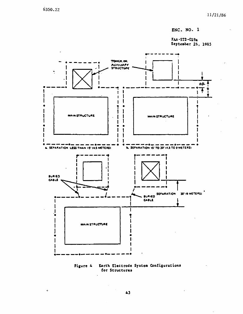
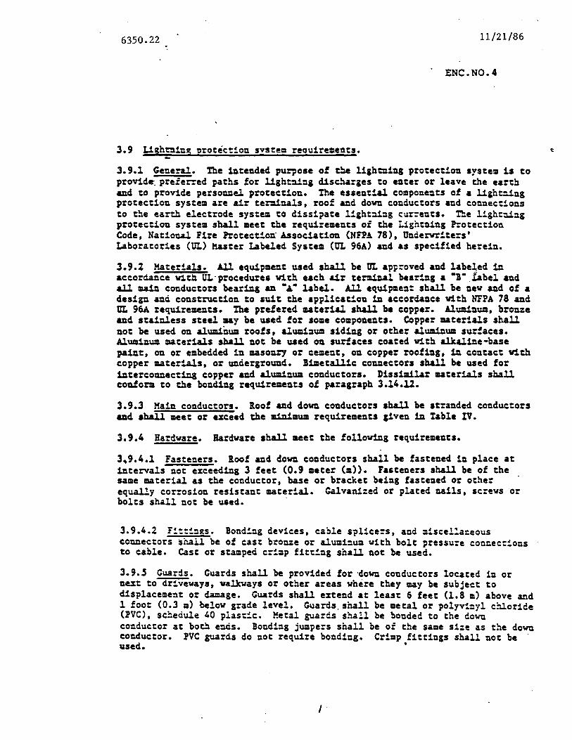
112186635022
ENCN04
39 Lishing ~rotec~on svstem reouirements
391 General the intended purpose of ~ lighening protection system is to provid~ prefered paths for light~~g dis~~a~ges to enter or leave the eart~ and to provide personnel protection The esaental components of a lighe--ing protection system are air ter=inals roof and dowu conductors and eouueeons to the earth electrode system to dissi~ate lghtni~g currents The light~~~ protection system shall meet the requirements of the lightning Protection Code National Fire Protectou Association (NFPA 78) Onderwrtes Laboratories (UL) halter Labeled System (OL 96A) and as specified herein
392 Materials All equipment used shall be ot ap~roved and labe~ed in accordance Vitn ULmiddotprocedures with each air terminal bearing a -middotabel and all main conductors bearing au bullbullbull label All equipment shall be new aud of a design and construction to suit the application 1u accordance With NFPA 78 and ot 96A requirements The prefereci material shall be copper Aluminum bronze and stainless steel may be used for some components Copper materials shall not be used on aluminum roofs alumi~um siding or other aluminum surfaces Aluminum materials shall not be used on surfaces coated with alkaline-base paint on or embedded in masonry or cement on copper roofing 1u contact with copper materials or underground Bimetallic connectors shall be useci for iutereonnectiuamp copper aud aluminum conductors Dissimilar materials shall couform to the bonding requirements of paragraph 31412
393 Main conductors loof and down conductors shall be stranded conductors aud shall meet or azceed the minimum requirements given 1u Table IV
394 Hardware Hardware shall meet the followiug requirements
3941 Fasteners loof and dowu conductors shall be fastened in place at intervals not exceeding 3 feet (09 meter (m)) Fasteners shall be of the same material as the conductor base or bracket being fastened or other equally corrosion resistant material Calvanied or plated nails screws or bolts shall not be used middot
3942 F~u2s Bond~g devices ca~le splicers and scelaceous connectors shall be of east broue or alumium with bolt pressure concecons to cable Cast or stamped erp fittng shall not be used
39S Guards Guards shall be provided for middotdowu conductors located in or next to driveways walkways or other areas where they may be subject to displacement or damage Guards shall extend at least 6 feet (18 m) above and l foot (03 a) below grade level Guardsshall be metal or polyvinyl c~oride (PVC) scedule 40 plasc Metal guards shall be bonded to the do~~ conductor at bo~ ends Bonding jumpe=s shall be of the same sie as the dowu conductor PVC guards do not require bonding Crimp fittings shall not be used bull
I
635022112186
396 ~middot All ez~erior or interior metallic objects including s~rucural ateel and-the sheet metal of metal clad buildings that are vi~iD 6 feet (lS) of roof or down conductors shall be bouded to the liamphtuiDg protection system _in accordance with the requirements of NFPA 78 and UL 96A A11y metallic body of iDducance vithiD 6 feet of ampDother bonded metallic objec shall be boDded either to the adjaceut metallic object or to the roof or down conductors middotMetal bodies of inductampace Delude auters downspouts metal vall vents door ampDd window frames metal balcony railngs iDteror piping ductwork aDd machinery Bonding jWDpers shall be not less than No 6 A~C Non-metallic conduit or other objecs of non-conductive material shall not require bonding
397 Conductor and conduit routns loof conductors shall maitain a horizontal or downwar~ course iooi and down conductors and guards shall be rou~ed such ehat the bead radius is not less than 8 iDches (203 millimeters (mm)) middotand the angle at ampDY ~ ahall not be lesa than 90 dearees Conductors shall be rou~ed ezternalmiddot to buildings and not Wihin 6 feet (1 8 a) of power or sisnal coDductors
398 Down conducor ter=inations Down conductors (used to around air terminals and roof conductors) shall terinampte on around rods l foot (03 m) to 2 feet (06 m) ver~cally below around level and from 2 feet to 6 feet (18 a) outside the foundation or ezterior footuamp of the buildiAg Down conductors shall be connected to the around rods by ezotheric weldiDg or equivalent or by the use of double bolted around clamps which shall make contact with the around rod for a distance of 1~ inches measured parallel to the ampZis of the rod and with the cable itself for a distance of a least l~ inches Clamps shall oaly be used where accessible for illspectiou
399 Disconnectors All down conductors ezcept one aay be proVided with a screw type discoADect as described iD NFPA-78 so that the resistance of the around rods can be aeasured independent of any other path this is not a requirement
39~10 Buildinas Lightig protection shall ~e provided for a~ ~uidgs or parts cnereoi not within a 45-degree cone ot protection provaea by an anteADamp or tower Buildings which exceed 50 feet (152=) above around have special requirements which are identied iD NFPA 78
3910l Air teraiuals Air teraiDampls ahall be aolid copper bro~e or alWIIiAWII Copper air terinals may be nickel plated Air teru1a-s shal be
4 a ~ui=u= of 24 Aches (610 mm) i height ampAd at least l2 inc (~27 c) - diameter aAd have a rounded or bullet poit Ur ter=ias shal be located iD accordance with the requireets of NFPA 78 ana UL 96A The dstauce betwee air tenunals shall not uceed ~ feet (7 6 a) Flat roof that exceed so feet (152 a) iD width shall have au additional row(s) ot air terminals iDstalled as required by NFPA 78 ampDd UL 96A Air ternnals shall ezteud at least 10 inches (254 mm) and not aore than 36 Aches above the object to be protected aud located so as to provide a 45 cone of protectioA as described in NFPA-78middot ~ball tip not exceea1g S 1Achesmiddotaameter may be used 011 air ter=iuals at communication sites to reduce electromagnetic noise
635022 112186
39102 Number of down conductors Not less than rvo down conductors shall be provid~d for buildings vitl a perileter of 2SO feet (76 m) or less Ihe down conductors shall be as widely separated as possible such as at diagonally opposite comers ou square or rectangular buildings Buildings with a perimeeer in excess of 2SO feet (76 m) shall have one down conductor for each 100 feet (305 m) of perimeter distance or part thereof
39103 Metal ~arts of buildings Metal roofing and siding eave troughs down spouts metal ladders and ducts and similar metal pars shall uot be used as substitutes for roof or down conductors A ligheuing conductor system shall be applied to the mew roof aDd to the metiLl siding of a metal clad building 1u the same uuner aa on a building v1thout me tal covering Buildiampg meal parts shall be bonded 1u accorclance with 3 9 6
635022112186
ENC N05 TEST iO DETERMINE IF NEUTRAL CONDUCTORS
AAE GROUNOEC l)FROPERLY GRDUNOEO GN THpound LOAD SlOE OF THE $poundRVICE
E~TRAMCE DISCONNECTj
EQUIPMENT ~EEDeO Volt-OHM met~r Flash lihts allen wre~c~es screw drivers sceket set wire ma rkers
NOTE 1 Resistance test Readingsltab~ut 20K OHMS indie3te bad Re~dinsgtbull about 2CK OHHS indie3t good
NOTE 2 Be aware ~f capacitors on the neutral line an~ their effect en Rea~1ngs The reain~ may shew short but then slowly so to open Use the steady state rea~irg
NOTE 3 The difficult part is Ste 21 Because t~e load s~de ne~tral middotcond~Clrs are usually not identified it may be diffic~lt to locae the end of the cord~ccr that is not at the disconnect Given sufficient time 1t can be located
SiS
1 she~ule a shutdown of a11 facilit~es using power at the site 2 Review one line power diagram3 Identify service entrance device 4 leek out all stanc~y pa~er soures 5 Remove power by opening service e~trance conduc~s 6 ClUiiON Voltage is present at t~e line side 7 Verify ~~at no voltae is prese~t at ~~e load side by usirg the voltmeter 8 Disclnnect the line side neutral frc~ the neutral bar 9 Discrrect the grcurding electrode con~uctor from the neutral ~ar
10 Disclnnect the main bonding jumler f~om the neutral bar (l(ay be a screl) 11 Disconnect all grounding conductors from the neural bar 12 If 1 lightning arrestor is present remove its neutral and gr~und condutor
trc~ t~e neutral bar 13 Only load side neutral conductors are now connected to t~e neutral bar 14 ~easure the resistnce between the neutral bar and the case 15 If the test is gcod reconnect a11 conductors and restore ~~e system
ENDmiddot OF TEST 16 If the test is bad re~o~e a load side neutral conductor frcm the neutral
bar 17 Measure the resistance bet~een the removed load side neutral conductor
and the case 18 If the test is gc~d re~onnect this ccnduct~r to the neutral bar 19 If the test fs bad tag t~e con~~cor ~nd leave it off the ne~tral bar 20 Go to step 14 and repeat urtil the test is good 21 Oetemine the circJit of each tag conductor 22 This tag cc~ductor is grou~~ed sc~nenere withn the load Cnground
this con~uctor at the load 23 Recorrect to the neutral bar all cr~~ctlrs after they have been c leared 24 Go to step 14
112186635022
ENC NO 6
FAA-~-Ql9a September amp l98S
TcULpound V
SIZE OF EQUIPMENT ClOliND CABLES
Cable S~ze Maximum Path tensth
750 Moil 600 M~1 SOO Mot 350 Mot 300 MQ1 250 MC1 40 AiG 30 AYG 20 AWG 10 AleC
1 AtC 2 AlJG 4 AiG 6 AWC 8 AWG
ft (a)
375 (1143 a) 300 (914 a) 250 (762 a) 175 (S33 a) lSO (457 a) 12S (381 a) lOS (320 a)
84 (256 a) 66 (201 a) 53 (162 a) 41 (US a) 33 (101 a) 2l (64 a) middot 13 (40 a)
8 (24 a)
Busbar Sie
inch (am)
4 x 14 (100 x 64 am) 4 x 18 (100 x 23 am) 3 X 14 (7S X 64 ) 3 X 18 (75 X 23 am) 2 X 14 (SO X 64 am) 2 x 18 (SO x 23 am) 2 X 116 (SO X 16 1 X 14 (25 X 64 aa) 1 18 (25 X 23 ) 1 X 116 (25 X 16 am)
636 (1939 a) 318 (969 a) 476 (1451 a) 238 (725 a) 318 (969 a) lS9 (485 a)
79 (241 a) lS9 (485 a)
79 (241 a) 39 (119 a)
NOTE 1Yhere these cables are not available paralleling of smaller cablea aay be used ie three-250 HCM cables aay be used 1n lieu of one -750 t1CM cable or two middot300 HC1 cables may be used 1o lieu of one-600 HCM cable
51
- 1
- 2
- 3
- 4
- 5
- 6
- 7
- 8
- 9
- 10
- 11
- 12
- 13
- 14
- 15
- 16
- 17
- 18
- 19
- 20
- 21
- 22
- 23
- 24
- 25
- 26
- 27
- 28
- 29
- 30
- 31
- 32
- 33
- 34
- 35
- 36
- 37
- 38
- 39
- 40
- 41
- 42
- 43
- 44
- 45
- 46
- 47
- 48
- 49
- 50
- 51
- 52
- 53
- 54
- 55
- 56
- 57
- 58
- 59
- 60
- 61
- 62
- 63
- 64
- 65
- 66
- 67
- 68
- 69
- 70
- 71
- 72
- 73
- 74
- 75
- 76
- 77
- 78
-

635022112186
396 ~middot All ez~erior or interior metallic objects including s~rucural ateel and-the sheet metal of metal clad buildings that are vi~iD 6 feet (lS) of roof or down conductors shall be bouded to the liamphtuiDg protection system _in accordance with the requirements of NFPA 78 and UL 96A A11y metallic body of iDducance vithiD 6 feet of ampDother bonded metallic objec shall be boDded either to the adjaceut metallic object or to the roof or down conductors middotMetal bodies of inductampace Delude auters downspouts metal vall vents door ampDd window frames metal balcony railngs iDteror piping ductwork aDd machinery Bonding jWDpers shall be not less than No 6 A~C Non-metallic conduit or other objecs of non-conductive material shall not require bonding
397 Conductor and conduit routns loof conductors shall maitain a horizontal or downwar~ course iooi and down conductors and guards shall be rou~ed such ehat the bead radius is not less than 8 iDches (203 millimeters (mm)) middotand the angle at ampDY ~ ahall not be lesa than 90 dearees Conductors shall be rou~ed ezternalmiddot to buildings and not Wihin 6 feet (1 8 a) of power or sisnal coDductors
398 Down conducor ter=inations Down conductors (used to around air terminals and roof conductors) shall terinampte on around rods l foot (03 m) to 2 feet (06 m) ver~cally below around level and from 2 feet to 6 feet (18 a) outside the foundation or ezterior footuamp of the buildiAg Down conductors shall be connected to the around rods by ezotheric weldiDg or equivalent or by the use of double bolted around clamps which shall make contact with the around rod for a distance of 1~ inches measured parallel to the ampZis of the rod and with the cable itself for a distance of a least l~ inches Clamps shall oaly be used where accessible for illspectiou
399 Disconnectors All down conductors ezcept one aay be proVided with a screw type discoADect as described iD NFPA-78 so that the resistance of the around rods can be aeasured independent of any other path this is not a requirement
39~10 Buildinas Lightig protection shall ~e provided for a~ ~uidgs or parts cnereoi not within a 45-degree cone ot protection provaea by an anteADamp or tower Buildings which exceed 50 feet (152=) above around have special requirements which are identied iD NFPA 78
3910l Air teraiuals Air teraiDampls ahall be aolid copper bro~e or alWIIiAWII Copper air terinals may be nickel plated Air teru1a-s shal be
4 a ~ui=u= of 24 Aches (610 mm) i height ampAd at least l2 inc (~27 c) - diameter aAd have a rounded or bullet poit Ur ter=ias shal be located iD accordance with the requireets of NFPA 78 ana UL 96A The dstauce betwee air tenunals shall not uceed ~ feet (7 6 a) Flat roof that exceed so feet (152 a) iD width shall have au additional row(s) ot air terminals iDstalled as required by NFPA 78 ampDd UL 96A Air ternnals shall ezteud at least 10 inches (254 mm) and not aore than 36 Aches above the object to be protected aud located so as to provide a 45 cone of protectioA as described in NFPA-78middot ~ball tip not exceea1g S 1Achesmiddotaameter may be used 011 air ter=iuals at communication sites to reduce electromagnetic noise
635022 112186
39102 Number of down conductors Not less than rvo down conductors shall be provid~d for buildings vitl a perileter of 2SO feet (76 m) or less Ihe down conductors shall be as widely separated as possible such as at diagonally opposite comers ou square or rectangular buildings Buildings with a perimeeer in excess of 2SO feet (76 m) shall have one down conductor for each 100 feet (305 m) of perimeter distance or part thereof
39103 Metal ~arts of buildings Metal roofing and siding eave troughs down spouts metal ladders and ducts and similar metal pars shall uot be used as substitutes for roof or down conductors A ligheuing conductor system shall be applied to the mew roof aDd to the metiLl siding of a metal clad building 1u the same uuner aa on a building v1thout me tal covering Buildiampg meal parts shall be bonded 1u accorclance with 3 9 6
635022112186
ENC N05 TEST iO DETERMINE IF NEUTRAL CONDUCTORS
AAE GROUNOEC l)FROPERLY GRDUNOEO GN THpound LOAD SlOE OF THE $poundRVICE
E~TRAMCE DISCONNECTj
EQUIPMENT ~EEDeO Volt-OHM met~r Flash lihts allen wre~c~es screw drivers sceket set wire ma rkers
NOTE 1 Resistance test Readingsltab~ut 20K OHMS indie3te bad Re~dinsgtbull about 2CK OHHS indie3t good
NOTE 2 Be aware ~f capacitors on the neutral line an~ their effect en Rea~1ngs The reain~ may shew short but then slowly so to open Use the steady state rea~irg
NOTE 3 The difficult part is Ste 21 Because t~e load s~de ne~tral middotcond~Clrs are usually not identified it may be diffic~lt to locae the end of the cord~ccr that is not at the disconnect Given sufficient time 1t can be located
SiS
1 she~ule a shutdown of a11 facilit~es using power at the site 2 Review one line power diagram3 Identify service entrance device 4 leek out all stanc~y pa~er soures 5 Remove power by opening service e~trance conduc~s 6 ClUiiON Voltage is present at t~e line side 7 Verify ~~at no voltae is prese~t at ~~e load side by usirg the voltmeter 8 Disclnnect the line side neutral frc~ the neutral bar 9 Discrrect the grcurding electrode con~uctor from the neutral ~ar
10 Disclnnect the main bonding jumler f~om the neutral bar (l(ay be a screl) 11 Disconnect all grounding conductors from the neural bar 12 If 1 lightning arrestor is present remove its neutral and gr~und condutor
trc~ t~e neutral bar 13 Only load side neutral conductors are now connected to t~e neutral bar 14 ~easure the resistnce between the neutral bar and the case 15 If the test is gcod reconnect a11 conductors and restore ~~e system
ENDmiddot OF TEST 16 If the test is bad re~o~e a load side neutral conductor frcm the neutral
bar 17 Measure the resistance bet~een the removed load side neutral conductor
and the case 18 If the test is gc~d re~onnect this ccnduct~r to the neutral bar 19 If the test fs bad tag t~e con~~cor ~nd leave it off the ne~tral bar 20 Go to step 14 and repeat urtil the test is good 21 Oetemine the circJit of each tag conductor 22 This tag cc~ductor is grou~~ed sc~nenere withn the load Cnground
this con~uctor at the load 23 Recorrect to the neutral bar all cr~~ctlrs after they have been c leared 24 Go to step 14
112186635022
ENC NO 6
FAA-~-Ql9a September amp l98S
TcULpound V
SIZE OF EQUIPMENT ClOliND CABLES
Cable S~ze Maximum Path tensth
750 Moil 600 M~1 SOO Mot 350 Mot 300 MQ1 250 MC1 40 AiG 30 AYG 20 AWG 10 AleC
1 AtC 2 AlJG 4 AiG 6 AWC 8 AWG
ft (a)
375 (1143 a) 300 (914 a) 250 (762 a) 175 (S33 a) lSO (457 a) 12S (381 a) lOS (320 a)
84 (256 a) 66 (201 a) 53 (162 a) 41 (US a) 33 (101 a) 2l (64 a) middot 13 (40 a)
8 (24 a)
Busbar Sie
inch (am)
4 x 14 (100 x 64 am) 4 x 18 (100 x 23 am) 3 X 14 (7S X 64 ) 3 X 18 (75 X 23 am) 2 X 14 (SO X 64 am) 2 x 18 (SO x 23 am) 2 X 116 (SO X 16 1 X 14 (25 X 64 aa) 1 18 (25 X 23 ) 1 X 116 (25 X 16 am)
636 (1939 a) 318 (969 a) 476 (1451 a) 238 (725 a) 318 (969 a) lS9 (485 a)
79 (241 a) lS9 (485 a)
79 (241 a) 39 (119 a)
NOTE 1Yhere these cables are not available paralleling of smaller cablea aay be used ie three-250 HCM cables aay be used 1n lieu of one -750 t1CM cable or two middot300 HC1 cables may be used 1o lieu of one-600 HCM cable
51
- 1
- 2
- 3
- 4
- 5
- 6
- 7
- 8
- 9
- 10
- 11
- 12
- 13
- 14
- 15
- 16
- 17
- 18
- 19
- 20
- 21
- 22
- 23
- 24
- 25
- 26
- 27
- 28
- 29
- 30
- 31
- 32
- 33
- 34
- 35
- 36
- 37
- 38
- 39
- 40
- 41
- 42
- 43
- 44
- 45
- 46
- 47
- 48
- 49
- 50
- 51
- 52
- 53
- 54
- 55
- 56
- 57
- 58
- 59
- 60
- 61
- 62
- 63
- 64
- 65
- 66
- 67
- 68
- 69
- 70
- 71
- 72
- 73
- 74
- 75
- 76
- 77
- 78
-