F/6 NATIONAL DAM INSPECTION PROGRAM. GUILFORO RESERVOIR ... · adao88 81 pummel kelepper and kahl...
56
ADAO88 81 PUMMEL KELEPPER AND KAHL BALTIMORE MD F/6 13/13 NATIONAL DAM INSPECTION PROGRAM. GUILFORO RESERVOIR NDI-ID-NUM--ETC(U) JUN 80 DACW31-80-I -0050 UNCLASSIFIED NL IIIEEIIEII
Transcript of F/6 NATIONAL DAM INSPECTION PROGRAM. GUILFORO RESERVOIR ... · adao88 81 pummel kelepper and kahl...

ADAO88 81 PUMMEL KELEPPER AND KAHL BALTIMORE MD F/6 13/13NATIONAL DAM INSPECTION PROGRAM. GUILFORO RESERVOIR NDI-ID-NUM--ETC(U)JUN 80 DACW31-80-I -0050
UNCLASSIFIED NL
IIIEEIIEII
326
II:IIII,__o
1111L25'8 11111"----iI ll _______ tIlhI!
MICROCOPY RLSOLU!ION UT (IHARI
L A .

STONY INN, BALTIMORE CITY
MARYLAND
DPJWM®MD WDo NDI ID OM 10
CITY OF BALTIMORE
PHASE I INSPECTION REPORT
NATIONAL DAM INSPECTION PROGRAM
Prepared ForDEPARTMENT OF THE ARMY
Baltimore District, Corps of EngineersBaltimore, Maryland 21203
By
V/ RUMMEL.KLEPPER & KAHL16jiCossouig Enginmeers
L.
coma ~ ~JUNE 1980 0oa
opIONtAL CONTAINS COLOR PLATEIS: ALL MC
REpRoDuCTIONS WILL SE IN SLACK AND WHITI.

' ''Z " - ' "" - "TT' .. ' ). .-- .... L -L -
(ttI .V Z ... _/ ., Ir .--sC-._
PATAPSCO RIVER BASIN
, TONY RUN. BA:,TPAORF CITY
MARYLAND
PHASE I INSPECTION REPORT "
NATIONAL DAM INSPECTION PROGRAM
, - Prepared for:
7/#' ...... DEPARTMENT OF THE ARMYBaltimore District, Corps of Engineers
Baltimore, aryland 21203
By:
RUMMEL, KLEPPER & KAHLConsulting Engineers1035 N. Calvert Street
Baltimore, Maryland 21202
June, 1980
'. gJ ----

PREFACE
This report is prepared under guidance contained in the RecommendedGuidelines for Safety Inspection of Dams, for Phase I Investigations.Copies of these guidelines may be obtained from the Department of theArmy, Office of Chief of Engineers, Washington, D.C. 20314.
The purpose of a Phase I investigation is to identify expeditiouslythose dams which may pose hazards to human life or property. Theassessment of the general condition of the dam is based upon visualobservations and review of available data. Detailed investigations andanalyses involving topographic mapping, subsurface investigations,material testing, and detailed computational evaluations are beyond thescope of a Phase I investigation; however, the ingpection is intended toidentify any need for such studies which should be performed by theowner.
In reviewing this report, it should be realized that the reported con-dition of the dam is based on observations of field conditions at thetime of inspection along with data available to the inspection team. Incases where the reservoir was lowered or drained prior to inspection,such action, while improving the stability of the dam, removes thenormal load on the structure and may obscure certain conditions whichmight otherwise be detectable if inspected under the normal operatingenvironment of the structure.
It is important to note that the condition of the dam depends on numer-ous and constantly changing internal and external factors which areevolutionary in nature. It would be incorrect to assume that thepresent condition of the dam will continue to represent the condition ofthe dam at some point in the future. Only through frequent inspectionscan unsafe conditions be detected and only through continued care andmaintenance can these conditions be prevented or corrected.
Phase I inspections are not intended to provide detailed hydrologic andhydraulic analyses. In accordance with the established Guidelines, thespillway design flood is based on the estimated "Probable MaximumFlood" for the region (greatest reasonably possible storm runoff), orfractions thereof. The spillway design flood provides a measure ofrelative spillway capacity and serves as an aid in determining the needfor more detailed hydrologic and hydraulic studies, considering thesize of the dam, its general condition and the downstream damage poten-tial.
The assessment of the conditions and recommendations was made by theconsulting engineer in accordance with generally and currently acceptedengineering principles and practices.

PATAPSCO RIVER BASINSTONY RUN, BALTIMORE CITY
MARYLAND
GUILFORD RESERVOIR
NDI ID NO. MD-106
CITY OF BALTIMOREDEPARTMENT OF PUBLIC WORKS
PHASE I INSPECTION REPORTNATIONAL DAM INSPECTION PROGRAM
June, 1980
CONTENTS
Description
SECTION I - Project Information 1SECTION 2 - Design Data 4SECTION 3 - Visual Inspection 6SECTION 4 - Operational Procedures 7SECTION 5 - Hydrology and Hydraulics 8SECTION 6 - Structural Stability 9SECTION 7 - Assessment, Recommendations, and
Proposed Remedial Measures 10
APPENDICES
Accssion ForAppendix Title NTIS G.AI
A Visual Inspection Checklist DD n AB
B Engineering Data Checklist Uh}natunco
C Photographs jwktbmi-- 60D Hydrology and HydraulicsE Plates By___F Geology _.ipution -
A_.LN~il nb11iitV Codes
Avall an~d/or
Dist speclal
Sii I- AL -_ _ _ _
- -1' - -..
PHASE I INSPECTION REPORTNATIONAL DAM INSPECTION PROGRAM
BRIEF ASSESSMENT OF GENERAL CONDITIONAND RECOMMENDED ACTION
Name of Dam: Guilford Reservoir
NDI ID No. MD-106Size: Small (134 acre-feet, 35 feet high)Hazard Classification: High
Owner: City of BaltimoreDepartment of Public Works600 Municipal Office BuildingBaltimore, Maryland 21202
State Located: MarylandCity Located: BaltimoreStream: Stony RunDate of Inspection: May 28, 1980
- Based on the visual inspection, available records, past opera-tional performance, and in accordance with the guideline criteria esta-blished for these studies, Guilford Reservoir is judged to be in goodcondition.
Cuilford Reservoir, a square-shaped impoundment is totally en-closed by an embankment which rises above the existing topography aroundits perimeter. Finished water from the Ashburton Water PurificationPlant is normally fed through the Baltimore City water transmissionsystem by gravity to the Guilford Reservoir. On occasion, flow to thereservoir is supplemented by pumpage from the Vernon Pumping Station.Water levels in the reservoir are generally maintained between eleva-tions 338 and 340.4. When the water level reaches elevati n 340.4,electrically operated butterfly valves are closed to stop inflow intothe reservoir. When the water demand has caused the reservoir level todrop 1 to 2 feet, the valves are opened to allow the reservoir to refill.
Because all inflow into the reservoir is controlled with the ex-ception of rainfall directly on the water surface, flood routing anddetailed hydraulic and hydrologic analyses are not required.
No embankment stability problems were evident at the time of theinspection, however surface erosion and a possible seepage area werenoted along the southern and southwest portions of the embankment.
4ii
.......................................
'A

P The following remedial measures are recommended to be accomplishedby the Owner:
1. Investigate the seepige area in the qouthwest corner of theembankment using either experienced in-house personnel or bycontract with a qualified engineering firm possessing geo-technical engineering expertisp. After investigatiorn, imple-ment recommended corrective measures to eliminate or contro!the seepage.
2. Repair the surface erosion located aling the southern por-tions of the embankment.
3. Expand the maintenance program to include regularly scheduloiinspections of the embankment and determine whether surfacperosion and/or future seepage is occuring and needs correc-tion.
4. Develop a formal warning system to alert the downslopo resi-
dents in the event of emergencies.
Submitted by:
RUMMEL, KLEPPER & KAHL
/ Edward J. Z.%lo 2 Associate
4NLDate: A .L j* _______________
I iApproved by:
AMES W. PECKolon, Corps of Engineers.istrict Engineer
ate:-, /
' iv
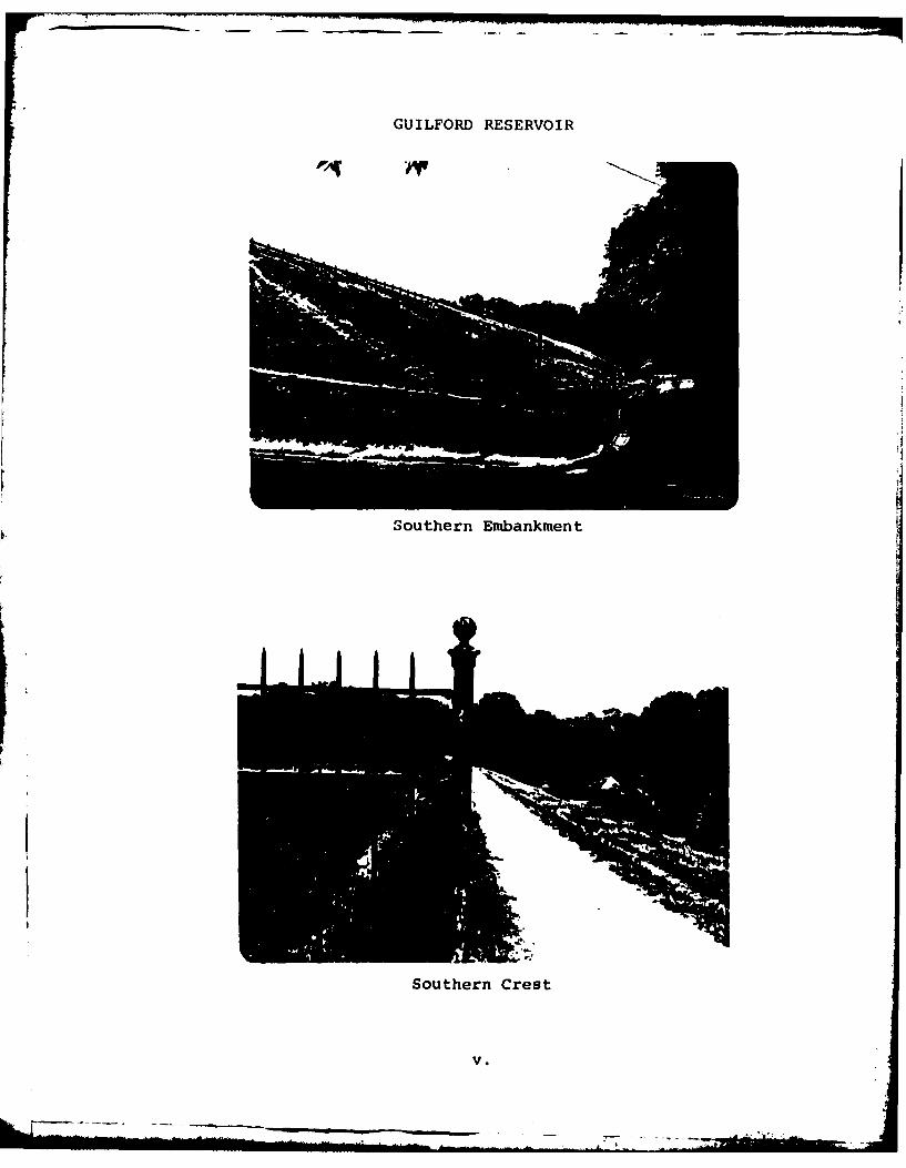
GUILFORD RESERVOIR
Southern Embankment
Southern Crest
V.

PHASE I INSPECTION REPORTNATIONAL DAM INSPECTION PROCRAM
GUILFORD RESERVOIRNDI ID NO. MD-106
SECTION IPROJECT INFORMATION
1.1 General.
a. Authority. The Dam Inspection Act, Public Law 92-367,authorized the Secretary of the Army, through the Corps ofEngineers, to initiate a program of inspection of damsthroughout the United States.
b. Purpose. The purpose of the dam inspection program is todetermine if the dam constitutes a hazard to human life orproperty.
1.2 Description of Projet.
a. Dam and Appurtenances. The Cuilford Reservoir, constructedin 1893, is a square shaped earthfill embankment. The im-poiindment is used for finished water storage and distributionfor the Baltimore City water supply. Inflow to and outflowfrom the reservoir are controlled by electrically ope'ratedbutterfly valves and the operating modes of the pumps in theGuilford Pumping Station, and the water level inside thereservoir is continuously recorded. Because all significantinflow into the reservoir is controlled, detailed hydraulicand hydrologic analyses have not been performed.
The various features of the dam and impoundment are shown onthe photographs in Appendix C and on the Plates in Appendix E.A description of the geology is included in Appendix F.
b. Location. The Guilford Reservoir is located in the Stony Rundrainage basin in Baltimore, Maryland. The reservoir isshown on U.S.G.S. Quadrangle, Baltimore East, Maryland, atlatitude N 390 20' 42" and longitude W 760 37' 00". A 1,a-tion map is included as Plate E-I.
c. Size Classification. Small (35 feet high, 134 acre-feet).
d. Hazard Classification. High hazard. Extensive residentia!development surrounds the impoundment.
e. Ownership. City of Baltimore, Department of Public Works,600 Minicipal Building, Baltimore, Maryland 2120?.

f. Purpose of Impoundment. Finished water storage for BaltimoreCity Water Distribution System.
g. Design and Construction History. Guilford Reservoir was con-structed in 1893. Construction drawings and design infor-mation are not available, however limited information on thetypical section of the embankment has been obtained from theCity of Baltimore.
h. Normal Operating Procedure. Finished water from the Ash-burton Water Purification Plant is fed through the BaltimoreCity water transmisstion system by gravity to the GuilfordReservoir. Water levels are generally maintained betweenelevations 338 and 340.4. When the water level in the reser-voir reaches elevation 340.4, electrically operated gatevalves are closed to stop inflow into the reservoir. When thewater demand has caused the water level to drop I to 2 feet,the gates are opened to allow the reservoir to fill.
1.3 Pertinent Data.
a. Drainage Area. Not applicable.
b. Discharge at Dam Site. Not applicable.
c. Elevation (Baltimore City Datum) (Feet).
Top of Dam 344.65 (low point on crest)Maximum Pool 341.4(overflow to storm drain)Normal Pool 338 to 340.4Upstream Invert Outlet Works Not ApplicableDownstream Invert Outlet Works Not ApplicableStreambed at Centerline of Dam Not ApplicableMaximum Tailwater Not AppicableDownstream Toe +310
d. Reservoir Length (Feet).
Normal Pool 550 (North to South)Maximum Pool 570 (North to South)
e. Storage (Acre-feet)
Normal Pool Level 104Maximum Pool Level 110Top of Dam 134
f. Reservoir Surface (Acres)
Normal Pool Level 7.0Maximum Pool Level 7.2Top of Dam 7.6
-2-
___ I! '~~
r i = . . . . . . -7 _ .. . . . . .2 . .'
. . . - - = ... . = - = , -. - - _ - -
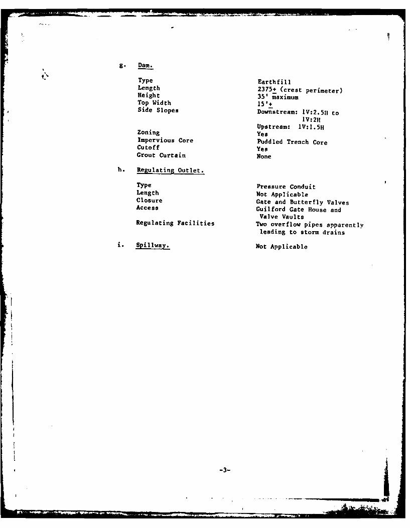
g. Dam.
Type EarthfillLength 2375+ (crest perimeter)Height 351 maximumTop Width 15'+Side Slopes Down-stream: IV:2.511 to
IV:2H
Upstream: IV:I.5HZoning YesImpervious Core Puddled Trench CoreCutoff YesGrout Curtain None
h. Regulating Outlet.
Type Pressure ConduitLength Not ApplicableClosure Gate and Butterfly ValvesAccess Guilford Gate House and
Valve VaultsRegulating Facilities Two overflow pipes apparently
leading to storm drains
i. Spillway. Not Applicable
-3-_ _

I Iwo,- -T
SECTION 2
DESIGN DATA
2.1 Design.
a. Data Available. With the exception of a typical section ofthe embankment and some construction drawings for reservoirinlet and outlet pipework obtained from the City of Balti-more, no data is available concerning the design or corstruc-tion of the Cuilford Reservoir.
(1) Hydrology and Hydraulics. No hydrologic or hydraulicdesign data is available. The records include a "Storage
Capacity vs. Elevation" curve for the reservoir, andpiping diagrams for the present operation of the reser-
voir.
(2) Embankment. With the exception of a typical section ofthe proposed embankment, no design information is avail-able for the embankment.
(3) Appurtenant Structures. Diagrams and some constructiondrawings are available for the system piping and inletand outlet facilities.
b. Design Features.
(I) Embankment. The typical section indicates that the em-bankment is constructed with earth fill and has a puddled
trench in the core of the embankment. The entire insideslope of the embankment is covered with stone riprap toretard erosion.
(2) Appurtenant Structures. Original design data is notavailable, but current piping diagrams and some pipeworkconstruction drawings have been provided by the City ofBaltimore, and a schematic piping diagram is included asPlate E-3.
c. Design Data.
(1) Hydrology and Hydraulics. No design data is available.A "Storage Capacity vs. Elevation" curve dated November17, 1927 has been obtained from the City of Baltimore anda tabulation derived from the Curve is included in Appen-dix D.
(2) Embankment. No design information is available for theembankment. A typical section of the embankment has beenobtnincd and is included in Appendix E.
-4-
Appendix

2.2 Construction. No data is available on the construction of the dam.
2.3 Operation. The reservoir is an active part of the Baltimore CityWater Distribution System. Presently, finished water from theAshburton Water Purification Plant is fed by gravity to the Guil-ford Reservoir. On occasions when the Ashburton plant filteringcapacity is limited, finished water is pumped from the VernonPumping Staticn which in turn is fed from the Montebello WaterPurification Plant. All inflow into the impoundment is controlledby valving in the inlet piping feeding the east and west sides ofthe reservoir. When the water level reaches elevation 340.4,electrically operated butterfly valves are closed to stop inflowinto the reservoir. When the water level has dropped from 1 to 2feet, the valves are opened and the reservoir allowed to refill.
2.4 Other Investigations. None reported.
2.5 Evaluation.
a. Availability. Design information on the embankment and ori-ginal hydraulics for the Guilford Reservoir are not avail-able.
b. Adeauacy. The available data is not sufficient to allow for atechnical assessment of the embankment. Current operatingprocedures are well documented and considered adequate toevaluate the hydraulic aspects of the Guilford Reservoir.
9
-5-J
4' ' '

SECTION 3VISUAL INSPECTION
3.1 Findings.
a. General. The on site inspection of the Guilford Reservoir
consisted of:
(1) Visual inspection of the embankment and embankment toe.
(2) Visual examination of the appurtenant structures.
(3) Evaluation of the hazard potential.
The specific observations are shown on Plate A-i.
b. Embankment. The general inspection of the embankment con-
sisted of a searching for indications of structural distress,such as cracks, subsidence, bulging, wet areas, seeps andboils, and observing general maintenance conditions, vegeta-
tive cover, erosion, and other surficial features. Saturated
soil was noted along the toe of the slope at the southwestcorner of the reservoir indicating a possible seepage area ora leak from a 48-inch water line approximately 30 feet down
slope from the seepage area. Surface erosion was noted along
the southern side of the reservoir, and an ero ion gully wasobserved near the eastern end of the top of the south embank-
ment.
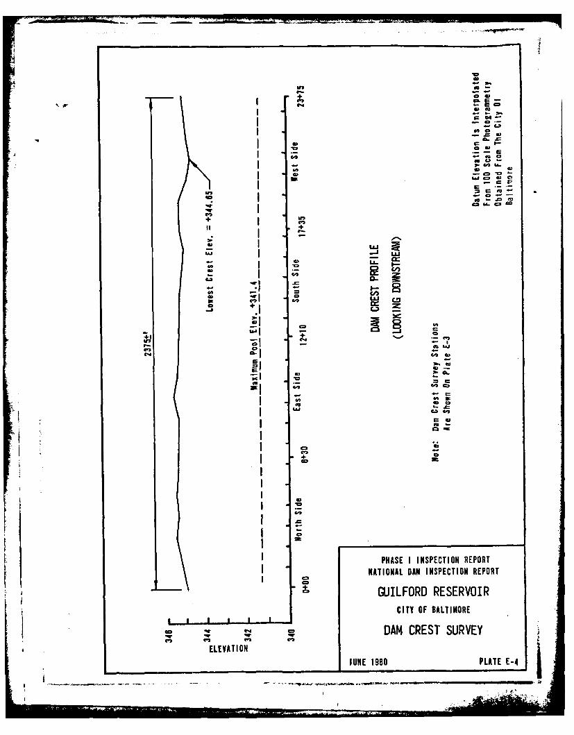
The crest of the embankment varies in elevation by approxi-
mately 11 inches. Freeboard at the time of the inspection wasapproximately 6 feet. The embankment crest profile is in-
cluded as Plate E-4.
c. Appurtenant Structures. The appurtenant structure consists
of a Gate House located in the east side of the impoundmentembankment and is in good condition.
d. Reservoir Area. The reservoir area consists solely of the
area within the embankment, and is in good condition.
e. Downstream Channel. Not applicable. The area surrounding
the reservoir consists of a residential community.
3.2 Evaluation. The visual examination and observations of the Guil-
ford Reservoir indicate that the reservoir is in generally good
condition with the exception of limited surface erosion and a
possible seepage area near the embankment toe at the southwest
corner. Investigations as to the cause of the seepage, are recom-
mended.
-6-
SECTION 4OPERATIONAL FEATURES
4.1 Procedure. Because the Guilford Reservoir forms an important partof the water distribution system for Baltimore City, the operationof the impoundment is well defined and continuous from day to day.
4.2 Maintenance of the Dam (Embankment). The maintenance of the em-bankment is considered fair. More attention should be given by theOwner to repairing surface erosion features as they occur. Thegrass cover is kept well mowed.
4.3 Maintenance of Operating Facilities. The city of Baltimore main-tains the mechanical and electrical equipment as required becauseof the importance of the reservoir to the City's Water distribu-tion system. Maintenance records for this equipment are availablefrom the Pumping Section, Bureau of Water and Waste Water, Balti-more City.
4.4 Warning System. No formal warning system exists for the reser-voir, however, reservoir levels are sensed by a pressure sensor onthe Guilford Pumping Station suction main and recordedcontinuously. Guilford Reservoir levels are also monitored on a24-hour basis at the central telemetering control center at theAshburton Water Purification Plant. Should it become necessary todrain the reservoir in the event of an emergency, inflow into thereservoir could be shut-off and the reservoir dewatered by usingthe two largest pumps in the Guilford Pumping Station. This couldbe accomplished within 19 hours based on a 45 million gallon perday pumping rate. Contract drawings for modifications to thereservoir inlet and outlet facilities indicate an existing 20-inchreservoir drain. Operating personnel do not know if the 20-inchdrain is still functional.
4.5 Evaluation. The maintenance of the operating equipment is good,and the maintenance of the embankment is fair. It is recommendedthat the Owner repair the surface erosion of the embankment andinvestigate the possible seepage zone at the embankment toe nearthe southwest corner.
-7-

SECTION 5HYDRAULICS AND HYDROLOGY
5.1 a. Evaluation of Features. Original design data for the hv'!ratiIics and hydrology of the Guilford Reservoir are not avai -able. Photocopies of "Storage Capacity vs. Elevation" cIrvwsfor the Guilford Reservoir have been obtained from the City o4
Baltimore. A tabulation of reservoir storage versi. poe'elevation is included as Page D-2 of Appendix D.
Because all inflow with the exception of rainfall on thesurface on the lake is controlled, hydrologic anl hvIrail'"analyses have not been performed for Guilford Reservoir. Thehazard classification for this small i mpounndment is co)nsider-ed to be high.
b. Experience Data. The reservoir water levels are monitored
utilizing a pressure sensor on the GuilforI Pumping qtationsuction main and automatically recorded continuously. Re-corded water levels are correlated with water level readingstaken from the reservoir staff gage once a week.
There is no information that would indicate that there hasever been a problem with Guilford Reservoir storing or pass-ing rainfall from severe storms including hurricanes.
c. Visual Observations. Visual examination of the embankmentand appurtenant structures indicate there are no problemswith the hydraulic and hydrologic aspects of Guilford Reser-voir.
d. Overtopping Potential. There is no evidence that potenti lovertopping is a problem. Inflow to the lake can be shut offby closing the electrically operated butterfly valves, one onthe 48-inch reservoir feeder and one on the 30-inch gate
house main. If lowering the reservoir level is necessary,water can be pumped from the reservoir through the Cuilfordpumping station. No evidence exists that Guilford Reservoirever overtopped or has been in danger of overtopping.
e. pq llwa__Adqiiy. There is no spillway for Guilford Peser-voir, but the existing effluent pipes are considered adrquatefor the manner in which the reservoir is operated. The twooverflow pipes with invert elevations of 341.4 apparentlylead to the Baltimore City storm drainage system and are
functional.
-8-.
, b_ _ _ _ __ _ _ _ _
SECTION 6STRUCTURAL STABILITY
6.1 Evaluation of Structural Stability
A. Visual Observations
(1) Embankment. As discussed in Section 3, there are nomajor deficiencies which may adversely affect thestability of the reservoir embankment at this time.
(2) Appurtenant Structures. The structural condition of the
appurtenant structures is considered to be satisfactory.
b. Design and Construction Data
(1) Embankment. What little data exists does not include anyquantitative data to aid in assessing the structuralstability of the dam. The old construction drawing show-ing a cross section of the embankment indicates that the
embankment has a puddled clay trench. No conditions wereobserved that would significantly affect the stability ofthe dam.
(2) Appurtenant Structures. Available information does notprovide adequate data to assess the structural adequacyof the appurtenant structures.
c. Operating Records. The structural stability of the dam isnot considered to be affected adversely by the operationalfeatures of the dam.
d. Post-Construction Changes. Some construction drawings areavailable showing the construction of a 72-inch tunnelthrough the west reservoir embankment for housing the 48-inchfinished water feeder. Limited drawings showing reservoirinlet/outlet piping modifications are also available.
e. Seismic Stability. Guilford Reservoir is located in Seismic
Zone 1; and, based on visual observation, the stability of
the dam appears to be adequate. The structure is presumed to
present no hazard from earthquakes.
-9-

SECTION 7ASSESSMENT AND RECOMMENDATIONS/REMEDIAL MEASURES
7.1 Dam Assessment
a. Assessment. The visual observations indicate that GuilfordReservoir is in satisfactory condition. A zone of saturatedsoil was noted along the toe of the slope of the southwestcorner of the reservoir, indicating a possible seepage area,but at this time it would not appear to be adversely affecting
embankment stability.
Because essentially all inflow into the reservoir can be con-
trolled, the hydraulic and hydrologic aspects of the projectare not significant.
b. Adequacy of Information. The available information on the
design and construction of Guilford Reservoir is limited.Because of the way the water levels are controlled, and be-cause of the fact that essentially no runoff enters the im-poundment, the available information is considered adequatefor the Phase I report.
c. Urgency. Although there is no urgency in instituting the
remedial measures recommended below except for theinvestigation of the seepage area, the measures should beimplemented in a timely manner.
d. Necessity of Additional Information. The Oner should in-
vestigate the seepage area in the southwest corner of theembankment to determine its source.
7.2 Recormmendation/Remedial Measures.
The following remedial measures are recommended to be accomplishedby the Owner:
a. Investigate the seepage area in the southwest corner of the
embankment using either experienced in-house personnel or bycontract with a qualified engineering firm possessing geo-technical engineering expertise. After investigation, imple-ment recommended corrective measures to eliminate or controlthe seepage.
b. Repair the surface erosion located along the southern
portions of the embankment.
c. Expand the maintenance program to include regularly scheduled
inspections of the embankment to determine whether surfaceerosion and/or future seepage is occuring and needs correc-tion.
-10-

d. Develop a formal warning system to alert the downsloperesidents in the event of emergencies.
I -11-

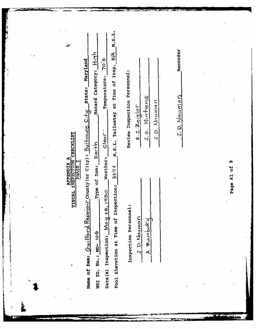
APPENDIX A
VISUAL INSPECTION CHECKLIST
PHASE I
i9
.14
'.4
$4$
04)0 0 0 0
Id0 -4 aj)41 Va 04 E4
0 0 0(AE-1 ~ 4 .' ( L) 5
41 04-
E-0
rq w
W~ coj 1
ZH > .
H H W . * '44a E-1U V) u 0
P40 ~ 0
H 0%
:1 04 04
~~ U)
C5 0 w)0 1.4
00 * 1 rj -4
3 *r4 V
0 00
... 04 *d U
z H >
44 a ~
V 0H0 0H
z Z 0 04

- a-
4- 46)
4*4
000
- 'I
ol U-s c -0
cU-1 0ul
5Z3I-40 0 4
c eau~
A 0 )zVwQ z
in 0 E-4 l

-4-U
Its0).
~
l~k -
zS~wo
E-1tz - I
+43-

0
00
0 4
PfH 0 H I
E-4)
S U) g
00
U) E-1
EnH
0 :3f
0

00
00
to P4
Atu
0H0
ta 4
II
000160

~44
00
aa0nza
I __ ____ _ _ ____ __ ____ _______ _ -A

o0,H E
0 H
C.CD
0~
U)~V 4-~~
040
ulc (n 2

C-4
0
0 0
H0
~~E-4
0 cu H
cn
~02 ad
- ---------

.3410
Upstream Slope Vt1.1
Slope Varies From IV to 2H1
Crest Width 15' 1
IPAS Zon INSPECTIOteREPORT
0 100' 200
VAISALBA INSPECTIONRGA
JUNE 1980 PLATE A-1

APPENDIX B
ENGINEERING DATA CHECKLIST
PHASE I

10~-
Li- 4--
0 0z
(J4 -,-
E-0
E-4
E-4~
V. o cj -S:
8e~ -t- I f
uzc
c E--
.E-4
~z
cn cn
04 0
H) I I-4I I
E- 0

0H .-- 0-q ¢
zD UDt5O
o oo
~~z P
11C = >
W H 0 ,-1
0 H-
LIa r"2

1 -
- -- j
44
L- C
I-DV Z cn
0~pa 77::
Qf-c
00
UZCI2 C)9 E-4
8 x
CO 00)
0 lz)
* 2: C r4

IQ
(Lr~
0
lo C.H
H H --- 0
C-'
0 0 to
00
H E- t
U 8 Z
EH H 0 U0tn U H ZtZ~C wnU E4 0O >4 Cw # 04C Z) H 0 0
Z-1 H H- H -4E0 9 .~ O E E-
Hn 34 U0 Z U UZI
E-4 0O wo 00w0404P
0_____ MI
APPENDIX C
PHOTOGRAPHS

339.7OLD COL SPRING LAH
c.U I L FO
39LFR0VNO
0IEt O~ t
OFlk TO~ $
Pa

GUILFORD RESERVOIR
A. Western Embankment - Crestand Downstream Slope
B. Eastern Embankment andGate House
C-I

GUILFORD RESERVOIR
C. Southern Embankment -
Downstream Slope
D. Northern Embankment-Downstream Slope
C-2

GUILFORD RESERVOIR
E. Riprap Slope Protection
F. Southwest Corner of Embankment-Saturated Soil at Toe where manstands,
C-3

GUITLFORD RESERVOIR
G. Erosion Gully at Top OfSouther Embankment
it. Erosion Has Exposed Soil onSouthern Embankment
C-4

APPENDIX D
HYDROLOGY AND HYDRAULICS
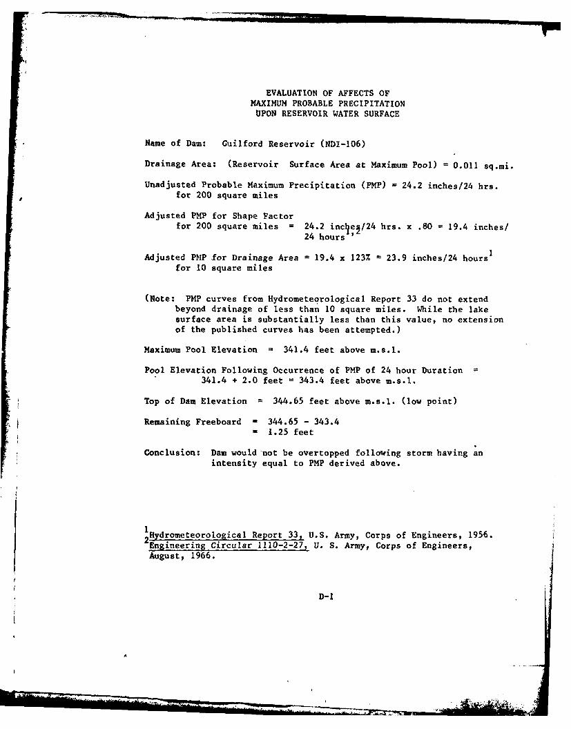
EVALUATION OF AFFECTS OF
MAXIMUM PROBABLE PRECIPITATIONUPON RESERVOIR WATER SURFACE
Name of Dam: Guilford Reservoir (NDI-106)
Drainage Area: (Reservoir Surface Area at Maximum Pool) = 0.011 sq.mi.
Unadjusted Probable Maximum Precipitation (PMP) = 24.2 inches/24 hrs.for 200 square miles
Adjusted PMP for Shape Factorfor 200 square miles = 24.2 inclei/ 24 hrs. x .80 = 19.4 inches/
24 hours '
Adjusted PMP for Drainage Area - 19.4 x 123% = 23.9 inches/24 hours
for 10 square miles
(Note: PMP curves from Hydrometeorological Report 33 do not extendbeyond drainage of less than 10 square miles. While the lakesurface area is substantially less than this value, no extensionof the published curves has been attempted.)
Maximum Pool Elevation = 341.4 feet above m.s.l.
Pool Elevation Following Occurrence of PMP of 24 hour Duration341.4 + 2.0 feet = 343.4 feet above m.s.l.
Top of Dam Elevation 344.65 feet above m.s.l. (low point)
Remaining Freeboard 344.65 - 343.41.25 feet
Conclusion: Dam would not be overtopped following storm having anintensity equal to PMP derived above.
SHdrometeorological Report 33, U.S. Army, Corps of Engineers, 1956.
Engineering Circular 1110-2-27, U. S. Army, Corps of Engineers,August, 1966.
D-1

Tabulation ofReservoir Storage Capacity Vs. Pool Elevation-
Name of Dam: Guilford Reservoir (NDI 106)
Pool Surface ReservoirElevation Area Storage
feet aove acres acre-feetm.s.l.
321.4 (Reservoir -
Bottom)
324 - 8
326 - 16
328 - 27
330 - 39
332 - 50
334 - 62
336 - 75
338 - 88
340 - 101
341.4 (MaximumPool) 7.2 110
344.65 (Top of Dam) 7.63 1344
ISource: Guilford Reservoir Capacity Curve, City of Baltimore,
Department of Public Works, Bureau of Water Supply, November 27,
2 1927.3 Baltimore Topographical Survey Datum
4Area computed from Baltimore City 100-scale photogrammetric mapping.
Computed by Rummel, Klepper & Kahl
D-2
W" Mai
APPENDIX E
PLATES

-~ ~ FAD ~ ~ ~~ Park , * -
C~pj11 1 a r
I J PROJECT
~~~ a J-. .,
1ti~ IN
1."Z'IKA
JD ~ ' 1 u ~'' 4 I4Y
wk ui o -t
-1 AT N9. HI j '
224 .,p!.. rkak_ ~ ,*Bi e~
w ig.
LeN. I
'4M'4 w -
oc!!:r K&~ CIFR EEVI
, 4 Scale 1" 2000-- - - r -
'.--pw P, I' lk teE,*,:rL..t ~ <~KN _____________________

LAAJ
-j C-
u-<
A Ej
C. 43CLC C2
w 11
63~
-- - toC3N

To Towso 4 th Zon~e-)
Orena tedl a Iaversk5l
7t~o Chlorinator
0 reoteLA MeC
so 30I'"burmon.IWIl-ePw~~ificcatione, PGn*NO T SAL
Via I VhjPLATE E-3l1-
00
00 u
Lna m
9-2-
-C.3
C-2~~ C.Ju c
I ..1
+ U+
II +
a
IHS I(NPETO4RPRNAINL A NSETONRPR
in "2ELEVATIO
JUNE ~ ~ ( 190PATJ-
AppENDIX-FGEOLOGY
GUILFORD RESERVOIR
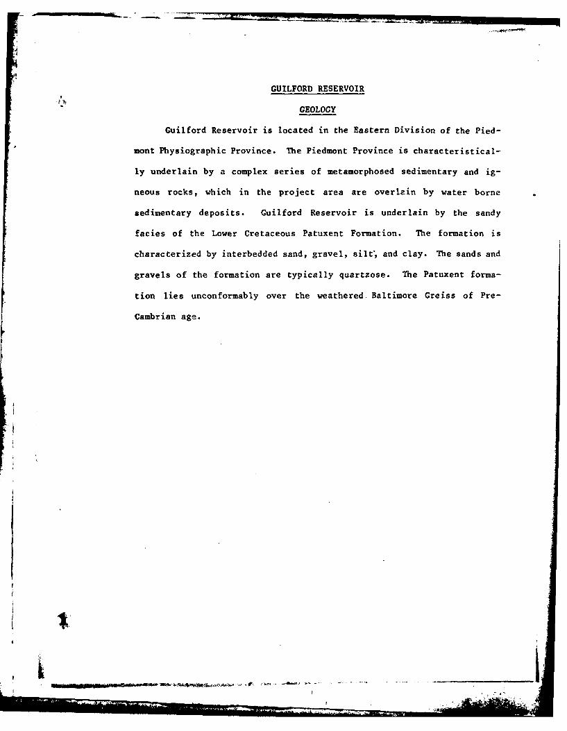
GEOLOGY
Guilford Reservoir is located in the Eastern Division of the Pied-
mont Physiographic Province. The Piedmont Province is characteristical-
ly underlain by a complex series of metamorphosed sedimentary and ig-
neous rocks, which in the project area are overlain by water borne
sedimentary deposits. Guilford Reservoir is underlain by the sandy
facies of the Lower Cretaceous Patuxent Formation. The formation is
characterized by interbedded sand, gravel, silt; and clay. The sands and
gravels of the formation are typically quartzose. The Patuxent forma-
tion lies unconformably over the weathered. Baltimore Greiss of Pre-
Cambrian age.
.9 .. I
po4
Pakrk
- IKe x 'J . "h
lie'
'Na ~ .~j it 8;h a
4e44AW
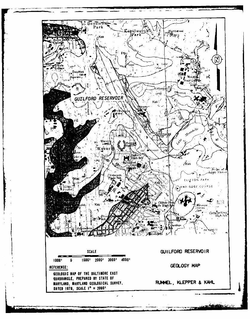
SCALOD ESGULRVOIRSEROIlOGO' 0 100' 200' 000'4000
REFERENCE: GEOLOY MA
GEOLGIC AP O THEDALTNOREEASQUADRNGLE PREARED Y STTE.OMARYLAND,~~~~~~~~ MAYADGOLGCLSREY UML LEPR&KH
DATE 199, CALEI" 000

.4 LEGEND
.P4
Artificial Fill Potomac Group(?Consists Of hleiroorneous materiats such asrock. unconsolida tedsrdimenst. sltop. refuse, and dredge spoil. Only major areas of nild Tese unconsolidated to Locistty won-oxide *,cemented sediments are
hihydisturbed round hatie been mapped, such as refilled pits. diked lith-ologicallty Siir to10 in on~o eduism~e
floo plains, an trnspotationi corirsIWNtpgrpe.t~ls elsewhere. Sediment capscopsdfsch atrlsredsrbtdaweas. Thsickneas 3 to 6 as (10 to 15 fli. discontinuously West of the intt Co ntrta. Paeqnce and havelntv
yielded PNIYRomorphs for Iostratagraphiccnrl.Cmo"toetthese we poorty to swell-sorted quartz Winds containing veriebleamounts Of seen quarts gravel. Veriablesamounts of milt and clay areconcentra ted in lenses or pods o, dissmiUnated 110 ewnrz. Thickness0.6 to J0 m to to 30 fit.
Qal
AlluviumI,, erbedded gravel. sand, milt. and cloy of varied compostion, andsorting. Typically confined id flood plains of perennial streams, upland 7gathering areas, end marshes adjacent to estuaries. Sediment size.sorting. and mineralogy are strongly controlled by. the source rocks andrgeomorphic setling The uartzose sands and polymict gravels are P 4typically well bedded and ocostlye compaceted; the silts ana clays are
oftn iate saurfed and poorly bedded. Minor amounts of cottuviumtunmappedl a interfinger uith eltuum at or near the bases of James Run Formationslopes. Structural symbols on alluvium represent bedrock exposures in
stemvlly.Tese are typicalty either along the margins of the flood (Carroll Gneiss Member)plain or close to the main channiel of the drainage. Thsickness 0.5 to Fine- to medium-grained. gen-s m IS to 16 ft. eraly lavered biotite-quarte-plo-
gmotsegIncus. locally with mu.cOvite. Mica absent and magne-tile present in some outcrops.Includes subordinate. concor-dant plasioclase-hormblendeones tamphibaite) in layers
geereally a few centimetergsto afwdecimeters thick, but locally
s much as several meters thick.-4 KxcConcorda plot yields are of 550
million years
Kxc- Kxs
Patuxent FormationKxS Sand facies. Highly variable. imterbedded sand, gravel, silte. and
clayconainig frruinous cements. Sand and gravel typicallyquartbose with a bu fkolinitic claNy-silt matrix. Sediments wreorenzed into flinguward packages 3 to S es (10 to 15 ft)
- thick consisting Of planar-bedded gravel with clay class, orcosbedded sandsr at the base grading upward to laminated or
massiv =itca at the top. Elsewhere vertical sequences showsabrupt seIn size changes and erosive contacts. The heasrymineral suite in characterized by stauralite. zircon. tourmaline.and kyanite. Spars silicified ansd abundant iron-oxide replace-ments of bath cvcadioids and coniferous wood are presentthroughout the Formation. These sediments were deposited in a
high-gradient, braided stream complex, mKxc Cloy faciers. Light grmy to black or brown clay containing, variable
amounts of quartz silt end giravel; local concentrations of lignstic.Partially jsyritized wood or macerated loaf end cone debris Wre Mount Washington Amphiboliteassoiatef with some sideritic concretiong, Thin planer, beda ofCheyunfrmdu-tsand and/or gOravly Clay Wre interbedded wsih nmiuz clays.These isolated cloy pods are thought to be accumulations on coarsegresned ainphiblithe con-defflted surfaces such Wabadoned stream channelsh or r- Biasing Of actiniosow moOwvatom topographic IDOLa tidadohrbe . Includes
mino massive actintolite, rock
R ENiCmEn . 3 a (7 to 115 ft). factenofelsl.
______GEOLOGY MAP LEGENDGEOOGI MA OFTHE BALTIMORE EAST
QUARANLEPREPARED BY STATE OFMRLNMARYLAND GEOLOGICAL SURVEY,R t4E , LE ER & K L
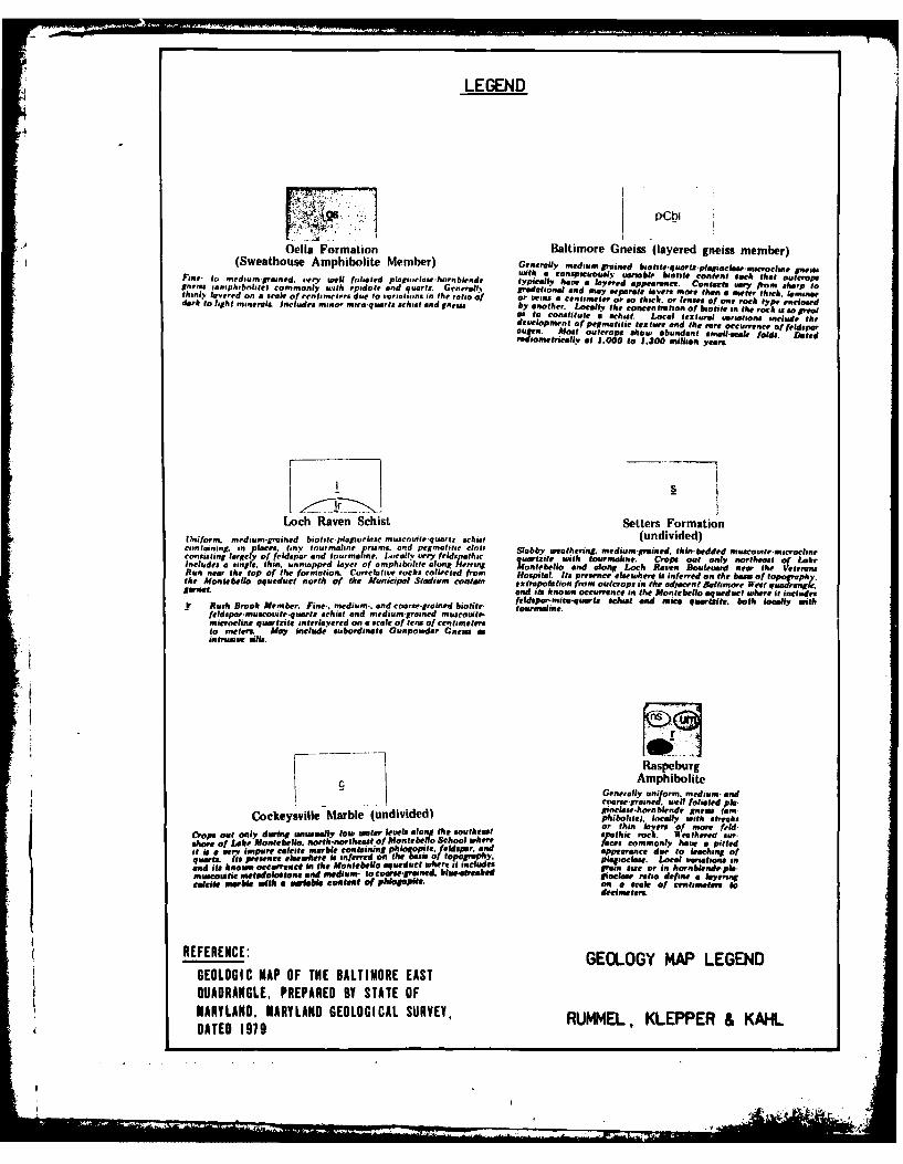
LEGEND
j P'CbI
AOcila Formation Baltimore Gneiss (layered gneiss member)
derk 0 t.ht min Amio li Member) Generally mdu-indbiotite.quart.pleioclasenuvromfn
Fie t edu-gand.orywllfligdplagiiorls-hru blende tpclyhva 4rdapean.Co tovry from sharp tanluoophboifl omony it eidleand qua~rtz. Geeet radelsonal admay separate laeers mnore thenna meter thick. lamose,aveed n scleof t. toviations in teriogf or twiliil a centimeter or so thicks. or lenses of one rock type enclosed= 0I~i'oir.s.Inlues m e-q sorts schist an nisby another. Loaolly file concentratison of hobte in the rock is &o greatm sto constitute a Behalf. Local gestlural variations include thedevelopment of pepmatelie texture and the rare occurrence of feldsparouesi. Most outcrops alhow abundant small-scale, fold. Dated
ousntiat of.000 to 1.300 million years.
Loch Raven Schist Setters FormationtUniform. medium-,rarned biotite plagiortagecmuscouite-quartz schist (undivided)containing. in flares, tiny tourmaline prisms. and pdeiiatitir clt Stubby weathering. medaasm-runed. thin-bedded muscouile-anacroelineconsisting largely of feldspar and toiurmaline. Locally very feldspathic urtite Miclh tourmialine. op ou oslnrtetofLeIncludes a single. thin, sin mapped layer of amphibutift ln I~ft o1~ n along LoH Ra= Bouleviard newr the VirteransRun near the top of the formation. .Correlative rocks collected from Hospital. Its presence elsewhere is inferred on the baing of topo phthe Mosutebeto aqueduct north of the Akrviic!PWl Stadium cimf estra polation from outcrops in the adjacent Balbsinore West ... Cg.PXJornet. and its known Occurrence in the Montebello aqueduct where it includes
feldspar-rmca-quawl, schust and mca qumitst. both locally withit Rush Brook Member. Fine,. medium-. and coarse-grained biotite lournline.fetdspar.muscovitt-quartz schist and medium-grained muscovile.microcline quartzite interlayered on a scale of tens of Miltlimet ersto meters. May include subordinate Gunpowder Cnew i -intrusive aills.
Raspeburg
Amphibolite
C Generally usniform. medium andCockeysville Marble (undivided) iolse) ho lnd spnem tan,unusall lo waer eves Ior thin layers 'of mnore felW
shore Of Loke Montebello. north-northeast of Monerbetf 0school where tcscmol aeapteit is a very impure cateste marble Containing phlo oite. feldspar, and appearance due to leeching of
qurt.igs presence elsewhere is inferred on the basi of topography. plpcae Local vwosations snqard tz nw odsacg h Montebello aqueduct where at includes =7sst o nhrnlnelmulproattic metadolostone and medium-,oos-rsd la~takdlo s ratio define a layerinCalcite marble with a wiabl Contant of phI0P00#on a scale Of centsrnatafs to
decimetler.
REFERENCE: GEOLOGY MAP LEGENDGEOLOGIC MAP OF THE BALTIMORE EASTQUADRANGLE, PREPARED BY STATE OFMARYLAND, MARYLAND GEOLOGICAL SURVEY, RUMMEL, KLEPPER & KAHLDATED 1979

LMED