F01U266055 01 GV4 AAC Guide - Home | Bosch...
30
en Approved Applications Compliance Guide Control Panels D9412GV4/D7412GV4/D7212GV4
Transcript of F01U266055 01 GV4 AAC Guide - Home | Bosch...

en Approved Applications Compliance Guide
Control Panels D9412GV4/D7412GV4/D7212GV4

GV4 Series | Approved Applications Compliance Guide | Listings and Approvals
GV4
2 Bosch Security Systems, Inc. | 3/12 | F01U266055-01
Listings and Approvals Fire
UL The D9412GV4 and D7412GV4 Control Panels are UL Listed for Central Station, Local, Auxiliary, Proprietary, and Household Fire Alarm.
Underwriters Laboratories, Inc. (UL) lists the D7212GV4 Control Panel as a Control Unit for Household Fire Warning.
The D7212GV4 is not UL Listed for Commercial Fire (UL864).
CSFM
The California State Fire Marshal (CSFM) approved the D9412GV4/D7412GV4/D7212GV4 Control Panel for Household Fire Warning.
The California State Fire Marshal (CSFM) approved the D9412GV4/D7412GV4 Control Panel for Fire Control Unit (Commercial).
Burglary UL
The D9412GV4/7412GV4/D7212GV4 Control Panels are UL listed for Central Station, Local, Police Station Connect, Holdup, Bank Safe and Vault, Mercantile Safe and Vault, and Household Burglar Alarm and Encrypted line Security when communicating via a network.
Department of Defense (DoD) The D9412GV4/D7412GV4 Control Panel was granted approval for Department of Defense (DoD) installations in Sensitive Compartmented Information Facilities (SCIF).
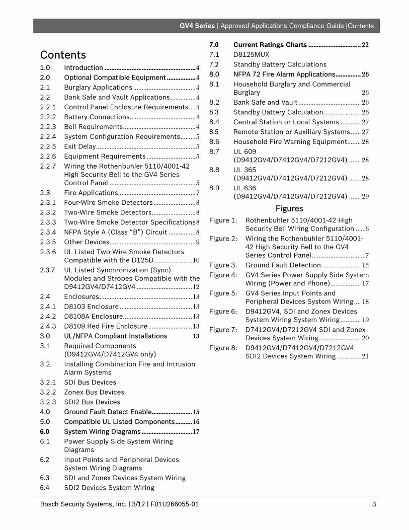
GV4 Series | Approved Applications Compliance Guide |Contents
.
Bosch Security Systems, Inc. | 3/12 | F01U266055-01 3
Contents 1.0 Introduction ...................................................... 4 2.0 Optional Compatible Equipment ................. 4 2.1 Burglary Applications ..................................... 4 2.2 Bank Safe and Vault Applications ............... 4 2.2.1 Control Panel Enclosure Requirements .... 4 2.2.2 Battery Connections ....................................... 4 2.2.3 Bell Requirements ........................................... 4 2.2.4 System Configuration Requirements ......... 5 2.2.5 Exit Delay ........................................................... 5 2.2.6 Equipment Requirements ............................. 5 2.2.7 Wiring the Rothenbuhler 5110/4001-42
High Security Bell to the GV4 Series Control Panel ................................................... 5
2.3 Fire Applications .............................................. 7 2.3.1 Four-Wire Smoke Detectors ......................... 8 2.3.2 Two-Wire Smoke Detectors .......................... 8 2.3.3 Two-Wire Smoke Detector Specifications 8 2.3.4 NFPA Style A (Class “B”) Circuit ................ 8 2.3.5 Other Devices ................................................... 9 2.3.6 UL Listed Two-Wire Smoke Detectors
Compatible with the D125B ....................... 10 2.3.7 UL Listed Synchronization (Sync)
Modules and Strobes Compatible with the D9412GV4/D7412GV4 ................................. 12
2.4 Enclosures ....................................................... 13 2.4.1 D8103 Enclosure ........................................... 13 2.4.2 D8108A Enclosure ......................................... 13 2.4.3 D8109 Red Fire Enclosure .......................... 13 3.0 UL/NFPA Compliant Installations 13 3.1 Required Components
(D9412GV4/D7412GV4 only) 3.2 Installing Combination Fire and Intrusion
Alarm Systems 3.2.1 SDI Bus Devices 3.2.2 Zonex Bus Devices 3.2.3 SDI2 Bus Devices 4.0 Ground Fault Detect Enable ........................ 15 5.0 Compatible UL Listed Components .......... 16 6.0 System Wiring Diagrams .............................. 17 6.1 Power Supply Side System Wiring
Diagrams 6.2 Input Points and Peripheral Devices
System Wiring Diagrams 6.3 SDI and Zonex Devices System Wiring 6.4 SDI2 Devices System Wiring
7.0 Current Ratings Charts ............................... 22 7.1 D8125MUX 7.2 Standby Battery Calculations 8.0 NFPA 72 Fire Alarm Applications ............... 26 8.1 Household Burglary and Commercial
Burglary 26 8.2 Bank Safe and Vault ..................................... 26 8.3 Standby Battery Calculation ...................... 26 8.4 Central Station or Local Systems ............ 27 8.5 Remote Station or Auxiliary Systems ...... 27 8.6 Household Fire Warning Equipment ........ 28 8.7 UL 609
(D9412GV4/D7412GV4/D7212GV4) ....... 28 8.8 UL 365
(D9412GV4/D7412GV4/D7212GV4) ....... 28 8.9 UL 636
(D9412GV4/D7412GV4/D7212GV4) ....... 29
Figures Figure 1: Rothenbuhler 5110/4001-42 High
Security Bell Wiring Configuration ..... 6 Figure 2: Wiring the Rothenbuhler 5110/4001-
42 High Security Bell to the GV4 Series Control Panel ............................... 7
Figure 3: Ground Fault Detection ....................... 15 Figure 4: GV4 Series Power Supply Side System
Wiring (Power and Phone) .................. 17 Figure 5: GV4 Series Input Points and
Peripheral Devices System Wiring .... 18 Figure 6: D9412GV4, SDI and Zonex Devices
System Wiring System Wiring ............ 19 Figure 7: D7412GV4/D7212GV4 SDI and Zonex
Devices System Wiring ......................... 20 Figure 8: D9412GV4/D7412GV4/D7212GV4
SDI2 Devices System Wiring .............. 21

D9412GV4/D7412GV4/D7212GV4 | Approved Applications Compliance Guide | 1.0 Introduction
4 Bosch Security Systems, Inc. | 3/12 | F01U266055-01
1.0 Introduction The UL System Chart (Table 3 on page 16) references the components that are evaluated and listed by UL for compatibility with the GV4 Series control panel. These components meet the basic system requirements for the applicable standard.
The System Wiring Diagrams, (refer to 6.0 System Wiring Diagrams on pages 17 to 21) show the relationship between the control panel and the accessory components referred to in Figure 4 on page 17.
2.0 Optional Compatible Equipment
UL Listed components not requiring evaluation for electrical compatibility can be used in many applications when installed according to the manufacturer’s instructions.
2.1 Burglary Applications UL Listed burglary alarm sensors not requiring evaluation for electrical compatibility can be used in burglary applications. In some cases, a UL Listed interface module must be used with the sensors. Consult the individual component specification and installation documents to determine suitability.
Test Weekly: UL Standard 1023 requires a weekly test for residential burglary applications.
2.2 Bank Safe and Vault Applications The UL Listed Model 5110 Bell and Model 4001-42 External Line Balancer (both made by Rothenbuhler) must be used for the bell and balanced line module in bank safe and vault applications. Modify the D8108A Attack-Resistant Enclosure to meet UL Standard 681.
2.2.1 Control Panel Enclosure Requirements
UL Standard 681 for Installation and Classification of Mercantile and Bank Burglary Alarm Systems requires foil lining or equivalent protection of the control unit enclosure. The D8108A Attack-Resistant Enclosure does not have a foil lining, but acceptable protection is provided by mounting electronic vibration sensors inside the enclosure. Refer to Figure 1 on page 6.
Do not use proximity alarms (capacitance) to protect the control panel enclosure.
Install the same electronic vibration sensors in the D8108A that are used to protect the safe or vault. Mount the Sentrol 5402, Potter EVD-S, or Arrowhead S-3810 electronic vibration detection (EVD) system inside the D8108A to meet the UL 681 requirements.
Mount the EVD sensor directly inside the metal cabinet of the D8108A as shown in Figure 1.
Do not install the EVD sensor within 6.4 mm (0.25 in.) of the components or traces of the printed circuit assembly.
Install and test the EVD sensor according to the manufacturer’s instructions.
2.2.2 Battery Connections
Using a D122 Dual Battery Harness, connect two 12 V batteries in the control panel enclosure. Refer to Figure 1 for battery placement information.
Use a separate D8108A for the 12 V batteries. When using a D122L Dual Battery Harness, wire the batteries in parallel and connect the harness to Terminals 4 and 5 of the control panel.
Auxiliary power, limited to 300 mA for 72 h, is required for standby.
2.2.3 Bell Requirements
Use the following Rothenbuhler bell and balanced line modules with the control panel: UL Listed Model 5110 Bell UL Listed Model 4001-42 External Line
Balancer

GV4 Series | Approved Applications Compliance Guide | 2.0 Optional Compatible Equipment
Bosch Security Systems, Inc. | 3/12 | F01U266055-01 5
Bell Test at Arming: UL Standard 365 requires a Bell Test at arming for bank safe and vault applications.
2.2.4 System Configuration Requirements
The following configuration and programming options are required for UL Bank Safe and Vault Systems. Refer to the D9412GV4/D7412GV4/D7212GV4 Program Entry Guide (P/N: F01U218312) for programming information.
Safe and Vault Protective Circuits
To test the devices that protect the safe(s) or vault(s) without sounding the bell, specify the devices’ points as controlled zones and supervised for trouble conditions. Refer to Point Index in the D9412GV4/D7412GV4/D7212GV4 Program Entry Guide (P/N: F01U218312) for more information.
Bell Configuration
UL 365 requires the bell time to be 15 to 30 min. The Rothenbuhler 5110 Bell provides selectable bell time through manipulation of its jumpers. Refer to the manufacturer’s installation instructions for more information.
In addition to the jumper settings inside the bell, you can activate the control panel for a bell time of 15 min.
UL 365 requires a Bell Test at arming and must be enabled in control panel programming.
Refer to Bell Parameters in the D9412GV4/D7412GV4/D7212GV4 Program Entry Guide (P/N: F01U218312) for more bell time and test programming information.
Bell Test
To enable the bell test feature, you enable an unused area of the control panel. Enable the bell test feature for the unused area only. Program Relay B as the area bell relay for the unused area.
All pass codes with authority to arm the safe or vault and also send a Closing Report must be valid in this area. Program the area for a five-second exit delay. Refer to Figure 1 on page 6 for test connections. To complete the installation for this feature, connect the output to a D133 Relay Module.
2.2.5 Exit Delay
The control panel’s programmed maximum exit delay must not exceed 30 sec.
2.2.6 Equipment Requirements GV4 Series Control Panel Two (2) D126 12 V, 7 Ah batteries Two (2) D1218 12 V 18 Ah batteries D8132 Battery Charger Module Two (2) D8108A Enclosures D122 Dual Battery Harness D122L Dual Battery Harness D133 Relay Module EVD System (Listed Safe/Vault) 2.2.7 Wiring the Rothenbuhler 5110/4001-42
High Security Bell to the GV4 Series Control Panel
Warning: Wear ear protection when installing and testing the Rothenbuhler High Security Bell.
Sound levels greater than 95 dBA at 3 m (10 ft) can occur.
1. Remove all power from the control panel. 2. Use six-conductor 1.2 mm (18 AWG) stranded
wire between the control panel and the 5110 Logic Board (located in the bell enclosure).
3. If you do not have a Silence switch, temporarily install a 1 resistor across TB1-1 and TB1-6 on the 5110 Logic Board. The resistor keeps the 5110’s bell silent during the installation and alignment procedures. Also place a temporary wire jumper across the TB1-6 Bell Relay and TB1-7. Refer to Figure 2 on page 7 for wiring a Silence switch.
4. Mount the D8108A’s 4001-42 External Balanced Line Module and wire it to the 5110 Logic Board using two-conductor 0.8 mm (22 AWG) cable.
5. Wire the 4001-42 to the control panel. Refer to Figure 2 and the Rothenbuhler installation manual.
6. Before supplying AC and DC power to the control panel and bell, ensure you are wearing ear protection. The bell sounds for 2 sec and then silences during power up.

D9412GV4/D7412GV4/D7212GV4 | Approved Applications Compliance Guide | 2.0 Optional Compatible Equipment
6 Bosch Security Systems, Inc. | 3/12 | F01U266055-01
Figure 1: Rothenbuhler 5110/4001-42 High Security Bell Wiring Configuration
0.64 mm (1/4 in.)minimum distance
+ - + -
17
3
14
1615
4
7
5
8
12
13
11
11 11
9
2
6
10 10
1 - Self-contained vibration sensor 2 - Control panel 3 - Accessory modules 4 - High line security module 5 - 4001-42 Balanced Line Module 6 - 5110 Bell 7 - D133 Relay 8 - Alarm zone input1 9 - D122 Battery Harness2
10 - D126 Battery 11 - D8108A Enclosure 12 - D122L Battery Harness2 13 - Proximity/control unit 14 - Normally open (NO) 15 - Normally closed (NC) 16 - End-of-line (EOL) resistor 17 - Safe
1 Use Terminal 11, 13, 14, 17, 19, 20, or 22. (Select only one.) 2 Use a D113 Battery Lead Supervision Module to supervise the battery connections.

GV4 Series | Approved Applications Compliance Guide | 2.0 Optional Compatible Equipment
Bosch Security Systems, Inc. | 3/12 | F01U266055-01 7
Figure 2: Wiring the Rothenbuhler 5110/4001-42 High Security Bell to the GV4 Series Control Panel
1
2
3
4
RED ORG WHT BL K
N/O 1
COMM 1
N/C 1
X1 -
X1+
7
9
1 2 3 6
1
2
3
4
5
6
7
10
11
13
8
9
12
6
3
9
9
1 - 5110 Logic Board 2 - 4001-42 External Line Balancing Module 3 - GV4 Series Control Panel 4 - Alarm output 5 - Alternate alarm 6 - Common 7 - +12 VDC
8 - Alarm zone input* 9 - 10 k resistor 10 - Optional Silence switch 11 - D133 Relay Module 12 - BBL In 4 13 - BBL Out 5 14 - Terminal TB1
* Use Terminal 11, 13, 14, 17, 19, 20, or 22. (Select only one.)
2.3 Fire Applications UL Listed fire initiating devices not requiring electrical compatibility evaluation can be used in any application. For example, the four-wire smoke detectors, heat detectors, waterflow switches, and manual pull stations are suitable fire initiating devices. Consult the individual component specification and installation documents to determine suitability.
The D7212GV4 is not UL Listed for Commercial Fire.
UL requires any device powered from a power output to be supervised.

| Approved Applications Compliance Guide | 2.0 Optional Compatible Equipment
8 Bosch Security Systems, Inc. | 3/12 | F01U266055-01
UL requires that power outputs are not shared between fire and non-fire devices unless all devices are in conduit within 20 ft and are in the same room (D9412GV4/D7412GV4).
2.3.1 Four-Wire Smoke Detectors
When using four-wire smoke detectors, install a power supervision device according to the manufacturer’s instructions. You can connect any number of four-wire smoke detectors to the GV4 Series Control Panels (subject to available auxiliary power).
The Reset Sensor command is available from the keypads when the Reset Sensor is enabled. Connect the smoke detectors to a suitable interface such as the D125B or D129, or to the D9127 Modules when used with a GV4 Series Control Panel. Smoke detectors can also be connected to the on-board points to meet UL and NFPA requirements.
When using four-wire smoke detectors, install a power supervision unit according to the manufacturer’s instructions. Refer to Section 2.3.5 Other Devices.
2.3.2 Two-Wire Smoke Detectors
Two-wire smoke detectors connect to the control panel only through the D125B Powered Loop Interface. Two-wire detectors must be evaluated for electrical compatibility, and be UL Listed for use with the control panel. Refer to Table 1 on page 10 for the two-wire smoke detectors that are UL Listed for compatibility and the maximum number of detectors that can be connected to each loop of the D125B Powered Loop Interface Module.
You can also consult the smoke detector manufacturer to determine if a particular smoke detector is UL Listed for use with the D9412GV4 and D7412GV4 Control Panels. The Reset Sensor command is available from the keypads when Reset Sensor is enabled.
2.3.3 Two-Wire Smoke Detector Specifications
Voltage Range: 8.0 VDC to 14 VDC UL Compatibility Identifier: Type A (for
control panel, detector, and base) 2.3.4 NFPA Style A (Class “B”) Circuit
Loops A and B on the D125B Module are NFPA Style A (Class “B”) initiating circuits suitable for connecting any fire alarm initiating device, including two-wire and four-wire smoke detectors. To connect initiating devices to on-board points (1 through 8) on the GV4 Series Control Panel: Use a D125B Powered Loop Interface
Module with two-wire initiating devices for a D9412GV4/D7412GV4/D7212GV4 Control Panel).
Use a D129 Dual Class “A” (NFPA Style D) Initiating Circuit Module with any type of initiating device, except a two-wire smoke detector.
Use the following guidelines when connecting fire alarm initiating devices to off-board points: Do not connect two-wire smoke detectors
to POPITs or MUX bus inputs.
Use the D9127U or D9127T POPIT Modules to connect four-wire smoke detectors when using a GV4 Series Control Panel.
Consult the UL Listed Two-Wire Smoke Detectors Compatible with the D125B section 2.3.6 to determine which product best fits your application.
The control panel does not support multiple detectors in alarm. The control panel is intended to handle detectors with optional features. Detectors from different manufacturers cannot be mixed on the same circuit.
The expansion bus can be shared between fire and non-fire devices where the POPIT module is providing data isolation between the input and the bus connections (D9412GV4/D7412GV4).

GV4 Series | Approved Applications Compliance Guide | 2.0 Optional Compatible Equipment
Bosch Security Systems, Inc. | 3/12 | F01U266055-01 9
2.3.5 Other Devices
Use a D130 Relay Module, D8129 OctoRelay, or Switched Aux (Terminal 8) to provide reset capability to other initiating devices such as: D125B Powered Loop Interface Module (2-
wire smoke detector module) D129 Dual “Class A” Initiation Circuit
Module (4-wire smoke detector) D9127T/U POPITs On-board points Install devices according to the manufacturer’s instructions. Refer to Off-Board Relays in the D9412GV4/D7412GV4/D7212GV4 Installation and Operation Guide (P/N: F01U201527).
For battery calculations, refer to Table 7 on page 24 and Section 8.0 NFPA 72 Fire Alarm Applications on page 26.
Test Weekly: Perform a Fire Test weekly. Both the AC power and battery are tested according to UL 864 (D9412GV4/D7412GV4/D7212GV4)

| Approved Applications Compliance Guide | 2.0 Optional Compatible Equipment
10 Bosch Security Systems, Inc. | 3/12 | F01U266055-01
2.3.6 UL Listed Two-Wire Smoke Detectors Compatible with the D125B
The D7212GV4 is not UL Listed for Commercial Fire (UL 864).
A D125B Powered Loop Interface Module is required to connect smoke detectors to the on-board points (1-8).
Table 1: UL Listed Two-Wire Smoke Detectors Compatible with the D125B
Manufacturer Detector Model Base Model
Maximum Number of Detectors per Loop
D125B
12 VDC 24 VDC1
Bosch Security Systems, Inc.
D262 D263 D263TH D263S D263THS D281 D282 D283 D285 D285DH D285TH D340 D286 D603 D604 D605 DS230 DS230F DS233F DS250 DS250TH DS260 DS282 DS282TH DS282S DS282THS DS290 F220P F220PTH F220PC F220PTHC F220-135 F220-135F F220-190F
D260 N/A N/A N/A N/A D280 D280 D280 D287, D288 D340 D287, D288 N/A D287, D288 D287, D288 D287, D288 D287, D288 MB2W, MB2WL MB2W, MB2WL MB2W, MB2WL MB2W, MB2WL MB2W, MB2WL MB2W, MB2WL N/A N/A N/A N/A N/A F220-B6 F220-B6 F220-B6 F220-B6 F220-B6 F220-B6 F220-B6
25 10 10 10 10 N/A N/A N/A 10 102
10 10 10 10 10 10 10 10 10 10 10 10 10 10 10 10 10 10 10 10 10 10 10 10
N/A 10 10 10 10 80 80 80 10 10 10 10 10 10 10 10 10 10 10 10 10 10 10 10 10 10 10 10 10 10 10 10 10 10
1 Requires a UL1481 regulated power-limited Power Supply. 2 Remote Test Station works only when used at 24 VDC.
The D7212GV4 is not UL Listed for Commercial Fire (UL 864).
GV4 Series | Approved Applications Compliance Guide | 2.0 Optional Compatible Equipment
Bosch Security Systems, Inc. | 3/12 | F01U266055-01 11
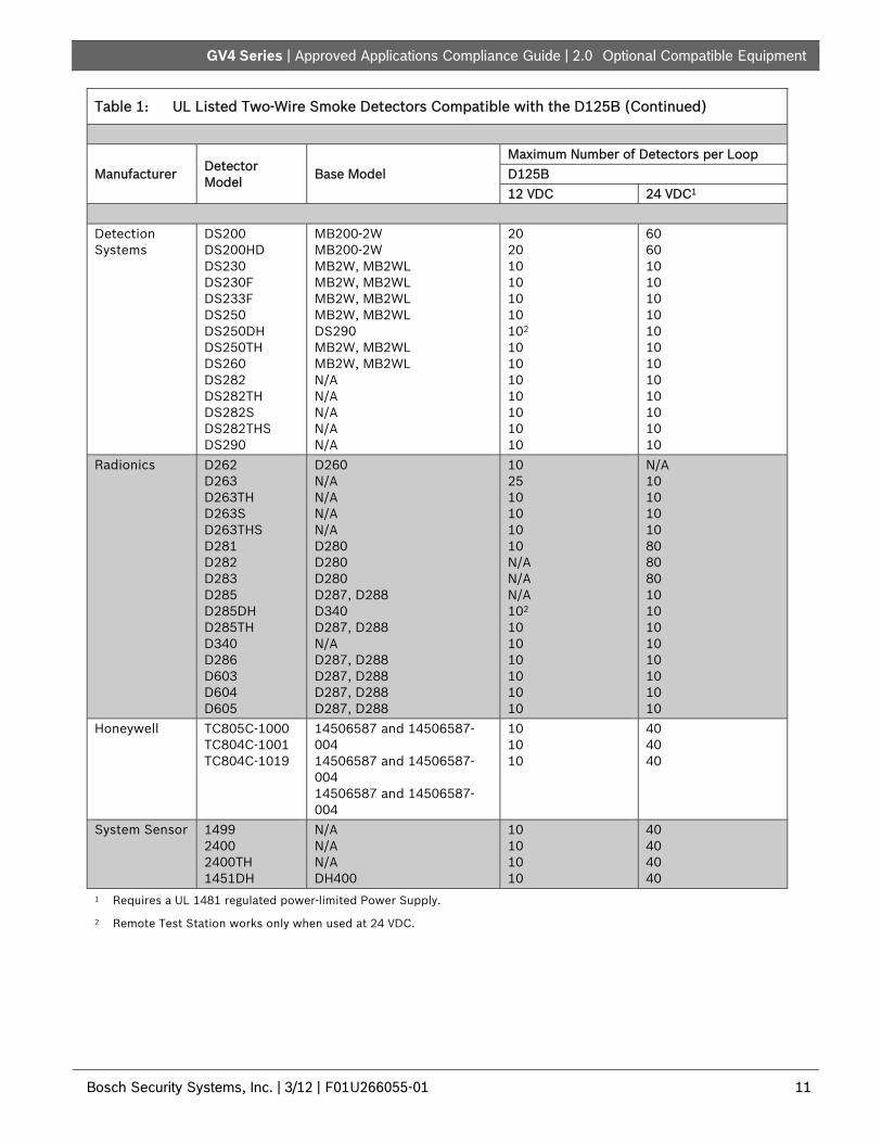
Table 1: UL Listed Two-Wire Smoke Detectors Compatible with the D125B (Continued)
Manufacturer Detector Model
Base Model Maximum Number of Detectors per Loop D125B 12 VDC 24 VDC1
Detection Systems
DS200 DS200HD DS230 DS230F DS233F DS250 DS250DH DS250TH DS260 DS282 DS282TH DS282S DS282THS DS290
MB200-2W MB200-2W MB2W, MB2WL MB2W, MB2WL MB2W, MB2WL MB2W, MB2WL DS290 MB2W, MB2WL MB2W, MB2WL N/A N/A N/A N/A N/A
20 20 10 10 10 10 102 10 10 10 10 10 10 10
60 60 10 10 10 10 10 10 10 10 10 10 10 10
Radionics D262 D263 D263TH D263S D263THS D281 D282 D283 D285 D285DH D285TH D340 D286 D603 D604 D605
D260 N/A N/A N/A N/A D280 D280 D280 D287, D288 D340 D287, D288 N/A D287, D288 D287, D288 D287, D288 D287, D288
10 25 10 10 10 10 N/A N/A N/A 102 10 10 10 10 10 10
N/A 10 10 10 10 80 80 80 10 10 10 10 10 10 10 10
Honeywell TC805C-1000 TC804C-1001 TC804C-1019
14506587 and 14506587-004 14506587 and 14506587-004 14506587 and 14506587-004
10 10 10
40 40 40
System Sensor 1499 2400 2400TH 1451DH
N/A N/A N/A DH400
10 10 10 10
40 40 40 40
1 Requires a UL 1481 regulated power-limited Power Supply.
2 Remote Test Station works only when used at 24 VDC.

| Approved Applications Compliance Guide | 2.0 Optional Compatible Equipment
12 Bosch Security Systems, Inc. | 3/12 | F01U266055-01
2.3.7 UL Listed Synchronization (Sync) Modules and Strobes Compatible with the D9412GV4/D7412GV4
To be UL 864 compliant, you must use only these models of synchronization modules and strobes with the D9412GV4 and D7412GV4 Control Panels.
The D7212GV4 is not UL Listed for Commercial Fire (UL 864).
Table 2: Synchronization Module and Strobe Compatibility
Manufacturer Synchronization Module Model Strobe Model
Input Power Source Candelas (cd)
Number of Strobes
System Sensor MDL S1224MC Control panel (12 VDC)
15 cd 8
External power supply (12 VDC)*
15 cd 23
External power supply (24 VDC)*
15 cd 50
110 cd 28
Wheelock DSM-12/24 RSS-121575-FW Control panel (12 VDC)*
15 cd 4
External power supply (12 VDC)*
12 cd 11
RSS-241575-FW External power supply (24 VDC)*
75 cd 33
* Requires a UL 1481 regulated power-limited Power Supply.

GV4 Series | Approved Applications Compliance Guide |
Bosch Security Systems, Inc. | 3/12 | F01U266055-01 13
2.4 Enclosures Bosch Security Systems offers three optional enclosures for the control panel. Sections 2.4.1 D8103 Enclosure, 2.4.2 D8108A Enclosure, and 2.4.3 D8109 Red Fire Enclosure describe the three options.
2.4.1 D8103 Enclosure
The D8103 is suitable for residential fire and burglary installations and commercial burglary applications that do not require attack resistance or the approval by Factory Mutual (FM) or New York City – Materials and Equipment Acceptance (NYC-MEA). Refer to Table 3 on page 16 for acceptable applications.
2.4.2 D8108A Enclosure
The D8108A is attack resistant and intended primarily for UL commercial burglar alarm and mercantile safe and vault applications requiring a local bell. This enclosure can be used in any burglar or fire alarm application where the D8109 Enclosure is suitable.
The D8108A, with some modification, can be used for bank safe and vault applications as described in Section 2.2 Bank Safe and Vault Applications on page 4. UL lists the D8108A for all commercial fire alarm applications. It is approved by FM, CSFM, and the NYC-MEA.
2.4.3 D8109 Red Fire Enclosure
Generally, the D8109 is used for fire alarm applications. UL lists the D8109 for all commercial fire alarm applications. It is approved by FM, CSFM, and the NYC-MEA.
All references to NFPA and related requirements are based on compliance with the NFPA 72, National Fire Alarm Code. Because installation specifications are generally based on a specific edition of a standard that was legally adopted by the authority having jurisdiction (AHJ), consult with the appropriate AHJ for confirmation.
3.0 UL/NFPA Compliant Installations
3.1 Required Components (D9412GV4/D7412GV4 only)
To install a D9412GV4 or D7412GV4 that is UL and NFPA compliant, the following items must be included: D8109 Red Fire Enclosure D192G Bell Supervision Module D928 Dual Phone Line Module D8004 Transformer Enclosure Ground Fault Detect enabled on the control
panel Refer to Table 3 on page 16 for specific application installation requirements.
3.2 Installing Combination Fire and Intrusion Alarm Systems
When installing a combination fire and intrusion alarm system, you must adhere to the following requirements in order to comply with Sections 56.1, 56.2, and 56.4 of the 9th Edition of UL 864.
The D7212GV4 is not listed for commercial fire applications.
3.2.1 SDI Bus Devices
Keypads (Command Centers)
Keypads used exclusively for intrusion system operation are not allowed. Keypads connected to the D9412GV4 and D7412GV4 Control Panels must include the scope of all fire-related points and must be assigned to include Area 1 in the scope.
Interface Modules Connect the DX4020 Network Interface
Module and the D9210C Access Control Interface Module to the SDI bus only if the interface module is located within the control panel enclosure or in a separate enclosure in the same room within 6.1 m (20 ft) of the main control panel.
Route all SDI bus wiring in EMT (electrical metallic tubing) conduit.

| Approved Applications Compliance Guide | 3.0 UL/NFPA Compliant Installations
14 Bosch Security Systems, Inc. | 3/12 | F01U266055-01
3.2.2 Zonex Bus Devices
D8125 POPEX Modules The expansion bus can be shared between fire and non-fire devices where the POPIT module provides data isolation between the input and the bus connections. D8125MUX Multiplex Interface Modules When connecting a D8125MUX module to
Zonex Bus 1 or 2, all multiplex modules should supervise only all fire or all non-fire devices.
Do not connect fire and non-fire devices to the same D8125MUX module.
Using Zonex Bus 1 exclusively for fire devices and Zonex Bus 2 exclusively for non-fire devices is acceptable.
D8128D OctoPOPIT Modules Do not connect fire and non-fire devices to
the same D8128D OctoPOPIT Module. Using Zonex Bus 1 exclusively for fire devices
and Zonex Bus 2 exclusively for non-fire devices is acceptable.
Install all D8128D OctoPOPIT Modules used for fire devices within the control panel enclosure or in a separate enclosure in the same room within 6.1 m (20 ft) of the main control panel.
Route all Zonex bus wiring in EMT (electrical metallic tubing) conduit.
For system supervision, do not use looped wire terminals.
D8129 Octo-relay Modules If any fire devices are connected to Zonex Bus
1 (or Zonex Bus 2), you must use all D8129 OctoRelay Modules connected to Zonex Bus 1 (or Zonex Bus 2) only for fire applications.
Install all D8129 OctoRelay Modules used for fire devices within the control panel enclosure or in a separate enclosure in the same room within 1.52 m (5 ft) of the main control panel.
Route all Zonex bus wiring in EMT (electrical metallic tubing) conduit.
3.2.3 SDI2 Bus Devices
GV4 Series Control Panels can support a number of accessory devices from the SDI2 Bus using Terminals 33 through 36. Some devices include the B208 Octo-input Module, the B308 Octo-output Module, and the B820 SDI2 Inovonics Interface Module.
B208 Octo-input Module Do not connect fire and non-fire devices to
the same B208 Octo-input Module. B208 Octo-input module is fully supervised. B308 Octo-output Module Do not connect fire and non-fire devices to
the same B308 Octo-input Module.
GV4 Series | Approved Applications Compliance Guide | 4.0 Ground Fault Detect Enable
Bosch Security Systems, Inc. | 3/12 | F01U266055-01 15
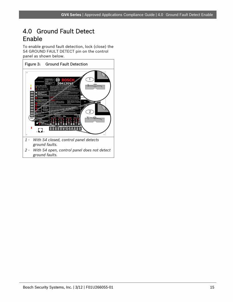
4.0 Ground Fault Detect Enable To enable ground fault detection, lock (close) the S4 GROUND FAULT DETECT pin on the control panel as shown below.
Figure 3: Ground Fault Detection
1 - With S4 closed, control panel detects
ground faults. 2 - With S4 open, control panel does not detect
ground faults.

| Approved Applications Compliance Guide | 5.0 Compatible UL Listed Components
16 Bosch Security Systems, Inc. | 3/12 | F01U266055-01
5.0 Compatible UL Listed Components In Table 3, the text in the columns and rows for GV4 Series Control Panel have the following meanings:
No = Not acceptable for this application
Req. = Required for this application
Opt. = Optional for this application.
[Empty box] = Not used for this application
Table 3: UL Listed Components Compatible with the GV4 Series Control Panels
Hou
seho
ld B
urgl
ary
Hou
seho
ld F
ire
Hou
seho
ld F
ire/
Bur
glar
y C
ombi
ned
Cen
tral
Sta
tion
Bur
glar
y
Pol
ice
Con
nect
ed
Bur
glar
y
Loca
l Bur
glar
y
Loca
l Fire
/Bur
glar
y C
ombi
ned
D94
12G
V4/
D74
12G
V4
Loca
l Fire
D
9412
GV
4/D
7412
GV
4
Loca
l and
Cen
tral
S
tatio
n F
ire C
ombi
ned
D94
12G
V4/
D74
12G
V4
Loca
l and
Cen
tral
S
tatio
n F
ire/
Bur
glar
y
D94
12G
V4/
D74
12G
V4
Cen
tral
Sta
tion
Fire
/ B
urgl
ary
Com
bine
d
D94
12G
V4/
D74
12G
V4
Cen
tral
Sta
tion
Fire
D94
12G
V4/
D74
12G
V4
Ele
ctric
ally
Act
uate
d T
rans
mitt
er
D94
12G
V4/
D74
12G
V4
Minimum Hours of Standby Battery 4 24 + 4 min alarm 4 4 4 24 + 5 min alarm
D8103/D8109 Enclosure Opt. Opt. Opt. Opt. No Opt. No Opt. Opt. No No Opt. No
D8108A Enclosure Opt. Opt. Opt. Opt. Req. Opt.. Req. Opt. Opt. Req. Req. Opt. Opt.
D125B Class B, Style A Powered Loop Interface*
Opt. Opt. Opt. Opt. Opt. Opt. Opt. Opt. Opt. Opt. Opt. Opt. Opt.
D129 Class A, Style D Initiating Module* Opt. Opt. Opt. Opt. Opt. Opt. Opt. Opt. Opt. Opt. Opt. Opt. Opt.
D928 Dual Phone Line Module** Opt. Opt. Opt. Opt. Opt. Opt. Required if using two telephone lines for communication.
D192G Class “B”, Style Y Bell Circuit Supervision
Opt. Opt. Opt. Opt. Opt. Opt. Req. Req. Req. Req. Req. Req.
D268/D269H Independent Zone Control Optional. Only connect to Zones 1 to 8. No No No No No No No
DS7432 Eight Input Remote Module Opt. Opt. Opt. Opt. Opt. Opt. Opt. Opt. Opt. Opt. Opt. Opt.
DS7457iF Single Zone Input Module Opt. Opt. Opt. Opt. Opt. Opt. Opt. Opt. Opt. Opt. Opt. Opt.
DS7560i Dual Zone Input Module Opt. Opt. Opt. Opt. Opt. Opt. Opt. Opt. Opt. Opt. Opt. Opt.
DS7461i Single Zone Input Module Opt. Opt. Opt. Opt. Opt. Opt. Opt. Opt. Opt. Opt. Opt. Opt.
DS7465i Input/Output Module Opt. Opt. Opt. Opt. Opt. Opt. Opt. Opt. Opt. Opt. Opt. Opt.
B208 Octo-input Module Opt. Opt. Opt. Opt. Opt. Opt. Opt. Opt. Opt. Opt. Opt. Opt. Opt.
B308 Octo-output Module Opt. Opt. Opt. Opt. Opt. Opt. Opt. Opt. Opt. Opt. Opt. Opt. Opt.
B420 Ethernet Communication Module Opt. Opt. Opt. Opt. Opt. Opt. Opt. Opt. Opt. Opt. Opt. Opt. Opt.
DX4020 Network Interface Module Opt. Opt. Opt. Opt. Opt. Opt. Opt. Opt. Opt. Opt. Opt. Opt. Opt.
ITS-DX4020-G Network Interface Module Opt. Opt. Opt. Opt. Opt. Opt. Opt. Opt. Opt. Opt. Opt. Opt. Opt.
B820 Inovonics Interface Module Opt. Opt. Opt. Opt. Opt. Opt. NA NA NA NA NA NA NA
D130 Relay Module Opt. Opt. Opt. Opt. Opt. Opt. Opt. Opt. Opt. Opt. Opt. Opt.
D1255 and D1260 Keypads Opt. Opt. Opt. Opt. Opt. Opt. No No No No No No No
D1256 Command Center and D1257 Annunciator
Opt. Opt. Opt. Opt. Opt. Opt. No No No No No No No
D1255B and D1260B Keypads Opt. Opt. Opt. Opt. Opt. Opt. No No No No No No No
D1255RB, D1256RB, D1257RB No Opt. Opt. No No No Req. Req. Req. Req. Req. Req.
D1640 Transformer Required for all applications.
D8004 Transformer Enclosure Opt. Opt. Opt. Opt. Opt. Opt. Req. Req. Req. Req. Req. Req.
D8125 Class B, Style 4.0 POPEX Module Required for the D9127T/U POPITs.
D8125MUX Class B, Style 4.0 Required for MUX devices. Refer to Section 7.1 D8125MUX on page 22.
D9127T/U Class B, Style A POPIT Modules Opt. Opt. Opt. Opt. Opt. Opt. Opt. Opt. Opt. Opt. Opt. Opt.
D8128D OctoPOPIT Opt. Opt. Opt. Opt. Opt. Opt. Opt. Opt. Opt. Opt. Opt. Opt. Opt.
D8129 OctoRelay Optional. For remote annunciation of system functions.
D8130 Release Module Opt. Opt. Opt. Opt. Opt. Opt. Opt. Opt. Opt. Opt. Opt. Opt. Opt.
D8132 Battery Charger Refer to Table 7: Current Rating Chart for Standby Battery Calculations
No No No No No No No
D9131A Parallel Printer Interface Opt. Opt. Opt. Opt. Opt. Opt. Opt. Opt. Opt. Opt. Opt. Opt. Opt.
D9210C Access Control Interface** Opt. Opt. Opt. Opt. Opt. Opt. Opt. Opt. Opt. Opt. Opt. Opt. No
* The D125B is required to connect two-wire fire alarm initiating devices. The D125B provides two powered loops for connecting listed two-wire smoke detectors. The D129 provides two non-powered Class “A” initiating circuits.
** Applicable to the D9412GV4 and D7412GV4 Control Panels only.

GV4 Series | Approved Applications Compliance Guide | 6.0 System Wiring Diagrams
Bosch Security Systems, Inc. | 3/12 | F01U266055-01 17
6.0 System Wiring Diagrams The System Wiring Diagrams, (refer to Figure 4: GV4 Series Power Supply Side System Wiring (Power and Phone) on page 17 to show the relationship between the control panel and the accessory components referred to in Table 3 on page 16).
6.1 Power Supply Side System Wiring Diagrams
All external connections except Terminal 5 (battery positive) are power limited.
Figure 4: GV4 Series Power Supply Side System Wiring (Power and Phone)
1 - If required by local AHJ, connect D113 Battery Lead Supervision Module.
2 - Batteries 3 - D122/D122L Dual Battery Harness, as required 4 - D1640 Transformer and D8004 Transformer
Enclosure required for NFPA Applications 5 - D8132 Dual Battery Charger with two batteries
(Batteries are not supervised.) 6 - D192G Bell Supervision Module 7 - To Relay A or Relay B
8 - Listed Audible Signaling Devices rated at 12.0 VDC nominal (do not use vibrating
type horns) 9 - C900V2(optional) 10 - RJ31X, secondary phone line (not available on
the D7212GV4) 11 - 560 Ω, 2 W EOL Resistor
(P/N: 15-03130-005) 12 - RJ31X, primary phone line 13 - D928 (not available on the D7212GV4) 14 - To earth ground
Terminals 1, 2, and 11, and the Accessory Connector are power limited, supervised.
All external connections except Terminal 5 (battery positive) are power limited.

| Approved Applications Compliance Guide | 6.0 System Wiring Diagrams
18 Bosch Security Systems, Inc. | 3/12 | F01U266055-01
6.2 Input Points and Peripheral Devices System Wiring Diagrams
Figure 5: GV4 Series Input Points and Peripheral Devices System Wiring
1 - (Optional): For 24 V applications use a UL 1481
listed, regulated, power-limited 24 VDC power supply with a D130 Relay Module. Refer to the D130 Installation Instructions (P/N: F01U072455) for correct wiring requirements.
2 - D130 Relay Module 3 - D125B Powered Loop Interface Module 4 - To UL Listed two-wire smoke detectors with a fire
rated EOL resistor. Refer to Two-Wire Smoke Detectors in the D9412GV4/D7412GV4/D7212GV4 Approved Applications Compliance Guide (P/N: F01U201525) for a listing of compatible two-wire smoke detectors.
5 - 1k Ω EOL resistor (P/N: F01U033966): For typical burglar alarm applications.
6 - D129 Dual Class A Initiation Circuit Module: Provides optional Waterflow Alarm Retard feature. Not suitable for two-wire smoke detectors.
Use zero retard except for waterflow devices.
All external connections except Terminal 5 (battery positive) are power limited.
GV4 Series | Approved Applications Compliance Guide | 6.0 System Wiring Diagrams
Bosch Security Systems, Inc. | 3/12 | F01U266055-01 19
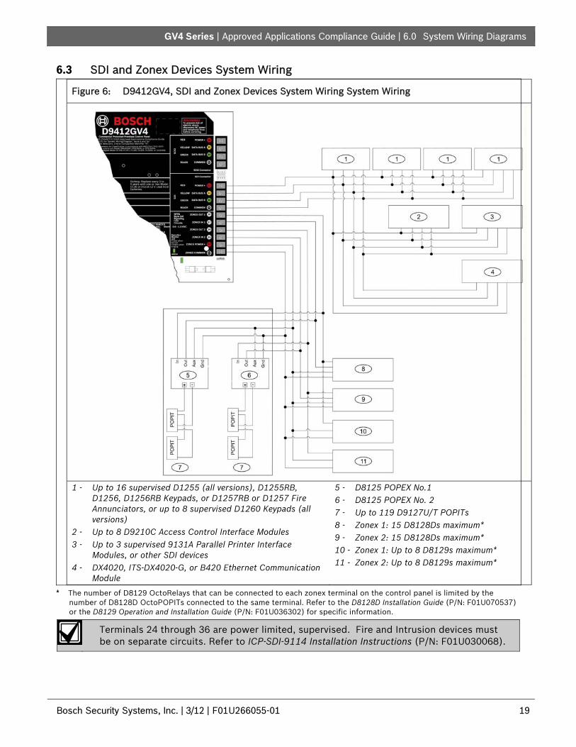
6.3 SDI and Zonex Devices System Wiring
Figure 6: D9412GV4, SDI and Zonex Devices System Wiring System Wiring
1 - Up to 16 supervised D1255 (all versions), D1255RB, D1256, D1256RB Keypads, or D1257RB or D1257 Fire Annunciators, or up to 8 supervised D1260 Keypads (all versions)
2 - Up to 8 D9210C Access Control Interface Modules 3 - Up to 3 supervised 9131A Parallel Printer Interface
Modules, or other SDI devices 4 - DX4020, ITS-DX4020-G, or B420 Ethernet Communication
Module
5 - D8125 POPEX No.1 6 - D8125 POPEX No. 2 7 - Up to 119 D9127U/T POPITs 8 - Zonex 1: 15 D8128Ds maximum* 9 - Zonex 2: 15 D8128Ds maximum* 10 - Zonex 1: Up to 8 D8129s maximum* 11 - Zonex 2: Up to 8 D8129s maximum*
* The number of D8129 OctoRelays that can be connected to each zonex terminal on the control panel is limited by the number of D8128D OctoPOPITs connected to the same terminal. Refer to the D8128D Installation Guide (P/N: F01U070537) or the D8129 Operation and Installation Guide (P/N: F01U036302) for specific information.
Terminals 24 through 36 are power limited, supervised. Fire and Intrusion devices must be on separate circuits. Refer to ICP-SDI-9114 Installation Instructions (P/N: F01U030068).

| Approved Applications Compliance Guide | 6.0 System Wiring Diagrams
20 Bosch Security Systems, Inc. | 3/12 | F01U266055-01
Figure 7: D7412GV4/D7212GV4 SDI and Zonex Devices System Wiring
1 - Up to 16 supervised D1255 (all versions), D1255RB, D1256, D1256RB Keypads, or D1257RB or D1257 Fire Annunciators, or up to 8 supervised D1260 Keypads (all versions)
2 - Up to 2 D9210C Access Control Interface Modules (not available on the D7212GV4)
3 - Up to 1 supervised 9131A Parallel Printer Interface Module, or other SDI device
4 - DX4020, ITS-DX4020-G, or B420 Ethernet Communication Module
5 - D8125 POPEX No. 1 6 - Up to 67 D9127U/T POPITs for D7412GV4, up to 32 D9127U/T POPITs for D7212GV4 7 - Zonex 1: Up to 9 D8128Ds for D7412GV4, up to 4 D8128Ds for D7212GV4* 8 - Zonex 1: Up to 8 D8129s maximum up to 3 D8128Ds for D7212GV4**
* The number of D8129 OctoRelays that can be connected to each zonex terminal on the control panel is limited by the number of D8128D OctoPOPITs connected to the same terminal. Refer to the D8128D Installation Guide (P/N: F01U070537) or the D8129 Operation and Installation Guide (P/N: F01U036302) for specific information.
Terminals 24 through 36 are power limited, supervised.
Fire and Intrusion devices must be on separate circuits. Refer to ICP-SDI-9114 Installation Instructions (P/N: F01U030068).
.

| Approved Applications Compliance Guide | 6.0 System Wiring Diagrams
.
Bosch Security Systems, Inc. | 3/12 | F01U266055-01 21
6.4 SDI2 Devices System Wiring
Figure 8: D9412GV4/D7412GV4/D7212GV4 SDI2 Devices System Wiring
1 - Up to 24 B208 Octo-input Modules 2 - Up to 12 B308 Octo-output Modules
3 - Up to 2 B420 Ethernet Communication Modules 4 - Up to 1 B820 Inovonics Interface Module
Table 4: SDI2 Modules Capacities Per Control Panel
Module D9412GV4 D7412GV4 D7212GV4
B208 Octo-input Modules 24 71 31
B308 Octo-output Modules 12 61 22
B420 Ethernet Communication Module 23 23 23
B820 Inovonics Interface Module 1 1 1 1 For the D7412GV4, only 5 inputs are available on the Octo-input at address 7 and for the D7212GV4, only 2 inputs are available on the Octo-input at address 3. 2 For the D7412GV4, only 4 relays are available on the Octo-output at address 6 and for the D7212GV4 only 4 relays are available on the Octo-output at address 2. 3 The maximum number of communication devices to be used on the control panel (both SDI and SDI2 buses) is 3. Of the two devices that can be used on the SDI2 bus both can be used for reporting / RPS communications or one can be used for reporting / RPS communications and the other can be used for automation.
Terminals 33 through 36 are power limited, supervised.
Fire and Intrusion devices must be on separate circuits. Refer to ICP-SDI-9114 Installation Instructions (P/N: F01U030068).

| Approved Applications Compliance Guide | 7.0 Current Ratings Charts
22 Bosch Security Systems, Inc. | 3/12 | F01U266055-01
7.0 Current Ratings Charts 7.1 D8125MUX Complete the chart in Table 5 to determine the maximum currents for the D8125MUX and its accessories. Transfer the total figures to Table 7 on page 24.
The maximum current draw for each MUX Bus is 75 mA.
Table 5: Current Rating Chart for D8125MUX
AC Power Off Maximum Current (mA)
In Alarm Maximum Current (mA)
Accessory Module
Qty Used Each Unit Qty Total System Each Unit Qty Total System
DS7432 ________ 10 x Qty = _________ 10 x Qty = _________
DS7457i ________ 0.35 x Qty = _________ 0.35 x Qty = _________
DS7460i ________ 1 x Qty = _________ 1 x Qty = _________
DS7465i ________ 1 x Qty = _________ 1 x Qty = _________
Ratings of other devices on the MUX Buses that are not shown above*:
_______________ _________ ________ x Qty = _________ _________ x Qty = _________
_______________ _________ ________ x Qty = _________ _________ x Qty = _________
_______________ _________ ________ x Qty = _________ _________ x Qty = _________
_______________ _________ ________ x Qty = _________ _________ x Qty = _________
_______________ _________ ________ x Qty = _________ _________ x Qty = _________
_______________ _________ ________ x Qty = _________ _________ x Qty = _________
_______________ _________ ________ x Qty = _________ _________ x Qty = _________
_______________ _________ ________ x Qty = _________ _________ x Qty = _________
_______________ _________ ________ x Qty = _________ _________ x Qty = _________
_______________ _________ ________ x Qty = _________ _________ x Qty = _________
_______________ _________ ________ x Qty = _________ _________ x Qty = _________
_______________ _________ ________ x Qty = _________ _________ x Qty = _________
_______________ _________ ________ x Qty = _________ _________ x Qty = _________
_______________ _________ ________ x Qty = _________ _________ x Qty = _________
Column A Total = _________ Column B Total = _________
* Refer to the device’s installation guide for current draw values.

7.0 Current Ratings Charts
.
Bosch Security Systems, Inc. | 3/12 | F01U266055-01 23
7.2 Standby Battery Calculations UL 365 requires 72 h of standby battery capacity. Limit the auxiliary power current for all devices, including keypads, to 300 mA or less to meet this requirement.
Table 6: Standby Battery Requirements
Type Required Capacity Calculations
Household Burglary and Commercial Burglary
4 h
Bank Safe and Vault 72 h (UL 365). Auxiliary power current for all devices, including keypads, must be limited to 300 mA or less to meet this requirement.
Central Station or Local Fire Alarm 24 h + 5 min of alarm operation. Remote Station or Auxiliary Fire Alarm
60 h + 5 min of alarm operation.
Household Fire Warning Equipment
24 h + 4 min of alarm operation.

| Approved Applications Compliance Guide | 7.0 Current Ratings Charts
24 Bosch Security Systems, Inc. | 3/12 | F01U266055-01
Table 7: Current Rating Chart for Standby Battery Calculations
A B C
AC Power On
Normal Current (mA) AC Power Off
Minimum Current (mA) In Alarm
Maximum Current (mA)
Model Number Qty Used Each Unit
Qty Total Each Unit Qty Total Each Unit Qty Total
D9412GV4/ D7412GV4
D7212GV4 ______ 225 x 1 = 225 225 x 1 = 225 300 x 1 = 300
B208 ______ 35 x Qty = ______ 35 x Qty = ______ 35 x Qty = ______ B3084 ______ 22 x Qty = ______ 22 x Qty = ______ 22 x Qty = ______ B4205 ______ 90 x Qty = ______ 90 x Qty = ______ 90 x Qty = ______ B820 ______ 100 x Qty = ______ 100 x Qty = ______ 110 x Qty = ______ D125B ______ 25 x Qty = ______ 25 x Qty = ______ 168 x Qty = ______ D127 ______ 5 x Qty = ______ 5 x Qty = ______ 55 x Qty = ______ D129 ______ 23 x Qty = ______ 23 x Qty = ______ 25 x Qty = ______ D185 ______ 245 x Qty = ______ 245 x Qty = ______ 300 x Qty = ______ D192G ______ 35 x Qty = ______ 35 x Qty = ______ 100 x Qty = ______ D1255/D1255B ______ 104 x Qty = ______ 106 x Qty = ______ 206 x Qty = ______ D1256/D1257 ______ 104 x Qty = ______ 106 x Qty = ______ 206 x Qty = ______ D1255RB ______ 104 x Qty = ______ 106 x Qty = ______ 225 x Qty = ______ D1256RB ______ 104 x Qty = ______ 106 x Qty = ______ 225 x Qty = ______ D1257RB ______ 104 x Qty = ______ 106 x Qty = ______ 225 x Qty = ______ D1260/D1260B ______ 140 x Qty = ______ 140 x Qty = ______ 250 x Qty = ______ D720 ______ 20 x Qty = ______ 20 x Qty = ______ 100 x Qty = ______ D8125 ______ 60 x Qty = ______ 60 x Qty = ______ 60 x Qty = ______
D8125MUX ______ 140 x Qty = ______ 140 X Qty = ______ 140 X Qty
= ______
D8128D ______ 25 x Qty = ______ 25 x Qty = ______ 50 x Qty = ______ D8129 ______ 20 x Qty = ______ 20 x Qty = ______ Refer to footnote1 = ______
D8130 ______ 7 x Qty = ______ 7 x Qty = ______ 60 x Qty = ______ D9127T/U ______ 0.8 x Qty = ______ 0.8 x Qty = ______ 0.8 x Qty = ______ D9131A ______ 21 x Qty = ______ 21 x Qty = ______ 23 x Qty = ______ D9210C ______ 110 x Qty = ______ 110 x Qty = ______ 1102 x Qty = ______ D928 ______ 20 x Qty = ______ 20 x Qty = ______ 100 x Qty = ______ DX4010V23 ______ 50 x Qty = ______ 50 x Qty = ______ 55 x Qty = ______ DX4020 ______ 80 x Qty = ______ 80 x Qty = ______ 84 x Qty = ______ ITS-DX4020-G ______ 50 x Qty = ______ 50 x Qty = ______ 200 x Qty = ______ Ratings of other devices in the system that are not shown above:
____ ______ _____ x Qty = ______ ______ x Qty = ______ ____ x Qty = ______ ____ ______ _____ x Qty = ______ ______ x Qty = ______ ____ x Qty = ______ ____ ______ _____ x Qty = ______ ______ x Qty = ______ ____ x Qty = ______ ____ ______ _____ x Qty = ______ ______ x Qty = ______ ____ x Qty = ______ Total A = ______ Total B = ______ Total C = ______
1 The In Alarm calculation for the D8129 is: 20 x Qty + (16.25 x number of relays) 2 Use 110 mA + reader current. Do not exceed 260 mA. 3 UL requires that the DX4010V2 be used for programming only. 4 (digital section = 22mA) + (Qty of relays x 16 mA)= total current. (Add 16 mA for each relay being used) 5 10BaseT Ethernet: 90mA max, 100BaseT Ethernet: 100mA max
| Approved Applications Compliance Guide | 7.0 Current Ratings Charts
.
Bosch Security Systems, Inc. | 3/12 | F01U266055-01 25
Because of changing regulations, verify the necessary time with your local authority having jurisdiction (AHJ).
Refer to Table 7 on page 24 for totals B and C used in the formulas below. When connecting two batteries, use either the D122/D122L Dual Battery Wiring Harness or the D8132 Battery Charger Module.

| Approved Applications Compliance Guide | 8.0 NFPA 72 Fire Alarm Applications
26 Bosch Security Systems, Inc. | 3/12 | F01U266055-01
8.0 NFPA 72 Fire Alarm Applications 8.1 Household Burglary and Commercial Burglary Four hours of standby battery capacity are required.
8.2 Bank Safe and Vault
Because of changing regulations, verify the necessary time with your local authority having jurisdiction (AHJ).
UL 365 requires 72 h of standby battery capacity. Limit the auxiliary power current for all devices, including keypads, to 300 mA or less to meet this requirement.
Table 8: Standby Battery Requirements
Type Required Capacity Calculations
Household Burglary and Commercial Burglary
4 h
Bank Safe and Vault 72 h (UL 365). Auxiliary power current for all devices, including keypads, must be limited to 300 mA or less to meet this requirement.
Central Station or Local Fire Alarm 24 h + 5 min of alarm operation. Refer to Table 10 on page 27.
Remote Station or Auxiliary Fire Alarm
60 h + 5 min of alarm operation. Refer to Table 11 on page 27.
Household Fire Warning Equipment
24 h + 4 min of alarm operation. Refer to Table 12 on page 28.
8.3 Standby Battery Calculation
Because of changing regulations, verify the necessary time with your local authority having jurisdiction (AHJ).
Refer to Table 7 on page 24 for totals B and C used in the formulas below. When connecting two batteries, use either the D122 Dual Battery Wiring Harness or the D8132 Battery Charger Module.
Table 9: General Ampere-Hour (Ah) Calculation Formula
Total B1 Hours Total C1 Alarm Operation2 Contingency Total Ah3 (________ x 24 ) + ( ________ x 0.083) + 10% = _________
1 Refer to Table 7 on page 24.
2 Value = Minutes of alarm operation 60
3 Total Ah requirements must not exceed the Ah capacity of batteries: One D126 Battery = 7 Ah Two D126 Batteries = 14 Ah One D1218 Battery = 17.2 or 18 Ah Two D1218 Batteries = 34.4 or 36 Ah

| Approved Applications Compliance Guide | 8.0 NFPA 72 Fire Alarm Applications
.
Bosch Security Systems, Inc. | 3/12 | F01U266055-01 27
8.4 Central Station or Local Systems Central Station or Local Systems require 24 h of standby plus 5 min of alarm operation at the end of the 24-hour period. A single battery is sometimes adequate for central station systems, but two batteries must be installed to meet the basic standby requirements for a local system installation. Use the battery ampere-hour (Ah) calculations to confirm compliance. The formula in Table 10 includes the calculation for 5 min of alarm operation at the end of the 24-hour period, as well as a 10% contingency factor that allows for depletion of battery capacity with age.
Because of changing regulations, verify the necessary time with your local AHJ (authority having jurisdiction).
Table 10: Central Stations or Local Systems Ah Calculation Formula
Total B1 Hours Total C1 Alarm Operation2 Contingency Total Ah3 ( ________ x 24) + ( ________ x 0.083) + 10% = _________
1 Refer to Table 7 on page 24.
2 Value = Minutes of alarm operation 60
3 Total Ah requirements must not exceed the Ah capacity of batteries: One D126 Battery = 7 Ah Two D126 Batteries = 14 Ah One D1218 Battery = 17.2 or 18 Ah Two D1218 Batteries = 34.4 or 36 Ah
8.5 Remote Station or Auxiliary Systems Remote Station or Auxiliary Systems require 60 h of standby plus 5 min of alarm operation at the end of the 60-hour period. A D8132 Battery Charger Module with additional batteries installed in a separate D8109 or D8108A Enclosure might be required in the system to meet the basic standby requirements for a remote station or auxiliary system installation. Use battery Ah calculations to confirm compliance. The formula in Table 11 includes the calculation for 5 min of alarm operation at the end of the 60-hr period, as well as a 10% contingency factor that allows for depletion of battery capacity with age.
Because of changing regulations, verify the necessary time with your local AHJ (authority having jurisdiction).
Table 11: Remote Station or Auxiliary Systems Ah Calculation Formula
Total B1 Hours Total C1 Alarm Operation2 Contingency Total Ah3 ( ________ x 60) + ( ________ x 0.083) + 10% = _________
1 Refer to Table 7 on page 24.
2 Value = Minutes of alarm operation 60
3 Total Ah requirements must not exceed the Ah capacity of batteries: One D126 Battery = 7 Ah Two D126 Batteries = 14 Ah One D1218 Battery = 17.2 or 18 Ah Two D1218 Batteries = 34.4 or 36 Ah

| Approved Applications Compliance Guide | 8.0 NFPA 72 Fire Alarm Applications
28 Bosch Security Systems, Inc. | 3/12 | F01U266055-01
8.6 Household Fire Warning Equipment The Household Fire Warning Equipment Standard requires 24 h of standby current plus 4 min of alarm operation at the end of the 24-hour period. Use battery Ah calculations to confirm compliance. The formula in Table 12 includes the calculation for 4 min of alarm operation at the end of the 24-hour period, and a 10% contingency factor that allows for depletion of battery capacity with age.
Because of changing regulations, verify the necessary time with your local AHJ (authority having jurisdiction).
Table 12: Household Fire Ah Calculation Formula
Total B1 Hours Total C1 Alarm Operation2 Contingency Total Ah3 (_______ x 24) + ( ________ x 0.067) + 10% = _________
1 Refer to Table 7 on page 24.
2 Value = Minutes of alarm operation 60
3 Total Ah requirements must not exceed the Ah capacity of batteries: One D126 Battery = 7 Ah Two D126 Batteries = 14 Ah One D1218 Battery = 17.2 or 18 Ah Two D1218 Batteries = 34.4 or 36 Ah
8.7 UL 609 (D9412GV4/D7412GV4/D7212GV4) The leads providing operating power to the alarm sounding device shall be electrically and mechanically protected as required in the Standard for Installation and Classification of Mercantile and Bank Burglar-Alarm Systems, UL 681, or the circuit shall be constructed so that the system is not defeated by cutting or short-circuiting connections between the control unit and the alarm housing.
The alarm housing for a bank alarm system without a remote alarm transmission connection shall be mounted on the outside of the building, visible from a public street or highway. It shall be accessible for examination and repair. It shall also be located not more than four stories above the street level unless:
A second alarm sounding device and housing, intended for outside service [see 3.3(a)], is mounted adjacent to the premises or area of the building in which the alarm system is installed or
A second alarm sounding device, intended for inside service [see 3.3(b)], is mounted within the premises.
In either case, the outside alarm sounding device and housing may be mounted as high as the seventh floor.
8.8 UL 365 (D9412GV4/D7412GV4/D7212GV4) In a mercantile burglar alarm system, a mercantile alarm sounding device located within a building but outside the protected area, is acceptable, provided it is rated for outside service and alarm conditions are transmitted to:
a. The dispatch location of the law enforcement agency having jurisdiction over the protected property or
b. A central station or residential monitoring station complying with the Standard for Central-Station Alarm Services, UL 827.

Bosch Security Systems, Inc. | 3/12 | F01U266055-01 29
In a mercantile burglar alarm system, an alarm sounding device located within the area of greatest protection, or outside the area of greatest protection but within an area protected by an alarm system and that shares a common control unit with the system installed in the area of greatest protection, is acceptable provided it is rated for inside service and alarm conditions are transmitted to:
a. The dispatch location of the law enforcement agency having jurisdiction over the protected property or
b. A central station or residential monitoring station complying with the Standard for Central-Station Alarm Services, UL 827.
An inside sounding device shall be mounted at least 10 feet (3.05 m) above the floor or at the surface of the ceiling. When there is a fixed construction within the area that could provide access for an intruder, the alarm sounding device shall also be mounted at least 4 ft (1.2. m) as measured horizontally, away from the edges of the fixed construction or at least 10 ft (3.05 m) above it so as to minimize access by an intruder.
8.9 UL 636 (D9412GV4/D7412GV4/D7212GV4) To comply with UL 636, UL Standard for Holdup Alarm Units and Systems, the GV4 Series control panels must be installed with the Bosch Model B820 Inovonics Interface Module, Inovonics EchoStream Model EN4200 Serial Receiver and any of the following Inovonics EchoStream transmitters: EN1235SF, EN1235DF, or EN1249.

Bosch Security Systems, Inc. 130 Perinton Parkway Fairport, NY 14450 USA
www.boschsecurity.com © Bosch Security Systems, Inc., 2012