f01.justanswer.com · Web viewDisconnect the negative battery cable. Remove the transaxle from the...
25
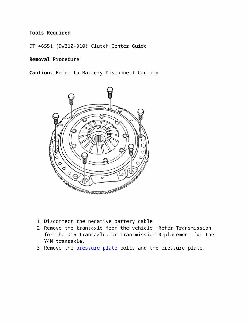
Tools Required DT 46551 (DW210-010) Clutch Center Guide Removal Procedure Caution: Refer to Battery Disconnect Caution 1. Disconnect the negative battery cable. 2. Remove the transaxle from the vehicle. Refer Transmission for the D16 transaxle, or Transmission Replacement for the Y4M transaxle. 3. Remove the pressure plate bolts and the pressure plate.
Transcript of f01.justanswer.com · Web viewDisconnect the negative battery cable. Remove the transaxle from the...
Tools Required
DT 46551 (DW210-010) Clutch Center Guide
Removal Procedure
Caution: Refer to Battery Disconnect Caution
1. Disconnect the negative battery cable. 2. Remove the transaxle from the vehicle. Refer Transmission for the D16 transaxle, or
Transmission Replacement for the Y4M transaxle. 3. Remove the pressure plate bolts and the pressure plate.
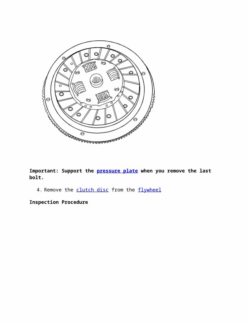
Important: Support the pressure plate when you remove the last bolt.
4. Remove the clutch disc from the flywheel
Inspection Procedure
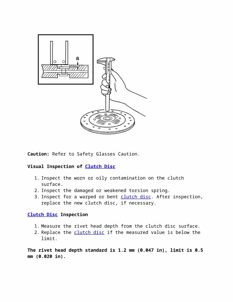
Caution: Refer to Safety Glasses Caution.
Visual Inspection of Clutch Disc
1. Inspect the worn or oily contamination on the clutch surface. 2. Inspect the damaged or weakened torsion spring. 3. Inspect for a warped or bent clutch disc. After inspection, replace the new clutch disc, if
necessary.
Clutch Disc Inspection
1. Measure the rivet head depth from the clutch disc surface. 2. Replace the clutch disc if the measured value is below the limit.
The rivet head depth standard is 1.2 mm (0.047 in), limit is 0.5 mm (0.020 in).
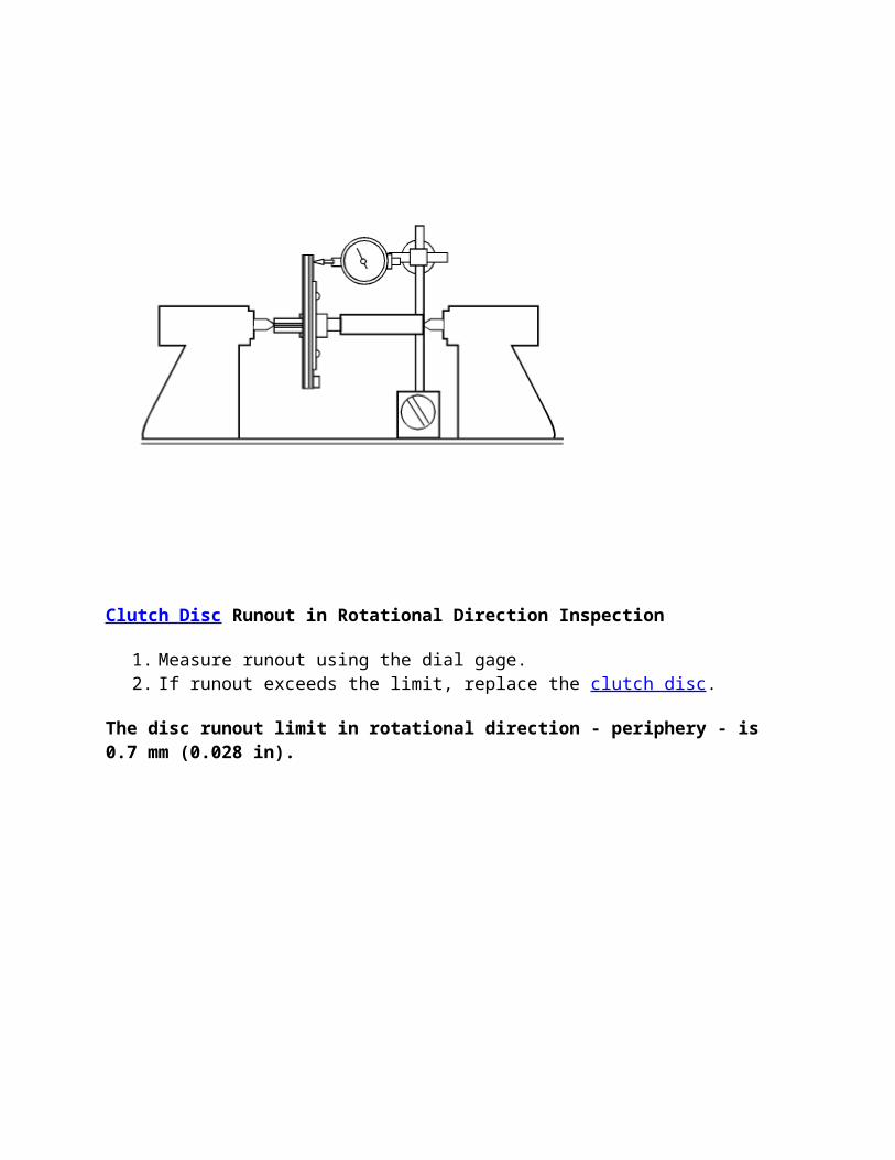
Clutch Disc Runout in Rotational Direction Inspection
1. Measure runout using the dial gage. 2. If runout exceeds the limit, replace the clutch disc.
The disc runout limit in rotational direction - periphery - is 0.7 mm (0.028 in).
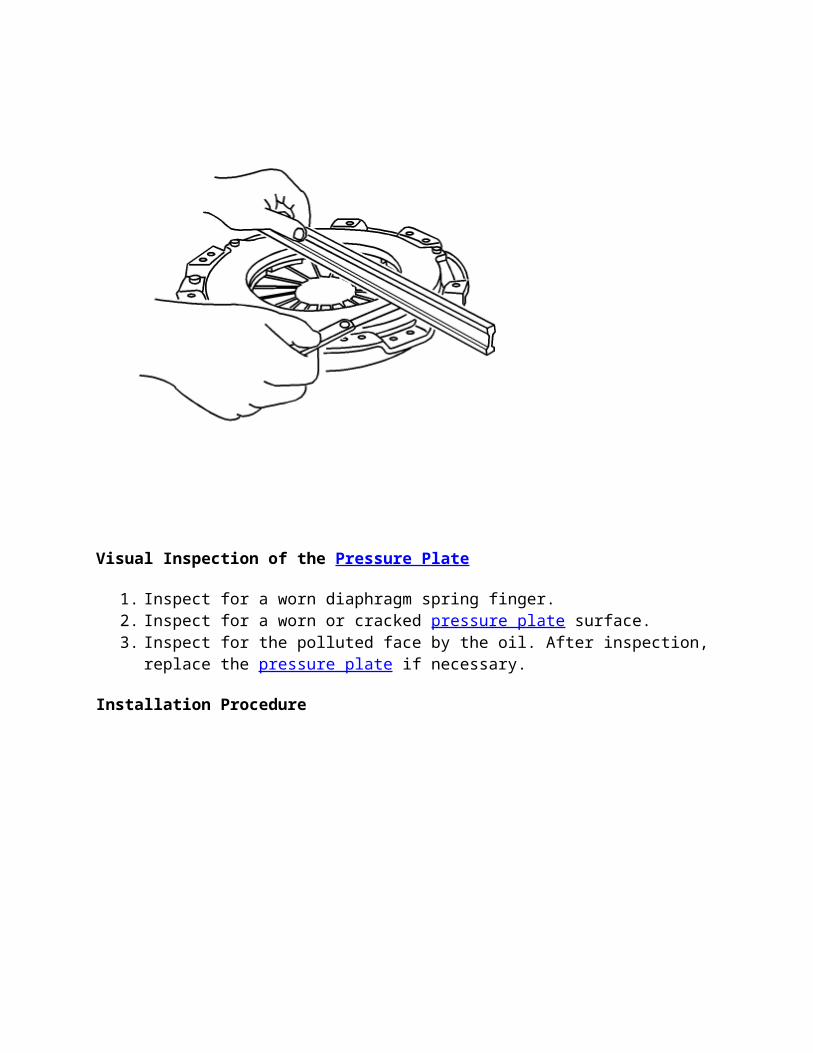
Visual Inspection of the Pressure Plate
1. Inspect for a worn diaphragm spring finger. 2. Inspect for a worn or cracked pressure plate surface. 3. Inspect for the polluted face by the oil. After inspection, replace the pressure plate if
necessary.
Installation Procedure
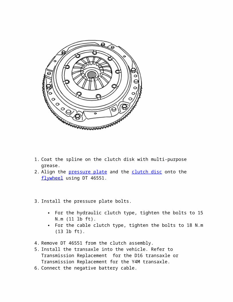
1. Coat the spline on the clutch disk with multi-purpose grease. 2. Align the pressure plate and the clutch disc onto the flywheel using DT 46551.
3. Install the pressure plate bolts.
For the hydraulic clutch type, tighten the bolts to 15 N.m (11 lb ft). For the cable clutch type, tighten the bolts to 18 N.m (13 lb ft).
4. Remove DT 46551 from the clutch assembly. 5. Install the transaxle into the vehicle. Refer to Transmission Replacement for the D16
transaxle or Transmission Replacement for the Y4M transaxle. 6. Connect the negative battery cable.
Clutch Master Cylinder Replacement
Removal Procedure
Before disconnecting the reservoir tank hose, remove the clutch/brake fluid from the reservoir tank.
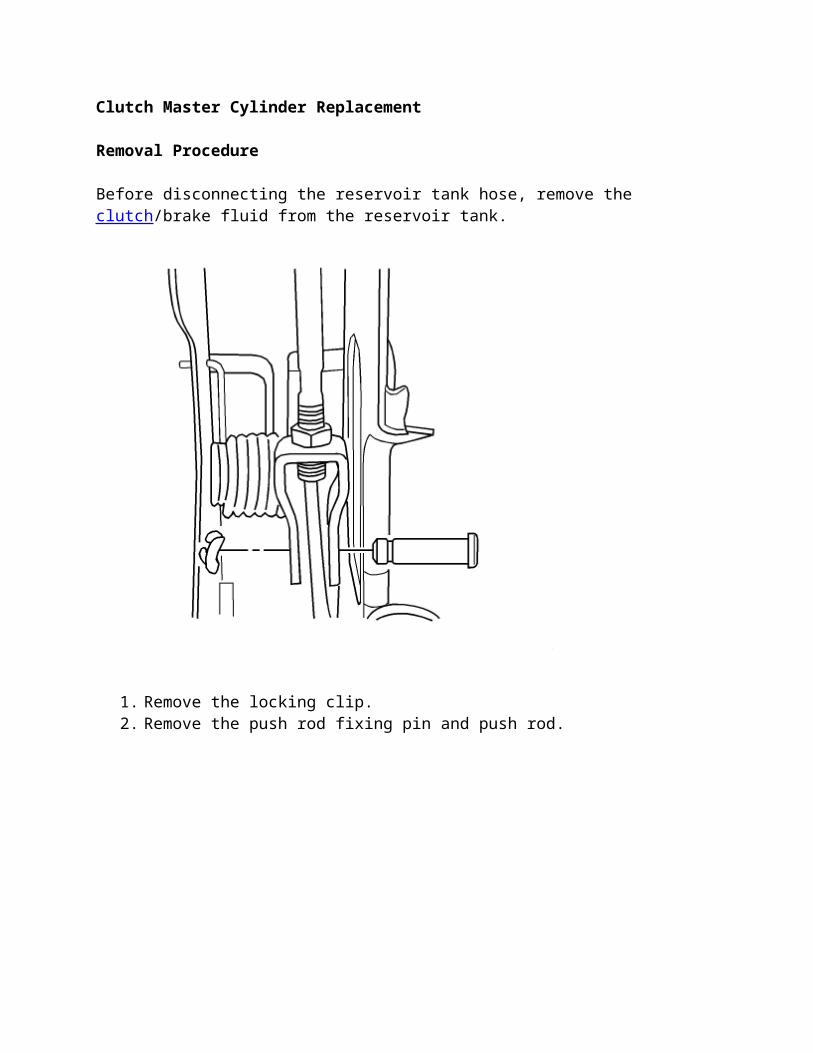
1. Remove the locking clip. 2. Remove the push rod fixing pin and push rod.
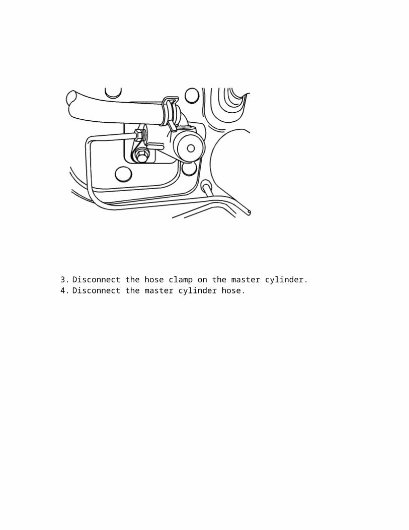
3. Disconnect the hose clamp on the master cylinder. 4. Disconnect the master cylinder hose.

5. Remove the master cylinder pipe.
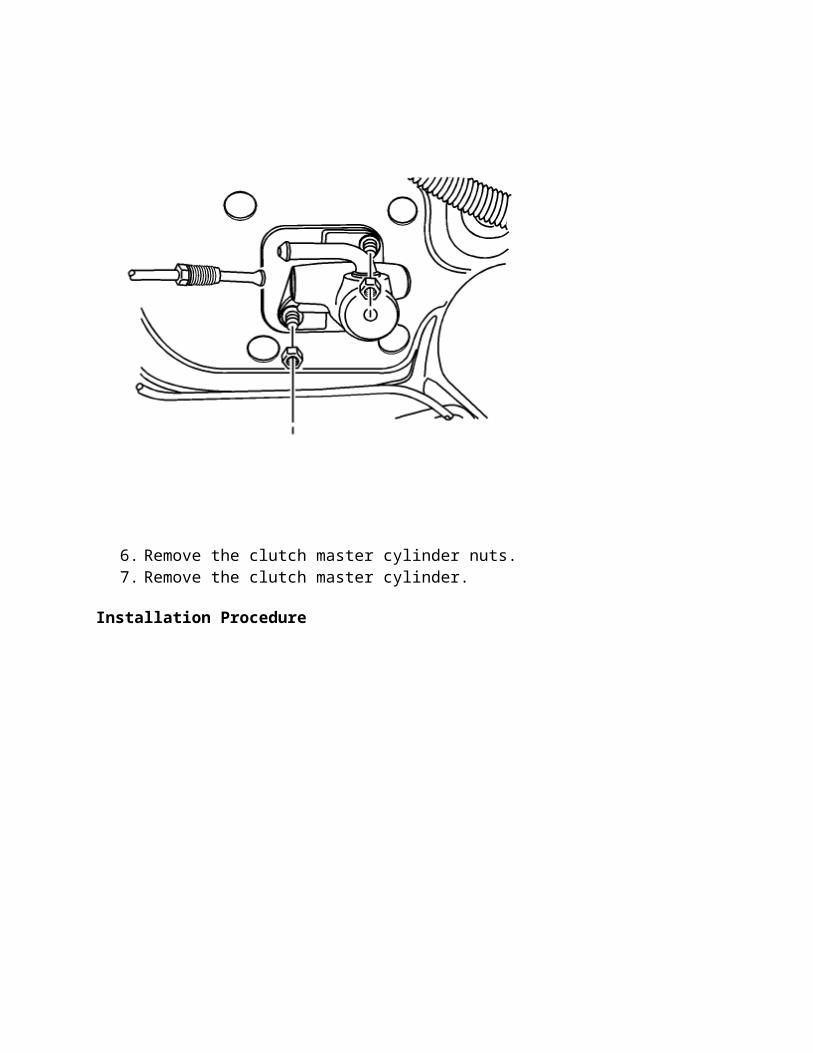
6. Remove the clutch master cylinder nuts. 7. Remove the clutch master cylinder.
Installation Procedure
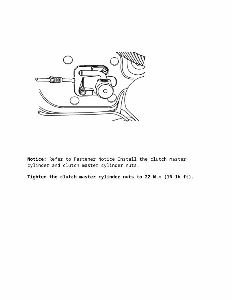
Notice: Refer to Fastener Notice Install the clutch master cylinder and clutch master cylinder nuts.
Tighten the clutch master cylinder nuts to 22 N.m (16 lb ft).
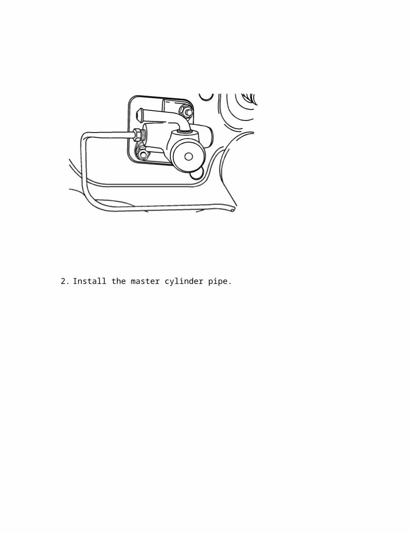
2. Install the master cylinder pipe.

3. Connect the master cylinder hose. 4. Connect the hose clamp on the master cylinder.
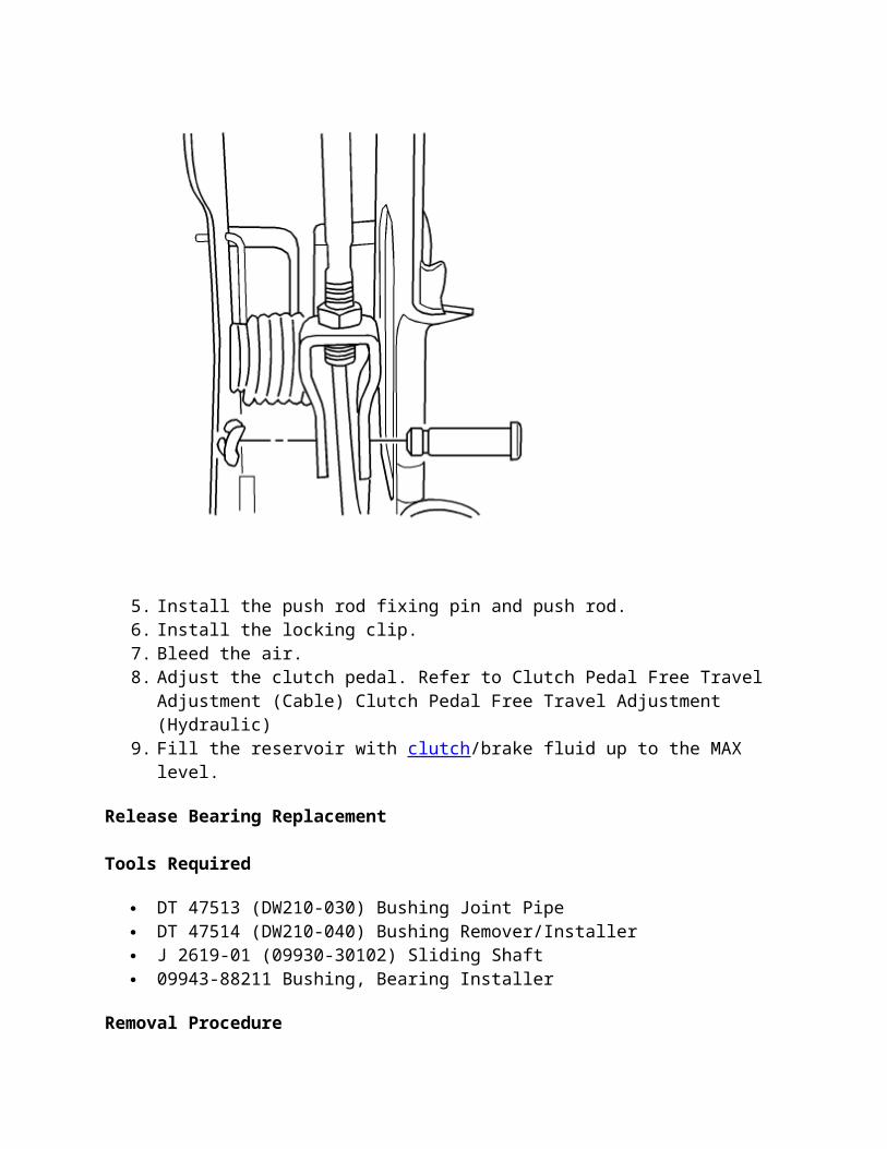
5. Install the push rod fixing pin and push rod. 6. Install the locking clip. 7. Bleed the air. 8. Adjust the clutch pedal. Refer to Clutch Pedal Free Travel Adjustment (Cable) Clutch
Pedal Free Travel Adjustment (Hydraulic) 9. Fill the reservoir with clutch/brake fluid up to the MAX level.
Release Bearing Replacement
Tools Required
DT 47513 (DW210-030) Bushing Joint Pipe DT 47514 (DW210-040) Bushing Remover/Installer J 2619-01 (09930-30102) Sliding Shaft 09943-88211 Bushing, Bearing Installer
Removal Procedure
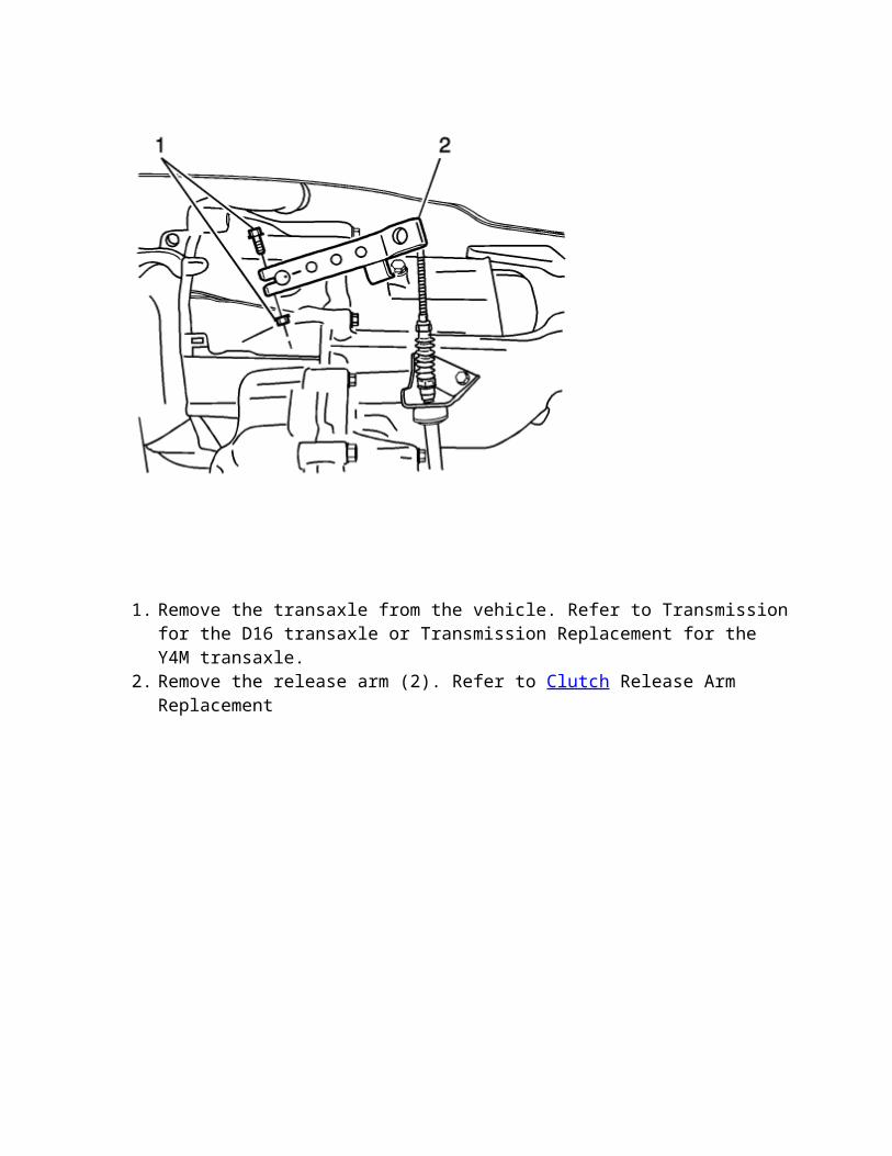
1. Remove the transaxle from the vehicle. Refer to Transmission for the D16 transaxle or Transmission Replacement for the Y4M transaxle.
2. Remove the release arm (2). Refer to Clutch Release Arm Replacement
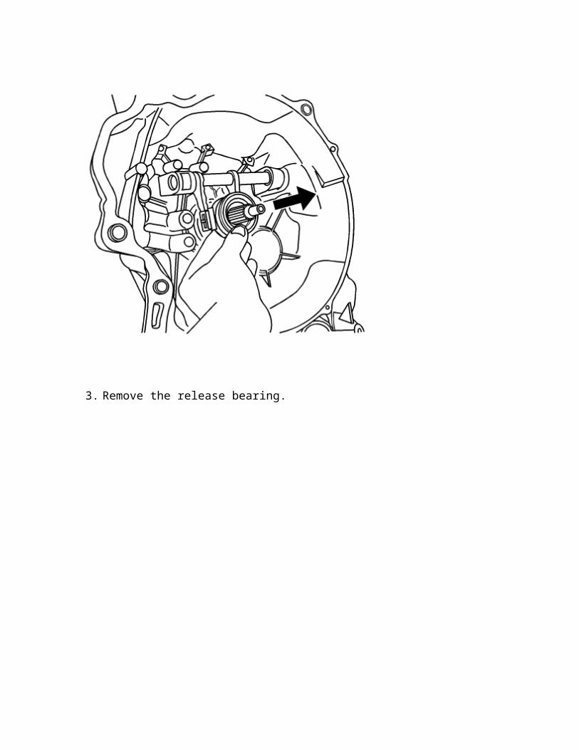
3. Remove the release bearing.
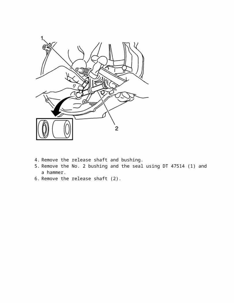
4. Remove the release shaft and bushing. 5. Remove the No. 2 bushing and the seal using DT 47514 (1) and a hammer. 6. Remove the release shaft (2).
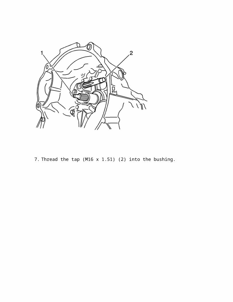
7. Thread the tap (M16 x 1.51) (2) into the bushing.
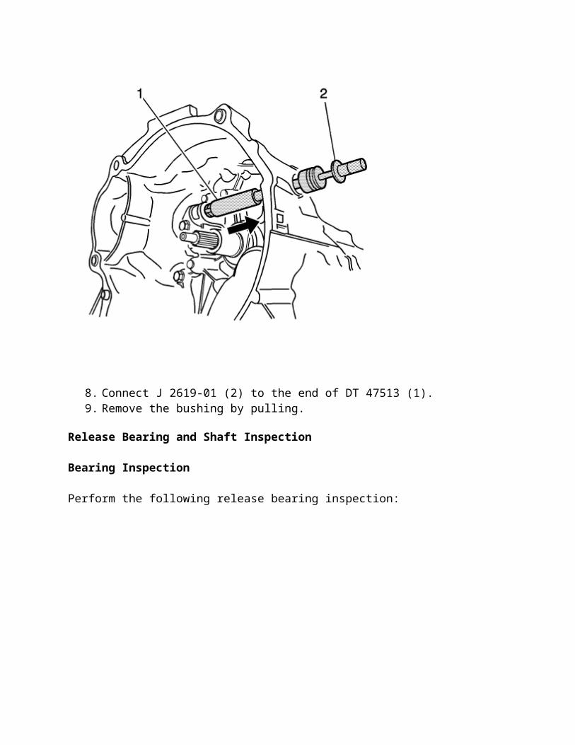
8. Connect J 2619-01 (2) to the end of DT 47513 (1). 9. Remove the bushing by pulling.
Release Bearing and Shaft Inspection
Bearing Inspection
Perform the following release bearing inspection:
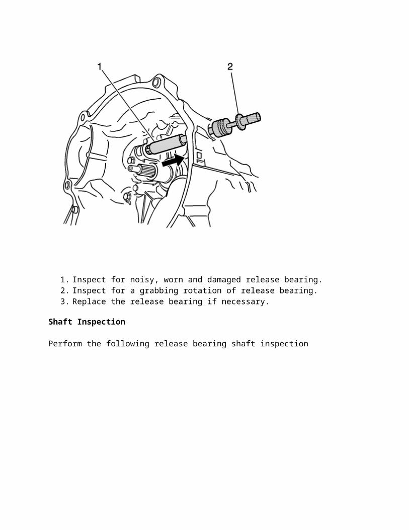
1. Inspect for noisy, worn and damaged release bearing. 2. Inspect for a grabbing rotation of release bearing. 3. Replace the release bearing if necessary.
Shaft Inspection
Perform the following release bearing shaft inspection
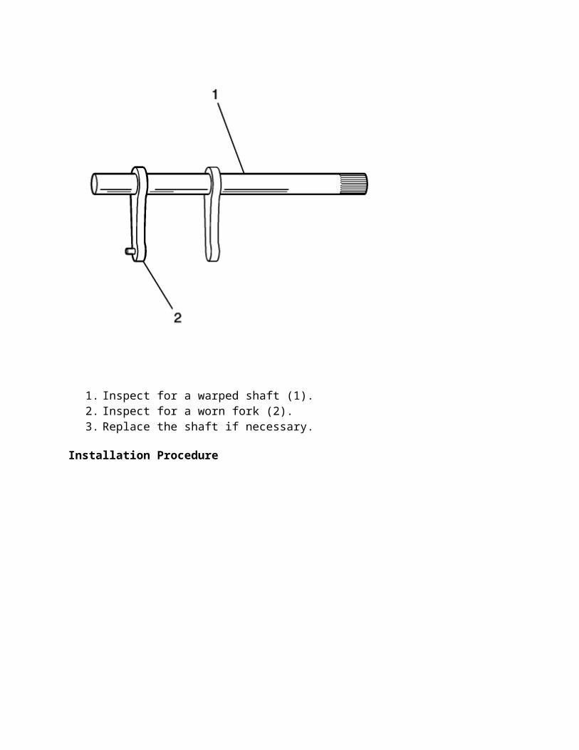
1. Inspect for a warped shaft (1). 2. Inspect for a worn fork (2). 3. Replace the shaft if necessary.
Installation Procedure
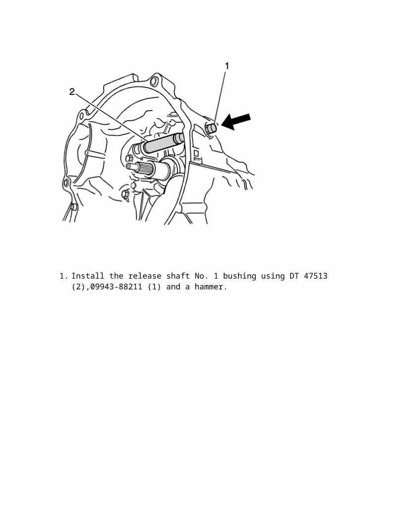
1. Install the release shaft No. 1 bushing using DT 47513 (2),09943-88211 (1) and a hammer.
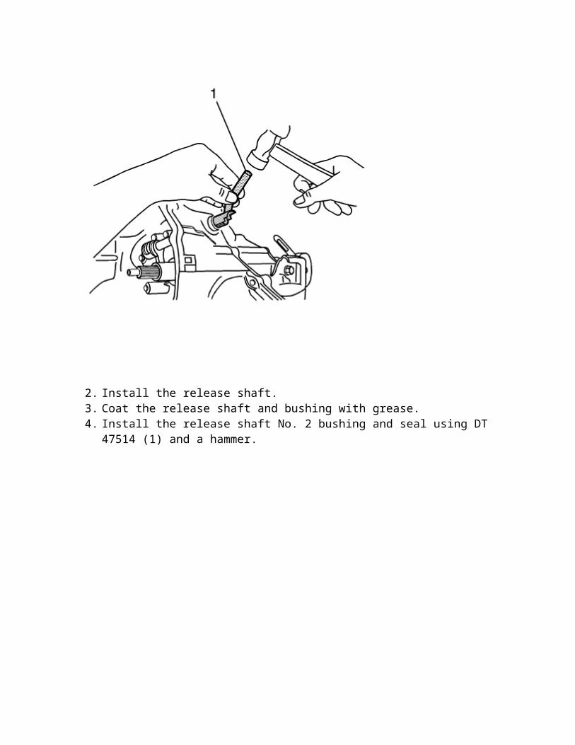
2. Install the release shaft. 3. Coat the release shaft and bushing with grease. 4. Install the release shaft No. 2 bushing and seal using DT 47514 (1) and a hammer.
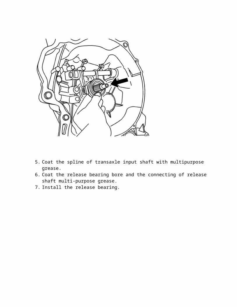
5. Coat the spline of transaxle input shaft with multipurpose grease. 6. Coat the release bearing bore and the connecting of release shaft multi-purpose grease. 7. Install the release bearing.
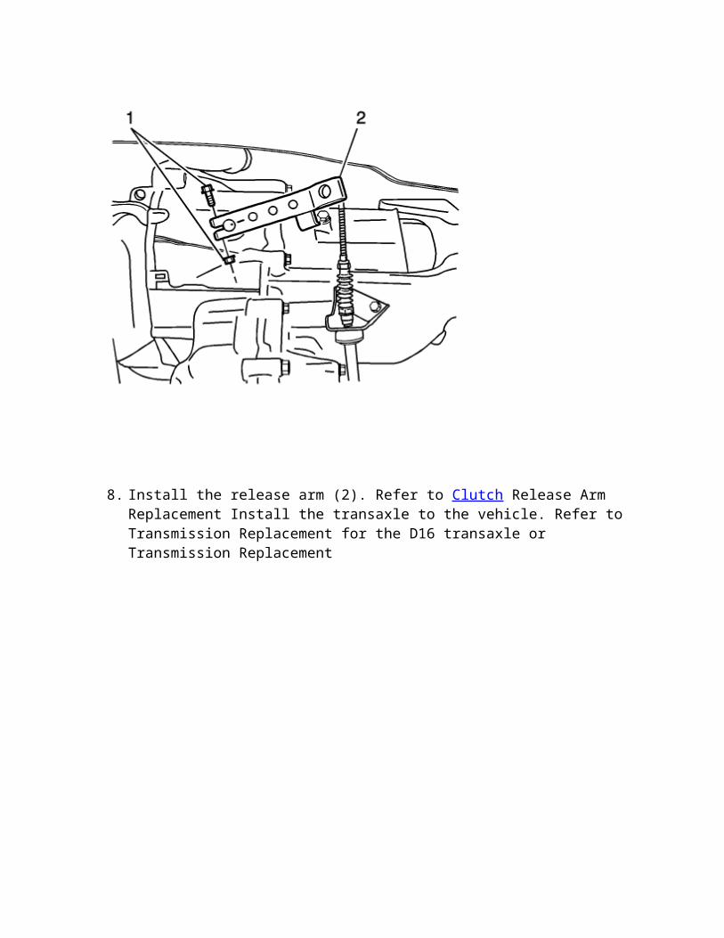
8. Install the release arm (2). Refer to Clutch Release Arm Replacement Install the transaxle to the vehicle. Refer to Transmission Replacement for the D16 transaxle or Transmission Replacement