F Series Indoor IP User's Manua Product/K... · Web viewAlarm Input Device (detector, sensor and so...
14
K Series Cube Network Camera Quick Start Guide V 1.0.1
Transcript of F Series Indoor IP User's Manua Product/K... · Web viewAlarm Input Device (detector, sensor and so...

K Series Cube Network Camera Quick Start Guide
V 1.0.1

1 Packing List
Device × 1 QSG ×1
Power Adapter ×1 Screw Package ×1
Installation Position Map ×1
1

2 Product Appearance
Figure 2-1 Figure 2-2
Figure 2-3
Please refer to the following sheet for more details about each port.
2

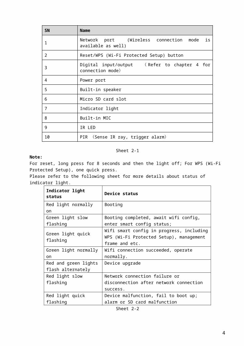
Sheet 2-1Note: For reset, long press for 8 seconds and then the light off; For WPS (Wi-Fi Protected Setup), one quick press.Please refer to the following sheet for more details about status of indicator light.
Indicator light status Device statusRed light normally on Booting
Green light slow flashing Booting completed, await wifi config, enter smart config status;
Green light quick flashingWifi smart config in progress, including WPS (Wi-Fi Protected Setup), management frame and etc.
Green light normally on Wifi connection succeeded, operate normally.
Red and green lights flash alternately
Device upgrade
Red light slow flashing Network connection failure or disconnection after network connection success.
Red light quick flashing Device malfunction, fail to boot up; alarm or SD card malfunction
Sheet 2-2
3
SN Name
1 Network port (Wireless connection mode is available as well)
2 Reset/WPS (Wi-Fi Protected Setup) button
3 Digital input/output (Refer to chapter 4 for connection mode)4 Power port
5 Built-in speaker
6 Micro SD card slot
7 Indicator light
8 Built-in MIC
9 IR LED
10 PIR (Sense IR ray, trigger alarm)
3 Operate by EasyViewerStep 1 Power on the camera. Step 2 Connect iphone to a WiFi signal. Step 3 Open EasyViewer (downloaded from APP Store), choose Device Manager.
Figure 3-1Step 4 Please select “Wired” when the network cable is connected, choose “WiFi Configuration” for wireless connection. Here is an example of wireless connection.
4

Figure 3-2Step 5Input a device name and scan the QR code on camera, then “next”.
Figure 3-3
5

Figure 3-4Step 6 Input the WiFi password, then “next”.
Figure 3-5 Step 7 Connection succeeds.
6

Figure 3-6 Figure 3-7 Figure 3-8Note: Please try again or check the WiFi password if it failed. The WiFi configuration will be closed if activating WPS (WI-FI Protected Setup) function; Please reset the device if you still need to configure WiFi via EasyViewer.
7

4 External Alarm Input/Output Device IPC supports external alarm device, it can externally connect to alarm input/output device via “Digital input/output”. 4.1.1 Alarm Input Device (detector, sensor and so on)Please refer to the following figure for alarm input information. See Figure 4-1.Alarm input: When the input signal is idle or grounded, the device can collect the different statuses of the alarm input port. When the input signal is connected to the 5V or is idle, the device collects the logic “1”. When the input signal is grounded, the device collects the logic “0”.
Figure 4-1 Alarm input
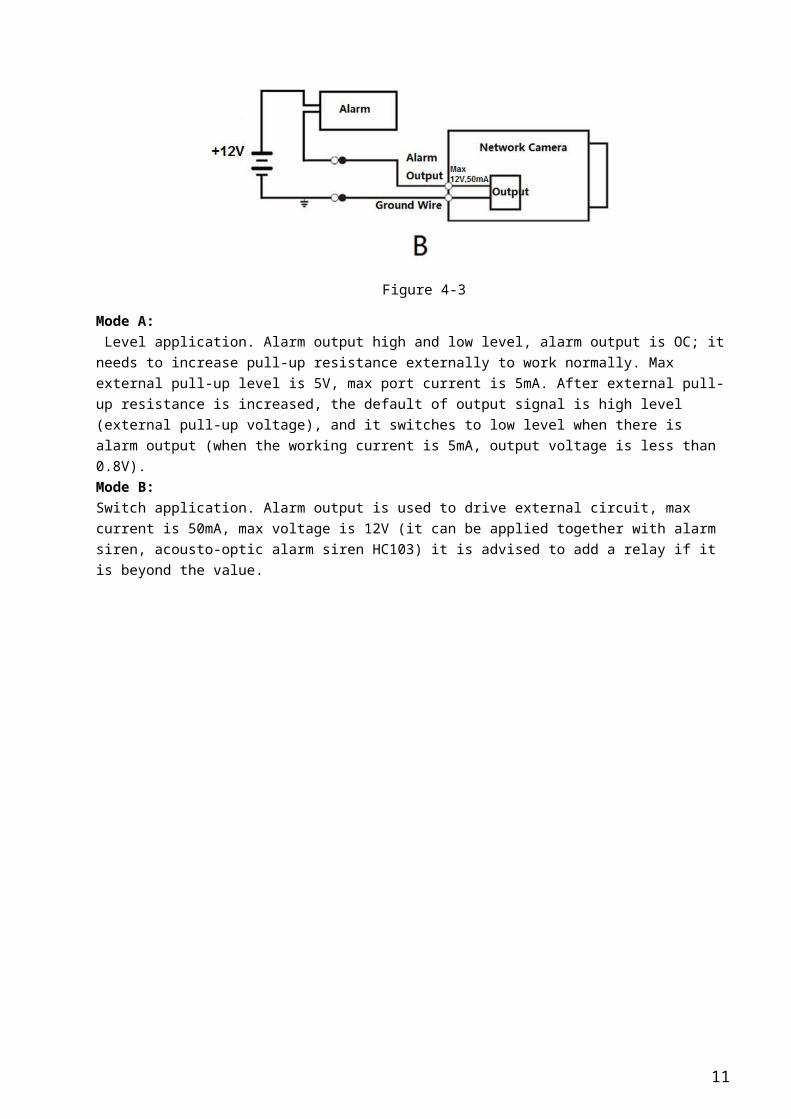
4.1.2 Alarm Output Device (alarm device, beeper and so on)Please refer to Figure 4-2 and 4-3 for alarm output information.
Figure 4-2
Figure 4-3
8

Mode A: Level application. Alarm output high and low level, alarm output is OC; it needs to increase pull-up resistance externally to work normally. Max external pull-up level is 5V, max port current is 5mA. After external pull-up resistance is increased, the default of output signal is high level (external pull-up voltage), and it switches to low level when there is alarm output (when the working current is 5mA, output voltage is less than 0.8V). Mode B:Switch application. Alarm output is used to drive external circuit, max current is 50mA, max voltage is 12V (it can be applied together with alarm siren, acousto-optic alarm siren HC103) it is advised to add a relay if it is beyond the value.
9

5 Device Installation ImportantPlease make sure the installation surface can min support the 3X weight of the camera and the bracket.
Figure 5-1
Step 1Paste the installation map on the installation surface such as wall, ceiling or the wood. Step 2 Dig holes in the installation surface according to the installation map.Step 3Insert the expansion bolts from the accessories bag to the holes you just dug. If it is the wood surface you can skip to the next step. Step 4Fix the device with screw in the accessories bag.Step 5Connect the cable and then boot up the device. Step 6Loosen the adjust knob for a little bit, adjust the camera to proper surveillance position according to your practical requirements.Step 7Secure the knob of the bracket to fix the camera.
Note:
10
This quick start guide is for reference only. Slight difference may be found in user interface.
All the designs and software here are subject to change without prior written notice. All trademarks and registered trademarks mentioned are the properties of their respective
owners. If there is any uncertainty or controversy, please refer to the final explanation of us. Please visit our website or contact your local service engineer for more information.
11