F-4300 Clamp-on Ultrasonic Flow Meter Manual€¦ · TABLE OF CONTENTS SECTION 1.0 GENERAL ... a...
63
ON I CON Flow and Energy Measurement F-4300 F-4300 Clamp-on Ultrasonic Flow Meter Clamp-on Ultrasonic Flow Meter Installation & Operation Guide Installation & Operation Guide
Transcript of F-4300 Clamp-on Ultrasonic Flow Meter Manual€¦ · TABLE OF CONTENTS SECTION 1.0 GENERAL ... a...

ONICONFlow and Energy Measurement
F-4300F-4300Clamp-on Ultrasonic Flow MeterClamp-on Ultrasonic Flow MeterInstallation & Operation GuideInstallation & Operation Guide

F-4300 CLAMP-ON ULTRASONIC FLOW METER
ONICON Incorporated 727.447.6140 Page 2 onicon.com
SAFETY INFORMATIONTo ensure correct use of the system, please read this manual thoroughly.
Regarding this manual:
• This manual should be passed on to the end user.
• Before use, read this manual thoroughly to comprehend its contents.
• The contents of this manual may be changed without prior notice.
• All rights reserved. No part of this manual may be reproduced in any form without ONICON Incorporated’s written permission.
• ONICON Incorporated makes no warranty of any kind with regard to this material, including, but not limited to, implied warranties of merchantability and suitability for a particular purpose.
• All reasonable effort has been made to ensure the accuracy of the contents of this manual. However, if any errors are found, please inform ONICON Incorporated.
• ONICON Incorporated assumes no responsibilities for this product except as stated in the warranty.
• If the customer or any third party is harmed by the use of this product, ONICON Incorporated assumes no responsibility for any such harm owing to any defects in the product which were not predictable, or for any indirect damages.
SAFETY PRECAUTIONS:
The following general safety precautions must be observed during all phases of installation, operation, service, and repair of this product. Failure to comply with these precautions or with specific WARNINGS given elsewhere in this manual violates safety standards of design, manufacture, and intended use of the product. ONICON Incorporated assumes no liability for the customer’s failure to comply with these requirements. If this product is used in a manner not specified in this manual, the protection provided by this product may be impaired.
The following messages are used in this manual:
WARNINGMessages identified as “WARNING” contain information regarding the personal safety of individuals involved in the installation, operation or service of this product.
CAUTIONMessages identified as “CAUTION” contain information regarding potential damage to the product or other ancillary products.
IMPORTANT NOTEMessages identified as “IMPORTANT NOTE” contain information critical to the proper operation of the product.

F-4300 CLAMP-ON ULTRASONIC FLOW METER
ONICON Incorporated 727.447.6140 Page 3 onicon.com
TABLE OF CONTENTS
SECTION 1.0 GENERAL INFORMATION ............................................................................................. 51.1 PRINCIPLE OF OPERATION .................................................................................................................................................................................51.2 TYPICAL F-4300 FLOW METER ...........................................................................................................................................................................51.3 STANDARD FEATURES AND SPECIFICATIONS .........................................................................................................................................61.4 MODEL NUMBERING CODIFICATION ...........................................................................................................................................................81.5 ADDITIONAL HARDWARE THAT MAY BE REQUIRED .............................................................................................................................81.6 WORKING ENVIRONMENT .................................................................................................................................................................................81.7 MAINTENANCE .........................................................................................................................................................................................................81.8 SERIAL NUMBER.......................................................................................................................................................................................................9
SECTION 2.0 UNPACKING .................................................................................................................... 92.1 CHECKING THAT YOU HAVE RECEIVED EVERYTHING ...........................................................................................................................9
SECTION 3.0 INSTALLATION.............................................................................................................. 103.1 OVERVIEW .................................................................................................................................................................................................................10
3.1.1 One (1) Cross Mode (Direct) ...........................................................................................................................................................113.1.2 Two (2) or Four (4) Cross Mode (Reflect, Double Reflect) ...................................................................................................11
3.2 SITE SELECTION ......................................................................................................................................................................................................123.2.1 The Wall-Mount Enclosure ..............................................................................................................................................................123.2.2 The Transducers ...................................................................................................................................................................................13
3.3 MECHANICAL INSTALLATION .........................................................................................................................................................................143.3.1 Enclosure Dimensions ........................................................................................................................................................................143.3.2 10 Series Transducer Dimensions ..................................................................................................................................................153.3.3 20 Series Transducer Dimensions ..................................................................................................................................................153.3.4 Preparing the Pipe ..............................................................................................................................................................................16
3.3.4.1 Preparing the Pipe for 10 Series Transducer and Mounting Bracket.......................................................................163.3.4.2 Preparing the Pipe for 20 Series Transducers and Mounting Bracket .....................................................................17
3.3.5 Two (2) or Four (4) Cross Mode (Reflect) Mounting Installation .......................................................................................183.3.5.1 Two (2) or Four (4) Cross Mode (Reflect) Mounting Installation for 10 Series Transducer .............................183.3.5.2 Two (2) or Four (4) Cross Mode (Reflect) Mounting Installation for 20 Series Transducer .............................19
3.3.6 One (1) Cross Mode (Direct) Mounting Installation .............................................................................................................203.3.6.1 One (1) Cross Mode (Direct) Mounting Installation for 20 Series Transducers ...................................................20
3.3.7 Installing Transducers In Bracket and Spacer Bar Hardware ..............................................................................................233.4 CONNECTING THE TRANSDUCER SIGNAL CABLES .............................................................................................................................253.5 ELECTRICAL INSTALLATION .............................................................................................................................................................................26
3.5.1 Input Power Requirements ..............................................................................................................................................................263.5.2 Power and Output Signal Wiring Details ...................................................................................................................................273.5.3 Transducer and Sensor Wiring Details ........................................................................................................................................28

F-4300 CLAMP-ON ULTRASONIC FLOW METER
ONICON Incorporated 727.447.6140 Page 4 onicon.com
SECTION 4.0 START-UP ....................................................................................................................... 294.1 NAVIGATING THE RUN MODE & PROGRAMMING PAGES ..............................................................................................................294.2 RUN MODE & PROGRAMMING PAGE LAYOUT .....................................................................................................................................304.3 RUN MODE ICONS ................................................................................................................................................................................................314.4 RUN MODE PAGES ................................................................................................................................................................................................324.5 PROGRAMMING MENU PAGES ......................................................................................................................................................................34
SECTION 5.0 BACNET MS/TP ............................................................................................................. 415.1 BACNET OBJECT TYPES ......................................................................................................................................................................................425.2 PROTOCOL IMPLEMENTATION STATEMENT ............................................................................................................................................425.3 DEVICE OBJECT .......................................................................................................................................................................................................435.4 ANALOG INPUT(S) .................................................................................................................................................................................................445.5 ANALOG VALUE(S).................................................................................................................................................................................................455.6 BINARY VALUE(S) ...................................................................................................................................................................................................465.7 MULTI-STATE VALUE .............................................................................................................................................................................................47
SECTION 6.0: MODBUS ....................................................................................................................... 486.1 MODBUS RTU RS485 ............................................................................................................................................................................................486.2 MODBUS TCP/IP .....................................................................................................................................................................................................48
6.2.1 IP Address Setting ...............................................................................................................................................................................496.3 UNITS AND FUNCTIONS ....................................................................................................................................................................................516.4 MODBUS MEMORY MAP ...................................................................................................................................................................................526.5 REPORT SLAVE ID FUNCTION CODE ............................................................................................................................................................53
SECTION 7.0: COMMISSIONING ....................................................................................................... 547.1 HELPFUL HINTS FOR START-UP AND COMMISSIONING .................................................................................................................547.2 COMMISSIONING PROCEDURE ....................................................................................................................................................................547.3 COMMISSIONING WORKSHEET ....................................................................................................................................................................55
SECTION 8.0: TROUBLESHOOTING ................................................................................................... 56
APPENDIX A - SPEED OF SOUND IN PURE WATER TABLE ........................................................... 57
APPENDIX B - SPEED OF SOUND IN GLYCOL WATER TABLE ....................................................... 58
APPENDIX C - PIPE CHARTS .............................................................................................................. 59

F-4300 CLAMP-ON ULTRASONIC FLOW METER
ONICON Incorporated 727.447.6140 Page 5 onicon.com
SECTION 1.0 GENERAL INFORMATIONONICON Incorporated would like to thank you for purchasing our F-4300 Clamp-on Ultrasonic Flow Meter. As our valued customer, our commitment to you is to provide fast reliable service, while continuing to offer quality products to meet your growing flow measurement needs.
1.1 PRINCIPLE OF OPERATIONThe ONICON F-4300 Clamp-on Ultrasonic Flow Meter utilizes the differential transit time method to measure the velocity of relatively clean liquids in full pipes. By measuring the difference between transit times of ultrasonic sound waves travelling between two transducers, the flow velocity and direction are accurately determined.
1.2 TYPICAL F-4300 FLOW METERThe F-4300 Ultrasonic Flow Meter utilizes clamp-on signal transducers that mount on the outside wall of the pipe. It is suitable for measuring the volumetric flow of liquids in a wide variety of applications including bi-directional flow applications. The meter is housed in a polycarbonate wall-mounted enclosure with a built-in user interface/display.
F-4300Transit TimeUltrasonic Flow Meter
2FLOW1
1. Triaxial transducer cables with BNC connectors. The maximum allowable cable length is 100 ft.2. Conduit ready mounting brackets. Refer to section 3.3 for conduit hole locations and dimensions3. Mounting hardware, includes: mounting brackets, mounting strap kit, and spacer bar. Refer to section 2.1 for more
installation hardware options4. Vertical pipe: mounting on a vertical pipe is recommended, when flow is in the upward direction. When mounting on
a vertical pipe flowing in a downward direction, make sure there is sufficient back pressure in the system to maintain a full pipe
5. Horizontal pipe: avoid mounting transducers on the top of a horizontal pipe. The best placement on a horizontal pipe is either the 2:00 to 4:00 or 8:00 to 10:00 positions for two (2) or four (4) cross mode (Reflect/ Double Reflect), or one sensor at 9:00 and one sensor at 3:00 for one (1) cross mode (Direct)

F-4300 CLAMP-ON ULTRASONIC FLOW METER
ONICON Incorporated 727.447.6140 Page 6 onicon.com
1.3 STANDARD FEATURES AND SPECIFICATIONS*
* SPECIFICATIONS subject to change without notice.**See model codification for additional information regarding option selections.
F-4300 TRANSMITTER
PERFORMANCE ACCURACY ± 1.0% of reading from 1 to 20 ft/s ± 0.01 ft/s for velocities below 1 ft/s
REPEATABILITY ± 0.25%OVERALL FLOW RANGE 0.1 to 20 ft/s
OPERATING CONDITIONS OPERATING TEMPERATURE -40°F to 250°FSTORAGE TEMPERATURE -5°F to 140°F
INPUT POWER** AVAILABLE OPTIONS • 24 V AC/DC, 50/60 Hz, 10 VA max• 110-240 VAC, 50/60 Hz, 10 VA max
I/O SIGNAL One (1) isolated analog output, 4-20 mA or 0-5 VDC Two (2) pulse outputs
ELECTRONICS ENCLOSURE NEMA 4X (IP67) polycarbonate with clear shatter proof coverDISPLAY White, backlit, 128 x 64 dot matrixAMBIENT CONDITION -5°F to 140°F
PROGRAMMING Menu driven via five (5) programming keysELECTRICAL CONNECTIONS Enclosed terminal blocks, cable access through four (4) conduit openingsNETWORK CONNECTIONS** AVAILABLE OPTIONS • RS485 serial interface, BACnet MS/TP or MODBUS RTU
• MODBUS TCP/IP (24 VDC Only)NETWORK CONFIGURATION & ADDRESSING
BAUD RATES 4800, 9600, 19200, 38400, or 76800DEVICE ADDRESS RANGE 1 - 247DEVICE INSTANCE RANGE 1 – 4,194,302 (BACnet® only)PARITY None, Even, Odd (MODBUS® RTU only)
APPROVALS CE 2014/30/EU EMC DirectiveCSA EN61010

F-4300 CLAMP-ON ULTRASONIC FLOW METER
ONICON Incorporated 727.447.6140 Page 7 onicon.com
F-4300 FLOW SENSOR
PERFORMANCE SENSING METHOD Ultrasonic differential transit time velocity measurement via non-wetted transducers
OPERATING CONDITIONS FLUID PROPERTIES Clean liquids in full (pressurized) pipes FLUID VELOCITY RANGE 0.07 ft/s to 40 ft/sFLUID TEMPERATURE RANGE -40°F to 250°FPIPE MATERIALS Suitable for use in a wide range of metallic and non-metallic
piping systemsPIPE SIZE RANGE 1/2" to 24”
TRANSDUCER DESIGN - 10 SERIES OPERATING FREQUENCY 2.56 MhzPIPE SIZE RANGE 1/2" to 4"CABLE CONNECTIONS • Triaxial cable with BNC style connectors and sealing jacket
• Triaxial cable direct connection for wet locations MOUNTING KIT Stainless steel mounting track with pipe clamps and built-in
ruler TRANSDUCER DESIGN - 20 SERIES OPERATING FREQUENCY 1.28 Mhz
PIPE SIZE RANGE 2" to 24"CABLE CONNECTIONS Triaxial cable with BNC style connectors and sealing jacketMOUNTING KIT Stainless steel mounting brackets with conduit connection,
pipe clamps and alignment bar
1.3 STANDARD FEATURES AND SPECIFICATIONS* (CONTINUED)
* SPECIFICATIONS subject to change without notice.

F-4300 CLAMP-ON ULTRASONIC FLOW METER
ONICON Incorporated 727.447.6140 Page 8 onicon.com
1.7 MAINTENANCEPeriodically inspect the power cables, transducer cables, cable glands and the enclosure for signs of damage. Inspect transducer installation and mounting hardware for loose connections or diminished ultrasonic couplant.
1.4 MODEL NUMBERING CODIFICATION
Meter Model Number Coding = F-4300-ABCD-EEFF
1.5 ADDITIONAL HARDWARE THAT MAY BE REQUIREDFlex conduit may be required to connect transducer mounting bracket to rigid conduit. Do not connect transducer mounting brackets to rigid conduit.
1.6 WORKING ENVIRONMENTThe F-4300 was designed for installation and use in typical commercial/industrial environments. The following considerations must be observed in selecting a location for the meter:
• The ambient operating temperature range is -5°F (-20°C) to 140°F (60°C).• Do not expose the meter to corrosive liquids or fumes.• Avoid installation locations that are close to strong sources of electrical interference.• Avoid installing the electronics enclosure in direct sunlight.• Avoid installation locations where the transducers will be exposed to vibrations in the piping system.• Always run transducer cables in dedicated conduit separate from signal and power cables.• Do not run signal cables for the meter in conduit with mains (AC) power cables.
A = Electronics Enclosure1 = NEMA 4X (IP67) polycarbonate with clear shatter proof cover
B = Input Power1 = 24 V AC/DC2 = 110 - 240 VAC
C = Feature Set & I/O1 = Flow only, one (1) AO, two (2) DO and RS485, BACnet or MODBUS2 = Flow only, one (1) AO, two (2) DO and MODBUS TCP/IP¹
D = Transducer Cable Length1 = 25’ transducer cable, BNC connector 2 = 50’ transducer cable, BNC connector 3 = 100’ transducer cable, BNC connector 4 = 25’ transducer cable, submersible connection (IP67)² 5 = 50’ transducer cable, submersible connection (IP67)² 6 = 100’ transducer cable, submersible connection (IP67)²
EE = Transducer Series12 = Includes pair of 10 Series transducer, 37 deg., line size ½” to 4”2X = Includes pair of 20 Series transducer, 35 to 41 deg., selected based on line size 2” to 24”3
FF = Installation Hardware12 = 1/2” to 4” nom. pipe diameter, stainless steel mounting bracket²21 = 2” to 6” nom. pipe diameter, stainless steel mounting bracket⁴22 = 8” to 24” nom. pipe diameter, stainless steel mounting bracket⁴
Notes 1 Requires 24 VDC input power only 2 Only available for transducer series EE = 12³ Actual transducer selected, 21 through 24, is factory selected at time of order⁴ Only available for transducer series EE = 2X

F-4300 CLAMP-ON ULTRASONIC FLOW METER
ONICON Incorporated 727.447.6140 Page 9 onicon.com
SECTION 2.0 UNPACKINGThe F-4300 is generally shipped in one package. Notify the freight carrier and ONICON if any items are damaged in transit.
2.1 CHECKING THAT YOU HAVE RECEIVED EVERYTHINGDocumentationEnclosed with each F-4300 is a comprehensive documentation package that includes the following items:• One (1) F-4300 Clamp-on Ultrasonic Flow Meter Installation and Operation Guide• One (1) Flow Meter Certificate of Calibration• One (1) Site Installation Details DocumentPlease notify ONICON if any of these items are missing.The Wall Mount EnclosureRemove the F-4300 enclosure from the shipping carton and inspect it inside and out for physical damage. Please notify ONICON immediately if you discover any damage.
Inspect the transducers for signs of damage. Each transducer will have a label attached with a serial number associated with it that can be found on the F-4300 enclosure.
Transducer CablesBNC Connector (10 or 20 Series)10 or 20 Series transducer cables are coiled and included inside the shipping carton. One end of each cable is already terminated with a BNC connector for connection to the transducers. The other end is pre-terminated for connection to the electronics. An easily removable strain-relief fitting is also included.
Submersible Connection (IP67) (10 Series)10 Series transducer cables are coiled and included inside the shipping carton. One end of each cable is terminated and connected to the transducers. The other end is pre-terminated for connection to the electronics. An easily removable strain relief fitting is also included.
Installation Hardware Includes:• Two (2) mounting brackets• One (1) Site Installation Detail which include the transducer spacing unique to the application• One (1) alignment / space bar• One (1) tube of coupling compound• One (1) mounting kit that includes:
◦ Pipe straps ◦ Mylar sleeve ◦ Duct tape ◦ Level ◦ Black Sharpie ◦ Sanding block
IMPORTANT NOTEThe ONICON F-4300 Clamp-on Ultrasonic Flow Meter is a custom calibrated system. Unless specifically noted in writing by ONICON, ALL COMPONENTS (electronics enclosure and ultrasonic transducers) share associated serial numbers, and must be installed together as a system. Mixing components from different systems will result in significant errors in measurement.
1.8 SERIAL NUMBERThe serial number of your F-4300 is located outside and inside the enclosure. Transducers will be packaged inside the enclosure they were calibrated with and will bear their own unique serial numbers. You should have one of these serial numbers available when contacting ONICON for assistance regarding your meter.

F-4300 CLAMP-ON ULTRASONIC FLOW METER
ONICON Incorporated 727.447.6140 Page 10 onicon.com
SECTION 3.0 INSTALLATION
3.1 OVERVIEWEach F-4300 Ultrasonic Flow Meter is provided with a pair of matched ultrasonic transducers. The transducers are mounted (clamped) on to the outside wall of the pipe. Triaxial cables convey the transducer signals to the wall mount enclosure containing the signal processing circuitry and the user interface display.
1
2
PIPE3
4
1. Transducer2. Alignment tool3. Adjustable stainless steel pipe clamp4. Transducer mounting bracket
Ultrasonic transducers can be configured to operate in either 1 (Direct), 2 (Reflect) or 4 (Double Reflect) cross operating modes. The choice of operating mode is dictated by the configuration settings programmed into the meter. For new installations, configuration data is programmed into the meter prior to shipment. Programming data determines the transducer operating mode and the spacing between the transducers.

F-4300 CLAMP-ON ULTRASONIC FLOW METER
ONICON Incorporated 727.447.6140 Page 11 onicon.com
3.1.1 One (1) Cross Mode (Direct)One (1) cross mount provides a shorter sonic beam path. This usually improves performance with sonically attentive liquids or pipe materials. Direct mounting only requires half the distance between transducers when compared to the reflect mode and may be the only option if the availability of mounting space is limited.
3.1.2 Two (2) or Four (4) Cross Mode (Reflect, Double Reflect)Two (2) or four (4) cross mount is the recommended operating mode whenever possible. It is the simplest way to mount the transducers. Operating in the reflect mode also minimizes the effects of some flow distortions.
*Shown in "Setup" menu after sensor, fluid and pipe parameters are entered. See pg. 31 for more information.
3.1 OVERVIEW (Continued)
2 or 4 Cross Separation Distance (Reflect)
Transducer
1 Cross Separation Distance (Direct)
Separation Distance
Transducer
2 CROSS SEPARATION DISTANCE (REFLECT)
2 or 4 Cross Separation Distance (Double Reflect)
Transducer
Separation Distance
Transducer
4 CROSS SEPARATION DISTANCE (DOUBLE REFLECT)
1 Cross Separation Distance (Direct)
Separation Distance
Transducer
Transducer
1 CROSS SEPARATION DISTANCE (DIRECT)

F-4300 CLAMP-ON ULTRASONIC FLOW METER
ONICON Incorporated 727.447.6140 Page 12 onicon.com
3.2 SITE SELECTIONWhen selecting a site for mounting the system components, consider the criteria under Section 1.6 WORKING ENVIRONMENT, as well as the following:
3.2.1 The Wall-Mount EnclosureFind an easily accessible location where wire connections can be made and meter readings can be taken from floor level. Mount the enclosure on a vibration-free surface. Avoid sites such as the plenum of a fan coil, heat exchanger, or other housings containing motors. Avoid mounting the enclosure in close proximity to VFD’s, electric motors or other strong sources of electrical interference.
IMPORTANT NOTEThe maximum allowable distance between the wall-mount enclosure and the transducers installed on the pipe is 100 feet. Only ONICON furnished cable may be used between wall-mount enclosure and the transducers.

F-4300 CLAMP-ON ULTRASONIC FLOW METER
ONICON Incorporated 727.447.6140 Page 13 onicon.com
3.2.2 The TransducersFor best results, the transducers should be installed on a straight run of pipe free of bends, tees, valves, transitions, insertion probes and obstructions of any kind. For most installations, ten straight unobstructed pipe diameters upstream and five diameters downstream of the transducers is the minimum recommended distance for proper operation. Additional considerations are outlined below.
• Avoid installing the transducers downstream from a throttling valve, a mixing tank, the discharge of a positive displacement pump, or any other equipment that could possibly aerate the liquid. The best location will be as free as possible from flow disturbances, vibration, sources of heat, noise, or radiated energy.
• Avoid mounting the transducers on a section of pipe with any external scale. Remove all scale, rust, loose paint, etc., from the location prior to mounting the transducers.
• Do not mount the transducers on a surface aberration (pipe seam, etc.).• Do not mount transducers from different ultrasonic flow meters on the same pipe. • Do not run the transducer triaxial cables in common bundles with cables from other instrumentation. You can run these
cables through a common conduit ONLY if they originate at the same flow meter.• Never mount transducers under water.• Avoid mounting transducers on the top of a horizontal pipe. The best placement on a horizontal pipe is either the 8:00
to 10:00 or 2:00 to 4:00 position for 4 or 2 cross mode (Reflect), or one sensor at 9:00 and one sensor at 3:00 for 1 cross mode (Direct).
• Do not mount transducers on the bottom of a horizontal pipe.• Mounting on a vertical pipe iis the recommended installation method if flow is in the upward direction. When mounting
on a vertical pipe flowing in a downward direction, make sure there is sufficient back pressure in the system to maintain a full pipe.
IMPORTANT NOTEIn some cases, longer straight runs may be necessary where the transducers are placed downstream from devices which cause unusual flow profile disruptions or swirl (for example, modulating valves, two elbows in close proximity and out of plane, etc.)
Flow
5 Dia.10 Dia.

F-4300 CLAMP-ON ULTRASONIC FLOW METER
ONICON Incorporated 727.447.6140 Page 14 onicon.com
3.3 MECHANICAL INSTALLATION
3.3.1 Enclosure Dimensions
CAUTIONDo not drill additional holes in this enclosure. Doing so may damage the electronic circuitry contained within and will void all warranties.
F-4300Transit TimeUltrasonic Flow Meter
7.50"
11.00"
ENCLOSUREDIMENSIONS
F-4300Transit TimeUltrasonic Flow Meter
6.46"
10.00"
MOUNTING HOLDDIMENSIONS
COVER
END VIEW
ENCLOSUREMOUNTING
HOLESMOUNTING SCREWS
INCLUDED WITHMETER
CONDUIT HOLEAND DIMENSIONS
2.00"
3.75"
5.60"
1.34"2.10"
2.74"
D = 1"
3X D = 0.875"

F-4300 CLAMP-ON ULTRASONIC FLOW METER
ONICON Incorporated 727.447.6140 Page 15 onicon.com
3.3.2 10 Series Transducer Dimensions
3.3.3 20 Series Transducer Dimensions
SIDE VIEW ENDVIEW
1.61"
1.60"
0.81"0.94"
0.75"
2.12"
8.50"
1.00"
SIDE VIEW1.25"
2.20"
ENDVIEW
1.20"
A
4.25"
Dimension (A) varies based on pipe material and wall thickness

F-4300 CLAMP-ON ULTRASONIC FLOW METER
ONICON Incorporated 727.447.6140 Page 16 onicon.com
3.3.4 Preparing the PipeOnce a suitable section of straight pipe has been located, the pipe surface must be prepared. Refer to the Site Installation Details document provided with the installation hardware to determine the transducer spacing dimensions.
3.3.4.1 Preparing the Pipe for 10 Series Transducer and Mounting BracketFor the track mount bracket, prepare an area of 2" wide by 10" long by removing loose paint, scale and rust. The objective of site preparation is to eliminate any discontinuity between the sensor and the pipe wall, which would prevent acoustical coupling. A sanding block is included with every meter to facilitate proper pipe preparation. A mounting kit is supplied with each flow meter. It includes recommended coupling compound and a stainless steel mounting bracket with adjustable pipe straps. Use the built-in ruler to easily measure separation distance between transducer faces.
IMPORTANTThe 10 Series transit-time transducers should be installed with the cable connections pointed away from each other, as shown in the drawing below.
Pipe Pipe
Transducer
END VIEW
Adjustable StainlessSteel Strap

F-4300 CLAMP-ON ULTRASONIC FLOW METER
ONICON Incorporated 727.447.6140 Page 17 onicon.com
3.3.4.2 Preparing the Pipe for 20 Series Transducers and Mounting BracketPrepare the pipe surface as shown below. Clean and de-grease two rectangles where the transducers will be located. Use the sanding block provided to remove any grit, corrosion, rust, loose paint or other contaminants. The cleaned surface should extend at least ½” beyond the length and width of the transducers. Always install hardware at the 2:00 to 4:00 or 8:00 to 10:00 position on horizontal pipes. This prevents the flow meter from being affect by air trapped at the top of the pipe.
Refer to site installation details document for transducer spacing
Prepare mounting locations for transducers For horizontal pipes, locate transducers at the
2:00 to 4:00 or 8:00 to 10:00 position
Air at the top of the pipe will disrupt the signal
Solids at the bottom of the pipe will disrupt the signal
BAD GOOD
Transducer Mounting Recommendations

F-4300 CLAMP-ON ULTRASONIC FLOW METER
ONICON Incorporated 727.447.6140 Page 18 onicon.com
3.3.5.1 Two (2) or Four (4) Cross Mode (Reflect) Mounting Installation for 10 Series Transducer1. Prepare the pipe surface as described in section 3.3.4.1.2. Install the stainless steel mounting track on the pipe. Place the tightening brackets near the center, the transducers will
be inserted from the outside.
3. Apply a small amount of coupling compound on the first transducer, and place this transducer in the “reference” position. This is the position where the face of the transducer aligns with the 0 inch mark on the built-in ruler. Tighten this transducer down using the built-in tightening bracket. Do not over-tighten the screw.
4. Apply a small amount of coupling compound on the second transducer, and place this transducer at the separation distance provided in the Site Installation Details Document. Tighten the transducer down using the built-in tightening bracket. Do not over-tighten the screw.
5. Make any fine adjustments (±0.1”) to the spacing at this point by loosening the tightening screw slightly, sliding the second transducer, then re-tightening it.
3.3.5 Two (2) or Four (4) Cross Mode (Reflect) Mounting InstallationTwo (2) or four (4) cross mount is the recommended operating mode whenever possible. It is the simplest way to mount the transducers.
PIPE
Pipe
Transducer
Transducer
Compound

F-4300 CLAMP-ON ULTRASONIC FLOW METER
ONICON Incorporated 727.447.6140 Page 19 onicon.com
4. Move the hardware assembly to its final position on the pipe. Align the brackets with the prepared surface for each transducer, ensuring that the entire assembly is properly oriented along the axis of the pipe. Tighten the assembly firmly on the pipe. Do not over tighten the straps.
3. Install the mounting straps as shown. For larger pipes, use multiple straps connected end-to-end to increase the length of each strap. Leave enough slack in the straps to allow the assembly to be correctly positioned on the pipe. The location of the routing hole allows for the straps to mount outside of the pipe insulation, if the pipe is insulated.Wrap the first mounting strap around the pipe and through the holes of the side of the mounting bracket. Make sure to position it so there is easy access to the adjustment screw. Repeat this procedure for the second mounting bracket.
Adjustment Screw
Routing Holes
3.3.5.2 Two (2) or Four (4) Cross Mode (Reflect) Mounting Installation for 20 Series Transducer1. Prepare the pipe surface as described in section 3.3.4.2.2. On a flat surface, assemble the hardware as shown in the drawing below.
Orient mounting brackets as shown
Reference Position Refer to the Site Installation Details document provided with the installation hardware to determine the correct separation distance
Space bar shows distance between transducers
SeparationDistance
5. Proceed to Section 3.3.7 Installing Transducers In Bracket and Spare Bar Hardware.2 or 4 Cross Separation Distance
Transducer
1 Cross Separation Distance
Separation Distance
Transducer
Separation Distance
Transducer
Transducer

F-4300 CLAMP-ON ULTRASONIC FLOW METER
ONICON Incorporated 727.447.6140 Page 20 onicon.com
3.3.6.1 One (1) Cross Mode (Direct) Mounting Installation for 20 Series Transducers1. Once the installation site selection process described in section 3.2 is complete, prepare the pipe as described in 3.3.4
2. Attach the spacer bar to one of the mounting brackets at the reference mark on the ruler.3. Position the mounting bracket and spacer bar in the center of the cleaned area and secure it in place with a mounting
strap. Make sure the mounting strap tightening screw is facing up. While tightening the strap, check to ensure that the bracket remains centered on the pipe. The bracket is centered on the pipe when the bottom edges of both stainless side plates on the bracket are in full contact with the pipe surface. For horizontal pipe positions, hold the level up to the top of the bracket to ensure the angle is correct.
END VIEWPipe
TransducerMounting Bracket
TransducerMounting Bracket
2" pipe minimum
IMPORTANT NOTEOne (1) cross mode mounting requires that transducers be installed on opposite sides of the pipe. For horizontal pipes, the transducers should be located at the 3 o’clock and 9 o’clock positions.
IMPORTANT NOTEMount the mounting bracket as illustrated on pipes 2" / 50 mm od or larger. Stainless steel bands are included for mounting on pipes up to 30" / 750 mm od.
3.3.6 One (1) Cross Mode (Direct) Mounting Installation One (1) cross mount is recommended when 100% signal strength from two (2) or four (4) cross is not met. Typically one (1) cross is used for older, large pipes that have built up corrosion within the pipe walls.

F-4300 CLAMP-ON ULTRASONIC FLOW METER
ONICON Incorporated 727.447.6140 Page 21 onicon.com
50%50%
1.5869
Place mark at centerof bracket roller
Draw line along edge of bracket
5. Use level to ensure that this bracket is lined up on the center of the pipe. While holding the bracket centered on the pipe, place a mark at the center of the bottom of the bracket as shown below. Next, mark along the edge of the bracket as indicated in the drawing below.
6. Remove the bracket from the spacer bar and then remove the spacer bar from the remaining bracket that is strapped to the pipe. Using the spacer bar as a straight edge, draw a line down the center of the pipe intersecting the mark made at the center of the tapered roller and the line drawn against the edge of the bracket as shown below.
50%50%
1.5869
Draw line using spacer bar as edge
Spacer bar
Orient mounting brackets as shown
Reference Position Refer to the Site Installation Details document provided with the installation hardware to determine the correct separation distance
Space bar shows distance between transducers
SeparationDistance
4. Attach the second bracket to the spacer bar at the separation distance specified on the Site Installation Details document provided with the installation hardware.
7. Wrap the mylar sleeve around the pipe so that the left edge is against the transducer edge mark. Arrange so that one end overlaps the other. Ensure that it is snug around the pipe and mark along the overlapping edge.
50%50%
1.5869
Spacing guide
Draw the guide tightly around the pipe and mark at the overlapping edge
3.3.6.1 One (1) Cross Mode (Direct) Mounting Installation for 20 Series Transducers (continued)

F-4300 CLAMP-ON ULTRASONIC FLOW METER
ONICON Incorporated 727.447.6140 Page 22 onicon.com
10. Ensure that the bracket is sitting on a smooth area without any raised spots (seams, etc.). Mark a generous rectangle around the bracket with a pencil, marker or chalk. Remove the bracket and the spacing guide.
11. Clean and de-grease the area within the rectangle. Use the small sanding block provided with the installation hardware as necessary to remove any grit, corrosion, rust, loose paint or other contaminants. The cleaned surface should extend at least ½” beyond the length and width of the mounting bracket.
12. Replace the spacing guide back in the same position it was in and re-tape it to the pipe.13. Position the bracket as before against the edge of the guide with the center of the bracket centered on the half way
mark drawn on the guide. Secure it in place with a mounting strap. Make sure the mounting strap tightening screw is facing toward the bracket so you can hold it in place while tightening the screw. While tightening the strap, check to ensure that the bracket remains centered on the pipe. The bracket is centered on the pipe when the bottom edges of both stainless steel side plates on the bracket are in full contact with the pipe surface. For horizontal pipe positions, hold the level up to the top of the bracket to ensure the angle is correct.
8. Remove the mylar and lay it out on a flat surface. Either measure the exact distance half-way between the overlap edge and the mark at the overlap, or fold the guide from the overlap edge to overlap mark and draw a line at the fold or halfway point.
9. Reinstall the mylar; its edge abutting the bracket edge mark on the pipe and the overlapping edge in line with the line drawn down the center of the pipe. Tape it in this position on the pipe. Take the second bracket and place it against the edge of the guide with it centered on the half way mark drawn on the guide.
14. Proceed to Section 3.3.7 Installing Transducers In Bracket and Spare Bar Hardware.
3.3.6.1 One (1) Cross Mode (Direct) Mounting Installation for 20 Series Transducers (continued)
2 or 4 Cross Separation Distance
Transducer
1 Cross Separation Distance
Separation Distance
Transducer
Separation Distance
Transducer
Transducer
50%50%
1.5869
Overlap edge mark
Opposite side of pipe

F-4300 CLAMP-ON ULTRASONIC FLOW METER
ONICON Incorporated 727.447.6140 Page 23 onicon.com
3.3.7 Installing Transducers In Bracket and Spacer Bar Hardware1. Apply the coupling to the transducer as show below. A packet of acoustic coupling compound was supplied with the
transducers. Contact ONICON if you need more compound.
Apply a continuous lengthwise ¼” wide bead of coupling compound down the center of the transducer
2. Slide the transducer into the mounting bracket. Do not allow the bottom of the transducer to make contact with the pipe until it butts against the mounting bracket. The clamping bracket can be retracted such that the transducer can be directly over the correct position before making contact with the pipe. Push down firmly on the transducer to mate with pipe.
When installing the transducer, do not allowthe bottom face to touch the pipe surfaceuntil it is fully inserted to the bracket
Too little grease
Transducer face should be perpendicular to pipe surface.
Ensure transducers are parallel with pipe axis and flush to the pipe surface
Compound
Clamp
PipeSensorSens
or
Compound

F-4300 CLAMP-ON ULTRASONIC FLOW METER
ONICON Incorporated 727.447.6140 Page 24 onicon.com
4a. Connect transducer cable female BNC to transducer male BNC. Slide the protective rubber boot over the transducer’s BNC connector.
4b. In environments where condensation may occur (chilled water systems), apply a generous amount of acoustic coupling compound dielectric grease inside the boot before sliding it over the BNC connector.
3. Tighten the transducer clamping screw to hold the transducer firmly in place. Do not over tighten the screw. If you are not routing flexible conduit all the way to the mounting bracket, you can remove the conduit adapters to make installation easier.
Transducer Clamping ScrewConduit Adapter
3.3.7 Installing Transducers In Bracket and Spacer Bar Hardware (Continued)
5. Repeat procedure for the second transducer.

F-4300 CLAMP-ON ULTRASONIC FLOW METER
ONICON Incorporated 727.447.6140 Page 25 onicon.com
3.4 CONNECTING THE TRANSDUCER SIGNAL CABLESONICON F-4300 transducer cables are special purpose triaxial cables. Care must be taken when installing the cables to ensure that electrical noise will not affect the performance of the meter. The cables must NOT be bundled or run in conduit with any other signal or power cables. The maximum allowable cable length is 100 ft.
1. To install the cables, first locate and install the wall-mount electronics enclosure and the transducers, as described in Section 3.3.
2. The transducer cables are provided with BNC connectors already installed at one end of the cable. Install this end of each cable at the transducers.
IMPORTANT NOTEIf using conduit, route cables from transducer through conduit to electronics enclosure.
IMPORTANT NOTERoute the upstream terminal to the upstream transducer located in the terminal block. Repeat for the downstream terminal. If cables are discovered to be backwards after installation, simply reverse the cable installation inside the enclosure.
WARNINGFor proper operation, cables must not be bundled or run in conduit with any other signal or power cables. Do not cut or splice cables.
3. At the enclosure, the transducer cable should be landed as shown in the image to the left.
F-4300Transit TimeUltrasonic Flow Meter
F-4300Transit TimeUltrasonic Flow Meter

F-4300 CLAMP-ON ULTRASONIC FLOW METER
ONICON Incorporated 727.447.6140 Page 26 onicon.com
3.5 ELECTRICAL INSTALLATIONAll user supplied conduit fittings, junction boxes, etc. must be installed in compliance with federal, state and local building codes.
3.5.1 Input Power RequirementsThe F-4300 can be ordered with two different input voltage options. The input power options are:
24 V AC/DC, 50/60 Hz, 10 VA max110-240 VAC, 50/60 Hz, 10 VA max
WARNINGConduit openings in the F-4300 enclosure must be closed with UL listed fittings applicable to NEMA 4X enclosures.
WARNINGThe protective earth connection must be made as shown in Section 3.5.2. Failure to do so will result in an increased risk of injury.
WARNINGAll mains voltage connections must be made through the pre-drilled conduit/strain relief opening located at the bottom of the enclosure. Failure to do so will result in an increased risk of injury.
CAUTIONThis product must be connected to earth ground for proper operation. Failure to do so may result in erratic operation.
F-4300 CLAMP-ON ULTRASONIC FLOW METER
ONICON Incorporated 727.447.6140 Page 27 onicon.com
3.5.2 Power and Output Signal Wiring Details
WARNINGTurn off mains power at the source prior to making power connections to the F-4300. Contact with exposed live wiring may result in electric shock, burns and/or serious injury.
RS485 GROUND(+) RS485(-) RS485
INPUT POWER
RS485 OUTPUT
L (+)N (-)
(-) ANALOG OUTPUT 1
(+) ANALOG OUTPUT 1
(-) PULSE OUTPUT 2
(+) PULSE OUTPUT 2
(-) PULSE OUTPUT 1
(+) PULSE OUTPUT 1
POWER GROUND
PULSE/ ANALOGOUTPUTS
1
2
3
D- D+
A+A-
1. Input power24 VAC/ VDC, 10 VA max OR110-240 VAC, 50/ 60 Hz, 10 VA max
2. RS485 BACnet MS/TP or MODBUS RTU3. Output configuration
Two (2) pulse outputs and one (1) active analog output (4-20 mA or 0-5VDC- Menu selectable)

F-4300 CLAMP-ON ULTRASONIC FLOW METER
ONICON Incorporated 727.447.6140 Page 28 onicon.com
3.5.3 Transducer and Sensor Wiring Details
TRANSDUCER (SENSOR)CONNECTIONS
WHITE - TRANSDUCER 2GREEN - SIGNAL GROUND, TRANSDUCER 2
WHITE - TRANSDUCER 1GREEN - SIGNAL GROUND, TRANSDUCER 1
TRANSDUCER (SENSOR)GROUND
Downstream
Upstream
1. Transducer (triaxial) cables must not be bundled or run in conduit with any other signal or power cables2. When using conduit, run transducer cables from transducers through conduit into electronics enclosure. DO NOT cut
or splice triaxial cable termination

F-4300 CLAMP-ON ULTRASONIC FLOW METER
ONICON Incorporated 727.447.6140 Page 29 onicon.com
SECTION 4.0 START-UPONICON F-4300 Clamp-on Ultrasonic Flow Meters are normally shipped with the intended installation parameters pre-programmed into the memory of the meter. This pre-programmed site is based on installation data provided to ONICON when the meter was ordered. The information programmed into the meter is also provided in a document that accompanies the installation hardware titled Site Installation Details.
Confirm that the Site Installation Details document matches the specific installation location. If there is any discrepancy between programmed parameters and actual site conditions, then the programming for the site must be edited before it is used. This manual contains information on programming the meter in the field, but if you require any assistance, please contact ONICON.
4.1 NAVIGATING THE RUN MODE & PROGRAMMING PAGESThe diagram on the next page shows the F-4300 menu system. Arrows show the four directions to navigate between menu boxes. Pressing a corresponding keypad arrow will move to the next item in the direction shown.
Move the cursor (highlighted) under numerals with the and keys.
Increase or decrease numerals with the and keys.
Programming values are stored permanently after pressing the .
Run Mode View

F-4300 CLAMP-ON ULTRASONIC FLOW METER
ONICON Incorporated 727.447.6140 Page 30 onicon.com
4.2 RUN MODE & PROGRAMMING PAGE LAYOUT
--Messages----------
Data Log Logging
Log Used 0.00000%
Sensor Good
--24 hr log----------
Date Mar. 20/2020 Total 50138 USG
Average 34.82 USG/m
Maximum 52.20 USG/m
Max Time 11:08:00
Minimum 0.000 USG/m
Min Time 9:15:00
--Menu--------------
Units / Mode
Setup
Calibration
Relay Parameters
Data Logging
Communication
Special Functions
Simulation
Configuration
USG/m
Tot 20130 USG
Relays 1 2 3 4 5 6
0.00*
* Menu only appears if "New Password" has been changed from 0000 in "Special Functions" menu.
--Password----------
Password 0000
--Status------------
Velocity 0.00 ft/s
Flow 0.00 USG/m
Min Flow 4.00 USG/m
Signal Strength 100%
Exp. SOS 4900 ft/s
Meas. SOS 4900 ft/s
--Data Logging-------
Log Site ID 01
Mode Flow
File Format .LG2
Date Mar. 20/2020
Time 12:28:41
Interval 30sec
Data Log Logging
--Relay Parameters--
Relay 1
Function Flow
On 1000 USG
Off 0.000 USG
--Simulation--------
Test Actual
Flow 250USG/m
4-20mA Flow 5.60mA
Relays 1 2 3 4 5 6
--Configuration----- Serial# 12345
Utility 1.26.0.5
Transit Time 1.38.1
CommBoard 1.18.0
Relays 2
Analog Out 1
--Communication-----
Protocol Modbus
Address 001
BPS 9600
Parity Even
Stop Bits 1
--Special Functions-
Language English
Analog Out 4-20mA
Backlight High
Reset Totalizer NO
Neg. Totals NO
Rev. Flow OFF
Capture Par NO
Capture WF NO
Restore Defaults NO
New Password 0000
--Setup-------------
Sensor SE16B
Angle 37
Fluid Water
Temp Mode Fixed
Temp 77.0 F
Pipe PVC
OD 4.5000 in
Wall 0.2500 in
Lining None
Crossings 2
Zero Tare No
Sens Space 2.299in
Velocity 0.00 ft/s
Signal Strength100 %
--Calibration-------
Mode Flow
20mA 500.00 USG/m
4mA 0.00 USG/m
LOS Time 10 sec
Min Flow 4.00 USG/m
Damping
Mode FIR
Percent 10%
Window 1.0 ft/s
Cal Constant 1.00
--Units/Mode--------
Mode Flow
Linear in
Volume USG
Multiplier x1
Decimals 0
Velocity ft/s
Flow USG/m
Decimals 2
Temperature F
optional features

F-4300 CLAMP-ON ULTRASONIC FLOW METER
ONICON Incorporated 727.447.6140 Page 31 onicon.com
ICONS DESCRIPTION
Message waiting. Press to view message.
Data logging off.
Data logging on.
USB file download.
File download complete.
Download error.
Ultrasonic echo established.
No echo, empty pipe.
No sensors attached / wrong settings.
4.3 RUN MODE ICONS

F-4300 CLAMP-ON ULTRASONIC FLOW METER
ONICON Incorporated 727.447.6140 Page 32 onicon.com
Message Display Page - Pressing from the MAIN display will navigate you to the MESSAGE page. On this page you can find the status of the logger, % log used, sensor status, and temperatures measured by both the upstream and downstream transducers.
Status Display Page - Pressing from the MAIN display will navigate you to the STATUS page. On this page you can see the flow velocity in units programmed in the meter, signal strength, and relay status again.
Signal strength is an important diagnostic tool. The value can be anywhere between 0-100%. 100% indicates that the meter is successfully transmitting between the upstream and downstream transducers.
If you have no flow, erratic flow, or inaccurate flow, this signal strength number should be noted. You will need to check transducer installation, pipe type and dimensions, and meter programming to resolve these potential issues.
24 Hour Log Display Page - Pressing from the MAIN display will navigate you to the 24 HOUR LOG display. By pressing the down arrow, you can view total flow, average flow, maximum flow, time maximum flow occurred, minimum flow, and time minimum flow occurred for any day after the meter has been deployed. Up to 365 days are stored, and after that date, the oldest data is removed to make room for the newest.
4.4 RUN MODE PAGES
Main Display Page - The MAIN display shows the flow rate and totalizer in the units selected via the programming menu. You will see velocity instead of flow rate if you selected the velocity operating mode in the programming menu.
The bottom of the MAIN display shows the status of the pulse outputs. If any of the meter’s pulse outputs are configured for volume totalization, the background of the specific pulse output programmed for this totalization will turn black, and then back to white after the pulse duration. If set for flow alarm, the background of the specific pulse output set for this alarm will turn black when latched on, and back to white when latched off.
The top-left corner of the MAIN display shows the status icons. Refer to the previous page for their descriptions.
--Messages----------
Data Log Logging
Log Used 0.00000%
Sensor Good
USG/m
Tot 20130 USG
Relays 1 2 3 4 5 6
0.00
--Status------------
Velocity 0.00 ft/s
Flow 0.00 USG/m
Min Flow 4.00 USG/m
Signal Strength 100%
Exp. SOS 4900 ft/s
Meas. SOS 4900 ft/s
--24 hr log----------
Date Mar. 20/2020 Total 50138 USG
Average 34.82 USG/m
Maximum 52.20 USG/m
Max Time 11:08:00
Minimum 0.000 USG/m
Min Time 9:15:00

F-4300 CLAMP-ON ULTRASONIC FLOW METER
ONICON Incorporated 727.447.6140 Page 33 onicon.com
Password Display Page - Pressing the from the MAIN display navigates you to the password entry page if the password has been changed from the default of 0000. This page comes directly before the programming menu, and is meant to allow you the ability to prevent malicious programming changes after deployment.
The password can be changed at any time by navigating into the programming menu and changing it. See section 4.5 for instructions on changing this value. If the password has been changed from the default, use the directional buttons to change the digit values, then the to accept the password and move into the programming menu.
--Password----------
Password 0000
4.4 RUN MODE PAGES (Continued)

F-4300 CLAMP-ON ULTRASONIC FLOW METER
ONICON Incorporated 727.447.6140 Page 34 onicon.com
4.5 PROGRAMMING MENU PAGESAny changes made in these menus are automatically saved and take effect immediately. Your meter should have arrived pre-programmed by ONICON, so please use caution when changing any parameters which affect the setup of the meter, such as the pipe material or pipe size.
For list selection options, press the at any option to select it, and the or to change the selection. Press to accept the change. For numeric entry options, press the to enter it, and to navigate to different values, and then or to change the value selected. Press to accept the change.
Units/Mode Menu PageThe Units/Mode page allows the user to define whether the meter is configured to display velocity or flow rate, as well as define the engineering units seen on the MAIN display and programming menus.
Mode – Select between Flow or Velocity for the MAIN display reading.Options: Flow, VelocityLinear - Select unit for the pipe dimensions and sensor spacing measurement.Options: in (inches), ft (feet), m (meters) or mm (millimeters)Volume – Select units for volume domain. Options: USG (US gallons), ft³ (cubic feet), L (liters), m³ (cubic meters)Velocity – Select units for flow velocity and fluid sonic velocity. Options: ft/s (feet per second), m/s (meters per second)Flow – Select units for volumetric flow rate. Options: USG/m (gallons per minute), m³/h (cubic meters per hour), L/s (Liters per second), ft³/m (cubic feet per minute), L/m (Liters per minute)Temperature – Select units for temperature domain.Options: F (Degrees Fahrenheit), C (Degrees Celsius)
--Units/Mode--------
Mode Flow
Linear in
Volume USG
Multiplier x1
Decimals 0
Velocity ft/s
Flow USG/m
Decimals 2
Temperature F
F-4300 CLAMP-ON ULTRASONIC FLOW METER
ONICON Incorporated 727.447.6140 Page 35 onicon.com
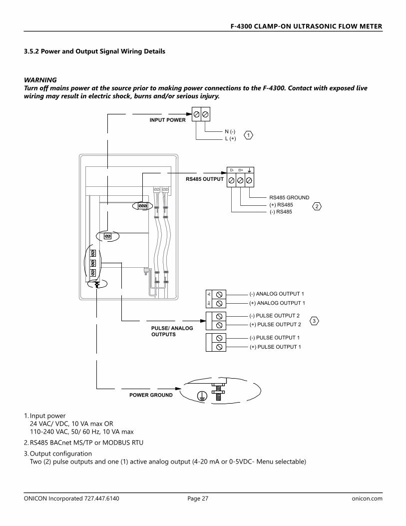
Sensor – Choose SE16A for 10 Series transducer or SE16B for 20 Series transducer
Angle – Only available when SE16B selected above- Select the angle of the transducer. Contact ONICON for assistance defining what angle sensors you have.
Fluid – Select between Water or Other. When Water is selected, the speed of sound of the fluid is determined based on the temperature entered later in this Setup menu.
Vel@25C – Only appears if “Other” was selected at the Fluid option. Enter the speed of sound of the fluid at 77°F (25°C). Units are defined by what was selected in the Units/Mode menu.dV/C – Only appears if “Other” was selected at the Fluid option. This defines how much the speed of sound varies per degree C. This should be left at 0 unless the speed of sound change of the fluid is linear with respect to temperature.
Temp Mode – Defaulted at "Fixed"Temp – Temperature of the fluid. If “Water” was selected at Fluid, enter the water temperature. If “Other” was selected at Fluid, enter 25.0°C or 77.0°F for the fluid temperature, depending on units of measurement selected.
Pipe – Select the pipe material. Options: Carbon Steel, Brass, Aluminum, Acrylic, ABS, Other, Stainless 430, Stainless 410, Stainless 347, Stainless 316, Stainless 304, Stainless 303, Stainless 302, Mild Steel, PVC, Poly HD, Poly LD, Nylon, Iron, FRP, Ductile Iron, CPVC, Copper, Cast Iron.
Vel – If “Other” pipe material was chosen, enter the sonic velocity of the pipe material here. Units of measurement are defined in the Setup menu. OD – Enter the pipe’s outside diameter in units defined in the Setup menu. Charts with standard pipe sizes based on schedule are provided in the appendix of this manual.Wall – Enter the pipe’s wall thickness in units defined in the Setup menu. Charts with standard pipe sizes based on schedule are provided in the appendix of this manual.
Lining – Select whether or not the pipe the meter is being mounted to has a liner. Options: None, Tar Epoxy, Rubber, Mortar, Asb Cement, Other
Thick - Enter the liner thickness in units defined in the Setup menu. Only appears if Lining is not “None”.
4.5 PROGRAMMING MENU PAGES (Continued)
Setup Menu PageThe Setup page allows the user to define the type of transducer used and to define process conditions like pipe material, size, fluid type and temperature. After these settings are defined, the spacing distance will be displayed on this page, and once the transducers are installed the meter will be ready to work.
All of these settings are pre-configured by ONICON before shipment. These settings should only be adjusted if the process conditions provided to ONICON at time of order were incorrect, or different transducers were supplied for field installation.
--Setup-------------
Sensor SE16B
Angle 37
Fluid Water
Temp Mode Fixed
Temp 77.0 F
Pipe PVC
OD 4.5000 in
Wall 0.2500 in
Lining None
Crossings 2
Zero Tare No
Sens Space 2.299in
Velocity 0.00 ft/s
Signal Strength100 %

F-4300 CLAMP-ON ULTRASONIC FLOW METER
ONICON Incorporated 727.447.6140 Page 36 onicon.com
--Setup-------------
Sensor SE16B
Angle 37
Fluid Water
Temp Mode Fixed
Temp 77.0 F
Pipe PVC
OD 4.5000 in
Wall 0.2500 in
Lining None
Crossings 2
Zero Tare No
Sens Space 2.299in
Velocity 0.00 ft/s
Signal Strength100 %
4.5 PROGRAMMING MENU PAGES (Continued)
Crossings – Defines the number of times the ultrasonic signal crosses the inside of the pipe. The first choice used should be 2 or 4 crosses.
1 crossing is a “Z” or “Direct” mode, 2 crossings is a “V” or “Reflect” mode, and 4 crossings is a “W” or “Double Reflect” mode. 1 crossing will provide the largest signal strength but more diligence is required to mount the transducers properly. 2 crossings provide the easiest means to mount the transducers, averages some of the flow distortions in the pipe, but attenuates the signal more than 1 cross. This is the default and ONICON recommended configuration.4 crossings provide even more averaging than 2 crosses. 4 crosses will not be an option unless the transducers overlap in a 2 cross setup, which is dependent on pipe settings (Refer to the drawings on pages 10 and 11) and fluid sonic velocity.
Zero Tare – Used to suppress readings or fluctuations at zero flow. Do not enable this function unless flow in the pipe has been valved to 0, and the pipe is full. Sens Space – This function is not editable. This value will automatically calculate after the sensor type, angle, fluid type and temperature, pipe material and size, and number of crossings is defined. This distance is defined as the measurement between the inside of both transducers. Because the meter comes pre-programmed from ONICON, this number is already defined for you on the Site Installation Details sheet. However, if any of the factors listed above are changed in the field, you will need to change the transducer spacing to the new number provided here.Velocity – After mounting the transducers and connecting the transducer cable, you will be able to see the flow velocity in real-time once flow is established.Signal Strength – After mounting the transducers and connecting the transducer cable, you will be able to see the signal strength in real-time. The pipe must be full of water to get a valid signal strength reading.
F-4300 CLAMP-ON ULTRASONIC FLOW METER
ONICON Incorporated 727.447.6140 Page 37 onicon.com
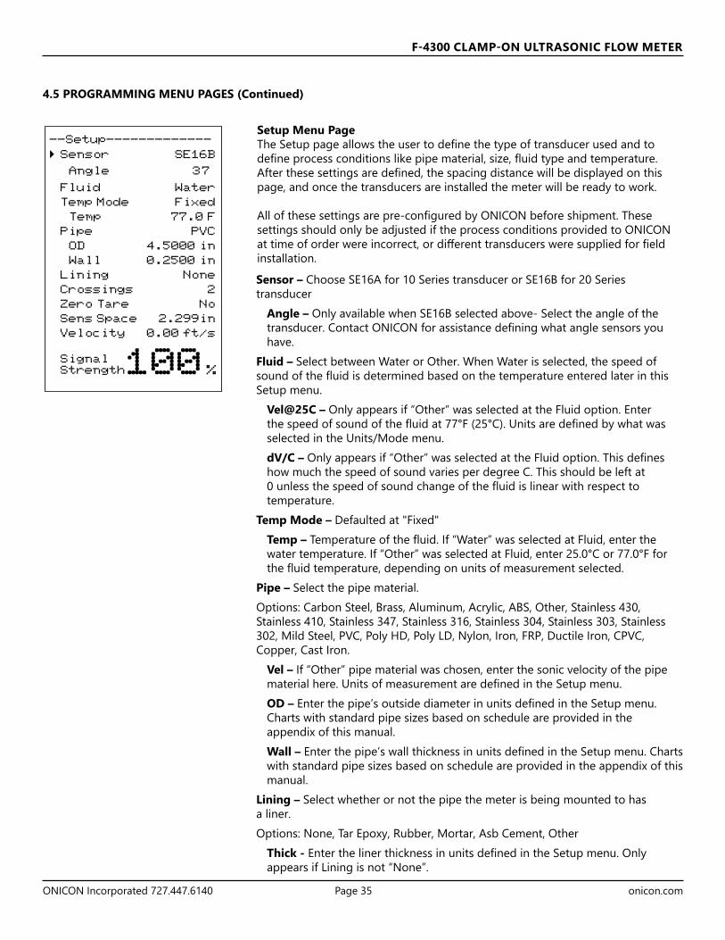
Calibration Menu PageThe calibration menu defines the behavior of the flow measurement and its related outputs.Mode – Shows the Mode which was selected in the Units/Mode menu. Could be “Flow” or “Velocity.”
20 mA at or 5V at – Enter the desired flow rate to be equal to 20 mA or 5V.4 mA at or 0V at – Enter the desired flow rate to be equal to 4 mA or 0V. Typically, 0 flow/velocity, but could be a negative value if you wanted the 4-20 mA/0-5V output to represent more than one direction.
LOS Time - Value which suppress intermittent loss of signal.Example: Systems with high concentrations of undissolved gasses will cause fluctuations in signal strength when the gasses move past the ultrasonic signal. If a complete loss of signal is experienced, the F-4300 will hold the last valid reading for the duration of the LOS Time.If the signal strength returns before the LOS Time is expired, because the ultrasonic signal is no longer being impeded, the meter will return to normal operation automatically.If signal strength does not return after the LOS Time has expired, the meter will report zero flow on the LCD display and outputs, and produce a Low Signal alarm.Default LOS Time is 30 seconds, and the value can be set between 0 and 99 seconds.Min Flow – Value which if the measured flow rate falls below, the meter will force the reading and outputs to 0. Units match those configured in the Units/Mode menu. The default and recommended value is the volumetric flow rate equivalent to 0.1 ft/sec in your pipe size.Damping – The damping value stabilizes the flow rate on the display and analog output. For applications with poor straight run, use a higher dampening value to steady the flow reading. Lower dampening values should be used in applications where you want a faster response from the meter. The default dampening value is 20%.Cal Constant – Calibration constant defined during calibration. This value shouldn’t be changed unless ONICON support has requested to do so.
4.5 PROGRAMMING MENU PAGES (Continued)
--Calibration-------
Mode Flow
20mA 500.00 USG/m
4mA 0.00 USG/m
LOS Time 10 sec
Min Flow 4.00 USG/m
Damping
Mode FIR
Percent 10%
Window 1.0 ft/s
Cal Constant 1.00

F-4300 CLAMP-ON ULTRASONIC FLOW METER
ONICON Incorporated 727.447.6140 Page 38 onicon.com
4.5 PROGRAMMING MENU PAGES (Continued)
Relay Parameters Menu PageThe relay parameters page is where changes can be made to the pulse outputs available with the F-4300.Relay – Defines which pulse output you are making changes to, either 1 or 2.Function – Defines the behavior of the pulse output selected at the Relay option. Choices:
On – Pulse is always engagedOff – Pulse is always disengagedPulse – Scaled pulse. Define how many gallons must be measured before a pulse occurs. Pulse duration = 50 ms; max Hz = 10Flow – Pulse output functions as a flow alarm. You will need to define when the alarm comes ON, and when the alarm will turn OFF again. Examples: High Flow Alarm: ON = 300 GPM, OFF = 250 GPMFlow goes above 300 GPM and the pulse output latches ON. It will not turn OFF until flow goes below 250 GPM.Direction- Direction Switch ON = +0.1 GPM, OFF = -0.1 GPMAny flow above 0.1 GPM will cause the pulse to turn ON, and it will turn off should flow reverse.
Data Logging Menu PageThe Data Logging page allows configuration of the data logger. Options include what is being logged, how often it is being logged, and the date settings.
--Relay Parameters--
Relay 1
Function Flow
On 1000 USG
Off 0.000 USG
--Data Logging-------
Log Site ID 01
Mode Flow
File Format .LG2
Date Mar. 20/2020
Time 12:28:41
Interval 30sec
Data Log Logging
IMPORTANT NOTEThe logger must be configured in a specific order in order to function correctly:1. Set the Log Site ID, Mode, File Format, Date, Time, and Interval to the desired option.2. Under Data Log, select “Delete”3. Under Data Log, select “Start”4. Deploying the logger in any other order will compromise the settings you’ve chosen.

F-4300 CLAMP-ON ULTRASONIC FLOW METER
ONICON Incorporated 727.447.6140 Page 39 onicon.com
Log Site ID – Provide a number to the log site you’re creating. Can be any number between 00-99.Mode – Define what is being logged. Options: Flow, Velocity.File Format – Define how you will want the data presented when downloaded. Choose .LG2 when you will be looking at the log data with the ONICON Logger Utility software. Choose .CSV when you will be loading the data directly into an Excel spreadsheet for manipulation and graphing.Date – Configure today’s date. Format: Month Day/Year.Time – Configure the time. Format: hh:mm:ss. Range: 00:00:00-23:59:59.Interval – Define how often the unit selected under Mode will log. Options: 10 sec, 30 sec, 1 min, 2 min, 5 min, 10 min, 15 min, 30 min, and 60 min.At the fastest interval, 10 sec, the logger will last 8.5 years before it is full. However, if you are curious about the % log used, it is available in the Messages Menu accessible from the Run Screen by pressing the .Although the logger storage capability is quite extensive, ONICON recommends not using an interval more resolute than required, as downloading a large log file could present data transfer problems and corrupted data. Data Log – Stop, Start or Delete the log file.
4.5 PROGRAMMING MENU PAGES (Continued)
--Communication-----
Protocol Modbus
Address 001
BPS 9600
Parity Even
Stop Bits 1
Communications Menu PageThe communications menu provides the means to select the serial output of the meter, and the addressing and communication speed.Protocol – Select the protocol for the serial communications. Options: OFF, MODBUS, BACnet DevID – Only available if BACnet was the selected Protocol. This is the Device ID which must be unique for the device across the whole BACnet network. Range: 0-4,194,302.MAC Address – Only available if BACnet was the selected Protocol. This is the RS485 bus address for the BACnet MS/TP communications. Range: 0-127 for master devices, 128-254 for slave devices.BPS – Baud Rate, or Bits Per Second. Defines the speed of communication on the BUS. Must be the same for all devices on the BUS. Options: 9600, 19200, 38400, 76800.
--Data Logging-------
Log Site ID 01
Mode Flow
File Format .LG2
Date Mar. 20/2020
Time 12:28:41
Interval 30sec
Data Log Logging

F-4300 CLAMP-ON ULTRASONIC FLOW METER
ONICON Incorporated 727.447.6140 Page 40 onicon.com
Special Functions Menu PageLanguage – Select the language for the menus and displays. Options: English, French, Spanish.Analog Out – Defines the analog output type. Options: 4-20 mA, 0-5V.Backlight – Raise or lower the brightness of the display backlight. Options: Off, High, Med, Low, Key Hi/Lo (Brightness goes to High after a keypress, then Low after 1 minute of no button presses), Key High, Key Med, and Key Low (Brightness goes to specified value after keypress, then OFF after 1 minute). Reset Totalizer – Select YES to reset totalizer. YES will flash two times after pressing to indicate the action was accepted.Neg. Totals – Selecting NO will cause the totalizer to ignore flow rates in the negative direction. Only positive flows will accumulate the totalizer. Selecting YES will cause negative flows to deduct from the totalizer. Totalizer values can achieve a negative value if negative totals are greater than positive totals.Rev.FLow - Select ON/ OFF to enable/ disable flow direction measurement. Select INVERT to invert the sense of the flow measurement.Capture Par - This function captures the programming parameters in the meter. Select YES, then wait for INSRT USB to appear, then insert a USB drive into the USB port to transfer the parameters. After Saving flashes, DONE will appear on the screen, meaning it it safe to remove the USB.Capture WF - This function captures the ultrasonic signal so that it can be evaluated by ONICON. Contact ONICON for the instructions.Restore Defaults – Selecting YES will cause all of the programming settings to revert to the factory default. These defaults are different than the programming ONICON performed at the factory before the meter was shipped. New Password – This function allows a new password to be set. This password protects the programming menu access from the Main Display. The default value is 0000. Range: 0000-9999. Do not lose the password if changed, in case you need to return to the programming menu at a later date.
Simulation Menu PageThe simulation menu page is used to generate flow rates independent of the actual measurement in the system, in order to test output signals. Any simulated flow rate is only active while the Simulation Menu is open. Once the menu is exited, the flow rate and output signal behavior will return to that actually measured by the meter.Test – This function defines how the simulation mode will be tested. Options: Actual, Maximum, Minimum.When Actual is selected, any flow rate which is currently present will be displayed on the screen, and the outputs associated with that flow rate is also displayed. Alternatively, you can move the cursor to the Flow option, press to enter the option, and then set a flow rate manually. After is pressed, the analog output and pulse outputs will be driven by the set flow rate.When Maximum is selected, the flow rate will be driven to the 20 mA/5V value configured in the Calibration Menu Page.When Minimum is selected, the flow rate will be driven to the 4 mA/0V value configured in the Calibration Menu Page.
4.5 PROGRAMMING MENU PAGES (Continued)
--Special Functions-
Language English
Analog Out 4-20mA
Backlight High
Reset Totalizer NO
Neg. Totals NO
Rev. Flow OFF
Capture Par NO
Capture WF NO
Restore Defaults NO
New Password 0000
--Simulation--------
Test Actual
Flow 250USG/m
4-20mA Flow 5.60mA
Relays 1 2 3 4 5 6

F-4300 CLAMP-ON ULTRASONIC FLOW METER
ONICON Incorporated 727.447.6140 Page 41 onicon.com
Configuration Menu PageThe configuration menu page stores the serial number and electronics information for the F-4300. All of the values in this menu are read-only.Serial # - Serial number of the F-4300. This value is also present on the outside of the enclosure, and inside the door.Utility – Revision of the utility card. The utility card is the vertical card on the left hand side of the chassis. It connects to the LCD display, and has the analog and pulse outputs on it.Transit Time – Revision of the transit time card. The Transit time card is the topmost horizontal card, with the two connectors attached to the Triax cable.CommBoard ––Revision of the communications card. Relays – Lists the number of pulse outputs present on the meter. This should always be 2.Analog Out – Lists the number of analog outputs present on the meter. This should always be 1.
SECTION 5.0 BACNET MS/TPBACnet MS/TP, serial interface connections are connected at the RS485 card’s terminal block.
Transceiver: 2-wire, half-duplex BACnet® address (MAC address) range: 1 - 247 (Default: 017)Device Instance: 0 - 4,194,302 (Default: 57017)Baud rate: 9600, 19200, 38400 or 76800 (Default: 38400)Termination: 120 ohms or none (Default: none) Jumper JP1 position 1 + 2 = OFF Jumper JP1 position 2 + 3 = ONBiasing: NoneFlow control: None
RS485 Output Card
4.5 PROGRAMMING MENU PAGES (Continued)
--Configuration----- Serial# 12345
Utility 1.26.0.5
Transit Time 1.38.1
CommBoard 1.18.0
Relays 2
Analog Out 1

F-4300 CLAMP-ON ULTRASONIC FLOW METER
ONICON Incorporated 727.447.6140 Page 42 onicon.com
5.2 PROTOCOL IMPLEMENTATION STATEMENT
5.1 BACNET OBJECT TYPESBACnet Object Type and Number of Objects Implemented
Device: 1
Analog Input: 3
Analog Value: 5
Binary Value: 3
Multistate Object: 2
BACnet Protocol Revision: 10
Device Profile (Annex L): BACnet® Application Specific Controller (B-ASC)
MS/TP master (Clause 9), baud rate(s): 9600, 19200, 38400 & 76800
Device Address Binding: No
BBMD support registration by Foreign Devices: No
Character Set Supported: ANSI X3.4
BACnet Interoperability Building Blocks Supported (Annex K):
Data Sharing-ReadProperty-B (DS-RP-B)
Data Sharing - ReadProperty Multiple - B (DS-RPM-B)
Data Sharing-WriteProperty-B (DS-WP-B)
Data Sharing - WriteProperty Multiple - B (DS-WPM-B)
Device Management-Dynamic Device Binding - B (DM-DDB-B)
Device Management-Dynamic Object Binding - B (DM-DOB-B)
Device Management-DeviceCommunicationControl-B (DM-DCC-B)
Device Management-Time Synchronization - B (DM-TS-B)
Device Management - UTC Time Synchronization – B (DM-UTC-B)
Standard Object Types Supported:
Device Object Binary Value Object
Analog Input Object Multi-State Value
Analog Value Object

F-4300 CLAMP-ON ULTRASONIC FLOW METER
ONICON Incorporated 727.447.6140 Page 43 onicon.com
5.3 DEVICE OBJECT
Property Default Value Read-only or Writable
Comment
Object Identifier 57017 Writable 0-4,194,303Object Name ONICON F-4300-XXXXXX Read-only XXXX= Serial
No.Object Type Device Read-onlySystem Status Operational Read-onlyVendor Name ONICON Inc. Read-onlyModel Name F-4300 Read-onlyFirmware Rev. 000.006.000 Read-onlyLocation Customer Location Writable 32 char. MaxDescription Customer Description Writable 32 char. MaxProtocol Version 1 Read-onlyProtocol Revision 10 Read-onlyServices Supported Read property, Read property multiple,
Write property, Write property multiple, Read range, Who-has, I have, Who-is, I-am, Device communications control, Time synchronization, UTC time synchronization
Read-only
Object Types Supported Analog input, Analog value, Binary input, Device, Multi-state value
Read-only
Object List (Device, 57017), (analog input, 1-3), (analog value, 1-5), (binary value, 1-3), (multi state value, 1-2)
Read-only
Max ADPU Length 480 Read-onlySegmentation Supported NO-SEGMENTATION (2) Read-onlyLocal Time Device current time Read-onlyLocal Date Device current date Read-onlyUTC Offset -300 WritableDaylight Savings Status False WritableAPDU Timeout 6000 Read-only# of APDU Retries 3 WritableMax Master 127 WritableDevice Address Binding Read-onlyDatabase Revision 1 Read-only

F-4300 CLAMP-ON ULTRASONIC FLOW METER
ONICON Incorporated 727.447.6140 Page 44 onicon.com
5.4 ANALOG INPUT(S)
Analog Input Objects
Property Default Value Read-only or Writable
Comment
Object Identifier Analog-input,1 to analog-input, 3 Read-onlyObject Name Various Read-onlyObject Type Analog-input Read-onlyPresent Value REAL WritableDescription Various Read-onlyStatus Flags (F,F,F,F) Read-onlyEvent State Normal Read-onlyReliability No-fault-detected Read-onlyOut-of-Service FALSE WritableUpdate interval 100 Read-onlyUnits Various Read-onlyMin-Present-Value -1000000000 Read-onlyMax-Present-Value 1000000000 Read-onlyResolution 0.001 Read-only
Object Identifier FunctionAnalog input 1 Flow velocityAnalog input 2 Flow rateAnalog input 3 Sonic velocity
BACnet Engineering Units for Analog InputsFlow Velocity: ft/s, m/sVolume rate: gpm, L/s, ms/m, ft³/m, L/mSonic velocity: ft/s, m/s

F-4300 CLAMP-ON ULTRASONIC FLOW METER
ONICON Incorporated 727.447.6140 Page 45 onicon.com
5.5 ANALOG VALUE(S)
Property Default Value Read-only or Writable
Comment
Object Identifier Analog-value,1 to analog-value, 5 Read-onlyObject Name Various Read-onlyObject Type Analog-value Read-onlyPresent Value REAL WritableDescription Various Read-onlyStatus Flags (F,F,F,F) Read-onlyEvent State Normal Read-onlyReliability No-fault-detected Read-onlyOut-of-Service FALSE WritableUnits Various Read-onlyPriority Array {NULL, NULL, NULL, NULL, NULL, NULL,
NULL, NULL, NULL, NULL, NULL, NULL, NULL, NULL, NULL, NULL}
Read-only
Relinquish Default 0 Read-only
Analog Value Objects
Object Identifier Single Mode FunctionAnalog value 1 Volume total Analog value 2 Logging used Analog value 3 Previous day average flowAnalog value 4 Previous day volumeAnalog value 5 Signal strength
BACnet Engineering Units for Analog Values Volume total: gallons, liters, cubic meters, cubic feetLogging Used: Percent (0-100)Previous day average flow: gpm, L/s, m³/m, ft³/m, L/mPrevious day volume: gallons, liters, cubic meters, cubic feetSignal Strength: Percent (0-100)

F-4300 CLAMP-ON ULTRASONIC FLOW METER
ONICON Incorporated 727.447.6140 Page 46 onicon.com
5.6 BINARY VALUE(S)
Property Default Value Read-only or Writable
Comment
Object Identifier Binary-value,1 to binary-value, 3 Read-onlyObject Name Various Read-onlyObject Type Binary-value Read-onlyPresent Value 0 WritableDescription Various Read-onlyStatus Flags (F,F,F,F) Read-onlyEvent State Normal Read-onlyReliability No-fault-detected Read-onlyOut-of-Service FALSE WritableElapsed Active Time Various Read-onlyPriority Array (NULL, NULL, NULL, NULL, NULL, NULL,
NULL, NULL, NULL, NULL, NULL, NULL, NULL, NULL, NULL, NULL)
Read-only
Relinquish Default 0 Read-only
Binary Value ObjectsObject Identifier Description Notes Binary value 1 Reset volume total Write 1 = reset totalBinary value 2 Pulse output 2 status 0 = Pulse inactive, 1 = Pulse activeBinary value 3 Pulse output 2 status 0 = Pulse inactive, 1 = Pulse active
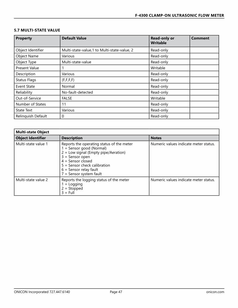
F-4300 CLAMP-ON ULTRASONIC FLOW METER
ONICON Incorporated 727.447.6140 Page 47 onicon.com
Property Default Value Read-only or Writable
Comment
Object Identifier Multi-state-value,1 to Multi-state-value, 2 Read-onlyObject Name Various Read-onlyObject Type Multi-state-value Read-onlyPresent Value 1 WritableDescription Various Read-onlyStatus Flags (F,F,F,F) Read-onlyEvent State Normal Read-onlyReliability No-fault-detected Read-onlyOut-of-Service FALSE WritableNumber of States 11 Read-onlyState Text Various Read-onlyRelinquish Default 0 Read-only
5.7 MULTI-STATE VALUE
Multi-state ObjectObject Identifier Description Notes Multi-state value 1 Reports the operating status of the meter
1 = Sensor good (Normal)2 = Low signal (Empty pipe/Aeration)3 = Sensor open4 = Sensor closed5 = Sensor check calibration6 = Sensor relay fault7 = Sensor system fault
Numeric values indicate meter status.
Multi-state value 2 Reports the logging status of the meter 1 = Logging2 = Stopped3 = Full
Numeric values indicate meter status.

F-4300 CLAMP-ON ULTRASONIC FLOW METER
ONICON Incorporated 727.447.6140 Page 48 onicon.com
SECTION 6.0: MODBUSMODBUS serial interface connections are connected at the RS485 or TCP/IP card’s terminal block.
6.1 MODBUS RTU RS485Transceiver: 2-wire, half-duplexData format: 8 Data Bits, 1 or 2 Stop Bits (Default: 1 Stop Bits)Parity: None, Odd, or Even (Default: Even)MODBUS MAC address (device address) range: 1 - 255 (Default: 017)Baud rate: 9600, 19200, 38400, or 76800 (Default: 38400)Termination: 120 ohms or none (Default: none)Jumper JP1 position 1 + 2 = OFFJumper JP1 position 2 + 3 = ONBiasing: NoneFlow control: None
6.2 MODBUS TCP/IPTransceiver: 10/100 Base-TX and RJ45 connectorPort: 502Parity: NoneMODBUS MAC Address range: 1-255 (Default: 017)Baud rate: 38400IP Address: 192.168.255.1Mask: 255.255.0.0Gateway: 192.168.0.1

F-4300 CLAMP-ON ULTRASONIC FLOW METER
ONICON Incorporated 727.447.6140 Page 49 onicon.com
6.2.1 IP Address SettingChanging the IP address of the F-4300 requires the use of a PC with an Ethernet card and an available port. The default IP configuration of the F-4300 is as follows:IP Address 192.168.255.1Mask 255.255.0.0Gateway 192.168.0.1
The interface shown above is used to configure the IP settings on the F-4300. The Login Password is admin (case sensitive). Press Submit after entering the password, and the following page appears:
To change these IP address settings:• Connect the Ethernet cable to the RJ45 jack on the TCP/IP card• Change the adapter settings in your PC as shown:
Next, open a web browser, and navigate to IP address 192.168.255.1. The following page will appear:

F-4300 CLAMP-ON ULTRASONIC FLOW METER
ONICON Incorporated 727.447.6140 Page 50 onicon.com
Seven pages are available from the main menu:Home – The page you currently see. This page is not used to configure the IP address.Port1 – Not used.Network – This page allows you to change the IP address settings.Filter – Not used.Monitor – Not used.Password – This page can be used to change the password from the default admin.Logout – Press this button to logout of the F-4300 IP configurator.Press the Network button to arrive at the following page:Within the IP Address Selection section, you can configure the IP settings for the F-4300’s MODBUS communications.
Address Type – Choose between Static IP, and DHCP. The Static IP Address, Subnet Mask, and Default Gateway will become un-editable if DHCP is selected. After the configuration has been updated, press the Update Settings button to save the changes. Document the configuration chosen. After pressing the update button, if you need to access these settings again, you must go back into your PC’s IP setting page and change the IP address and subnet to match the network the F-4300 is set for. After you are done making configuration changes, you are ready to connect the F-4300 to the MODBUS TCP/IP network.
6.2.1 IP Address Setting (continued)
The interface shown above is used to configure the IP settings on the F-4300. The Login Password is admin (case sensitive). Press Submit after entering the password, and the following page appears:

F-4300 CLAMP-ON ULTRASONIC FLOW METER
ONICON Incorporated 727.447.6140 Page 51 onicon.com
Function Codes Supported:01 - Read Coil(s)02 - Read Discreet Input(s)04 - Read Input Register(s)05 - Write Single Coil06 - Write Single Register15 - Write Multiple Coils16 - Write Multiple Registers17 - Report Slave ID
Engineering Units Abbreviation Engineering Units AbbreviationVolume Rate (Flow) Volume TotalGallons per minute GPM Gallons GalCubic meters per hour m3/hr Liters LitersCubic feet per minute ft3/min Cubic Feet ft3
Liters per second L/s Cubic Meters m3
Liters per minute L/mVelocity (Flow velocity, Fluid speed of sound)Feet per second ft/sMeters per second m/s
6.3 UNITS AND FUNCTIONS

F-4300 CLAMP-ON ULTRASONIC FLOW METER
ONICON Incorporated 727.447.6140 Page 52 onicon.com
6.4 MODBUS MEMORY MAP
Register Address
Description Register Type
Data Range
Over Range
Read/Write
Comments
1 Reset Volume Total
Coil NA NA Read/Write
Turn coil ON (1) to reset total on F-4300. Turn coil to OFF (0) once reset is complete.
Register Address
Description Register Type
Data Range
Over Range
Read/Write
Comments
10001 Pulse Output 1 Status
Discreet Input
NA NA Read (0) indicates pulse output is OFF or inactive. (1) indicates pulse output is ON or active.
10002 Pulse Output 2 Status
Discreet Input
NA NA Read (0) indicates pulse output is OFF or inactive. (1) indicates pulse output is ON or active.
Register Address
Description Register Type Format Type Comments
30001 Flow velocity – ft/s Input Register Floating Point (1 of 2)30002 Flow velocity – ft/s Input Register Floating Point (2 of 2)30003 Flow velocity – m/s Input Register Floating Point (1 of 2)30004 Flow velocity – m/s Input Register Floating Point (2 of 2)30101 Flow rate - GPM Input Register Floating Point (1 of 2)30102 Flow rate - GPM Input Register Floating Point (2 of 2)30103 Flow rate – L/s Input Register Floating Point (1 of 2)30104 Flow rate – L/s Input Register Floating Point (2 of 2)30105 Flow rate – ft3/min Input Register Floating Point (1 of 2)30106 Flow rate – ft3/min Input Register Floating Point (2 of 2)30107 Flow rate – m3/hr Input Register Floating Point (1 of 2)30108 Flow rate – m3/hr Input Register Floating Point (2 of 2)30129 Flow rate - L/m Input Register Floating Point (1 of 2)30130 Flow rate - L/m Input Register Floating Point (2 of 2)30165 Last 24 Hour Average Flow Rate - GPM Input Register Floating Point (1 of 2)30166 Last 24 Hour Average Flow Rate - GPM Input Register Floating Point (2 of 2)30167 Last 24 Hour Average Flow Rate - L/s Input Register Floating Point (1 of 2)30168 Last 24 Hour Average Flow Rate - L/s Input Register Floating Point (2 of 2)30169 Last 24 Hour Average Flow Rate - ft3/min Input Register Floating Point (1 of 2)30170 Last 24 Hour Average Flow Rate - ft3/min Input Register Floating Point (2 of 2)30171 Last 24 Hour Average Flow Rate - m3/hr Input Register Floating Point (1 of 2)30172 Last 24 Hour Average Flow Rate - m3/hr Input Register Floating Point (2 of 2)30193 Last 24 Hour Average Flow Rate - L/m Input Register Floating Point (1 of 2)30194 Last 24 Hour Average Flow Rate - L/m Input Register Floating Point (1 of 2)30301 Volume Total - Gal Input Register Floating Point (1 of 2) 30302 Volume Total - Gal Input Register Floating Point (2 of 2) Register Address
Description Register Type Format Type Comments
30303 Volume Total - Liters Input Register Floating Point (1 of 2) 30304 Volume Total - Liters Input Register Floating Point (2 of 2) 30305 Volume Total - ft3 Input Register Floating Point (1 of 2)

F-4300 CLAMP-ON ULTRASONIC FLOW METER
ONICON Incorporated 727.447.6140 Page 53 onicon.com
30306 Volume Total - ft3 Input Register Floating Point (2 of 2) 30307 Volume Total - m3 Input Register Floating Point (1 of 2) 30308 Volume Total - m3 Input Register Floating Point (2 of 2) 30317 Last 24 Hour Volume Total - Gal Input Register Floating Point (1 of 2) 30318 Last 24 Hour Volume Total - Gal Input Register Floating Point (2 of 2) 30319 Last 24 Hour Volume Total - Liters Input Register Floating Point (1 of 2) 30320 Last 24 Hour Volume Total - Liters Input Register Floating Point (2 of 2) 30321 Last 24 Hour Volume Total - ft3 Input Register Floating Point (1 of 2) 30322 Last 24 Hour Volume Total - ft3 Input Register Floating Point (2 of 2) 30323 Last 24 Hour Volume Total - m3 Input Register Floating Point (1 of 2) 30324 Last 24 Hour Volume Total - m3 Input Register Floating Point (2 of 2) 30901 Signal Strength - % Input Register Integer 0-10030919 Adjusted Speed of Sound - ft/sec Input Register Floating Point (1 of 2) 30920 Adjusted Speed of Sound - ft/sec Input Register Floating Point (2 of 2) 30921 Adjusted Speed of Sound - m/sec Input Register Floating Point (1 of 2) 30922 Adjusted Speed of Sound - m/sec Input Register Floating Point (2 of 2)30923 Sensor Status Input Register Index 0 = Sensor Good
4 = Sensor Open5 = Sensor Short7 = Low Signal
30925 Logging Status Input Register Index 0 = Stopped1 = Active2 = Full
30926 Logging Used - % Input Register Floating Point (1 of 2)30927 Logging Used - % Input Register Floating Point (2 of 2)30947 Velocity Units Input Register Index 0 = ft/s
1 = m/s
30948 Flow Units Input Register Index 0 = GPM1 = L/s2 = ft3/min3 = m3/hr14 = L/m
30949 Linear Units Input Register Index 0 = Feet1 = Inches2 = Millimeters3 = Meters
30950 Volume Units Input Register Index 0 = ft3
1 = Gallons5 = m3
6 = Liters
30951 Time Units Input Register Index 0 = Second1 = Minute2 = Hour
6.5 REPORT SLAVE ID FUNCTION CODEThe MODBUS implementation of the F-4300 supports the use of function code 17, Report Slave ID.
When a message is sent to the F-4300 requesting to report the slave ID, the following information is returned after converting the HEX meter response to ASCII:
“Transit-Time Flowmeter - XXXXXX” where XXXXXX = the serial number of the F-4300 being polled.
6.4 MODBUS MEMORY MAP (Continued)

F-4300 CLAMP-ON ULTRASONIC FLOW METER
ONICON Incorporated 727.447.6140 Page 54 onicon.com
SECTION 7.0: COMMISSIONINGPlease read all installation instructions carefully before proceeding. Wiring diagrams are located in an earlier section of this manual. Use the meter certificate of calibration to verify that the specified installation & operating parameters match the actual conditions at the location where the meter is installed. A worksheet for checking off these steps and recording measured values is located in section 7.3.
7.1 HELPFUL HINTS FOR START-UP AND COMMISSIONINGPlease read these helpful hints before proceeding with the commissioning procedure on the next page.1. ONICON flow meters are individually calibrated for a particular application. Be sure to verify the pipe size and location.2. The ultrasonic flow sensing systems will not work with an empty pipe.3. When measuring analog output signals, remember that current (mA) must be measured in series, while voltage is
measured in parallel. If the 4-20 mA signal is already connected to a control system, you must break the connection and measure the signal in series.
7.2 COMMISSIONING PROCEDUREPlease read the entire procedure before proceeding. A worksheet for checking off the following steps and recording measured values provided in Section 7.3.
1. Confirm that the flow meter is being installed in accordance with Sections 1.7 and 3.3 of this manual.
Confirm that the installation location is removed from any sources of strong electrical interference and that the enclosure is mounted on a vibration-free surface. Confirm that the transducer signal cables are run in dedicated conduit without other signal or power cables.
2. Confirm flow meter location. Confirm adequate straight pipe run to achieve desired results. Is the meter located in the correct location as required by the plans? Compare actual straight pipe upstream and downstream of the meter location to recommended distances identified in this manual. Contact ONICON to discuss specifics of your application. If straight pipe run is very short, consult ONICON PRIOR to commissioning the meter.
3. Confirm pipe size. Confirm that the meter is tagged for the pipe size in which it is installed. When in doubt, measure the circumference of the pipe. Pipe O.D. = (circumference / 3.14) – (insulation thickness x 2).
4. Verify the type of fluid used in the piping system.
Confirm that the fluid specified on the flow meter certificate of calibration matches the fluid flowing in the piping system.
5. Confirm control system programming.
Confirm that the control system input points are properly configured for the analog output range, pulse scale factor and/or relay output function identified on the calibration certificate & meter tag.
6. Confirm connection to the correct ONICON display or BTU meter (if ordered).
Confirm that the flow meter serial number matches the ONICON display or BTU meter serial number (when ordered together).
7. Verify output signal wiring. Verify that the wiring is correct as shown in this manual and/or the additional wiring diagram provided with the ONICON display or BTU meter. If in doubt, contact ONICON for assistance before proceeding further.
8. Confirm correct supply voltage.
Verify that the supply voltage is within specified limits. The F-4300 could have been ordered with a low voltage or high voltage board.
The following steps require flow in the pipe. Flow signal readings should be taken while holding the flow rate constant, if possible. Otherwise, take the various output readings as quickly as possible.
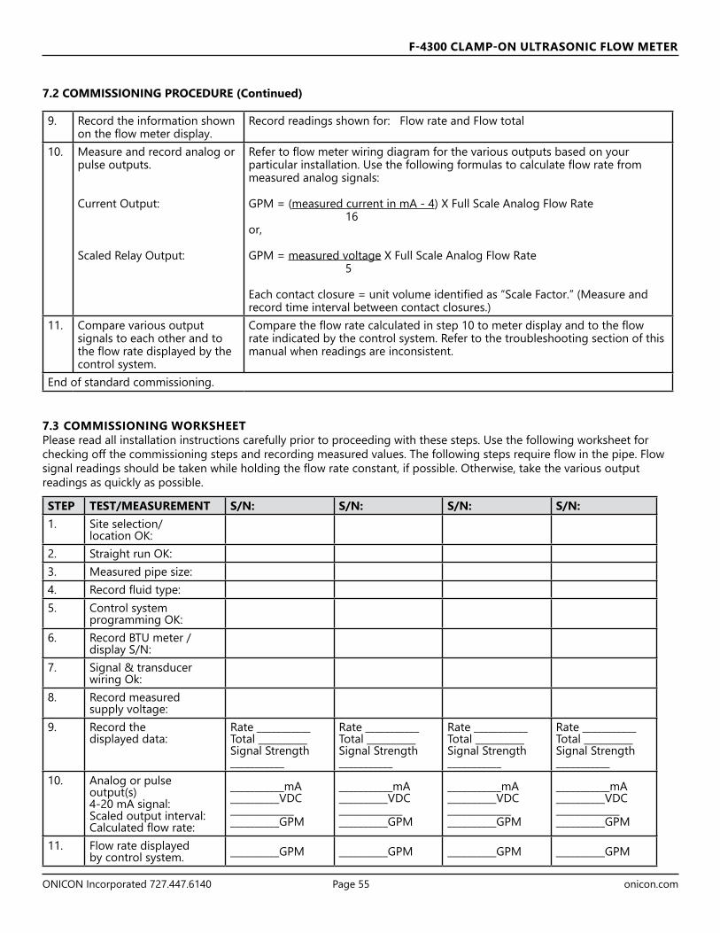
F-4300 CLAMP-ON ULTRASONIC FLOW METER
ONICON Incorporated 727.447.6140 Page 55 onicon.com
9. Record the information shown on the flow meter display.
Record readings shown for: Flow rate and Flow total
10. Measure and record analog or pulse outputs.
Current Output:
Scaled Relay Output:
Refer to flow meter wiring diagram for the various outputs based on your particular installation. Use the following formulas to calculate flow rate from measured analog signals:
GPM = (measured current in mA - 4) X Full Scale Analog Flow Rate 16or,
GPM = measured voltage X Full Scale Analog Flow Rate 5
Each contact closure = unit volume identified as “Scale Factor.” (Measure and record time interval between contact closures.)
11. Compare various output signals to each other and to the flow rate displayed by the control system.
Compare the flow rate calculated in step 10 to meter display and to the flow rate indicated by the control system. Refer to the troubleshooting section of this manual when readings are inconsistent.
End of standard commissioning.
7.3 COMMISSIONING WORKSHEETPlease read all installation instructions carefully prior to proceeding with these steps. Use the following worksheet for checking off the commissioning steps and recording measured values. The following steps require flow in the pipe. Flow signal readings should be taken while holding the flow rate constant, if possible. Otherwise, take the various output readings as quickly as possible.
STEP TEST/MEASUREMENT S/N: S/N: S/N: S/N:1. Site selection/
location OK:2. Straight run OK:3. Measured pipe size:4. Record fluid type:5. Control system
programming OK:6. Record BTU meter /
display S/N: 7. Signal & transducer
wiring Ok:8. Record measured
supply voltage:9. Record the
displayed data:Rate ___________Total __________Signal Strength ___________
Rate ___________Total __________Signal Strength ___________
Rate ___________Total __________Signal Strength ___________
Rate ___________Total __________Signal Strength ___________
10. Analog or pulseoutput(s)4-20 mA signal:Scaled output interval:Calculated flow rate:
___________mA__________VDC_______________________GPM
___________mA__________VDC_______________________GPM
___________mA__________VDC_______________________GPM
___________mA__________VDC_______________________GPM
11. Flow rate displayedby control system. __________GPM __________GPM __________GPM __________GPM
7.2 COMMISSIONING PROCEDURE (Continued)

F-4300 CLAMP-ON ULTRASONIC FLOW METER
ONICON Incorporated 727.447.6140 Page 56 onicon.com
SECTION 8.0: TROUBLESHOOTING
POSSIBLE CAUSES: CORRECTIVE ACTION:
METER READING WHEN THERE IS NO FLOW?
Erratic measurement (set damping to 0% to check) dueto electrical noise or poor signal quality.
• Set Calibration / Damping to 5% with zero flow use Setup / Tare function.• Ensure triax cable shield is properly connected to ground.• Ensure correct power input ground connection. • Double-check sensor separation distance and contact ONICON for further
assistance. • Adjust Calibration Menu / Min Flow setting.
Variable speed drive interference
• Follow drive manufacturers wiring and grounding instructions.• Relocate flow meter electronics, sensor and wiring away from VSD.
Sensor cable connections incorrect or loose
• Refer to connections diagram. Disconnect and reconnect sensor cables ensuring that cable is properly inserted into terminals and tightened.
METER READING LOWER THAN EXPECTED?
Calibration Error • Review calibration menu. Pipe dimensions and fluid selection/fluid velocity.Lower flow rate than expected • Investigate pump/valves. Compare velocity with alternate instrument.Erratic measurement (set damping to 0% to check) due to electrical noise or poor signal quality.
• Ensure triax cable sensor shield is properly grounded. • Ensure correct power input ground connection.• Double-check sensor separation distance and contact ONICON for further
assistance.
NO ECHO INDICATION Icon: NO ECHO
Sensor Connections • Ensure triax cable sensor shield is properly grounded. • Ensure triax cable is connected to transducers.
Sensors not mounted to pipe or mounted improperly
• Apply coupling compound and mount sensors to pipe with proper sensor spacing.
Empty pipe or partially filled • Pipe must be fluid filled and acoustically transparent in order to obtain echoes.Coupling compound washed out, or sensor loose on pipe.
• Remount sensor.• Use acoustic coupling compound ultrasonic couplant.
METER READING HIGHER THAN EXPECTED?
Calibration Error • Review calibration menu. Pipe dimensions and fluid selection/fluid velocity.Higher flow rate than expected • Investigate pump/valves. Compare velocity with alternate instrument.Erratic measurement (set damping to 0% to check) due to electrical noise or poor signal quality.
• Ensure triax cable sensor shield is properly grounded. • Ensure correct power input ground connection.• Double-check sensor separation distance and contact ONICON for further
assistance.Pipe not full • Verify pipe is full by mounting sensors at top of pipe and check echo icon. No echo
if pipe is not full.

F-4300 CLAMP-ON ULTRASONIC FLOW METER
ONICON Incorporated 727.447.6140 Page 57 onicon.com
Sonic Velocity Relative to Temperature of Pure Water Temperature Velocity Temperature Velocity Temperature Velocity °F °C m/s °F °C m/s °F °C m/s 0.0 -17.8 1292.45 100.0 37.8 1525.03 200.0 93.3 1548.38 2.0 -16.67 1300.64 102.0 38.9 1526.99 202.0 94.4 1547.60 4.0 -15.55 1308.63 104.0 40.0 1528.86 204.0 95.6 1546.78 6.0 -14.44 1316.44 106.0 41.1 1530.67 206.0 96.7 1547.60 8.0 -13.33 1324.06 108.0 42.2 1532.4 208.0 97.8 1545.02 10.0 -12.22 1331.50 110.0 43.3 1534.06 210.0 98.9 1544.08 12.0 -11.00 1338.77 112.0 44.4 1535.64 212.0 100.0 1543.11 14.0 -10.0 1345.86 114.0 45.6 1537.16 214.0 101.1 1542.10 16.0 -8.89 1352.78 116.0 46.7 1538.61 216.0 102.2 1541.05 18.0 -7.78 1359.53 118.0 47.8 1539.99 218.0 103.3 1539.97 20.0 -6.67 1366.12 120.0 48.9 1541.30 220.0 104.4 1538.85 22.0 -5.56 1372.55 122.0 50.0 1542.55 222.0 105.6 1537.70 24.0 -4.44 1378.82 124.0 51.1 1543.74 224.0 106.7 1536.51 26.8 -3.33 1384.94 126.0 52.2 1544.86 226.0 107.8 1535.29 28.0 -2.22 1390.90 128.0 53.3 1545.91 228.0 108.9 1534.03 30.0 -1.11 1396.72 130.0 54.4 1546.91 230.0 110.0 1532.74 32.0 0.0 1402.39 132.0 55.6 1547.84 232.0 111.1 1531.42 34.0 1.11 1407.91 134.0 56.7 1548.72 234.0 112.2 1530.06 36.0 2.22 1413.30 136.0 57.8 1549.53 236.0 113.3 1528.67 38.0 3.33 1418.55 138.0 58.9 1550.29 238.0 114.4 1527.26 40.0 4.44 1423.66 140.0 60.0 1550.99 240.0 115.6 1525.81 42.0 5.56 1428.64 142.0 61.1 1551.63 242.0 116.7 1524.33 44.0 6.67 1433.48 144.0 62.2 1552.21 244.0 117.8 1522.83 46.0 7.78 1438.20 146.0 63.3 1552.74 246.0 118.9 1521.29 48.0 8.89 1442.80 148.0 64.4 1553.22 248.0 120.0 1519.73 50.0 10.0 1447.27 150.0 65.6 1553.64 250.0 121.1 1518.14 52.0 11.11 1451.62 152.0 66.7 1554.01 260.0 126.7 1507.00 54.0 12.22 1455.85 154.0 67.8 1554.32 270.0 132.2 1497.00 56.0 13.33 1459.97 156.0 68.9 1554.59 280.0 137.8 1487.00 58.0 14.44 1463.97 158.0 70.0 1554.80 290.0 143.3 1476.00 60.0 .15.56 1467.86 160.0 71.1 1554.98 300.0 148.9 1465.00 62.0 16.67 1471.64 162.0 72.2 1555.07 310.0 154.4 1453.00 64.0 17.89 1475.31 164.0 73.3 1555.13 320.0 160.0 1440.00 66.0 18.89 1478.88 166.0 74.4 1555.15 330.0 165.6 1426.00 68.0 20.0 1482.34 168.0 75.6 1555.11 340.0 171.1 1412.00 70.0 21.1 1485.70 170.0 76.7 1555.03 350.0 176.7 1398.00 72.0 22.2 1488.96 172.0 77.8 1554.90 360.0 182.2 1383.00 74.0 23.3 1492.13 174.0 78.9 1554.72 370.0 187.8 1368.00 76.0 24.4 1495.19 176.0 80.0 1554.49 380.0 193.3 1353.00 78.0 25.6 1498.16 178.0 81.1 1554.22 390.0 198.9 1337.00 80.0 26.7 1501.04 180.0 82.2 1553.91 400.0 204.4 1320.00 82.0 27.8 1503.82 182.0 83.3 1553.55 410.0 210.0 1302.00 84.0 28.9 1506.52 184.0 84.4 1553.14 420.0 215.6 1283.00 86.0 30.0 1509.13 186.0 85.6 1552.70 430.0 221.1 1264.00 88.0 31.1 1511.65 188.0 86.7 1552.21 440.0 226.7 1244.00 90.0 32.2 1514.08 190.0 87.8 1551.67 450.0 232.2 1220.00 92.0 33.3 1516.44 192.0 88.9 1551.10 460.0 237.8 1200.00 94.0 34.4 1518.70 194.0 90.0 1550.48 470.0 243.3 1180.00 96.0 35.6 1520.89 196.0 91.1 1549.82 480.0 248.9 1160.00 98.0 36.7 1523.00 198.0 92.2 1549.12 490.0 254.4 1140.00
APPENDIX A - SPEED OF SOUND IN PURE WATER TABLE

F-4300 CLAMP-ON ULTRASONIC FLOW METER
ONICON Incorporated 727.447.6140 Page 58 onicon.com
APPENDIX B - SPEED OF SOUND IN GLYCOL WATER TABLE
GLYCOL TYPE PERCENT GLYCOL SPEED OF SOUND (m/s)
PROPYLENE GLYCOL 10 1540PROPYLENE GLYCOL 15 1575PROPYLENE GLYCOL 20 1610PROPYLENE GLYCOL 25 1635PROPYLENE GLYCOL 28 1650PROPYLENE GLYCOL 30 1660PROPYLENE GLYCOL 31 1661PROPYLENE GLYCOL 32 1663PROPYLENE GLYCOL 33 1665PROPYLENE GLYCOL 34 1666PROPYLENE GLYCOL 35 1668PROPYLENE GLYCOL 36 1669PROPYLENE GLYCOL 37 1671PROPYLENE GLYCOL 38 1672PROPYLENE GLYCOL 39 1674PROPYLENE GLYCOL 40 1675PROPYLENE GLYCOL 50 1690ETHYLENE GLYCOL 10 1528ETHYLENE GLYCOL 15 1551ETHYLENE GLYCOL 20 1575ETHYLENE GLYCOL 23 1596ETHYLENE GLYCOL 25 1610ETHYLENE GLYCOL 30 1630ETHYLENE GLYCOL 31 1632ETHYLENE GLYCOL 32 1634ETHYLENE GLYCOL 33 1636ETHYLENE GLYCOL 34 1638ETHYLENE GLYCOL 35 1640ETHYLENE GLYCOL 36 1644ETHYLENE GLYCOL 37 1648ETHYLENE GLYCOL 38 1652ETHYLENE GLYCOL 39 1656ETHYLENE GLYCOL 40 1660ETHYLENE GLYCOL 50 1685

F-4300 CLAMP-ON ULTRASONIC FLOW METER
ONICON Incorporated 727.447.6140 Page 59 onicon.com
PIPE CHARTS
Ductile Iron Pipe - Standard ClassesSize OUTSIDE Class Class Class Class Class Class Class CEMENT LINING
INCH DIA. 50 51 52 53 54 55 56 **S TD **DOUBLEINCH WALL I.D. WALL I.D. WALL I.D. WALL I.D. WALL I.D. WALL I.D. WALL I.D. THICKNES S THICKNESS
41.314.022.373.082.343.043.313.004.382.064.352.069.33
39.344.040.483.001.453.061.423.022.492.082.462.008.446 6.90 0.25 6.40 0.28 6.34 0.31 6.28 0.34 6.22 0.37 6.16 0.40 6.10 0.43 6.04 .125 .2508 9.05 0.27 8.51 0.30 8.45 0.33 8.39 0.36 8.33 0.39 8.27 0.42 8.21 0.45 8.1510 11.10 0.39 10.32 0.32 10.46 0.35 10.40 0.38 10.34 0.41 10.28 0.44 10.22 0.47 10.1612 13.20 0.31 12.58 0.34 12.52 0.37 12.46 0.40 12.40 0.43 12.34 0.46 12.28 0.49 12.2214 15.30 0.33 14.64 0.36 14.58 0.39 14.52 0.42 14.46 0.45 14.40 0.48 14.34 0.51 14.2816 17.40 0.34 16.72 0.37 16.66 0.40 16.60 0.43 16.54 0.46 16.48 0.49 16.42 0.52 16.3618 19.50 0.35 18.80 0.38 18.74 0.41 18.68 0.44 18.62 0.47 18.56 0.50 18.50 0.53 18.44 .1875 .37520 21.60 0.36 20.88 0.39 20.82 0.42 20.76 0.45 20.70 0.48 20.64 0.51 20.58 0.54 20.5224 25.80 0.38 25.04 0.41 24.98 0.44 24.92 0.47 24.86 0.50 24.80 0.53 24.74 0.56 24.6830 32.00 0.39 31.22 0.43 31.14 0.47 31.06 0.51 30.98 0.55 30.90 0.59 30.82 0.63 30.7436 38.30 0.43 37.44 0.48 37.34 0.62 37.06 0.58 37.14 0.63 37.04 0.68 36.94 0.73 36.8442 44.50 0.47 43.56 0.53 43.44 0.59 43.32 0.65 43.20 0.71 43.08 0.77 42.96 0.83 42.84 .250 .50048 50.80 0.51 49.78 0.58 49.64 0.65 49.50 0.72 49.36 0.79 49.22 0.86 49.08 0.93 48.9454 57.10 0.57 55.96 0.65 55.80 0.73 55.64 0.81 55.48 0.89 55.32 0.97 55.16 1.05 55.00
**REDUCE I.D. BY DIMENSION SHOWN
Carbon Steel & PVC Pipe
Pipe PipeStandard
Schedule 40Extra HeavySchedule 80
Dbl. ExtraHeavy Schedule 10 Schedule 20 Schedule 30 Schedule 40
Size O.D. I.D. WALL I.D. WALL I.D. WALL I.D. WALL I.D. WALL I.D. WALL I.D. WALL½ .840 .622 .109 .546 .147 .252 .294 .622 .109¼ 1.050 .824 .113 .742 .154 .434 .308 .824 .1131 1.315 1.049 .133 .957 . 331.940.1853.995.971
1¼ 1.660 1.380 .140 1.278 . 041.083.1283.698.1911½ 1.900 1.610 .145 1.500 . 541.016.1004.001.10022 2.375 2.067 .154 1.939 . 451.760.2634.305.1812
2½ 2.875 2.469 .203 2.323 . 302.964.2255.177.16723 3.500 3.068 .216 2.900 . 612.860.3006.003.2003
3½ 4.000 3.548 .226 3.364 . 622.845.3636.827.28134 4.500 4.026 .237 3.826 . 732.620.4476.251.37335 5.563 5.047 .258 4.813 . 852.740.5057.360.45736 6.625 6.065 .280 5.761 . 082.560.6468.798.42348 8.625 7.981 .322 7.625 .500 6.875 . 223.189.7772.170.8052.521.857810 10.750 10.020 .365 9.750 .500 8.750 1. 563.020.01703.631.01052.052.0100012 12.750 12.000 .375 11.750 .500 10.750 1. 604.839.11033.090.21052.052.21000
.005.31005.000.31573.052.31000.4141 250 13.376 .312 13.250 .375 13.124 .438
.005.51005.000.51573.052.51000.6161 250 15.376 .312 15.250 .375 15.000 .500
.005.71005.000.71573.052.71000.8181 250 17.376 .312 17.124 .438 16.876 .562
.005.91005.000.91573.052.91000.0202 250 19.250 .375 19.000 .500 18.814 .593.12005.000.12573.052.12000.2222 500 .250 21.250 .375 21.000 .500
.005.32005.000.32573.052.32000.4242 250 23.250 .375 22.876 .562 22.626 .68726 26.000 25.250 .375 25.000 . 005.000.52213.673.52005
.72005.000.72573.052.72000.8282 376 .312 27.000 .500 26.750 .625
.92005.000.92573.052.92000.0303 376 .312 29.000 .500 28.750 .625
.13005.000.13573.052.13000.2323 376 .312 31.000 .500 30.750 .625
.33005.000.33573.052.33000.4343 376 .312 33.000 .500 32.750 .625
.53005.000.53573.052.53000.6363 376 .312 35.000 .500 34.750 .62542 42.000 41.250 .375 41.000 . 526.057.04005.000.14005
APPENDIX C - PIPE CHARTS
IMPORTANT NOTENot all pipe types allowed in programming have charts below. Pipe dimensions will need to be acquired from pipe markings or the pipe manufacturer in such cases.

F-4300 CLAMP-ON ULTRASONIC FLOW METER
ONICON Incorporated 727.447.6140 Page 60 onicon.com
Stainless Steel, Hastelloy "C" & Titanium Pipe Pipe Pipe Scheule 5 S (a) Schedule 10 S (a) Schedule 40 S Schedule 80 S Size O.D. I.D. WALL I.D. WALL I.D. WALL I.D. WALL
½ .840 .710 .065 .674 .083 .622 .109 .546 .147 ¾ 1.050 .920 .065 .884 .083 .824 .113 .742 .154 1 1.315 1.185 .065 1.097 .109 1.049 .133 .957 .179
1¼ 1.660 1.530 .065 1.442 .109 1.380 .140 1.278 .191 1½ 1.900 1.770 .065 1.682 .109 1.610 .145 1.500 .200 2 2.375 2.245 .065 2.157 .109 2.067 .154 1.939 .218
2½ 2.875 2.709 .083 2.635 .120 2.469 .203 2.323 .276 3 3.500 3.334 .083 3.260 .120 3.068 .216 2.900 .300
3½ 4.000 3.834 .083 3.760 .120 3.548 .226 3.364 .318 4 4.500 4.334 .083 4.260 .120 4.026 .237 3.826 .337 5 5.563 5.345 .109 5.295 .134 5.047 .258 4.813 .375 6 6.625 6.407 .109 6.357 .134 6.065 .280 5.761 .432 8 8.625 8.407 .109 8.329 .148 7.981 .322 7.625 .500
10 10.750 10.482 .134 10.420 .165 10.020 .365 9.750 .500 12 12.750 12.438 .156 12.390 .180 12.000 .375 11.750 .500 14 14.000 13.688 .156 13.624 .188 16 16.000 15.670 .165 15.624 .188 18 18.000 17.670 .165 17.624 .188 20 20.000 19.634 .188 19.564 .218 22 22.000 21.624 .188 21.564 .218 24 24.000 23.563 .218 23.500 .250
Pipe Pipe Schedule 60 Schedule 80 Schedule 100 Schedule 120 Schedule 140 Schedule 160 Size O.D. I.D. WALL I.D. WALL I.D. WALL I.D. WALL I.D. WALL I.D. WALL
½ .840 .546 .147 .466 .187 ¾ 1.050 .742 .154 .614 .218 1 1.315 .957 .179 .815 .250
1¼ 1.660 1.278 .191 1.160 .250 1½ 1.900 1.500 .200 1.338 .281 2 2.375 1.939 .218 1.689 .343
2½ 2.875 2.323 .276 2.125 .375 3 3.500 2.900 .300 2.624 .438
3½ 4.000 3.364 .318 4 4.500 3.826 .337 3.624 .438 3.438 .531 5 5.563 4.813 .375 4.563 .500 4.313 .625 6 6.625 5.761 .432 5.501 .562 5.189 .718 8 8.625 7.813 .406 7.625 .500 7.439 .593 7.189 .718 7.001 .812 6.813 .906
10 10.750 9.750 .500 9.564 .593 9.314 .718 9.064 .843 8.750 1.000 8.500 1.125 12 12.750 11.626 .562 11.376 .687 11.064 .843 10.750 1.000 10.500 1.125 10.126 1.312 14 14.000 12.814 .593 12.500 .750 12.126 .937 11.814 1.093 11.500 1.250 11.188 1.406 16 16.000 14.688 .656 14.314 .843 13.938 1.031 13.564 1.218 13.124 1.438 12.814 1.593 18 18.000 16.500 .750 16.126 .937 15.688 1.156 15.250 1.375 14.876 1.562 14.438 1.781 20 20.000 18.376 .812 17.938 1.031 17.438 1.281 17.000 1.500 16.500 1.750 16.064 1.968 22 22.000 20.250 .875 19.750 1.125 19.250 1.375 18.750 1.625 18.250 1.875 17.750 2.125 24 24.000 22.064 .968 21.564 1.218 20.938 1.531 20.376 1.812 19.876 2.062 19.314 2.343
APPENDIX C - PIPE CHARTS (Continued)

F-4300 CLAMP-ON ULTRASONIC FLOW METER
ONICON Incorporated 727.447.6140 Page 61 onicon.com
Cast Iron Pipe - ASA Standard Pipe Pipe Class 50 Class 100 Class 150 Class 200 Class 250 Class 300 Class 350 Size O.D. WALL I.D. WALL I.D. WALL I.D. WALL I.D. WALL I.D. WALL I.D. WALL I.D.
3 3.96 0.32 3.32 0.32 3.32 0.32 3.32 0.32 3.32 0.32 3.32 0.32 3.32 0.32 3.32 4 4.80 0.35 4.10 0.35 4.10 0.35 4.10 0.35 4.10 0.35 4.10 0.35 4.10 0.35 4.10 6 6.90 0.38 6.14 0.38 6.14 0.38 6.14 0.38 6.14 0.38 6.14 0.38 6.14 0.38 6.14 8 9.05 0.41 8.23 0.41 8.23 0.41 8.23 0.41 8.23 0.41 8.23 0.41 8.23 0.41 8.23
10 11.10 0.44 10.22 0.44 10.22 0.44 10.22 0.44 10.22 0.44 10.22 0.48 10.14 0.52 10.06 12 13.20 0.48 12.24 0.48 12.24 0.48 12.24 0.48 12.24 0.52 12.16 0.52 12.16 0.56 12.08 14 15.30 0.48 14.34 0.51 14.28 0.51 14.28 0.55 14.20 0.59 14.12 0.59 14.12 0.64 14.02 16 17.40 0.54 16.32 0.54 16.32 0.54 16.32 0.58 16.24 0.63 16.14 0.68 16.04 0.68 16.04 18 19.50 0.54 18.42 0.58 18.34 0.58 18.34 0.63 18.24 0.68 18.14 0.73 18.04 0.79 17.92 20 21.60 0.57 20.46 0.62 20.36 0.62 20.36 0.67 20.26 0.72 20.16 0.78 20.04 0.84 19.92 24 25.80 0.63 24.54 0.68 24.44 0.73 24.34 0.79 24.22 0.79 24.22 0.85 24.10 0.92 23.96
Cast Iron Pipe - AWWA Standard
Pipe
B ssalC A ssalC D ssalC C ssalC
100 Ft. 43 PSIG 200 Ft. 86 PSIG 300 Ft. 130 PSIG 400 Ft. 173 PSIG
Size O.D. WALL I.D. O.D. WALL I.D. O.D. WALL I.D. O.D. WALL I.D. 3 3.80 0.39 3.02 3.96 0.42 3.12 3.96 0.45 3.06 3.96 0.48 3.00 4 4.80 0.42 3.96 5.00 0.45 4.10 5.00 0.48 4.04 5.00 0.52 3.96 6 6.90 0.44 6.02 7.10 0.48 6.14 7.10 0.51 6.08 7.10 0.55 6.00 8 9.05 0.46 8.13 9.05 0.51 8.03 9.30 0.56 8.18 9.30 0.60 8.10
10 11.10 0.50 10.10 11.10 0.57 9.96 11.40 0.62 10.16 11.40 0.68 10.04 12 13.20 0.54 12.12 13.20 0.62 11.96 13.50 0.68 12.14 13.50 0.75 12.00 14 15.30 0.57 14.16 15.30 0.66 13.98 15.65 0.74 14.17 15.65 0.82 14.01 16 17.40 0.60 16.20 17.40 0.70 16.00 17.80 0.80 16.20 17.80 0.89 16.02 18 19.50 0.64 18.22 19.50 0.75 18.00 19.92 0.87 18.18 19.92 0.96 18.00 20 21.60 0.67 20.26 21.60 0.80 20.00 22.06 0.92 20.22 22.06 1.03 20.00 24 25.80 0.76 24.28 25.80 0.89 24.02 26.32 1.04 24.22 26.32 1.16 24.00 30 31.74 0.88 29.98 32.00 1.03 29.94 32.40 1.20 30.00 32.74 1.37 30.00 36 37.96 0.99 35.98 38.30 1.15 36.00 38.70 1.36 39.98 39.16 1.58 36.00 42 44.20 1.10 42.00 44.50 1.28 41.94 45.10 1.54 42.02 45.58 1.78 42.02 48 50.50 1.26 47.98 50.80 1.42 47.96 51.40 1.71 47.98 51.98 1.96 48.06 54 56.66 1.35 53.96 57.10 1.55 54.00 57.80 1.90 54.00 58.40 2.23 53.94 60 62.80 1.39 60.02 63.40 1.67 60.06 64.20 2.00 60.20 64.82 2.38 60.06 72 75.34 1.62 72.10 76.00 1.95 72.10 76.88 2.39 72.10 84 87.54 1.72 84.10 88.54 2.22 84.10
Pipe
F ssalC E ssalC H ssalC G ssalC
500 Ft. 217 PSIG 600 Ft. 260 PSIG 700 Ft. 304 PSIG 800 Ft. 347 PSIG
Size O.D. WALL I.D. O.D. WALL I.D. O.D. WALL I.D. O.D. WALL I.D. 6 7.22 0.58 6.06 7.22 0.61 6.00 7.38 0.65 6.08 7.38 0.69 6.00 8 9.42 0.66 8.10 9.42 0.71 8.00 9.60 0.75 8.10 9.60 0.80 8.00
10 11.60 0.74 10.12 11.60 0.80 10.00 11.84 0.86 10.12 11.84 0.92 10.00 12 13.78 0.82 12.14 13.78 0.89 12.00 14.08 0.97 12.14 14.08 1.04 12.00 14 15.98 0.90 14.18 15.98 0.99 14.00 16.32 1.07 14.18 16.32 1.16 14.00 16 18.16 0.98 16.20 18.16 1.08 16.00 18.54 1.18 16.18 18.54 1.27 16.00 18 20.34 1.07 18.20 20.34 1.17 18.00 20.78 1.28 18.22 20.78 1.39 18.00 20 22.54 1.15 20.24 22.54 1.27 20.00 23.02 1.39 20.24 23.02 1.51 20.00 24 26.90 1.31 24.28 26.90 1.45 24.00 27.76 1.75 24.26 27.76 1.88 24.00 30 33.10 1.55 30.00 33.46 1.73 30.00 36 39.60 1.80 36.00 40.04 2.02 36.00
APPENDIX C - PIPE CHARTS (Continued)

F-4300 CLAMP-ON ULTRASONIC FLOW METER
ONICON Incorporated 727.447.6140 Page 62 onicon.com
Copper Tubing munimulA epiP ssarB & reppoC M L K epiP
Size O.D. I.D. WALL O.D. I.D. WALL O.D. I.D. WALL O.D. I.D. WALL O.D. I.D. WALL ½" 0.625 0.527 0.049 0.625 0.545 0.040 0.625 0.569 0.028 0.840 0.625 0.108 ⅝" 0.750 0.652 0.049 0.750 0.666 0.042 0.750 0.690 0.030 ¾" 0.875 0.745 0.065 0.875 0.785 0.045 0.875 0.811 0.032 1.050 0.822 0.114 1" 1.125 0.995 0.065 1.125 1.025 0.050 1.125 1.055 0.035 1.315 1.062 0.127
1 ¼" 1.375 1.245 0.065 1.375 1.265 0.055 1.375 1.291 0.042 1.660 1.368 0.146 1 ½" 1.625 1.481 0.072 1.625 1.505 0.060 1.625 1.527 0.049 1.900 1.600 0.150
2" 2.125 1.959 0.083 2.125 1.985 0.070 2.125 2.009 0.058 2.375 2.062 0.157 2 ½ 2.625 2.435 0.095 2.625 2.465 0.080 2.625 2.495 0.065 2.875 2.500 0.188 2.500 2.400 0.050 3" 3.125 2.907 0.109 3.125 2.945 0.090 3.125 2.981 0.072 3.500 3.062 0.219 3.000 2.900 0.050
3 ½" 3.625 3.385 0.120 3.625 3.425 0.100 3.625 3.459 0.083 4.000 3.500 0.250 4" 4.125 3.857 0.134 4.125 3.905 0.110 4.125 3.935 0.095 4.500 3.935 0.095 4.000 4.000 0.250
4 ½" 5.000 4.500 0.250 5" 5.125 4.805 0.160 5.125 4.875 0.125 5.125 4.907 0.109 5.563 5.063 0.250 5.000 4.874 0.063 6" 6.125 5.741 0.192 6.125 5.845 0.140 6.125 5.881 0.122 6.625 6.125 0.250 6.000 5.874 0.063 7" 7.625 7.062 0.282 7.000 6.844 0.078 8" 8.125 7.583 0.271 8.125 7.725 0.200 8.125 7.785 0.170 8.625 8.000 0.313 8.000 7.812 0.094
10" 10.125 9.449 0.338 10.125 9.625 0.250 10.125 9.701 0.212 10.000 9.812 0.094 12" 12.125 11.315 0.405 12.125 11.565 0.280 12.125 11.617 0.254
APPENDIX C - PIPE CHARTS (Continued)

ONICONFlow and Energy Measurement
ONICON Incorporated • 11451 Belcher Road South • Largo, FL 33773 • USA (P) 727.447.6140 • (F) 727.442.5699 • onicon.com March 2020DOC-0002380