Extremum Seeking Control for Stiffness Auto-Tuning of a ...
8
IEEE ROBOTICS AND AUTOMATION LETTERS. PREPRINT VERSION. MAY, 2020 1 Extremum Seeking Control for Stiffness Auto-Tuning of a Quasi-Passive Ankle Exoskeleton Saurav Kumar 1,2 , Matthew Richard Zwall 3 , Edgar A. Bol´ ıvar-Nieto 3 , Robert D. Gregg 4 , and Nicholas Gans 5 Abstract—Recently, it has been shown that light-weight, pas- sive, ankle exoskeletons with spring-based energy store-and- release mechanisms can reduce the muscular effort of human walking. The stiffness of the spring in such a device must be properly tuned in order to minimize the muscular effort. However, this muscular effort changes for different locomotion conditions (e.g., walking speed), causing the optimal spring stiffness to vary as well. Existing passive exoskeletons have a fixed stiffness during operation, preventing it from responding to changes in walking conditions. Thus, there is a need of a device and auto-tuning algorithm that minimizes the muscular effort across different walking conditions, while preserving the advantages of passive exoskeletons. In this paper, we developed a quasi-passive ankle exoskeleton with a variable stiffness mech- anism capable of self-tuning. As the relationship between the muscular effort and the optimal spring stiffness across different walking speeds is not known a priori, a model-free, discrete-time extremum seeking control (ESC) algorithm was implemented for real-time optimization of spring stiffness. Experiments with an able-bodied subject demonstrate that as the walking speed of the user changes, ESC automatically tunes the torsional stiffness about the ankle joint. The average RMS EMG readings of tibialis anterior and soleus muscles at slow walking speed decreased by 26.48% and 7.42%, respectively. Index Terms—Robust/Adaptive Control of Robotic Systems, Prosthetics and Exoskeletons, Wearable Robots I. INTRODUCTION R ECENTLY, it has been shown that passive, light-weight ankle exoskeletons with a spring attached in parallel to the calf muscles can reduce the muscular effort of humans dur- ing walking [1]–[4]. However, the design of the components in such devices are optimized offline so as to produce the maximum reduction in muscular effort for a particular walk- ing condition. As the walking conditions change (e.g., walking speed), the lower-limb muscular effort also changes [5]. Due to the use of passive components in these exoskeletons, assistive properties are fixed, and real-time adaptation to changing Manuscript received: February 10, 2020; Revised: May 1, 2020; Accepted: May 30,2020. This paper was recommended for publication by Editor Pietro Valdastri upon evaluation of the Associate Editor and Reviewers’ comments. This work was supported by the National Science Foundation under Award Number 1728057 and 1830360 / 1953908. R. D. Gregg holds a Career Award at the Scientific Interface from the Burroughs Wellcome Fund. 1 Department of Electrical Engineering, 2 Department of Bioengineering, 3 Department of Mechanical Engineering, The University of Texas at Dallas, Richardson, TX 75080, USA. 4 Department of Electrical and Computer Engineering, The University of Michigan, Ann Arbor, MI 48109, USA. 5 The University of Texas at Arlington Research Institute, University of Texas at Arlington, Arlington, TX 76019, USA. {sauravk,ebolivar,rgregg}@ieee.org, [email protected], [email protected] Digital Object Identifier (DOI): see top of this page. EMG Box Control Box Spring Power and Data Cables Emergency Power Switch EMG Pads Lever-Arm Slider Stepper motor (a) Experimental setup (b) Quasi-passive exoskeleton Fig. 1: (a) Experimental setup of a healthy subject wearing the quasi-passive ankle exoskeleton. The controllers and the batteries are mounted on the belt tied to the waist. (b) Actual manufactured version of ankle exoskeleton. walking conditions is not possible. Thus, there is a need for a similar device that minimizes the muscular effort across different walking conditions, while preserving the advantages of passive exoskeletons. Several passive ankle exoskeletons have been built in an attempt to reduce the muscular effort of human walking, such as [1]–[4]. In [1], [2], an elastic ankle exoskeleton with a spring connected in parallel to the calf muscle was shown to reduce the solueus muscle activity during hopping. Also, it was conjectured in [2] that the exoskeleton’s spring stiffness needs to be tuned to achieve greater reductions in the muscular effort. This was confirmed in [3], [4] using a similar elastic ankle exoskeleton with a clutch mechanism, where experimental results demonstrated that for each walking speed there exists an optimal spring stiffness that produced the highest reduction in the muscular effort. However, these passive devices lack the ability to adapt in real-time to different walking conditions. In particular, the selection of an optimal spring in [3], [4] was found heuristically by manually testing various stiffness values in order to achieve the highest reduction in the muscular effort. Besides this procedure being time-consuming, it was also limited to a single walking speed. However, the muscular effort changes with walking speed, which would cause the optimal spring stiffness (torque assistance pattern) to vary as well [6]. Apart from offline optimization of muscular effort with passive devices, efforts have been made in the field of active ankle exoskeletons to tune the joint parameters in real-time in order to improve the metabolic cost of the subject [6]–[8].
Transcript of Extremum Seeking Control for Stiffness Auto-Tuning of a ...
IEEE ROBOTICS AND AUTOMATION LETTERS. PREPRINT VERSION. MAY, 2020 1
Extremum Seeking Control for StiffnessAuto-Tuning of a Quasi-Passive Ankle Exoskeleton
Saurav Kumar1,2, Matthew Richard Zwall3, Edgar A. Bolıvar-Nieto3, Robert D. Gregg4, and Nicholas Gans5
Abstract—Recently, it has been shown that light-weight, pas-sive, ankle exoskeletons with spring-based energy store-and-release mechanisms can reduce the muscular effort of humanwalking. The stiffness of the spring in such a device mustbe properly tuned in order to minimize the muscular effort.However, this muscular effort changes for different locomotionconditions (e.g., walking speed), causing the optimal springstiffness to vary as well. Existing passive exoskeletons have afixed stiffness during operation, preventing it from respondingto changes in walking conditions. Thus, there is a need of adevice and auto-tuning algorithm that minimizes the musculareffort across different walking conditions, while preserving theadvantages of passive exoskeletons. In this paper, we developeda quasi-passive ankle exoskeleton with a variable stiffness mech-anism capable of self-tuning. As the relationship between themuscular effort and the optimal spring stiffness across differentwalking speeds is not known a priori, a model-free, discrete-timeextremum seeking control (ESC) algorithm was implemented forreal-time optimization of spring stiffness. Experiments with anable-bodied subject demonstrate that as the walking speed ofthe user changes, ESC automatically tunes the torsional stiffnessabout the ankle joint. The average RMS EMG readings of tibialisanterior and soleus muscles at slow walking speed decreased by26.48% and 7.42%, respectively.
Index Terms—Robust/Adaptive Control of Robotic Systems,Prosthetics and Exoskeletons, Wearable Robots
I. INTRODUCTION
RECENTLY, it has been shown that passive, light-weightankle exoskeletons with a spring attached in parallel to
the calf muscles can reduce the muscular effort of humans dur-ing walking [1]–[4]. However, the design of the componentsin such devices are optimized offline so as to produce themaximum reduction in muscular effort for a particular walk-ing condition. As the walking conditions change (e.g., walkingspeed), the lower-limb muscular effort also changes [5]. Due tothe use of passive components in these exoskeletons, assistiveproperties are fixed, and real-time adaptation to changing
Manuscript received: February 10, 2020; Revised: May 1, 2020; Accepted:May 30,2020.
This paper was recommended for publication by Editor Pietro Valdastriupon evaluation of the Associate Editor and Reviewers’ comments. This workwas supported by the National Science Foundation under Award Number1728057 and 1830360 / 1953908. R. D. Gregg holds a Career Award at theScientific Interface from the Burroughs Wellcome Fund.
1Department of Electrical Engineering, 2Department of Bioengineering,3Department of Mechanical Engineering, The University of Texasat Dallas, Richardson, TX 75080, USA. 4Department of Electricaland Computer Engineering, The University of Michigan, AnnArbor, MI 48109, USA. 5The University of Texas at ArlingtonResearch Institute, University of Texas at Arlington, Arlington, TX76019, USA. {sauravk,ebolivar,rgregg}@ieee.org,[email protected], [email protected]
Digital Object Identifier (DOI): see top of this page.
EMG Box
Control Box
Spring
Power and DataCables
Emergency Power Switch
EMG Pads
Lever-ArmSlider
Stepper motor
(a) Experimental setup (b) Quasi-passive exoskeleton
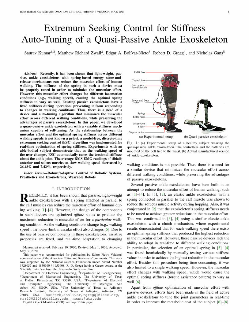
Fig. 1: (a) Experimental setup of a healthy subject wearing thequasi-passive ankle exoskeleton. The controllers and the batteries aremounted on the belt tied to the waist. (b) Actual manufactured versionof ankle exoskeleton.
walking conditions is not possible. Thus, there is a need fora similar device that minimizes the muscular effort acrossdifferent walking conditions, while preserving the advantagesof passive exoskeletons.
Several passive ankle exoskeletons have been built in anattempt to reduce the muscular effort of human walking, suchas [1]–[4]. In [1], [2], an elastic ankle exoskeleton with aspring connected in parallel to the calf muscle was shown toreduce the solueus muscle activity during hopping. Also, it wasconjectured in [2] that the exoskeleton’s spring stiffness needsto be tuned to achieve greater reductions in the muscular effort.This was confirmed in [3], [4] using a similar elastic ankleexoskeleton with a clutch mechanism, where experimentalresults demonstrated that for each walking speed there existsan optimal spring stiffness that produced the highest reductionin the muscular effort. However, these passive devices lack theability to adapt in real-time to different walking conditions.In particular, the selection of an optimal spring in [3], [4]was found heuristically by manually testing various stiffnessvalues in order to achieve the highest reduction in the musculareffort. Besides this procedure being time-consuming, it wasalso limited to a single walking speed. However, the musculareffort changes with walking speed, which would cause theoptimal spring stiffness (torque assistance pattern) to vary aswell [6].
Apart from offline optimization of muscular effort withpassive devices, efforts have been made in the field of activeankle exoskeletons to tune the joint parameters in real-timein order to improve the metabolic cost of the subject [6]–[8].
2 IEEE ROBOTICS AND AUTOMATION LETTERS. PREPRINT VERSION. MAY, 2020
However, using the metabolic cost as an objective functionleads to very slow adaptation that typically requires an hourto find a local optimum [9]. This slow process might not beapplicable for adapting to real-time changes in behavior orenvironment. In addition, the measurement of the metaboliccost requires off-board sensors, e.g., face masks, which mightbe obtrusive to the user. Also, most of the active exoskeletonsare restricted to the lab settings either due to the use of aheavy off-board motor [6], [10] or tethered air supply forpneumatically actuated exoskeletons [8], [11]–[13].
Quasi-passive exoskeletons combine the adaptability of ac-tive exoskeletons with the autonomy of passive exoskeletons.In particular, these devices have passive components likesprings [1], [2], dampers [14], [15] and also contains sensors,batteries and other electronics, but motors do not providepower directly to the human joint [16]. A quasi-passive legexoskeleton consisting of variable-damping mechanism at theknee joint was presented in [14], [15]. In this paper, wedeveloped a quasi-passive ankle exoskeleton that is able toadjust automatically through a range of torsional stiffnessabout the ankle joint via an adjustable lever-arm. Usingthis device, we conducted walking experiments at differentwalking speeds with the biological feedback provided by theelectromyography (EMG) sensors (see Fig. 1a). Due to theunknown underlying dynamics and noisy EMG measurements,we used a model-free extremum seeking control (ESC) toperform real-time tuning of torsional stiffness of the exoskele-ton in order to reduce the muscular effort of walking. TheESC uses a low-frequency perturbation signal to estimatethe gradient of the cost function, making it more robust tonoisy measurements [17]. Our experiments demonstrated thatESC was able to automatically tune the torsional stiffnessof the ankle exoskeleton across different walking speeds. Inparticular, there are two important contributions of this paper.Contributions of this paper
i) We built an unilateral quasi-passive ankle exoskeletonwith a variable stiffness mechanism. To the best ofour knowledge, this is the first quasi-passive devicecapable of real-time adaptation of stiffness in responseto muscular activity at varying walking conditions.
ii) In order to perform real-time optimization of the mus-cular effort, we implemented a model-free control al-gorithm, ESC, to automatically tune the stiffness of thesystem across different walking speeds. The advantageof using an ESC is that it does not need the knowledge ofthe underlying dynamics. Walking experiments demon-strate a noticeable reduction in the muscular effort usingour ESC algorithm. In addition, ESC adapts the stiffnessof the system within 10 seconds as the walking speedschange.
The paper is organized as follows. In Section II, wedescribe the mechatronic design of the quasi-passive ankleexoskeleton and the discrete-time ESC algorithm for real-time stiffness tuning of the exoskeleton. In Section III, wedescribe the experimental setup and protocol followed forwalking experiments. Next, we present the baseline and ESCexperimental results in Section IV. We discuss these results
Stepper Motor
Force Sensitive Resistors
Slider
Spring
Calf Strap
Footbed
Lever-arm
Vertical shanksupport
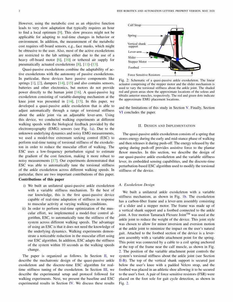
Fig. 2: Schematic of a quasi-passive ankle exoskeleton. The linearactuator comprising of the stepper motor and the slider mechanism isused to vary the torsional stiffness about the ankle joint. The shadedred and green areas show the approximate locations of the soleus andtibialis anterior muscles, respectively. The red and green dots indicatethe approximate EMG placement locations.
and the limitations of this study in Section V. Finally, SectionVI concludes the paper.
II. DESIGN AND IMPLEMENTATION
The quasi-passive ankle exoskeleton consists of a spring thatstores energy during the early and mid-stance phase of walkingand then releases it during push-off. The energy released by thespring during push-off provides assistive force to the plantarflexor muscles. In this section, we describe the design ofour quasi-passive ankle exoskeleton and the variable stiffnesslever, its embedded sensing capabilities, and the discrete-timeperturbation-based ESC algorithm used to modify the torsionalstiffness of the device.
A. Exoskeleton Design
We built a unilateral ankle exoskeleton with a variablestiffness mechanism, as shown in Fig. 1b. The exoskeletonhas a carbon-fiber frame and a lever-arm assembly consistingof a slider and a stepper motor. The frame was made up ofa vertical shank support and a footbed connected to the anklejoint. A free motion Tamarack Flexure JointTM was used at theankle joint to reduce the weight of the device. This joint stylewas chosen to allow for minor inversion and eversion motionat the ankle joint to minimize the impact on the user’s naturalgait. Attached to the footbed section of the device is a lever-arm assembly with a variable attachment point for the spring.This point was connected by a cable to a coil spring anchoredat the top of the frame near the calf muscle, as shown in Fig.2. The position of the variable attachment point controls thesystem’s torsional stiffness about the ankle joint (see SectionII-B). The top of the vertical shank support is secured justbelow the user’s knee with a padded Velcro strap, and thefootbed was placed in an athletic shoe allowing it to be securedto the user’s foot. A pair of force sensitive resistors (FSR) wereplaced on the foot sole for gait cycle detection, as shown inFig. 2.

KUMAR et al.: EXTREMUM SEEKING CONTROL FOR STIFFNESS AUTO-TUNING OF A QUASI-PASSIVE ANKLE EXOSKELETON 3
Stepper Motor Sliding mount Ball screw
Bearings Slider track
Fig. 3: Bottom view of the variable stiffness lever-arm.
B. Variable Stiffness Lever Design
In order to vary the torsional stiffness about the ankle jointin our exoskeleton, we built a lever-arm to have a variable-effective length, as shown in Fig. 3. The lever-arm designconsists of a MiSUMiTM ball screw assembly mounted ina rigid frame. A slider attached to the ball nut includesan attachment point for the spring and bilateral wings totransfer force generated by the spring to the frame, preventingradial loading of the ball screw. The ball screw has a leadof 2 mm and is powered by a QMot QSH2818 TrinamicMotion ControlTM stepper motor with 200 steps/rev. The linearactuator comprising the ball screw and the stepper motor hasa travel of 0.085 m, allowing the lever-arm to vary from 0.17m to 0.25 m, with 8500 discrete positions. Assuming smallangle variation between the spring and the slider track acrossall slider positions, the torsional stiffness about the ankle jointis the product of the spring force F and the effective lever-armlength at any given slider position L. The spring force F isgiven by
F = ksx (1)
where x is the displacement of the spring’s length, whichscales with the effective length of the lever-arm L, and ksis the stiffness constant of the spring in N/m. The calculationfor the system’s torsional stiffness simplifies to [18]
kexo = ksL2, (2)
where kexo is the torsional stiffness of the exoskeleton aboutthe ankle joint in Nm/rad. Thus, changing the lever-arm lengthfrom 0.17-0.25 m modifies the stiffness from 1-2.25 times theminimum torsional stiffness. For instance, we used a springof 5.8 kN/m to implement a torsional stiffness range of 169-362 Nm/rad. This spring stiffness was chosen such that theoptimum torsional stiffness as found in [3] lies in the aboverange. The total mass of the exoskeleton frame including thevariable stiffness lever was 1323 g.Remark 1: The stepper motor in our variable stiffness mech-anism varies only the torsional joint stiffness and does notprovide power to the joint, which allows us to select a smalllow-power motor. For designs that power the ankle jointdirectly, we recommend the reader to review the state-of-artvariable stiffness actuators such as the MACCEPA [19], [20].
Note that powering the ankle joint directly requires heavieractuators than our proposed mechanism.
C. Embedded Systems and Sensing
All sensing, data recording, ESC implementation (detailedin Section II-D) and motor controls were performed on-boardusing an Arduino Mega 2560 microcontroller. The musculareffort of the soleus and tibialis anterior muscles were measuredby two MyowareTM EMG sensors (AT-04-001). The Myowaresensor provided on-board amplification, rectification, and in-tegration, which was utilized to reduce processing demand onthe system’s controller. To protect the raw EMG signal frominterference, all wires carrying unamplified EMG signals weredouble shielded. The stepper motors were powered by two2300 mAh 12V nickel metal hydride batteries connected inseries to provide 24 V with a total battery capacity of 55.2 W-h. All the components above were secured to a padded belt,which was worn at the user’s waist, as shown in Fig. 1a. Thetotal weight of the belt containing all of the components andthe batteries was 1750 g. Data and power cables were runlaterally down the user’s leg, connecting the controller to thesensors and motors.
D. Discrete ESC for Stepper Motors
ESC is a model-free adaptive control method that finds anoptimum set-point in order to minimize/maximize an objectivefunction, whose analytical expression might be unknown [9],[21]–[23]. Fig. 4 shows a block diagram of a discrete-timeESC with a human-in-the-loop. We modified the structure ofconventional discrete-time ESC [24] by observing that thestepper motor dynamics already have an integrator [25]. Inparticular, we moved the ESC integrator in the conventionalESC structure ahead of the summer block. In this modifiedstructure, the ESC integration is performed by the motordynamics itself.
In order to understand the benefit of this ESC structurefor implementation with a stepper motor, we first brieflyexplain the stepper motor operation. A stepper motor runs ona pulsed current, where each pulse turns the motor a fractionof the full rotation. It does not have any closed-loop encoderfeedback for position control. Instead it accepts a change inthe motor location as an input command instead of the finalmotor location. The purpose of modifying the structure ofconventional discrete-time ESC in [24] was specifically doneto satisfy this requirement of stepper motors.Remark 2: The modified structure of ESC algorithm is adiscretized version of ESC presented in [26]–[28] and ismore suitable for implementation with stepper motor than theconventional ESC structure for the reasons stated above. Theconventional ESC structure would have commanded the finalmotor location, whereas our modified structure commands achange in the motor location.
The working of the discrete-time ESC can be explained asfollows. The ESC algorithm adds a small periodic perturbationsignal d1(k) = −aω sin(ωk), known as the dither signal, tothe commanded change in the motor location ∆θ(k). Assume

4 IEEE ROBOTICS AND AUTOMATION LETTERS. PREPRINT VERSION. MAY, 2020
EMG
Stepper Motor
Muscular Effort
High-pass �ilter
Fig. 4: Block diagram of a perturbation-based discrete ESC witha human-in-the-loop. The ESC commands a change in the steppermotor location ∆θ(k), which moves the spring set-point in the lever-arm. With the new effective lever-arm length, the user walks and theEMG readings are measured to quantify the objective function J(·).
that the stepper motor dynamics is modeled as a cascade con-nection of a zero-order hold and a continuous-time integrator.The zero-order hold circuit holds the sample ∆θ(k) + d1(k)constant for one sampling interval ∆T . Denoting tk as thesampling time, the expression for θ(tk) can be written asθ(tk) ≈ ∆θ(k)/∆T−aω sin(ωtk). The integrator dynamics ofthe stepper motor then outputs θ(tk)+a cos(ωtk), where θ(tk)is the position of the stepper motor at time tk. The objectivefunction J(·) (e.g., muscular effort) measured at this motorposition is sampled to give J(θ(k) + a cos(ωk)). The Taylorseries approximation of J(θ(k)+a cos(ωk)) can be written as
J(·)≈J(θ(k))+J ′(θ(k))a cos(ωk)+J ′′(θ(k))
2a2 cos2(ωk)
=J(θ(k))+J ′(θ(k))a cos(ωk)+a2J ′′(θ(k))
4(1+ cos 2(ωk)),
(3)
where J ′, J ′′ are the first and the second derivatives of J(·)with respect to θ. The objective function measurements in (3)are passed through a high-pass filter (HPF), which removesthe DC components J(θ(k)) and a2J ′′(θ(k))/4 to give
ξ(k) = J ′(θ(k))a cos(ωk) +a2J ′′(θ(k))
4cos(2ωk). (4)
The output of the HPF ξ(k) is then multiplied by anotherdither signal a cos(ωk) and scaled by a gain −γ to generate
∆θ(k)=-γ[J ′(·)a cos(ωk)+
a2J ′′(·)4
cos(2ωk)]a cos(ωk)
=-γ[a2J ′(·)
2[1+ cos(2ωk)]+
a3J ′′(·)4
cos(2ωk) cos(ωk)], (5)
which indicates the amount that the motor should move inorder to minimize the cost function. From (5), it can be seenthat ∆θ(k) consists of a DC component, which is proportionalto J ′(·), and contains other higher frequency terms. Followingstandard manipulations (see [24]), the update equations ofdiscrete-time ESC can be written as
ξ(k) = −hξ(k − 1) + J(θ(k))− J(θ(k − 1)) (6)∆θ(k) = −γ[ξ(k)a cos(ωk)] (7)
where γ is the adaptation gain and h ∈ (0, 1) is the HPF cut-off frequency. The stability of the algorithm can be provedbased on two-time scale averaging theory (see [24] for furtherdetails).
E. ESC Code Implementation
The code for the ESC controlled system runs in 3 nestedloops: the ESC loop, the aggregation loop, and the gait detec-tion loop. The gait detection loop is the innermost loop, whoseprimary function is to read all sensors and record data as wellas detect each gait cycle using the 2 FSRs. In each iterationof this loop, the rectified EMG readings from both the tibialisanterior and soleus muscles were summed and then integratedover a gait cycle using a rectangular integration method witha step size of 0.033 seconds. Once a gait cycle is detected,the aggregation loop adds the area for the step that was justdetected to an aggregated area value. This process continuesuntil 3 gait cycles are detected. The aggregated area value,containing the total integrated EMG area for the previous 3gait cycles, is then used as an objective function input to theESC algorithm. We chose 3 gait cycles for computing theobjective function to achieve a balance between the robustnessand the convergence rate of ESC adaptation. A pseudo codefor the ESC operational loop is available for download in thesupplementary materials.Remark 3: The integration that occurs in the gait detectionloop converts the instantaneous EMG signals into a meaning-ful value that quantifies the total muscular effort of each step.The aggregation loop acts as a filter on the inherent noise ofthe biological signal by combining multiple steps.
III. EXPERIMENTAL SETUP AND PROTOCOL
A. Experimental Setup
The experiment protocol was approved by the InstitutionalReview Board (IRB) at the University of Texas at Dallas.Experiments were conducted with a healthy subject wearingthe ankle exoskeleton while walking on a treadmill. Two EMGsensors were placed on the soleus and the tibialis anteriormuscles after skin preparation to measure the muscular effortat 30 Hz. In order to normalize the EMG readings, a maximumvoluntary contraction (MVC) experiment was first conducted,in which the user was instructed to flex each muscle ashard as possible. The skin preparation, sensor placement, andthe MVC experimental procedures followed the guidelinessuggested in [29]. This MVC experiment was conducted justonce prior to the start of sweep and ESC experiments (seeSection IV-A, IV-B).
Prior to testing, the subject was fitted with an ankle ex-oskeleton and given a chance to acclimate to it, while theelectrical control was disabled. During the acclimation period,the torsional stiffness of the exoskeleton was fixed at a medianvalue of 194 Nm/rad. After acclimation, the subject wasinstructed to walk on the treadmill at 1.0 m/s and 1.5 m/s forup to 5 minutes for baseline walking experiments (see SectionIV-A) and up to 15 minutes for ESC walking experiments(see Section IV-B), whose protocols are discussed next. Allexperiments were done on level ground on the same day, and

KUMAR et al.: EXTREMUM SEEKING CONTROL FOR STIFFNESS AUTO-TUNING OF A QUASI-PASSIVE ANKLE EXOSKELETON 5
the user was given sufficient rest in between the experimentsto avoid fatigue.
B. Experiment Protocol for Baseline Walking Experiments
Following acclimation, the user was asked to walk on atreadmill at 1 m/s until 30 gait cycles of data had beencollected. At that point the slider would advance to the nextequally spaced slider position and another 30 gait cycles ofdata were recorded. This process continued until 5 equallyspaced positions had been tested from one end of the lever-arm to the other end. In this manner, the user’s musculareffort response to the full range of torsional stiffness wastested. This process lasted for approximately 5 minutes, witha total of 150 gait cycles being recorded. Steps taken duringslider adjustment were removed from the data set and werenot included in the above mentioned step count. Due tothe variation in the gait patterns, the muscular effort duringeach step was different. Therefore, we conducted 6 baselinewalking trials, giving 180 steps of data for each slider location.Following this, the same protocol was repeated for fast walkingspeed (1.5 m/s).
C. Experiment Protocol for ESC Walking Experiments
After baseline testing, the user walked on a treadmill for15 minutes per experiment. Two versions of this experimentwere performed —slow-fast-slow (SFS) and fast-slow-fast(FSF). For SFS testing, the user was instructed to walk at1 m/s for 5 minutes. At the 5 minute point, the treadmillspeed was increased to 1.5 m/s, which was maintained foranother 5 minutes. At the 10 minute point, the treadmill speedwas reduced back to 1 m/s and held for another 5 minutes.Similarly, the FSF case started and ended at 1.5 m/s, with thesame time intervals for the three speed conditions.
IV. EXPERIMENTAL TESTING RESULTS
A. Baseline Walking Experiments
There were two main goals for performing baseline walkingtrials. First, we wanted to demonstrate that a change in theslider location affects the muscular effort during walking.Second, as the optimum slider location for different walkingspeeds was not known a priori, we wanted to experimentallydetermine the optimum slider location for this subject atdifferent walking speeds. This information helps us validatethe real-time ESC adaptation results across different walkingspeeds in Section IV-B.
In order to show the effect of slider location on the musculareffort, we grouped the EMG readings from all experiments byslider locations. This resulted in 180 sample data points perslider location (i.e., 30 samples/test × 6 tests). A control testwas also performed with no spring (NS). Figs. 5a, 5b showbox plots obtained from 6 baseline and NS tests for slow andfast walking speeds, respectively. Two important observationscan be made from this result: (i) By comparing Figs. 5a, 5b itcan be noted that the optimum slider location for slow walkingspeed (L=25 cm at 1 m/s) is higher than that for fast walkingspeed (L=17 cm at 1.5 m/s); and (ii) Due to the variations in
NS 17 19 21 23 25
2.5
3.5
4.5
5.5
6.5
7.5
8.5
(a) Baseline walking experiment result at slow walking speed (1 m/s),indicating the minimum median muscle effort at lever-arm lengthL=25 cm.
NS 17 19 21 23 25
2.5
3.5
4.5
5.5
6.5
7.5
8.5
(b) Baseline walking experiment result at fast walking speed (1.5m/s), indicating the minimum median muscle effort at lever-armlength L=17 cm.
Fig. 5: Box plot of baseline and no spring (NS) tests at differentwalking speeds. The x-axis indicates the lever-arm length L, withL=17 cm and L=25 cm being closest and farthest from the anklejoint, respectively. It can be seen that the EMG readings are higherat fast walking speed as compared to slow walking speed. It can alsobe seen that each walking speed has a different optimum lever-armlength that minimizes the median muscular effort, thus necessitatingthe need for real-time adaptation with changes in walking speed.
the gait pattern, there are multiple local optimums. Note thatdue to the complex landscape of the objective function, ourESC algorithm would only be able to tune the system to alocal minimum.
Next, we ran Lilliefors test for normality and found that theEMG data at each slider location was not normally distributed.In such a case, a non-parametric test, such as Friedman,Kolmogorov–Smirnov, Wilcoxon signed-rank, should be per-formed [30]. We first conducted a Friedman’s test to checkthe validity of the null hypothesis that all samples taken atdifferent slider locations come from the same distribution. TheFriedman’s test, performed in MATLAB, returned a p−valueof 7.4×10⁻⁹ for slow and 2.6×10⁻¹⁴ for fast walking speeds,which is much less than the significant threshold of 0.05. Thisimplies that we can reject the null hypothesis and concludethat a change in slider location makes a difference in themuscular effort for this subject. Next, we conducted Wilcoxon

6 IEEE ROBOTICS AND AUTOMATION LETTERS. PREPRINT VERSION. MAY, 2020
TABLE I: Pairwise Wilcoxon signed-rank test results betweendifferent slider locations L at slow and fast speed.
(a) p-values from Wilcoxon signed-rank test at slow speed.
L (cm)Lever-arm length L (cm)
17 19 21 23 25
17 1.0000 0.6011 0.3118 0.0028∗ 0.0001∗19 0.6011 1.0000 0.7135 0.0021∗ 0.0000∗21 0.3118 0.7135 1.0000 0.0000∗ 0.0000∗23 0.0028∗ 0.0021∗ 0.0000∗ 1.0000 0.213125 0.0001∗ 0.0000∗ 0.0000∗ 0.2131 1.0000
(b) p-values from Wilcoxon signed-rank test at fast speed.
L (cm)Lever-arm length L (cm)
17 19 21 23 25
17 1.0000 0.0000∗ 0.0000∗ 0.0000∗ 0.0002∗19 0.0000∗ 1.0000 0.0001∗ 0.0258 0.0000∗21 0.0000∗ 0.0001∗ 1.0000 0.3870 0.0008∗23 0.0000∗ 0.0258 0.3870 1.0000 0.0000∗25 0.0002∗ 0.0000∗ 0.0008∗ 0.0000∗ 1.0000
signed-rank statistical tests for EMG data collected at eachpair of slider locations. We chose Wilcoxon signed-rankover other non-parametric tests because it performs pairedhypothesis testing and assumes dependent data samples. Inour case, a paired hypothesis testing is suitable because thesame muscle readings are recorded multiple times at differentslider locations. Also, since the EMG readings for this subjectcome from the same muscles, the EMG data at different sliderlocations are dependent. We formulated a null hypothesis thatthe median difference between the EMG data at differentslider locations (excluding NS) is zero. The p values for allcombinations of slider locations at different walking speeds aretabulated in Table I. An asterisk at the end of p-value indicatesstatistical significance between the pair of slider locations.Tables Ia and Ib show that the effect of the slider locationon the muscular effort varies across walking speed.
To avoid false reporting of significant differences in mul-tiple pairwise comparisons, we use the Bonferroni-correctedthreshold value of 0.005. For slow walking speed, it can beseen from Table Ia that there are 2 groups of slider locationsthat result in statistically different EMG data for this subject,based on a threshold of p = 0.005. One group comprises sliderlocations L=17, 19 and, 21 cm, and the other group comprisesslider locations L=23 and 25 cm. Similarly, for fast walkingspeed, we see from Table Ib that the EMG data at all sliderlocations (except between L=19 and 23 cm and L=21 and 23cm) are statistically different for this subject.Remark 4: Figs. 5a, 5b show that the EMG readings arehigher for no spring as compared to with spring for both slowand fast walking speeds, thus clearly indicating the benefit ofusing the spring in the device.
B. ESC Walking Experiments
Fig. 6 shows the ESC adaptation results for the two differentexperimental scenarios discussed in Section III. The ESCparameters selected were a = 2, γ = −10, ω = 0.55Hz, h =0.5Hz, according to the guidelines mentioned in [9]. Because
0 20 40 60 80 100 12010
15
20
25
21
21.5
22
22.5
23
23.5
24
(a) Slow-Fast-Slow ESC experiment
0 20 40 60 80 100 120 14010
12
14
16
18
20
22
21
21.5
22
22.5
23
23.5
24
(b) Fast-Slow-Fast ESC experiment
Fig. 6: Real-time ESC adaptation of lever-arm length (torsionalstiffness) across different walking speeds. The blue dots are theaccumulated EMG area for 3 gait cycles (one ESC iteration), andthe red dots are the lever-arm lengths at a particular ESC iteration.The solid blue and red lines are fitted by smoothing the data usinglocally weighted linear regression. The vertical black dashed linesindicate the ESC iteration at which the walking speed was changed.It can be seen that ESC quickly adapts the lever-arm position inresponse to change in muscular effort at walking speed transitions.
the walking speed was changed based on time (after every 5minutes), the fast walking regime has more ESC iterations ascompared to the slow walking. In the slow regimes (first andthird regime of Fig. 6a and second regime of Fig. 6b), we seethat the lever-arm length increases and eventually approachesa steady-state, which in turn reduces the muscle effort. This isexactly in accordance with the baseline walking experimentalresults in Section IV-A. Next, at the speed transitions, we seea sudden change in the muscle effort followed by a rapidESC adaptation of the lever-arm length in the direction weexpect. At fast speed regimes (second regime of Fig. 6a andfirst and third regime of Fig. 6b), we see the lever-arm lengthdecreasing as we expect. However, we do not see a dramaticreduction in the muscle effort, which we explore more inSection V.
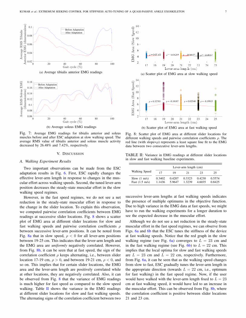
Fig. 7 shows the average EMG readings for tibialis anteriorand soleus muscles at slow walking speed. The blue andred lines represent the average of EMG readings across gaitcycles during the first and the last minute of slow speedwalking, respectively. It can be noted that the average EMGreadings for both of the tibialis anterior and soleus musclesdecreased significantly after ESC adaptation. In particular, theaverage RMS EMG readings of tibialis anterior and soleusmuscles decreased by 26.48% and 7.42%, respectively. From(2), we see that changing the lever-arm length from L=23 cmto L=22 cm decreases the torsional stiffness kexo by 9.3%.
A supplemental video of the experiment is available fordownload.
KUMAR et al.: EXTREMUM SEEKING CONTROL FOR STIFFNESS AUTO-TUNING OF A QUASI-PASSIVE ANKLE EXOSKELETON 7
0 20 40 60 80 1000.02
0.04
0.06
0.08
0.1Before Adaptation
After Adaptation
(a) Average tibialis anterior EMG readings
0 20 40 60 80 1000.06
0.08
0.1
0.12
0.14
0.16
0.18Before Adaptation
After Adaptation
(b) Average soleus EMG readings
Fig. 7: Average EMG readings for tibialis anterior and soleusmuscles before and after ESC adaptation at slow walking speed. Theaverage RMS value of tibialis anterior and soleus muscle activitydecreased by 26.48% and 7.42%, respectively.
V. DISCUSSION
A. Walking Experiment Results
Two important observations can be made from the ESCadaptation results in Fig. 6. First, ESC rapidly changes theeffective lever-arm length in response to changes in the mus-cular effort across walking speeds. Second, the tuned lever-armposition decreases the steady-state muscular effort in the slowwalking speed regimes.
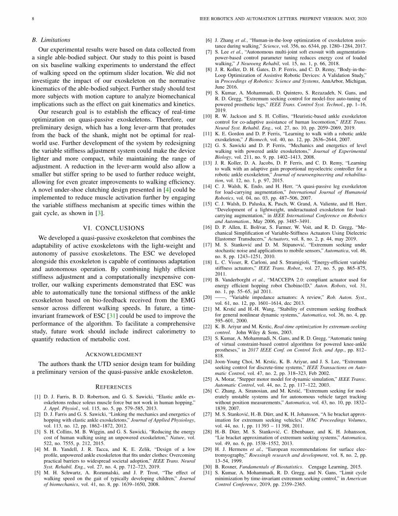
However, in the fast speed regimes, we do not see a netreduction in the steady-state muscular effort in response tothe change in the slider location. To explain this observation,we computed pairwise correlation coefficients between EMGreadings at successive slider locations. Fig. 8 shows a scatterplot of EMG area at different slider locations for slow andfast walking speeds and pairwise correlation coefficients ρbetween successive lever-arm positions. It can be noted fromFig. 8a that in slow speed, ρ < 0 for all lever-arm positionsbetween 19-25 cm. This indicates that the lever-arm length andthe EMG area are uniformly negatively correlated. However,from Fig. 8b, it can be seen that at fast speed, the sign of thecorrelation coefficient ρ keeps alternating, i.e., between sliderlocation 17-19 cm, ρ > 0, and between 19-21 cm, ρ < 0, andso on. This implies that for certain slider locations, the EMGarea and the lever-arm length are positively correlated whileat other locations, they are negatively correlated. Also, it canbe observed from Fig. 8 that the variance of EMG readingsis much higher for fast speed as compared to the slow speedwalking. Table II shows the variance in the EMG readingsat different slider locations for slow and fast walking speeds.The alternating signs of the correlation coefficient between two
(a) Scatter plot of EMG area at slow walking speed
17 18 19 20 21 22 23 24 25
2
4
6
8
10
12
14
= 0.32793 = -0.18187 = 0.02540 = -0.19915
(b) Scatter plot of EMG area at fast walking speed
Fig. 8: Scatter plot of EMG area at different slider locations fordifferent walking speeds and pairwise correlation coefficients ρ. Thered line (with slope=ρ) represents a least square line fit to the EMGdata between two consecutive lever-arm lengths.
TABLE II: Variance in EMG readings at different slider locationsin slow and fast walking baseline experiments.
Walking SpeedLever-arm length (cm)
17 19 21 23 25
Slow (1 m/s) 0.3402 0.4207 0.3323 0.4230 0.5574Fast (1.5 m/s) 1.1436 5.9647 1.3239 4.6035 0.8425
successive lever-arm lengths at fast walking speeds indicatesthe presence of multiple optimums in the objective function.Due to high variance in the EMG data at fast speeds, we mighthave to run the walking experiments for a longer duration tosee the expected decrease in the muscular effort.
Although we do not see a net reduction in the steady-statemuscular effort in the fast speed regimes, we can observe fromFigs. 6a and 6b that the ESC tunes the stiffness of the deviceat fast walking speeds. Notice that the red graph in the slowwalking regime (see Fig. 6a) converges to L = 23 cm andin the fast walking regime (see Fig. 6b) to L = 22 cm. Thisimplies that the local optima for slow and fast walking speedsare L = 23 cm and L = 22 cm, respectively. Furthermore,from Fig. 6a, it can be seen that as the walking speed changesfrom slow to fast, ESC gradually tunes the lever-arm length inthe appropriate direction (towards L = 22 cm, i.e., optimumfor fast walking) in the fast speed regime. Now, if the userwould have walked with the lever-arm length fixed to L = 23cm at fast walking speed, it would have led to an increase inthe muscular effort. This can be observed from Fig. 8b, wherethe correlation coefficient is positive between slider locations21 and 23 cm.
8 IEEE ROBOTICS AND AUTOMATION LETTERS. PREPRINT VERSION. MAY, 2020
B. Limitations
Our experimental results were based on data collected froma single able-bodied subject. Our study to this point is basedon six baseline walking experiments to understand the effectof walking speed on the optimum slider location. We did notinvestigate the impact of our exoskeleton on the normativekinematics of the able-bodied subject. Further study should testmore subjects with motion capture to analyze biomechanicalimplications such as the effect on gait kinematics and kinetics.
Our research goal is to establish the efficacy of real-timeoptimization on quasi-passive exoskeletons. Therefore, ourpreliminary design, which has a long lever-arm that protudesfrom the back of the shank, might not be optimal for real-world use. Further development of the system by redesigningthe variable stiffness adjustment system could make the devicelighter and more compact, while maintaining the range ofadjustment. A reduction in the lever-arm would also allow asmaller but stiffer spring to be used to further reduce weight,allowing for even greater improvements to walking efficiency.A novel under-shoe clutching design presented in [4] could beimplemented to reduce muscle activation further by engagingthe variable stiffness mechanism at specific times within thegait cycle, as shown in [3].
VI. CONCLUSIONSWe developed a quasi-passive exoskeleton that combines the
adaptability of active exoskeletons with the light-weight andautonomy of passive exoskeletons. The ESC we developedalongside this exoskeleton is capable of continuous adaptationand autonomous operation. By combining highly efficientstiffness adjustment and a computationally inexpensive con-troller, our walking experiments demonstrated that ESC wasable to automatically tune the torsional stiffness of the ankleexoskeleton based on bio-feedback received from the EMGsensor across different walking speeds. In future, a time-invariant framework of ESC [31] could be used to improve theperformance of the algorithm. To facilitate a comprehensivestudy, future work should include indirect calorimetry toquantify reduction of metabolic cost.
ACKNOWLEDGMENT
The authors thank the UTD senior design team for buildinga preliminary version of the quasi-passive ankle exoskeleton.
REFERENCES
[1] D. J. Farris, B. D. Robertson, and G. S. Sawicki, “Elastic ankle ex-oskeletons reduce soleus muscle force but not work in human hopping,”J. Appl. Physiol., vol. 115, no. 5, pp. 579–585, 2013.
[2] D. J. Farris and G. S. Sawicki, “Linking the mechanics and energetics ofhopping with elastic ankle exoskeletons,” Journal of Applied Physiology,vol. 113, no. 12, pp. 1862–1872, 2012.
[3] S. H. Collins, M. B. Wiggin, and G. S. Sawicki, “Reducing the energycost of human walking using an unpowered exoskeleton,” Nature, vol.522, no. 7555, p. 212, 2015.
[4] M. B. Yandell, J. R. Tacca, and K. E. Zelik, “Design of a lowprofile, unpowered ankle exoskeleton that fits under clothes: Overcomingpractical barriers to widespread societal adoption,” IEEE Trans. NeuralSyst. Rehabil. Eng., vol. 27, no. 4, pp. 712–723, 2019.
[5] M. H. Schwartz, A. Rozumalski, and J. P. Trost, “The effect ofwalking speed on the gait of typically developing children,” Journalof biomechanics, vol. 41, no. 8, pp. 1639–1650, 2008.
[6] J. Zhang et al., “Human-in-the-loop optimization of exoskeleton assis-tance during walking,” Science, vol. 356, no. 6344, pp. 1280–1284, 2017.
[7] S. Lee et al., “Autonomous multi-joint soft exosuit with augmentation-power-based control parameter tuning reduces energy cost of loadedwalking,” J Neuroeng Rehabil, vol. 15, no. 1, p. 66, 2018.
[8] J. R. Koller, D. H. Gates, D. P. Ferris, and C. D. Remy, “Body-in-the-Loop Optimization of Assistive Robotic Devices: A Validation Study,”in Proceedings of Robotics: Science and Systems, AnnArbor, Michigan,June 2016.
[9] S. Kumar, A. Mohammadi, D. Quintero, S. Rezazadeh, N. Gans, andR. D. Gregg, “Extremum seeking control for model-free auto-tuning ofpowered prosthetic legs,” IEEE Trans. Control Syst. Technol., pp. 1–16,2019.
[10] R. W. Jackson and S. H. Collins, “Heuristic-based ankle exoskeletoncontrol for co-adaptive assistance of human locomotion,” IEEE Trans.Neural Syst. Rehabil. Eng., vol. 27, no. 10, pp. 2059–2069, 2019.
[11] K. E. Gordon and D. P. Ferris, “Learning to walk with a robotic ankleexoskeleton,” J Biomech, vol. 40, no. 12, pp. 2636–2644, 2007.
[12] G. S. Sawicki and D. P. Ferris, “Mechanics and energetics of levelwalking with powered ankle exoskeletons,” Journal of ExperimentalBiology, vol. 211, no. 9, pp. 1402–1413, 2008.
[13] J. R. Koller, D. A. Jacobs, D. P. Ferris, and C. D. Remy, “Learningto walk with an adaptive gain proportional myoelectric controller for arobotic ankle exoskeleton,” Journal of neuroengineering and rehabilita-tion, vol. 12, no. 1, p. 97, 2015.
[14] C. J. Walsh, K. Endo, and H. Herr, “A quasi-passive leg exoskeletonfor load-carrying augmentation,” International Journal of HumanoidRobotics, vol. 04, no. 03, pp. 487–506, 2007.
[15] C. J. Walsh, D. Paluska, K. Pasch, W. Grand, A. Valiente, and H. Herr,“Development of a lightweight, underactuated exoskeleton for load-carrying augmentation,” in IEEE International Conference on Roboticsand Automation., May 2006, pp. 3485–3491.
[16] D. P. Allen, E. Bolıvar, S. Farmer, W. Voit, and R. D. Gregg, “Me-chanical Simplification of Variable-Stiffness Actuators Using DielectricElastomer Transducers,” Actuators, vol. 8, no. 2, p. 44, may 2019.
[17] M. S. Stankovic and D. M. Stipanovic, “Extremum seeking understochastic noise and applications to mobile sensors,” Automatica, vol. 46,no. 8, pp. 1243–1251, 2010.
[18] L. C. Visser, R. Carloni, and S. Stramigioli, “Energy-efficient variablestiffness actuators,” IEEE Trans. Robot., vol. 27, no. 5, pp. 865–875,2011.
[19] B. Vanderborght et al., “MACCEPA 2.0: compliant actuator used forenergy efficient hopping robot Chobino1D,” Auton. Robots, vol. 31,no. 1, pp. 55–65, jul 2011.
[20] ——, “Variable impedance actuators: A review,” Rob. Auton. Syst.,vol. 61, no. 12, pp. 1601–1614, dec 2013.
[21] M. Krstic and H.-H. Wang, “Stability of extremum seeking feedbackfor general nonlinear dynamic systems,” Automatica, vol. 36, no. 4, pp.595–601, 2000.
[22] K. B. Ariyur and M. Krstic, Real-time optimization by extremum-seekingcontrol. John Wiley & Sons, 2003.
[23] S. Kumar, A. Mohammadi, N. Gans, and R. D. Gregg, “Automatic tuningof virtual constraint-based control algorithms for powered knee-ankleprostheses,” in 2017 IEEE Conf. on Control Tech. and App., pp. 812–818.
[24] Joon-Young Choi, M. Krstic, K. B. Ariyur, and J. S. Lee, “Extremumseeking control for discrete-time systems,” IEEE Transactions on Auto-matic Control, vol. 47, no. 2, pp. 318–323, Feb 2002.
[25] A. Morar, “Stepper motor model for dynamic simulation,” IEEE Transc.Automatic Control, vol. 44, no. 2, pp. 117–122, 2003.
[26] C. Zhang, A. Siranosian, and M. Krstic, “Extremum seeking for mod-erately unstable systems and for autonomous vehicle target trackingwithout position measurements,” Automatica, vol. 43, no. 10, pp. 1832–1839, 2007.
[27] M. S. Stankovic, H.-B. Durr, and K. H. Johansson, “A lie bracket approx-imation for extremum seeking vehicles,” IFAC Proceedings Volumes,vol. 44, no. 1, pp. 11 393 – 11 398, 2011.
[28] H.-B. Durr, M. S. Stankovic, C. Ebenbauer, and K. H. Johansson,“Lie bracket approximation of extremum seeking systems,” Automatica,vol. 49, no. 6, pp. 1538–1552, 2013.
[29] H. J. Hermens et al., “European recommendations for surface elec-tromyography,” Roessingh research and development, vol. 8, no. 2, pp.13–54, 1999.
[30] B. Rosner, Fundamentals of Biostatistics. Cengage Learning, 2015.[31] S. Kumar, A. Mohammadi, R. D. Gregg, and N. Gans, “Limit cycle
minimization by time-invariant extremum seeking control,” in AmericanControl Conference, 2019, pp. 2359–2365.