Extreme Environments Test Capabilities at NASA … · Extreme Environments Test Capabilities at...
34
National Aeronautics and Space Administration www.nasa.gov Extreme Environments Test Capabilities at NASA GRC for Parker Hannifin Visit June 8, 2016 Lori Arnett https://ntrs.nasa.gov/search.jsp?R=20170004840 2018-08-31T09:46:36+00:00Z
-
Upload
phungthien -
Category
Documents
-
view
218 -
download
0
Transcript of Extreme Environments Test Capabilities at NASA … · Extreme Environments Test Capabilities at...

National Aeronautics and Space Administration
www.nasa.gov
Extreme Environments Test Capabilities at NASA GRC
for Parker Hannifin Visit
June 8, 2016Lori Arnett
https://ntrs.nasa.gov/search.jsp?R=20170004840 2018-08-31T09:46:36+00:00Z

National Aeronautics and Space Administration
www.nasa.gov
Relevant Test Facilities
• Fuel Cell Testing Lab• Structural Dynamics Lab• Thermal Vacuum Test Facilities• EMI Test Lab• Creek Road Cryogenic Complex
National Aeronautics and Space Administration
www.nasa.gov 3
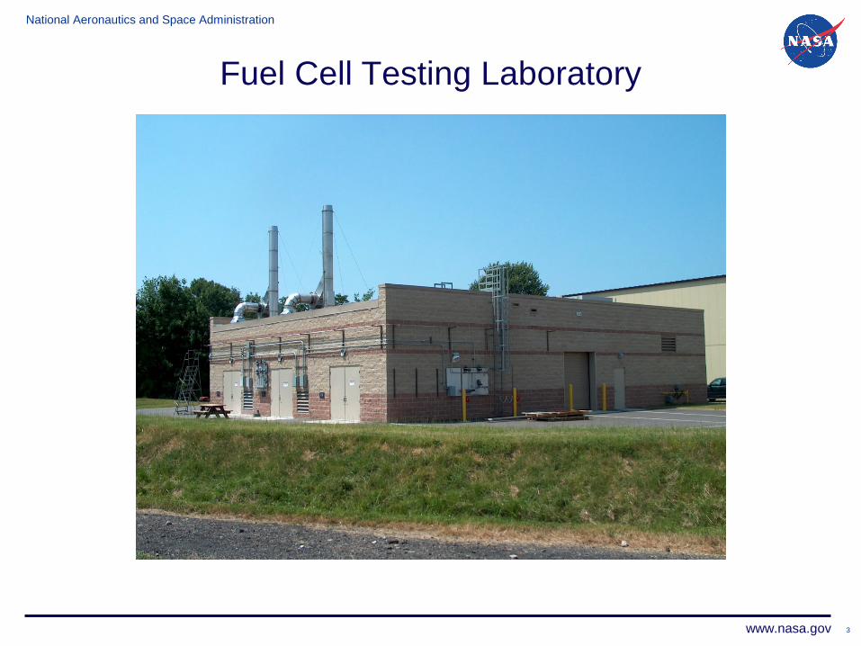
Fuel Cell Testing Laboratory

National Aeronautics and Space Administration
www.nasa.gov 4
Fuel Cell Testing Laboratory• Test Cell 111 dedicated for fuel cell testing
– Test capability for fuel cells at stack level through full system withbalance of plant
– Test Cell is designed for a variety of sizes and types of Fuel Cells• Can run FC’s ranging from 1 kW up to 125 kW• Can run hydrogen/air Fuel Cells• Can run hydrogen/oxygen Fuel Cells• Other supply gases possible depending on demand
– Test Cell has built in Safety Devices & Control• Combustible Gas (hydrogen) detectors, 2• High/Low O2 sensor• Heat Detection Cable (190 degrees F)• Tied into Dispatch which notifies first responders• Class 1, Division 2, Group B NEC rating• Cell operates via PLC, unattended operations allowable

National Aeronautics and Space Administration
www.nasa.gov 5
Fuel Cell Testing Laboratory
• Hydrogen System– Set Up for 2 Tuber Trailers (up to 2,400 psig) and 1 K-Bottle Pack
Station– Pressure Control– Nitrogen Purged
• Nitrogen System– Set Up for 1 Tuber Trailer (up to 2,400 psig) and 1 K-Bottle Pack
Station– Pressure Control– Valve Actuation Back-up
• Oxygen System– Set Up for 1 Tuber Trailer (up to 2,400 psig) and 1 K-Bottle Pack
Station– Pressure Control– Nitrogen Purged

National Aeronautics and Space Administration
www.nasa.gov 6
Fuel Cell Testing Laboratory
• Compressed Air System– Research Air
• 2 (10 HP Ingersoll Rand Unigy air compressors)• Air to Test Cell for fuel cell usage and/or cooling air• Ability to supply all test cells with 1 compressor
– Shop Air• 1 (7.5 HP Ingersoll Rand Unigy air compressor)• Shop Tools• Valve Actuation• System Components

National Aeronautics and Space Administration
www.nasa.gov
Fuel Cell Testing Laboratory
• Cooling Water– 35 kW thermal capacity, second unit available if required– Pump, 10 GPM at 60 psi
• Power– Available in building: 480 VAC, 277 VAC, 208 VAC, 120 VAC– Power cables run through test cell feed-thru– 2 circuits available
• Data Acquisition– 144 Analog input channels– 120 channels 0-1V isolated analog input– 24 channels that can be configured for various ranges
between +/-30VDC– 24 Channels of Type T thermocouples

National Aeronautics and Space Administration
www.nasa.gov
Structural Dynamics Lab (SDL)
• Performs tests to verify survivability of a component or assemblywhen exposed to vibration stress screening or a controlledsimulation of the actual flight or service vibration environment
• Possible to test operating fuel cell assemblies under vibrationconditions
• Future capability to test operating fuel cell assemblies undersimulated thermal, altitude, and vibration conditions concurrently– see slides for Kinetic High Altitude Simulator (KHAS) underThermal Vacuum section
• Vibration testing service can support all phases of hardwaredevelopment process including engineering evaluation, designqualification, service hardware acceptance, verification andcertification of flight hardware
• Services include requirements definition and planning, fixturedesign and fabrication, test operations, data acquisition,interpretation, and analysis, test documentation and reports

National Aeronautics and Space Administration
www.nasa.gov
Structural Dynamics Lab (SDL)
• Environmental Testing– Sinusoidal Vibration
• Sine Sweep• Sine Burst• Sine Chirp
– Random Vibration– Classical Shock– Force Limiting
• Modal Testing (Impactand MIMO)– Boundary Conditions:
• Fixed - base• Driven - base• Free - Free
– 10’ X 10’ Modal Floor with a 4”X 4” mounting hole pattern
– 50 and 100 Lbf MB portableshakers
– Resonant frequency/modeshapes
– Structural damping– Component interface
environments

National Aeronautics and Space Administration
www.nasa.gov
Structural Dynamics Lab (SDL)
• Excitation– Ling Electronics 4022:
▪ Sine: 40,000 Lbf▪ Random: 35,000 Lbf▪ Stroke: 1.5 in. pk-pk
– MB Dynamics C-220(Converted C210):▪ Sine: 35,000 Lbf▪ Random: 35,000 Lbf▪ Stroke: 1.0 in. pk-pk
– MB Dynamics C-60▪ Sine: 6,000 Lbf▪ Random: 4,500 Lbf▪ Stroke: 1.0 in. pk-pk.
• Control– Spectral Dynamics Jaguar:
▪ 18 Input Channels▪ Sinusoidal vibration control andanalysis software▪ Random vibration control andanalysis software▪ Shock control and analysis software
– Spectral Dynamics (GenRad) 2552B:▪ 12 Input Channels▪ Sinusoidal vibration control andanalysis software▪ Random vibration control andanalysis software▪ Shock control and analysis software
Technical Capability Summary
National Aeronautics and Space Administration
www.nasa.gov
Structural Dynamics Lab (SDL)
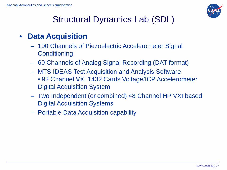
• Data Acquisition– 100 Channels of Piezoelectric Accelerometer Signal
Conditioning– 60 Channels of Analog Signal Recording (DAT format)– MTS IDEAS Test Acquisition and Analysis Software▪ 92 Channel VXI 1432 Cards Voltage/ICP AccelerometerDigital Acquisition System
– Two Independent (or combined) 48 Channel HP VXI basedDigital Acquisition Systems
– Portable Data Acquisition capability

National Aeronautics and Space Administration
www.nasa.gov
Thermal Vacuum Test Facilities
• NASA GRC at Lewis Field has six thermal vacuum chambers(VF-6, VF-10, VF-13, VF-17, VF-20 and VF-67) ranging fromapproximately 3 to 25 ft diameter by 5 to 70 ft long, that operatewith a base pressure on the 10-6 to 10-7 torr scale, using full orpartial liquid nitrogen cold shrouds
National Aeronautics and Space Administration
www.nasa.gov
Thermal Vacuum Test Facilities
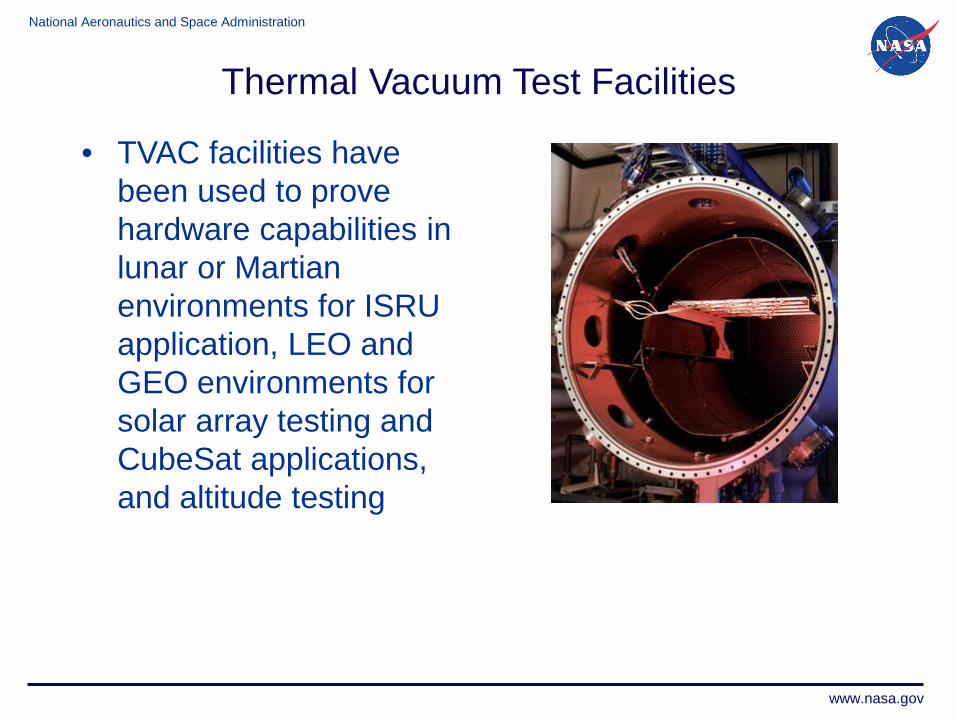
• TVAC facilities havebeen used to provehardware capabilities inlunar or Martianenvironments for ISRUapplication, LEO andGEO environments forsolar array testing andCubeSat applications,and altitude testing

National Aeronautics and Space Administration
www.nasa.gov
Kinetic High Altitude Simulator (KHAS) Description• KHAS is slated to be a flexible, world-class environmental simulation
facility. KHAS will be capable of simultaneous temperature, altitude, andvibration testing of operational test articles per RTCA DO-160F.
Industry Problem• Currently, the majority of airborne equipment testing per RTCA DO-160F
is performed using a multitude of test facilities. This can require thecustomer to modify the test articles or even develop test-specific articlesin order to accommodate specific tests and facilities. All of this leads toprolonged test schedules, complex logistics management, and processinefficiencies leading to increased overall test costs.
Our Solution• KHAS will enable simultaneous testing within a single facility. Unlike
other test apparatuses, KHAS will enable test articles to be operationalduring testing within a desired environmental condition, therebyproviding a more realistic test.
Current Status• Phase 1 feasibility analysis complete, preliminary parts list generated
Thermal Vacuum Test Facilities

National Aeronautics and Space Administration
www.nasa.gov
Thermal Vacuum Test Facilities
KHAS Concept – Full Capability
• Inner Diameter = 39”• Inner Height = 39”• 8 feedthru ports
• Power• I&C• LO2/GO2 (fuel port #1)• LH2/GH2 (fuel port #2)• LN2/GN2
(atmosphere)• Spares (3)
• Lid port is used by facility
KHAS High-Level Capabilities• Enables simultaneous operational testing per
RTCA DO-160F, Sections:• 4.0 – Temperature and Altitude• 5.0 – Temperature Variation• 8.0 – Vibration• Future Extensibility may add other
effects, based on market demand (e.g.humidity, electrical/signal effects, etc.)
• Portability: Entire system will be portable• Test Article Weight: Up to 550 lbs• Simulated Altitude: Up to 65,000 ft.• Temperature Range: -100°F (-60°C) to
180°F (85°C)• Temperature Variability Rate: Up to
60°C/min• Test Duration: 4+ hrs
• Current concept design has beenoptimized to minimize operating costs
• Frequency Range: 10 – 2000 Hz• Integration and Operations in
collaboration with world-class vibrationsexperts at NASA GRC SDL
KHAS Concept - COTS• Alternatively, We
could develop aCOTS option(includes temp &altitude, excludesvibration fromsimultaneoustesting). Later, thefull–capability optioncould be developed.

National Aeronautics and Space Administration
www.nasa.gov16
Electromagnetics Interference (EMI) Lab
The EMI Lab has successfully verified every piece of flight hardware to leave GRC since its completion in circa 1995.
Planned upgrades to the facility including anechoic chamber treatment for small test articles, mode-tune reverberation chamber characterization for large test articles, and high frequency test equipment.
16

National Aeronautics and Space Administration
www.nasa.gov17
Electromagnetics Interference (EMI) Lab
The Electromagnetic Interference (EMI) Laboratory offers several Electromagnetic Compatibility (EMC) services like EMC hardware design to meet the desired requirement, specification comparisons, consultation during design development, and prefabrication analyses. The EMI Lab provides intermediate testing as the design progresses, testing for shielding effectiveness, filtering, and grounding, final qualification testing of experiments in flight configuration, and testing at customer locations for items too large to fit in the EMI Laboratory shielded room.
This facility consists of three shielded rooms, two test chambers, and a control room. All walls, ceiling, and floors are constructed of 26-gauge galvanized steel sheets laminated to both sides of a structure core. The rooms meet the electromagnetic wave attenuation requirements used by the National Security Agency (NSA). They prevent transmission of electromagnetic waves into, or out of, the enclosure, which provides low electric and magnetic field ambient conditions. Electrical power is provided through filtered AC lines to eliminate transfer of interfering signals such as radio, TV, and RADAR.
The large shielded enclosure is a fully functional package with support for stirred and tuned mode operation with Statistical Mode Averaged Reverberation test. This methodology of test is good for Immunity test or shielding effectiveness test.

National Aeronautics and Space Administration
www.nasa.gov18
Electromagnetics Interference (EMI) Lab
Emissions Method
CE01 Automated
CE03 Automated
CE07 Manual
RE02 Automated
RE04, RE101 Automated
Magnetic Automated/Manual (H-Field)
Susceptability Method
CS01 Automated
CS02 Automated
CS06 Manual
RS02 Manual
RS03 Automated
RE03-PL Automated
National Aeronautics and Space Administration
www.nasa.gov19
Electromagnetics Interference (EMI) Lab
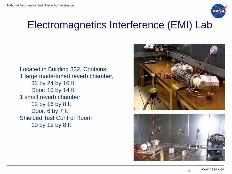
Located in Building 332, Contains:1 large mode-tuned reverb chamber,
32 by 24 by 16 ftDoor: 10 by 14 ft
1 small reverb chamber12 by 16 by 8 ftDoor: 6 by 7 ft
Shielded Test Control Room10 by 12 by 8 ft
19
National Aeronautics and Space Administration
www.nasa.gov
Electromagnetics Interference (EMI) Lab
2
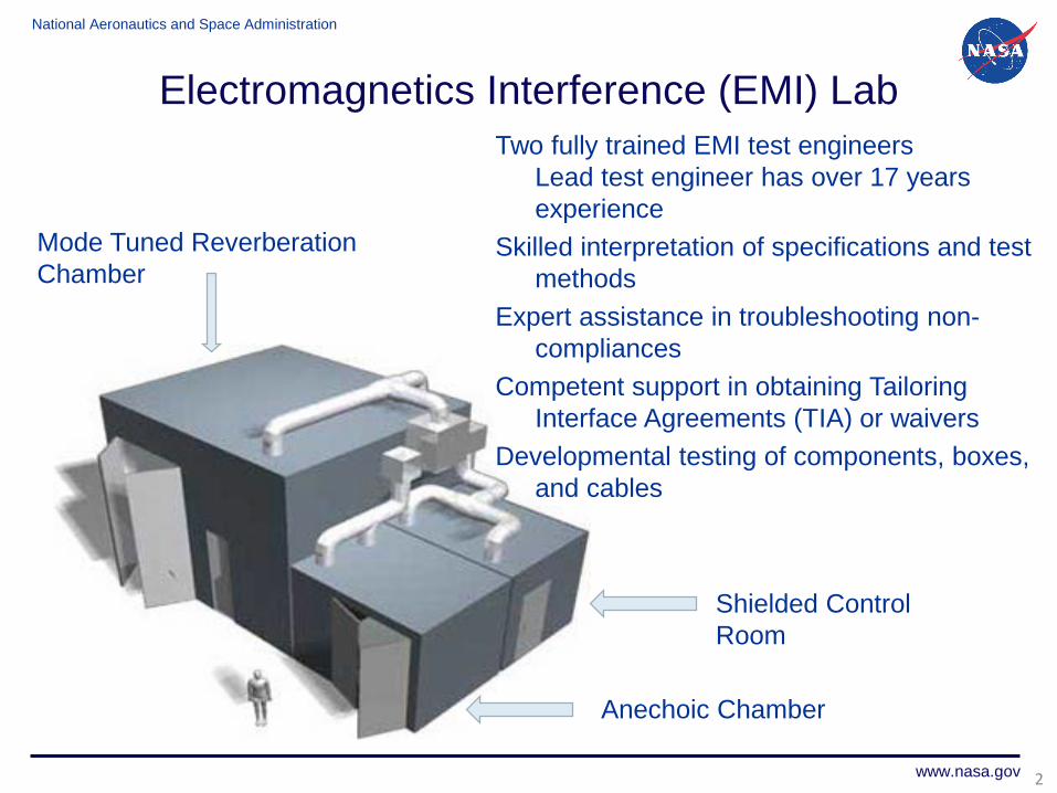
Mode Tuned Reverberation Chamber
Anechoic Chamber
Shielded Control Room
Two fully trained EMI test engineersLead test engineer has over 17 years experience
Skilled interpretation of specifications and test methods
Expert assistance in troubleshooting non-compliances
Competent support in obtaining Tailoring Interface Agreements (TIA) or waivers
Developmental testing of components, boxes, and cables

National Aeronautics and Space Administration
www.nasa.gov21
Electromagnetics Interference (EMI) Lab
• Large Chamber– Reverberation chamber simulates cavity environments– Fields are made statistically uniform by rotating the two
stirring paddles– This is becoming the “gold standard” for a robust
susceptibility test, because energy impinges on the system under test from all directions and polarities
– Size of test article (ft.)can be 17 ½ L x 8 ½ W x 7 H• Anechoic Chamber
– Reverberation chamber simulates free space– Walls are covered by ferrite tiles to absorb lower frequencies
and carbon impregnated composite cones to absorb higher frequencies
– Size of test article (ft.) can be 7 ¾ L x 2 ¼ W x 2 ½ H

National Aeronautics and Space Administration
www.nasa.gov22
Electromagnetics Interference (EMI) Lab
• Control Room– Shielded control room keeps noise from infecting the test
chambers– Stand-alone computers control the test equipment– Shielded feed-throughs allow customers’ support equipment to
interface with article under test– Equipment available on-site to support a wide variety of EMI
testing:MIL-STD-461FIndirect LightningIEC 61000-4-21RTCA/DO-160

National Aeronautics and Space Administration
www.nasa.gov23
Electromagnetics Interference (EMI) Lab

National Aeronautics and Space Administration
www.nasa.gov24
Electromagnetics Interference (EMI) Lab
EMI Test Categories

National Aeronautics and Space Administration
www.nasa.gov
Creek Road Cryogenic Complex

National Aeronautics and Space Administration
www.nasa.gov
Creek Road Cryogenic Complex• Construction completed Fall 2003, state-of-art facility and data acquisition• Space simulation, launch profiles and high altitude• Creek Road Cryogenic Complex (CRCC) consists of 4 separate test cells:
Small Multi-purpose Research Facility (SMiRF), Cryogenics Component Lab 7 (CCL-7), Cryomotor Pad*, and 20K – 90K Calorimeter Test Bed*
26
*Information available upon request

National Aeronautics and Space Administration
www.nasa.gov
CapabilitiesTest Fluids: LH2 - 4500 gal (17,000 l), LN2 - 6000 gal (22,700 l), LO2 - 3600 gal
(13,600 l), LHe (500 liters), LCH4 - 6000 gal (22,700 l)Vacuum Environment:
Continuous: 5 x 10⁻⁶ torrAscent Profile: 760 to 1 x 10⁻² torr in 2 min.
Thermal Environment: Shroud (110K to 390K) Programmable to simulate diurnal cycles
Test Article Size (width x height)With Shroud: 44” x 65” (1.1 m x 1.6 m)W/ Out Shroud: 71” x 101” (1.8 m x 2.3 m)
Data System:424 Recordable channels at speeds up to 1 Hz64 Recordable channels at speed up to 0.1 Hz
SMIRF: provides the ability to simulate space, high altitude, & launch pressure environments; conduct calorimetry tests on prototype insulation systems; and handle hazardous gaseous and cryogenic flammable fluids without compromising on personal safety; specializes as a small scale screening facility for concept and component testing; supports Cryogenic Fluid Management (CFM) technology development (thermal control, liquid supply, low gravity mass gauging), planetary simulation, and any test requiring a hazardous commodity in a thermal vacuum chamber
Creek Road Cryogenic Complex

National Aeronautics and Space Administration
www.nasa.gov
Creek Road Cryogenic ComplexSMiRF:• Highly configurable test cell• Cryogens (LH2, LCH4, LO2, LN2)• Gases (H2, CH4, He, N2, O2, CO2)• 1st floor Vac. Chamber (7400 L)• 2nd floor piping & VC lid access• Separate oxygen & flammable propellant systems• Test articles up to 1.8 m x 2.3 m• Safety handled w/ rollup doors, explosion proof
equipment, gas detection, exclusion zone based on appropriate quantity-distance calculations
• Remotely operated for safety

National Aeronautics and Space Administration
www.nasa.gov
RBO I test tank shown suspended within SMiRF vacuum tank
SMiRF Capabilities – cont’d
• Steady State ullage pressure control -0.025 psi (1.7 mBar)
• Programmable thermal shroud (cold wall) boundary temperatures from -260F to 240F (110K to 390K)
• Data System – ~500 recordable channels at speeds of 1 Hz to 0.1 Hz
• Vacuum Chamber diameter ~ 6 ft (1.8 m)• Multi-Layer Insulation (MLI) custom onsite
fabrication and installation• Vacuum levels as low as 3e-6 torr• Controlled launch ascent pressure profile
capability – Match current ELV fleet• Residual Gas Analyzer on chamber
Thermal Shroud
Creek Road Cryogenic Complex

National Aeronautics and Space Administration
www.nasa.gov
Volume = 58 ft3 (1.6 m3)MAWP = LN2 - 250 psi (17.2 Bar)
LH2 - 150 psi (10.3 Bar)
Creek Road Cryogenic ComplexSMiRF – Numerous pressure vessels

National Aeronautics and Space Administration
www.nasa.gov
Creek Road Cryogenic Complex
Volume = 6 ft3 (0.17 m3)MAWP = LN2 - 250 psi (17.2 Bar)
Volume = 6 ft3 (0.17 m3)MAWP = LN2 - 250 psi (17.2 Bar)
Volume = 49 ft3 (1.39 m3)MAWP = LH2 - 50 psi (3.45 Bar)Aluminum construction
SMiRF – Numerous pressure vessels cont.

National Aeronautics and Space Administration
www.nasa.gov
Creek Road Cryogenic ComplexCryogenic Components Lab (CCL-7)CCL-7 is a smaller version of SMiRF with similar capabilities. It is a highly configurable test cell providing the ability to simulate space, conduct highly accurate calorimetry tests (20K to 90K or -423F to -297F) on prototype insulation systems, and handle hazardous gaseous and cryogenic flammable fluids without compromising on personal safety. Capabilities
Cryogenic Test Fluids: LHe, LH2, LN2, LAr, LO2, LCH4 or other as requiredGases: He, H2, N2, Ar, O2, CH4 or other as required Vacuum Environment: Continuous 1 x 10⁻⁶ torrTest Article Size (width x height): 30” x 56” (0.76 m x 1.42 m)Data System:
320 Recordable channels at nominal speed of 1 Hz6 Recordable channels at speed up to 6250 Hz
Numerous pressure vessels ranging from 0.2 ft3 (0.006 m3) to 23 ft3 (0.65 m3) with pressures up to 100 psig (6.9 bar) Residual Gas AnalyzerEjector system to sub-cool cryogens

National Aeronautics and Space Administration
www.nasa.gov
Creek Road Cryogenic Complex
Double Wall Pressure Vessels –Volume = 23 ft3 (0..65 m3)MAWP = 100 psi (6.9 Bar)Inner vessel 30” x 56” (0.76 m x 1.42 m)
CCL-7 – Numerous pressure vessels
National Aeronautics and Space Administration
www.nasa.gov
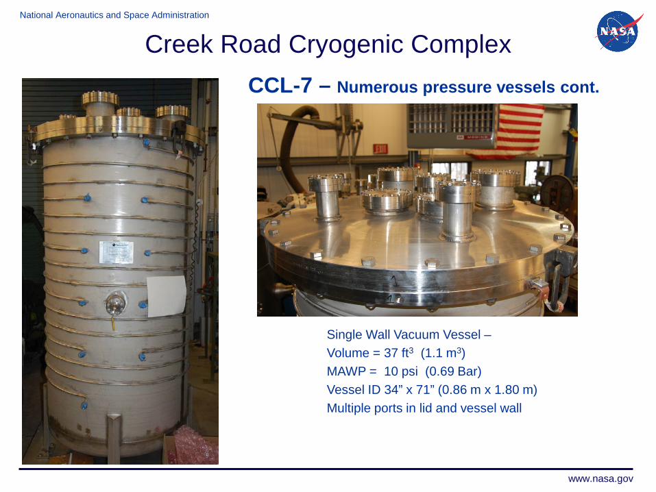
CCL-7 – Numerous pressure vessels cont.
Single Wall Vacuum Vessel –Volume = 37 ft3 (1.1 m3)MAWP = 10 psi (0.69 Bar)Vessel ID 34” x 71” (0.86 m x 1.80 m)Multiple ports in lid and vessel wall
Creek Road Cryogenic Complex