Extraction Metallurgy Part 2: Case studies Dr. C.B. Perry (C306) Chem 3033.
123
Extraction Metallurgy Part 2: Case studies Dr. C.B. Perry (C306) http://www.gh.wits.ac.za/chemnotes Chem 3033
-
Upload
victoria-singleton -
Category
Documents
-
view
218 -
download
0
Transcript of Extraction Metallurgy Part 2: Case studies Dr. C.B. Perry (C306) Chem 3033.

Extraction MetallurgyPart 2: Case studies
Dr. C.B. Perry (C306)
http://www.gh.wits.ac.za/chemnotes
Chem 3033

Extraction MetallurgyPart 2: Case studies
•Copper – Pyrometallurgy route and environmental concerns. The hydrometallurgical alternative.
•Hydrometallurgical processes – ion exchange processes, solvent extraction, and bacterial leaching.
•Iron – Pyrometallurgy and the blast furnace.
•Silicon – The electric arc furnace. Purification by the Czochralski process.
•Aluminium – Electrolytic reduction.
•The siderophiles – The extraction of Au and the Pt group metals and their purification.
Pyrometallurgy of copper
Reminder: Pyrometallurgy is the use of heat to reduce the mineral to the free metal, and usually involves 4 main steps:
1.Calcination: thermal decomposition of the ore with associated elimination of a volatile product.
2.Roasting: a metallurgical treatment involving gas-solids reactions at elevated temperatures.
3.Smelting: a melting process which separates the chemical reaction products into 2 or more layers.
4.Refining: treatment of a crude metal product to improve its purity.
Pyrometallurgy of copper
Cu ore usually associated with sulphide minerals.
Most common source of Cu ore is the mineral chalcopyrite (CuFeS2), which accounts for ± 50% of Cu production.
Other important ores include:chalcocite [Cu2S], malachite [CuCO3 • Cu(OH)2], azurite [2CuCO3 • Cu(OH)2], bornite (3Cu2S • Fe2S3), covellite (CuS).

Pyrometallurgy of copper
The following steps are involved in Cu extraction:
1.Concentration
2.Roasting
3.Smelting
4.Conversion
5.Refining
Pyrometallurgy of copper
1. Concentration
Finely crushed ore concentrated by the froth-flotation process:
• Ground ore mixed with xanthates (salts & esters of xanthic acid), dithiophosphates, or thionocarbamates. These make the ore surface hydrophobic.
• Ore then introduced into a water bath where air is bubbled through the suspension.
• Finely divided hydrophobic ore particles latch on to the air bubbles and travel to the surface where a froth is formed.

Pyrometallurgy of copper
1. Concentration (cont.)
• The froth containing the Cu ore is skimmed off and reprocessed.
• The remaining material (sand particles & other impurities) sink to the bottom & is discarded or reprocessed to extract other elements.

Pyrometallurgy of copper
1. Concentration (cont.)
Froth-flotation
Pyrometallurgy of copper
2. Roasting
• Involves partial oxidation of the sulphide mineral with air at between 500C and 700C.
• For chalcopyrite, the main reactions are:CuFeS2(s) + 4O2(g) → CuSO4(s) + FeSO4(s)
4CuFeS2(s) + 13O2(g) → 4CuO(s) + 2Fe2O3(s) + 8SO2(g)
• Reactions are exothermic, roasting is an autogenous process requiring little or no additional fuel.
• NB, not all the sulphides are oxidised, only around 1/3. Rest remain as sulphide minerals.
• The gases produced contain around 5 – 15% SO2, which is used for sulphuric acid production.

Pyrometallurgy of copper
2. Roasting (cont.)
Objectives of roasting:
1) Remove part of the sulphur.
2) Convert iron sulphides into iron oxide and iron sulphate to facilitate removal during smelting.
3) To pre-heat the concentrate to reduce amount of energy needed by the smelter.

Pyrometallurgy of copper
3. Smelting
• Smelting consists of melting the roasted concentrate to form 2 molten phases:
1) a sulphide “matte”, which contains the iron-copper sulphide mixture.
2) an oxide slag, which is insoluble in the matte, and contains iron oxides, silicates, and other
impurities. • Smelting is carried out at around 1200C, usually with a
silica flux to make the slag more fluid.
• The matte layer sinks to the bottom, and the slag layer floats on top of the matte & is tapped off & disposed of.

Pyrometallurgy of copper
3. Smelting (cont.)
• The main reaction is the reduction of copper oxides (formed during roasting) back into copper sulphide to ensure that they migrate into the matte phase:
FeS(l) + 6CuO(l) → 3Cu2O(l) + FeO(l) + SO2(g)FeS(l) + Cu2O(l) → FeO(l) + Cu2S(l)
Cu2S(l) + FeS(l) → Cu2S•FeS(l) (matte)

Pyrometallurgy of copper
4. Conversion
• After smelting, matte contains from between 30 to 80% Cu in the form of copper sulphide.
• The sulphur is removed by selective oxidation of the matte with O2 to produce SO2 from S, but leave Cu metal.
• Converting is carried out in two stages: 1) an iron removal stage, and 2) a copper-making stage.
Pyrometallurgy of copper
4. Conversion (cont.)
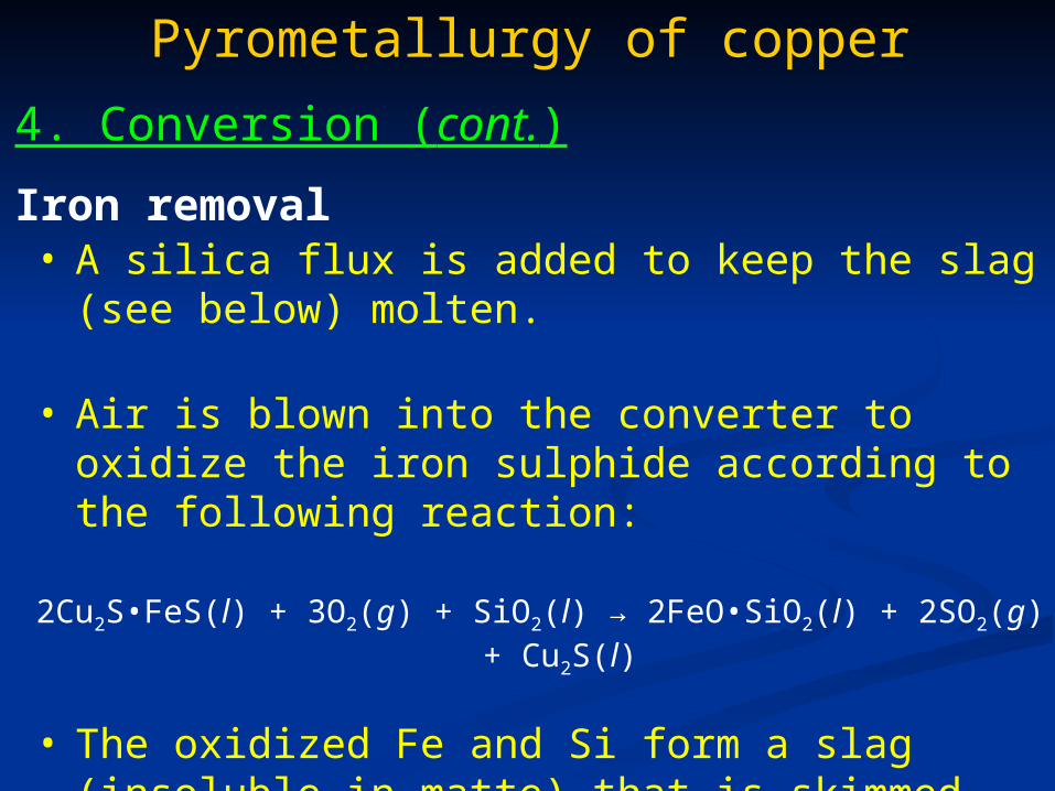
Iron removal• A silica flux is added to keep the slag (see below)
molten.
• Air is blown into the converter to oxidize the iron sulphide according to the following reaction:
2Cu2S•FeS(l) + 3O2(g) + SiO2(l) → 2FeO•SiO2(l) + 2SO2(g) + Cu2S(l)
• The oxidized Fe and Si form a slag (insoluble in matte) that is skimmed off & disposed off.

Copper making
• The sulphur in the Cu2S can now be oxidized to leave behind metallic copper according to the following reaction:
Cu2S(l) + O2(g) → 2Cu(l) + SO2(g)
• The end product is around 98.5% pure & is known as blister copper because of the broken surface created by the escape of SO2 gas.
Pyrometallurgy of copper
4. Conversion (cont.)

Pyrometallurgy of copper
5. Refining
• The copper is refined by electrolysis.
• The anodes (cast from blister copper) are placed into an aqueous CuSO4/H2SO4 solution.
• Thin sheets of highly pure Cu serve as the cathodes.
• Application of a suitable voltage causes oxidation of Cu metal at the anode.
• Cu2+ ions migrate through the electrolyte to the cathode, where Cu metal plates out.

Pyrometallurgy of copper
5. Refining (cont.)
• Metallic impurities more active then Cu are oxidized at the anode, but don’t plate out at the cathode.
• Less active metals are not oxidized at the anode, but collect at the bottom of the cell as a sludge.
• The redox reactions are:
Cu(s) Cu2+(aq) 2e-
Cu2+(aq) + 2e- Cu(s) Ered = -0.83V

Pyrometallurgy of copper
5. Refining (cont.)

Pyrometallurgy of copper
Environmental impact
• Large amount of gases produced present air pollution problems, in particular SO2 gas acid rain.
• Dust produced contains heavy metals such as mercury, lead, cadmium, zinc health problems.
• Waste water contaminated with:Insoluble substances, mostly waste sludge (finely ground rock).Soluble substances (heavy metals, sulphates).Chemicals from flotation process.

Hydrometallurgy of copper
Advantages
• Much more environmentally friendly than pyrometallurgy.
• Compared to pyrometallurgy, only a fraction of the gases liberated into the atmosphere.
• Emissions of solid particles comparatively non-existent.
Disadvantages• Large amount of water used, greater potential for
contamination.
• Waste waters contain soluble metal compounds, chelating compounds & organic solvents.

Hydrometallurgy of copper
The following steps are involved:
1.Ore preparation
2.Leaching
3.Solution purification
4.Metal recovery

Hydrometallurgy of copper
1. Ore preparation
• Ore undergoes some degree of comminution (crushing & pulverisation) to expose the Cu oxides & sulphides to leaching solution.
Hydrometallurgy of copper
1. Ore preparation (cont.)
• Amount of comminution depends on quality of ore:Higher grade ore – more comminution.Lower grade ore – less comminution.(Why??)
• If possible, ore is pre-concentrated; reject ore that contains very little Cu.

Hydrometallurgy of copper
2. LeachingDefinition : The dissolution of a mineral in a solvent, while leaving the gangue (rock or mineral matter of no value) behind as undissolved solids.
• Cu is normally leached by one of three methods:
(a) Dump leaching
(b) Heap leaching
(c) Bacterial leaching
Hydrometallurgy of copper
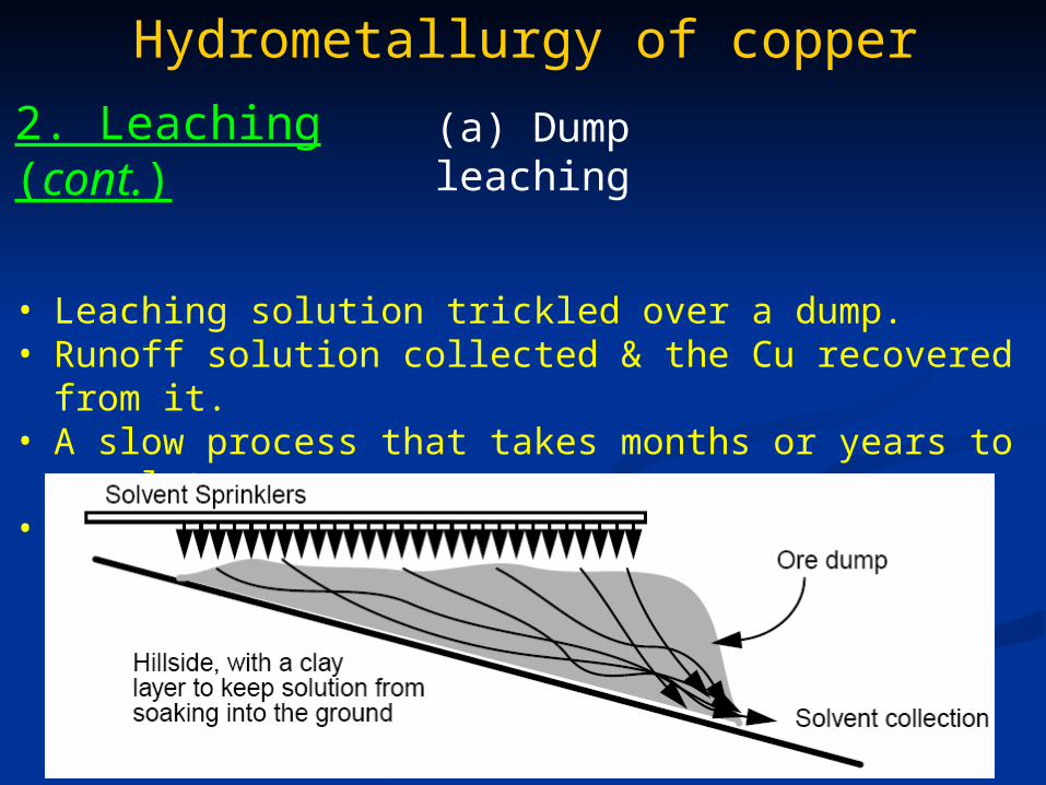
2. Leaching (cont.) (a) Dump leaching
• Leaching solution trickled over a dump.• Runoff solution collected & the Cu recovered from it.• A slow process that takes months or years to complete.• Typically only around 60% of the Cu in the dump is
recovered.

Hydrometallurgy of copper
2. Leaching (cont.) (b) Heap leaching
• Similar to dump leaching except ore not simply dumped on a hillside, but is crushed to gravel size & piled onto an artificial pad.
• After leaching (6 months to 1 year) gangue is removed from pad, disposed of & replaced with fresh ore.

Hydrometallurgy of copper
2. Leaching (cont.)
Leaching reactions
Nature of ore determines if leaching is non-oxidative or oxidative.
Non-oxidative leaching: No change in oxidation state.
e.g. (1) dissolution of copper sulphate by water:CuSO4(s) + H2O(l) Cu2+(aq) + SO4
2-(aq)
(2) dissolution of alkaline materials by acid:Cu2(OH)2•CO3(s) + 2H2SO4(aq) 2CuSO4(aq) + CO2(g) + 3H2O(l)

Hydrometallurgy of copper
2. Leaching (cont.)
Oxidative leaching: Many ores only soluble once oxidised.
e.g. covellite (CuS) much more soluble if oxidised to CuSO4
CuS(s) + O2(g) CuSO4(aq)
CLASS EXERCISE : work out which species is oxidised, and which is reduced, and write out the balanced half reactions for each.
SOLUTION: CuS Cu = +2, S = -2O2 O = 0CuSO4 Cu = +2, O4 = -8, S = +6
S-2 S+6 + 8e- (oxidation)2O2 + 8e- 4O2
- (reduction)

Hydrometallurgy of copper
2. Leaching (cont.) (c) Bacterial leaching
• Several bacteria, especially Thiobacilli, are able to solubilise metal minerals by oxidising ferrous to ferric iron, as well as elemental sulphur, sulphide, and other sulphur compounds to sulphate or sulphuric acid.
• 20 to 25% of copper produced in the USA, and 5% of the worlds copper is obtained by bacterial leaching.
• Very slow process; takes years for good recovery
• But low investment and operating costs.

Hydrometallurgy of copper
2. Leaching (cont.) (c) Bacterial leaching
Thiobacilli
• Are acidotolerant; some grow at pH’s as low as 0.5
• Are tolerant against heavy metal toxicity.
• Are chemolithoautotrophs (C source is CO2 & energy derived from chemical transformation of inorganic matter).
Hydrometallurgy of copper
2. Leaching (cont.)Mechanisms
Generalised reaction : M(II)S + 2O2 M2+ + SO42-
• Two mechanisms: (a) indirect mechanism involving the ferric-ferrous cycle, and (b) direct mechanism involving physical contact of the organism with the sulphide mineral.
(c) Bacterial leaching

Hydrometallurgy of copper
2. Leaching (cont.)Mechanisms: Indirect
First step: ferrous sulphate is converted into ferric sulphate by the action of Acidithiobacillus ferrooxidans:
(c) Bacterial leaching
4FeSO4 + O2 + 2H2SO4 2Fe2(SO4)3 + 2H2O
CLASS EXERCISE : work out which is ferric- and which is ferrous sulphate, and write out the balanced half reactions for each.
FeSO4 – SO42- Fe2+ (ferrous)
2Fe2(SO4)3 – 3 × SO42- = -6, but 2 × Fe Fe3+ (ferric)

Hydrometallurgy of copper
2. Leaching (cont.)Mechanisms: Indirect
(c) Bacterial leaching
2Fe2+ 2Fe3+ + 2e- (oxidation)O2 + 2e- 2O2- (reduction)
• Ferric sulphate is a strong oxidising agent capable of dissolving a range of sulphide minerals.
• In the case of chalcopyrite:
CuFeS2 + 2Fe2(SO4)3 CuSO4 + 5FeSO4 + 2S
Hydrometallurgy of copper
2. Leaching (cont.)Mechanisms: Indirect
(c) Bacterial leaching
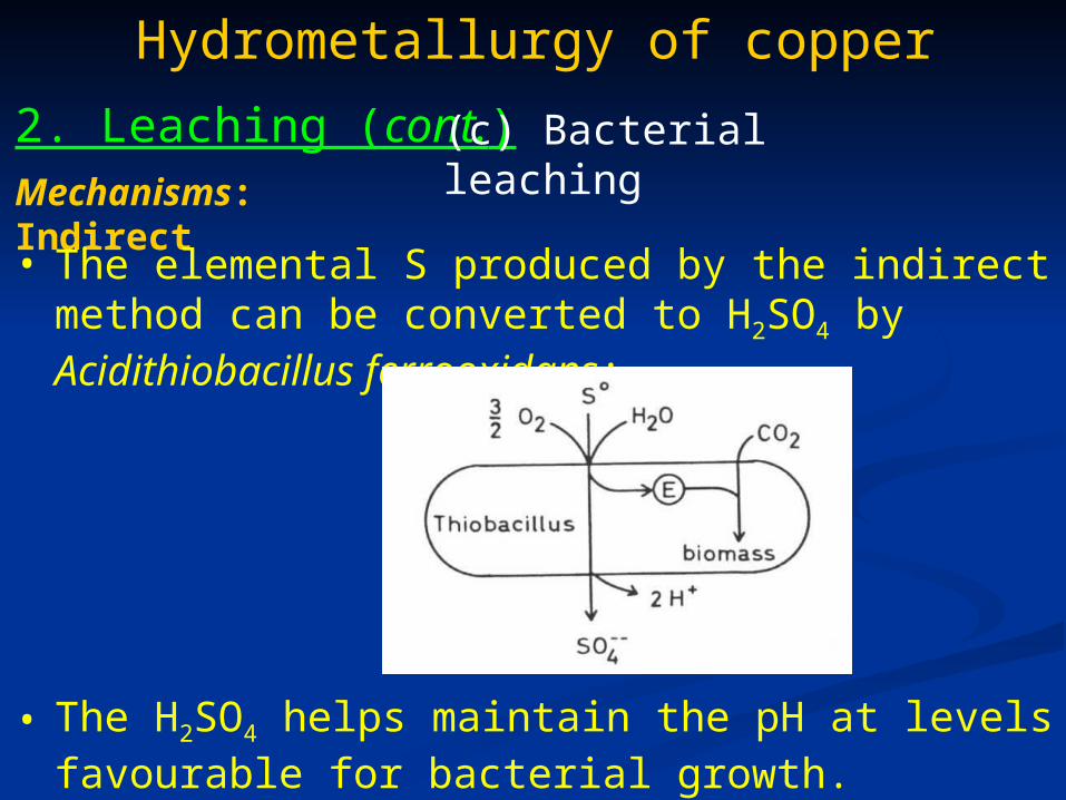
• The elemental S produced by the indirect method can be converted to H2SO4 by Acidithiobacillus ferrooxidans:
• The H2SO4 helps maintain the pH at levels favourable for bacterial growth.

Hydrometallurgy of copper
2. Leaching (cont.)Mechanisms: Direct
(c) Bacterial leaching
• Bacteria actually adheres to the mineral surface prior to enzymatic attack.
• The mineral is oxidised with oxygen to sulphate and metal cations without any detectable intermediate occurring.
• In the case of covellite:
CuS + 2O2 CuSO4

Hydrometallurgy of copper
3. Solution Purification
• Leaching reactions not perfectly selective other elements in solution as well, not just Cu. These need to be removed.
• After leaching, Cu in solution can be very dilute. need a way to concentrate it.
• Both of these are generally done using ion exchange processes, the two most common being ion exchange chromatography, and solvent extraction.

Hydrometallurgy of copper
3. Solution Purification
Ion exchange chromatography
• DEFINITION: a solution containing a mixture of metal ions is contacted with a resin that is insoluble in the metal-ion solution.
• Ion-exchange resin consists of an inert solid phase to which labile functional groups are chemically bonded.
• Functional groups can either be acidic (H+) or basic (OH–) groups that exchange with cations (M+) or anions (M–), respectively.
• The ion-exchange process is reversible.

Hydrometallurgy of copper
3. Solution Purification
Ion exchange chromatography
• Carboxyl groups exchanges the ion it currently holds (H+) for a Cu2+ ion.
• The Cu2+ is later released by contacting it with a stripping solution (very high H+ conc.).
Hydrometallurgy of copper
3. Solution Purification: Solvent extraction
• DEFINITION: a method to separate compounds based on their relative solubilities in 2 different immiscible liquids.
• In industry, this is usually set up as a continuous process

Hydrometallurgy of copper
3. Solution Purification: Solvent extraction

Hydrometallurgy of copper
• Organic + aqueous stream pumped into a mixer.• Organic (containing an extractant) and aqueous
components mix, and ion transfer occurs between them.• Once ion transfer is complete (equilibrium), mixture is
allowed to separate.• Aqueous solution is removed & the organic phase
(containing the Cu2+) is mixed with an aqueous stripping solution.
• Cu2+ moves back into the aqueous phase, and the two phases are again allowed to separate.
• The aqueous phase (containing the Cu2+) is removed & the organic phase is recycled back into the first mixer.
3. Solution Purification: Solvent extraction

Hydrometallurgy of copper
• The most successful extractants for copper are of the ortho-hydroxyoxime type:
R
N
R1
OHOH
R = alkyl ,phenyl, or H
R1 = alkyl
• Function by means of a pH-dependent cation-exchange mechanism:
Cu2+ + 2HA CuA2 + 2H+
3. Solution Purification: Solvent extraction
(where H in HA denotes the replaceable, phenolic proton)
Extractants
Hydrometallurgy of copper
3. Solution Purification: Solvent extraction
• At low pH (1.5 – 2.0) the ortho-hydroxyoxime extractant complexes the Cu.
• During back-extraction (stripping stage) the pH is lowered further, releasing the Cu, and regenerating the hydroxyoxime for recycle to the extraction stage.
• Aqueous feeds (leach solution) typically contain more iron per litre than copper. For commercial success, the extractant must have a greater selectivity for Cu than Fe.
Extractants

Hydrometallurgy of copper
3. Solution Purification: Solvent extraction
Extractants
• Cu2+ forms square-planar complexes with hydroxyoxime:
• H-bonding between the oximic H and the phenolic O affords this 2:1 complex unusual stability.
• The formation constant (K2) for the 2:1 complex is much greater than for the 1:1 complex.
OCu
R
R
N
N
OO
HH
R
R
1
1O

Hydrometallurgy of copper
3. Solution Purification: Solvent extraction
Extractants
• The tris(salicylaldoximato)iron(III) complex is octahedral, and no extended planar ring structure is possible between the 3 oxime ligands.
stability of Fe(III) complex is less than Cu(II) complex, which allows the extraction of Cu to be carried out at lower pH than what is required for efficient Fe extraction.

Hydrometallurgy of copper
4. Metal Recovery:
• At this point, the metal needs to be recovered from solution in the solid form.
• This is either achieved chemically, or electrochemically.

Hydrometallurgy of copper
4. Metal Recovery:
• Dissolved copper will plate out on an iron surface according to the following reaction:
Chemical recovery
Cu2+(aq) + Fe(s) Fe2+(aq) + Cu(s)
Why??
Reduction half-reactions:
Cu2+(aq) + 2e– Cu(s) Ered = +0.34 V
Fe2+(aq) + 2e– Fe(s) Ered = -0.44 V
• Ered for the Cu2+ half-reaction is more positive than for
the Fe2+ half reaction which leads to Cu being reduced and Fe oxidised.

Hydrometallurgy of copper
4. Metal Recovery:
• Solutions containing dissolved copper are thus run through a bed of shredded scrap iron, resulting in the copper ions being plated out as solid Cu on the iron surface.
• For the process to be efficient, the surface of the scrap iron must be large.
Chemical recovery

Hydrometallurgy of copper
4. Metal Recovery:
• An electrochemical process for precipitating metals from solution.
Electrochemical recovery
Electrowinning
• A current is passed from an inert anode through a liquid leach solution containing the metal so that the metal is extracted as it is deposited onto the cathode.
• The anode is made out of a material that will not easily oxidise or dissolve, such as lead or titanium.
Hydrometallurgy of copper
4. Metal Recovery: Electrochemical recovery
Electrowinning

• The anodes consist of unrefined impure metal.
• Current passes through the acidic electrolyte corroding the anode into the solution.
• Refined pure metal deposited onto the cathodes.
• Metals with a greater Ered than Cu (such as Zn and
Fe) remain in solution.
• Metals with a lower Ered than Cu (Au, Ag) accumulate as an “anode sludge” collected & sold for further refining.
Hydrometallurgy of copper
4. Metal Recovery: Electrochemical recovery
Electrorefining
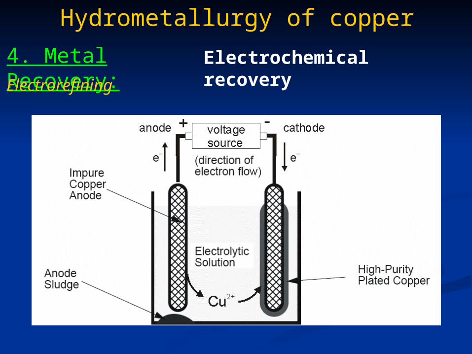
Hydrometallurgy of copper
4. Metal Recovery: Electrochemical recovery
Electrorefining

Hydrometallurgy of copper
Summary:
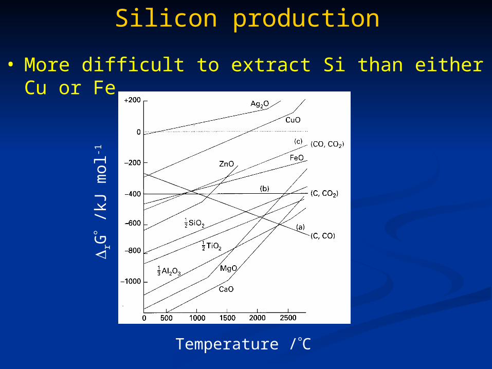
Silicon production
• More difficult to extract Si than either Cu or Fe.
Temperature /C
rG
/kJ
mo
l-1

Silicon production
• Silicon of between 96 to 99% purity is achieved by reduction of quartzite or sand (SiO2, also called silica)
• High temperatures required achieved in an electric arc furnace.
• Reduction carried out in the presence of excess silica to prevent accumulation of silicon carbide (SiC) :
SiO2(l) + 2C(s) Si(l) + 2CO2(g)
2SiC(s) + SiO2(l) 3Si(l) + 2CO(g)

Silicon production
• Silica and carbon fed in through the top, liquid Si collected at the bottom.
• Temps of ± 2000K achieved by an electric arc burning between graphite electrodes.
The electric arc furnace
• An arc forms between the charge and the electrodes.
• The charge is heated both by current passing through the charge and by the radiant energy evolved by the arc.

Silicon productionThe electric arc furnace
• Electric arc furnaces require huge amounts of electricity. A mid-sized furnace would have a transformer rated about 60,000,000 volt-amperes with a secondary voltage between 400 and 900 volts and a secondary current in excess of 44,000 amperes.

Silicon productionApplications• Si is the 2’nd most abundant element in the earth’s
crust (~28%).
• Principal constituent of natural stone, glass, concrete & cement.
• Largest application of pure Si (metallurgical grade) is in the manufacture of Al-Si alloys to produce cast parts (for automotive industry).
• Important constituent of electrical steel (modifies the resistivity & ferromagnetic properties).
• Added to molten cast iron to improve its performance in casting thin sections.

Silicon productionApplications• 2’nd largest application is in the production of
silicones. These are polymers containing Si-O and Si-C bonds. Typically heat-resistant, nonstick, and rubberlike, they are frequently used in cookware, medical applications, sealants, lubricants, and insulation.
• Electronics industry – ultra-pure silicon wafers used in electronic components such as transistors, solar cells, integrated circuits, microprocessors & various semiconductor devices.

Silicon productionPurification• Ultra-pure silicon is required for the production of
semiconductors.

Silicon productionPurification
• Semiconductor-grade Si produced by converting crude Si to more volatile compounds like SiCl4.
• These are then purified by exhaustive fractional distillation.
• Reduced back to Si with pure H2.
• Finally, the high-purity Si is melted and large single crystals are grown by the Czochralski process.
• Electronic grade Si is required to be 99.999999999% pure!

Silicon production
Purification:
• Ultra-pure Si (only a few ppm of impurities) is melted in a crucible.
The Czochralski process
• Dopant impurities (B or P) can be added to make n-type or p-type silicon (influences the electrical conductivity).
• A seed crystal mounted on a rod is dipped into the molten Si.
• Seed crystal rod pulled up & rotated at the same time.
• By carefully controlling the temp gradients, rate of pulling, and rotation speed, a large single-crystal (called a boule) can be extracted from the melt.

Silicon production
Purification: The Czochralski process
Silicon production
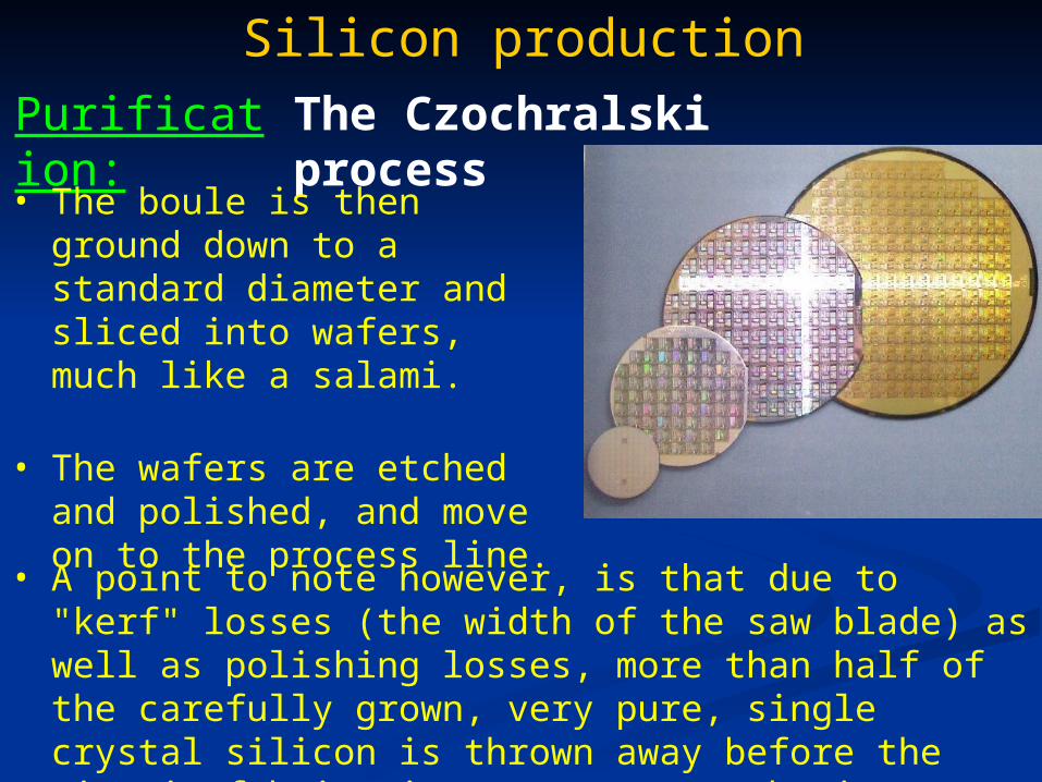
Purification: The Czochralski process
• The boule is then ground down to a standard diameter and sliced into wafers, much like a salami.
• The wafers are etched and polished, and move on to the process line.
• A point to note however, is that due to "kerf" losses (the width of the saw blade) as well as polishing losses, more than half of the carefully grown, very pure, single crystal silicon is thrown away before the circuit fabrication process even begins!

Silicon production
• A new method that uses electrolysis to reduce SiO2 to elemental Si.
• Advantageous because it avoids the high energy costs associated with the older carbothermic route, and also reduces the CO2 emissions considerably.
• SiO2 is usually an insulator, and doesn’t conduct electricity, but it has been shown that a tungsten wire sealed within a quartz tube with the tungsten end exposed, can act as a cathode.
Electrochemical preparation:

Silicon production
• The anode is usually graphite, and the reduction is carried out in a solution of molten CaCl2 at around 850 C.
Electrochemical preparation:
a) SEM of W-SiO2 electrode before reduction.
b) After reduction.c) After washing.d) Side view.

Silicon production
• Conversion of quartz to Si occurs at the three-phase boundary between the SiO2, the electrolyte, and the flattened end of the tungsten wire.
• This provides enough impetus for the electrochemistry to kick in properly as the silica is gradually converted to conducting silicon.
• This reaction should theoretically propagate through the silica electrode, but in reality it grinds to a halt very quickly.
• Reason for this is that the molten electrolyte cannot penetrate through the newly formed Si layer on the surface. three-phase boundary formation halted.
Electrochemical preparation:

Silicon production
• Solution: replace solid quartz electrode with SiO2 powder pressed into pellets & sintered.
• Resulting electrode porous enough to allow electrolyte to penetrate deeply into the material.
Electrochemical preparation:
a) SEM of SiO2 powderb) reduced Si powder.

Silicon production
Electrochemical preparation:

Aluminium production
• Most abundant metallic element in the earth’s crust.
• But, extremely rare in its free form.
• Once considered as a precious metal more valuable than gold!
• Al is a highly reactive metal that forms strong bonds with O.
• Requires a large amount of energy to extract from Al2O3.

Aluminium production
• Cannot be reduced directly by carbon since Al is a stronger reducing agent than C.
• Must therefore be extracted by electrolysis.
• Aluminium production involves two steps: 1) purifying Al2O3 from bauxite (the Bayer process) and 2) converting Al2O3 to metallic Al (The Hall-Heroult process).
• Primary Al ore is bauxite, which consists of:Gibbsite - Al(OH)3 (most extractable form)
Boehmite - AlO•OH (less extractable than Gibbsite)
Diaspore - αAlO•OH (difficult to extract)

Aluminium production
• The hydrated aluminium oxides are first selectively dissolved from bauxite:
The Bayer process: Step 1: Dissolution
Al(OH)3 + NaOH NaAlO2 + 2H2O (Gibbsite dissolution)
AlO•OH + NaOH NaAlO2 + H2O (Boehmite dissolution)
• An undesirable side reaction is the formation of “red mud”, which occurs when Al(OH)3 reacts with dissolved Kaolinite clay:
5Al2Si2O5(OH)4 + 2Al(OH)3 + 12NaOH 2Na6Al6Si5O17(OH)10 + 10H2O
• Red mud formation consumes dissolved Al and represents a Al loss.

Aluminium production
• The digested bauxite now consists of 1 liquid and 2 solid components:
The Bayer process: Step 2: Solid-Liquid Separation
Caustic liquid soln. with dissolved Al.Undissolved coarse material (sand).Precipitated fines (red mud).
• Sand (mainly undissolved silicates) easily removed since they settle very rapidly.
• The red mud is removed by adding a flocculent to increase the settling rate.
• The Al content of the red mud is recovered & forms part of the liquid layer.

Aluminium production
• The remaining solution is supersaturated, containing around 100-175 grams of dissolved Al2O3 per litre.
• Al(OH)3 is precipitated out by adding seed crystals since Al(OH)3 doesn’t crystallise out easily on its own.
• Once the crystals have reached the desired size, they are removed, washed, and filtered.
• The spent liquor is reheated, recausticised and recycled.
The Bayer process: Step 3: Precipitation

Aluminium production
• Wet crystals of Al(OH)3, obtained from the precipitation step are dried by heating to around 1300 – 1500 C.
• This process also converts the Al(OH)3 to Al2O3:
The Bayer process: Step 4: Calcination
2Al(OH)3 Al2O3 + 3H2O

Aluminium production
• Problems result from the coordination chemistry of Al in basic solutions. Generally accepted structures:
The Bayer process: Problems
• Leads to extensive H-bonding between aluminate ion & solvent, which in turn leads to high viscosity of these solutions.
• In turn leads to problems with materials handling & heat exchange.

Aluminium production
• In addition, the inertness of Al(III) leads to slow rates of crystallisation, requiring large vessels & large volumes of circulating solution & seed material.
The Bayer process: Problems
Aluminium production
• Reactive metals (e.g. Mg and Na) can be produced by electrolysing a molten chloride salt of the metal.
• Not the case for AlCl3 since it sublimes rather than melts.
• Even under sufficient pressure, molten AlCl3 is an electrical insulator & cannot be used as an electrolyte. Would have to be dissolved in a conductive salt (NaCl or KCl).
• Commercially viable production of Al only commenced once the use of cryolite (Na3AlF6) was discovered.
The Hall-Heroult process:

Aluminium production
• Cryolite is electrically conductive, and dissolves Al2O3.
The Hall-Heroult process:

Aluminium production
• Anhydrous Al2O3 melts at over 2000C which is too
high to be used as a molten medium for electrolytic reduction of Al.
• Al2O3 dissolved in cryolite has a m.p. of 1012C & is a good electrical conductor.
• Graphite rods are used as anodes & are consumed in the electrolytic process.
• The cathode is a steel vessel, lined with graphite.
The Hall-Heroult process:
Aluminium production
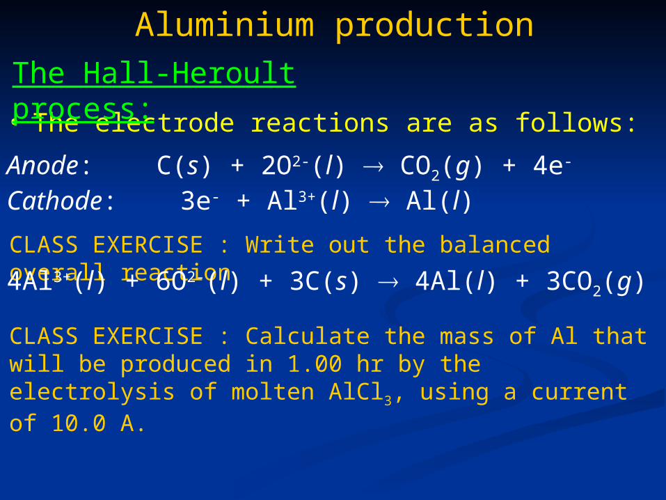
• The electrode reactions are as follows:
The Hall-Heroult process:
Anode: C(s) + 2O2-(l) CO2(g) + 4e-
Cathode: 3e- + Al3+(l) Al(l)
CLASS EXERCISE : Write out the balanced overall reaction
4Al3+(l) + 6O2-(l) + 3C(s) 4Al(l) + 3CO2(g)
CLASS EXERCISE : Calculate the mass of Al that will be produced in 1.00 hr by the electrolysis of molten AlCl3, using a current of 10.0 A.

Aluminium production
The Hall-Heroult process:
• Step 1: calculate the number of coulombs (C) from the current (I) and the time (t):
Q = I × t = 10.0 A × 3600 s = 3.60 × 10⁴ C
• Step 2: find the number of moles of electrons:
electrons m ol 373.0m ol C 96500
C1060.31-
4
FQ
n
F (Faraday constant) = magnitude of electric charge per mole of electrons.

Aluminium production
The Hall-Heroult process:
• Step 3: find the mass of Al produced:
3 mole of electrons needed to produce 1 mol of Al:
3e- + Al3+(l) Al(l)
Number of mol Al = 0.124
Mr Al = 26.98 g mol-1
mass Al = 26.98 g mol-1 × 0.124 mol = 3.34 g Al

Aluminium production
The Hall-Heroult process:
• Electrolytic reduction of Al is costly (3 e- required for every atom of metallic Al reduced).
• The electrical voltage used is only around 5.25 V, but the current required is very high, typically 100,000 to 150,000 A or more!
• Electrical power is the single largest cost in Al production, Al smelters are typically located in areas with inexpensive electric power, like S.A.

Pyrometallurgy of iron
• Still the most important pyrometallurgical process economically.
• The most important sources of iron are hematite (Fe2O3) and magnetite (Fe3O4).
• Prehistorically, iron was prepared by simply heating it with charcoal in a fired clay pot.
• Today, the reduction of iron oxides to the metal is accomplished in a blast furnace.

Pyrometallurgy of iron
Blast furnace:1) Hot gas blast2) Melting zone3) Reduction of FeO4) Reduction of Fe2O3
5) Pre-heating zone6) Feed of ore,
limestone + coke7) Exhaust gases8) Column of ore, coke
+ limestone9) Removal of slag
10) Tapping of molten pig iron11) Waste gas collection

Pyrometallurgy of iron
• The iron ore, limestone, and coke are added to the top of the furnace.
• Coke is coal that has been heated in an inert atmosphere to drive off volatile components (~ 80 – 90% C).
• Coke is the “fuel”, producing heat in the lower part of the furnace. Is also the source of the reducing gases CO & H2.
• Limestone (CaCO3) serves as the source of CaO which reacts with silicates & other impurities in the ore to form slag.

Pyrometallurgy of iron
• Most rocks are composed of silica (SiO2) and silicates (SiO3
2-) & are almost always present in the ore.
• These compounds don’t melt at the furnace temperature & would eventually clog it up.
• An important chemical method to remove these is by use of a flux which combines with the silica & silicates to produce a slag.
• Slag collects at bottom of furnace & doesn’t dissolve in the molten metal.
Slag:

Pyrometallurgy of ironSlag:
CaCO3(s) CaO(s) + CO2(g)
CaO(s) + SiO2(s) CaSiO3(l)
• Slag helps protect the molten iron from re-oxidation.
• The heat of the furnace decomposes the limestone to give calcium oxide.
• CaO (a basic oxide) reacts with silicon dioxide to give calcium silicate.
• Slag is used in road making, and can also be combined with cement.

Pyrometallurgy of iron

Pyrometallurgy of iron
• Air is blown into the bottom of the furnace, and combusts with the coke to raise the furnace temp up to 2000C :
2C(s) + O2(g) 2CO(g) H = -221 kJ
• H2O in the air also reacts with the coke:
C(s) + H2O(g) CO(g) + H2(g) H = +131 kJ
• Since this reaction is endothermic, if the blast furnace gets too hot, water vapor is added to cool it down without interrupting the chemistry.

Pyrometallurgy of iron
• Molten iron is produced lower down the furnace & removed.
• Slag is less dense than iron & can be drained away.
• The iron formed (called pig iron) still contains around 4-5% C, 0.6-1.2% Si, 0.4-2.0% Mn + S and P and needs to be further processed.

Pyrometallurgy of iron
• At around 250C (top of the furnace), limestone is calcinated:
CaCO3(s) CaO(s) + CO2(g)
• Also at the top of the furnace, hematite is reduced:
3Fe2O3(s) + CO(g) 2Fe3O4(s) + CO2(g)
• Reduction of Fe3O4 occurs further down the furnace (~700C):
Fe3O4(s) + CO(g) 3FeO(s) + CO2(g)
• Near the middle of the furnace (1000C) Fe is produced:
FeO(s) + CO(g) Fe(s) + CO2(g)

Pyrometallurgy of iron
• Cast iron is made by remelting pig iron & removing impurities such as phosphorous and sulphur.
• The viscosity of cast iron is very low, & it doesn’t shrink much when it solidifies.
ideal for making castings.
• BUT, it is very impure, containing up to 4% carbon. This makes it very hard, but also very brittle.
• Shatters rather than deforms when struck hard.
• These days cast iron is quite rare, often being replaced by other materials.
Cast iron

Pyrometallurgy of iron
• Pig iron is brittle, and not directly very useful as a material.
• Typically, pig iron is drained directly from the blast furnace (referred to as hot metal), and transported to a steelmaking plant while still hot.
• The impurities are removed by oxidation in a vessel called a converter.
• The oxidising agent is pure O2 or O2 mixed with Ar.
• Air can’t be used as N2 reacts with iron to form iron nitride which is brittle.
Steelmaking

Pyrometallurgy of ironSteelmaking
Iron converter
• O2 blown directly into molten metal.
• Reacts exothermically with C, Si + other impurities.
• C & S expelled as CO and SO2 gas.
• Si oxidised to SiO2 & incorporates into the slag layer.
• Once oxidation complete, contents poured out & various alloying elements added to produce steels.

Pyrometallurgy of iron
• Wrought iron – iron with all the C removed. Soft & easily worked with little structural strength. No longer produced commercially.
• Mild steel – iron containing around 0.25% C. Stronger & harder than pure iron. Has many uses including nails, wire, car bodies, girders & bridges, etc.
• High carbon steel – contains around 1.5% C. Very hard, but brittle. Used for things like cutting tools, and masonry nails.
Types of iron & steel

Pyrometallurgy of iron
• Stainless steel – iron mixed with chromium and nickel. Resistant to corrosion. Uses include cutlery, cooking utensils, kitchen sinks, etc.
• Titanium steel – iron mixed with titanium. Withstands high temperatures. Uses include gas turbines, spacecraft parts, etc.
• Manganese steel – iron mixed with manganese. Very hard. Uses include rock-breaking machinery, military helmets, etc.
Types of iron & steel

Pyrometallurgy of ironThe thermite reaction
• Aluminium metal can reduce Iron(III) oxide (Fe2O3) in a highly exothermic reaction.
• Molten iron is produced at around 3000C.
• Reaction used for thermite welding, often used to join railway tracks.
Fe2O3(s) + 2Al(s) 2Fe(s) + Al2O3(s)

Pyrometallurgy of ironThe thermite reaction

Pyrometallurgy of ironThe thermite reaction
Fe2O3(s) + 2Al(s) 2Fe(l) + Al2O3(s)
Component Hfo (kJ/mol)
Fe2O3(s) -822.2
Al(s) 0
Al2O3(s) -1,669.8
Fe(s) 0
CLASS EXERCISE : calculate the thermal energy that is released in the reaction.
Horxn = (1 mol)(Hf
oAl2O3) + (2 mol)(Hf
oFe) - (1 mol)(Hf
oFe2O3) - (2 mol)(Hf
oAl)
Horxn = (1 mol)(-1,669.8 kJ/mol) + (2 mol)(0) - (1 mol)(-822.2 kJ/mol) - (2mol)(0 kJ/mol)
Horxn = -847.6 kJ mol-1 Exothermic!

Electrowinning of iron
• Studies into iron extraction by electrowinning from sulphate solutions were first carried out around 50 years ago, then subsequently forgotten.
• May become important again in the future as new, more environmentally friendly methods are sought for steelmaking.
The Pyror process:

Electrowinning of iron
• First step is to convert iron pyrite (FeS2) into an acid soluble form (FeS). Achieved by either calcining at 800 to 900 C to expel a loosely-bound S, or by smelting in an electric furnace.
• Step 2 is a leaching step using H2SO4 to extract iron from FeS:
The Pyror process:
FeS(s) + H2SO4(l) FeSO4(l) + H2S(g)
• Step 3: before entering the electrowinning cells, the solution is purged with air to remove any remaining H2S.
Electrowinning of iron
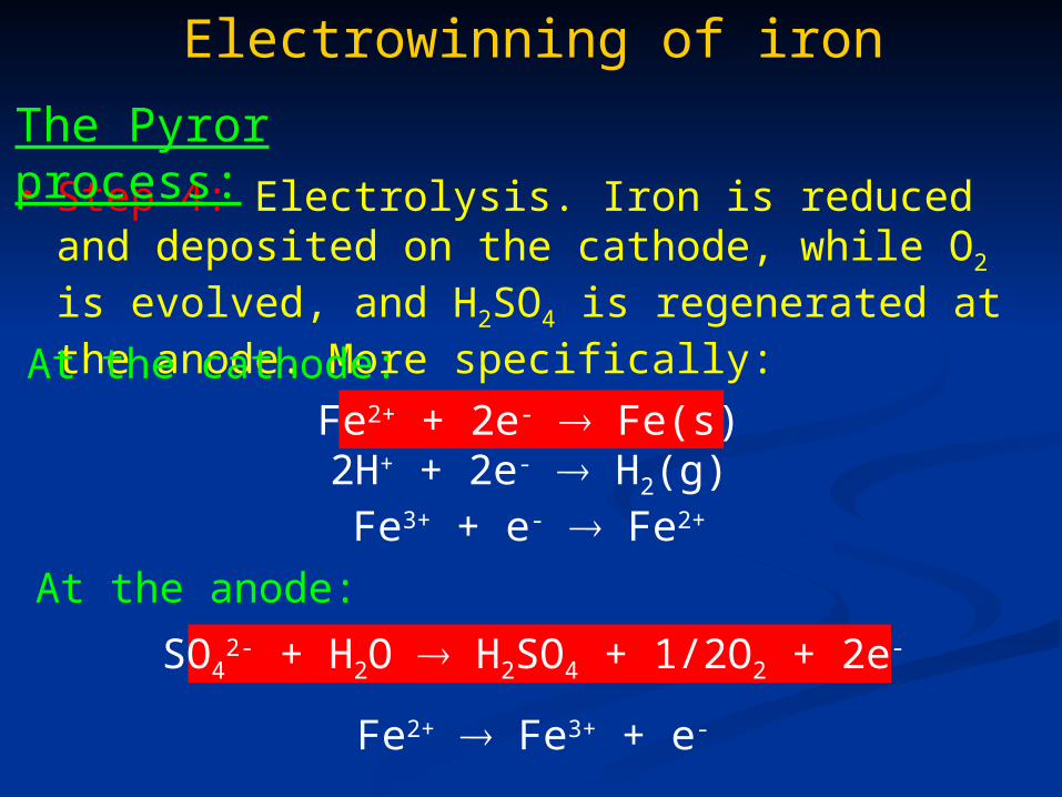
• Step 4: Electrolysis. Iron is reduced and deposited on the cathode, while O2 is evolved, and H2SO4 is regenerated at the anode. More specifically:
The Pyror process:
At the cathode:Fe2+ + 2e- Fe(s)2H+ + 2e- H2(g)Fe3+ + e- Fe2+
At the anode:
SO42- + H2O H2SO4 + 1/2O2 + 2e-
Fe2+ Fe3+ + e-

Electrowinning of iron
The Pyror process:

Electrowinning of iron
The Pyror process:• The process was shown to
be quite efficient. During a 2 year pilot-plant project, a quantity of iron close to 150 tonnes was produced.
• Electrolysis was run for several weeks before stripping was performed, resulting in deposits of 13mm or more in thickness.

Electrowinning of iron
The Pyror process:

Gold extraction
Gold mining Historical:
• Panning – sand and gravel containing gold is shaken around with water in a pan. Gold is much denser than rock, so quickly settles to the bottom of the pan.

Gold extraction
Gold mining Historical:
• Sluicing – water is channelled to flow through a sluice-box. Sluce-box is essentially a man-made channel with riffles (barriers) at the bottom. Riffles create dead-zones in the water current which allows gold to drop out of suspension.
• Sluicing and panning results in the direct recovery of small gold nuggets and flakes.

Gold extraction
Gold mining Modern methods:
• Hard rock mining – used to extract gold encased in rock. Either open pit mining or underground mining.

Gold extraction
Gold ore processing
• The most commonly used process for gold extraction.
• Used to extract gold from low-grade ore.
• Gold is oxidised to a water-soluble aurocyanide metallic complex.
• In this dissolution process, the milled ore is agitated with dilute alkaline cyanide solution, and air is introduced:
Gold cyanidation:
4Au(s) + 8NaCN(l) + O2(g) + 2H2O(l) 4NaAu(CN)2(l) + 4NaOH(l)

Gold extraction
Gold ore processing
• At a slurry concentration of around 50% solids, the slurry passes through a series of agitated mixing tanks with a residence time of 24 hrs.
• The gold-bearing liquid is then separated from the leached solids in thickener tanks or vacuum filters & the tailings are washed to remove Au and CN- prior to disposal.
Gold cyanidation:
Gold extraction
Gold ore processing
• The aurocyanide complex has an exceptionally high stability constant, 2 [Au(CN)2]- = 2 × 1038.
• This high stability constant means that dissolution can be achieved even in the presence of considerable amounts of other metals (Cu, Zn, and Ni).
• At this point, the dissolved Au needs to be recovered from the cyanide solution. Two methods commonly used to achieve this are 1) the Carbon in pulp process, and 2) the Merrill-Crowe process.
Gold cyanidation:

Gold extraction
Gold ore processing
• Is an alternative to the agitated leaching process.
• Drastically reduced gold recovery costs of low grade ore.
• Ore grades as low as 0.3 g per ton can be economically processed by heap leaching.
Heap Leaching

Gold extraction
Gold ore processing
• Generally requires 60 to 90 days for processing ore that could be leached in 24 hrs in a conventional agitated leach process.
• Au recovery is around 70% as compared with 90% in an agitated leach plant.
• BUT, has gained wide favour due to vastly reduced processing costs.
• Frequently, mines will use agitated leaching for high-grade ore & heap leaching for marginal grade ores that would otherwise be considered waste rock.
Heap Leaching
Gold extraction
Gold ore processing
• Dissolved aurocyanide is mixed with free activated carbon particles in solution and agitated in leach tanks.
• The carbon particles are much larger than the ground ore particles.
• Gold has a natural affinity for C, and the aurocyanide complex is adsorbed onto the C.
• The coarse C particles with bound [Au(CN)2]- are then removed by screening using a wire mesh. Finely ground ore passes through the mesh.
Gold cyanidation:
1) Carbon in pulp – overview:

Gold extraction
Gold ore processing
• On completion of cyanidation, pregnant pulp is transferred to Carbon In Pulp (CIP) process.
• Pregnant pulp passed through a number of tanks (5 or 6) in series. Tanks are mechanically stirred.
• Granulated carbon is pumped counter-current to the pulp through the tanks.
• In the final tank, fresh, or barren carbon comes into contact with low-grade or tailings solution.
Gold cyanidation:
1) Carbon in pulp – details:

Gold extraction
Gold ore processing
• In this tank, the barren carbon has a high activity, and can remove trace amounts of Au < 0.01 mg / L.
• As the carbon passes through the tanks, it collects increasing quantities of Au from the solution. This is termed loading.
• Typically, concentrations as high as 4000 to 8000 g Au / ton of C can be achieved on the final loaded C.
Gold cyanidation:
1) Carbon in pulp – details:

Gold extraction
Gold ore processing
• The loaded carbon is separated from the pulp in the final tank & transferred to the elution circuit.
• Barren pulp is dewatered (to recycle water & remove cyanide for reuse in the process).
• In the elution circuit, the loaded carbon is treated with a hot cyanide & caustic solution to remove the Au.
• The barren carbon is reactivated & recycled for use in the process.
Gold cyanidation:
1) Carbon in pulp

Gold extraction
Gold ore processing
• The cyanide & caustic solution is transferred to an electrowinning circuit where the Au is plated out onto steel wool.
• The Au-plated steel wool is transferred to the smelting circuit to produce gold bullion.
Gold cyanidation:
1) Carbon in pulp

Gold extractionCarbon in pulp

Gold extraction
Gold ore processing
• Traditional method for Au recovery from pregnant cyanide solutions.
• Once dissolution of Au is complete, the remaining rock pulp if filtered off through various filters & diatomaceous earth to produce a sparkling clear solution.
• O2 is removed from the clarified solution by passing the solution through a vacuum deaeration column.
Gold cyanidation:
2) Merrill-Crowe process

Gold extraction
Gold ore processing
• Zinc dust is then added to the cyanide solution to chemically reduce the gold to the metal.
• The metallic gold is then filtered out & refined.
Gold cyanidation:
2) Merrill-Crowe process