Design of Large Thinned Arrays Using Different Biogeography ...

ExTR Reference No. NO/NEM/ExTR12.0014/00
Page 1 of 22
ExTR Reference Number ............... : NO/NEM/ExTR12.0014/00
ExTR Free Reference Number ...... : 218420
Compiled by + signature (ExTL) .... : Arne Hortman
Reviewed by + signature (ExTL) .... : Stig André Norheim
Date of issue .................................. : 2012-08-30
Ex Testing Laboratory (ExTL) ........ :
Address .......................................... : P.O. Box 73 Blindern, N-0314 Oslo, Norway
Applicant’s name ............................ : Kongsberg Maritime AS
Address .......................................... : Haakon VIIs gt. 4 N-7005 Trondheim, Norway
Standard ......................................... : IEC 60079-11:2006, 5th Edition
Test procedure ............................... : IECEx System
Test Report Form Number ............. : ExTR60079-11_5B-1 (released 2010-08)
Instructions for Intended Use of Ex Test Report: An Ex Test Report provides a clause-by-clause documentation of the initial evaluation and testing that verified compliance of an item or product with an IEC Ex standard. This Ex Test Report is part of an ExTR package that may include other Ex Test Report, Addendum and National Differences documents, along with a single ExTR Cover. An Ex Test Report is to be compiled and reviewed by the ExTL. The Issuing ExCB indicates final approval of the Ex Test Report as part of the overall ExTR package on the associated ExTR Cover.
Copyright © 2010 International Electrotechnical Commission System for Certification to Standards Relating to Equipment for use in Explosive Atmospheres (IECEx System), Geneva, Switzerland. All rights reserved. This blank publication may be reproduced in whole or in part for non-commercial purposes as long as the IECEx System is acknowledged as copyright owner and source of the material. The IECEx system takes no responsibility for, and will not assume liability for, damages resulting from the reader's interpretation of the reproduced material due to its placement and context.
Possible test case verdicts:
- test case does not apply to the test item ..................... :N / A
- test item does meet the requirement ........................... :Pass
General remarks: The test results presented in this Ex Test Report relate only to the item or product tested.
"(see Attachment #)" refers to additional information appended to this document. "(see appended table)" refers to a table appended to this document. Throughout this document, a point is used as the decimal separator.
The technical content of this Ex Test Report shall not be reproduced except in full without the written approval of the Issuing ExCB and ExTL.
IECEx TEST REPORT IEC 60079-11
Explosive atmospheres – Part 11:
Equipment protection by intrinsic safety "i"

ExTR Reference No. NO/NEM/ExTR12.0014/00
TRF No. ExTR60079-11_5B-1 Page 2 of 22
IEC 60079-11
Clause Requirement – Test Result – Remark Verdict
1 SCOPE
2 NORMATIVE REFERENCES
3 DEFINITIONS
4 GROUPING AND CLASSIFICATION
[Ex ia] IIC Ta 80°C (changed Ta 55°C on request from manufacturer)
Pass
5 LEVELS OF PROTECTION AND IGNITION COMPLIANCE
5.1 General [Ex ia] IIC Pass
5.2, 5.3, 5.4
Level of protection Refer to Appendix A.1 for details. [Ex ia] Pass
5.5 Spark ignition compliance Refer to Appendix A.2 for details. Pass
5.6 Thermal ignition compliance
5.6.1 General Refer to Appendix A.3 for details.
5.6.2 Temperature for small components
Refer to Appendix A.3.1 for details. Associated apparatus
N/A
5.6.3 Wiring within apparatus Refer to Appendix A.3.2 for details. Associated apparatus.
N/A
5.6.4 Tracks on printed circuit boards Refer to Appendix A.3.3 for details. Associated apparatus
N/A
5.7 Simple apparatus Associated apparatus N/A
6 APPARATUS CONSTRUCTION
6.1 Enclosures Enclosure for mounting in a cabinet or instrument rom. IP 20
Pass
6.1.1 Apparatus complying with Table 5 Pass
6.1.2 Apparatus complying with Annex F Annex F is not used. N/A
6.2 Facilities for connection of external circuits
Separate terminal compartment sealed from the radar unit enclosure.
Pass
ExTR Reference No. NO/NEM/ExTR12.0014/00
TRF No. ExTR60079-11_5B-1 Page 3 of 22
IEC 60079-11
Clause Requirement – Test Result – Remark Verdict
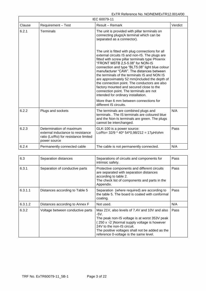
6.2.1 Terminals The unit is provided with pillar terminals on connecting plugs(A terminal which can be separated as a connector).
The unit is fitted with plug connections for all external circuits IS and non-IS. The plugs are fitted with screw pillar terminals type Phoenix “FRONT MSTB 2,5-5.08” for NON-IS connection and type “BLT5.08” light blue colour manufacturer “CAW”. The distances between the terminals of the terminals IS and NON IS are approximately 52 mm(included the depth of the connection point. The conductors are also factory mounted and secured close to the connection point. The terminals are not intended for ordinary installation.
More than 6 mm between connections for different IS circuits.
6.2.2 Plugs and sockets The terminals are combined plugs and terminals . The IS terminals are coloured blue and the Non-Is terminals are green. The plugs cannot be interchanged.
N/A
6.2.3 Determination of maximum external inductance to resistance ratio (Lo/Ro) for resistance limited power source
GLK-100 is a power source: Lo/Ro= 32/9 * 40* 54*0,98/212 = 17µH/ohm
Pass
6.2.4 Permanently connected cable The cable is not permanently connected. N/A
6.3 Separation distances Separations of circuits and components for intrinsic safety.
Pass
6.3.1 Separation of conductive parts Protective components and different circuits are separated with separation distances according to table 2. The check list of components and parts in the Appendix.
Pass
6.3.1.1 Distances according to Table 5 Separation (where required) are according to the table 5. The board is coated with conformal coating.
Pass
6.3.1.2 Distances according to Annex F Not used. N/A
6.3.2 Voltage between conductive parts Max 21V, also levels of 7,4V and 10V and also -5V. The peak non-IS voltage is at worst 353V peak
( 250 x 2 )Normal supply voltage is however 24V to the non-IS circuit. The positive voltages shall not be added as the reference 0-voltage is the same level.
Pass

ExTR Reference No. NO/NEM/ExTR12.0014/00
TRF No. ExTR60079-11_5B-1 Page 4 of 22
IEC 60079-11
Clause Requirement – Test Result – Remark Verdict
6.3.3 Clearance The board and components shall be covered with one layer of insulating coating (conformal coating) The clearance is otherwise 10mm for the Non IS and IS separation and 2 mm for the different IS circuits. Distances to earthed parts may be less than the described distances. Earth of enclosure is connected to the signal earth of the barrier supply voltage.
Pass
6.3.4 Separation distances through casting compound
Applicable to the encapsulated signal transformers. The separation distance is more than 4mm (2mm). The encapsulant of the signal transformer type BYS-1 is PC 5198 polyurethane. CTI tested at least 175
Pass
6.3.5 Separation distances through solid insulation
The solid insulation is at least 1 mm for the non-IS and IS separation (375V peak)Normally 24V
Pass
6.3.6 Composite separations The construction does not include composite separations.
N/A
6.3.7 Creepage distance At least 10mm for the 353V peak level (Non-IS and IS separation). The creepage distances for the IS-circuits are at least 2mm
The CTI of the PC board, terminals and insulating coating is at least CTI 175.
PC-laminate, conformal coating, plastic of terminals, insulation of transformer
Pass
6.3.8 Distance under coating The board shall be coated with one layer applied by machine application(pouring) of conformal coating. The min distance is 3,3 mm for the 250V part and 0,7mm for the 21V part. The coating is Dow -Corning 1-2577 conformal coating (thinned 10% ) . the coating is verified to penetrate under SMD resistors. Dielectric strength 43kV/mm
Pass
6.3.9 Requirements for assembled printed circuit boards
The board is coated with one layer of insulating coating (conformal coating) The coating is Dow -Corning 1-2577 conformal coating Dielectric strength 43kV/mm. The layer is applied with machine application and the coating is thinned by 10%.
Pass
6.3.10 Separation by earth screens Earth screens are not used for separation.
The earthed parts do however separate different parts of the board with different voltages as the earth is common to the different voltage levels.
N/A
6.3.11 Internal wiring The design does not include internal wiring Pass

ExTR Reference No. NO/NEM/ExTR12.0014/00
TRF No. ExTR60079-11_5B-1 Page 5 of 22
IEC 60079-11
Clause Requirement – Test Result – Remark Verdict
6.3.12 Dielectric strength requirement Electric strength test for the isolating transformers was carried out with 1500V AC for 1 minute.
The optocouplers have component certificates and need not be tested.
Pass /Fail
6.3.13 Relays The equipment does not contain switches and relay for connection IS and non-IS circuits.
N/A
6.4 Protection Against Polarity Reversal
The connection terminals are numbered with reference to connection diagram.
Pass
6.5 Earth conductors, connections and terminals
The earth terminals are ordinary pillar terminals for board mounting. The solder pins is soldered in via-holes in the board.
Pass
6.6 Encapsulation Applicable to the encapsulated signal transformers.
The separation distance is more than 4mm (2mm).
The encapsulant of the signal transformer type BYS-1 is PC 5198 polyurethane. CTI tested at least 175
Temp rating: class B (120˚C)
Pass
7 COMPONENTS ON WHICH INTRINSIC SAFETY DEPENDS
7.1 Rating of components Refer to Appendix A.4 for details.
The safety components, resistors and semiconductors (zenerdiodes and thyristors) are rated with a safety factor of at least 1,5 also de-rated to the ambient temperature of
max 80 C . Description of the rating in the Appendix to the test report.
Pass
7.2 Connectors for internal connections, plug-in cards and components
The equipment does not contain internal connectors and plug in cards
N/A

ExTR Reference No. NO/NEM/ExTR12.0014/00
TRF No. ExTR60079-11_5B-1 Page 6 of 22
IEC 60079-11
Clause Requirement – Test Result – Remark Verdict
7.3 Fuses The transformer is protected by means of fuse and resistor. Fuse is 160mA with breaking capacity 1500A according to IEC 127. Serial
resistor 1,5 , 0,6W, 350V, used as current limiters for the fuse.
The zener diodes and thyristors are protected with fuses. The semiconductors are rated according to 6.1 considering 1,7 x In of the fuses and the peak transient current from supply, taking account of Um peak voltage and the infallible serial resistance.
Specification in the Appendix of the test report.
The zener diodes are protected with fuses and series resistors. Resistors are used to limit the current below 1500 A which is the breaking capacity of the fuses. Taking account a 250V Um voltage.
Pass
7.4 Primary and secondary cells and batteries
No cells and battery N/A
7.4.1 General No cells and battery N/A
7.4.2 Electrolyte leakage and ventilation No cells and battery N/A
7.4.3 Cell voltages No cells and battery N/A
7.4.4 Internal resistance of cell or battery
No cells and battery N/A
7.4.5 Batteries in apparatus protected by other means of protection
No cells and battery N/A
7.4.6 Batteries used and replaced in explosive gas atmospheres
No cells and battery N/A
7.4.7 Batteries used but not replaced in explosive gas atmospheres
No cells and battery N/A
7.4.8 External contacts for charging batteries
No cells and battery N/A
7.4.9 Battery construction No cells and battery N/A
7.5 Semiconductors Semiconductors are used as shunt limiting components. The thyristors and zener diodes are constructed to carry the full load current (1,7 times the In of the fuse) and max. transient current with a safety factor of 1,5.Transient absorbing zener diodes are used for absorbing possible let through transients from the thyristors these will not carry a continuous load due to the higher voltage of the thyristors. The max transient current is based on a max. Um of 250 V AC peak and serial resistors in the circuit.(The serial resistance is actually higher as the cold resistance of the fuses are not added)
Pass

ExTR Reference No. NO/NEM/ExTR12.0014/00
TRF No. ExTR60079-11_5B-1 Page 7 of 22
IEC 60079-11
Clause Requirement – Test Result – Remark Verdict
7.5.1 Transient effects The max transient current is based on a max. Um of 250 V AC peak and serial resistors in the circuit.(The serial resistance is actually higher as the cold resistance of the fuses are not added)
Pass
7.5.2 Shunt voltage limiters Three diode links are used in the barrier. Pass
7.5.3 Series current limiters The semiconductors are not used as current limiting devices
N/A
7.6 Failure of components, connections and separations
At least 2mm wide tracks used for the sage track connections
Pass
7.7 Piezo-electric No piezo-electric N/A
7.8 Electrochemical cells for the detection of gases
No electrochemical cells for the detection of gases
N/A
8 INFALLIBLE COMPONENTS, INFALLIBLE ASSEMBLIES OF COMPONENTS AND INFALLIBLE CONNECTIONS ON WHICH INTRINSIC SAFETY DEPENDS
8.1 Mains transformers The transformer is a signal transformer N/A
8.1.1 Protective measures The transformer is protected by means of fuse and resistor. Fuse is 160mA with breaking capacity 1500A according to IEC 127. Serial resistor 1,5 ohm , 0,6W, 350V, used as current limiters for the fuse.
8.1.2 Transformer construction The transformer is type 1A
8.1.3 Transformer type tests The transformer was tested with 1500V AC
The transformer was loaded with 1,7 x 160mA for 6 hours. 60Hz AC and the secondary windings shorted. Voltage adjusted to get 272mA primary current. The heating was neglectable
Insulation is type PPS with 220 °C temp.rating
Pass
8.1.4 Routine test of mains transformers The transformers shall be routine tested with 1500V.
Pass
8.2 Transformers other than mains transformers
The transformers are signal transformers for signal 5Vp-p and 1kHz to 500kHz. The transformers will isolate the circuit from insulation failure to the 250V mains. (Normal supply is 24V).
Pass
8.3 Infallible windings No infallible windings N/A
8.3.1 Damping windings No damping windings N/A
8.3.2 Inductors made by insulated conductors
No inductors made by insulated conductors N/A

ExTR Reference No. NO/NEM/ExTR12.0014/00
TRF No. ExTR60079-11_5B-1 Page 8 of 22
IEC 60079-11
Clause Requirement – Test Result – Remark Verdict
8.4 Current-limiting resistors Current limiting resistors are metal film type and wire wound type. The resistors are not loaded with more than 2/3 of the rated power or voltage See Annex to test report.
Pass
8.5 Blocking capacitors Capacitors are not used as safety blocking capacitors. Capacitors are part of the trigger components of the thyristors . These capacitors(ceramic type) are rated 50V and has 2,3 in safety factor.
N/A
8.6 Shunt safety assemblies Safety shunts are used for transient protection and voltage clamping
Pass
8.6.1 General The diode safety shunts of the board are not separate units, but safety shunt limiters of the interface board for equipment
Pass
8.6.2 Safety shunts N/A
8.6.3 Shunt voltage limiters The zener diodes are protected with fuses and series resistors. Resistors are used to limit the current below 1500 A which is the breaking capacity of the fuses. Taking account a 250V Um voltage.
The resistors of the barrier units are not loaded with more than 2/3 of their rated power according to 7.1
The zener diodes and thyristors are protected with fuses. The semiconductors are rated according to 6.1 considering 1,7 x In of the fuses and the peak transient current from supply, taking account of Um peak voltage and the infallible serial resistance.
Specification in the Appendix of the test report.
The barriers are integrated parts of the interface module.
There are two GND terminals on the board.(2,5 mm2)
The connection of the non-IS and the IS terminals are separated with 50mm clearance.
The components are enclosed in a metal enclosure and not accessible to the exterior of the assembly. The barriers are not separate units but part of the power supply and interface unit
Pass
8.7 Wiring, printed circuit board tracks, and connections
Infallible circuits tracks are at least 2mm wide and the copper track thickness 35 µm . Solder joints in the infallible tracks is 4mm wide.
Pass

ExTR Reference No. NO/NEM/ExTR12.0014/00
TRF No. ExTR60079-11_5B-1 Page 9 of 22
IEC 60079-11
Clause Requirement – Test Result – Remark Verdict
8.8 Galvanically separating components
Pass
8.8.1 General Opto couplers are used to isolate non-intrinsically safe signals from the intrinsically safe signals . The opto isolating circuits are described on sheet 10 and 4. The opto element is separately certified components type CNY 21 EXI (Telefunken) PTB Nr. Ex-90.C.2196U
Pass
8.8.2 Isolating components between intrinsically safe and non-intrinsically safe circuits
Opto couplers V41 to V44 are protected with zeners, fuses and resistors.. Non-IS side: Fuse 20 mA (F41 to F44), zenerdiode 34V, 5W, (1500W peak) 5%(V62 to
V44) , Resistors 1500 2W 5 %, R5 to R8 Diode: (0,02x1,7 x 34 x 1,5 =1,7W (5W) Resistor: (0,02 x 1,7)2 x 1500 x 1,5= 2,6W. Protecting circuit in addition to the above: R60 to R63 (0,1A) V36 to 39 ( 33V, 600W peak), V45 to V49 (80V 1 A). The IS part of the optocouplers is protected
with R42 to R49 (rated 150 1%0,25W) The resistor load is 52 / 150 x 1,5 = 0,25)( 0,25W) The load of the optocouplers will be 5/100 x (7,4-5)= 0,12W the current will be max 50 mA. Sheet 10 :
Non IS part: Fuse 33 mA and 4,7 resistor, diode 34V 5W: Rating: Resistor = (0,033 x 1,7) x 4,7 x 1,5 = 0,022W ( 0,5W). Diode: 0,033 x 1,7 x 34 x 1,5 = 3W (5W). The power to the optocoupler is limited with the Resistors R242, R234 and R236The IS part of the optocoupler:
Resistor R 243 680 1% 0,1W, : power of the resistor 5x1,12 / 680 x 1,5 = 0,066W ( 0,1W) Load of coupler max 30mW Load of coupler V141 : 4,7K 0,1W : 7,42 / 4700 x 1,5 = 0,01W
Pass
8.8.3 Isolating components between separate intrinsically safe circuits
N/A
9 DIODE SAFETY BARRIERS N/A
9.1 General The shunt voltage limiters are designed according to 8.6 being part of a separate module for Level gauge
N/A

ExTR Reference No. NO/NEM/ExTR12.0014/00
TRF No. ExTR60079-11_5B-1 Page 10 of 22
IEC 60079-11
Clause Requirement – Test Result – Remark Verdict
9.2 Construction N/A
9.2.1 Mounting N/A
9.2.2 Facilities for connection to earth There are two GND terminals on the board.(2,5 mm2)
Pass
9.2.3 Protection of components The components are enclosed in a metal enclosure and not accessible to the exterior of the assembly. The barriers are not separate units but part of the power supply and interface unit.
Pass
10 TYPE VERIFICATIONS AND TYPE TESTS
10.1 Spark ignition test Test apparatus according to the IEC 60070-11 was used.
N/A
10.1.1 General Refer to Appendix for details.
Pass
10.1.2 Spark test apparatus According to 60079-11 description N/A
10.1.3, 10.1.3.1, 10.1.3.2
Test gas mixtures and spark test apparatus calibration current
21% H2 was used N/A
10.1.4, 10.1.4.1, 10.1.4.2
Tests with the spark test apparatus – circuit test, safety factors
A minimum safety factor of 1,5. Pass
10.1.5 Testing considerations
10.1.5.1 General The apparatus was calibrated with 30mA, 95mH before and after the tests
Pass
10.1.5.2 Circuits with both inductance and capacitance
Refer to Appendix for details. Pass
10.1.5.3 Circuits using shunt short-circuit (crowbar) protection
Refer to Appendix for details. Pass
10.1.5.4 Results of spark test The circuit passed without ignition. Pass
10.2 Temperature tests
10.3 Dielectric strength tests Voltage test 1500V was carried out for the transformers
Pass
10.4 Determination of parameters of loosely specified components
No such components N/A
10.5 Tests for cells and batteries No battery cell N/A
10.5.1 General N/A
10.5.2 Electrolyte leakage test for cells and batteries
N/A
10.5.3 Spark ignition and surface temperature of cells and batteries
N/A

ExTR Reference No. NO/NEM/ExTR12.0014/00
TRF No. ExTR60079-11_5B-1 Page 11 of 22
IEC 60079-11
Clause Requirement – Test Result – Remark Verdict
10.5.4 Battery container pressure tests N/A
10.6 Mechanical tests N/A
10.6.1 Casting compound Only inside the enclosure and no soft surface of encapsulant.
N/A
10.6.2 Sealing of components before encapsulation
Transformer N/A
10.6.3 Partitions Not used N/A
10.7 Tests for apparatus containing piezoelectric devices
Not used N/A
10.8 Type tests for diode safety barriers and safety shunts
By calculation and assessments. Pass
10.9 Cable pull test Not used N/A
10.10 Transformer tests The transformer was tested with 1500V AC
The transformer was loaded with 1,7 x 160mA for 6 hours. 60Hz AC and the secondary windings shorted. Voltage adjusted to get 272mA primary current. The heating was neglectable
Insulation is type PPS with 220 °C temp.rating
Pass
11 ROUTINE VERIFICATIONS AND TESTS
11.1 Routine tests for diode safety barriers
Pass
11.1.1 Completed barriers The resistors, thyristors and zener shunts shall be tested by Autronica during the construction of the board. Some of the components are specially adjusted to be within the tolerance voltages of the assembly
Pass
11.1.2 Diodes for 2-diode “ia” barriers N/A
11.2 Routine tests for infallible transformers
1500V Pass
12 MARKING
12.1 General According to 60079-0 and additional with safety parameters.
The Um250 V is marked
Pass

ExTR Reference No. NO/NEM/ExTR12.0014/00
TRF No. ExTR60079-11_5B-1 Page 12 of 22
IEC 60079-11
Clause Requirement – Test Result – Remark Verdict
12.2 Marking of connection facilities The output terminals are marked with the terminal numbers X51 and X81. The certificate refers to this marking
Pass
12.3 Warning markings N/A
12.4 Examples of marking
13 DOCUMENTATION Connection diagram. 369897 Pass
ANNEX A ASSESSMENT OF INTRINSICALLY SAFE CIRCUITS (NORMATIVE) Pass
ANNEX B SPARK TEST APPARATUS FOR INTRINSICALLY SAFE CIRCUITS (NORMATIVE)
Pass
ANNEX C MEASUREMENT OF CREEPAGE DISTANCE, CLEARANCES AND SEPARATION DISTANCES THROUGH CASTING COMPOUND AND THROUGH SOLID INSULATION (INFORMATIVE)
ANNEX D ENCAPSULATION (INFORMATIVE)
ANNEX E ENCAPSULATION (INFORMATIVE)
ANNEX F ALTERNATIVE SEPARATION DISTANCES FOR ASSEMBLED PRINTED CIRCUIT BOARDS AND SEPARATION OF COMPONENTS (NORMATIVE)
F.1 General N/A
F.2 Control of pollution access N/A
F.3 Distances for printed circuit boards and separation of components
N/A
F.3.1 Level of protection “ia” and “ib” N/A
F.3.2 Level of protection “ic” N/A

ExTR Reference No. NO/NEM/ExTR12.0014/00
TRF No. ExTR60079-11_5B-1 Page 13 of 22
Measurement Section, including Additional Narrative Remarks APPENDIX A: Description of product
The GLK-100 Level Gauging Processing Unit comprises an intrinsically safe power supply and signal communication lines for a Level Gauging Sensor and additionally four intrinsically safe output circuits for pressure/temperature sensors. The GLK-100 unit is a part of a complete level gauging system and intended for use in ships
A.1 General overview
Output for Level Radar, Terminals X81
Power Supply, Terminals X81:2-1
Maximum output voltage UO=15,6 V
Maximum output current IO=397 mA
Maximum output power PO=2,1 W
Maximum external capacitance CO=497 nF
Maximum external inductance LO=40 H
Maximum ratio LO/RO LO/RO =17 H/
Signal Supply, Terminals X81:2-3,-5,-6,-7,-8
Maximum output voltage UO= 7,4 V
Maximum output current IO= 0,8 mA
Maximum output power PO= 1,5 mW
Maximum external capacitance CO= 11,9 F
Maximum external inductance LO=> 1000 mH
Signal Supply, Terminal X81: 2-4
Maximum output voltage UO= 10,5 V
Maximum output current IO= 11,5 mA
Maximum output power PO= 30 mW
Maximum external capacitance CO= 2,4 F
Maximum external inductance LO= 250 mH As the power supply terminals and signal terminals are connected to the same circuitry of the level radar unit the limiting figures to consider is those of the power supply output terminal X81.1
Pressure/Temperature Sensors, Terminals X51, X52, X53, X54
Maximum output voltage UO= 21 V
Maximum output current IO= 147 mA
Maximum output power PO= 0,77 W
Maximum external capacitance CO= 188 nF
Maximum external inductance LO= 1,5 mH
Maximum ratio LO/RO LO/RO = 46 H/
Nominal supply power for the non intrinsically safe terminals Un=24V

ExTR Reference No. NO/NEM/ExTR12.0014/00
TRF No. ExTR60079-11_5B-1 Page 14 of 22
Maximum safe voltage for the non intrinsically safe terminals Um=250V AC
Range of Ambient Temperature is Ta= +5 C to+55 C
GLK-100 is to be mounted in a control cabinet, according to the manufacturers instruction document AU-1212, as a part of a level gauging system manufactured and completed by Autronica
GKL-100 may be used togeter with the Level Gauging Sensor GLA100, certificate NEMKO Nr.Ex 12.7032X
Cable connections according to the installation drawing GL-1739.
Cables containing more than one of the intrinsically safe output circuits of the unit must comply with the requirements of IEC 60079-25 type A or B
Output values of the power barrier: Uo= 14V +5%+temp coeff. at 80°C stipulated to 15,6V Maximum output power is calculated with the formula: P = 0,25 x 212 /54 x 0,98=2,1W I0=k= 21/54 x0,98=397 mA The following applies: UO= 15,6 IO= 397mA PO=2,1W LO=40 µH (according to the ignition curves of fig.A6 ( EN50020 1994) CO= 497 nF The values of capacitance and inductance were verified by the use of the spark test apparatus. Intrinsically safe external connections for connection to circuits in the hazardous areas are also shown on sheets 5 and 8: Sheet 5: X51.1 , X52.1, X53.1, X54.1 terminal outlets: : Uo= 21V (thyristor voltage) Io= 21/150x0,95= 147mA Po= 212 /150/0,95/4= 0,77W Co=188 nF Lo=1,5mH X51.2...X54.2: These ou Uo=7,4V (thyristorshunted) Io= 7,4/10000= 0,74mA Po=1,4mW Co=11,9/0,61 µF Lo>1000mH
Uo between two terminals: 14,8V Uo=14,8V (thyristorshunted) Io= 14,8/20000= 0,74mA Po=1,4mW Co=11,9/0,61 µF Lo>1000mH

ExTR Reference No. NO/NEM/ExTR12.0014/00
TRF No. ExTR60079-11_5B-1 Page 15 of 22
Uo= 21 + 7,4 = 28,4V (thyristorshunted) Io= 28,4/10150= 2,8mA Po= 20 mW Co=75 nF Lo>1000mH External outlet terminals described on sheet 8: X 81.1 is the connection of the power supply barrier (15,6V) specified in the report .
Uo=7,4V (thyristorshunted) Io= 7,4/10000= 0,74mA Po=1,4mW Co=11,9 µF Lo>1000mH X81.4 10V external connection: Uo=10,5V Io= 10,5/910= 11,5mA Po= 30mW Co= 2,4 µF Lo =250mH
Separation distances Creepage distance of the resistors 0,1W SMD 805 is 1,2 mm in air. Shall be covered with insulating coating and distance is more than 0,7 mm for voltages up to 30V. Concerns resistors R74 to R77, Separation between 250V part and regulated safe voltage: R220-F104: The separation distance for the components is at least 3,3mm coated and 10mm not coated R221 - F103 The separation distance for the components is at least 3,3mm coated and 10mm not coated F105 R236, The separation distance for the components is at least 3,3mm coated.
F106- R248, The separation distance for the components is at least 3,3mm coated.
F41-F44. The separation distance for the components is at least 3,3mm coated F11 R260, F21 R261: Measured more than 3,3 mm coated distance over these components.
T1 and T2: More than 3,3mm coated distance and 10 mm not coated distance.
21 (18V)Volt level
Requirement: Measured at least 0,7 mm coated. F90- R205-R206 are the limiting components prior to the 14V level and 0,7mm coated spacing is satisfied. 10V Level The level is shunted with 2 zener diodes. The V99 and V100 ( Rated 200mW and loaded max 0,1 x 1,5= 0,15W) is clamping this level and this duplicated shunt is infallible. The power accessible from 21 is 0,1W Distance between the tracks of +10V and +18V and -5V is separated with 0,7 mm between the 18V 10V and -5V. The distance between the via-pads and the tracks is measured down to at least 0,7 mm and also safe. The distance between these circuits and other is at least 0,7 mm . The distance between the 21V and other circuits are infallible (Except to the +5V, which is the thyristor circuit and designed to shunt also the 21V power supply. Separation of 10 V, 21 and + 5V(7,4)

ExTR Reference No. NO/NEM/ExTR12.0014/00
TRF No. ExTR60079-11_5B-1 Page 16 of 22
Current limiting output resistors for IS signals.
Distances of current limiting resistors of the external connections:
Requirement 0,7mm coated or 2mm not coated.
Of sheet 5: R70: At least 0,7 mm coated. R74:SMD Resistor are coated, coating has penetrated underneath(1,3mm length between pads) R71: At least 0,7 mm coated. R75: SMD Resistor are coated, coating has penetrated underneath(1,3mm length between pads) R72: At least 0,7 mm coated. R76: SMD Resistor are coated, coating has penetrated underneath(1,3mm length between pads) R73: At least 0,7 mm coated. R77: SMD Resistor are coated, coating has penetrated underneath(1,3mm length between pads) Of sheet 8: R183: SMD Resistor is coated, coating has penetrated underneath(1,3mm length between pads) R140 SMD Resistor is coated, coating has penetrated underneath(1,3mm length between pads) R141 SMD Resistor is coated, coating has penetrated underneath(1,3mm length between pads) R142 SMD Resistor is coated, coating has penetrated underneath(1,3mm length between pads) R143 SMD Resistor is coated, coating has penetrated underneath(1,3mm length between pads) R187: At least 0,7 mm coated R188: At least 0,7 mm coated
A.2 Spark ignition consideration A.2.1 Resistive spark ignition.
The resistive test was done with capacitance added. Current was 397mA x 1,5 and capacitance 615 F Passed 2,5 + 2,5 minutes without ignition. (IIC) A.2.2 Inductive spark ignition. The circuit with 397mA x 1,5 and 40 µH passed the test without ignition during the 2,5 + 2,5 minutes. A.2.3 Capacitive spark ignition. The capacitive test was done with 14,7V x 1,5 and 615 µF without ignition during 2,5 + 2,5 minutes. (The figures were later altered to 15,6V and 497nF, but test was not repeated as the figures were according to the ignition curves of the standard). A.2.4 Combination of inductive and capacitive spark ignition. Not performed for power sources.
A.2.5 Shunt short-circuit (crowbar) spark ignition Thyristors TIC 126, of Texas instruments. A load test of the thyristors has been carried out with current load (0,5 + 0,8A) x 1,7 x 1,5 and a
temperature rise of 30 C has been measured. This will permit a Ta of 80 C and not exceed the 110 C temperature limit. Heat sink is bonded to the thyristors to provide heat transfer.
The max peak current to the thyristor is 250 x 2 /( 3,6 x 0,95) + 250 x 2 /( 2,7 x 0,95)= 241 A The thyristor is rated 100A for 10mS and 316A for a period less the 0,1ms.
The thyristor is rated 400V and above the max peak voltage 250v x 2 . Transient load to the thyristors is limited by the resistors R220, R221.

ExTR Reference No. NO/NEM/ExTR12.0014/00
TRF No. ExTR60079-11_5B-1 Page 17 of 22
The components in the trigger network of the thyristors may be loaded:
V 103 - V 105 , 5W 55, 19V in series with R208( 0,1W 470 ) and R201( 47 0,1W ). V95 5,6V 0,2W
V103: (21 -19)/ 47= 53mA , P = 19x 0,053 x 1,5 = 1,5W V 95: ( 7,4-5,6)/47 = 28mA, P= 5,6 x 0,028 x 1,5 = 0,2W ( 0,2W)
Resistors: 47 x 0,0532 x 1,5 = 0,198W
Resistor 470 2,52 / 470=0,013W
V115 to V117- protected with fuse 0,8A and resistor 5,6 . : Max continous load 0,8 x 1,7 x 1,5 = 2,04A Transient load: The diodes are rated 200A in a half period.
Other shunt diodes: V 4 and V5 : Load 0,033 x 34 x 1,05 x 1,5 = 1,8 W (5W) V75 to V78 . max load (21-10)/150 x 10 x 1,5 = 1,15W (1,5)
A.2.6 Other spark ignition considerations The circuits were tested due to the non- linear characteristics. A.3 Thermal ignition consideration A.3.1 Temperature for small components Associated apparatus. A.3.2 Wiring within apparatus Associated apparatus. A.3.3 Tracks on printed circuit boards Associated apparatus and not subject to temperature classification. A.4 Rating of components A.4.1 Resistors
Load of infallible current limiting resistors(EN 50020 clause 6.1).
A safety factor 1,5 is included in the calculations.
R200. P= 21
2 / 1200 x 1,5 = 0,577W ( 0,6W)
R220 : Pmax= 3,6 x 1,05 x 0,5x1,72 x 1,5 =4,09W (4W)
R221: Pmax = 1,5 x 1,05 x 0,8x1,72 x 1,5 = 4,36 (4W)
R221a: Pmax = 1,2 x 1,05 x 0,8x1,72 x 1,5 = 3,49 (4W)
R205 and R206: Pmax = (0,16A x 1,7)2 x 27 1,05 x 1,5 = 3,05W (4W)
R200: 212 /1200 x 1,5 =0,58W ( 0,6W)
R237, R238 : (0,033 x 1,7)2 x 4,7 x 1,05 x 1,5 = 0,023W (2W)
R70-R73: The resistors are fused 50 mA: P= (0,05 x 1,7)2 x 150 x 1,5 = 1,7 W (2W)
10k resistors R5 to R8: P = ( 0,02 x 1,7)
2 x1500 x 1,5 = 2,6W ( 2W)
R183: 10K: P= 7,42 /10000= 5,5mW
R200: 212 /1000x1,5= 0,69W (0,6W)
R187 og189 : 21/ 1900=0,0113A, P=0,01132 x910=0,116W
A.4.2 Shunt voltage limiters

ExTR Reference No. NO/NEM/ExTR12.0014/00
TRF No. ExTR60079-11_5B-1 Page 18 of 22
Zenerdiodes V107 to V109:
Uz = 14 V 5% 5W .Max voltage to the shunt is 21 from the “three-plicated” thyristor shunt. Max diff. voltage is 21 - 14 x 0,95 = 21 -13,3 = 7,7 V Max power is then Pz= (7,7 /(27 x 2 x 0,98)) x 14 x 0,95 x 1,5 = 2,9W
Load test with 3,4W measured T= 92.2 C on the soldering pin close to the body of the diode. (The load figure was reduced later on, after the test had been carried out) Transient load: These zenerdiodes(14V) shall not be subjected to transient loads due to the transient absorbing diodes V119 to V121 These diodes are rated 1500W The transient current is limited by the fuse F104 and resistor R220.
Max current is 250 x 2 /( 3,6 x 0,95) = 103A. The transient load of the diodes is P= 69,6A x 20 V = 1392W in less than 1 ms. The diodes V119 to V121 shall be verified by the manufacturer to have a higher cut voltage than the thyristors and will only lead possible voltage peaks during the operation time 1 µs of the thyristors...
The transient is the peak let through energy from the thyristors which is about the same as the short circuit current of the fuse and resistor in the pre-arcing period. The diodes V119 to V121 will short any reverse voltage to the thyristors.
Transient load for 8V diodes V123 to V125 250 x 2 /( 3,6 x 0,95)= 103A
A.4.3 Series current limiter Not used A.4.4 _Optocoupler assessments. Opto couplers: Opto couplers are used to isolate non-intrinsically safe signals from the intrinsically safe signals . The opto isolating circuits are described on sheet 10 and 4 of the schematics. The opto element is separately certified components type CNY 21 EXI (Telefunken) PTB Nr. Ex-90.C.2196U. Sheet 4: Opto couplers V41 to V44 are protected with zeners, fuses and resistors.. Non-IS side: Fuse 20 mA (F41 to F44), zenerdiode 34V, 5W, (1500W peak) 5%(V62 to V44) , Resistors 1500 Ω 2W 5 %, R5 to R8 Diode: (0,02x1,7 x 34 x 1,5 =1,7W (5W) Resistor: (0,02 x 1,7)2 x 1500 x 1,5= 2,6W. Protecting circuit in addition to the above: R60 to R63 (0,1A) V36 to 39 ( 33V, 600W peak), V45 to V49 (80V 1 A). The IS part of the optocouplers is protected with R42 to R49 (rated 150 Ω 1%0,25W) The resistor load is 52 / 150 x 1,5 = 0,25)( 0,25W) The load of the optocouplers will be 5/100 x (7,4-5)= 0,12W the current will be max 50 mA. Sheet 10 : Non IS part: Fuse 33 mA and 4,7 ohm resistor, diode 34V 5W: Rating: Resistor = (0,033 x 1,7) x 4,7 x 1,5 = 0,022W ( 0,5W). Diode: 0,033 x 1,7 x 34 x 1,5 = 3W (5W). The power to the optocoupler is limited with the Resistors R242, R234 and R236The IS part of the optocoupler: Resistor R 243 680 ohm1% 0,1W, : power of the resistor 5x1,12 / 680 x 1,5 = 0,066W ( 0,1W) Load of coupler max 30mW Load of coupler V141 : 4,7K 0,1W : 7,42 / 4700 x 1,5 = 0,01W

ExTR Reference No. NO/NEM/ExTR12.0014/00
TRF No. ExTR60079-11_5B-1 Page 19 of 22
A.4.5 Isolating transformers
Infallible galvanic separation of transformers
Infallible isolating transformers Transformer is according to type 1A Transformers are protected with fuses and resistors. Load of resistors: R260 and R261: Fuses F11 and F21 rated 0,16A: P = (0,16 x 1,7 )
2 x 1,6 = 0,17W
Max current is 250V / 1,6 = 156A. Fuses with high breaking capacity (1500A) are used. Voltage rating 350V The transformer was tested with 1,7 x 160 mA load and frequency 100 kHz.
Max temp was 58 K. Temp rating of insulating materials of transformer at least 220 C Max output load is limited by the resistors R11, R12, R13, R21, R22, R23 Rated only 0,1W R13 and R23 47K P = 7,4
2 / 47000 x 1,5= 0,001
The output is shunted with the diodes V1-V6 and V11 to V16. Diodes rated 9V, 1,5W and 5%,600W transient load. The diodes will shunt any transient signals in the secondary circuit of the transformer. The diodes will not be loaded from other supplying circuits than the transformer. The nominal output voltage of the transformer is 2,5V p-p. The transformer will not be capable of supplying a 50-60 Hz signal. This was verified by testing and measurement.
A.4.6
Assessment of the fuses
F104, 0,5A , R220, 3,6 Imax = 250/3,6 (5%) = 73 Amp, Breaking capacity:
F103, 0,8A , R221A,B, 2,7 Imax = 250/2,7 (5%) = 92,6 Amp, Breaking capacity:
F105, F106, 32mA , R237, R248, 4,7 : Imax= 56 A, Breaking capacity: 800A
F11, F21, 160 mA, R260, R261, 1,5 , Imax = 175 A, Breaking capacity: 800A
F41...F44, 20 mA , R5...R8, 4,7 Imax = 56A, Breaking capacity: 800A

ExTR Reference No. NO/NEM/ExTR12.0014/00
TRF No. ExTR60079-11_5B-1 Page 20 of 22
APPENDIX B: Tests Option 1: If tests records are provided as an attachment, please complete the following table:
Document number Number of Pages Name of Tests
Option 2: If tests records are not provided as an attachment, please complete the following table: B.1 Test conducted
Equipment Tested:
Date of Test (yyyy/mm/dd):
Clause and Standards:
B.1.1 Test procedures The transformer was tested with 1500V AC for one minute between the primary and secondary winding. B.1.2 Results
There was no flashover or insulation break down during the test.
B.2 Test conducted
Equipment Tested: transformer
Date of Test (yyyy/mm/dd): 1997-10-22
Clause and Standards: Clause 8-1
B.2.1 Test procedures
Infallible isolating transformers Transformer is according to type 1A Transformers are protected with fuses and resistors. Load of resistors: R260 and R261: Fuses F11 and F21 rated 0,16A: P = (0,16 x 1,7 )2 x 1,6 = 0,17W Max current is 250V / 1,6 = 156A. Fuses with high breaking capacity (1500A) are used. Voltage rating 350V The transformer was tested with 1,7 x 160 mA load and frequency 100 kHz.
Max temp was 58 K. Temp rating of insulating materials of transformer at least 220 C Max output load is limited by the resistors R11, R12, R13, R21, R22, R23 Rated only 0,1W R13 and R23 47K P = 7,42 / 47000 x 1,5= 0,001
B.3.2 Results
Insulation temperature was max 138 C @Ta. 80 C(55 C) and < 220 C
B.3 Test conducted
Equipment Tested: Output circuit of GLK 100 power
Date of Test (yyyy/mm/dd): 1997-10-22
Clause and Standards: 60079-11 clause 10

ExTR Reference No. NO/NEM/ExTR12.0014/00
TRF No. ExTR60079-11_5B-1 Page 21 of 22
B.3.1 Test procedures B.3.1.1 Inductive circuits(L > 1 mH)
The circuit with 397mA x 1,5 and 40 H passed the test without ignition during the 2,5 + 2,5 minutes
B.3.2.1 No ignition occurred, Test gas mixture ignited within <5 sec with calibration circuit connected 3.1.2
Resistive circuits (L < =1 mH)
The resistive test was done with capacitance added. Current was 397mA x 1,5. and capacitance 615 F Passed 2,5 + 2,5 minutes without ignition
B3.2.2 Result No ignition occurred, Test gas mixture ignited within <5 sec with calibration circuit connected B.3.1.3 Capacitive circuits
The capacitive test was done with 14,7V x 1,5 and 615 F without ignition during 2,5 + 2,5 minutes. (The figures were later altered to 15,6V and 497nF, but test was not repeated as the figures were according to the ignition curves of the standard)
B.3.2.3 Result No ignition occurred, Test gas mixture ignited within <5 sec with calibration circuit connected
B4 Test conducted
Equipment Tested: Thyristor TIC 126
Date of Test (yyyy/mm/dd): 1997-10-22
Clause and Standards: 60070-11 clause 7.1
B.4.1 Test procedures Thyristors TIC 126 of Texas instruments. A load test of the thyristors has been carried out with current load (0,5 + 0,8A) x 1,7 x 1,5 and a
temperature rise of 30 C was measured. This will permit a Ta of 80 C and not exceed the 110 C temperature limit. Heat sink is bonded to the thyristors to provide heat transfer. B.4.2 Results
Temperature rise of 30 C was measured. This will allow a Ta of 80 C/ 55 C and not exceed the 110 C limit for the Tj.

ExTR Reference No. NO/NEM/ExTR12.0014/00
TRF No. ExTR60079-11_5B-1 Page 22 of 22
B 5 Test conducted
Equipment Tested: Opto couplers V41-V44
Date of Test (yyyy/mm/dd): 1997-10-22
Clause and Standards: 60079-11 clause 8.8 and 6.3.12
B.6.1 Test procedures Dielectric strength test of opto-couplers tested with 1500V for 1 minute between sender and receiver circuits. B.5.2 Results
The was no flashover or insulation breakdown during the tests.