
Extent of the Warranty - Leybold Online Shop...TTR 101 N, TTR 101 N S Operating Manual...
42
1 300544655_002_C1 - 11/2016 - © Leybold THERMOVAC Transmitter TTR 101 N, TTR 101 N S Operating Manual 300544655_002_C1 Part Numbers: 230350V02 230351V02 230352V02 230353V02 230354V02 230355V02 230356V02 230366V02 230702V02
Transcript of Extent of the Warranty - Leybold Online Shop...TTR 101 N, TTR 101 N S Operating Manual...

1 300544655_002_C1 - 11/2016 - © Leybold
THERMOVAC Transmitter TTR 101 N, TTR 101 N S Operating Manual 300544655_002_C1 Part Numbers: 230350V02
230351V02
230352V02
230353V02
230354V02
230355V02
230356V02
230366V02
230702V02
2 300544655_002_C1 - 11/2016 - © Leybold
Contents
Safety Information 3 0.1 Symbols used 3 0.2 Personnel Qualifications 3 0.3 General safety information 3 0.4 Liability and Warranty 5
Unpacking 6 Description 7
2.1 Technical Data 8 2.2 Dimensions 10 2.3 Accessories and replacement part numbers 12
Transmitter Installation (Mechanical) 13 3.1 Conforming utilization 13 3.2 Non-conforming utilization 13 3.3 Process compatibility 13 3.4 Vacuum connections 14
Transmitter Installation (Electrical) 15 4.1 Input/Output Wiring 16 4.2 Setpoint relays 18
Operations 20 5.1 Pressure output 20 5.2 Analog output 21 5.3 Sensor gas dependence 23
Functions 24 6.1 LED-ring/LED status indicator 24 6.2 Vacuum-zero adjustments and setpoint adjustments 25 6.3 User switch adjustments 27 6.4 Integrated touch display 31
FAQ (Frequently Asked Questions) 33 Trouble shooting 35 Maintenance 36
9.1 Transmitter maintenance: installation of replacement parts 36 Declaration of Contamination 38 Declaration of Conformity 40 Notes 41 Sales and Service 42
3 300544655_002_C1 - 11/2016 - © Leybold
Safety Information
0.1 Symbols used The first two symbols identify other information in this manual that is essential or useful in achieving optimal performance from the transmitter. The last symbol below is used throughout this manual to further define the safety concerns associated with the product.
Calls attention to important procedures, practices or conditions.
0.2 Personnel Qualifications
0.3 General safety information
The safety instructions should always be followed during installation and operation of the transmitter. Pass safety information to all users.
Adhere to the applicable regulations and take the necessary precautions for the process media used. Consider possible reactions between the materials and the process media. Consider possible reactions (e.g. explosion) of the process media due to the heat generated by the product.
Adhere to the applicable regulations and take the necessary precautions for all work you are going to do and consider the safety instructions in this document.
Before beginning to work, find out whether any vacuum components are contaminated. Adhere to the relevant regulations and take the necessary precautions when handling contaminated parts.
Safety Precautions:
Failure to read message could result in damage to the equipment.
Refer to manual. Failure to read message could result in personal injury or serious damage to the equipment or both.
All work described in this document may only be carried out by persons who have suitable technical training and the necessary experience or who have been instructed by the end-user of the product.
Explosive Environments. Do not use the transmitter in presence of flammable gases or other explosive environments.
Corrosive Environments. The transmitter is not intended for use in corrosive environments. Refer to Transmitter installation chapter 4 of this manual.
Critical
Attention
Critical
!
!
Caution !
Skilled personnel
4 300544655_002_C1 - 11/2016 - © Leybold
Service and Repair. Do not substitute parts or modify instrument other than described in chapter 9. Do not install substituted parts or perform any unauthorized modification to the instrument. Return the instrument to a Leybold Calibration and Service Center for service and repair to ensure all of the safety features are maintained.
DANGER: contaminated parts Contaminated parts can be detrimental to health and environment. Before beginning to work, find out whether any parts are contaminated. Adhere to the relevant regulations and take the necessary precautions when handling contaminated parts. If you need further support please contact Leybold.
Caution: vacuum component Dirt and damages impair the function of the vacuum component. When handling vacuum components, take appropriate measures to ensure cleanliness and prevent damages.
CE marking The transmitter complies with European standards for CE marking. Refer to Declaration of Conformity chapter - of this manual.
Fuse. The transmitter power supply input has an internal thermal fuse. The fuse is self-recoverable and should not be changed.
Electrical connections. The transmitter must be properly electrically connected in order to perform according to the specifications. Output pins are not protected against wrong electrical connections. Wrong electrical connections can cause permanent damage to the transmitter or interference to measuring performance. Refer to electrical connections description in chapter 4 of this manual.
Caution: dirt sensitive area Touching the product or parts thereof with one's bare hands increases the desorption rate. Always wear clean, lint-free gloves and use clean tools when working in this area.
Critical
!
!
!
Caution !
Caution !
Critical
!
Attention !
!
Attention !
Caution !

5 300544655_002_C1 - 11/2016 - © Leybold
0.4 Liability and Warranty
Leybold assumes no liability and the warranty becomes null and void if the end-user or third parties
disregard the information in this document
use the product in a non-conforming manner
make any kind of interventions (modifications, alterations etc.) on the product
use the product with accessories not listed in the product documentation The end-user assumes the responsibility in conjunction with the process media used. Transmitter failures due to contamination are not covered by the warranty.

6 300544655_002_C1 - 11/2016 - © Leybold
Unpacking
Before unpacking your transmitter, check all surfaces of the packing material for shipping damage. Inspect for visible damage. If found, notify the carrier immediately. Please be sure that your transmitter package contains these items:
1 pcs. TTR 101 N THERMOVAC Transmitter
1 pcs. English short form manual (P/N: 300544668_002)
1 pcs. German short form manual (P/N: 300544668_001)
1 pcs. Product Inspection and Test Report
1 pcs. Pin for adjusting settings via button (only for P/N: 230350V02, 230351V02, 230352V02, 230353V02, 230354V02, 230355V02, 230356V02, 230366V02)
If any items are missing, please contact Leybold.
7 300544655_002_C1 - 11/2016 - © Leybold
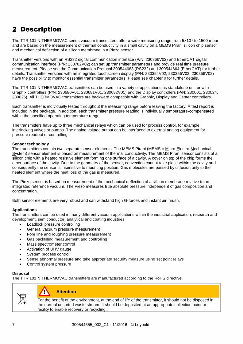
Description
The TTR 101 N THERMOVAC series vacuum transmitters offer a wide measuring range from 5×10⁻⁵ to 1500 mbar and are based on the measurement of thermal conductivity in a small cavity on a MEMS Pirani silicon chip sensor and mechanical deflection of a silicon membrane in a Piezo sensor. Transmitter versions with an RS232 digital communication interface (P/N: 230366V02) and EtherCAT digital communication interface (P/N: 230702V02) can set up transmitter parameters and provide real time pressure measurement. Please see the Communication Protocol 300544663 (RS232) and 300544664 (EtherCAT) for further details. Transmitter versions with an integrated touchscreen display (P/N: 230354V02, 230355V02, 230356V02) have the possibility to monitor essential transmitter parameters. Please see chapter 0 for further details. The TTR 101 N THERMOVAC transmitters can be used in a variety of applications as standalone unit or with Graphix controllers (P/N: 230680V01, 230681V01, 230682V01) and the Display controllers (P/N: 230001, 230024, 230025). All THERMOVAC transmitters are backward compatible with Graphix, Display and Center controllers. Each transmitter is individually tested throughout the measuring range before leaving the factory. A test report is included in the package. In addition, each transmitter pressure reading is individually temperature-compensated within the specified operating temperature range. The transmitters have up to three mechanical relays which can be used for process control, for example interlocking valves or pumps. The analog voltage output can be interfaced to external analog equipment for pressure readout or controlling. Sensor technology The transmitters contain two separate sensor elements. The MEMS Pirani (MEMS = Micro-Electro-Mechanical-System) sensor element is based on measurement of thermal conductivity. The MEMS Pirani sensor consists of a silicon chip with a heated resistive element forming one surface of a cavity. A cover on top of the chip forms the other surface of the cavity. Due to the geometry of the sensor, convection cannot take place within the cavity and consequently the sensor is insensitive to mounting position. Gas molecules are passed by diffusion only to the heated element where the heat loss of the gas is measured. The Piezo sensor is based on measurement of the mechanical deflection of a silicon membrane relative to an integrated reference vacuum. The Piezo measures true absolute pressure independent of gas composition and concentration. Both sensor elements are very robust and can withstand high G-forces and instant air inrush. Applications The transmitters can be used in many different vacuum applications within the industrial application, research and development, semiconductor, analytical and coating industries:
Loadlock pressure controlling
General vacuum pressure measurement
Fore line and roughing pressure measurement
Gas backfilling measurement and controlling
Mass spectrometer control
Activation of UHV gauge
System process control
Sense abnormal pressure and take appropriate security measure using set point relays
Control system pressure Disposal The TTR 101 N THERMOVAC transmitters are manufactured according to the RoHS directive.
For the benefit of the environment, at the end of life of the transmitter, it should not be disposed in the normal unsorted waste stream. It should be deposited at an appropriate collection point or facility to enable recovery or recycling.
Attention !
8 300544655_002_C1 - 11/2016 - © Leybold
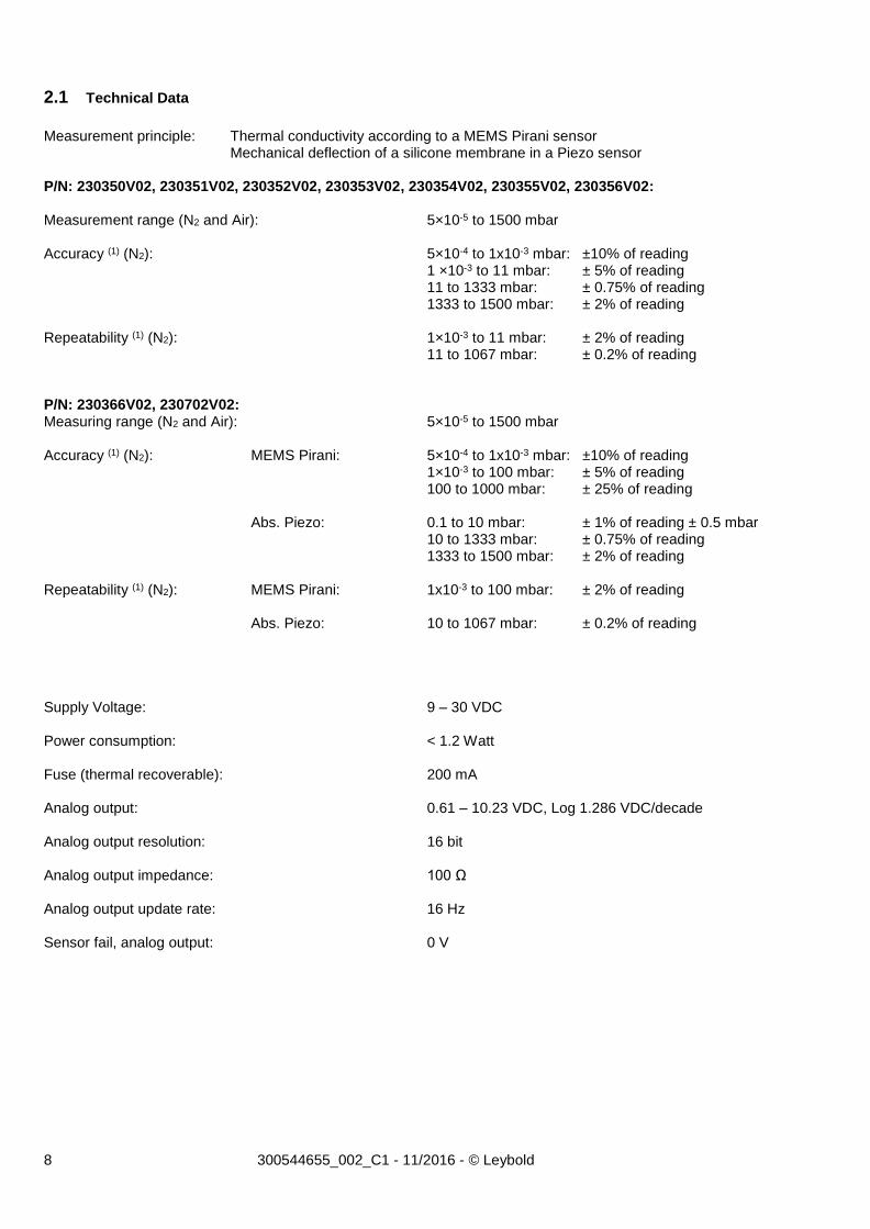
2.1 Technical Data
Measurement principle: Thermal conductivity according to a MEMS Pirani sensor Mechanical deflection of a silicone membrane in a Piezo sensor P/N: 230350V02, 230351V02, 230352V02, 230353V02, 230354V02, 230355V02, 230356V02: Measurement range (N2 and Air): 5×10⁻⁵ to 1500 mbar Accuracy (1) (N2): 5×10⁻⁴ to 1x10⁻³ mbar: ±10% of reading 1 ×10⁻³ to 11 mbar: ± 5% of reading 11 to 1333 mbar: ± 0.75% of reading 1333 to 1500 mbar: ± 2% of reading Repeatability (1) (N2): 1×10⁻³ to 11 mbar: ± 2% of reading 11 to 1067 mbar: ± 0.2% of reading P/N: 230366V02, 230702V02: Measuring range (N2 and Air): 5×10⁻⁵ to 1500 mbar Accuracy (1) (N2): MEMS Pirani: 5×10⁻⁴ to 1x10⁻³ mbar: ±10% of reading 1×10⁻³ to 100 mbar: ± 5% of reading 100 to 1000 mbar: ± 25% of reading Abs. Piezo: 0.1 to 10 mbar: ± 1% of reading ± 0.5 mbar 10 to 1333 mbar: ± 0.75% of reading 1333 to 1500 mbar: ± 2% of reading Repeatability (1) (N2): MEMS Pirani: 1x10⁻³ to 100 mbar: ± 2% of reading Abs. Piezo: 10 to 1067 mbar: ± 0.2% of reading Supply Voltage: 9 – 30 VDC Power consumption: < 1.2 Watt Fuse (thermal recoverable): 200 mA Analog output: 0.61 – 10.23 VDC, Log 1.286 VDC/decade Analog output resolution: 16 bit Analog output impedance: 100 Ω Analog output update rate: 16 Hz Sensor fail, analog output: 0 V
9 300544655_002_C1 - 11/2016 - © Leybold
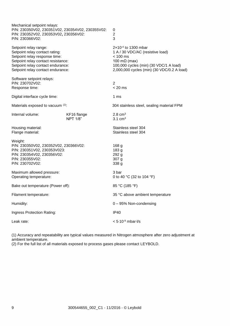
Mechanical setpoint relays: P/N: 230350V02, 230351V02, 230354V02, 230355V02: 0 P/N: 230352V02, 230353V02, 230356V02: 2 P/N: 230366V02: 3 Setpoint relay range: 2×10⁻⁴ to 1300 mbar Setpoint relay contact rating: 1 A / 30 VDC/AC (resistive load) Setpoint relay response time: < 100 ms Setpoint relay contact resistance: 100 mΩ (max) Setpoint relay contact endurance: 100,000 cycles (min) (30 VDC/1 A load) Setpoint relay contact endurance: 2,000,000 cycles (min) (30 VDC/0.2 A load) Software setpoint relays: P/N: 230702V02: 2 Response time: < 20 ms Digital interface cycle time: 1 ms Materials exposed to vacuum (2): 304 stainless steel, sealing material FPM Internal volume: KF16 flange 2.8 cm3 NPT 1/8” 3.1 cm3 Housing material: Stainless steel 304 Flange material: Stainless steel 304 Weight: P/N: 230350V02, 230352V02, 230366V02: 168 g P/N: 230351V02, 230353V023: 183 g P/N: 230354V02, 230356V02: 292 g P/N: 230355V02: 307 g P/N: 230702V02: 338 g Maximum allowed pressure: 3 bar Operating temperature: 0 to 40 °C (32 to 104 °F) Bake out temperature (Power off): 85 °C (185 °F) Filament temperature: 35 °C above ambient temperature Humidity: 0 – 95% Non-condensing Ingress Protection Rating: IP40
Leak rate: < 5∙10-9 mbar∙l/s
(1) Accuracy and repeatability are typical values measured in Nitrogen atmosphere after zero adjustment at ambient temperature. (2) For the full list of all materials exposed to process gases please contact LEYBOLD.
10 300544655_002_C1 - 11/2016 - © Leybold
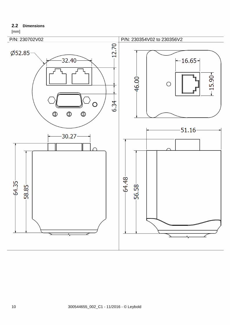
2.2 Dimensions
[mm]
P/N: 230702V02 P/N: 230354V02 to 230356V2
11 300544655_002_C1 - 11/2016 - © Leybold
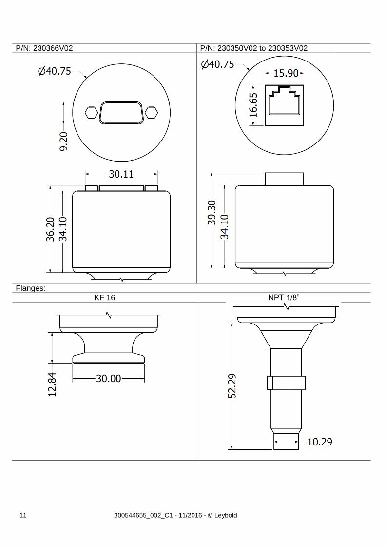
P/N: 230366V02 P/N: 230350V02 to 230353V02
Flanges:
KF 16 NPT 1/8”
12 300544655_002_C1 - 11/2016 - © Leybold
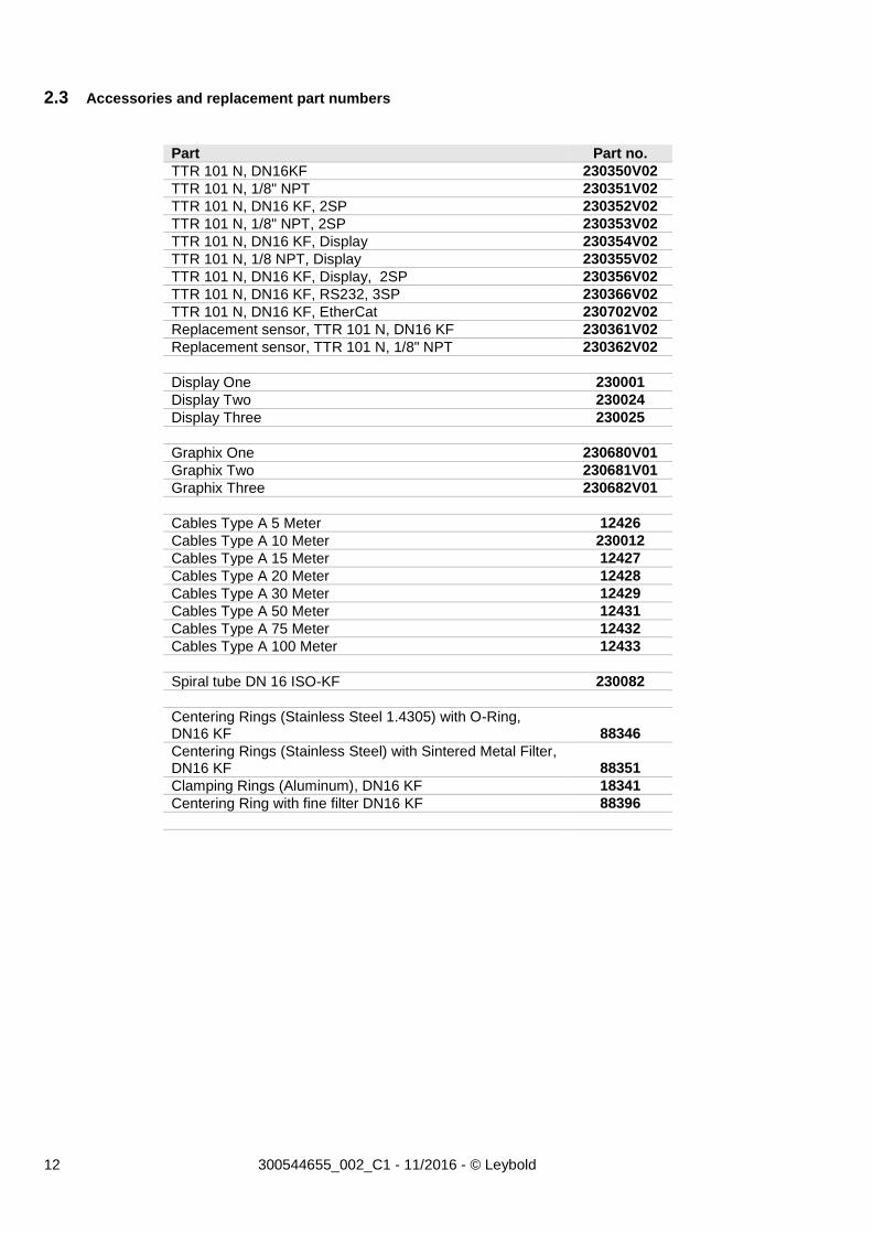
2.3 Accessories and replacement part numbers
Part Part no.
TTR 101 N, DN16KF 230350V02
TTR 101 N, 1/8" NPT 230351V02
TTR 101 N, DN16 KF, 2SP 230352V02
TTR 101 N, 1/8" NPT, 2SP 230353V02
TTR 101 N, DN16 KF, Display 230354V02
TTR 101 N, 1/8 NPT, Display 230355V02
TTR 101 N, DN16 KF, Display, 2SP 230356V02
TTR 101 N, DN16 KF, RS232, 3SP 230366V02
TTR 101 N, DN16 KF, EtherCat 230702V02
Replacement sensor, TTR 101 N, DN16 KF 230361V02
Replacement sensor, TTR 101 N, 1/8" NPT 230362V02
Display One 230001
Display Two 230024
Display Three 230025
Graphix One 230680V01
Graphix Two 230681V01
Graphix Three 230682V01
Cables Type A 5 Meter 12426
Cables Type A 10 Meter 230012
Cables Type A 15 Meter 12427
Cables Type A 20 Meter 12428
Cables Type A 30 Meter 12429
Cables Type A 50 Meter 12431
Cables Type A 75 Meter 12432
Cables Type A 100 Meter 12433
Spiral tube DN 16 ISO-KF 230082
Centering Rings (Stainless Steel 1.4305) with O-Ring, DN16 KF 88346
Centering Rings (Stainless Steel) with Sintered Metal Filter, DN16 KF 88351
Clamping Rings (Aluminum), DN16 KF 18341
Centering Ring with fine filter DN16 KF 88396
13 300544655_002_C1 - 11/2016 - © Leybold
Transmitter Installation (Mechanical)
3.1 Conforming utilization
The transmitter is intended for measuring pressure.
The transmitters are intended for use in relatively clean environments.
The transmitter can only be used by persons who have suitable technical training and the necessary experience or who have been instructed by the end-user of the product.
Always ensure that all vacuum sealing items and surfaces are clean, without damage and free of particles.
Use a cable with strain relief to ensure proper electrical connection and to reduce stress on the connectors.
To comply with EN61326-1 immunity requirements, use a braided, shielded cable.
3.2 Non-conforming utilization
The transmitter cannot be used for measurements other than described in this manual.
The transmitters are not intended for use in dirty and corrosive environments
Do not use the transmitter in presence of flammable gases or other explosive environments.
Do not install substituted parts or perform any unauthorized modification to the instrument.
The transmitter is not intended for use above maximum allowed pressure.
3.3 Process compatibility
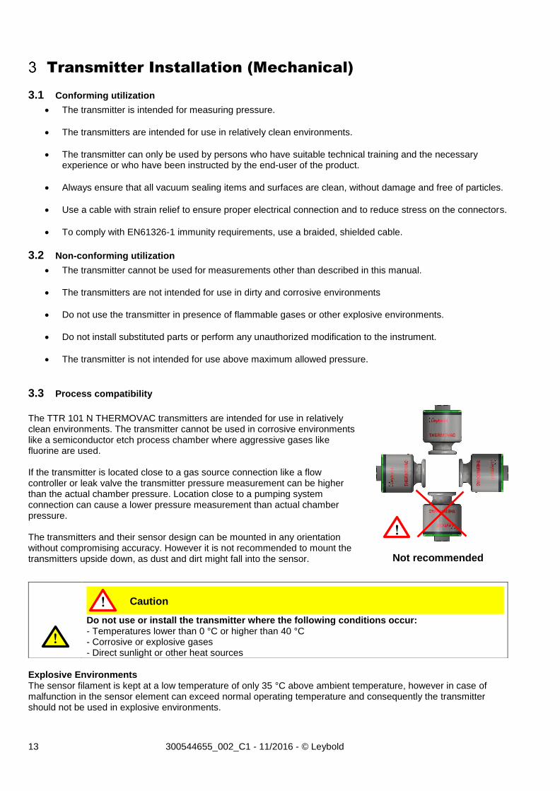
The TTR 101 N THERMOVAC transmitters are intended for use in relatively clean environments. The transmitter cannot be used in corrosive environments like a semiconductor etch process chamber where aggressive gases like fluorine are used. If the transmitter is located close to a gas source connection like a flow controller or leak valve the transmitter pressure measurement can be higher than the actual chamber pressure. Location close to a pumping system connection can cause a lower pressure measurement than actual chamber pressure. The transmitters and their sensor design can be mounted in any orientation without compromising accuracy. However it is not recommended to mount the transmitters upside down, as dust and dirt might fall into the sensor.
Explosive Environments The sensor filament is kept at a low temperature of only 35 °C above ambient temperature, however in case of malfunction in the sensor element can exceed normal operating temperature and consequently the transmitter should not be used in explosive environments.
Do not use or install the transmitter where the following conditions occur: - Temperatures lower than 0 °C or higher than 40 °C - Corrosive or explosive gases - Direct sunlight or other heat sources
!
Not recommended
Caution !
!
14 300544655_002_C1 - 11/2016 - © Leybold
Temperature The transmitter has an active and individual sensor temperature compensation circuit that ensures accurate measurement in a wide temperature range. For best measuring performance avoid large temperature gradients and direct cooling like air-condition air stream or heating like a pump exhaust stream. Bake out The transmitter electronics can withstand maximum 85 °C (185 °F) when the power is turned off. Contamination Locate and orient the transmitter where contamination is least likely. The sensor has a low filament temperature of only 35 °C above ambient temperature; therefore, the sensor is less prone to contamination by cracking products from fore vacuum pump oil.
Vibrations and instant air inrush The sensor elements are extremely robust to mechanical forces like vibration and G-forces. The sensor element cannot be damaged by fast and repeated pressure cycles or instant inrush of air.
3.4 Vacuum connections
The transmitters are available with different types of vacuum fittings. When mounting the transmitter, always ensure that all vacuum sealing items and surfaces are clean, without damage and free of particles. Do not touch the vacuum flange sealing surface.
Pressure range The standard TTR 101 N THERMOVAC transmitter are internally sealed with elastomer FPM sealing and is intended for use in the pressure range 5×10⁻⁵ to 1500 mbar. If used in UHV applications the out gassing rate of FPM can be too high.
If the transmitter is backfilled with a liquid like pump oil the sensor element is likely permanently damaged. The transmitter cannot be cleaned using solvents.
If the transmitter will be exposed to pressures above atmospheric pressure make sure that proper vacuum fittings are used. Ensure that the internal system pressure is at ambient pressure conditions before opening the vacuum system and removing any connections.
Attention
Caution
!
!
!
!
15 300544655_002_C1 - 11/2016 - © Leybold
Transmitter Installation (Electrical)
TTR 101 N THERMOVAC transmitters are available with different input/output connectors. Use a cable with strain relief to ensure proper electrical connection and to reduce stress on the connectors.
To comply with EN61326-1 immunity requirements, use a braided shielded cable. Connect the braid to the metal hoods at both ends of the cable with the end for power supply connected to earth ground. Ground loops, differences of potential, or EMC problems may affect the measurement signal. For optimum signal quality, please do observe the following notes:
Use an overall metal braided shielded cable. The connector must have a metal case.
Connect the cable shield to ground at one side via the connector case. Make sure the connector case has direct contact to the cable's shield on its whole circumference. Do not connect the other side of the shield.
Connect the supply common with protective ground directly at the power.
Use differential measurement input (signal common and supply common conducted separately).
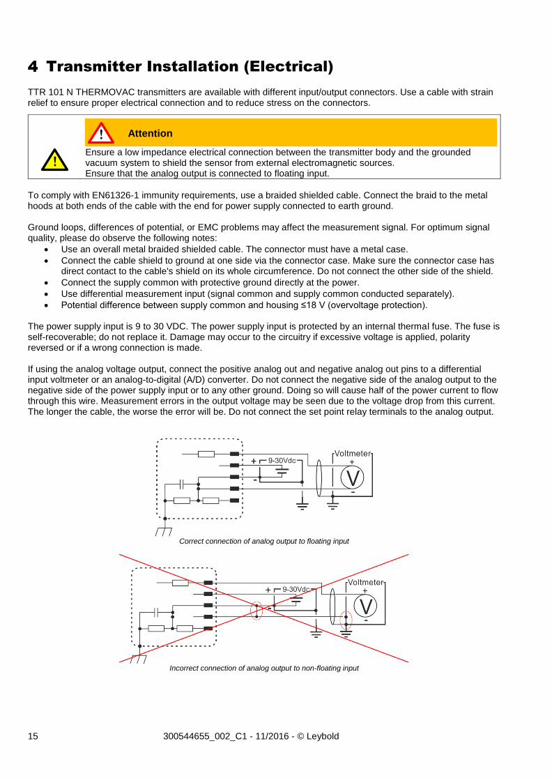
Potential difference between supply common and housing ≤18 V (overvoltage protection). The power supply input is 9 to 30 VDC. The power supply input is protected by an internal thermal fuse. The fuse is self-recoverable; do not replace it. Damage may occur to the circuitry if excessive voltage is applied, polarity reversed or if a wrong connection is made. If using the analog voltage output, connect the positive analog out and negative analog out pins to a differential input voltmeter or an analog-to-digital (A/D) converter. Do not connect the negative side of the analog output to the negative side of the power supply input or to any other ground. Doing so will cause half of the power current to flow through this wire. Measurement errors in the output voltage may be seen due to the voltage drop from this current. The longer the cable, the worse the error will be. Do not connect the set point relay terminals to the analog output.
Correct connection of analog output to floating input
Incorrect connection of analog output to non-floating input
Ensure a low impedance electrical connection between the transmitter body and the grounded vacuum system to shield the sensor from external electromagnetic sources. Ensure that the analog output is connected to floating input.
Attention !
!
16 300544655_002_C1 - 11/2016 - © Leybold
4.1 Input/Output Wiring
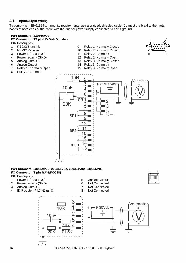
To comply with EN61326-1 immunity requirements, use a braided, shielded cable. Connect the braid to the metal hoods at both ends of the cable with the end for power supply connected to earth ground.
Part Numbers: 230366V02: I/O Connector (15 pin HD Sub D male )
PIN Description 1 RS232 Transmit 9 Relay 1, Normally Closed 2 RS232 Receive 10 Relay 2, Normally Closed 3 Power + (9-30 VDC) 11 Relay 2, Common 4 Power return - (GND) 12 Relay 2, Normally Open 5 Analog Output + 13 Relay 3, Normally Closed 6 Analog Output - 14 Relay 3, Common 7 Relay 1, Normally Open 15 Relay 3, Normally Open 8 Relay 1, Common
Part Numbers: 230350V02, 230351V02, 230354V02, 230355V02: I/O Connector (8 pin RJ45/FCC68)
PIN Description 1 Power + (9-30 VDC) 5 Analog Output - 2 Power return - (GND) 6 Not Connected 3 Analog Output + 7 Not Connected 4 ID-Resistor, 71.5 kΩ (±1%) 8 Not Connected
17 300544655_002_C1 - 11/2016 - © Leybold
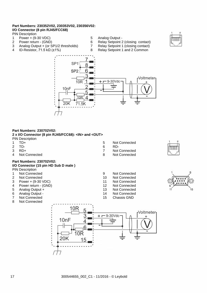
Part Numbers: 230352V02, 230353V02, 230356V02: I/O Connector (8 pin RJ45/FCC68)
PIN Description 1 Power + (9-30 VDC) 5 Analog Output - 2 Power return - (GND) 6 Relay Setpoint 2 (closing contact) 3 Analog Output + (or SP1/2 thresholds) 7 Relay Setpoint 1 (closing contact) 4 ID-Resistor, 71.5 kΩ (±1%) 8 Relay Setpoint 1 and 2 Common
Part Numbers: 230702V02: 2 x I/O Connector (8 pin RJ45/FCC68): <IN> and <OUT>
PIN Description 1 TD+ 5 Not Connected 2 TD- 6 RD- 3 RD+ 7 Not Connected 4 Not Connected 8 Not Connected
Part Numbers: 230702V02: I/O Connector (15 pin HD Sub D male )
PIN Description 1 Not Connected 9 Not Connected 2 Not Connected 10 Not Connected 3 Power + (9-30 VDC) 11 Not Connected 4 Power return - (GND) 12 Not Connected 5 Analog Output + 13 Not Connected 6 Analog Output - 14 Not Connected 7 Not Connected 15 Chassis GND 8 Not Connected
18 300544655_002_C1 - 11/2016 - © Leybold
4.2 Setpoint relays
The TTR 101 N THERMOVAC transmitters have up to three mechanical relays that can be used for controlling external process equipment. The relays have closing and breaking contacts and the contacts are rated 30 VDC, 1 A, resistive load. For the setup of the setpoints, refer to chapter 6. Inductive relay load Special precautions should be taken when driving inductive loads with the relay contact. When an inductive load like a solenoid is energized, the in-rush current is significant higher than the regular load current. In-rush currents exceeding the relay contact rating can cause reduction of relay contact life time or contact reliability. When a solenoid is de-energized, the collapsing magnetic field can cause significant voltage spikes. These spikes can couple capacitively from cable to cable and interfere with measuring electronics or transmitter signal.
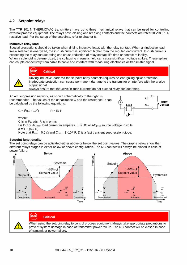
An arc suppression network, as shown schematically to the right, is recommended. The values of the capacitance C and the resistance R can be calculated by the following equations:
C = I2/(1 x 107) R = E/ Ia where: C is in Farads. R is in ohms I is DC or ACpeak load current in amperes. E is DC or ACpeak source voltage in volts a = 1 + (50/ E) Note that Rmin = 0.5 Ω and Cmin = 1×10⁻⁹ F, D is a fast transient suppression diode. Setpoint functionality The set point relays can be activated either above or below the set point values. The graphs below show the different relays stages in either below or above configuration. The NC contact will always be closed in case of power failure.
Driving inductive loads via the setpoint relay contacts requires de-energizing spike protection. Inadequate protection can cause permanent damage to the transmitter or interfere with the analog output signal. Always ensure that inductive in-rush currents do not exceed relay contact rating.
When using the setpoint relay to control process equipment always take appropriate precautions to prevent system damage in case of transmitter power failure. The NC contact will be closed in case of transmitter power failure.
Critical
!
Critical
!

19 300544655_002_C1 - 11/2016 - © Leybold
Please see the Leybold vacuum transmitter Communication Protocol 300544663 (RS232) for further details. To adjust the set point relays to above or below switching functionality you must follow the procedure like described in chapter 6.3 (for units without RS232 interface). It is important to understand that when the signal is declining during adjustment you will set the below function and if the signal is increasing you will set the above function. To change the direction of signal adjustment, you must keep the button pressed until reaching top or low end of the set point range, then the signal will change its direction.
20 300544655_002_C1 - 11/2016 - © Leybold
Operations
5.1 Pressure output
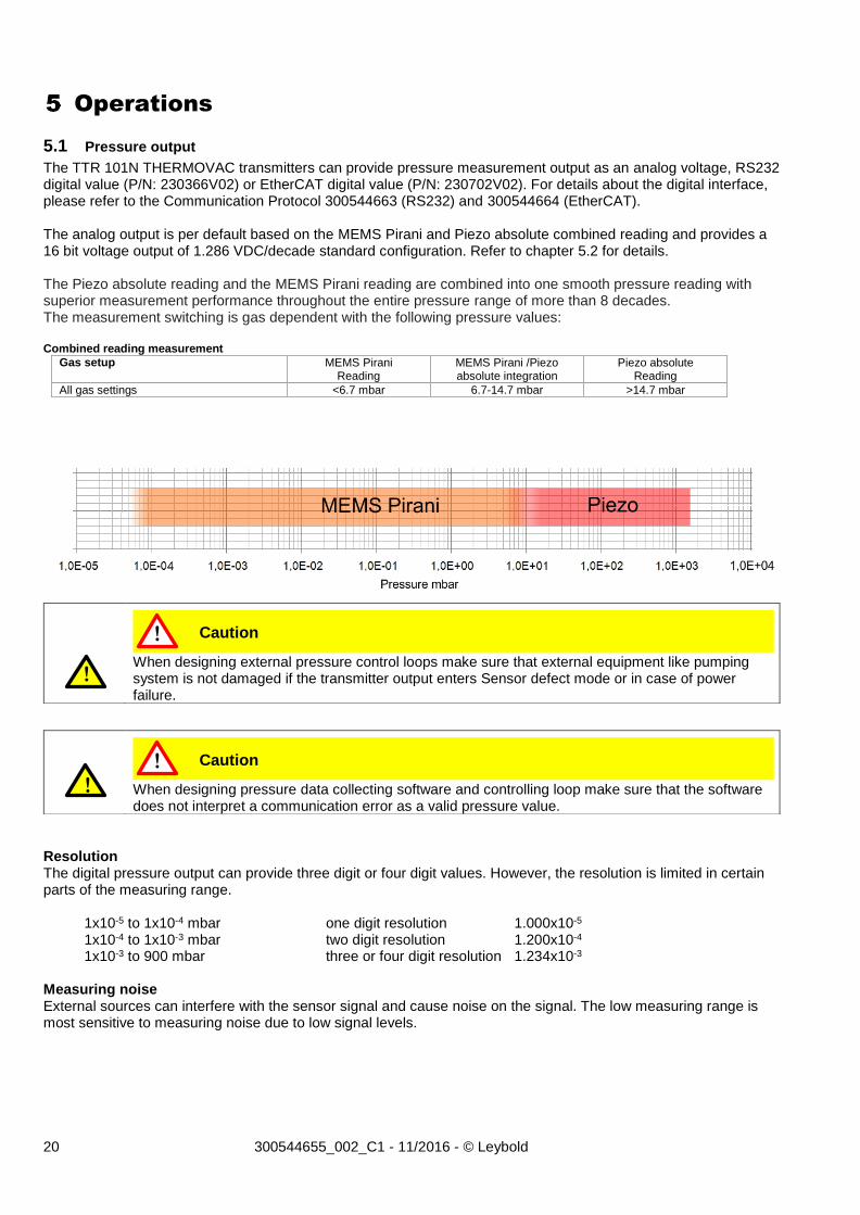
The TTR 101N THERMOVAC transmitters can provide pressure measurement output as an analog voltage, RS232 digital value (P/N: 230366V02) or EtherCAT digital value (P/N: 230702V02). For details about the digital interface, please refer to the Communication Protocol 300544663 (RS232) and 300544664 (EtherCAT). The analog output is per default based on the MEMS Pirani and Piezo absolute combined reading and provides a 16 bit voltage output of 1.286 VDC/decade standard configuration. Refer to chapter 5.2 for details. The Piezo absolute reading and the MEMS Pirani reading are combined into one smooth pressure reading with superior measurement performance throughout the entire pressure range of more than 8 decades. The measurement switching is gas dependent with the following pressure values: Combined reading measurement
Gas setup MEMS Pirani Reading
MEMS Pirani /Piezo absolute integration
Piezo absolute Reading
All gas settings <6.7 mbar 6.7-14.7 mbar >14.7 mbar
Resolution The digital pressure output can provide three digit or four digit values. However, the resolution is limited in certain parts of the measuring range. 1x10⁻⁵ to 1x10⁻⁴ mbar one digit resolution 1.000x10⁻⁵ 1x10⁻⁴ to 1x10⁻³ mbar two digit resolution 1.200x10⁻⁴ 1x10⁻³ to 900 mbar three or four digit resolution 1.234x10⁻³ Measuring noise External sources can interfere with the sensor signal and cause noise on the signal. The low measuring range is most sensitive to measuring noise due to low signal levels.
When designing external pressure control loops make sure that external equipment like pumping system is not damaged if the transmitter output enters Sensor defect mode or in case of power failure.
When designing pressure data collecting software and controlling loop make sure that the software does not interpret a communication error as a valid pressure value.
Caution
Caution
!
!
!
!
21 300544655_002_C1 - 11/2016 - © Leybold
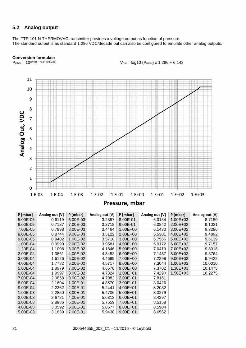
5.2 Analog output
The TTR 101 N THERMOVAC transmitter provides a voltage output as function of pressure. The standard output is as standard 1.286 VDC/decade but can also be configured to emulate other analog outputs. Conversion formulae: Pmbar = 10((Vout – 6.143)/1.286) Vout = log10 (Pmbar) x 1.286 + 6.143
P [mbar] Analog out [V] P [mbar] Analog out [V] P [mbar] Analog out [V] P [mbar] Analog out [V] 5.00E-05 0.6119 6.00E-03 3.2857 8.00E-01 6.0184 1.00E+02 8.7150 6.00E-05 0.7137 7.00E-03 3.3718 9.00E-01 6.0842 2.00E+02 9.1021 7.00E-05 0.7998 8.00E-03 3.4464 1.00E+00 6.1430 3.00E+02 9.3286 8.00E-05 0.8744 9.00E-03 3.5122 2.00E+00 6.5301 4.00E+02 9.4892 9.00E-05 0.9402 1.00E-02 3.5710 3.00E+00 6.7566 5.00E+02 9.6139 1.00E-04 0.9990 2.00E-02 3.9581 4.00E+00 6.9172 6.00E+02 9.7157 1.20E-04 1.1008 3.00E-02 4.1846 5.00E+00 7.0419 7.00E+02 9.8018 2.00E-04 1.3861 4.00E-02 4.3452 6.00E+00 7.1437 8.00E+02 9.8764 3.00E-04 1.6126 5.00E-02 4.4699 7.00E+00 7.2298 9.00E+02 9.9422 4.00E-04 1.7732 6.00E-02 4.5717 8.00E+00 7.3044 1.00E+03 10.0010 5.00E-04 1.8979 7.00E-02 4.6578 9.00E+00 7.3702 1.30E+03 10.1475
6.00E-04 1.9997 8.00E-02 4.7324 1.00E+01 7.4290 1.50E+03 10.2275
7.00E-04 2.0858 9.00E-02 4.7982 2.00E+01 7.8161
8.00E-04 2.1604 1.00E-01 4.8570 3.00E+01 8.0426
9.00E-04 2.2262 2.00E-01 5.2441 4.00E+01 8.2032
1.00E-03 2.2850 3.00E-01 5.4706 5.00E+01 8.3279 2.00E-03 2.6721 4.00E-01 5.6312 6.00E+01 8.4297 3.00E-03 2.8986 5.00E-01 5.7559 7.00E+01 8.5158 4.00E-03 3.0592 6.00E-01 5.8577 8.00E+01 8.5904 5.00E-03 3.1839 7.00E-01 5.9438 9.00E+01 8.6562
0
1
2
3
4
5
6
7
8
9
10
11
1 E-05 1 E-04 1 E-03 1 E-02 1 E-01 1 E+00 1 E+01 1 E+02 1 E+03
An
alo
g O
ut,
VD
C
Pressure, mbar

22 300544655_002_C1 - 11/2016 - © Leybold
Analog output setup The TTR 101 N THERMOVAC transmitter can emulate analog voltage outputs from other vacuum transmitters. (Only for transmitters with a serial interface.) The TTR 101 N THERMOVAC transmitter analog output can be assigned to the MEMS Pirani sensor measurement, Piezo absolute sensor measurement and the combined Piezo/MEMS Pirani reading. The analog output provides 16 bit resolution.
Due to curve form and limits, some of the alternative analog outputs will cause loss of measuring range and accuracy. For best performance use the standard Leybold analog output. Change of analog output setup does not interfere on digital reading.
Attention !
!
23 300544655_002_C1 - 11/2016 - © Leybold
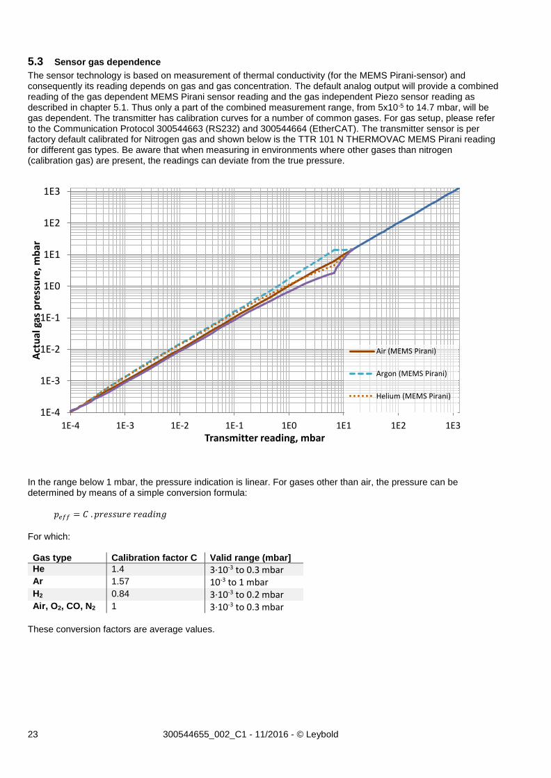
5.3 Sensor gas dependence
The sensor technology is based on measurement of thermal conductivity (for the MEMS Pirani-sensor) and consequently its reading depends on gas and gas concentration. The default analog output will provide a combined reading of the gas dependent MEMS Pirani sensor reading and the gas independent Piezo sensor reading as described in chapter 5.1. Thus only a part of the combined measurement range, from 5x10⁻⁵ to 14.7 mbar, will be gas dependent. The transmitter has calibration curves for a number of common gases. For gas setup, please refer to the Communication Protocol 300544663 (RS232) and 300544664 (EtherCAT). The transmitter sensor is per factory default calibrated for Nitrogen gas and shown below is the TTR 101 N THERMOVAC MEMS Pirani reading for different gas types. Be aware that when measuring in environments where other gases than nitrogen (calibration gas) are present, the readings can deviate from the true pressure.
In the range below 1 mbar, the pressure indication is linear. For gases other than air, the pressure can be determined by means of a simple conversion formula: 𝑝𝑒𝑓𝑓 = 𝐶 . 𝑝𝑟𝑒𝑠𝑠𝑢𝑟𝑒 𝑟𝑒𝑎𝑑𝑖𝑛𝑔
For which: Gas type Calibration factor C Valid range (mbar]
He 1.4 3∙10-3 to 0.3 mbar Ar 1.57 10-3 to 1 mbar H2 0.84 3∙10-3 to 0.2 mbar Air, O2, CO, N2 1 3∙10-3 to 0.3 mbar
These conversion factors are average values.
1E-4
1E-3
1E-2
1E-1
1E0
1E1
1E2
1E3
1E-4 1E-3 1E-2 1E-1 1E0 1E1 1E2 1E3
Act
ual
gas
pre
ssu
re, m
bar
Transmitter reading, mbar
Air (MEMS Pirani)
Argon (MEMS Pirani)
Helium (MEMS Pirani)
24 300544655_002_C1 - 11/2016 - © Leybold
Functions
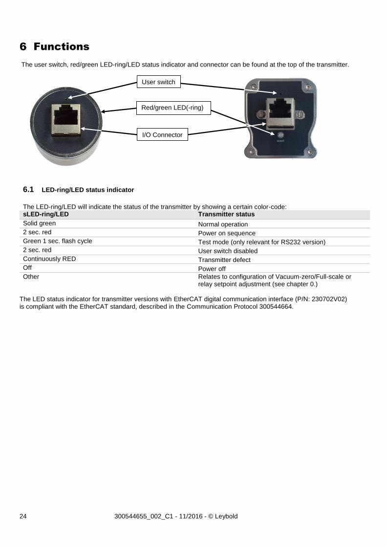
The user switch, red/green LED-ring/LED status indicator and connector can be found at the top of the transmitter.
6.1 LED-ring/LED status indicator
The LED-ring/LED will indicate the status of the transmitter by showing a certain color-code: sLED-ring/LED Transmitter status
Solid green Normal operation
2 sec. red Power on sequence
Green 1 sec. flash cycle Test mode (only relevant for RS232 version)
2 sec. red User switch disabled
Continuously RED Transmitter defect
Off Power off
Other Relates to configuration of Vacuum-zero/Full-scale or relay setpoint adjustment (see chapter 0.)
The LED status indicator for transmitter versions with EtherCAT digital communication interface (P/N: 230702V02) is compliant with the EtherCAT standard, described in the Communication Protocol 300544664.
User switch
Red/green LED(-ring)
I/O Connector
25 300544655_002_C1 - 11/2016 - © Leybold
6.2 Vacuum-zero adjustments and setpoint adjustments
For transmitter versions with RS232 digital communication interface (P/N: 230366V02) it is possible to make vacuum-zero (Zero) adjustments and setpoint adjustments using the RS232 digital communication interface. Refer to Communication Protocol 300544663 for further details. For transmitter versions with EtherCAT digital communication interface (P/N: 230702V02) it is possible to make vacuum-zero (Zero) adjustments and setpoint adjustments using the digital communication interface. Refer to Communication Protocol 300544664 for further details. Setpoint adjustments with the user switch can only be performed for transmitters with P/N: 230352V02, 230353V02, 230356V02. Zero adjustment before operation is recommended to obtain best measurement performance in the lowest part of the measuring range. Vacuum-zero adjustment is not required for measurements above 5x10⁻⁴ mbar. However, drift can occur over time and periodic vacuum-zero adjustments are then recommended to optimize measurement performance. MEMS Pirani-sensor vacuum-zero (Zero) adjustments
The vacuum-zero adjustment function changes the MEMS Pirani measurement offset at low pressure. Temporary or permanent shift in zero offset can be caused by contamination, corrosion, electrical noise interference and temperature.
The MEMS Pirani full scale adjustment allows the user to adjust the MEMS Pirani full scale reading (only possible by using the serial interface). Vent the transmitter to atmospheric pressure using the gas that corresponds to the gas calibration setup. Full scale adjustment can only be executed with air or Nitrogen.
By using User switch It is possible to perform vacuum-zero adjustments (Zero) of the MEMS Pirani-sensor by using the user switch. See chapter 6.3.
By using Serial interface For transmitter versions with a digital communication interface (P/N: 230366V02 (RS232) and P/N: 230702V02 (EtherCAT)) it is possible to make vacuum-zero and full-scale (Zero/FS) adjustments using the digital communication interface. Refer to Communication Protocol 300544663 (RS232) and 300544664 (EtherCAT) for further details.
To obtain best measuring performance, it is recommended that the transmitter is evacuated to a pressure below 1×10⁻⁵ mbar before executing zero adjustment of the MEMS Pirani sensor. Zero adjustment of the MEMS Pirani sensor can be executed at pressures higher than 1×10⁻⁵ mbar, but this can cause inaccurate readings in the lower part of the measuring range. If the pressure measured by the transmitter is higher than approximately 1x10⁻² mbar, then the zero adjustment cannot be executed. If the zero adjustment failed, the LED-ring/LED will flash red three times.
Zero adjustment only changes the low measuring range and will have no influence on measuring errors in the range from 1×10⁻² mbar and above. Full scale adjustment only changes the high measuring range and will have no influence on measuring errors in the range below 10 mbar.
Attention !
!
Attention !
!
26 300544655_002_C1 - 11/2016 - © Leybold
Piezo-sensor zero adjustments The Piezo zero is automatically zero adjusted when the MEMS Pirani sensor measurement is below 6.2×10⁻² mbar and consequently under normal operation it’s not necessary to perform user adjustments. The Piezo zero adjustment can only be executed when the MEMS Pirani pressure measurement is below 1.3×10⁻¹ mbar. The Piezo zero adjustment sets the Piezo zero reading. The Piezo atmospheric adjustment allows the user to adjust the atmospheric reading for the Piezo measurement (only possible by using the serial interface). The Piezo full scale adjustment allows the user to adjust the Piezo full scale reading. Vent the transmitter to atmospheric pressure using the gas that corresponds to the gas calibration setup. Full scale adjustment can only be executed with air or Nitrogen (only possible by using the serial interface).
By using Serial interface For transmitter versions with a digital communication interface (P/N: 230366V02 (RS232) and P/N: 230702V02 (EtherCAT)) it is possible to make zero adjustments and full scale adjustments using the digital communication interface. Refer to Communication Protocol 300544663 (RS232) and 300544664 (EtherCAT) for further details.
Before performing the atmospheric adjustment with the user switch, vent transmitter to Nitrogen or air pressure of 1000 mbar. The transmitter will only accept full-scale adjustment when the pressure readout is within 600 to 1000 mbar. Note that if the adjustment is performed at a true pressure different from 1000 mbar, it can cause measurement deviations in the upper part of the measuring range.
Caution !
!
27 300544655_002_C1 - 11/2016 - © Leybold
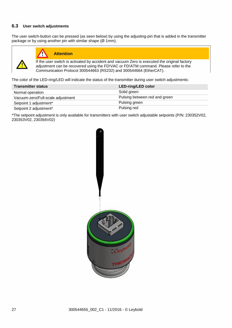
6.3 User switch adjustments
The user switch-button can be pressed (as seen below) by using the adjusting-pin that is added in the transmitter package or by using another pin with similar shape (Ø 1mm).
The color of the LED-ring/LED will indicate the status of the transmitter during user switch adjustments:
Transmitter status LED-ring/LED color
Normal operation Solid green
Vacuum-zero/Full-scale adjustment Pulsing between red and green
Setpoint 1 adjustment* Pulsing green
Setpoint 2 adjustment* Pulsing red
*The setpoint adjustment is only available for transmitters with user switch adjustable setpoints (P/N: 230352V02, 230353V02, 230356V02)
If the user switch is activated by accident and vacuum Zero is executed the original factory adjustment can be recovered using the FD!VAC or FD!ATM command. Please refer to the Communication Protocol 300544663 (RS232) and 300544664 (EtherCAT).
Attention !
!
28 300544655_002_C1 - 11/2016 - © Leybold
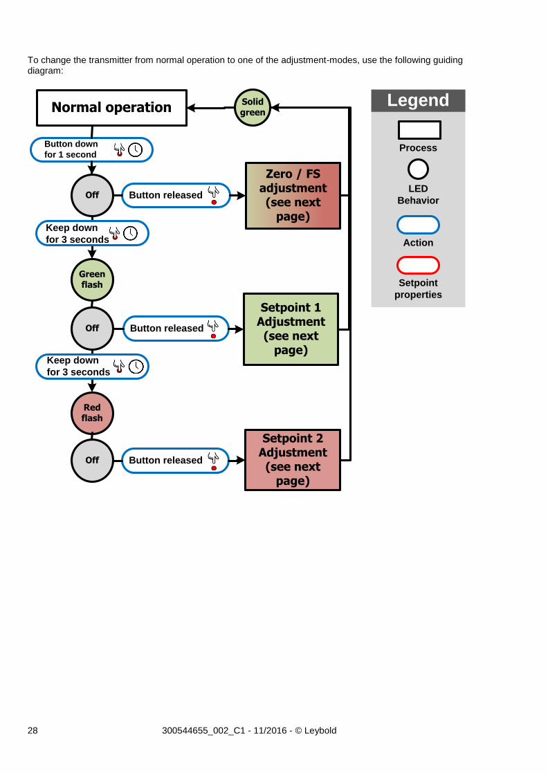
To change the transmitter from normal operation to one of the adjustment-modes, use the following guiding diagram:
Setpoint 1 Adjustment (see next
page)
Setpoint 2 Adjustment (see next
page)
Green flash
Red flash
Solidgreen
Zero / FS adjustment (see next
page)
Normal operation
Off
Off
Off
Button down
for 1 second
Button released
Keep down
for 3 seconds
Keep down
for 3 seconds
Button released
Button released
Process
Legend
LED
Behavior
Action
Setpoint
properties
29 300544655_002_C1 - 11/2016 - © Leybold
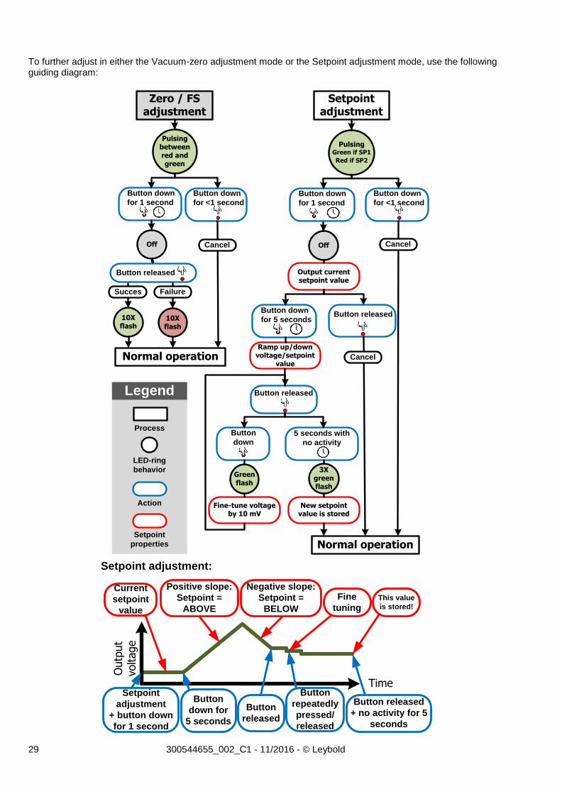
To further adjust in either the Vacuum-zero adjustment mode or the Setpoint adjustment mode, use the following guiding diagram:
Button down
for 1 second
Zero / FS adjustment
Setpointadjustment
Pulsing betweenred and green
Pulsing Green if SP1
Red if SP2
Off Off
10X flash
10X flash
Succes Failure
Button released
Button down
for <1 second
Normal operation
Button down
for <1 second
Button down
for 1 second
Normal operation
Output current setpoint value
Ramp up/down voltage/setpoint
value
Fine-tune voltage by 10 mV
New setpoint value is stored
Button releasedButton down
for 5 seconds
Button released
5 seconds with
no activity
Button
down
Green flash
3X green flash
Process
Legend
LED-ring
behavior
Action
Setpoint
properties
Cancel Cancel
Cancel
Current
setpoint
value
Positive slope:
Setpoint =
ABOVE
Negative slope:
Setpoint =
BELOW
Fine
tuningThis value
is stored!
Setpoint
adjustment
+ button down
for 1 second
Button
down for
5 seconds
Button
released
Button
repeatedly
pressed/
released
Button released
+ no activity for 5
seconds
Time
Outp
ut
voltage
Setpoint adjustment:
30 300544655_002_C1 - 11/2016 - © Leybold
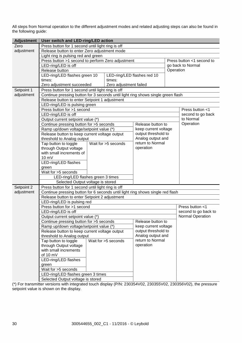
All steps from Normal operation to the different adjustment modes and related adjusting steps can also be found in the following guide: Adjustment User switch and LED-ring/LED action
Zero adjustment
Press button for 1 second until light ring is off
Release button to enter Zero adjustment mode
Light ring is pulsing red and green
Press button >1 second to perform Zero adjustment Press button <1 second to go back to Normal Operation
LED-ring/LED is off
Release button
LED-ring/LED flashes green 10 times: Zero adjustment succeeded
LED-ring/LED flashes red 10 times: Zero adjustment failed
Setpoint 1 adjustment
Press button for 1 second until light ring is off
Continue pressing button for 3 seconds until light ring shows single green flash
Release button to enter Setpoint 1 adjustment
LED-ring/LED is pulsing green
Press button for >1 second Press button <1 second to go back to Normal Operation
LED-ring/LED is off
Output current setpoint value (*)
Continue pressing button for >5 seconds Release button to keep current voltage output threshold to Analog output and return to Normal operation
Ramp up/down voltage/setpoint value (*)
Release button to keep current voltage output threshold to Analog output
Tap button to toggle through Output voltage with small increments of 10 mV
Wait for >5 seconds
LED-ring/LED flashes green
Wait for >5 seconds
LED-ring/LED flashes green 3 times
Selected Output voltage is stored
Setpoint 2 adjustment
Press button for 1 second until light ring is off
Continue pressing button for 6 seconds until light ring shows single red flash
Release button to enter Setpoint 2 adjustment
LED-ring/LED is pulsing red
Press button for >1 second Press button <1 second to go back to Normal Operation
LED-ring/LED is off
Output current setpoint value (*)
Continue pressing button for >5 seconds Release button to keep current voltage output threshold to Analog output and return to Normal operation
Ramp up/down voltage/setpoint value (*)
Release button to keep current voltage output threshold to Analog output
Tap button to toggle through Output voltage with small increments of 10 mV
Wait for >5 seconds
LED-ring/LED flashes green
Wait for >5 seconds
LED-ring/LED flashes green 3 times
Selected Output voltage is stored
(*) For transmitter versions with integrated touch display (P/N: 230354V02, 230355V02, 230356V02), the pressure setpoint value is shown on the display.
31 300544655_002_C1 - 11/2016 - © Leybold
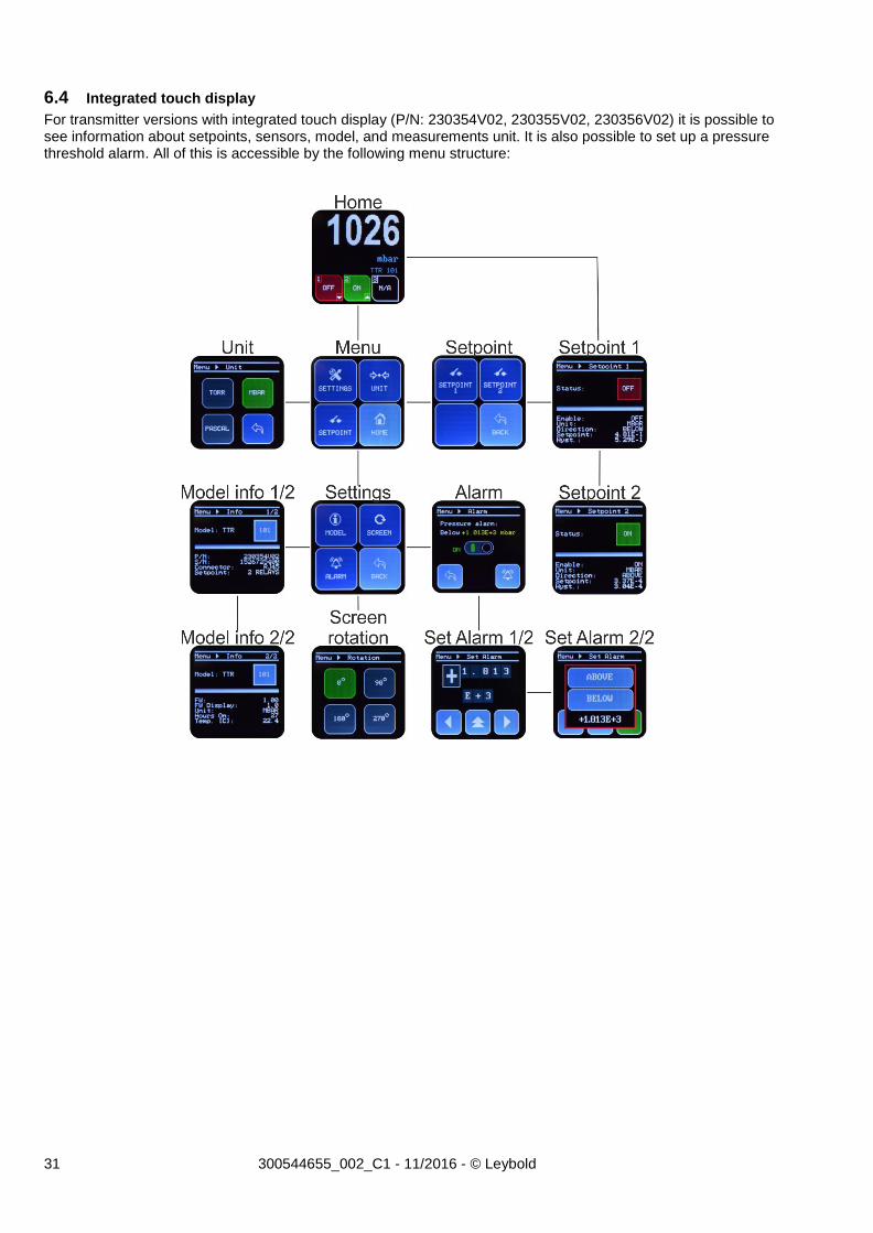
6.4 Integrated touch display
For transmitter versions with integrated touch display (P/N: 230354V02, 230355V02, 230356V02) it is possible to see information about setpoints, sensors, model, and measurements unit. It is also possible to set up a pressure threshold alarm. All of this is accessible by the following menu structure:
32 300544655_002_C1 - 11/2016 - © Leybold
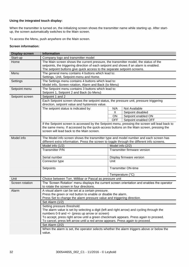
Using the integrated touch display: When the transmitter is turned on, the initializing screen shows the transmitter name while starting up. After start-up, the screen automatically switches to the Main screen. To access the Menu, push anywhere on the Main screen. Screen information: Display-screen Information
Start-up Company logo and transmitter model
Home The Main screen shows the current pressure, the transmitter model, the status of the setpoints, the triggering direction of each setpoint and shows if an alarm is enabled. The setpoint buttons give quick access to the separate setpoint-screens.
Menu The general menu contains 4 buttons which lead to: Settings, Unit, Setpoint-menu and Home.
Settings The Settings menu contains 4 buttons which lead to: Model info, Screen rotation, Alarm and Back (to Menu)
Setpoint menu The Setpoint menu contains 3 buttons which lead to: Setpoint 1, Setpoint 2 and Back (to Menu)
Setpoint screen Setpoint 1 and 2
Each Setpoint screen shows the setpoint status, the pressure unit, pressure triggering direction, setpoint value and hysteresis value.
The setpoint status is indicated by:
N/A Not Available
X Setpoint disabled
ON Setpoint enabled ON
OFF Setpoint enabled OFF
If the Setpoint screen is accessed by the Setpoint menu, pressing the screen will lead back to the same menu. If accessed by the quick-access buttons on the Main screen, pressing the screen will lead back to the Main screen.
Model info The Model info screen shows the transmitter type and model number and each screen has different extra information. Press the screen to toggle through the different info screens.
Model info (1/2) Model info (2/2)
Transmitter P/N
Transmitter firmware version
Serial number Display firmware version
Connector type Unit
Setpoints Transmitter ON-time
Temperature (°C)
Unit Choice between Torr, Millibar or Pascal as pressure unit
Screen rotation The ‘Screen Rotation’ menu displays the current screen orientation and enables the operator to rotate the screen in four directions.
Alarm A visual alarm can be set at a certain pressure. Press the green or red button to enable or disable the alarm. Press Set to change the alarm pressure value and triggering direction.
Set Alarm (1/2)
Setting pressure threshold: The alarm value is set by selecting a digit (left and right arrow) and cycling through the numbers 0-9 and +/- (press up arrow or screen) To accept, press right arrow until a green checkmark appears. Press again to proceed. To cancel, press left arrow until a red arrow appears. Press again to proceed.
Set Alarm (2/2)
When the alarm is set, the operator selects whether the alarm triggers above or below the value.

33 300544655_002_C1 - 11/2016 - © Leybold
FAQ (Frequently Asked Questions)
Applications Q: Can the transmitter and sensor element continuously withstand vibrations from a mechanical fore-pump? A: Yes – the MEMS Pirani sensor element can withstand continuous vibrations. Q: When the transmitter is pumped down and isolated by closing a valve the pressure is raising. Is the transmitter leaking? A: Not likely - when a confined space is evacuated and the pumping is stopped the pressure will rise because of outgassing, mainly by water vapor. The pressure can easily rise to a few mbar over time. Q: When the transmitter is leak checked on a helium leak detector. Leak reading is building up slowly after approximately 30 seconds. Is the transmitter leaking? A: No - the internal sealing of the TTR 101 N THERMOVAC transmitter uses elastomer FPM sealing and consequently helium molecules can permeate e through the FPM material and cause slow increase of helium leak readout. If a leaking transmitter is tested directly on a helium leak detector the leak is almost instantly displayed. Q: Can the transmitter be mounted in any orientation? A: Yes - the transmitter can be mounted in any orientation without compromise of performance or calibration. However it is recommended not to mount the transmitter with the flange port facing upwards to avoid contamination like particulates or liquids from entering the device. Q: Can the transmitter withstand instant ventilation? A: Yes - the MEMS Pirani and Piezo sensor elements are extremely robust to mechanical forces and can withstand continuous pressure cycles and instant air ventilation. Q: Can I connect a valve to be controlled by the transmitter relay contact? A: Driving inductive loads such as valves requires special precautions. Refer to detailed description in chapter 4.2. Q: How many pressure cycles can the transmitter withstand? A: Both the MEMS Pirani and Piezo sensor elements are very robust to pressure changes and the number of pressure cycles will have no effect on the lifetime of the transmitter. The sensor element is very robust to pressure changes and the number of pressure cycles will have no effect on the lifetime of the transmitter. The setpoint relay contact endurance is minimum 2,000,000 cycles at 30VDC/0.2A load. Analog output Q: What is the update rate of the analog output? A: 16 times per second. Q: What is the maximum length of analog output cable? A: The length of analog cable depends on cable quality and electrical noise environment. Cable lengths up to 100 m do not normally require any special precautions other than the cable must be screened. Q: The digital reading is correct but the analog output reading has some deviation from actual pressure? A: Check that the analog out is connected to a floating input and not an input that is connected to ground. If connected analog out return is connected to ground, the supply current will flow in the signal line and cause voltage drop and ground looping. Digital output Q: How fast can I request pressure measurements via the digital interface? A: 10 times per second is the fastest recommended pressure request frequency. Q: How long is the waiting time from turning power on to valid measuring values? A: The power on sequence is approximately 2 seconds. The light ring is illuminating red during power up sequence and the digital interface will not reply on commands. Reliable measurements are typically available within 1 minute. Q: The first character is sometimes lost in the transmitter digital communication reply? A: This can be caused by too fast transmitter communication reply. See RS delay command description in the Communication Protocol 300544663 (RS232).

34 300544655_002_C1 - 11/2016 - © Leybold
Calibration and adjustment Q: How often does the transmitter require calibration or Zero adjustment? A: It depends on the application and pressure range but in many applications user adjustment is never required. Factors that temporally or permanently can influence the measuring performance is contamination, corrosion, heat and electronic interference. Q: Will the transmitter retain user calibration after power is shut off? A: Yes - all transmitter parameters including calibration data are stored internally in the transmitter nonvolatile memory. Service and repair Q: Can the sensor element be changed if contaminated? A: No - the sensor elements cannot be changed without changing its measuring electronics. The transmitter flange assembly can be exchanged can be exchanged with the replacement part. See chapter 2.3. Q: A +24 VDC supply voltage has been connected to analog output+. Is the transmitter damaged? A: Likely - the analog output is not protected against applying power to the output pin. Q: Reverse voltage has been connected to power supply input. Is the transmitter damaged? A: Not likely – the transmitter power supply circuit has reverse voltage and over voltage protection, however, Leybold cannot guarantee that the transmitter will not be damaged. Q: The status light ring is constantly illuminating red? A: The red status indicates a defect MEMS Pirani sensor element most likely damaged by corrosion or contamination. It can also occur if electronics malfunction.

35 300544655_002_C1 - 11/2016 - © Leybold
Trouble shooting
Symptom Possible Cause/Remedy
No digital communication - Check electrical connections (3 wires from transmitter to communication equipment)
- Transmitter and communication equipment baud rates have to match
- Use of incorrect transmitter address. Try address 254 - Attention characters missing (@) - Termination characters missing (;FF)
NAK180 is received when transmitting setpoint commands
- The transmitter setup is locked. Refer to disable lock procedure in the communication protocol.
Incorrect pressure value - Other gas present than transmitter gas setting or trace of gas.
- Contaminated sensor. Transmitter repair required. - Corroded sensor. Transmitter repair required. - Perform a zero adjustment/FS adjustment. - Check Setting of Controller or display.
Incorrect pressure value at low pressure
- Contaminated sensor. Transmitter repair required. - Corroded sensor. Transmitter repair required. - Incorrect zero adjustment has been executed. - Transmitter exposed to heat or cooling air stream. - Perform a zero adjustment.
Incorrect pressure value at high pressure.
- Contaminated sensor. Transmitter repair required. - Corroded sensor. Transmitter repair required. - Incorrect FS adjustment has been executed. - Other gas or gas trace present than transmitter gas setting. - Perform a FS adjustment.
Set point relay does not trip - Setpoint not enabled. - Setpoint value not set to proper value. - Setpoint direction is different than the user expects. - Check electrical connection. - Check part number to see if transmitter has setpoint relays.
No analog output - Power supply turned off. - Check electrical connections.
Status light ring illuminating red - Sensor element defect.
36 300544655_002_C1 - 11/2016 - © Leybold
Maintenance
Transmitter failures due to contamination are not covered by the warranty.
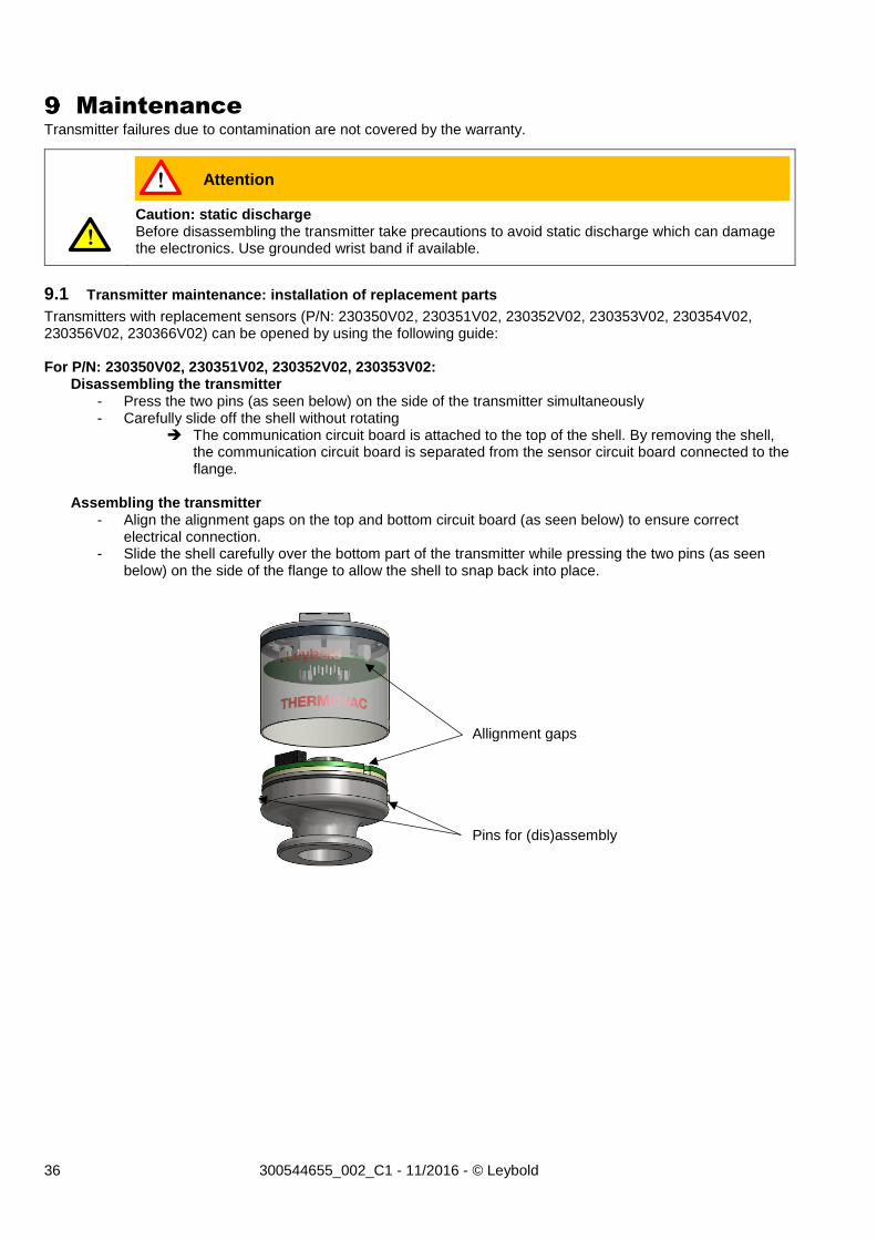
9.1 Transmitter maintenance: installation of replacement parts
Transmitters with replacement sensors (P/N: 230350V02, 230351V02, 230352V02, 230353V02, 230354V02, 230356V02, 230366V02) can be opened by using the following guide: For P/N: 230350V02, 230351V02, 230352V02, 230353V02:
Disassembling the transmitter - Press the two pins (as seen below) on the side of the transmitter simultaneously - Carefully slide off the shell without rotating
The communication circuit board is attached to the top of the shell. By removing the shell, the communication circuit board is separated from the sensor circuit board connected to the flange.
Assembling the transmitter
- Align the alignment gaps on the top and bottom circuit board (as seen below) to ensure correct electrical connection.
- Slide the shell carefully over the bottom part of the transmitter while pressing the two pins (as seen below) on the side of the flange to allow the shell to snap back into place.
Caution: static discharge Before disassembling the transmitter take precautions to avoid static discharge which can damage the electronics. Use grounded wrist band if available.
Attention !
!
Allignment gaps
Pins for (dis)assembly
37 300544655_002_C1 - 11/2016 - © Leybold
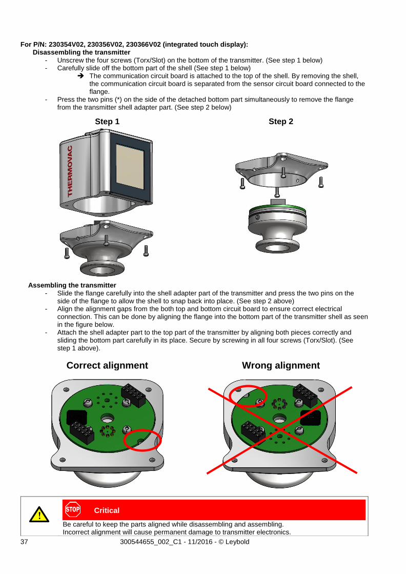
For P/N: 230354V02, 230356V02, 230366V02 (integrated touch display): Disassembling the transmitter
- Unscrew the four screws (Torx/Slot) on the bottom of the transmitter. (See step 1 below) - Carefully slide off the bottom part of the shell (See step 1 below)
The communication circuit board is attached to the top of the shell. By removing the shell, the communication circuit board is separated from the sensor circuit board connected to the flange.
- Press the two pins (*) on the side of the detached bottom part simultaneously to remove the flange from the transmitter shell adapter part. (See step 2 below)
Step 1 Step 2
Assembling the transmitter - Slide the flange carefully into the shell adapter part of the transmitter and press the two pins on the
side of the flange to allow the shell to snap back into place. (See step 2 above) - Align the alignment gaps from the both top and bottom circuit board to ensure correct electrical
connection. This can be done by aligning the flange into the bottom part of the transmitter shell as seen in the figure below.
- Attach the shell adapter part to the top part of the transmitter by aligning both pieces correctly and sliding the bottom part carefully in its place. Secure by screwing in all four screws (Torx/Slot). (See step 1 above).
Correct alignment Wrong alignment
Be careful to keep the parts aligned while disassembling and assembling. Incorrect alignment will cause permanent damage to transmitter electronics.
Critical !
38 300544655_002_C1 - 11/2016 - © Leybold
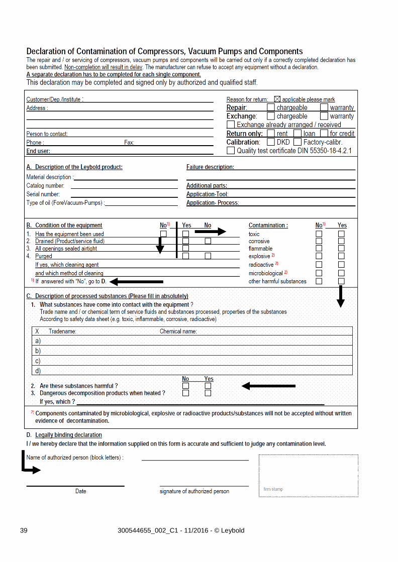
Declaration of Contamination
Safety information on contamination of compressors, vacuum pumps and components. Scope: Every employer (user) is held responsible for the health and safety of his employees. This also applies to service personnel performing maintenance work either at the premises of the user or the service company in charge. By means of the declaration attached the contractor is to be informed about any possible contamination of the compressor, vacuum pump or component sent in for servicing. Based on this information the contractor will be able to take the necessary safety precautions. Preparation before dispatch Before shipping any parts, the user must complete the following declaration and add it to the dispatch papers. All dispatch instructions laid down in the manual must be followed e.g.: • Drain all service fluids • Remove filter elements • Seal all openings airtight • Pack / handle appropriately • Attach the declaration of contamination outside of the packaging
39 300544655_002_C1 - 11/2016 - © Leybold
40 300544655_002 - 10/2015 - © Leybold
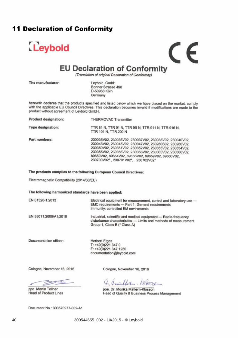
Declaration of Conformity

41 300544655_002 - 10/2015 - © Leybold
Notes
42 300544655_002 - 10/2015 - © Leybold
Sales and Service