Extending the concept of analog Butterworth filter for fractional order systems
12
Extending the concept of analog Butterworth filter for fractional order systems Anish Acharya a , Saptarshi Das b,n , Indranil Pan c , Shantanu Das d a Department of Instrumentation and Electronics Engineering, Jadavpur University, Salt Lake Campus, LB-8, Sector 3, Kolkata-700098, West Bengal, India b Communications, Signal Processing and Control Group, School of Electronics and Computer Science, University of Southampton, Southampton SO17 1BJ, United Kingdom c MERG, Energy, Environment, Modelling and Minerals (E 2 M 2 ) Research Section, Department of Earth Science and Engineering, Imperial College London, Exhibition Road, London SW7 2AZ, United Kingdom d Reactor Control Division, Bhabha Atomic Research Centre, Mumbai-400085, Maharashtra, India article info Article history: Received 18 October 2012 Received in revised form 14 April 2013 Accepted 9 July 2013 Available online 19 July 2013 Keywords: Butterworth filter Fractional order filter Fractional order linear system w-plane stability Analog filter design abstract This paper proposes the design of fractional order (FO) Butterworth filter in complex w- plane (w¼s q ; q being any real number) considering the presence of under-damped, hyper- damped, ultra-damped poles. This is the first attempt to design such fractional Butter- worth filters in complex w-plane instead of complex s-plane, as conventionally done for integer order filters. First, the concept of fractional derivatives and w-plane stability of linear fractional order systems are discussed. Detailed mathematical formulation for the design of fractional Butterworth-like filter (FBWF) in w-plane is then presented. Simula- tion examples are given along with a practical example to design the FO Butterworth filter with given specifications in frequency domain to show the practicability of the proposed formulation. & 2013 Elsevier B.V. All rights reserved. 1. Introduction In recent years, fractional calculus is being widely used in modeling the dynamics of many real life phenomena due to the fact that it has higher capability of providing accurate description than the integer dynamical systems. This added flexibility of FO systems is mainly due to the fact that poles in higher Riemann sheets which often contribute to the important dynamical features of physical systems can easily be analyzed and modeled using this technique e.g. the consideration of hyper-damped and ultra-damped poles etc. Thus due to greater flexibility in modeling, more accurate analysis and control design, fractional derivatives have been useful in many fields like visco-elasticity, acoustics, rheology, polymeric chemistry, biophysics etc. [1]. The application of fractional order systems as design elements have mostly been used in control and signal processing community as FO controllers and FO filters [2,3]. Though different fractional order controllers like CRONE, PI λ D μ , FO lead-lag compensators have already been famous, there are very few attempts on systematic design of FO filters. Previous attempts on FO analog filter design have mostly been restricted in the generalization of the first order and second order analog infinite impulse response (IIR) transfer function templates as fractional order transfer functions by Radwan et al. [4,5]. But the authors in [4,5] did not consider the pole locations and the nature of the poles in higher Riemann sheets which is inevitable while dealing with fractional order linear dynamical systems. Other relevant approaches Contents lists available at ScienceDirect journal homepage: www.elsevier.com/locate/sigpro Signal Processing 0165-1684/$ -see front matter & 2013 Elsevier B.V. All rights reserved. http://dx.doi.org/10.1016/j.sigpro.2013.07.012 n Corresponding author. Tel.: +44 7448572598. E-mail addresses: [email protected] (A. Acharya), [email protected], [email protected] (S. Das), [email protected], [email protected] (I. Pan), [email protected] (S. Das). Signal Processing 94 (2014) 409–420
Transcript of Extending the concept of analog Butterworth filter for fractional order systems
Contents lists available at ScienceDirect
Signal Processing
Signal Processing 94 (2014) 409–420
0165-16http://d
n CorrE-m
saptarshindranilshantan
journal homepage: www.elsevier.com/locate/sigpro
Extending the concept of analog Butterworth filterfor fractional order systems
Anish Acharya a, Saptarshi Das b,n, Indranil Pan c, Shantanu Das d
a Department of Instrumentation and Electronics Engineering, Jadavpur University, Salt Lake Campus, LB-8, Sector 3, Kolkata-700098,West Bengal, Indiab Communications, Signal Processing and Control Group, School of Electronics and Computer Science, University of Southampton,Southampton SO17 1BJ, United Kingdomc MERG, Energy, Environment, Modelling and Minerals (E2M2) Research Section, Department of Earth Science and Engineering, ImperialCollege London, Exhibition Road, London SW7 2AZ, United Kingdomd Reactor Control Division, Bhabha Atomic Research Centre, Mumbai-400085, Maharashtra, India
a r t i c l e i n f o
Article history:Received 18 October 2012Received in revised form14 April 2013Accepted 9 July 2013Available online 19 July 2013
Keywords:Butterworth filterFractional order filterFractional order linear systemw-plane stabilityAnalog filter design
84/$ - see front matter & 2013 Elsevier B.V.x.doi.org/10.1016/j.sigpro.2013.07.012
esponding author. Tel.: +44 7448572598.ail addresses: [email protected] ([email protected], [email protected] (S. Das),[email protected], [email protected]@magnum.barc.gov.in (S. Das).
a b s t r a c t
This paper proposes the design of fractional order (FO) Butterworth filter in complex w-plane (w¼sq; q being any real number) considering the presence of under-damped, hyper-damped, ultra-damped poles. This is the first attempt to design such fractional Butter-worth filters in complex w-plane instead of complex s-plane, as conventionally done forinteger order filters. First, the concept of fractional derivatives and w-plane stability oflinear fractional order systems are discussed. Detailed mathematical formulation for thedesign of fractional Butterworth-like filter (FBWF) in w-plane is then presented. Simula-tion examples are given along with a practical example to design the FO Butterworth filterwith given specifications in frequency domain to show the practicability of the proposedformulation.
& 2013 Elsevier B.V. All rights reserved.
1. Introduction
In recent years, fractional calculus is being widely usedin modeling the dynamics of many real life phenomenadue to the fact that it has higher capability of providingaccurate description than the integer dynamical systems.This added flexibility of FO systems is mainly due to thefact that poles in higher Riemann sheets which oftencontribute to the important dynamical features of physicalsystems can easily be analyzed and modeled using thistechnique e.g. the consideration of hyper-damped andultra-damped poles etc. Thus due to greater flexibility in
All rights reserved.
. Acharya),
(I. Pan),
modeling, more accurate analysis and control design,fractional derivatives have been useful in many fields likevisco-elasticity, acoustics, rheology, polymeric chemistry,biophysics etc. [1]. The application of fractional ordersystems as design elements have mostly been used incontrol and signal processing community as FO controllersand FO filters [2,3]. Though different fractional ordercontrollers like CRONE, PIλDμ, FO lead-lag compensatorshave already been famous, there are very few attempts onsystematic design of FO filters. Previous attempts on FOanalog filter design have mostly been restricted in thegeneralization of the first order and second order analoginfinite impulse response (IIR) transfer function templatesas fractional order transfer functions by Radwan et al.[4,5]. But the authors in [4,5] did not consider the polelocations and the nature of the poles in higher Riemannsheets which is inevitable while dealing with fractionalorder linear dynamical systems. Other relevant approaches
A. Acharya et al. / Signal Processing 94 (2014) 409–420410
of designing fractional second order filters can be found inYan Li et al. [6]. Initial effort in this direction can be seen inSoltan et al. [7] with fractional capacitor and inductorbased Butterworth filter design. Our present paper is thefirst attempt to extend the concept of assigning poles of afractional order Butterworth filter lying on a circle incomplex w-plane with consideration of its stability usingwell known Matignon′s theorem [8]. A detailed analysisregarding the stability of different fractional order systemscan be found in Radwan et al. [9]. The poles of such a filterwill comprise of several cases like co-existence of under-damped, hyper-damped and ultra-damped poles whichhas not been investigated yet. Several other approaches infractional filter design may include step filter [10,11],different sinusoidal oscillators [12,13], multi-vibrator cir-cuits [14] etc.
The Butterworth filter is one of the most popular analogfilter design paradigms, first described in 1930 by StephenButterworth [15]. The basic philosophy of the conventionalor integer order analog Butterworth filter is well practiced invarious applications. It is designed to have a frequencyresponse as flat as it is possible. The frequency response ofthese filters is monotonic and the sharpness of the roll-offfrom pass band to stop band is determined by the order ofthe filter. For conventional Butterworth filters the polesassociated with the magnitude squared function are equallydistributed in angle on a circle in the complex s-planearound the origin and having radius equal to the cut-offfrequency (Ωc). When the cut-off frequency and the filterorder are specified, the poles can be obtained readily andfrom the pole position the transfer function of the filter caneasily be obtained. Now, while designing a Butterworth filterwe generally have four specifications, the pass band fre-quency (Ωp), stop band frequency (Ωs), maximum allowablepass band and stop band attenuation (αp; αs). The motivationof designing a fractional order Butterworth filter instead ofthe conventional integer order Butterworth filter is high-lighted in this paper in the light of optimally finding the filterorder to meet these design specifications rather than design-ing an over-specified filter.
As discussed earlier, given these specifications when aButterworth filter is to be designed, the optimum orderwhich is capable of meeting these specifications may be afraction which is conventionally raised to the nearestinteger value due to unavailability of filter order being afraction. This is just similar to adding a bit more factor ofsafety in the design or over-satisfying the design specifica-tions as the standard practice was to opt for a filter withnext integer value. Hence it is obviously desirable neitherto under satisfy nor to over satisfy the design specifica-tions which can easily be met with the concept offractional order filters with tunable parameters. Withfurther enhancement of the realization techniques forfractional order filters, it will be possible to satisfy theexact requirements according to the given specifications.The other reason behind opting for fractional order Butter-worth filter over the integer order one is the flexibility ofdesign with the poles in w-plane, as it is well known thatthe s-plane design is a sub-set of the fractional orderdesign considering the possibility of existing filter poles indifferent Riemann sheets.
Although there are several works on Butterworth filterdesign in past but its modification with the concept offractional order derivatives is new. By doing so, theconventional s-plane stability needs to be modified firstfor fractional systems and we here systematically pro-posed the way of designing such filters by considering thew-plane stability given by Matignon′s theorem [8] forfractional order systems. In a recent paper Soltan et al.[7], the design of the fractional order Butterworth filter hasbeen reported. However the approach adopted in [7] hasbeen quite different from the one proposed in our presentpaper. In [7] the fractional Butterworth filter design hasbeen attempted from a circuit theory point of view, wheretwo passive elements have been taken as Z1 ¼ sβLandZ2 ¼ 1=sαC and thus designed the Butterworth filter fol-lowing the conventional circuit design principles. How-ever, the number of stable poles differs from the expectedone. For example, in the pole location data provided in [7],a 0.7 order filter having two poles on the circle has beendemonstrated. However, it is understandable from [16],[17] that the filter order being 0.7 we would expect 7 polesdistributed over 10 Riemann sheets. Thus the formulationof FO Butterworth filter has been presented in a differentway in order to generalize the design technique with stateof the art analysis methodologies concerning the stabilityof fractional order linear systems. It is to be noted that in[7], the number of poles has been considered to be fourwhich is a special case of fractional second order Butter-worth filter whereas many other variants may also existand has been generalized and illustrated with designexamples in the present paper.
In this paper the fractional Butterworth filter has beenformulated in the w-plane (w¼ sq; q∈ℝþ). Thus all possibletypes of poles (under-damped, hyper-damped, ultra-damped) have been taken into account. An analyticalformulation of the filter is done in the w-plane and certainconditions for the location of the stable and the unstablepoles are derived. The essence of classical Butterworthfilter is kept unchanged and it is found that even in case ofthe fractional order formulation, the poles are placed alongthe circumference of a circle whose radius is equal to thecut-off frequency. Thus, by the proposed formulation allthe stable poles have been taken into account. The corre-sponding transfer functions are obtained in w-plane andare then mapped back into the s-plane using the relations¼w1=q. The corresponding response curves are obtainedto confirm the maximally flat Butterworth nature.
Since this is one of the first approaches towards filterdesign in the w-plane, some generic issues related tofractional order filter design need to be discussed. It isknown from the elementary knowledge of fractional orderlinear systems that a filter having an order P=Q impliesthat P number of poles are distributed over Q Riemannsheets. However, this result is a serious issue related to theorder of the filter. Say the order of 0.9 has been wronglyestimated as 0.99 or 0.999 or that a first order system hasbeen wrongly estimated as 1.001. So, it is worth consider-ing whether increase in the number of poles and numberof Riemann sheets for capturing delicate frequencydomain information is actually required, since this wouldlead to higher design complexity [16,17]. For a 0.9 order
A. Acharya et al. / Signal Processing 94 (2014) 409–420 411
filter, the proposition will require 9 poles distributed over10 Riemann sheets, however if the order is estimated to be0.99, 99 poles distributed over 100 Riemann sheets are tobe handled, which will be cumbersome to realize inhardware. This resulting complexity would make it diffi-cult to generalize filters in fractional domain and theadvantage of greater flexibility will be outweighed byfabrication costs. So, a design scheme which consideredthe relative trade-off between complexity and accuracyhas been adopted. Thus for a filter whose overall order is afraction, it is better to realize it only up to the first decimalplace (by truncating the trailing decimals) and thenincreasing the accuracy by intuitive judgment for improv-ing the frequency domain characteristics.
There are many different connotations related to theterm “filtering”. In the classical sense, filter design refers toFIR or IIR structures which are designed to satisfy somefrequency domain specifications like cut-off frequenciesfor the pass-band or stop band, maximum allowableripples in magnitude response etc. This notion of “filter-ing” is considered in the present paper. The other notion offiltering may be from the point of view of the theory oflinear estimation [18]. In such cases the filter designresults in some FIR/IIR structure which minimizes someperformance objective in time domain, e.g. Wiener filter.The third paradigm of filtering is a model based stateestimation or parameter estimation technique like theKalman filter, extended and unscented Kalman filter etc.This concept has been augmented to obtain differentenhanced performance objectives and for varied complexsystems with H1 filtering and particle filtering [19]. In[20], discusses the latest development in this categoryusing fuzzy logic. This has been an active research topic forthe last few decades. But in recent years, with the adventof fractional calculus in system design, our notions offiltering for all the three above mentioned paradigms needto be modified in this light. Our present work can be seenas a first step for systematic fractional filter design withthe consideration of stability for fractional order systems.Time domain filters like fuzzy [20] or H1 filtering [21]require some sort of a system model. However, in case ofconventional IIR/FIR filtering, the technique is applied onthe frequency spectrum of the signal directly. Hence theneed of a system model is eliminated.
In cases where the signal is corrupted by randomdisturbances or noise, linear estimation based filtering tech-nique works well [18]. But in many industrial processes thereis a clearly identified frequency band of interest (or passband), and rest of the frequency spectrum is not important.In such cases, simple FIR/IIR filtering techniques are pre-ferred over model based filters to reduce design complexity.All these stochastic filtering techniques require additionalparameters for their design unlike classical FIR/IIR filterdesign. For example, mixing properties (additive/multiplica-tive nature), statistical properties of the noise before mixing,parameterized linear/nonlinear model of the system gener-ating the signal, upper bound of the disturbance spectra etc.are required depending on the specific design techniques.
We propose here a new paradigm of designing frac-tional Butterworth filter to meet exact design require-ments which is not possible in conventional integer order
filter design. We have also shown that integer orderButterworth filter will always under-satisfy or over-satisfy the design specifications. The proposed techniqueis a new way of looking at analog filter design withfractional calculus based techniques. The magnitude roll-off can be adjusted to any desired slope, which can only beachieved using fractional order systems. While dealingwith fractional order transfer functions, the w-plane sta-bility concepts or Matignon′s theorem should be usedinstead of the conventional s-plane stability. It is to benoted that in recent years several efforts have been thereto propose new automatic controller design using theconcept of w-plane stability for example [22–24]. This isthe first attempt to extend the concept of stability inautomatic control design to analog Butterworth filterdesign using w-plane stability notion for FO systems.Existing state of the art design methods would increasethe order of the IIR filter to meet design specificationsor to get a smaller transition band. Since fractionalorder systems are inherently infinite dimensional,they naturally model the exact magnitude roll-off. Theorder of realization can be chosen by the user after theexact order of the filter is calculated from the frequencydomain specifications.
The rest of the paper is organized as follows. Section 2reviews the fundamentals of fractional calculus required tounderstand the mathematical formulation of the fractionalorder Butterworth filter. In Section 3 the mathematicalformulation for the realization of fractional Butterworthfilter is introduced. In Section 4 simulation results arepresented. Section 5 illustrates a realistic example of design-ing a fractional order Butterworth filter from given specifica-tions. The paper ends in Section 6 with the conclusions andsome comments about the future scope in this field.
2. Basics of fractional calculus based linear dynamicalsystems
The basics of fractional calculus that has been used inthis paper, are discussed here as the background of thefilter design technique.
2.1. Functions used in fractional calculus
Some important functions in relation to fractionalcalculus are as follows:
i.
Gamma functionΓðzÞ ¼Z 1
0e�uuz�1du; ∀z∈ℝ ð1Þ
For complex z the real part has to be finite to get a finitevalue of the gamma function.
ii.
Beta functionBðp; qÞ ¼Z 1
0ð1�uÞp�1uq�1du;p; q∈ℝþ ð2Þ
The relation between the gamma function and the betafunction is Bðp; qÞ ¼ ðΓðpÞΓðqÞ=Γðpþ qÞÞ.

A. Acharya et al. / Signal Processing 94 (2014) 409–420412
2.2. Definitions of fractional differ-integrals
The two popular definitions of fractional differ-integrationare as follows [1]
i.
TableType
Pol
jargqπ=qπojarg
Grunwald–Letnikov (G–L) definitionThis is basically an extension of the backward finitedifference formula for successive differentiation. Thisformula is used widely for the numerical solution offractional differentiation or integration of a function.According to Grunwald–Letnikov definition the αthorder differ-integration of a function f ðtÞ is defined as
Dαt f ðtÞ ¼ lim
h-0
1hα
∑1
j ¼ 0ð�1Þj Γðαþ 1Þ
Γðjþ 1ÞΓðα�jþ 1Þ f ðt�jhÞ
ð3Þ
ii.
Riemann–Liouville (R–L) definitionThis is an extension of n-fold successive integra-tion. The αth order integration of a function f ðtÞ isdefined asaIαt f ðtÞ ¼
1Γð�αÞ
Z t
a
f ðτÞðt�τÞαþ1 dτ fora; α∈ℝ; αo0 ð4Þ
and similarly the αthorder differentiation of a func-tion f ðtÞ is defined as
aDαt f ðtÞ ¼
1Γðn�αÞ
dn
dtn
Z t
a
f ðτÞðt�τÞα�nþ1 dτforn�1oαon ð5Þ
2.3. Stability regions in w-plane
Generally, for the multi-valued function defined asw¼ s
1Q ¼ sq where Q∈N there are Q sheets in the Riemann
surface. The sector �π=QoargðwkÞoπ=Q corresponds tothe first Riemann sheet and k is the number of poles. Thuswhen poles of any fractional order system in s-plane aremapped into w-plane, all the Riemann sheets are takeninto account. Hence all the different kinds of poles show-ing different dynamical behaviors are considered, espe-cially the ultra-damped and hyper-damped poles [25]. Thestable region is now constrained within the region [8]
argjðwkÞj4qπ
2ð6Þ
Table 1 shows the different pole types and their corre-sponding regions in the w-plane.
3. Proposal for a new fractional order Butterworth(FBW)-like filter
In this section, a fractional Butterworth like filter hasbeen proposed using the concept of w-plane stability.The poles are located on the w-plane which consists of
1of poles depending on their position in the w-plane.
e position Comment on pole nature
ðwÞjoqπ=2 Unstable2o jargðwÞjoqπ Stable under-dampedjargðwÞjoπ Stable hyper-damped
ðwÞj ¼ π Stable ultra-damped
all the poles lying on different higher Riemann sheets.Then the stability criterion is taken under considerationand all the unstable poles are rejected and a fractionalorder BW like filter can be obtained. The concept issomewhat similar to the conventional notion of findinginteger BW filter poles lying on a circle and then discard-ing the right-half plane poles in order to avoid instability.The FBW filter is developed on the lines of the integerorder Butterworth filter with the considerations of thestability of fractional linear systems [26].
Theorem 3.1. The pole locations of a FO Butterworth low-pass filter of any real order P=Q ; P;Qf g∈Zþ are given bywk ¼ 7 jΩCejð2k�1Þπ=2P , where k¼ 1;2;⋯; P and the condi-tion for stability of the roots is given by argjðwkÞj4 qπ
2 ,where q¼ 1=Q is the commensurate order and P is thenumber of poles distributed over Q Riemann sheets.
ProofThe squared magnitude function of an analog Butter-
worth filter is given by the form
jHðjΩÞj2 ¼ 11þ ðΩ=ΩcÞ2N
ð7Þ
where Nis the order of the filter.Now considering s¼ jΩ ⇒Ω¼ s=j, the squared magni-
tude system function is of the form
HðsÞHð�sÞ ¼ 11þ ðs=jΩcÞ2N
ð8Þ
For fractional order filters the magnitude squaredfunction would be written in terms of fractional powersof Laplace variable sq ¼w. Then we have the magnitudesquared function in w-plane as
HðwÞHð�wÞ ¼ 11þ ð�w2=ΩC
2ÞPð9Þ
So if P=Q ; P;Qf g∈Zþ be the order of the filter whereq¼ 1=Q ; q∈ℝþ, where q is the commensurate order hencewe now have P number of poles distributed over QRiemann sheets. Therefore the design of P=Q order FBWlike filter is similar to design a Pth order integer Butter-worth filter with the poles equally distributed on thecircumference of a circle in the complex w-plane whileonly discarding the unstable poles using the relation (6).So in w-plane we find the pole locations from thecharacteristic polynomial
1þ �w2
ΩC2
� �P
¼ 0 ð10Þ
This is being proposed as the Butterworth like poly-nomial which has been expressed as a function of winstead of s. Hence the pole locations are found to bewk ¼ 7 jΩCejð2k�1Þ π2P , where k¼ 1;2;…; P. and the criterionfor stable poles is the same as (6).
The results are illustrated and the natures of the polesare investigated for various cases. Let P ¼ 1 then the polesare located at wk ¼ 7 jΩCejðπ=2Þ ¼ 7ΩC . The poles locatedwithin the region 7qðπ=2Þ are unstable, hence it isobvious that w¼ þΩC corresponds to unstable system.Therefore, we consider only w¼�ΩC and thus the transferfunction of ð1=Q Þthorder filter and its mapping back to the

A. Acharya et al. / Signal Processing 94 (2014) 409–420 413
s-plane is found to be
HðwÞ ¼ ΩC
wþΩC⇒HðsÞ ¼ ΩC
sq þΩCð11Þ
Therefore, here we got a single ultra-damped pole forthe FBW filter.
Now when P ¼ 2 is considered, the pole locations arefound to be w¼ 7 jΩCejðπ=4Þ, 7 jΩCeð3π;4Þwhich may bestable depending on the commensurate order q. Therefore,the transfer function becomes
HðsÞ ¼ Ω4C
ðs2q�ffiffiffi2
pΩCsq þΩC
2Þðs2q þffiffiffi2
pΩCsq þΩC
2Þð12Þ
It is interesting to note that for classical second orderButterworth filter, seems to have the same structure as in(12), except that the unstable poles are in the right half w-plane (yielding negative coefficient of transfer function).For similar classical design i.e.,q¼ 1, the term ðs2q�
ffiffiffi2
pΩCsq
þΩC2Þ used to be discarded as they represent unstable
complex conjugates in s-plane. But for fractional ordersystems, these poles may be stable and thus must beincluded in the design depending on the respective stabi-lity criteria. Therefore fractional order transfer functionswith negative coefficients with poles lying in the right halfpart of w-plane, but outside the instability region, is aneffective way for the development of filters having anyarbitrary real order.
Now the nature of the poles is dependent on thecommensurate order as discussed in Section 2.3. Onanalyzing the nature of the roots for different combina-tions of Pandq, i.e. for different orders of the filters, thenature of the poles need to be judged for possible effects inthe filtering action using the notions given in Table 1. Forsimplicity, the pole locations of the fractional filter aredesigned for overall order less than unity. In other words,for a fractional Butterworth like filter with order greaterthan unity, the integer and the fractional parts are to bedesigned separately and then needs to be cascadedtogether. This is important due to the fact that for ordergreater than unity (e.g. order N þ ðP=Q Þ; N∈Zþ; Q4P;P;Qf g∈ℝþ), the number of poles in w-plane increases (i.e.ðNQ þ PÞ number of poles distributed over Q Riemannsheets). Therefore, it is expedient to design the Nth orderBW filter using conventional notion of integer order BW
Table 2Pole locations for different fractional order Butterworth polynomials in w-plane
Q Unstableregion
P Sta
2 jargðwkÞj4 π4 1 �1
3 jarg wkð Þj4 π6 1 �1
2 �0.7071+0.7071i, �0.7071�0.7071i, 0.7071�0.7071i4 jarg wkð Þj4 π
8 1 �12 �0.7071+0.7071i, �0.7071�0.7071i, 0.7071�0.7071i3 �0.5000+0.8660i, �1, �0.5000�0.8660i, 0.5000�0.
5 jarg wkð Þj4 π10 1 �1
2 �0.7071+0.7071i, �0.7071�0.7071i, 0.7071�0.7071i3 �0.5000+0.8660i, �1, �0.5000�0.8660i, 0.5000�0.4 �0.3827+0.9239i, �0.9239+0.3827i, �0.9239�0.382
+0.3827i, 0.3827+0.9239i
filter and then designing the ðP=Q Þth order filter using theproposed technique. It is important to mention that thereshould not be any common factor in P;Qf g, in order toavoid unnecessary increase in the number of poles andnumber of Riemann sheets. The design approach pre-sented here is valid for fractional filters having anyarbitrary real order, represented by a rational fraction lessthan unity with no common factor among the numeratorand denominator. This is because the generalization offinding unstable poles among the ðNQ þ PÞ number ofpoles is cumbersome.
In Table 2 the pole locations considering Ωc ¼ 1 rad/sand Q4P; ∀Q ¼ 1;2;…; P�1½ � has been reported. Asargued above, the real parts of the poles are positive infew cases, though they may represent stable systemsdepending on the value of Q which determines the angleof the unstable region. Therefore it can be seen that for afractional filter of order ðP=Q Þo1,P represents the numberof poles in the complex w-plane irrespective of the valueof Q and the Q plays the role of choosing only the stablepoles by defining the instability region using relation (6).From Table 2 it can be seen that the filter will havecombined dynamics of under-damped, hyper-dampedpoles and ultra-damped poles.
In Table 3 the stable fractional order transfer functionsof the Butterworth like filter in w-plane is shown in termsof the cut-off frequency Ωc. For fractional order filterdesign, the specifications on Ωcshould be suitably trans-formed so as to match the s2w transformation. If it beconsidered that the circle having a radius as the cut offfrequency Ωc in s-plane, then using the relation w¼ sq thetransformed radius (Ωc ¼Ωq
c ) in w-plane becomes
Ωc oΩc forΩc41Ωc 4Ωc forΩco1
)∀q∈ℝþ; q∈ 0;1ð Þ ð13Þ
In other words, the radius of the circle on which thepoles of the Butterworth filter lies, gets reduced oramplified depending on the cutoff frequency being higheror lower than unity respectively. In Table 3 the transferfunctions have been expressed in terms of the transformedradius Ωc as the poles are those belonging to the w-plane,including the higher Riemann sheets. Similar to the con-ventional integer Pth order Butterworth filter transferfunction, Pis varied from 1 to 9. These transfer functions
.
ble pole locations
, 0.7071+0.7071i
, 0.7071+0.7071i8660i, 0.5000+0.8660i
, 0.7071+0.7071i8660i, 0.5000+0.8660i7i, �0.3827�0.9239i, 0.3827�0.9239i, 0.9239�0.3827i, 0.9239
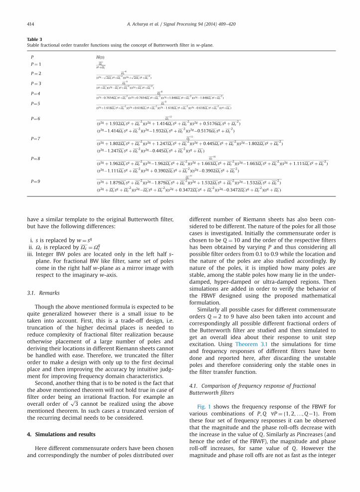
Table 3Stable fractional order transfer functions using the concept of Butterworth filter in w-plane.
P HðsÞP ¼ 1 Ωc
sqþΩc
P ¼ 2 Ωc4
ðs2q�ffiffi2
pΩc sqþΩc
2 Þðs2qþffiffi2
pΩc sqþΩc
2 Þ
P ¼ 3 Ωc5
ðsqþΩc Þðs2q�Ωc sqþΩc2 Þðs2qþΩc sqþΩc
2 Þ
P¼4 Ωc8
ðs2q�0:7654Ωc sqþΩc2 Þðs2qþ0:7654Ωc sqþΩc
2 Þðs2qþ1:848Ωc sqþΩc2 Þðs2q�1:848Ωc sqþΩc
2 Þ
P¼5 Ωc9
ðs2qþ1:618Ωc sqþΩc2 Þðs2qþ0:618Ωc sqþΩc
2 Þðs2q�1:618Ωc sqþΩc2 Þðs2q�0:618Ωc sqþΩc
2 ÞðsqþΩc Þ
P¼6 Ωc12
ðs2q þ 1:932Ωc sq þΩc2Þðs2q þ 1:414Ωc sq þΩc
2Þðs2q þ 0:5176Ωc sq þΩc2Þ
ðs2q�1:414Ωc sq þΩc2Þðs2q�1:932Ωc sq þΩc
2Þðs2q�0:5176Ωc sq þΩc2Þ
P¼7 Ωc13
ðs2q þ 1:802Ωc sq þΩc2Þðs2q þ 1:247Ωc sq þΩc
2Þðs2q þ 0:445Ωc sq þΩc2Þðs2q�1:802Ωc sq þΩc
2Þðs2q�1:247Ωc sq þΩc
2Þðs2q�0:445Ωc sq þΩc2Þðsq þΩc Þ
P¼8 Ωc16
ðs2q þ 1:962Ωc sq þΩc2Þðs2q�1:962Ωc sq þΩc
2Þðs2q þ 1:663Ωc sq þΩc2Þðs2q�1:663Ωc sq þΩc
2Þðs2q þ 1:111Ωc sq þΩc2Þ
ðs2q�1:111Ωc sq þΩc2Þðs2q þ 0:3902Ωc sq þΩc
2Þðs2q�0:3902Ωc sq þΩc2Þ
P¼9Ωc
17
ðs2q þ 1:879Ωc sq þΩc2Þðs2q�1:879Ωc sq þΩc
2Þðs2q þ 1:532Ωc sq þΩc2Þðs2q�1:532Ωc sq þΩc
2Þðs2q þΩc sq þΩc
2Þðs2q�Ωc sq þΩc2Þðs2q þ 0:3472Ωc sq þΩc
2Þðs2q�0:3472Ωc sq þΩc2Þðsq þΩc Þ
A. Acharya et al. / Signal Processing 94 (2014) 409–420414
have a similar template to the original Butterworth filter,but have the following differences:
i.
s is replaced by w¼ sqii.
Ωc is replaced by Ωc ¼Ωqciii.
Integer BW poles are located only in the left half s-plane. For fractional BW like filter, same set of polescome in the right half w-plane as a mirror image withrespect to the imaginary w-axis.3.1. Remarks
Though the above mentioned formula is expected to bequite generalized however there is a small issue to betaken into account. First, this is a trade-off design, i.e.truncation of the higher decimal places is needed toreduce complexity of fractional filter realization becauseotherwise placement of a large number of poles andderiving their locations in different Riemann sheets cannotbe handled with ease. Therefore, we truncated the filterorder to make a design with only up to the first decimalplace and then improving the accuracy by intuitive judg-ment for improving frequency domain characteristics.
Second, another thing that is to be noted is the fact thatthe above mentioned theorem will not hold true in case offilter order being an irrational fraction. For example anoverall order of
ffiffiffi3
pcannot be realized using the above
mentioned theorem. In such cases a truncated version ofthe recurring decimal needs to be considered.
4. Simulations and results
Here different commensurate orders have been chosenand correspondingly the number of poles distributed over
different number of Riemann sheets has also been con-sidered to be different. The nature of the poles for all thosecases is investigated. Initially the commensurate order ischosen to be Q ¼ 10 and the order of the respective filtershas been obtained by varying P and thus considering allpossible filter orders from 0.1 to 0.9 while the location andthe nature of the poles are also studied accordingly. Bynature of the poles, it is implied how many poles arestable, among the stable poles how many lie in the under-damped, hyper-damped or ultra-damped regions. Thensimulations are added in order to verify the behavior ofthe FBWF designed using the proposed mathematicalformulation.
Similarly all possible cases for different commensurateorders Q ¼ 2 to 9 have also been taken into account andcorrespondingly all possible different fractional orders ofthe Butterworth filter are studied and then simulated toget an overall idea about their response to unit stepexcitation. Using Theorem 3.1 the simulations for timeand frequency responses of different filters have beendone and reported here, after discarding the unstablepoles and therefore considering only the stable ones inthe filter transfer function.
4.1. Comparison of frequency response of fractionalButterworth filters
Fig. 1 shows the frequency response of the FBWF forvarious combinations of P;Q ∀P ¼ 1;2;…;Q�1f g. Fromthese four set of frequency responses it can be observedthat the magnitude and the phase roll-offs decrease withthe increase in the value of Q . Similarly as Pincreases (andhence the order of the FBWF), the magnitude and phaseroll-off increases, for same value of Q . However themagnitude and phase roll offs are not as fast as the integer

Fig. 1. Bode diagram of various orders of Fractional Butterworth like Filters with unit cut-off frequency for different values of Q.
A. Acharya et al. / Signal Processing 94 (2014) 409–420 415
order filters. This typical phenomenon helps to meetdesign specifications precisely and obtain an accuratefiltering action as required. In the simulation examples,the term ‘order’ of the FBWF represents the value P,determining the number of poles in the w-plane, whichis independent of the commensurate order Q .
4.2. Step response comparison
Fig. 2 shows the time response of the fractional orderBW filters whose Bode diagrams are shown in Fig. 1. Insecond order FO BW filter due to the co-existence ofunder-damped and hyper-damped poles made the curveto have oscillatory behavior for Q ¼ 3. Whereas, in thirdorder FBWF the co-existence of 2 under-damped, 2 hyper-damped and 1 critically damped pole made the stepresponse to have local oscillations (due to the under-damped pole) but not let the step response magnitudeexceed unity at all times. As we know that such ultra-damped poles cause extreme sluggishness in the stepresponse [25] but exhibits local oscillations instead of amonotonic step response due to having two under-damped poles for Q ¼ 3. Similarly for the fourth orderFBWF, co-existence of two under-damped poles and manyhyper-damped poles makes the system oscillatory forQ ¼ 3to7. For further higher values of Q , since the instabil-ity region and hence the under-damped region of theprimary Riemann sheet becomes more narrow, as a resultall the poles lie in the hyper-damped region indicating asluggish step response.
4.3. Pole locations of the FBW filter in complex w-plane
Fig. 3 shows the pole locations of the FBW filter in thew-plane for different commensurate orders. The first order(P ¼ 1) FBWF has one ultra-damped pole and is alwaysstable irrespective of the value of Q . The presence of theultra-damped pole implies a very sluggish time responsewhen the filter is subjected to a unit step input. A secondorder (P ¼ 2) FBWF has two under-damped and two hyper-damped poles which are always stable for all integervalues of Q . It can be seen that two of the poles lie onthe right half w-plane, but they are still outside theangular sector of instability 7qπ=2. The third order FBWFfilter has two under-damped, two hyper-damped and oneultra-damped poles. Similar to the previous case, it isalways stable for all integer values of Q . The fourth orderFBWF has four under-damped and four hyper-dampedpoles. However unlike the previous cases, the transferfunction given in Table 3 is only stable for Q43. For Q ¼ 2and Q ¼ 3, one unstable pair of poles should be excludedto obtain the filter transfer function. The fifth order casehas four under-damped, four hyper-damped poles and oneultra-damped pole. It is stable for Q42. For Q ¼ 2, the oneunstable pair of poles must be excluded to obtain a stablefilter transfer function. For the sixth order case six under-damped and six hyper-damped poles are there. The filter isstable for Q45. For Q ¼ 2to5, the one unstable pair ofpoles must be excluded to obtain the filter transfer func-tion. The seventh order case has six under-damped, sixhyper-damped poles and one ultra-damped pole. The filter

Fig. 2. Step response of various orders of fractional Butterworth like filter with unit cut-off frequency for different values of Q.
A. Acharya et al. / Signal Processing 94 (2014) 409–420416
is stable for Q43. For Q ¼ 2and Q ¼ 3, the one unstablepair of poles must be excluded to obtain the filter transferfunction. In the eighth order case, there are eight under-damped and eight hyper-damped poles. The filter is stablefor Q . For Q ¼ 2to5, the one unstable pair of poles must beexcluded to obtain the filter transfer function. It is alsoobserved that another pair of poles falls within theinstability region for Q ¼ 2. Thus for the eighth orderFBWF with Q ¼ 2, two pairs of unstable poles have to beexcluded and the resulting transfer function has to beobtained. For ninth order BW filter a much simpler casecan be observed where only one set of unstable poles haveto be excluded for Q ¼ 2to4. This filter has the samenumber of under-damped and hyper-damped poles forQ ¼ 2 as in the eighth order case, in addition with an ultra-damped pole. It is always stable for Q44. It is to be notedthat odd order of FBWF yields an ultra-damped pole whichproduces high sluggishness in the step response, whereas,with the even orders such oscillations are avoided. Asmentioned above, it can be seen that for higher values of P(higher than 3), some of the conjugate pairs are unstablefor low Q but stable for other higher values of Q . In suchcases the stability check using (6) must be done and theunstable pair of poles needs to be discarded.
It is also interesting to note that the poles of thefractional order filter are equi-spaced in complex w-planeand also stable which has not been done by contemporaryresearchers. As conventionally followed in the fractionalorder control community, we must consider the w-plane
stability notion or Matignon′s theorem to verify that thepoles of the filter fall in the stable region and also areequally distributed in w-plane.
5. Design advantages of fractional Butterworth filter
Generally, when a filter is to be designed it is expectedto meet certain frequency domain design specifications.There are four major specifications to be dealt with, whiledesigning an analog Butterworth filter. The frequency forthe end of the pass band (Ωp) and the start of the stopband (Ωs) are specified and hence the starting and endingfrequencies of the transition band are also specifiedbeforehand. Then the maximum pass band attenuation(αp) and minimum stop band attenuation (αs) are alsospecified. In order to design a BW filter which meets allthese specifications, the required order of the filter needsto be chosen first [26]. It can easily be obtained that giventhese specifications the exact order of the filter in terms ofthese specifications is given as eq. (14)
N¼log
ffiffiffiffiffiffiffiffiffiffiffiffiffiffiffiffiffiffiffiffiffiffiffiffiffiffiffiffiffiffiffiffiffiffiffiffiffiffiffiffiffiffiffiffiffiffiffið100:1αs�1=100:1αp�1Þ
qlogðΩs=ΩpÞ
ð14Þ
Also, the cut-off frequency (Ωc) can be calculated fromthe specification of the stop-band (Ωs) using the following

Fig. 3. Pole zero map of various orders of Butterworth filter in complex w-plane for different Q values.
A. Acharya et al. / Signal Processing 94 (2014) 409–420 417
relation.
Ωc ¼ Ωs
ð100:1αs�1Þ1=2Nð15Þ
Obviously it can be deduced that the value of Ncannotalways take integer values. In most cases it is more likelyto take fractional values. So in the traditional integer ordercase, we had to over satisfy the design needs. For example,if a filter of order 1.5 was required in order to exactly meetthe given specifications, a second order filter had to bedesigned. This can be overcome by fractional filter of anorder exactly equal to 1.5. As mentioned before in order todesign a filter of order 1.5, a 0.5 order filter can becascaded with a first order filter. One realistic designexample is illustrated here and supported with MATLABbased simulation studies.
5.1. Realistic design example
Suppose given the specifications that the maximumpass band attenuation be 0.5 dB and minimum stop bandattenuation be 20 dB. The pass band and stop band edgefrequencies are given as 2 rad/s and 3 rad/s. It is desired torealize a fractional order Butterworth like filter using theproposed technique.
Hence as from the given specifications αp ¼ 6 dB,αs ¼ 20 dB, Ωp ¼ 2 rad=s, Ωs ¼ 3 rad=s [26]. Thus the
desired order of the filter required is N¼ 4:3195. Truncat-ing up to one decimal place the order of the filter can beapproximated as N¼ 4:3. But from the convention ofinteger order BW filters, we had to over satisfy therequirements and design a filter of order 5. But using theproposed concept of FBW filter, we can now design a BWfilter having an integer and a fractional part, having anexact order of 4.3. In the design process, the nominalfractional part has been represented as a ratio of twointegers with no common factors i.e. P=Q ¼ 3=10 for ourcase. Here it is worth noticing that a filter of order 4.3could have been designed which has 43 poles distributedover 10 Riemann sheets. But in such cases the number ofunstable poles would have increased and as such nogeneralization can be possible like that reported inTables 2 and 3. Therefore in order to keep simplicity, it ispreferable that the nominal integer and fractional parts aredesigned separately using the respective concepts ofdesigning BW polynomial in corresponding s-plane or w-plane and construct filters using stable poles only and thencascade these two parts. Here, we have taken a similarapproach and put a FBWF of order 0.3 in cascaded with a4th order conventional BW filter.
For the integer order part (N¼ 4) it is found using (15)that ΩN ¼ 4
c ¼ 1:6891 rad/s. For conventional integer orderdesign the next integer value is used i.e. N¼ 5 and in thatcase the cut-off frequency ΩN ¼ 5
c ¼ 1:8948 rad/s. For
A. Acharya et al. / Signal Processing 94 (2014) 409–420418
integer order design the conventional 4th and 5th orderButterworth filter transfer functions are
HN ¼ 4ðsÞ ¼8:1408
s4 þ 4:4144s3 þ 9:7422s2 þ 12:5952sþ 8:1408ð16Þ
HN ¼ 5 sð Þ ¼ 24:4224s5 þ 6:1315s4 þ 18:7979s3 þ 35:6178s2 þ 41:7099sþ 24:4224
ð17Þ
For the fractional order part, the cut-off frequency getsmodified due to the mapping of the radius from s-plane tow-plane as Ωc ¼Ωq
c , where, Ωcis the obtained from conven-tional third order Butterworth filter design as ΩC ¼ ðΩP=
ð100:1αP �1Þð1=2PÞÞ with P ¼ 3. The Ωcobtained here corre-sponds to the s-plane. This has to be transformed into the w-plane in order to design fractional filters and will thusbecome Ωc ¼Ωq
c . It has been found that for P ¼ 3, Ωc isgreater than 1. Thus the circle on which the poles lie, will getsqueezed on transformation from the s-plane to the w-planeusing Eq. (13).
The nominal fractional part of the BW like filter isfound out to be of the form as given in Eq. (18) using thestandard notion of designing a third order BW filter but inthe transformed w-plane.
HN ¼ 0:3ðsÞ ¼1:181
s0:5 þ 1:0338s0:4 þ 1:0688s0:3 þ 1:105s0:2 þ 1:1424s0:1 þ 1:181
ð18Þ
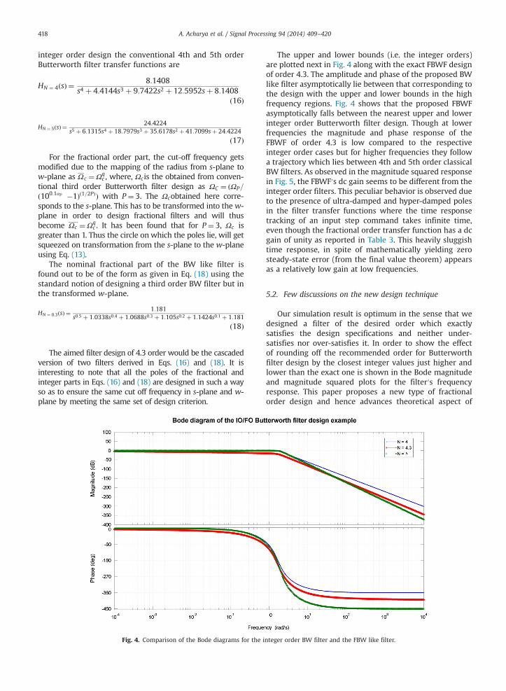
The aimed filter design of 4.3 order would be the cascadedversion of two filters derived in Eqs. (16) and (18). It isinteresting to note that all the poles of the fractional andinteger parts in Eqs. (16) and (18) are designed in such a wayso as to ensure the same cut off frequency in s-plane and w-plane by meeting the same set of design criterion.
Fig. 4. Comparison of the Bode diagrams for the i
The upper and lower bounds (i.e. the integer orders)are plotted next in Fig. 4 along with the exact FBWF designof order 4.3. The amplitude and phase of the proposed BWlike filter asymptotically lie between that corresponding tothe design with the upper and lower bounds in the highfrequency regions. Fig. 4 shows that the proposed FBWFasymptotically falls between the nearest upper and lowerinteger order Butterworth filter design. Though at lowerfrequencies the magnitude and phase response of theFBWF of order 4.3 is low compared to the respectiveinteger order cases but for higher frequencies they followa trajectory which lies between 4th and 5th order classicalBW filters. As observed in the magnitude squared responsein Fig. 5, the FBWF′s dc gain seems to be different from theinteger order filters. This peculiar behavior is observed dueto the presence of ultra-damped and hyper-damped polesin the filter transfer functions where the time responsetracking of an input step command takes infinite time,even though the fractional order transfer function has a dcgain of unity as reported in Table 3. This heavily sluggishtime response, in spite of mathematically yielding zerosteady-state error (from the final value theorem) appearsas a relatively low gain at low frequencies.
5.2. Few discussions on the new design technique
Our simulation result is optimum in the sense that wedesigned a filter of the desired order which exactlysatisfies the design specifications and neither under-satisfies nor over-satisfies it. In order to show the effectof rounding off the recommended order for Butterworthfilter design by the closest integer values just higher andlower than the exact one is shown in the Bode magnitudeand magnitude squared plots for the filter′s frequencyresponse. This paper proposes a new type of fractionalorder design and hence advances theoretical aspect of
nteger order BW filter and the FBW like filter.

Fig. 5. Magnitude squared function for the IO/BW filter design example.
A. Acharya et al. / Signal Processing 94 (2014) 409–420 419
solving the problem. The choice of the filter orders can bedone in future works by minimizing some performanceobjective and using intelligent optimization algorithms asdone in [27].
Also, after obtaining the FBWF, each FO operator can beapproximated using well-established analog or digitalrealization techniques [2]. Since the main goal of the FBWFdesign is to match the magnitude response, the well-known Charef′s method [28] may be easily applied sincethis technique matches the magnitude roll-off with smallpiecewise linear operators. For digital realization the FOfilter may be expanded using continued fraction expansion(CFE) and power series expansion (PSE) after discretizingthe filter using Euler, Tustin or Al-Alaoui rule [29]. In thepresent paper, the attempt was to have analog domainrealization of FBWF. We adopted the approach of designingin w-plane and then retrofitting into s-plane. The z-planediscretization is a further development, where the frac-tional order theory of stability has to be extended, in a newway. This discretization, in z-plane, will not be so direct-vis-à-vis w-plane and needs further exploration. Also, asan extension of the present work, the analog FBWF can betransformed to design high-pass, band-pass and band-stopfilters from the low-pass design, as done conventionally,since the fractional order operators are linear in nature.
6. Conclusion
A new kind of fractional Butterworth like filter has beendesigned using the consideration of poles lying on a circle inthe transformedw-plane and also using concept of stability incomplex w-plane. The obtained FBWFs are analyzed from thenature of poles, as well as in the time and frequency domain.The new fractional filter design technique is capable of meet-ing the design specifications in an exact manner rather thanunder or over satisfying it. This has been possible by making
the filter′s order exactly as per the design requirementswithout rounding-off to the nearest upper or lower integer.A practical design example has been given to show thepracticability of the proposed design technique. Future scopeof research can be directed towards extending the presentconcept for discrete domain filtering techniques which hashigher flexibility of realization using digital signal processors.Also, the concept can be extended for other class of FO IIRfilters and optimization of the filter orders with optimizationalgorithms as done in [27] can also be done in future.
References
[1] Shantanu Das, Functional Fractional Calculus, Springer, 2011.[2] Saptarshi Das, Indranil Pan, Fractional Order Signal Processing:
Introductory Concepts and Applications, Springer, 2011.[3] YangQuan Hu Sheng, Chen, TianShuang Qiu, Fractional Processes
and Fractional-order Signal Processing: Techniques and Applica-tions, Springer, 2011.
[4] A.G. Radwan, A.M. Soliman, A.S. Elwakil, First-order filters general-ized to the fractional domain,, Journal of Circuits, Systems, andComputers 17 (01) (2008) 55–66.
[5] A.G. Radwan, A.S. Elwakil, A.M. Soliman, On the generalization ofsecond-order filters to the fractional-order domain, Journal ofCircuits, Systems, and Computers 18 (02) (2009) 361–386.
[6] Yan Li, Hu Sheng, YangQuan Chen, Analytical impulse response of afractional second order filter and its impulse response invariantdiscretization, Signal Processing 91 (3) (2011) 498–507.
[7] A. Soltan, A.G. Radwan, A.M. Soliman, Butterworth passive filter inthe fractional-order, in: Microelectronics (ICM), 2011 InternationalConference on, December 2011, Hammamet, pp. 1–5.
[8] Denis Matignon, Stability results for fractional differential equationswith applications to control processing, Computational Engineeringin Systems Applications 2 (1996) 963–968.
[9] A.G. Radwan, A.M. Soliman, A.S. Elwakil, A. Sedeek, On the stabilityof linear systems with fractional-order elements, Chaos, Solitons &Fractals 40 (5) (2009) 2317–2328.
[10] B. Maundy, A.S. Elwakil, T.J. Freeborn, On the practical realization ofhigher-order filters with fractional stepping, Signal Processing 91 (3)(2011) 484–491.

A. Acharya et al. / Signal Processing 94 (2014) 409–420420
[11] T.J. Freeborn, B. Maundy, A.S. Elwakil, Field programmable analoguearray implementation of fractional step filters, IET Circuits, Devices &Systems 4 (6) (2010) 514–524.
[12] Ahmed Gomaa Radwan, Ahmed S. Elwakil, Ahmed M. Soliman,Fractional-order sinusoidal oscillators: design procedure and practicalexamples, IEEE Transactions on Circuits and Systems I: Regular Papers 55(7) (2008) 2051–2063.
[13] A.G. Radwan, A.M. Soliman, A.S. Elwakil, Design equations forfractional-order sinusoidal oscillators: four practical circuit exam-ples, International Journal of Circuit Theory and Applications 36 (4)(2008) 473–492.
[14] Brent Maundy, Ahmed Elwakil, Stephen Gift, On a multivibrator thatemploys a fractional capacitor, Analog Integrated Circuits and SignalProcessing 62 (1) (2010) 99–103.
[15] S. Butterworth, On the theory of filter amplifiers, Wireless Engineer7 (1930) 536–541.
[16] Farshad Merrikh-Bayat, Mahdi Afshar, Masoud Karimi-Ghartemani,Extension of the root-locus method to a certain class of fractional-order systems, ISA Transactions 48 (1) (2009) 48–53.
[17] Ivo Petrás, Stability of fractional-order systems with rational orders:a survey, Fractional Calculus & Applied Analysis 12 (3) (2009)269–298.
[18] Thomas Kailath, Ali H. Sayed, Babak Hassibi, Linear Estimation,Prentice Hall, Upper Saddle River, New Jersey, 2000.
[19] Dan Simon, Optimal State Estimation: Kalman, H1, and NonlinearApproaches, John Wiley & Sons, Hoboken, New Jersey, 2006.
[20] Peng Xiaojie Su, Ligang Shi, Wu, Yong-Duan Song, A novel approachto filter design for T–S fuzzy discrete-time systems with time-varying delay, IEEE Transactions on Fuzzy Systems 20 (6) (2012)1114–1129.
[21] Ligang Wu, Peng Shi, Huijun Gao, Changhong Wang, H1 filtering for2D Markovian jump systems, Automatica 44 (7) (2008) 1849–1858.
[22] D. Matignon,B.D.A. Novel, Observer-based controllers for fractionaldifferential systems, in: Proceedings of the 36th IEEE Conference onDecision and Control, 1997, vol. 5, December 1997, San Diego, CA,pp. 4967–4972.
[23] Saptarshi Das, Sumit Mukherjee, Shantanu Das, Indranil Pan,Amitava Gupta, Continuous order identification of PHWR modelsunder step-back for the design of hyper-damped power trackingcontroller with enhanced reactor safety, Nuclear Engineering andDesign 257 (2013) 109–127.
[24] Suman Saha, Saptarshi Das, Shantanu Das, Amitava Gupta, A con-formal mapping based fractional order approach for sub-optimaltuning of PID controllers with guaranteed dominant pole placement,Communications in Nonlinear Science and Numerical Simulations17 (9) (2012) 3628–3642.
[25] Tom T. Hartley, Carl F. Lorenzo, Dynamics and control of initializedfractional-order systems, Nonlinear Dynamics 29 (1) (2002)201–233.
[26] D.G. Manolakis, V.K. Ingle, Applied Digital Signal Processing: Theoryand Practice, Cambridge University Press, 2011.
[27] Anindya Pakhira, Saptarshi Das, Anish Acharya, Indranil Pan, SumanSaha, Optimized quality factor of fractional order analog filters withband-pass and band-stop characteristics, in: 2012 Third Interna-tional Conference on Computing, Communication and NetworkingTechnologies, ICCCNT 2012, art no. 6396000, July 2012, Coimbatore,doi: 10.1109/ICCCNT.2012.6396000.
[28] A. Charef, H.H. Sun, Y.Y. Tsao, B. Onaral, Fractal system as repre-sented by singularity function, IEEE Transactions on AutomaticControl 37 (9) (1992) 1465–1470.
[29] YangQuan Chen, Ivo Petras, Dingyu Xue, Fractional order control-atutorial, in: American Control Conference, ACC ’09, June 2009, St.Louis, MO, pp. 1397–1411.


![0750650842.Butterworth Heinemann.precast.concrete.structures.mar.2002 Slash Zero]](https://static.fdocuments.in/doc/165x107/5436f7d6219acd0f088b483a/0750650842butterworth-heinemannprecastconcretestructuresmar2002-slash-zero.jpg)
![Averroës decisive treatise [butterworth]](https://static.fdocuments.in/doc/165x107/5790572f1a28ab900c9c525b/averroes-decisive-treatise-butterworth.jpg)


![Fractional Cascading Fractional Cascading I: A Data Structuring Technique Fractional Cascading II: Applications [Chazaelle & Guibas 1986] Dynamic Fractional.](https://static.fdocuments.in/doc/165x107/56649ea25503460f94ba64dd/fractional-cascading-fractional-cascading-i-a-data-structuring-technique-fractional.jpg)