Extended MAPLA troubleshooting - gts-generator.com · 12V DC-power supply (approx. 10W power)....
15
GTS Generator. Technik. Systeme. GmbH & Co.KG Telefon: +49 (0) 7174 / 898 00%0 eMail: info@gts%generator.com Extended MAPLA troubleshooting page - 1 - editor: GTS version date: 17.06.2013 How to Check the GTS MAPLA – additional information Warning: At first observe strictly the safety information at the operating instructions. Beware of high voltage direct current up to 380VDC! The following instruction refers to the old MAPLA system. If you have an INT = iMAPLA system it is recommended to read out the MMI error flash code (MMI indications) at first. The troubleshooting of an iMAPLA system is quite similar to the old MAPLA system. First see in the operating instructions at page 75 – 4.9 Troubleshooting If an overload condition occurs (LED No. 5 lights): For further information you look in the operating instructions at page 75 (troubleshooting procedure). An overload condition occurs, if the magnet plate is oversized or damaged by taking a too high magnet current. At first check the resistance of the magnet plate. Ensure that the magnet plate is unplugged. Check the result with the following resistance table: GTS MAPLA System Watts rated Voltage max. Amps maximum allowed magnet plate resistance (minimum load) minimum allowed magnet plate resistance at 20°C / 68°F min. insulation resistance in Ohms 8 KW Magnet System 8.000 230 35 45 7,6 50.000 9 KW Magnet System 9.000 230 39 45 6,8 50.000 11 KW Magnet System 11.000 230 48 45 5,5 50.000 13 KW Magnet System 13.000 230 57 45 4,7 50.000 17 KW Magnet System 17.000 230 74 45 3,6 50.000 20 KW Magnet System 20.000 230 87 23 3,0 50.000 25 KW Magnet System 25.000 230 109 23 2,4 50.000 30 KW Magnet System 30.000 230 130 23 2,0 50.000 Magnet plate resistance for GTS systems (actual MAPLA) If the resistance is undersized, take a smaller magnet plate (with a higher resistance) and connect it to the generator system. Check the System again and measure the magnet current. Note: A warm plate has a higher resistance than a plate at 20°C / 68°F. If the resistance is normal or higher than allowed, check the magnet plate with the high voltage megaohmmeter. Ensure that the magnet plate is unplugged from the machine. If the resistance between the case and the active conductor is less than 50 KiloOhms the magnet plate is damaged. The rated insulation resistance of a new plate is higher than 500 KiloOhms. If an short circuit condition occurs (LED No. 5 flashes): For further information you look in the operating instructions at page 75 (troubleshooting procedure). A to high current (short current) causes a cut-off of the generator immediately. This is necessary to protect the electronic, the generator and the cables against overloads. If it is the first time you start up the system, check the pin assignment at output for magnet plate. black gray brown blue 1 1 2 2
Transcript of Extended MAPLA troubleshooting - gts-generator.com · 12V DC-power supply (approx. 10W power)....

GTS Generator. Technik. Systeme. GmbH & Co.KG Telefon: +49 (0) 7174 / 898 00%0 eMail: info@gts%generator.com
Extended MAPLA troubleshooting
page - 1 - editor: GTS version date: 17.06.2013
How to Check the GTS MAPLA – additional information
Warning: At first observe strictly the safety information at the operating instructions. Beware of high voltage direct current up to 380VDC!
The following instruction refers to the old MAPLA system. If you have an INT = iMAPLA system it is recommended to read out the MMI error flash code (MMI indications) at first. The troubleshooting of an iMAPLA system is quite similar to the old MAPLA system.
First see in the operating instructions at page 75 – 4.9 Troubleshooting
If an overload condition occurs (LED No. 5 lights): For further information you look in the operating instructions at page 75 (troubleshooting procedure). An overload condition occurs, if the magnet plate is oversized or damaged by taking a too high magnet current. At first check the resistance of the magnet plate. Ensure that the magnet plate is unplugged. Check the result with the following resistance table:
GTS MAPLA System Wattsrated
Voltagemax. Amps
maximum
allowed magnet
plate resistance
(minimum load)
minimum
allowed magnet
plate resistance
at 20°C / 68°F
min. insulation
resistance in
Ohms
8 KW Magnet System 8.000 230 35 45 7,6 50.000
9 KW Magnet System 9.000 230 39 45 6,8 50.000
11 KW Magnet System 11.000 230 48 45 5,5 50.000
13 KW Magnet System 13.000 230 57 45 4,7 50.000
17 KW Magnet System 17.000 230 74 45 3,6 50.000
20 KW Magnet System 20.000 230 87 23 3,0 50.000
25 KW Magnet System 25.000 230 109 23 2,4 50.000
30 KW Magnet System 30.000 230 130 23 2,0 50.000
Magnet plate resistance for GTS systems (actual MAPLA)
If the resistance is undersized, take a smaller magnet plate (with a higher resistance) and connect it to the generator system. Check the System again and measure the magnet current. Note: A warm plate has a higher resistance than a plate at 20°C / 68°F.
If the resistance is normal or higher than allowed, check the magnet plate with the high voltage megaohmmeter. Ensure that the magnet plate is unplugged from the machine. If the resistance between the case and the active conductor is less than 50 KiloOhms the magnet plate is damaged. The rated insulation resistance of a new plate is higher than 500 KiloOhms.
If an short circuit condition occurs (LED No. 5 flashes): For further information you look in the operating instructions at page 75 (troubleshooting procedure). A to high current (short current) causes a cut-off of the generator immediately. This is necessary to protect the electronic, the generator and the cables against overloads. If it is the first time you start up the system, check the pin assignment at output for magnet plate.
black
gray
brown
blue
1 1
2 2

GTS Generator. Technik. Systeme. GmbH & Co.KG Telefon: +49 (0) 7174 / 898 00%0 eMail: info@gts%generator.com
Extended MAPLA troubleshooting
page - 2 - editor: GTS version date: 17.06.2013
Note: To measure the insulation resistance by an insulation-monitor (optional for MAPLAs available)
the green/yellow wire should be connected to the magnet plate! Next check the magnet plate resistance (see above at overload condition). Further you have to check the power cable to the magnet plate against shorts and breaks or insulation errors. Perform a reset of the generator/system. If the fault occurs again, unplug the magnet power connector at the generator (only the connection to the magnet plate) and reset the system again. Start the generator and activate the magnet with the joystick button. If the LED No. 4 lights after a few seconds the MAPLA system is alright. If already the error exists (LED No. 5 flashes), the electronic has an internal fault. Change the electronic case at the generator and try again. You can check the power unit and the rectifier with a simple circuit analyzer (see below at page 2).
How to check the power unit (amplifier) and the rectifier in the electronic case: To test the power modules of the MAPLA take a rectifier analyzer to check the forward voltage of the discrete diodes. The description how to contact the MAPLA is written at page 7 and 8. At first you have to disconnect all connectors from the generator, the regulator and the magnet plate.
J1 / Pin Ux
J1 / Pin Vx
J1 / Pin Wx
J5 / Pin 5
J6
J1 / Pin Ux
J1 / Pin Vx
J1 / Pin Wx
J5 / Pin 5OUT1
OUT2
OUT1
OUT2J6
TEST RECTIFIERS TEST IGBT-MODULE
The forward voltage of the rectifier/diode is approx. 0,35V to 0,7V. If you have a breakdown of one diode, the forward voltage in both directions is 0,0V and so the power-module is damaged.
No power supply voltage for MMI available: Defect characteristics: The generator is running and active but the power supply LED No.1
at the MMI is off (does not light). Check the generator speed. The rated speed range of the generator is written in the default value table (see below at page 6). Build sizes of 132 need a minimum of 2800 rpm. Build sizes of 160 need a minimum of 2200 rpm. Check the exciter fuse, connected in row to the exciter line PIN1/F1 connected to the voltage regulators in the top of the case. Therefore you need only to open the case of the switch-box. If the exciter fuse is blown, it is recommended to change the voltage regulator and the fuse at the same time. GTS specifies to use a “Multicomp 3A slow blow 6.3x32mm 250V” type.
PIN J6 (in 8-17KW MAPLA)

GTS Generator. Technik. Systeme. GmbH & Co.KG Telefon: +49 (0) 7174 / 898 00%0 eMail: info@gts%generator.com
Extended MAPLA troubleshooting
page - 3 - editor: GTS version date: 17.06.2013
U1V1W1
U2V2W2�F2
+F1
Check the connections between the regulator, the generator and the electronic case. Check the MMI cable. Test the connection of every wire from the electronic case to the MMI. Check also the fuse of the MMI in the electronic case (see description below at page 7 and 8). Note: do not twist the fuse, only twist the cover to release the fuse Check the generator main winding resistance with an Ohmmeter. For it take the connection plan of the next picture (see below) and the default value table at page 6. If one of the results is out of the range, the generator could be damaged. It is also important, to check the insulation resistance of the stator main windings with a high voltage megohmmeter. Therefore you have to unplug the connector between the generator and the controller box. Ensure that you have no connection to the electronic case. The pin-connection of the generator is described at the two pictures below. Measure the insulation resistance with 500V (megohmmeter) between all connections and the case of the generator. If the resistance is less than 50KiloOhms the generator is damaged. The generator could also have lost the remanence (retentivity). If there is no rest of magnetism in the generator, the remanence voltage of the generator at idle running is less than 10VAC. This case causes that the regulator could not supply the exciting winding with current to build up the required magnetic field. Therefore the output voltage at the main machine is too low. You can check the remanence voltage of the generator. At first ensure that the generator is not rotating (stop the engine). Then you have to disconnect the connection of the generator to the electronic case. Ensure, that the regulator is disconnected. Take a voltmeter and set it to VAC-mode. Measure the voltage between the three phases U / V / W while you run the generator at the rated speed. The default remanence voltage range is written in table at page 6. MAPLA Generator 8KW to 20KW MAPLA Generator 25KW to 30KW
UV
W�F2
+F1
If the voltage is less than 10VAC, it is possible to rebuild the remanence. Stop the generator and take a 12V DC-power supply (approx. 10W power). Connect the pin +F1 with the +12V conductor and the –F2 pin with the ground (GND) conductor of the supply. A current of approx. 0,5A rebuilds the remanence in the generator (if it’s possible drive the generator with approx. 1500rpm). Supply the generator with this current only for 2-3 seconds. Following, check the remanence voltage between the phases again while the exciting current is again zero (no regulator connected).
GTS Generator. Technik. Systeme. GmbH & Co.KG Telefon: +49 (0) 7174 / 898 00%0 eMail: info@gts%generator.com
Extended MAPLA troubleshooting
page - 4 - editor: GTS version date: 17.06.2013
Not enough output voltage at the magnet plate: Defect characteristics: The generator is running and the output voltage at the magnet
plate is less than 200 VDC (result: not enough power). Check the generator speed. If the speed is less than the rated values in the default value table (see below) the generator is not able to supply the electronic with the required power. Check the connections between the regulator, the generator and the electronic case. Check the exciting voltage at ST1 between 1F1 & 1F2 (red and grey wire) with a voltmeter set to mode VDC. Note, that the voltmeter is able to measure “true-RMS”-voltages. Check the result with the default value table (see below). If the voltage is too high and the exciting current is higher than 2,0A the generator could be damaged (one of the rotating rectifiers). Next check the generator main winding resistance with an Ohmmeter. For it take the connection plan (see above) and the default value table at page 6. If one of the results is out of the range, the generator could be damaged. It is also able that one of the rotating diode in the generator is damaged. This causes a loss of exciting field (rotor) in the main machine of the generator. So we have only a weak magnetic field, which could not induce the rated voltage at the stator winding (power loss). In this case you can also check the exciting current of the regulator. If you have in a no load mode (magnet off) at the rated speed a low output voltage and the exciting current of the regulator is higher than 2,0ADC then it could be possible, that the exciter or one of the rectifier inside of the generator is damaged. To measure the exciting current, see the description at page 6.
Too high output voltage at the magnet plate: Defect characteristics: The generator rotating at rated speed generates a too high output voltage
to the magnet plate. The static voltage is higher than 250 Volt DC. (Note: The voltage to fast magnetisation is up to 280 Volt DC for
only 3-5 seconds after you have switched-on the magnet. The too high output voltage for a long time causes also a overload condition of the MAPLA System displayed with LED no. 5 at the MMI )
Check the impulse excitation interface ST2 (white wires) to the regulator connected to the MAPLA electronic. By a contact fault, the output voltage of the generator is constant higher than 275Volt DC. Check the voltage between the three yellow wires at the regulator connection ST1. Between every conductor you have to measure the voltage of the three phases from the generator. Check the results with the default value table at page 6. If there is one phase missing, the measured actual value of the regulator is wrong. So the regulator set a too high exciting current to the generator. This causes the over voltage of the system.

GTS Generator. Technik. Systeme. GmbH & Co.KG Telefon: +49 (0) 7174 / 898 00%0 eMail: info@gts%generator.com
Extended MAPLA troubleshooting
page - 5 - editor: GTS version date: 17.06.2013
R1 = 20 OhmR2 = 20 Ohm
R3 = 20 OhmR4 = 20 Ohm
R1
R1
R2
R2
R3R3
R4
R4
R1 = 5 OhmR2 = 5 OhmR3 = 5 Ohm
R1 R1 R2R2 R3R3
Note:
in a 20KW systemonly two resistors
R1 & R2 are connected
Slow system / long drop time: Defect characteristics: The generator is rotating at rated speed but the load at the magnet plate
falls down very slowly. This causes a long cycle time.
First check the voltage at magnet plate. Ensure that the Mode-Switch is in A-Position (normal mode). After switch on (push the joystick-button) the magnet voltage should be 280VDC for 2-3 seconds. This phase is called fast-magnetisation (fast pick-up) with impact excitation. While the magnet is on the output voltage to the magnet should be 230VDC constant should be after 3 seconds (rated voltage of the magnet). If the magnet voltage is never 280VDC for a short time after switch on, check the voltage regulator contacts an also the connection of the interface ST2 (see pictures at page 7 and 8). In the drop phase (material falls down) the output voltage at the magnet should be negative for several times. The polarity of the output voltage is changed 5 times so achieve the elimination of the rest of magnetism at the magnet plate. If the discharger unit is damaged, the electronic box could not change the output voltage. This causes a slow drop cycle (takes a long time). To check the discharger resistances (see the pictures below) take a normal ohmmeter and check the resistance values. (20Ohms for every resistance in 8-17KW systems / 5Ohms for every resistance in 20-30KW systems) MAPLA Generator 8KW to 17KW MAPLA Generator 20KW to 30KW

GTS Generator. Technik. Systeme. GmbH & Co.KG Telefon: +49 (0) 7174 / 898 00%0 eMail: info@gts%generator.com
Extended MAPLA troubleshooting
page - 6 - editor: GTS version date: 17.06.2013
Default values of all GTS MAPLA - Systems:
generator (build size 132) 8KW 11KW / 13KW 17KW 20KW
resistance exciting winding at 20°C/68°F [Ohm]
resistance main stator winding U to V [Ohm] approx. 0,5 Ohms approx. 0,5 Ohms approx. 0,4 Ohms approx. 0,4 Ohms
resistance main stator winding V to W [Ohm] approx. 0,5 Ohms approx. 0,5 Ohms approx. 0,4 Ohms approx. 0,4 Ohms
resistance main stator winding W to U [Ohm] approx.0,5 Ohms approx.0,5 Ohms approx. 0,4 Ohms approx. 0,4 Ohms
generator speed range [rpm]
no load running mode
regulated generator voltage U to V [VAC] 175V to 185V 174V to 184V 179V to 187V 174V to 184V
regulated generator voltage V to W [VAC] 175V to 185V 174V to 184V 179V to 187V 174V to 184V
regulated generator voltage W to U [VAC] 175V to 185V 174V to 184V 179V to 187V 174V to 184V
remanence voltage between the every phase only if
the regulator is disconnected @ 3000rpm [VAC]30V to 70V 30V to 70V 30V to 70V 30V to 70V
exciting voltage at ST1 / 1F1 to 1F2 [VDC] 10V to 25V 6V to 20V 4V to 18V 10V to 25V
exciting current of the regulator [ADC] 0,3A to 0,6A 0,2A to 0,5A 0,2A to 0,5A 0,3A to 0,6A
load running mode
output voltage at the magnet plate [VDC]
maximum magnet current [ADC] 35A 47A (11KW) / 56A (13KW) 74A 87A
generator voltage U to V [VAC] 175V to 185V 172V to 184V 172V to 180V 174V to 183V
generator voltage V to W [VAC] 175V to 185V 172V to 184V 172V to 180V 174V to 183V
generator voltage W to U [VAC] 175V to 185V 172V to 184V 172V to 180V 174V to 183V
exciting voltage at ST1 / 1F1 to 1F2 [VDC] 15V to 40V 10V to 35V 10V to 40V 12V to 40V
exciting current of the regulator [ADC] 0,4A to 1,4A 0,3A to 1,4A 0,3A to 1,6A 0,4A to 1,8A
220V to 238V
24 Ohms to 26 Ohms
value range (measured @ 3000rpm)
value range (measured @ 3000rpm)
2850 rpm to 4000 rpm
generator (build size 160) 25KW / 30KW
resistance exciting winding at 20°C/68°F [Ohm] 27 Ohms to 28 Ohms
resistance main stator winding U1 to V1 [Ohm] approx. 0,3 Ohms
resistance main stator winding V1 to W1 [Ohm] approx. 0,3 Ohms
resistance main stator winding W1 to U1 [Ohm] approx. 0,3 Ohms
resistance main stator winding U2 to V2 [Ohm] approx. 0,3 Ohms
resistance main stator winding V2 to W2 [Ohm] approx. 0,3 Ohms
resistance main stator winding W2 to U2 [Ohm] approx. 0,3 Ohms
resistance main stator winding U1 to U2 [Ohm] high resistance >1MegaOhm
generator speed range [rpm] 2200 rpm to 3300 rpm
no load running mode value range (measured @ 2300rpm)
regulated generator voltage U to V [VAC] 155V to 170V
regulated generator voltage V to W [VAC] 155V to 170V
regulated generator voltage W to U [VAC] 155V to 170V
remanence voltage between the every phase only if
the regulator is disconnected @ 2300rpm [VAC]min. 30V to 70V
exciting voltage at ST1 / 1F1 to 1F2 [VDC] 5V to 20V
exciting current of the regulator [ADC] 0,2A to 0,5A
load running mode value range (measured @ 2300rpm)
output voltage at the magnet plate [VDC] 220V to 238V
maximum magnet current [ADC] 109A (25KW) / 130A (30KW)
generator voltage U to V [VAC] 170V to 180V
generator voltage V to W [VAC] 170V to 180V
generator voltage W to U [VAC] 170V to 180V
exciting voltage at ST1 / 1F1 to 1F2 [VDC] 8V to 30V
exciting current of the regulator [ADC] 0,3A to 1,4A
Note: The generator with build size 160 has two separate Y-wired main windings to supply the MAPLA electronic. The windings are separated with the no. 1 and 2.
To get the exciting current of the regulator, measure the exciting resistance (F1 to F2) and
the exciting voltage at ST1 (see connection plan at page 9 and 10). The current is calculated by voltage / resistance (divide).
Measuring of exciting voltage is possible only with a “True-RMS-Multimeter”

GTS Generator. Technik. Systeme. GmbH & Co.KG Telefon: +49 (0) 7174 / 898 00%0 eMail: info@gts%generator.com
Extended MAPLA troubleshooting
page - 7 - editor: GTS version date: 17.06.2013
1 Power supply voltage for MMI available The system is ON and ready for operation – the generator is running. 2 Magnet plate is on ("lifting") This LED remains on while the magnet plate is in the on state. If the magnet plate is switched off, i.e. the load is thrown off, this LED goes out. 3 Fast demagnetization in progress (“fast drop”) 3 (fast „throwing off“ only in normal mode / A-Mode) The LED is on during automatic fast demagnetization. The LED goes out after the demagnetization has been finished completely. This mode is disabled if inching mode* (optional mode B) is selected. 4 Open magnet connection / Data interface fault LED on: Open magnet connection / Interruption The LED light continues, if the connecting cable of the magnet plate is either not plugged in or interrupted. LED flashes: Data interface error The LED flashes, if a communication error has occurred on the data interface between MAPLA and MMI. Check the MMI data cable against electrical contact problems. 5 Overload / System failure LED on: Overload (magnet current limiter at INT-System active) The LED is on, if the connected magnet plate is oversized for the MAPLA system. In some cases the magnet plate could be damaged internally. At the new INT-System, the magnet current limiter is active. The magnet current is limited to the max. allowed value. The LED could also be light, if a very cold magnet is connected. After a few minutes while operation, the LED should be off. Otherwise the magnet should be checked. LED flashes: System failure (at older non INT-Systems: Short circuit) This LED flashes, if at an INT-System a system failure has occurred. To find out the exactly causation of this fault, a flash-code could be displayed at the 100%-LED and verified with a separate flash-code table. At older systems (non INT), the flashing LED means, you have a general short circuit. The magnet was switched off (cut-off) immediately. The problem should be checked by an electricity specialist. To reset the fault, an engine stop is required. 6 Underspeed / Overspeed LED on: Underspeed generator The LED is on, if the generator operates at underspeed and thus may no longer be able to realize its full performance (reduced voltage). LED flashes: Overspeed generator Flashing of this LED indicates that the generator operates at overspeed. The system / magnet is blocked to switch on again. May you need a reset of the system (stop engine). 7 Duty ratio of the magnet plate in percent The duty ratio of the magnet plate is the ratio between on-period and off-period. To protect the magnet plate (against over temperatures), the duty ratio should be less than 80%. Check also the max. allowed value for your used magnet. If the 100%-LED is flashing, it is required to take a break period! 4 + 5 + 6 LED flashing Insulation monitor alert The insulation monitor (optional) has detected an insulation error between the magnet plate case and the active conductor (+/-) of the MAPLA system. If these LEDs are flashing the resistance is less than 25 KiloOhms. It is required to check the system against insulation faults. At INT-Systems, the magnet is blocked to switch on again (reset required).
4 + 5 + 6 LED on + 7(100%) LED flashes Over temperature error of electronic / generator As long as this error is indicated, the magnet plate could not be switched on again after having thrown off the load. Once temperature of generator and electronic is within the tolerance limits again, the indicator will go out automatically. It is recommended to cool down the system while engine is running in idle mode. Check the system against dust and a covered or damaged generator fan!
Bxx INT xxxx
123456
variant INT: intelligent
MAPLA ( only at newer systems / at older systems these
three letters are missing )
max. power in KiloWatts
version/ type
GTS Generator. Technik. Systeme. GmbH & Co.KG Telefon: +49 (0) 7174 / 898 00%0 eMail: info@gts%generator.com
Extended MAPLA troubleshooting
page - 8 - editor: GTS version date: 17.06.2013
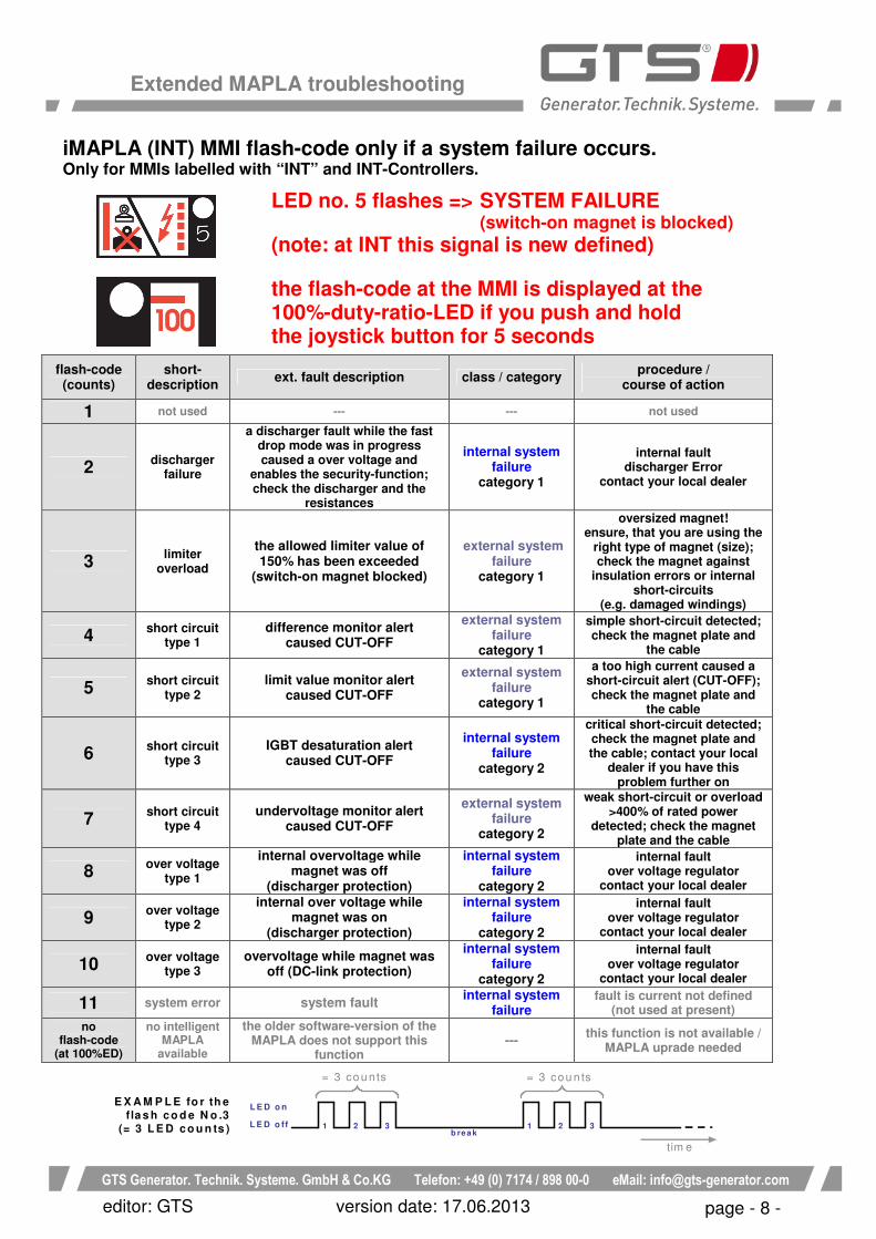
E X A M P L E fo r th efla s h c o d e N o .3
(= 3 L E D c o u n ts )
L E D o n
L E D o ffb re a k
1 2 3 1 2 3
= 3 co u n ts = 3 co u n ts
tim e
iMAPLA (INT) MMI flash-code only if a system failure occurs. Only for MMIs labelled with “INT” and INT-Controllers.
LED no. 5 flashes => SYSTEM FAILURE (switch-on magnet is blocked) (note: at INT this signal is new defined)
the flash-code at the MMI is displayed at the 100%-duty-ratio-LED if you push and hold the joystick button for 5 seconds
flash-code (counts)
short-description
ext. fault description class / category procedure /
course of action
1 not used --- --- not used
2 discharger
failure
a discharger fault while the fast drop mode was in progress caused a over voltage and
enables the security-function; check the discharger and the
resistances
internal system failure
category 1
internal fault discharger Error
contact your local dealer
3 limiter
overload
the allowed limiter value of 150% has been exceeded
(switch-on magnet blocked)
external system failure
category 1
oversized magnet! ensure, that you are using the
right type of magnet (size); check the magnet against
insulation errors or internal short-circuits
(e.g. damaged windings)
4 short circuit
type 1 difference monitor alert
caused CUT-OFF
external system failure
category 1
simple short-circuit detected; check the magnet plate and
the cable
5 short circuit
type 2 limit value monitor alert
caused CUT-OFF
external system failure
category 1
a too high current caused a short-circuit alert (CUT-OFF); check the magnet plate and
the cable
6 short circuit
type 3 IGBT desaturation alert
caused CUT-OFF
internal system failure
category 2
critical short-circuit detected; check the magnet plate and the cable; contact your local
dealer if you have this problem further on
7 short circuit
type 4 undervoltage monitor alert
caused CUT-OFF
external system failure
category 2
weak short-circuit or overload >400% of rated power
detected; check the magnet plate and the cable
8 over voltage
type 1
internal overvoltage while magnet was off
(discharger protection)
internal system failure
category 2
internal fault over voltage regulator
contact your local dealer
9 over voltage
type 2
internal over voltage while magnet was on
(discharger protection)
internal system failure
category 2
internal fault over voltage regulator
contact your local dealer
10 over voltage
type 3 overvoltage while magnet was
off (DC-link protection)
internal system failure
category 2
internal fault over voltage regulator
contact your local dealer
11 system error system fault internal system
failure fault is current not defined
(not used at present)
no flash-code
(at 100%ED)
no intelligent MAPLA
available
the older software-version of the MAPLA does not support this
function ---
this function is not available / MAPLA uprade needed

GTS Generator. Technik. Systeme. GmbH & Co.KG Telefon: +49 (0) 7174 / 898 00%0 eMail: info@gts%generator.com
Extended MAPLA troubleshooting
page - 9 - editor: GTS version date: 17.06.2013
Testing the MMI-Connections --- MMI LED and button descriptions (actual version)
Only if the jumper JP2 is not set
S1 S2
D16
D17
D15D14
D23
P1 P2
D35D34
JP2
J2
J1
JP2 Jumper to configure the respective hardware version to the programmed software of the MMI. Important: Do not change/set S1 Joystick test push button. To test the joystick switch, push this button and the magnet plate should be in on mode. Before you have to select the operational mode at the switch of the MMI (optional function). S2 Test button to change operational mode between normal mode and inching mode*. To test the inching mode* (mode B) push and hold this button. P1 & P2 Potentiometer for optional functions Important: Do not twist3 D14 signal LED joystick to J1 Only enabled if JP2 is set. D15 signal LED main-switch to J1 Only enabled if JP2 is set. D16 signal LED relay K1 on The LED D16 lights, if the magnet is in on mode (“lifting”). (not on some old software versions) D17 signal LED relay K2 on Only enabled if JP2 is set. D23 signal LED inching mode* to J1 (only available at new pcb-version and if JP2 is set) The LED D23 lights, if the MAPLA is in inching mode*. The signal for this configuration is connected to J1.
J1 Extented interface (optional) is active, if the jumper JP2 is set.
D34 signal LED joystick to J2 If the Joystick connected to J2 is pushed, the LED D34 is on.
J2 Data and power connection between the MMI and the control system (generator)
D35 signal LED inching mode* to J2 If the mode-switch (optional) at the MMI is in inching mode* (mode B), the LED D35 is on.

GTS Generator. Technik. Systeme. GmbH & Co.KG Telefon: +49 (0) 7174 / 898 00%0 eMail: info@gts%generator.com
Extended MAPLA troubleshooting
page - 10 - editor: GTS version date: 17.06.2013
Testing the MMI-Connections --- MMI LED and button descriptions (actual version)
Only if the jumper JP2 is set
S1 S2
D16
D17
D15D14
D23
P1 P2
D35D34
JP2
J2
J1
JP2 Jumper to configure the respective hardware version to the programmed software of the MMI. Important: Do not change/remove S2 Test button to activate the MAPLA To test the main-switch for the MAPLA push and hold this button. S1 Joystick test push button. To test the Joystick switch, push this button and the magnet plate should be in on mode. Before you have to activate the system with the switch S2 or main-switch at the machine panel. P1 & P2 Potentiometer for optional functions Important: Do not twist3 D14 signal LED joystick to J1 If the joystick button connected to J1 is pushed, the LED D14 should be on. D15 signal LED main-switch on If the main-switch at the machine panel is on, the LED D15 should be on. D16 signal LED relay K1 on The LED D16 lights, if the magnet is in on mode (“lifting”) D17 signal LED relay K2 on The LED D17 lights, if the main- switch at the panel is on. D23 signal LED inching mode* to J1 (only available at new pcb-version) The LED D23 lights, if the MAPLA is in inching mode*. The signal for this configuration is connected to J1. For this mode JP2 has to be set.
J1 Extented interface (optional) is active, if the jumper JP2 is set.
D34 signal LED joystick to J2 If the Joystick connected to J2 (optional) is pushed, the LED D34 is on. Important, if JP2 is not set.
J2 Data and power connection between the MMI and the control system (generator)
D35 signal LED inching mode* to J2 If the mode-switch (optional) at the MMI is in inching mode (mode B), the LED D35 is on.

GTS Generator. Technik. Systeme. GmbH & Co.KG Telefon: +49 (0) 7174 / 898 00%0 eMail: info@gts%generator.com
Extended MAPLA troubleshooting
page - 11 - editor: GTS version date: 17.06.2013
Connections of the MAPLA-System 8KW to 17KW:
ST2
Uact
to S
T1
OUT2
OUT1
MMI�Interface
J601
J5
J2
J1
MMI fuse
uuuuvv
vv wwww
1
1
2 23
34
4
Discharger
ISO
�Monit
or
ISO
�Monit
oru
v
w
1
2
1
2
34
5J6
GTS Generator. Technik. Systeme. GmbH & Co.KG Telefon: +49 (0) 7174 / 898 00%0 eMail: info@gts%generator.com
Extended MAPLA troubleshooting
page - 12 - editor: GTS version date: 17.06.2013
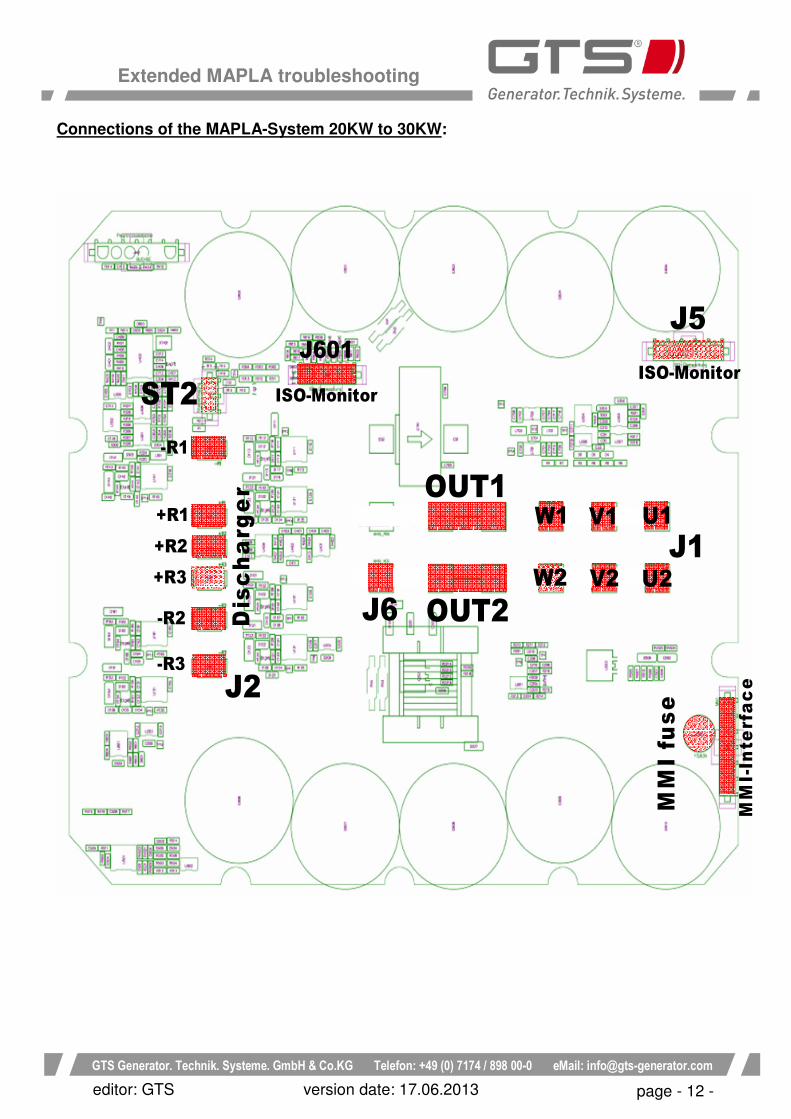
Connections of the MAPLA-System 20KW to 30KW:
OUT1
ISO�Monitor
ISO�Monitor
MM
I�In
terf
ac
e
MM
I fu
se
ST2
Dis
ch
arg
er
�R1
+R1
+R2
+R3
�R2
�R3
J5J601
J6 OUT2
W1
J1
J2
V1 U1
U2V2W2

GTS Generator. Technik. Systeme. GmbH & Co.KG Telefon: +49 (0) 7174 / 898 00%0 eMail: info@gts%generator.com
Extended MAPLA troubleshooting
page - 13 - editor: GTS version date: 17.06.2013
Overview / simple schematic of the iMAPLA–System G1 8KW to 17KW:

GTS Generator. Technik. Systeme. GmbH & Co.KG Telefon: +49 (0) 7174 / 898 00%0 eMail: info@gts%generator.com
Extended MAPLA troubleshooting
page - 14 - editor: GTS version date: 17.06.2013
Overview / simple schematic of the iMAPLA–System G1 20KW:

GTS Generator. Technik. Systeme. GmbH & Co.KG Telefon: +49 (0) 7174 / 898 00%0 eMail: info@gts%generator.com
Extended MAPLA troubleshooting
page - 15 - editor: GTS version date: 17.06.2013
Overview / simple schematic of the iMAPLA–System G1 25kW to 30KW: