ExtendAir® G2™ Digital Microwave Radios Installation and ...
129
208871-002 2014-05-27 ExtendAir ® G2™ Digital Microwave Radios Installation and Management Guide Models: rc07020 ITU/ETSI rc08020 ITU/ETSI rc11020 FCC rc11020 ITU/ETSI rc13020 ITU/ETSI rc15020 FCC rc15020 ITU/ETSI rc18020 FCC rc18020 ITU/ETSI rc23020 FCC rc23020 ITU/ETSI rc38020 FCC rc38020 ITU/ETSI
Transcript of ExtendAir® G2™ Digital Microwave Radios Installation and ...

208871-0022014-05-27
ExtendAir® G2™Digital Microwave Radios Installation
and Management Guide
Models:rc07020 ITU/ETSIrc08020 ITU/ETSI
rc11020 FCCrc11020 ITU/ETSIrc13020 ITU/ETSI
rc15020 FCCrc15020 ITU/ETSI
rc18020 FCCrc18020 ITU/ETSI
rc23020 FCCrc23020 ITU/ETSI
rc38020 FCCrc38020 ITU/ETSI

Exalt Installation and Management Guide
ExtendAir G2 Digital Microwave Radios
ii 208871-002
2014-05-27
Legal NoticeThe information contained herein is the property of Exalt Communications, Inc. (“Exalt”) and is supplied without liability for errors or omissions. No part of this document may be reproduced, in any form, except as authorized by contract or other written permission from the owner.
Any brand names and product names included in this manual are trademarks, registered trademarks, or trade names of their respective holders.
The contents of this document are current as of the date of publication. Exalt reserves the right to change the contents without prior notice.
The publication of information in this document does not imply freedom from patent or other rights of Exalt or others.
© 2014 Exalt Communications Inc. All rights reserved. The Exalt logo is a trademark of Exalt Communications, Inc. ExtendAir is a registered trademark of Exalt Communications Inc.
Open-Source License InformationPer the terms of your Exalt Limited Hardware Warranty, Software License, and RMA Procedures Agreement with Exalt Communications, Inc. and/or its subsidiaries, certain Third Party Software may be provided with and as part of the Exalt products provided to you, and any such Third Party Software files provided are governed by the terms of their separate Third Party Licenses, which licenses give you at least the license rights licensed to you in the Exalt End User Agreement and may give you additional license rights as to the Third Party Software, but only with respect to the particular Third Party Software to which the Third Party License applies.
The Exalt Products may include or be bundled with some or all of the following third party software. Copies of the copyright notices and license agreements for any or all of these may be requested by contacting Exalt support at email: [email protected].
Open Source Code License Agreement Website
Embedded Linux - OS U-Boot
Boot Code. Both licensed under GPL Version 3 www.gnu.org www.sourceforge.net
Busy Box Linux Commands. Licensed under GPL Version 2 www.gnu.org and www.busybox.net
Scew Expat Wrapper. Licensed under LGPL Version 3 www.gnu.org
OpenSSL SSL Web Access. Licensed under dual license www.openssl.org
Net-SNMP SNMP Agent. Licensed under NetSNMP (see Copyright Notices)
Dropbear SSH 2 Server; Expat - XML Parser; BarelyFitz – Java Script Tabifier; jQuery; and Flotr – Java Script Plotting Library. All of which are licensed under MIT License
www.opensource.org/licenses/mit-license.php
GoAhead Webserver Licensed under GoAhead License Agreement www.goahead.com

Exalt Installation and Management Guide
ExtendAir G2 Digital Microwave Radios
iii 208871-002
2014-05-27
Table of ContentsLegal Notice . . . . . . . . . . . . . . . . . . . . . . . . . . . . . . . . . . . . . . . . . . . . . . . . . . . . . . . . . . . . . . . iiOpen-Source License Information . . . . . . . . . . . . . . . . . . . . . . . . . . . . . . . . . . . . . . . . . . . . . . iiList of Figures . . . . . . . . . . . . . . . . . . . . . . . . . . . . . . . . . . . . . . . . . . . . . . . . . . . . . . . . . . . . viList of Tables . . . . . . . . . . . . . . . . . . . . . . . . . . . . . . . . . . . . . . . . . . . . . . . . . . . . . . . . . . . . . viiAbout this Document . . . . . . . . . . . . . . . . . . . . . . . . . . . . . . . . . . . . . . . . . . . . . . . . . . . . . . viii
Revision History . . . . . . . . . . . . . . . . . . . . . . . . . . . . . . . . . . . . . . . . . . . . . . . . . . . . . . viiiIcons . . . . . . . . . . . . . . . . . . . . . . . . . . . . . . . . . . . . . . . . . . . . . . . . . . . . . . . . . . . . . . . . viii
Introduction . . . . . . . . . . . . . . . . . . . . . . . . . . . . . . . . . . . . . . . . . . . . . . . . . . . . . . . . . . . . . . . 1Related Documentation and Software . . . . . . . . . . . . . . . . . . . . . . . . . . . . . . . . . . . . . . . . 1The ExtendAir G2 Digital Microwave Radios . . . . . . . . . . . . . . . . . . . . . . . . . . . . . . . . . 1Basic Features . . . . . . . . . . . . . . . . . . . . . . . . . . . . . . . . . . . . . . . . . . . . . . . . . . . . . . . . . . 3
Preinstallation Tasks . . . . . . . . . . . . . . . . . . . . . . . . . . . . . . . . . . . . . . . . . . . . . . . . . . . . . . . . 5Link Engineering and Site Planning . . . . . . . . . . . . . . . . . . . . . . . . . . . . . . . . . . . . . . . . . 5Familiarization with the ExtendAir G2 Radios . . . . . . . . . . . . . . . . . . . . . . . . . . . . . . . . . 5
Shipping Box Contents . . . . . . . . . . . . . . . . . . . . . . . . . . . . . . . . . . . . . . . . . . . . . . . . . 6Initial Configuration and Back-to-Back Bench Test . . . . . . . . . . . . . . . . . . . . . . . . . . . . . 6RF Output Power Setting . . . . . . . . . . . . . . . . . . . . . . . . . . . . . . . . . . . . . . . . . . . . . . . . . . 7Critical Configuration Considerations . . . . . . . . . . . . . . . . . . . . . . . . . . . . . . . . . . . . . . . . 8
Radio Reset . . . . . . . . . . . . . . . . . . . . . . . . . . . . . . . . . . . . . . . . . . . . . . . . . . . . . . . . . . 9Virtual Local Area Network (VLAN) . . . . . . . . . . . . . . . . . . . . . . . . . . . . . . . . . . . . . . . . 9Simple Network Management Protocol (SNMP) . . . . . . . . . . . . . . . . . . . . . . . . . . . . . . 10
System Installation and Initiation Process . . . . . . . . . . . . . . . . . . . . . . . . . . . . . . . . . . . . . . . 11Record Keeping . . . . . . . . . . . . . . . . . . . . . . . . . . . . . . . . . . . . . . . . . . . . . . . . . . . . . . . . 12
Installation . . . . . . . . . . . . . . . . . . . . . . . . . . . . . . . . . . . . . . . . . . . . . . . . . . . . . . . . . . . . . . . 13Mechanical Configuration and Mounting . . . . . . . . . . . . . . . . . . . . . . . . . . . . . . . . . . . . 13
Mounting the System . . . . . . . . . . . . . . . . . . . . . . . . . . . . . . . . . . . . . . . . . . . . . . . . . 13Radio Ports and Indicators . . . . . . . . . . . . . . . . . . . . . . . . . . . . . . . . . . . . . . . . . . . . . . . . 14
Connector Overview . . . . . . . . . . . . . . . . . . . . . . . . . . . . . . . . . . . . . . . . . . . . . . . . . . 15LED Indicators . . . . . . . . . . . . . . . . . . . . . . . . . . . . . . . . . . . . . . . . . . . . . . . . . . . . . . 16
Power . . . . . . . . . . . . . . . . . . . . . . . . . . . . . . . . . . . . . . . . . . . . . . . . . . . . . . . . . . . . . . . . 16Terminating the RF Connection . . . . . . . . . . . . . . . . . . . . . . . . . . . . . . . . . . . . . . . . . 17Applying Power . . . . . . . . . . . . . . . . . . . . . . . . . . . . . . . . . . . . . . . . . . . . . . . . . . . . . 17
CAT5e or CAT6 Lightning/Surge Protection . . . . . . . . . . . . . . . . . . . . . . . . . . . . . . . . . 17Diplexer (Channel Plan) Configuration . . . . . . . . . . . . . . . . . . . . . . . . . . . . . . . . . . . . . . 18Antenna/Transmission System . . . . . . . . . . . . . . . . . . . . . . . . . . . . . . . . . . . . . . . . . . . . 21
Initial Antenna Mounting . . . . . . . . . . . . . . . . . . . . . . . . . . . . . . . . . . . . . . . . . . . . . . 21Transmission Line from Antenna to Radio (Remote Mount). . . . . . . . . . . . . . . . . . . 22
Antenna Alignment . . . . . . . . . . . . . . . . . . . . . . . . . . . . . . . . . . . . . . . . . . . . . . . . . . . . . 23Configuration and Management . . . . . . . . . . . . . . . . . . . . . . . . . . . . . . . . . . . . . . . . . . . . . . 24
Command Line Interface (CLI) . . . . . . . . . . . . . . . . . . . . . . . . . . . . . . . . . . . . . . . . . . . . 24Telnet into the Command Line Interface (CLI) . . . . . . . . . . . . . . . . . . . . . . . . . . . . . . . . 24
Connect to the Radio in a Telnet Session . . . . . . . . . . . . . . . . . . . . . . . . . . . . . . . . . . 24Telnet . . . . . . . . . . . . . . . . . . . . . . . . . . . . . . . . . . . . . . . . . . . . . . . . . . . . . . . . . . . . . 24
Exalt Graphical User Interface (GUI) . . . . . . . . . . . . . . . . . . . . . . . . . . . . . . . . . . . . . . . 25Preparing to Connect . . . . . . . . . . . . . . . . . . . . . . . . . . . . . . . . . . . . . . . . . . . . . . . . . 25Make Connections . . . . . . . . . . . . . . . . . . . . . . . . . . . . . . . . . . . . . . . . . . . . . . . . . . . 26
Exalt Installation and Management Guide
ExtendAir G2 Digital Microwave Radios
208871-002 iv2014-05-27
Log In . . . . . . . . . . . . . . . . . . . . . . . . . . . . . . . . . . . . . . . . . . . . . . . . . . . . . . . . . . . . . 26Login Privileges . . . . . . . . . . . . . . . . . . . . . . . . . . . . . . . . . . . . . . . . . . . . . . . . . . . . . 26
Quick Start . . . . . . . . . . . . . . . . . . . . . . . . . . . . . . . . . . . . . . . . . . . . . . . . . . . . . . . . . . . . 27Navigating the GUI . . . . . . . . . . . . . . . . . . . . . . . . . . . . . . . . . . . . . . . . . . . . . . . . . . . . . 28
Summary Status Section . . . . . . . . . . . . . . . . . . . . . . . . . . . . . . . . . . . . . . . . . . . . . . . 29Navigation Panel. . . . . . . . . . . . . . . . . . . . . . . . . . . . . . . . . . . . . . . . . . . . . . . . . . . . . 30
Radio Information Page . . . . . . . . . . . . . . . . . . . . . . . . . . . . . . . . . . . . . . . . . . . . . . . . . . 31Administration Settings Page . . . . . . . . . . . . . . . . . . . . . . . . . . . . . . . . . . . . . . . . . . . . . . 32NTP and Time Zones Configurations Page . . . . . . . . . . . . . . . . . . . . . . . . . . . . . . . . . . . 34Simple Network Management Protocol (SNMP) Configuration . . . . . . . . . . . . . . . . . . . 35
SNMP v1/v2c/v3 Support Options . . . . . . . . . . . . . . . . . . . . . . . . . . . . . . . . . . . . . . . 36SNMP Traps . . . . . . . . . . . . . . . . . . . . . . . . . . . . . . . . . . . . . . . . . . . . . . . . . . . . . . . . 36
File Transfer Page . . . . . . . . . . . . . . . . . . . . . . . . . . . . . . . . . . . . . . . . . . . . . . . . . . . . . . 38File Activation Page . . . . . . . . . . . . . . . . . . . . . . . . . . . . . . . . . . . . . . . . . . . . . . . . . . . . . 41System Configuration Page . . . . . . . . . . . . . . . . . . . . . . . . . . . . . . . . . . . . . . . . . . . . . . . 42Ethernet Interface Configuration Page . . . . . . . . . . . . . . . . . . . . . . . . . . . . . . . . . . . . . . 45VLAN Configuration Page . . . . . . . . . . . . . . . . . . . . . . . . . . . . . . . . . . . . . . . . . . . . . . . 47Ethernet Rate Limiting Page . . . . . . . . . . . . . . . . . . . . . . . . . . . . . . . . . . . . . . . . . . . . . . 49Ethernet Learning Page . . . . . . . . . . . . . . . . . . . . . . . . . . . . . . . . . . . . . . . . . . . . . . . . . . 50Syslog Configuration Page . . . . . . . . . . . . . . . . . . . . . . . . . . . . . . . . . . . . . . . . . . . . . . . 51ATPC Configuration Page . . . . . . . . . . . . . . . . . . . . . . . . . . . . . . . . . . . . . . . . . . . . . . . . 52Alarms Page . . . . . . . . . . . . . . . . . . . . . . . . . . . . . . . . . . . . . . . . . . . . . . . . . . . . . . . . . . . 54Performance Page . . . . . . . . . . . . . . . . . . . . . . . . . . . . . . . . . . . . . . . . . . . . . . . . . . . . . . 56ATPC Statistics Page . . . . . . . . . . . . . . . . . . . . . . . . . . . . . . . . . . . . . . . . . . . . . . . . . . . . 59Ethernet Performance Page . . . . . . . . . . . . . . . . . . . . . . . . . . . . . . . . . . . . . . . . . . . . . . . 60Event Log Page . . . . . . . . . . . . . . . . . . . . . . . . . . . . . . . . . . . . . . . . . . . . . . . . . . . . . . . . 62User Throughput Page . . . . . . . . . . . . . . . . . . . . . . . . . . . . . . . . . . . . . . . . . . . . . . . . . . . 63Diagnostic Charts Page . . . . . . . . . . . . . . . . . . . . . . . . . . . . . . . . . . . . . . . . . . . . . . . . . . 65Ethernet Utilization Page . . . . . . . . . . . . . . . . . . . . . . . . . . . . . . . . . . . . . . . . . . . . . . . . . 67Reboot Page . . . . . . . . . . . . . . . . . . . . . . . . . . . . . . . . . . . . . . . . . . . . . . . . . . . . . . . . . . . 68Manual Page . . . . . . . . . . . . . . . . . . . . . . . . . . . . . . . . . . . . . . . . . . . . . . . . . . . . . . . . . . 69
Specifications . . . . . . . . . . . . . . . . . . . . . . . . . . . . . . . . . . . . . . . . . . . . . . . . . . . . . . . . . . . . . 70Physical Specifications . . . . . . . . . . . . . . . . . . . . . . . . . . . . . . . . . . . . . . . . . . . . . . . . . . 70Common System Specifications . . . . . . . . . . . . . . . . . . . . . . . . . . . . . . . . . . . . . . . . . . . 70System Specifications, 7GHz FCC Band . . . . . . . . . . . . . . . . . . . . . . . . . . . . . . . . . . . . 72System Specifications, 8GHz FCC Band . . . . . . . . . . . . . . . . . . . . . . . . . . . . . . . . . . . . 74System Specifications, 11GHz FCC Band . . . . . . . . . . . . . . . . . . . . . . . . . . . . . . . . . . . 75System Specifications, 13GHz FCC Band . . . . . . . . . . . . . . . . . . . . . . . . . . . . . . . . . . . 76System Specifications, 15GHz FCC Band . . . . . . . . . . . . . . . . . . . . . . . . . . . . . . . . . . . 77System Specifications, 18GHz FCC Band . . . . . . . . . . . . . . . . . . . . . . . . . . . . . . . . . . . 79System Specifications, 23GHz FCC Band . . . . . . . . . . . . . . . . . . . . . . . . . . . . . . . . . . . 80System Specifications, 38GHz FCC Band . . . . . . . . . . . . . . . . . . . . . . . . . . . . . . . . . . . 81System Specifications, 7GHz ITU/ETSI . . . . . . . . . . . . . . . . . . . . . . . . . . . . . . . . . . . . . 82System Specifications, 8GHz ITU/ETSI . . . . . . . . . . . . . . . . . . . . . . . . . . . . . . . . . . . . . 84System Specifications, 11GHz ITU/ETSI . . . . . . . . . . . . . . . . . . . . . . . . . . . . . . . . . . . . 85System Specifications, 13GHz ITU/ETSI . . . . . . . . . . . . . . . . . . . . . . . . . . . . . . . . . . . . 86System Specifications, 15GHz ITU/ETSI . . . . . . . . . . . . . . . . . . . . . . . . . . . . . . . . . . . . 87
Exalt Installation and Management Guide
ExtendAir G2 Digital Microwave Radios
v 208871-002
2014-05-27
System Specifications, 18GHz ITU/ETSI . . . . . . . . . . . . . . . . . . . . . . . . . . . . . . . . . . . . 88System Specifications, 23GHz ITU/ETSI . . . . . . . . . . . . . . . . . . . . . . . . . . . . . . . . . . . . 89System Specifications, 38GHz ITU/ETSI . . . . . . . . . . . . . . . . . . . . . . . . . . . . . . . . . . . . 90Interfaces . . . . . . . . . . . . . . . . . . . . . . . . . . . . . . . . . . . . . . . . . . . . . . . . . . . . . . . . . . . . . 91
Interface Connections . . . . . . . . . . . . . . . . . . . . . . . . . . . . . . . . . . . . . . . . . . . . . . . . . . . . . . 92RSL Connector . . . . . . . . . . . . . . . . . . . . . . . . . . . . . . . . . . . . . . . . . . . . . . . . . . . . . . . . 92Power/Ethernet Connector . . . . . . . . . . . . . . . . . . . . . . . . . . . . . . . . . . . . . . . . . . . . . . . . 92
Antennas . . . . . . . . . . . . . . . . . . . . . . . . . . . . . . . . . . . . . . . . . . . . . . . . . . . . . . . . . . . . . . . . 93Troubleshooting . . . . . . . . . . . . . . . . . . . . . . . . . . . . . . . . . . . . . . . . . . . . . . . . . . . . . . . . . . . 94
General Practices . . . . . . . . . . . . . . . . . . . . . . . . . . . . . . . . . . . . . . . . . . . . . . . . . . . . . . . 94Typical Indications of Issues . . . . . . . . . . . . . . . . . . . . . . . . . . . . . . . . . . . . . . . . . . . . . . 95Improper Transmission System . . . . . . . . . . . . . . . . . . . . . . . . . . . . . . . . . . . . . . . . . . . . 96Multipath Propagation . . . . . . . . . . . . . . . . . . . . . . . . . . . . . . . . . . . . . . . . . . . . . . . . . . . 96RF Interference . . . . . . . . . . . . . . . . . . . . . . . . . . . . . . . . . . . . . . . . . . . . . . . . . . . . . . . . 96Path Obstruction . . . . . . . . . . . . . . . . . . . . . . . . . . . . . . . . . . . . . . . . . . . . . . . . . . . . . . . 97Misaligned Antenna . . . . . . . . . . . . . . . . . . . . . . . . . . . . . . . . . . . . . . . . . . . . . . . . . . . . . 97Faulty Antenna . . . . . . . . . . . . . . . . . . . . . . . . . . . . . . . . . . . . . . . . . . . . . . . . . . . . . . . . . 97Improper Grounding . . . . . . . . . . . . . . . . . . . . . . . . . . . . . . . . . . . . . . . . . . . . . . . . . . . . 97Insufficient Link Margin . . . . . . . . . . . . . . . . . . . . . . . . . . . . . . . . . . . . . . . . . . . . . . . . . 97Moisture in the Transmission System . . . . . . . . . . . . . . . . . . . . . . . . . . . . . . . . . . . . . . . 98
Back-to-back Bench Testing . . . . . . . . . . . . . . . . . . . . . . . . . . . . . . . . . . . . . . . . . . . . . . . . . 99Basic Test . . . . . . . . . . . . . . . . . . . . . . . . . . . . . . . . . . . . . . . . . . . . . . . . . . . . . . . . . . . . . 99Specification Performance Verification . . . . . . . . . . . . . . . . . . . . . . . . . . . . . . . . . . . . . 100
General Compliance and Safety . . . . . . . . . . . . . . . . . . . . . . . . . . . . . . . . . . . . . . . . . . . . . 102Safety Notices . . . . . . . . . . . . . . . . . . . . . . . . . . . . . . . . . . . . . . . . . . . . . . . . . . . . . . . . . . . 103Regulatory Notices . . . . . . . . . . . . . . . . . . . . . . . . . . . . . . . . . . . . . . . . . . . . . . . . . . . . . . . 104
United States Compliance . . . . . . . . . . . . . . . . . . . . . . . . . . . . . . . . . . . . . . . . . . . . . . . 104Federal Communications Commission (FCC), United States . . . . . . . . . . . . . . . . . 104
Canada Compliance . . . . . . . . . . . . . . . . . . . . . . . . . . . . . . . . . . . . . . . . . . . . . . . . . . . . 105Industry Canada (IC), Canada . . . . . . . . . . . . . . . . . . . . . . . . . . . . . . . . . . . . . . . . . 105
Regulatory Compliance . . . . . . . . . . . . . . . . . . . . . . . . . . . . . . . . . . . . . . . . . . . . . . . . . . . . 106Licensing . . . . . . . . . . . . . . . . . . . . . . . . . . . . . . . . . . . . . . . . . . . . . . . . . . . . . . . . . . . . . . . 107
United States . . . . . . . . . . . . . . . . . . . . . . . . . . . . . . . . . . . . . . . . . . . . . . . . . . . . . . . . . 107Canada . . . . . . . . . . . . . . . . . . . . . . . . . . . . . . . . . . . . . . . . . . . . . . . . . . . . . . . . . . . . . . 107
Copyright Notices . . . . . . . . . . . . . . . . . . . . . . . . . . . . . . . . . . . . . . . . . . . . . . . . . . . . . . . . 108EXALT COMMUNICATIONS, INC. END USER AGREEMENT . . . . . . . . . . . . . . . . . 113
Exalt Installation and Management Guide
ExtendAir G2 Digital Microwave Radios
208871-002 vi2014-05-27
List of FiguresFigure 1: ExtendAir (FDD) digital microwave radio shown without antenna ....................................... 1Figure 2: Cabling and surge suppression ............................................................................................... 4Figure 3: Radio installation tasks ......................................................................................................... 11Figure 4: Direct-mount configuration .................................................................................................. 13Figure 5: Example remote-mount waveguide connection, vertical orientation ................................... 14Figure 6: ExtendAir G2 connectors ..................................................................................................... 15Figure 7: RJ-45 LED orientation .......................................................................................................... 16Figure 8: Diplexer configuration labels ............................................................................................... 19Figure 9: CLI root menu ...................................................................................................................... 25Figure 10: Initiating the browser connection ....................................................................................... 26Figure 11: Browser Login screen ......................................................................................................... 26Figure 12: Radio Information page ...................................................................................................... 27Figure 13: Exalt GUI window description ........................................................................................... 29Figure 14: Summary status information ............................................................................................... 30Figure 15: Radio Information page ...................................................................................................... 31Figure 16: Administration Settings page .............................................................................................. 32Figure 17: NTP and Time Zones Configurations page ........................................................................ 34Figure 18: SNMP Configuration page ................................................................................................. 35Figure 19: Trap Configuration page ..................................................................................................... 36Figure 20: File Transfer page ............................................................................................................... 38Figure 21: File Transfer page—download file link .............................................................................. 39Figure 22: File Activation page ............................................................................................................ 41Figure 23: System Configuration page–ExtendAir .............................................................................. 42Figure 24: Ethernet Interface Configuration page ............................................................................... 45Figure 25: VLAN Configuration page ................................................................................................. 47Figure 26: Ethernet Rate Limiting page ............................................................................................... 49Figure 27: Ethernet Learning page ....................................................................................................... 50Figure 28: Syslog Configuration page ................................................................................................. 51Figure 29: ATPC Configuration page .................................................................................................. 52Figure 30: Alarms page ........................................................................................................................ 54Figure 31: Radio Performance page ..................................................................................................... 56Figure 32: ATPC Statistics page .......................................................................................................... 59Figure 33: Ethernet Performance page ................................................................................................. 60Figure 34: Event Log page ................................................................................................................... 62Figure 35: User Throughput page ........................................................................................................ 63Figure 36: User Throughput Help page ............................................................................................... 64Figure 37: Diagnostic Charts page ....................................................................................................... 65Figure 38: Ethernet Utilization page .................................................................................................... 67Figure 39: Reboot page ........................................................................................................................ 68Figure 40: Manual page ....................................................................................................................... 69Figure 41: Power/Ethernet connector ................................................................................................... 92Figure 42: Basic back-to-back bench test configuration ...................................................................... 99

Exalt Installation and Management Guide
ExtendAir G2 Digital Microwave Radios
vii 208871-002
2014-05-27
List of TablesTable 1: Supported configurations ..........................................................................................................2Table 2: Factory default settings .............................................................................................................8Table 3: Connectors ..............................................................................................................................15Table 4: LED indicators ........................................................................................................................16Table 5: Default login information .......................................................................................................27Table 6: Alarm status indicators ...........................................................................................................54Table 7: Supported direct-mount antennas ...........................................................................................93Table 8: Product Approvals ................................................................................................................106
Exalt Installation and Management Guide
ExtendAir G2 Digital Microwave Radios
viii 208871-002
2014-05-27
About this DocumentThis manual provides a complete description of the ExtendAir G2 family of Exalt Digital Microwave Radios and related software. This manual provides planners, engineers, installers, system administrators, and technicians general and specific information related to the planning, installation, operation, management, and maintenance of these devices.
Revision History
Icons
The following icons denote specific types of information:
Date Products and Release code
2013-11-18 Initial release.
2014-05-27 Added ATPC and Overload features.
Note: This symbol means take note. Notes contain helpful suggestions or references to materials not contained in the manual.
Warning! This symbol means there is a risk of electric shock or bodily injury. Before working on any equipment, be aware of the hazards involved with electrical circuitry and be familiar with standard practices for preventing accidents.
Caution! This symbol means be careful. There is a risk of doing something that might result in equipment damage or loss of data. This is a general warning, caution, or risk of danger.
Exalt Installation and Management Guide
ExtendAir G2 Digital Microwave Radios
208871-002 12014-05-27
IntroductionExalt Communications, Inc. thanks you for your purchase. Our goal is to build the highest quality, highest reliability digital microwave radio products. This commitment to quality and reliability extends to our employees and partners alike. We appreciate any comments on how we can improve our products, as well as your sales and Customer Care experience.
Related Documentation and Software
This manual makes reference to other documentation and software files that may be necessary. To access all documents and software mentioned in this manual visit:
http://login.exaltcom.com
You must have a user account to view all downloads. Follow the online instructions to create a user account and request access.
The ExtendAir G2 Digital Microwave Radios
The Exalt ExtendAir G2 digital microwave radios are the most advanced carrier-class point-to-point terrestrial radio communications devices operating in the 11, 15, 18, 23, and 38GHz FCC licensed frequency bands, and the 7, 8, 11, 13, 15, 18, 23, and 38GHz ITU/ETSI licensed frequency bands. The ExtendAir G2 radios are available with two Gigabit Ethernet PoE ports that are 10/100/1000BaseT (ETH1/PoE + ETH2).
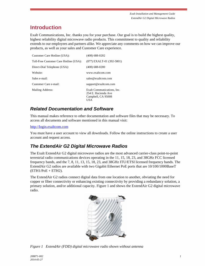
The ExtendAir G2 radios connect digital data from one location to another, obviating the need for copper or fiber connectivity or enhancing existing connectivity by providing a redundancy solution, a primary solution, and/or additional capacity. Figure 1 and shows the ExtendAir G2 digital microwave radio.
Figure 1 ExtendAir (FDD) digital microwave radio shown without antenna
Customer Care Hotline (USA): (408) 688-0202
Toll-Free Customer Care Hotline (USA): (877) EXALT-01 (392-5801)
Direct-Dial Telephone (USA): (408) 688-0200
Website: www.exaltcom.com
Sales e-mail: [email protected]
Customer Care e-mail: [email protected]
Mailing Address: Exalt Communications, Inc.254 E. Hacienda AveCampbell, CA 95008USA
Exalt Installation and Management Guide
ExtendAir G2 Digital Microwave Radios
2 208871-002
2014-05-27
The ExtendAir G2 model number scheme uses the first two digits to define the general frequency band (in GHz) and the last three digits to define the connector and base configuration.
The following models of radios are covered in this manual:
• rc11020, rc15020, rc18020, rc23020, and rc38020 FCC models for the 11, 15, 18, 23, and 38GHz FCC part 101 licensed bands, respectively
• rc07020, rc08020, rc11020, rc13020, rc15020, rc18020, rc23020, and rc38020 ITU/ETSI models for the 7, 8, 11, 13, 15, 18, 23, and 38GHz ITU and ETSI licensed bands, respectively
• ExtendAir G2 models have one 10/100/1000BaseT PoE port and one additional 10/100/1000BaseT port
– configured with 25Mbps of full-duplex Ethernet capacity
– with license key upgrade for 50, 100, 200, 300, and 370 full-duplex capacity
– with license key upgrade for FIPS-197 compliant 128-bit or 256-bit AES encryption
The ExtendAir G2 models require a clear line-of-sight and proper path clearance to achieve a high-performance, reliable connection. Perform professional path engineering and site planning before installing this equipment.
The primary focus of this document is the installation and maintenance of the digital microwave radio, and assumes that path engineering and site planning were already performed.
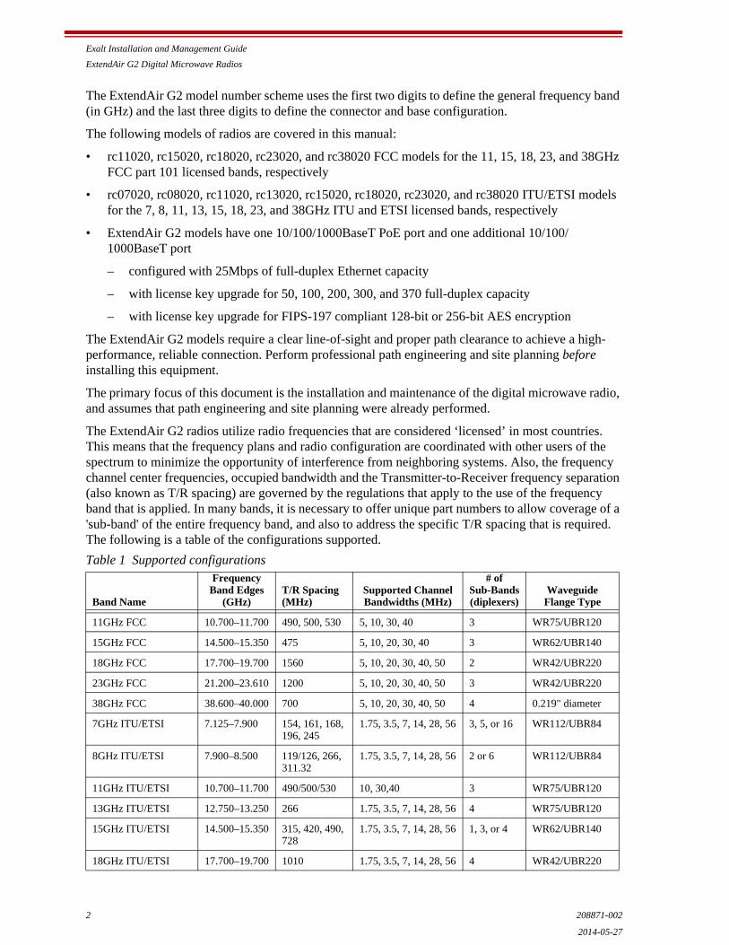
The ExtendAir G2 radios utilize radio frequencies that are considered ‘licensed’ in most countries. This means that the frequency plans and radio configuration are coordinated with other users of the spectrum to minimize the opportunity of interference from neighboring systems. Also, the frequency channel center frequencies, occupied bandwidth and the Transmitter-to-Receiver frequency separation (also known as T/R spacing) are governed by the regulations that apply to the use of the frequency band that is applied. In many bands, it is necessary to offer unique part numbers to allow coverage of a 'sub-band' of the entire frequency band, and also to address the specific T/R spacing that is required. The following is a table of the configurations supported.
Table 1 Supported configurations
Band Name
FrequencyBand Edges
(GHz)T/R Spacing(MHz)
Supported Channel Bandwidths (MHz)
# ofSub-Bands(diplexers)
WaveguideFlange Type
11GHz FCC 10.700–11.700 490, 500, 530 5, 10, 30, 40 3 WR75/UBR120
15GHz FCC 14.500–15.350 475 5, 10, 20, 30, 40 3 WR62/UBR140
18GHz FCC 17.700–19.700 1560 5, 10, 20, 30, 40, 50 2 WR42/UBR220
23GHz FCC 21.200–23.610 1200 5, 10, 20, 30, 40, 50 3 WR42/UBR220
38GHz FCC 38.600–40.000 700 5, 10, 20, 30, 40, 50 4 0.219" diameter
7GHz ITU/ETSI 7.125–7.900 154, 161, 168, 196, 245
1.75, 3.5, 7, 14, 28, 56 3, 5, or 16 WR112/UBR84
8GHz ITU/ETSI 7.900–8.500 119/126, 266, 311.32
1.75, 3.5, 7, 14, 28, 56 2 or 6 WR112/UBR84
11GHz ITU/ETSI 10.700–11.700 490/500/530 10, 30,40 3 WR75/UBR120
13GHz ITU/ETSI 12.750–13.250 266 1.75, 3.5, 7, 14, 28, 56 4 WR75/UBR120
15GHz ITU/ETSI 14.500–15.350 315, 420, 490, 728
1.75, 3.5, 7, 14, 28, 56 1, 3, or 4 WR62/UBR140
18GHz ITU/ETSI 17.700–19.700 1010 1.75, 3.5, 7, 14, 28, 56 4 WR42/UBR220

Exalt Installation and Management Guide
ExtendAir G2 Digital Microwave Radios
208871-002 32014-05-27
In most cases, there are regulations, or device-based conditions that limit the use of the device, such as minimum or maximum gain antenna, antenna polarization, and maximum output power, as well as, in some cases, application limits, limited geography of use, and other unique regulations. The link design engineer and/or professional installer must determine these limitations and engineer/install the system within the confines of all local regulations. Also, it is required to examine any regulations that may apply to peripheral equipment, installation and cabling of the system that may be regulated for human safety, electrical code, air-traffic control, and other safety-related categories. In some cases, a need for link registration, coordination, and fees that may apply to the system usage. Please consult your local regulatory organization(s) to determine usage requirements.
In almost all cases, the product itself must be authorized for use in your country. Either Exalt or Exalt’s agent must have applied for certification or authorization to allow the sale and deployment of the system within the country. It is also possible that only certain versions or configurations of the device are allowed within a particular country. Please contact Exalt or your authorized Exalt representative for information pertaining to your country.
Basic Features
The ExtendAir G2 Digital Microwave Radios are intended for all-outdoor mounting and come with an indoor-mounted power injector. In some cases, the radio can be mounted indoors or in an enclosure.
For most implementations, the entire unit is typically mounted on a tower or rooftop mast structure, with Ethernet/Power and other optional interface cables running from the unit location, through a structure penetration, and to the power injector and connected communications equipment.
When mated to the proper antenna, the radio is mounted directly to the antenna, eliminate RF cabling and associated losses. Alternatively, the unit can be mounted very close to a standard waveguide feed antenna, and a flexible waveguide is connected between the antenna and the radio. The distance between the radio and the antenna should always be minimized to, in turn, minimize waveguide length and associated losses.
23GHz ITU/ETSI 21.200–23.610 1008, 1200, 1232
1.75, 3.5, 7, 14, 28, 56 2, 3, or 4 WR42/UBR220
38GHz ITU/ETSI 37.040–40.00 1260 1.75, 3.5, 7, 14, 28, 56 2 0.219" diameter
Note: It is the professional installer’s responsibility to ensure that the radio system is implemented in a legal fashion. Exalt is not liable for any unsafe or illegal installations.
Table 1 Supported configurations (Continued)
Band Name
FrequencyBand Edges
(GHz)T/R Spacing(MHz)
Supported Channel Bandwidths (MHz)
# ofSub-Bands(diplexers)
WaveguideFlange Type

Exalt Installation and Management Guide
ExtendAir G2 Digital Microwave Radios
4 208871-002
2014-05-27
Figure 2 Cabling and surge suppression
The ExtendAir G2 radios provide connections for up to two Gigabit Ethernet data communication interfaces, and are powered by a combined Power/Ethernet cable, and associated power injector. The power injector provides 48VDC to the unit. The power injector and/or external power supply are sold separately.
The ExtendAir G2 radios provide the following primary features and benefits:
• Low-latency optimization for voice and data connections
• Very high throughput and flexible interface configurations with voice+data combinations
• Encryption for extreme wireless security
• Easy-to-use management and configuration
• Flexible utilized channel bandwidth and modulation selections, with field-interchangeable diplexers for low-cost sparing and easy capacity and frequency coordination
• Flexible center frequency tuning for interference avoidance and frequency coordination
• Flexible capacity to meet current connection requirements and future growth needs
• Carrier-class reliability and performance
• Connector covers (for weatherproofing unused connectors)
Exalt Installation and Management Guide
ExtendAir G2 Digital Microwave Radios
208871-002 52014-05-27
Preinstallation TasksThis section describes the steps necessary to prepare a site for the installation of the Exalt Digital Microwave Radio.
Link Engineering and Site Planning
Design all terrestrial wireless links prior to purchase and installation. Generally, professional wireless engineering personnel are engaged to determine the viability and requirements for a well-engineered link to meet the users’ needs for performance and reliability.
The link engineering will determine the following attributes:
• Antenna type/gain at each end of the link
• Antenna mounting height/location for proper path clearance
• Antenna polarization orientation
• Waveguide (if any), cabling, lengths, connectors, routes, and mounting
• Antenna system grounding
• Lightning arrestor type(s), location(s), and grounding
• Radio mounting location and mechanisms
• Radio grounding
• Radio transmitter output power setting
• Anticipated received signal level (RSL) at each end
• Anticipated fade margin and availability performance at each end
• Radio settings for modulation and occupied bandwidth
• Anticipated throughput performance
With respect to radio path and site planning, these radios are generally identical to other microwave terrestrial wireless systems. Engineering of these systems requires specific knowledge about the radios, including:
• RF specifications (transmitter output power, receiver threshold, occupied channel bandwidth, and carrier-to-interference tolerance)
• Regulatory limitations on transmitter output power setting and antenna type/gain
• Noise/interference profile for the intended location (where applicable)
Familiarization with the ExtendAir G2 Radios
The ExtendAir G2 radios utilize frequency division duplex (FDD) radio transmission. This means that the signal transmits on one center frequency in one direction while simultaneously transmitting on a different center frequency in the opposite direction. This provides full-duplex configuration with equal capacity in both directions and minimal latency.
The radios are configured in High (Hi) and Low (Lo) pairs, with alternate frequency settings for Transmit and Receive on the opposite ends of the link. This configuration is determined by the installed internal diplexer, which determines the specific tunable frequencies of the radio (relative to the occupied bandwidth setting) and the Hi/Lo orientation. These diplexers can be configured in the field to ease sparing and re-configuration.

Exalt Installation and Management Guide
ExtendAir G2 Digital Microwave Radios
6 208871-002
2014-05-27
Exalt recommends using the Exalt GUI for radio configuration. This interface requires a computer with an Ethernet port and web browser software, such as Microsoft Internet Explorer 5.0 or above. See Configuration and Management for details on how to connect to and use the browser-based GUI interface.
Shipping Box Contents
The terminals are shipped as individual endpoints. As mentioned, it takes two terminals–one Hi and one Lo–to make a complete link. An outer box has labeling that indicates the contents of the box, with the part number and serial number details for the radio terminal. The terminal box contains the following items:
• Radio terminal
• Registration card
• Quick-start guide
Power solutions are sold separately. Power for the ExtendAir G2 models comply with the 802.3at Power-over-Ethernet (PoE) standard. Any 802.3at PoE device is compliant with these models.
The radio is typically mounted to the proper direct-mount antenna, therefore no mounting hardware is required. For remote-mount solutions where the radio will use a flexible waveguide for connection to the antenna, a separate pole-mounting kit is sold separately.
Inspect the outer packaging and the contents of the boxes upon receipt. If you suspect any shipping damage or issues with the contents, contact Exalt Customer Care (see Introduction).
Outdoor-rated and shielded CAT5e cable, such as Beldon 1300A, with RJ-45 or RJ-48C connectors is recommended for the Ethernet connections. For Ethernet connections, a maximum length of 100 meters applies to the total length of the cabling between the radio terminal and the first network-aware connection (such as a switch or router).
Initial Configuration and Back-to-Back Bench Test
Every Exalt digital microwave radio goes through extensive quality testing and performance evaluation over the full operating temperature range prior to shipment. However, before installation, it is strongly advised to perform several tests and tasks that are much more difficult to perform once the radio link endpoints are distant from one another. A back-to-back bench test and pre-configuration will provide confidence that the radio link is operational and properly configured prior to installation, so that if troubleshooting is necessary, the radio hardware and configuration settings are eliminated from the troubleshooting process. Verify the following in the back-to-back testing:
• Confirm that the radio system is generally operational
– Radios power-up with planned power and wiring solutions
– Radio firmware version matches on each terminal (and is ideally the latest version)
– Upgrade license key entry successful
– RF link connects in both directions
– Traffic passes across the link
Note: Register your system as soon as possible. A 2-year Warranty period applies to products registered within 90 days of purchase. The Warranty period is reduced to 1-year for unregistered products and products registered after the first 90 days. See Exalt Limited Hardware Warranty Software License and RMA Procedures Agreement.
Exalt Installation and Management Guide
ExtendAir G2 Digital Microwave Radios
208871-002 72014-05-27
• Configure connected equipment and cabling
– Test Ethernet (CAT5e) cabling, any auxiliary connector cabling, and configure all interfaces
– Configure IP settings for configuration and management
– Configure passwords and security modes
– Become familiar with the configuration and management interfaces through the Exalt GUI interface
– Configure radio parameters
– Set transmitter output power to engineered or allowed level (see RF Output Power Setting)
– Set operating center frequency
– Set occupied channel bandwidth and modulation
• Make detailed radio performance measurements
– Measure transmitter output power
– Measure receiver threshold performance
– Confirm unfaded error-free performance
Some of these tasks may not be possible or practical within a bench test environment due to the nature of the remote connectivity of peripheral equipment. However, it is good practice to perform as much as possible in this environment to minimize field/installation time and troubleshooting efforts.
Detailed performance measurements are usually not required for pre-installation, but can be easily performed at this stage and may be helpful for later troubleshooting efforts or for internal records. During troubleshooting, there may often be a point at which a back-to-back bench test should be performed to verify many or all of the above items, and in the case of a suspected faulty device, to help confirm the fault and determine which end of the system is at fault and in need of repair or replacement.
RF Output Power Setting
The maximum RF output power is bounded by one of the following criteria:
• Maximum RF output power setting capability of the radio device
• Maximum RF output power allowed/authorized by the local government regulations and for this specific device
• Maximum effective isotropic radiated power (EIRP) of the transmission system allowed/authorized by the local government regulations and for this specific device
• Desired RSL to not exceed the maximum RSL allowed by the device
• Desired RSL to minimize/eliminate interference into neighboring systems
Note: See Back-to-back Bench Testing for detailed instructions.
Note: In many cases the radio must be pre-configured for legal maximum output power before connecting to the antenna and transmission system. Instructions for adjusting the output power can also be found in Power.

Exalt Installation and Management Guide
ExtendAir G2 Digital Microwave Radios
8 208871-002
2014-05-27
Critical Configuration Considerations
The ExtendAir G2 radios are very dynamic, allowing the installer to optimize and control the performance of the radio system for the intended application. The following parameters must be carefully determined during the link engineering phase:
• Bandwidth
• Mode (modulation)
The setting of the above parameters combined with the license key determines the Ethernet throughput.
Use a professional link planning tool to determine optimum settings for the above parameters to meet the needs of your application.
Note the following generalizations regarding these factors:
• The higher the bandwidth, the higher the capacity
• The higher the mode, the higher the capacity
Radios arrive from manufacture in default configuration configured as shown in Table 2.
Table 2 Factory default settings
Parameter ExtendAir G2
Frequency Lowest frequency pair supported by software-configured diplexer
Transmit Power 0 dBm or lowest power supported by frequency band
Bandwidth Minimum value supported by model (typically 5MHz for FCC models, 3.5MHz for ITU/ETSI models), depending upon frequency band
Mode (modulation) Minimum modulation supported by model (typically QPSK)
Link Security Key 000000000000
Administration Password password
User Password password
IP Address 10.0.0.1 (for Tx Low); 10.0.0.2 (for Tx High)
IP Mask 255.0.0.0
IP Gateway 0.0.0.0
Ethernet Interfaces Alarm Enabled, Auto-negotiate
Note: In many cases, the system design will not be identical to the factory default configuration, and in some cases, these differences prohibit the installation of the radio. If at all possible, obtain a computer and configure the radio terminals using the browser-based GUI. See Exalt Graphical User Interface (GUI).

Exalt Installation and Management Guide
ExtendAir G2 Digital Microwave Radios
208871-002 92014-05-27
Radio Reset
Use the reset function if the IP address and/or passwords are lost. Use the steps particular to your radio model to perform a critical parameter reset.
The following configurations are reset on the radio when performing a reset:
• IP address = 10.0.0.1
• IP mask = 255.0.0.0
• IP gateway = 0.0.0.0
• Administration password = password
• User password = password
• VLAN = disabled
Performing a Reset
To perform a radio reset, you must have a mechanism to connect the radio’s RSL/BNC port between the center pin and the shield to provide a “short” between the two conductors. Common methods for this are:
• Using the BNC termination provided in the radio accessory kit.
• Using a standard voltmeter BNC cable, attach a jumper clip to the voltmeter end to short the two conductors.
• Using a BNC male connector assembly, connect or solder a wire or jumper to short the center pin and outer shield.
Once the RSL/BNC port shorting mechanism solution is identified, follow this procedure:
1 Remove the power source, preferably at the PoE DC input.
2 Remove the RSL/BNC port cover on the radio.
3 Install the RSL/BNC port shorting mechanism chosen above.
4 Apply power.
5 Wait until the internal beeper sounds (approximately 1 minute). You can verify the reset by pinging the 10.0.0.1 default IP address.
6 Remove the RSL/BNC port shorting mechanism.
7 Replace the RSL/BNC port cover.
Virtual Local Area Network (VLAN)
VLAN segments information in a single connection and creates multiple separate connections to secure information of one type or for one set of users from other information types or for other sets of users. Exalt’s VLAN communications implementation adheres to the IEEE standard 802.1q.
In most cases, an Exalt radio acting as a Layer 2 bridge between two locations is only required to pass traffic with VLAN tagging. Without additional configuration, all Exalt radios support frame sizes in excess of 1900 bytes, which currently supports all defined VLAN packet sizes.
Exalt Installation and Management Guide
ExtendAir G2 Digital Microwave Radios
10 208871-002
2014-05-27
Some situations require Exalt radios to act upon VLAN traffic and perform any or all of the following functions:
• Connect specific traffic, using VLAN tagging, to a specific port on the radio, such as management traffic to the ETH1/PoE port.
• Allow only traffic with specifically assigned VLANs to pass across the link, blocking all other VLANs or any non-VLAN traffic.
• Allow management access only through a VLAN connection, leaving the main traffic transparent.
• Allow management access without a VLAN connection, but flowing only specific VLAN traffic across the link.
Simple Network Management Protocol (SNMP)
The Exalt radios primarily use a browser-based graphical user interface (GUI) for radio configuration and management, as described in Exalt Graphical User Interface (GUI). In addition, a command line interface (CLI) is provided for serial and/or Telnet access, as described in Command Line Interface (CLI). SNMP is often used for management of larger networks as described here. Use SNMP to manage networked devices and execute the following functions:
• GET: Obtain information from the device, such as a configuration setting or parameter.
• SET: Change a configuration setting on the device.
• TRAP: The device proactively informs the management station of a change of state, usually used for critical alarms or warnings.
One feature of the SNMP implementation is that system configuration changes do not take effect using the SET command. Instead, groups of configuration settings can be preconfigured for global change, and a single ‘Save’ (Commit) command implements all changes.
When some parameters are changed, a link may drop and/or management control lost. MIB files allow many parameters to be set at once, allowing only a temporarily dropped link or management control issue. The opposite end radio can be quickly reconfigured, with little downtime for the link and management control. The save (Commit) command is similar to the Update button.
Dropped links or management control issues do not occur with every parameter change. Many configuration changes do not impact traffic or management access.
Exalt radios utilize SNMPv3, a high security version of SNMP, to ensure secure access to and storing of management data. The SNMPv3 security string matches the admin and user passwords. Passwords must be eight characters or longer. Some models also have “legacy” SNMP support for SNMPv1 and SNMPv2.
Note: If an application only requires the transparent passing of VLAN traffic, disable the VLAN function.
Note: MIB files are listed on the File Transfer Page.

208871-0022014-05-27
System Installation and Initiation ProcessThe tasks required for radio installation and initiation are outlined in the following figure.
Figure 3 Radio installation tasks
Path & Site Analysis
Link Design
Build Antenna Structures &
Egress
Mount Antennas &
Transmission Line
Install & Test Network &
Power Wiring
Read This Manual
Completely
Pre-configure Radios
Perform Back-to-Back
Test
Mount Radios
Connect Transmission
Line
Connect Power
Align Antennas to Planned RSL
Verify LEDs for Good Link
Test Network Connectivity
Connect & Test Primary
Services
Test Network Management
System
Both Transmission System & Radio
Preparation Tasks Must Be Complete
Transmission System Tasks Radio Preparation Tasks

Exalt Installation and Management Guide
ExtendAir G2 Digital Microwave Radios
208871-002 122014-05-27
Record Keeping
After installation, record the following items for ongoing maintenance and future troubleshooting. Keep a record for each end of the radio link and store a copy of these records at the radio location, at the opposite end radio location, and a central record storage location.
• GPS coordinates for antenna locations at each site
• Antenna heights above ground level (AGL), as mounted
• Antenna model numbers, serial numbers, and specifications
• Antenna polarization as mounted
• Length/type of primary transmission lines at each site
• Model number and serial number of lightning arrestors
• Transmitter output power setting as installed at each site
• RSL as measured after antenna alignment at each site
• Designed RSL per original design at each site
• RSL reading with far-end power off (from each end)
• Spectrum analyzer plot with far end off at each site
• Radio’s network management IP address at each site
• Radio’s network management gateway address at each site
• Radio’s operating frequency, bandwidth setting, and mode of operation
• Optionally purchased extended warranty and/or emergency service contract details
In addition, certain information may be desired for central record-keeping only:
• Link security codes and log in passwords (stored in a secure place)
• Photographs of complete installation
• End-user sign-off/acceptance documentation (if any)
• Photo of product identification label (part number, serial number, MAC address information)
• Electronic copy of radio’s configuration file
• Electronic copy of radio’s installed software
Exalt Installation and Management Guide
ExtendAir G2 Digital Microwave Radios
13 208871-002
2014-05-27
InstallationThis section presents all tasks required to install the Exalt Digital Microwave Radio.
Mechanical Configuration and Mounting
The ExtendAir G2 radios are environmentally sealed units intended for deployment outdoors. The device must be deployed within an ambient temperature range as specified, and with non-restrictive airflow around the chassis.
Provide proper clearance for all cables and connectors attached to the device.
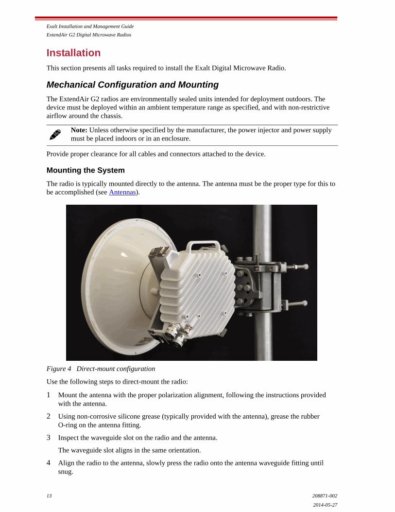
Mounting the System
The radio is typically mounted directly to the antenna. The antenna must be the proper type for this to be accomplished (see Antennas).
Figure 4 Direct-mount configuration
Use the following steps to direct-mount the radio:
1 Mount the antenna with the proper polarization alignment, following the instructions provided with the antenna.
2 Using non-corrosive silicone grease (typically provided with the antenna), grease the rubber O-ring on the antenna fitting.
3 Inspect the waveguide slot on the radio and the antenna.
The waveguide slot aligns in the same orientation.
4 Align the radio to the antenna, slowly press the radio onto the antenna waveguide fitting until snug.
Note: Unless otherwise specified by the manufacturer, the power injector and power supply must be placed indoors or in an enclosure.
Exalt Installation and Management Guide
ExtendAir G2 Digital Microwave Radios
208871-002 142014-05-27
5 Secure the mounting clips on the four corners of the radio chassis to the mating clips on the antenna, one at a time.
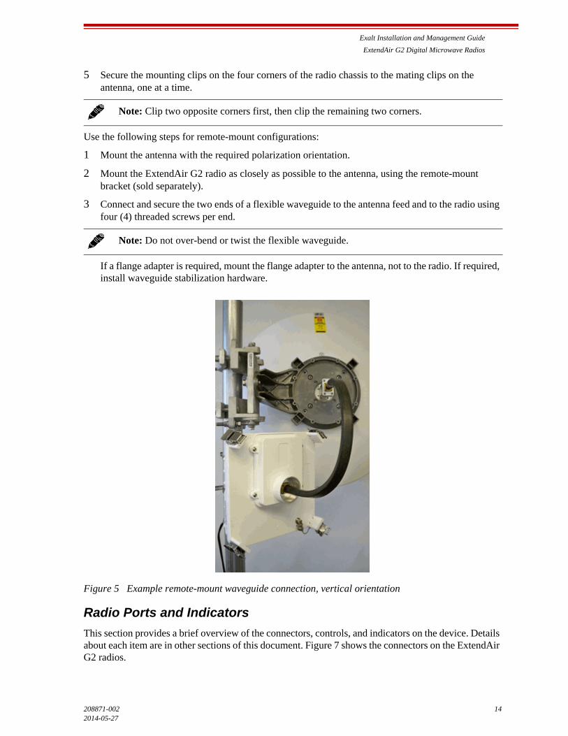
Use the following steps for remote-mount configurations:
1 Mount the antenna with the required polarization orientation.
2 Mount the ExtendAir G2 radio as closely as possible to the antenna, using the remote-mount bracket (sold separately).
3 Connect and secure the two ends of a flexible waveguide to the antenna feed and to the radio using four (4) threaded screws per end.
If a flange adapter is required, mount the flange adapter to the antenna, not to the radio. If required, install waveguide stabilization hardware.
Figure 5 Example remote-mount waveguide connection, vertical orientation
Radio Ports and Indicators
This section provides a brief overview of the connectors, controls, and indicators on the device. Details about each item are in other sections of this document. Figure 7 shows the connectors on the ExtendAir G2 radios.
Note: Clip two opposite corners first, then clip the remaining two corners.
Note: Do not over-bend or twist the flexible waveguide.
Exalt Installation and Management Guide
ExtendAir G2 Digital Microwave Radios
15 208871-002
2014-05-27
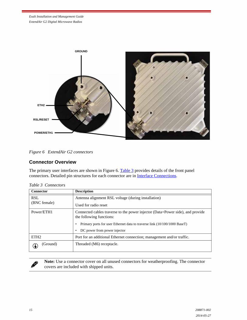
Figure 6 ExtendAir G2 connectors
Connector Overview
The primary user interfaces are shown in Figure 6. Table 3 provides details of the front panel connectors. Detailed pin structures for each connector are in Interface Connections.
Table 3 ConnectorsConnector Description
RSL(BNC female)
Antenna alignment RSL voltage (during installation)
Used for radio reset
Power/ETH1 Connected cables traverse to the power injector (Data+Power side), and provide the following functions:
• Primary ports for user Ethernet data to traverse link (10/100/1000 BaseT)
• DC power from power injector
ETH2 Port for an additional Ethernet connection; management and/or traffic.
(Ground) Threaded (M6) receptacle.
Note: Use a connector cover on all unused connectors for weatherproofing. The connector covers are included with shipped units.
GROUND
ETH2
RSL/RESET
POWER/ETH1
Exalt Installation and Management Guide
ExtendAir G2 Digital Microwave Radios
208871-002 162014-05-27
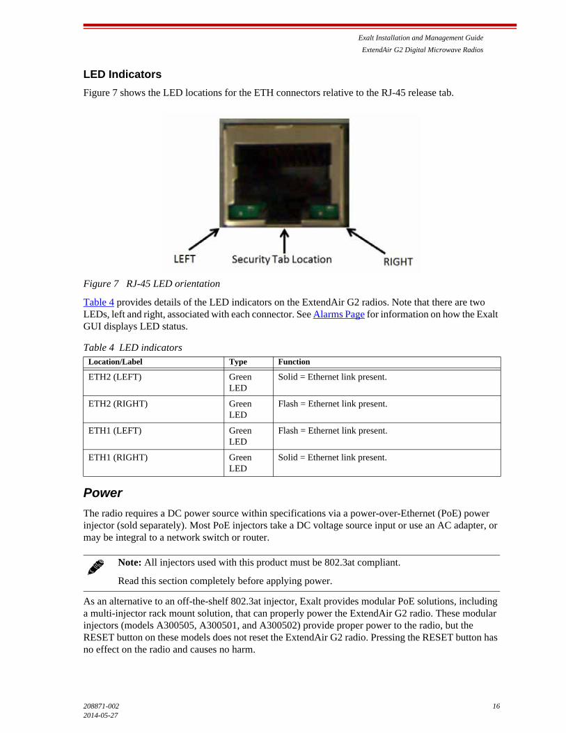
LED Indicators
Figure 7 shows the LED locations for the ETH connectors relative to the RJ-45 release tab.
Figure 7 RJ-45 LED orientation
Table 4 provides details of the LED indicators on the ExtendAir G2 radios. Note that there are two LEDs, left and right, associated with each connector. See Alarms Page for information on how the Exalt GUI displays LED status.
Power
The radio requires a DC power source within specifications via a power-over-Ethernet (PoE) power injector (sold separately). Most PoE injectors take a DC voltage source input or use an AC adapter, or may be integral to a network switch or router.
As an alternative to an off-the-shelf 802.3at injector, Exalt provides modular PoE solutions, including a multi-injector rack mount solution, that can properly power the ExtendAir G2 radio. These modular injectors (models A300505, A300501, and A300502) provide proper power to the radio, but the RESET button on these models does not reset the ExtendAir G2 radio. Pressing the RESET button has no effect on the radio and causes no harm.
Table 4 LED indicatorsLocation/Label Type Function
ETH2 (LEFT) Green LED
Solid = Ethernet link present.
ETH2 (RIGHT) Green LED
Flash = Ethernet link present.
ETH1 (LEFT) Green LED
Flash = Ethernet link present.
ETH1 (RIGHT) Green LED
Solid = Ethernet link present.
Note: All injectors used with this product must be 802.3at compliant.
Read this section completely before applying power.
Exalt Installation and Management Guide
ExtendAir G2 Digital Microwave Radios
17 208871-002
2014-05-27
Terminating the RF Connection
Before applying power, the device’s RF connection must be properly terminated into a 50-Ohm load. If this is not performed, the radio may be damaged by simply applying power. Also, there are human safety factors to consider regarding potentially harmful RF radiation.
There are a few simple means to accommodate proper termination:
• Connect a waveguide/coaxial adapter and 50-Ohm coaxial termination device to the RF port of the radio. The termination must be rated to 1W (or more).
• Connect the complete transmission system. That is, the waveguide and the antenna. The connected antenna provides a proper termination for the RF output.
Applying Power
Do not plug the injector into the main power source first. First, verify that the RF connector is properly terminated (see Power), and then plug in the radio-side connector from the injector to the radio. If the power source can be turned off using a switch, disable the power, plug the power supply side of the injector into the power source, and then enable power to the circuit. If the power source cannot be turned off, plug in to the power input side of the injector to apply power.
Exalt strongly recommends that the power supplies be fused or on a separate breaker to ensure against over-voltage and/or over-current situations and to provide some form of protection to the radio electronics and other devices connected to the same supply. In addition, if the power source is subject to significant spikes or variation, power conditioning is a worthwhile investment, as the quality of the power source may have a direct impact on the device operation, performance and/or reliability. An Uninterruptible Power Source (UPS) or other form of battery-backed system protects against brown-out and black-out conditions, and condition the power presented to the injector.
Evaluate the opportunity for lightning or other similar surges to be present on the powering system, including the ability for surges to couple to the power wiring system. If an evaluation indicates that there is a potential likelihood for these conditions to occur, additional surge protection is recommended for the input power wiring, especially to protect the radio electronics between the injector and the radio.
The above statement is similarly true for every wired connection to the device. While the configuration for surge suppression or line conditioning is of a different type for each kind of signal interface, the opportunity for damage to the device, loss of communications and property is significant. In some cases, there can also be a risk to human life by not protecting against lightning entering a building through wiring or improper grounding. If you do not have experience in this type of installation practice, consult a qualified electrician and/or telecoms professional during the installation and wiring of the equipment.
CAT5e or CAT6 Lightning/Surge Protection
To provide for human safety and for the safety of connected network equipment, it is highly recommended to place a weatherproof lightning suppression device at the egress point where the CAT5e/CAT6 cable(s) enter the building, shelter, or cabinet.
To protect the radio equipment, install a weatherproof lightning suppression device near the radio for all connected CAT5e/CAT6 cables.
For the Power/Ethernet cable, specific voltage requirements must be met. The following devices are the only devices currently recommended:
Do not apply power using a live RJ45 connector. Connect all RJ45 connectors first, and then apply power.
Exalt Installation and Management Guide
ExtendAir G2 Digital Microwave Radios
208871-002 182014-05-27
• Polyphaser IXG-05
• Transtector ALPU 1101-959
• Transtector ALPU-1000BT-R
• Citel C2MJ8-POE-A/SE
• Transtector 1101-1030
• Transtector 1101-1080
Generally, use a short CAT5e/CAT6 cable for the short connection between the radio and the first arrestor. Use bulk outdoor-rated CAT5e/CAT6 cable for the longer run between arrestors, and indoor- or outdoor-rated cable with a standard RJ45 termination for the connection from the egress arrestor and power injector. The cabling between the radio, through all arrestors, and to the power injector must follow a straight-wired convention, maintaining standard Ethernet pairing.
Diplexer (Channel Plan) Configuration
The ExtendAir G2 radio has a unique feature that allows field reconfiguration of the channel plan and/or the Hi/Lo Tx/Rx orientation. This allows a single spare unit to spare any configuration of the same frequency-band radio, as well as added flexibility for re-licensing if a link gets moved to a new location.
The transmitter (Tx) and receiver (Rx) frequency tuning range is determined by two things:
1 The model of the radio, and thus the frequency band and T/R spacing that is supported, and
2 The type and orientation of the diplexer filter installed in the radio, and thus the center frequencies for the Tx and Rx that can be set.
Four labels are provided on the diplexer to aid in the determination of the current configuration, as shown in Figure 8.
Note: Use only outdoor-rated UV-resistant CAT5e/CAT6 cable. The cable that directly connects to the radio must have an outer diameter between 0.25"/6.35 mm and 0.31"/7.87mm. Belden 1300A is recommended. Securely hand-tighten all connectors on the ODU to ensure a weatherproof seal.
CAUTION! Removal of the diplexer cover requires special care. The instructions in this section must be followed precisely to maintain performance and weatherproof operation. The Exalt Limited Hardware Warranty Software License and RMA Procedures Agreement may be void if damage to the radio occurs as a result of improper installation.

Exalt Installation and Management Guide
ExtendAir G2 Digital Microwave Radios
19 208871-002
2014-05-27
Figure 8 Diplexer configuration labels
• The Port label indicates the frequency range of the corresponding port (on the underside of the diplexer). One side is Tx and the other is Rx, depending on how it mounts to the radio.
• The ID label shows the name of the diplexer by band and Tx orientation. For example “15 B2-Lo” indicates 15GHz, Band 2, Low Tx. The T/R spacing may also be shown. This label also displays the ID number to select on the System Configuration Page.
To change diplexer configuration:
1 On the antenna-mounting side of the radio chassis, use a 5mm Hex wrench to remove the four (4) chassis cover screws shown below.
2 Use a forceful back-and-forth motion to pivot the two halves of the chassis against each other until they separate.
Note: Since the diplexer cannot be seen without removing the front cover, it is critical that the external labeling is changed if the diplexer is changed. For convenience, labels are provided with any spare diplexers purchased.
Exalt Installation and Management Guide
ExtendAir G2 Digital Microwave Radios
208871-002 202014-05-27
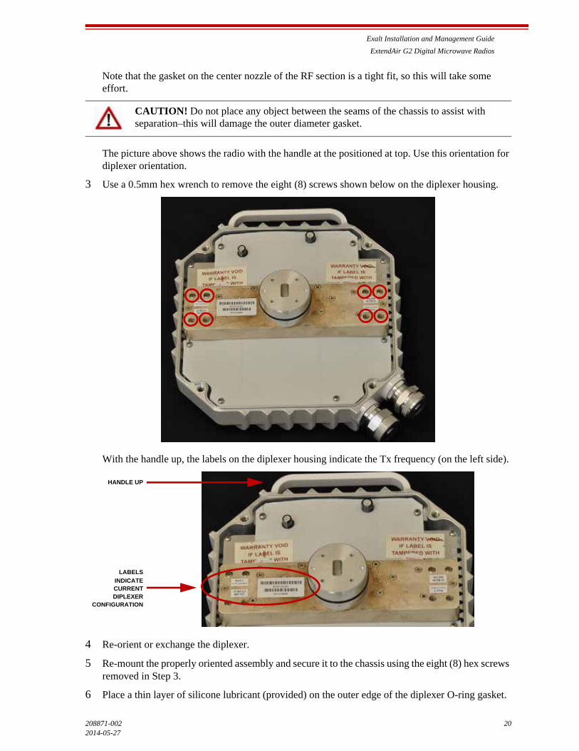
Note that the gasket on the center nozzle of the RF section is a tight fit, so this will take some effort.
The picture above shows the radio with the handle at the positioned at top. Use this orientation for diplexer orientation.
3 Use a 0.5mm hex wrench to remove the eight (8) screws shown below on the diplexer housing.
With the handle up, the labels on the diplexer housing indicate the Tx frequency (on the left side).
4 Re-orient or exchange the diplexer.
5 Re-mount the properly oriented assembly and secure it to the chassis using the eight (8) hex screws removed in Step 3.
6 Place a thin layer of silicone lubricant (provided) on the outer edge of the diplexer O-ring gasket.
CAUTION! Do not place any object between the seams of the chassis to assist with separation–this will damage the outer diameter gasket.
HANDLE UP
DIPLEXERCONFIGURATION
CURRENTINDICATE
LABELS

Exalt Installation and Management Guide
ExtendAir G2 Digital Microwave Radios
21 208871-002
2014-05-27
7 Replace the cover and secure the four (4) Hex screws on the radio chassis,
8 Place new labeling on the radio chassis, as necessary.
Antenna/Transmission System
This section provides guidance to mounting and connecting the RF transmission system, which consists of the antenna, RF cabling, and RF lightning arrestors. Consult the manufacturer's instructions for proper mounting, grounding, and wiring of these devices, and for definitive direction. These manufacturer's instructions supersede any information in this section. See Antennas for a list of supported antennas.
Initial Antenna Mounting
The antenna must be an exact model recommended by the path and site planning engineer(s). Mount the antenna at the proper height, mast/mounting location and polarization orientation as determined by the path and site planning engineer(s). The model type, location, and orientation of the antenna is critical with respect to achieving proper path clearance, as well as to mitigate external or self- interference from nearby or collocated systems operating in or near the same frequency band.
The antenna structure must be secure and safe with respect to the mounting of the antenna, transmission system weight, radio housing, and the combined weight of any personnel that may climb or attach to the structure.
The combined weight of items and forces on the structure must be carefully considered in the design and construction of the structure. This must include the weight bearing on the structure in the highest wind conditions possible in the region, and with respect to all objects affixed to the structure.
If additional objects are affixed to the structure in the future, it may be important to evaluate both the mechanical impact of these planned additions (with respect to wind and weight loading), as well as the potential impact to RF interference and frequency coordination (if additional radio equipment is anticipated). This is especially important if future equipment is likely to operate within the same frequency band.
Once the antenna is mounted, cabled, and aligned, your goal is to never require modification. This prior planning is important in the path and site planning stages and in construction of the antenna structure.
Follow the antenna manufacturer’s instructions for mechanical mounting of the antenna. Ensure that there is enough room around the antenna for alignment activities (moving the antenna in vertical and horizontal arcs), and for the RF transmission line to connect to the antenna connector unobstructed and within the specified bend radius requirements of the transmission line.
CAUTION! Do not pinch the rubber O-ring gasket.
Note: The chassis must have the right labels. The ID number of the diplexer is used to program the radio GUI on the System Configuration Page.
Warning! Mount the antenna in a restricted area and in a manner preventing long-term human exposure to the transmitted RF energy. Consult your government guidelines for proper signage and/or safe distance considerations for radio equipment.
Exalt Installation and Management Guide
ExtendAir G2 Digital Microwave Radios
208871-002 222014-05-27
At this point, the antenna mounts should be fully secure to the structure, the feed of the antenna securely mounted to the antenna (if the feed is a separate assembly), and the azimuth and elevation adjustments not completely tightened in preparation of the antenna alignment activity. It is a good practice to connect the transmission line to the antenna connector as early in the process as possible, to reduce the opportunity for debris or moisture to enter either the antenna connector or the transmission line connector. Use a connector cover or other temporary measures to ensure that the connector is kept clear. Take extra care if the antenna is installed during inclement weather to ensure that no moisture gets inside the antenna connector at any time.
Now the antenna can be aimed in the general direction required for the link. Use a compass, a reference bearing, binoculars or any other similar device to point the antenna in the direction (generally) of the far end radio, and then slightly tighten the azimuth and elevation adjustments so that the antenna maintains its general position and is safe to be left without additional securing. Refer to the Exalt white paper, Antenna Alignment, for more information on antenna alignment techniques.
Transmission Line from Antenna to Radio (Remote Mount)
It is recommended using a direct-mount antenna and mount the radio directly to the antenna. Using a ‘standard’ waveguide antenna is considered a ‘remote mount’ implementation. Use the remote-mount kit to mount the radio near the antenna feed. Generally, the orientation of the waveguide slot on the radio will be the same as the antenna feed (either vertical or horizontal).
If using an antenna that does not allow a direct-mount solution, use a short segment of flexible waveguide between the radio and antenna. Always minimize the length of the waveguide to reduce additional RF losses in the system, which may negatively impact performance.
The flexible waveguide may have a piece of mylar tape over the entrances of the guide. The antenna feed and radio may also have a similar piece of tape. This tape assures that no dust, dirt, or moisture enters the transmission system. It is recommended to remove the tape from the waveguide and/or antenna and allow it to remain on the antenna and radio. All pieces can be removed, but always ensure that no debris or moisture can enter the system. The radio can retain the mylar tape on the waveguide entry slot.
A proper waveguide flange provides a weatherproof seal to both the antenna and radio. The waveguide should have a rubber seal that encompasses the waveguide entry. When the flanges are connected and mechanics tightened, this forms the weatherproof seal.
In some cases, waveguide stabilization arms (supplied separately from the waveguide supplier) may be needed. If the waveguide is long and/or mounted in a way that allows the waveguide to move (for example, in windy conditions), it may introduce bit errors and/or RSL variation.
If the installation requires the radio be mounted more than three meters from the antenna, use a traditional rigid waveguide (not flexible) for all or most of the connection between the radio and antenna. A rigid waveguide exhibits lower losses, but requires more effort and cost for installation, and potentially requires pressurization equipment.
When selecting a waveguide, ensure that one side of the waveguide has the proper mating flange for the radio and the opposite side of the waveguide has the proper mating flange for the antenna. Also, that the waveguide size (for example, WR-75) is the same on both the radio and the antenna. If these do not match, a waveguide transition is required. Waveguide transitions either mount directly to the radio or to the antenna, and the flanges must properly mate. The other side of the waveguide transition must properly mate to the waveguide flange. Consult your waveguide and/or antenna supplier for details. Present the supplier with the mating flange information for the radio, which is in Table 1.

Exalt Installation and Management Guide
ExtendAir G2 Digital Microwave Radios
23 208871-002
2014-05-27
Antenna Alignment
Antennas must be installed at both ends of the planned link to commence precision alignment. Refer to the Exalt white paper, Antenna Alignment.
Antennas are typically aligned using the radio hardware for precise alignment. However, there are many very useful tools available to aid in this process, inclusive of devices specifically designed for the purpose of aligning antennas. Some examples are:
• XL Microwave Path Align-R
• Teletronics 17-402
Use of these devices may be extremely advantageous as compared to using the radio, because they employ many unique facilities to aid in this process. Using these tools also makes it possible to align the antennas before the radio equipment is delivered. However, many installers successfully use the radios as the means for antenna alignment.
There are two primary facilities when using the radio to align the antenna:
• RSL voltage test point using a volt meter (recommended)
A voltmeter with a BNC male connector can be directly connected to the RSL connector on the radio. The RSL test point DC voltage is inversely proportional and numerically calibrated to the received signal level. The voltage rises as the antennas are less in alignment, and falls as antennas are more in alignment. The voltage measurement corresponds to the received signal level in measurements of dBm (a negative number for RSL measurements). For example, an RSL of –60dBm yields an RSL voltage measurement of 0.60VDC; an RSL of –45dBm measures 0.45VDC.
• Audio alignment buzzer
Enable the audio alignment buzzer through the Exalt GUI. When enabled, the radio enclosure emits a sound. The pitch rises when higher (better) levels of RSL are achieved. Align the antennas until the highest pitch is accomplished. The tone is continuous when the two ends of the radio system are in communication. Otherwise, the buzzer beeps.
• Exalt GUI RSL reading indicates the current RSL in dBm.
Note: There is a slight delay in RSL readings in the GUI as the RSL levels change. In this case, fine alignment can be done in small adjustments allowing a small gap of time so that the impact of the adjustment on the GUI display catches up to real time.
Note: Only use the browser-based GUI for antenna alignment if there are no other means available. If this method is required, refer to Exalt Graphical User Interface (GUI). The RSL reading can be read on a PC or any hand-held computing device that supports an HTML browser and Ethernet connectivity.
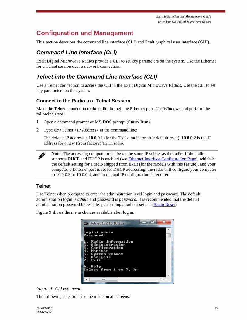
Exalt Installation and Management Guide
ExtendAir G2 Digital Microwave Radios
208871-002 242014-05-27
Configuration and ManagementThis section describes the command line interface (CLI) and Exalt graphical user interface (GUI).
Command Line Interface (CLI)
Exalt Digital Microwave Radios provide a CLI to set key parameters on the system. Use the Ethernet for a Telnet session over a network connection.
Telnet into the Command Line Interface (CLI)
Use a Telnet connection to access the CLI in the Exalt Digital Microwave Radios. Use the CLI to set key parameters on the system.
Connect to the Radio in a Telnet Session
Make the Telnet connection to the radio through the Ethernet port. Use Windows and perform the following steps:
1 Open a command prompt or MS-DOS prompt (Start>Run).
2 Type C:\>Telnet <IP Address> at the command line:
The default IP address is 10.0.0.1 (for the Tx Lo radio, or after default reset). 10.0.0.2 is the IP address for a new (from factory) Tx Hi radio.
Telnet
Use Telnet when prompted to enter the administration level login and password. The default administration login is admin and password is password. It is recommended that the default administration password be reset by performing a radio reset (see Radio Reset).
Figure 9 shows the menu choices available after log in.
Figure 9 CLI root menu
The following selections can be made on all screens:
Note: The accessing computer must be on the same IP subnet as the radio. If the radio supports DHCP and DHCP is enabled (see Ethernet Interface Configuration Page), which is the default setting for a radio shipped from Exalt (for the models with this feature), and your computer’s Ethernet port is set for DHCP addressing, the radio will configure your computer to 10.0.0.3 or 10.0.0.4, and no manual IP configuration is required.

Exalt Installation and Management Guide
ExtendAir G2 Digital Microwave Radios
25 208871-002
2014-05-27
• 0 = back to previous screen
• h = help
• Ctrl+\ (control and backslash keys) = exit session
Exalt Graphical User Interface (GUI)
The Exalt GUI is the primary user interface for configuring and troubleshooting the radio and radio system. A computer or hand-held device with a conventional HTML browser and Ethernet port is required. Microsoft Internet Explorer is the preferred browser. Netscape, Mozilla, and Firefox are also supported.
Preparing to Connect
If the radios are new, both radios are preconfigured as Tx Lo and Tx Hi with default IP addresses of 10.0.0.1 and 10.0.0.2, respectively. If the radios are not new, the IP addresses and Hi/Lo and diplexer configurations may need to be changed. The initial priority is to connect to the radio’s management system to completely configure the radio. Assign the radios different IP addresses, unique to each radio. There are two ways to change the IP address:
1 Reset the radio to the critical default factory settings (see Radio Reset).
2 Connect to the GUI using the default IP address (10.0.0.1 or 10.0.0.2), and change the IP address through the GUI interface.
Make Connections
It is recommended that one radio at a time be configured, on a bench, before taking the radios to the field for installation. Terminate the RF connector with a 50-Ohm termination or a fixed attenuator of at least 20dB (see Power).
Once connected to the radio using Ethernet, log in to the Exalt GUI.
Log In
Use the following steps to log in to the Exalt GUI.
Note: To connect to the radio’s Ethernet port and use the GUI interface, the accessing computer must match the radio’s IP address subnet. It is therefore necessary to either change the radio’s IP address through the CLI to match the subnet of the computer, or change the computer’s IP address to match the subnet of the radio (such as, a computer IP address of 10.0.0.10 if trying to connect to a radio set to the factory default IP address of 10.0.0.1).
If the radio supports DHCP and DHCP is enabled (see Ethernet Interface Configuration Page), which is the default setting for a radio shipped from Exalt (for the models with this feature), and your computer’s Ethernet port is set for DHCP addressing, the radio will configure your computer to 10.0.0.3 or 10.0.0.4, and no manual IP configuration is required.
CAUTION! Do not connect the radios in a back-to-back configuration unless the IP addresses of the two radios are verified as different from each other.
Note: The IP address subnet of the accessing computer must match the radio’s IP address subnet to connect using Ethernet.

Exalt Installation and Management Guide
ExtendAir G2 Digital Microwave Radios
208871-002 262014-05-27
1 Open a browser window.
Microsoft Internet Explorer is the recommended browser. Netscape, Mozilla, and Firefox are also supported. If there are issues with your browser, please report it to Exalt Customer Care. You may be required to use a different browser to immediately overcome issues.
2 Type the IP address of the radio in the address bar.
Figure 10 Initiating the browser connection
The following window displays after pressing the Enter key or clicking the Go button in the browser window.
Figure 11 Browser Login screen
Login Privileges
There are two levels of login privileges:
• Administrator (admin) – assigned complete permissions to view, edit, and configure
• User (user) – assigned limited, view-only permissions with no edit or configuration rights
The default login names and passwords are as follows:
Administrator login credentials are required for configuration purposes. Type the user name and passwords for Administrator level and click OK. The following screen displays.
Table 5 Default login information
Privilege level User name Default password
Administrator admin password
User user password
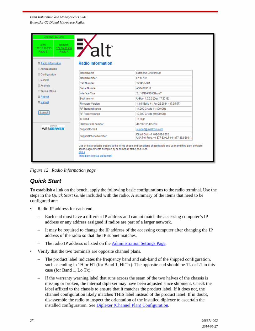
Exalt Installation and Management Guide
ExtendAir G2 Digital Microwave Radios
27 208871-002
2014-05-27
Figure 12 Radio Information page
Quick Start
To establish a link on the bench, apply the following basic configurations to the radio terminal. Use the steps in the Quick Start Guide included with the radio. A summary of the items that need to be configured are:
• Radio IP address for each end.
– Each end must have a different IP address and cannot match the accessing computer’s IP address or any address assigned if radios are part of a larger network.
– It may be required to change the IP address of the accessing computer after changing the IP address of the radio so that the IP subnet matches.
– The radio IP address is listed on the Administration Settings Page.
• Verify that the two terminals are opposite channel plans.
– The product label indicates the frequency band and sub-band of the shipped configuration, such as ending in 1H or H1 (for Band 1, Hi Tx). The opposite end should be 1L or L1 in this case (for Band 1, Lo Tx).
– If the warranty warning label that runs across the seam of the two halves of the chassis is missing or broken, the internal diplexer may have been adjusted since shipment. Check the label affixed to the chassis to ensure that it matches the product label. If it does not, the channel configuration likely matches THIS label instead of the product label. If in doubt, disassemble the radio to inspect the orientation of the installed diplexer to ascertain the installed configuration. See Diplexer (Channel Plan) Configuration.
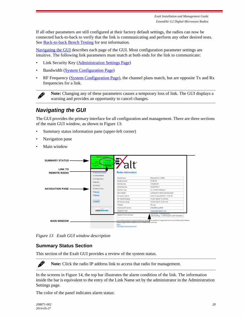
Exalt Installation and Management Guide
ExtendAir G2 Digital Microwave Radios
208871-002 282014-05-27
If all other parameters are still configured at their factory default settings, the radios can now be connected back-to-back to verify that the link is communicating and perform any other desired tests. See Back-to-back Bench Testing for test information.
Navigating the GUI describes each page of the GUI. Most configuration parameter settings are intuitive. The following link parameters must match at both ends for the link to communicate:
• Link Security Key (Administration Settings Page)
• Bandwidth (System Configuration Page)
• RF Frequency (System Configuration Page), the channel plans match, but are opposite Tx and Rx frequencies for a link.
Navigating the GUI
The GUI provides the primary interface for all configuration and management. There are three sections of the main GUI window, as shown in Figure 13:
• Summary status information pane (upper-left corner)
• Navigation pane
• Main window
Figure 13 Exalt GUI window description
Summary Status Section
This section of the Exalt GUI provides a review of the system status.
In the screens in Figure 14, the top bar illustrates the alarm condition of the link. The information inside the bar is equivalent to the entry of the Link Name set by the administrator in the Administration Settings page.
The color of the panel indicates alarm status:
Note: Changing any of these parameters causes a temporary loss of link. The GUI displays a warning and provides an opportunity to cancel changes.
Note: Click the radio IP address link to access that radio for management.
SUMMARY STATUS
NAVIGATION PANE
MAIN WINDOW
LINK TO
REMOTE RADIO
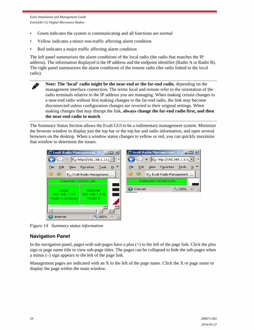
Exalt Installation and Management Guide
ExtendAir G2 Digital Microwave Radios
29 208871-002
2014-05-27
• Green indicates the system is communicating and all functions are normal
• Yellow indicates a minor non-traffic affecting alarm condition
• Red indicates a major traffic affecting alarm condition
The left panel summarizes the alarm conditions of the local radio (the radio that matches the IP address). The information displayed is the IP address and the endpoint identifier (Radio A or Radio B). The right panel summarizes the alarm conditions of the remote radio (the radio linked to the local radio).
The Summary Status Section allows the Exalt GUI to be a rudimentary management system. Minimize the browser window to display just the top bar or the top bar and radio information, and open several browsers on the desktop. When a window status changes to yellow or red, you can quickly maximize that window to determine the issues.
Figure 14 Summary status information
Navigation Panel
In the navigation panel, pages with sub-pages have a plus (+) to the left of the page link. Click the plus sign or page name title to view sub-page titles. The pages can be collapsed to hide the sub-pages when a minus (–) sign appears to the left of the page link.
Management pages are indicated with an X to the left of the page name. Click the X or page name to display the page within the main window.
Note: The ‘local’ radio might be the near-end or the far-end radio, depending on the management interface connection. The terms local and remote refer to the orientation of the radio terminals relative to the IP address you are managing. When making certain changes to a near-end radio without first making changes to the far-end radio, the link may become disconnected unless configuration changes are reverted to their original settings. When making changes that may disrupt the link, always change the far-end radio first, and then the near-end radio to match.
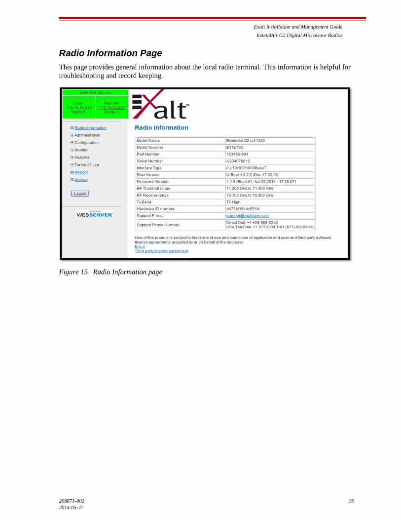
Exalt Installation and Management Guide
ExtendAir G2 Digital Microwave Radios
208871-002 302014-05-27
Radio Information Page
This page provides general information about the local radio terminal. This information is helpful for troubleshooting and record keeping.
Figure 15 Radio Information page

Exalt Installation and Management Guide
ExtendAir G2 Digital Microwave Radios
31 208871-002
2014-05-27
Administration Settings Page
This page contains general parameters for the radio system. The Current Value column lists actual settings. Enter desired changes in the New Value column. After entering all desired changes, click the Update button to accept and enable changes.
Figure 16 Administration Settings page
Most entries on this page are self-explanatory. The following lists unique or important parameters.
• Fill in the date and time fields as soon as practical. Events are captured with time/date stamps, which is valuable information for troubleshooting.
• Set the Link Security Key to something other than the factory default setting (12 characters, all zeros) at each end. The link security key must match at both sides of the link. If the security key remains at the factory setting, the radio link is open to sabotage by a party with the same radio model. Each link should have a unique security key. If using the same security key for every link in the network, the radio could link to any other radio with the same security key. This is problematic in multi-radio networks.
– Note that the security key must be exactly 12 characters. Any alphanumeric character can be used. The link security key is case sensitive.
• Reset the admin and user passwords. These passwords should not match. If the admin password remains at the factory default setting, it provides an opportunity for random reassignment by a network-connected user.
Note: Changing the link security key interrupts transmission until the opposite end is changed to match. Always change the far-end radio first, and then change the near-end radio.
Exalt Installation and Management Guide
ExtendAir G2 Digital Microwave Radios
208871-002 322014-05-27
– The new password must be entered twice. If the passwords do not match and the Update button clicked, the password is not changed and remains set to the previous password.
• Enter the license key provided by Exalt to access extended features or diagnostic capabilities. Click Update to accept the changes and enable the new features. License keys are issued by radio serial number, so ensure that the license key used was issued for this particular radio.
• AES (Advance Encryption Standard) can be implemented to provide additional data security for the wireless link. This function requires an upgrade license key (purchased separately). Both radios in the link must have a valid AES upgrade license key to implement AES. Different bit-length encryption license keys (for example, 128-bit and 256-bit) are also available, depending on model type. If the required upgrade license key is present, simply insert a matching hexadecimal string on both terminals and select the Enable AES On option for AES encryption. Note that similar to the administration and user passwords, the AES string must be entered twice for each terminal.
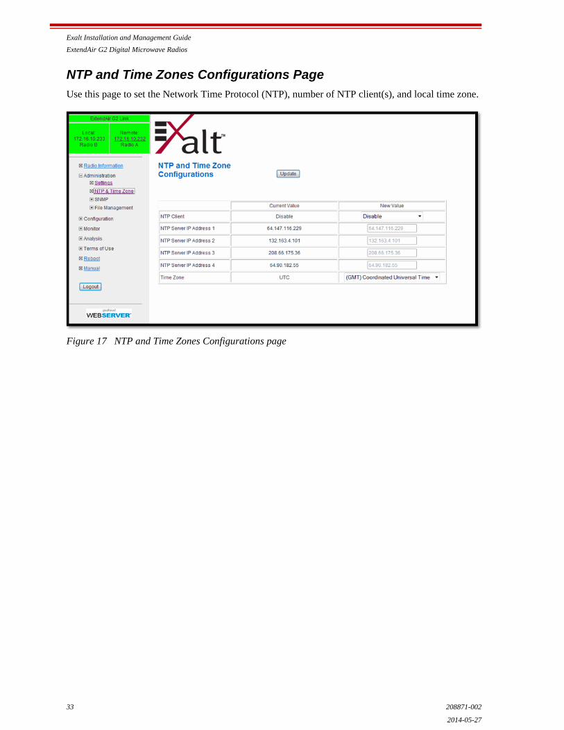
Exalt Installation and Management Guide
ExtendAir G2 Digital Microwave Radios
33 208871-002
2014-05-27
NTP and Time Zones Configurations Page
Use this page to set the Network Time Protocol (NTP), number of NTP client(s), and local time zone.
Figure 17 NTP and Time Zones Configurations page

Exalt Installation and Management Guide
ExtendAir G2 Digital Microwave Radios
208871-002 342014-05-27
Simple Network Management Protocol (SNMP) Configuration
This page allows the enabling and disabling of the Simple Network Management Protocol (SNMP) functions. Use SNMP to manage networked devices and execute the following functions:
• GET: Obtain information from the device, such as a configuration setting or parameter.
• SET: Change a configuration setting on the device.
• TRAP: The device proactively informs the management station of a change of state, usually used for critical alarms or warnings. See SNMP Traps.
Figure 18 SNMP Configuration page
One feature of the SNMP implementation is that system configuration changes do not take effect using the SET command. Instead, groups of configuration settings can be preconfigured for global change, and a single ‘Save’ (Commit) command implements all changes.
When some parameters are changed, a link may drop and/or management control lost. MIB files allow many parameters to be set at once, allowing only a temporarily dropped link or management control issue. The opposite end radio can be quickly reconfigured, with little downtime for the link and management control. The save (Commit) command is similar to the Update button.
Dropped links or management control issues do not occur with every parameter change. Many configuration changes do not impact traffic or management access.
ExtendAir G2 radios utilize SNMPv3, a high security version of SNMP, to ensure secure access to and storing of management data. The SNMPv3 security string matches the admin and user passwords. Passwords must be eight characters or longer.
The SNMP MIBs are organized similar to the GUI. Become familiar with the GUI before using the SNMP function.
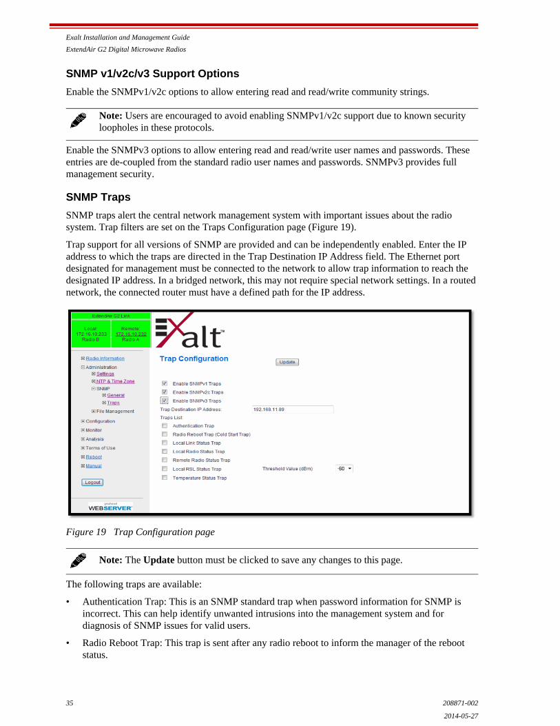
Exalt Installation and Management Guide
ExtendAir G2 Digital Microwave Radios
35 208871-002
2014-05-27
SNMP v1/v2c/v3 Support Options
Enable the SNMPv1/v2c options to allow entering read and read/write community strings.
Enable the SNMPv3 options to allow entering read and read/write user names and passwords. These entries are de-coupled from the standard radio user names and passwords. SNMPv3 provides full management security.
SNMP Traps
SNMP traps alert the central network management system with important issues about the radio system. Trap filters are set on the Traps Configuration page (Figure 19).
Trap support for all versions of SNMP are provided and can be independently enabled. Enter the IP address to which the traps are directed in the Trap Destination IP Address field. The Ethernet port designated for management must be connected to the network to allow trap information to reach the designated IP address. In a bridged network, this may not require special network settings. In a routed network, the connected router must have a defined path for the IP address.
Figure 19 Trap Configuration page
The following traps are available:
• Authentication Trap: This is an SNMP standard trap when password information for SNMP is incorrect. This can help identify unwanted intrusions into the management system and for diagnosis of SNMP issues for valid users.
• Radio Reboot Trap: This trap is sent after any radio reboot to inform the manager of the reboot status.
Note: Users are encouraged to avoid enabling SNMPv1/v2c support due to known security loopholes in these protocols.
Note: The Update button must be clicked to save any changes to this page.

Exalt Installation and Management Guide
ExtendAir G2 Digital Microwave Radios
208871-002 362014-05-27
• Local/Remote Link Status Trap: This trap is sent when Link is in errored state (equivalent to the Link LED on the radio front panel or the Link status bar in the upper-left of the Exalt GUI window).
• Local/Remote Status Trap: This trap is sent when Status is in errored state (equivalent to the Status LED on the front panel or the radio status box in the upper-left of the Exalt GUI window).
• Local RSL Status Trap: This trap is sent when the local RSL drops below the value set in the Threshold Value (dBm) field. Buffers are provided so that continuous traps are not sent if the RSL is bouncing near the set threshold value. This trap is reset only if the RSL rises to 3dBm above the set threshold value and then drops below that value. Exalt recommends that this trap be set to a value 5dBm or 10dBm above the threshold as a warning that the system has faded and may be approaching an outage.
• Temperature Status Trap: This trap is sent when the internal temperature reaches the warning point. This conveys that the external temperature control is in a fault state. Buffers are applied to this trap to avoid multiple traps when the temperature remains near the warning point.
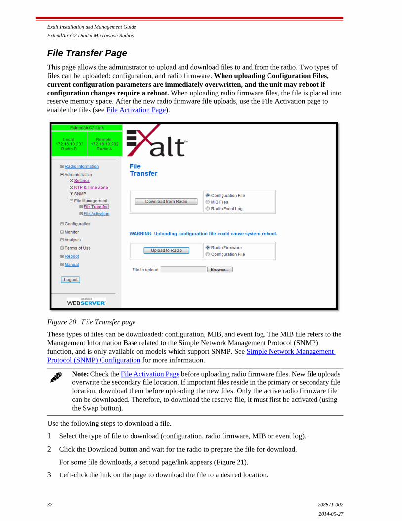
Exalt Installation and Management Guide
ExtendAir G2 Digital Microwave Radios
37 208871-002
2014-05-27
File Transfer Page
This page allows the administrator to upload and download files to and from the radio. Two types of files can be uploaded: configuration, and radio firmware. When uploading Configuration Files, current configuration parameters are immediately overwritten, and the unit may reboot if configuration changes require a reboot. When uploading radio firmware files, the file is placed into reserve memory space. After the new radio firmware file uploads, use the File Activation page to enable the files (see File Activation Page).
Figure 20 File Transfer page
These types of files can be downloaded: configuration, MIB, and event log. The MIB file refers to the Management Information Base related to the Simple Network Management Protocol (SNMP) function, and is only available on models which support SNMP. See Simple Network Management Protocol (SNMP) Configuration for more information.
Use the following steps to download a file.
1 Select the type of file to download (configuration, radio firmware, MIB or event log).
2 Click the Download button and wait for the radio to prepare the file for download.
For some file downloads, a second page/link appears (Figure 21).
3 Left-click the link on the page to download the file to a desired location.
Note: Check the File Activation Page before uploading radio firmware files. New file uploads overwrite the secondary file location. If important files reside in the primary or secondary file location, download them before uploading the new files. Only the active radio firmware file can be downloaded. Therefore, to download the reserve file, it must first be activated (using the Swap button).
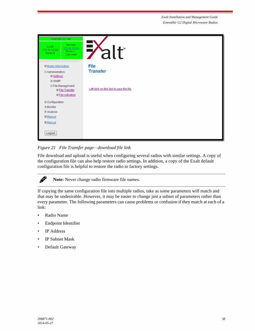
Exalt Installation and Management Guide
ExtendAir G2 Digital Microwave Radios
208871-002 382014-05-27
Figure 21 File Transfer page—download file link
File download and upload is useful when configuring several radios with similar settings. A copy of the configuration file can also help restore radio settings. In addition, a copy of the Exalt default configuration file is helpful to restore the radio to factory settings.
If copying the same configuration file into multiple radios, take as some parameters will match and that may be undesirable. However, it may be easier to change just a subset of parameters rather than every parameter. The following parameters can cause problems or confusion if they match at each of a link:
• Radio Name
• Endpoint Identifier
• IP Address
• IP Subnet Mask
• Default Gateway
Note: Never change radio firmware file names.
Exalt Installation and Management Guide
ExtendAir G2 Digital Microwave Radios
39 208871-002
2014-05-27
The following parameters can match at both ends of the link:
• Link Name
• Link Security Key (although each link should be different)
• Admin and User passwords
• Bandwidth
• RF Frequency
• Ethernet configurations
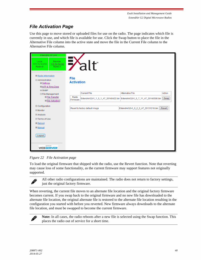
Exalt Installation and Management Guide
ExtendAir G2 Digital Microwave Radios
208871-002 402014-05-27
File Activation Page
Use this page to move stored or uploaded files for use on the radio. The page indicates which file is currently in use, and which file is available for use. Click the Swap button to place the file in the Alternative File column into the active state and move the file in the Current File column to the Alternative File column.
Figure 22 File Activation page
To load the original firmware that shipped with the radio, use the Revert function. Note that reverting may cause loss of some functionality, as the current firmware may support features not originally supported.
When reverting, the current file moves to an alternate file location and the original factory firmware becomes current. If you swap back to the original firmware and no new file has downloaded to the alternate file location, the original alternate file is restored to the alternate file location resulting in the configuration you started with before you reverted. New firmware always downloads to the alternate file location, and must be swapped to become the current firmware.
All other radio configurations are maintained. The radio does not return to factory settings, just the original factory firmware.
Note: In all cases, the radio reboots after a new file is selected using the Swap function. This places the radio out of service for a short time.
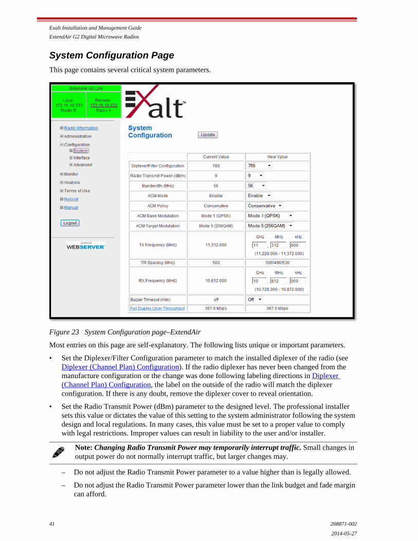
Exalt Installation and Management Guide
ExtendAir G2 Digital Microwave Radios
41 208871-002
2014-05-27
System Configuration Page
This page contains several critical system parameters.
Figure 23 System Configuration page–ExtendAir
Most entries on this page are self-explanatory. The following lists unique or important parameters.
• Set the Diplexer/Filter Configuration parameter to match the installed diplexer of the radio (see Diplexer (Channel Plan) Configuration). If the radio diplexer has never been changed from the manufacture configuration or the change was done following labeling directions in Diplexer (Channel Plan) Configuration, the label on the outside of the radio will match the diplexer configuration. If there is any doubt, remove the diplexer cover to reveal orientation.
• Set the Radio Transmit Power (dBm) parameter to the designed level. The professional installer sets this value or dictates the value of this setting to the system administrator following the system design and local regulations. In many cases, this value must be set to a proper value to comply with legal restrictions. Improper values can result in liability to the user and/or installer.
– Do not adjust the Radio Transmit Power parameter to a value higher than is legally allowed.
– Do not adjust the Radio Transmit Power parameter lower than the link budget and fade margin can afford.
Note: Changing Radio Transmit Power may temporarily interrupt traffic. Small changes in output power do not normally interrupt traffic, but larger changes may.
Exalt Installation and Management Guide
ExtendAir G2 Digital Microwave Radios
208871-002 422014-05-27
• Set the Bandwidth (MHz) parameter to the value assigned to the radio license. The value of this is determined in the design/engineering stage. The Bandwidth parameter must also match at both ends of the link. In conjunction with the Mode parameter, the Bandwidth parameter directly relates to the capacity supported.
Adaptive Coded Modulation (ACM) allows the radio to reduce throughput as link conditions fall below what can be supported during normal operation. The advantage is that instead of the link being down or highly errored, the link remains up for longer periods, but with reduced throughput.
• ACM Mode parameter enables or disables ACM. Some regulatory environments may not allow ACM or may require special licensing. Check your local regulations before enabling this feature.
• ACM Policy parameter selects the modulation to run and how fast to switch between settings.
– Aggressive settings switch the radio from modulation to modulation at the moment that the signal-to-noise ratio allows. This can result in rapidly changing throughput characteristics, but always provides the highest throughput, even if the currently selected setting is not error-free.
– Conservative applies hysteresis to the switching decision, waiting longer to make a change in the ‘upward’ direction. Switching to a lower modulation is instantaneous, but the radio ‘waits’ to switch back to a higher modulation state until the signal-to-noise ratio is above the threshold for that setting. The result is slightly slower changes between modulations and less overall switching (which could be less disruptive to some network operations).
• ACM Base Modulation parameter sets the minimum modulation for the radio to select. There are cases where regulatory limits may apply that govern the minimum modulation that can be used, which is sometimes based on licensing. Check your local regulations before deciding this parameter setting.
• ACM Target Modulation parameter sets the desired modulation for the link under normal unfaded conditions. The radio attempts to remain in mode at all times, unless link conditions cannot support it. Again, licensing and/or local regulations may govern the maximum setting for this parameter.
• Set the Mode parameter to the designed selection. The value of this setting is determined in the design/engineering stage and by the licensing process. The Mode parameter must match at both ends of the link. In conjunction with the Bandwidth parameter, the Mode parameter setting directly relates to the capacity of the system, as well as critical RF parameters, including receiver threshold, carrier-to-interference ratio, and in some cases, maximum radio transmit power.
Note: The link may be lost and unrecoverable through GUI control. If the link is lost due to reduction of Radio Transmit Power, travel to the radio location(s) may be required to reset the value.
Note: Changing Bandwidth will temporarily interrupt traffic. The Bandwidth parameter must match at each end. Adjust the far-end radio first, and then the near-end radio. Changing Bandwidth changes the radio’s threshold. A narrower bandwidth has better threshold performance and improved interference immunity, therefore if changing to a wider bandwidth, there is an opportunity that the link may be lost and unrecoverable through GUI control. Check the available fade margin to determine if the impact to threshold and increased bandwidth is acceptable to maintain the link and the desired performance. If the link is lost due to increasing the Bandwidth parameter, travel to the radio location(s) may be required to reset the value.
Exalt Installation and Management Guide
ExtendAir G2 Digital Microwave Radios
43 208871-002
2014-05-27
• Set the TX Frequency (GHz) parameter and Rx Frequency (GHz) parameter to the licensed center frequencies. The frequencies must match the same pair at both ends of the link, but in opposite Tx/Rx orientation.
• The Transmitter/Receiver (TR) frequency spacing is automatically determined based on the frequency settings. This is reported to verify the intended frequency settings, as a confirmation to proper input.
• Buzzer Timeout (minutes) parameter creates an audio signal for antenna alignment. Turn on the buzzer continuously during antenna alignment or preset a period of time that the buzzer will sound. If the buzzer stops before alignment activities are complete, change the selection and press the Update button or select the ON option until alignment activities are complete.
• Full-Duplex Throughput parameter provides information about user capacity of the wireless link, in the current configuration. The ‘new value’ column reflects throughput if changes are made to Bandwidth or Mode. Click the “Full-Duplex User Throughput” link for details on how capacity information is determined.
Note: Changing Mode will temporarily interrupt traffic. The Mode setting must match at each end. Adjust the far-end radio first, and then the near-end radio. Changing Mode changes the radio’s threshold, carrier-to-interference ratio, and also may have impact on the Radio Transmit Power. A lower mode has better threshold performance and carrier-to-interference ratio, and in some cases, higher output power, therefore if changing to a higher mode (for example, from Mode 1 to Mode 2), there is an opportunity that the link may be lost and unrecoverable through GUI control. Check the available fade margin and interference profile, and determine if the impact to RF performance is sufficient to maintain the link and desired performance. If the link is lost due to increasing the Mode parameter, travel to the radio location(s) may be required to reset the value.
Note: Changing RF Frequency will temporarily interrupt traffic. The RF Frequency parameter pair must be opposite at each end. Adjust the far-end radio first, and then the near-end radio. If the link is lost due to changing the RF Frequency parameter, travel to the radio location(s) may be required to reset the value.

Exalt Installation and Management Guide
ExtendAir G2 Digital Microwave Radios
208871-002 442014-05-27
Ethernet Interface Configuration Page
This page allows the administrator to set the muting, alarm, and duplex settings of both the Ethernet connection and allows determination of the management information for in-band (carried over the air and available from both Ethernet connectors on either end of the link) or out-of-band (not carried over the air and only available from the local PoE connector).
Figure 24 Ethernet Interface Configuration page
To ignore Ethernet alarms, disable the alarming of the connector. Muting a connection is desirable when connected equipment senses Ethernet signaling and makes decisions (such as, spanning tree protocol enable) based on the Ethernet signal. The ETH1 port cannot be muted, as it is always used for primary management and PoE.
It may be desirable to disable the alarming of any connector if it is not used.
The Management parameter allows determination of management information using the following management modes:
• In-band: Management traffic is carried over the air and is available from all connectors on either end of the link.
• Out-of-band: Management traffic is not carried over the air and is only available from the port(s) configured for Management.
• Port-to-Port: Management traffic remains separate from data traffic without requiring out-of-band management or VLAN configuration. This allows any Ethernet port on the link to be logically mapped to the same port at the other end of the link without requiring VLANs to be configured. The traffic passing through these mapped ports is not accessible from any of the other available Ethernet ports on either side of the link.
• Set the Ethernet ports on the radio and connected equipment to 100/full-duplex for best performance. If the Ethernet ports are set to auto-negotiation, poor throughput performance may be a result, as well as intermittent disconnections of the Ethernet connection.
Exalt Installation and Management Guide
ExtendAir G2 Digital Microwave Radios
45 208871-002
2014-05-27
• The Flow Control setting allows the enabling of 802.3 Ethernet flow control. This feature is selectable on all Ethernet interface ports individually, and enables flow control signaling from the radio to the connected network device. ‘Pause’ packets are issued when incoming traffic capacity is greater than current capacity. This feature is only operational when used in conjunction with Rate Limiting and/or QoS.
• The Alarm function can be enabled or disabled for each port. Generally, all constantly connected port alarms should be enabled, and unused or maintenance-only ports should have alarms disabled.
• For models with multiple Ethernet ports, the Mute setting allows signaling to connected network devices when the radio link is down such as for spanning tree protocol.
• When enabled, the DHCP feature provides a basic DHCP function to ease interfacing with a computer. DHCP is enabled by default. If the Ethernet port on the computer is set for DHCP addressing, on radio bootup (for up to 10 minutes) or when an Ethernet link is sensed for a management port, the radio provides an IP address to the computer that is two digits higher than the radio’s IP address (for example, if the radio’s IP address is 10.0.0.1, the computer’s IP address will be 10.0.0.3). The radio also senses any DHCP server on the network and if detected, mutes its own internal DHCP function.
Auto-negotiation is recommended when connected to other 1000BaseT connections. It can also be hard set to match the connected network device, but in some cases, if it is set to 1000BaseT/Full, it may become impossible for the radio to communicate with a 100BaseT device.
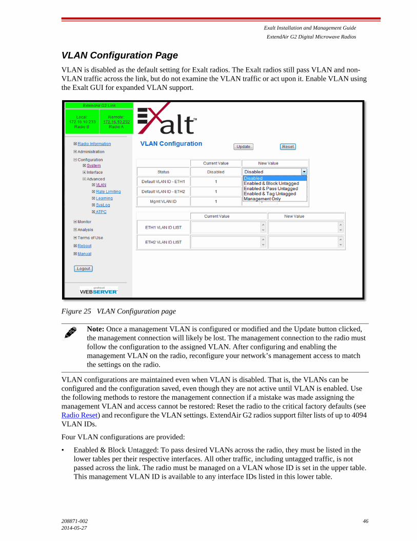
Exalt Installation and Management Guide
ExtendAir G2 Digital Microwave Radios
208871-002 462014-05-27
VLAN Configuration Page
VLAN is disabled as the default setting for Exalt radios. The Exalt radios still pass VLAN and non-VLAN traffic across the link, but do not examine the VLAN traffic or act upon it. Enable VLAN using the Exalt GUI for expanded VLAN support.
Figure 25 VLAN Configuration page
VLAN configurations are maintained even when VLAN is disabled. That is, the VLANs can be configured and the configuration saved, even though they are not active until VLAN is enabled. Use the following methods to restore the management connection if a mistake was made assigning the management VLAN and access cannot be restored: Reset the radio to the critical factory defaults (see Radio Reset) and reconfigure the VLAN settings. ExtendAir G2 radios support filter lists of up to 4094 VLAN IDs.
Four VLAN configurations are provided:
• Enabled & Block Untagged: To pass desired VLANs across the radio, they must be listed in the lower tables per their respective interfaces. All other traffic, including untagged traffic, is not passed across the link. The radio must be managed on a VLAN whose ID is set in the upper table. This management VLAN ID is available to any interface IDs listed in this lower table.
Note: Once a management VLAN is configured or modified and the Update button clicked, the management connection will likely be lost. The management connection to the radio must follow the configuration to the assigned VLAN. After configuring and enabling the management VLAN on the radio, reconfigure your network’s management access to match the settings on the radio.
Exalt Installation and Management Guide
ExtendAir G2 Digital Microwave Radios
47 208871-002
2014-05-27
• Enabled & Pass Untagged: To pass desired VLANs across the radio, they must be listed in the lower tables per their respective interfaces. All other VLAN traffic is not passed across the link, and untagged traffic is passed across the link with no changes. The radio must be managed on a VLAN whose ID is set in the upper table. This management VLAN ID is available to any interface IDs listed in this lower table.
• Enabled & Tag Untagged: To pass desired VLANs across the radio, they must be listed in the lower tables per their respective interfaces. All other VLAN traffic is not passed across the link, and untagged traffic is tagged with the programmed Default VLAN, per interface, as set in the upper table. Any interface requiring the default VLAN ID to pass must have the Default VLAN ID listed in the table below. The radio must be managed on a VLAN whose ID is set in the upper table. This management VLAN ID is available to any interface IDs listed in the lower table.
• Management only: All traffic is passed transparently, except the radio is managed on an assigned Management VLAN ID, as programmed in the upper table.
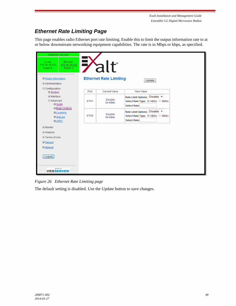
Exalt Installation and Management Guide
ExtendAir G2 Digital Microwave Radios
208871-002 482014-05-27
Ethernet Rate Limiting Page
This page enables radio Ethernet port rate limiting. Enable this to limit the output information rate to at or below downstream networking equipment capabilities. The rate is in Mbps or kbps, as specified.
Figure 26 Ethernet Rate Limiting page
The default setting is disabled. Use the Update button to save changes.
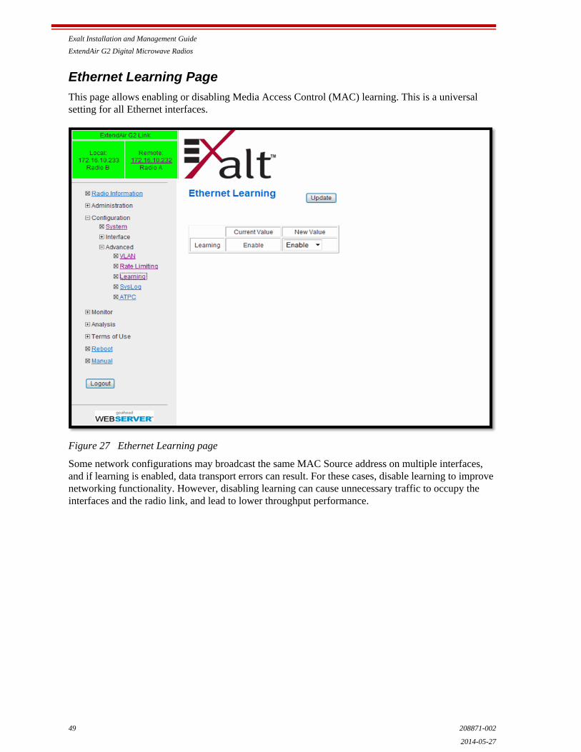
Exalt Installation and Management Guide
ExtendAir G2 Digital Microwave Radios
49 208871-002
2014-05-27
Ethernet Learning Page
This page allows enabling or disabling Media Access Control (MAC) learning. This is a universal setting for all Ethernet interfaces.
Figure 27 Ethernet Learning page
Some network configurations may broadcast the same MAC Source address on multiple interfaces, and if learning is enabled, data transport errors can result. For these cases, disable learning to improve networking functionality. However, disabling learning can cause unnecessary traffic to occupy the interfaces and the radio link, and lead to lower throughput performance.
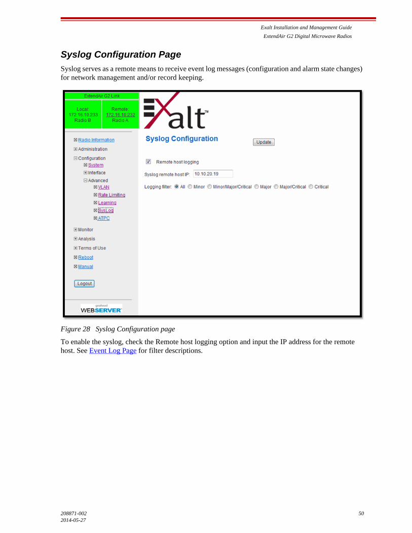
Exalt Installation and Management Guide
ExtendAir G2 Digital Microwave Radios
208871-002 502014-05-27
Syslog Configuration Page
Syslog serves as a remote means to receive event log messages (configuration and alarm state changes) for network management and/or record keeping.
Figure 28 Syslog Configuration page
To enable the syslog, check the Remote host logging option and input the IP address for the remote host. See Event Log Page for filter descriptions.
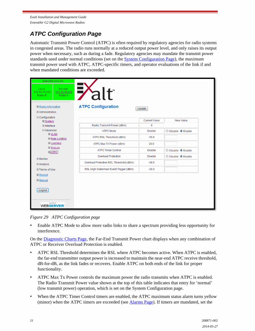
Exalt Installation and Management Guide
ExtendAir G2 Digital Microwave Radios
51 208871-002
2014-05-27
ATPC Configuration Page
Automatic Transmit Power Control (ATPC) is often required by regulatory agencies for radio systems in congested areas. The radio runs normally at a reduced output power level, and only raises its output power when necessary, such as during a fade. Regulatory agencies may mandate the transmit power standards used under normal conditions (set on the System Configuration Page), the maximum transmit power used with ATPC, ATPC-specific timers, and operator evaluations of the link if and when mandated conditions are exceeded.
Figure 29 ATPC Configuration page
• Enable ATPC Mode to allow more radio links to share a spectrum providing less opportunity for interference.
On the Diagnostic Charts Page, the Far-End Transmit Power chart displays when any combination of ATPC or Receiver Overload Protection is enabled.
• ATPC RSL Threshold determines the RSL where ATPC becomes active. When ATPC is enabled, the far-end transmitter output power is increased to maintain the near-end ATPC receive threshold, dB-for-dB, as the link fades or recovers. Enable ATPC on both ends of the link for proper functionality.
• ATPC Max Tx Power controls the maximum power the radio transmits when ATPC is enabled. The Radio Transmit Power value shown at the top of this table indicates that entry for ‘normal’ (low transmit power) operation, which is set on the System Configuration page.
• When the ATPC Timer Control timers are enabled, the ATPC maximum status alarm turns yellow (minor) when the ATPC timers are exceeded (see Alarms Page). If timers are mandated, set the
Exalt Installation and Management Guide
ExtendAir G2 Digital Microwave Radios
208871-002 522014-05-27
ATPC threshold as low as possible to reduce the time that ATPC is active. Current timer status is available on the ATPC Statistics Page. There are event log entries for all timer events.
• Receiver Overload Protection is similar to ATPC. It ensures that the maximum RSL is not exceeded by reducing transmit power of the far-end radio so that radio specifications are met. Receiver Overload Protection reduces far-end transmit power in un-faded conditions, or during up-fades, to ensure that the maximum input RSL specification is met at all times and not overloaded.
Receiver Overload Protection and ATPC can run independently or simultaneously. The radio runs at standard transmit power levels as long as the Overload Protection RSL threshold is not exceeded. If exceeded, the radio reduces the far-end transmit power to maintain the target RSL.
For links that normally run at a value exceeding radio specifications, use the licensed or maximum output power in the System Configuration setting and enable Receiver Overload Protection to attenuate the value for normal conditions and restore output power during fades.
• Set the RSL High Watermark Event Trigger value to a few dB above the normal (un-faded) RSL link or to a value at or above -33dBm, whichever is higher, to minimize the number of entries in the event log caused by running at or near the maximum RSL specification.
Note: Ensure that radio implementation meets local regulations. There may be limitations to the use of the Receiver Overload Protection feature. Consult your local regulatory authorities.
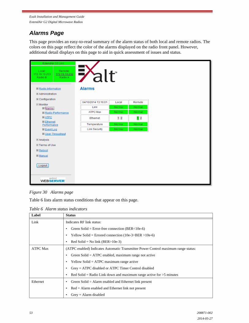
Exalt Installation and Management Guide
ExtendAir G2 Digital Microwave Radios
53 208871-002
2014-05-27
Alarms Page
This page provides an easy-to-read summary of the alarm status of both local and remote radios. The colors on this page reflect the color of the alarms displayed on the radio front panel. However, additional detail displays on this page to aid in quick assessment of issues and status.
Figure 30 Alarms page
Table 6 lists alarm status conditions that appear on this page.
Table 6 Alarm status indicatorsLabel Status
Link Indicates RF link status:
• Green Solid = Error-free connection (BER<10e-6)
• Yellow Solid = Errored connection (10e-3>BER >10e-6)
• Red Solid = No link (BER>10e-3)
ATPC Max (ATPC enabled) Indicates Automatic Transmitter Power Control maximum range status:
• Green Solid = ATPC enabled, maximum range not active
• Yellow Solid = ATPC maximum range active
• Grey = ATPC disabled or ATPC Timer Control disabled
• Red Solid = Radio Link down and maximum range active for >5 minutes
Ethernet • Green Solid = Alarm enabled and Ethernet link present
• Red = Alarm enabled and Ethernet link not present
• Grey = Alarm disabled
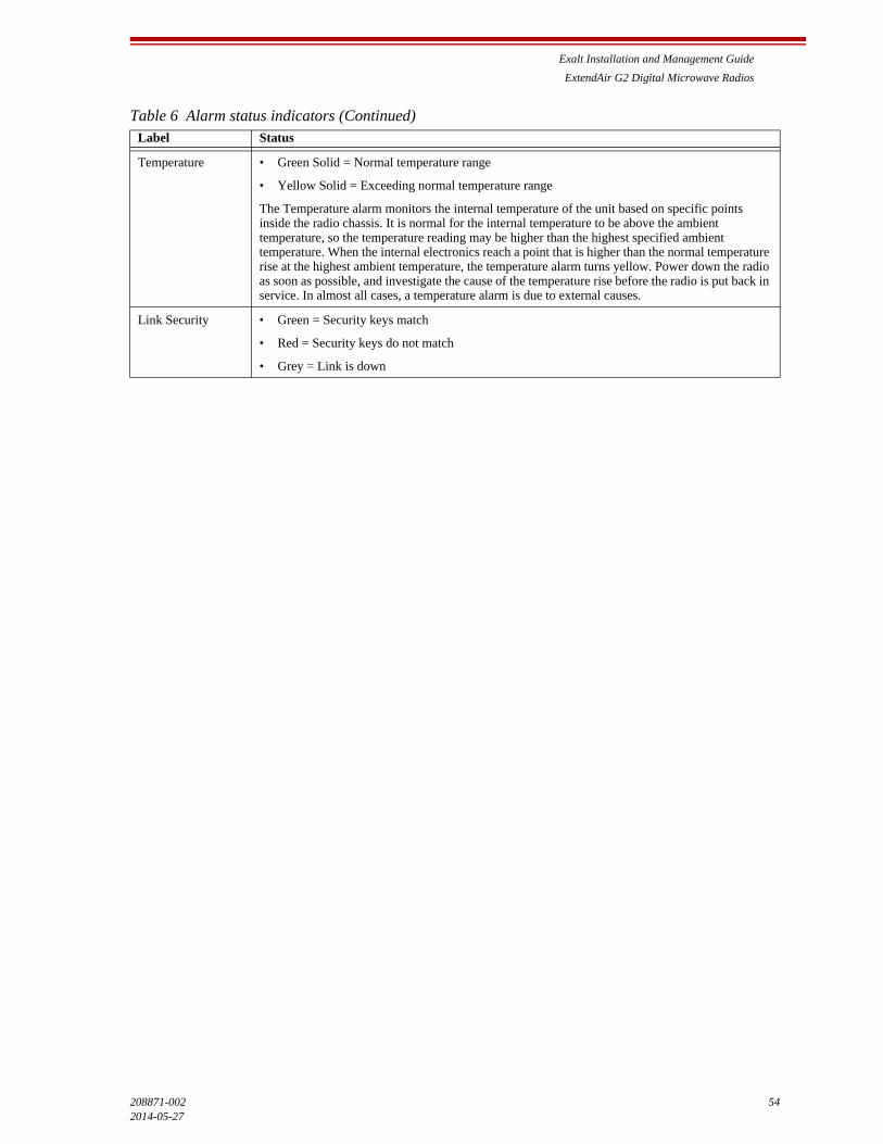
Exalt Installation and Management Guide
ExtendAir G2 Digital Microwave Radios
208871-002 542014-05-27
Temperature • Green Solid = Normal temperature range
• Yellow Solid = Exceeding normal temperature range
The Temperature alarm monitors the internal temperature of the unit based on specific points inside the radio chassis. It is normal for the internal temperature to be above the ambient temperature, so the temperature reading may be higher than the highest specified ambient temperature. When the internal electronics reach a point that is higher than the normal temperature rise at the highest ambient temperature, the temperature alarm turns yellow. Power down the radio as soon as possible, and investigate the cause of the temperature rise before the radio is put back in service. In almost all cases, a temperature alarm is due to external causes.
Link Security • Green = Security keys match
• Red = Security keys do not match
• Grey = Link is down
Table 6 Alarm status indicators (Continued)Label Status
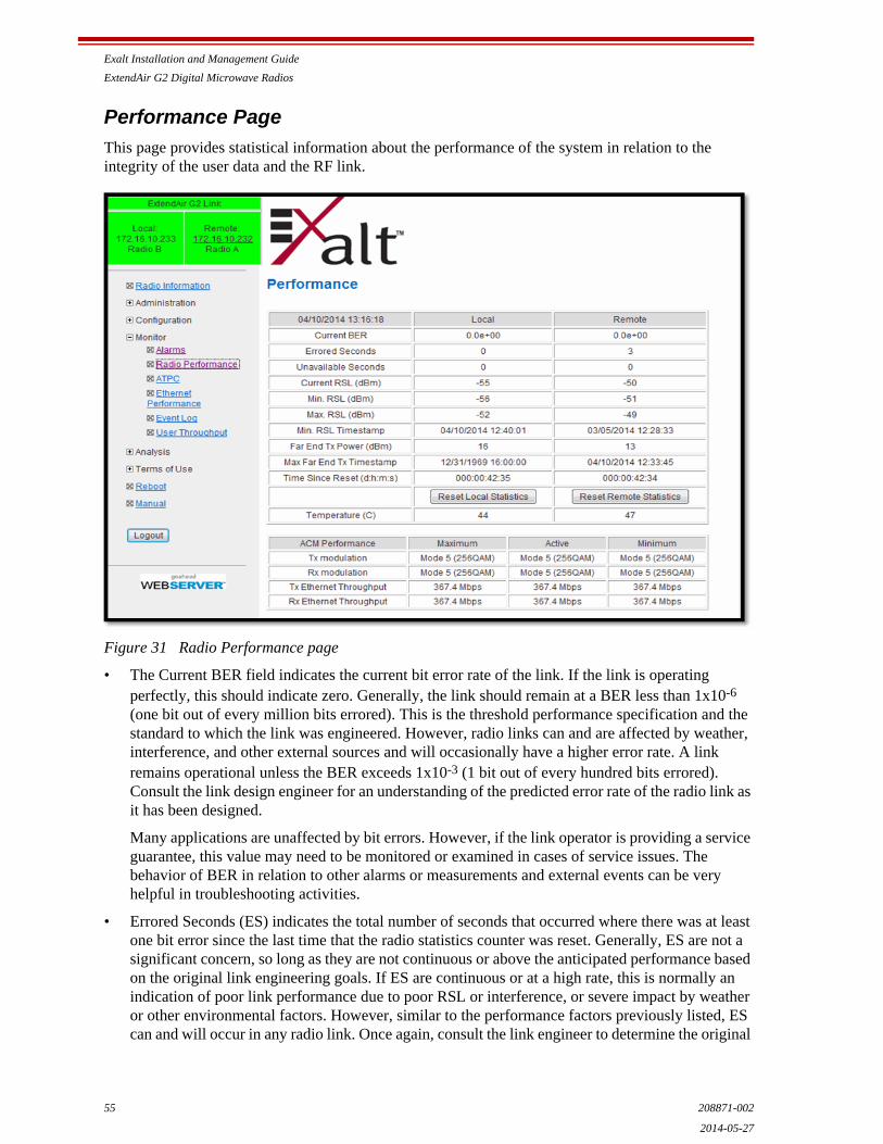
Exalt Installation and Management Guide
ExtendAir G2 Digital Microwave Radios
55 208871-002
2014-05-27
Performance Page
This page provides statistical information about the performance of the system in relation to the integrity of the user data and the RF link.
Figure 31 Radio Performance page
• The Current BER field indicates the current bit error rate of the link. If the link is operating perfectly, this should indicate zero. Generally, the link should remain at a BER less than 1x10⁻⁶ (one bit out of every million bits errored). This is the threshold performance specification and the standard to which the link was engineered. However, radio links can and are affected by weather, interference, and other external sources and will occasionally have a higher error rate. A link remains operational unless the BER exceeds 1x10⁻³ (1 bit out of every hundred bits errored). Consult the link design engineer for an understanding of the predicted error rate of the radio link as it has been designed.
Many applications are unaffected by bit errors. However, if the link operator is providing a service guarantee, this value may need to be monitored or examined in cases of service issues. The behavior of BER in relation to other alarms or measurements and external events can be very helpful in troubleshooting activities.
• Errored Seconds (ES) indicates the total number of seconds that occurred where there was at least one bit error since the last time that the radio statistics counter was reset. Generally, ES are not a significant concern, so long as they are not continuous or above the anticipated performance based on the original link engineering goals. If ES are continuous or at a high rate, this is normally an indication of poor link performance due to poor RSL or interference, or severe impact by weather or other environmental factors. However, similar to the performance factors previously listed, ES can and will occur in any radio link. Once again, consult the link engineer to determine the original
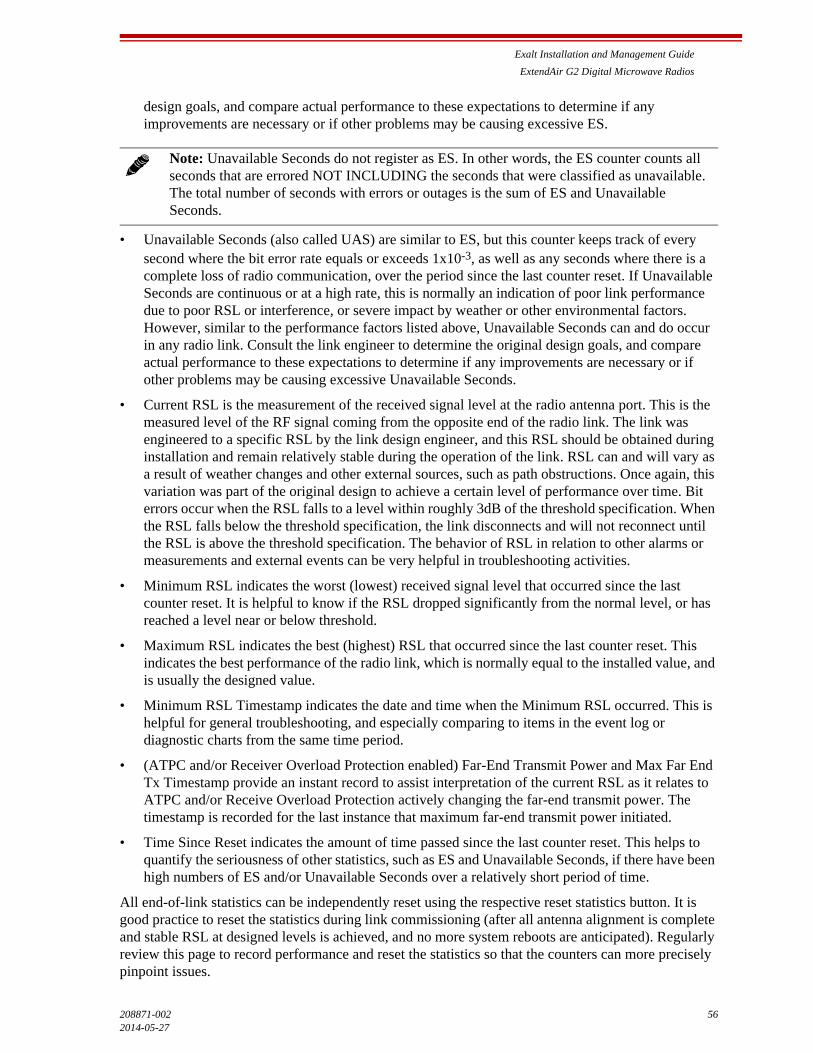
Exalt Installation and Management Guide
ExtendAir G2 Digital Microwave Radios
208871-002 562014-05-27
design goals, and compare actual performance to these expectations to determine if any improvements are necessary or if other problems may be causing excessive ES.
• Unavailable Seconds (also called UAS) are similar to ES, but this counter keeps track of every second where the bit error rate equals or exceeds 1x10⁻³, as well as any seconds where there is a complete loss of radio communication, over the period since the last counter reset. If Unavailable Seconds are continuous or at a high rate, this is normally an indication of poor link performance due to poor RSL or interference, or severe impact by weather or other environmental factors. However, similar to the performance factors listed above, Unavailable Seconds can and do occur in any radio link. Consult the link engineer to determine the original design goals, and compare actual performance to these expectations to determine if any improvements are necessary or if other problems may be causing excessive Unavailable Seconds.
• Current RSL is the measurement of the received signal level at the radio antenna port. This is the measured level of the RF signal coming from the opposite end of the radio link. The link was engineered to a specific RSL by the link design engineer, and this RSL should be obtained during installation and remain relatively stable during the operation of the link. RSL can and will vary as a result of weather changes and other external sources, such as path obstructions. Once again, this variation was part of the original design to achieve a certain level of performance over time. Bit errors occur when the RSL falls to a level within roughly 3dB of the threshold specification. When the RSL falls below the threshold specification, the link disconnects and will not reconnect until the RSL is above the threshold specification. The behavior of RSL in relation to other alarms or measurements and external events can be very helpful in troubleshooting activities.
• Minimum RSL indicates the worst (lowest) received signal level that occurred since the last counter reset. It is helpful to know if the RSL dropped significantly from the normal level, or has reached a level near or below threshold.
• Maximum RSL indicates the best (highest) RSL that occurred since the last counter reset. This indicates the best performance of the radio link, which is normally equal to the installed value, and is usually the designed value.
• Minimum RSL Timestamp indicates the date and time when the Minimum RSL occurred. This is helpful for general troubleshooting, and especially comparing to items in the event log or diagnostic charts from the same time period.
• (ATPC and/or Receiver Overload Protection enabled) Far-End Transmit Power and Max Far End Tx Timestamp provide an instant record to assist interpretation of the current RSL as it relates to ATPC and/or Receive Overload Protection actively changing the far-end transmit power. The timestamp is recorded for the last instance that maximum far-end transmit power initiated.
• Time Since Reset indicates the amount of time passed since the last counter reset. This helps to quantify the seriousness of other statistics, such as ES and Unavailable Seconds, if there have been high numbers of ES and/or Unavailable Seconds over a relatively short period of time.
All end-of-link statistics can be independently reset using the respective reset statistics button. It is good practice to reset the statistics during link commissioning (after all antenna alignment is complete and stable RSL at designed levels is achieved, and no more system reboots are anticipated). Regularly review this page to record performance and reset the statistics so that the counters can more precisely pinpoint issues.
Note: Unavailable Seconds do not register as ES. In other words, the ES counter counts all seconds that are errored NOT INCLUDING the seconds that were classified as unavailable. The total number of seconds with errors or outages is the sum of ES and Unavailable Seconds.

Exalt Installation and Management Guide
ExtendAir G2 Digital Microwave Radios
57 208871-002
2014-05-27
Note: Resetting statistics from one end also resets the statistics for the same radio at the opposite end. That is, if the Local statistics are reset, logging into the remote end shows the Remote statistics on that end (which is the local radio in the first condition) as being reset at the same time.
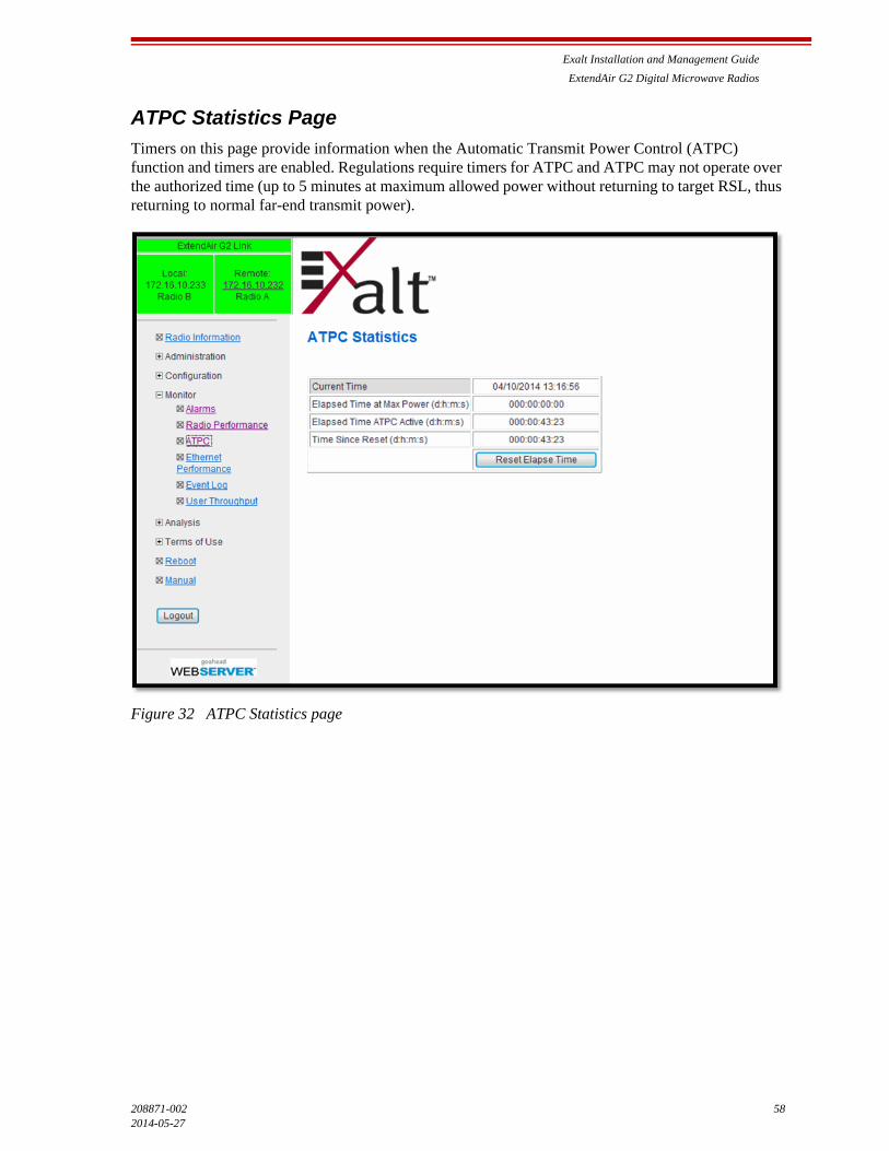
Exalt Installation and Management Guide
ExtendAir G2 Digital Microwave Radios
208871-002 582014-05-27
ATPC Statistics Page
Timers on this page provide information when the Automatic Transmit Power Control (ATPC) function and timers are enabled. Regulations require timers for ATPC and ATPC may not operate over the authorized time (up to 5 minutes at maximum allowed power without returning to target RSL, thus returning to normal far-end transmit power).
Figure 32 ATPC Statistics page

Exalt Installation and Management Guide
ExtendAir G2 Digital Microwave Radios
59 208871-002
2014-05-27
Ethernet Performance Page
This page displays statistics related to Ethernet traffic to assist with troubleshooting and for general performance monitoring. These statistics are aligned with the Remote Network Monitoring (RMON) convention, RFC 2819 (http://tools.ietf.org/html/rfc2819).
Figure 33 Ethernet Performance page
• The Update Interval field accepts entries from 1–20 sec.
• Drop Events field indicates the total number of packets dropped due to traffic exceeding Radio RF capacity.
• Octets
• Total Transmitted Packets fields indicate the total number of (Unicast, Broadcast, or Multicast) packets from the radio out toward the user equipment
• CRC Align Errors indicates
• Undersize/Oversize Packets fields indicates the number of these packets received

Exalt Installation and Management Guide
ExtendAir G2 Digital Microwave Radios
208871-002 602014-05-27
• Fragments
• Jabbers
• Collisions

Exalt Installation and Management Guide
ExtendAir G2 Digital Microwave Radios
61 208871-002
2014-05-27
Event Log Page
Use this page to review a list of the events logged by the radio. The following items are listed in the event log:
• Alarms
• Alarms clearing (normal)
• Radio reboots
Every event is tagged with the time that the event occurred, and a severity and type. The event log also allows filtering to limit the view of the log to only the level(s) of desired information.
The log contains the last 1000 events. Events are deleted on a FIFO basis.
The event log can be cleared and downloaded from the file transfer page (some models may require a software upgrade to enable this feature). A screen capture of the browser window can serve as a useful record.
Figure 34 Event Log page
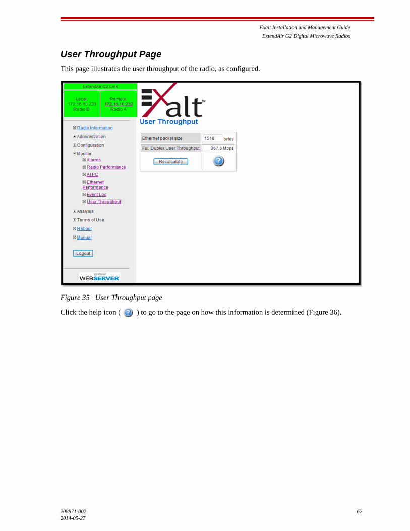
Exalt Installation and Management Guide
ExtendAir G2 Digital Microwave Radios
208871-002 622014-05-27
User Throughput Page
This page illustrates the user throughput of the radio, as configured.
Figure 35 User Throughput page
Click the help icon ( ) to go to the page on how this information is determined (Figure 36).

Exalt Installation and Management Guide
ExtendAir G2 Digital Microwave Radios
63 208871-002
2014-05-27
.
Figure 36 User Throughput Help page
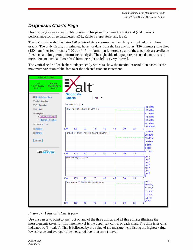
Exalt Installation and Management Guide
ExtendAir G2 Digital Microwave Radios
208871-002 642014-05-27
Diagnostic Charts Page
Use this page as an aid in troubleshooting. This page illustrates the historical (and current) performance for three parameters: RSL, Radio Temperature, and BER.
The horizontal scale illustrates 120 points of time measurement and is synchronized on all three graphs. The scale displays in minutes, hours, or days from the last two hours (120 minutes), five days (120 hours), or four months (120 days). All information is stored, so all of these periods are available for short- and long-term performance analysis. The right side of a graph represents the most recent measurement, and data ‘marches’ from the right-to-left at every interval.
The vertical scale of each chart independently scales to show the maximum resolution based on the maximum variation of the data over the selected time measurement.
Figure 37 Diagnostic Charts page
Use the cursor to point to any spot on any of the three charts, and all three charts illustrate the measurements taken for that time interval in the upper-left corner of each chart. The time interval is indicated by T=(value). This is followed by the value of the measurement, listing the highest value, lowest value and average value measured over that time interval.

Exalt Installation and Management Guide
ExtendAir G2 Digital Microwave Radios
65 208871-002
2014-05-27
For example, if the displayed time interval is minutes, and the cursor is held at the T=17 mark on the horizontal axis, the measurements shown indicate performance from 17 minutes ago. The high/low/average values shown on each chart are measurements made across that specific one-minute interval.
The Far-End Transmit Power chart displays when any combination of ATPC or Receiver Overload Protection is enabled (see ATPC Configuration Page). This chart shows the far-end transmitter changes that are occurring relative to the provided RSL information. Since the far-end transmit power can change on links using ATPC or Receiver Overload Protection, this information is very useful for troubleshooting.
Changes in RSL often have an impact on BER, and this can be confirmed by looking for synchronized events. When BER events occur without corresponding changes in RSL, this normally indicates interference, atmospheric changes, transmission system issues (such as problems with cables, connectors, or antennas), or possibly radio hardware problems.

Exalt Installation and Management Guide
ExtendAir G2 Digital Microwave Radios
208871-002 662014-05-27
Ethernet Utilization Page
This page shows a chart for each Ethernet interface to illustrate inbound and outbound packet utilization. This is shown as a percentage of the interface configuration (that is, if your interface is set for 100BaseT, then 100% represents 100Mbps. Compare offered load (inbound) to delivered load (outbound) to determine if radio capacity is a bottleneck for the data transfer. This chart can illustrate inbound and/or outbound utilization, and uses different colors for data entry. The legend can be hidden.
Figure 38 Ethernet Utilization page
Note that outbound utilization never exceeds the rate where a radio is configured. For example, if the radio is configured for a 55 Mbps capacity, outbound utilization will never exceed 55 Mbps at 100BaseT.
The Ethernet Utilization Watermark level function allows administrators to receive an SNMP trap when watermark conditions are exceeded. For example, if a radio is configured for 55 Mbps capacity, the administrator may wish to be warned if the radio exceeds 50 Mbps for more than 1 hour per day. In this case, set the Watermark level to 50% and the trap duration to 60 minutes. Traps must be enabled to activate this function.
When the watermark level function is enabled, a line on the chart appears for data comparison to the watermark.

Exalt Installation and Management Guide
ExtendAir G2 Digital Microwave Radios
67 208871-002
2014-05-27
Reboot Page
Use this page to reboot the radio. The function may never be required, but can be used in emergencies. All configurations that require a reboot automatically reboot on administrator confirmation.
Figure 39 Reboot page
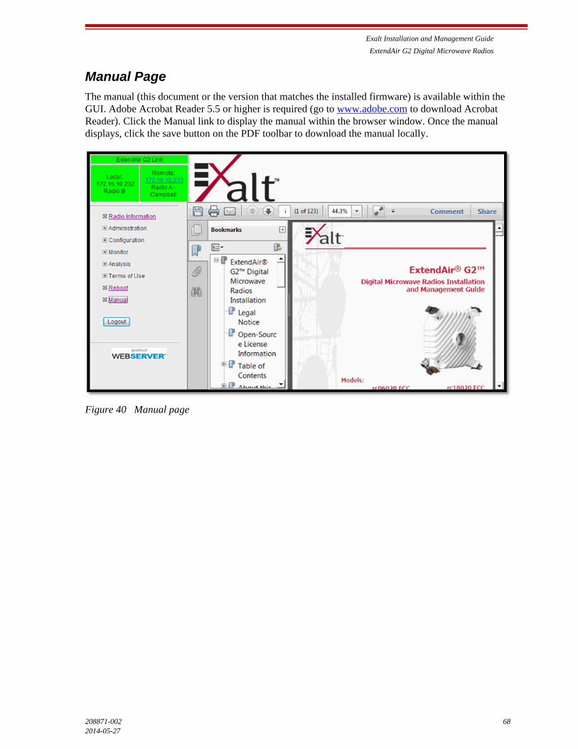
Exalt Installation and Management Guide
ExtendAir G2 Digital Microwave Radios
208871-002 682014-05-27
Manual Page
The manual (this document or the version that matches the installed firmware) is available within the GUI. Adobe Acrobat Reader 5.5 or higher is required (go to www.adobe.com to download Acrobat Reader). Click the Manual link to display the manual within the browser window. Once the manual displays, click the save button on the PDF toolbar to download the manual locally.
Figure 40 Manual page
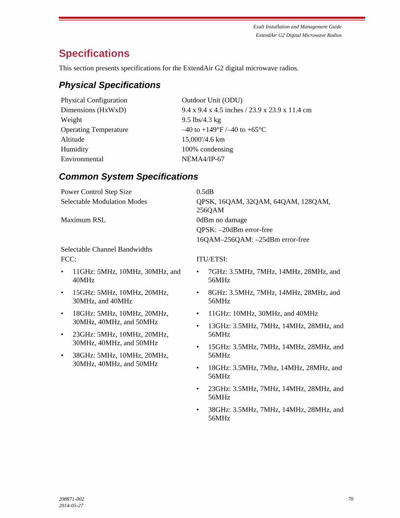
Exalt Installation and Management Guide
ExtendAir G2 Digital Microwave Radios
208871-002 702014-05-27
SpecificationsThis section presents specifications for the ExtendAir G2 digital microwave radios.
Physical Specifications
Common System Specifications
Physical Configuration Outdoor Unit (ODU)Dimensions (HxWxD) 9.4 x 9.4 x 4.5 inches / 23.9 x 23.9 x 11.4 cmWeight 9.5 lbs/4.3 kgOperating Temperature –40 to +149°F /–40 to +65°CAltitude 15,000'/4.6 km Humidity 100% condensingEnvironmental NEMA4/IP-67
Power Control Step Size 0.5dBSelectable Modulation Modes QPSK, 16QAM, 32QAM, 64QAM, 128QAM,
256QAMMaximum RSL 0dBm no damage
QPSK: –20dBm error-free16QAM–256QAM: –25dBm error-free
Selectable Channel BandwidthsFCC:
• 11GHz: 5MHz, 10MHz, 30MHz, and 40MHz
• 15GHz: 5MHz, 10MHz, 20MHz, 30MHz, and 40MHz
• 18GHz: 5MHz, 10MHz, 20MHz, 30MHz, 40MHz, and 50MHz
• 23GHz: 5MHz, 10MHz, 20MHz, 30MHz, 40MHz, and 50MHz
• 38GHz: 5MHz, 10MHz, 20MHz, 30MHz, 40MHz, and 50MHz
ITU/ETSI:
• 7GHz: 3.5MHz, 7MHz, 14MHz, 28MHz, and 56MHz
• 8GHz: 3.5MHz, 7MHz, 14MHz, 28MHz, and 56MHz
• 11GHz: 10MHz, 30MHz, and 40MHz
• 13GHz: 3.5MHz, 7MHz, 14MHz, 28MHz, and 56MHz
• 15GHz: 3.5MHz, 7MHz, 14MHz, 28MHz, and 56MHz
• 18GHz: 3.5MHz, 7Mhz, 14MHz, 28MHz, and 56MHz
• 23GHz: 3.5MHz, 7MHz, 14MHz, 28MHz, and 56MHz
• 38GHz: 3.5MHz, 7MHz, 14MHz, 28MHz, and 56MHz
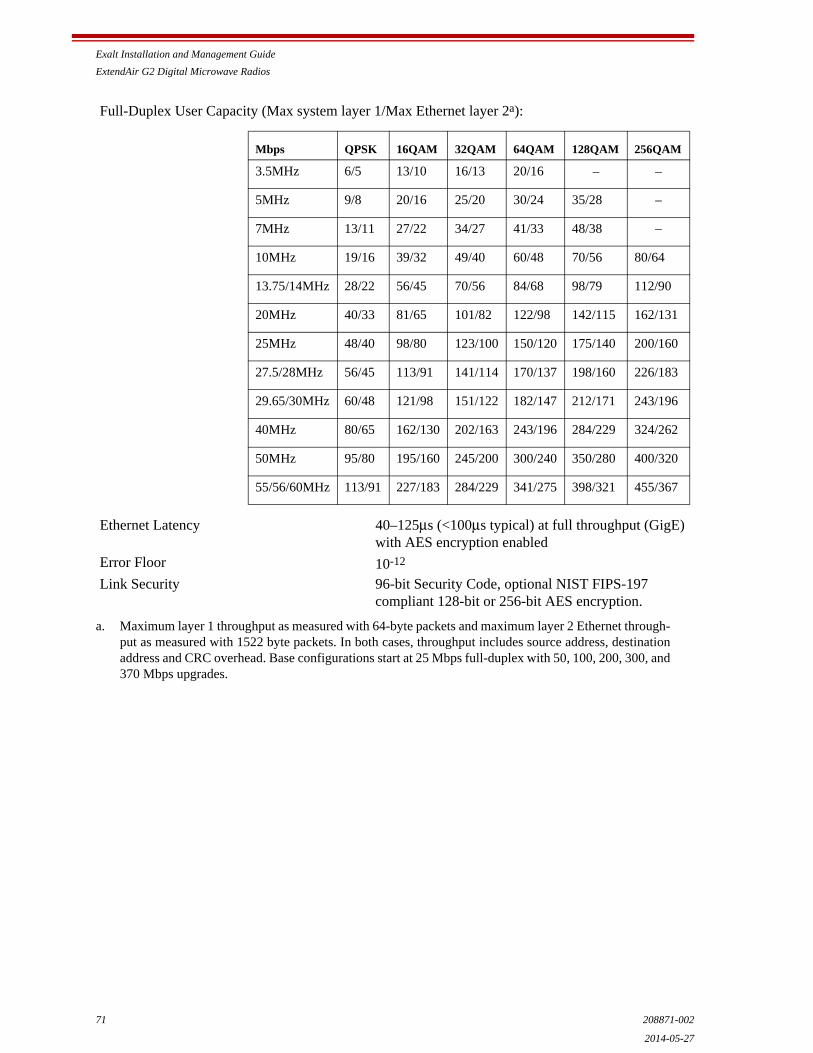
Exalt Installation and Management Guide
ExtendAir G2 Digital Microwave Radios
71 208871-002
2014-05-27
Full-Duplex User Capacity (Max system layer 1/Max Ethernet layer 2a):
Ethernet Latency 40–125μs (<100μs typical) at full throughput (GigE) with AES encryption enabled
Error Floor 10-12
Link Security 96-bit Security Code, optional NIST FIPS-197 compliant 128-bit or 256-bit AES encryption.
a. Maximum layer 1 throughput as measured with 64-byte packets and maximum layer 2 Ethernet through-put as measured with 1522 byte packets. In both cases, throughput includes source address, destinationaddress and CRC overhead. Base configurations start at 25 Mbps full-duplex with 50, 100, 200, 300, and370 Mbps upgrades.
Mbps QPSK 16QAM 32QAM 64QAM 128QAM 256QAM
3.5MHz 6/5 13/10 16/13 20/16 – –
5MHz 9/8 20/16 25/20 30/24 35/28 –
7MHz 13/11 27/22 34/27 41/33 48/38 –
10MHz 19/16 39/32 49/40 60/48 70/56 80/64
13.75/14MHz 28/22 56/45 70/56 84/68 98/79 112/90
20MHz 40/33 81/65 101/82 122/98 142/115 162/131
25MHz 48/40 98/80 123/100 150/120 175/140 200/160
27.5/28MHz 56/45 113/91 141/114 170/137 198/160 226/183
29.65/30MHz 60/48 121/98 151/122 182/147 212/171 243/196
40MHz 80/65 162/130 202/163 243/196 284/229 324/262
50MHz 95/80 195/160 245/200 300/240 350/280 400/320
55/56/60MHz 113/91 227/183 284/229 341/275 398/321 455/367
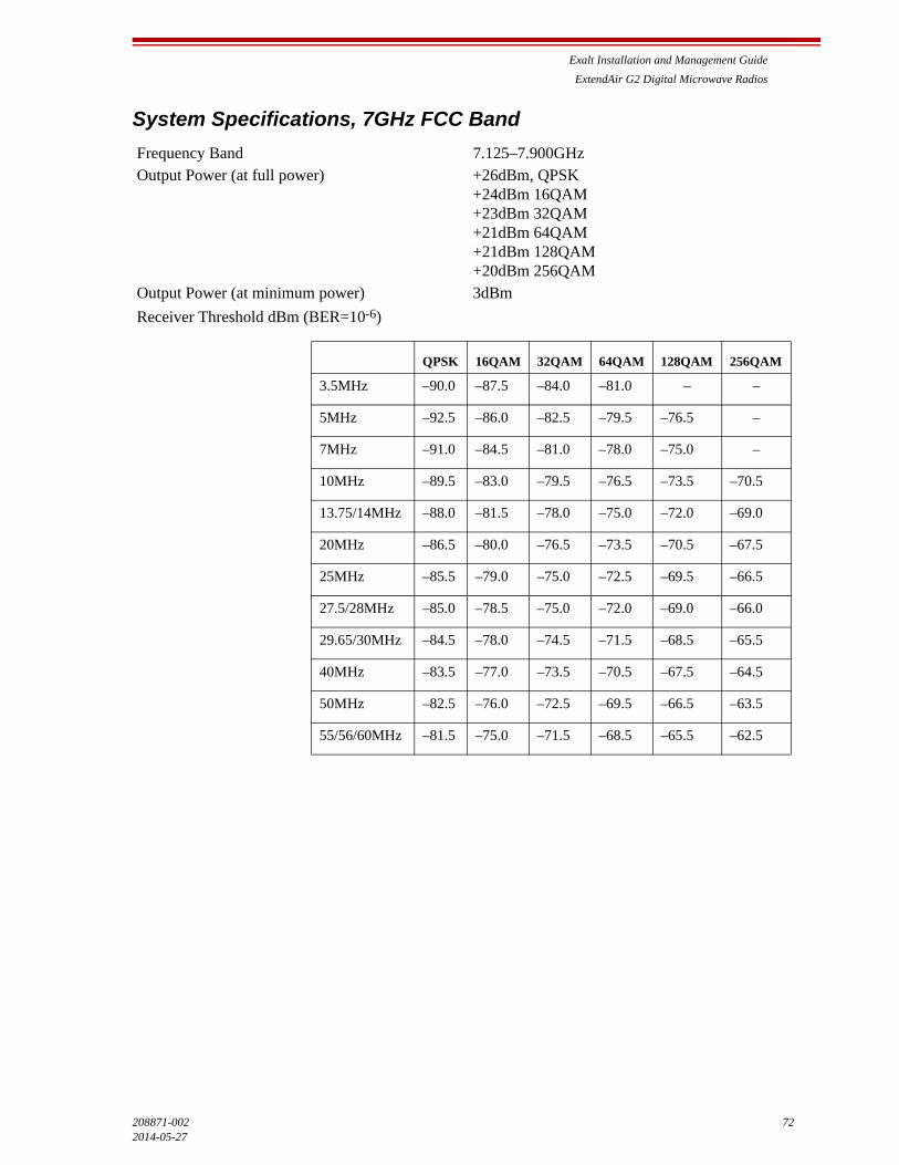
Exalt Installation and Management Guide
ExtendAir G2 Digital Microwave Radios
208871-002 722014-05-27
System Specifications, 7GHz FCC Band
Frequency Band 7.125–7.900GHzOutput Power (at full power) +26dBm, QPSK
+24dBm 16QAM+23dBm 32QAM+21dBm 64QAM+21dBm 128QAM+20dBm 256QAM
Output Power (at minimum power) 3dBm
Receiver Threshold dBm (BER=10-6)
QPSK 16QAM 32QAM 64QAM 128QAM 256QAM
3.5MHz –90.0 –87.5 –84.0 –81.0 – –
5MHz –92.5 –86.0 –82.5 –79.5 –76.5 –
7MHz –91.0 –84.5 –81.0 –78.0 –75.0 –
10MHz –89.5 –83.0 –79.5 –76.5 –73.5 –70.5
13.75/14MHz –88.0 –81.5 –78.0 –75.0 –72.0 –69.0
20MHz –86.5 –80.0 –76.5 –73.5 –70.5 –67.5
25MHz –85.5 –79.0 –75.0 –72.5 –69.5 –66.5
27.5/28MHz –85.0 –78.5 –75.0 –72.0 –69.0 –66.0
29.65/30MHz –84.5 –78.0 –74.5 –71.5 –68.5 –65.5
40MHz –83.5 –77.0 –73.5 –70.5 –67.5 –64.5
50MHz –82.5 –76.0 –72.5 –69.5 –66.5 –63.5
55/56/60MHz –81.5 –75.0 –71.5 –68.5 –65.5 –62.5

Exalt Installation and Management Guide
ExtendAir G2 Digital Microwave Radios
73 208871-002
2014-05-27
RF Diplexers
TR 154MHz Lo/Hi TR 161MHz Lo/Hi
Band 1: 7.428–7.484/7.582–7.638 GHz
Band 2: 7.470–7.526/7.624–7.680 GHz
Band 3: 7.512–7.568/7.666–7.722 GHz
Band 1: 7.114–7.177/7.275–7.338 GHz
Band 2: 7.149–7.212/7.310–7.373 GHz
Band 3: 7.184–7.247/7.345–7.408 GHz
Band 4: 7.219–7.282/7.380–7.443 GHz
Band 5: 7.239–7.302/7.400–7.463 GHz
Band 6: 7.274–7.337/7.435–7.498 GHz
Band 7: 7.309–7.372/7.470–7.533 GHz
Band 8: 7.344–7.407/7.505–7.568 GHz
Band 9: 7.414–7.477/7.575–7.638 GHz
Band 10: 7.449–7.512/7.610–7.679 GHz
Band 11: 7.484–7.547/7.645–7.708 GHz
Band 12: 7.519–7.582/ 7.680–7.744 GHz
Band 13: 7.539–7.602/7.700–7.763 GHz
Band 14: 7.574–7.637/7.735–7.798 GHz
Band 15: 7.609–7.672/7.770–7.833 GHz
Band 16: 7.644–7.707/7.805–7.868 GHz
TR 168MHz Lo/Hi TR 196MHz Lo/Hi
Band 1: 7.443–7.499/7.611–7.667 GHz
Band 2: 7.485–7.541/7.653–7.709 GHz
Band 3: 7.527–7.583/7.695–7.751 GHz
Band 1: 7.093–7.149/7.289–7.345 GHz
Band 2: 7.121–7.177/7.317–7.373 GHz
Band 3: 7.149–7.205/7.345–7.401 GHz
Band 4: 7.177–7.233/7.373–7.429 GHz
Band 5: 7.205–7.261/7.401–7.457 GHz
TR 245MHz Lo/Hi
Band 1: 7.400–7.484/7.645–7.729s GHz
Band 2: 7.484–7.568/7.729–7.813 GHz
Band 3: 7.568–7.652/7.813–7.897 GHz

Exalt Installation and Management Guide
ExtendAir G2 Digital Microwave Radios
208871-002 742014-05-27
System Specifications, 8GHz FCC Band
RF Diplexers
Frequency Band 7.900–8.500GHzOutput Power (at full power) +26dBm, QPSK
+24dBm 16QAM+23dBm 32QAM+21dBm 64QAM+21dBm 128QAM+20dBm 256QAM
Output Power (at minimum power) 3dBm
Receiver Threshold dBm (BER=10-6)
TR119/126MHz Lo/Hi TR 266MHz Lo/Hi
Band 1: 8.279–8.314/8.398–8.433 GHz
Band 2: 8.293–8.328/8.412–8.447 GHz
Band 3: 8.307–8.342/8.426–8.461 GHz
Band 4: 8.321–8.356/8.440–8.475 GHz
Band 5: 8.335–8.370/8.454–8.489 GHz
Band 6: 8.349–8.384/8.468–8.503 GHz
Band 1: 7.905–8.024/8.171–8.290 GHz
Band 2: 8.017–8.136/8.283–8.402 GHz
TR 311.32MHz Lo/Hi
Band 1: 7.731–7.867/8.042–8.178 GHz
Band 2: 7.835–7.971/8.146–8.282 GHz
QPSK 16QAM 32QAM 64QAM 128QAM 256QAM
3.5MHz –94.0 –87.5 –84.0 –81.0 – –
5MHz –92.5 –86.0 –82.5 –79.5 –76.5 –
7MHz –91.0 –84.5 –81.0 –78.0 –75.0 –
10MHz –89.5 –83.0 –79.5 –76.5 –73.5 –70.5
13.75/14MHz –88.0 –81.5 –78.0 –75.0 –72.0 –69.0
20MHz –86.5 –80.0 –76.5 –73.5 –70.5 –67.5
25MHz –85.5 –79.0 –75.0 –72.5 –69.5 –66.5
27.5/28MHz –85.0 –78.5 –75.0 –72.0 –69.0 –66.0
29.65/30MHz –84.5 –78.0 –74.5 –71.5 –68.5 –65.5
40MHz –83.5 –77.0 –73.5 –70.5 –67.5 –64.5
50MHz –82.5 –76.0 –72.5 –69.5 –66.5 –63.5
55/56/60MHz –81.5 –75.0 –71.5 –68.5 –65.5 –62.5
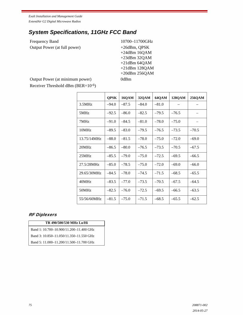
Exalt Installation and Management Guide
ExtendAir G2 Digital Microwave Radios
75 208871-002
2014-05-27
System Specifications, 11GHz FCC Band
RF Diplexers
Frequency Band 10700–11700GHzOutput Power (at full power) +26dBm, QPSK
+24dBm 16QAM+23dBm 32QAM+21dBm 64QAM+21dBm 128QAM+20dBm 256QAM
Output Power (at minimum power) 0dBm
Receiver Threshold dBm (BER=10-6)
TR 490/500/530 MHz Lo/Hi
Band 1: 10.700–10.900/11.200–11.400 GHz
Band 3: 10.850–11.050/11.350–11.550 GHz
Band 5: 11.000–11.200/11.500–11.700 GHz
QPSK 16QAM 32QAM 64QAM 128QAM 256QAM
3.5MHz –94.0 –87.5 –84.0 –81.0 – –
5MHz –92.5 –86.0 –82.5 –79.5 –76.5 –
7MHz –91.0 –84.5 –81.0 –78.0 –75.0 –
10MHz –89.5 –83.0 –79.5 –76.5 –73.5 –70.5
13.75/14MHz –88.0 –81.5 –78.0 –75.0 –72.0 –69.0
20MHz –86.5 –80.0 –76.5 –73.5 –70.5 –67.5
25MHz –85.5 –79.0 –75.0 –72.5 –69.5 –66.5
27.5/28MHz –85.0 –78.5 –75.0 –72.0 –69.0 –66.0
29.65/30MHz –84.5 –78.0 –74.5 –71.5 –68.5 –65.5
40MHz –83.5 –77.0 –73.5 –70.5 –67.5 –64.5
50MHz –82.5 –76.0 –72.5 –69.5 –66.5 –63.5
55/56/60MHz –81.5 –75.0 –71.5 –68.5 –65.5 –62.5

Exalt Installation and Management Guide
ExtendAir G2 Digital Microwave Radios
208871-002 762014-05-27
System Specifications, 13GHz FCC Band
RF Diplexers
Frequency Band 12.750–13.250GHzOutput Power (at full power) +26dBm, QPSK
+24dBm 16QAM+23dBm 32QAM+21dBm 64QAM+21dBm 128QAM+20dBm 256QAM
Output Power (at minimum power) 0dBm
Receiver Threshold dBm (BER=10-6)
TR 266 MHz Lo/Hi
Band 1: 12.751–12.814/13.017–13.080 GHz
Band 2: 12.807–12.870/13.073–13.136 GHz
Band 3: 12.863–12.926/13.129–13.192 GHz
Band 4: 12.919–12.982/13.185–13.248 GHz
QPSK 16QAM 32QAM 64QAM 128QAM 256QAM
3.5MHz –93.5 –87.0 –83.5 –80.5 – –
5MHz –92.0 –85.5 –82.0 –79.0 –76.0 –
7MHz –90.5 –84.0 –80.5 –77.5 –74.5 –
10MHz –89.0 –82.5 –79.0 –76.0 –73.0 –70.0
13.75/14MHz –87.5 –81.0 –77.5 –74.5 –71.5 –68.5
20MHz –86.0 –79.5 –76.0 –73.0 –70.0 –67.0
25MHz –85.0 –78.5 –75.0 –72.0 –69.0 –66.0
27.5/28MHz –84.5 –78.0 –74.5 –71.5 –68.5 –65.5
29.65/30MHz –84.0 –77.5 –74.0 –71.0 –68.0 –65.0
40MHz –83.0 –76.5 –73.0 –70.0 –67.0 –64.0
50MHz –82.0 –75.5 –72.0 –69.0 –66.0 –63.0
55/56/60MHz –81.0 –74.5 –71.0 –68.0 –65.0 –62.0

Exalt Installation and Management Guide
ExtendAir G2 Digital Microwave Radios
77 208871-002
2014-05-27
System Specifications, 15GHz FCC Band
Frequency Band 14.400–15.350GHzOutput Power (at full power) +26dBm, QPSK
+24dBm 16QAM+23dBm 32QAM+21dBm 64QAM+21dBm 128QAM+20dBm 256QAM
Output Power (at minimum power) 0dBm
Receiver Threshold dBm (BER=10-6)
QPSK 16QAM 32QAM 64QAM 128QAM 256QAM
3.5MHz –93.5 –87.0 –83.5 –80.5 – –
5MHz –92.0 –85.5 –82.0 –79.0 –76.0 –
7MHz –90.5 –84.0 –80.5 –77.5 –74.5 –
10MHz –89.0 –82.5 –79.0 –76.0 –73.0 –70.0
13.75/14MHz –87.5 –81.0 –77.5 –74.5 –71.5 –68.5
20MHz –86.0 –79.5 –76.0 –73.0 –70.0 –67.0
25MHz –85.0 –78.5 –75.0 –72.0 –69.0 –66.0
27.5/28MHz –84.5 –78.0 –74.5 –71.5 –68.5 –65.5
29.65/30MHz –84.0 –77.5 –74.0 –71.0 –68.0 –65.0
40MHz –83.0 –76.5 –73.0 –70.0 –67.0 –64.0
50MHz –82.0 –75.5 –72.0 –69.0 –66.0 –63.0
55/56/60MHz –81.0 –74.5 –71.0 –68.0 –65.0 –62.0

Exalt Installation and Management Guide
ExtendAir G2 Digital Microwave Radios
208871-002 782014-05-27
RF Diplexers
TR 315 MHz Lo/Hi TR 490 MHz Lo/Hi
Band 1: 14.627–14.732/14.942–15.047 GHz
Band 2: 14.725–14.844/15.040–15.159 GHz
Band 3: 14.823–14.928/15.138–15.243 GHz
Band 1: 14.403–14.522/14.893–15.012 GHz
Band 2: 14.515–14.634/15.005–15.124 GHz
Band 3: 14.627–14.746/15.117–15.236 GHz
Band 4: 14.739–14.858/15.229–15.348 GHz
TR 420 MHz Lo/Hi TR 728 MHz Lo/Hi
Band 1: 14.501–14.613/14.921–15.033 GHz
Band 2: 14.606–14.725/15.026–15.145 GHz
Band 3: 14.718–14.837/15.138–15.257 GHz
Band 4: 14.816–14.928/15.236–15.348 GHz
Band 1: 14.500–14.620/15.230–15.340 GHz
TR 475 MHz Lo/Hi
Band 1: 14.500–14.668 GHz/14.975–15.143 GHz
Band 2: 14.660–14.828 GHz/15.135–15.303 GHz
Band 3: 14.175–14.883 GHz/15.190–15.358 GHz
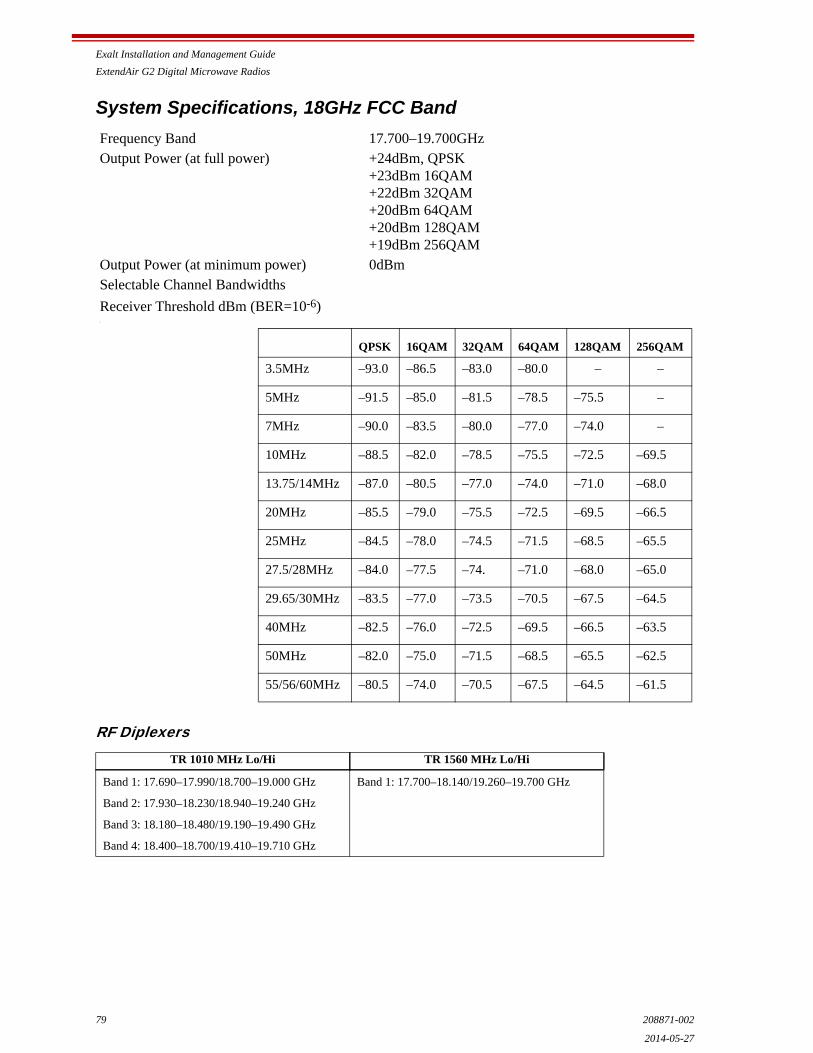
Exalt Installation and Management Guide
ExtendAir G2 Digital Microwave Radios
79 208871-002
2014-05-27
System Specifications, 18GHz FCC Band
RF Diplexers
Frequency Band 17.700–19.700GHzOutput Power (at full power) +24dBm, QPSK
+23dBm 16QAM+22dBm 32QAM+20dBm 64QAM+20dBm 128QAM+19dBm 256QAM
Output Power (at minimum power) 0dBmSelectable Channel Bandwidths
Receiver Threshold dBm (BER=10-6)\
TR 1010 MHz Lo/Hi TR 1560 MHz Lo/Hi
Band 1: 17.690–17.990/18.700–19.000 GHz
Band 2: 17.930–18.230/18.940–19.240 GHz
Band 3: 18.180–18.480/19.190–19.490 GHz
Band 4: 18.400–18.700/19.410–19.710 GHz
Band 1: 17.700–18.140/19.260–19.700 GHz
QPSK 16QAM 32QAM 64QAM 128QAM 256QAM
3.5MHz –93.0 –86.5 –83.0 –80.0 – –
5MHz –91.5 –85.0 –81.5 –78.5 –75.5 –
7MHz –90.0 –83.5 –80.0 –77.0 –74.0 –
10MHz –88.5 –82.0 –78.5 –75.5 –72.5 –69.5
13.75/14MHz –87.0 –80.5 –77.0 –74.0 –71.0 –68.0
20MHz –85.5 –79.0 –75.5 –72.5 –69.5 –66.5
25MHz –84.5 –78.0 –74.5 –71.5 –68.5 –65.5
27.5/28MHz –84.0 –77.5 –74. –71.0 –68.0 –65.0
29.65/30MHz –83.5 –77.0 –73.5 –70.5 –67.5 –64.5
40MHz –82.5 –76.0 –72.5 –69.5 –66.5 –63.5
50MHz –82.0 –75.0 –71.5 –68.5 –65.5 –62.5
55/56/60MHz –80.5 –74.0 –70.5 –67.5 –64.5 –61.5
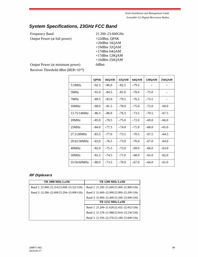
Exalt Installation and Management Guide
ExtendAir G2 Digital Microwave Radios
208871-002 802014-05-27
System Specifications, 23GHz FCC Band
RF Diplexers
Frequency Band 21.200–23.600GHzOutput Power (at full power) +22dBm, QPSK
+20dBm 16QAM+19dBm 32QAM+17dBm 64QAM+17dBm 128QAM+16dBm 256QAM
Output Power (at minimum power) 0dBm
Receiver Threshold dBm (BER=10-6)\
TR 1008 MHz Lo/Hi TR 1200 MHz Lo/Hi
Band 1: 22.000–22.314/23.008–23.322 GHz
Band 2: 22.286–22.600/23.294–23.608 GHz
Band 1: 21.200–21.600/22.400–22.800 GHz
Band 2: 21.600–22.000/22.800–23.200 GHz
Band 3: 22.000–22.400/23.200–23.600 GHz
TR 1232 MHz Lo/Hi
Band 1: 21.200–21.620/22.432–22.852 GHz
Band 2: 21.578–21.988/22.810–23.230 GHz
Band 3: 21.956–22.376/23.188–23.608 GHz
QPSK 16QAM 32QAM 64QAM 128QAM 256QAM
3.5MHz –92.5 –86.0 –82.5 –79.5 – –
5MHz –91.0 –84.5 –81.0 –78.0 –75.0 –
7MHz –89.5 –83.0 –79.5 –76.5 –73.5 –
10MHz –88.0 –81.5 –78.0 –75.0 –72.0 –69.0
13.75/14MHz –86.5 –80.0 –76.5 –73.5 –70.5 –67.5
20MHz –85.0 –78.5 –75.0 –72.0 –69.0 –66.0
25MHz –84.0 –77.5 –74.0 –71.0 –68.0 –65.0
27.5/28MHz –83.5 –77.0 –73.5 –70.5 –67.5 –64.5
29.65/30MHz –83.0 –76.5 –73.0 –70.0 –67.0 –64.0
40MHz –82.0 –75.5 –72.0 –69.0 –66.0 –63.0
50MHz –81.5 –74.5 –71.0 –68.0 –65.0 –62.0
55/56/60MHz –80.0 –73.5 –70.0 –67.0 –64.0 –61.0

Exalt Installation and Management Guide
ExtendAir G2 Digital Microwave Radios
81 208871-002
2014-05-27
System Specifications, 38GHz FCC Band
RF Diplexers
Frequency Band 37.000–40.000GHzOutput Power (at full power) +21dBm, QPSK
+19dBm 16QAM+18dBm 32QAM+16dBm 64QAM+16dBm 128QAM+15dBm 256QAM
Output Power (at minimum power) 0dBmSelectable Channel Bandwidths
Receiver Threshold dBm (BER=10-6)\
TR 700 MHz Lo/Hi TR 1260 MHz Lo/Hi
Band 1: 38.595–38.805/39.295–39.505 GHz
Band 2: 38.795–39.005/39.495–39.705 GHz
Band 3: 38.995–39.205/39.695–39.905 GHz
Band 4: 39.195–39.405/39.895–40.105 GHz
Band 1: 37.044–37.632/38.304–38.892 GHz
Band 2: 37.604–38.192/38.864–39.452 GHz
QPSK 16QAM 32QAM 64QAM 128QAM 256QAM
3.5MHz –90.0 –83.5 –80.0 –77.0 – –
5MHz –88.5 –82.0 –78.5 –75.5 –72.5 –
7MHz –87.0 –80.5 –77.0 –74.0 –71.0 –
10MHz –85.5 –79.0 –75.5 –72.5 –69.5 –66.5
13.75/14MHz –84.0 –77.5 –74.0 –71.0 –68.0 –65.0
20MHz –82.5 –76.0 –72.5 –69.5 –66.5 –63.5
25MHz –81.5 –75.0 –71.5 –68.5 –65.5 –62.5
27.5/28MHz –81.0 –74.5 –71.0 –68.0 –65.0 –62.0
29.65/30MHz –80.5 –74.0 –70.5 –67.5 –64.5 –61.5
40MHz –79.5 –73.0 –69.5 –66.5 –63.5 –60.5
50MHz –78.5 –72.0 –68.5 –65.5 –62.5 –59.5
55/56/60MHz –77.5 –71.0 –67.5 –64.5 –61.5 –58.5
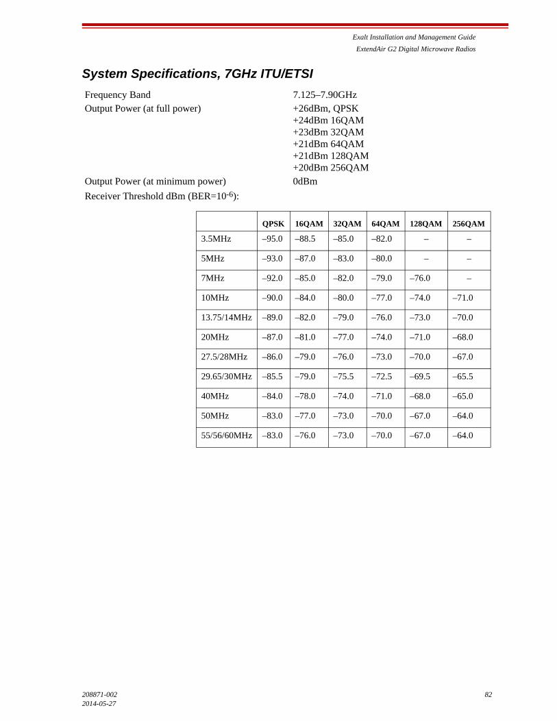
Exalt Installation and Management Guide
ExtendAir G2 Digital Microwave Radios
208871-002 822014-05-27
System Specifications, 7GHz ITU/ETSI
Frequency Band 7.125–7.90GHzOutput Power (at full power) +26dBm, QPSK
+24dBm 16QAM+23dBm 32QAM+21dBm 64QAM+21dBm 128QAM+20dBm 256QAM
Output Power (at minimum power) 0dBm
Receiver Threshold dBm (BER=10-6):
QPSK 16QAM 32QAM 64QAM 128QAM 256QAM
3.5MHz –95.0 –88.5 –85.0 –82.0 – –
5MHz –93.0 –87.0 –83.0 –80.0 – –
7MHz –92.0 –85.0 –82.0 –79.0 –76.0 –
10MHz –90.0 –84.0 –80.0 –77.0 –74.0 –71.0
13.75/14MHz –89.0 –82.0 –79.0 –76.0 –73.0 –70.0
20MHz –87.0 –81.0 –77.0 –74.0 –71.0 –68.0
27.5/28MHz –86.0 –79.0 –76.0 –73.0 –70.0 –67.0
29.65/30MHz –85.5 –79.0 –75.5 –72.5 –69.5 –65.5
40MHz –84.0 –78.0 –74.0 –71.0 –68.0 –65.0
50MHz –83.0 –77.0 –73.0 –70.0 –67.0 –64.0
55/56/60MHz –83.0 –76.0 –73.0 –70.0 –67.0 –64.0

Exalt Installation and Management Guide
ExtendAir G2 Digital Microwave Radios
83 208871-002
2014-05-27
RF Diplexers
TR 154 MHz Lo/Hi TR 168 MHz Lo/Hi
Band 1: 7.582–7.638 GHz/7.428–7.484 GHz
Band 2: 7.624–7.680 GHz/7.470–7.526 GHz
Band 3: 7.666–7.722 GHz/7.512–7.568 GHz
Band 1: 7.611–7.667 GHz/7.443–7.499 GHz
Band 2: 7.653–7.709 GHz/7.485–7.541 GHz
Band 3: 7.695–7.751 GHz/7.527–7.583 GHz
TR 161 MHz Lo/Hi TR 196 MHz Lo/Hi
Band 1: 7.275–7.338 GHz/7.114–7.177 GHz
Band 2: 7.310–7.373 GHz/7.149–7.212 GHz
Band 3: 7.345–7.408 GHz/7.184–7.247 GHz
Band 4: 7.380–7.443 GHz/7.219–7.282 GHz
Band 5: 7.400–7.463 GHz/7.239–7.302 GHz
Band 6: 7.435–7.498 GHz/7.274–7.337 GHz
Band 7: 7.470–7.533 GHz/7.309–7.372 GHz
Band 8: 7.505–7.568 GHz/7.344–7.407 GHz
Band 9: 7.575–7.638 GHz/7.414–7.477 GHz
Band 10: 7.610–7.673 GHz/7.449–7.512 GHz
Band 11: 7.645–7.708 GHz/7.484–7.547 GHz
Band 12: 7.680–7.743 GHz/7.519–7.582 GHz
Band 13: 7.700–7.763 GHz/7.539–7.602 GHz
Band 14: 7.735–7.798 GHz/7.574–7.637 GHz
Band 15: 7.770–7.833 GHz/7.609–7.672 GHz
Band 16: 7.805–7.868 GHz/7.644–7.707 GHz
Band 1: 7.289–7.345 GHz/7.093–7.149 GHz
Band 2: 7.317–7.373 GHz/7.121–7.177 GHz
Band 3: 7.345–7.401 GHz/7.149–7.205 GHz
Band 4: 7.373–7.429 GHz/7.177–7.233 GHz
Band 5: 7.205–7.261 GHz/7.401–7.457 GHz
TR 245 MHz Lo/Hi
Band 1: 7.645–7.729 GHz/7.400–7.484 GHz
Band 2: 7.729–7.813 GHz/7.484–7.568 GHz
Band 3: 7.813–7.897 GHz/7.568–7.652 GHz
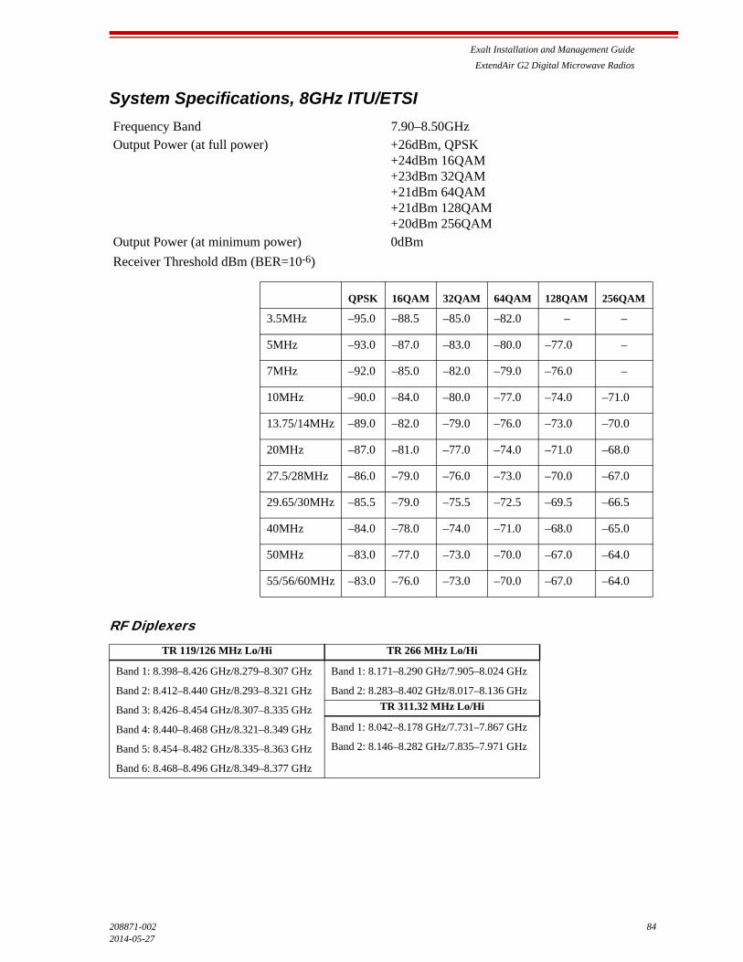
Exalt Installation and Management Guide
ExtendAir G2 Digital Microwave Radios
208871-002 842014-05-27
System Specifications, 8GHz ITU/ETSI
RF Diplexers
Frequency Band 7.90–8.50GHzOutput Power (at full power) +26dBm, QPSK
+24dBm 16QAM+23dBm 32QAM+21dBm 64QAM+21dBm 128QAM+20dBm 256QAM
Output Power (at minimum power) 0dBm
Receiver Threshold dBm (BER=10-6)
TR 119/126 MHz Lo/Hi TR 266 MHz Lo/Hi
Band 1: 8.398–8.426 GHz/8.279–8.307 GHz
Band 2: 8.412–8.440 GHz/8.293–8.321 GHz
Band 3: 8.426–8.454 GHz/8.307–8.335 GHz
Band 4: 8.440–8.468 GHz/8.321–8.349 GHz
Band 5: 8.454–8.482 GHz/8.335–8.363 GHz
Band 6: 8.468–8.496 GHz/8.349–8.377 GHz
Band 1: 8.171–8.290 GHz/7.905–8.024 GHz
Band 2: 8.283–8.402 GHz/8.017–8.136 GHz
TR 311.32 MHz Lo/Hi
Band 1: 8.042–8.178 GHz/7.731–7.867 GHz
Band 2: 8.146–8.282 GHz/7.835–7.971 GHz
QPSK 16QAM 32QAM 64QAM 128QAM 256QAM
3.5MHz –95.0 –88.5 –85.0 –82.0 – –
5MHz –93.0 –87.0 –83.0 –80.0 –77.0 –
7MHz –92.0 –85.0 –82.0 –79.0 –76.0 –
10MHz –90.0 –84.0 –80.0 –77.0 –74.0 –71.0
13.75/14MHz –89.0 –82.0 –79.0 –76.0 –73.0 –70.0
20MHz –87.0 –81.0 –77.0 –74.0 –71.0 –68.0
27.5/28MHz –86.0 –79.0 –76.0 –73.0 –70.0 –67.0
29.65/30MHz –85.5 –79.0 –75.5 –72.5 –69.5 –66.5
40MHz –84.0 –78.0 –74.0 –71.0 –68.0 –65.0
50MHz –83.0 –77.0 –73.0 –70.0 –67.0 –64.0
55/56/60MHz –83.0 –76.0 –73.0 –70.0 –67.0 –64.0

Exalt Installation and Management Guide
ExtendAir G2 Digital Microwave Radios
85 208871-002
2014-05-27
System Specifications, 11GHz ITU/ETSI
RF Diplexers
Frequency Band 10.70–11.70GHzOutput Power (at full power) +26dBm, QPSK
+24dBm 16QAM+23dBm 32QAM+21dBm 64QAM+21dBm 128QAM+20dBm 256QAM
Output Power (at minimum power) 0dBm
Receiver Threshold dBm (BER=10-6)
TR 490/500/530 MHz Lo/Hi
Band 1: 10.695–10.895 GHz/11.195–11.400 GHz
Band 2: 10.850–11.050 GHz/11.350–11.555 GHz
Band 3: 11.000–11.200 GHz/11.500–11.705 GHz
Band 4: 10.925–11.125 GHz/11.425–11.630 GHz
Band 5: 11.000–11.200 GHz/11.500–11.705 GHz
QPSK 16QAM 32QAM 64QAM 128QAM 256QAM
3.5MHz –94.0 –87.5 –84.0 –81.0 – –
5MHz –92.0 –86.0 –82.5 –79.5 –76.5 –
7MHz –91.0 –84.5 –81.0 –78.0 –75.0 –
10MHz –89.0 –83.0 –79.5 –76.5 –73.5 –70.5
13.75/14MHz –88.0 –81.0 –78.0 –75.0 –72.0 –69.0
20MHz –86.0 –80.0 –76.5 –73.5 –70.5 –67.5
27.5/28MHz –85.0 –78.0 –75.0 –72.0 –69.0 –66.0
29.65/30MHz –84.5 –78.0 –74.5 –71.5 –68.5 –65.5
40MHz –83.0 –77.0 –73.5 –70.5 –67.5 –64.5
50MHz –82.0 –76.0 –72.0 –69.0 –66.0 –63.0
55/56/60MHz –82.0 –75.0 –72.0 –69.0 –66.0 –63.0
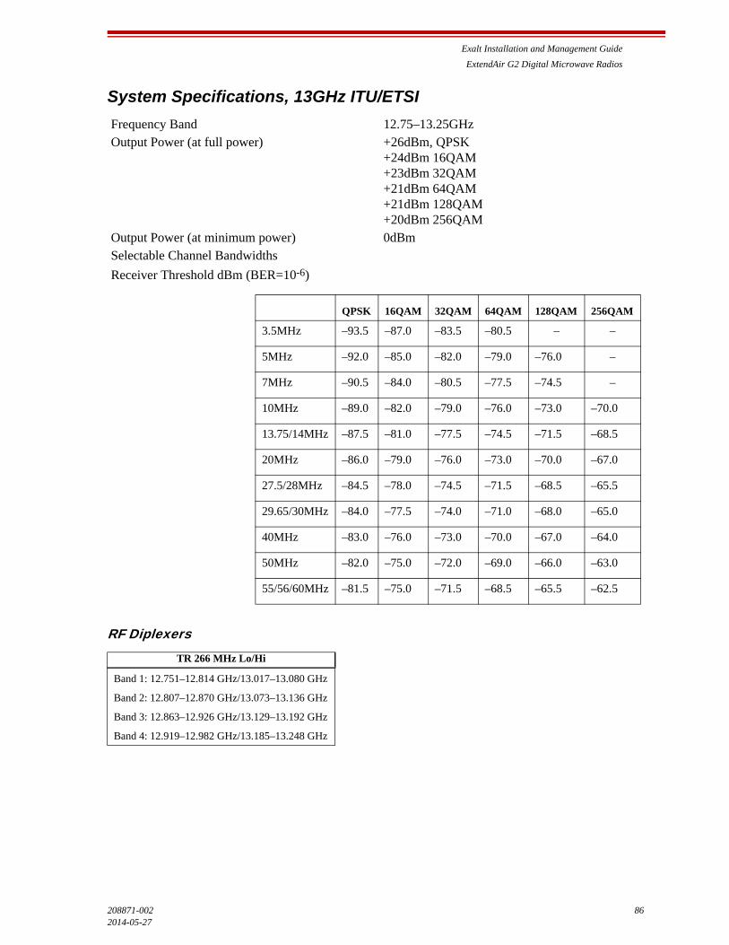
Exalt Installation and Management Guide
ExtendAir G2 Digital Microwave Radios
208871-002 862014-05-27
System Specifications, 13GHz ITU/ETSI
RF Diplexers
Frequency Band 12.75–13.25GHzOutput Power (at full power) +26dBm, QPSK
+24dBm 16QAM+23dBm 32QAM+21dBm 64QAM+21dBm 128QAM+20dBm 256QAM
Output Power (at minimum power) 0dBmSelectable Channel Bandwidths
Receiver Threshold dBm (BER=10-6)
TR 266 MHz Lo/Hi
Band 1: 12.751–12.814 GHz/13.017–13.080 GHz
Band 2: 12.807–12.870 GHz/13.073–13.136 GHz
Band 3: 12.863–12.926 GHz/13.129–13.192 GHz
Band 4: 12.919–12.982 GHz/13.185–13.248 GHz
QPSK 16QAM 32QAM 64QAM 128QAM 256QAM
3.5MHz –93.5 –87.0 –83.5 –80.5 – –
5MHz –92.0 –85.0 –82.0 –79.0 –76.0 –
7MHz –90.5 –84.0 –80.5 –77.5 –74.5 –
10MHz –89.0 –82.0 –79.0 –76.0 –73.0 –70.0
13.75/14MHz –87.5 –81.0 –77.5 –74.5 –71.5 –68.5
20MHz –86.0 –79.0 –76.0 –73.0 –70.0 –67.0
27.5/28MHz –84.5 –78.0 –74.5 –71.5 –68.5 –65.5
29.65/30MHz –84.0 –77.5 –74.0 –71.0 –68.0 –65.0
40MHz –83.0 –76.0 –73.0 –70.0 –67.0 –64.0
50MHz –82.0 –75.0 –72.0 –69.0 –66.0 –63.0
55/56/60MHz –81.5 –75.0 –71.5 –68.5 –65.5 –62.5

Exalt Installation and Management Guide
ExtendAir G2 Digital Microwave Radios
87 208871-002
2014-05-27
System Specifications, 15GHz ITU/ETSI
RF Diplexers
Frequency Band 14.400–15.350GHzOutput Power (at full power) +26dBm, QPSK
+24dBm 16QAM+23dBm 32QAM+21dBm 64QAM+21dBm 128QAM+20dBm 256QAM
Output Power (at minimum power) 0dBm
Receiver Threshold dBm (BER=10-6)
TR 315 MHz Lo/Hi TR 490 MHz Lo/Hi
Band 1: 14.627–14.746 GHz/14.942–15.061 GHz
Band 2: 14.725–14.844 GHz/15.040–15.159 GHz
Band 3: 14.823–14.942 GHz/15.138–15.257 GHz
Band 1: 14.403–14.522 GHz/14.893–15.012 GHz
Band 2: 14.515–14.634 GHz/15.005–15.124 GHz
Band 3: 14.627–14.746 GHz/15.117–15.236 GHz
Band 4: 14.739–14.858 GHz/15.229–15.348 GHz
TR 420 MHz Lo/Hi TR 728 MHz Lo/Hi
Band 1: 14.501–14.613 GHz/14.921–15.033 GHz
Band 2: 14.606–14.725 GHz/15.026–15.145 GHz
Band 3: 14.718–14.837 GHz/15.138–15.257 GHz
Band 4: 14.816–14.928 GHz/15.236–15.348 GHz
Band 1: 14.500–14.615 GHz/15.228–15.343 GHz
QPSK 16QAM 32QAM 64QAM 128QAM 256QAM
3.5MHz –93.5 –87.0 –83.5 –80.5 – –
5MHz –92.0 –85.0 –82.0 –79.0 –76.0 –
7MHz –90.5 –84.0 –80.5 –77.5 –74.5 –
10MHz –89.0 –82.0 –79.0 –76.0 –73.0 –70.0
13.75/14MHz –87.5 –81.0 –77.5 –74.5 –71.5 –68.5
20 MHz –86.0 –79.0 –76.0 –73.0 –70.0 –67.0
27.5/28MHz –84.5 –78.0 –74.5 –71.5 –68.5 –65.5
29.65/30MHz –84.0 –77.5 –74.0 –71.0 –68.0 –65.0
40MHz –83.0 –76.0 –73.0 –70.0 –67.0 –64.0
50MHz –82.0 –75.0 –72.0 –69.0 –66.0 –63.0
55/56/60MHz –81.5 –75.0 –71.5 –68.5 –65.5 –62.5
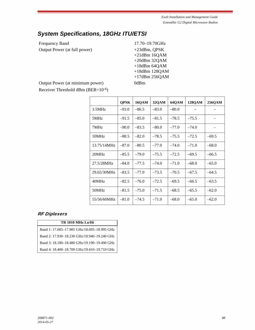
Exalt Installation and Management Guide
ExtendAir G2 Digital Microwave Radios
208871-002 882014-05-27
System Specifications, 18GHz ITU/ETSI
RF Diplexers
Frequency Band 17.70–19.70GHzOutput Power (at full power) +23dBm, QPSK
+21dBm 16QAM+20dBm 32QAM+18dBm 64QAM+18dBm 128QAM+17dBm 256QAM
Output Power (at minimum power) 0dBm
Receiver Threshold dBm (BER=10-6)
TR 1010 MHz Lo/Hi
Band 1: 17.685–17.985 GHz/18.695–18.995 GHz
Band 2: 17.930–18.230 GHz/18.940–19.240 GHz
Band 3: 18.180–18.480 GHz/19.190–19.490 GHz
Band 4: 18.400–18.700 GHz/19.410–19.710 GHz
QPSK 16QAM 32QAM 64QAM 128QAM 256QAM
3.5MHz –93.0 –86.5 –83.0 –80.0 – –
5MHz –91.5 –85.0 –81.5 –78.5 –75.5 –
7MHz –90.0 –83.5 –80.0 –77.0 –74.0 –
10MHz –88.5 –82.0 –78.5 –75.5 –72.5 –69.5
13.75/14MHz –87.0 –80.5 –77.0 –74.0 –71.0 –68.0
20MHz –85.5 –79.0 –75.5 –72.5 –69.5 –66.5
27.5/28MHz –84.0 –77.5 –74.0 –71.0 –68.0 –65.0
29.65/30MHz –83.5 –77.0 –73.5 –70.5 –67.5 –64.5
40MHz –82.5 –76.0 –72.5 –69.5 –66.5 –63.5
50MHz –81.5 –75.0 –71.5 –68.5 –65.5 –62.0
55/56/60MHz –81.0 –74.5 –71.0 –68.0 –65.0 –62.0

Exalt Installation and Management Guide
ExtendAir G2 Digital Microwave Radios
89 208871-002
2014-05-27
System Specifications, 23GHz ITU/ETSI
RF Diplexers
Frequency Band 21.200–23.610GHzOutput Power (at full power) +22dBm, QPSK
+20dBm 16QAM+19dBm 32QAM+17dBm 64QAM+17dBm 128QAM+16dBm 256QAM
Output Power (at minimum power) 0dBm
Receiver Threshold dBm (BER=10-6)
TR 1008 MHz Lo/Hi TR 1232 MHz Lo/Hi
Band 1: 22.000–22.314 GHz/23.008–23.322 GHz
Band 2: 22.286–22.600 GHz/23.294–23.608 GHz
Band 1: 21.200–21.500 GHz/22.432–22.732 GHz
Band 2: 21.472–21.786 GHz/22.704–23.018 GHz
Band 3: 21.779–22.093 GHz/23.011–23.325 GHz
Band 4: 22.086–22.386 GHz/23.318–23.618 GHz
TR 1200 MHz Lo/Hi
Band 1: 21.200–21.600 GHz/22.400–22.800 GHz
Band 2: 21.600–22.000 GHz/22.800–23.200 GHz
Band 3: 22.000–22.400 GHz/23.200–23.600 GHz
QPSK 16QAM 32QAM 64QAM 128QAM 256QAM
3.5MHz –92.5 –86.0 –82.5 –79.5 – –
5MHz –91.0 –84.0 –81.0 –78.0 –75.0 –
7MHz –89.5 –83.0 –79.5 –76.5 –73.5 –
10MHz –88.0 –81.0 –78.0 –75.0 –72.0 –69.0
13.75/14MHz –86.5 –80.0 –76.5 –73.5 –70.5 –67.5
20MHz –85.0 –78.0 –75.0 –72.0 –69.0 –66.0
27.5/28MHz –83.5 –77.0 –73.5 –70.5 –67.5 –64.5
29.65/30MHz –83.0 –76.5 –73.0 –70.0 –67.0 –64.0
40MHz –82.0 –75.0 –72.0 –69.0 –66.0 –63.0
50MHz –81.0 –74.0 –71.0 –68.0 –65.0 –62.0
55/56/60MHz –80.5 –74.0 –70.5 –67.5 –64.5 –61.5
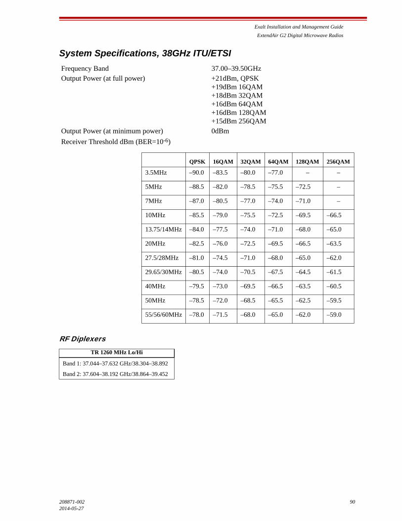
Exalt Installation and Management Guide
ExtendAir G2 Digital Microwave Radios
208871-002 902014-05-27
System Specifications, 38GHz ITU/ETSI
RF Diplexers
Frequency Band 37.00–39.50GHzOutput Power (at full power) +21dBm, QPSK
+19dBm 16QAM+18dBm 32QAM+16dBm 64QAM+16dBm 128QAM+15dBm 256QAM
Output Power (at minimum power) 0dBm
Receiver Threshold dBm (BER=10-6)
TR 1260 MHz Lo/Hi
Band 1: 37.044–37.632 GHz/38.304–38.892
Band 2: 37.604–38.192 GHz/38.864–39.452
QPSK 16QAM 32QAM 64QAM 128QAM 256QAM
3.5MHz –90.0 –83.5 –80.0 –77.0 – –
5MHz –88.5 –82.0 –78.5 –75.5 –72.5 –
7MHz –87.0 –80.5 –77.0 –74.0 –71.0 –
10MHz –85.5 –79.0 –75.5 –72.5 –69.5 –66.5
13.75/14MHz –84.0 –77.5 –74.0 –71.0 –68.0 –65.0
20MHz –82.5 –76.0 –72.5 –69.5 –66.5 –63.5
27.5/28MHz –81.0 –74.5 –71.0 –68.0 –65.0 –62.0
29.65/30MHz –80.5 –74.0 –70.5 –67.5 –64.5 –61.5
40MHz –79.5 –73.0 –69.5 –66.5 –63.5 –60.5
50MHz –78.5 –72.0 –68.5 –65.5 –62.5 –59.5
55/56/60MHz –78.0 –71.5 –68.0 –65.0 –62.0 –59.0

Exalt Installation and Management Guide
ExtendAir G2 Digital Microwave Radios
91 208871-002
2014-05-27
Interfaces
RF
Ethernet
Power
Connector Waveguide flange:
7GHz and 8GHz:WR112/UBR8411GHz and 13GHz: WR75/UBR12015GHz: WR62/UBR14018GHz: WR42/UBR22023GHz: WR42/UBR22038GHz: 0.219" diameter
Impedance 50 Ohms
Connectors RJ-45, female, auto-MDIXInterface Speed 10/100/1000 MbpsDuplex Half, full, auto, selectableCompliance 802.3
Input Voltage 48VDCDC Consumption <40W (0.85A)
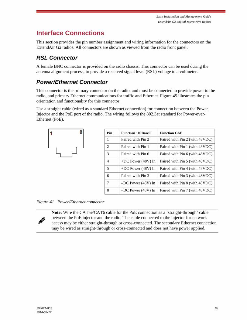
Exalt Installation and Management Guide
ExtendAir G2 Digital Microwave Radios
208871-002 922014-05-27
Interface ConnectionsThis section provides the pin number assignment and wiring information for the connectors on the ExtendAir G2 radios. All connectors are shown as viewed from the radio front panel.
RSL Connector
A female BNC connector is provided on the radio chassis. This connector can be used during the antenna alignment process, to provide a received signal level (RSL) voltage to a voltmeter.
Power/Ethernet Connector
This connector is the primary connector on the radio, and must be connected to provide power to the radio, and primary Ethernet communications for traffic and Ethernet. Figure 45 illustrates the pin orientation and functionality for this connector.
Use a straight cable (wired as a standard Ethernet connection) for connection between the Power Injector and the PoE port of the radio. The wiring follows the 802.3at standard for Power-over-Ethernet (PoE).
Figure 41 Power/Ethernet connector
Note: Wire the CAT5e/CAT6 cable for the PoE connection as a ‘straight-through’ cable between the PoE injector and the radio. The cable connected to the injector for network access may be either straight-through or cross-connected. The secondary Ethernet connection may be wired as straight-through or cross-connected and does not have power applied.
Pin Function 100BaseT Function GbE
1 Paired with Pin 2 Paired with Pin 2 (with 48VDC)
2 Paired with Pin 1 Paired with Pin 1 (with 48VDC)
3 Paired with Pin 6 Paired with Pin 6 (with 48VDC)
4 +DC Power (48V) In Paired with Pin 5 (with 48VDC)
5 +DC Power (48V) In Paired with Pin 4 (with 48VDC)
6 Paired with Pin 3 Paired with Pin 3 (with 48VDC)
7 –DC Power (48V) In Paired with Pin 8 (with 48VDC)
8 –DC Power (48V) In Paired with Pin 7 (with 48VDC)
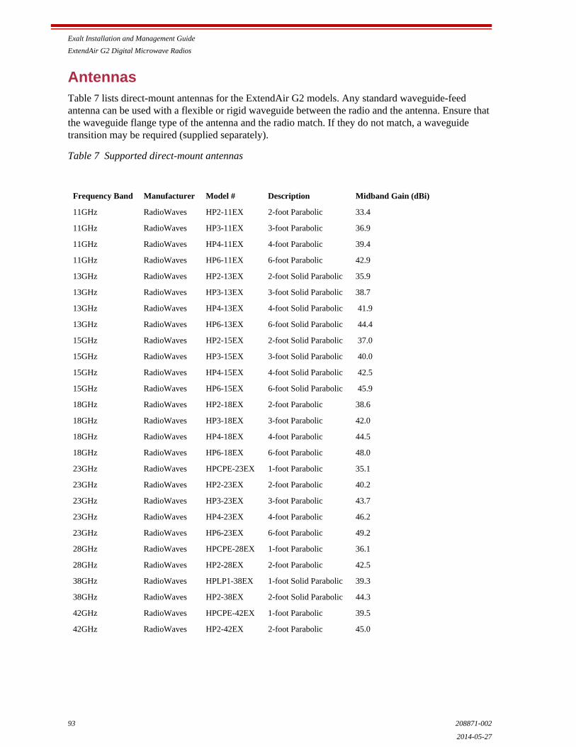
Exalt Installation and Management Guide
ExtendAir G2 Digital Microwave Radios
93 208871-002
2014-05-27
AntennasTable 7 lists direct-mount antennas for the ExtendAir G2 models. Any standard waveguide-feed antenna can be used with a flexible or rigid waveguide between the radio and the antenna. Ensure that the waveguide flange type of the antenna and the radio match. If they do not match, a waveguide transition may be required (supplied separately).
Table 7 Supported direct-mount antennas
Frequency Band Manufacturer Model # Description Midband Gain (dBi)
11GHz RadioWaves HP2-11EX 2-foot Parabolic 33.4
11GHz RadioWaves HP3-11EX 3-foot Parabolic 36.9
11GHz RadioWaves HP4-11EX 4-foot Parabolic 39.4
11GHz RadioWaves HP6-11EX 6-foot Parabolic 42.9
13GHz RadioWaves HP2-13EX 2-foot Solid Parabolic 35.9
13GHz RadioWaves HP3-13EX 3-foot Solid Parabolic 38.7
13GHz RadioWaves HP4-13EX 4-foot Solid Parabolic 41.9
13GHz RadioWaves HP6-13EX 6-foot Solid Parabolic 44.4
15GHz RadioWaves HP2-15EX 2-foot Solid Parabolic 37.0
15GHz RadioWaves HP3-15EX 3-foot Solid Parabolic 40.0
15GHz RadioWaves HP4-15EX 4-foot Solid Parabolic 42.5
15GHz RadioWaves HP6-15EX 6-foot Solid Parabolic 45.9
18GHz RadioWaves HP2-18EX 2-foot Parabolic 38.6
18GHz RadioWaves HP3-18EX 3-foot Parabolic 42.0
18GHz RadioWaves HP4-18EX 4-foot Parabolic 44.5
18GHz RadioWaves HP6-18EX 6-foot Parabolic 48.0
23GHz RadioWaves HPCPE-23EX 1-foot Parabolic 35.1
23GHz RadioWaves HP2-23EX 2-foot Parabolic 40.2
23GHz RadioWaves HP3-23EX 3-foot Parabolic 43.7
23GHz RadioWaves HP4-23EX 4-foot Parabolic 46.2
23GHz RadioWaves HP6-23EX 6-foot Parabolic 49.2
28GHz RadioWaves HPCPE-28EX 1-foot Parabolic 36.1
28GHz RadioWaves HP2-28EX 2-foot Parabolic 42.5
38GHz RadioWaves HPLP1-38EX 1-foot Solid Parabolic 39.3
38GHz RadioWaves HP2-38EX 2-foot Solid Parabolic 44.3
42GHz RadioWaves HPCPE-42EX 1-foot Parabolic 39.5
42GHz RadioWaves HP2-42EX 2-foot Parabolic 45.0
Exalt Installation and Management Guide
ExtendAir G2 Digital Microwave Radios
208871-002 942014-05-27
TroubleshootingThis section provides information regarding troubleshooting of common issues and alarms on these radios. Exalt Digital Microwave Radio systems are designed by Exalt’s expert engineers with extensive experience through multiple generations of microwave radio design. These new-generation systems contain extensive diagnostic tools, alarm indications, and troubleshooting aids. And, as compared to other systems in their class, are easier to install, maintain, and troubleshoot. The GUI provides information to aid in troubleshooting (see Diagnostic Charts Page).
Contact Exalt Customer Care for further assistance with issues with your Exalt radio and with suggestions on how the radio and documentation can be improved.
General Practices
Troubleshooting a microwave radio link can be a complex task. Approach troubleshooting as a process of elimination, and first determine which portions of the system are operating properly.
In a vast majority of cases, failures or poor performance of microwave links is attributed to something other than the microwave radio hardware. In this respect, the back-to-back bench test (see Back-to-back Bench Testing) is very important to determine if radio hardware is operating properly and eliminate many variables in the troubleshooting process.
If a back-to-back bench test fails, then the radio hardware is either broken or the radios are improperly configured. Upgrade the radio to the most current release of firmware, and/or reset the radio to its critical factory settings, following the quick start guide instructions and those in Configuration and Management, helps to confirm if configuration issues cause failure. The most common issues with microwave radio links are:
• An improperly terminated antenna or transmission system
• Multipath propagation
• RF interference
• Path obstruction
• Misaligned antenna
• Faulty antenna
• Improper grounding
• Insufficient link margin in the design/implementation
• Moisture in the transmission system (antenna feed and/or waveguide)
If the radio link has been operating without issues and is exhibiting new poor performance behavior or becomes completely inoperative, the troubleshooting process should pay close attention to any conditions that may have changed between the time when the system was working without issue and the time when the issues started.
Also, it can be helpful to compare some performance parameters of the system before and after the presence of issues. Often the source of the issues can be determined by thoughtful consideration of changes, such as:
• Changes in weather, including high winds
• Changes made to the radio equipment, transmission system, or connected equipment
• New radio systems or electronic equipment the nearby radio or transmission system

Exalt Installation and Management Guide
ExtendAir G2 Digital Microwave Radios
95 208871-002
2014-05-27
• New construction nearby either end of the link, or along the path
• Tree growth, flooded fields, or changes in rivers/lakes along the path
Verify that configurations are set as follows:
• Frequency pair matches (oppositely) at each end of the link
• Bandwidth matches at each end of the link
• Ethernet interfaces are enabled, as desired
• Link security key matches at each end of the link
• Firmware version matches at both ends
• License key installed at both ends
Typical Indications of Issues
In many cases, microwave radio users do not notice changes or degradation to the radio system until the radio system fails completely or becomes highly errored or significantly intermittent. However, regular management of the radio system can help indicate changes in performance that have not yet impacted user performance, but may impact performance at a later date if left unchecked or unaddressed. The administrator can use this as an opportunity to be proactive and monitor the radio link performance regularly, watching for unexplained or unexpected changes in performance and trends in performance changes.
Most importantly, monitoring radio system RSL over time indicates the performance of the radio system. Address any long-term drop in RSL and erratic or unsteady RSL. Some RSL changes are expected and weather patterns and the related multipath can cause dramatic RSL changes resulting in system outage. However, that outage should not occur at a significantly greater rate than the designed long-term performance. Consult the path design engineer for more information about link reliability expectations and anticipated RSL deviation.
In addition, regular inspection of the transmission system (RF cables and antennas) and paying close attention to changes along the path, such as construction or tree height, or new microwave radio installations nearby, can be extremely helpful and proactive.
When link performance is very poor, alarms on the radio front panel and within the radio’s management system indicates particular failures. Consult this manual for more information on the specific alarms and diagnostics, or contact Exalt Customer Care for assistance.
Exalt Customer Care is primarily motivated to determine if the radio hardware is faulty and require return for repair, and to help execute an effective and efficient repair and return process for radio terminals believed to be faulty. However, Exalt Customer Care provides advice regarding the total radio system and RF path engineering and environment, and advises on troubleshooting.
End users should first contact the installer and/or designer of the system. In many cases, an in-depth understanding of RF design is required, and on-site analysis and special test equipment, may be necessary. Compared to phone support from Exalt Customer Care, troubleshooting is much more expeditious if the professional installer and/or link designer examines the system and reviews the management information in the GUI. In turn, if the professional installer and/or link designer contacts Exalt Customer Care, the process to rectify the system is much more expedient due to the in-depth knowledge related to the implementation and the RF environment.
Exalt Installation and Management Guide
ExtendAir G2 Digital Microwave Radios
208871-002 962014-05-27
Improper Transmission System
Improper transmission system is a very common problem. In many cases, this is a problem that occurs during installation and is not a problem that suddenly appears. However, if waveguides are moved or flexed and radio errors, changes in RSL or other performance issues occur, this is a certain sign of this issue.
Another relatively easy method to test for this condition is to decrease the output power of the radio system (at each end, one end at a time). Poor RF termination may be reflecting too much RF energy back into the radio system, and reducing output power reduces the reflected energy at a faster rate than the transmitted energy towards the far end. Be careful not to reduce the output power to the point where the radio’s threshold is reached. Typically, a reduction of just 3 to 6dB is enough to determine if this is the issue. If the reduction of output power clears the error condition, this is the likely cause.
Use a reflectometer or meter that can read VSWR at the operating frequency to identify poor terminations as well as poor antenna feeds.
Multipath Propagation
Multipath propagation is a term that encompasses changes to the RF path, such as reflections and/or refraction, causing partial or complete destruction of the radio signal, and thus excessive bit errors and/or system outages.
Rapid changes in temperature, inversion layers, humidity, air pressure, water evaporation, as well as standing water or moisture on objects along the path are all examples of changes that can cause multipath propagation. New building construction near either end of the path or along the path can cause new reflection characteristics.
If your system has been operating without issue and is suddenly experiencing issues that are symptomatic of a certain time of day or related to change in climatic events or some of the external factors listed above, this is likely the cause. Consult a professional RF path engineer in these cases. Often, minor repositioning of the antennas at either or both ends can reduce or eliminate these problems.
RF Interference
RF interference is usually indicative of another radio system nearby either end of your radio system or aimed towards one or both ends of your radio system – usually at or near the same frequency and usually with a similar signal level. This is less common for licensed systems, but still can occur.
Other forms of RF interference also exist, such as electronic equipment placed close to the radio chassis or transmitters that couple onto the cabling or grounding system of the radio. Microwave ovens and wireless communication devices used near the equipment or cabling are examples of electronic equipment interference.
RF interference, like most other causes of problems, is indicated by significant bit errors and/or system outages.
One means to determine presence of interference is the use of a spectrum analyzer that covers the same range as the radio system. A professional RF engineer can use a spectrum analyzer to locate sources of interference, measure these sources, and determine potential remedies to take to operate in the presence of interference.
If a spectrum analyzer is not available, the radio’s RSL port can help determine RSL levels of interfering signals. By turning the far-end radio off, the residual RSL measured by the radio indicates the level of interference seen by the radio. It is possible that interference levels below that which can
Exalt Installation and Management Guide
ExtendAir G2 Digital Microwave Radios
97 208871-002
2014-05-27
be measured still have an impact on the radio system – especially if the radio system has low fade margin or is using a high order modulation.
Changes in frequency, bandwidth, antenna polarization, or antenna position may remedy an interference issue. However, if the system is licensed, these changes may not be allowed without re-licensing.
Path Obstruction
A path obstruction is defined as an object, such as a building or tree, impeding the proper path of the radio system. If the system design was proper at the time of installation and issues arise at a later date, an updated path profile and survey may be necessary to identify changes in path clearance.
Misaligned Antenna
At the time of initial installation, it is critical that the antennas at each end are properly aligned and that the designed RSL is achieved. However, antennas may become misaligned due to high winds, changes in the guy-wiring systems keeping the antenna mast stable, or loosening of the antenna mounting hardware. A reduction in the RSL of the link is symptomatic of this condition, but this condition is not the only condition that results in a reduction of RSL. However, if conditions occur where the antenna alignment may be suspected, the mechanics must be inspected and the antennas realigned.
Faulty Antenna
A faulty antenna is rare, but is still a possibility. In some cases, the mechanics of the antenna feed can get moisture inside, or a bad or weak connection in the pin and connector structure of the antenna may occur. A VSWR measurement of the antenna connection can be made to verify this condition.
Improper Grounding
In addition to being a potential human safety issue, improper system grounding is a somewhat common condition that can cause continuous bit errors or bit errors when metal objects come in contact with the radio, transmission system, or racking system. If touching the radio causes errors, grounding is the cause. It can be difficult to identify grounding problems, but a professional electrician can normally inspect a system and identify if there are deficiencies in the grounding system.
Insufficient Link Margin
Ideally, the link was designed with enough link margin (fade margin) to allow for multipath propagation and atmospheric fading and still remain reliable. In some cases, link margin is compromised by economic factors, such as using low-cost RF cabling or lower-cost antennas that have less gain or deficient performance compared to higher cost transmission system components. In some cases, there may be antenna size restrictions that forced the design to not have the desired amount of link margin.
If the link was designed with poor link margin, there are likely many cases of bit errors and outages. The antenna system and transmission line can be upgraded to help reduce this. If the link design was installed with sufficient margin, but RSL is reduced, the remaining link margin may no longer be enough to maintain a reliable link. The causes of RSL reduction were previously described, but are usually due to new path obstruction(s) or antenna misalignment due to wind or mechanical factors. The antenna height or location can be changed to overcome new obstructions. Realignment of the antenna, and/or improvement to mechanical structures can help overcome antenna misalignment.
Exalt Installation and Management Guide
ExtendAir G2 Digital Microwave Radios
208871-002 982014-05-27
Moisture in the Transmission System
If the connectors on cables and antennas and egress junctions are not properly weatherproofed, moisture can get into the transmission system and cause significant error conditions and erratic performance. In many cases, the transmission system must be replaced. A VSWR meter is one means to identify such issues. Conduct physical inspections often. If changes to the weatherproofing (such as cracking) are noticed, replace the weatherproofing before leakage occurs.
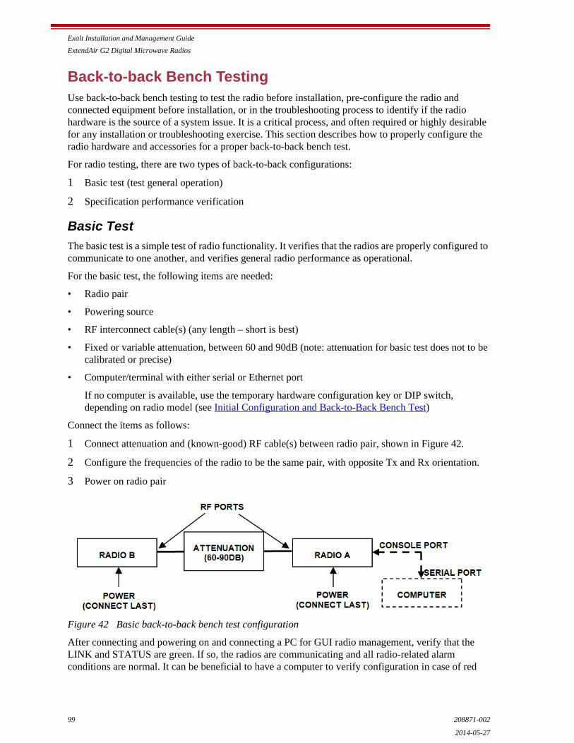
Exalt Installation and Management Guide
ExtendAir G2 Digital Microwave Radios
99 208871-002
2014-05-27
Back-to-back Bench TestingUse back-to-back bench testing to test the radio before installation, pre-configure the radio and connected equipment before installation, or in the troubleshooting process to identify if the radio hardware is the source of a system issue. It is a critical process, and often required or highly desirable for any installation or troubleshooting exercise. This section describes how to properly configure the radio hardware and accessories for a proper back-to-back bench test.
For radio testing, there are two types of back-to-back configurations:
1 Basic test (test general operation)
2 Specification performance verification
Basic Test
The basic test is a simple test of radio functionality. It verifies that the radios are properly configured to communicate to one another, and verifies general radio performance as operational.
For the basic test, the following items are needed:
• Radio pair
• Powering source
• RF interconnect cable(s) (any length – short is best)
• Fixed or variable attenuation, between 60 and 90dB (note: attenuation for basic test does not to be calibrated or precise)
• Computer/terminal with either serial or Ethernet port
If no computer is available, use the temporary hardware configuration key or DIP switch, depending on radio model (see Initial Configuration and Back-to-Back Bench Test)
Connect the items as follows:
1 Connect attenuation and (known-good) RF cable(s) between radio pair, shown in Figure 42.
2 Configure the frequencies of the radio to be the same pair, with opposite Tx and Rx orientation.
3 Power on radio pair
Figure 42 Basic back-to-back bench test configuration
After connecting and powering on and connecting a PC for GUI radio management, verify that the LINK and STATUS are green. If so, the radios are communicating and all radio-related alarm conditions are normal. It can be beneficial to have a computer to verify configuration in case of red

Exalt Installation and Management Guide
ExtendAir G2 Digital Microwave Radios
208871-002 1002014-05-27
LEDs or to pre-configure the radio as desired for operation. Follow the instructions in Configuration and Management.
Specification Performance Verification
The specification performance verification is a more detailed test that allows you to verify that the radio’s output power and threshold specifications are being met. This is typically a test that would only be performed in a troubleshooting scenario, but can be performed before installation to provide a detailed record or ensure radio performance before installation.
This test is identical to the basic test, but in place of the fixed attenuation, it requires the use of calibrated variable attenuation, or a set of calibrated fixed attenuators, or a combination of both, adding to a total attenuation value of 120dB, as measured at the operating frequency of the radio. In addition, a volt meter or computer is also required.
Connect the system as shown in Figure 42, using the combination of fixed and variable attenuation between the radio’s RF ports. Connect the volt meter to either radio’s RSL test point and associated reference ground connection.
In this test, it is desirable to use pre-tested RF cables, known to be good, and the insertion loss is known at the operating frequency. If the cables are short (6'/2m or less), you can estimate the loss, including connectors, to be less than 1dB each. The estimate of cable loss is critical to the overall confidence of the measurements made in this test.
There are two critical specifications that can be tested in this configuration:
• RF output power
• Radio receiver threshold
To measure transmitter output power, simply insert any value of attenuation between the radios between 60 and 90dB. Ensure that both RF output power settings are at maximum. Use the volt meter to measure RSL in both directions. The RSL measured value should match the appropriate value according to the inserted attenuation, such as:
RSL = RF Output Power – cabling losses – total attenuation
Verify output power by adjusting output power using the Exalt GUI (in administration mode) and evaluate the corresponding change to the RSL measurement.
For threshold testing, the key is to insert a measured amount of loss that is close to, but not exceeding the radio’s specified system gain. System gain is the difference between RF output power and receiver threshold. At your selected modulation and bandwidth settings, determine the specified threshold performance, and choose a value of attenuation (including cable losses) that adds to roughly 5 to 15dB less than the system gain.
For example, if the threshold for your measurement is –85dBm, the output power is +27dBm, so the system gain is 112dB. Choose a value of total attenuation in the range of roughly 100–105dB. Once this attenuation is inserted, verify RSL readings as in the first step, and then, using the GUI, reduce radio output power in 1dB steps until the receiving radio (the one whose output power not being adjusted) Link LED turns from green to yellow. This indicates that threshold has been reached. At this point, verify the equation for system gain using the new output power level setting and verify that the threshold performance is meeting or exceeding the published specification.
Note: Due to the variation of measurements and accuracies involved in this test, you may read a measurement that is 1dB to as much as 2dB off of the expected value. It should be of no concern unless the value is more than 3dB worse than expected.

Exalt Installation and Management Guide
ExtendAir G2 Digital Microwave Radios
101 208871-002
2014-05-27
Once threshold is verified in this direction, repeat the process in the opposite direction by adjusting RF output power of the radio at the opposite end. Return the first radio to its original power setting before adjusting the second radio.
Exalt Installation and Management Guide
ExtendAir G2 Digital Microwave Radios
208871-002 1022014-05-27
General Compliance and SafetyThe usage of radio transmission devices is subject to specific regulatory requirements governed by regional legislation. In most cases, the specific device must be authorized for use in a given country and must be installed and adjusted in accordance with specific radio-frequency settings and in a manner that has been authorized specific to the device itself in accordance with the specific location of the device. Some users may be completely or partially restricted from use of the device. Please consult local governmental agency/agencies for regulatory requirements before use, or contact Exalt or your Exalt authorized dealer for assistance.
Do not modify this device in any way without the express written consent of Exalt. Modification voids the manufacturer warranty, and may also be illegal in accordance to government regulations. In addition, there are no user-serviceable parts or assemblies inside the product housing. There may also be voltages, signals, and mechanisms within the device that could be harmful to human safety.
The mounting of this device and associated peripherals and connections (inclusive of antenna mast, antenna, cabling, egress, lightning protection devices, grounding, power, and so on) may be subject to regional requirements for health and human safety. A qualified professional installer and an electrician are highly recommended, and may be required by law.

Exalt Installation and Management Guide
ExtendAir G2 Digital Microwave Radios
103 208871-002
2014-05-27
Safety Notices1 Review this entire guide for important installation instructions BEFORE attempting to install this
product.
2 This product is intended to be installed, used, and maintained by experienced telecommunications personnel only.
3 Employ a properly licensed or authorized electrician to install or evaluate/certify the installation of all power and grounding related to the use of this equipment and all connected devices.
4 The device(s) shall only be connected to AC power sources provided by the supplier or to DC sources within the device specifications. Use a separate breaker circuit at the power source.
5 Lightning, surge protection devices, and earth grounding are required for most installations to ensure human safety. Consult a qualified electrician.
6 Servicing of this device should be performed by authorized personnel only. Do not disassemble this device. By opening or removing any covers you may expose yourself to hazardous energy parts. Incorrect reassembly of this product can cause a malfunction, and/or electrical shock, when the unit is subsequently used.
7 Do not connect or disconnect the power connection to the device when the power supply is plugged into an AC outlet. To connect, first connect the power connection to the device, and then apply power (or plug in) at the outlet. To disconnect, disengage power at the outlet or unplug, and then disconnect the direct connection to the device.
8 Do not insert any object of any shape or size inside this product at any time, whether powered or not. Objects may contact hazardous energy components that could result in a risk of fire or personal injury.
9 Liquids shall not come in contact with, or enter the inside of the device at any time.
10 Proper ventilation and/or airflow shall be provided surrounding the equipment. Items shall not come in contact with heat-sinking materials. Ensure that ambient operational and storage temperature specifications are maintained at all times.
11 Equipment is suitable for mounting on noncombustible surfaces only.
12 Do not move or alter the marking labels.
13 A CSU or similar isolating device is necessary between the equipment and the public telecommunications network. The equipment has not been evaluated for direct connection to the public telecommunications network.

Exalt Installation and Management Guide
ExtendAir G2 Digital Microwave Radios
208871-002 1042014-05-27
Regulatory NoticesThis section presents the Regulatory Compliance Regulations for your country.
United States Compliance
The ExtendAir G2 product family operates under FCC Rule Parts 101 as a licensed device. They may only be used as a point-to-point transmission device for fixed or temporary-fixed (non-mobile) installations. The devices are subject to the following restrictions:
• Do not use external amplifiers to boost the power or overcome transmission system losses, unless the specific amplifier/cable/antenna combination has expressly been authorized by the FCC. The output power must never exceed +30 dBm.
• Cross-border transmissions are expressly prohibited, except with written permission from both the FCC and the governing body of the neighboring country (Cofetel for Mexico; Industry Canada for Canada).
• Use only parabolic dish antennas. No other types of antennas (omni-directional, yagi, and so on) are authorized.
Federal Communications Commission (FCC), United States
The device is allowed to be used provided it does not cause interference to other devices. It is not guaranteed to provide protection against interference from other electronic and radio devices.
The system has been tested and found to comply with the limits of a Class B digital device, pursuant to Part 15 of the FCC Rules. These limits are designed to provide reasonable protection against harmful interference in a residential installation. This equipment generates uses and can radiate radio frequency energy and, if not installed and used in accordance with the instructions, may cause harmful interference to radio communications. However, there is no guarantee that interference will not occur in a particular installation. If this equipment does cause harmful interference to radio or television reception, which can be determined by turning the equipment off and on, the user is encouraged to try to correct the interference by one of more of the following measures:
• Reorient or relocate the receiving antenna.
• Increase the separation between the equipment and receiver.
• Connect the equipment into an outlet on a circuit different from that to which the receiver is connected.
• Consult the dealer or an experienced radio/TV technician for help.
Shielded cables and I/O cords must be used for this equipment to comply with the relevant FCC regulations.
Changes or modifications not expressly approved in writing by Exalt may void the user’s authority to operate this equipment.
This device must be professionally installed.
To comply with regulations, the output power of this device may need to be adjusted in accordance to the associated transmission system. See RF Output Power Setting for details.
The antenna associated with ExtendAir G2 radios shall be mounted in a location that is at least 10 feet away from humans that may be subject to long-term or continuous exposure.

Exalt Installation and Management Guide
ExtendAir G2 Digital Microwave Radios
105 208871-002
2014-05-27
Canada Compliance
The ExtendAir G2 radios operate under RSS-210 of Industry Canada regulations. Operation is subject to the following conditions, unless express permission is granted by Industry Canada to operate in a different manner:
• External amplifiers cannot be used to boost the power or to overcome transmission system losses, unless the specific amplifier/cable/antenna combination is expressly authorized by Industry Canada.
• Cross-border transmissions are expressly prohibited, except with written permission from both Industry Canada and the governing body of the neighboring country (FCC for USA)
• Only parabolic dish antennas may be used. No other types of antennas (omni-directional, yagi, and so on) are authorized
Industry Canada (IC), Canada
This device complies with RSS-210 of Industry Canada. Operation is subject to the following two conditions:
1 this device may not cause interference, and
2 this device must accept any interference, including interference that may cause undesired operation of the device.

Exalt Installation and Management Guide
ExtendAir G2 Digital Microwave Radios
208871-002 1062014-05-27
Regulatory Compliance As of this printing, Exalt Communications, Inc. has approvals for the products that are covered by this manual, as indicated in Table 8. If your application or country is not listed, check with your Sales Representative for the current status.
Table 8 Product Approvals
Country 6GHz 7GHz 8GHz 11GHz 13GHz 15GHz 18GHz 23GHz 38GHz
Canada
United States
Exalt Installation and Management Guide
ExtendAir G2 Digital Microwave Radios
107 208871-002
2014-05-27
LicensingFrequency coordination for ExtendAir G2 radios is normally required by local regulations. To obtain and maintain licensing, consult the licensing authorities.
United States
In the US frequency coordination is often conducted by a Certified Frequency Coordinator (CFC), who coordinates spectrum allocation for the Federal Communications Commission (FCC). CFCs assist applicants with licensing. Applicants can also apply using the FCC‘s Universal Licensing System (ULS) online at:
http://wireless.fcc.gov/uls/index.htm?job=home
You must first register with the FCC to use the on-line system, and obtain an FCC Registration Number (FRN). The FRN identifies you in all transactions to the FCC.
Exalt provides ExtendAir G2 radio information to the following CFCs:
• Comsearch (www.comsearch.com/)
• Micronet Communications, Inc. (www.micronetcom.com)
Upon request, ExtendAir G2 radio information can be provided to any CFC.
Canada
In Canada frequency coordination is often conducted by a National Frequency Coordinator (NFC), who coordinates spectrum allocation for Industry Canada (IC). NFCs assist applicants in licensing. Applicants can also apply using the IC’s online system at:
http://sd.ic.gc.ca/engdoc/main.jsp#LicenceApplications
You must first register with the IC to use the online system.
Note: The professional installer is responsible to ensure that RF output power, channel assignment, bandwidth, and modulation are properly adjusted in accordance with local regulatory requirements and licensing, if any. Antenna models and polarization are usually specified within the licensing requirements.
Exalt Installation and Management Guide
ExtendAir G2 Digital Microwave Radios
208871-002 1082014-05-27
Copyright NoticesThis section presents copyright notices for third-party software licensed to Exalt Communications, Inc.
Net-SNMP
The following copyright notice applies to the open-source licensing agreement for Net-SNMP.
Copyright 1989, 1991, 1992 by Carnegie Mellon University
Derivative Work - 1996, 1998-2000
Copyright 1996, 1998-2000 The Regents of the University of California
All Rights Reserved
Permission to use, copy, modify and distribute this software and its documentation for any purpose and without fee is hereby granted, provided that the above copyright notice appears in all copies and that both that copyright notice and this permission notice appear in supporting documentation, and that the name of CMU and The Regents of the University of California not be used in advertising or publicity pertaining to distribution of the software without specific written permission.
CMU AND THE REGENTS OF THE UNIVERSITY OF CALIFORNIA DISCLAIM ALL WARRANTIES WITH REGARD TO THIS SOFTWARE, INCLUDING ALL IMPLIED WARRANTIES OF MERCHANTABILITY AND FITNESS. IN NO EVENT SHALL CMU OR THE REGENTS OF THE UNIVERSITY OF CALIFORNIA BE LIABLE FOR ANY SPECIAL, INDIRECT OR CONSEQUENTIAL DAMAGES OR ANY DAMAGES WHATSOEVER RESULTING FROM THE LOSS OF USE, DATA OR PROFITS, WHETHER IN AN ACTION OF CONTRACT, NEGLIGENCE OR OTHER TORTIOUS ACTION, ARISING OUT OF OR IN CONNECTION WITH THE USE OR PERFORMANCE OF THIS SOFTWARE.
Network Associates Technology, Inc.
Copyright (c) 2001-2003, Networks Associates Technology, Inc
All rights reserved.
Redistribution and use in source and binary forms, with or without modification, are permitted provided that the following conditions are met:
* Redistributions of source code must retain the above copyright notice, this list of conditions and the following disclaimer.
* Redistributions in binary form must reproduce the above copyright notice, this list of conditions and the following disclaimer in the documentation and/or other materials provided with the distribution.
* Neither the name of the Networks Associates Technology, Inc nor the names of its contributors may be used to endorse or promote products derived from this software without specific prior written permission.
THIS SOFTWARE IS PROVIDED BY THE COPYRIGHT HOLDERS AND CONTRIBUTORS ''AS IS'' AND ANY EXPRESS OR IMPLIED WARRANTIES, INCLUDING, BUT NOT LIMITED TO, THE IMPLIED WARRANTIES OF MERCHANTABILITY AND FITNESS FOR A PARTICULAR PURPOSE ARE DISCLAIMED. IN NO EVENT SHALL THE COPYRIGHT HOLDERS OR CONTRIBUTORS BE LIABLE FOR ANY DIRECT, INDIRECT, INCIDENTAL, SPECIAL, EXEMPLARY, OR CONSEQUENTIAL DAMAGES (INCLUDING, BUT NOT LIMITED TO, PROCUREMENT OF SUBSTITUTE GOODS OR SERVICES; LOSS OF USE, DATA, OR PROFITS; OR BUSINESS INTERRUPTION) HOWEVER CAUSED AND ON ANY THEORY OF LIABILITY, WHETHER IN CONTRACT, STRICT LIABILITY, OR TORT (INCLUDING
Exalt Installation and Management Guide
ExtendAir G2 Digital Microwave Radios
109 208871-002
2014-05-27
NEGLIGENCE OR OTHERWISE) ARISING IN ANY WAY OUT OF THE USE OF THIS SOFTWARE, EVEN IF ADVISED OF THE POSSIBILITY OF SUCH DAMAGE.
Cambridge Broadband, Ltd.
Portions of this code are copyright (c) 2001-2003, Cambridge Broadband Ltd.
All rights reserved.
Redistribution and use in source and binary forms, with or without modification, are permitted provided that the following conditions are met:
* Redistributions of source code must retain the above copyright notice, this list of conditions and the following disclaimer.
* Redistributions in binary form must reproduce the above copyright notice, this list of conditions and the following disclaimer in the documentation and/or other materials provided with the distribution.
* The name of Cambridge Broadband Ltd. may not be used to endorse or promote products derived from this software without specific prior written permission.
THIS SOFTWARE IS PROVIDED BY THE COPYRIGHT HOLDER ``AS IS'' AND ANY EXPRESS OR IMPLIED WARRANTIES, INCLUDING, BUT NOT LIMITED TO, THE IMPLIED WARRANTIES OF MERCHANTABILITY AND FITNESS FOR A PARTICULAR PURPOSE ARE DISCLAIMED. IN NO EVENT SHALL THE COPYRIGHT HOLDER BE LIABLE FOR ANY DIRECT, INDIRECT, INCIDENTAL, SPECIAL, EXEMPLARY, OR CONSEQUENTIAL DAMAGES (INCLUDING, BUT NOT LIMITED TO, PROCUREMENT OF SUBSTITUTE GOODS OR SERVICES; LOSS OF USE, DATA, OR PROFITS; OR BUSINESS INTERRUPTION) HOWEVER CAUSED AND ON ANY THEORY OF LIABILITY, WHETHER IN CONTRACT, STRICT LIABILITY, OR TORT (INCLUDING NEGLIGENCE OR OTHERWISE) ARISING IN ANY WAY OUT OF THE USE OF THIS SOFTWARE, EVEN IF ADVISED OF THE POSSIBILITY OF SUCH DAMAGE.
Sun Microsystems, Inc.
Copyright © 2003 Sun Microsystems, Inc., 4150 Network Circle, Santa Clara,
California 95054, U.S.A. All rights reserved.
Use is subject to license terms below.
This distribution may include materials developed by third parties.
Sun, Sun Microsystems, the Sun logo and Solaris are trademarks or registered trademarks of Sun Microsystems, Inc. in the U.S. and other countries.
Redistribution and use in source and binary forms, with or without modification, are permitted provided that the following conditions are met:
* Redistributions of source code must retain the above copyright notice, this list of conditions and the following disclaimer.
* Redistributions in binary form must reproduce the above copyright notice, this list of conditions and the following disclaimer in the documentation and/or other materials provided with the distribution.
* Neither the name of the Sun Microsystems, Inc. nor the names of its contributors may be used to endorse or promote products derived from this software without specific prior written permission.
THIS SOFTWARE IS PROVIDED BY THE COPYRIGHT HOLDERS AND CONTRIBUTORS ''AS IS'' AND ANY EXPRESS OR IMPLIED WARRANTIES, INCLUDING, BUT NOT LIMITED TO, THE IMPLIED WARRANTIES OF MERCHANTABILITY AND FITNESS FOR A PARTICULAR
Exalt Installation and Management Guide
ExtendAir G2 Digital Microwave Radios
208871-002 1102014-05-27
PURPOSE ARE DISCLAIMED. IN NO EVENT SHALL THE COPYRIGHT HOLDERS OR CONTRIBUTORS BE LIABLE FOR ANY DIRECT, INDIRECT, INCIDENTAL, SPECIAL, EXEMPLARY, OR CONSEQUENTIAL DAMAGES (INCLUDING, BUT NOT LIMITED TO, PROCUREMENT OF SUBSTITUTE GOODS OR SERVICES; LOSS OF USE, DATA, OR PROFITS; OR BUSINESS INTERRUPTION) HOWEVER CAUSED AND ON ANY THEORY OF LIABILITY, WHETHER IN CONTRACT, STRICT LIABILITY, OR TORT (INCLUDING NEGLIGENCE OR OTHERWISE) ARISING IN ANY WAY OUT OF THE USE OF THIS SOFTWARE, EVEN IF ADVISED OF THE POSSIBILITY OF SUCH DAMAGE.
Sparta, Inc.
Copyright (c) 2003-2005, Sparta, Inc
All rights reserved.
Redistribution and use in source and binary forms, with or without modification, are permitted provided that the following conditions are met:
* Redistributions of source code must retain the above copyright notice, this list of conditions and the following disclaimer.
* Redistributions in binary form must reproduce the above copyright notice, this list of conditions and the following disclaimer in the documentation and/or other materials provided with the distribution.
* Neither the name of Sparta, Inc nor the names of its contributors may be used to endorse or promote products derived from this software without specific prior written permission.
THIS SOFTWARE IS PROVIDED BY THE COPYRIGHT HOLDERS AND CONTRIBUTORS ''AS IS'' AND ANY EXPRESS OR IMPLIED WARRANTIES, INCLUDING, BUT NOT LIMITED TO, THE IMPLIED WARRANTIES OF MERCHANTABILITY AND FITNESS FOR A PARTICULAR PURPOSE ARE DISCLAIMED. IN NO EVENT SHALL THE COPYRIGHT HOLDERS OR CONTRIBUTORS BE LIABLE FOR ANY DIRECT, INDIRECT, INCIDENTAL, SPECIAL, EXEMPLARY, OR CONSEQUENTIAL DAMAGES (INCLUDING, BUT NOT LIMITED TO, PROCUREMENT OF SUBSTITUTE GOODS OR SERVICES; LOSS OF USE, DATA, OR PROFITS; OR BUSINESS INTERRUPTION) HOWEVER CAUSED AND ON ANY THEORY OF LIABILITY, WHETHER IN CONTRACT, STRICT LIABILITY, OR TORT (INCLUDING NEGLIGENCE OR OTHERWISE) ARISING IN ANY WAY OUT OF THE USE OF THIS SOFTWARE, EVEN IF ADVISED OF THE POSSIBILITY OF SUCH DAMAGE.
Cisco, Inc.
Copyright (c) 2004, Cisco, Inc and Information Network
Center of Beijing University of Posts and Telecommunications.
All rights reserved.
Redistribution and use in source and binary forms, with or without modification, are permitted provided that the following conditions are met:
* Redistributions of source code must retain the above copyright notice, this list of conditions and the following disclaimer.
* Redistributions in binary form must reproduce the above copyright notice, this list of conditions and the following disclaimer in the documentation and/or other materials provided with the distribution.
* Neither the name of Cisco, Inc, Beijing University of Posts and Telecommunications, nor the names of their contributors may be used to endorse or promote products derived from this software without specific prior written permission.

Exalt Installation and Management Guide
ExtendAir G2 Digital Microwave Radios
111 208871-002
2014-05-27
THIS SOFTWARE IS PROVIDED BY THE COPYRIGHT HOLDERS AND CONTRIBUTORS ''AS IS'' AND ANY EXPRESS OR IMPLIED WARRANTIES, INCLUDING, BUT NOT LIMITED TO, THE IMPLIED WARRANTIES OF MERCHANTABILITY AND FITNESS FOR A PARTICULAR PURPOSE ARE DISCLAIMED. IN NO EVENT SHALL THE COPYRIGHT HOLDERS OR CONTRIBUTORS BE LIABLE FOR ANY DIRECT, INDIRECT, INCIDENTAL, SPECIAL, EXEMPLARY, OR CONSEQUENTIAL DAMAGES (INCLUDING, BUT NOT LIMITED TO, PROCUREMENT OF SUBSTITUTE GOODS OR SERVICES; LOSS OF USE, DATA, OR PROFITS; OR BUSINESS INTERRUPTION) HOWEVER CAUSED AND ON ANY THEORY OF LIABILITY, WHETHER IN CONTRACT, STRICT LIABILITY, OR TORT (INCLUDING NEGLIGENCE OR OTHERWISE) ARISING IN ANY WAY OUT OF THE USE OF THIS SOFTWARE, EVEN IF ADVISED OF THE POSSIBILITY OF SUCH DAMAGE.
Fabasoft R&D Software GmbH & Co.
Copyright (c) Fabasoft R&D Software GmbH & Co KG, 2003
Author: Bernhard Penz
Redistribution and use in source and binary forms, with or without modification, are permitted provided that the following conditions are met:
* Redistributions of source code must retain the above copyright notice, this list of conditions and the following disclaimer.
* Redistributions in binary form must reproduce the above copyright notice, this list of conditions and the following disclaimer in the documentation and/or other materials provided with the distribution.

Exalt Installation and Management Guide
ExtendAir G2 Digital Microwave Radios
208871-002 1122014-05-27
Exalt Installation and Management Guide
ExtendAir G2 Digital Microwave Radios
113 208871-002
2014-05-27
EXALT COMMUNICATIONS, INC. END USER AGREEMENT
(including Limited Hardware Warranty, Software License and RMA Procedure)
THIS IS AN AGREEMENT BETWEEN YOU (AS ORIGINAL END USER PURCHASER OF AN EXALT PRODUCT) AND EXALT COMMUNICATIONS, INC. ("EXALT"). THE END USER AGREEMENT APPLICABLE TO YOUR EXALT PRODUCT IS THE END USER AGREEMENT THAT IS PRE-LOADED ON THE EXALT PRODUCT, OF IF NONE IS PRE-LOADED, IT IS THE END USER AGREEMENT AVAILABLE ON THE EXALT WEBSITE @ WWW.EXALTCOM.COM/EULA ON THE DATE OF YOUR PURCHASE OF THE EXALT PRODUCT. BY ACCEPTING THIS AGREEMENT OR BY USING THE EXALT PRODUCT WITH OR FOR WHICH THIS AGREEMENT IS PROVIDED ("PRODUCT"), YOU ARE AGREEING TO ALL OF THE BELOW TERMS AND CONDITIONS. IF YOU DO NOT AGREE WITH THESE TERMS AND CONDITIONS, YOU SHOULD NOT USE THE PRODUCT AND PROMPTLY RETURN IT TO YOUR PLACE OF PURCHASE FOR A REFUND. "YOU" MEANS THE LEGAL END USER ENTITY THAT PURCHASED THE PRODUCT.
1 Exalt Limited Hardware Warranty
a. Exalt warrants solely to the original purchaser ("Purchaser") that the Exalt hardware product that this Agreement is provided with or for (the "Hardware Product") will substantially conform in all material respects to the relevant Exalt published specifications that apply at the time of manufacture of such Hardware Product for two (2) years from the date of purchase of Hardware Product by Purchaser (the "Warranty Period"). Proof-of-purchase in the form of an invoice, payment of invoice, or delivery waybill must be supplied, if requested by Exalt, in case of any dispute of warranty start date.
b. In the event Purchaser notifies Exalt during the Warranty Period of a defective Hardware Product (material nonconformance with the published specifications), Exalt shall within the Warranty Period, at its own option either: (A) use reasonable efforts to remedy any reproducible Hardware Product defect covered by this limited warranty within a reasonable period of time; (B) replace the defective Hardware Product with a functionally equivalent product (repair parts and products may be either reconditioned or new, but, if reconditioned, shall be of the same quality as new parts or products); or (C) if Exalt determines that it is unable to repair or replace such Hardware Product, Exalt (or its applicable reseller) will refund to Purchaser the amount actually paid by Purchaser for the applicable Hardware Product. All replaced parts and products become the property of Exalt.
c. The Exalt warranty does not cover any defective Hardware Product that (i) is subject to the exclusions set forth below in Section 3; (ii) cannot be demonstrated to have a defect of the types of defects covered by the Exalt warranty, or (iii) Purchaser is unable to provide adequate information describing how the Hardware Product failed that would allow Exalt to determine that the defect is covered by the Exalt warranty. Any Hardware Product that is returned by the Purchaser to Exalt and Exalt determines that such product is not covered by the Exalt warranty, will be, at Purchaser's option and expense (including any applicable shipping, handling, evaluation, repair, replacement and disposal fees), either be: (a) returned to Purchaser in the state received, (b) repaired or replaced, as applicable, and returned to Purchaser, or disposed of in accordance with Purchaser's instructions. Repaired or replaced Hardware Product will be warranted for the remainder of the original Warranty Period, but not less than ninety (90) days.
Exalt Installation and Management Guide
ExtendAir G2 Digital Microwave Radios
208871-002 1142014-05-27
2 Warranty Registration
In order to facilitate warranty service and communication with Exalt, Exalt recommends that the Purchaser registers the Hardware Product with Exalt promptly following the Hardware Product purchase by providing to Exalt the requested registration information. [Product registration may be performed by completing and submitting the product registration form on www.exaltcom.com/ProductRegistration ]
3 Limited Hardware Warranty Exclusions
This limited warranty will not apply to: (A) any Hardware Product that: (i) has been modified or altered by any party other than Exalt; (ii) has been subject to accident, misuse, neglect, or mistreatment; (iii) has been damaged during installation of the Hardware Product; (iv) has been damaged by failure of Purchaser or its agents to follow Exalt's instructions or specifications; (v) has been damaged by the equipment or system with which the Hardware Product is used; (vi) has sustained damage to the Hardware Products' interface or power connectors; (vii) is determined to be stolen; or (viii) has been damaged by water, fire, power changes, other hazards, or acts of God (including without limitation lightning); (B) any Software included in any such Hardware Product (see Software License below), or (C) any consumables. The warranty applies only to Hardware Products manufactured by or for Exalt and that can be identified by the Exalt trademark, trade name, serial number or logo affixed to them. Other products, including any third-party manufacturer products sold by Exalt on a resale basis, are subject to the applicable third-party manufacturer's warranty and end user agreement and are not warranted by Exalt. The Hardware Products covered by this warranty are not consumer products and are not intended for personal, family, or household purposes, nor are they intended for high-risk activities as described in Section 5 below.
4 Hardware Product RMA Procedure
A return material authorization (RMA) is required prior to returning Hardware Product to Exalt for in-warranty or out-of-warranty repair/evaluation. As such, Purchaser must use the then current Exalt RMA procedure. Such procedure is available on the Exalt website @ www.exaltcom.com/RMA.
PRODUCTS RETURNED WITHOUT A DULY ISSUED RMA NUMBER WILL BE RETURNED TO PURCHASER BY EXALT AT PURCHASER'S EXPENSE.
5 PRODUCT WARRANTY DISCLAIMER AND LIMITATION OF LIABILITY
a. THE ABOVE EXPRESS LIMITED WARRANTY FOR THE HARDWARE PRODUCT, THE CONDITIONS AND OTHER TERMS SET FORTH IN THIS AGREEMENT ARE IN LIEU OF ALL OTHER WARRANTIES, CONDITIONS AND OTHER TERMS WHETHER EXPRESS, IMPLIED OR STATUTORY, REGARDING THE PRODUCT (HARDWARE PRODUCT AND SOFTWARE) AND ANY SERVICES PROVIDED BY EXALT, AND EXALT, ITS SUPPLIERS AND LICENSORS HEREBY EXPRESSLY DISCLAIM, TO THE EXTENT ALLOWED BY APPLICABLE LAW, ANY AND ALL SUCH EXPRESS, IMPLIED AND STATUTORY WARRANTIES, CONDITIONS AND OTHER TERMS, INCLUDING WITHOUT LIMITATION ANY AND ALL IMPLIED WARRANTIES OF FITNESS FOR A PARTICULAR PURPOSE, TITLE, INTERFERENCE WITH QUIET ENJOYMENT, NON-INFRINGEMENT OF THIRD-PARTY RIGHTS AND MERCHANTABILITY. FURTHER, EXALT DOES NOT WARRANT RESULTS OF USE OR THAT YOUR USE OF THE PRODUCT WILL BE UNINTERRUPTED OR ERROR FREE. NO WARRANTIES ARE MADE BY EXALT'S SUPPLIERS OR LICENSORS. EXCEPT FOR THE ABOVE EXPRESS LIMITED WARRANTY FOR THE HARDWARE PRODUCT, THE CONDITIONS AND OTHER TERMS STATED HEREIN, THE
Exalt Installation and Management Guide
ExtendAir G2 Digital Microwave Radios
115 208871-002
2014-05-27
PRODUCT IS PROVIDED "AS IS" AND WITH ALL FAULTS. THE ENTIRE RISK AS TO SATISFACTORY QUALITY, ACCURACY, AND EFFORT IS WITH YOU.
b. THE PRODUCT IS NOT FAULT-TOLERANT AND IS NOT DESIGNED, MANUFACTURED OR INTENDED FOR USE OR RESALE AS ONLINE CONTROL EQUIPMENT IN HAZARDOUS ENVIRONMENTS REQUIRING FAIL-SAFE PERFORMANCE, SUCH AS IN THE OPERATION OF NUCLEAR FACILITIES, AIRCRAFT NAVIGATION OR COMMUNICATION SYSTEMS, AIR TRAFFIC CONTROL, DIRECT LIFE SUPPORT MACHINES OR WEAPONS SYSTEMS, IN WHICH THE FAILURE OF THE PRODUCT COULD LEAD DIRECTLY TO DEATH, PERSONAL INJURY, OR SEVERE PHYSICAL OR ENVIRONMENTAL DAMAGE. EXALT AND ITS SUPPLIERS AND LICENSORS SPECIFICALLY DISCLAIM ANY EXPRESS OR IMPLIED WARRANTY OF FITNESS FOR ANY HIGH-RISK USES LISTED ABOVE.
c. REGARDLESS OF WHETHER ANY REMEDY SET FORTH HEREIN FAILS OF ITS ESSENTIAL PURPOSE OR OTHERWISE, AND TO THE EXTENT ALLOWED BY APPLICABLE LAW, IN NO EVENT WILL EXALT, ITS SUPPLIERS OR LICENSORS BE LIABLE TO YOU OR TO ANY THIRD PARTY UNDER ANY TORT, CONTRACT, NEGLIGENCE, STRICT LIABILITY OR OTHER LEGAL OR EQUITABLE THEORY FOR ANY LOST PROFITS, LOST OR CORRUPTED DATA, COMPUTER FAILURE OR MALFUNCTION, INTERRUPTION OF BUSINESS, OR OTHER SPECIAL, INDIRECT, INCIDENTAL OR CONSEQUENTIAL DAMAGES OF ANY KIND ARISING OUT OF (1) THE USE OR INABILITY TO USE THE PRODUCT OR (2) PRODUCT RELATED SERVICE OR SUPPORT, EVEN IF EXALT HAS BEEN ADVISED OF THE POSSIBILITY OF SUCH LOSS OR DAMAGES AND WHETHER OR NOT SUCH LOSS OR DAMAGES ARE FORESEEABLE.
d. IN NO EVENT SHALL EXALT'S AND ITS SUPPLIERS'/LICENSORS' AGGREGATE LIABILITY EXCEED AN AMOUNT EQUAL TO THE PURCHASE PRICE PAID BY PURCHASER FOR THE PRODUCT OR SERVICE THAT IS THE SUBJECT OF A CLAIM. ANY CLAIM ARISING OUT OF OR RELATING TO THIS AGREEMENT MUST BE BROUGHT WITHIN ONE (1) YEAR AFTER THE OCCURRENCE OF THE EVENT GIVING RISE TO SUCH CLAIM. IN ADDITION, EXALT DISCLAIMS ALL LIABILITY OF ANY KIND OF EXALT'S SUPPLIERS/LICENSORS.
6 SOFTWARE LICENSE
a. Subject to the terms and conditions of this Agreement, Exalt hereby grants You a non-exclusive, non-transferable, non-sublicensable license to use the Software that comes with the Product, if any is provided as part of the Product, only as part of the normal operation, use and maintenance of the Hardware Product for which the Software was provided. You may make back-up copies of such Software. You shall not otherwise copy, distribute or alter the Software. Furthermore, except to the extent allowed by applicable law if located in the European Union, and then only with prior written notice to Exalt, You shall not disassemble or reverse engineer the Software in whole or in part or authorize others to do so. No rights to distribute or sublicense the Software are granted herein.
b. There may be certain third party owned software provided along with, or incorporated within the Product ("Third Party Software"), and which Third Party Software has a separate license agreement and which is governed exclusively by such separate license agreement ("Third Party License") and not this Agreement. Such Third Party Software and applicable Third Party Licenses are listed in the document "EXALT COMMUNICATIONS, INC. THIRD PARTY SOFTWARE AND THIRD PARTY LICENSES USED WITH CERTAIN EXALT
Exalt Installation and Management Guide
ExtendAir G2 Digital Microwave Radios
208871-002 1162014-05-27
PRODUCTS" available through the Web user interface application provided with this product. Except as Exalt may otherwise inform You in writing, the Third Party License gives You at least the license rights granted above in Section 6(a), and may provide additional license rights as to the Third Party Software, but only with respect to the particular Third Party Software to which the Third Party License applies. SUCH THIRD PARTY SOFTWARE IS PROVIDED WITHOUT ANY WARRANTY FROM EXALT AND ITS LICENSORS, INCLUDING BUT NOT LIMITED TO WARRANTIES OF MERCHANTABILITY, FITNESS FOR A PARTICULAR PURPOSE AND NON-INFRINGEMENT.
c. Exalt and its licensors are the sole and exclusive owners of the Software, and all underlying intellectual property rights in the Software and Hardware Product. All rights not expressly granted to You relating to the Software are reserved by Exalt and its licensors. You take unencumbered title to the Hardware Product, subject to Exalt's and its licensors' ownership in the underlying intellectual property, upon payment in full to Exalt or the Exalt reseller for the Product(s).
d. All licenses to the Software hereunder shall terminate if You fail to comply with any of the provisions of this Agreement and do not remedy such breach within thirty (30) days after receiving written notice from Exalt. You agree upon termination to immediately cease using the Software and to destroy all copies of the Software which may have been provided or created hereunder.
7 GOVERNMENT RESTRICTIONS
a. You agree that you will not export or re-export the Products without Exalt's prior written consent, and then only in compliance with all requirements of applicable law, including but not limited to U.S. export control regulations. You have the responsibility to obtain any required licenses to export, re-export or import the Products. You shall defend, indemnify and hold Exalt and its suppliers/licensors harmless from any claims arising out of Your violation of any export control laws relating to any exporting of the Products. By accepting this Agreement and receiving the Products, You confirm that You are not listed on any governmental export exclusion lists and will not export or re-export the Products to any country embargoed by the U.S. Applicable export restrictions and exclusions are available at the official web site of the U.S. Department of Commerce Bureau of Industry and Security (www.bis.doc.gov).
b. For purchase by or on behalf of governmental entities (including federal, state or provincial, and local), the governmental entity's rights in any technical data and software in the Products include only those rights customarily provided to the public as defined in Exalt's standard End User Agreement. In connection with any purchase by or on behalf of a U.S. governmental entity, Exalt's customary commercial license in technical data and software is provided in accordance with FAR 12.211 (Technical Data) and FAR 12.212 (Software) and, for Department of Defense transactions, DFAR 252.227-7015 (Technical Data - Commercial Items) and DFAR 227.7202-3 (Rights in Commercial Computer Software or Computer Software Documentation). If a governmental entity has a need for rights not conveyed under these terms, it must negotiate a mutually acceptable written agreement with Exalt specifying and specifically conveying such rights. Any use, modification, reproduction, release, performing, displaying or disclosing of the Exalt Software by a governmental entity shall be governed solely by the terms of this Agreement.
8 CONFIDENTIALITY
Purchaser acknowledges and agrees that information supplied by Exalt in connection with the Product or this Agreement and designated by Exalt as confidential is the confidential information
Exalt Installation and Management Guide
ExtendAir G2 Digital Microwave Radios
117 208871-002
2014-05-27
of Exalt, which confidential information includes the Software. Purchaser agrees: (i) to hold the confidential information in confidence using the same degree of care that it uses to protect its own confidential information of similar importance, but not less than a reasonable degree of care, (ii) not to make use of confidential information other than as contemplated by this Agreement, and (iii) not to reproduce confidential information except as expressly authorized by this Agreement. Purchaser's obligations with respect to confidentiality do not apply to information which: (i) becomes generally available to the public other than as a result of unauthorized disclosure by Purchaser, or (ii) was in Purchaser's possession prior to disclosure by Exalt.
9 MISCELLANEOUS
You shall not sell, transfer or assign this Agreement without the prior written consent of Exalt. Any act in derogation of the foregoing shall be null and void, and You will remain obligated under this Agreement. This Agreement shall benefit and be binding upon the parties to this Agreement and their respective permitted successors and assigns. The waiver or failure of either party to exercise in any respect any right provided for in this Agreement shall not be deemed a waiver of any further right under this Agreement. If any provision of this Agreement is held by a court of competent jurisdiction to be contrary to law, the remaining provisions of this Agreement will remain in full force and effect. This Agreement and any disputes arising out of, or related to, this Agreement, its termination or the relationship of the parties will be governed by and construed in accordance with the laws of the State of California, excluding its conflict of laws principles and excluding the United Nations Convention on Contracts for the International Sale of Goods. All disputes arising in connection with this Agreement, the Products or Services shall be administered by the American Arbitration Association under its commercial arbitration rules by a single arbitrator appointed in accordance with the rules. Both parties consent that the arbitration shall take place in Santa Clara County, California. The award rendered by the arbitrator shall be final and binding on the parties and judgment on the award may be entered in any court having jurisdiction thereof. Any litigation relating to this Agreement or the arbitration shall take place in the state courts of Santa Clara County or in the federal courts of the Northern District of California. The foregoing notwithstanding, Exalt may obtain preliminary and/or permanent injunctive relief in any court of competent jurisdiction worldwide to enforce the terms of Sections 6, 7 and 8. Purchaser hereby consents and submits to the jurisdiction and venue of these courts and agrees that process may be served in the manner provided or allowed by California or federal law. In any action or proceeding to enforce rights under this Agreement, the prevailing party shall be entitled to recover costs and attorneys' fees. This Agreement represents the complete agreement and understanding of the parties with respect to the subject matter herein. This Agreement may be modified only through a written instrument signed or otherwise agreed to by both parties.
-----------------------------------------
Part Number 203985
Revision 2.1, 5/1/2014
Exalt Confidential
Exalt Installation and Management Guide
ExtendAir G2 Digital Microwave Radios
208871-002 1182014-05-27
IndexAACM 43Adaptive Coded Modulation (ACM) 43Administration Settings page 32administrator privileges 26Advance Encryption Standard 33AES 33alarm conditions 29alarms 54, 62
clearing 62Ethernet 54Link 54
Alarms page 54antennas
alignment 23, 97mounting 21mounting height 5polarization orientation 5site preparation considerations 5system grounding 5troubleshooting 97
ATPC 52Bback-to-back bench test 6, 99back-to-back bench test configuration 99bandwidth 5Bandwidth parameter 40, 43BER 65browsers 25Ccables
troubleshootingimproper transmission system 96
waveguide 5carrier-to-interference tolerance 5CLI 24
menu options 25root menu 24
connectorsEthernet 92front panel 15
critical parameter reset 9Current BER field 56Current RSL field 57Ddate and time 32
DC power source 16Diagnostic Charts page 65dimensions-ExtendAir models 70Eeffective isotropic radiated power (EIRP) 7Endpoint Identifier 39Errored Seconds (ES) field 56Ethernet configuration parameters 40Ethernet connectors 92Ethernet interface 91Ethernet Interface Configuration page 45Event Log page 62Ffactory default settings 39fade margin 5, 97File Activation page 41files
activating stored 41default configuration file 39
Ggateway (default) 39grounding 97GUI
Administration Settings page 32Alarms page 54ATPC configuration page 52ATPC Statistics page 59browsers supported 25description 25Diagnostic Charts page 65Ethernet Interface Configuration page 45Ethernet Learning 50Ethernet Rate Limiting 49Event Log page 62File Activation page 41IP address (default) 25log in 26login privileges 26navigation panel 28, 30Radio Information page 31Radio Performance page 56Reboot page 68summary status information 29Syslog configuration 51VLAN page 47
Exalt Installation and Management Guide
ExtendAir G2 Digital Microwave Radios
119 208871-0022014-05-27
Iinterfaces
DC power 91Ethernet 91RF 91
interference 57interference profile 5internal diplexer 5IP address 39IP subnet mask 39LLicense Key 33lightning arrestor 5link 5link margin 97Link Name parameter 40link parameters 28Link Security Key 32Link Security Key parameter 40login names 27login privileges 26MMaximum RSL field 57Media Access Control (MAC) learning 50Minimum RSL field 57Minimum RSL Timestamp field 57Mode parameter 43modulation 5mounting the radio 13multipath 95multipath propagation 96muting 45Nnoise profile 5Pparameters
critical reset 9passwords 27, 40path obstruction 97performance degradation 95power
DC power 6power interface 91Rradio
grounding 5, 97initiation tasks 11
installation tasks 11maximum transmit power setting 43mounting 5rebooting 68transmitter output power 5
radio configuration 6Radio Information page 31Radio Name parameter 39Radio Performance page 56Reboot page 68received signal level (RSL) See RSLreceiver threshold 5record keeping 12RF connection termination 17RF Frequency parameter 40RF interface 91RF interference 96RF output power 7RSL 7
current RSL readings 57diagnostics 65Maximum RSL field 57Minimum RSL Timestamp field 57monitor for performance 95
RSL voltage 23Ssafety 102shipping box contents 6site preparation 5SNMP 10, 35SNMP Traps 36specifications
ExtendAir 70Swap button 41system performance 56system settings
Current BER field 56, 57Errored Seconds (ES) field 56grounding 97Maximum RSL 57Minimum RSL field 57Time Since Reset field 57Unavailable Seconds field 57
system specifications 70TTelnet session 24temperature 65, 70

Exalt Installation and Management Guide
ExtendAir G2 Digital Microwave Radios
208871-002 1202014-05-27
testing 99back-to-back bench 6threshold 100
threshold testing 100time division duplex (TDD) See TDD frameTime Since Reset 57transmitter output power 5Transmitter/Receiver (TR) frequency param-eter 44traps 36troubleshooting 65, 94TX Frequency parameter 44UUnavailable Seconds (UAS) 57Update button 32user privileges 27VVLAN 9
tagging 9VLAN page 47voltage test 23VSWR 96

Exalt Installation and Management Guide
ExtendAir G2 Digital Microwave Radios
121 208871-0022014-05-27

208871-0022014-05-27