Exposed linear encoders - HEIDENHAIN€¦ · Exposed linear encoders consist of a scale or scale...
71
05/2019 Exposed Linear Encoders
Transcript of Exposed linear encoders - HEIDENHAIN€¦ · Exposed linear encoders consist of a scale or scale...

05/2019
Exposed Linear Encoders

Exposed linear encoders
Linear encoders measure the position of linear axes without additional mechanical transfer elements. A number of potential error sources are thereby eliminated:• Positioning error due to heat generation
in the recirculating ball screw• Reversal error• Kinematic error through the ball-screw
pitch error
Linear encoders are therefore indispensable for machine tools on which high positioning accuracy and a high machining rate are essential.
Exposed linear encoders are used on machines and equipment that require high measuring accuracy. Typical applications include the following:• Measuring and production equipment in
the semiconductor industry• PCB assembly machines• Ultra-precision machines and devices
such as diamond lathes for optical components, facing lathes for magnetic storage disks, and grinding machines for ferrite components
• High-accuracy machine tools• Measuring machines and comparators,
measuring microscopes, and other precision measuring devices
• Direct drives
Mechanical designExposed linear encoders consist of a scale or scale tape and a scanning head that operate without mechanical contact.The scales of exposed linear encoders are fastened to a mounting surface. High flatness of the mounting surface is thus an important requirement for the high accuracy of linear encoders.
Information on the following topics is available upon request or on the Internet at www.heidenhain.de:• Angle encoders with integral bearing• Modular angle encoders with optical
scanning• Modular angle encoders with magnetic
scanning• Rotary encoders• Encoders for servo drives• Linear encoders for numerically
controlled machine tools• Interface electronics• HEIDENHAIN controls
This brochure supersedes all previous editions, which thereby become invalid.The basis for ordering from HEIDENHAIN is always the brochure edition valid when the order is made.
Standards (ISO, EN, etc.) apply only where explicitly stated in the brochure.
Further information:
For comprehensive descriptions of all available interfaces, as well as general electrical information, please refer to the Interfaces of HEIDENHAIN Encoders brochure.

Overview
Exposed linear encoders 2
Selection guide 4
Technical characteristics
Measuring principles 8
Reliability 12
Measuring accuracy 14
Mechanical design types and mounting 17
General mechanical information 21
Functional safety 22
Specifications
For absolute position measurement LIC 4113, LIC 4193 24
LIC 4115, LIC 4195 26
LIC 4117, LIC 4197 28
LIC 4119, LIC 4199 30
LIC 4119 FS 32
LIC 2117, LIC 2197 34
LIC 2119, LIC 2199 36
For high accuracy LIP 382 38
LIP 211, LIP 281, LIP 291 40
LIP 6071, LIP 6081 42
LIF 471, LIF 481 44
For high traversing speed LIDA 473, LIDA 483 46
LIDA 475, LIDA 485 48
LIDA 477, LIDA 487 50
LIDA 479, LIDA 489 52
LIDA 277, LIDA 287 54
LIDA 279, LIDA 289 56
For two-coordinate measurement PP 281 R 58
Electrical connection
Interfaces 60
Testing equipment and diagnostics 67
Interface electronics 69
Contents

4
Selection guideAbsolute encoders and encoders with position value output
Absolute position measurementThe LIC exposed linear encoders permit absolute position measurement over long traverse paths of up to 28 m at high traversing speed.
Encoders for use in a vacuum environmentHEIDENHAIN standard encoders are suitable for use in rough or fine vacuums. Encoders used in high and ultrahigh vacuums must meet special requirements. The design and materials used for such encoders must be specifically tailored to these conditions. For more information, please refer to the Linear Encoders for Vacuum Technology Technical Information document.
The LIC 4113 V and LIC 4193 V linear encoders are specifically designed for use in high vacuums. For more information, please refer to the appropriate Product Information documents.
Incremental encoders with position value outputThe LIP 211 and LIP 291 incremental linear encoders output the position information as a position value. For this to occur, the sinusoidal scanning signals are highly interpolated in the scanning head and converted into a position value by the integrated counter function. As with all incremental encoders, the absolute reference is established by means of reference marks.
Baseline error Substrate and mounting Interpolation error
Signal period
Measuring length
Interface Model Page
Accuracy grade
Interval
LIC 4100For high accuracy and high traversing speed
±1 µm1)
±3 µm±5 µm
±0.275 µm/10 mm
Glass or glass ceramic scale, adhesively bonded to the mounting surface or fastened with fixing clamps
±20 nm – 240 mm to 3040 mm
EnDat 2.2 LIC 4113 24
Fanuc Þi Mitsubishi Panasonic Yaskawa
LIC 4193
±5 µm ±0.750 µm/50 mm (typical)
Steel scale tape drawn into aluminum extrusions and tensioned
±20 nm – 140 mm to 28 440 mm
EnDat 2.2 LIC 4115 26
Fanuc Þi Mitsubishi Panasonic Yaskawa
LIC 4195
±3 µm2)
±5 µm3)
±15 µm4)
±0.750 µm/50 mm (typical)
Steel scale tape drawn into aluminum extrusions and secured
±20 nm – 240 mm to 6040 mm
EnDat 2.2 LIC 4117 28
Fanuc Þi Mitsubishi Panasonic Yaskawa
LIC 4197
±3 µm±15 µm4)
±0.750 µm/50 mm (typical)
Steel scale tape, adhesively bonded to mounting surface
±20 nm – 70 mm to 1020 mm
EnDat 2.2 LIC 4119 30
Fanuc Þi Mitsubishi Panasonic Yaskawa
LIC 4199
70 mm to 1820 mm
EnDat 2.2 LIC 4119 32
LIC 2100For high traversing speed
±15 µm – Steel scale tape drawn into aluminum extrusions and secured
±2 µm – 120 mm to 3020 mm
EnDat 2.2 LIC 2117 34
Fanuc Þi Mitsubishi Panasonic Yaskawa
LIC 2197
±15 µm – Steel scale tape, adhesively bonded to mounting surface
±2 µm – 120 mm to 3020 mm
EnDat 2.2 LIC 2119 36
Fanuc Þi Mitsubishi Panasonic Yaskawa
LIC 2199
LIP 200For very high accuracy
±1 µm2)
±3 µm ±0.125 µm/5 mm
Scale made of Zerodur glass ceramic, fastened with fixing clamps
±0.4 nm5) 0.512 µm 20 mm to 3040 mm
EnDat 2.2 LIP 211 40
Fanuc Þi Mitsubishi
LIP 291
1) Up to a measuring length (ML) of 1640 mm2) Up to a measuring length (ML) of 1020 mm or 1040 mm
3) For a measuring length (ML) of 1240 mm or greater4) ±5 µm after linear length-error compensation in the evaluation electronics5) With HEIDENHAIN interface electronics

LIC 41x3
LIC 41x5
LIC 41x7
LIC 21x7
LIC 21x9
LIP 211
5
Baseline error Substrate and mounting Interpolation error
Signal period
Measuring length
Interface Model Page
Accuracy grade
Interval
LIC 4100For high accuracy and high traversing speed
±1 µm1)
±3 µm±5 µm
±0.275 µm/10 mm
Glass or glass ceramic scale, adhesively bonded to the mounting surface or fastened with fixing clamps
±20 nm – 240 mm to 3040 mm
EnDat 2.2 LIC 4113 24
Fanuc Þi Mitsubishi Panasonic Yaskawa
LIC 4193
±5 µm ±0.750 µm/50 mm (typical)
Steel scale tape drawn into aluminum extrusions and tensioned
±20 nm – 140 mm to 28 440 mm
EnDat 2.2 LIC 4115 26
Fanuc Þi Mitsubishi Panasonic Yaskawa
LIC 4195
±3 µm2)
±5 µm3)
±15 µm4)
±0.750 µm/50 mm (typical)
Steel scale tape drawn into aluminum extrusions and secured
±20 nm – 240 mm to 6040 mm
EnDat 2.2 LIC 4117 28
Fanuc Þi Mitsubishi Panasonic Yaskawa
LIC 4197
±3 µm±15 µm4)
±0.750 µm/50 mm (typical)
Steel scale tape, adhesively bonded to mounting surface
±20 nm – 70 mm to 1020 mm
EnDat 2.2 LIC 4119 30
Fanuc Þi Mitsubishi Panasonic Yaskawa
LIC 4199
70 mm to 1820 mm
EnDat 2.2 LIC 4119 32
LIC 2100For high traversing speed
±15 µm – Steel scale tape drawn into aluminum extrusions and secured
±2 µm – 120 mm to 3020 mm
EnDat 2.2 LIC 2117 34
Fanuc Þi Mitsubishi Panasonic Yaskawa
LIC 2197
±15 µm – Steel scale tape, adhesively bonded to mounting surface
±2 µm – 120 mm to 3020 mm
EnDat 2.2 LIC 2119 36
Fanuc Þi Mitsubishi Panasonic Yaskawa
LIC 2199
LIP 200For very high accuracy
±1 µm2)
±3 µm ±0.125 µm/5 mm
Scale made of Zerodur glass ceramic, fastened with fixing clamps
±0.4 nm5) 0.512 µm 20 mm to 3040 mm
EnDat 2.2 LIP 211 40
Fanuc Þi Mitsubishi
LIP 291
1) Up to a measuring length (ML) of 1640 mm2) Up to a measuring length (ML) of 1020 mm or 1040 mm
3) For a measuring length (ML) of 1240 mm or greater4) ±5 µm after linear length-error compensation in the evaluation electronics5) With HEIDENHAIN interface electronics

6
Selection guideIncremental encoders
Baseline error Substrate and mounting Interpolation error
Signal period
Measuring length
Interface Model Page
Accuracy grade1)
Interval
LIPFor very high accuracy
±0.5 µm3) ±0.075 µm/5 mm
Zerodur glass ceramic embedded within a screw-on Invar carrier
±0.01 nm 0.128 µm 70 mm to 270 mm
» 1 VPP LIP 382 38
±1 µm2)
±3 µm ±0.125 µm/5 mm
Scale made of Zerodur glass ce-ramic, fastened with fixing clamps
±0.4 nm7) 0.512 µm 20 mm to 3040 mm
» 1 VPP LIP 281 40
±1 µm5)
±3 µm ±0.175 µm/5 mm
Scale made of Zerodur glass ceramic or glass, adhesively bonded or fastened with fixing clamps
– 4 µm 20 mm to 3040 mm
« TTL LIP 6071 42
±4 nm » 1 VPP LIP 6081
LIFFor high accuracy
±1 µm8)
±3 µm ±0.225 µm/5 mm
Scale made of Zerodur glass ceramic or glass, adhesively bonded or fastened with fixing clamps
– 4 µm 70 mm to 3040 mm4)
« TTL LIF 171 Product Information±12 nm » 1 VPP LIF 181
±1 µm5)
±3 µm ±0.225 µm/5 mm
Scale made of Zerodur glass ceramic or glass, adhesively bonded by means of PRECIMET adhesive mounting film
– 4 µm 70 mm to 1640 mm
« TTL LIF 471 44
±12 nm » 1 VPP LIF 481
LIDAFor high traversing speeds and large measuring lengths
±1 µm9)
±3 µm±5 µm
±0.275 µm/10 mm
Scale made of glass or glass ceramic, adhesively bonded to the mounting surface
– 20 µm 240 mm to 3040 mm
« TTL LIDA 473 46
±45 nm » 1 VPP LIDA 483
±5 µm ±0.750 µm/50 mm (typical)
Steel scale tape drawn into aluminum extrusions and tensioned
– 20 µm 140 mm to 30040 mm
« TTL LIDA 475 48
±45 nm » 1 VPP LIDA 485
±3 µm2)
±5 µm±15 µm6)
±0.750 µm/50 mm (typical)
Steel scale tape drawn into aluminum extrusions and secured
– 20 µm 240 mm to 6040 mm
« TTL LIDA 477 50
±45 nm » 1 VPP LIDA 487
±3 µm2)
±15 µm6) ±0.750 µm/50 mm (typical)
Steel scale tape, adhesively bonded to mounting surface
– 20 µm Up to 6000 mm4)
« TTL LIDA 479 52
±45 nm » 1 VPP LIDA 489
±15 µm – Steel scale tape drawn into aluminum extrusions and secured
– 200 µm Up to 10 000 mm4)
« TTL LIDA 277 54
±2 µm » 1 VPP LIDA 287
±15 µm – Steel scale tape, adhesively bonded to mounting surface
– 200 µm Up to 10 000 mm4)
« TTL LIDA 279 56
±2 µm » 1 VPP LIDA 289
PPFor two-coordinate measurement
±2 µm – Glass grid plate, secured with full-surface adhesive bond
±12 nm7) 4 µm Measuring area: 68 x 68 mm4)
» 1 VPP PP 281 58
LIP/LIFFor use in high and ultrahigh vacuums
±0.5 µm±1 µm
±0.175 µm/5 mm
Scale made of Zerodur glass ceramic or glass, fastened with fixing clamps
±7 nm 2 µm 70 mm to 420 mm
» 1 VPP LIP 481 V LIP 481 U
Product Information
±3 µm ±0.225 µm/5 mm
±12 nm7) 4 µm 70 mm to 1020 mm
LIF 481 V
1) At an interval of 1 m or a measuring length < 1 m (accuracy grade)2) Up to measuring lengths of 1020 mm or 1040 mm3) Higher accuracy grades upon request4) Other measuring lengths / measuring ranges upon request
5) Only for Zerodur glass ceramic up to a measuring length of 1020 mm6) ±5 µm after linear length-error compensation in the subsequent electronics7) With HEIDENHAIN interface electronics (e.g., EIB 741)8) Up to a measuring length of 1640 mm9) Only for Robax glass ceramic up to a measuring length of 1640 mm
Very high accuracyThe LIP exposed linear encoders are characterized by their very small measuring steps combined with extremely high accuracy and repeatability. They utilize the interferential scanning principle and feature an OPTODUR phase grating as their measuring standard.
High accuracyThe LIF exposed linear encoders utilize the interferential scanning principle and possess a measuring standard made with the SUPRADUR process. They feature high accuracy and repeatability, are particularly easy to mount, and are equipped with limit switches and homing tracks. The special version LIF 481 V can be used in high vacuums of up to 10–7 millibars (see separate Product Information document).
High traversing speedsThe LIDA exposed linear encoders are designed for high traversing speeds of up to 10 m/s. Their various mounting options allow for particularly flexible deployment. Depending on the version, steel scale tapes, glass, or glass ceramic are used as the carriers for METALLUR gratings. They also feature limit switches.
Twocoordinate measurementThe measuring standard of the PP two-coordinate encoder is an interferentially scanned planar phase grating manufactured with the DIADUR process. Position measurement is thereby possible within a plane.
Encoders for use in vacuum environmentsHEIDENHAIN standard encoders are suitable for use in rough or fine vacuums. Encoders used in high and ultrahigh vacuums must meet special requirements. The design and materials used for such encoders must be specifically tailored to these conditions. For more information, please refer to the Linear Encoders for Vacuum Technology Technical Information document.
The following exposed linear encoders are specifically designed for use in a high and ultrahigh vacuum:• High vacuum: LIP 481 V and LIF 481 V• Ultrahigh vacuum: LIP 481 UFor more information, please refer to the appropriate Product Information documents.

LIF 481
LIP 6081
PP 281
LIDA 489
LIDA 287
LIP 382
LIP 281
7
Baseline error Substrate and mounting Interpolation error
Signal period
Measuring length
Interface Model Page
Accuracy grade1)
Interval
LIPFor very high accuracy
±0.5 µm3) ±0.075 µm/5 mm
Zerodur glass ceramic embedded within a screw-on Invar carrier
±0.01 nm 0.128 µm 70 mm to 270 mm
» 1 VPP LIP 382 38
±1 µm2)
±3 µm ±0.125 µm/5 mm
Scale made of Zerodur glass ce-ramic, fastened with fixing clamps
±0.4 nm7) 0.512 µm 20 mm to 3040 mm
» 1 VPP LIP 281 40
±1 µm5)
±3 µm ±0.175 µm/5 mm
Scale made of Zerodur glass ceramic or glass, adhesively bonded or fastened with fixing clamps
– 4 µm 20 mm to 3040 mm
« TTL LIP 6071 42
±4 nm » 1 VPP LIP 6081
LIFFor high accuracy
±1 µm8)
±3 µm ±0.225 µm/5 mm
Scale made of Zerodur glass ceramic or glass, adhesively bonded or fastened with fixing clamps
– 4 µm 70 mm to 3040 mm4)
« TTL LIF 171 Product Information±12 nm » 1 VPP LIF 181
±1 µm5)
±3 µm ±0.225 µm/5 mm
Scale made of Zerodur glass ceramic or glass, adhesively bonded by means of PRECIMET adhesive mounting film
– 4 µm 70 mm to 1640 mm
« TTL LIF 471 44
±12 nm » 1 VPP LIF 481
LIDAFor high traversing speeds and large measuring lengths
±1 µm9)
±3 µm±5 µm
±0.275 µm/10 mm
Scale made of glass or glass ceramic, adhesively bonded to the mounting surface
– 20 µm 240 mm to 3040 mm
« TTL LIDA 473 46
±45 nm » 1 VPP LIDA 483
±5 µm ±0.750 µm/50 mm (typical)
Steel scale tape drawn into aluminum extrusions and tensioned
– 20 µm 140 mm to 30040 mm
« TTL LIDA 475 48
±45 nm » 1 VPP LIDA 485
±3 µm2)
±5 µm±15 µm6)
±0.750 µm/50 mm (typical)
Steel scale tape drawn into aluminum extrusions and secured
– 20 µm 240 mm to 6040 mm
« TTL LIDA 477 50
±45 nm » 1 VPP LIDA 487
±3 µm2)
±15 µm6) ±0.750 µm/50 mm (typical)
Steel scale tape, adhesively bonded to mounting surface
– 20 µm Up to 6000 mm4)
« TTL LIDA 479 52
±45 nm » 1 VPP LIDA 489
±15 µm – Steel scale tape drawn into aluminum extrusions and secured
– 200 µm Up to 10 000 mm4)
« TTL LIDA 277 54
±2 µm » 1 VPP LIDA 287
±15 µm – Steel scale tape, adhesively bonded to mounting surface
– 200 µm Up to 10 000 mm4)
« TTL LIDA 279 56
±2 µm » 1 VPP LIDA 289
PPFor two-coordinate measurement
±2 µm – Glass grid plate, secured with full-surface adhesive bond
±12 nm7) 4 µm Measuring area: 68 x 68 mm4)
» 1 VPP PP 281 58
LIP/LIFFor use in high and ultrahigh vacuums
±0.5 µm±1 µm
±0.175 µm/5 mm
Scale made of Zerodur glass ceramic or glass, fastened with fixing clamps
±7 nm 2 µm 70 mm to 420 mm
» 1 VPP LIP 481 V LIP 481 U
Product Information
±3 µm ±0.225 µm/5 mm
±12 nm7) 4 µm 70 mm to 1020 mm
LIF 481 V
1) At an interval of 1 m or a measuring length < 1 m (accuracy grade)2) Up to measuring lengths of 1020 mm or 1040 mm3) Higher accuracy grades upon request4) Other measuring lengths / measuring ranges upon request
5) Only for Zerodur glass ceramic up to a measuring length of 1020 mm6) ±5 µm after linear length-error compensation in the subsequent electronics7) With HEIDENHAIN interface electronics (e.g., EIB 741)8) Up to a measuring length of 1640 mm9) Only for Robax glass ceramic up to a measuring length of 1640 mm

8
Measuring principlesMeasuring standard
HEIDENHAIN encoders with optical scanning use measuring standards consisting of periodic structures known as graduations. These graduations are applied to a carrier substrate made of glass or steel. For encoders with large measuring lengths, steel tape is used as the scale substrate.
HEIDENHAIN manufactures the precision graduations in the following specially developed, photolithographic processes:• METALLUR: contamination-tolerant
graduation consisting of metal lines on gold; typical graduation period: 20 µm
• SUPRADUR phase grating: optically three-dimensional, planar structure; particularly tolerant to contamination; typical graduation period: 8 µm and finer
• OPTODUR phase grating: optically three-dimensional, planar structure with particularly high reflectance; typical graduation period: 2 µm and finer
• TITANID phase grating: exceptionally robust optically three-dimensional structure with a high degree of reflectance; typical grating period: 8 µm
Along with the very fine grating periods, these processes permit high edge definition and excellent homogeneity of the graduation. Together with the photoelectric scanning method, this high edge definition is critical for the high quality of the output signals.
The master graduations are manufactured by HEIDENHAIN on custom-built, high-precision dividing engines.
Absolute measuring method
With the absolute measuring method, the position value is available immediately upon switch-on of the encoder and can be requested at any time by the subsequent electronics. There is no need to move the axes to find the reference position. The absolute position information is read from the graduation on the measuring standard, which is designed as a serial absolute code structure. A separate incremental track is interpolated for the position value and, depending on the interface version, is also used to generate an optional incremental signal.
Schematic representation of a code structure with an additional incremental track (example from the LIC 411x)
Graduation of an absolute linear encoder

9
Incremental measuring method
With the incremental measuring method, the graduation consists of a periodic grating structure. The position information is obtained by counting the individual increments (measuring steps) from some point of origin. Since an absolute reference is required to ascertain positions, the measuring standard is provided with an additional track that bears a reference mark. The absolute position on the scale, which is established by the reference mark, is assigned to exactly one signal period. The reference mark must therefore be scanned to establish an absolute reference or to find the last selected datum.
In the most unfavorable case, machine movements over sizeable sections of the measuring range may be necessary. To speed up and simplify such “reference runs,” many HEIDENHAIN encoders feature distancecoded reference marks—multiple reference marks that are variously spaced in accordance with a mathematical algorithm. The subsequent electronics find the absolute reference after traversing two successive reference marks—thus after a traverse path of only a few millimeters (see table below). Encoders with distance-coded reference marks are identified with a “C” following the model designation (e.g., LIF 181 C).
With distance-coded reference marks, the absolute reference B is calculated by counting the increments between two reference marks and by applying the following formula:
and
P1 = (abs R–sgn R–1) x N + (sgn R–sgn D) x abs MRR2 2
R = 2 x MRR–N
Where:P1 = Position of the first traversed
reference mark in signal periods
abs = Absolute value
sgn = Algebraic sign function (“+1” or “–1”)
MRR = Number of signal periods between the traversed reference marks
N = Nominal increment between two fixed reference marks in signal periods (see table below)
D = Direction of traverse (+1 or –1). Traverse of scanning unit to the right (when properly installed) equals +1
Graduations of incremental linear encoders
Schematic representation of an incremental graduation with distance-coded reference marks (LIDA 4x3 C as example)
Signal period
Nominal increment N in signal periods
Maximum traverse
LIF 1x1 C 4 µm 5000 20 mm
LIDA 4x3 C 20 µm 1000 20 mm

10
Photoelectric scanning
Most HEIDENHAIN encoders utilize the photoelectric scanning principle. Photoelectric scanning is performed without contact and thus does not induce wear. This method detects even extremely fine graduation lines with a width of only a few micrometers and generates output signals with very small signal periods.
The finer the grating period of a measuring standard is, the greater the effect of diffraction on photoelectric scanning. HEIDENHAIN linear encoders employ two scanning principles:
• The imaging scanning principle for grating periods from 10 µm to 200 µm.
• The interferential scanning principle for very fine grating periods of 4 µm and smaller.
Imaging scanning principlePut simply, the imaging scanning principle uses projected-light signal generation: two gratings with, for example, equal or similar grating periods—the scale and the scanning reticle—are moved relative to each other. The carrier material of the scanning reticle is transparent, whereas the graduation of the measuring standard may likewise be applied to a transparent material or to a reflective material.
When parallel light passes through a grating, light and dark fields are projected at a particular distance. At this location there is an index grating with the same or similar grating period. When the two graduations move relative to each other, the incident light is modulated: If the gaps are aligned, light passes through. If the lines of one grating coincide with the gaps of the other, no light passes through. Photocells convert these light fluctuations into electrical signals. The specially structured grating of the scanning reticle filters the light to generate nearly sinusoidal output signals. The smaller the grating period of the grating structure is, the closer and more tightly toleranced the gap must be between the scanning reticle and the scale. Workable mounting tolerances of an encoder with the imaging scanning principle are achieved with grating periods of 10 µm and larger.
The LIC and LIDA linear encoders use the imaging scanning principle.
Signal period360° elec.
90° elec.
Phase shift
Scale WindowStructured detector
Scanning reticle
Index grating
Condenser lens
LED light source
Photoelectric scanning in accordance with the imaging principle with a steel scale and single-field scanning (LIDA 400)

11
The sensor generates four nearly sinusoidal current signals (I0°, I90°, I180°, and I270°), phase-shifted to each other by 90° elec. These scanning signals do not initially exhibit symmetry about the zero line. For this reason, the photocells are connected in anti-parallel, thereby producing two 90° elec. phase-shifted output signals, I1 and I2, which are symmetrical about the zero line.
In the X/Y representation on an oscilloscope, the signals form a Lissajous figure. Ideal output signals appear as a centered circle. Deviations in the circular form and position are caused by position errors and therefore go directly into the result of measure-ment. The size of the circle, which corresponds to the amplitude of the output signal, can vary within certain limits without influencing the measuring accuracy.
Photoelectric scanning in accordance with the interferential measuring principle and single-field scanning
Scale
Orders of diffraction–1 0 +1
Scale graduation with DIADUR phase grating
Grating period
Scanning reticle: transparent phase grating Photocells
LED light source
Condenser lens
Interferential scanning principleThe interferential scanning principle exploits the diffraction and interference of light on finely divided gratings in order to produce the signals used to measure displacement.
A step grating is used as the measuring standard: reflective lines with a height of 0.2 µm are applied to a flat, reflective surface. In front of this is the scanning reticle—a transparent phase grating with the same grating period as the scale.
When a light wave passes through the scanning reticle, it is diffracted into three partial waves of the orders +1, 0, and –1, with nearly equal luminous intensity. The waves are diffracted by the scale such that most of the luminous intensity is found in the reflected diffraction orders +1 and –1. These partial waves meet again at the phase grating of the scanning reticle, where they are diffracted again and interfere. This produces essentially three waves that leave the scanning reticle at different angles. Photocells convert these alternating light intensities into electrical signals.
When there is relative motion between the scale and the scanning reticle, the diffracted wavefronts undergo a phase shift: move-ment by the amount of one grating period shifts the positive first-order diffraction wavefront by one wavelength in the positive direction, while the negative first-order diffraction wavefront is displaced by one wavelength in the negative direction. Since the two waves interfere with each other upon exiting the phase grating, these waves are shifted relative to each other by two wavelengths. This results in two signal periods when there is relative motion of just one grating period.
Interferential encoders use grating periods of, for example, 8 µm, 4 µm, or finer. Their scanning signals are largely free of harmonics and can be highly interpolated. These encoders are therefore especially well-suited for small measuring steps and high accuracy. They nevertheless feature workable mounting tolerances.
The LIP, LIF, and PP linear encoders use the interferential scanning principle.
X/Y representation of the output signals

0 40 60 80 100 120
1.2
1.0
0.8
0.6
0.4
0.2
0
1
0
–1
100 nm
50 nm
0
–50 nm
–100 nm
12
Reliability
Exposed linear encoders from HEIDENHAIN are optimized for use on fast, precise machines. Despite their exposed mechanical design, these encoders are highly insensitive to contamination, ensure high long-term stability, and are quickly and easily mounted.
Lower sensitivity to contaminationBoth the high quality of the grating and the scanning method are responsible for the accuracy and reliability of linear encoders. Exposed linear encoders from HEIDENHAIN employ singlefield scanning, in which a single large scanning field is used to generate the scanning signals. Local contamination on the measuring standard (e.g., fingerprints from the mounting process or oil residues from guideways) has only a slight influence on the light intensity of the signal components and thus on the scanning signals. Although this contamination does cause a change in the amplitude of the output signals, their offset and phase position remain unaffected. The signals remain highly interpolable, and the position error within one signal period remains small.
The large scanning field further reduces the sensitivity to contamination. Depending on the nature of the contamination, this feature can even prevent encoder failure. This is particularly true of the LIDA 400 and LIF 400, which feature a very large scanning surface area (14.5 mm2) relative to their grating period. The same goes for the LIC 4100, which has a scanning surface area of 15.5 mm2. Even in the case of contamination from printer’s ink, PCB dust, or drops of water or oil up to 3 mm in diameter, these encoders continue to provide high-quality signals. The position error remains far below the values specified for the accuracy grade of the scale.
The LIDA, LIC, LIF, and LIP 6000 encoders are equipped with the HSP 1.0 signal processor ASIC from HEIDENHAIN. This ASIC continuously monitors the scanning signal and compensates nearly completely for fluctuations in signal amplitude. If the signal amplitude decreases as the result of contamination on the scanning reticle or measuring standard, the ASIC reacts by increasing the LED current. The ensuing increase in LED light intensity barely raises the noise level, even in the case of strong signal stabilization. As a result, contamination has only a very slight influence on interpolation errors and the position noise.
Measuring standard with contamination and the associated signal amplitudes with conventional scanning and scanning with the HSP 1.0 signal processing ASIC
Fingerprint Oil2)Oil1)Wire
Position in mm
Inte
rpo
lati
on
err
or
and
no
ise
in µ
m
Sig
nal
in V
PP
With HSP 1.0 signal processing ASICWithout HSP 1.0 signal processing ASIC
1), 2) = Oil drops ¬ 2 mm half1) or fully2) convering the incremental track

13
(e.g., LIDA 403/409)
LIF 400
Durable measuring standardsBy nature of their design, the measuring standards of exposed linear encoders are less protected from their environment. For this reason, HEIDENHAIN always uses tough gratings manufactured in special processes.
In the OPTODUR and SUPRADUR processes, a transparent layer is first applied onto the reflective primary layer. For creating an optically three-dimensional phase grating, an extremely thin, hard chrome layer is applied to a thickness of only a few nanometers. The graduations for the imaging scanning principle exhibit a similar design and are manufactured in the METALLUR process. A reflective gold layer is covered with a thin layer of glass. On it are chromium lines acting as absorbers. Since they are only several nanometers thick, these lines are semitransparent. Measuring standards with OPTODUR, SUPRADUR, or METALLUR graduations have proven to be particularly robust and insensitive to contamination because the low height of their structure leaves practically no surface for dust, dirt, or water particles to accumulate.
Workable mounting tolerancesVery small signal periods usually come with very narrow mounting tolerances for the gap between the scanning head and scale tape. This is the result of diffraction caused by the grating structures. Such diffraction can lead to a signal attenuation of 50 % upon a gap change of only ±0.1 mm. The interferential scanning principle and innovative index gratings on encoders that use the imaging principle allow for workable mounting tolerances despite tiny signal periods.
The mounting tolerances of exposed linear encoders from HEIDENHAIN have only a slight influence on the output signals. In particular, the specified distance tolerance between the scale and scanning head (scanning gap) causes only a negligible change in the signal amplitude. During operation, the reliability and stability of the signals are additionally improved by the HSP 1.0. The two diagrams illustrate the correlation between the scanning gap and signal amplitude for the encoders of the LIDA 400 and LIF 400 series.
Reflective layer
Transparent layer
Reflective primary layer
Substrate
OPTODURSUPRADUR
Sig
nal
am
plit
ud
e in
%
Sig
nal
am
plit
ud
e in
%
Scanning gap in mm
Scanning gap in mm
Mounting tolerance
Mounting tolerance
METALLUR
Transparent layer
Reflective primary layer
Semitransparent layer
= During mounting (without HSP 1.0)= During operation (with HSP 1.0)
= During mounting (without HSP 1.0)= During operation (with HSP 1.0)

14
Measuring accuracy
The accuracy of the linear measurement is mainly determined by• the quality of the graduation,• the quality of the graduation carrier,• the quality of the scanning process,• the quality of the signal processing
electronics, and by• how the encoder is installed within the
machine.
These factors can be subdivided into encoder-specific position errors and application-dependent factors. For assessment of the attainable system accuracy, all of the individual factors must be taken into account.
Encoderspecific position errorEncoder-specific position error includes• the accuracy of the measuring standard,• the accuracy of the interpolation, and• the position noise. Accuracy of the measuring standard The accuracy of the measuring standard is mainly determined by • the homogeneity and period definition
of the graduation,• the alignment of the graduation on its
carrier, and• the stability of the graduation carrier.
The accuracy of the measuring standard is indicated by the uncompensated maximum value of the baseline error. This accuracy is ascertained under ideal conditions via measurement of the position errors with a serially produced scanning head. The distance between the measuring points is equivalent to the integer multiple of the signal period. As a result, interpolation errors have no effect.
The accuracy grade a defines the upper limit of the baseline error within any section up to one meter in length. For special encoders, an additional baseline error is stated for defined intervals of the measuring standard.
Accuracy of the interpolationThe accuracy of the interpolation is mainly influenced by• the size of the signal period,• the homogeneity and period definition
of the graduation,• the quality of scanning filter structures,• the characteristics of the sensors, and• the quality of the signal processing.
The accuracy of the interpolation is ascertained with a serially produced measuring standard and is indicated by a typical maximum value u of the interpolation error. Encoders with an analog interface are tested with a HEIDENHAIN electronic device (e.g., EIB 741). The maximum values do not include position noise and are indicated in the specifications.
The interpolation error already has an effect at very low traversing speeds and during repeated measurements. This error leads to fluctuations in the traversing speed, particularly within the speed control loop.
Accuracy of the measuring standard
Posi
tio
n e
rro
r
Posi
tio
n e
rro
r
Sig
nal
leve
l PositionSignal period 360°
elec.
Accuracy of the interpolation
Baseline error
Position
Interpolation error

15
Position noisePosition noise is a random process leading to unpredictable position errors. The position values are grouped around an expected value in the form of a frequency distribution.
The amount of position noise depends on the signal processing bandwidths necessary for forming the position values. It is ascertained within a defined time interval and is stated as a product-specific RMS value.
In the velocity control loop, position noise influences the speed stability at low traversing speeds.
Applicationdependent position errorIn the case of encoders without integral bearing, installing the encoder in the machine has a significant influence on the attainable overall accuracy beyond the specified encoder-specific position error. For assessment of the overall accuracy, the individual application-dependent errors must be measured and taken into account.
Deformation of the graduationErrors due to a deformation of the graduation are not to be neglected. Such deformation occurs when the measuring standard is mounted on an uneven surface (e.g., a convex surface).
Mounting locationPoor mounting of linear encoders can aggravate the effect of guideway error on measuring accuracy. To keep the resulting Abbé error as small as possible, the scale should ideally be mounted to the machine slide and at the height of the table. It is important to ensure that the mounting surface is parallel to the machine guideway.
VibrationTo function properly, linear encoders must not be continuously subjected to strong vibration. The best mounting surfaces are therefore solid and stable machine elements. Encoders should not be mounted on hollow parts or with adapter blocks, etc.
Influence of temperatureIn order to avoid temperature effects, the linear encoders should not be mounted in close proximity to heat sources.
Time Frequency density
Position noise
Posi
tio
n e
rro
r
RM
S

LIP 201 R ID 631000-13 SN 44408260
Die Messkurve zeigt die Mittelwerte der Positionsabweichungen aus Vorwärts- und Rückwärtsmessung.
Positionsabweichung F des Maßstab: F = PosM – PosEPosM = Messposition der Messmaschine PosE = Messposition des Maßstab
The error curve shows the mean values of the position errors from measurements in forward and backward direction.
Position error F of the scale: F = PosM – PosEPosM = position measured by the measuring machinePosE = position measured by the scale
Quality Inspection CertificateDIN 55 350-18-4.2.2
Dieser Maßstab wurde unter den strengen HEIDENHAIN-Qualitätsnormen hergestellt und geprüft. Die Positionsabweichung liegt bei einer Bezugstemperatur von 20 °C innerhalb der Genauigkeitsklasse ± 1,0 µm.
Kalibriernormale Kalibrierzeichen
Jod-stabilisierter He-Ne LaserWasser-TripelpunktzelleGallium-SchmelzpunktzelleBarometerLuftfeuchtemessgerät
40151 PTB 1161 PTB 1062 PTB 10A6590 D-K-15092-01-00 2012-120230 DKD-K-30601 2012-11
This scale has been manufactured and inspected in accordance with the stringent quality standards of HEIDENHAIN. The position error at a reference temperature of 20 °C lies within the accuracy grade ± 1.0 µm.
Positionsabweichung F [µm]Position error F [µm]
Messparameter
Messschritt 1000 µm
Erster Referenzimpuls bei Messposition 335,0 mm
Relative Luftfeuchtigkeit max. 50 %
Unsicherheit der Messmaschine
U95% = 0,040 µm + 0,400 ·10–6 · L (L = Länge des Messintervalls)
Maximale Positionsabweichung der Messkurve
innerhalb 670 mm ± 0,30 µm
Measurement parameters
Measurement step 1000 µm
First reference pulse at measured position 335.0 mm
Relative humidity max. 50 %
Uncertainty of measuring machine
U95% = 0.040 µm + 0.400 ·10–6 · L (L = measurement interval length)
Calibration standards Calibration references
Iodine-stabilized He-Ne LaserWater triple point cellGallium melting point cellPressure gaugeHygrometer
40151 PTB 1161 PTB 1062 PTB 10A6590 D-K-15092-01-00 2012-120230 DKD-K-30601 2012-11
Maximum position error of the error curve
within 670 mm ± 0.30 µm
Messposition PosE [mm] / Measured position PosE [mm]
Qualitätsprüf-ZertifikatDIN 55 350-18-4.2.2
K. SommerauerPrüfer/Inspected by
28.01.2014
DR. JOHANNES HEIDENHAIN GmbH · 83301 Traunreut, Germany · www.heidenhain.de · Telefon: +49 8669 31-0 · Fax: +49 8669 5061
16
All HEIDENHAIN linear encoders are inspected for accuracy and proper functioning prior to shipping.
The accuracy of the linear encoders is ascertained during traversing movements in both directions. The number of measuring positions is selected such that not only the long-range errors but also the position errors within a single signal period are very accurately determined.
The Quality Inspection Certificate confirms the specified accuracy grades of each encoder. The calibration standards ensure traceability to recognized national or international standards, such as required by EN ISO 9001.
For the LIP and PP encoder series, an additional calibration chart documents the ascertained position error over the measuring range. It also specifies the measuring parameters and the measure-ment uncertainty.
Temperature rangeThe linear encoders are calibrated at a reference temperature of 20 °C. The position error documented in the calibration chart is valid at this temperature.
Calibration chart

17
Mechanical design types and mountingLinear scales
Exposed linear encoders are made up of two separate components: the scanning head and linear scale or scale tape, which are brought together solely over the machine guideway. For this reason, the machine must be designed from the very beginning to meet the following requirements:• The machine guideway must be designed
such that the scanning gap tolerances are complied with at the location where the encoder is installed (see Specifications)
• The mounting surface of the scale must meet the flatness requirements
• To facilitate adjustment of the scanning head to the scale, the scanning head should be fastened with a mounting bracket
Scale versionsHEIDENHAIN provides the appropriate scale version for the given application and accuracy requirements.
LIP 201LIP 6001LIC 4003The graduation carriers are fastened directly to the mounting surface with clamps. A holder is used to define the thermal fixed point.
Accessories for the LIC 41x3 and LIP 60x1:Fixing clamps ID 1176458-01Holder for thermal fixed point ID 1176475-01Spacer shims ID 1176441-01Adhesive* ID 1180444-01Double-cartridge gun ID 1180450-01Dispensing nozzles and mixing tubes ID 1176444-01
LIP 6001LIF 401LIDA 403LIC 4003The graduation carriers are adhesively bonded directly to the mounting surface with PRECIMET adhesive mounting film, with even pressure applied by means of a roller. A thermal fixed point can be established at a location with epoxy adhesive.
AccessoryRoller ID 276885-01
* Caution: no transport by air (dangerous goods) Trade name: 3M Scotch-Weld Epoxy Adhesive DP-460 EG
Scale LIP 6001LIC 4003
Scale LIF 101 C
ScaleLIP 6001LIF 401LIDA 403LIC 4003
Scale LIP 201

18
LIC 41x5LIDA 4x5Linear encoders of the LIC 41x5 and LIDA 4x5 series are specially designed for large measuring lengths. They are mounted with scale carrier sections screwed onto the mounting surface or adhesively bonded with PRECIMET adhesive mounting film. The single-piece steel scale tape is then pulled through the carrier, tensioned as specified, and secured at its ends to the machine base. The LIC 41x5 and LIDA 4x5 encoders thereby exhibit the same thermal behavior as that of the mounting surface.
LIC 21x7LIC 41x7LIDA 2x7LIDA 4x7Encoders of the LIC 41x7, LIC 21x7, LIDA 2x7, and LIDA 4x7 series are also designed for large measuring lengths. The scale carrier sections are adhesively bonded to the mount-ing surface with PRECIMET adhesive mount-ing film; the single-piece scale tape is pulled through, and the midpoint is secured to the machine bed. This mounting method allows the scale to expand freely at both ends and ensures a defined thermal behavior.
Accessory for LIC 41x7, LIDA 4x7Mounting aid ID 373990-01
Scale for LIC 4009, LIC 2109, LIDA 209/409
Scale for LIC 4005, LIDA 405
Scale for LIC 4007, LIC 2107, LIDA 207/407
Mounting aid (for LIC 41x7, LIDA 4x7)
LIC 21x9 LIC 41x9LIDA 2x9LIDA 4x9The steel scale tape of the graduation is adhesively bonded directly to the mounting surface with PRECIMET adhesive mounting film, with pressured applied evenly with a roller. A ridge or aligning rail with a height of 0.3 mm must be provided for the horizontal alignment of the scale tape.
Accessories for versions with PRECIMETRoller ID 276885-01Mounting aid, LIDA 2x9 ID 1070307-01Mounting aid, LIC 21x9 ID 1070853-01

LIP 200
LIC/LIDA
LIF 400
LIP 6000
19
Mechanical design types and mountingScanning heads
Because exposed linear encoders are assembled on the machine, they must be precisely adjusted after mounting. This adjustment determines the final accuracy of the encoder. It is therefore advisable to design the machine such that this adjustment is as easy and practical as possible, while also ensuring the greatest possible degree of mounting stability.
Mounting the LIP 2x1The LIP 2x can be fastened from the side as well as from above. The housing cover has a raised contact surface for the thermal con-nection to ensure optimal heat dissipation. The contact surface is compressed against the mounting element during mounting.
Mounting the LIP 60x1The LIP 60x can be fastened from the side as well as from above. When mounted from above, it is additionally possible to define a fixed center of rotation by inserting an alignment pin with ¬ 2 mm or ¬ 3 mm. This facilitates the alignment of the scanning head parallel to the scale. The alignment pin can be removed when mounting is completed.
Mounting the LIFThis scanning head features a centering collar with which the scanning head can be rotated in the location hole of the angle bracket and thereby aligned parallel to the scale.
Mounting the LIC/LIDAThere are three options for mounting the scanning head (see Dimensions). A spacer shim makes it quite easy to set the gap between the scanning head and the scale or scale tape. It is helpful to fasten the scanning head from behind with a mounting bracket. The scanning head can be very precisely adjusted through a hole in the mounting bracket with the aid of a tool.
AdjustmentThe gap between the scale and scanning head is easily adjusted with the aid of a spacer shim.
The signals from the LIC, LIP 6000, and LIP 200 can be quickly and easily adjusted with the aid of the PWM 20/21 adjustment and testing package. For all other exposed linear encoders, the incremental and reference mark signals are adjusted through a slight rotation of the scanning head (for the LIDA 400, it is possible with the aid of a tool).
HEIDENHAIN offers the appropriate measuring and testing devices as adjustment aids (see Testing equipment and diagnostics).
Spacer shim
Spacer shim
Spacer shim
3) Only with the LIDA 400
Spacer shim
Option 1
Option 2

20
Function indicator
The LIDA, LIF, and LIP 6071 linear encoders feature an integrated function indicator with a multicolor LED. This makes it possible to quickly and easily check the signal quality during normal operation.
The function indicator offers a number of benefits:• Indication of the scanning signal quality
via a multicolor LED• Continuous monitoring of incremental
signals over the entire measuring length• Function indicator of the reference-mark
signal• Quick check of correct operation in the
field without technical aids
The integrated function indicator permits both a reliable assessment of the incremental signals as well as a check of the reference mark signal. The quality of the incremental signals is indicated by color gradations that provide a detailed indication of the signal quality. Whether or not the reference mark signal complies with tolerances is shown by a pass/fail indicator.
LED indicator for incremental signals
LED color Quality of the scanning signals
Optimal
Good
Acceptable
Unsatisfactory
LED indicator for referencemarksignal (functional check)When the reference mark is traversed, the LED lights up briefly in blue or red: Out of tolerance Within tolerance
LIDA: function indicator in the scanning head
LIF, LIP 6071: function indicator in the interface electronics

21
AssemblyThe applicable steps and dimensions that must be complied with during mounting are specified solely in the mounting instructions supplied with the device. All mounting-related information in this brochure is therefore provisional and non-binding, and will not become the subject matter of a contract.
General mechanical information
Temperature rangeThe operating temperature range states the limits of ambient temperature within which the specifications of the linear encoder are complied with. The storage temperature range of –20 °C to +70 °C applies when the unit remains in its packaging.
Thermal characteristicsThe thermal behavior of the linear encoder is an essential criterion for the working accuracy of the machine. As a general rule, the thermal behavior of the linear encoder should match that of the workpiece or measured object. During temperature changes, the linear encoder should expand or contract in a defined, reproducible manner.
The graduation carriers of HEIDENHAIN linear encoders (see Specifications) have differing coefficients of thermal expansion. This makes it possible to select the linear encoder with the thermal behavior best suited to the application.
Parts subject to wearEncoders from HEIDENHAIN are designed for a long service life. Preventive mainte-nance is not required. However, they do contain components that are subject to wear, depending on the application and how they are deployed. This especially applies to cables subjected to frequent flexing. Other parts subject to wear are the bearings in encoders with integral bearing, the radial shaft seal rings in rotary encoders and angle encoders, and the sealing lips on linear encoders.
Protection (EN 60529)The scanning heads of exposed linear encoders feature the following degrees of protection:
Scanning head Protection
LIC IP67
LIDA IP40
LIF IP50
LIP 200 IP40
LIP 300LIP 6000
IP50
PP IP50
The scales have no special protection. If the scales are exposed to contamination, protective measures must be taken.
AccelerationLinear encoders are subjected to various types of acceleration during operation and mounting.• The indicated maximum values for
vibration apply to frequencies of 55 Hz to 2000 Hz (EN 6006826). If, depending on the application and the mounting scenario, the permissible acceleration values are exceeded (e.g., in the case of resonances), then the encoder can become damaged. Comprehensive testing of the entire system is therefore required
• The maximum permissible acceleration values (semi-sinusoidal shock) for shock and impact loads are valid for 11 ms or 6 ms (EN 60068227). Under no circumstances should a hammer or similar implement be used to adjust or position the encoder
System testsEncoders from HEIDENHAIN are usually integrated as components into complete systems. Such applications require comprehensive testing of the complete system, irrespective of the encoder’s specifications.
The specifications provided in this brochure apply to the specific encoder, not to the complete system. Any operation of the encoder outside of the specified range or outside of its proper and intended use is at the user’s own risk.
In safety-related systems, the encoder’s position value must be tested by the higher-level system after switch-on.
SUPRADUR, METALLUR, and OPTODUR are registered trademarks of DR. JOHANNES HEIDENHAIN GmbH, Traunreut, Germany.Zerodur is a registered trademark of Schott-Glaswerke, Mainz, Germany.

22
Functional safety
With the absolute linear encoders of the LIC 4100 series, HEIDENHAIN offers an ideal solution for position acquisition on linear axes in safety-related applications. In conjunction with a safe control, the encoders can be used as single-encoder systems in applications with control category SIL 2 (as per EN 61508) or performance level "d" (as per EN ISO 13849).
The reliable transmission of the position is based on two independently generated absolute position values and on error bits provided to the safe control. The functions of the encoder can be used for numerous safety functions of the complete system as per EN 61800-5-2.
The LIC 4100 linear encoder can provide a safe, absolute position value at any time—including immediately after switch-on. Purely serial data transfer takes place via the bidirectional EnDat 2.2 interface.
Fault exclusion for the loosening of the mechanical connectionThe machine manufacturer is responsible for the dimensioning of mechanical connections in a drive system. When planning the mechanical design, the OEM should ideally consider the conditions within the application. However, establishing proof of a safe connection is cost- and effort-intensive.For this reason, HEIDENHAIN has developed a mechanical fault exclusion for the LIC 4100 series and has confirmed it through a type examination.
Mechanical connection
Fastening Safe position for the mechanical coupling
Confined parameters3)
Scale Screw connection1) 2) ±0.0 mm See Specifications:• Vibration• Shock
See Mounting:• Usable materials• Mounting conditions
Scanning head Mounting configurations I and II:Screw connection:2)
M2x25 ISO 4762 8.8 screws
Mounting configuration III:Screw connection:2)
M2x16 ISO 4762 8.8 screws
1) A materially bonding anti-rotation lock is to be used for the screw connections of the scale (mounting/servicing)2) Friction class B as per VDI 22303) When compared with an LIC 4100 without functional safety
Mounting and operating conditionsThe qualification of the mechanical fault exclusion was performed for a broad range of encoder applications. As a result, fault exclusion is ensured for the following operating conditions.
In addition to the data interface, the me-chanical connection of the encoder to the drive is also safety-relevant. In table D8 of the standard for electrical drive systems, EN 61800-5-2, the loosening of the me-chanical connection between the encoder and the motor is listed as a fault that re-quires consideration. Since it cannot be guaranteed that the control will detect such errors, fault exclusion for the loosening of the mechanical connection is required in many cases.
Unless otherwise specified, HEIDENHAIN encoders are designed for a service life of 20 years (in accordance with ISO 13849).

23
MaterialThe material used for the mounting surfaces of the scanning head and measuring standard must comply with the specifications provided in the table.
Mounting temperatureAll of the information provided on screw connections assumes a mounting temperature of 15 °C to 35 °C.
Mounting the scanning headM2 screws as per ISO 4762 8.8 are to be used for the mechanical fault exclusion (included in delivery). A PWM20/21 and the mounting wizard of the ATS software are then used to check and optimize the mounting.
Mounting the scale tapeThe steel scale tape of the graduation is adhesively bonded directly to the mounting surface with PRECIMET adhesive mounting film, and pressure is applied evenly with a roller. The scale tape is additionally secured by a screw (punched hole in scale tape). The mounting aid (included in delivery) facilitates the symmetrical alignment of the screw to the punched hole.
Note:The scanning head may be operated only within the permissible mounting tolerances and measuring length of the measuring standard.
Included in delivery:Scanning head• Fastener kit ID 1233536-01
(2 x M2x16 screws)• Fastener kit ID 1233536-02
(2 x M2x25 screws)• Spacer shim ID 578983-06
Scale• One screw ID 1233558-01• Mounting aid ID 1244387-02
Accessories:• Mounting wizard in ATS software• Roller ID 276885-01
Angle bracket for scanning head Mounting surface for measuring standard
Material Steel Aluminum Steel, aluminum
Tensile strength Rm
600 N/mm2 220 N/mm2 Not applicable
Shear strength τB 390 N/mm2 130 N/mm2 Not applicable
Elastic modulus E 200 000 N/mm2 to 215 000 N/mm2
70 000 N/mm2 to 75 000 N/mm2
Not applicable
Coefficient of thermal expansion Þtherm
10 · 10–6 K–1 to17 · 10–6 K–1
25 · 10–6 K–1 10 · 10–6 K–1 to25 · 10–6 K–1

7.15±0.1
0.75 +0.25−0.20
0.75 +0.25−0.20 0.75 +0.25
−0.20
0.75 ±0.25
0.75 ±0.25 0.75 ±0.25
7.28±0.1
7.15±0.1 15.65 15.78 7.28±0.1
33.2
0.05
24
LIC 4113, LIC 4193Absolute linear encoders for measuring lengths of up to 3 m• Measuring steps of down to 1 nm• Glass or glass ceramic measuring standard• Measuring standard is secured with adhesive film or with fixing clamps• Consists of a linear scale and scanning head• Version available for use in a high vacuum (see separate Product Information document)
F = Machine guideway* = Mounting error plus dynamic guideway errorⓈ = Beginning of measuring length (ML)Ⓒ = Code start value: 100 ±1 mmⓁ = Scale lengthⒼ = Fixed-point element for defining the thermal fixed point1 = Gap is adjusted with a spacer shim during mounting2 = Depending on the measuring length (ML), use an additional pair of fixing clamps
Scale, clamped
Scale, adhesively bonded
Mounting possibilities for scanning head(shown without fixing clamps)
Clamped
Bonded
ClampedBonded
Clamped
Bonded
ClampedBonded
Clamped
Bonded
Clamped
Bonded

25
Linear scale LIC 4003
Measuring standardCoefficient of linear expansion*
METALLUR grating on glass ceramic or glassÞtherm � 8 · 10–6 K–1 (glass)Þtherm = (0 ±0.5) · 10–6 K–1 (Robax glass ceramic)
Accuracy grade* ±1 µm (only for Robax glass ceramic), ±3 µm, ±5 µm
Baseline error ±0.275 µm/10 mm
Measuring length (ML)* in mm
240 340 440 640 840 1040 1240 1440 1640 1840 2040 2240 24402640 2840 3040 (Robax glass ceramic only up to ML of 1640)
Mass 3 g + 0.11 g/mm of measuring length
Scanning head LIC 411 LIC 419 F LIC 419 M LIC 419 P LIC 419 Y
Interface EnDat 2.2 Fanuc Serial interface Þi
Mitsubishi high speed interface
Panasonic Serial Interface
Yaskawa Serial Interface
Ordering designation* EnDat22 Fanuc05 Mit03-4 Mit02-2 Pana01 YEC07
Measuring step* 0.01 µm (10 nm)0.005 µm (5 nm)0.001 µm (1 nm)1)
Calculation time tcalClock frequency
5 µs 16 MHz
–
Traversing speed2) 600 m/min
Interpolation error ±20 nm
Electrical connection* Cable, 1 m or 3 m, with 8-pin M12 coupling (male) or 15-pin D-sub connector (male)
Cable length (with HEIDENHAIN cable)
100 m 50 m 30 m 50 m
Supply voltage DC 3.6 V to 14 V
Power consumption2) (max.) At 3.6 V: 700 mWAt 14 V: 800 mW
At 3.6 V: 850 mWAt 14 V: 950 mW
Current consumption (typical) At 5 V: 75 mA (without load)
At 5 V: 95 mA (without load)
Vibration 55 Hz to 2000 HzShock 6 ms
500 m/s2 (EN 60068-2-6) 1000 m/s2 (EN 60068-2-27)
Operating temperature –10 °C to 70 °C
Mass Scanning head Connecting cable Connecting element
18 g (without cable)20 g/mM12 coupling: 15 g; Dsub connector: 32 g
* Please select when ordering1) Mitsubishi: measuring length 2040 mm Yaskawa: measuring length 1840 mm2) See General electrical information in the Interfaces of HEIDENHAIN Encoders brochure
Robax is a registered trademark of Schott-Glaswerke, Mainz, Germany

②②
②
6.23±0.1
6.1±0.1
12
3
8 >830±0.1
M3x7
16.53.5
1
3
R>8
2.5
0.55/50 *
7.3
3.
7
ML > 2040 (z.B. 5040)
9.6±0.1
9.6±0.1
18.1±0.1
18.23±0.1
26
LIC 4115, LIC 4195Absolute linear encoders for measuring lengths of up to 28 m• For measuring steps of down to 1 nm• Steel scale tape is drawn into the aluminum extrusions and tensioned• Consists of a linear scale and scanning head
Ô = Scale carrier sections secured with screwsÕ = Scale carrier sections secured with
PRECIMETF = Machine guidewayP = Measuring points for alignment* = Mounting error plus dynamic guideway errorⒸ = Code start value: 100 mmⓈ = Beginning of measuring length (ML)
Mounting possibilities for scanning head
ML > 2040 (e.g., 5040)
Ⓩ = Spacer for measuring lengths of 3040 mm or greater
Ⓣ = Carrier lengthⓂ = Mounting surface for scanning head1 = Optical centerline2 = Mounting clearance between scanning
head and extrusion3 = Direction of motion of the scanning unit for
ascending position values

27
Scale LIC 4005
Measuring standardCoefficient of linear expansion
Steel scale tape with absolute and incremental METALLUR trackDepends on the mounting surface
Accuracy grade ±5 µm
Baseline error ±0.750 µm/50 mm (typical)
Measuring length (ML)* in mm
140 240 340 440 540 640 740 840 940 1040 1140 1240 1340 14401540 1640 1740 1840 1940 2040
Greater measuring lengths of up to 28 440 mm with a single-section scale tape and individual scale carrier sections
Mass Scale tape Parts kit Scale tape carrier
31 g/m80 g + n1) · 27 g187 g/m
Scanning head LIC 411 LIC 419 F LIC 419 M LIC 419 P LIC 419 Y
Interface EnDat 2.2 Fanuc Serial Interface Þi
Mitsubishi high speed interface
Panasonic Serial Interface
Yaskawa Serial Interface
Ordering designation* EnDat22 Fanuc05 Mit03-4 Mit02-2 Pana01 YEC07
Measuring step* (note measuring length limitation2))
0.01 µm (10 nm)0.005 µm (5 nm)0.001 µm (1 nm)
Calculation time tcalClock frequency
5 µs 16 MHz
–
Traversing speed3) 600 m/min
Interpolation error ±20 nm
Electrical connection* Cable, 1 m or 3 m, with 8-pin M12 coupling (male) or 15-pin D-sub connector (male)
Cable length (with HEIDENHAIN cable)
100 m 50 m 30 m 50 m
Supply voltage DC 3.6 V to 14 V
Power consumption3) (max.) At 3.6 V: 700 mWAt 14 V: 800 mW
At 3.6 V: 850 mWAt 14 V: 950 mW
Current consumption (typical) At 5 V: 75 mA (without load)
At 5 V: 95 mA (without load)
Vibration 55 Hz to 2000 HzShock 6 ms
500 m/s2 (EN 60068-2-6) 1000 m/s2 (EN 60068-2-27)
Operating temperature –10 °C to 70 °C
Mass Scanning head Connecting cable Connecting element
18 g (without cable)20 g/mM12 coupling: 15 g; Dsub connector: 32 g
* Please select when ordering1) n = 1 for ML 3140 mm to 5040 mm; n = 2 for ML 5140 mm to 7040 mm; etc.*2) Mitsubishi: 1 nm: measuring length 2040 mm; 5 nm: measuring length 10 040 mm; 10 nm: measuring length 20 040 mm Yaskawa: 1 nm: measuring length 1840 mm; 5 nm: measuring length 9040 mm; 10 nm: measuring length 18 040 mm3) See General electrical information in the Interfaces of HEIDENHAIN Encoders brochure

0.55/50 *
②
② ②
③
①
②
28
LIC 4117, LIC 4197Absolute linear encoders for measuring lengths of up to 6 m• For measuring steps of down to 1 nm• Steel scale tape is drawn into the aluminum extrusions and fastened at center• Consists of a linear scale and scanning head
F = Machine guidewayP = Measuring points for alignment* = Mounting error plus dynamic guideway errorⒸ = Code start value: 100 mmⓈ = Beginning of measuring length (ML)Ⓣ = Carrier length1 = Optical centerline2 = Mounting clearance between scanning head and extrusion3 = Direction of motion of the scanning unit for ascending position values
Mounting possibilities for scanning head

29
Scale LIC 4007
Measuring standardCoefficient of linear expansion
Steel scale tape with absolute and incremental METALLUR trackÞtherm � 10 · 10–6 K–1
Accuracy grade* ±3 µm (up to ML 1040), ±5 µm (at ML 1240 or greater), ±15 µm1)
Baseline error ±0.750 µm/50 mm (typical)
Measuring length (ML)* in mm
240 440 640 840 1040 1240 1440 1640 1840 2040 2240 2440 2640 28403040 3240 3440 3640 3840 4040 4240 4440 4640 4840 5040 5240 5440 56405840 6040
Mass Scale tape Parts kit Scale tape carrier
31 g/m20 g68 g/m
Scanning head LIC 411 LIC 419 F LIC 419 M LIC 419 P LIC 419 Y
Interface EnDat 2.2 Fanuc Serial Interface Þi
Mitsubishi high speed interface
Panasonic Serial Interface
Yaskawa Serial Interface
Ordering designation* EnDat22 Fanuc05 Mit03-4 Mit02-2 Pana01 YEC07
Measuring step* 0.01 µm (10 nm)0.005 µm (5 nm)0.001 µm (1 nm)2)
Calculation time tcalClock frequency
5 µs 16 MHz
–
Traversing speed3) 600 m/min
Interpolation error ±20 nm
Electrical connection* Cable, 1 m or 3 m, with 8-pin M12 coupling (male) or 15-pin D-sub connector (male)
Cable length (with HEIDENHAIN cable)
100 m 50 m 30 m 50 m
Supply voltage DC 3.6 V to 14 V
Power consumption3) (max.) At 3.6 V: 700 mWAt 14 V: 800 mW
At 3.6 V: 850 mWAt 14 V: 950 mW
Current consumption (typical) At 5 V: 75 mA (without load)
At 5 V: 95 mA (without load)
Vibration 55 Hz to 2000 HzShock 6 ms
500 m/s2 (EN 60068-2-6) 1000 m/s2 (EN 60068-2-27)
Operating temperature –10 °C to 70 °C
Mass Scanning head Connecting cable Connecting element
18 g (without cable)20 g/mM12 coupling: 15 g; Dsub connector: 32 g
* Please select when ordering1) ±5 µm after linear length-error compensation in the evaluation electronics2) Mitsubishi: measuring length 2040 mm Yaskawa: measuring length 1840 mm3) See General electrical information in the Interfaces of HEIDENHAIN Encoders brochure

30
F = Machine guideway* = Mounting error plus dynamic guideway errorⒸ = Code start value: 100 mmⓈ = Beginning of measuring length (ML)Ⓛ = Scale tape length1 = Optical centerline2 = Mounting clearance between scanning head and linear scale3 = Direction of motion of the scanning unit for ascending position values
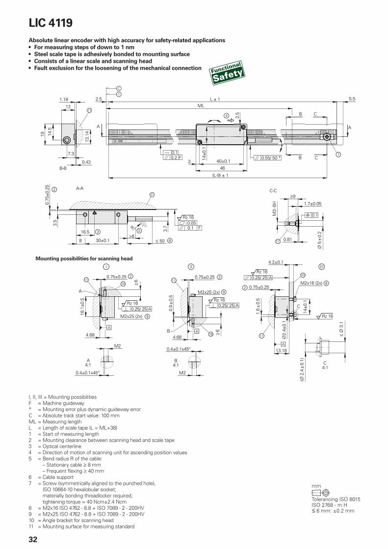
LIC 4119, LIC 4199Absolute linear encoders for measuring lengths of up to 1 m• For measuring steps of down to 1 nm• Steel scale tape is adhesively bonded to mounting surface• Consists of a linear scale and scanning head
Mounting possibilities for scanning head

31
Scale LIC 4009
Measuring standardCoefficient of linear expansion
Steel scale tape with absolute and incremental METALLUR trackÞtherm � 10 · 10–6 K–1
Accuracy grade* ±3 µm, ±15 µm1)
Baseline error ±0.750 µm/50 mm (typical)
Measuring length (ML)* in mm
70 120 170 220 270 320 370 420 520 620 720 820 920 1020
Mass 31 g/m
Scanning head LIC 411 LIC 419 F LIC 419 M LIC 419 P LIC 419 Y
Interface EnDat 2.2 Fanuc Serial Interface Þi
Mitsubishi high speed interface
Panasonic Serial Interface
Yaskawa Serial Interface
Ordering designation* EnDat22 Fanuc05 Mit03-4 Mit02-2 Pana01 YEC07
Measuring step* 0.01 µm (10 nm)0.005 µm (5 nm)0.001 µm (1 nm)2)
Calculation time tcalClock frequency
5 µs 16 MHz
–
Traversing speed3) 600 m/min
Interpolation error ±20 nm
Electrical connection* Cable, 1 m or 3 m, with 8-pin M12 coupling (male) or 15-pin D-sub connector (male)
Cable length (with HEIDENHAIN cable)
100 m4) 50 m 30 m 50 m
Supply voltage DC 3.6 V to 14 V
Power consumption3) (max.) At 3.6 V: 700 mWAt 14 V: 800 mW
At 3.6 V: 850 mWAt 14 V: 950 mW
Current consumption (typical) At 5 V: 75 mA (without load)
At 5 V: 95 mA (without load)
Vibration 55 Hz to 2000 HzShock 6 ms
500 m/s2 (EN 60068-2-6) 1000 m/s2 (EN 60068-2-27)
Operating temperature –10 °C to 70 °C
Mass Scanning head Connecting cable Connecting element
18 g (without cable)20 g/mM12 coupling: 15 g; Dsub connector: 32 g
* Please select when ordering1) ±5 µm after linear length-error compensation in the evaluation electronics2) Mitsubishi: measuring length 2040 mm Yaskawa: measuring length 1840 mm3) See General electrical information in the Interfaces of HEIDENHAIN Encoders brochure4) With LIC 411 FS scanning head: clock frequency: 8 MHz
A
B
B
C
C
ML2.5 L 5.5
463
(L-9)
12
0.43
1.18
13.1
4
7.3
M3
- 6H
0.1 F 0.55/ 50 *
B-B
2.5
14
9
5
3.1
2
.4
1.70.05
0.81
0.1
A
C-C
19 14.5
8 30
0.75
3.5
16.5
A-A
3.7
50>8
R 0.050.1 F
Rz 16
0.9
1.6
4.68
18.1
0.75 0.75
6
6
M2
M2x25 (2x)
0.25/ 25
A
M2x25 (2x)
Rz 16Rz 16
4.68
M20.4
0.4
A
B
4:1 4:1
A C4:1B
14
13.18
0.75
2.4
0.25/ 25
0.25/ 25M2x16 (2x)
Rz 16
Rz 16
A
A
4.2
AA
A
C
32
Mounting possibilities for scanning head
LIC 4119Absolute linear encoder with high accuracy for safetyrelated applications• For measuring steps of down to 1 nm• Steel scale tape is adhesively bonded to mounting surface• Consists of a linear scale and scanning head• Fault exclusion for the loosening of the mechanical connection
I, II, III = Mounting possibilitiesF = Machine guideway* = Mounting error plus dynamic guideway errorC = Absolute track start value: 100 mmML = Measuring lengthL = Length of scale tape (L = ML+38)1 = Start of measuring length2 = Mounting clearance between scanning head and scale tape3 = Optical centerline4 = Direction of motion of scanning unit for ascending position values5 = Bend radius R of the cable:
– Stationary cable 8 mm – Frequent flexing 40 mm
6 = Cable support7 = Screw (symmetrically aligned to the punched hole),
ISO 10664-10 hexalobular socket; materially bonding threadlocker required; tightening torque = 40 Ncm±2.4 Ncm
8 = M2x16 ISO 4762 - 8.8 + ISO 7089 - 2 - 200HV9 = M2x25 ISO 4762 - 8.8 + ISO 7089 - 2 - 200HV10 = Angle bracket for scanning head11 = Mounting surface for measuring standard

33
Scanning head5) LIC 411
Interface EnDat 2.2
Ordering designation EnDat22
Measuring step* 0.01 µm (10 nm)0.005 µm (5 nm)0.001 µm (1 nm)
Calculation time tcalClock frequency
5 µs 16 MHz
Functional safetyfor applications with up to
• SIL 2 as per EN 61508 (further basis for testing: EN 61800-5-2)• Category 3, PL "d "as per EN ISO 13849-1:2015
PFH 20 · 10–9 (up to 6000 m above sea level)
Safe position6) Encoder: ±550 µm (safety-relevant measuring step: SM = 220 µm); mechanical coupling: fault exclusions for the loosening of the scanning head and scale tape (see Functional safety)
Traversing speed7) 600 m/min
Interpolation error ±20 nm
Vibration 55 Hz to 2000 HzShock 11 ms
200 m/s2 (EN 60068-2-6) 200 m/s2 (EN 60068-2-27)
Operating temperature –10 °C to 70 °C
Relative air humidity 93 % (at 40 °C/4d as per EN 60068-2-78); without condensation
Protection EN 605294) IP67
Mass Scanning head Connecting cable Connector
18 g (without cable)20 g/mM12 coupling: 15 g; Dsub connector: 32 g
* Please select when ordering1) Up to a measuring length of 1020 mm2) ±5 µm after linear length-error compensation in the subsequent electronics3) Additional measuring length only on steel mounting surface4) In the application, the device must be protected from contamination by solids and liquids. If necessary, use a suitable enclosure
with a gasket and sealing air.5) For the electrical connection, look under LIC 411 without functional safety6) Further tolerances may apply in the subsequent electronics after position value comparison (contact the manufacturer of the
subsequent electronics)7) See General electrical information in the Interfaces of HEIDENHAIN Encoders brochure
Scale LIC 4009
Measuring standardCoefficient of linear expansion
Steel scale tape with absolute and incremental METALLUR trackÞtherm � 10 · 10–6 K–1
Accuracy grade*Baseline error
±3 µm1), ±15 µm2)
±0.750 µm/50 mm (typical)
Measuring length (ML)* in mm
70 120 170 220 270 320 370 420 520 620 720 820920 3) 1020 3) 1220 3) 1420 3) 1620 3) 1820 3)
Mass Scale tape Screw
31 g/m< 1 g
Protection 4) IP00

34
LIC 2117, LIC 2197Absolute linear encoders for measuring lengths of up to 3 m• Measuring step of 100 nm or 50 nm• Steel scale tape is drawn into the aluminum extrusions and fastened at center• Consists of a linear scale and scanning head
Mounting possibilities for scanning head
F = Machine guideway* = Maximum change during operationⒸ = Code start value: 100 mmⓈ = Beginning of measuring length (ML)Ⓣ = Carrier length1 = Optical centerline2 = M3 threaded mating hole, 5 mm deep3 = Mounting clearance between scanning head and scale tape4 = Direction of motion of the scanning unit for ascending position values

35
Scale LIC 2107
Measuring standardCoefficient of linear expansion
Steel scale tape with absolute trackÞtherm � 10 · 10–6 K–1
Accuracy grade ±15 µm
Measuring length (ML)* in mm
120 320 520 770 1020 1220 1520 2020 2420 3020(measuring lengths up to 6020 mm upon request)
Mass Scale tape Scale tape carrier
20 g/m70 g/m
Scanning head LIC 211 LIC 219 F LIC 219 M LIC 219 P LIC 219 Y
Interface EnDat 2.2 Fanuc Serial Interface Þi
Mitsubishi high speed interface
Panasonic Serial Interface
Yaskawa Serial Interface
Ordering designation* EnDat22 Fanuc05 Mit03-4 Mit02-2 Pana01 YEC07
Measuring step* 0.1 µm (100 nm)0.05 µm (50 nm)
Calculation time tcalClock frequency
5 µs 16 MHz
––
Traversing speed1) 600 m/min
Interpolation error ±2 µm
Electrical connection* Cable, 1 m or 3 m, with 8-pin M12 coupling (male) or 15-pin D-sub connector (male)
Cable length (with HEIDENHAIN cable)
100 m 50 m 30 m 50 m
Supply voltage DC 3.6 V to 14 V
Power consumption1) (max.) At 3.6 V: 700 mWAt 14 V: 800 mW
At 3.6 V: 850 mWAt 14 V: 950 mW
Current consumption (typical) At 5 V: 75 mA (without load)
At 5 V: 95 mA (without load)
Vibration 55 Hz to 2000 HzShock 6 ms
500 m/s2 (EN 60068-2-6) 1000 m/s2 (EN 60068-2-27)
Operating temperature –10 °C to 70 °C
Mass Scanning head Connecting cable Connecting element
18 g (without cable)20 g/mM12 coupling: 15 g; Dsub connector: 32 g
* Please select when ordering1) See General electrical information in the Interfaces of HEIDENHAIN Encoders brochure

②
② ②
③
①
②
R
36
LIC 2119, LIC 2199Absolute linear encoders for measuring lengths of up to 3 m• Measuring step of 100 nm or 50 nm• Steel scale tape is adhesively bonded to mounting surface• Consists of a linear scale and scanning head
Mounting possibilities for scanning head
F = Machine guideway* = Maximum change during operationⒸ = Code start value: 100 mmⓈ = Beginning of measuring length (ML)Ⓛ = Scale tape length1 = Optical centerline2 = Mounting clearance between scanning head and scale tape3 = Direction of motion of the scanning unit for ascending position values

37
Scale LIC 2109
Measuring standardCoefficient of linear expansion
Steel scale tape with absolute trackÞtherm � 10 · 10–6 K–1
Accuracy grade ±15 µm
Measuring length (ML)* in mm
120 320 520 770 1020 1220 1520 2020 2420 3020(measuring lengths up to 6020 mm upon request)
Mass 20 g/m
Scanning head LIC 211 LIC 219 F LIC 219 M LIC 219 P LIC 219 Y
Interface EnDat 2.2 Fanuc Serial Interface Þi
Mitsubishi high speed interface
Panasonic Serial Interface
Yaskawa Serial Interface
Ordering designation* EnDat22 Fanuc05 Mit03-4 Mit02-2 Pana01 YEC07
Measuring step* 0.1 µm (100 nm)0.05 µm (50 nm)
Calculation time tcalClock frequency
5 µs 16 MHz
––
Traversing speed1) 600 m/min
Interpolation error ±2 µm
Electrical connection* Cable, 1 m or 3 m, with 8-pin M12 coupling (male) or 15-pin D-sub connector (male)
Cable length (with HEIDENHAIN cable)
100 m 50 m 30 m 50 m
Supply voltage DC 3.6 V to 14 V
Power consumption1) (max.) At 3.6 V: 700 mWAt 14 V: 800 mW
At 3.6 V: 850 mWAt 14 V: 950 mW
Current consumption (typical) At 5 V: 75 mA (without load)
At 5 V: 95 mA (without load)
Vibration 55 Hz to 2000 HzShock 6 ms
500 m/s2 (EN 60068-2-6) 1000 m/s2 (EN 60068-2-27)
Operating temperature –10 °C to 70 °C
Mass Scanning head Connecting cable Connecting element
18 g (without cable)20 g/mM12 coupling: 15 g; Dsub connector: 32 g
* Please select when ordering1) See General electrical information in the Interfaces of HEIDENHAIN Encoders brochure

VISIBLE LASER RADIATION
IEC60825-1:2007Pmax = 5 mW
λ= 670 nm
CLASS 3B LASER PRODUCT
①
38
LIP 382Incremental linear encoders with very high accuracy• Measuring steps < 1 nm• Measuring standard is fastened by screws
* = Maximum change during operationF = Machine guidewayⓈ = Beginning of measuring length (ML)Ⓜ = Mounting surface for scanning head1 = Direction of motion of the scanning unit for ascending position values

39
LIP 382
Measuring standardCoefficient of linear expansion
DIADUR phase grating on Zerodur glass ceramic; grating period: 0.512 µm Þtherm = (0 ±0.1) · 10–6 K–1
Accuracy grade ±0.5 µm (higher accuracy grades upon request)
Baseline error ±0.075 µm/5 mm
Measuring length (ML)* in mm
70 120 150 170 220 270
Reference marks No
Interface » 1 VPP
Integrated interpolationSignal period
–0.128 µm
Cutoff frequency –3 dB 1 MHz
Scanning frequency*Edge separation a
–
Traversing speed 7.6 m/min
Interpolation errorRMS position noise
±0.01 nm0.06 nm (1 MHz1))
Laser Mounted scanning head and scale: Class 1Nonmounted scanning head: Class 3BLaser diode used: Class 3B
Electrical connection 0.5 m cable to interface electronics (APE), separate adapter cable (1 m/3 m/6 m/9 m) connectable to APE
Cable length See the interface description; however, 30 m (with HEIDENHAIN cable)
Supply voltage DC 5 V ±0.25 V
Current consumption < 190 mA
Vibration 55 Hz to 2000 HzShock 11 ms
4 m/s2 (EN 60068-2-6) 50 m/s2 (EN 60068-2-27)
Operating temperature 0 °C to 40 °C
Mass Scanning head Interface electronics Scale Connecting cable
150 g100 gML 70 mm: 260 g, ML 150 mm: 700 g38 g/m
* Please select when ordering1) –3 dB cutoff frequency of the subsequent electronics

INVISIBLE LASER RADIATION
IEC60825-1:2007Pmax = 4 mW
λ= 850 nm
CLASS 3B LASER PRODUCT
ISO 7984 – M3x6 ISO 7984 – M3x6ISO 7092 – 3
12.5
14.5
40
F = Machine guidewayⓇ = Reference mark positionⓁ = Scale lengthⓈ = Beginning of measuring length (ML)Ⓔ = Adhesive as per the mounting instructionsⒶ = Mounting surface1 = Mounting element for hard adhesive bond for defining the thermal fixed point2 = Maximum protrusion of screw head: 0.5 mm3 = Direction of motion of the scanning unit for ascending position values4 = Optical centerline
LIP 211, LIP 281, LIP 291Incremental linear encoders for very high accuracy and high position stability• For measuring steps of 1 nm and smaller• For high traversing speeds and large measuring lengths• Measuring standard is fastened with fixing clamps• Consists of a linear scale and scanning head
Distance r depending on the scale-tape variant (standard: r = ML/2)Quantity n of fixing clamp pairs (clamps on both sides)
Quantity n of the fixing clamp pair: (clamps on both sides)
Distance d between fixing clamps:
Mounting possibilities for scanning head

41
Scale LIP 201
Measuring standardCoefficient of linear expansion
OPTODUR phase grating on Zerodur glass ceramic; grating period 2.048 µmÞtherm = (0 ±0.1) · 10–6 K–1
Accuracy grade* ±1 µm ±3 µm (higher accuracy grades upon request)
Baseline error ±0.125 µm/5 mm
Measuring length (ML)* in mm
20 30 50 70 120 170 220 270 320 370 420 470 520 570 620 670 720 770 820 870 920 970 1020
370 420 470 520 570 620 670 720 770 820 870 920 970 1020 1140 1240 1340 1440 1540 1640 1840 2040 2240 2440 2640 2840 3040
Reference marks One at midpoint of measuring length
Mass 1.1 g + 0.11 g/mm measuring length
Scanning head LIP 21 LIP 29 F LIP 29 M LIP 28
Interface EnDat 2.21) Fanuc Serial Interface1) Mitsubishi high speed1) » 1 VPP
Ordering designation EnDat22 Fanuc02 Mit02-4 –
Integrated interpolation 16384-fold (14 bits) –
Clock frequency 16 MHz – –
Calculation time tcal 5 µs – –
Measuring step 0.03125 nm (31.25 pm) –
Signal period – 0.512 µm
Cutoff frequency –3 dB – 3 MHz
Traversing speed 120 m/min 90 m/min
Interpolation errorRMS position noise
±0.4 nm4)
0.12 nm±0.4 nm4)
0.12 nm (3 MHz3))
Electrical connection* Cable, 0.5 m or 1 m (2 m and 3 m for 1 VPP), with interface electronics in the connector (15-pin D-sub (male))
Cable length See interface description; however, 15 m (≤ 30 m at 1 VPP) with HEIDENHAIN cable; during signal adjustment with the PWM 21: ≤ 3 m
Supply voltage DC 3.6 V to 14 V DC 5 V ±0.25 V
Power consumption2) (max.) At 14 V: 2500 mW; at 3.6 V: 2600 mW –
Current consumption At 5 V: 300 mA (without load, typical) 390 mA
Laser Scanning head and scale, mounted: class 1; scanning head not mounted: class 3B
Vibration 55 Hz to 2000 HzShock 11 ms
200 m/s2 (IEC 60068-2-6) 400 m/s2 (IEC 60068-2-27)
Operating temperature 0 °C to 50 °C
Mass Scanning head: 59 g; connector: 140 g; cable: 22 g/m
* Please select when ordering; for measuring lengths < 70 mm, the “adhesively bonded” mounting type is recommended1) Absolute position value in “Position Value 2” after crossing the reference mark2) See General electrical information in the Interfaces of HEIDENHAIN Encoders brochure3) –3 dB cutoff frequency of the subsequent electronics 4) With HEIDENHAIN interface electronics

10
(ML+10)±0.5
(ML+10)/2
ISO 7984–M3x6
15±
0.1
16
5
3
445
5
6
r
RI*IKS
LE
0.75±0.2
6.8±0.03
ISO 4762–M3x (a+6) - 8.8
ISO 7092–3
a
RI*
0±0.
2±
0.1
0.060.04 A
A
(10.71)(10.58)
2±0.1 RI*
m
RI*
6.8±0.03
(10.58)
(10.71)
0.75±0.2±0.1 ISO 4762–M2.5x (a+4.9) - 8.8
ISO 7092–2.5
2am
RI*
RI*
IKS
0±0.
2±
0.1
12.7
4.9±
0.1
0.030.02 A
A
10
10±2
16
(ML+10)±0.5
(ML+10)/2 6r
2.6±
0.05
7.53
1.15
87
LE
2.9±
0.1
2.7
M2.5x5
20.8
26
2.6
10
0.05
0.13
>R8
>3.4
0.08 AA
RI*IKS
0.050.01 B
BRI*
IKS
M320.8±0.052.6±0.05
7.5
12.7
1.15
18
7
15±
0.1
3
s
s
5
3.4
0.13
±0.
01
1
9 17
14.856.856 6
5
42
LIP 6071, LIP 6081Incremental linear encoders with very high accuracy• For limited installation space• For measuring steps of down to 1 nm• For high traversing speeds and large measuring lengths• Position detection through homing track and limit switches• Measuring standard is secured by adhesive or fixing clamps
F = Machine guideway* = Maximum change during operationIKS = Incremental track RI = Reference mark trackⓂ = Mounting surfaceⓁ = Scale lengthⓈ = Beginning of measuring length (ML)Ⓖ = Fixed point for defining the thermal fixed pointⓇ = Reference mark position1 = Optical center2 = Mounting clearance of scanning head to scale; adjusted by means of a space shim3 = Scale stop surface4 = Use additional fixing clamp pair depending on the measuring length (ML)5 = Adhesive6 = Direction of motion of the scanning head for ascending position values7 = Moiré adjustment option 1: alignment pin, ¬ 3m6, possible only with mounting option Ⓘ8 = Moiré adjustment option 2: alignment pin, ¬ 2m69 = Recommendation: ¬ 310 = Adhesive tape (only if the scale is adhesively bonded)
Scale, clamped
Scale, adhesively bonded
Option: Cable outlet at left
Mounting possibilities for scanning head(shown without fixing clamps)
Clamped
Bonded
Clamped
Bonded
Scanning head and scale clamped / adhesively bonded

43
Scale LIP 6001
Measuring standard*Coefficient of linear expansion
OPTODUR phase grating on Zerodur glass ceramic or glass; grating period: 8 µmÞtherm = (0 ±0.1) · 10–6 K–1 (Zerodur glass ceramic); Þtherm ≈ 8 · 10–6 K–1 (glass)
Accuracy grade* ±1 µm (only for Zerodur glass ceramic of up to a measuring length of 1020 mm); ±3 µm
Baseline error ±0.175 µm/5 mm
Measuring length (ML)* in mm
20 30 50 70 120 170 220 270 320 370 420 470 520 570 620 670 720 770 820 870 920 970 1020 1140 1240 1340 1440 1540 1640 1840 2040 2240 2640 2840 3040
Reference mark One at midpoint of measuring length
Mass 1.1 g + 0.11 g/mm measuring length
Scanning head LIP 608 LIP 607
Interface » 1 VPP TTL1)
Integrated interpolation* signal period
–4 µm
5-fold0.8 µm
10-fold0.4 µm
25-fold0.16 µm
50-fold0.08 µm
100-fold0.04 µm
500-fold0.008 µm
Cutoff frequency –3 dB 1 MHz
Scanning frequency – –– 312.5 kHz
–≤ 312.5 kHz≤ 156.25 kHz
≤ 250 kHz≤ 125 kHz≤ 62.5 kHz
≤ 125 kHz≤ 62.5 kHz≤ 31.25 kHz
≤ 62.5 kHz≤ 31.25 kHz≤ 15.63 kHz
≤ 12.5 kHz≤ 6.25 kHz≤ 3.13 kHz
Edge separation a – –– 0.135 µs
– 0.07 µs 0.135 µs
0.03 µs 0.07 µs 0.135 µs
Traversing speed2) 240 m/min --– 75 m/min
– 75 m/min 37 m/min
60 m/min 30 m/min 15 m/min
30 m/min 15 m/min 7.5 m/min
15 m/min 7.5 m/min 3.7 m/min
3 m/min 1.5 m/min 0.75 m/min
Interpolation errorRMS position noise
±4 nm 0.4 nm (1 MHZ3))
–
Electrical connection* Cable outlet on the left/right and straight/angled1 VPP: Cable, 0.5 m/1 m/3 m, with 15-pin D-sub connector (male)TTL: Cable, 0.5 m or 1 m, with interface electronics in the 15-pin D-sub connector (male)
Cable length With HEIDENHAIN cable: homing, limit: ≤ 10 m; only incremental: ≤ 20 m; during signal adjustment with the PWM 21: ≤ 3 m
Supply voltage DC 5 V ±0.5 V
Current consumption 150 mA 300 mA (without load)
Vibration 55 Hz to 2000 HzShock 6 ms
500 m/s2 (IEC 60 068-2-6) 1000 m/s2 (IEC 60 068-2-27)
Operating temperature –10 °C to 70 °C
Mass Scanning headConnectorConnecting cable
≈ 5 g (without cable)AK LIP 608 ≈ 71 g; AK LIP 607 ≈ 74 g≈ 24 g/m
* Please select when ordering; for measuring lengths < 70 mm, the “adhesively bonded” mounting type is recommended1) Unclocked TTLx1 possible upon request 2) With TTL: maximum traversing speed during referencing: 16.8 m/min (70 kHz)3) –3dB cutoff frequency of the subsequent electronics

①
②
40.1
33.3
UN
C 4
/40
4
.5
50
Produktinformation
LIF 171 LIF 181Inkrementale Längenmessgeräte
07/2018
44
* = Maximum change during operationF = Machine guidewayML = Measuring lengthⒺ = Epoxy for ML < 1701 = Dimensions of limit plate2 = Direction of motion of the scanning unit for ascending position values
LIF 471, LIF 481Incremental linear encoders for simple installation• For measuring steps of down to 2 nm• Position detection through homing track and limit switches• Measuring standard secured with adhesive film• Consists of a linear scale and scanning head• Versions available for high vacuum (see Product Information document)
Note:
For distance-coded reference marks or larger measuring lengths, see the LIF 171, LIF 181 Product Information document.

45
Scale LIF 401 R
Measuring standard*Coefficient of linear expansion
SUPRADUR phase grating on Zerodur glass ceramic or glass; grating period: 8 µmÞtherm = (0±0.1) · 10–6 K–1 (Zerodur glass ceramic)Þtherm � 8 · 10–6 K–1 (glass)
Accuracy grade* ±1 µm (only for Zerodur glass ceramic of up to a measuring length of 1020 mm), ±3 µm
Baseline error ±0.225 µm/5 mm
Measuring length (ML)* in mm
70 120 170 220 270 320 370 420 470 520 570 620 670 720 770 820 870 920 970 1020 1140 1240 1340 1440 1540 1640
Reference marks One at midpoint of measuring length
Mass 0.8 g + 0.08 g/mm measuring length
Scanning head LIF 48 LIF 47
Interface » 1 VPP « TTL
Integrated interpolation*Signal period
–4 µm
5-fold0.8 µm
10-fold0.4 µm
20-fold0.2 µm
50-fold0.08 µm
100-fold0.04 µm
Cutoff frequency –3 dB 1 MHz –
Scanning frequency* – 500 kHz 250 kHz 125 kHz
250 kHz 125 kHz 62.5 kHz
250 kHz 125 kHz 62.5 kHz
100 kHz 50 kHz 25 kHz
50 kHz 25 kHz 12.5 kHz
Edge separation a – 0.080 µs 0.175 µs 0.370 µs
0.080 µs 0.175 µs 0.370 µs
0.040 µs 0.080 µs 0.175 µs
0.040 µs 0.080 µs 0.175 µs
0.040 µs 0.080 µs 0.175 µs
Traversing speed1) 240 m/min 120 m/min 60 m/min 30 m/min
60 m/min 30 m/min 15 m/min
60 m/min 30 m/min 15 m/min
24 m/min 12 m/min 6 m/min
12 m/min 6 m/min 3 m/min
Interpolation errorRMS position noise
±12 nm0.6 nm (1 MHz2))
–
Electrical connection* Cable, 0.5 m/1 m/3 m, with 15-pin Sub-D connector (male); interface electronics in the connector
Cable length See interface description; however, incremental: 30 m; homing, limit: 10 m; (with HEIDENHAIN cable)
Supply voltage DC 5 V ±0.25 V
Current consumption < 150 mA < 165 mA (without load)
Vibration 55 Hz to 2000 HzShock 11 ms
400 m/s2 (EN 60068-2-6) 500 m/s2 (EN 60068-2-27)
Operating temperature 0 °C to 50 °C
Mass Scanning head*
Cable Connector
For scale made of Zerodur glass ceramic: 25 gFor scale made of glass: 9 g38 g/m75 g
* Please select when ordering1) With TTL: maximum traversing speed during referencing: 9.6 m/min (40 kHz)2) –3 dB cutoff frequency of the subsequent electronics

46
LIDA 473, LIDA 483Incremental linear encoders with limit switches• For measuring steps of down to 10 nm• Glass or glass ceramic measuring standard• Measuring standard secured with adhesive film• Consists of a linear scale and scanning head
F = Machine guideway* = Maximum change during operation
(IKS: incremental track, RI: reference mark track)Ⓢ = Beginning of measuring length (ML)Ⓡ = Reference-mark position on LIDA 4x3Ⓒ = Reference-mark position on LIDA 4x3 CⓁ = Scale lengthⒶ = Selector magnet for limit switchⓂ = Mounting surface for scanning head1 = Function indicator 2 = Scanning gap3 = Scale stop surface4 = Direction of motion of the scanning unit for ascending position values
Mounting possibilities for scanning head

47
Scale LIDA 403
Measuring standardCoefficient of linear expansion*
METALLUR scale grating on glass ceramic or glass; grating period: 20 µmÞtherm � 8 · 10–6 K–1 (glass)Þtherm = (0 ±0.5) · 10–6 K–1 (Robax glass ceramic)
Accuracy grade* ±1 µm (only for Robax glass ceramic), ±3 µm, ±5 µm
Baseline error ±0.275 µm/10 mm
Measuring length (ML)* in mm
240 340 440 640 840 1040 1240 1440 1640 1840 2040 2240 24402640 2840 3040 (Robax glass ceramic only up to ML of 1640)
Reference marks* LIDA 4x3: one at midpoint of measuring length; LIDA 4x3 C: Distance-coded
Mass 3 g + 0.11 g/mm of measuring length
Scanning head LIDA 48 LIDA 47
Interface » 1 VPP « TTL
Integrated interpolation*Signal period
–20 µm
5-fold4 µm
10-fold2 µm
50-fold0.4 µm
100-fold0.2 µm
Cutoff frequency –3 dB 400 kHz –
Scanning frequency* – 400 kHz 200 kHz 100 kHz 50 kHz
200 kHz 100 kHz 50 kHz 25 kHz
50 kHz 25 kHz 12.5 kHz
25 kHz 12.5 kHz 6.25 kHz
Edge separation a1) – 0.100 µs 0.220 µs 0.465 µs 0.950 µs
0.100 µs 0.220 µs 0.465 µs 0.950 µs
0.080 µs 0.175 µs 0.370 µs
0.080 µs 0.175 µs 0.370 µs
Traversing speed1) 600 m/min 480 m/min 240 m/min 120 m/min 60 m/min
240 m/min 120 m/min 60 m/min 30 m/min
60 m/min 30 m/min 15 m/min
30 m/min 15 m/min 7.5 m/min
Interpolation error ±45 nm –
Limit switches L1/L2 with two different magnets; output signals: TTL (without line driver)
Electrical connection Cable, 0.5 m/1 m/3 m, with 15-pin D-sub connector (male)
Cable length See interface description; however, limit: 20 m (with HEIDENHAIN cable)
Supply voltage DC 5 V ±0.5 V
Current consumption < 130 mA < 150 mA (without load)
Vibration 55 Hz to 2000 HzShock 6 ms
500 m/s2 (EN 60068-2-6) 1000 m/s2 (EN 60068-2-27)
Operating temperature –10 °C to 70 °C
Mass Scanning head Cable Connector
20 g (without cable)22 g/m32 g
* Please select when ordering1) At a corresponding cutoff or scanning frequencyRobax is a registered trademark of Schott-Glaswerke, Mainz, Germany

48
Ô = Scale carrier sections secured with screwsÕ = Scale carrier sections secured with
PRECIMETF = Machine guideway* = Maximum change during operation
(IKS: incremental track, RI: reference mark track)
P = Measuring points for alignmentⓈ = Beginning of measuring length (ML)Ⓡ = Reference mark position
LIDA 475, LIDA 485Incremental linear encoders for measuring lengths of up to 30 m• For measuring steps of down to 10 nm• Limit switches• Steel scale tape is drawn into the aluminum extrusions and tensioned• Consists of a linear scale and scanning head
Ⓐ = Selector magnet for limit switchⓉ = Carrier lengthⓏ = Spacer for measuring lengths of 3040 mm
or greaterⓂ = Mounting surface for scanning head1 = Function indicator 2 = Scanning gap3 = Carrier stop surface4 = Direction of motion of the scanning unit
for ascending position values
Mounting possibilities for scanning head
ML > 2040 (e.g., 5040)
ML 2040

49
Scale LIDA 405
Measuring standardCoefficient of linear expansion
Steel scale tape with METALLUR scale grating; grating period: 20 µmDepends on the mounting surface
Accuracy grade ±5 µm
Baseline error ±0.750 µm/50 mm (typical)
Measuring length (ML)* in mm
140 240 340 440 540 640 740 840 940 1040 1140 1240 1340 14401540 1640 1740 1840 1940 2040
Larger measuring lengths of up to 30 040 mm with a single-section scale tape and individual scale-carrier sections
Reference marks One at midpoint of measuring length
Mass 115 g + 0.25 g/mm measuring length
Scanning head LIDA 48 LIDA 47
Interface » 1 VPP « TTL
Integrated interpolation*Signal period
–20 µm
5-fold4 µm
10-fold2 µm
50-fold0.4 µm
100-fold0.2 µm
Cutoff frequency –3 dB 400 kHz –
Scanning frequency* – 400 kHz 200 kHz 100 kHz 50 kHz
200 kHz 100 kHz 50 kHz 25 kHz
50 kHz 25 kHz 12.5 kHz
25 kHz 12.5 kHz 6.25 kHz
Edge separation a1) – 0.100 µs 0.220 µs 0.465 µs 0.950 µs
0.100 µs 0.220 µs 0.465 µs 0.950 µs
0.080 µs 0.175 µs 0.370 µs
0.080 µs 0.175 µs 0.370 µs
Traversing speed1) 600 m/min 480 m/min 240 m/min 120 m/min 60 m/min
240 m/min 120 m/min 60 m/min 30 m/min
60 m/min 30 m/min 15 m/min
30 m/min 15 m/min 7.5 m/min
Interpolation error ±45 nm –
Limit switches L1/L2 with two different magnets; output signals: TTL (without line driver)
Electrical connection Cable, 0.5 m/1 m/3 m, with 15-pin D-sub connector (male)
Cable length See interface description; however, limit: 20 m (with HEIDENHAIN cable)
Supply voltage DC 5 V ±0.5 V
Current consumption < 130 mA < 150 mA (without load)
Vibration 55 Hz to 2000 HzShock 6 ms
500 m/s2 (EN 60068-2-6) 1000 m/s2 (EN 60068-2-27)
Operating temperature –10 °C to 70 °C
Mass Scanning head Cable Connector
20 g (without cable)22 g/m32 g
* Please select when ordering 1) At a corresponding cutoff or scanning frequency

50
Mounting possibilities for scanning head
F = Machine guideway* = Maximum change during operation
(IKS: incremental track, RI: reference mark track)
P = Measuring points for alignmentⓈ = Beginning of measuring length (ML)Ⓡ = Reference mark positionⒶ = Selector magnet for limit switch
LIDA 477, LIDA 487Incremental linear encoders for measuring ranges of up to 6 m• For measuring steps of down to 10 nm• Limit switches• Steel scale tape is drawn into adhesive aluminum extrusions and secured at center• Consists of a linear scale and scanning head
Ⓣ = Carrier lengthⓂ = Mounting surface for scanning head1 = Function indicator2 = Scanning gap3 = Carrier stop surface4 = Direction of motion of the scanning unit
for ascending position values
ML 2040(e.g. 840)
ML > 2040(e.g. 5040)
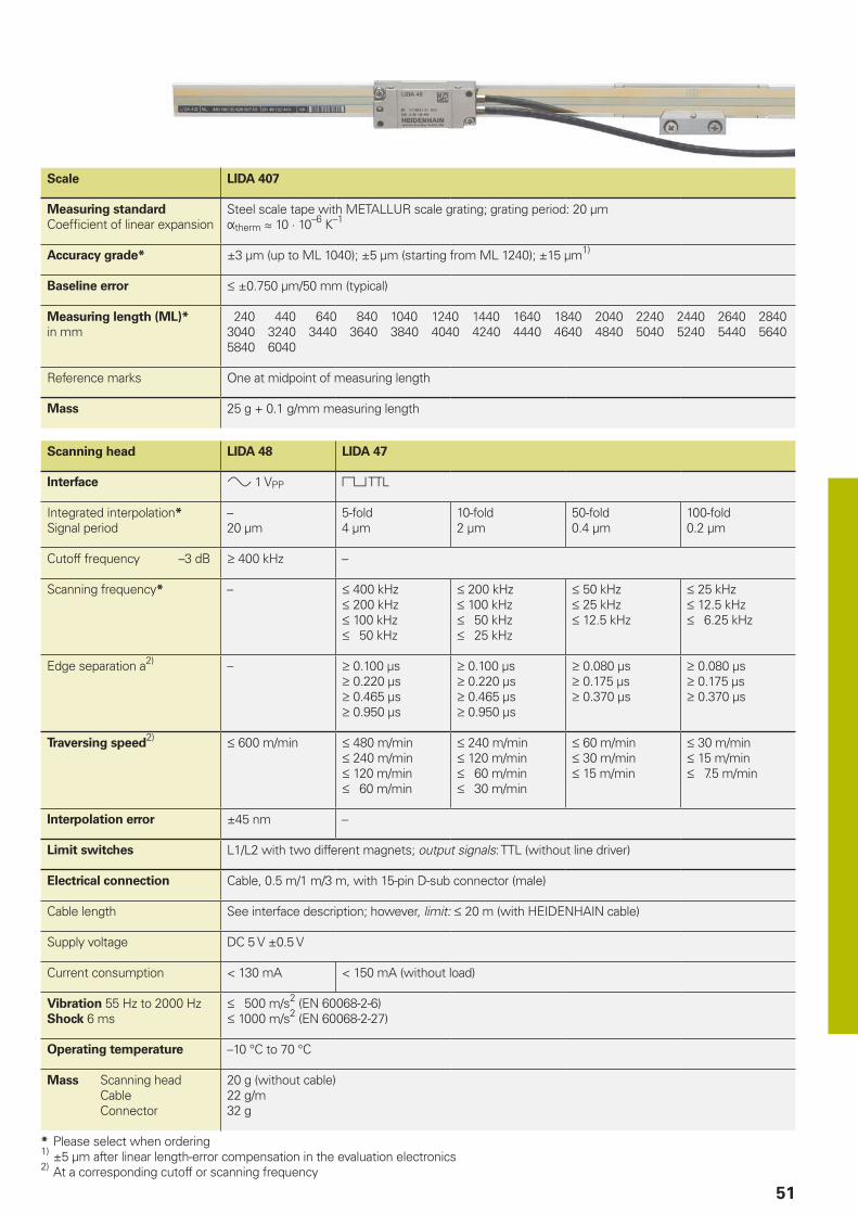
51
Scale LIDA 407
Measuring standardCoefficient of linear expansion
Steel scale tape with METALLUR scale grating; grating period: 20 µmÞtherm � 10 · 10–6 K–1
Accuracy grade* ±3 µm (up to ML 1040); ±5 µm (starting from ML 1240); ±15 µm1)
Baseline error ±0.750 µm/50 mm (typical)
Measuring length (ML)* in mm
240 440 640 840 1040 1240 1440 1640 1840 2040 2240 2440 2640 28403040 3240 3440 3640 3840 4040 4240 4440 4640 4840 5040 5240 5440 56405840 6040
Reference marks One at midpoint of measuring length
Mass 25 g + 0.1 g/mm measuring length
Scanning head LIDA 48 LIDA 47
Interface » 1 VPP « TTL
Integrated interpolation*Signal period
–20 µm
5-fold4 µm
10-fold2 µm
50-fold0.4 µm
100-fold0.2 µm
Cutoff frequency –3 dB 400 kHz –
Scanning frequency* – 400 kHz 200 kHz 100 kHz 50 kHz
200 kHz 100 kHz 50 kHz 25 kHz
50 kHz 25 kHz 12.5 kHz
25 kHz 12.5 kHz 6.25 kHz
Edge separation a2) – 0.100 µs 0.220 µs 0.465 µs 0.950 µs
0.100 µs 0.220 µs 0.465 µs 0.950 µs
0.080 µs 0.175 µs 0.370 µs
0.080 µs 0.175 µs 0.370 µs
Traversing speed2) 600 m/min 480 m/min 240 m/min 120 m/min 60 m/min
240 m/min 120 m/min 60 m/min 30 m/min
60 m/min 30 m/min 15 m/min
30 m/min 15 m/min 7.5 m/min
Interpolation error ±45 nm –
Limit switches L1/L2 with two different magnets; output signals: TTL (without line driver)
Electrical connection Cable, 0.5 m/1 m/3 m, with 15-pin D-sub connector (male)
Cable length See interface description; however, limit: 20 m (with HEIDENHAIN cable)
Supply voltage DC 5 V ±0.5 V
Current consumption < 130 mA < 150 mA (without load)
Vibration 55 Hz to 2000 HzShock 6 ms
500 m/s2 (EN 60068-2-6) 1000 m/s2 (EN 60068-2-27)
Operating temperature –10 °C to 70 °C
Mass Scanning head Cable Connector
20 g (without cable)22 g/m32 g
* Please select when ordering1) ±5 µm after linear length-error compensation in the evaluation electronics2) At a corresponding cutoff or scanning frequency

52
F = Machine guideway* = Maximum change during operation
(IKS: incremental track, RI: reference mark track)Ⓢ = Beginning of measuring length (ML)Ⓡ = Reference mark positionⓁ = Scale tape lengthⒶ = Selector magnet for limit switchⓂ = Mounting surface for scanning head1 = Function indicator2 = Scanning gap3 = Scale-tape stop surface4 = Direction of motion of the scanning unit for ascending position values
LIDA 479, LIDA 489Incremental linear encoders for measuring ranges of up to 6 m• For measuring steps of down to 10 nm• Limit switches• Steel scale tape adhesively bonded to mounting surface• Consists of a scale tape and scanning head
Mounting possibilities for scanning head

53
Scale LIDA 409
Measuring standardCoefficient of linear expansion
Steel scale tape with METALLUR scale grating; grating period: 20 µmÞtherm � 10 · 10–6 K–1
Accuracy grade* ±3 µm, ±15 µm1)
Baseline error ±0.750 µm/50 mm (typical)
Measuring length (ML)* in mm
70 120 170 220 270 320 370 420 520 620 720 820 920 1020
Scale tape from the roll: 2 m,4 m, 6 m
Reference marks One at midpoint of measuring length Every 50 mm3)
Mass 31 g/m
Scanning head LIDA 48 LIDA 47
Interface » 1 VPP « TTL
Integrated interpolation*Signal period
–20 µm
5-fold4 µm
10-fold2 µm
50-fold0.4 µm
100-fold0.2 µm
Cutoff frequency –3 dB 400 kHz –
Scanning frequency* – 400 kHz 200 kHz 100 kHz 50 kHz
200 kHz 100 kHz 50 kHz 25 kHz
50 kHz 25 kHz 12.5 kHz
25 kHz 12.5 kHz 6.25 kHz
Edge separation a2) – 0.100 µs 0.220 µs 0.465 µs 0.950 µs
0.100 µs 0.220 µs 0.465 µs 0.950 µs
0.080 µs 0.175 µs 0.370 µs
0.080 µs 0.175 µs 0.370 µs
Traversing speed2) 600 m/min 480 m/min 240 m/min 120 m/min 60 m/min
240 m/min 120 m/min 60 m/min 30 m/min
60 m/min 30 m/min 15 m/min
30 m/min 15 m/min 7.5 m/min
Interpolation error ±45 nm –
Limit switches L1/L2 with two different magnets; output signals: TTL (without line driver)
Electrical connection Cable, 0.5 m/1 m/3 m, with 15-pin D-sub connector (male)
Cable length See interface description; however, limit: 20 m (with HEIDENHAIN cable)
Supply voltage DC 5 V ±0.5 V
Current consumption < 130 mA < 150 mA (without load)
Vibration 55 Hz to 2000 HzShock 6 ms
500 m/s2 (EN 60068-2-6) 1000 m/s2 (EN 60068-2-27)
Operating temperature –10 °C to 70 °C
Mass Scanning head Cable Connector
20 g (without cable)22 g/m32 g
* Please select when ordering1) ±5 µm after linear length-error compensation in the evaluation electronics2) At a corresponding cutoff or scanning frequency3) Only one reference mark may be used during operation. Recommended: use the LIDA 4xR special scanning head
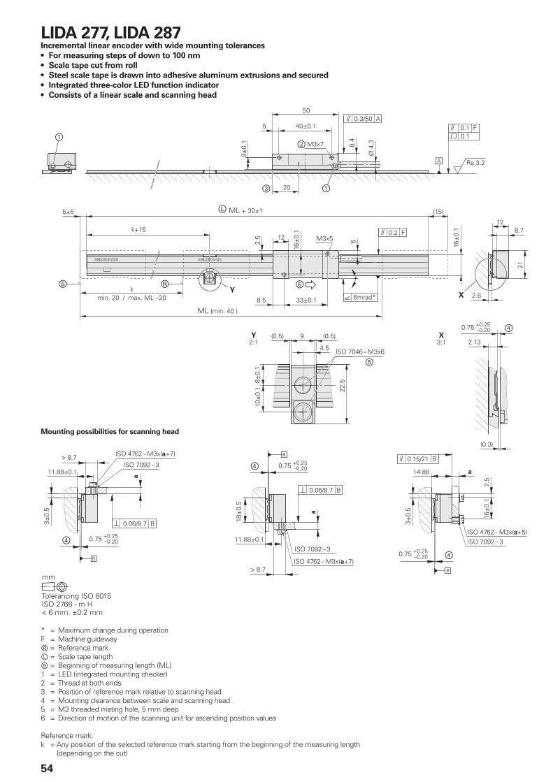
54
* = Maximum change during operationF = Machine guidewayⓇ = Reference markⓁ = Scale tape lengthⓈ = Beginning of measuring length (ML)1 = LED (integrated mounting checker)2 = Thread at both ends3 = Position of reference mark relative to scanning head4 = Mounting clearance between scale and scanning head5 = M3 threaded mating hole, 5 mm deep6 = Direction of motion of the scanning unit for ascending position values
Reference mark:k = Any position of the selected reference mark starting from the beginning of the measuring length
(depending on the cut)
LIDA 277, LIDA 287Incremental linear encoder with wide mounting tolerances• For measuring steps of down to 100 nm• Scale tape cut from roll• Steel scale tape is drawn into adhesive aluminum extrusions and secured• Integrated threecolor LED function indicator• Consists of a linear scale and scanning head
Mounting possibilities for scanning head

55
Scale LIDA 207
Measuring standardCoefficient of linear expansion
Steel scale tape; grating period: 200 µmÞtherm � 10 · 10–6 K–1
Accuracy grade ±15 µm
Scale tape cut from roll* 3 m, 5 m, 10 m
Reference marks Selectable every 100 mm
Mass Scale tape Scale tape carrier
20 g/m70 g/m
Scanning head LIDA 28 LIDA 27
Interface » 1 VPP « TTL
Integrated interpolation*Signal period
–200 µm
10-fold20 µm
50-fold4 µm
100-fold2 µm
Cut-off frequencyScanning frequencyEdge separation a
50 kHz––
– 50 kHz 0.465 µs
– 25 kHz 0.175 µs
– 12.5 kHz 0.175 µs
Traversing speed 600 m/min 300 m/min 150 m/min
Interpolation error ±2 µm –
Electrical connection* Cable, 1 m or 3 m, with 15-pin D-sub connector (male)
Cable length See the interface description; however, 30 m (with HEIDENHAIN cable)
Supply voltage DC 5 V ±0.25 V
Current consumption < 155 mA < 140 mA (without load)
Vibration 55 Hz to 2000 HzShock 11 ms
200 m/s2 (EN 60068-2-6) 500 m/s2 (EN 60068-2-27)
Operating temperature –10 °C to 70 °C
Mass Scanning head Cable Connector
20 g (without cable)30 g/m32 g
* Please select when ordering

56
LIDA 279, LIDA 289Incremental linear encoder with wide mounting tolerances• For measuring steps of down to 100 nm• Scale tape cut from roll• Steel scale tape adhesively bonded to mounting surface• Integrated threecolor LED function indicator• Consists of a linear scale and scanning head
Mounting possibilities for scanning head
* = Maximum change during operationF = Machine guidewayⓇ = Reference markⓁ = Scale tape lengthⓈ = Beginning of measuring length (ML)1 = LED (integrated mounting checker)2 = Thread at both ends3 = Position of reference mark relative to scanning head4 = Adhesive tape5 = Steel scale tape6 = Mounting clearance between scale and scanning head7 = Direction of motion of the scanning unit for ascending position values
Reference mark:k = Any position of the selected reference mark starting from the beginning of the measuring
length (depending on the cut)j = Additional reference marks spaced every n x 100 mm

57
Scale LIDA 209
Measuring standardCoefficient of linear expansion
Steel scale tape; grating period: 200 µmÞtherm � 10 · 10–6 K–1
Accuracy grade ±15 µm
Scale tape cut from roll* 3 m, 5 m, 10 m
Reference marks Selectable every 100 mm
Mass 20 g/m
Scanning head LIDA 28 LIDA 27
Interface » 1 VPP « TTL
Integrated interpolation*Signal period
–200 µm
10-fold20 µm
50-fold4 µm
100-fold2 µm
Cut-off frequencyScanning frequencyEdge separation a
50 kHz––
– 50 kHz 0.465 µs
– 25 kHz 0.175 µs
– 12.5 kHz 0.175 µs
Traversing speed 600 m/min 300 m/min 150 m/min
Interpolation error ±2 µm –
Electrical connection* Cable, 1 m or 3 m, with 15-pin D-sub connector (male)
Cable length See the interface description; however, 30 m (with HEIDENHAIN cable)
Supply voltage DC 5 V ±0.25 V
Current consumption < 155 mA < 140 mA (without load)
Vibration 55 Hz to 2000 HzShock 11 ms
200 m/s2 (EN 60068-2-6) 500 m/s2 (EN 60068-2-27)
Operating temperature –10 °C to 70 °C
Mass Scanning head Cable Connector
20 g (without cable)30 g/m32 g
* Please select when ordering

③
③
①
②
58
PP 281 RTwocoordinate incremental encoder • For measuring steps of 1 µm to 0.05 µm
* = Maximum change during operationF = Machine guidewayⓇ = Reference-mark position relative to center position shown1 = Adjusted during mounting2 = Graduation side3 = Direction of motion of the scanning unit for ascending position values

59
PP 281 R
Measuring standardCoefficient of linear expansion
Two-coordinate TITANID phase grating on glass; grating period: 8 µmÞtherm � 8 · 10–6 K–1
Accuracy grade ±2 µm
Measuring area 68 mm x 68 mm, other measuring areas upon request
Reference marks1) One reference mark in each axis, 3 mm after beginning of measuring length
Interface » 1 VPP
Signal period 4 µm
Cutoff frequency –3 dB 300 kHz
Traversing speed 72 m/min
Interpolation errorRMS position noise
±12 nm3)
2 nm (450 kHz2))
Electrical connection Cable, 0.5 m, with 15-pin D-sub connector (male); interface electronics in the connector
Cable length See the interface description; however, 30 m (with HEIDENHAIN cable)
Supply voltage DC 5 V ±0.25 V
Current consumption < 185 mA per axis
Vibration 55 Hz to 2000 HzShock 11 ms
80 m/s2 (EN 60068-2-6) 100 m/s2 (EN 60068-2-27)
Operating temperature 0 °C to 50 °C
Mass Scanning head Grid plate Connecting cable Connector
170 g (without cable)75 g37 g/m140 g
1) The reference mark signal deviates from the interface specification in its zero crossovers K, L (see the mounting instructions)2) –3 dB cutoff frequency of the subsequent electronics3) With HEIDENHAIN interface electronics (e.g., EIB 741)

60
Interfaces» 1 VPP incremental signals
HEIDENHAIN encoders with the » 1 VPP interface provide voltage signals that can be highly interpolated.
The sinusoidal incremental signals A and B are phase-shifted by 90° elec. and have a typical amplitude of 1 VPP. The illustrated sequence of output signals—with B lagging A—applies to the direction of motion shown in the dimension drawing.
The reference mark signal R has an unambiguous assignment to the incremental signals. The output signal might be somewhat lower next to the reference mark.
« TTL incremental signals
HEIDENHAIN encoders with the « TTL interface incorporate electronics that digitalize sinusoidal scanning signals with or without interpolation.
The incremental signals are transmitted as the square-wave pulse trains Ua1 and Ua2, phase-shifted by 90° elec. The reference mark signal consists of one or more reference pulses Ua0, which are gated with the incremental signals. In addition, the integrated electronics produce their inverted signals ¢, £, and ¤ for noise-proof transmission. The illustrated sequence of output signals—with Ua2 lagging Ua1—applies to the direction of motion shown in the dimension drawing.
Signal period 360° elec. Fault
Measuring step after 4fold evaluation
The inverted signals ¢, £, ¤ are not shown
Signal period360° elec.
(rated value)
A, B, R measured with oscilloscope in differential mode
Alternative signal shape
Further information:
For detailed descriptions of all available interfaces, as well as general electrical information, please refer to the Interfaces of HEIDENHAIN Encoders brochure.
Further information:
For detailed descriptions of all available interfaces, as well as general electrical information, please refer to the Interfaces of HEIDENHAIN Encoders brochure.
The fault detection signal ¥ indicates fault conditions such as an interruption in the supply lines, failure of the light source, etc.
The distance between two successive edges of the incremental signals Ua1 and Ua2 through 1-fold, 2-fold, or 4-fold evaluation is one measuring step.

61
Limit switches
LIDA 400 encoders are equipped with two limit switches that enable limit-position detection and the formation of homing tracks. The limit switches are activated by differing adhesive magnets to enable switching between the left or right limit. The magnets can be configured in series to set up homing tracks. The signals from the limit switches L1 and L2 are transmitted over separate lines and are therefore directly available. Nevertheless, the cable has only a very thin diameter of 3.7 mm in order to keep the forces on movable machine elements to a minimum.
The incremental signals conform with the 1 VPP or TTL interface.
Further information:
For detailed descriptions of all available interfaces, as well as general electrical information, please refer to the Interfaces of HEIDENHAIN Encoders brochure.
Position detection
Besides the incremental graduation, the LIF 4x1 and LIP 60x1 encoders feature a homing track and limit switches for limit position detection.
The signals for position detection H and L are transmitted at the TTL level over the separate lines H and L and are therefore directly available. Yet the cable has only a very thin diameter of 4.5 mm (LIF 4x1) or 3.7 mm (LIP 60x1) in order to keep the forces on movable machine elements to a minimum.
The incremental signals conform with the 1 VPP or TTL interface.
Further information:
For detailed descriptions of all available interfaces, as well as general electrical information, please refer to the Interfaces of HEIDENHAIN Encoders brochure.

2)
2)
62
LIDA15pin Dsub connector
Power supply Incremental signals Other signals
4 12 2 10 1 9 3 11 14 7 13 8 6 15 5
« TTL UP Sensor4)
5 V
0 V Sensor4)
0 V
Ua1 ¢ Ua2 £ Ua0 ¥ L13) L23) PWT1) Vacant
» 1 VPP A+ A– B+ B– R+ R– Assigned
Assigned
Vacant
Brown/Green
Blue White/Green
White Brown Green Gray Pink Red Black Violet Green/Black
Yellow/Black
Yellow /
Shield on housing; UP = Power supply voltageSensor: The sense line is connected in the encoder with the corresponding
power line.Unused pins or wires must not be assigned!
1) TTL/11 µAPP conversion for the PWT2) Color assignment of the connecting cable3) Valid only for the LIDA 4004) LIDA 200: vacant
LIF and LIP 600015pin Dsub connector
Power supply Incremental signals Other signals
4 12 2 10 1 9 3 11 14 7 13 8 6 15 5
« TTL UP Sensor5 V
0 V Sensor0 V
Ua1 ¢ Ua2 £ Ua0 ¥ H3) L3) PWT1) Vacant
» 1 VPP A+ A– B+ B– R+ R– Assigned
Assigned
Vacant
Brown/Green
Blue White/Green
White Brown Green Gray Pink Red Black Violet Green/Black
Green/Black
Yellow /
Shield on housing; UP = Power supply voltageSensor: The sense line is connected in the encoder with the corresponding
power line.Unused pins or wires must not be assigned!
1) TTL/11 µAPP conversion for the PWT2) Color assignment of the connecting cable3) Valid only for the LIP 6000/LIF 400
InterfacesPin layouts (1 VPP/TTL)
Further information:
For detailed descriptions of cables, please refer to the Cables and Connectors brochure.
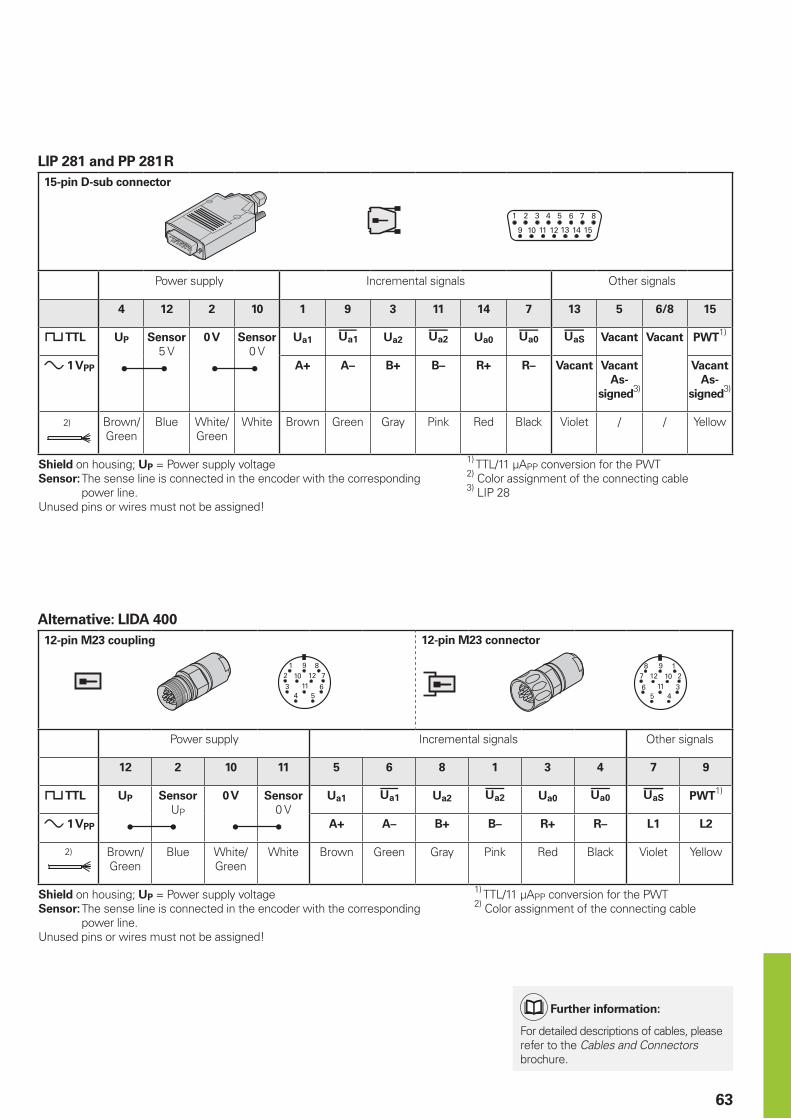
2)
2)
63
LIP 281 and PP 281 R15pin Dsub connector
Power supply Incremental signals Other signals
4 12 2 10 1 9 3 11 14 7 13 5 6/8 15
« TTL UP Sensor5 V
0 V Sensor0 V
Ua1 ¢ Ua2 £ Ua0 ¥ Vacant Vacant PWT1)
» 1 VPP A+ A– B+ B– R+ R– Vacant VacantAs
signed3)
VacantAs
signed3)
Brown/Green
Blue White/Green
White Brown Green Gray Pink Red Black Violet / / Yellow
Shield on housing; UP = Power supply voltageSensor: The sense line is connected in the encoder with the corresponding
power line.Unused pins or wires must not be assigned!
1) TTL/11 µAPP conversion for the PWT2) Color assignment of the connecting cable3) LIP 28
Alternative: LIDA 40012pin M23 coupling 12pin M23 connector
Power supply Incremental signals Other signals
12 2 10 11 5 6 8 1 3 4 7 9
« TTL UP SensorUP
0 V Sensor0 V
Ua1 ¢ Ua2 £ Ua0 ¥ PWT1)
» 1 VPP A+ A– B+ B– R+ R– L1 L2
Brown/Green
Blue White/Green
White Brown Green Gray Pink Red Black Violet Yellow
Shield on housing; UP = Power supply voltageSensor: The sense line is connected in the encoder with the corresponding
power line.Unused pins or wires must not be assigned!
1) TTL/11 µAPP conversion for the PWT2) Color assignment of the connecting cable
Further information:
For detailed descriptions of cables, please refer to the Cables and Connectors brochure.

64
Interfaces position values
The EnDat interface is a digital, bidirectional interface for encoders. It is capable of outputting position values, reading and updating information stored in the encoder, and storing new information in the encoder. Thanks to the serial transmission method, only four signal lines are required. The DATA data are transmitted in synchronism with the CLOCK signal from the subsequent electronics. The type of transmission (position values, parameters, diagnostics, etc.) is selected via mode commands sent to the encoder by the subsequent electronics. Some functions are available only with EnDat 2.2 mode commands.
Ordering designation Command set Incremental signals
EnDat01 EnDat 2.1 or EnDat 2.2 With
EnDat21 Without
EnDat02 EnDat 2.2 With
EnDat22 EnDat 2.2 Without
Versions of the EnDat interface
Absolute encoder Subsequent electronics
» 1 VPP A*)
» 1 VPP B*)
Operating parameters
Operating status
Parameters of the OEM
Parameters of the encoder manufacturer for
EnDat 2.1 EnDat 2.2
*) Depending on the device
Absolute position value En
Dat
inte
rfac
e
Incremental signals *)
EnDat pin layout8pin M12 coupling 15pin Dsub connector
Power supply Serial data transfer
8 2 5 1 3 4 7 6
4 12 2 10 5 13 8 15
UP SensorUP
0 V Sensor0 V
DATA DATA CLOCK CLOCK
Brown/Green Blue White/Green White Gray Pink Violet Yellow
Cable shield connected to housing; UP = Power supply voltageSensor: The sense line is connected in the encoder with the corresponding power line.Unused pins or wires must not be assigned!
Further information:
For detailed descriptions of all available interfaces, as well as general electrical information, please refer to the Interfaces of HEIDENHAIN Encoders brochure.
Further information:
For detailed descriptions of cables, please refer to the Cables and Connectors brochure.

65
Fanuc pin layoutHEIDENHAIN encoders with the code letter F following the model designation are suitable for connection to Fanuc controls and drive systems.
Fanuc and Mitsubishi pin layouts
Mitsubishi pin layoutHEIDENHAIN encoders with the code letter M following the model designation are suitable for connection to Mitsubishi controls and drive systems.
Fanuc Serial Interface – i Interface Ordering designation: Fanuc05 high speed, one-pair transmission contains the Þ interface (normal and high speed, two-pair transmission)
Mitsubishi high speed interface• Ordering designation: Mitsu01
two-pair transmission• Ordering designation: Mit02-4
Generation 1, two-pair transmission
Mitsubishi pin layout8pin M12 coupling 15pin Dsub connector
Power supply Serial data transfer
8 2 5 1 3 4 7 6
4 12 2 10 5 13 8 15
Mit034 UP SensorUP
0 V Sensor0 V
Serial Data Serial Data RequestFrame
RequestFrame
Mit022 Vacant Vacant Request/Data
Request/Data
Brown/Green Blue White/Green White Gray Pink Violet Yellow
Cable shield connected to housing; UP = Power supply voltageSensor: The sense line is connected in the encoder with the corresponding power line.Unused pins or wires must not be assigned!
Fanuc pin layout8pin M12 coupling 15pin Dsub connector
Power supply Serial data transfer
8 2 5 1 3 4 7 6
4 12 2 10 5 13 8 15
UP SensorUP
0 V Sensor0 V
Serial Data Serial Data Request Request
Brown/Green Blue White/Green White Gray Pink Violet Yellow
Cable shield connected to housing; UP = Power supply voltageSensor: The sense line is connected in the encoder with the corresponding power line.Unused pins or wires must not be assigned!
• Ordering designation: Mit02-2 Generation 1, one-pair transmission
• Ordering designation: Mit03-4 Generation 2, two-pair transmission
Further information:
For detailed descriptions of cables, please refer to the Cables and Connectors brochure.

66
Panasonic pin layoutHEIDENHAIN encoders with the code letter P following the model designation are suitable for connection to Panasonic controls and drive systems.
• Ordering designation: Pana01
Panasonic pin layout8pin M12 coupling 15pin Dsub connector
Power supply Serial data transfer
8 2 5 1 3 4 7 6
4 12 2 10 5 13 8 15
UP SensorUP
0 V Sensor0 V
Vacant1) Vacant1) RequestData
RequestData
Brown/Green Blue White/Green White Gray Pink Violet Yellow
Cable shield connected to housing; UP = Power supply voltageSensor: The sense line is connected in the encoder with the corresponding power line.Unused pins or wires must not be assigned!1) Required for adjustment/testing with the PWM 21
Further information:
For detailed descriptions of cables, please refer to the Cables and Connectors brochure.
Panasonic and Yaskawa pin layouts
Yaskawa pin layoutHEIDENHAIN encoders with the code letter F following the model designation are suitable for connection to Yaskawa controls and drive systems.
• Ordering designation: YEC07
Yaskawa pin layout8pin M12 coupling 15pin Dsub connector
Power supply Serial data transfer
8 2 5 1 3 4 7 6
4 12 2 10 5 13 8 15
UP SensorUP
0 V Sensor0 V
Vacant1) Vacant1) Data Data
Brown/Green Blue White/Green White Gray Pink Violet Yellow
Cable shield connected to housing; UP = Power supply voltageSensor: The sense line is connected in the encoder with the corresponding power line.Unused pins or wires must not be assigned!1) Required for adjustment/testing with the PWM 21
Further information:
For detailed descriptions of cables, please refer to the Cables and Connectors brochure.

67
Testing equipment and diagnostics
Diagnostics in the control loop on HEIDENHAIN controls with display of the valuation number or the analog encoder signals
Diagnostics via the PWM 21 and ATS software
Commissioning via the PWM 21 and ATS software
HEIDENHAIN encoders provide all of the information necessary for commissioning, monitoring, and diagnostics. The type of information available depends on whether the encoder is incremental or absolute and on which interface is used.
Incremental encoders mainly have 1 VPP, TTL, or HTL interfaces. TTL and HTL encoders monitor their signal amplitudes internally and generate a single fault detection signal. With 1 VPP signals, the analysis of output signals is possible only with external testing devices or via computation in the subsequent electronics (analog diagnostics interface).
Absolute encoders use serial data transmis-sion. Depending on the interface, additional 1 VPP incremental signals can be output. The signals are comprehensively monitored within the encoder. The monitoring result (particularly in the case of valuation numbers) can be transmitted to the sub sequent electronics along with the position values via the serial interface (digital diagnostics interface). The following information is available:• Error message: position value is not
reliable.• Warning: An internal functional limit of
the encoder has been reached.• Valuation numbers:
– Detailed information on the encoder’s functional reserve
– Identical scaling for all HEIDENHAIN encoders
– Cyclic reading is possibleThis enables the subsequent electronics to evaluate the current status of the encoder with little effort, even in closed-loop mode.
HEIDENHAIN offers the appropriate PWM inspection devices and PWT testing devices for encoder analysis. Depending on how these devices are integrated, a differentiation is made between two types of diagnostics:• Encoder diagnostics: the encoder is
connected directly to the testing or inspection device. This makes a detailed analysis of encoder functions possible.
• Diagnostics in the control loop: The PWM testing unit is linked into the closed control loop (e.g., via a suitable testing adapter). This enables real-time diagnosis of the machine or system during operation. The available functions depend on the interface.

68
Testing equipment and diagnostics
PWM 21The PWM 21 phase-angle measuring unit, together with the ATS adjusting and testing software, serves as an adjusting testing package for the diagnosis and adjustment of HEIDENHAIN encoders.
PWM 21
Encoder input • EnDat 2.1 or EnDat 2.2 (absolute value with or without incremental signals)
• DRIVE-CLiQ• Fanuc Serial Interface• Mitsubishi high speed interface• Yaskawa Serial Interface• SSI• 1 VPP/TTL/11 µAPP
Interface USB 2.0
Supply voltage AC 100 V to 240 V or DC 24 V
Dimensions 258 mm x 154 mm x 55 mm
ATS
Languages Choice between English and German
Functions • Position display• Connection dialog• Diagnostics• Mounting wizard for the EBI/ECI/EQI, LIP 200, LIC 4100
and others• Additional functions (if supported by the encoder)• Memory contents
System requirements and recommendations
PC (dual-core processor > 2 GHz)RAM > 2 GBOperating system: Windows XP, Vista, 7 (32-bit/64-bit), 8, 10200 MB of free hard disk space
DRIVE-CLiQ is a registered trademark of Siemens AG
For more information, see the PWM 21/ATS Software Product Information document.
PWT 100The PWT 100 is a testing device for the functional testing and adjustment of incremental and absolute HEIDENHAIN encoders. Thanks to its compact dimensions and robust design, the PWT 100 is ideal for portable use.
PWT 100
Encoder inputOnly for HEIDENHAIN encoders
• EnDat• Fanuc Serial Interface• Mitsubishi high speed interface• Panasonic Serial Interface• Yaskawa Serial Interface• 1 VPP with Z1 track• 1 VPP• 11 µAPP• TTL
Display 4.3-inch touchscreen
Supply voltage DC 24 VPower consumption: max. 15 W
Operating temperature 0 °C to 40 °C
Protection EN 60529 IP20
Dimensions � 145 mm x 85 mm x 35 mm
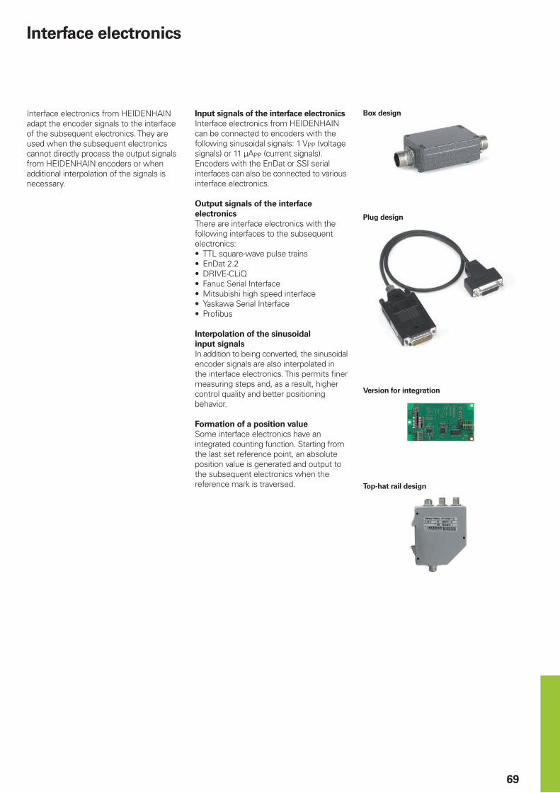
69
Interface electronics
Interface electronics from HEIDENHAIN adapt the encoder signals to the interface of the subsequent electronics. They are used when the subsequent electronics cannot directly process the output signals from HEIDENHAIN encoders or when additional interpolation of the signals is necessary.
Box design
Version for integration
Tophat rail design
Input signals of the interface electronicsInterface electronics from HEIDENHAIN can be connected to encoders with the following sinusoidal signals: 1 VPP (voltage signals) or 11 µAPP (current signals). Encoders with the EnDat or SSI serial interfaces can also be connected to various interface electronics.
Output signals of the interface electronicsThere are interface electronics with the following interfaces to the subsequent electronics:• TTL square-wave pulse trains• EnDat 2.2• DRIVE-CLiQ• Fanuc Serial Interface• Mitsubishi high speed interface• Yaskawa Serial Interface• Profibus
Interpolation of the sinusoidal input signalsIn addition to being converted, the sinusoidal encoder signals are also interpolated in the interface electronics. This permits finer measuring steps and, as a result, higher control quality and better positioning behavior.
Formation of a position valueSome interface electronics have an integrated counting function. Starting from the last set reference point, an absolute position value is generated and output to the subsequent electronics when the reference mark is traversed.
Plug design

70
Outputs Inputs Design – degree of protection
Interpolation1) or subdivision Model
Interface Quantity Interface Quantity
« TTL 1 » 1 VPP 1 Box design – IP65 5/10-fold IBV 101
20/25/50/100-fold IBV 102
Without interpolation IBV 600
25/50/100/200/400-fold IBV 660 B
Plug design – IP40 5/10/20/25/50/100-fold APE 371
Version for integration – IP00
5/10-fold IDP 181
20/25/50/100-fold IDP 182
» 11 µAPP 1 Box design – IP65 5/10-fold EXE 101
20/25/50/100-fold EXE 102
Version for integration – IP00
5-fold IDP 101
« TTL/ » 1 VPPAdjustable
2 » 1 VPP 1 Box design – IP65 2-fold IBV 6072
5/10-fold IBV 6172
5/10-fold and 20/25/50/100-fold IBV 6272
EnDat 2.2 1 » 1 VPP 1 Box design – IP65 16384-fold subdivision EIB 192
Plug design – IP40 16384-fold subdivision EIB 392
2 Box design – IP65 16384-fold subdivision EIB 1512
DRIVE-CLiQ 1 EnDat 2.2 1 Box design – IP65 – EIB 2391 S
Fanuc Serial Interface
1 » 1 VPP 1 Box design – IP65 16384-fold subdivision EIB 192 F
Plug design – IP40 16384-fold subdivision EIB 392 F
2 Box design – IP65 16384-fold subdivision EIB 1592 F
Mitsubishi high speed interface
1 » 1 VPP 1 Box design – IP65 16384-fold subdivision EIB 192 M
Plug design – IP40 16384-fold subdivision EIB 392 M
2 Box design – IP65 16384-fold subdivision EIB 1592 M
Yaskawa Serial Interface
1 EnDat 2.22) 1 Plug design – IP40 – EIB 3391 Y
PROFIBUS DP 1 EnDat 2.1; EnDat 2.2 1 Top-hat rail design – PROFIBUS Gateway
1) Switchable2) Only for the LIC 4100 with a 5 nm measuring step, or the LIC 2100 with a 50 nm or 100 nm measuring step

PH MACHINEBANKS' CORPORATIONQuezon City, Philippines 1113 E-mail: [email protected]
PL APS02-384 Warszawa, Poland www.heidenhain.pl
PT FARRESA ELECTRÓNICA, LDA.4470 - 177 Maia, Portugal www.farresa.pt
RO HEIDENHAIN Reprezentanta RomaniaBrasov, 500407, Romania www.heidenhain.ro
RS Serbia BG
RU OOO HEIDENHAIN115172 Moscow, Russia www.heidenhain.ru
SE HEIDENHAIN Scandinavia AB12739 Skärholmen, Sweden www.heidenhain.se
SG HEIDENHAIN PACIFIC PTE LTDSingapore 408593 www.heidenhain.com.sg
SK KOPRETINA TN s.r.o.91101 Trencin, Slovakia www.kopretina.sk
SL NAVO d.o.o.2000 Maribor, Slovenia www.heidenhain.si
TH HEIDENHAIN (THAILAND) LTDBangkok 10250, Thailand www.heidenhain.co.th
TR T&M Mühendislik San. ve Tic. LTD. STI·.
34775 Y. Dudullu – Ümraniye-Istanbul, Turkey www.heidenhain.com.tr
TW HEIDENHAIN Co., Ltd.Taichung 40768, Taiwan R.O.C. www.heidenhain.com.tw
UA Gertner Service GmbH Büro Kiev 02094 Kiev, Ukraine www.heidenhain.ua
US HEIDENHAIN CORPORATIONSchaumburg, IL 60173-5337, USA www.heidenhain.com
VN AMS Co. LtdHCM City, VietnamE-mail: [email protected]
ZA MAFEMA SALES SERVICES C.C.Midrand 1685, South Africa www.heidenhain.co.za
ES FARRESA ELECTRONICA S.A.08028 Barcelona, Spain www.farresa.es
FI HEIDENHAIN Scandinavia AB01740 Vantaa, Finland www.heidenhain.fi
FR HEIDENHAIN FRANCE sarl92310 Sèvres, France www.heidenhain.fr
GB HEIDENHAIN (G.B.) LimitedBurgess Hill RH15 9RD, United Kingdom www.heidenhain.co.uk
GR MB Milionis Vassilis17341 Athens, Greece www.heidenhain.gr
HK HEIDENHAIN LTDKowloon, Hong Kong E-mail: [email protected]
HR Croatia SL
HU HEIDENHAIN Kereskedelmi Képviselet1239 Budapest, Hungary www.heidenhain.hu
ID PT Servitama Era ToolsindoJakarta 13930, Indonesia E-mail: [email protected]
IL NEUMO VARGUS MARKETING LTD.Holon, 58859, Israel E-mail: [email protected]
IN HEIDENHAIN Optics & Electronics India Private LimitedChetpet, Chennai 600 031, India www.heidenhain.in
IT HEIDENHAIN ITALIANA S.r.l.20128 Milano, Italy www.heidenhain.it
JP HEIDENHAIN K.K.Tokyo 102-0083, Japan www.heidenhain.co.jp
KR HEIDENHAIN Korea LTD.Gasan-Dong, Seoul, Korea 153-782 www.heidenhain.co.kr
MX HEIDENHAIN CORPORATION MEXICO20290 Aguascalientes, AGS., Mexico E-mail: [email protected]
MY ISOSERVE SDN. BHD.43200 Balakong, Selangor E-mail: [email protected]
NL HEIDENHAIN NEDERLAND B.V.6716 BM Ede, Netherlands www.heidenhain.nl
NO HEIDENHAIN Scandinavia AB7300 Orkanger, Norway www.heidenhain.no
NZ Llama ENGINEERING Ltd5012 Wellington, New Zealand E-mail: [email protected]
AR NAKASE SRL.B1653AOX Villa Ballester, Argentina www.heidenhain.com.ar
AT HEIDENHAIN Techn. Büro Österreich83301 Traunreut, Germany www.heidenhain.de
AU FCR MOTION TECHNOLOGY PTY LTDLaverton North Victoria 3026, Australia E-mail: [email protected]
BE HEIDENHAIN N.V.1760 Roosdaal, Belgium www.heidenhain.be
BG ESD Bulgaria Ltd.Sofia 1172, Bulgaria www.esd.bg
BR HEIDENHAIN Brasil Ltda.04763-070 – São Paulo – SP, Brazil www.heidenhain.com.br
BY GERTNER Service GmbH220026 Minsk, Belarus www.heidenhain.by
CA HEIDENHAIN CORPORATIONMississauga, OntarioL5T2N2, Canada www.heidenhain.com
CH HEIDENHAIN (SCHWEIZ) AG8603 Schwerzenbach, Switzerland www.heidenhain.ch
CN DR. JOHANNES HEIDENHAIN (CHINA) Co., Ltd.Beijing 101312, China www.heidenhain.com.cn
CZ HEIDENHAIN s.r.o.102 00 Praha 10, Czech Republic www.heidenhain.cz
DK TP TEKNIK A/S2670 Greve, Denmark www.tp-gruppen.dk
DE HEIDENHAIN Vertrieb Deutschland83301 Traunreut, Deutschland 08669 31-3132| 08669 32-3132E-Mail: [email protected]
HEIDENHAIN Technisches Büro Nord12681 Berlin, Deutschland 030 54705-240
HEIDENHAIN Technisches Büro Mitte07751 Jena, Deutschland 03641 4728-250
HEIDENHAIN Technisches Büro West44379 Dortmund, Deutschland 0231 618083-0
HEIDENHAIN Technisches Büro Südwest70771 Leinfelden-Echterdingen, Deutschland 0711 993395-0
HEIDENHAIN Technisches Büro Südost83301 Traunreut, Deutschland 08669 31-1337
Vollständige und weitere Adressen siehe www.heidenhain.de For complete and further addresses see www.heidenhain.de
����������������������������������������������������������� ���� ���������������� ����������� ��������� �����������������������������
����������������
*I_208960-2F*
208960-2F · 7.5 · 05/2019 · F&W · Printed in Germany