Exporting Civil3D toH EC RAS Ver1.0
26
Creating a quick and accurate floodplain model from a terrain model. HEC RAS: Design Note 1 ver. 1.0 Exporting a Civil 3D surface to HEC-RAS USDA Larson, Mark - NRCS, Huron, SD
-
Upload
ivan-ayala -
Category
Documents
-
view
19 -
download
1
description
Tutorial para exportar datos de CIvil 3D a HecRas
Transcript of Exporting Civil3D toH EC RAS Ver1.0

Creating a quick and accurate floodplain model from a terrain model.
HEC RAS: Design Note 1 ver. 1.0 Exporting a Civil 3D surface to HEC-RAS
USDA Larson, Mark - NRCS, Huron, SD

HEC RAS: DESIGN NOTE 1 VER. 1.0 September 2, 2014
This page intentionally left blank.

September 2, 2014 HEC RAS: DESIGN NOTE 1 VER. 1.0
HEC RAS: Design Note 1 Exporting a Civil 3D surface to HEC RAS.
The following document will instruct the user how to export a Civil 3D surface to HEC RAS.
This document is intended for use by USDA NRCS employees who work with AutoCAD Civil 3D and HEC-RAS when designing engineering practices.
This document presumes the user is familiar with basic operation of the following software; Windows OS, Microsoft Office, AutoCAD Civil 3D, and HEC RAS and can develop a surface using AutoCAD Civil 3D and run a steady or unsteady flow analysis in HEC RAS. This document also presumes the user is using Windows OS 7, Microsoft Office 2010, AutoCAD 2010 Civil 3D 2011, and HEC RAS 4.1.0. Software used in this document is CCE approved at the time of writing and any future updates may change the processes used in this document.
When the instructions say to “click”, this means to use the left mouse button. The instructions will distinguish when the right mouse button or wheel are to be used.
Table of Contents
Prepare Surface for Exporting .................................................................................................... 3
Define Alignment for the Stream Centerline ................................................................................................................ 4
Create Cross Sections .................................................................................................................................................... 9
Create Out-of-Bank Polylines ..................................................................................................................................... 13
Export of data .............................................................................................................................................................. 14
Flipping Coordinates, Method 1 .................................................................................................................................. 17
Open HEC RAS and Create Project ............................................................................................................................ 20
Importing the GEO file ............................................................................................................................................... 22
Flipping Coordinates, Method 2 .................................................................................................................................. 25

HEC RAS: DESIGN NOTE 1 VER. 1.0 September 2, 2014
Prepare Surface for Exporting The following instructions presume that a surface has already been created in AutoCAD Civil 3D.
For these instructions, the example project will be called Juniper. The same surface will be used throughout the example. The following is an image of the Juniper surface to be used in this example.

September 2, 2014 HEC RAS: DESIGN NOTE 1 VER. 1.0 Define Alignment for the Stream Centerline The first thing needed is to find an alignment for the stream center line. In order to do this, create a polyline that begins at the downstream end and finishes at the upstream end of the portion of the stream in question.
IMPORTANT! The polyline must be created beginning with the downstream end and finishing at the upstream end.
STEP 1; Click on the polyline icon to begin a polyline (or type the pline command).
STEP 2; Draw the polyline from the downstream end, to the upstream end of the section of stream to be analyzed.
Note: the polyline is drawn at the thalweg of the stream. Be as detailed as is appropriate for the project and design.
START -DOWNSTREAM
FINISH -UPSTREAM

HEC RAS: DESIGN NOTE 1 VER. 1.0 September 2, 2014
STEP 3; Select the Home option on the ribbon tab, then select Alignment, and then select Create Alignment from Objects (or type the CreateAlignmentEntities command).
Choose the polyline that was just created by clicking on it, and then press [Enter] twice. The first time is to accept the selection, and the second is to accept the alignment direction.

September 2, 2014 HEC RAS: DESIGN NOTE 1 VER. 1.0 The following dialog box will appear.
STEP 4; Enter a name for the alignment. In this example, JuniperCL will be used.
STEP 5; Uncheck the box next to Add curves between tangents. The centerline needs to be left as drawn without curves.
STEP 4
STEP 5

HEC RAS: DESIGN NOTE 1 VER. 1.0 September 2, 2014
The dialog box should now look similar to the following image.
STEP 6; Click on Ok.

September 2, 2014 HEC RAS: DESIGN NOTE 1 VER. 1.0 The alignment has been created and should look similar to the following image.
Note which direction the stations increase. If the stations increase from downstream to upstream, then the alignment is ready for the next process. If not, reverse the direction of the alignment so that the downstream end begins with station 0+00.
HEC RAS: DESIGN NOTE 1 VER. 1.0 September 2, 2014
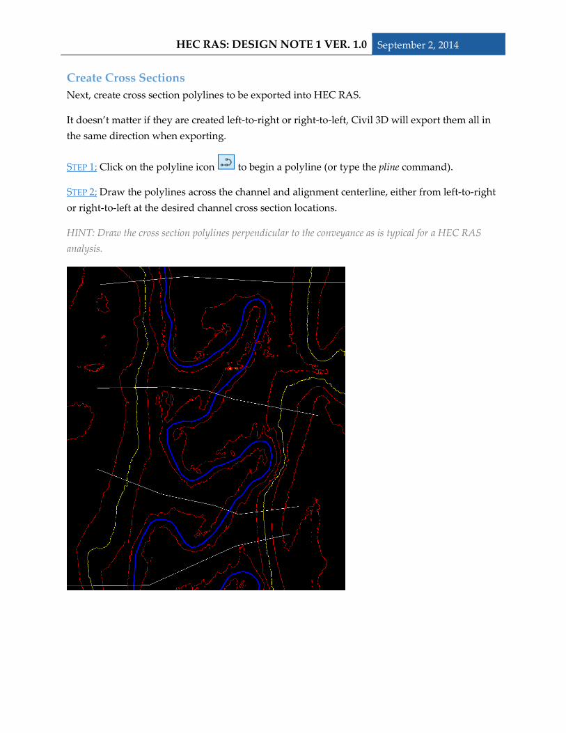
Create Cross Sections Next, create cross section polylines to be exported into HEC RAS.
It doesn’t matter if they are created left-to-right or right-to-left, Civil 3D will export them all in the same direction when exporting.
STEP 1; Click on the polyline icon to begin a polyline (or type the pline command).
STEP 2; Draw the polylines across the channel and alignment centerline, either from left-to-right or right-to-left at the desired channel cross section locations.
HINT: Draw the cross section polylines perpendicular to the conveyance as is typical for a HEC RAS analysis.

September 2, 2014 HEC RAS: DESIGN NOTE 1 VER. 1.0 STEP 3; Select the Home option on the ribbon tab, then select Sample Lines.
In the command line it says Select an alignment <or press enter key to select from list>.
STEP 4; Press [Enter].
The following dialog box will appear.
STEP 5; Click on the created alignment, JuniperCL.
STEP 6; Click on OK.
STEP 5
STEP 6

HEC RAS: DESIGN NOTE 1 VER. 1.0 September 2, 2014
The following dialog boxes will appear.
STEP 7; Enter a name for the Sample Line Group. In this example JuniperXS, for Juniper cross sections, will be used.
STEP 8; Click on OK.
The following editor box for Sample Line Tools will appear.
STEP 9; Click on the dropdown arrow next to the At a Station symbol and click on Select existing polylines.
STEP 7
STEP 8
STEP 9
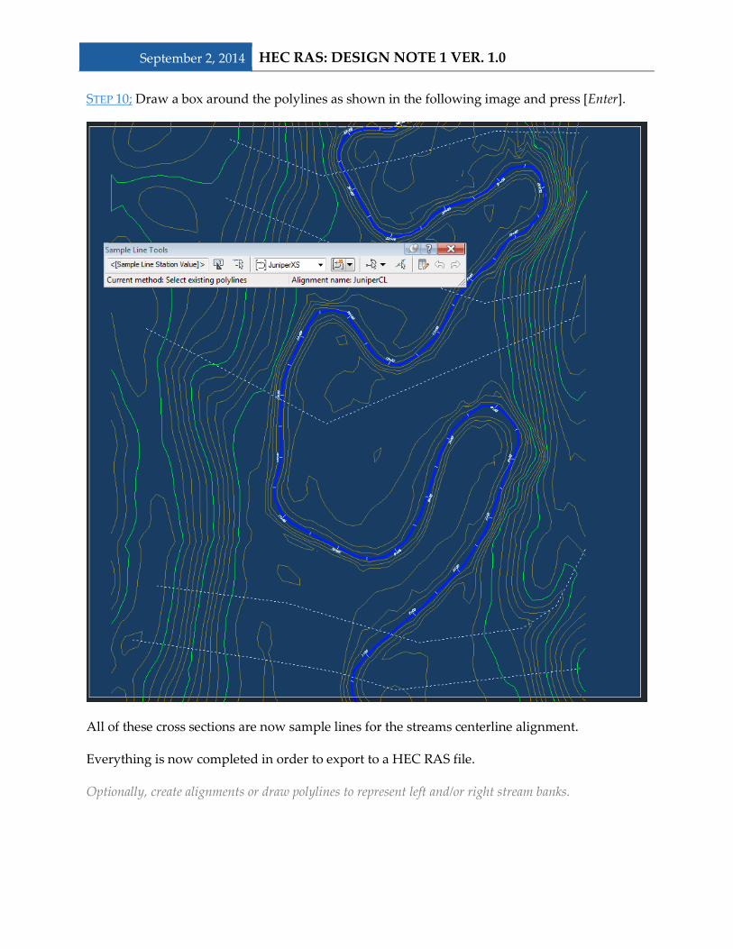
September 2, 2014 HEC RAS: DESIGN NOTE 1 VER. 1.0 STEP 10; Draw a box around the polylines as shown in the following image and press [Enter].
All of these cross sections are now sample lines for the streams centerline alignment.
Everything is now completed in order to export to a HEC RAS file.
Optionally, create alignments or draw polylines to represent left and/or right stream banks.

HEC RAS: DESIGN NOTE 1 VER. 1.0 September 2, 2014
Create Out-of-Bank Polylines This process will create polylines to represent the right and left out-of-bank locations. These lines will be imported into HEC RAS as the right and left river banks.
STEP 1; Click on the polyline icon to begin a polyline (or type the pline command).
STEP 2; Draw the polylines either from downstream-to-upstream or upstream-to-downstream at the desired overbank locations parallel to the alignment centerline.
HINT: Draw the overbank polylines parallel to the conveyance as is typical for a HEC RAS analysis.

September 2, 2014 HEC RAS: DESIGN NOTE 1 VER. 1.0 Export of data This process will place all the information previously developed and place it into a single file to be used by HEC RAS.
STEP 1; Select the Output option on the ribbon tab, then select Export to HEC RAS (or type the ExportHecRas command).
The following dialog box will appear.
STEP 2; Click on the dropdown arrow next to Surface and choose the surface that will be used for the cross section data. In this example, Ognd (1) was used.
STEP 3; Click on the dropdown arrow next to Site and choose <None>.
STEP 4; If the Reach alignment box has not changed to the previously created alignment, click on the dropdown arrow next to Reach alignment and choose the alignment that will be used for the cross section data. In this example, JuniperCL was used.
STEP 7
STEP 6
STEP 5
STEP 4
STEP 3
STEP 2

HEC RAS: DESIGN NOTE 1 VER. 1.0 September 2, 2014
STEP 5; If the Sample line groups box has not changed to the previously created sample line group, click on the dropdown arrow next to Sample line groups and choose the sample line group that will be used for the cross section data. In this example, JuniperXS was used.
STEP 6; Name the river. Give the river a name that meets the naming conventions in HEC-RAS. This River name will be the identifier used in HEC-RAS.
STEP 7; Check the box for River Banks. Check the Left box, and then choose the polyline for the left overbank. This is the left overbank as looking upstream. Check the Right box, and then choose the polyline for the right overbank. This is the right overbank as looking upstream.
The dialog box should now look similar to the following image.
STEP 8; Click on Export.
STEP 7
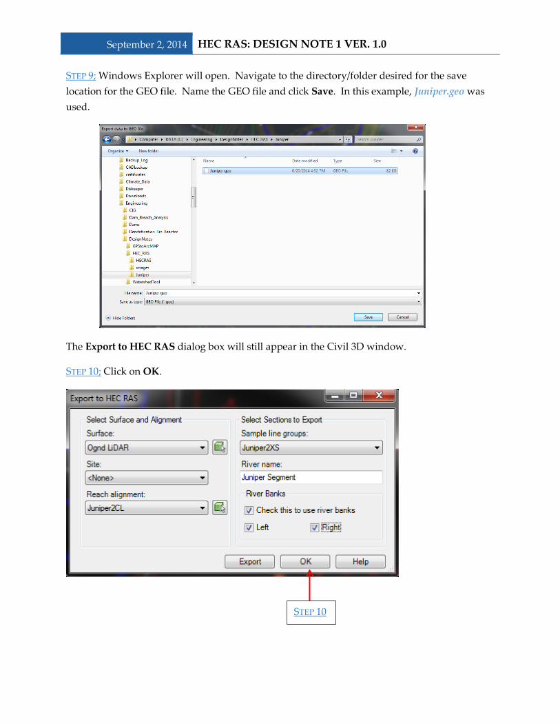
September 2, 2014 HEC RAS: DESIGN NOTE 1 VER. 1.0 STEP 9; Windows Explorer will open. Navigate to the directory/folder desired for the save location for the GEO file. Name the GEO file and click Save. In this example, Juniper.geo was used.
The Export to HEC RAS dialog box will still appear in the Civil 3D window.
STEP 10; Click on OK.
STEP 10

HEC RAS: DESIGN NOTE 1 VER. 1.0 September 2, 2014
Flipping Coordinates, Method 1
NOTE: There are two ways to flip the coordinates, this is the first set of directions and uses an outside program.
STEP A; Open the Civil3DHECRASFix.xls Excel file. This file is available on the SD NRCS Engineering CAD Resources page or in the HEC RAS Folder of the Engineering Design Notes folder of the SD SharePoint site.
STEP B; Open the Civil3DHECRASFix.xls Excel file
STEP C; Click on Developer.
STEP D; Click on the Macros button.
The following dialog will appear.
STEP E; Click on Run.
STEP C
STEP D
STEP E
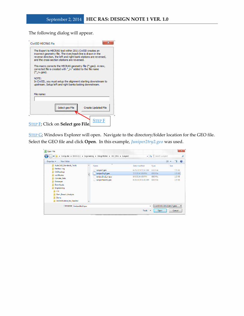
September 2, 2014 HEC RAS: DESIGN NOTE 1 VER. 1.0 The following dialog will appear.
STEP F; Click on Select geo File.
STEP G; Windows Explorer will open. Navigate to the directory/folder location for the GEO file. Select the GEO file and click Open. In this example, Juniper2try2.geo was used.
STEP F
HEC RAS: DESIGN NOTE 1 VER. 1.0 September 2, 2014
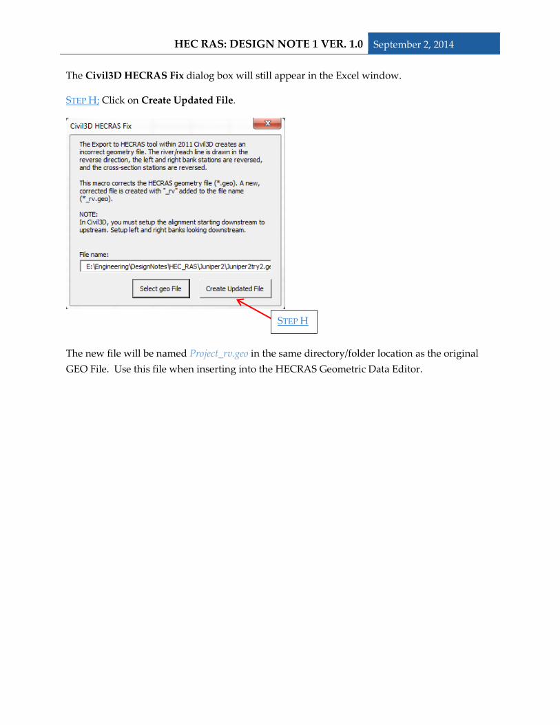
The Civil3D HECRAS Fix dialog box will still appear in the Excel window.
STEP H; Click on Create Updated File.
The new file will be named Project_rv.geo in the same directory/folder location as the original GEO File. Use this file when inserting into the HECRAS Geometric Data Editor.
STEP H
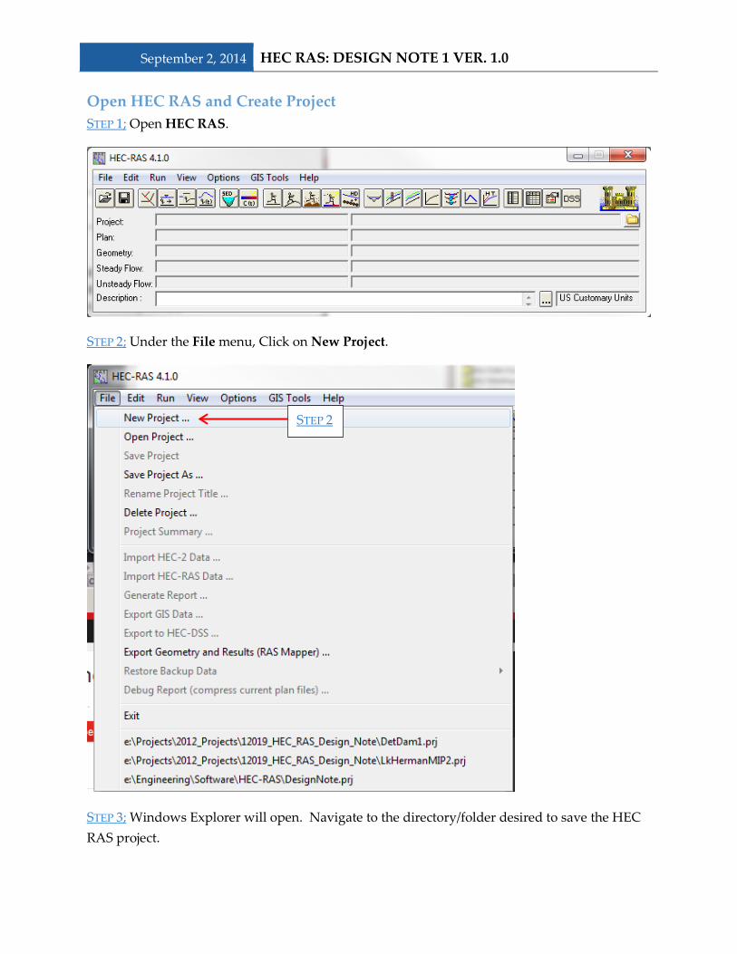
September 2, 2014 HEC RAS: DESIGN NOTE 1 VER. 1.0 Open HEC RAS and Create Project STEP 1; Open HEC RAS.
STEP 2; Under the File menu, Click on New Project.
STEP 3; Windows Explorer will open. Navigate to the directory/folder desired to save the HEC RAS project.
STEP 2
HEC RAS: DESIGN NOTE 1 VER. 1.0 September 2, 2014
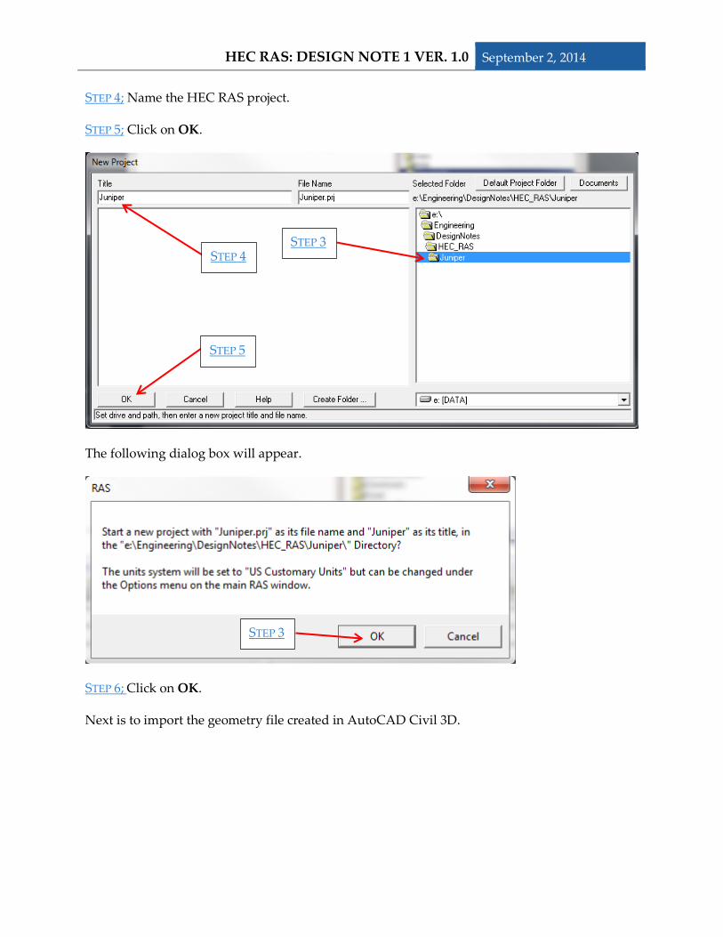
STEP 4; Name the HEC RAS project.
STEP 5; Click on OK.
The following dialog box will appear.
STEP 6; Click on OK.
Next is to import the geometry file created in AutoCAD Civil 3D.
STEP 3 STEP 4
STEP 5
STEP 3
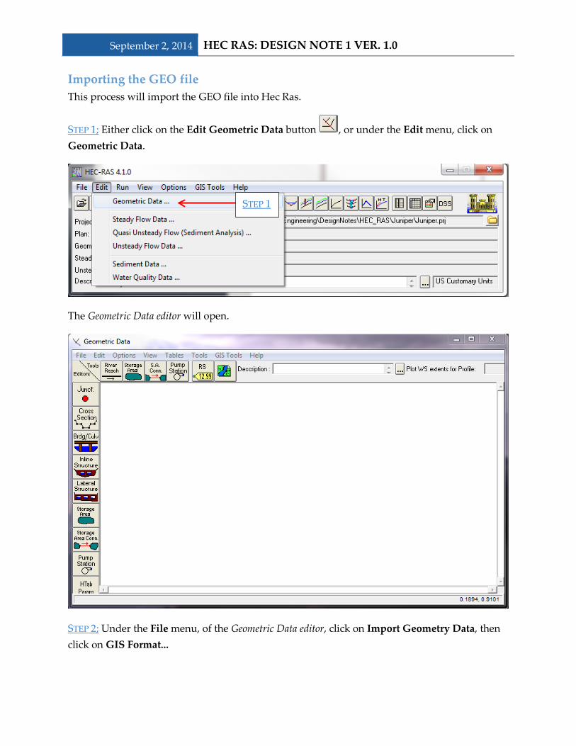
September 2, 2014 HEC RAS: DESIGN NOTE 1 VER. 1.0 Importing the GEO file This process will import the GEO file into Hec Ras.
STEP 1; Either click on the Edit Geometric Data button , or under the Edit menu, click on Geometric Data.
The Geometric Data editor will open.
STEP 2; Under the File menu, of the Geometric Data editor, click on Import Geometry Data, then click on GIS Format...
STEP 1

HEC RAS: DESIGN NOTE 1 VER. 1.0 September 2, 2014
A new Windows Explorer will open.
STEP 3; Navigate to the directory/folder where the Civil 3D file was exported to.
STEP 4; Click on the GEO file to import. In this example, JuniperSegment was used.
STEP 2
STEP 3 STEP 4
STEP 5
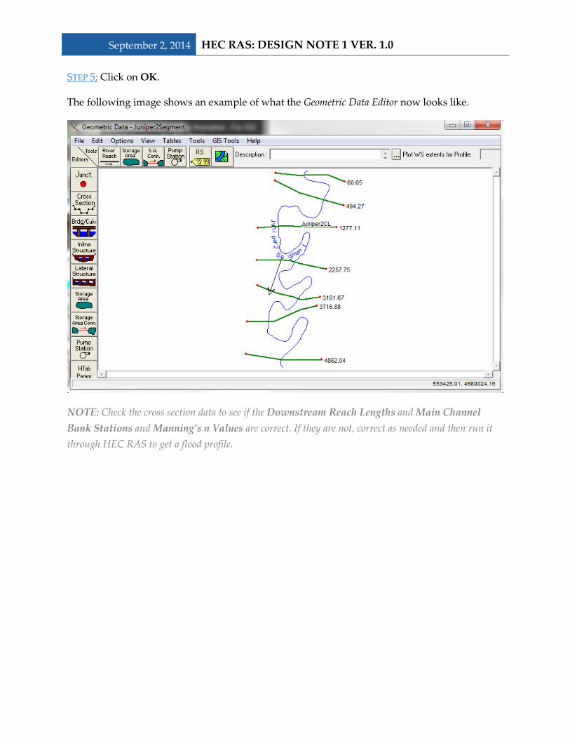
September 2, 2014 HEC RAS: DESIGN NOTE 1 VER. 1.0 STEP 5; Click on OK.
The following image shows an example of what the Geometric Data Editor now looks like.
NOTE: Check the cross section data to see if the Downstream Reach Lengths and Main Channel Bank Stations and Manning’s n Values are correct. If they are not, correct as needed and then run it through HEC RAS to get a flood profile.

HEC RAS: DESIGN NOTE 1 VER. 1.0 September 2, 2014
Flipping Coordinates, Method 2 NOTE: There are two ways to flip the coordinates, this is the second set of directions and does not use outside programs or downloads.
NOTE: The following directions go through how to flip the river reach and cross sections.
STEP A; In the Geometric Data Editor, under GIS Tools, click on Reach Invert Lines Table ...
The following table will appear.
STEP B; Click on the Flip Coord Order button . HEC RAS will ask “Do you want to flip the order of the points in the table?” Click on Yes.
The coordinates for the river reach have now been flipped and the river reach should be flowing the correct direction.
STEP A
STEP B