Lorraine Ozerovitch ( MSc, BSc, RGN ) Clinical Nurse Specialist

Exploring IMG Format
1
Exploring Garmin’s IMG Format
TRE , RGN, LBL, NET, NOD & DEM
(c) N Willink 21/08/2011
If you downloaded the manual from another source it will not be up to date.
more information on www.pinns.co.uk/osm/garmin.html
Latest Revision 02/03/2015

Exploring IMG Format
2
......................................................................................................................................................
TDB Editor 1.1 ............................................................................................................................... 4
Download & checkout the only tdb editor to: .............................................................................. 4
Introduction .................................................................................................................................... 4
Introduction .................................................................................................................................... 5
Garmin NT.................................................................................................................................. 5
IMG2TYP................................................................................................................................... 6
Garmin headers............................................................................................................................... 7
RGN header .................................................................................................................................... 7
How are all the elements (pois,polylines and polygons) stored?............................................... 8
Map levels............................................................................................................................... 8
Subdivisions............................................................................................................................ 9
Pointers in a subdivision........................................................................................................ 10
Finding number of pointers for each subdivision ....................................................................... 11
Start of Subdivisions in RGN + &29 ......................................................................................... 13
Locked TOPO maps...................................................................................................................... 17
LBL .............................................................................................................................................. 18
Lbl pointers NOT directly pointing to lbl1 label block........................................................... 20
Symbols ................................................................................................................................ 21
More than 1 label in NET ...................................................................................................... 21
POIs.............................................................................................................................................. 22
POIs with subtypes.................................................................................................................... 22
POIs with no Subtypes .............................................................................................................. 22
POI labels ................................................................................................................................. 22
POIs with extended types .......................................................................................................... 23
POLYLINES ................................................................................................................................ 24
Polyline Labels ......................................................................................................................... 24
Polylines withextended types 0 x 100+..................................................................................... 25
Length of a polyline type 100+ block ....................................................................................... 25
POLYGONS................................................................................................................................. 26
Polygon Labels ......................................................................................................................... 26
Polygons with extended types 0 x 100+.................................................................................... 26
Length of a polygon type 100+ block ....................................................................................... 26
Plotting Coordinates...................................................................................................................... 27
Plotting POIs............................................................................................................................. 27
Plotting Polylines .......................................................................................................................... 28
the first bitstream byte............................................................................................................... 28
The ‘official’ algorithm:............................................................................................................ 29
Starting to parse bitstreams........................................................................................................ 31
Plotting Routable polylines ....................................................................................................... 33
Left_shifting Coordinates.............................................................................................................. 34
Left_shifting Coordinates.............................................................................................................. 34
Bits_per_coord.......................................................................................................................... 34
Left Shifting.............................................................................................................................. 34
Plotting Polygons .......................................................................................................................... 36
Special cases in a bitstream ........................................................................................................... 36

Exploring IMG Format
3
TRE from 0x4a ............................................................................................................................. 38
TRE7 ............................................................................................................................................ 40
TRE8 ............................................................................................................................................ 41
TRE9 ............................................................................................................................................ 41
NET subfile .................................................................................................................................. 42
NET1 .................................................................................................................................... 42
Length of highways ............................................................................................................... 43
NOD subfile.................................................................................................................................. 44
NOD 1 .................................................................................................................................. 44
Pointer................................................................................................................................... 45
Flags at offset 1 ..................................................................................................................... 45
Direction Coordinates............................................................................................................ 45
Nodes Bytes .......................................................................................................................... 45
Flags A & B .......................................................................................................................... 45
Tables Header ....................................................................................................................... 46
Table A ................................................................................................................................. 46
NOD 2 ...................................................................................................................................... 47
DEM subfile ................................................................................................................................. 49
Creating IMG files ........................................................................................................................ 50
NT POIs........................................................................................................................................ 50
Extra POI data stream ................................................................................................................... 51

Exploring IMG Format
4
TDB Editor 1.1
Download & checkout the only tdb editor to:
• lock & unlock your Mapsource/Basecamp maps.
• restore Mapsource when it crashes
• rename any mapsource/basecamp name
• change mapnames so they are easier to read on your gps
• Lock & Unlock your own maps
• add/remove routable option
• force direct routing when it doesn't work
• add/remove profile option.
• add or edit copyright description when creating your own maps
• create or remove 'Reduced map window for printing' and other (printing or viewing)
messages
• disable any form of printing.
• add or resize Restricted Window View
• quickly identify & edit mapnames, useful when you want to isolate a particular IMG file.
Exploring IMG Format
5
Introduction
For anyone who wants to delve more deeply into the IMG structure John Mechalas (JM)‘ ‘Garmins
IMG File Format’ is a must read. We all owe a great deal to the author of cgpsmapper without
whom the booklet could not have existed.
Apart from this excellent document there seems to be nothing else available. Unfortunately, there
are some crucial errors in the JM’s description, making it more even more challenging.
Our aim is to tie up some loose ends and use frequent examples to make the format more accessible.
However, the IMG structure may to some still be a steep learning curve.
In this ongoing document I intend to focus on how to access and plot poi, polyline and polygon
data within an IMG file. From the picture in the title you can see that, my humble efforts after 3
years of frustration, have finally been successful. There were many occasions when I felt like giving
up as I was getting nowhere really fast.
IMG Explorer shows pointers and coordinates held in an IMG file and can be downloaded on
request only.
We would welcome any additional information or queries using email address found at :
www.pinns.co.uk/osm/
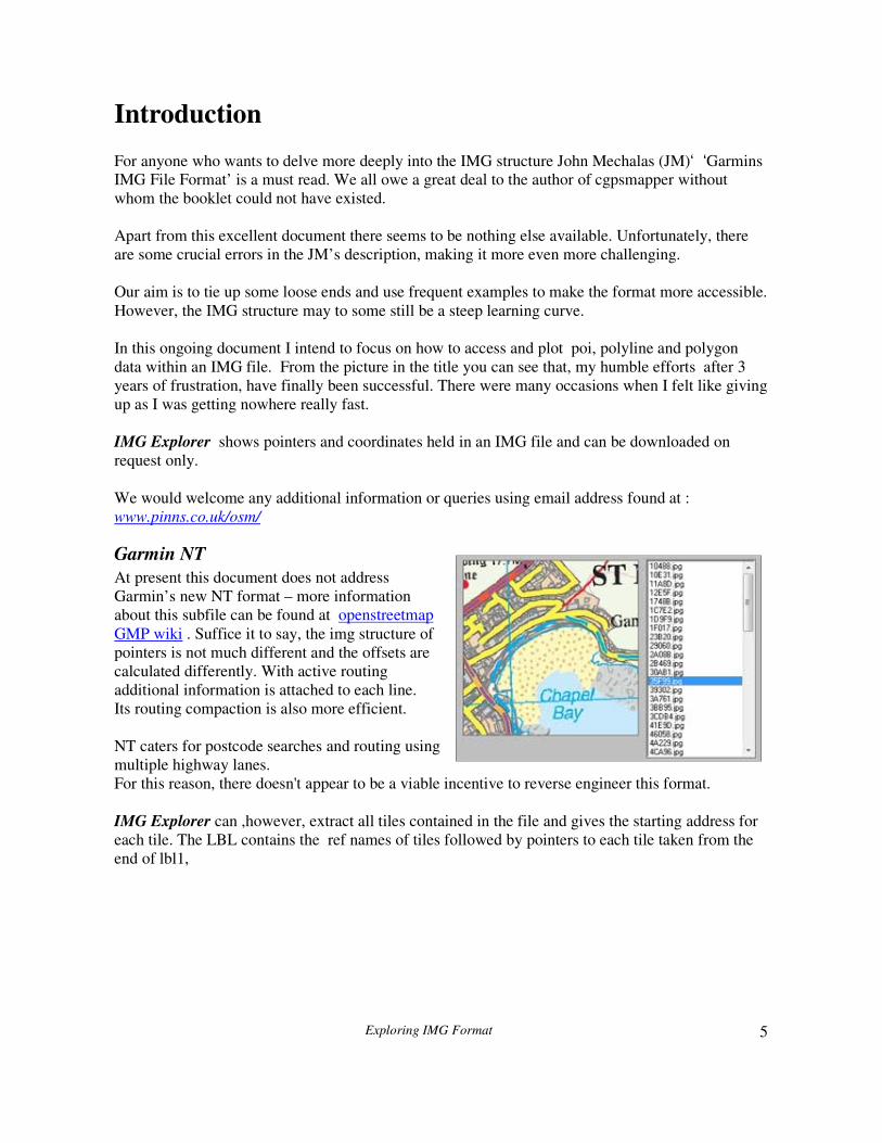
Garmin NT
At present this document does not address
Garmin’s new NT format – more information
about this subfile can be found at openstreetmap
GMP wiki . Suffice it to say, the img structure of
pointers is not much different and the offsets are
calculated differently. With active routing
additional information is attached to each line.
Its routing compaction is also more efficient.
NT caters for postcode searches and routing using
multiple highway lanes.
For this reason, there doesn't appear to be a viable incentive to reverse engineer this format.
IMG Explorer can ,however, extract all tiles contained in the file and gives the starting address for
each tile. The LBL contains the ref names of tiles followed by pointers to each tile taken from the
end of lbl1,

Exploring IMG Format
6
IMG2TYP
I’ve written this GUI to read IMG files and list all element types found in TRE so that they can be
saved as a TYP file. Check out on youtube
before after
TYPWiz
Use TYPWiz in connection with img2typ and you are well on your way to changing the rather drab
TYP files which accompany CN 2012-2015 maps ! Check out on Youtube

Exploring IMG Format
7
Garmin headers
An IMG file consists of several blocks, or sub files, each doing a specific job:
TRE, RGN, LBL , NET , NOD
The one we’re particularly interested in is the RGN subfile as we want to establish how all
highways, polygons and points of interests are plotted.
RGN header
In the RGN subfile we find the essential data for plotting our elements: coordinates, ,length of
highways, number of sides in each polygon etc. The header looks like this:
RGN Offset RGN Header BYTES
00 Header Length
02 GARMIN RGN 4
15 Pointer to beginning of RGN1 data, ie first subdivision to include
possible POIs,Indexed POIs,Polylines or Polygons or first map level
4
19 Length of this block 4
1D Pointer to RGN2 data block,contains extended polygons with types 0 x
100+ ; for undocumented details about its structure see further
4
21 Length of this block 4
39 Pointer to RGN3 data block ; this block contains extended polylines
with types 0 x 100+ ; for undocumented details about its structure see
further
4
3D Length of this block 4
55 Pointer to RGN4 block containing extended POIs ; for undocumented
details about its structure see further
4
59 Length of this block 4
65 FF
66 3F (7F) (o3)
67 0
68 20 3f f7 ff 3f 4
6D 4
75 Block or length 4
79 0x E3 (E5)3f

Exploring IMG Format
8
How are all the elements (pois,polylines and polygons) stored?
You could imagine that, as maps rely on individual nodes, pois are plotted first, followed by the
polygons etc. Yes and no. To understand how they are stored we need to look at :
1) maplevels
2) subdivisions.
Map levels
To save space, Garmin opted for a unique solution using maplevels and subdivisions.
To enable any kind of zooming, Garmin has decided to plot data in ‘zoom chunks’; the deeper the
zoom the more information it contains, ie the more highways etc are plotted.
At the lowest zoom, very few pois, if any and only a few highways are plotted - each created using
only a limited number of nodes,thus making them look straighter and more ragged .
These zoom levels are called maplevels ,each with subdivisions.
Maplevel 1 Subdivision
Subdivision
Maplevel 2 Subdivision
Subdivision
Subdivision
Maplevel 3 Subdivision
Regard map levels as groups of subdivisions .
Each map level is given a separate data block telling you:
1) what elements to plot
2) at what resolution /degrees of accuracy
3) how many subdivisions it has grouped together – sometimes none!

Exploring IMG Format
9
Subdivisions
Before we retrieve these maplevel blocks, let’s explore the nitty gritty of sublevels.
Each subdivision contains data visible at that level. Some subdivisions can share data with others.
The main highways are often plotted at different zoom levels and hence at a different resolution/
accuracy, whereas hardly any pois are plotted at the lowest level when you zoom out.
So there is a certain amount of doubling up, despite Garmin’s main aim to reduce its IMG file size.
How are these subdivisions constructed?
Consider the following:
1) POIs don’t need as much data as highways; in fact they only need one node
2) Not all highways are the same length
3) Polygons are not the same shape and their number of nodes can vary too.
Unfortunately, because the pois and highways data are not the same lengths, we need to know
where the starting points are for each element data block .
Ideal situation : every object the same length:
Poi 1
Poi 2
Polyline 1
Polyline 2
Polygon 1
Polygon 2
Garmin’s approach:
Poi 1 Poi 2 Polyline1
Polyline2
Polygon1
Polygon2

Exploring IMG Format
10
You could not have the ‘ideal’ situation unless you limit the number of nodes for each highway or
polygon to say 1000. That would be such a waste if the lines are short etc.
Note :The maximum length of a subdivision is finite – the exact length is not clear - , hence the
existence of numerous subdivisions depending on the amount of data within a maplevel.
Pointers in a subdivision
As a compromise, Garmin decided to plot all pois in a subdivision in one chunk, followed by
highways, followed by polygons.
To make sure we know where each element chuck starts we need to be given some pointers. These
pointers are not saved somewhere else but are given just before the start of a chunk. More
specifically, all pointers are given before the first chunk appears, at the beginning of each
subdivision and are 2 bytes long :
Pointer to chunk2 Pointer to chunk 3 Chunk 1 Chunk 2 Chunk 3
You would expect:
Pointer to
chunk1
Pointer to
chunk 2
Pointer to
chunk 3
Chunk 1 Chunk2 Chunk3
To save space we don’t need a pointer to the first element as it follows after the pointers,if any.
We can skip the pointer to chunk1 ;as each pointer is 2 bytes long , we know where chunk 1 starts
(6 bytes from the offset).
Example:
Pointer to chunk2 Pointer to chunk 3 Chunk 1 POIs Chunk 2
Polylines
Chunk 3
Polygons
So now we know the start of each element chunk.
There are 2 problems with this solution:
1) we need to know how many pointers there are in each subdivision
2) we need to know the length of each subdivision
If we didn’t know how many pointers there were, we wouldn’t know where our first element chunk started – for an answer see later .
Again , supposing we knew the number of pointers, we could find the first element block, but we
wouldn’t know where the next subdivision started, ie with its pointers
We can’t tell , unless the number of pointers & the start of each subdivision is stored elsewhere in
the IMG. They are not found in the RGN but in another subfile, called the TRE - see below
Exploring IMG Format
11
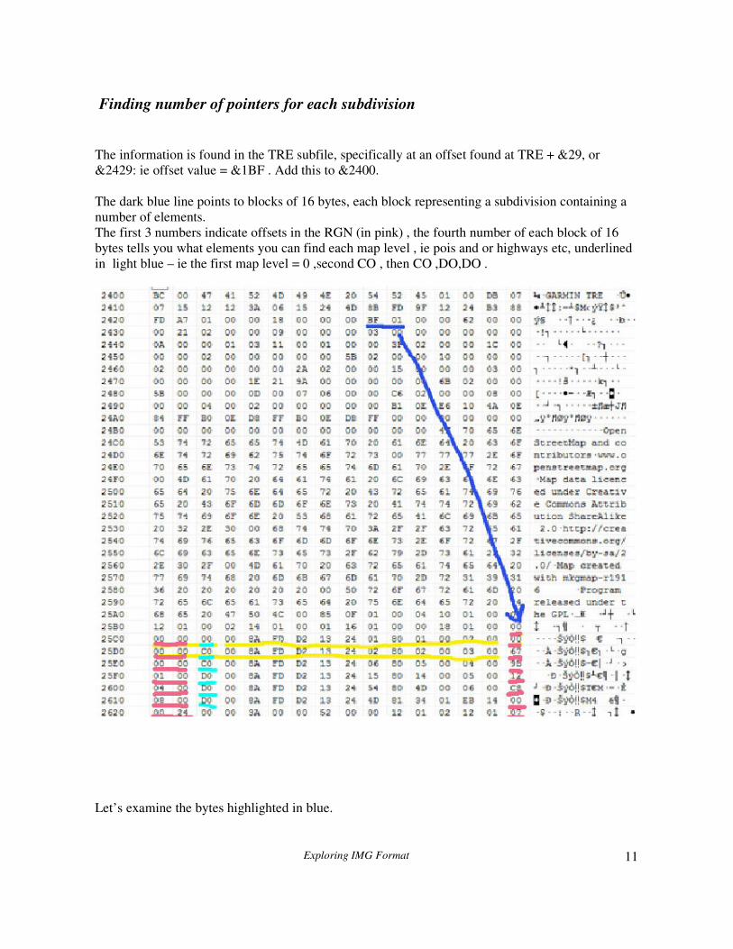
Finding number of pointers for each subdivision
The information is found in the TRE subfile, specifically at an offset found at TRE + &29, or
&2429: ie offset value = &1BF . Add this to &2400.
The dark blue line points to blocks of 16 bytes, each block representing a subdivision containing a
number of elements.
The first 3 numbers indicate offsets in the RGN (in pink) , the fourth number of each block of 16
bytes tells you what elements you can find each map level , ie pois and or highways etc, underlined
in light blue – ie the first map level = 0 ,second CO , then CO ,DO,DO .
Let’s examine the bytes highlighted in blue.

Exploring IMG Format
12
The table below shows you what these numbers mean:
Notice that the last subdivision contains all the elements (&FO) and so we need (4-1) 3 pointers.
Have a look at the picture below; you can see the RGN subfile starts at C00 .
Offset &15 (&C15) (4 bytes) always points to the start of the first subdivision chunk , ie it starts at
7D ( C00+7D) .
This number is underlined in blue.
Now look at C7D : underlined in green are 2 pointers , 28 00 and 35 01 – each pointer is always 2
bytes long .
Next, underlined in yellow we find some pois, ie the first one is 64 00 00 80 5E FF BD FF 17 –
more later.
Question: How do I know there are only two (green) pointers? Why is 64 00 not a pointer?
We know , because in TRE where the pointers are kept, we found this subdivision to contain &D0
types of elements , giving us 3 elements and hence 2 pointers.
code pois Indexes
pois
polylines polygons Pointers in
RGN
subdivision
10 √ 0
20 √ 0
40 √ 0
80 √ 0
C0 √ √ 1
D0 √ √ √ 2
E0 √ √ √ 2
F0 √ √ √ √ 3

Exploring IMG Format
13
Start of Subdivisions in RGN + &29
The first 3 bytes show pointers to a subdivision in the RGN file. Remember to add the offset found
at RGN + &15 to each of these values.
subdivision Offset Type of
Data
Number of
Pointers in
zoom chunk
Zoom level Real map
Levels
0 00 00 00 or 0 0 0 A1 5
1 00 00 00 or 0 C0 (2-1) =1 B1 4
2 67 00 00 or &67 C0 (2-1)=1 C1 3
3 9b 01 00 or &19b D0 (3 – 1)=2 D1 2
4 12 04 00 or &412 D0 (3 – 1)=2 E1 1
5 C8 08 00 or &8C8 D0 (3 – 1)=2 E2
6 etc etc etc F1 0
7 etc F2
In our example, we should find a new subdivision at offset 67, ie RGN+ &7D + &67
The next new subdivision is at RGN+ &7d + &19B etc
We have named the levels A – F for the sake of clarity .
We can see that zoom level ‘E’ has 2 pointers, and zoom level F has 5 pointers , remember the
above found sequence: 1,1,1,1,2,5
Important: The subdivisions in all mapevels apart from the last one have 16 bytes; all subdivisions
in the last level, in our case ‘F’, have only 14 bytes.
To obtain the address for each subdivision we add the offset to (RGN + pointer found in
(RGN+&15)) .
Example: in our case subdivision 5 has an offset of &8C8 . Supposing RGN starts at &E00 and the
offset pointer found at E00+&15 points to &7D
This subdivision, therefore, is found at :&8C8 + &E00 + &7D
Note: the size of a subdivision appears to be a critical; perhaps that is why IMGs created using
cgpsmapper seem to include a subdivision for almost every highway!

Exploring IMG Format
14
Grouping subdivisions into map levels
We mentioned earlier that maplevels are groups of subdivisions. If only we could find which
subgroups belonged to which maplevel . Fortunately we can, but NOT in the RGN subfile.
The information is found in TRE offset 0 x 21 .
It contains information about maplevels, not where they are,
but how many there are and also how many subdivisions
each map level has and also its resolution( bits_per_coord).
It doesn’t actually give you pointers to an address in the RGN
but the 3rd column (green) indicates the number of subdivisions
in each maplevel.
So we can see that map level 6 starts at subdivision 7
maplevel subdivision
1 1
2 2
3 3
4 4
5 5
6
6 7
8
9
5,F,1,0,
4,10,1,0,
3,12,1,0,
2,14,1,0,
1,16,2,0,
0,18,3,0,
Exploring IMG Format
15
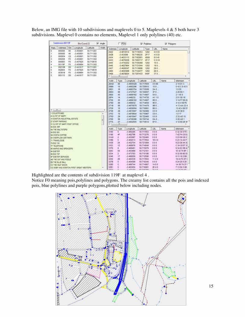
Below, an IMG file with 10 subdivisions and maplevels 0 to 5. Maplevels 4 & 5 both have 3
subdivisions. Maplevel 0 contains no elements, Maplevel 1 only polylines (40) etc.
Highlighted are the contents of subdivision 119F at maplevel 4 .
Notice F0 meaning pois,polylines and polygons. The creamy list contains all the pois and indexed
pois, blue polylines and purple polygons,plotted below including nodes.

Exploring IMG Format
16
‘the RGN block and beyond’
So, now we know how many map levels there are, but we still don’t know how long the last map
level block in the RGN is.
Fortunately, Garmin gives us the size of the RGN block, ie from the first subdivision containing
pointers and po1/highway/polygon data, to the end of the last one.
This is found at RGN + &2D
Now, interestingly there is some special data BEYOND this block not documented by Mechalas.
So, in addition to the subdivisions mentioned above, the RGN contains other chunks of data found
at pointers beyond &15.
Offset in RGN bytes
1d pointer 4
21 Length of block 4
39 Pointer to block 4
3d Length of block 4
55 Pointer to block 4
Some imgs store highways with types &100+ in the ‘green’ block . These types are used to perform
overlays ; this in theory ensures that certain highways,ie bridges, when given types &100+, acquire
the highest draw order and can overlap say Motorways. This, for some reason does not always
happen. More later. – see Polylines
Orange block is reserved for polygons with types &100+ - see Polygons.

Exploring IMG Format
17
Locked TOPO maps
You may find that these locked maps do not display the word ‘Garmin’ in a hex editor. If so, data
needs to be unscrambled. Find the first hex number and use the XOR function , ‘xorring’ every byte
by the first byte found. This will , ofcourse, still keep the file locked, but at least it’s readable.
Locked TOPO maps have the subdivisions pointers in the TRE encrypted.
(For those in the know, bytes &24 - &27 are used to unscramble the zoom level chunk and replaced
with new values)
This means you need to guess where each zoom level chunk starts and ends in the RGN. This RGN
data is itself not encrypted, so you can still read the first RGN map level chunk, including its
pointers, however you have no idea where it ends.
The problem is that pointers could be read as POIs etc and pois can be mistaken for polylines.
However, you could in theory when parsing , build in, best fit scenarios to check if the next piece of
data is a pointer, a POI or a polyline given the fact that coordinates couldn’t suddenly escape the
given boundaries.
If an IMG file contains pois,polylines or polygons with extended types, ie 0x100+ ( see below) ,
then these can be read and plotted without any problems. Even pointers to different subdivisions
remain unscrambled – see TRE7.

Exploring IMG Format
18
LBL
Where are all the names of streets,pois etc kept?
They are stored in the LBL subfile. However when you examine it, you more than likely won’t
recognize any labels ,as they are all encrypted.
Lets examine a POI data stream found in a RGN zoom level
46 DF 00 00 49 FF BB FF 02
The first and last ‘green’ byte denote type and subtype , so this POI’s type is 4602
The next three yellow bytes DF 00 00 are and offset in LBL , ore more precisely in LBL1 which is
an offset from the start of the LBL subfile.
However, bits 7 & 8 in the ‘third byte’ are reserved for something else:
Sometimes the third byte is 80, which implies that it is also found in the NET subfile if it’s a
highway. More importantly, if the third byte is a 80,40 C0 ,82,C2 etc then the pointer DOES NOT
point to an offset from the beginning of the lbl1 labels/names block. Instead, it points to a different
block where other information is found, including a pointer to the label lbl1 block – more later
For our purpose, we could just look at the first two bytes (you also need to check if bits 1 to 6 are
set in the third byte - only used if labels are found a long way from the beginning of this block).
It tells me that the name of the poi is found at offset 00DF (ie &DF) . The other 4 bytes following
the ‘yellow block’ provide the x and y coordinates.
However, it is not an offset starting from the beginning of the LBL subfile.
Instead, it is an offset from where the label block within the LBL starts ; the start of this label
block is defined in LBL + &15 or LBL1.
Each name in the label block ends with 00 if it’s not encoded.
Let’s have a look at an example:

Exploring IMG Format
19
We know all label data starts at offset &15 from the beginning of the LBL subfile.
Strangely, it points to 00 ( LBL + &D1). Add 1 and you get the sequence OC F5 4E 51
When you cross-check in the right column, below Default sort, it just shows gobbledy gook.
Let me tell you that all the values underlined in green read :’COUNTRY’
It looks as if the word is zipped in some way and most likely 6 bit encoding has been used.
First you need to change each of the 4 bytes into a binary format of zeros and ones . We don’t
know if it’s just 4 bytes, it could be more – see later.
In basic this would be:
For n = 7 to 0 step -1
If (byte and 2^n) = 2 ^n then string=string+”1” else
string=string+”0”
Next
Do this for each byte until you get a string which begins like this :
000011001111010101001110……….
Now split them into chunks of 6, as this is how most of the IMGs are encoded.
000011 001111 010101 001110 …….
Chunk 1 : 0 0 0 0 1 1
Read from right to left and you get:
1 1 0 0 0 or 2^0 + 2 ^ 1 + 0+ 0+ 0 = 3 which is the third letter ie ‘C’
Chunk 2 : 0 0 1 1 1 1
Read from right to left and you get:
1 1 1 0 0 0 or 2^0 + 2^1 +2^ 2 +2^3+ 0+ 0 = 15 which is the 15th letter, ie ‘O’
(The reason why we had to add 1 was because in our example the offset (+ 1) was given in the
Country records offset at lb + 1F- see further)
How do we know we’ve come to the end of a word? Garmin have though of this: if the 6 bit number
is > &2f then you’ve reached the end of your label. The next label starts in the next byte, so any
superfluous bits are just discarded and not used as the beginning of the next word.
Exploring IMG Format
20
Lbl pointers NOT directly pointing to lbl1 label block
Pointers are always 3 bytes, but sometimes the third byte ends in 80,82,C0,C6 etc
If bit 7 of the third byte is set then your lbl label refers to an offset in NET1 where you can find a 3
byte pointer to LBL1. Remember : Pointer = 1st byte + 2
nd byte + (3
rd byte ) mod 32
Net1 starts at offset 0x15 from the beginning of the NET subfile.
Example: 60 00 C1
60 00 01 (&C1 mod 32) points to offset &010060 from the NET1 block. Here we will find a
pointer to the main label block. Bit 7 of this byte may also be set! So, pointer NET1 Byte1+ NET1
byte + (NET1 byte 3) mod 32 should point to somewhere in LBL1, even if it is a blank label.
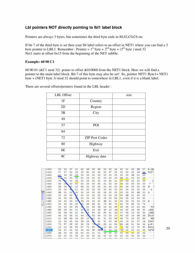
There are several offsets/pointers found in the LBL header :
LBL Offset size
1F Country
2D Region
3B City
49
57 POI
64
72 ZIP Post Codes
80 Highway
8E Exit
9C Highway data
Exploring IMG Format
21
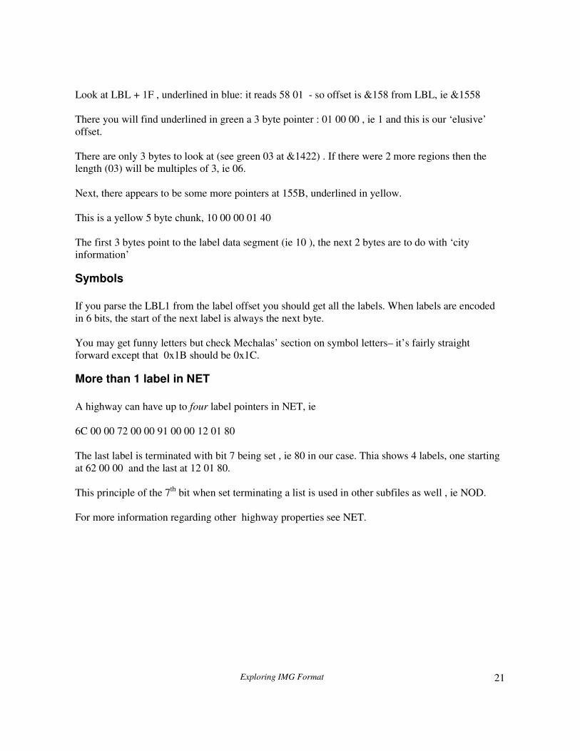
Look at LBL + 1F , underlined in blue: it reads 58 01 - so offset is &158 from LBL, ie &1558
There you will find underlined in green a 3 byte pointer : 01 00 00 , ie 1 and this is our ‘elusive’
offset.
There are only 3 bytes to look at (see green 03 at &1422) . If there were 2 more regions then the
length (03) will be multiples of 3, ie 06.
Next, there appears to be some more pointers at 155B, underlined in yellow.
This is a yellow 5 byte chunk, 10 00 00 01 40
The first 3 bytes point to the label data segment (ie 10 ), the next 2 bytes are to do with ‘city
information’
Symbols
If you parse the LBL1 from the label offset you should get all the labels. When labels are encoded
in 6 bits, the start of the next label is always the next byte.
You may get funny letters but check Mechalas’ section on symbol letters– it’s fairly straight
forward except that 0x1B should be 0x1C.
More than 1 label in NET
A highway can have up to four label pointers in NET, ie
6C 00 00 72 00 00 91 00 00 12 01 80
The last label is terminated with bit 7 being set , ie 80 in our case. Thia shows 4 labels, one starting
at 62 00 00 and the last at 12 01 80.
This principle of the 7th
bit when set terminating a list is used in other subfiles as well , ie NOD.
For more information regarding other highway properties see NET.
Exploring IMG Format
22
POIs
Points of interest all have a type number and a subtype number, ie type = 30 and subtype=01 . The
subtypes are supposed to be subsets of the main type: ie main type = amenity restaurant and subtype
= French cuisine
The length of each block varies depending on whether the subtype = 0 or not.
POIs with subtypes
type Lbl I Lbl II Lbl III longitude latitude subtype
POIs with no Subtypes
type lbl lbl lbl longitude latitude
How do we know if the poi has a subtype or not?
Answer: if (lblIII and 128)=128 then it contains a subtype.
This is where Mechalas is incorrect: it is not the bit 8 of first byte, but bit 8 of the 4th
byte.
POI labels
If bit 7 in the above LBLIII block is set then the labels for all pois are kept in a block named LBL6
ie found at LBL + 4 byte pointer at (LBL + &57)
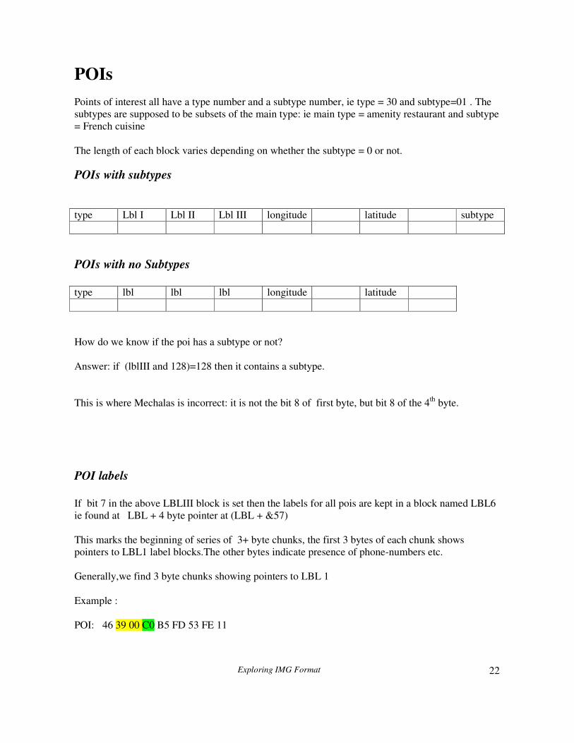
This marks the beginning of series of 3+ byte chunks, the first 3 bytes of each chunk shows
pointers to LBL1 label blocks.The other bytes indicate presence of phone-numbers etc.
Generally,we find 3 byte chunks showing pointers to LBL 1
Example :
POI: 46 39 00 C0 B5 FD 53 FE 11

Exploring IMG Format
23
Bit 8 of the lblIII pointer is set, ie &C0 : this means it has a subtype : Bit 7 is also set ; this means
00 39 is pointing to LBL 6 . ( &C0 = &40 + &80)
Now start from the beginning of LBL 6 ,underlined in blue and add &39 . It points to 3F 00 00
This,finally, is our lb1 pointer and hey presto we get the name of an amenity at offset 3F from
LBL1!
POIs with extended types
These are special POIs which may not show up on your GPS or Mapsource/Basecamp.
They could have types of 0x101, 0 x 10101 etc and are found at RGN4 + Offset &55 with length of
block at RGN4 +&68 containing additional information. The length of each block is variable
depending on bits 5 - 7 of the 2nd
byte .
In its simplest form its structure is:
Type +
&100
Sub type
mod 32
longitude
longitude
latitude latitude lbl lbl lbl
Example : 14 35 45 00 23 01 06 2E 00
This is a poi with type: &100 + &14 + &35 mod 32 = &11415
It has a label (yellow) at offset &2e06 from LBL1:.
We know it has a label as bit 5 was set , ie &20 + &15
Another example encountered has bit seven set:
Example
02 A1 90 FF 9F FF CD 00 00 E0 09 00 00 00 00 01
The bit stream following the yellow lbl label is at present unclear. It is possible that E0 marks
beginning of a possible bitmap stream/index with 09 being a flag and next 3/4 bytes a pointer to its
location. (The MDR has similar 2 byte codes , telling us how many bytes we should expect next, ie
number of characters and number of bytes to denote the index.)
For more information see TRE7

Exploring IMG Format
24
POLYLINES
Polylines ,like polygons, have a more complicated variable length.
The first 9 bytes are fixed :
0 1 2 3 4 5 6 7 8
type lblI lblII lblIII longitude longitude latitude latitude length
Because the highway node information can exceed 256 bytes we need to know when the length is >
256 and when it is not.
Answer: if the ( type byte and 128 = 128) then we know the length is determined by 2 bytes.
The first 8 bytes gives us the starting point coordinates of the highway – however, it’s as an offset
from the centre of a box defined by each subdivision in TRE .
Polyline Labels
If an IMG is not routable then the 3 LBL byte chunks behave normally and show pointers to lbl 1
If bit 8 in the above LBLIII block is set then these highways are routable. In which case the labels
of these highways are kept in a different block named NET1 ie found at NET + 4 byte pointer at
(NET + &15)
Railway lines , (type 0 x 14) are not routable (in theory) so lblIII should not have bit 8 set.
Exploring IMG Format
25
Polylines withextended types 0 x 100+
These are located in RGN3 offset &39 and are not routable; length of this block is found in RGN
offset &3d.
Their structure is quite different from polylines with types < 0 x &100.
0 1 2 3 4 5 6 7+ 3 bytes
Type +
&100
Sub type
mod 32
longitude longitude latitude latitude pointer length
+data
lbl
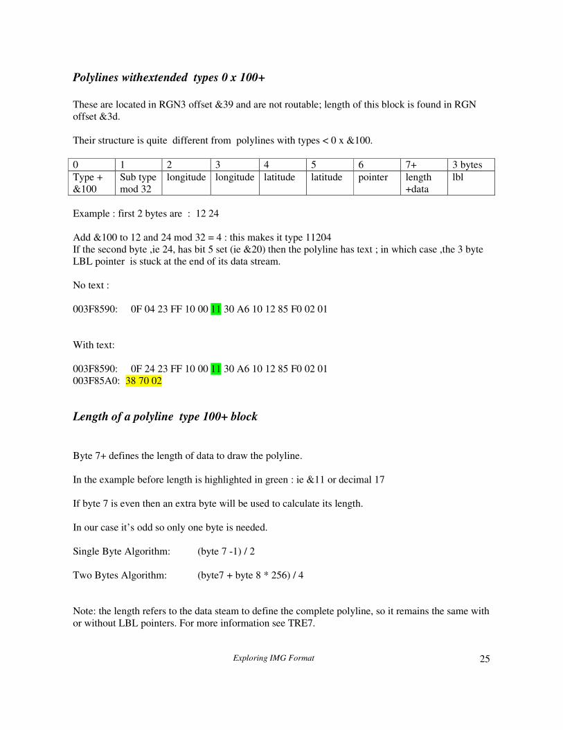
Example : first 2 bytes are : 12 24
Add &100 to 12 and 24 mod 32 = 4 : this makes it type 11204
If the second byte ,ie 24, has bit 5 set (ie &20) then the polyline has text ; in which case ,the 3 byte
LBL pointer is stuck at the end of its data stream.
No text :
003F8590: 0F 04 23 FF 10 00 11 30 A6 10 12 85 F0 02 01
With text:
003F8590: 0F 24 23 FF 10 00 11 30 A6 10 12 85 F0 02 01
003F85A0: 38 70 02
Length of a polyline type 100+ block
Byte 7+ defines the length of data to draw the polyline.
In the example before length is highlighted in green : ie &11 or decimal 17
If byte 7 is even then an extra byte will be used to calculate its length.
In our case it’s odd so only one byte is needed.
Single Byte Algorithm: (byte 7 -1) / 2
Two Bytes Algorithm: (byte7 + byte 8 * 256) / 4
Note: the length refers to the data steam to define the complete polyline, so it remains the same with
or without LBL pointers. For more information see TRE7.

Exploring IMG Format
26
POLYGONS
Data structure is the same as for polylines.
Polygon Labels
Again see polylines
Polygons with extended types 0 x 100+
These are located in RGN2 offset &1D ; length of this block is found in RGN offset &21.
Length of a polygon type 100+ block
See Polylines.

Exploring IMG Format
27
Plotting Coordinates
Finally we come to plotting our elements.
The coordinates are stored in 2 byte offsets from the centre of your current zoom level map
Earlier on we gave the following example
for map zoom levels found in TRE where
the last two digits determine the number of subdivisions
in each map level.
This tells us that we have 5 different map levels. Remember, at each level elements may be plotted.
The first level you encounter tends to be empty, not referring g to any elements and is used for
determining boundaries.
Look at the last level : 0 , 18 , 5 ,0
The second number (&18) is vital to the way elements are plotted. It is referred to as the bits per
coordinate (bpc)
The formula for getting latitude and longitude degrees : 1 garmin unit = 360/(2^24)
24 (or &h18) represents the bpc
At each zoom level you swap 24 for the second number in our table . Remember, this will be
different for each IMG.
In our case the various bpcs are : &F, &10,&12,&14,&16,&18 , increasing the accuracy of the
coordinates.
Plotting POIs
64 15 03 C0 1F 00 1C 00 0F
You need to add these two byte chucks in green to the 3 byte latitude + longitude centres defined in
TRE +&29 – see earlier. Add the first two to the latitude,and the second 2 to the longitude.
Next, multiply each by 360/(2^24) to obtain degrees
85,F,1,0,
4,10,1,0,
3,12,1,0,
2,14,1,0,
1,16,2,0,
0,18,5,0,
Exploring IMG Format
28
Check if the value of your two byte chunks is >&7FFF:
If it is, then the result is negative , ie -(65536 - value),
Plotting Polylines
Before attempting to plot polylines or polyhedrons, you must be familiar to some extent with
Mechalas description of bitstream parsing. This is heavy going but a few additional examples may
help:
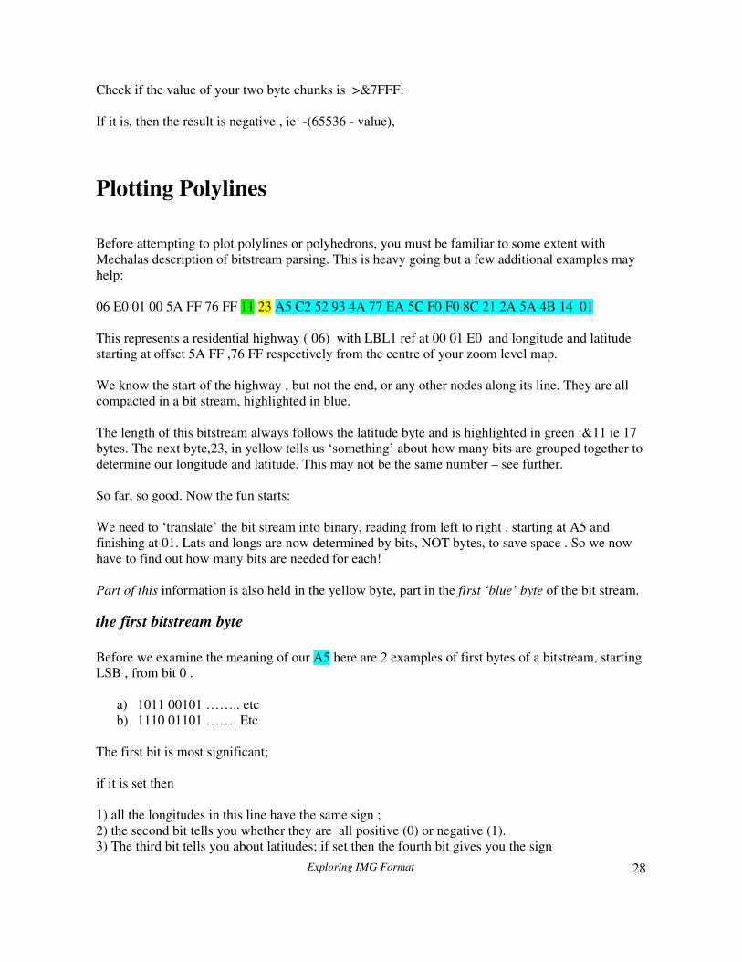
06 E0 01 00 5A FF 76 FF 11 23 A5 C2 52 93 4A 77 EA 5C F0 F0 8C 21 2A 5A 4B 14 01
This represents a residential highway ( 06) with LBL1 ref at 00 01 E0 and longitude and latitude
starting at offset 5A FF ,76 FF respectively from the centre of your zoom level map.
We know the start of the highway , but not the end, or any other nodes along its line. They are all
compacted in a bit stream, highlighted in blue.
The length of this bitstream always follows the latitude byte and is highlighted in green :&11 ie 17
bytes. The next byte,23, in yellow tells us ‘something’ about how many bits are grouped together to
determine our longitude and latitude. This may not be the same number – see further.
So far, so good. Now the fun starts:
We need to ‘translate’ the bit stream into binary, reading from left to right , starting at A5 and
finishing at 01. Lats and longs are now determined by bits, NOT bytes, to save space . So we now
have to find out how many bits are needed for each!
Part of this information is also held in the yellow byte, part in the first ‘blue’ byte of the bit stream.
the first bitstream byte
Before we examine the meaning of our A5 here are 2 examples of first bytes of a bitstream, starting
LSB , from bit 0 .
a) 1011 00101 …….. etc
b) 1110 01101 ……. Etc
The first bit is most significant;
if it is set then
1) all the longitudes in this line have the same sign ;
2) the second bit tells you whether they are all positive (0) or negative (1).
3) The third bit tells you about latitudes; if set then the fourth bit gives you the sign

Exploring IMG Format
29
you can see that both a and b start with the first and third byte being set ( =1)
Longitude Longitude Latitude Latitude Effect
1= Has
same sign
1= -
0 = +
1= Has
same sign
1= -
0 = +
1 0 1 1 Going east
and south
1 1 1 0 Going west
and north
Now examine the first byte in our example above , ie A5:
In binary this is 10100101 bit 7 to bit 0
Next, reverse the bits and we see that it starts with 1010 0101 bit 0 to bit 7
This implies that longitude is always positive and latitude is positive as well (1111 0101 would
have signified all values being negative)
How is this going to help us to determine the bit lengths of our latitude and longitude?
If it is always positive or negative the shape of the line tends to be a curve. If you want to check
your code look for power cables or motor ways, they should general start with a 4 bit sign
determinator.
The ‘official’ algorithm:
Mechalas gives the following formula:
Longitude = 2 + base value + longitude sign + extra bits set in LBL (but see further!!!)
Latitude = 2 + base value + latitude sign + extra bits set in LBL
I have found this to be incorrect; in my opinion it is:
Longitude = 2 + base value + longitude sign
Latitude = 2 + base value + latitude sign
If the extra LBL bits are set then add 1 bit - this bit seems indicated the beginning of a line if set
(ie 1).

Exploring IMG Format
30
When the Extra bit is set additional information about the highway is held in the NET and NOD
subfile regarding speed and road type. It also means that the highway is routable.
If the sign of latitude is always the same then the latitude sign value = 0 else it is 1. Same applies
to longitude.
In our example all longitude and latitude values remain the same ,ie always positive or always
negative.
Let’s return to the base byte ( yellow above , ie …FF 11 23 A5…) : ie 23 :
1st ‘digit’ refers to latitude, second to longitude ( MSB to LSB)
Longitude = 2 + 3 (base value) + 0 = 5
Latitude = 2 + 2 (base value) + 0 = 4
If the base value is higher than 9 , ie B4 , 6A, or AC etc) then see Mechalas.

Exploring IMG Format
31
Starting to parse bitstreams
Next, we start parsing the bit stream and begin with the fifth bit, because we’ve already used the
first 4 to determine the sign for our coordinates.
Remember, our starting point is not always the 5th
bit ;it could be 3rd
or 4th
; see following
examples.
In our previous examples the purple bits always were 4 bits . Now, some examples when this is not
the case.
Example 2
100 1001 …
The first two bits are as above,ie 10, but then latitude is set to 0 (3rd
bit) meaning its sign is variable
and could be positive or negative. There is now no need for a 4th
bit. We know that our longitude
is always positive, and our latitude is variable, both positive and negative – total number of bits = 3.
Longitude = 2 + (base value) + 0 + 0
Latitude = 2 + (base value) + 1 + 0 ( 1 indicates value being variable)
We start parsing after the 3rd
bit, ie 1001…
Example 3
010 1011 …
In this case the longitude bit starts with zero, meaning its sign is variable
Longitude = 2 + (base value) + 1
Latitude = 2 + (base value) +0
Again we start parsing after the 3rd
bit , ie 1011
Example 4
00 10010
Here both longitude and latitude are 0 meaning both signs are variable ; no more bits needed to
mark our signs.
Longitude = 2+ (base value) + 1
Latitude = 2 + (base value) +1
Parsing starts after the 2nd
bit.

Exploring IMG Format
32
If you are writing your own code it is recommended you look at the last subdivision containing
polylines as defined in TRE, as we don’t need to bother about left shifting the values – more later.
(There is a minor binary value error in Mechalas description,ie 0 x ab )
We now know the length for each longitude and latitude chunk and can start parsing; remember the
values are added to the coordinates of the centre of your maplevel block – see plotting POIs
Returning to our example
06 E0 01 00 5A FF 76 FF 11 23 A5 C2 52 93 4A 77 EA 5C F0 F0 8C 21 2A 5A 4B 14 01
1) start with 5th
bit of your total stream
2) longitude = 3 bits and latitude = 3 bits: so group the rest of your bitstream into sets of 3’s
x of point 1 : 5A FF in degrees: ( FF5A + centre longitude) * 360/(2^24)
y of point 1 : 76 FF in degrees: ( FF76+ centre latitude) * 360/(2^24)
x of point 2 : x=x + decimal( first 3 bits) in degrees : x * 360/(2^24)
y of point 2 :y=y + decimal( second 3 bits): in degrees : y * 360/(2^24)
x of point 2 : x=x + decimal( third 3 bits) : x * 360/(2^24)
y of point 2 :y=y + decimal( fourth 3 bits) : y * 360/(2^24)
Exploring IMG Format
33
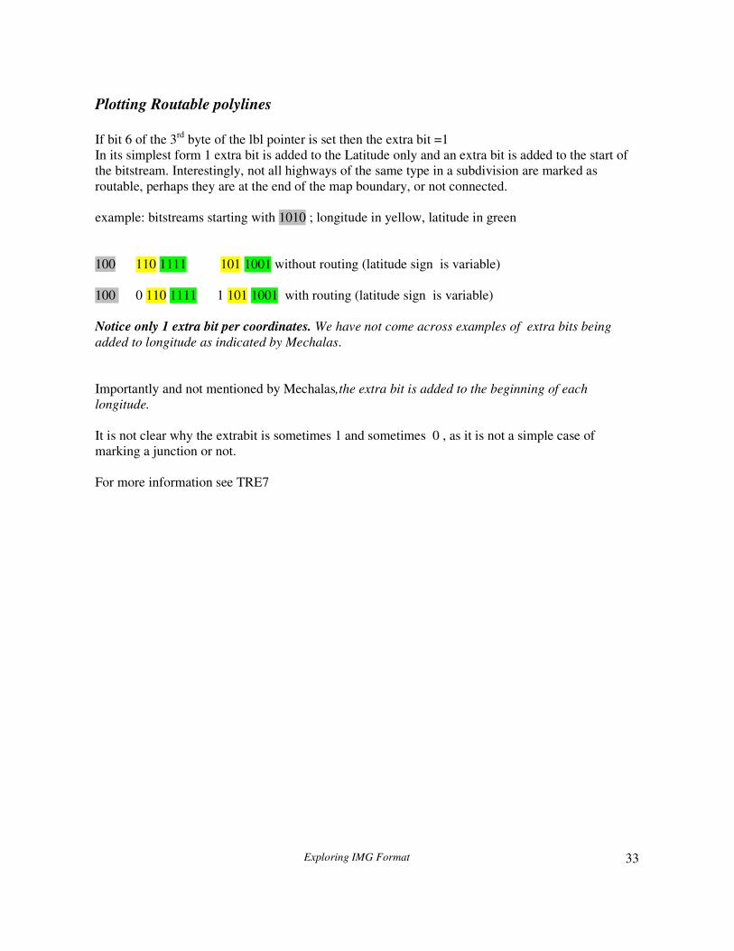
Plotting Routable polylines
If bit 6 of the 3rd
byte of the lbl pointer is set then the extra bit =1
In its simplest form 1 extra bit is added to the Latitude only and an extra bit is added to the start of
the bitstream. Interestingly, not all highways of the same type in a subdivision are marked as
routable, perhaps they are at the end of the map boundary, or not connected.
example: bitstreams starting with 1010 ; longitude in yellow, latitude in green
100 110 1111 101 1001 without routing (latitude sign is variable)
100 0 110 1111 1 101 1001 with routing (latitude sign is variable)
Notice only 1 extra bit per coordinates. We have not come across examples of extra bits being
added to longitude as indicated by Mechalas.
Importantly and not mentioned by Mechalas,the extra bit is added to the beginning of each
longitude.
It is not clear why the extrabit is sometimes 1 and sometimes 0 , as it is not a simple case of
marking a junction or not.
For more information see TRE7
Exploring IMG Format
34
Left_shifting Coordinates
The more you zoom out , the more sparse the map is going to be. You don’t need to plot all POIs
and your highways require fewer nodes, so the length of each bitstream tends to be short.
Also, crucially, you can reduce the accuracy of your coordinates and save bits.
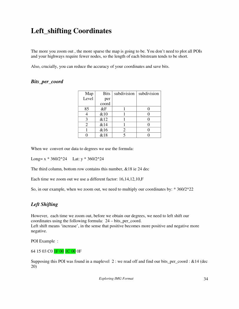
Bits_per_coord
When we convert our data to degrees we use the formula:
Long= x * 360/2^24 Lat: y * 360/2^24
The third column, bottom row contains this number, &18 ie 24 dec
Each time we zoom out we use a different factor: 16,14,12,10,F
So, in our example, when we zoom out, we need to multiply our coordinates by: * 360/2^22
Left Shifting
However, each time we zoom out, before we obtain our degrees, we need to left shift our
coordinates using the following formula: 24 – bits_per_coord.
Left shift means ‘increase’, in the sense that positive becomes more positive and negative more
negative.
POI Example :
64 15 03 C0 1F 00 1C 00 0F
Supposing this POI was found in a maplevel 2 : we read off and find our bits_per_coord : &14 (dec
20)
Map
Level
Bits
per
coord
subdivision subdivision
85 &F 1 0
4 &10 1 0
3 &12 1 0
2 &14 1 0
1 &16 2 0
0 &18 5 0

Exploring IMG Format
35
First change 1F00 into bits. 1111000 , starting from bit 0 to 7
We left_shift by (24-20) ie 4 to get 00001111000: 576 or &h240
Take care when numbers to be left_shifted are negative, ie &FFF7.
Note: you need to left_shift all two byte values before adding them to the current coordinates if resolution is < 24 . Three byte values are NOT left_shifted.

Exploring IMG Format
36
Plotting Polygons
Polygons are parsed in the same way as polylines.
You will notice that most polygons are not drawn at the highest zoom level/ sublevel and that lower
zoom levels generally contain a bounding box of &4B or 4A.
Interestingly and perhaps not surprisingly ,shapes are not closed.
Special cases in a bitstream
Mechalas has given us some valid pointers to how we need to parse a bitstream chunk with ONLY
its last bit set, ie 001 or 00001 etc (LSB to MSB).
However,unfortunately his description is somewhat incomplete.
Only cgpsmapper and topo maps seem to use this feature , so it is worth experimenting with
cgpsmapper to unravel its obvious complexity.
Use gpsmapedit to create various zigzag lines and save as a mp. Then export using cgpsmapper.
Regard 0001 etc as a flag to indicate special cases to create larger numbers,either negative or
positive.
The sign value is determined by what follows!
Examples: (from LSB to MSB)
a) 00001 001001 special case followed by negative number .
This has the effect of increasing its negative value - documented by Mechalas.
b) 00001 001010 special case followed by positive number
This has the effect of increasing its positive value – not documented.
Value = 2^4+ 20
c) There is an additional case,also undocumented , when ,say, 0001 is followed , often several
times, by another 0001 , until a lower bit is set. - this only works if the extrabit is not set (
information given by Attila)

Exploring IMG Format
37
For example:
0001 0001 0001 1100
This creates a value of 2^3 (0001) + 2^3 + 2^3 + 3 (1100)
A visual example:
The following bitstream of a polygon contains somewhere in the middle some consecutive
segments with last bit set only.
0000001 0000001 0000001 0000001
3F 44 94 D9 54 B3 C1 CF 10 20 FC 52 B4 9F EE 55 53 EC 62 34 C8 0F
FC 43 ED 02 81 43 AE 30 81 DC 0C 92 45 4F 80 1B 30 18 8B 43 8B 20
3B DC 00 24 5B CB 06 00 81 40 60 00 08 04 02 4B 00 00 10 58 04
(length=&3F ,base value=&44 etc)
And looks like this with polygon closed:
Exploring IMG Format
38
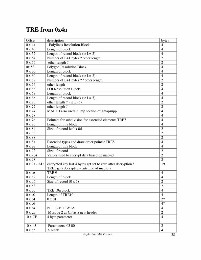
TRE from 0x4a
Offset description bytes
0 x 4a Polylines Resolution Block 4
0 x 4e Length of block 4
0 x 52 Length of record block (ie L= 2) 4
0 x 54 Number of L+1 bytes ? other length 2
0 x 56 other length ? 2
0x 58 Polygon Resolution Block 4
0 x 5c Length of block 4
0 x 60 Length of record block (ie L= 2) 4
0 x 62 Number of L+1 bytes ? / other length 2
0 x 64 other length 2
0 x 66 POI Resolution Block 4
0 x 6a Length of block 4
0 x 6e Length of record block (ie L= 3) 4
0 x 70 other length ? (ie L=5) 2
0 x 72 other length ? 2
0 x 74 MAP ID also used in mp section of gmapsupp 4
0 x 78 4
0 x 7c Pointers for subdivision for extended elements TRE7 4
0 x 80 Length of this block 4
0 x 84 Size of record ie 0 x 0d 2
0 x 86 2
0 x 88 2
0 x 8a Extended types and draw order pointer TRE8 4
0 x 8e Length of this block 4
0 x 92 Size of record 2
0 x 96+ Values used to encrypt data based on map-id 2
0 x 98 2
0 x 9a - AD encrypted key last 4 bytes get set to zero after decryption !
TRE1 gets decrypted - firts line of mapsets
19
0 x ae TRE 9 4
0 x b2 Length of block 4
0 x b6 Size of record (0 x 5) 2
0 x b8 2
0 x bc TRE 10n block 4
0 x c0 Length of TRE10 4
0 x c4 0 x 01 2?
0 x c6 4?
0 x ca NT TRE11? &1A 4
0 x cE Must be 2 as CF as a new header 2
0 x CF 4 byte parameter 4
0 x d3 Parameters 03 00 2
0 x d5 A block 4
Exploring IMG Format
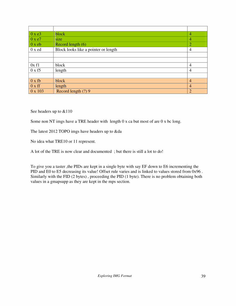
39
0 x e3 block 4
0 x e7 size 4
0 x eb Record length (6) 2
0 x ed Block looks like a pointer or length 4
0x f1 block 4
0 x f5 length 4
0 x fb block 4
0 x ff length 4
0 x 103 Record length (?) 9 2
See headers up to &110
Some non NT imgs have a TRE header with length 0 x ca but most of are 0 x bc long.
The latest 2012 TOPO imgs have headers up to &da
No idea what TRE10 or 11 represent.
A lot of the TRE is now clear and documented ; but there is still a lot to do!
To give you a taster ,the PIDs are kept in a single byte with say EF down to E6 incrementing the
PID and E0 to E5 decreasing its value! Offset rule varies and is linked to values stored from 0x96 .
Similarly with the FID (2 bytes) , proceeding the PID (1 byte). There is no problem obtaining both
values in a gmapsupp as they are kept in the mps section.
Exploring IMG Format
40
TRE7
Each block of extended elements, contains elements at various resolutions. So, if your IMG
contains extended pois or polylines etc then they too are plotted at different resolutions.
Trouble is, that without any pointers, it is impossible to plot these extended elements correctly as
they may need to be left_shifted
Fortunately,TRE7 provides essential pointers for each subdivision. Interestingly, in locked files
these are not scrambled!
Pointers for each subdivision are found at 0x7C offset from TRE, called TRE7, usually in blocks
of 13. Length of this block at 0x80
The size of each block is defined in TRE + &84 , ie &0D
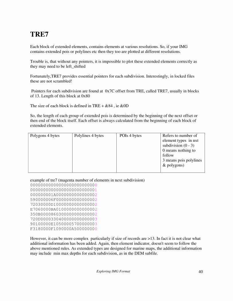
So, the length of each group of extended pois is determined by the beginning of the next offset or
then end of the block itself. Each offset is always calculated from the beginning of each block of
extended elements.
Polygons 4 bytes Polylines 4 bytes POIs 4 bytes Refers to number of
element types in nxt
subdivision (0 - 3)
0 means nothing to
follow
3 means pois polylines
& polygons)
example of tre7 (magenta number of elements in next subdivision) 00000000000000000000000000
00000000000000000000000001
000000001A0000000000000002
590000006F0000000000000002
72030000D10000000000000002
E7060000BA0100000000000002
350B0000860300000000000002
720D0000330400000000000003
90100000E10500005700000003
F3180000F1090000A500000000
However, it can be more complex particularly if size of records are >13. In fact it is not clear what
additional information has been added. Again, then element indicator, doesn't seem to follow the
above mentioned rules. As extended types are designed for marine maps, the additional information
may include min max depths for each subdivision, as in the DEM subfile.

Exploring IMG Format
41
example 2
00000000000000000F000000006032000024400000C2870100F4250200
00000000000000000F000000006032000024400000C2870100F4250200
00000000000000000F000000006032000024400000C2870100F4250200
000000000000000007000000006032000024400000C2870100F4250200
000000000502000007000000006032000024400000C2870100F4250200
000000007C04000006000000006032000024400000C2870100F4250200
00000000DD04000004000000006032000024400000C2870100F4250200
00000000E505000007000000006032000024400000C2870100F4250200
00000000D808000004000000006032000024400000C2870100F4250200
000000004F09000005000000006032000024400000C2870100F4250200
00000000C409000005000000006032000024400000C2870100F4250200
00000000060A000004000000006032000024400000C2870100F4250200
000000003B0A000004000000006032000024400000C2870100F4250200
00000000580A000004000000006032000024400000C2870100F4250200
00000000580A000005000000006032000024400000C2870100F4250200
00000000770A00000F000000006032000024400000C2870100F4250200
00000000EB0C00000D000000006032000024400000C2870100F4250200
00000000660D000000000000006032000024400000C2870100F4250200
00000000660D000004000000006032000024400000C2870100F4250200
9A030000BA0D00000669020000A2320000CE4E0000358A0100F6250200
24070000270E000007B6040000DE320000ED5400003D930100F6250200
780A00004E10000004F6060000383400002A6900007B980100FA250200
TRE8
This block located at TRE + &h8a contains all the extended types and their draworder found in a
particular IMG file. Each element data can be 3 bytes or 4 bytes long.
Example: &10F08
Typ mod &100 draworder subtype ?
F 2 8 0
An element with the lowest drawnumber seems to be at the highest level, ie the top,
The order in which they are plotted is:
Polylines ,followed by polygons,followed by POIs. Interesting that POIs can have a draworder!
an example of TRE8
1 1 2 0
1 1 3 0 1 1 4 0
6 1 1 0
6 5 3 0
6 5 4 0
TRE9
Nothings is known about this section; if present , there only seems to be one record of 5 bytes
Exploring IMG Format
42
NET subfile
Here we find additional data concerning routable highways ,such as its length , its direction (if one
way),the maximum speed allowed, and its house address information if any.
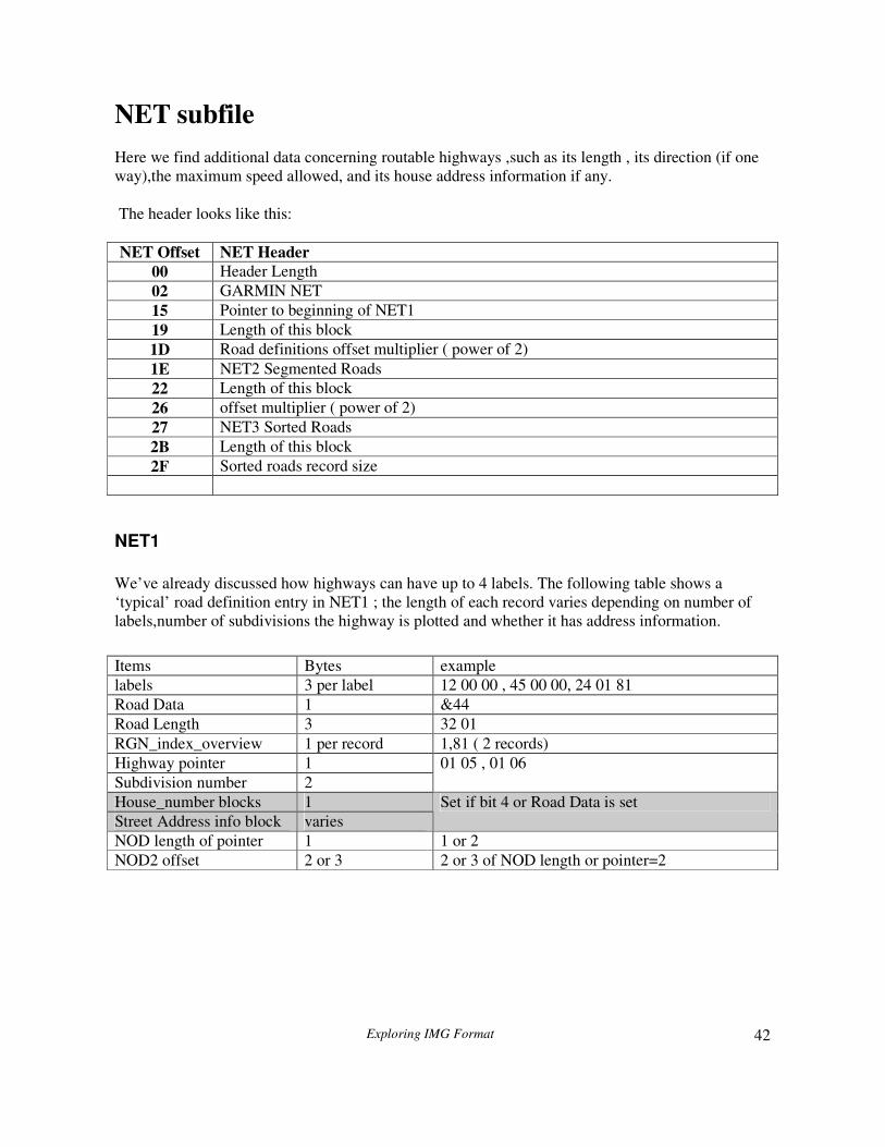
The header looks like this:
NET Offset NET Header
00 Header Length
02 GARMIN NET
15 Pointer to beginning of NET1
19 Length of this block
1D Road definitions offset multiplier ( power of 2)
1E NET2 Segmented Roads
22 Length of this block
26 offset multiplier ( power of 2)
27 NET3 Sorted Roads
2B Length of this block
2F Sorted roads record size
NET1
We’ve already discussed how highways can have up to 4 labels. The following table shows a
‘typical’ road definition entry in NET1 ; the length of each record varies depending on number of
labels,number of subdivisions the highway is plotted and whether it has address information.
Items Bytes example
labels 3 per label 12 00 00 , 45 00 00, 24 01 81
Road Data 1 &44
Road Length 3 32 01
RGN_index_overview 1 per record 1,81 ( 2 records)
Highway pointer 1
Subdivision number 2
01 05 , 01 06
House_number blocks 1
Street Address info block varies
Set if bit 4 or Road Data is set
NOD length of pointer 1 1 or 2
NOD2 offset 2 or 3 2 or 3 of NOD length or pointer=2
Exploring IMG Format
43
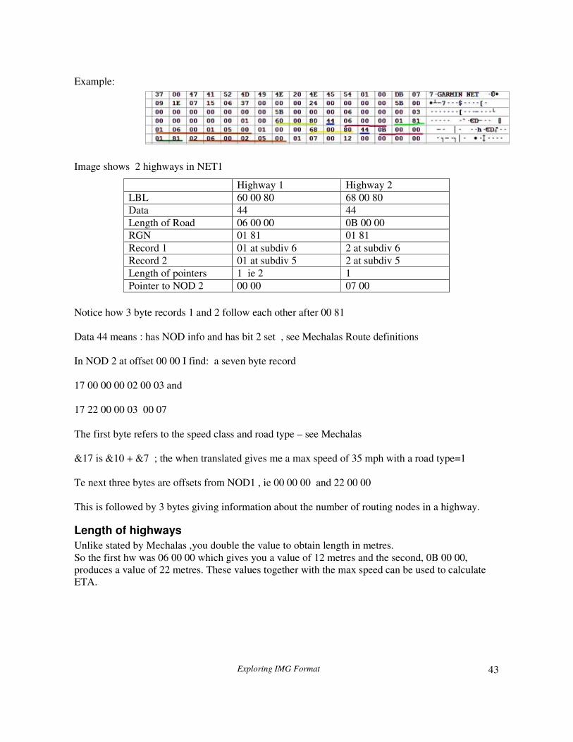
Example:
Image shows 2 highways in NET1
Notice how 3 byte records 1 and 2 follow each other after 00 81
Data 44 means : has NOD info and has bit 2 set , see Mechalas Route definitions
In NOD 2 at offset 00 00 I find: a seven byte record
17 00 00 00 02 00 03 and
17 22 00 00 03 00 07
The first byte refers to the speed class and road type – see Mechalas
&17 is &10 + &7 ; the when translated gives me a max speed of 35 mph with a road type=1
Te next three bytes are offsets from NOD1 , ie 00 00 00 and 22 00 00
This is followed by 3 bytes giving information about the number of routing nodes in a highway.
Length of highways
Unlike stated by Mechalas ,you double the value to obtain length in metres.
So the first hw was 06 00 00 which gives you a value of 12 metres and the second, 0B 00 00,
produces a value of 22 metres. These values together with the max speed can be used to calculate
ETA.
Highway 1 Highway 2
LBL 60 00 80 68 00 80
Data 44 44
Length of Road 06 00 00 0B 00 00
RGN 01 81 01 81
Record 1 01 at subdiv 6 2 at subdiv 6
Record 2 01 at subdiv 5 2 at subdiv 5
Length of pointers 1 ie 2 1
Pointer to NOD 2 00 00 07 00
Exploring IMG Format
44
NOD subfile
Mechalas offers some valuable information regarding the NOD subfile, but unfortunately a lot of its
structure remains unclear.The NOD subfile is as the name implies about nodes and how they are
linked ;it only exists if the IMG is routable. I am grateful to Robert Vollment for additional pointers
regarding the NOD file structure although my findings differ in many respects.
NOD 1
NOD 1 contains information about nodes, linked directly or indirectly. Some of it still seems
unclear .
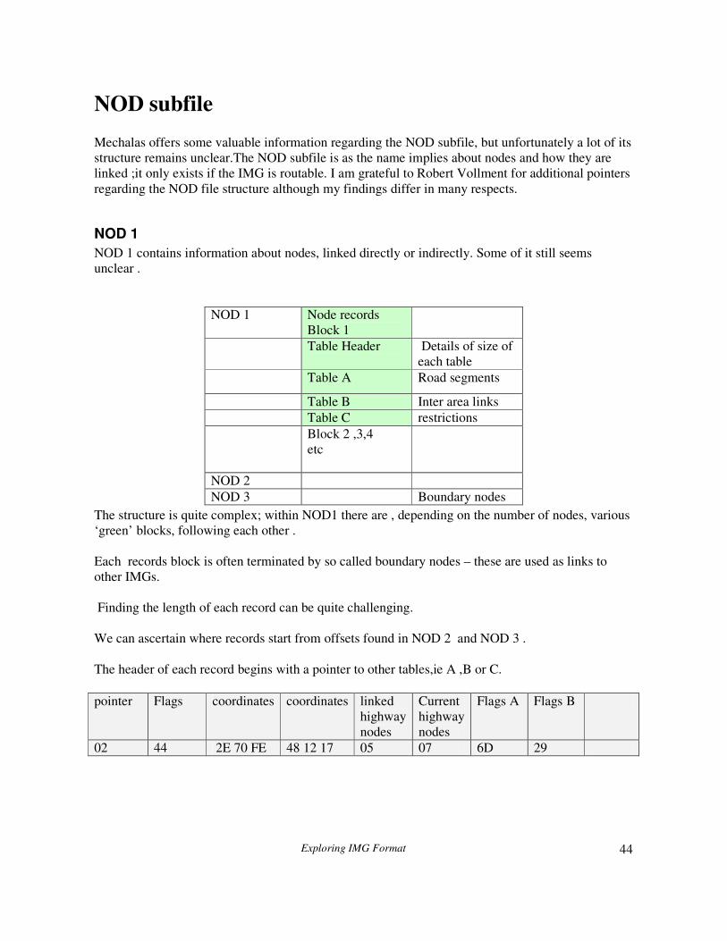
The structure is quite complex; within NOD1 there are , depending on the number of nodes, various
‘green’ blocks, following each other .
Each records block is often terminated by so called boundary nodes – these are used as links to
other IMGs.
Finding the length of each record can be quite challenging.
We can ascertain where records start from offsets found in NOD 2 and NOD 3 .
The header of each record begins with a pointer to other tables,ie A ,B or C.
NOD 1 Node records
Block 1
Table Header Details of size of
each table
Table A Road segments
Table B Inter area links
Table C restrictions
Block 2 ,3,4
etc
NOD 2
NOD 3 Boundary nodes
pointer Flags coordinates coordinates linked
highway
nodes
Current
highway
nodes
Flags A Flags B
02 44 2E 70 FE 48 12 17 05 07 6D 29

Exploring IMG Format
45
Pointer
The first byte points to the Tables Header – see below.
Flags at offset 1
There are several flags which are set to indicate special conditions
Mask Purpose
0 x 4
0 x 8 Marking a boundary
0 x 10 Marking a restriction
0 x 20 2 byte coordinates offsets instead of 3
0 x 40 Direct links
0 x 45
0 x 50
Any combination is possible but most frequently encountered are 44 or 4C
44= 40 + 4
4C = 40 + 4 + 8 , ie boundary nodes as found in NOD3
Direction Coordinates
These could be 2 or 3 bytes depending on Flag 0 x 10
Nodes Bytes
The two bytes after the coordinates indicate number of nodes in a highway as a multiple of 2 (?)
The first nodes byte contains the number of nodes ( as a multiple) of a linked highway ,ie
(5+1)/2=3
The second contains number of nodes in current highway: (7+1)/2 = 4
Flags A & B
Flag A is one byte and Flag B can be 2 bytes. Both also contain information showing bearings
between nodes.
Flag B
0 x 40 Inter area link
0 x 80 Last link
Flag A
0 x 7 Destination Class
0 x 38
0 x 40 Going Forward
0 x 80 New Direction

Exploring IMG Format
46
Tables Header
There can be several tables headers within NOD1.
An offset to a tables header is NOT found in the NOD header; instead it has to be calculated.
Presumably, this is because of the overwhelming number of nodes an IMG may contain.
Strangely each new ‘green’ block,except for the first one starts with a tables header.
To calculate the start of a tables header you need to add &40 to the end of a previous records block
and then find the nearest multiple of &40
Example: end of node records block :1C76
1C76 +40 = 1CB6
The next multiple of &40 is: 1CC0 so it starts at 1CC0
This is a 9 byte header:
00 01 02 03 04 05 Table A Table B Table C
coordinates Coordinates number number number
Number indicates number of records found in each table. Because each table contains records of a
fixed length we can calculate its total length and thus the beginning of the next node records block,
if any
Table A
0x00 3 Bits 0-29: Pointer to NET; bit 30: no delivery; bit 31: no emergency
0x03 1 Road class : bits 0-3: road speed; 4: oneway; 5-6: road class; 8: toll
0x04 1 RoadID
Each record has fixed length of 5 bytes:
00 00 13 00 12 RoadID = 18
00 00 13 00 20 RoadID = 32
00 00 13 00 2C RoadID = 44
01 00 13 00 3E
01 00 13 00 F3
00 00 03 00 32
00 00 11 00 44

Exploring IMG Format
47
NOD 2
It starts at NOD + &25 with length:NOD +&29
It does not appear to be accessed from any subfile.
0 1 2 3 4 5 6+
Road
classification
Offset into NOD1 mask Mask? Node
bitmap
Its length is generally 7 bytes but depends on the first and ‘blue’ mask byte.
If the mask’s value is >8 then an extra byte is added for every multiple of 8.
In addition, if bit 8 of the first byte is set, extra bytes highlighted in grey are added– see below.
Examples:
17 00 00 00 02 00 03
03 25 59 DB 01 00 04
25 87 00 00 08 00 FF
8B 5C 01 00 08 00 FF 04 14
87 1D 2D 03 0B 00 FF 06 04 12
BB B0 5B 00 14 00 E3 F7 0F 0C 09 40 00 0D 0E
25 82 61 00 09 00 FF 01
03 3F 1A 00 12 00 FF FF 03
For road classification see Mechalas .
Notice how offsets into NOD1 can show masks in the 3rd
byte, ie &DB - their significance is
uncertain.
Byte 4 acts as a mask for byte 5 or 6,ie gives you the number of bits to consider when examining
byte 5 (and?) or 6.
In our first example byte 6 contains 0x03 which in bits from LSB looks like 11000000.
The mask value (2) makes us consider only the first 2 bits, which could imply that this highway has
at least 2 nodes connecting to other highways, both of them set.
05 00 1B : 11011000
This would tell us to count the first 5 bits; the idea is that a node will be ignored if a bit is not set,ie
0, so we skip node 3.
If this is true then the maximum number of nodes can only be 8; to overcome this an extra byte is
added for each additional multiple of 8 – see last 2 examples

Exploring IMG Format
48
At present, the function of byte 5 is unknown but we surmise that the mask is 2 bytes long to allow
for values >255
0 1 2 3 4 5 6+
Road
classification
Offset into NOD1 mask Mask? Node
bitmap
04,08
,0C
If 8th
bit is set then the value after 0C signifies the length of extra bytes needed using a simple
algorithm: extra bytes = (value-1)/2
Example 0C 13 � (13 -1)/2 = 9
9B 13 08 00 13 00 7F FB 07 0C 09 42 00 28 30
A5 82 BE 01 17 00 F5 FF 7B 0C 13 41 00 15 16 17 18 19 1D 1E
The ‘red’ bytes are always ordered according to size. It is not clear what they mean.
Exploring IMG Format
49
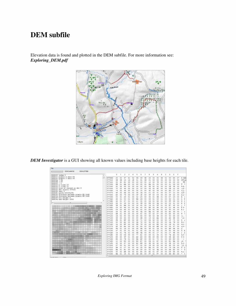
DEM subfile
Elevation data is found and plotted in the DEM subfile. For more information see:
Exploring_DEM.pdf
DEM Investigator is a GUI showing all known values including base heights for each tile.

Exploring IMG Format
50
Creating IMG files
There are several ways of creating an IMG file, each with its own personality:
1) using cgpsmapper
2) using MapTK
3) using mkgmap.jar
It all started with cgpsmapper, still in many ways the King , making full use of all the bitstream
parsing options, but unable to cope with extended elements and latest developments. It uses 8 bit
LBL encoding.
MapTK is quite a remarkable piece of software ; it produces IMG files from a text file and handles
extended elements,using 8 bit LBL encoding. It is struggling to keep up to date but its IMG files are
almost text book, ‘ ganz gründlich’ ie methodical.
By far the ‘neatest’ ,using fewer subdivisions and most up to date, is mkgmap created by a team of
programmers ; its IMGs are a delight to parse and highly recommended.
6 bit LBL encoding is used.
None of them can parse DEM subfiles.
NT POIs
The structure of NT pois is basically understood and similar to non NT pois. The only difference is
the data streams following the LBL / lat/lon blocks.
Such data streams do not have fixed lengths and Garmin is employing several tricks to define the
various lengths - more information on
www.pinns.co.uk/osm/garmin.html.

Exploring IMG Format
51
Extra POI data stream This consists of 3 or more bytes containing the ID as found in a TYP file - the maximum ID seems
to be &FFFF.
Each of the 3 bytes include masks the purpose of which is not clear. This also makes it very hard to
establish the extra poi ID.
IMG2TYP can display all IDs

Exploring IMG Format
52
bitstream, 28, 32, 33, 34, 36
cgpsmapper, 13, 36
Coordinates, 27
DEM, 1, 49
extended types, 17, 23
extra poi, 51
FID, 39
Garmin, 1
GMT, 5
header, 9
IMG, 1, 5, 7, 10
IMG Explorer, 5
IMG2TYP, 2, 6, 51
LBL, 18
left_shift, 35
Locked, 17
MapTK, 50
Mechalas, 5, 16, 21, 22
mkgmap, 50
NET, 1, 7, 18, 20, 21, 24, 30, 42
NOD, 7, 21, 30, 42, 43, 44, 46, 47
NT pois, 50
PID, 39
POI, 17, 18, 20, 22
polygons, 7, 8, 10, 12, 16, 24, 36
Polygons, 10, 26
POLYLINES, 24
RGN, 1, 7, 10, 11, 12
Subdivisions, 9, 13
TRE, 1, 10
TRE8, 41
types 0 x 100+, 25, 26