Exploratory Study of Basement Moisture During Operation of ... · Exploratory Study of Basement...
144
Exploratory Study of Basement Moisture During Operation of ASD Radon Control Systems December 6, 2007 Revised 3/10/08 Contractor Report to: U.S. Environmental Protection Agency Indoor Environments Division Washington, DC Under Cooperative Agreement No. XA83146010 by Bradley Turk Environmental Building Sciences, Inc. Las Vegas, New Mexico 87701 505-426-0723 [email protected] and Jack Hughes Southern Regional Radon Training Center Engineering Extension 217 Ramsay Hall Auburn University, Alabama 36849-5331 800-626-2703
Transcript of Exploratory Study of Basement Moisture During Operation of ... · Exploratory Study of Basement...

Exploratory Study of Basement Moisture During Operation of ASD Radon Control
Systems
December 6, 2007 Revised 3/10/08
Contractor Report to:
U.S. Environmental Protection Agency Indoor Environments Division
Washington, DC Under Cooperative Agreement No. XA83146010
by
Bradley Turk Environmental Building Sciences, Inc.
Las Vegas, New Mexico 87701 505-426-0723
and
Jack Hughes Southern Regional Radon Training Center
Engineering Extension 217 Ramsay Hall
Auburn University, Alabama 36849-5331 800-626-2703

Contractor Report to EPA: Basement Moisture & Radon During ASD 1 / 61
ABSTRACT
The technique most commonly used to control radon in buildings, active soil depressurization (ASD), has been investigated for its impact on basement moisture levels and ventilation. As part of an exploratory study, three houses near Harrisburg, Pennsylvania have been intensively monitored over an 18-month period for moisture indicators, radon levels, building operations, and other environmental parameters while ASD systems were cycled on and off. To implement this intensive monitoring program, novel protocols and study design were developed. A conceptual model suggested that the ASD systems can cause important changes in basement ventilation and interzonal air flows – therefore these parameters were periodically measured. Moisture levels were measured in walls and slab floors, indoor and outdoor air, surrounding soil, and wood framing members in the basement. The participating houses have unfinished basements: one having poured foundation walls, and the others having foundation walls of open and partially-filled concrete block. Results from these three houses indicate that ASD operation can produce significant moisture reductions in the basement air and walls, especially during non-summer months, and caused the predicted changes in air flow patterns. Both high and more typical flow and pressure configurations show this effect, although moisture reductions tend to be greater at higher system flows and pressures. Moisture reductions were diminished somewhat during the warm and humid summer months. Due to the long response time of moisture levels in foundation and soil materials, continuous operation of the ASD systems may cause greater reductions. The findings are consistent with anecdotal reports of drying and odor improvement in basements during ASD operation, and suggest that microbial growth may also be reduced. These effects may be different in other climates and house construction types.

Contractor Report to EPA: Basement Moisture & Radon During ASD 2 / 61
TABLE OF CONTENTS Executive Summary ................................................................................................................ 4 1. Introduction ..................................................................................................................... 12 2. Methodology ..................................................................................................................... 12
2.1 House Selection and Description ........................................................................... 12 2.2 Radon Mitigation Systems and Cycling ................................................................. 14 2.3 Dehumidifier ......................................................................................................... 14 2.4 Tests and Measurements ....................................................................................... 15
2.4.1 Instrumented Clusters ............................................................................. 15 2.4.2 General Building Conditions................................................................... 17 2.4.3 Interzonal Flows and Ventilation ............................................................ 17 2.4.4 Outdoor Conditions ................................................................................ 17 2.4.5 Periodic Testing and Measurements ........................................................ 17
2.4.5.1 House Air Leakage ................................................................... 18 2.4.5.2 Pressure Field Extension ......................................................... 18 2.4.5.3 Hand-held Instrument Measurements of Surface Moisture........ 19
3. Results and Discussion ..................................................................................................... 19
3.1 Conceptual Model ................................................................................................. 19 3.2 House Air Leakage ................................................................................................ 20
3.2.1 Internal Leakage ..................................................................................... 21 3.3 ASD System Operating Performance ..................................................................... 22 3.4 Pressure Field Extension Measurements ................................................................ 23 3.5 Ventilation and Interzonal Flow Measurements ..................................................... 23
3.5.1 Basement Air in ASD Exhaust ................................................................ 27 3.6 Indoor Radon Concentrations ................................................................................ 28 3.7 Basement Moisture ................................................................................................ 31 3.8 Hand-held Instrument Measurements of Surface Moisture ..................................... 49 3.9 Dehumidifier ......................................................................................................... 51 3.10 Moisture Extraction by ASD ............................................................................... 54 3.11 Estimated Energy Use ......................................................................................... 55
4. Summary and Conclusions .............................................................................................. 56
4.1 Recommendations ................................................................................................. 58
5. Acknowledgements .......................................................................................................... 59 6. References ........................................................................................................................ 59 7. Appendices
Appendix A - Report on Panel of Experts Meeting and Recommendations

Contractor Report to EPA: Basement Moisture & Radon During ASD 3 / 61
Appendix B - Forms, Logs, and Checklists Appendix C - House Selection Criteria Appendix D - ASD System Diagnostics, Design, and Description Appendix E - Monitoring and Testing Techniques and Instrumentation Appendix F - Description of Electronic Data Files Appendix G - Conceptual Model: Impact of ASD Operation on Basement Moisture
Conditions Appendix H - Summary of 14-Day Mean Daily Moisture Changes Appendix I - Summaries of Handheld Surface Moisture Measurement Data

Contractor Report to EPA: Basement Moisture & Radon During ASD 4 / 61
EXECUTIVE SUMMARY Background
For years, those involved with radon mitigation in buildings have reported that operation of active soil depressurization (ASD) radon control systems appears to reduce moisture levels in the basements of some houses. These systems inhibit advective radon entry by reversing the air pressure gradient between the soil and house substructure. Reductions in musty and moldy odors, drying and shrinkage of materials in the basement, and less dampness in the basement have all been reported. Because of a demonstrated link between dampness in houses and respiratory problems, the ability to control indoor moisture as well as radon and other soil gas pollutants has important public health ramifications.
Although it has been speculated that ASD systems interfere with air movement that can carry moisture into substructures, and with capillarity and diffusion from the soil, there is little relevant information on ASD-caused moisture changes in buildings. To fill the research void, an exploratory project was initiated to investigate this phenomenon and to determine if ASD may be a beneficial multi-pollutant control technique. This approach was also evaluated as an energy efficient alternative or adjunct to dehumidifier use.
Study Design
A panel of experts was convened to formulate recommendations for the study design, experimental protocols, and measurement and testing techniques. These recommendations led to the development and implementation of innovative approaches to long-term monitoring of moisture and air movement in the project houses.
The panel also recommended development of a simple conceptual model for understanding moisture movement and the flow paths of water vapor-laden air within a building, between the building and outdoors, and through the soil near a building under the influence of an ASD system. This conceptual model identified the importance of drying that is caused by ASD operation altering three classes of increased air flows in and around a basement, including:
1) Air from outdoors enters the basement by several pathways and is then exhausted by ASD.
2) Basement air is pulled into the surrounding soil, then is exhausted by the ASD. 3) Outdoor air is pulled directly to the ASD suction point through the surrounding soil and
is then exhausted by the ASD. In order for drying of the basement air and materials to occur, the entering air must be drier than the materials or basement air that it replaces.
Using data representative of houses and outdoor conditions near Harrisburg, PA (with or without an ASD system operating), it was estimated that moisture contributions from air flows from outdoors, first floor, and soil (approximately 50 ft3/min, 0.024 m3/s) to the basement could be greater than 25 kg/day. It was also estimated that less than 2 kg/day is due to diffusion through 1500 ft2 (139.5 m2) of poured concrete walls and floors. Diffusion becomes more important when the ventilation rates are low and when permeability of the materials is higher (e.g., block walls). It is likely that these mechanisms work in combination, to varying degrees, depending on many house, soil, and meteorological conditions.
From a large number of candidates, three homes near Harrisburg, PA were selected for the field study. The homes were required to meet a number of criteria, including elevated basement radon levels, occupant-reported dampness problems, and basements that were mostly

Contractor Report to EPA: Basement Moisture & Radon During ASD 5 / 61
unoccupied, unfinished, and had concrete slab floors. During the house selection process, it was noted that the majority of the houses with occupant complaints of moisture problems in the basement also had block wall foundations. Therefore, two of the three study houses had open, or partially-filled, concrete block foundation walls, while one house had poured concrete walls. All houses had central forced air heating and cooling (HAC) equipment located in the basement. ASD Systems
Following baseline testing and monitoring, ASD radon mitigation systems were installed in each house. Each system was constructed of an in-line exhaust fan connected to 3 or 4 inch PVC pipe that 1) penetrated the slab floor, 2) was attached to pre-existing passive radon control systems, or 3) penetrated into the open core of the block walls (house PA03 only, and is commonly referred to as block wall ventilation – BWV). When the systems are activated, the exhaust fan depressurizes and draws air from the soil and materials surrounding the basements, thereby limiting radon entry. To accentuate changes in moisture levels, the ASD systems were designed for research purposes with more options for changes in flow/pressure and configuration, compared with typical radon mitigation systems. Several configurations of the systems were cycled on and off over 1- to 14-day periods for 12 to 18 months.
The operating characteristics of the ASD systems were continuously monitored throughout the study, including during the ‘full’ system and single-pipe configurations. Static pressures developed by the ‘full’ systems ranged from 46 to 210 Pascal (Pa). Single-pipe pressures ranged from 74 to 210 Pa. Total system flows were from 85 cfm to 180 cfm for the ‘full’ system, and 62 cfm to 90 cfm for the single-pipe configurations. Time constraints did not allow for evaluation of other configurations of suction pipes and even lower operating pressures and flows.
Pressure Field Extension – To determine the extent of the depressurization caused by the ASD systems, the air pressure difference (∆P) between the basement air and the exterior of the foundation walls and floor was measured several times throughout the study. Measurements made at 14 to 20 test holes showed that operation of the ASD systems caused robust ∆P that extended to all areas of the slab floor: typically ranging from -18 to -60 Pa for full ASD operation, and -15 to -44 Pa when ASD was in single-pipe configuration. The ∆P across the walls was not as uniform as the sub-floor PFE, with ∆P generally less than -1 Pa at many locations. Operation of the HVAC equipment appeared to have minimal impact (less than 1 Pa) on wall and floor ∆P during the pressure field measurements. Air Leakage, Interzonal Flows and Ventilation
Air movement between the basement and outdoors, upstairs, and soil was periodically measured using a constant-injection, automated collection, perfluorocarbon tracer (PFT) gas system. Results indicate that the ASD systems tend to increase the air flow from all sources (outdoors, upstairs, and soil) into the basements. This is likely caused by basement air being pulled into the ASD pipes through cracks and openings in the foundation, thereby slightly depressurizing the basement, and being replaced with air from upstairs and outdoors. However, other than in house PA02, this additional depressurization of the basement was not measurable with ASD systems on. Outdoor air ventilation rates (infiltration) tended to be much lower in the basements than upstairs for two of the houses, while ASD operation caused large increases (60% to over 200%) in the ventilation rates – for both the basement and upstairs at two houses. Tracer measurements also determined that between 46% and 72% of the air in the ASD discharge

Contractor Report to EPA: Basement Moisture & Radon During ASD 6 / 61
originated in the basement, presumably, as described above, through openings in the foundation materials.
Air leakage of various portions of the building envelope was measured with a blower door. The calculated normalized leakage areas (NL) for all three houses are atypically low (0.113 to 0.543) when compared to other, similar houses. Determinations of the basement ceiling equivalent leakage areas (ELAc) show the presence of potential pathways between the upstairs and basement for air to flow (0.027 m2 to 0.088 m2). Continuous, Multi-parameter Monitoring
In order to evaluate the untried testing and measurement techniques employed in this study, and to be assured that important changes in building moisture and other characteristics were observed, a comprehensive and novel monitoring and testing protocol was developed and implemented. Over 115 parameters in and around each house were semi-continuously monitored using an array of sensors. These included temperature, humidity air pressure differentials, radon concentrations, and meteorological conditions.
To characterize moisture movement and storage in foundation walls and floors, measurement clusters were installed at four wall and two slab locations of each house. Each cluster consisted of temperature/relative humidity (RH) sensors embedded at three depths in the material, and calibrated wood moisture sensors installed at two depths. Indoor Radon Concentrations
All houses experienced large reductions in indoor radon levels, regardless of system configuration – even approaching levels in the outdoor air. Radon concentrations, with ASD off, on the 1st floor of these houses were approximately 25 to 50% of the basement concentrations, which is typical for houses with HAC systems. These data indicate that the primary source of radon for these houses was pressure-driven entry from the soil.
Basement Moisture
Over the 10- to 15-month duration of system cycling, the dominant trend in the basement air RH tracks the outdoor air moisture levels. Closer inspection of the time series data suggests that the basement RH does change in response to many of the periods of ASD operation, but that this response is superimposed on the larger and longer seasonal changes in outdoor air moisture. These data also hint that ASD-caused moisture responses are more muted and less predictable in the summer months.
Analysis of changes in moisture included 1) comparison of mean RH and 2) autoregression to determine the daily rate of change in RH as the ASD systems were cycled on and off. Mean RH data were from Day 7 – 14 from the 14-day, and longer, cycle periods. The data indicate that, for many of the foundation materials, a much longer ASD on or off period will be required before quasi-equilibrium is reached. The autoregression was performed on the first seven days (and in a subsequent analysis, 14 days) of seven day and longer periods.
The mean RH reduction in basement air ranged from 4% (PA01) to 10% (PA03) during full ASD cycling in the non-summer periods. Reductions during the warm and humid summer months, when moisture control was most needed in these houses, were much smaller or negligible. Operation of the single-pipe ASD systems with more typical flows and pressures caused smaller, but still significant, reductions in basement air RH as compared to full system operation.

Contractor Report to EPA: Basement Moisture & Radon During ASD 7 / 61
In contrast to the basement air RH, the equilibrium RH for most locations within the block cores and within approximately two cm of the interior surface of the blocks display large and dramatic changes as the ASD is cycled during the non-summer months, ranging from 18% to 30% RH. This drying effect is likely due to greater air flow induced by the ASD systems through the open cavities and porous block materials. It is not clear that the Interior and Core locations of the block walls reached steady state conditions even after two weeks of operation. Although the ASD system causes reductions of almost 30% RH in block walls when outdoor moisture levels are low, the response is dampened during the more humid summer months. Comparison with the single-pipe, sub-slab configuration at one house clearly shows that block wall ventilation component of the ASD system had a large impact on wall moisture at this house.
Poured wall locations exhibit behavior more like that of the slab floors, where moisture levels at all houses experienced much smaller responses to changes in ASD operation – generally less than 3% RH. The trend for most wall and floor locations is for the equilibrium RH to increase with depth into the wall or floor material. While the shallower test locations are often more responsive to ASD cycling and track with changes in basement air moisture, there are exceptions. For example, although some block wall cores have high baseline (ASD off) moisture levels, they show larger reductions than the Interior locations when the ASD is on. And several “Thru-slab” locations also have large reductions on equilibrium RH during when the ASD is running. These results indicate that the ASD systems are causing comparatively large changes in flow of air with low water vapor pressure, at these locations. The locations on the exterior surface of the walls are often very wet or saturated (causing the failure of many moisture sensors), and typically do not have an observable response to the ASD operation.
Hand-held Instrument Measurements of Surface Moisture
At the same time that the intensive moisture monitoring protocol was being conducted, another simpler method using hand-held instruments was also being performed on four to five occasions throughout the study. The purpose of these measurements was to evaluate and compare the measurement approaches.
To conduct these measurements, variable-spacing grids were laid out and marked with removable tape on both the floor and the walls. This resulted in between 51 and 55 floor measurement locations, and 80 to 120 wall locations for the each of the three houses, depending on size, layout, and obstructions.
The hand-held device used for determining surface moisture on the basement floors and walls would measure moisture within approximately the first ½” of the material. Moisture in the wood joists of the basement ceiling was measured using a hand-held, pin-type meter that detected the electrical resistance between the two sharp prongs inserted into the joists parallel to the grain.
Measurements of the moisture content in the joists of the basement ceiling and at the surface of the walls and floors tend to track the moisture in the basement air and within the basement-facing foundation surfaces.
The surface measurements also indicate that the moisture content of the slab floors tends to be higher than that for the walls, with the slab floor at PA01 having the highest overall moisture levels (Table 8). This is surprising given that conditions in the basement of PA01 tended to be the driest of all houses throughout the study.

Contractor Report to EPA: Basement Moisture & Radon During ASD 8 / 61
Dehumidifier Dehumidifiers are the most common method used by homeowners for removing moisture
from basements, however, they can be large energy consumers. To compare the performance of the ASD technique to dehumidifier use, a medium efficiency dehumidifier was added to the cycling protocol at one house for three cycling periods from July to October 2006. Condensate production, energy use, and unit on-time were recorded during their operation. The unit was operated on demand by a built-in humidistat set to 50% RH. The dehumidifier showed dependable and stable moisture reductions in the basement air for all three cycles, but did not reduce the basement air RH to 50% during the first cycle (and neither did the ASD system during a contiguous time period). It appeared to have no impact on the moisture in the block wall core, nor, of course, did it affect indoor radon levels. Conversely, the full ASD configuration with wall extraction pipes had a larger impact on air within the block than the air in basement. The dehumidifier operated approximately 70% of the time during the first cycle, declining to 47% of the time during the last cycle
The quantity of water extracted from the air by the dehumidifier steadily declined from 3.5 gal/day (13.4 L/day) during the first cycle to 0.9 gal/day (3.6 L/day) during the last cycle. Using the flow rate and moisture concentration in the ASD pipes for the corresponding ASD on periods, calculations determined that the water extracted by the ASD system declined from 13.8 gal/day (52.2 L/day) to 12.7 gal/day (48.1 L/day). These results indicate that the ASD systems are probably mining moisture from sources other than the basement air alone. The most likely source is the wet/damp soil surrounding the foundation that is constantly being replenished due to poor drainage conditions.
Moisture Extraction by ASD
The average moisture extracted by the full ASD system configuration ranged from approximately 13 to 19 gal/day, while the single-pipe systems extracted approximately 10 to 13 gal/day. These data are averages of one or more seasons. A preliminary inspection of the data indicates that moisture removal during the summer is higher than for winter, for the same configuration. ASD Energy Use
Estimates of energy to operate the ASD system fan and condition additional outdoor air ranged from $83 to $191 per year for these houses, while energy for a typical dehumidifier would cost approximately $180. This energy will be required for ASD systems installed to control indoor radon, and the extra benefit of moisture reduction piggybacks on the energy necessary for radon control. While the ASD systems in these houses may not eliminate the need for dehumidification during warm and humid periods of summer, they may reduce the moisture load in the basement and usage of the dehumidifier.
Summary and Conclusions
As the first systematic and intensive study of moisture changes in buildings caused by operation of ASD systems, normally used for indoor radon control, this project broke new ground by developing novel design and monitoring protocols and applying them over 12 – 18 months in a group of three homes. The project has also created a large data set on how ASD systems function and their impact on moisture in homes.

Contractor Report to EPA: Basement Moisture & Radon During ASD 9 / 61
The primary finding of this project has been that ASD systems caused statistically significant and beneficial reductions in moisture levels and dampness in the basements of three Pennsylvania houses in the non-summer months. During the warm and humid summer months, when dehumidifiers are typically needed in these homes, overall changes in building moisture with the ASD operating were much smaller or negligible, and of less practical importance. ASD-caused moisture responses in the basement air were observed to be secondary to and superimposed on the larger trend of the basement air moisture to track outdoor air moisture levels. Block wall surfaces facing the basement, and especially block cores, showed the largest moisture reductions during ASD operation – possibly because the porous blocks permit greater air flow that dries the materials. Moisture changes in slab floors and poured walls were smaller and occurred more slowly than in porous block walls, and may require longer cycle periods to show a significant change. Since the foundation walls and floors of these homes were generally not finished, moisture changes in the micro-environments of furred wall cavities and beneath carpet were not examined. However, it is possible that ASD operation could have a relatively larger impact on moisture levels and microbial growth in these moisture sensitive materials, by increasing the flow of drying air, and reducing moisture ingress from diffusion and convective air movement. Robust system configurations, with more suction points and higher air flows and pressures than typical installations, produced larger moisture reductions. When configured for more typical flows and pressures, the systems caused smaller, but encouraging, moisture reductions. The effects were apparent in the basement air and walls of all three houses, and in the slab floor of two houses.
A number of innovative measurement protocols and techniques were evaluated and employed to monitor moisture and ventilation flows in houses. These included a novel adaptation of the constant injection, multi-PFT ventilation measurement technique, and long-term continuous monitoring of many environmental parameters, including moisture in the basement walls and floors and ASD exhaust. To evaluate the value of simpler and less-costly measurements techniques, handheld instrument measurements of moisture were conducted periodically over an extensive grid of locations in the basements, These handheld measurements within the interior surfaces of foundation materials track continuous measurements with sensors embedded within approximately the first two centimeters of the surface, and with measurements of moisture in the basement air. This approach may be an effective replacement in future studies for the intensive monitoring protocols used in these three houses. Additional work is required to study the relationship between these surface measurements and moisture stored at depth within the foundation materials.
Consistent with the guidance of the conceptual model, interzonal flow testing and results suggest that quantity of air drawn into the basement from upstairs and outdoors increases during ASD operation. In the non-summer months, this comparatively low moisture air can cause drying of the basement air and foundation materials. Under these conditions, it may be possible to reach a minimum moisture level, below which little additional drying will take place. Conversely, in the summer, the systems have the potential to add moisture to the basement by drawing in warm humid air from outdoors – while at the same time pulling in dry conditioned air from upstairs (in buildings with air conditioning). The ratio of the air leakage from outdoors to air leakage from the upstairs may be an important factor in determining the success of ASD moisture reduction in humid climates during the summer. The amount of air leakage from the soil through openings in the foundation surfaces is probably another important factor that influences the moisture-reducing performance of ASD systems.
Contractor Report to EPA: Basement Moisture & Radon During ASD 10 / 61
With the ASD systems operating, outdoor air ventilation rates were boosted both in the basement and upstairs. When the systems were off, basement ventilation rates at all houses often fell below the requirements of ASHRAE Standard 62.2 (2007), while the upstairs ventilation rates often did not meet the minimum at PA01 and PA02. Therefore, the ASD systems tend to act as whole house exhaust ventilation in these three houses and could provide additional indoor air quality benefits, albeit at the cost of conditioning the incoming, outdoor air. Care must be taken with exhaust ventilation systems not to depressurize the building, causing combustion appliances to backdraft or other contaminants to be drawn into the occupied spaces. All of the houses participating in this study had sealed-combustion furnaces and hot water heaters with power-vented draft inducers, and wouldn’t be vulnerable to backdrafting. As mentioned above, exhaust ventilation systems can also draw in humid outdoor, that may add unwanted moisture to the building air and materials.
In houses with bulk water entry (as in the case of PA03), ASD systems are probably not well-suited to control the resulting dampness and moisture accumulation. However, few remedial techniques can successfully address this issue. The best solution is to correct the source of water.
Portable dehumidifiers are currently one of the most common methods for seasonal control of moisture in basements and crawlspaces. A dehumidifier used for three months in one study house produced stable reductions in basement air RH, but had little impact on moisture in the block walls and slab floor. This may be an important consideration for finished walls, since, by contrast, the ASD system tended to reduce moisture in block walls. The dehumidifier extracted approximately 8% to 25% of the moisture removed by the ASD system. Presumably, the dehumidifier removed moisture primarily from basement air, while the ASD system pulled moisture from the air as well as from the foundation and materials surrounding the foundation.
Estimates of additional energy usage during ASD operation show increases from $79 to $164 per year for these houses. These costs may be representative of many ASD systems installed to control indoor radon. However, the data suggest that ASD operation may also reduce dehumidifier usage during the warm, humid summer months and may reduce the overall energy bill in houses with a radon problem and where a dehumidifier is being used at least 5 months out of the year.
Concerns over drying, and subsequent shrinkage and settling, of materials around the foundation were not addressed in this study.
Recommendations
It is not known whether the moisture and ventilation findings for these three houses apply to other houses in other regions. There appear to be many factors that could affect the effectiveness of ASD in reducing substructure moisture, and additional investigation is necessary to address these issues. This study was a good investment for future research. Some recommendations for this further work include:
• Conduct national survey of moisture in houses to identify vulnerable house construction and climates
• Examine the relationship between outdoor conditions (RH and precipitation) and ASD system effectiveness.
• Using information from this study, enhance and refine the conceptual model to forecast ASD moisture performance in other climates, house construction and soil types, incorporating air leakage areas and locations, house construction features and HAC systems, and climate characteristics

Contractor Report to EPA: Basement Moisture & Radon During ASD 11 / 61
• Design and conduct investigation of ASD impact on building moisture in other climates, soil types, house foundation types, and mechanical cooling.
• Further explore less-intensive testing and measurement protocols so that evaluations of moisture control by ASD can be more easily and economically conducted in other houses.
• Monitor moisture levels during longer periods of ASD operation. • Conduct extended, four season evaluation of additional configurations of ASD systems,
with a wider range of operating flows and pressures and suction point placement. • Consider what, if any, design and installation changes would improve moisture control
capabilities of ASD systems. • Examine the ASD-caused moisture changes in moisture sensitive materials and
assemblies that are commonly installed to finish basement floors and walls: wood framing, gypsum board, paneling, carpet, etc.
Contractor Report to EPA: Basement Moisture & Radon During ASD 12 / 61
1. INTRODUCTION
For years, those involved with radon mitigation in buildings have reported that operation of active soil depressurization (ASD) radon control systems appears to reduce moisture levels in the basements of some houses (Turk and Harrison 1987; Brodhead 1996). These systems inhibit advective radon entry by reversing the air pressure gradient between the soil and house substructure. Reductions in musty and moldy odors, drying and shrinkage of materials in the basement, and less dampness in the basement have all been reported.
The development and exacerbation of asthma, along with other respiratory ailments, has been related to damp indoor environments and dampness-dependent exposures to fungi and house dust mites (Fisk et al 2007; IOM 2000; IOM 2004; Mannino et al 1998). Mudarri and Fisk (2007) estimate that approximately 21% of all asthma cases in the U.S are attributable to dampness and mold exposure in homes. Other studies have specifically shown an association between damp basements and respiratory health symptoms (Brunekreef et al 1989; Dales et al 1991; Spengler et al 1994), and respiratory symptoms in children with dampness in housing (Jaakola et al 1993; Williamson et al 1997). Because of this link between dampness in houses and respiratory problems, the ability to control indoor moisture as well as radon and other soil gas pollutants has important public health ramifications.
The U.S. EPA Environmental Protection Agency (U.S. EPA) Indoor Environments Division conducted a literature review, but found little, relevant, published information on systematic studies of ASD-caused moisture changes in buildings. Although there can be many sources of dampness in basements, it has been speculated that ASD systems interfere with air movement that can carry moisture into basements (and other substructures), and with capillarity and diffusion from the soil. Therefore, the U.S. EPA funded an exploratory project through Auburn University to investigate this phenomenon and to determine if ASD may be a beneficial multi-pollutant control technique. This approach may also be more energy efficient than the use of dehumidifiers. Preliminary results on this project have been reported earlier (Turk et al 2007), but expanded findings of this work are presented here. 2. METHODOLOGY
Only limited, pre-existing information was available on study design, experimental protocols, and measurement and testing techniques for investigating the impact of ASD operation on moisture in buildings. Therefore, a panel of experts in moisture control, radon entry and mitigation, and building science was convened by the U.S. EPA to draft a research plan for this project. A majority of their recommendations were incorporated into the experimental design. Their overall recommendations were for the development of a conceptual model, evaluation of test and measurement methods, and a focused field test and measurement study in a small number of houses. A report on the guidance and recommendations is found in Appendix A. Primary forms, logs, and checklists that were used during the study are included in Appendix B. 2.1 House Selection and Description
Funding limits precluded designing and constructing a research house that would allow control over many of the parameters expected to influence moisture entry, accumulation, and removal. As a result, occupied houses with full basements were solicited, surveyed, and screened as candidates for study. To enhance the possibility that moisture changes could be
Contractor Report to EPA: Basement Moisture & Radon During ASD 13 / 61
detected in the resulting data, the houses had to meet a number of criteria. Critical criteria included:
• owner-occupied (or unoccupied) single-family, detached residence • full-depth basement beneath the entire house • expected residency of 18 months • evidence of persistent moisture entry (dampness) into the basement • no liquid water entry or unusual moisture sources • unoccupied and mostly unfinished basement • at least one house with poured basement walls • no subsurface, karst-like features (water-formed cavities in rock) affecting basement
floors or walls With some exceptions, most of these criteria were met by the study homes. Additional
criteria were also considered in selection of the houses, but were not essential for participation. The complete listing of criteria and rationale for applying the criteria are included in Appendix C.
The house selection process involved contacting prospective participants through newspaper advertisements, state and local building code departments, developers and builders, and word of mouth. The following steps were then taken to screen for suitable study candidates.
• Conduct a phone interview with the homeowners, using one of several versions of a phone interview checklist
• During a house visit to gather additional information on prospective homes, the following activities were conducted:
Meet with and interview occupants Sketch floor plan with overall dimensions Complete house characteristics checklist Photograph house interior and exterior Conduct moisture meter survey of basement (walls, floor, joists and framing) Measure indoor and outdoor temperature/relative humidity Conduct short-term measurement of radon concentrations in the house
The final selection was based on a number of factors, including interest of homeowners, access to house and lifestyle factors, compliance with critical criteria, and evidence of measurable moisture levels.
Three homes near Harrisburg, PA were finally selected. The homes had elevated basement radon levels, occupant-reported dampness problems, and basements that were mostly unoccupied, unfinished, and had concrete slab floors. During the house selection process, it was noted that the majority of the houses with occupant complaints of moisture problems in the basement also had block wall foundations. Therefore, two of the three study houses had open, or partially-filled, concrete block foundation walls (PA02 and PA03), while one house had poured concrete walls (PA01). Although the houses were selected so as not to have bulk water entry, two of the houses were later discovered to have minor water leaks through basement walls (PA02 and PA03), and drainage problems around the outside of building (PA03). All houses had central forced air heating and cooling (HAC) equipment located in the basement. House ages at the beginning of the study were 3 years (PA01), 8 years (PA02), and 35 years with a 31 year-old addition (PA03). Humidification equipment attached to the HAC was disabled during the study,

Contractor Report to EPA: Basement Moisture & Radon During ASD 14 / 61
although room-sized dehumidifiers were permitted in the bedrooms on the first or second floor. The upstairs of the houses were one story (PA02) or two stories (PA01 and PA03) in height and of frame construction. 2.2 Radon Mitigation Systems and Cycling
To establish pre-mitigation conditions and operating characteristics in each house, a two- to three-month period of baseline testing and monitoring was conducted. The tests and measurements during baseline were identical to those performed in the remainder of the study, and are described below. After the baseline period, ASD radon mitigation systems were installed in each house. Flow and pressure were predicted for each system through a systematic evaluation of the flow and pressure characteristics of the materials surrounding the foundation walls and below the slab floors. These ‘diagnostic’ protocols and results were used to design the ASD systems.
Each system was constructed of an in-line exhaust fan connected to 3 or 4 inch PVC pipe that 1) penetrated the slab floor, 2) was attached to pre-existing passive radon control systems, or 3) penetrated into the open core of the block walls (house PA03 only, and is commonly referred to as block wall ventilation – BWV). When the systems are activated, the exhaust fan depressurizes and draws air from the soil and materials surrounding the basements, thereby limiting radon entry. To accentuate changes in moisture levels, the ASD systems were designed for research purposes with more options for changes in flow/pressure and configuration, compared with typical radon mitigation systems. Since this project was intended as a ‘proof-of-concept’, the systems were initially operated at higher flows and pressures than in commonly installed systems. To evaluate the moisture response time of the house and surrounding materials, and to provide ‘control’ conditions for evaluating system performance, the systems were cycled on and off over 1- to 14-day periods over four seasons as multi-parameter testing and monitoring was conducted. Several longer, non-cycled, periods of operation were also evaluated during the 12- to 18-month field study. After approximately twelve months, the ASD systems were modified to be more representative of a typical system installation. This usually involved disabling one or more suction points/pipes, and reducing flow in the remaining single pipe that pulled air from below the slab floor. The reduced flows in the single pipes at PA02 and PA03 were still higher than for most installations. However, this would have occurred even with standard system fans because of the low resistance to air flow for these systems. These modified, or reduced operation, systems were also cycled on and off. Holes, large cracks, and joints in the foundation walls and floor were sealed as part of the mitigation process – and in house PA01, the wall/floor joint was sealed as a staged element of mitigation approximately six months after mitigation systems were installed. A more complete description of the diagnostic protocols and installed ASD systems is included in Appendix D.
2.3 Dehumidifier
During the house selection process, most of the homeowners who reported moisture problems in their basements used portable dehumidifiers to control that moisture during the summer. However, dehumidifiers can be large energy consumers depending on their efficiency and the amount of moisture in the space where they are located. To compare the performance of the ASD technique to dehumidifier use, a dehumidifier was added to the cycling protocol at house PA03 from July to October 2006. A medium efficiency dehumidifier (an energy factor of 1.6L/kWh) was purchased from a major home retailer and installed on an elevated platform so

Contractor Report to EPA: Basement Moisture & Radon During ASD 15 / 61
that condensate produced by the unit could be captured and measured during the weekly house visits. Energy use and unit on-time were monitored with a current transformer connected to the dehumidifier power cord and to one of the on-site data loggers. 2.4 Tests and Measurements
In order to evaluate the untried testing and measurement techniques employed in this study, and to be assured that important changes in building moisture and other characteristics were observed, a comprehensive monitoring and testing protocol was developed and implemented. Over 115 parameters at each house were semi-continuously monitored using an array of sensors. These sensors were scanned every 30 seconds and measurements recorded hourly by on-site data loggers (Campbell Scientific, models 21X and 10X). The houses were visited at least once per week to conduct tests, adjust ASD system operation, and download data. Monitoring and testing instruments and techniques are summarized in Appendix E. Results from a subset of the parameters monitored are reported here.
Data collected by the data loggers were subsequently processed to 1) remove erroneous values caused by sensor failure, power outages, or other acquisition system failure, 2) converted to engineering units, and 3) compiled into single, large Microsoft Excel spreadsheets. Where appropriate, data from measurements using hand-held instruments was also coded into spreadsheet formats. These data files are briefly listed and described in Appendix F.
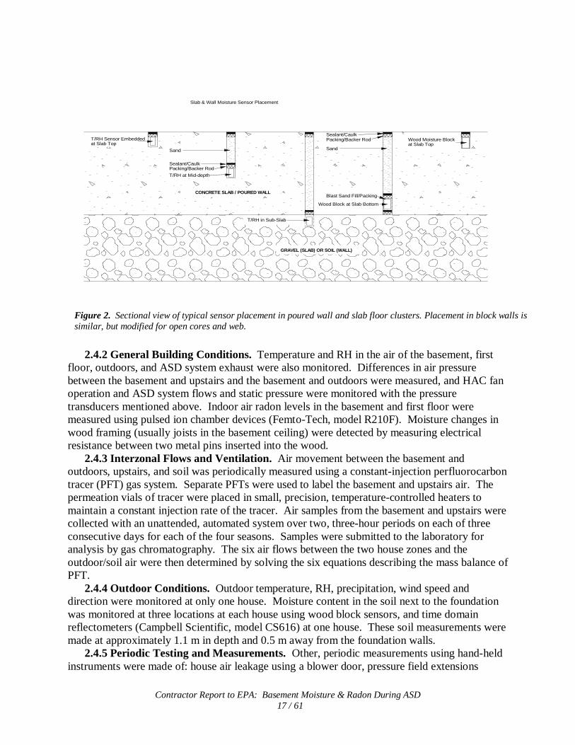
2.4.1 Instrumented Clusters. To characterize moisture movement and storage in foundation walls and floors, measurement clusters were installed at four wall and two slab locations of each house. Each cluster consisted of temperature/relative humidity (RH) sensors embedded at three depths in the material, and experimental moisture sensors, made from calibrated wood dowel blocks, installed at two depths. Figures 1 and 2 show the typical layout and sectional views of the clusters for poured walls and slab floors. Sensor placement in block walls was altered so that the ‘Interior’ sensor (embedded in the block wall approximately 2 cm from the basement-facing surface) was placed in the block webbing, and the ‘Middle’ sensor was in the open block cores.

Contractor Report to EPA: Basement Moisture & Radon During ASD 16 / 61
Temperature was measured with a thermistor, while RH was measured with a heated,
variable-capacitance sensor. Temperature and RH sensors were packaged together in a sleeve of spunbonded polyethylene fabric that is water resistant, but vapor permeable. The wood probes sense changes in electrical resistance between two metal pins in the wood as moisture levels change. Basement-soil air pressure differences were also measured at each cluster with a transducer employing a variable-capacitance diaphragm (Setra, model 264). Radon levels were monitored semi-continuously by alpha scintillation cell technology (Pylon, model AB-5) through the foundation material at one floor and one wall cluster as an indicator of soil gas movement.
Figure 1. Plan view of the typical pattern of sensor placement for instrumented clusters in poured walls and slab floors (dimensions are in inches). See Figure 2 for sectional view of sensor placement.
T/RH (Top)
T/RH (Middle)
T/RH (Gravel or Soil)
Wood Block (Top)
Wood Block (Bottom)
6.00
6.00
4.24
Contractor Report to EPA: Basement Moisture & Radon During ASD 17 / 61
T/RH Sensor Embedded
Sand
Sealant/CaulkPacking/Backer Rod
T/RH at Mid-depth
at Slab Top
T/RH in Sub-Slab
Sealant/CaulkPacking/Backer Rod
Sand
Blast Sand Fill/Packing
GRAVEL (SLAB) OR SOIL (WALL)
CONCRETE SLAB / POURED WALL
Wood Block at Slab Bottom
Wood Moisture Blockat Slab Top
Slab & Wall Moisture Sensor Placement
2.4.2 General Building Conditions. Temperature and RH in the air of the basement, first
floor, outdoors, and ASD system exhaust were also monitored. Differences in air pressure between the basement and upstairs and the basement and outdoors were measured, and HAC fan operation and ASD system flows and static pressure were monitored with the pressure transducers mentioned above. Indoor air radon levels in the basement and first floor were measured using pulsed ion chamber devices (Femto-Tech, model R210F). Moisture changes in wood framing (usually joists in the basement ceiling) were detected by measuring electrical resistance between two metal pins inserted into the wood.
2.4.3 Interzonal Flows and Ventilation. Air movement between the basement and outdoors, upstairs, and soil was periodically measured using a constant-injection perfluorocarbon tracer (PFT) gas system. Separate PFTs were used to label the basement and upstairs air. The permeation vials of tracer were placed in small, precision, temperature-controlled heaters to maintain a constant injection rate of the tracer. Air samples from the basement and upstairs were collected with an unattended, automated system over two, three-hour periods on each of three consecutive days for each of the four seasons. Samples were submitted to the laboratory for analysis by gas chromatography. The six air flows between the two house zones and the outdoor/soil air were then determined by solving the six equations describing the mass balance of PFT.
2.4.4 Outdoor Conditions. Outdoor temperature, RH, precipitation, wind speed and direction were monitored at only one house. Moisture content in the soil next to the foundation was monitored at three locations at each house using wood block sensors, and time domain reflectometers (Campbell Scientific, model CS616) at one house. These soil measurements were made at approximately 1.1 m in depth and 0.5 m away from the foundation walls.
2.4.5 Periodic Testing and Measurements. Other, periodic measurements using hand-held instruments were made of: house air leakage using a blower door, pressure field extensions
Figure 2. Sectional view of typical sensor placement in poured wall and slab floor clusters. Placement in block walls is similar, but modified for open cores and web.

Contractor Report to EPA: Basement Moisture & Radon During ASD 18 / 61
(PFE) developed by the ASD systems, and near-surface moisture over a 1- to 2-meter grid on the basement floor and walls, and wood joists of the basement ceiling.
2.4.5.1 House Air Leakage – A set of three blower door procedures was employed at each house. Each procedure was a multi-point depressurization test, with house pressures ranging from -60 Pa (where achievable) to -15 Pa or less, in 5 Pa increments. At each house pressure, fan pressure was recorded and converted to flow using the tables in the blower door manual. A power curve was fitted to house pressure and blower flow data, and the curve formula utilized to predict flow at 4 Pa (and in the case of PA03, the flow at 50 Pa). The 4 Pa and 50 Pa flow values were used to calculate the air changes per hour (ACH50 and 4) and effective leakage area (ELA4). The normalized leakage (NL) was also calculated, using ELA, gross floor area, building height, and a reference height of 2.5 m (8 ft).
Blower location, house configuration and depressurized area for the three procedures were: • Blower installed in ground-floor exterior door; all exterior doors and windows closed;
door from ground floor to basement open. Represents whole house leakage (ELAw). • Blower installed in ground-floor exterior door; basement windows open, all other
exterior doors and windows closed; door from ground floor to basement closed. Represents leakage of upstairs plus basement ceiling (ELAu).
• Blower installed in door from ground floor to basement; basement windows closed, all other exterior doors and several windows open. Represents basement leakage plus basement ceiling leakage (ELAb).
By utilizing the following relationships from Turk et al. (1987), it is possible to make estimates of the leakage areas of the basement ceiling and other portions of the building shell whose leakage cannot be measured directly: ELAw = ELAu + ELAb - 2ELAc (1)
Rearranging equation (1) gives ELAc = (ELAu + ELAb - ELAw)/2 (2) In addition, ELAbwf = ELAb - ELAc , (3)
Where:
ELAw = whole building ELA, ELAu = upstairs ELA, ELAb = basement ELA, ELAc = basement ceiling ELA, and ELAbwf = basement walls/floor ELA
2.4.5.2 Pressure Field Extension (PFE) – The air pressure difference between the basement air and the exterior of the foundation walls and floor was measured several times throughout the study. A digital micromanometer was used while the ASD system and HAC equipment were turned on and off. The measurements were made at 14 to 20 test holes drilled through the floors

Contractor Report to EPA: Basement Moisture & Radon During ASD 19 / 61
and walls at each house. Pressure differentials were also measured between the basement and first floor and basement and outdoors.
2.4.5.3 Hand-held Instrument Measurements of Surface Moisture – At the same time that the intensive moisture monitoring protocol was being conducted, as described above, another simpler method using hand-held instruments was also being periodically performed. The purpose of these measurements was to evaluate and compare the measurement approaches.
To conduct these measurements, variable-spacing grids were laid out and marked with removable tape on both the floor and the walls. Measurements were made at the intersections of the grid lines. To improve resolution of the floor measurements, the grid spacing was smaller near the perimeter of the floors (1 ft / 0.31 m), and expanded to 8 ft (2.4 m) toward the center. The grid for the basement foundation walls included four locations in vertical lines (approximately 3 inches/0.08 m, 33 inches/0.84 m, 63 inches/1.6 m, and 93 inches/2.4 m from the top of the foundation wall) that were on a horizontally spacing of approximately six feet (1.8 m) around the entire wall perimeter. This resulted in between 51 and 55 floor measurement locations, and 80 to 120 wall locations for the each of the three houses, depending on size, layout, and obstructions.
The measurements were conducted on four (PA01) to five (PA02 and PA03) occasions throughout the study. The hand-held device used for measuring surface moisture on the basement floors and walls employs co-planar electrodes that emit a low frequency signal approximately ½” into the concrete (Tramex, model CME4). The instrument measures the change in the impedance of the signal, due to moisture in the material, as compared with a well-characterized dry concrete sample, and computes moisture content.
Moisture in the wood joists of the basement ceiling was also measured by transferring the floor grid to the ceiling. A hand-held, pin-type moisture meter (Delmhorst, model BD2100) was used to measure the electrical resistance between the two sharp prongs inserted into the joists parallel to the grain, and then determine moisture content. 3. RESULTS AND DISCUSSION 3.1 Conceptual Model
A simple conceptual model or framework was developed to describe the flow paths of water vapor-laden air within a building, between the building and outdoors, and through the soil near a building under the influence of an ASD system. The modeling exercise considered that moisture is transported by four primary mechanisms: 1) liquid flow driven by gravity, 2) capillary flow driven by suction gradients, 3) vapor diffusion driven by vapor pressure gradients, and 4) vapor carried along with convective air flow driven by air pressure differences.
The model identified the importance of drying that is caused by ASD operation altering convective flows (Figure 3). Three classes of increased air flows in and around a basement are described:
1) Air from outdoors enters the basement by several pathways and is then exhausted by ASD.
2) Basement air is pulled into the surrounding soil, then is exhausted by the ASD. 3) Outdoor air is pulled directly to the ASD suction point through the surrounding soil and
is then exhausted by the ASD.

Contractor Report to EPA: Basement Moisture & Radon During ASD 20 / 61
In order for drying of the basement air and materials to occur, the entering air must be drier than the materials or basement air that it replaces. In the case of Class 2 and 3 flows, the basement air (Class 2) and outdoor air (Class 3) must have a sufficiently low water vapor pressure to dry the foundation materials and surrounding soils, reducing diffusion and capillary flow. It is possible, under some circumstances, that these identified air flows could contribute moisture to the basement rather than extract moisture (e.g., periods of high outdoor air humidity). Since the temperature of the air is altered along many of these pathways, psychrometric analysis of moisture content is often required to determine if this entering air is actually 'drier'.
Using data representative of houses and outdoor conditions near Harrisburg, PA (with or without an ASD system operating), it was estimated that moisture contributions to the basement from air flows from outdoors, first floor, and soil (approximately 50 ft3/min, 0.024 m3/s) could be greater than 25 kg/day. It was also estimated that less than 2 kg/day is due to diffusion through 1500 ft2 (139.5 m2) of poured concrete walls and floors. Diffusion becomes more important when the ventilation rates are low and when permeability of the materials is higher (e.g., block walls). It is likely that these mechanisms work in combination, to varying degrees, depending on many house, soil, and meteorological conditions.
The complete document describing the model is included as Appendix G. 3.2 House Air Leakage Results from blower door testing and subsequent calculations of house leakage are presented in Table 1.
Figure 3. Three classes of air flows within and around a basement that can be affected by soil depressurization caused by an ASD system, and that could account for drying of the basement. Sub-classes of flows are indicated.
ASD Operation
Outdoor Air Upper Level Air (drier than
basement air)(drier than
basement air)1a)
1b)
ASD Operation
Outdoor Air Upper Level Air
2a)
2b)2d)
2c)
ASD Operation
Outdoor Air Upper Level Air (drier than
basement air)
Class 1 Class 2 Class 3

Contractor Report to EPA: Basement Moisture & Radon During ASD 21 / 61
Table 1. Summary of Blower Door Air Leakage Measurements and Calculations
House ID
Blower Door Test Results Leakage @ 4 Pa Leakage @ 50 Pa ACH ELA (4 Pa)
NL cfm m3/s cfm m3/s 4 Pa 50 Pa in2 m2
PA01
Whole House (ELAw) 317 0.150 1907 0.900 0.52 3.14 90.3 0.058 0.206
Upstairs - Basement Ceiling (ELAu-ELAc)
177 0.084
Basement - Basement Ceiling (ELAbwf)
139 0.066
Basement Ceiling (ELAc) 485 0.229 136.22 0.088
PA02
Whole House (ELAw) 132 0.062 808 0.381 0.34 2.06 37.6 0.024 0.113
Upstairs - Basement Ceiling (ELAu-ELAc)
131 0.062
Basement - Basement Ceiling (ELAbwf)
1 <0.001
Basement Ceiling (ELAc) 144 0.068 41.01 0.027
PA03
Whole House (ELAw) 632 0.298 3541 1.671 1.49 8.33 180.0 0.116 0.543
Upstairs - Basement Ceiling (ELAu-ELAc)
457 0.216
Basement - Basement Ceiling (ELAbwf)
175 0.083
Basement Ceiling (ELAc) 376 0.177 107.07 0.069
Notes: ELA (Effective Leakage Area) from equation (33), page 27.12, ASHRAE Fundamentals, I-P Edition, 2005 (ASHRAE 2005). NL (Normalized Leakage) from equation (38), page 27.13, ASHRAE Fundamentals, I-P Edition, 2005 (ASHRAE 2005)
For comparison, the mean normalized leakage (NL) for the Lawrence Berkeley National Laboratory (LBNL) database of 22,000 houses in 2002 was 1.18, with a standard deviation of 0.81 (Sherman and Matson 2002). For conventional houses built after 1996, the NL is less than 0.5 (mean of approximately 0.38 to 0.53), and for energy-efficient houses (those built according to some set of energy saving construction guidelines) the NL was about 0.30. Based on these data, the three houses in this study are rather atypical. All have a NL considerably below the mean for their general category, although there is a rather wide distribution of values in most categories. Both PA01 and PA02 have a NL which is less than the mean for a group of more than 4,000 energy efficient (AKWarm Program) houses built in Alaska between 1993 and 1999 and reported on by Sherman (mean of 0.23 with a standard deviation of 0.10).
3.2.1 Internal leakage. The air leakage area between the upstairs and basement is generally not of primary importance to most residential energy researchers. However, this leakage may influence not only pressure-driven soil gas (along with radon, moisture, and other soil gas pollutants) entry and attempts to manage basement-soil pressure differentials, but can also impact moist and dry air movement between the two zones and the subsequent removal or addition of moisture. This leakage may be quite significant, and can be caused by utility penetrations, door openings and undercuts, HAC supply and return ducts and plenums, and poorly-fitted floor and wall materials. Two of the three houses in this study have a basement ceiling leakage (ELAc) which is greater than the whole house leakage (ELAw). Another set of

Contractor Report to EPA: Basement Moisture & Radon During ASD 22 / 61
five houses in New Jersey (Turk et al. 1990) showed higher ELAc, although the mean ELAw was greater than the mean ELAc (0.126 m2 and 0.108 m2, respectively). 3.3 ASD System Operating Performance
Table 2 summarizes the system descriptions and operating characteristics in the initial and modified configurations. As indicated elsewhere, these systems were designed to be capable if producing more robust performance than would commonly be installed for radon control alone. The governing system operational parameter was pressure field extension (PFE). The higher static pressures and air flows are simply consequences of requiring strong PFE. While the performance of commercially-installed ASD systems covers a wide range of flows and pressure, the full system (multiple suction pipes) air flows of 140 and 180 cfm, at PA02 and PA03, respectively, are approximately double that of typical systems (often with only one pipe). House PA01 had the lowest air flow of the three houses, largely due to poured walls and tight slab. However, the full system flow of 85 cfm (82 with wall/floor joint sealed) is also higher than a normal radon mitigation installation. Houses with complete passive systems and tight foundations like PA01 typically require only small fans (air flows) to be successfully mitigated for radon. Even in the reduced configuration (single-pipe), the systems would be considered fairly robust in terms of air flow, because of the relatively low resistance characteristics of the system, especially the sub-slab material. Time constraints did not allow for evaluation of other configurations of suction pipes and even lower operating pressures and flows. Table 2. Summary of ASD System Characteristics
House ID/ System Description
Initial (Full) Configuration Wall/Floor Joint Sealed
Single-Pipe Configuration
Static Pressure
(Pa\std.dev)
Total Exhaust
Flow (cfm
\std.dev) (m3/s
\std.dev)
Static Pressure
(Pa\std.dev)
Total Exhaust
Flow (cfm
\std.dev) (m3/s
\std.dev)
Static Pressure
(Pa\std.dev)
Total Exhaust
Flow (cfm
\std.dev) (m3/s
\std.dev)
PA01
1- interior drain tile loop* 69 \ 8.88 85 \ 17.2 0.040 \ 0.0081
100 \ 4.99 82 \ 17.3 0.039 \ 0.0082
110 \ 8.88 62 \ 1.55 0.029 \ 0.0007 1- center of slab 51 \ 26.8 84 \ 12.2 34 \ 30.9
PA02
1- interior drain tile loop* 190 \ 5.75 140 \ 3.44 0.066 \ 0.0016
-- --
210 \ 7.34 90 \ 1.50 0.042 \ 0.0007 1- sump\exterior drain tile loop 210 \ 6.14 -- 24 \ 1.72
PA03
1- slab* ND 180 \ 17.8 0.037 \ 0.0012
-- --
74 \ 30.2 87 \ 2.83 0.041 \ 0.0013 2- block wall 46 \ 2.12 -- 0-9 \ 0.4-0.9
* Indicates portion of system included as part of modified/reduced operation ND = No Data

Contractor Report to EPA: Basement Moisture & Radon During ASD 23 / 61
3.4 Pressure Field Extension Measurements The pressure fields caused by operation of the ASD systems were generally robust and
extended to all areas of the slab floor – and probably explain the very successful reduction of radon concentrations in these houses (below). Pressure differentials across the floor typically ranged from -18 to -60 Pa for full ASD operation, and from -15 to -44 Pa when ASD was in reduced, single-pipe configuration.
By contrast, ∆P across the walls was not as uniform as the sub-floor PFE, with ∆P generally less than -1 Pa at many locations. At PA02, a strong perimeter sub-slab pressure field extended into unsealed block walls at several locations. The block walls at PA03 were coated, but the sealing material was deteriorating, and there was some cracking at head and bed joints (horizontal and vertical mortar joints). Direct depressurization/ventilation of the block walls by the ASD system at PA03 was likely the reason for the pressure field extending along the exterior of these walls. As a result, the ∆P at one wall test hole at this house exceeded -20 Pa. Operation of the HVAC equipment appeared to have minimal impact (less than 1 Pa) on wall and floor ∆P during the pressure field measurements at all three houses. Detailed PFE data and information can be found in Appendix F. 3.5 Ventilation and Interzonal Flow Measurements
As suggested by the conceptual model, the changes in ventilation and interzonal flow are key to understanding the moisture behavior during ASD operation. An example of interzonal flow measurements for house PA02 during ASD cycling is shown in Figure 4. While many factors can cause large variations in ventilation and air flow, the data show a distinct change when the full ASD system was operated. The arrow indicating air entering from outdoors also includes outdoor air passing through the soil and below-grade cracks and holes in the foundation (soil air). These air flow patterns are consistent with the system withdrawing air from the basement, through cracks and leaks in the floor and walls, which is replaced in turn by increased flow from the outdoors (38 cfm) and upstairs (47 cfm). The ASD system in PA02 increases depressurization in the basement (Table 6) and, therefore, the amount of air entering and leaving (62 cfm) the basement – presumably, most of the latter is exhausted by the ASD pipe. The overall ventilation rate for this house also increased when the ASD was run during this winter test period, from approximately 0.1 to 0.2 ach in both the basement and upstairs.
The arrows across the floor between the basement and upstairs indicate that during the three-hour, measurement periods, air flowed both from the basement to the upstairs and vice versa. This can occur due to normal fluctuations in air pressure across the floor (caused by wind, door and window openings, exhaust fan and combustion appliance use, etc.), and by cycling of the forced-air, HAC system (that can mix upstairs and basement air).

Contractor Report to EPA: Basement Moisture & Radon During ASD 24 / 61
1223
3511
62 (ASD + Exfiltration)2.5
3816
47
20
5
17
WinterASD OnASD Off
Figure 4. Representative results of interzonal air flows with ASD system on and off during the winter at house PA02. Flows (in cfm) are the average of six, 3-hour measurements over three days.
Data for air flow into and out of the basements are summarized for all houses and all four
seasons in Figure 5. The ASD systems were in the full configuration for the Winter – Summer measurements, while the systems were configured with one pipe during the fall measurements. Except for large variations in results for house PA01, the findings show that air flow into the basement from all sources (outdoors, upstairs, and soil) consistently increases during ASD operation. The third bar in each series is the change in basement-to-outdoor air flow from ASD off to ASD on conditions. When this change is positive, it likely indicates that the ASD system is exhausting air from the basement (the second set of flow pathways, Class 2, described in the conceptual model), suggesting that a significant portion of the air in the ASD exhaust originates in the basement. These results again support the speculation that ASD systems can increase air flow through the basement, with most of this increase being fresh outdoor air and conditioned air from the upstairs. While it is assumed that the increased air flow out of the basement during ASD operation is going up the ASD exhaust pipe, direct pitot tube measurements of flow in these pipes (Table 2) tend to be higher than estimated here by the tracer measurements. The additional flow may be due to measurement error, or to the ASD systems pulling air from other locations (e.g., soil or short circuits to outdoors).
Contractor Report to EPA: Basement Moisture & Radon During ASD 25 / 61
61
50
1520 18
1418
29
12
89
17
70
2114
86
70 71
48
139
85
176
75
48
21
-2
5
6066
61
42
68
89
655967
85
-20
0
20
40
60
80
100
120
140
160
180
200
Winter Spring Summer Fall Winter Spring Summer Fall Winter Spring Summer Fall
Bas
emen
t A
ir F
low
(ft
3 /min
)
-0.009
0.011
0.031
0.051
0.071
0.091
Bas
emen
t A
ir F
low
(m
3 /s)
Flow Into Bsmt - ASD Off
Flow Into Bsmt - ASD On
∆Bsmt Flow to Outdoors(ASD On - ASD Off)
PA01 PA02 PA03
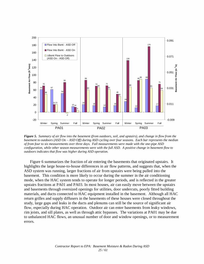
Figure 5. Summary of air flow into the basement (from outdoors, soil, and upstairs), and change in flow from the basement to outdoors (ASD On – ASD Off) during ASD cycling over four seasons. Each bar represents the median of from four to six measurements over three days. Fall measurements were made with the one-pipe ASD configuration, while other season measurements were with the full ASD. A positive change in basement flow to outdoors indicates that flow was higher during ASD operation.
Figure 6 summarizes the fraction of air entering the basements that originated upstairs. It
highlights the large house-to-house differences in air flow patterns, and suggests that, when the ASD system was running, larger fractions of air from upstairs were being pulled into the basement. This condition is more likely to occur during the summer in the air conditioning mode, when the HAC system tends to operate for longer periods, and is reflected in the greater upstairs fractions at PA01 and PA03. In most houses, air can easily move between the upstairs and basements through oversized openings for utilities, door undercuts, poorly fitted building materials, and ducts connected to HAC equipment installed in the basement. Although all HAC return grilles and supply diffusers in the basements of these houses were closed throughout the study, large gaps and leaks in the ducts and plenums can still be the source of significant air flow, especially during HAC operation. Outdoor air can enter basements from leaky windows, rim joists, and sill plates, as well as through attic bypasses. The variations at PA01 may be due to unbalanced HAC flows, an unusual number of door and window openings, or to measurement errors.

Contractor Report to EPA: Basement Moisture & Radon During ASD 26 / 61
35
80
15
24 24
47
24
37
34
87
48
45
3432
55
50 48
39
69
84
79
89
67
85
0
10
20
30
40
50
60
70
80
90
100
Winter Spring Summer Fall Winter Spring Summer Fall Winter Spring Summer
Fra
ctio
n o
f F
low
In
to B
asem
ent
fro
m U
psta
irs
(%)
Upstairs Fraction - ASD Off
Upstairs Fraction - ASD On
PA01 PA02 PA03
Figure 6. Summary of the fraction of air flow into the basement that originated from upstairs. The balance is assumed to be from outdoors or the soil. As in Figure 5, each bar represents the median of multiple measurements during each period.
Outdoor air ventilation rates (infiltration) for the basements and upstairs zones are
summarized in Table 3 according to ASD On and Off periods. Data from the four to six test periods for each of the four seasons have been aggregated. Because of the large range in measured ventilation rates for some of the houses, the median infiltration is presented along with the arithmetic mean and standard deviation. For PA01 and PA03, ventilation rates in the basements tend to be much lower than for the upstairs, with basement ventilation in PA03 being almost a factor of 5 to 8 lower. At PA02 and PA03, ASD operation caused large increases (60% to over 200%) in the ventilation rates when the ASD was on for both the basement and upstairs.
The median ventilation rate for the basements of these houses with ASD off was just adequate to meet the ventilation required by ASHRAE Standard 62.2 (2007). With ASD on, the basement ventilation increased to well over the requirement for PA02 and PA03, but was unchanged for PA01. The median baseline (ASD off) ventilation rate for the upstairs of PA01 and PA03 exceeded the ASHRAE requirement, while even with the system operating at PA02, the median upstairs ventilation was below the minimum.
Both of these block wall houses also had the largest fraction of basement air in the ASD exhaust (Table 4, below), and the highest ASD exhaust flow rates. The complete ventilation and interzonal flow data are found in Appendix F.

Contractor Report to EPA: Basement Moisture & Radon During ASD 27 / 61
Table 3. Summary of Outdoor Air Ventilation in the Basement and Upstairs
Outdoor to Basement Infiltration
(ach) Outdoor to Upstairs Infiltration
(ach)
House ID
ASD Status Mean/Std.Dev
Mean ∆Off/On1
(%) Median
Mean ∆Off/On1
(%) Mean/Std.Dev
Mean ∆Off/On1
(%) Median
Mean ∆Off/On1
(%)
PA01 – 4 Seasons
Off 0.11 / 0.062 -- 0.07 -- 0.47 / 0.474 -- 0.20 --
On 0.10 / 0.065 -10 0.07 -11 0.22 / 0.092 -12 0.28 18
ASHRAE2 0.07 0.16
PA02 – 4 Seasons Off 0.05 / 0.048 -- 0.07 -- 0.07 / 0.019 -- 0.06 --
On 0.16 / 0.032 280 0.18 150 0.22 / 0.084 200 0.18 220
ASHRAE 0.07 0.23
PA03 – 4 Seasons Off 0.09 / 0.056 -- 0.08 -- 0.82 / 0.122 -- 0.69 --
On 0.22 / 0.125 180 0.21 110 1.11 / 0.100 39 1.08 66
ASHRAE 0.07 0.20
All House Totals – 4 Seasons Off 0.08 / 0.056 -- 0.07 -- 0.45 / 0.408 -- 0.20 --
On 0.16 / 0.093 150 0.16 97 0.52 / 0.445 76 0.28 67 1 The arithmetic mean and median of the individual seasonal changes (∆ASD Off/ASD On) in the ventilation rates was calculated, and may be different than the change in the summarized 4-season ventilation rate. 2 ASHRAE ventilation required for each house is based on floor area and number of bedrooms (ASHRAE Std. 62.2, 2007)
3.5.1 Basement Air in ASD Exhaust. The tracer gas measurements were also used to
determine the make-up or source of ASD discharge air. Table 4 shows the percentage of ASD discharge air that originated in the basement, based on tracer found in samples of discharge and basement air taken within a few minutes of each other. These measurements were performed during operation of the modified ASD systems (single pipe through the slab). The basement air can enter the ASD system through multiple pathways, such as cracks and holes in the foundation walls and floor (discussed in the conceptual model).
Table 4. Basement Air in ASD Exhaust
House ID Fraction of Air in ASD Exhaust
Originating in the Basement (%)
PA01 46
PA02 72
PA03 72
House PA01, with poured walls, sealed sump, sealed wall/floor joint, sealed utility
penetrations and limited visible cracks in the walls or slab, apparently had the least leakage between the basement interior and the region around the foundation depressurized by the ASD systems. Even so, the tracer gas measurement indicates that approximately 46% of the ASD discharge air came from the basement. In PA02 and PA03, approximately 72% of the discharge air is from the basement. Block walls under direct or indirect depressurization would seem a likely pathway for additional loss of basement air to the ASD system in those two structures. These data are consistent with other studies (of seven houses) that reported between 40 and 90% of the air in ASD exhaust originated in the basement (Turk et al 1991).

Contractor Report to EPA: Basement Moisture & Radon During ASD 28 / 61
3.6 Indoor Radon Concentrations
Active soil depressurization systems for radon control are the workhorse technique for reliably reducing indoor radon levels. A plot of typical changes in basement air radon concentrations as the ASD system was cycled on and off at PA02 is displayed in Figure 7, which shows large reductions regardless of system configuration. As seen in Figure 8, all of the systems installed in this project were very successful at reducing basement concentrations well below the US EPA’s mitigation action level of 4 pCi/L (148 Bq/m3) – even approaching levels in the outdoor air. The modified ASD configurations also demonstrate robust reductions.
0.0
4.0
8.0
12.0
16.0
20.0
24.0
28.0
32.0
36.0
10/15/05 11/24/05 1/3/06 2/12/06 3/24/06 5/3/06 6/12/06 7/22/06 8/31/06 10/10/06 11/19/06 12/29/06
Rad
on
Co
nce
ntr
atio
n (
pC
i/L
)
0.00
5.00
10.00
15.00
20.00
25.00ASD Full On/Off
ASD Single-Pipe On/Off
Basement Rn
Figure 7. Radon levels in the basement air of PA03 during ASD cycling, for periods of full ASD(multiple pipe) and single-pipe operation.

Contractor Report to EPA: Basement Moisture & Radon During ASD 29 / 61
59.3
16.1
13.2
51.9
0.6 0.30.4 0.9 0.51.7 0.7
0
4
8
12
16
20
24
28
32
36
40
44
48
52
56
60
64A
vera
ge
Bas
men
t R
ado
n (
pC
i/L
)
EPA's RadonMitigation Action Level
4 pCi/L
PA01 PA02 PA03
(1809) (1119) (1969) (2468) (11150) (4359) (3764) (1199) (4508) (2946) (1264)
A = Off, Baseline
B = Seal Wall/Floor Joint
C = Full ASD, All Pipes Open
D = Single Subslab ASD Pipe
A A+B C C+B D+B A C D A C D
< Hrs Monitored
Figure 8. Average basement air radon concentrations during ASD cycling (≥7-day cycle periods) for September 2005 through January 2007. Various mitigation configurations are identified by the letter codes, and the accumulated hours of monitoring for each configuration are shown below the data bars.
As summarized in Tables 5 - 7, radon concentrations, with ASD off, on the 1st floor of these
houses were approximately 25 to 50% of the basement concentrations, which is typical for houses with HAC systems. Radon concentrations below the slab floor and on the exterior side of the walls had large reductions during ASD operation, presumably because radon was being diluted with ventilation air from outdoors or the basement (through cracks and openings). The smallest reduction in wall radon levels occurred at PA01, the house with poured concrete walls. Single ASD pipe operation tended to cause slightly smaller reductions in radon levels at most locations. These results also indicate that the primary source of radon for these houses was pressure-driven entry from the soil.
Other than in house PA02, additional depressurization of the basement is not measurable with ASD systems on. At PA02, the house with the smallest air leakage area, it is likely that the ASD systems are increasing the basement depressurization with respect to upstairs and to outdoors. The additional depressurization is probably the result of basement air being extracted by the ASD system through cracks and openings in the basement walls and floor (see Figure 3).
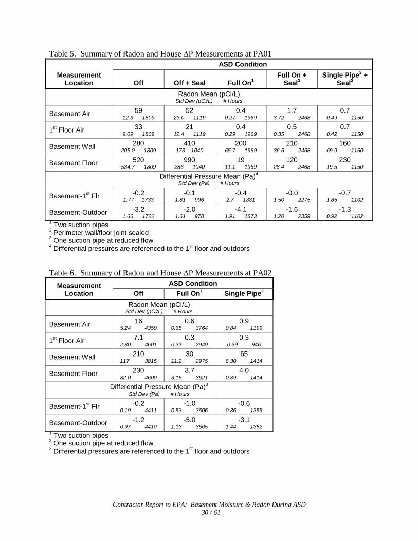
Contractor Report to EPA: Basement Moisture & Radon During ASD 30 / 61
Table 5. Summary of Radon and House ∆P Measurements at PA01
Measurement Location
ASD Condition
Off Off + Seal Full On1 Full On +
Seal2 Single Pipe3 +
Seal2
Radon Mean (pCi/L) Std Dev (pCi/L) # Hours
Basement Air 59 12.3 1809
52 23.0 1119
0.4 0.27 1969
1.7 3.72 2468
0.7 0.49 1150
1st Floor Air 33 9.09 1809
21 12.4 1119
0.4 0.29 1969
0.5 0.35 2468
0.7 0.42 1150
Basement Wall 280 205.0 1809
410 173 1040
200 65.7 1969
210 36.6 2468
160 69.9 1150
Basement Floor 520 534.7 1809
990 286 1040
19 11.1 1969
120 28.4 2468
230 19.5 1150
Differential Pressure Mean (Pa)4 Std Dev (Pa) # Hours
Basement-1st Flr -0.2 1.77 1733
-0.1 1.81 996
-0.4 2.7 1881
-0.0 1.50 2275
-0.7 1.85 1102
Basement-Outdoor -3.2 1.66 1722
-2.0 1.61 978
-4.1 1.91 1873
-1.6 1.20 2359
-1.3 0.92 1102
1 Two suction pipes 2 Perimeter wall/floor joint sealed 3 One suction pipe at reduced flow 4 Differential pressures are referenced to the 1st floor and outdoors Table 6. Summary of Radon and House ∆P Measurements at PA02
Measurement Location
ASD Condition Off Full On1 Single Pipe2
Radon Mean (pCi/L) Std Dev (pCi/L) # Hours
Basement Air 16 5.24 4359
0.6 0.35 3764
0.9 0.84 1199
1st Floor Air 7.1 2.80 4601
0.3 0.33 2949
0.3 0.39 946
Basement Wall 210 117 3815
30 11.2 2975
65 8.30 1414
Basement Floor 230 82.0 4600
3.7 3.15 3621
4.0 0.89 1414
Differential Pressure Mean (Pa)3 Std Dev (Pa) # Hours
Basement-1st Flr -0.2 0.19 4411
-1.0 0.53 3606
-0.6 0.36 1355
Basement-Outdoor -1.2 0.97 4410
-5.0 1.13 3605
-3.1 1.44 1352
1 Two suction pipes 2 One suction pipe at reduced flow 3 Differential pressures are referenced to the 1st floor and outdoors

Contractor Report to EPA: Basement Moisture & Radon During ASD 31 / 61
Table 7. Summary of Radon and House ∆P Measurements at PA03
Measurement Location
ASD Condition Off Dehumid Full On1 Single Pipe2
Radon Mean (pCi/L) Std Dev (pCi/L) # Hours
Basement Air 13 5.75 4508
11 4.42 909
0.3 0.19 2946
0.5 0.27 1264
1st Floor Air 4.4 2.09 4514
5.1 1.91 911
0.2 0.17 2947
0.3 0.22 1264
Basement Wall 130 295 4514
87 32.3 911
33 3.47 2947
28 5.78 1264
Basement Floor 650 388 4514
620 232 911
35 13.4 2947
29 2.96 1264
Differential Pressure Mean (Pa)3 Std Dev (Pa) # Hours
Basement-1st Flr -0.1 0.32 4135
-0.8 0.83 872
-0.8 0.72 2820
-0.5 0.67 1211
Basement-Outdoor -1.9 1.18 4132
-1.5 0.88 872
-3.2 1.61 2820
-2.1 0.96 1210
1 Three suction pipes – two into the block wall, and one below the slab 2 One sub-slab suction pipe at reduced flow 3 Differential pressures are referenced to the 1st floor and outdoors 3.7 Basement Moisture
Time series plots of the basement air RH at PA01 – PA03 and outdoor air humidity ratio are presented in Figures 9 - 11. Because changes in outdoor air temperature add to other large and rapid variations in outdoor air RH, humidity ratios were computed to negate some of the temperature effects. While the plots cover a 10- to 15-month period when the ASD system was being cycled on and off, the dominant trend in the basement air RH tracks with the outdoor air moisture levels. Closer inspection of the plots suggests that the basement RH does change in response to many of the periods of ASD operation, but that this response is superimposed on the larger and longer seasonal changes in outdoor air moisture. These data also hint that moisture responses are more muted and less predictable in the summer months.

Contractor Report to EPA: Basement Moisture & Radon During ASD 32 / 61
0
10
20
30
40
50
60
70
80
9/12
/05
10/1
2/05
11/1
1/05
12/1
1/05
1/10
/06
2/9/0
6
3/11
/06
4/10
/06
5/10
/06
6/9/0
6
7/9/0
6
8/8/0
6
9/7/0
6
10/7/
06
Bas
emen
t Air
RH
(%)
0
5
10
15
20
25
Out
door
Air
Hum
idity
Rat
io (g
/kg)
Basement RH
Out Hum Ratio
ASD Full (On/Off)
ASD Single-Pipe (On/Off)
Figure 9. Moisture levels in basement air (RH) and outdoor air (humidity ratio, W) over a 13-month period at PA01, during ASD system cycling. ASD ‘on’ periods are indicated by the rectangular bars near the top of the plot.

Contractor Report to EPA: Basement Moisture & Radon During ASD 33 / 61
0
10
20
30
40
50
60
70
80
10/1
5/05
11/1
4/05
12/1
4/05
1/13
/06
2/12
/06
3/14
/06
4/13
/06
5/13
/06
6/12
/06
7/12
/06
8/11
/06
9/10
/06
10/1
0/06
11/9/
06
12/9/
06
1/8/0
7
Bas
emen
t A
ir R
H (
%)
0
5
10
15
20
25
Ou
tdo
or
Air
Hu
mid
ity
Rat
io (
g/k
g)
Basement RH
Out Hum Ratio
ASD Full (On/Off)
ASD Single-Pipe (On/Off)
Figure 10. Moisture levels in basement air (RH) and outdoor air (humidity ratio, W) over a 15-month period at PA02, during ASD system cycling.

Contractor Report to EPA: Basement Moisture & Radon During ASD 34 / 61
0
10
20
30
40
50
60
70
80
10/15
/05
11/14
/05
12/14
/05
1/13/
06
2/12/
06
3/14/
06
4/13/
06
5/13/
06
6/12/
06
7/12/
06
8/11/
06
9/10/
06
10/10
/06
11/9
/06
12/9
/06
1/8/0
7
Bas
emen
t A
ir R
H (
%)
0
5
10
15
20
25
Ou
tdo
or
Air
Hu
mid
ity
Rat
io (
g/k
g)
Basement RH
Out Hum Ratio
ASD Full (On/Off)
ASD Single-Pipe (On/Off)
Figure 11. Moisture levels in basement air (RH) and outdoor air (humidity ratio, W) over a 15-month period at PA03, during ASD system cycling.
The equilibrium RH data from one sensor cluster in the walls at each of the three houses are
shown for the same time periods in Figures 12 - 14. These data are representative of that from other wall locations, with poured wall locations (PA01) exhibiting behavior more like that of the slab floors (Figures 15 – 17). In contrast to the basement air RH, the data for many of the sensors embedded within the block cores (‘Core’) and within approximately two cm of the interior surface of the block (‘Interior’) display large and dramatic changes as the ASD is cycled (block wall houses PA02 and PA03, Figures 13 and 14). The sensors mounted on the exterior surface of the walls (‘Thru Wall’) typically do not have an observable response to the ASD operation, and after remaining in saturated conditions, many eventually failed. However, the plot of the Thru-wall moisture at W9 in PA03 (Figure 14) suggests that it too is responding as expected to ASD operation. It is not clear that the Interior and Core locations of the block walls (PA02 and PA03) reached steady state conditions even after two weeks of operation. Additional analysis of these responses is required. Although the ASD system causes reductions of almost 30% RH when outdoor moisture levels are low, the response is dampened somewhat during the more humid summer months. When the ASD system at house PA03 was operated with only the sub-slab pipe (”Single pipe”), reductions in wall moisture are greatly diminished (Figure 14). Clearly, the block wall ventilation component of the ASD system had a large impact on wall moisture at this house.

Contractor Report to EPA: Basement Moisture & Radon During ASD 35 / 61
40
50
60
70
80
90
100
9/12
/05
10/1
2/05
11/1
1/05
12/1
1/05
1/10
/06
2/9/0
6
3/11
/06
4/10
/06
5/10
/06
6/9/0
6
7/9/0
6
8/8/0
6
9/7/0
6
10/7
/06
Po
ure
d W
all I
nte
rio
r &
Mid
-dep
th E
qui
libri
um R
H (%
)
0
5
10
15
20
25
30
35
40
Th
ru-w
all R
H (
%)
Interior
Mid-depth
ASD Full (On/Off)
ASD Single-Pipe (On/Off)
Figure 12. Plot of equilibrium RH at two depths in poured wall location W26 at house PA01 while ASD systems were cycled. ‘Interior’ refers to the sensor embedded in the poured wall approximately 2 cm from the basement-facing surface. The ‘Thru’ wall (exterior) sensor failed due to prolonged exposure to saturated conditions, as did other RH sensors in similar conditions.

Contractor Report to EPA: Basement Moisture & Radon During ASD 36 / 61
0
20
40
60
80
100
120
10/1
5/05
11/1
4/05
12/1
4/05
1/13/
06
2/12/
06
3/14/
06
4/13/
06
5/13/
06
6/12/
06
7/12/
06
8/11/
06
9/10/
06
10/1
0/06
11/9/
06
12/9/
06
1/8/0
7
Blo
ck W
all
Eq
uil
ibri
um
RH
(%
)
Interior
Core
Thru Wall
ASD Full (On/Off)
ASD Single-Pipe (On/Off)
Figure 13. Plot of equilibrium RH at three depths in block wall location W27 at house PA02 while ASD systems were cycled. ‘Interior’ refers to the sensor embedded in the block web approximately 2 cm from the basement-facing surface.

Contractor Report to EPA: Basement Moisture & Radon During ASD 37 / 61
0
20
40
60
80
100
120
10/1
5/05
11/1
4/05
12/1
4/05
1/13
/06
2/12
/06
3/14
/06
4/13
/06
5/13
/06
6/12
/06
7/12
/06
8/11
/06
9/10
/06
10/1
0/06
11/9/
06
12/9/
06
1/8/0
7
Blo
ck W
all I
nte
rio
r &
Co
re E
qu
ilib
riu
m R
H (
%)
80
82
84
86
88
90
92
94
96
98
100
Blo
ck W
all T
hru
-wal
l Eq
uili
bri
um
RH
(%
)
Interior
Core
Thru Wall
ASD Full (On/Off)
ASD Single-Pipe (On/Off)
Figure 14. Plot of equilibrium RH at three depths in block wall location W9 at house PA03 while ASD systems were cycled. Block wall ventilation pipes were disabled during ASD single-pipe cycling.
The plot for the poured walls at house PA01 (Figure 12) and the slab floors at all houses
(Figures 15 – 17) tend to demonstrate much smaller responses to changes in ASD operation. The trend for most wall and floor locations is for the equilibrium RH to increase with depth into the wall or floor material. While the shallower test locations (walls – “Interior”, floors – “Top”) are often more responsive to ASD cycling and track with changes in basement air moisture (Figure 12), there are exceptions. For example, although some block wall cores have high baseline (ASD off) moisture levels, they show larger reductions than the “Interior” locations when the ASD is on (Figures 13 and 14). And several “Thru-slab” floor locations also have large reductions in equilibrium RH when the ASD is running (for example, D1 at PA01 -- Figure 15). These results indicate that the ASD systems are causing comparatively large changes in flow of air with low water vapor pressure, in the gas-permeable sub-slab aggregate.

Contractor Report to EPA: Basement Moisture & Radon During ASD 38 / 61
40
45
50
55
60
65
70
75
80
85
90
9/12
/05
10/12
/05
11/11
/05
12/11
/05
1/10
/06
2/9/0
6
3/11
/06
4/10
/06
5/10
/06
6/9/0
6
7/9/0
6
8/8/0
6
9/7/0
6
10/7
/06
Sla
b F
loo
r E
qu
ilib
riu
m R
H (
%)
0
10
20
Th
ru-w
all R
H (
%)
Top
Mid-depth
Thru Slab
ASD Full (On/Off)
ASD Single-Pipe (On/Off)
Figure 15. Plot of equilibrium RH at three depths for slab floor location D1 at house PA01 while ASD systems were cycled. ‘Top’ refers to the sensor embedded in the slab approximately 2 cm from the top surface. Thru-slab sensors were generally in the aggregate below the concrete slab.

Contractor Report to EPA: Basement Moisture & Radon During ASD 39 / 61
60
70
80
90
100
110
120
10/15
/05
11/14
/05
12/14
/05
1/13/
06
2/12/
06
3/14/
06
4/13/
06
5/13/
06
6/12/
06
7/12/
06
8/11/
06
9/10/
06
10/10
/06
11/9
/06
12/9
/06
1/8/0
7
Sla
b F
loo
r In
teri
or
& C
ore
Eq
uili
bri
um
RH
(%
)
40
50
60
70
80
90
100
110
Sla
b F
loo
r T
hru
-sla
b E
qu
ilib
riu
m R
H (
%)
Top
Mid-depth
Thru Slab
ASD Full (On/Off)
ASD Single-Pipe (On/Off)
Figure 16. Plot of equilibrium RH at three depths for slab floor location C4 at house PA02 while ASD systems were cycled. ‘Top’ refers to the sensor embedded in the slab approximately 2 cm from the top surface. Thru-slab sensors were generally in the aggregate below the concrete slab.

Contractor Report to EPA: Basement Moisture & Radon During ASD 40 / 61
60
65
70
75
80
85
90
95
100
10/1
5/05
11/1
4/05
12/1
4/05
1/13
/06
2/12
/06
3/14
/06
4/13
/06
5/13
/06
6/12
/06
7/12
/06
8/11
/06
9/10
/06
10/1
0/06
11/9
/06
12/9
/06
1/8/0
7
Flo
or
To
p &
Mid
Eq
uili
bri
um
RH
(%
)
0
20
40
60
80
100
120
Flo
or
Th
ru-s
lab
Eq
uili
bri
um
RH
(%
)
Top
Mid-depth
Thru Slab
ASD Full (On/Off)
ASD Single-Pipe (On/Off)
Figure 17. Plot of equilibrium RH at three depths for slab floor location D3.5 at house PA03 while ASD systems were cycled. As with the Thru-wall sensors, many of the Thru-slab sensors also failed.
To show the comparative changes in moisture levels in the air, wall, and floor during ASD cycling in house PA02, data from three figures (10, 13, and 16) are combined in Figure 18. Moisture changes in the air and foundation materials track together, but with different response characteristics.

Contractor Report to EPA: Basement Moisture & Radon During ASD 41 / 61
0
10
20
30
40
50
60
70
80
90
100
10/1
5/05
11/1
4/05
12/1
4/05
1/13
/06
2/12
/06
3/14
/06
4/13
/06
5/13
/06
6/12
/06
7/12
/06
8/11
/06
9/10
/06
10/1
0/06
11/9
/06
12/9
/06
1/8/0
7
Bas
emen
t A
ir, W
all &
Flo
or
RH
(%
)
0
5
10
15
20
25
Ou
tdo
or
Air
Hu
mid
ity
Rat
io (
g/k
g)
Basement Air
Wall Interior (W27)
Slab Top (C4)
ASD Full (On/Off)
ASD Single Pipe (On/Off)
Figure 18. Tracking moisture levels in the basement air along with one near-surface location for the wall and slab floor at PA02.
The aggregated mean RH for most of the air, wall, and floor locations are compared for the
ASD on and off periods during various configurations of the mitigation systems in Figures 19 – 21. The data are from Day 7 – 14 from the 14-day, and longer, cycle periods. This one week lag was used so that moisture conditions had more time to equilibrate before data were averaged. However, the data indicate that, for many of the foundation materials, a much longer ASD on or off period will be required before quasi-equilibrium is reached. Consequently, these data likely do not represent steady state moisture levels for extended ASD operation. For walls and floors, results from all sensors at all clusters were grouped. The data are also grouped by summer and non-summer conditions. The beginning and end of summer was arbitrarily defined for the purposes of this analysis as occurring when the daily average outdoor air dew point changed to being above (summer) or below (non-summer) 60°F (15.6°C) for five consecutive days. For the study site, this occurred in late-May/early June and September. Many of the differences (both increases and decreases) between mean RH for On and Off periods are statistically significant (p<0.05, value shown in figures), yet the magnitude of the differences are so slight as to indicate there was little practical change in moisture levels. Comparison of changes in indoor moisture levels with those in the outdoor air will be reported separately after analyses, and possible development of a statistical model, investigating the relationship of indoor moisture to many other factors.

Contractor Report to EPA: Basement Moisture & Radon During ASD 42 / 61
The data for PA01 (with poured walls) show the trend of increasing moisture the deeper into the wall or floor, and the closer to the surrounding soil (Figure 19). The soil side of the slab floors appears to benefit from the presence of the gravel layer, acting as a capillary break. Full ASD system operation (ASD On/ASD Off) produced a modest reduction of approximately 4% RH in basement air and Thru-slab locations (before crack sealing), possibly due to the system’s direct impact on air flow in those areas. Moisture changes in the remaining wall and slab locations are usually less than 1% RH. It is interesting to observe that after sealing of the wall/floor joint, average moisture levels at some locations increased slightly during baseline and ASD on periods. Sealing the crack may have reduced the amount or pattern of air flowing in and around these materials. Cycling data for the reduced, single-pipe and summer operation at this house are very limited and not presented here.
44.4
53.6
84.0
99.8
62.1 66
.0
85.2
40.
7
54.1
83.9
99.3
62.3 66
.2
81.
0
45.9
56.
4
83.8
99.4
63.5 66
.9
83.8
45.6
56.
4
83.5
99.3
63.8 66
.9
77.8
0
10
20
30
40
50
60
70
80
90
100
Interior Middle Thru Top Middle Thru
Mea
n R
elat
ive
Hu
mid
ity (%
)
ASD OffASD Full OnASD Off - Crack SealASD Full On - Crack Seal
Poured Walls Slab FloorBasement Air
p<.0001
p=0.2994
p<.0001
p=0.6901
p=0.0063
p<.0001
p<.0001
p<.0001
p=0.2336
p=0.3214
p=0.0274
p=0.7467
p<.0001
p<.0001
Figure 19. Summary of arithmetic mean RH for second 7 days of 14-day, or longer, cycling periods at PA01. In addition to RH in basement air, all wall and slab floor cluster locations (Interior, Top, Middle, Thru) with legitimate sensor values were aggregated. The wall/floor joint was sealed in March 2006, and is separately presented in the data as ‘Crack Seal’. The statistical significance of the difference (p, two-tail) between various ‘off’ and ‘on’ segments is indicated in the boxes below. These non-summer data are from September 2005 through May 2006.
Sufficient data were available at PA02 to present results from single-pipe ASD operation (ASD Reduced), and for the summer months (Figure 20). Insufficient data are available from the Thru wall and Thru slab locations due to sensor failures. The mean RH in the basement air, block surfaces within 2 cm of the basement interior, and the block cores experienced large and

Contractor Report to EPA: Basement Moisture & Radon During ASD 43 / 61
significant reductions during non-summer operation of both the full and single-pipe ASD system. Mean humidity reductions in basement air during non-summer operation were more than 7% RH. Moisture reductions in block Interior and Core during full operation averaged over 18% and 23% RH, respectively. For the single-pipe configuration, reductions in the wall were smaller – over 15% and 13%. There are similar, but attenuated, responses at the slab floor locations. Moisture in the basement air for the reduced, single-pipe configuration was reduced from 56% RH to 49% RH. A moisture level favorable to dust mites and some molds is commonly assumed to be 50% RH, or greater, in the air. The single-pipe configuration (PA02 and PA03) was operated for 5½ months, from August 2006 into January 2007, so that data on the four-season performance of this configuration is not available.
Changes in the mean RH during the summer period were smaller and more equivocal, but most apparent at the two depths of the walls. The basement air RH of 62%, with the ASD system on, would be suitable for the growth of some microbiological organisms.
41.0
60.4
80.
6 82.5
89.8
33.8
41.6
57.5
80.
2
88.
9
56.4
73.9
87.2
85.6
91.3
48.7
58.3
74.1
83.2
90.3
60.9
74.1
88.
3
86.7
91.0
61.
8
68.1
83.9 87
.1 90.7
0
10
20
30
40
50
60
70
80
90
100
Interior Core Top Middle
Mea
n R
elat
ive
Hu
mid
ity (%
)
ASD OffASD Full OnASD Single-Pipe OffASD Single-Pipe OnSummer -- ASD OffSummer -- ASD Full On
p<.0001
Block Walls Slab Floor
p<.0001
p=0.1888
p<.0001
p<.0001
p<.0001
p<.0001
p<.0001
p<.0001
p<.0001
p<.0001
p=0.3333
p<.0001
p<.0001
p=0.3958
Basement Air
Figure 20. Arithmetic mean RH for second 7 days of 14-day, or longer, cycling periods at PA02. These data are for December 2005 through January 2007, and include summer periods, and periods when the ASD operation was reduced to a single pipe.
At PA03, mean RH changes mimic those for PA02, but with an even larger change in the cores of the block walls during full system, non-summer, operation (30% RH). This enhanced response in the block cores is due to the additional ventilation applied by the ASD pipes installed directly into the wall blocks. The average drop in basement air RH was 10%, and 18% for block

Contractor Report to EPA: Basement Moisture & Radon During ASD 44 / 61
Interior during full system operation. While the single, sub-slab pipe was being used, the reductions were smaller: 8% RH in the basement air, 3% RH for the block Interior, and 6% in the block Core locations. Moisture reductions at the slab floor and through-block locations were generally less than 2%. The decrease in moisture levels during the summer was much less: 1% RH in basement air RH, 8% in block Interior, and 14% in the block Cores.
49.1
70.0
83.0
95.
7
73.
5
89.7
98.7
39.1
51.
7
52.3
95.2
70.9
88.4
96.
5
60.5
88.4 92
.0
97.2
77.2
89.1
52.9
85.
1
85.9
97.6
76.4
89.4
70.3
79.6
88.5
94.7
81.7
91.2
98.1
69.3 71
.8 74.7
93.7
79.1
89.8
95.
7
ND
ND
0
10
20
30
40
50
60
70
80
90
100
110
Interior Core Thru Top Middle Thru
Mea
n R
elat
ive
Hu
mid
ity (%
)
ASD OffASD Full OnASD Single-Pipe OffASD Single-Pipe OnSummer -- ASD OffSummer -- ASD Full On
p<.0001
Block Walls Slab Floor
p<.0001
p=0.1890
Basement Air
p<.0001
p=<.0001
p<.0001
p<.0001
p<.0001
p<.0001
p<.0001
p<.0001
p<.0001
p<.0001
p<.0001
p<.0001
p<.0001
p=0.0024
p<.0001
p<.0001
p<.0001
Figure 21. Arithmetic mean RH for second 7 days of 14-day, or longer, cycling periods at PA03. These data are for December 2005 through January 2007, and include summer periods, and periods when the ASD operation was reduced to a single sub-slab pipe. When data were not available, it is indicated by ND.
A more revealing analysis of the change caused by the ASD operation is to examine the rate of change in moisture (RH). Performing autoregression analysis (with lag of 2) for the first seven days of seven day and longer cycle periods yields results similar to those shown in Figure 22 for basement air RH at PA02. The first seven days were chosen as being expected to demonstrate the largest and measurable change in moisture – if any had occurred. The regression lines clearly show the trends as the ASD operating condition is changed. The slope of the regression lines for each phase of the ASD cycle were then aggregated and used as a surrogate for the rate of change in moisture in the air and within the foundation materials. Since the moisture rate of change slowly diminishes over time, a linear regression is not a true representation of long-term moisture changes. Therefore, the slopes should not be used to extrapolate beyond the seven-day period of analysis.
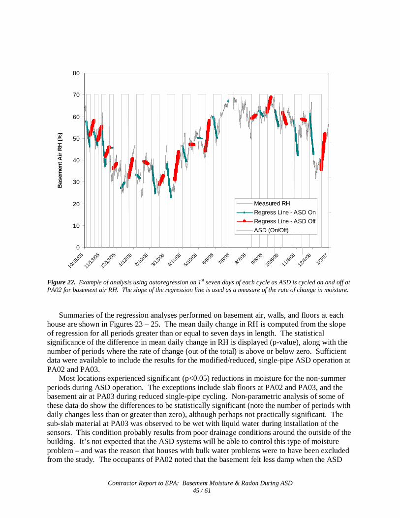
Contractor Report to EPA: Basement Moisture & Radon During ASD 45 / 61
0
10
20
30
40
50
60
70
80
10/15
/05
11/13
/05
12/13
/05
1/12
/06
2/10
/06
3/12
/06
4/11
/06
5/10
/06
6/9/
06
7/9/
06
8/7/
06
9/6/
06
10/6/
06
11/4/
06
12/4/
06
1/3/
07
Bas
emen
t Air
RH
(%
)
0
5
10
15
20
25
Out
doo
r A
ir H
umid
ity
Rat
io (g
/kg)
Measured RH
Regress Line - ASD On
Regress Line - ASD Off
ASD (On/Off)
Figure 22. Example of analysis using autoregression on 1st seven days of each cycle as ASD is cycled on and off at PA02 for basement air RH. The slope of the regression line is used as a measure of the rate of change in moisture.
Summaries of the regression analyses performed on basement air, walls, and floors at each house are shown in Figures 23 – 25. The mean daily change in RH is computed from the slope of regression for all periods greater than or equal to seven days in length. The statistical significance of the difference in mean daily change in RH is displayed (p-value), along with the number of periods where the rate of change (out of the total) is above or below zero. Sufficient data were available to include the results for the modified/reduced, single-pipe ASD operation at PA02 and PA03.
Most locations experienced significant (p<0.05) reductions in moisture for the non-summer periods during ASD operation. The exceptions include slab floors at PA02 and PA03, and the basement air at PA03 during reduced single-pipe cycling. Non-parametric analysis of some of these data do show the differences to be statistically significant (note the number of periods with daily changes less than or greater than zero), although perhaps not practically significant. The sub-slab material at PA03 was observed to be wet with liquid water during installation of the sensors. This condition probably results from poor drainage conditions around the outside of the building. It’s not expected that the ASD systems will be able to control this type of moisture problem – and was the reason that houses with bulk water problems were to have been excluded from the study. The occupants of PA02 noted that the basement felt less damp when the ASD

Contractor Report to EPA: Basement Moisture & Radon During ASD 46 / 61
was running. Block walls tended to have the greatest reductions, possibly because the relatively open and porous nature of the blocks permitted greater air flow in and around the walls. The poured walls at PA01 exhibit a response like that of the slab floors in all houses, probably because of their similar dense construction and slower response to changing moisture conditions. Longer ASD on periods may result in more pronounced changes in these materials, as is suggested by preliminary data from PA01 where the ASD system was operated almost continuously after May 2006.
As seen in Figures 9 – 12, basement moisture levels tend to increase during the summer – however, ASD operation still may have a modest impact on the mean daily change in RH at PA01 and PA02. Although some of these reductions are not considered significant according to classical statistical tests (assuming normal distribution), non-parametric analyses indicate the differences may be significant. If additional basement ventilation with upstairs and outdoor air accounts for the drying observed during the non-summer, it may also cause a countervailing effect during the summer. Humid air drawn into the basement from outdoors in the summer could add significant moisture to the basement, as Figure 25 may show for PA03.
In contrast with the data for mean RH (Figures 20 and 21), the mean daily change in RH during non-summer operation of the ASD systems with reduced, single-pipe configurations for PA02 and PA03 is similar to that for full system operation. During the summer, these ‘typical’ ASD configurations appear to be more vulnerable to the high moisture loads in the outdoor air – with their moisture-reducing performance becoming more marginal.
A similar trend analysis of moisture levels was performed on the first 14 days of each cycle period for the three houses. The data, included in Appendix H, tend to exhibit smaller changes during both ASD Off and ASD On periods. This dampened response for the longer analysis times is likely due to the gradually decreasing change in moisture as the house and its materials slowly approach a new moisture equilibrium. However, the pattern of moisture reductions during ASD operation is still apparent. The data from the 14-day analysis at PA01 supports the observation that sealing of the perimeter wall/floor joint in the basement tended to diminish the moisture reductions during ASD operation.

Contractor Report to EPA: Basement Moisture & Radon During ASD 47 / 61
0.60
0.17 0.17
-0.24
-0.15
-0.27
0.29
0.05
0.14
-0.25
0.00
-0.10
-0.6
-0.4
-0.2
0.0
0.2
0.4
0.6
0.8
Basement Air Poured Walls Slab Floor
Mea
n D
aily
Ch
ang
e in
Rel
ativ
e H
um
idity
(%)
ASD OffASD Full On
Summer -- ASD Off
Summer -- ASD Full On
p=0.01339/11>0 6/11<0
p<.000168/88>0 71/86<0
p=0.032912/16>0 24/32<0
p=0.41352/2>0 3/4<0
p=0.011553/75>0 54/73<0
p=0.53488/14>0 21/28<0
Figure 23. Summary of arithmetic mean daily change for first 7 days of period in basement moisture levels in the air, walls, and slab floor at house PA01 during ASD cycling. Periods with full ASD + crack sealing are grouped with ASD Full On. The statistical significance of the difference (p, two-tail) between ‘off’ and ‘on’ is indicated in the box below, along with the number of ‘off’ and ‘on’ cycles (out of total) with a rate of change greater than and less than 0, respectively. For walls and floors, data from a number of different locations are aggregated, as reflected in the total number of cycles. Data include summer and non-summer periods from September 2005 through October 2006.

Contractor Report to EPA: Basement Moisture & Radon During ASD 48 / 61
0.87
2.22
0.13
-1.24
-2.44
-0.23
-2.00
-2.47
-0.21
0.86
1.18
0.27
-1.24
-1.76
-0.13-0.37
-0.93
-0.11
-4.0
-3.0
-2.0
-1.0
0.0
1.0
2.0
3.0
Basement Air Block Walls Slab Floor
Mea
n D
aily
Ch
ang
e in
Rel
ativ
e H
um
idity
(%)
ASD Off
ASD Full On
ASD Single-Pipe On
Summer -- ASD Off
Summer -- ASD Full On
Summer -- ASD Single-Pipe On
p<.00019/13>0 9/10<0
p<.000117/18>0 12/12<0
p<.000149/65>0 43/50<0
p=0.00033/3<0
p=0.19753/3>0 1/2<0
p<.000176/78>0 60/60<0
p=0.32531/1<0
p<.00016/6<0
p<.000115/15<0
p<.00018/12<0
p<.000113/15>0 8/10<0
p=0.00204/5<0
Figure 24. Mean daily changes for first 7 days of period in basement moisture at house PA02 for air, block walls, and slab floors. These data are for October 2005 through January 2007, and include periods when the ASD operation was reduced to a single pipe. The bottom row of boxes with p-values and cycle counts of rates of change greater and less than 0, test the difference between the ‘reduced’ ASD operation cycles and ASD ‘off’ cycles. Note the change in scale for the y-axis as compared with house PA01.

Contractor Report to EPA: Basement Moisture & Radon During ASD 49 / 61
0.62
1.38
0.07
-0.66
-0.15
-0.84
-0.41
-0.05
0.300.42
0.04
1.20
0.12 0.11
0.81
0.12 0.20
-2.37
-4.0
-3.0
-2.0
-1.0
0.0
1.0
2.0
3.0
Basement Air Block Walls Slab Floor
Mea
n D
aily
Ch
ang
e in
Rel
ativ
e H
um
idity
(%)
ASD Off
ASD Full On
ASD Single-Pipe On
Summer -- ASD Off
Summer -- ASD Full On
Summer -- ASD Single-Pipe On
p=0.02497/12>0 6/11<0
p=0.494622/24>0 5/12<0
p<.000154/82>0 60/77<0
p=0.08952/3<0
p=0.42913/4>0 1/2<0
p<.000164/72>0 60/66<0
p=0.72900/1<0
p=0.58962/6<0
p<.000110/18<0
p=0.004914/18<0
p=0.248217/26>0 4/14<0
p=0.04110/6<0
Figure 25. Mean daily changes for first 7 days of period in basement moisture at PA03 for September 2005 through January 2007, where single-pipe, reduced ASD operation is included. Note the change in scale for the y-axis as compared with house PA01.
3.8 Hand-held Measurements of Surface Moisture
Measurements of the moisture content in the joists of the basement ceiling and at the surface of the walls and floors tend to track the moisture in the basement air and within the basement-facing foundation surfaces. Figure 26 demonstrates this trend for data from house PA02, and is representative of the other houses. Data from all of the handheld measurements for a particular surface/material were averaged for each test period.

Contractor Report to EPA: Basement Moisture & Radon During ASD 50 / 61
0
10
20
30
40
50
60
70
80
90
100
7/12
/05
8/12
/05
9/12
/05
10/13
/05
11/13
/05
12/14
/05
1/14
/06
2/14
/06
3/17
/06
4/17
/06
5/18
/06
6/18
/06
7/19
/06
8/19
/06
9/19
/06
10/20
/06
11/20
/06
12/21
/06
Wal
l & F
loo
r S
enso
r E
qu
ilib
riu
m R
H (%
)
0
2
4
6
8
10
12
Su
rfac
e &
Jo
ist A
vg M
ois
t Co
nte
nt (
%)
Wall Sensor Interior (W3)
Floor Sensor Top (A5)
Wall Surface Average
Floor Surface Average
Ceiling Joist Average
Figure 26. Average of all moisture measurements made in the wood joists of the basement ceiling and at the surface of the walls and floor at PA02 during ASD cycling. Seven-day running averages of the equilibrium RH from an embedded wall and floor sensor are also shown for comparison. The wall “Interior” and slab floor “Top” sensor locations are within 2 cm of the basement-facing surface.
The surface measurements also indicate that the moisture content of the slab floors tends to
be higher than that for the walls, with the slab floor at PA01 having the highest overall moisture levels (Table 8). This is surprising given that conditions in the basement of PA01 tended to be the driest of all houses throughout the study. By contrast, the block walls of PA02 and PA03 were measured to have higher moisture content than the poured wall of PA01. Surface measurements also suggest that moisture in the walls increases along with depth below the surrounding grade. Additional summaries of the moisture data collected using the handheld measurement devices can be found in Appendix I.

Contractor Report to EPA: Basement Moisture & Radon During ASD 51 / 61
Table 8. Wall and Floor Surface Measurements
House ID / Surface
Test Dates and Average of Measurements (% Moisture)
PA01 5/9/05 4/4/06 7/21/06 10/2/06
Floor 4.56 3.72 4.34 4.5
Wall 2.67 2.17 2.64 2.61
PA02 7/14/05 3/28/06 7/19/06 11/28/06 12/19/06
Floor 3.98 2.43 3.86 3.36 2.85
Wall 3.34 1.37 3.04 2.64 1.92
PA03 7/18/05 4/11/06 7/20/06 12/12/06 1/2/07
Floor 4.47 3.54 4.31 3.66 3.73
Wall 3.74 2.80 3.77 3.29 3.48
3.9 Dehumidifier
All of the occupants of the study houses report that they used dehumidifiers in the basements to control dampness during the summers prior to the study. A short-term, 3-cycle comparison of a standard off-the-shelf dehumidifier with ASD operation was conducted in PA03. The unit was operated on demand by a built-in humidistat set to 50% RH. This set point was chosen so that the dehumidifier would continue to operate into the drier weather conditions of the fall operating cycle (October). It was not chosen as a target to control microbial growth or as the target RH for the ASD systems. Figure 27 displays radon and moisture levels, and ASD operation starting four months prior to dehumidifier use. The dehumidifier shows dependable and stable moisture reductions in the basement air for all three cycles, although it did not bring levels down to the 50% set point during the first cycle (note that the ASD system caused a smaller reduction in basement air RH than the dehumidifier during a contiguous time period). This may be because the humidistat control mounted on the cabinet of the dehumidifier may be influenced more by the dry air discharge of the unit than the basement air sensors that were deployed at greater distance throughout the zone. The dehumidifier appears to have no impact on the moisture in the block wall core at location W9, nor, of course, does it affect indoor radon levels. Conversely, the full ASD configuration with wall extraction pipes had a larger impact on air within the block than the air in basement. The configuration of the ASD system was changed to reduced, single-pipe operation at about the same time that dehumidifier use began, but was still able to successfully control basement radon levels.

Contractor Report to EPA: Basement Moisture & Radon During ASD 52 / 61
0
10
20
30
40
50
60
70
80
90
100
3/14
/06
4/3/
06
4/23
/06
5/13
/06
6/2/
06
6/22
/06
7/12
/06
8/1/
06
8/21
/06
9/10
/06
9/30
/06
10/2
0/06
11/9
/06
Bas
emen
t A
ir R
H (
%)
0
10
20
30
40
50
60
70
Bas
emen
t A
ir R
ado
n (
pC
i/L
)
Dehumid On
ASD (On/Off)
Bsmt Air RH
Wall Core RH (W9)
Bsmt Air Radon
Figure 27. Time series data from house PA03 showing dehumidifier effect on basement moisture and radon, as compared with ASD operation. The dotted line is data from the core of the block wall at location W9. Reduced ASD operation began 8/22.
Data aggregated and averaged from Day 7 – Day 14 for the basement air, walls, and floors
during the dehumidifier operation are presented in Figure 28. Two summer cycles of dehumidifier/all systems off are included with one non-summer cycle. Monitoring of dehumidifier use indicate that it operated approximately 70% of the time during the first cycle, declining to 47% of the time during the last cycle. For the single-pipe ASD, one summer and two non-summer cycles are averaged. The dehumidifier caused an almost 12% RH drop in the basement air, almost achieving the 50% RH set point on the device’s humidistat. This moisture reduction in basement air is larger than that of the full and reduced ASD system (Figure 25), and, except for the block wall cores, is similar to the single-pipe ASD system in the foundation materials.

Contractor Report to EPA: Basement Moisture & Radon During ASD 53 / 61
66.
2
88.1 91
.9
96.8
79.0
89.2
54.1
84.0
89.9
95.3
77.7
89.2
60.3
85.2 86.
8
96.7
79.0
90.0
ND
ND
ND
0
10
20
30
40
50
60
70
80
90
100
Interior Core Thru Top Middle Thru
Mea
n R
elat
ive
Hu
mid
ity (%
)Dehumid Off - ASD Off
Dehumid On - ASD Off
ASD Single-Pipe On
p<.0001
Block Walls Slab FloorBasement Air
p<.0001 p<.0001 p<.0001 p<.0001 p=0.9763
p<.0001 p<.0001 p<.0001 p<.0001 p=0.8998 p<.0001
Figure 28. Summary of arithmetic mean RH for second 7 days of 14-day, or longer, cycling periods at PA03. Values are for basement air, block walls, and slab floor during dehumidifier cycling. The set point on the humidistat of the dehumidifier was at 50% RH. The period of testing and analysis combines summer and non-summer data from July through November 2006 (dehumidifier on and off periods: 2 summer cycles / 1 non-summer, ASD 1-pipe: 1 summer cycle / 2 non-summer).
The mean daily change in RH for all locations during dehumidifier use has been aggregated
and compared with data from single-pipe ASD operation and is presented in Figure 29. These data demonstrate that while the dehumidifier produced reductions in the basement air RH, it had no impact on the block moisture levels, and minor effects on slab floor moisture. Again, note that both full and reduced, single-pipe ASD use caused a significant reduction in block wall moisture during non-summer periods (Figure 25). This has implications for achieving moisture control in basement walls that are finished with materials vulnerable to microbial growth.

Contractor Report to EPA: Basement Moisture & Radon During ASD 54 / 61
0.080.21
0.04
-0.57
0.24
-0.15
-0.74
-0.19
0.04
-4.0
-3.0
-2.0
-1.0
0.0
1.0
2.0
3.0
Basement Air Block Walls Slab Floor
Mea
n D
aily
Ch
ang
e in
Rel
ativ
e H
um
idity
(%)
Dehumid Off - ASD Off
Dehumid On - ASD Off
ASD Single-Pipe On
p=0.833618/18>0 8/18<0
p=0.44131/3>0 2/3<0
p<.000112/18>0 17/18<0
p=0.01418/18<0
p=0.33672/3<0
p<0.83358/18<0
Figure 29. The averages of three on/off cycles of dehumidifier operation at PA03 are compared with three adjacent ASD cycles. The dehumidifier was used from July through October 2006, while the single-pipe ASD was cycled from August through November.
The quantity of water extracted from the air by the dehumidifier steadily declined from 3.5
gal/day (13.4 L/day) during the first cycle to 0.9 gal/day (3.6 L/day) during the last cycle. Using the flow rate and moisture concentration in the ASD pipes for the adjacent ASD On periods, calculations determined that the water extracted by the ASD system declined from 13.8 gal/day (52.2 L/day) to 12.7 gal/day (48.1 L/day). These results indicate that the ASD systems are probably mining moisture from sources other than the basement air alone. The most likely source is the wet/damp soil surrounding the foundation that is constantly being replenished due to poor drainage conditions.
3.10 Moisture Extraction by ASD
The moisture extracted by the ASD systems under different operating configurations is summarized in Table 9, and indicates that significant quantities of moisture are being removed from within and around all three houses by the ASD systems. These data are averages for particular configurations over one or more seasons, partially explaining the large variations that are observed. A preliminary inspection of the data indicates that moisture removal during the summer is higher than for winter, for the same configuration. This seasonal effect is probably due to changes in moisture in the outdoor air and/or precipitation. A more detailed assessment of moisture extraction is planned.

Contractor Report to EPA: Basement Moisture & Radon During ASD 55 / 61
Table 9. Summary of Moisture Extracted by ASD Systems
House ID
Initial (Full) Configuration (gal/day \ std.dev.) (kg/day \ std.dev.)
Wall/Floor Joint Seal (gal/day \ std.dev.) (kg/day \ std.dev.)
Single-Pipe Configuration (gal/day \ std.dev.) (kg/day \ std.dev.)
PA01 13 \ 4.21 49 \ 15.9
12 \ 1.45* 44 \ 5.50*
10 \ 2.4* 37 \ 9.80*
PA02 15 \ 7.84 58 \ 29.6 --
13 \ 3.67 49 \ 13.9
PA03 19 \ 5.93 71 \ 22.4 --
11 \ 3.15 42 \ 11.9
* Because of sensor failure, data for these two periods are based on moisture entering the two ASD suction pipes. Actual rates of moisture discharge may be lower because of condensation and drain-back in the pipe. All other data were determined from measurements made at the discharge end of the ASD pipes. 3.11 Estimated Energy Use
The energy to condition the incoming outdoor air and to operate the radon fan was estimated for each of the three houses (Table 10). Since the basements of the houses were not intentionally conditioned, the amount of additional outdoor air entering the upstairs during ASD operation was used in the calculation. Additional heating loads are based on heating degree days totaling 5186 (base 65°F) for September – May. Cooling loads are derived from sensible cooling for 943 cooling degree days (CDD – base 65°F ) for May – September, and latent cooling for days when CDD is greater than zero, using average first floor humidity ratios for the same period. For comparison, energy use for a representative dehumidifier operated for five months (May – September) at 70% duty cycle is also shown.
Table 10. Estimate of Additional Annual Energy Use for ASD Operation
House ID / Season
Out-1st Flr Median
Flow Change1
(cfm \ m3/s)
Heating (Annual) Cooling (Annual)
Radon Fan
(Annual) Total Add.
Energy Cost (Annual)
($)
Add. Heat
(BTU)
Add. Gas
Cost2 ($)
Add. Heat Cost3
($)
Add. Sens + Latent (kWhr/yr)
Add. Cool Cost4
($)
Total Elect Cost5
($)
PA01
Fall-Win-Spr +3.9 \0.0018 53x104 10 10 -- -- 70 83
Summer +3.3 \0.0016 -- -- -- 20 2
PA02
Fall-Win-Spr +22 \0.010 304x104 57 60 -- -- 70 154
Summer +41 \0.020 -- -- -- 243 24
PA03
Fall-Win-Spr +30 \0.014 408x104 76 80 -- -- 70 191
Summer +63 \0.030 -- -- -- 411 41
Dehumidifier
Summer 0 -- -- -- 1799 -- -- 1806 1 Difference in median of flows for periods with ASD off versus ASD on 2 AFUE of 80%, 1000 BTU/cu ft, and $15/1000 cu ft

Contractor Report to EPA: Basement Moisture & Radon During ASD 56 / 61
3 Includes additional operation of 700 W blower, assuming 100,000 BTU/hr burner, at $0.10/kWhr 4 Includes latent and sensible loads of cooling when cooling degree days are >0 for May – Sept, with equipment SEER of 15 (BTU/Watt-hr), at $0.10/kWhr. 5 Assume 80 Watt fan operated continuously, at $0.10/kWhr. 6 Assumes 700 Watt dehumidifier used 70% of time for 153 days
Obviously, energy use increases along with the amount of outdoor air drawn into the upstairs,
with PA01 having the least additional annual energy cost (approximately $83) and PA03 the largest (approximately $191). Radon fan energy costs were assumed to be the same for all houses, and were by far the largest fraction of additional costs for PA01 (89%), and much less for PA03 (43%). While ASD at these houses appears to create greater moisture reductions when operated in the full configuration with higher exhaust flow rates, the limited ventilation data in this study do not show large or significant flow differences between the full and single-pipe configurations. Therefore, the ASD systems will still cause the estimated additional energy usage in order to control indoor radon levels even in the single-pipe configuration. The extra benefit of moisture reduction piggybacks on the energy necessary for radon control. While the ASD systems in these houses probably do not eliminate the need for dehumidification during warm and humid periods of summer, they may reduce the moisture load in the basement and usage of the dehumidifier. The effect of additional sealing of openings between the basement and soil and outdoors on radon reduction, air flows, moisture reduction, and energy use has not been investigated or quantified.
4. SUMMARY AND CONCLUSIONS
As the first systematic and intensive study of moisture changes in buildings caused by operation of ASD systems, normally used for indoor radon control, this project broke new ground by developing novel design and monitoring protocols and applying them over 12 – 18 months in a group of three homes. The project has also created a large data set on how ASD systems function and their impact on moisture and air movement in homes.
The primary finding of this project has been that ASD systems caused statistically significant and beneficial reductions in moisture levels and dampness in the basements of three Pennsylvania houses in the non-summer months. During the warm and humid summer months, when dehumidifiers are typically needed in these homes, overall changes in building moisture with the ASD operating were much smaller or negligible, and of less practical importance. ASD-caused moisture responses in the basement air were observed to be secondary to and superimposed on the larger trend of the basement air moisture to track outdoor air moisture levels. Block wall surfaces facing the basement, and especially block cores, showed the largest moisture reductions during ASD operation – possibly because the porous blocks permit greater air flow that dries the materials. Moisture changes in slab floors and poured walls were smaller and occurred more slowly than in porous block walls, and may require longer cycle periods to show a significant change. Since the foundation walls and floors of these homes were generally not finished, moisture changes in the micro-environments of furred wall cavities and beneath carpet were not examined. However, it is possible that ASD operation could have a relatively larger impact on moisture levels and microbial growth in these moisture sensitive materials, by increasing the flow of drying air, and reducing moisture ingress from diffusion and convective air movement. Robust system configurations, with more suction points and higher air flows and pressures than typical installations, produced larger moisture reductions. When configured for more typical flows and pressures, the systems caused smaller, but encouraging, moisture

Contractor Report to EPA: Basement Moisture & Radon During ASD 57 / 61
reductions. The effects were apparent in the basement air and walls of all three houses, and in the slab floor of two houses.
A number of innovative measurement protocols and techniques were evaluated and employed to monitor moisture and ventilation flows in houses. These included a novel adaptation of the constant injection, multi-PFT ventilation measurement technique, and long-term continuous monitoring of many environmental parameters, including moisture in the basement walls and floors and ASD exhaust. To evaluate the value of simpler and less-costly measurements techniques, handheld instrument measurements of moisture were conducted periodically over an extensive grid of locations in the basements, These handheld measurements within the interior surfaces of foundation materials track continuous measurements with sensors embedded within approximately the first two centimeters of the surface, and with measurements of moisture in the basement air. This approach may be an effective replacement in future studies for the intensive monitoring protocols used in these three houses. Additional work is required to study the relationship between these surface measurements and moisture stored at depth within the foundation materials.
Consistent with the guidance of the conceptual model, interzonal flow testing and results suggest that quantity of air drawn into the basement from upstairs and outdoors increases during ASD operation. In the non-summer months, this comparatively low moisture air can cause drying of the basement air and foundation materials. Under these conditions, it may be possible to reach a minimum moisture level, below which little additional drying will take place. Conversely, in the summer, the systems have the potential to add moisture to the basement by drawing in warm humid air from outdoors – while at the same time pulling in dry conditioned air from upstairs (in buildings with air conditioning). The ratio of the air leakage from outdoors to air leakage from the upstairs may be an important factor in determining the success of ASD moisture reduction in humid climates during the summer. The amount of air leakage from the soil through openings in the foundation surfaces is probably another important factor that influences the moisture-reducing performance of ASD systems.
With the ASD systems operating, outdoor air ventilation rates were boosted both in the basement and upstairs. When the systems were off, basement ventilation rates at all houses often fell below the requirements of ASHRAE Standard 62.2 (2007), while the upstairs ventilation rates often did not meet the minimum at PA01 and PA02. Therefore, the ASD systems tend to act as whole house exhaust ventilation in these three houses and could provide additional indoor air quality benefits, albeit at the cost of conditioning the incoming, outdoor air. Care must be taken with exhaust ventilation systems not to depressurize the building, causing combustion appliances to backdraft or other contaminants to be drawn into the occupied spaces. All of the houses participating in this study had sealed-combustion furnaces and hot water heaters with power-vented draft inducers, and wouldn’t be vulnerable to backdrafting. As mentioned above, exhaust ventilation systems can also draw in humid outdoor, that may add unwanted moisture to the building air and materials.
In houses with bulk water entry (as in the case of PA03), ASD systems are probably not well-suited to control the resulting dampness and moisture accumulation. However, few remedial techniques can successfully address this issue. The best solution is to correct the source of water.
Portable dehumidifiers are currently one of the most common methods for seasonal control of moisture in basements and crawlspaces. A dehumidifier used for three months in one study house produced stable reductions in basement air RH, but had little impact on moisture in the block walls and slab floor. This may be an important consideration for finished walls, since, by

Contractor Report to EPA: Basement Moisture & Radon During ASD 58 / 61
contrast, the ASD system tended to reduce moisture in block walls. The dehumidifier extracted approximately 8% to 25% of the moisture removed by the ASD system. Presumably, the dehumidifier removed moisture primarily from basement air, while the ASD system pulled moisture from the air as well as from the foundation and materials surrounding the foundation.
Estimates of additional energy usage during ASD operation show increases from $83 to $191 per year for these houses. These costs may be representative of many ASD systems installed to control indoor radon. However, the data suggest that ASD operation may also reduce dehumidifier usage during the warm, humid summer months and may reduce the overall energy bill in houses with a radon problem and where a dehumidifier is being used at least 5 months out of the year.
Concerns over drying, and subsequent shrinkage and settling, of materials around the foundation were not addressed in this study.
4.1 Recommendations
It is not known whether the moisture and ventilation findings for these three houses apply to other houses in other regions. There appear to be many factors that could affect the effectiveness of ASD in reducing substructure moisture, and additional investigation is necessary to address these issues. This study was a good investment for future research. Some recommendations for this further work include:
• Conduct national survey of moisture in houses to identify vulnerable house construction and climates
• Examine the relationship between outdoor conditions (RH and precipitation) and ASD system effectiveness.
• Using information from this study, enhance and refine the conceptual model to forecast ASD moisture performance in other climates, house construction and soil types, incorporating air leakage areas and locations, house construction features and HAC systems, and climate characteristics
• Design and conduct investigation of ASD impact on building moisture in other climates, soil types, house foundation types, and mechanical cooling.
• Further explore less-intensive testing and measurement protocols so that evaluations of moisture control by ASD can be more easily and economically conducted in other houses.
• Monitor moisture levels during longer periods of ASD operation. • Conduct extended, four season evaluation of additional configurations of ASD systems,
with a wider range of operating flows and pressures and suction point placement. • Consider what, if any, design and installation changes would improve moisture control
capabilities of ASD systems. • Examine the ASD-caused moisture changes in moisture sensitive materials and
assemblies that are commonly installed to finish basement floors and walls: wood framing, gypsum board, paneling, carpet, etc.

Contractor Report to EPA: Basement Moisture & Radon During ASD 59 / 61
5. ACKNOWLEDGEMENTS The authors would like to thank Gene Fisher of the U.S. Environmental Protection Agency
(EPA), Indoor Environments Division for project and technical support; Robert Lewis, Matthew Shields, Michael Pyles, and Geno Simonetti of the Pennsylvania Department of Environmental Protection, Radon Program for logistical and technical support in identifying houses, installing and maintaining instrumentation, and conducting routine data collection. This work benefited significantly from the statistical analysis and insights of Margaret Menache of Environmental Health Associates, Inc. We also appreciate the administrative support of Jan Carrington at Auburn University (Southern Regional Radon Training Center), review and comments by Greg Brunner and John Girman of U.S. EPA, and assistance with the PFT injection system and sample analysis by David Faulkner and William Fisk at Lawrence Berkeley National Laboratory. Deserving special recognition are Patsy Brooks of U.S. EPA Region 4, and Philip Jalbert and Susie Shimek of the U.S. EPA Indoor Environments Division for their persistence in justifying the need for this study, and Ms. Shimek’s organizing of the expert panel meeting. We would also like to thank Bob Meyers for technical and mitigation system installation assistance.
The panel of experts who participated in the initial meeting on study guidance and design and contributed significantly to the accomplishments of the project included: Terry Brennan, Bill Brodhead, Jack Hughes, Phil Morey, McGregor Pearce, Ali M. Sadeghi, John Straube, and Brad Turk.
Finally, the hospitality and patience of the participating homeowners was essential to the successful execution of this project.
The work described in this paper was conducted under Cooperative Agreement No. XA83146010, between Auburn University and the U.S. EPA. The contents of this paper have not been reviewed or approved by U.S. EPA and do not necessarily reflect the policies or views of either Auburn University or the U.S. EPA.
6. REFERENCES ASHRAE. 2005 Handbook, Fundamentals, IP Edition. American Society of Heating,
Refrigerating and Air-Conditioning Engineers, Inc. Atlanta, GA, 2005. ASHRAE. ASHRAE Standard 62.2, Ventilation and Acceptable Indoor Air Quality in Low-Rise
Residential Buildings. American Society of Heating, Refrigerating and Air-Conditioning Engineers, Inc. Atlanta, GA, 2007.
Brodhead, W. Personal communication, 1996. Brunekreef, B.; Dockery, D.W.; Speizer, F.E.; Ware, J.H.; Spengler, J.D.; Ferris, B.G. Home
Dampness and Respiratory Morbidity in Children. American Review of Respiratory Disease 1989, 140, pp 1363-1367.
Dales, R.E.; Burnett, R.; Zwanenburg, H. Adverse Health Effects Among Adults Exposed to
Home Dampness and Molds. American Review of Respiratory Disease 1991, 143, pp 505-509.

Contractor Report to EPA: Basement Moisture & Radon During ASD 60 / 61
Fisk, W. J.; Lei-Gomez, Q.; Mendell, M. J. Meta-Analyses of the Associations of Respiratory
Health Effects with Dampness and Mold in Homes. Indoor Air 2007, (OnlineEarly Articles). Institute of Medicine; Clearing the Air: Asthma and Indoor Exposures; National Academy Press:
Washington, DC, 2000. Institute of Medicine; Damp Indoor Spaces and Health; National Academy Press: Washington,
DC, 2004. Jaakkola, J.J.; Jaakkola, N.; Ruotsalainen, R. Home Dampness and Molds as Determinants of
Respiratory Symptoms and Asthma in Pre-school Children. Journal of Exposure Analysis and Environmental Epidemiology 1993, 3 (S1): pp 129-142.
Mudarri, D. and Fisk, W. J. Public Health and Economic Impact of Dampness and Mold. Indoor
Air 2007, 17 (3), 226–235 Mannino, D.M. et al. Surveillance for Asthma Prevalence – United States, 1960-1995, Center for
Disease Control and Prevention, Morbidity and Mortality Weekly Report 1998, 47(SS-1): pp 1-28.
Sherman, M.H. and N.E. Matson, Air Tightness of New U.S. Houses: A Preliminary Report, LBNL-48671, March 2002, Lawrence Berkeley National Laboratory, Berkeley, CA 94720 Spengler, J. et al. Respiratory Symptoms and Housing Characteristics. Indoor Air 1994, 4: pp
72-82. Turk, B.H.; Harrison, J. New Jersey Radon Project Field Notebooks, Lawrence Berkeley
National Laboratory, Berkeley, CA, 1987. Turk, B.H., Harrison, J., Prill, R.J., and Sextro, R.G. Interim Report on Diagnostic Procedures
for Radon Control. Report No. LBL-23089, Lawrence Berkeley Laboratory, Berkeley, CA, 1987
Turk, B.H., Harrison, J., Prill, R.J., and Sextro, R.G. Developing Soil Gas and 222Rn Entry
Potentials for Substructure Surfaces and Assessing 222Rn Control Diagnostic Techniques. Health Physics 1990, Vol. 59, No. 4, pp. 405-419.
Turk, B.H., Harrison, J., and Sextro, R.G. Performance of Radon Control Systems. Energy and
Buildings 1991, Vol. 17, pp. 157-175. Turk, B.H., Fisher, E., Hughes, J., Lewis, R., Pyles, M., Shields, M., Straube, J. Impact on
basement moisture using ASD radon control systems. Proceedings of the AWMA 100th Annual Conference, Air and Waste Management Association, Pittsburgh, PA. 2007.

Contractor Report to EPA: Basement Moisture & Radon During ASD 61 / 61
Williamson, I.J.; Martin, C.; McGill, G.; Monie, R.D.H.; Fennery, A.G. Damp Housing and Asthma: A Case Control Study. Thorax 1997, 52(3): pp 229-234.

APPENDIX A Report on Panel of Experts Meeting and
Recommendations Exploratory Study of Basement Moisture During Operation of ASD
Radon Control Systems
Contractor Report to EPA
December 6, 2007

Appendix A -- Report on Radon Moisture Study Design Meeting Contractor Report to EPA: Basement Moisture & Radon During ASD
1 / 16
Report on Radon Moisture Study Design Meeting Washington, D.C.
August 27, 2003 On June 26, 2003 a panel of experts was convened in Washington, D.C. to discuss proposed investigations of controlling moisture entry into buildings from the soil by using active soil depressurization (ASD). The one-day workshop was hosted by the Radon Team of the U.S. Environmental Protection Agency’s (EPA) Indoor Environments Division, with support from the Scientific Analysis Team. Participants included building scientists, radon mitigators and instructors, mold investigators, soil scientists, and administrative and research staff of the U.S. Environmental Protection Agency (EPA). A participant list is attached. EPA’s Perspective Background The EPA has been aware of anecdotal information on the perception of moisture problem reduction as a result of ASD operation since the beginning of residential radon mitigation in the mid-1980s. Typical comments from occupants of houses with ASD installed pointed out that musty odors in basements were reduced, dehumidifiers operated less frequently, and wood in paneling, furniture and cabinets had shrunk. Also, researchers conducting mitigation field studies during this period discovered that certain soils below concrete slabs were drying out from continuous operation of ASD systems. In many situations the drying of soil under slabs created void spaces which enhanced the pressure field extension of the ASD system, the differential pressures across the slab and the overall performance of the system. There are about 750,000 ASD systems in place in the U.S., most of which are in residential dwellings. There are also more than 1,000,000 homes built with radon resistant new construction (RRNC) features, including a passive stack. If ASD systems can be shown to provide other benefits besides mitigation of indoor radon levels, then activation of this large number of passive systems may significantly reduce the risk potential to the public. Finally, some new home builders and radon mitigators indicate that they are already installing ASD systems for the purpose of controlling moisture entry from the soil. There is little information or data available to better understand the impacts of this activity (benefits or drawbacks) on the indoor environment. Literature Review In 2002, EPA contracted to conduct a literature/model search on published documentation pertaining to a relationship between indoor moisture levels and the use of ASD. The search did not reveal any relevant documentation. A limited number of interviews were also conducted
Appendix A -- Report on Radon Moisture Study Design Meeting Contractor Report to EPA: Basement Moisture & Radon During ASD
2 / 16
with authors from published papers that might contain some unpublished information or potential leads to other sources. Again, no specific information was obtained. As a result of this lack of information, some in the EPA’s Radon Team became more interested in the usefulness of exploring a limited field study. Unsolicited Proposals Within the last two to five years, the EPA (Region 4 and Headquarters) has received unsolicited proposals from the Southern Regional Radon Training Center at Auburn University (Southern Training Center) to research the effect that radon ASD systems have on moisture in homes. Limited Resources Current EPA resources for any kind of a radon field study are limited, and do not approach the funding levels of 12-15 years ago when numerous field studies were underway. A front end workshop was envisioned as a way to explore the feasibility of a small study with limited resources in mind. In order to leverage additional benefits from their investment, EPA has also considered the possibility of packaging a successful small field study so that it could be replicated by individual states that wanted to conduct their own study. EPA’s Goals for the Workshop EPA’s overall goal for the workshop was to obtain ideas, suggestions and information from a panel of experts on design parameters for a field study on the potential to control moisture in residential substructures by the use of a radon active soil depressurization system. EPA is not necessarily interested in moisture per se, but in its role in promoting microbial growth. Although a proposed exploratory study may not be able to include microbial measurements because of time scale and measurement difficulties, a focus on moisture as a surrogate for microbial growth is probably appropriate. The panel of experts was given a table of measurement parameters and a possible project outline before the workshop as a straw for a starting point of discussions. However, the panel was instructed not to be limited by the information in these supplied materials. The outline and table originated from a proposal by the Southern Training Center. The panel was encouraged to present additional information and data during the workshop. EPA is willing to be convinced by this additional information and data to the extent to which it is compelling. EPA was interested in the panel’s feedback on the measurement parameters listed in the straw, with specific interest in:
• prioritized measurement parameters (i.e., are they essential parameters, are they reasonable but not essential enhancements, or are they are superfluous)
• time period sampling should take place in a house • how many samples should be taken • how many soil types should be included • how many houses should be included

Appendix A -- Report on Radon Moisture Study Design Meeting Contractor Report to EPA: Basement Moisture & Radon During ASD
3 / 16
• cost estimates • existing protocols or guidelines • other considerations, and • areas in which the panel lacked experience, and names of individuals with that
experience Broad Study Interests A proposal from the Southern Training Center included goals and objectives for a study that would examine larger topics areas than that to be included in the limited study discussed at the workshop. 1) Quantify the change in building moisture levels and dampness indicators caused
by soil depressurization control techniques 2) Characterize microbials in and near building structures during baseline conditions
and control system operation 3) Improve our understanding of moisture (and possibly microbial) transport from
the soil, and microbial amplification by this moisture 4) Examine the effect of soils and building characteristics on control system
performance (i.e., identify the construction, soil, and environmental conditions where the problem is significant and can be remedied by the control technique)
5) Investigate the implications to occupant health and structural soundness 6) Develop guidelines for the application of these techniques Specific Goals and Objectives of a Field-Based Exploratory Study Also included in the Southern Training Center proposal were goals and objectives for a limited, exploratory, field-based study. The overall goal of this exploratory effort is ‘Proof-of-Concept’ testing that soil depressurization/ventilation techniques can change building dampness indicators, and moisture entry and accumulation in buildings. Specific objectives were:
• Improve our understanding of moisture transport and accumulation from the soil, and microbial amplification by this moisture
• Identify the parameters that characterize the changes to be monitored • Refine protocols for measurement and data collection, and house identification and
selection • Gather preliminary data to define the expected range of the key parameters • Recommend additional work based on study findings

Appendix A -- Report on Radon Moisture Study Design Meeting Contractor Report to EPA: Basement Moisture & Radon During ASD
4 / 16
Brief Synopsis of Workshop Activities and Discussion After brief introductions and presentations of pertinent experience and information, the panel used the documents distributed before the workshop as starting points for discussion. In general, the participants supported the concept of a project to investigate control of moisture entry by ASD. The benefits and concerns that could accompany the operation of an ASD system for moisture control were discussed. Some examples of possible benefits included drying of foundation materials, energy savings compared to operating dehumidification equipment, reduced exposure to microbial contaminants and to other soil gas-borne pollutants, and improved building durability. Potential drawbacks included drying of materials that could cause structural or superficial movement or settling, backdrafting of combustion appliances, increased life-cycle costs compared to other moisture control techniques (drainage layers installed during initial construction), and increased moisture entry into some buildings. Modeling vs. Field-based Study The merits of a modeling versus a field measurement study were discussed. The group suggested several possible modeling approaches: adaptation of existing numerical models, application of conceptual models, and use of simple calculations to design experiments and measurement protocols and to bound measurement parameters. Some panelists suggested that soil models may be useful for predicting water balance in substructure materials,. and that standard, already-validated, advanced hygrothermal modeling could be very useful for exploratory studies. Participants discussed that there is little information and measurement data available on moisture movement in and around substructures under the influence of an ASD system, and that there is a limited budget for an initial study. Therefore, the group suggested that a reasonable approach would be to rely on conceptual models supplemented by computational modules (e.g., mass balance calculations, moisture movement by diffusion and capillarity, effective resistance of foundation surfaces and soils) to assist in the design of measurement protocols and to predict boundary conditions of important parameters. Field measurement data could be collected to validate initial assumptions and employed to modify protocols. Conceptual models were loosely defined to be expanded hypotheses on moisture sources and moisture sinks, moisture transport and accumulation, air movement in and around soils and buildings, etc. Moisture Entry and Accumulation There was a wide-ranging discussion on factors affecting moisture entry into buildings through the substructure. Moisture accumulation in microclimates in, or at, substructure surfaces was mentioned as probably having greater importance than moisture levels in the general air of the space. Apparently little data is available on conditions in these small regions. Microbial Measurements Although an interesting and affordable biosensor was introduced to the panelists, most of the group expressed the opinion that, for an initial project with limited resources, moisture was the key parameter to monitor. If time and money is available, then some of these sensors should be deployed in a pilot situation. These devices incorporate three different fungi as separate sensors that will grow when exposed to suitable moisture conditions. They are inspected by microscope to determine the amount of growth that has occurred. This is related to moisture available in the

Appendix A -- Report on Radon Moisture Study Design Meeting Contractor Report to EPA: Basement Moisture & Radon During ASD
5 / 16
exposure environment. Unfortunately, few labs are currently trained to produce and analyze the sensor. Other microbial measurements were considered to be too costly and unlikely to provide meaningful results for the study considered here. Other Techniques for Moisture Control Other techniques for controlling moisture entry from the soil and comparisons of their effectiveness with ASD were briefly discussed, but it was decided that they should not be included in this limited study. Recommendations The group’s recommendations are described in more detail, below Pertinent Questions and Comments Participants in the workshop raised a number of provocative and relevant questions, and offered insightful comments on issues related to the proposed study – some are listed below. It is intended that many of them will be addressed in the design of the study.
• What are the important sources of moisture entering the foundation and how do they change?
• How does ASD control ‘musty’ odors and dry foundation materials and surrounding soils in some homes?
• Could ASD aggravate moisture entry? • What are the soil/foundation air flow pathways? • What is the response time in substructure moisture levels after a change in a moisture
source or moisture removal process? • What is soil moisture gradient across slab? • Value of fungal sensors? • Value of MVOC markers? • What is the source(s) of the ‘damp basement’ odors? • Can microbials (particles and gases) that originate in the soils near a building enter the
building? • Are there health effects associated with exposure to these microbials and those growing
in the construction materials of the foundation? • Is ASD system design different for radon and moisture control? • What is the energy cost comparison of ASD vs. dehumidification? • What is the water activity at slab/wall surface? • How much moisture in a house derives from soil gas entry? • Do the measurements affect the parameter being measured? • What other parameters are important for studies in other type of buildings? • Key information is to be found at interior surfaces of slabs and walls • Identify unknowns which cannot be addressed before beginning study • Must distinguish changes caused by seasonal variations • Need a new device to measure moisture in the top few centimeters of the concrete

Appendix A -- Report on Radon Moisture Study Design Meeting Contractor Report to EPA: Basement Moisture & Radon During ASD
6 / 16
Workshop Panel’s Recommendations The group discussed and provided recommendations on overall study design considerations, including selection criteria for buildings, length of study, and installation and operation of ASD systems. Some of the most important parameters to be measured as part of a field study were identified, and an attempt was made to assign priority to other supporting measurements and data. Overall Study Design The following overview of a possible study design has been drafted based on comments and recommendations made by panelists at the workshop. The group discussed the elements of a study design but did not agree on a design in its entirety. Some of the design elements are described in more detail, below. 1. Develop Conceptual Model(s) and Calculate Boundary Conditions to confirm key
measurement parameters and expected range of measured values. 1. Select One of Three Houses (see below). 2. Collect Structure and Occupant Information. Although this activity may be part of the
house selection process, information on building and occupants would be gathered during an early site visit (e.g., size, number of stories, construction materials, heating, cooling, ventilation equipment, occupant activities).
3. Conduct Evaluation of Testing and Measurement Protocols in One House. Test and measurement protocols would not only be evaluated on the bench (where necessary) during this element, but also on-site at one house. Include several preliminary periods of ASD cycling (step 8).
4. Modify Model(s), and Test and Measurement Protocols based on results from previous stage.
5. Begin Extended Monitoring in One House with test and measurement instrumentation and protocols as refined during the previous stage. Monitoring would continue for Priority/two to four weeks. If funding permits, additional, more extensive testing and measurements could be performed in this house.
6. Design and Install ASD in One House. Perform system design diagnostics and install system components as described below and attached.
7. Continue Monitoring as ASD System is Cycled. The houses will act as their own control (returning to non-intervention conditions) during the 'off' period of each cycle.
- initially perform short cycles (days to week) to identify problems quickly, then proceed to longer cycles as determined experimentally by the equilibration time of key parameters
- cycle systems for a full year over all seasons 8. Select Two Additional Houses based on information gathered from the first house. 9. Begin Extended Monitoring in Two Additional Houses. 10. Design and Install ASD in Two Additional Houses. 11. Continue Monitoring in All Houses as ASD Systems are Cycled. Changes in basement
moisture levels and the resulting impact on small areas of wall and floor finish materials would be evaluated.

Report on Radon Moisture Study Design Meeting August 27, 2003 Page A7
Appendix A -- Report on Radon Moisture Study Design Meeting Contractor Report to EPA: Basement Moisture & Radon During ASD
7 / 16
12. Reporting of Results and Recommendations of Future Steps House Selection Criteria The group recommended that residential structures be studied first, since these buildings tend to have simpler designs, construction, and accompanying ASD systems, and people spend most of their time in dwellings. Residences should be selected to provide a strong ‘signal’, and optimize the opportunity of observing any changes due to operation of the ASD systems. If no effect is observed in these homes, then it unlikely to be seen elsewhere.
Number of residences - A minimum of three buildings for each foundation type (slab, basement, crawlspace). The structures should be between five and ten years of age.
Owner-occupied (or unoccupied) single-family residence - It is important to simplify occupancy conditions and agreements/understandings with the occupants. Therefore, vacant houses are preferred if available (some possibilities include rentals, Minnesota research houses or other test facilities). If desired, occupancy effects can be simulated for vacant houses. If occupied houses must be selected, then it is preferable that there not be pets or children.
Geographical location - To reduce costs for this initial study and to reduce climatic variability, buildings should all be located in close proximity. The recommendation was for the dwellings to be located in a cold climate or mixed-climate area that has a dependable driving force for soil gas entry and moderately uniform underlying soils and geology.
Permeable soils around the building - Permeable native soils (e.g., glacial tills) tend to have better uniformity in radon levels (and perhaps moisture levels?) surrounding the substructure and have more consistent air flow pathways.
Unoccupied and mostly unfinished basement - The initial study should focus on a single foundation type – the panel recommended basements. Basement homes have greater surface contact with the soil and tend to be influenced more by conditions in the soils and materials around the building. Basement walls should be poured concrete to avoid complicated air flow pathways in blocks. The requirement for an unoccupied and minimally unfinished basement reduces variability in moisture response due to occupant activities and different finishes and furnishings. An unfinished basement also affords better access to basement surfaces for investigators. ‘Unfinished’ is a loosely defined requirement, since unfinished basements often have some equipment or activities (laundry). However, many of the meeting participants recommended the selection of houses with small areas of finish assemblies (e.g., framed wall with gypsum board and paint, carpeted floors, etc.) already installed, or that these assemblies be constructed during the cycling phase of the study. The assembled components would be representative of typical areas of concern where: (1) moisture would be more likely to accumulate due to the microclimate in the spaces created by these
Appendix A -- Report on Radon Moisture Study Design Meeting Contractor Report to EPA: Basement Moisture & Radon During ASD
8 / 16
assemblies, and (2) the growth of microbials would be supported. Houses that have very small finished areas may also be suitable in order to investigate the impact of these areas on moisture accumulation. Basements should be able to be isolated from upper levels of the building, for example by a door. For similar reasons, residences without HVAC equipment or ducts in the basement would be preferred.
Gravel that forms a capillary break below the slab floor - As with permeable soils, a gravel layer generally results in more uniform conditions below the floor.
Musty, moldy, or earthy odors in the basement - An indicator of existing moisture problems.
Evidence of persistent moisture entry into the basement - Short-term variations in moisture entry can confound analysis of the effectiveness of the intervention technique. Therefore, homes that appear to have less fluctuation in moisture entry would be better candidates for this study.
No drainage problems or unusual moisture sources - Homes with significant liquid water entry due to leaks, major drainage problems, or very high water tables should not be selected since ASD is unlikely to be successful in these conditions. Houses where the water table is greater than 25 feet below the basement slab are preferred.
Pre-mitigation basement radon levels greater than 4 pCi/l and less than 10 pCi/L, while upstairs levels are no more than 4 pCi/l. Radon concentrations and entry rates may be useful as an approximate indicator for soil gas (and soil gas-borne water vapor) movement into a building while ASD systems are cycled on and off. Radon levels must be sufficiently elevated to indicate changes in soil gas entry rates, yet must be low enough in occupied areas so that exposure is minimized when the ASD systems are cycled off.
Buildings without an ASD installed are preferred, although homes with an installed passive stack could be considered. Homeowners must be willing to have an ASD system installed, or a passive system activated. They must also be willing to have the system cycled on and off for certain periods.
Tests, Measurements, and Data Collection The panel provided considerable guidance and recommendations for various tests and measurements to be performed during the study. They were asked to consider and respond to the following questions and issues during their discussion of methods and measurement protocols. Complete responses were not generated for each method or protocol.
1. Do we already know the answer or have information on the measurement parameter or protocol?
2. Is there a protocol or professional agreement that can be referenced? - If not, what procedures/methods should be employed to address the
measurement parameter or protocol? - Group to develop preliminary recommendations for approaches and protocols.
3. Group to assign a priority for each measurement parameter or protocol (high,

Appendix A -- Report on Radon Moisture Study Design Meeting Contractor Report to EPA: Basement Moisture & Radon During ASD
9 / 16
medium, low) - For the importance of including it in this ‘exploratory' project, and the
importance of including in subsequent phases. - To assist in configuring the project to the available budget.
Based on relevance and importance to the study, the panel’s information has been assigned to one of three categories: priority/primary tests and measurements, supporting data and measurements, and low priority tests and measurements. Priority/Primary Tests and Measurements The following measurements were either identified by the panelists as essential, high priority tests and measurements, or have been included as primary measurements based on the group’s discussion and the author’s professional opinion.
• Moisture at several locations at the surface of slab, below slab, and several depths within slab, plus walls. High Priority. - To perform these measurements, the panel recommended relative humidity
(RH) sensors with high sensitivity, accuracy and precision. The devices would be used to measure the relative humidity in a small head space above or within the subject material. Vaisala manufactures such instruments.
- Exact protocols and methods would need to be developed and evaluated on the bench or in the field.
- European standards should be referenced for in-slab moisture measurements (ASTM is also reported to be looking into this).
- Uncertainty of measurement is not known. - A good seal around measurement location is important. - Allow sufficient equilibration time. - Avoid other sources of surface moisture.
• Differential pressure measurements at several locations to identify pressure orientations and gradients that drive air flow: above and below slab, inside and outside basement walls, basement inside and outdoor air. High Priority.
• Flow and pressure measurements of ASD system to characterize performance, including diagnostic measurements and pressure field extension for system design. See detail below and attached. High Priority.
• Distance to water table by boring – if distance is greater than 25 feet, then water table is probably not an important influencing factor. Most useful for selecting houses. High Priority.
• Temperature and RH in upstairs air, basement air (3 locations – look for spatial variation), below slab (directly below slab and below gravel), ASD exhaust, and outdoors plus one set of duplicate measurements. Not Prioritized. High Priority. - The relative humidity measurements described here may overlap with those
conducted for moisture in and below the slab (above). • Standard meteorological measurements (wind speed and direction, precipitation,

Appendix A -- Report on Radon Moisture Study Design Meeting Contractor Report to EPA: Basement Moisture & Radon During ASD
10 / 16
snowfall/snow cover, barometric pressure) of environmental conditions that may impact moisture movement and levels. Solar insulation was not discussed. Not Prioritized. High Priority.
• Radon gas measurement. Assess ASD performance and to assist in tracking soil gas movement and entry into the building: below slab, around walls, in soil around building, in building air (upstairs and basement), and ASD exhaust. Radon entry is not a direct stand-in for soil gas (and moisture) entry because of the spatial and temporal variations in radon concentrations in the soil around a building. However, radon is a traceable constituent in the soil air and generally causes elevated indoor levels when soil air with high concentrations of radon convectively/advectively flows into buildings. Not Prioritized.
• Determine fraction of ventilation air from soil gas entry into building using radon or other tracer gas. Not Prioritized.
• Determine fraction of basement/soil air in ASD exhaust by injecting a tracer into the basement air. Not Prioritized.
• Perform measurements of effective resistance to air flow of slab and soil around slab to assist in identifying soil gas entry locations, and to better understand air flow dynamics. Not Prioritized. - A blower door is used to depressurize the basement while flows and pressure
differentials are measured at test holes bored through various locations in the walls and slab floor.
• Blower door test of basement and whole house leakage area. Not Prioritized. • Information on characteristics of building and nearby surroundings. Not Prioritized. • Maintain an occupant diary of house conditions. Not Prioritized. - Occupants would be asked to track their perceptions of odor and air quality, and record
unusual activities that might impact measurements. • Field data collected and analyzed will meet EPA QA/QC requirements including
appropriate data quality objectives (DQO), standard operating procedures (SOP) and protocols.
Supporting Data and Measurements The following measurements and data collection were usually not assigned a priority because of disagreement among the panelists as to their importance to the study, but were considered by some panelists to be important additions to the study.
• Establish confidence intervals of measurement data to describe precision. • Moisture in soil around and below building. Use gypsum blocks if they are
appropriate and affordable. • Characterize flow paths of moisture and air around and into basement. Discussions
didn’t clarify a suitable protocol for doing this, other than testing with tracer gas into surrounding soils.
• Blower door test with tracer gas to identify air movement pathways. • Diffusion of moisture through concrete slabs and walls, to monitor diffusion
contribution to indoor moisture. Diffusion coefficients from other sources

Appendix A -- Report on Radon Moisture Study Design Meeting Contractor Report to EPA: Basement Moisture & Radon During ASD
11 / 16
(NIST, DOE) to be used in model estimations, and to compare with field measurements.
• Develop device/protocol for measuring surface moisture (possibly paper/other industry has already developed?) Heated head RH and lithium chloride dew point sensors will be considered.
• Passive microbial volatile organic compound (MVOC) dosimeter on two week cycles to determine if moisture changes are reflected in indicators of microbial activity. Consider performing some pilot these measurements with these sensors, depending on time, cost and QA issues – or consider odors as substitute indicator.
• MVOCs or mold in settled dust – high cost, so only measure if there is reduction in other parameters (e.g., moisture) – medium priority
• Biosensors (fungal detector with sensors for 3 molds) to measure water activity levels necessary for mold growth. Would require approximately 100 detectors.
• Perform survey of slab moisture with non-invasive instrument (such as Tramex) to determine if this method would be a suitable low-cost alternative to more intensive measurement methods.
• Soil air permeability in surrounding native soil, around foundation, and below slab. Low Priority Tests and Measurements
• Moisture emissions from slab and walls surfaces using commercially-available calcium chloride test kits. A number of panel members mentioned that this measurement technique can be unreliable due to variations in surface preparation, sealing to the surface, nearby finishes and structural components, etc. However, if the technique could be refined, it would provide an affordable method for quickly monitoring and surveying large areas.
• Tracer gas measurements of ventilation and interzonal air movement. Multiple tracers (e.g., perflourocarbon tracers - PFT) would be necessary for careful characterization of interzonal flow, including soil gas flow into building (position PFTs in soil if viable). No consensus on this issue.
• Soil air permeability in surrounding native soil, around foundation, and below slab. • Multi-tracer gas test of interzonal flows with and without HVAC operation. • Sampling of mold in the air – too many would be required, interpretation could be
difficult, cost would be high • Develop protocol for using dehumidifier during study - recommendation is to not use a
dehumidifier during the study. ASD System Design and Operation A straw protocol for ASD system diagnostics, design, and installation is attached. Other comments from the panel include:
• Systems should preferably be routed through the heated space and exhaust above the roof, although this requirement may not be necessary for fan-driven systems
• There was disagreement on whether to simplify system design vs. performing

Appendix A -- Report on Radon Moisture Study Design Meeting Contractor Report to EPA: Basement Moisture & Radon During ASD
12 / 16
comprehensive design diagnostics (note: the attachment outlines the latter) • Information on system performance should be collected so as to provide guidance for
future ASD system designs for controlling moisture entry. • Differential pressures should be measured at all corners and every wall during system
cycling • Perform suite of measurements with sealed and unsealed slab while system is cycled.
Estimated Costs for an Initial Limited Field Study A limited field study outline should at least include the items listed below. Some activities can be conducted simultaneously. Prepare QA/QC Plan Equipment Identification, Procurement and Costs Develop Conceptual Model(s) and Calculate Boundary Conditions Select Three Houses Collect Structure and Occupant Information Select One House for Initial Evaluation of Testing and Measurement Protocols Modify Model(s), and Test and Measurement Protocols in field/bench tests Begin Extended Monitoring in One House Design and Install ASD in One House Continue Monitoring as ASD System is Cycled Begin Extended Monitoring in Two Additional Houses. Design and Install ASD in Two Additional Houses. Continue Monitoring in All Houses as ASD Systems are Cycled. Reporting of Results and Recommendations of Future Steps Estimated Total: $100,000 - 175,000

Appendix A -- Report on Radon Moisture Study Design Meeting Contractor Report to EPA: Basement Moisture & Radon During ASD
13 / 16
Straw ASD Diagnostic/Design Protocol (Jack Hughes) General system performance requirements ASD systems intended to depressurize under slabs shall be capable of producing a sub-slab pressure field with a minimum of 5 Pa (0.020" WC) negative pressure relative to the basement with the basement pressure neutral to outside. ASD systems intended to depressurize soil adjacent to basement walls shall be capable of producing the required negative pressure field (minimum pressure to be determined) without adversely impacting the minimum required performance of any sub-slab depressurization systems present which may need to be operated simultaneously. [i.e., if combination sub-slab/outside-the-wall systems are installed, the system must have the capacity to adequately depressurize both areas simultaneously. A dedicated system(s) for each area may be necessary to meet this requirement.] General system configuration requirements Each suction point leg shall be equipped with a valve which, when fully closed, reduces the air flow from that suction point effectively to zero, and which, when fully open, does not offer resistance sufficient to reduce the air flow below the required minimum. Each suction point leg shall be equipped with a manometer installed to continuously monitor read the indoor-to-pipe pressure differential in the pipe leg below the above-mentioned valve. Provision shall be made for continuous air flow measurement in each suction point leg. Diagnostic Procedures Quantitative ASD diagnostic procedures sufficient to ensure that installed systems meet minimum performance requirements shall be performed. These procedures shall include, but shall not be limited to:
-- basic communication testing at each proposed suction point; -- quantitative determination of resistance characteristics at each installed suction
point and calculation of friction loss in proposed pipe run from that suction point; -- quantitative prediction of pressure/air flow at each suction point for any proposed
system configuration (pipe runs and fans), including multiple suction point systems;
-- simulation of operation of any proposed system to verify its capability to meet minimum performance (pressure field) requirements;
-- verification of extent and strength of pressure field by measurement of pressure differential across slab at holes located so as to provide adequate pressure field

Appendix A -- Report on Radon Moisture Study Design Meeting Contractor Report to EPA: Basement Moisture & Radon During ASD
14 / 16
profile, particularly near known potential soil gas entry points, but not less than one hole per 200 square feet of slab area. Additional characterization of pressure field extent and strength can be achieved by use of chemical smoke at existing openings. Pressure fields outside walls can be similarly characterized.

Appendix A -- Report on Radon Moisture Study Design Meeting Contractor Report to EPA: Basement Moisture & Radon During ASD
15 / 16
Expert Panel
Terry Brennan Camroden Associates 7240 East carter Road Westmoreland, NY13490 ph. 315-336-7955 [email protected] Bill Brodhead 2844 Slifer Valley Road Riegelsville, Pennsylvania 18077 ph. 610-346-8004 [email protected] Jack Hughes 7197 Highway 75 A Helen, Georgia 30545 ph. 404-625-5399 [email protected] Phil Morey 2245 Baltimore Pike Gettysburg, Pennsylvania 17325 Air Quality Sciences Inc. 1337 Capital Circle Atlanta, Georgia 30067 ph. 770-933-0638 [email protected] McGregor Pearce Environmental Health Consultant P.O. Box 14481, St. Paul, MN 55114 ph. (651) 646-4513 [email protected]
Ali M. Sadeghi USDA Environmental Quality Laboratory 10300 Baltimore Ave. BARC-West, Building 007, Room 224 Beltsville, MD 20705 . Ph.301-504-6693 [email protected] John Straub 165 Albert St. Waterloo, Ontario, CA 1NL3T2 ph. 519-741-7920 [email protected] Brad Turk Environmental Building Sciences, Inc. PO Box 1364 Las Vegas, NM 87701 ph. 505-426-0723 [email protected]

Appendix A -- Report on Radon Moisture Study Design Meeting Contractor Report to EPA: Basement Moisture & Radon During ASD
16 / 16
EPA Participants
Gregory Brunner United States Environmental Protection Agency Indoor Environments Division 1200 Pennsylvania Avenue MC6609J Washington, DC 20460 202-564-9052 Patsy Brooks United States Environmental Protection Agency Region 4 Radiation and Indoor Air Program 61 Forsythe St. SW Atlanta, Georgia 30303-3104 404-562-9145 Eugene Fisher United States Environmental Protection Agency Indoor Environments Division 1200 Pennsylvania Avenue MC6609J Washington, DC 20460 202-564-9418 John Girman United States Environmental Protection Agency Indoor Environments Division 1200 Pennsylvania Avenue MC6609J Washington, DC 20460 202-564-9370 Diane Hamilton United States Environmental Protection Agency Indoor Environments Division 1200 Pennsylvania Avenue MC6609J Washington, DC 20460 202-564-9427 Larainne Koehler United States Environmental Protection Agency Region 2 290 Broadway NY, NY10007 212-637-4005
Ron Mosley United States Environmental Protection Agency Office of Research and Development Research Triangle Park, NC 919-541-3006 David Rowson United States Environmental Protection Agency Indoor Environments Division 1200 Pennsylvania Avenue MC6609J Washington, DC 20460 202-564-9370 Henry Schuver United States Environmental Protection Agency MC530 703-308-8656 Susie Shimek United States Environmental Protection Agency Indoor Environments Division 1200 Pennsylvania Avenue MC6609J Washington, DC 20460 202-564-9054 Ron Wilhelm United States Environmental Protection Agency Radiation Protection Division 1200 Pennsylvania Avenue MC6608J Washington, DC 20460 202-564-9379

APPENDIX B
Forms, Logs, and Checklists Exploratory Study of Basement Moisture During Operation of ASD
Radon Control Systems
Contractor Report to EPA
December 6, 2007
The following documents were used during the project to gather information, report on conditions, or to document house visits.
□ Participant Application Checklist □ Phone Interview Form □ Walk-through Checklist □ Building Moisture Log □ Temporary Use Permit □ Sensor Wiring Datalogger Log □ Event & Activity Log □ House Visit Log (PA03) □ Grab Sample / Radon Sniffing Form □ Mitigation Cycling Log (PA03) □ Ventilation Log □ PFE Form
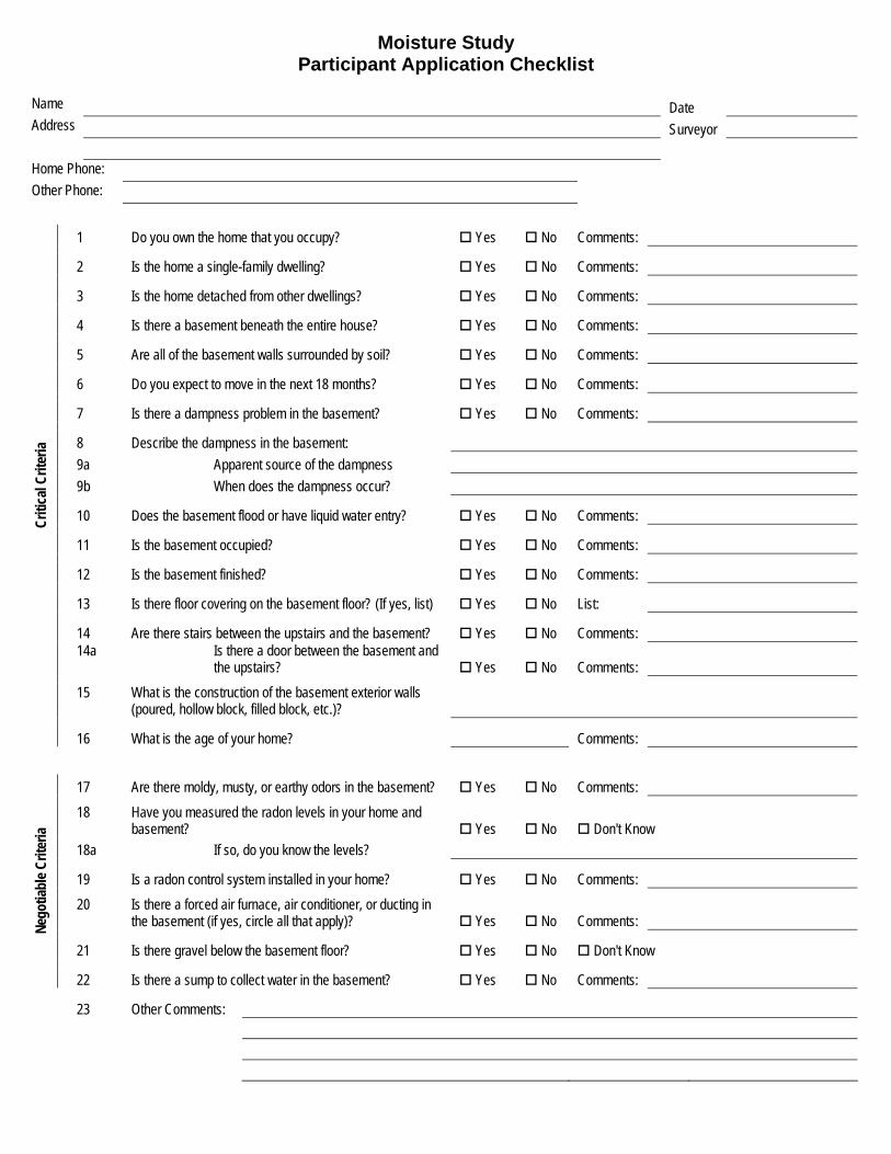
Moisture Study Participant Application Checklist
Name Date Address Surveyor Home Phone: Other Phone:
1 Do you own the home that you occupy? Yes No Comments: 2 Is the home a single-family dwelling? Yes No Comments: 3 Is the home detached from other dwellings? Yes No Comments: 4 Is there a basement beneath the entire house? Yes No Comments: 5 Are all of the basement walls surrounded by soil? Yes No Comments: 6 Do you expect to move in the next 18 months? Yes No Comments: 7 Is there a dampness problem in the basement? Yes No Comments: 8 Describe the dampness in the basement: 9a Apparent source of the dampness 9b When does the dampness occur? 10 Does the basement flood or have liquid water entry? Yes No Comments: 11 Is the basement occupied? Yes No Comments: 12 Is the basement finished? Yes No Comments: 13 Is there floor covering on the basement floor? (If yes, list) Yes No List: 14 Are there stairs between the upstairs and the basement? Yes No Comments: 14a Is there a door between the basement and
the upstairs? Yes No Comments: 15 What is the construction of the basement exterior walls
(poured, hollow block, filled block, etc.)?
Criti
cal C
riter
ia
16 What is the age of your home? Comments:
17 Are there moldy, musty, or earthy odors in the basement? Yes No Comments: 18 Have you measured the radon levels in your home and
basement? Yes No Don't Know 18a If so, do you know the levels? 19 Is a radon control system installed in your home? Yes No Comments: 20 Is there a forced air furnace, air conditioner, or ducting in
the basement (if yes, circle all that apply)? Yes No Comments: 21 Is there gravel below the basement floor? Yes No Don't Know
Nego
tiabl
e Crit
eria
22 Is there a sump to collect water in the basement? Yes No Comments: 23 Other Comments:

Phone Interview Occupant Name ________________________ Date _______________ Intro to Project
• Partnership with PADEP, USEPA, and Auburn Univ. to study moisture reduction in basements using standard radon control systems
• Study length 12 - 18 months • No cost to occupants • Intensive monitoring of moisture, radon, temp, weather and others with installed
instrumentation • 3-day set-up of instrumentation, most in basement some outside and upstairs • Will require putting small temporary holes in walls and floor of basement; running
cables, hanging instruments • Periodic visits to home by PADEP staff member (max: 1 to 2 times per week) to check
instruments, conduct other tests and measurements • Occupants will be asked to keep a diary of activities and unusual conditions • Installation of an active soil depressurization (ASD) radon control system (2-3 days) to
reduce indoor radon and moisture levels. Requires installing 3-4" PVC pipe through floors/walls and routing to a small fan in the attic or garage
• System will be turned on and off on a schedule ranging from 12 hrs to 2 or 3 weeks during the project
• At conclusion of project, all instrumentation will be removed, holes will be repaired • Control system will remain with the house (unless occupants prefer it to be removed)
Additional Information
• Verify questionable data • Home Construction • Approximate size • Number of stories • Elaborate on dampness problem in basement • Basement Details • Occupancy patterns and activities • Pets • Storage • Wall and floor finishes • Name of builder • Days/Hours of access to home • Radon testing • Walk-through schedule

Main Survey - 5
WALK-THROUGH CHECKLIST PENNSYLVANIA HOUSES Name: __________________________________ House ID ___________ Address: __________________________________ Date _______________ __________________________________ Time _______________ __________________________________ Technician(s): ________________________________ Occupant Information 1. Occupants a. Number of occupants _______________ [no. of children _______] b. Number of smokers _________________ [type of smoking & frequency _________________________] 2. General Indoor Environmental Quality: a. Complaints about the air (stuffiness, odors, respiratory problems, watery eyes, etc.): b. Any indications of mold, moisture problems, humidity, or condensation: c. Do the windows fog during the heating season: d.. Has home experienced flooding, water leaks, or sewage backup from inside or outside that caused standing water
damage: 3. Number of plants in the home: 4. Other: a. Photographs of the house during construction. b. Unique features of the house. c. Hours during which house is available for visitations. - Alternative phone numbers: d. Consent to drill inspection holes and install instrumentation EPerm Radon Measurements 1. Test No. 1 Sampling dates _____________________________________________________ Sampling location ___________________________________________________ Radon concentration (pCi/l) ___________________________________________ 2. Test No. 2 Sampling dates _____________________________________________________ Sampling location ___________________________________________________ Radon concentration (pCi/l) ___________________________________________ Temperature / RH Measurements First Floor Location: __________________________________________ Temp ______ RH ______ Basement Location: __________________________________________ Temp ______ RH ______ Outdoor Location: __________________________ _________________Temp ______ RH ______

Main Survey - 6
BASIC HOUSE INFORMATION 1. Year house built _________ [remodeling date _______________] 2. Domestic water source: G municipal surface G municipal well G private on-site well G other: ____________________________________________________ 3. Building construction [complete drawings of site, floor plans, and elevations] Superstructure a. Number of stories above grade: _____________________ b. Construction type and materials: ____________________________________________________________________ c. Estimated leakiness of shell: G tight G moderate G leaky d. Other features: __________________________________________________________________________________ Substructure G Full basement (basement extends beneath entire house) G Full crawlspace (crawlspace extends beneath entire house) G Full on-grade (floor extends beneath entire house) G House elevated above ground on piers G Combination basement and crawlspace G Combination basement and on-grade G Combination on-grade and crawlspace G Combination on-grade, basement, and crawlspace G Other -- specify: ________________________________________________________________________________ 4. Mechanical and combustion appliances (type, fuel, location) a. exhaust fans ___________________________________________________________________________________ b. clothes dryer (vent location)_______________________________________________________________________ c. clothes washer __________________________________________________________________________________ c. forced air furnace _______________________________________________________________________________ d. domestic hot water heater _________________________________________________________________________ e. air conditioning ________________________________________________________________________________ f. woodstove/fireplace _____________________________________________________________________________ g. whole house/attic fans ___________________________________________________________________________ 5. Existing radon control measures Type and description: _______________________________________________________________________ _______________________________________________________________________ Date installed: _______________________________ 6. Other moisture producing equipment (humidifier, steam room, etc.): __________________________________________ 7. Signs of mold or moisture damage indoors: ______________________________________________________________ 8. Condition of gutters and downspouts: __________________________________________________________________ 9. Drainage and grading around house: ___________________________________________________________________ 10. Signs of water damage on outside of building: ____________________________________________________________ 11. Location for instrumentation: ________________________________________________________________________

Basement Survey - 7
BASEMENTS 1. Usage: [occupied, unoccupied] _______________________________________________________________________ 2. Access to basement: [door, hatch, etc.] _________________________________________________________________ 3. Depth of basement floor below grade __________________________________________________________________ 4. Accessibility to floors and walls: _____________________________________________________________________ a. Storage or other items in basement: _________________________________________________________________ 5. Basement Walls: a. Foundation materials G hollow block [filled ____] G poured concrete G solid block G field stone G other: ______________________________________________________________________________________ b. Exterior/interior insulation: ________________________________________________________________________ c. Finish materials (frame, stucco, etc.): ________________________________________________________________ d. Interior load-bearing walls: _______________________________________________________________________ e. Visible openings to soil _______________________________________________________________________ _______________________________________________________________________ f. Signs of moisture/mold: _______________________________________________________________________ _______________________________________________________________________ g. Windows: _____________________________________________________________________________________ 6. Basement Floor: a. Materials G poured concrete slab [aggregate layer ________________________________________________________] G block, brick, stone: ___________________________________________________________________________ G exposed soil G other: ______________________________________________________________________________________ b. Finish materials (paint, carpet, linoleum, etc.): _________________________________________________________ c. Visible openings to soil _______________________________________________________________________ _______________________________________________________________________ e. Signs of moisture: ______________________________________________________________________________ ______________________________________________________________________________ 7. Tightness of floor between basement and first floor: G tight G moderate G leaky 8. Fireplace structure: ________________________________________________________________________________ 9. Forced air HAC system or ductwork in basement: ________________________________________________________ 10. Water Drainage: a. sump (pump: yes/no): ________________________________________________________________________ b. footer drain [exterior, interior, location ____________________________________________________] c. perimeter (french) drain d. floor drains 11. Dehumidifier usage and information: __________________________________________________________________

Crawlspace Survey - 8
CRAWLSPACES 1. Usage: __________________________________________________________________________________________ 2. Access to crawlspace (door, hatch, etc.): ________________________________________________________________ 3. Accessibility to floors and walls: ______________________________________________________________________ 4. Depth below grade ________________ft. [headroom _____________in] 5. Crawlspace Walls: a. Foundation materials G hollow block [filled ____] G solid block G poured concrete G field stone G other: ______________________________________________________________________________________ b. Finish materials ________________________________________________________________________________ c. Support piers in crawlspace: ______________________________________________________________________ d. Visible openings to soil _______________________________________________________________________ _______________________________________________________________________ 6. Crawlspace Floor: a. Materials G poured concrete slab [aggregate layer ________________________________________________________] G plastic sheet or other membrane: _________________________________________________________________ G block, brick, stone: ___________________________________________________________________________ G exposed soil G other: ______________________________________________________________________________________ b. Visible openings to soil _______________________________________________________________________ _______________________________________________________________________ 7. First Floor : a. Materials: _____________________________________________________________________________________ b. Tightness of floor between crawlspace and first floor: G tight G moderate G leaky 8. Forced air HAC system or ductwork in crawlspace ________________________-______________________________ 9. Crawlspace vents [number __________________, location _______________________________________________]

On-Grade Survey - 9
ON- OR NEAR-GRADE FLOORS 1. Usage: __________________________________________________________________________________________ 2. Accessibility to floor/walls from inside: ________________________________________________________________ outside: ________________________________________________________________ 3. Floor a. Materials G poured concrete slab [aggregate layer ________________________________________________________] G block, brick, stone: ___________________________________________________________________________ G exposed soil G other: ______________________________________________________________________________________ b. Elevation of floor relative to surrounding soil: ________________________________________________________ c. Insulation around perimeter of floor: ________________________________________________________________ d. Visible openings to soil _______________________________________________________________________ _______________________________________________________________________ e. Describe floor/wall interface: ________________________________________________________________ ________________________________________________________________ 4. Interior load-bearing walls: __________________________________________________________________________ 5. Location of forced air HAC system ductwork: ___________________________________________________________ 6. Fireplace structure: ________________________________________________________________________________ 7. Water Drainage: a. footer drain [exterior, interior, location ____________________________________________________] b. floor drains Walk-through Checklist.doc 2/4/05
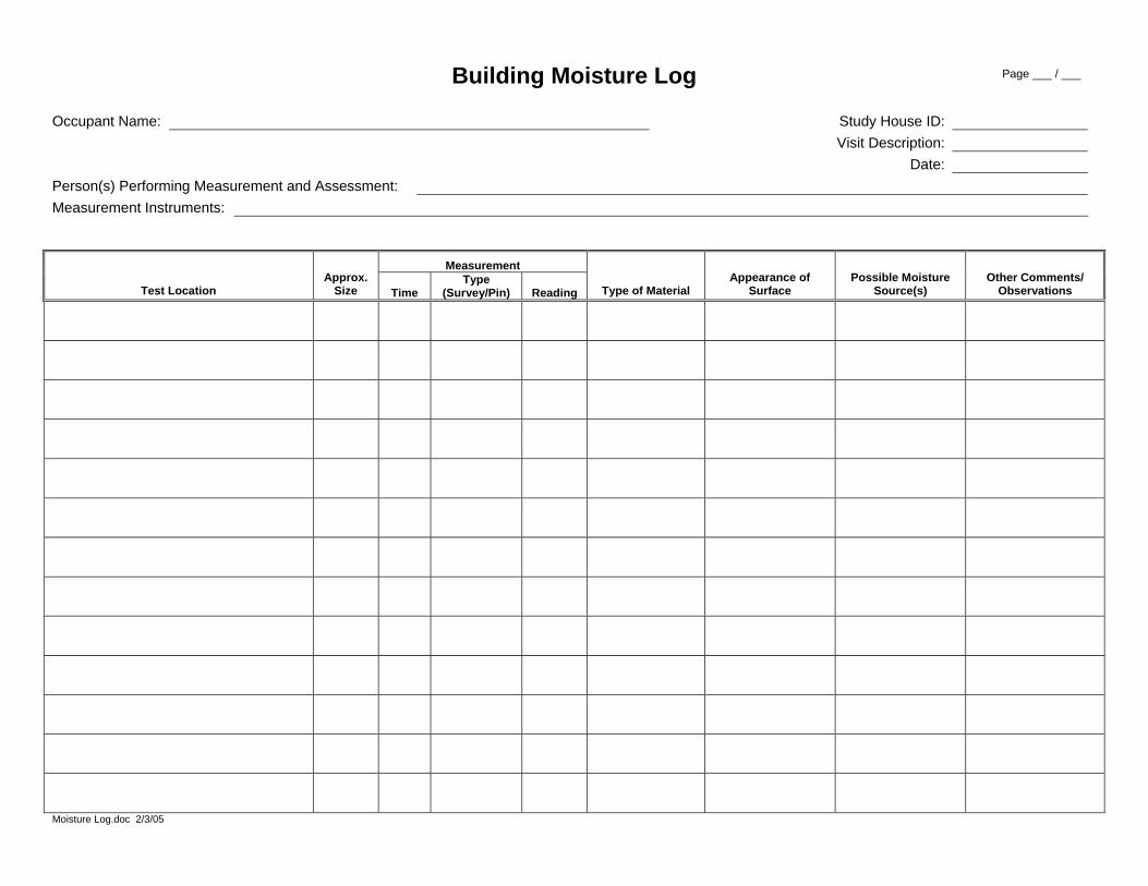
Building Moisture Log Occupant Name: Study House ID:
Visit Description: Date:
Person(s) Performing Measurement and Assessment: Measurement Instruments:
Measurement
Test Location Approx.
Size Time Type
(Survey/Pin) Reading Type of Material Appearance of
Surface Possible Moisture
Source(s) Other Comments/
Observations
Moisture Log.doc 2/3/05
Page ___ / ___

TEMPORARY USE PERMIT For purposes of this agreement: 1) An "occupant" is a person legally entitled to possession of the premises. 2) An "investigator" is an employee or representative of: the Southern Regional Radon Training Center
(Auburn University) or the State of Pennsylvania under the sponsorship of the U.S. Environmental Protection Agency.
The occupant of the premises located at ____________________________________________________________________________________, grants permission to the investigator to enter such premises from (date) __________________ to (date)_________________, between the hours of _________________ and _________________, for the purpose of conducting research on the entry and accumulation of moisture and radon in dwellings, and on innovative methods to reduce indoor concentrations of these pollutants. The occupant understands that the work is experimental in nature, that testing or installation of equipment may cause a temporary increase in moisture or radon concentrations and that the investigators cannot promise the success of any method to reduce indoor moisture or radon concentrations. Any data developed from research conducted on the occupant's premises will be the property of the investigators and may be made available to the public in statistical form, without the occupant's name and address. Upon request, the investigators shall give the occupant a copy of the data. The investigators assume no responsibility to provide information at any particular time or in any specific manner. The occupant understands that the investigators make no warranty, express or implied, that the information provided to the occupant or developed by the research is accurate, complete, or useful. Any system installed to control indoor pollutant levels will be at no cost to the occupant and will remain with the residence upon project completion. Installation is subject to prior approval by the occupant. The occupant understands that the investigators will exercise reasonable care: (1) not to injure the occupant, the occupant's guests, the occupant's property, or the premises; and (2) not to interfere with the occupant's use of the premises except as necessary to undertake the actions provided in this agreement. The investigators will make a reasonable effort to repair damage to the premises caused by the testing or installation work. The occupant shall indemnify, hold harmless and defend the investigators from any and all claims and suits for any reason whatsoever arising out of the actions permitted herein. Dated this __________ day of _________________, 20___ By ________________________________________ ________________________________________ Occupant(s) ________________________________________ Investigator Temporary Use 8.doc 01/31/2005

Data Logger Description __________________________ House ID ________ Page __/__
SENSOR, WIRING, and DATALOGGER LOG
Data Logger Description & Serial Number ___________________ House ID _______________ Multiplexer Description & Serial Number ____________________ Location _____________________________________________ Channel
No. Sensor Description Serial
No. Sensor Location Wire No.
Date Installed
Installer Initials
DATALOGGER
P1
P2
P3
P4
1H
1L
2H
2L
3H
3L
4H
4L
5H
5L
6H
6L
7H
7L
8H
8L

Data Logger Description __________________________ House ID ________ Page __/__
Channel No. Sensor Description
Serial No. Sensor Location
Wire No.
Date Installed
Installer Initials
MULTIPLEXER
1H
1L
2H
2L
3H
3L
4H
4L
5H
5L
6H
6L
7H
7L
8H
8L
9H
9L
10H
10L
11H
11L
Data Logger Description __________________________ House ID ________ Page __/__
Channel No. Sensor Description
Serial No. Sensor Location
Wire No.
Date Installed
Installer Initials
12H
12L
13H
13L
14H
14L
15H
15L
16H
16L
17H
17L
18H
18L
19H
19L
20H
20L
21H
21L
22H
22L
23H
23L
24H
24L

Data Logger Description __________________________ House ID ________ Page __/__
Channel No. Sensor Description
Serial No. Sensor Location
Wire No.
Date Installed
Installer Initials
25H
25L
26H
26L
27H
27L
28H
28L
29H
29L
30H
30L
31H
31L
32H
32L

EVENT AND ACTIVITY LOG HOUSE ID __________ OCCUPANT NAME _____________________
Examples of Important Events or Activities to Record: ● Heavy Rain or Snow or Stormy Conditions ● Extended Use of Exhaust Fans ● Flooding ● Carpet or Rug Cleaning ● Power Outages ● Many Open Windows or Doors ● Fireplace Use ● Parties (or other large gathering of people) Questions or Problems? Call Bob Lewis, PADEP, 783-4870, or Brad Turk, EBSI, 866-426-0723
DATE TIME DESCRIPTION OF EVENTS OR ACTIVITIES

House Visit Log EPA Moisture Study
House PA-03
Name________________
Address______________________ Address______________________ Phone___________________ (hm) Phone___________________ (wk)
Date/Arrival time: _____________/_______ Download info: Data Logger # Download time Time Difference Initials PC vs Station 1 _____________ ____________ ______ 2 _____________ ____________ ______ Pump info: Pylon AB-5/PRD Air Pump Location Flow Rate Flow Rate Initials Serial # Serial # current (cc/min) last week (cc/min) 429 / 9 Floor C1 ___________ ___________ ______ 694 / 5 (258) Wall W14 ___________ ___________ ______ 441 / 372 6 ASD Exhaust ___________ ___________ ______ Comments/Observations: _____________________________________________________________________ __________________________________________________________________________________________ __________________________________________________________________________________________ __________________________________________________________________________________________ __________________________________________________________________________________________ __________________________________________________________________________________________ __________________________________________________________________________________________ __________________________________________________________________________________________

Grab Samples
Residence: ___________________ Date:____________ Sample each unique building zone to determine if any building zones have relatively high indoor radon that would help identify a predominant area of radon entry. Sample under normal house conditions, i.e. no increased house depressurization.
House Location Cell S/N Stop Time Result Basement First Floor Second Floor Garage Crawl Space Slab-on-grade Over Crawl Space
To simulate maximum heating season depressurization, use fan to depressurize basement to about –10 Pa. This will encourage more rapid radon entry and swamp variable environmental effects (wind).
Test Holes
Location Cell S/N Stop Time Result F1 F2 F3 F4 F5 F6 F7 F8 F9 F10 W1 W2 W3 W4 W5 W6

Grab Samples, Cont.
Suspected Entry Points
Location Cell S/N Stop Time Result
Miscellaneous
Location Cell S/N Stop Time Result If grab sample results are greater than room air samples and pressure field at that point is positive, then system performance should be boosted. Grab Samples.Doc

Mitigation Cycling Pattern Log ON OFF
PA03 • Fully Open 3 Valves • Open Sump Lid• Turn Fan On • Turn Fan Off• Close Sump Lid • Completely Close 3 Valves• Record Date/Time • Record Date/Time
On #1 Off #1 On #2 Off #2 On #3 Off #3 On #4 Off #4Scheduled: Date
TimeActual: Date
TimeName
On #1 Off #1 On #2 Off #2 On #3 Off #3 On #4 Off #4Scheduled: Date
TimeActual: Date
TimeName
On #1 Off #1 On #2 Off #2 On #3 Off #3 On #4 Off #4Scheduled: Date
TimeActual: Date
TimeName
Questions?Bob Lewis & Matt Shields, PADEP: 783-4870Brad Turk, EBSI: 1-866-426-0723
3-day Cycling - 4 Repetitions (24 days)
7-day Cycling - 4 Repetitions (56 days)
24-hour Cycling -- 4 Repetitions (8 days)

Ventilation Measurement Log Technicians: House ID: House Conditions & Notes: Test Set-up Date/Time: ASD Condition (Off/On): Test Stop Date/Time:
Tracer Sources
Download Heater ID Vial ID Location
Heater Temp Setting
Hobo Clock OK?
Hobo LED On? Date / Time File Name Comments
Samplers Sampler Case ID
Sample Bag ID
Calib Sample? Sample Location
Pump Flow OK?
Timer Clock OK?
Timer Program OK?
Sample Start Day / Date / Time
Sample StopTime Comments
/ / / / / / / / / / / / / / /
Ventilation Log.doc 12/10/05

Pressure Field Extension Measurements Technician(s): House ID: Date: Description of House/Mitigation Conditions: HVAC On HVAC Off
ΔP (Pa) or Smoke Movement
Bsmt Ref ΔP (Pa) or Smoke Movement
Bsmt Ref
Test Location/ID ASD On ASD Off ASD On ASD Off
Basement-1st Flr
Basement-Outdoor PFE_Form.doc 8/18/05
APPENDIX C House Selection Criteria
Exploratory Study of Basement Moisture During Operation of ASD
Radon Control Systems
Contractor Report to EPA
December 6, 2007

Appendix C – House Selection Criteria Contractor Report to EPA: Basement Moisture & Radon During ASD
1 / 2
The following list of house selection criteria was included in a flyer to solicit participation in the study. In addition to the prioritized list of criteria, the rationale for requiring/including are provided. U.S. EPA/Auburn University Moisture Study The U.S. EPA and Auburn University are conducting a 2-year field study to evaluate the use of radon mitigation techniques to control moisture entry and accumulation in basement houses. Research has linked dampness in houses with a number of debilitating health effects, including asthma. The most common and successful mitigation system, active soil depressurization, will be used in three homes to study moisture movement through basement walls and floors as the system is re-configured and cycled on/off. Measurements of environmental conditions, air pressure and flows, and house conditions will be performed in each house for the duration of the study. If this approach is successful in reducing moisture levels, it may have broad application for improving indoor air quality in many homes nationwide. Because of the complexity in conducting accurate measurements, houses participating in this study must meet the following criteria, grouped by priority:
House Selection Criteria Critical Criteria (participating houses must meet these criteria) $ Owner-Occupied (or Unoccupied) Single-Family, Detached Residence - It is important to simplify
occupancy conditions and agreements/understandings with the occupants $ Full-depth Basement Beneath the Entire House - Basement homes have greater surface contact with
the soil and tend to be influenced more by conditions in the soils and materials around the building. Full basements buried to depth of 5 to 6 feet below grade on all sides are simpler to study and understand. Foundations that also include crawlspaces, slab-on-grade, and walk-out basements are much more complicated constructions to understand and analyze. Houses with an attached garage having a slab-on-grade are acceptable.
$ Expected Residency of 18 Months - Residents that move during the period of active monitoring and
measurements may significantly disrupt data collection during this important phase of the project. $ Evidence of Persistent Moisture Entry (Dampness) into the Basement - Short-term variations in
moisture entry can confound analysis of the effectiveness of the intervention technique. Therefore, homes that appear to have less fluctuation in moisture entry would be better candidates for this study.
$ No Liquid Water Entry or Unusual Moisture Sources - Homes with significant liquid water entry due to
leaks, major drainage problems, or very high water tables should not be selected since ASD is unlikely to be successful in these conditions. Houses where the water table is greater than 25 feet below the basement slab are preferred.
$ Unoccupied and Mostly Unfinished Basement - The requirement for an unoccupied and minimally
finished basement reduces variability in moisture response due to occupant activities and different finishes and furnishings. An unfinished basement also affords better access to basement surfaces for investigators. Basements must be able to be isolated from upper levels of the building, for example by a door.

Appendix C – House Selection Criteria Contractor Report to EPA: Basement Moisture & Radon During ASD
2 / 2
$ Poured Basement Walls and Floor avoid the complicated air flow pathways in blocks. At least one study house must meet this criteria. However, two houses with open core block walls will probably also be selected into the study to avoid excluding construction that may be more susceptible to moisture entry.
$ Older than Three Years of Age - The structures should be between three and ten years of age. Homes
newer than three years of age may have residual moisture from construction still stored in concrete and other materials. If this moisture is being released during the study period, moisture measurements will be affected. For more consistency in construction, homes less than ten years of age are preferred, but this is not a strict criteria for selection.
$ No Karst-like Features Affecting Basement Floors or Walls - Solution cavities and other interconnected,
below-ground voids or cavities that are in contact with the basement foundation create in-homogeneities that complicate our understanding of the surrounding soils.
Negotiable Criteria (while important and desirable, strict compliance with these criteria is not required) $ Musty, Moldy, or Earthy Odors in the Basement - An indicator of existing moisture problems. $ Buildings Without an ASD Installed are preferred, although homes with an installed passive stack could
be considered. Homeowners must be willing to have an ASD system installed, or a passive system activated. They must also be willing to have the system cycled on and off for certain periods.
$ No HVAC or Ducts in Basement - To isolate the basement air from the upstairs air, the basement
should not contain HVAC equipment or ducts. $ Gravel that Forms a Capillary Break Below the Slab Floor - As with permeable soils, a gravel layer
generally results in more uniform conditions below the floor. $ No Sumps - Sumps connected to an encircling drain pipe alter the movement of soil air below and
around a building in complex ways. $ Elevated Pre-mitigation Basement Radon Levels - Basement radon levels should be greater than 4
pCi/L and less than 10 pCi/L, while upstairs levels are no more than 4 pCi/l. Radon concentrations and entry rates may be useful as an approximate indicator for soil gas (and soil gas-borne water vapor) movement into a building while ASD systems are cycled on and off. Radon levels must be sufficiently elevated to indicate changes in soil gas entry rates, yet must be low enough in occupied areas so that exposure is minimized when the ASD systems are cycled off.
$ Permeable Soils Around the Building - Permeable native soils (e.g., glacial tills) tend to have better
uniformity in radon levels surrounding the substructure and have more consistent air flow pathways.
$ Geographical Location - To reduce climatic variability, buildings should all be located in close proximity

APPENDIX D ASD System Diagnostics, Design, and
Description Exploratory Study of Basement Moisture During Operation of
ASD Radon Control Systems
Contractor Report to EPA
December 6, 2007

Appendix D – ASD System Diagnostics, Design, and Description Contractor Report to EPA: Basement Moisture & Radon During ASD
1 / 3
ASD Diagnostic and System Design Procedures
The diagnostic procedures employed in this study include the measurement of air
flow and pressure at suction points to enable quantitative characterization of ‘sub-slab’ resistance, and calculation of pipe run resistance, or ‘friction loss’. These two components comprise the total resistance to air flow in an ASD system, which determines the performance (air flow produced) by a particular fan. This process serves as the basis for the system component selection portion of system design.
Air flow and pressure measurement
An apparatus constructed of PVC pipe and a shop-size vacuum cleaner was used for field measurements of air flow and pressure. A Pitot tube was constructed using 2” PVC pipe and 1/8” brass pipe fittings. This device was calibrated against a commercial Pitot tube to derive a flow vs velocity pressure curve for the device. Static pressure was measured in a 4” PVC pipe sanitary “Tee” adapted to seal into a suction hole in a slab or other suction point, and connected to the 2” PVC pipe Pitot tube. The velocity pressure from the Pitot tube and the static pressure in the pipe apparatus were measured with an electronic digital micromanometer.
‘Friction loss’ calculation
Resistance to air flow in plastic pipe was previously determined by ‘bench’ testing 2”, 3” and 4” schedule 40 PVC pipe and assorted common fittings. Using these values, the pipe run resistance or ‘friction loss’ was calculated for proposed pipe runs.
Fan performance determination
The ‘sub slab’ resistance added to the pipe run resistance at a particular air flow yields the total system resistance at that air flow. At least two of these total system resistance values were plotted on log-scale paper with air flow plotted against system static pressure (resistance) on the axes. Already plotted on the graph paper were the performance curves for several common radon fans. These curves were derived by ‘bench’ testing the fans mounted on 4” PVC pipe, with the air flow and static pressure measured in the pipe using the method described above. The intersection of the total system resistance curve and a fan curve indicates the operating point (pressure and air flow) for that fan on that system.
Fan selection
The air flow through the diagnostic apparatus was adjusted to produce the desired degree of depressurization under the slab and/or in the block walls. At that operating level, the air flow or static pressure in the apparatus was used to locate that point on the total system resistance curve. Any fan whose curve crosses the total system resistance curve at or above that operating level will move enough, or more than enough air to produce that level of depressurization. For the purposes of this study, fans were selected which produced more robust depressurization than would commonly be deemed necessary for radon control.

Appendix D – ASD System Diagnostics, Design, and Description Contractor Report to EPA: Basement Moisture & Radon During ASD
2 / 3
ASD System Description
General considerations
As mentioned elsewhere, the ASD systems for the houses in this study were designed to have more robust performance than would usually be considered necessary or desirable simply for radon control. The major reason for this design decision was that optimal ASD operating parameters for moisture control were not known, and the investigators wanted the greater-than-normal performance capability available. A Fantech HP220 fan was selected for all three houses. The intent was to start the systems at full capacity and reduce the extent and strength of the systems’ impact by reducing the number of active suction points and the total system air flow.
In every leg (save one) of each system, a T/RH sensor was installed in the pipe within one foot of the slab or wall penetration. Another T/RH sensor was installed within 2 feet of the discharge end of the pipe in each system.
A condensate drain was installed in each system so that most, if not all, of the condensate draining back down the pipe could be intercepted and re-routed to a sub-slab location rather than allowed to drain back to a suction point. Each drain was equipped with a valve so that the condensate could be directed to either location.
PA01
This house was built with a passive radon vent consisting of 3 inch PVC pipe originating at a “T” in a perforated flexible interior sub-slab drain tile loop located near the wall. The drain tile loop entered a sump from both directions approximately 8 feet from the “Tee.” The PVC vent pipe extended up the basement wall and up through the wall between the garage and the house interior into the attic. A horizontal run of approximately 20 feet terminated approximately 8 feet from the back wall of the house, where the pipe turned up and penetrated the roof. The fan for the study was installed in this last vertical section. The sump was sealed with a gas-tight cover.
The investigation team installed a second suction point directly under the top basement stair landing, and ran the pipe to just below where the original vent pipe turned to enter the wall of the garage. The two pipes were joined at that point with a sanitary “Tee.” Both suction legs had gate valves installed upstream from the junction point and Pitot tubes were installed upstream from the gate valves.
Diagnostic procedures indicated that friction loss in the rather lengthy 3 inch pipe run, although substantial, did not restrict air flow enough so that substitution of larger pipe was required.

Appendix D – ASD System Diagnostics, Design, and Description Contractor Report to EPA: Basement Moisture & Radon During ASD
3 / 3
PA02 A partial passive radon vent system was installed during construction of this house,
but it was terminated where the 3 inch PVC pipe was stubbed up through the slab from an interior flexible perforated drain tile loop. The pipe was capped at this point, which was directly adjacent to a sump in one corner of the basement. A 3 inch rigid PVC perforated pipe entered the sump after passing through/under the footer from outside the wall, where it connected to a “Tee” in what appeared to be an exterior footer drain. The sump bucket was not perforated to communicate with the sub-slab, although sub-slab water could enter the bucket through the hole for the pipe from the exterior drain tile, or through the pipe itself as it was oriented with the holes down. This pipe passed through approximately 8 inches of sub-slab aggregate between the footer and the sump bucket, and was located just below the interior drain tile.
Investigators installed a 3 inch PVC pipe riser on the stub from the interior tile loop, including a Pitot tube and gate valve. They also installed a gas-tight cover on the sump and a 3 inch riser from the cover, also with a Pitot tube and gate valve. At approximately 4 feet above the floor, both risers were connected into a 4 inch PVC manifold which exited the house through the rim joist. The fan was mounted directly outside the wall, and the discharge continued up to above the roof.
The diagnostic and system performance simulation procedures indicated that the sub-slab pressure field would adequately depressurize the interior of the block walls around the entire perimeter of the structure, obviating the need for direct depressurization of the walls themselves. It proved necessary to seal the wall/floor joint, however, as one-half inch polystyrene bead board had been used as expansion joint which allowed unacceptably large air leakage.
PA03
No ‘radon-resistant’ features were originally incorporated into this house, but it did have a retro-fit water control system consisting in part of a perforated drain tile buried in aggregate under the slab within one foot of the back wall. This tile terminated in the gravel in which the perforated sump bucket was set, but did not penetrate the bucket itself. A gas-tight cover was installed on the sump. A sub-slab suction point was installed adjacent to the back wall, with the radon vent pipe almost touching the sub-slab drain tile. The diagnostic procedures had indicated that even a very robust sub-slab pressure field would not produce adequate depressurization in the block walls except at a few places in the back wall. Thus, direct block wall depressurization was utilized, with two suction points on one leg to the front wall, and one suction point on another leg to the back wall. It was diagnostically determined that both wall suction legs operating simultaneously would produce adequate, if not very robust, depressurization in the walls all around the perimeter.
The air flows required for the system to perform adequately necessitated the use of 4 inch pipe in the system, including all three suction legs. Each leg was equipped with a Pitot tube and gate valve as previously described. The main suction pipe exited the structure through the rim joist on an end wall near the back corner, the fan was mounted directly outside and the discharge terminated above the roof.
APPENDIX E Monitoring and Testing Techniques and
Instrumentation Exploratory Study of Basement Moisture During Operation of ASD
Radon Control Systems
Contractor Report to EPA
December 6, 2007

Appendix E – Monitoring and Testing Techniques and Instrumentation Contractor Report to EPA: Basement Moisture & Radon During ASD
1 / 1
Parameter Location Estimated Range
of Values Instrument Technology T -30 – 35°C (-22 – 95°F) Thermistor
Outdoor Air RH 10 – 100% Thin film capacitance
T 10 – 30°C (50 -- 86°F) Thermistor Basement Air
RH 10 – 90% Thin film capacitance
T 10 – 30°C (50 -- 86°F) Thermistor Microclimate Air
RH 10-100% Thin film capacitance
T 10 – 35°C (50 – 95°F) Thermistor Upstairs Air
RH 10 – 90% Thin film capacitance
T 5 – 28°C (41 – 82°F) Thermistor Soil Air
RH 30 – 100% Thin film capacitance
T 10 – 20°C (50 -- 68°F) Thermistor
Temp. & water vapor content
ASD Air RH 20 – 90% Thin film capacitance
Walls 0.1 to 6% MC Wood sensor / heated RH
Floor 0.1 to 6%MC Wood sensor / heated RH
Soil 0.1 to 10%MC Gypsum block
Finishes 5 to 25% MC wood Moisture pin
Moisture storage
Furnishings 5 to 25% MC wood Moisture pin
Walls 10-90%/5 to 25C RH/T – Δ Pv only Diffusion Floor 10-90%/5 to 25 C RH/T – Δ Pv only
Basement air 0.5 - 2000 pCi/L 18 - 74000 Bq/m3 Pulse ion chamber
1st & 2nd floor air " Pulse ion chamber
ASD exhaust 10 – 100,000 pCi/L 370 – 3,700,000 Bq/m3 Scintillation cell, PMT
Sub-slab " Scintillation cell, PMT
Radon Outside wall " Scintillation cell, PMT
Wind speed Outside house 1 0 - 50 m/s Anemometer-AC generator
Wind direction Outside house 1 0 - 360 degrees Vane-potentiometer
Precipitation Outside house 1 0 - 3"/hr Tipping bucket rain gage
Δ P, continuous Various (see meas. descriptions, above)
From +/- 0.1"WC to 5"WC (25 - 1250 Pa) Variable capacitance transducer
Δ P, periodic Pressure field mapping; multiple locations +/- 1"WC (250 Pa) Variable capacitance transducer
(hand-held digital micromanometer)
House air leakage 0.1 – 15 ACH50 Blower door
Flow 0 - 1500 f/m (0 - 7 m/s) Hot wire anemometer Soil gas entry potential (flow & pressure)
Various; (see meas. descriptions, above)
Pressure 0 - 1"WC (0 - 250 Pa) Digital micromanometer (above)
Flow 0 – 200 cfm Pitot tube/digital micro-manometer
Hot wire anemometer ASD system diagnostics & design: Δ P and Pv
Slab, wall (TBD on-site)
Pressure 0 – 3"WC Digital micromanometer

APPENDIX F Description of Electronic Data Files
Exploratory Study of Basement Moisture During Operation of ASD
Radon Control Systems
Contractor Report to EPA
December 6, 2007

Appendix F – Description of Electronic Data Files Contractor Report to EPA: Basement Moisture & Radon During ASD
1 / 1
Project Final Report with Appendices (Microsoft Word [doc] and Adobe Acrobat Reader [pdf]) Following are the files comprising the final report:
Moisture Project Final Report Appendix A - Forms Appendix B - House Selection Criteria Appendix C - ASD Diagnostics Design & Description Appendix D - Monitoring & Testing Appendix E - Description of Electronic Data Appendix F - Conceptual Model Appendix G - 14-day Moisture Analysis Appendix H - Surface Moisture Measurements
Project Data Files (Microsoft Excel [xls])
PA01_ConvertedData_Final.xls: Data collected and recorded by the data loggers on site at house PA01 that has been screened, filtered, converted, and processed. Some invalid or erroneous data values may remain. PA02_ConvertedData_Final.xls: Data collected and recorded by the data loggers on site at house PA02 that has been screened, filtered, converted, and processed. Some invalid or erroneous data values may remain. PA03_ConvertedData_Final.xls: Data collected and recorded by the data loggers on site at house PA03 that has been screened, filtered, converted, and processed. Some invalid or erroneous data values may remain. Pressure_Field_Extension_Data.xls: All pressure differential data recorded during tests of the extent of pressure field caused by the ASD systems at each house. Floor_Wall_Joist_Surface.xls: All measurements of surface moisture from all houses using handheld instruments, conducted periodically throughout the study. Ventilation_Interzonal.xls: Laboratory results of tracer gas concentrations for test from four seasons, along with calculated and summarized ventilation and interzonal flow measurements at all houses. Harrisburg_Weather_Data.xls: Meteorological data recorded at the Harrisburg, PA airport that covers the field testing period of this study. These data were used as a comparison with on-site measurements made at one of the houses (PA01).

APPENDIX G Impact of ASD Operation on
Basement Moisture Conditions
A Conceptual Model Exploratory Study of Basement Moisture During Operation of ASD
Radon Control Systems
Contractor Report to EPA
December 6, 2007

Appendix G -- Impact of ASD Operation on Basement Moisture Conditions: A Conceptual Model Contractor Report to EPA: Basement Moisture & Radon During ASD
1 / 20
Impact of ASD Operation on Basement Moisture Conditions
A Conceptual Model
March 1, 2006 John F. Straube Balanced Solutions Waterloo, Ontario Canada Bradley H. Turk Environmental Building Sciences, Inc. Las Vegas, New Mexico USA
Introduction The EPA has been aware of anecdotal information on the perception of moisture reduction as a result of ASD operation since the beginning of residential radon mitigation in the mid-1980s. Typical comments from occupants of houses with ASD installed pointed out that musty odors in basements were reduced, dehumidifiers operated less frequently, and wood in paneling, furniture and cabinets had shrunk.
Also, researchers conducting mitigation field studies during this period discovered that certain soils below concrete slabs were drying out from continuous operation of ASD systems. In many situations the drying of soil under slabs created void spaces which enhanced the pressure field extension of the ASD system, the differential pressures across the slab and the overall performance of the system.
A simple, conceptual model is needed to describe the flow of water vapor and the air which carries it through the soil near a building and around the basement structure induced by sub-slab depressurization. The general goal of the model in this study is to help understand and predict the impact of sub slab depressurization on the moisture regime within and immediately around a basement. The model will also be used to estimate boundary conditions so that experimental procedures can be developed and instrumentation specified for the field monitoring phase of the project. A fully-developed model is not in the scope of this project.

Appendix G -- Impact of ASD Operation on Basement Moisture Conditions: A Conceptual Model Contractor Report to EPA: Basement Moisture & Radon During ASD
2 / 20
Moisture Storage and Transport The flow of moisture through soil has been extensively studied by many researchers. The flow of gases (particularly unhealthy vapors from man-made organic compounds) has received great attention in the last few decades in response to industrial waste transport. These flows have been driven by natural forces of gravity, capillarity, and concentration gradient. Some research has been conducted on the flow of air and radon gas due to sub slab depressurization. All of this research has concluded that the soil and basement structure has very complex, almost random, variations in properties that result in flow potential variations in the range of two or three orders of magnitude on any given site and as much as 5 or 6 orders of magnitudes between different sites.
Table 1: Moisture Storage Mechanisms
Moisture Form Storage Location
Free water vapor In pore volume (porosity)
Adsorbed water vapor On pore walls (specific surface area)
Capillary condensed water Held in very small pores
Capillary bound liquid water Held by surface tension in pores
Unbound liquid water Held by containment
The moisture content of the soil around a home can vary dramatically with soil type, time of year, site conditions, and basement design. Significant quantities of moisture from all sources can be stored in the soil, and porous building materials such as concrete, wood, and gypsum, by a number of mechanisms. These are summarized in Table 1.
Moisture Storage in Soil and Porous Building Materials To understand these mechanisms it is important to understand the nature of porous building materials and soil. The pores in these materials range in size from a few mm (between crushed stone) to a few nanometers (between gel sheets within hardened cement paste.). Figure 1 provides some definitions used in describing moisture within porous materials. In general, we apply macroscopic material properties to such porous materials by defining a representative elementary volume (REV) that has similar properties regardless of where the boundaries are drawn.

Appendix G -- Impact of ASD Operation on Basement Moisture Conditions: A Conceptual Model Contractor Report to EPA: Basement Moisture & Radon During ASD
3 / 20
Figure 1: Micro-porous material containing some water
In almost all cases, the relative humidity is nearly 100% in the soil around a house, since the moisture from precipitation and ground water are distributed by either vapor or capillary flow.
The moisture storage function of a typical porous material is shown in Figure 2. Water vapor is stored in the pores (a small quantity) and adsorbed to the surface of the porous material. This is the primary storage mechanism up to a moisture content in equilibrium of relative humidity of about 95%. Above this, capillary condensation within pores becomes important and then near 100% capillary storage dominates. From the critical moisture content (Wcrit) to capillary saturation (Wcap) the relative humidity is essentially 100%. Soil is within the range of partially saturated to capillary saturated most of the time in essentially all climates.

Appendix G -- Impact of ASD Operation on Basement Moisture Conditions: A Conceptual Model Contractor Report to EPA: Basement Moisture & Radon During ASD
4 / 20
Figure 2: Moisture Storage Function for hygroscopic porous material
Moisture Transport through Soil and Building Materials Systems Moisture is transported by four primary mechanisms:
1. Liquid flow driven by gravity. Flow is in the vertical direction, but significant deviations can occur when very different liquid flow permeabilities are encountered. Significant pressures are required to drive this flow (gravity head provides the pressure) and flow rate is significant in large pored materials. In most cases gravity flow drives surface and ground water to drains around a home. Gravity flow tends to be sporadic (during and shortly after rainfall and snowmelt events), and when it stops, a significant amount of water remains in the smaller pores of the soil.
2. Capillary flow driven by suction gradients. At lower moisture contents, flow occurs between pores driven by differences in suction pressure. This generally means that water will “wick” from areas of high moisture content to low moisture content, but it also means that materials with fine pores (clay soil, concrete foundations) will exert a strong suction and drive water into the small pores. The smaller the pores, the slower the flow. In the case of clay and concrete capillary flow is quite slow.

Appendix G -- Impact of ASD Operation on Basement Moisture Conditions: A Conceptual Model Contractor Report to EPA: Basement Moisture & Radon During ASD
5 / 20
3. Vapor diffusion driven by vapor pressure gradients. Water and ice will evaporate into unfilled pores. The gas will diffuse through the open pore spaces along a concentration gradient (again, more to less). This process can dominate in large pored materials such as crushed stone since there is little or no capillary suction.
4. Vapor carried along with convective air flow driven by air pressure differences. The air permeability of soil can range over five orders of magnitude, but even small amounts of airflow can transport significant quantities of moisture in vapor form.
Figure 3: Capillary, diffusive, and convective moisture flows in a porous material
As air flows in close proximity to materials, moisture can diffuse as vapor from the surface of the material and from within small pores to the moving air, provided the water vapor pressure of the air is lower than that of the material’s surface. The more surface area exposed to the air flow, the more moisture is transported. Hence, air that is drier than the materials (e.g., soil) through which it flows has the potential to provide excellent drying. If the air is drier than the materials, however, the same mechanism will ensure that the air gains moisture from the material.
Hypotheses It is hypothesized that the drying observed during operation of ASD systems may be attributed to one, or a combination, of several mechanisms. The operation of an ASD may cause three classes of effects due to air flow:
Class 1. Increase the rate of airflow from outdoors to the basement via either the upper levels of the house (including through the rim joist), or through the soil.
Class 2. Increase the rate of airflow from the basement to the soil.
Class 3. Increase the rate of airflow from the outdoors to the vent stack without interacting with the basement air (i.e., air flows only through the soil directly to the ASD suction point).
Class 1

Appendix G -- Impact of ASD Operation on Basement Moisture Conditions: A Conceptual Model Contractor Report to EPA: Basement Moisture & Radon During ASD
6 / 20
Within Class 1, two practical cases exist (Figure 4). ASD operation may alone, or in combination:
1-a) Reduce the basement air relative humidity (and vapor pressure) by increasing the ventilation rate of the basement with drier air that is indirectly pulled by the ASD from outdoors during dry weather, or from dehumidified interior spaces during hot-humid conditions. This mechanism acts by reducing the indoor basement water vapor concentration, and hence increasing the magnitude of the vapor diffusion rate from furnishings, interior finishes, and foundation materials (increased rate of drying). The ventilation also acts as a sink for the moisture removed. This mechanism could act quickly, in a matter of days to weeks, as it increases the drying capacity and reduces the indoor humidity within hours.
The additional ventilation air would also have the benefit of diluting the airborne concentrations of bio-contaminants and odor-causing metabolites from microbiological infestation, but has the disadvantage of increasing space conditioning energy.
If the source of ventilation air is the outdoors, it is quite possible to cause wetting of interior finishes and an increase in RH during hot humid weather. Although this possibly damaging scenario must be addressed, in many climates, drying will be predominately outward for many months.
The influence on the swing-season RH inside a basement is a function of outdoor air change rate, moisture production rate, and moisture ad/desorption to building materials within the basement.

Appendix G -- Impact of ASD Operation on Basement Moisture Conditions: A Conceptual Model Contractor Report to EPA: Basement Moisture & Radon During ASD
7 / 20
Figure 4: Class 1 Airflows – Air from outdoors enters the basement by several pathways and is then is exhausted by ASD
1-b) Dry the soil and materials near to foundation walls by increasing the flow rate of dry outdoor air through porous soils and through shrinkage/settling gaps commonly found adjacent to foundation walls. Diffusion and capillary movement of moisture into the foundation from soil surrounding the foundation near the surface would be reduced as the soil moisture content is reduced. Moisture content of interior materials would reduce much more slowly due to this mechanism, as it reduces the wetting potential indirectly (by reducing the moisture content of the source: the soil).
This mechanism may theoretically allow the moving air to collect radon gas or other contaminants (such as water vapor, bio-contaminants) and reduce the basement air quality. However, experience with ASD has not shown a reduction in IAQ, in fact, the opposite is observed. This improvement in IAQ could be due either to the fact that flow scenario 1 b) is not occurring, or that the flow is high enough to dilute and remove indoor air pollutants. Investigations of ASD performance show that, in some cases, radon concentrations in the soil near the building are reduced, presumably by dilution with additional outdoor air drawn through the soil (or by Class 3 flows, below) or with basement air pulled out of the building (2d, below).
Class 2
The natural pressure gradient across the basement walls and floors is from outdoors to indoors for much of the year in many climates. By reversing this natural air pressure gradient ASD operation encourages basement air to flow out through the foundation and into the surrounding materials/soil (Figure 5). This air flow reversal should:
2-a) retard entry of nearly saturated soil air that increases the vapor pressure of the basement air (and hence the RH near the surfaces of basement walls, slabs, and finishes). By reducing this moisture source, a source of wetting is removed, and the interior space RH would drop (as in 1-a) above).

Appendix G -- Impact of ASD Operation on Basement Moisture Conditions: A Conceptual Model Contractor Report to EPA: Basement Moisture & Radon During ASD
8 / 20
ASD Operation
Outdoor Air (drier than
basement air)
Upper level air (drier than basement)
2 c)2 d)
2 a)
2 b)
Figure 5: Class 2 Airflows – Basement air is pulled into the surrounding soil, then is
exhausted by the ASD.
2-b) inhibit the transport into the basement of biocontaminants and odor-causing metabolites from microbes that are formed in the soils and materials surrounding the basement.
2c) dry basement materials, interior surfaces, construction assemblies (e.g., furred wall cavities), finish materials, furnishings, and other 'microclimates' close to exterior walls and floors as drier basement air passes through them and along side them.
2 d) dry the soil surrounding the exterior of the basement with drier interior air. Diffusion and capillary movement of moisture from these materials into the basement walls and floor would therefore be reduced.
Class 3
Finally, in Class 3 airflows (Figure 6), ASD operation would draw air from outdoors through the soil and to the vent stack without interacting with the basement air. This flow mechanism could dry the soil next to the basement wall and slab, and hence reduce basement wetting.

Appendix G -- Impact of ASD Operation on Basement Moisture Conditions: A Conceptual Model Contractor Report to EPA: Basement Moisture & Radon During ASD
9 / 20
Figure 6: Class 3 Airflows – Outdoor air is pulled directly to the ASD suction point
through the surrounding soil and is then exhausted by the ASD.
In all seven possible mechanisms described above the flow paths are generally complex, mostly accidental and unintended, and the pressures driving the flows are very small (that is, less than 10 Pa) and intermittent, depending on weather conditions. It is likely that many of these mechanisms work in combination, to varying degrees, depending on many house, soil, and meteorological conditions.
It is important to recognize that the ASD is only one mechanical air moving appliance involved in most house systems. The operation of forced air conditioning equipment (air handling units for furnaces and air conditioning) combined with leaky ducts and the operation of unsealed combustion appliances can, and often do, induce significant flows (measured in the 10 to 100 liters per second) and pressures (often 10 to 100 Pa). These flows and pressures are, by their very nature, intermittent and their frequency and duration is weather and system dependent.
Figure 7 shows a range of plausible potential flow paths and directions in and around a basement system. The number of flow paths that can exhibit airflow in either direction should be noted.

Appendix G -- Impact of ASD Operation on Basement Moisture Conditions: A Conceptual Model Contractor Report to EPA: Basement Moisture & Radon During ASD
10 / 20
Figure 7: Potential airflow paths and likely direction (ASD on)
Figure 8 shows the mechanisms other than airflow usually at work moving moisture around a basement. It should be noted that moisture is transported from outside to inside below grade. This is the case since the soil almost always has a higher vapor content than indoor levels. Although this is not always true, the exceptions are rare, especially in mixed or warm climates. Moisture flow by diffusion is typically a very small proportion of the total moisture flow across the above-grade enclosure – airflow almost completely dominates the moisture transport.

Appendix G -- Impact of ASD Operation on Basement Moisture Conditions: A Conceptual Model Contractor Report to EPA: Basement Moisture & Radon During ASD
11 / 20
Figure 8: Moisture transport due to non-convective flows
A Simple Model Given some knowledge of the outdoor conditions, transport mechanisms, flow paths, and magnitudes, a simplified model can be used to predict the interior basement water vapor content and RH.
The interior humidity level in a building is in constant flux with the interaction of indoor moisture production, the vapor stored and released from building materials and drying, and the incoming flow of air. The interior vapor pressure, and hence RH, of the basement air can be calculated from the following approximate equation:
[ ]( )T
Wiupupv,soilsoilv,outoutv,basev, Q
G273t462QPQPQPP
×+×+⋅+⋅+⋅= [1]
where:

Appendix G -- Impact of ASD Operation on Basement Moisture Conditions: A Conceptual Model Contractor Report to EPA: Basement Moisture & Radon During ASD
12 / 20
Pv,base , Pv,out, Pv,soil, and Pv,up are the basement, outdoor, soil, and upstairs air vapor pressures respectively [Pa],
Gw is the rate of moisture supply to the basement [kg/hr] due to occupancy and diffusion from the surfaces lining the basement,
ti is the indoor basement temperature [Celsius], and
QT, Qout, Qsoil, and Qup are the volumetric flow rates of all incoming, outdoor, soil, and upstairs air (m3/hr), respectively.
Moisture will desorb or adsorb to the surface materials in the basement in response to the vapor content of the interior air (not the RH).
For water vapor driven by vapor pressure gradients along one dimension, Fick’s law can be written as:
dxdPA
ddw wx ⋅⋅−= μθ
[2]
The quantity of water vapor wx (ng) per unit time (dwx) is water vapor flow in the x direction (m) through an area A (m2) perpendicular to the flow, is equal to the product of the vapor pressure gradient dPw (Pa/m) and the coefficient, µ (ng / m ∙ Pa ∙ s). This coefficient is defined as the average vapor permeability. The negative sign is a consequence of the fact that vapor flows from high vapor pressures to low vapor pressures. The same equation can be rewritten for the other two Cartesian directions, in three dimensional vector notation, or, if useful, in polar coordinates.
Fick's equation can be simplified to give the rate of vapor flow per unit area, the vapor flux, qv (ng/m2 ∙ s) as:
qd = hm · (P1 - Pv,base) [3]
where:
hm is the surface mass transfer coefficient (about 15,000 ng/Pa ∙ s ∙ m2), and
P1 and Pv,base are the vapor pressure of a surface (one of many) and the basement vapor pressure (Pa).
Although the vapor permeance varies with temperature and RH, an average vapor permeability, µ, can be assumed for many practical building science situations, and Fick's law written as:
)PP(lμAQ w,2w,1v −⋅⋅= [4]
where Qv is the time rate of vapor flow, l is the length of the flow path or thickness of the material, and P1 and P2 are the vapor pressures on either side of the material of interest.
It can be observed that the form of Fick's Law for diffusive vapor flow is exactly the same as Fourier's Law for conductive heat flow. In fact, on a general level, conductive heat flow is a

Appendix G -- Impact of ASD Operation on Basement Moisture Conditions: A Conceptual Model Contractor Report to EPA: Basement Moisture & Radon During ASD
13 / 20
diffusive flow process, just like vapor flow, and water and air flow in porous media. Therefore, all of the same forms of equations can be used with different variable names
The vapor pressure of the surface of a material can be found from its RH and temperature. The moisture content of each material is a specific function of relative humidity (see Figure 4??????) and the vapor pressure calculated from
P1 = RH(w)· Pws(T) [5]
where:
RH(w) is the relative humidity as a function of moisture content (w),
Pws(T) is the saturation vapor pressure (Pa).
A useful approximate equation for saturation vapor pressure (Pa) over water at a temperature T (in Kelvin) is:
Pws(T)= 1000· e (52.58 - 6790.5
T - 5.028 ln T) [Pa] [6]
where T is the temperature (Kelvin).
The RH of the soil can often be assumed to be at an RH near 100%.
Because a rigorous and reliable theory has yet to be developed, unsaturated flow is often modeled using a phenomenological approach using a moisture content dependent moisture diffusivity, i.e.:
ml = -Dl (w)·∇ w + DT,l (w)· ∇T [7]
where:
ml is the liquid moisture mass flux density (kg/m2·s),
Dl (w) is the moisture content dependent liquid moisture diffusivity (m2/s),
DT,l (w) is the moisture content dependent thermal liquid diffusivity (m2/ (K·s)), and
w is the moisture content (kg/m3).
As for pure Fickian diffusion, the second term (called thermal diffusion or Soret effect) is usually ignored because its effect is one to several orders of magnitude smaller than the isothermal liquid diffusivity. The thermal diffusivity should not be confused with the very significant effects of temperature on vapor and adsorbed moisture flow and the somewhat important impacts of temperature on viscosity and surface tension.
Flow by capillarity and vapor diffusion through solid materials to their surfaces is complex, and dynamic, but this can be simplified by lumped capacitance models for specific circumstances. Computer models such as WUFI have been field verified to have most of the

Appendix G -- Impact of ASD Operation on Basement Moisture Conditions: A Conceptual Model Contractor Report to EPA: Basement Moisture & Radon During ASD
14 / 20
proper physics and numerical capability to predict heat and moisture fields due to liquid transport and vapor diffusion.
Model Results: Example Outputs Based on Class 1 air flows and the above relationships, basement moisture levels have been modeled for a hypothetical structure in Harrisburg, Pennsylvania (Appendix A). Meteorological data are from Typical Meteorological Year (TMY2) for Harrisburg, summer and fall indoor temperatures and RH are from preliminary monitoring in three Harrisburg study houses, while other data are best estimates (Table 2).
The model does not account for storage, and hence is not dynamic. However, Class 1 airflows are not sensitive to storage, and longer term (weeks) outdoor average conditions were used to “smear” short term variations. The airflow is driven by a number of forces, and has been left as a primary variable. The other important variable is the moisture from other sources, including evaporation from wet materials, human use or occupancy, and diffusion through the wall and floor.
The model assumes that diffusion into the basement is restricted by a one perm resistance. This resistance could be provided by a poor quality poured concrete wall or a block wall. This source of moisture is considered in separate calculations, and is generally not an important source of moisture.
Figure 9 shows the resulting equilibrium RH in the basement air during January for four indoor moisture production rates (including diffusion, occupancy, etc.), and assumes that all air entering the basement is from outdoors. In this representation, additional dry (low absolute humidity ratio) outdoor air during the winter creates a large reduction in basement RH. Adding warm, humid (high absolute humidity ratio) outdoor air in the summer months has less of an impact. In general, these same seasonal differences cause the equilibrium RH in the basement to be lower in the winter and higher in the summer.
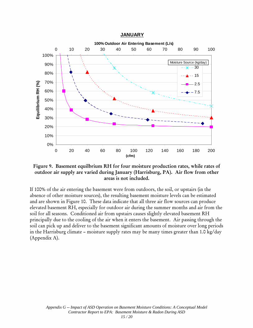
Appendix G -- Impact of ASD Operation on Basement Moisture Conditions: A Conceptual Model Contractor Report to EPA: Basement Moisture & Radon During ASD
15 / 20
0%
10%
20%
30%
40%
50%
60%
70%
80%
90%
100%
0 20 40 60 80 100 120 140 160 180 200(cfm)
Equi
libriu
m R
H (%
)
0 10 20 30 40 50 60 70 80 90 100100% Outdoor Air Entering Basement (L/s)
30
15
2.5
7.5
JANUARY
Moisture Source (kg/day)
Figure 9. Basement equilbrium RH for four moisture production rates, while rates of outdoor air supply are varied during January (Harrisburg, PA). Air flow from other
areas is not included.
If 100% of the air entering the basement were from outdoors, the soil, or upstairs (in the absence of other moisture sources), the resulting basement moisture levels can be estimated and are shown in Figure 10. These data indicate that all three air flow sources can produce elevated basement RH, especially for outdoor air during the summer months and air from the soil for all seasons. Conditioned air from upstairs causes slightly elevated basement RH principally due to the cooling of the air when it enters the basement. Air passing through the soil can pick up and deliver to the basement significant amounts of moisture over long periods in the Harrisburg climate – moisture supply rates may be many times greater than 1.0 kg/day (Appendix A).

Appendix G -- Impact of ASD Operation on Basement Moisture Conditions: A Conceptual Model Contractor Report to EPA: Basement Moisture & Radon During ASD
16 / 20
January April July OctoberUpstairs
Outdoor
Soil
63%72% 77% 77%
17%
37%
77%
52%51% 51% 53% 57%
0%
10%
20%
30%
40%
50%
60%
70%
80%
Bas
emen
t Equ
ilibr
ium
RH
(%)
100% Air Flow to Basement
Figure 10. Basement RH if all entering air originated from one of three areas, for four
different months in Harrisburg, PA.
Since the previous two analyses are limited to single sources of air flow, the more likely scenario of multiple air flow sources was explored (Equation1). In this exercise, diffusion through basement walls and floor was assumed to be 0.6 kg/day, with moisture from other sources incorporated into the air flows entering from the soil, upstairs, and outdoors. Three rates of total air flow (3 L/s – 0.06 ACH, 35 L/s – 0.70 ACH, and 100 L/s – 2.0 ach) were studied while the fraction of air entering from the soil (5%, 20%, 50%), outdoors (10 – 95%), and upstairs was varied. Results for January and July are shown in Figures 11a and 11b.
As in Figure 9, increasing the fraction of outdoor air will tend to dry the basement in the winter and add moisture during periods of warm, humid weather. In addition, an increasing fraction of soil air raises basement moisture, regardless of season. Boosting the total ventilation rate of the basement causes a slight drop in basement moisture as the moisture from diffusion is diluted.
Not only do these data illustrate the relative impacts of varying the incoming air flows, but they also hint at the effects of an operating ASD system. By depressurizing the surrounding soil and possibly further depressurizing the basement, ASD may reduce the fraction of air from the soil and increase the fraction of air from the upstairs and outdoors. ASD systems typically exhaust between 25 cfm (11.8 L/s) and 100 cfm (47.2 L/s) to the outdoor air. Anecdotal information from early radon studies suggests that 5-80% of this air originated in the basement, and was pulled out of the building through cracks and openings in the

Appendix G -- Impact of ASD Operation on Basement Moisture Conditions: A Conceptual Model Contractor Report to EPA: Basement Moisture & Radon During ASD
17 / 20
foundation, into the soil, collected by the ASD suction pipe. This gives a range of 1.25 cfm (0.59 L/s) to 80 cfm (37.8 L/s) of basement air that is exhausted. It is likely that this was made up by unknown fractions of air entering from the outdoors and upstairs (Class 1 flows).
To estimate a possible reduction in basement moisture levels due to operation of the ASD system, a pre-mitigation condition of 3 L/s total entering air flow, comprised of 20% soil air/50% outdoor air/30% upstairs air, was assumed. The ASD system was assumed to increase total ventilation to 35 L/s, eliminate entry of soil air, with the incoming air being equally split between the outdoors and upstairs. The humidity ratio dropped from 6.3 to 4.3 g/kg, while the RH declined from 52 to 35% for January. Calculated reductions were also significant in July: the humidity ratio went from 12.9 to 10.4 g/kg, and the RH from 83 to 67%. The data are also displayed in Figure 11 by the '+' and '×' symbols. These results show the potential for ASD to significantly reduce basement moisture levels under the right circumstances – other starting air flow conditions could diminish or enhance the reductions. While moisture reductions in the basement air during ASD operation have been calculated, drying of the materials in close proximity to the foundation may be even more dramatic and important to indoor environmental quality.
These simple modeling exercises do not account for many of the real-world complexities. e.g.:
• Diffusion rates, although typically small, vary as moisture levels in the indoor air change;
• Moisture levels in the basement and upstairs, and to some extent soil, air are interdependent;
• Outdoor air entering through the surrounding soil may not equilibrate at 100% RH after drying of the soil has begun to occur.
In addition, different structures and finishes on the interior of the basement will change both the airflow and vapor diffusion modes of moisture transport. Concrete block walls are suspected more open for air leakage and vapor diffusion. The addition of interior finishes will generally reduce the airflow and diffusive flow of moisture across the basement. The interior finishes will also tend to increase the moisture storage capacity and change the temperature of the soil around the basement. All of these factors are poorly characterized but likely to change the response of a basement to ASD operation.
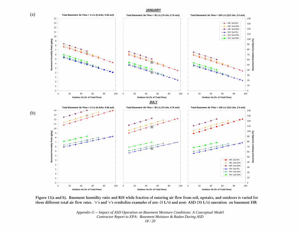
Appendix G -- Impact of ASD Operation on Basement Moisture Conditions: A Conceptual Model Contractor Report to EPA: Basement Moisture & Radon During ASD
18 / 20
Figure 11(a and b). Basement humidity ratio and RH while fraction of entering air flow from soil, upstairs, and outdoors is varied for three different total air flow rates. '×'s and '+'s symbolize examples of pre- (3 L/s) and post- ASD (35 L/s) operation on basement HR
(a)
(b)
Total Basement Air Flow = 3 L/s (6.4cfm, 0.06 ach)
-2
-1
0
1
2
3
4
5
6
7
8
9
10
11
12
13
14
0 20 40 60 80 100
Outdoor Air (% of Total Flow)
Bas
emen
t Hum
idity
Rat
io (g
/kg)
0
10
20
30
40
50
60
70
80
90
100
110
120
130
140
Bas
emen
t Rel
ativ
e H
umid
ity (%
)
HR: Soil 5%
HR: Soil 20%
HR: Soil 50%
Series7RH: Soil 5%
RH: Soil 20%
RH: Soil 50%
Series8
Total Basement Air Flow = 35 L/s (74 cfm, 0.70 ach)
-2
-1
0
1
2
3
4
5
6
7
8
9
10
11
12
13
14
0 20 40 60 80 100
Outdoor Air (% of Total Flow)
Bas
emen
t Hum
idity
Rat
io (g
/kg)
0
10
20
30
40
50
60
70
80
90
100
110
120
130
140
Bas
emen
t Rel
ativ
e H
umid
ity (%
)
HR: Soil 5%
HR: Soil 20%
HR: Soil 50%
Series7RH: Soil 5%
RH: Soil 20%
RH: Soil 50%
Series8
Total Basement Air Flow = 100 L/s (212 cfm, 2.0 ach)
-2
-1
0
1
2
3
4
5
6
7
8
9
10
11
12
13
14
0 20 40 60 80 100
Outdoor Air (% of Total Flow)
Bas
emen
t Hum
idity
Rat
io (g
/kg)
0
10
20
30
40
50
60
70
80
90
100
110
120
130
140
Bas
emen
t Rel
ativ
e H
umid
ity (%
)
HR: Soil 5%HR: Soil 20%HR: Soil 50%RH: Soil 5%RH: Soil 20%RH: Soil 50%
JANUARY
Total Basement Air Flow = 3 L/s (6.4cfm, 0.06 ach)
-2
-1
0
1
2
3
4
5
6
7
8
9
10
11
12
13
14
0 20 40 60 80 100
Outdoor Air (% of Total Flow)
Bas
emen
t Hum
idity
Rat
io (g
/kg)
0
10
20
30
40
50
60
70
80
90
100
110
120
130
140
Bas
emen
t Rel
ativ
e H
umid
ity (%
)
HR: Soil 5%
HR: Soil 20%
HR: Soil 50%
Series7RH: Soil 5%
RH: Soil 20%
RH: Soil 50%
Series8
Total Basement Air Flow = 35 L/s (74 cfm, 0.70 ach)
-2
-1
0
1
2
3
4
5
6
7
8
9
10
11
12
13
14
0 20 40 60 80 100
Outdoor Air (% of Total Flow)
Bas
emen
t Hum
idity
Rat
io (g
/kg)
0
10
20
30
40
50
60
70
80
90
100
110
120
130
140
Bas
emen
t Rel
ativ
e H
umid
ity (%
)
HR: Soil 5%
HR: Soil 20%
HR: Soil 50%
Series7RH: Soil 5%
RH: Soil 20%
RH: Soil 50%
Series8
Total Basement Air Flow = 100 L/s (212 cfm, 2.0 ach)
-2
-1
0
1
2
3
4
5
6
7
8
9
10
11
12
13
14
0 20 40 60 80 100
Outdoor Air (% of Total Flow)
Bas
emen
t Hum
idity
Rat
io (g
/kg)
0
10
20
30
40
50
60
70
80
90
100
110
120
130
140
Bas
emen
t Rel
ativ
e H
umid
ity (%
)
HR: Soil 5%HR: Soil 20%HR: Soil 50%RH: Soil 5%RH: Soil 20%RH: Soil 50%
JULY
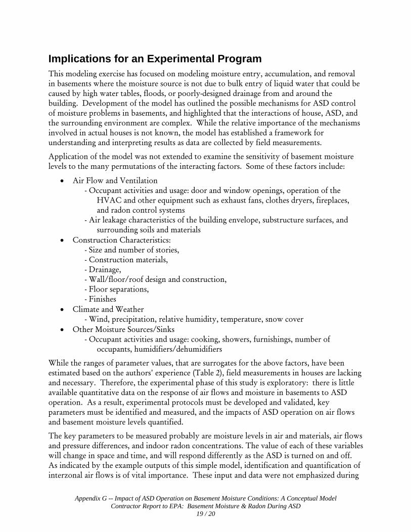
Appendix G -- Impact of ASD Operation on Basement Moisture Conditions: A Conceptual Model Contractor Report to EPA: Basement Moisture & Radon During ASD
19 / 20
Implications for an Experimental Program This modeling exercise has focused on modeling moisture entry, accumulation, and removal in basements where the moisture source is not due to bulk entry of liquid water that could be caused by high water tables, floods, or poorly-designed drainage from and around the building. Development of the model has outlined the possible mechanisms for ASD control of moisture problems in basements, and highlighted that the interactions of house, ASD, and the surrounding environment are complex. While the relative importance of the mechanisms involved in actual houses is not known, the model has established a framework for understanding and interpreting results as data are collected by field measurements.
Application of the model was not extended to examine the sensitivity of basement moisture levels to the many permutations of the interacting factors. Some of these factors include:
• Air Flow and Ventilation - Occupant activities and usage: door and window openings, operation of the
HVAC and other equipment such as exhaust fans, clothes dryers, fireplaces, and radon control systems
- Air leakage characteristics of the building envelope, substructure surfaces, and surrounding soils and materials
• Construction Characteristics: - Size and number of stories, - Construction materials, - Drainage, - Wall/floor/roof design and construction, - Floor separations, - Finishes
• Climate and Weather - Wind, precipitation, relative humidity, temperature, snow cover
• Other Moisture Sources/Sinks - Occupant activities and usage: cooking, showers, furnishings, number of
occupants, humidifiers/dehumidifiers
While the ranges of parameter values, that are surrogates for the above factors, have been estimated based on the authors' experience (Table 2), field measurements in houses are lacking and necessary. Therefore, the experimental phase of this study is exploratory: there is little available quantitative data on the response of air flows and moisture in basements to ASD operation. As a result, experimental protocols must be developed and validated, key parameters must be identified and measured, and the impacts of ASD operation on air flows and basement moisture levels quantified.
The key parameters to be measured probably are moisture levels in air and materials, air flows and pressure differences, and indoor radon concentrations. The value of each of these variables will change in space and time, and will respond differently as the ASD is turned on and off. As indicated by the example outputs of this simple model, identification and quantification of interzonal air flows is of vital importance. These input and data were not emphasized during

Appendix G -- Impact of ASD Operation on Basement Moisture Conditions: A Conceptual Model Contractor Report to EPA: Basement Moisture & Radon During ASD
20 / 20
a planning session by experts, but will provide vital information regarding the supply and removal of moisture with the movement of air.
Response times for air pressure (and air movement) and radon levels are reasonably well-characterized. For example, changes in ASD operation typically causes air pressure changes within seconds to minutes, and changes in radon levels usually within 24 hours. Other effects, such as changes in barometric pressure and outdoor temperature, usually cause responses within minutes to days. Response times in moisture levels due to ASD operation have not been measured, but are expected to vary from hours to months, depending on the materials and the actual airflow paths and rates. The moisture content of the air and at the surface of unfinished wood exposed to the basement air should change quickly, whereas the wood in the center of a stud behind a panel finish may take weeks to react to a significant change in interior air moisture levels. Soil and concrete walls and floors have an even longer time constant, and moisture changes will usually require months or even years to be significant.
It is anticipated that monitoring and analyzing these moisture responses will provide important data on the response behaviors of the assembled building components, and offer insights into the dominant mechanisms for moisture control by ASD. For instance, a very rapid change in air moisture levels probably indicates that drier ventilation air has been introduced. Quick changes in the moisture level of soil or foundation materials will suggest that other air flow paths are participating in the drying.

Appendix G -- Impact of ASD Operation on Basement Moisture Conditions: A Conceptual Model Contractor Report to EPA: Basement Moisture & Radon During ASD
21 / 20
Table 2: Key Model Parameters and Estimated Range of Values
Key Parameters Related
Parameters Estimated
Range of Values Test Procedures/Device(s)
Outdoor 0.03 – 2.0 L/s-m2 * (0.01 -- 0.40 cfm/ft2) (0.05 – 3.0 ach)
• Tracer Gas • Air Leakage Area - Blower Door • Diff. Pressures – Transducer
Upstairs 0.03 – 2.0 L/s-m2 * (0.01 -- 0.40 cfm/ft2) (0.05 – 3.0 ach)
• Tracer Gas • Air Leakage Area - Blower Door • Diff. Pressures – Transducer
Soil:
0.003 – 0.17 L/s-m2 ** (0.7x10⁻⁵ – 0.03 cfm/ft2) 10-10 – 10-5 m3/Pa-s‡
• Diff. Pressures - Transducer • Effective Resistances (floor, soil) • Soil Gas Entry Potential
ASD Air Flow 0 – 50 L/s (0 – 100 cfm)
• Velocity Pressures - Transducer • Diff. Pressures - Transducer • Radon Concentrations - CRM • Tracer Gas
Wind Speed 0 – 30 m/s (0 – 67 mph) Cup Anemometer
Wind Direction 0 – 360 Wind Vane Barometric Pressure
98 – 104 kPa (29 – 31 in Hg) Pressure Transducer
Air Flow In/Out of Basement:
Soil Air Permeability 10-14 – 10-8 m2 Soil Air Permeameter
T -30 – 35°C (-22 – 95°F) Thermistor Outdoor Air: RH 10 – 100% Thin film capacitance
T 10 – 30°C (50 – 86°F) Thermistor Basement Air: RH 10 – 90% Thin film capacitance T 10 – 30°C (50 -- 86°F) Thermistor Microclimate Air: RH 10-100% Thin film capacitance T 10 – 35°C (50 – 95°F) Thermistor Upstairs Air: RH 10 – 90% Thin film capacitance
T 5 – 28°C (41 – 82°F) Thermistor Soil Air: RH 30 – 100% Thin film capacitance T 10 – 20°C (50 -- 68°F) Thermistor
Temperature & Water Vapor Content:
ASD Air: RH 20 – 90% Thin film capacitance
Walls 0.1 to 6% MC Wood sensor / heated RH Floor 0.1 to 6% MC Wood sensor / heated RH
0.1 to 10% MC Gypsum block Soil:
Precipitation 0.25 – 250 mm/day (0.01 – 10 in/day) Tipping Bucket Rain Gage
Finishes 5 to 25% MC wood Moisture pin
Moisture Storage:
Furnishings 5 to 25% MC wood Moisture pin
Walls 10-90%/5 to 25C RH/T – delta Pv only Floor 10-90%/5 to 25 C RH/T – delta Pv only
Diffusion:
* Based on 140 m2 (1500 ft2) basement with 2.44 m (8 ft) ceilings ** Assuming 1 to 50% of incoming ventilation air, at 0.05 to 0.5 ach, is from the soil ‡ Soil gas entry potential

Appendix G -- Impact of ASD Operation on Basement Moisture Conditions: A Conceptual Model Contractor Report to EPA: Basement Moisture & Radon During ASD
22 / 20
EPA Simple Model of a Ventilated Basement
Basement DataLength 9 m 29.5 ft Width 8 m 26.2 ft Height 2.5 m 8.20 ft
Permeance of interior 60 ng/Pa s m2 1.05 US Perms Kraft paper is around 1 permJan Apr Jul Oct
Temperature, C 17 17 21 18Temperature, F 62.6 62.6 69.8 64.4
calculated valuesSaturation, Pa 1928 1928 2474 2053
Area 72 m2 775 ft2
Volume: 180 m3 6366 ft3
Wall: 85 m2 915 ft2
Floor 72 m2 775 ft2
Surface Area: 157 m2 1689 ft2
Upstairs Air Conditions - EstimatedPv,out (Pa) Temp ( C) RH Pv,out, sat (Pa) W (g/kg) Temp (F)
January 990 21 40% 2474 6.1 69.8April 990 21 40% 2474 6.1 69.8July 1336 24 45% 2969 8.3 75.2October 1184 22 45% 2631 7.4 71.6
Weather Conditions, Harrisburg, PA - Outdoor AirPv,out (Pa) Temp ( C) RH Pv,out, sat (Pa) W (g/kg) Temp (F)
January 337 -1.0 59.6% 566 2.1 30.2April 726 9.7 60.6% 1197 4.5 49.5July 1928 24.4 63.6% 3033 12.1 75.8October 1070 12.6 73.6% 1455 6.6 54.7
Soil Air Conditions - EstimatedPv,out (Pa) Temp ( C) RH Pv,out, sat (Pa) W (g/kg) Temp (F)
January 1221 10 100% 1221 7.6 50.0April 1395 12 100% 1395 8.7 53.6July 1928 17 100% 1928 12.1 62.6October 1590 14 100% 1590 9.9 57.2
Soil Air Moisture ContributionIf air flows from outside to the basement through soil and picks up all possible moisture then
kg/day of moisture added to outdoor air by passage through soiland heating to soil temp
cfm L/s L/s-m2 ACH January April July October5 2.4 0.03 0.05 1.3 1.0 0.0 0.8
10 4.7 0.07 0.09 2.7 2.1 0.0 1.620 9.4 0.13 0.19 5.4 4.1 0.0 3.240 18.9 0.26 0.38 10.8 8.2 0.0 6.475 35.4 0.49 0.71 20.2 15.4 0.0 12.0
125 59.0 0.82 1.18 33.7 25.7 0.0 20.0200 94.4 1.31 1.89 53.9 41.1 0.0 32.1
Hence, air flow through soil has the potential to add large amounts of moisture to basementin some situations -- high flow through soil (over 20 cfm) and cooler weather
Total flow through soil
Appendix A: Inputs to Simple Model

APPENDIX H Summary of 14-Day Mean Daily Moisture
Changes Exploratory Study of Basement Moisture During Operation of ASD
Radon Control Systems
Contractor Report to EPA
December 6, 2007

Appendix H – Summary of 14-Day Mean Daily Moisture Changes Contractor Report to EPA: Basement Moisture & Radon During ASD
1 / 3
14-Day Mean Daily Moisture Changes
A 14-day trend analysis was performed on the moisture data from the basement air and wall and floor clusters at each house. Similar to the 7-day analysis, an auto-regression was performed on the first 14-days of cycles at least 14 days in length. Results are aggregated and reported in Figures H1 – H3. Compared with the 7-day analysis, these data typically show smaller rates of change, both during ASD Off (usually increasing) and ASD On (usually decreasing). This result reflects the pattern of moisture levels changing rapidly immediately after a change in ASD system operation followed by a gradually decreasing change over time as the house and materials try to reach a new moisture equilibrium. Sealing of the perimeter wall/floor joint at PA01 appears to have diminished the effectiveness of the ASD system in reducing moisture (Figure H1), perhaps by limiting the amount of basement air passing through this crack and diluting the moisture levels in the surrounding materials.
0.24
-0.06
0.05
-0.37
-0.09
-0.16
0.44
0.200.24
0.13
0.00
-0.06
-0.6
-0.4
-0.2
0.0
0.2
0.4
0.6
0.8
Basement Air Block Walls Slab Floor
Mea
n D
aily
Cha
nge
in R
elat
ive
Hum
idity
(%)
ASD OffASD OnASD Off - Crack SealASD On - Crack Seal
p=0.04074/4>0 4/4<0
p=0.001425/32>0 29/30<0
p=0.000316/16>0 13/24<0
p=0.37282/2>0 1/2<0
p=0.634222/26>0 19/23<0
p=0.0439/12>0 7/18<0
Figure H1. Summary of arithmetic mean daily change for first 14 days of period in basement moisture levels in the air, walls, and slab floor at house PA01 during ASD cycling. The statistical significance of the difference (p) between ‘off’ and ‘on’ is indicated in the box below, along with the number of ‘off’ and ‘on’ cycles (out of total) with a rate of change greater than and less than 0, respectively. For walls and floors, data from a number of different locations are aggregated, as reflected in the total number of cycles. Data include summer and non-summer periods from November 2005 through August 2006.

Appendix H – Summary of 14-Day Mean Daily Moisture Changes Contractor Report to EPA: Basement Moisture & Radon During ASD
2 / 3
0.72
1.44
0.12
-0.32
-1.00
-0.13
-0.65
-1.04
-0.11
0.490.67
0.170.06
-0.18-0.03
-0.37
-0.93
-0.11
-4.0
-3.0
-2.0
-1.0
0.0
1.0
2.0
3.0
Basement Air Block Walls Slab Floor
Mea
n D
aily
Cha
nge
in R
elat
ive
Hum
idity
(%)
ASD OffASD OnASD ReducedSummer ASD OffSummer ASD OnSummer ASD Reduced
p=0.02946/10>0 3/6<0
p=0.019517/18>0 10/12<0
p<.000137/50>0 26/30<0
p=0.02473/3<0
p=0.58463/3>0 0/2<0
p<.000157/60>0 36/36<0
p=0.94281/1<0
p=0.02955/6<0
p<.000117/18<0
p<.000113/15<0
p=0.003614/15>0 6/10<0
p=0.02184/5<0
Figure H2. Mean daily changes for first 14 days of period in basement moisture at house PA02 for air, block walls, and slab floors. These data are for December 2005 through January 2007, and include periods when the ASD operation was reduced to a single pipe. Note the change in scale for the y-axis as compared with house PA01.

Appendix H – Summary of 14-Day Mean Daily Moisture Changes Contractor Report to EPA: Basement Moisture & Radon During ASD
3 / 3
0.49
0.93
0.08
-0.20 -0.12
-0.95
-0.32-0.12
0.21 0.300.07
1.04
0.04 0.150.17
-0.07
0.08
-4.0
-3.0
-2.0
-1.0
0.0
1.0
2.0
3.0
Basement Air Block Walls Slab Floors
Mea
n D
aily
Cha
nge
in R
elat
ive
Hum
idity
(%)
ASD OffASD OnASD ReducedSummer ASD OffSummer ASD OnSummer ASD Reduced
p=0.10546/8>0 4/5<0
p=0.352122/24>0 2/6<0
p<.000142/54>0 33/35<0
p=0.00813/3<0
p=0.31432/4>0 0/1<0
p<.000146/48>0 30/30<0
p=0.95390/1<0
p=0.19013/6<0
p<.000110/18<0
p<.000116/18<0
p=0.076019/26>0 1/7<0
p=0.83230/6<0
Figure H3. Mean daily changes for first 14 days of period in basement moisture at PA03 for December 2005 through January 2007, where single-pipe, reduced ASD operation is included.

APPENDIX I Summaries of Handheld Surface
Moisture Measurement Data Exploratory Study of Basement Moisture During Operation of
ASD Radon Control Systems
Contractor Report to EPA
December 6, 2007

Appendix I – Summaries of Handheld Surface Moisture Measurement Data Contractor Report to EPA: Basement Moisture & Radon During ASD
1 / 5
Surface Measurement Testing Schedules PA01 Testing Schedule Baseline (5/9/2005): No ASD operation 4/4/2006: ASD on 14 days prior to measurements 7/21/2006: ASD on 72 days prior to measurements 10/2/2006: ASD off 6 days prior to measurements PA02 Testing Schedule Baseline (7/14/2005): No ASD operation 3/28/2006: ASD on 14 days prior to measurements 7/19/2006: ASD on 16 days prior to measurements 11/28/2006: ASD off 14 days prior to measurements 12/19/2006: ASD on 21 days prior to measurements PA03 Testing Schedule Baseline (7/18/2005): No ASD operation 4/11/2006: ASD on 14 days prior to measurements 7/20/2006: ASD on 2 days prior to measurements 12/12/2006: ASD off 14 days prior to measurements 01/02/2007: ASD on (modified) 14 days prior to measurements

Appendix I – Summaries of Handheld Surface Moisture Measurement Data Contractor Report to EPA: Basement Moisture & Radon During ASD
2 / 5
Basement Floor Measurement Results Table 1a, Average Basement Floor Moisture (%) Measurements for PA01
Location Baseline 5/9/2005 4/4/2006 7/21/2006 10/2/2006 Avg
SW Perimeter 4.88 3.97 4.77 4.72 4.58 NW Perimeter 4.65 3.84 4.48 4.41 4.34 NE Perimeter 4.48 3.48 4.72 4.38 4.26 SE Perimeter 4.41 3.8 4.38 4.52 4.27 Perimeter Avg 4.61 3.77 4.58 4.51 --- Slab Center 4.36 3.52 4.33 4.45 --- Center & Perimeter Avg. 4.56 3.72 4.34 4.50 --- Table 1b. Average Basement Floor Moisture (%) Measurements for PA02
Location Baseline 7/14/2005 3/28/2006 7/19/2006 11/28/2006 12/19/2006 Average
SW Perimeter 3.32 1.48 3.18 2.80 1.99 2.55 NW Perimeter 3.40 1.32 3.08 No Data 1.94 2.44 NE Perimeter 3.58 1.32 3.00 2.17 1.86 2.39 SE Perimeter 2.77 1.34 2.86 2.89 1.81 2.33 Perimeter Avg 3.27 1.37 3.03 2.62 1.90 --- Slab Center 4.68 3.48 4.68 4.10 3.80 --- Center & Perimeter Avg. 3.98 2.43 3.86 3.36 2.85 --- Table 1c, Average Basement Floor Moisture Measurements for PA03
Location Baseline 7/18/2005 4/11/2006 7/20/2006 12/12/2006 1/02/2007 Avg
SW Perimeter 4.70 3.68 4.46 3.68 3.67 4.03 NW Perimeter 5.06 3.66 4.66 3.84 3.80 4.20 NE Perimeter 4.80 3.56 4.49 3.67 3.70 4.04 SE Perimeter 5.06 4.10 4.96 4.08 4.16 4.47 Perimeter Avg. 4.91 3.75 4.64 3.82 3.83 --- Slab Center 4.03 3.33 3.97 3.50 3.63 --- Center & Perimeter Avg. 4.47 3.54 4.31 3.66 3.73 ---
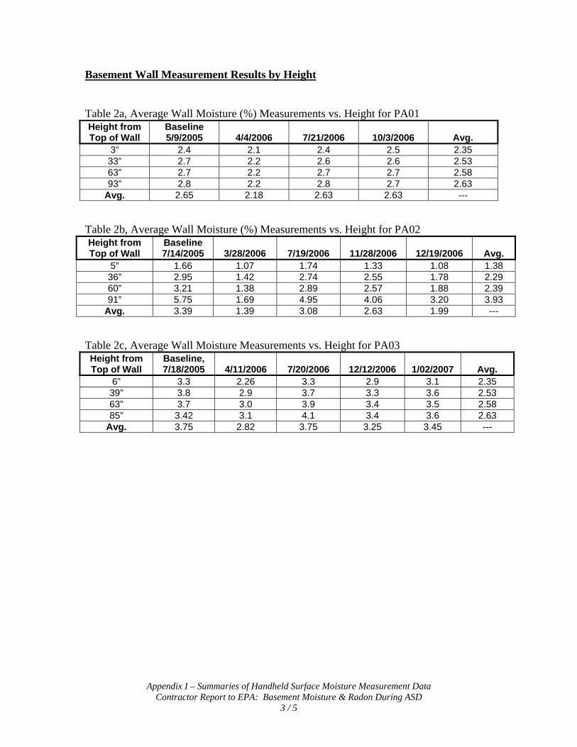
Appendix I – Summaries of Handheld Surface Moisture Measurement Data Contractor Report to EPA: Basement Moisture & Radon During ASD
3 / 5
Basement Wall Measurement Results by Height
Table 2a, Average Wall Moisture (%) Measurements vs. Height for PA01 Height from Top of Wall
Baseline 5/9/2005 4/4/2006 7/21/2006 10/3/2006 Avg.
3” 2.4 2.1 2.4 2.5 2.35 33” 2.7 2.2 2.6 2.6 2.53 63” 2.7 2.2 2.7 2.7 2.58 93” 2.8 2.2 2.8 2.7 2.63
Avg. 2.65 2.18 2.63 2.63 --- Table 2b, Average Wall Moisture (%) Measurements vs. Height for PA02 Height from Top of Wall
Baseline 7/14/2005 3/28/2006 7/19/2006 11/28/2006 12/19/2006 Avg.
5” 1.66 1.07 1.74 1.33 1.08 1.38 36” 2.95 1.42 2.74 2.55 1.78 2.29 60” 3.21 1.38 2.89 2.57 1.88 2.39 91” 5.75 1.69 4.95 4.06 3.20 3.93
Avg. 3.39 1.39 3.08 2.63 1.99 --- Table 2c, Average Wall Moisture Measurements vs. Height for PA03 Height from Top of Wall
Baseline, 7/18/2005 4/11/2006 7/20/2006 12/12/2006 1/02/2007 Avg.
6” 3.3 2.26 3.3 2.9 3.1 2.35 39” 3.8 2.9 3.7 3.3 3.6 2.53 63” 3.7 3.0 3.9 3.4 3.5 2.58 85” 3.42 3.1 4.1 3.4 3.6 2.63
Avg. 3.75 2.82 3.75 3.25 3.45 ---

Appendix I – Summaries of Handheld Surface Moisture Measurement Data Contractor Report to EPA: Basement Moisture & Radon During ASD
4 / 5
Basement Wall Measurement Results by Wall Location Table 3a, Average Wall Moisture (%) Measurements for PA01
Wall ID Baseline 5/9/2005 4/4/2006 7/21/2006 10/3/2006 Avg.
NW Wall 2.63 2.18 2.67 2.59 2.52 NE Wall 2.68 2.14 2.64 2.62 2.52 SE Wall 2.66 2.16 2.60 2.60 2.51 SW Wall 2.71 2.20 2.64 2.63 2.50
Avg. 2.67 2.17 2.64 2.61 --- Table 3b, Average Wall Moisture (%) Measurements for PA02
Wall ID Baseline 7/14/2005 3/28/2006 7/19/2006 11/28/2006 12/19/2006 Avg.
NW Wall 3.40 1.32 3.08 No data 1.88 2.42 NE Wall 3.58 1.30 3.00 2.03 1.86 2.35 SE Wall 3.04 1.39 2.86 3.12 1.95 2.47 SW Wall 3.32 1.47 3.20 2.79 1.99 2.55
Avg. 3.34 1.37 3.04 2.64 1.92 --- Table 3c, Average Wall Moisture Measurements for PA03
Wall ID Baseline 7/18/2005 4/11/2006 7/20/2006 12/12/2006 1/02/2007 Avg.
NW Wall 3.59 2.49 3.53 3.02 3.10 3.15 NE Wall 4.04 3.31 4.11 3.46 3.66 3.72 SE Wall 3.75 2.76 3.78 3.44 3.63 3.47 SW Wall 3.59 2.64 3.67 3.24 3.53 3.47
Avg. 3.74 2.80 3.77 3.29 3.48 ---

Appendix I – Summaries of Handheld Surface Moisture Measurement Data Contractor Report to EPA: Basement Moisture & Radon During ASD
5 / 5
Basement Ceiling Wood Joist Measurements
Table 4a, Average Basement Ceiling Joist Moisture (%) Measurements for PA01 Date Avg. Moisture %
5/9/2005 9.4 4/4/2006 8.0 7/21/2006 9.7 10/2/2006 10.3
Table 4b, Average Basement Ceiling Joist Moisture (%) Measurements for PA02
Date Avg. Moisture % 7/14/2005 10.6 3/28/2006 8.1 7/19/2006 11.4
11/28/2006 9.78 12/19/2006 7.72
Table 4c, Average Basement Ceiling Joist Moisture Measurements for PA03
Date Avg. Moisture % 7/18/2005 11.1 4/11/2006 8.1 7/20/2006 11.8
12/12/2006 8.1 1/02/2007 9.1