
Exploration Network Chapter2hkm
65
1 © 2007 Cisco Systems, Inc. All rights reserved. Cisco © 2007 Cisco Systems, Inc. All rights reserved. Cisco 1 Click to Edit Master Subtitle Style Communicating over the Network Network Fundamentals – Chapter 2
Transcript of Exploration Network Chapter2hkm

8/3/2019 Exploration Network Chapter2hkm
http://slidepdf.com/reader/full/exploration-network-chapter2hkm 1/65
1© 2007 Cisco Systems, Inc. All rights reserved. Cisco© 2007 Cisco Systems, Inc. All rights reserved. Cisco 1
Click to Edit Master SubtitleStyle
Communicating over
the Network
Network Fundamentals – Chapter 2

8/3/2019 Exploration Network Chapter2hkm
http://slidepdf.com/reader/full/exploration-network-chapter2hkm 2/65
2© 2007 Cisco Systems, Inc. All rights reserved. Cisco
Objectives
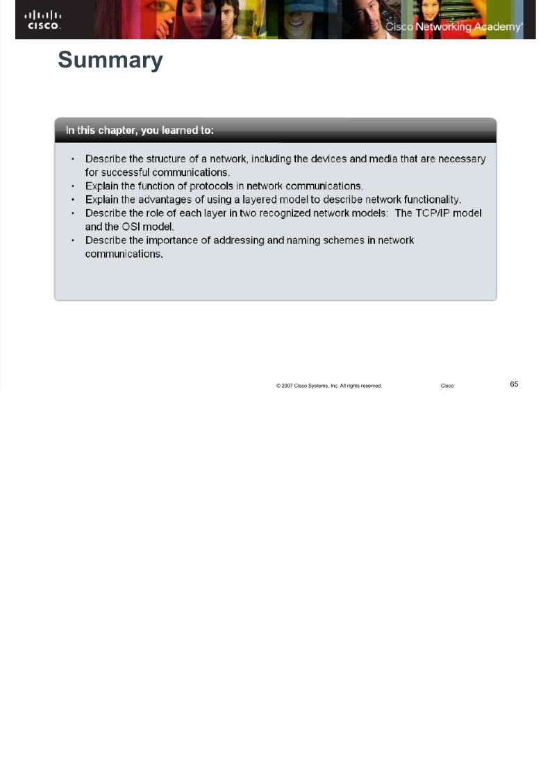
§ Describe the structure of a network, including thedevices and media that are necessary for successfulcommunications.
§ Explain the function of protocols in network
communications.§ Explain the advantages of using a layered model to
describe network functionality.
§ Describe the role of each layer in two recognizednetwork models: The TCP/IP model and the OSImodel.
§ Describe the importance of addressing and namingschemes in network communications.
8/3/2019 Exploration Network Chapter2hkm
http://slidepdf.com/reader/full/exploration-network-chapter2hkm 3/65
3© 2007 Cisco Systems, Inc. All rights reserved. Cisco
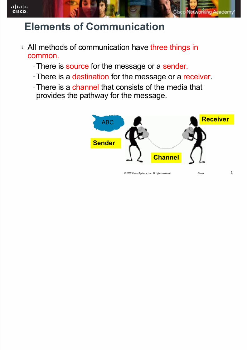
Elements of Communication
§ All methods of communication have three things incommon.
– There is source for the message or a sender. – There is a destination for the message or a receiver . – There is a channel that consists of the media thatprovides the pathway for the message.
ABC
Sender
Channel
Receiver

8/3/2019 Exploration Network Chapter2hkm
http://slidepdf.com/reader/full/exploration-network-chapter2hkm 4/65
4© 2007 Cisco Systems, Inc. All rights reserved. Cisco
Elements of Communication•
Devices communicate in exactly the same way.
8/3/2019 Exploration Network Chapter2hkm
http://slidepdf.com/reader/full/exploration-network-chapter2hkm 5/65
5© 2007 Cisco Systems, Inc. All rights reserved. Cisco
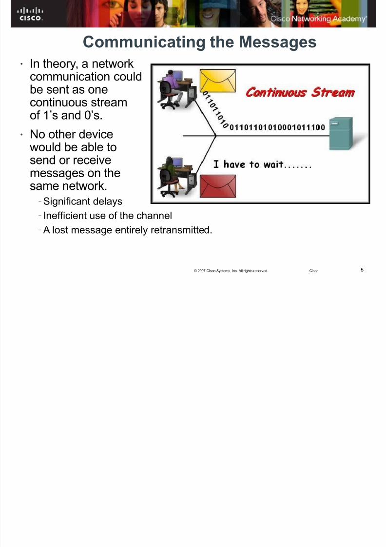
Communicating the Messages
• In theory, a networkcommunication couldbe sent as onecontinuous streamof 1’s and 0’s.
• No other devicewould be able tosend or receivemessages on thesame network.
– Significant delays
– Inefficient use of the channel
– A lost message entirely retransmitted.

8/3/2019 Exploration Network Chapter2hkm
http://slidepdf.com/reader/full/exploration-network-chapter2hkm 6/65
6© 2007 Cisco Systems, Inc. All rights reserved. Cisco
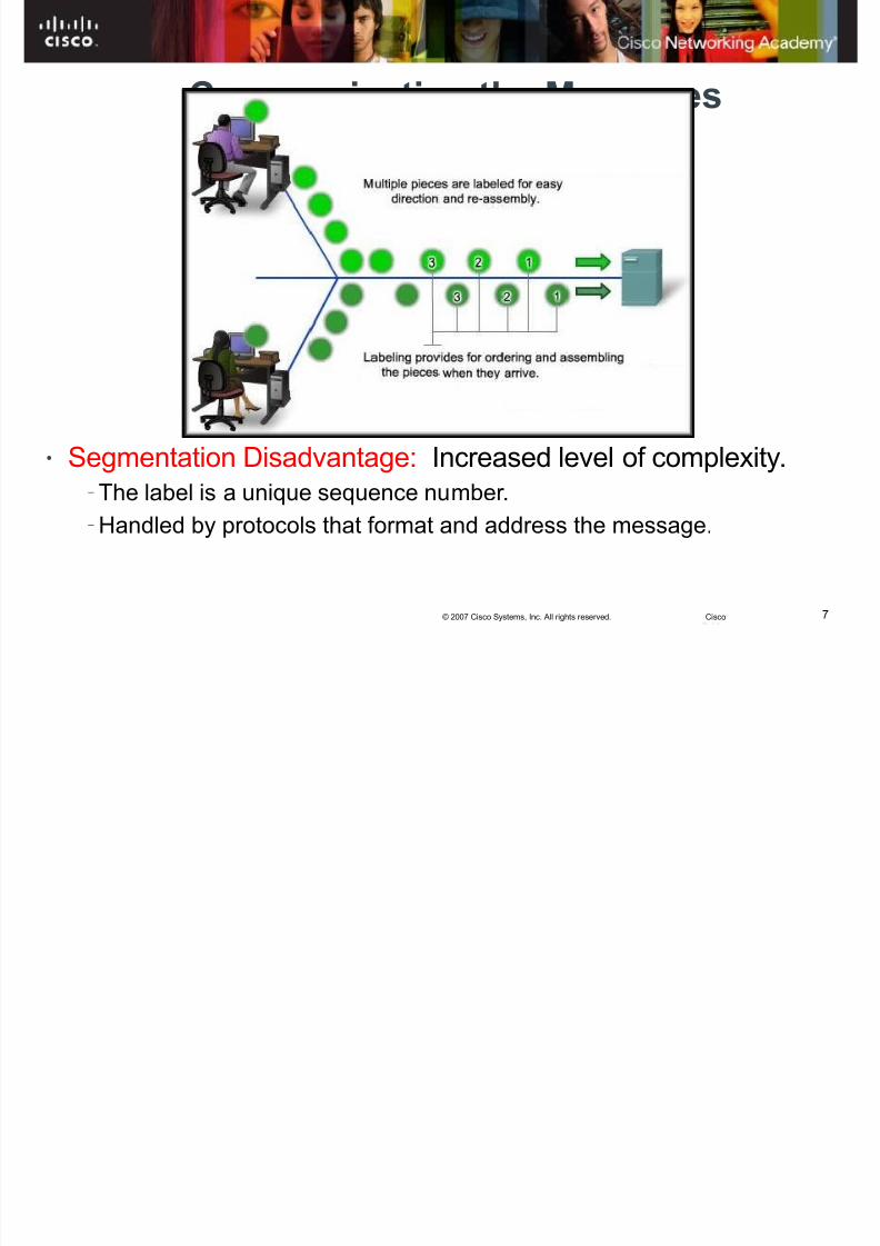
Communicating the Messages• A better approach
is calledSegmentation.
• The data stream isdivided into smaller,
more manageablesegments.
• Segmentation hastwo benefits:
–
Multiplexing:• Different transmissions can be interleaved on the network.
– Reliability
• Pieces can travel different ways, avoiding congestions
• If a piece fails, just resend the failed or missing parts
8/3/2019 Exploration Network Chapter2hkm
http://slidepdf.com/reader/full/exploration-network-chapter2hkm 7/657© 2007 Cisco Systems, Inc. All rights reserved. Cisco
Communicating the Messages
• Segmentation Disadvantage: Increased level of complexity. – The label is a unique sequence number.
– Handled by protocols that format and address the message.

8/3/2019 Exploration Network Chapter2hkm
http://slidepdf.com/reader/full/exploration-network-chapter2hkm 8/658© 2007 Cisco Systems, Inc. All rights reserved. Cisco
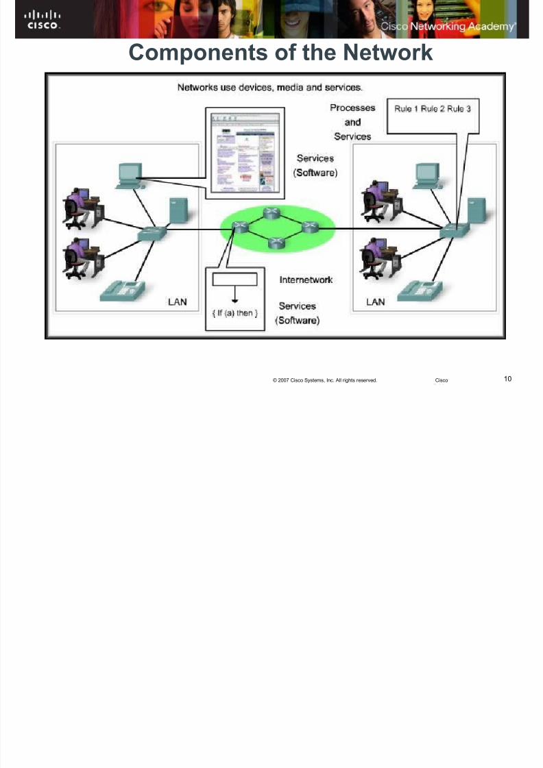
Network Components
Devices (end devices, intermediary devices) – end devices that send and receive messages (e.g.,computers, VoIP phones)
– intermediary devices (e.g., hubs, switches, routers)that move messages among different parts of the
network. – Each type of device plays an important role inmoving messages. Different symbols to representeach device
Media (Cable or wireless)
Services and processes (Software)
HARDWARE
SOFTWARE

8/3/2019 Exploration Network Chapter2hkm
http://slidepdf.com/reader/full/exploration-network-chapter2hkm 9/659© 2007 Cisco Systems, Inc. All rights reserved. Cisco
devices
services
media
8/3/2019 Exploration Network Chapter2hkm
http://slidepdf.com/reader/full/exploration-network-chapter2hkm 10/6510© 2007 Cisco Systems, Inc. All rights reserved. Cisco
Components of the Network
8/3/2019 Exploration Network Chapter2hkm
http://slidepdf.com/reader/full/exploration-network-chapter2hkm 11/6511© 2007 Cisco Systems, Inc. All rights reserved. Cisco
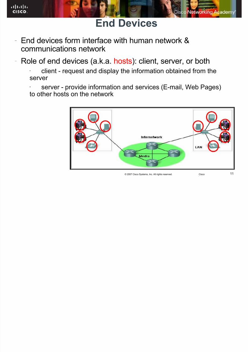
End Devices
– End devices form interface with human network &communications network
– Role of end devices (a.k.a. hosts): client, server, or both• client - request and display the information obtained from theserver
• server - provide information and services (E-mail, Web Pages)to other hosts on the network

8/3/2019 Exploration Network Chapter2hkm
http://slidepdf.com/reader/full/exploration-network-chapter2hkm 12/6512© 2007 Cisco Systems, Inc. All rights reserved. Cisco
Wireless
scanners
Network PrintersNotebooks
Mobile PhonesVOIP Phones
Blackberry
PC
SecurityCameras
Server
8/3/2019 Exploration Network Chapter2hkm
http://slidepdf.com/reader/full/exploration-network-chapter2hkm 13/6513© 2007 Cisco Systems, Inc. All rights reserved. Cisco
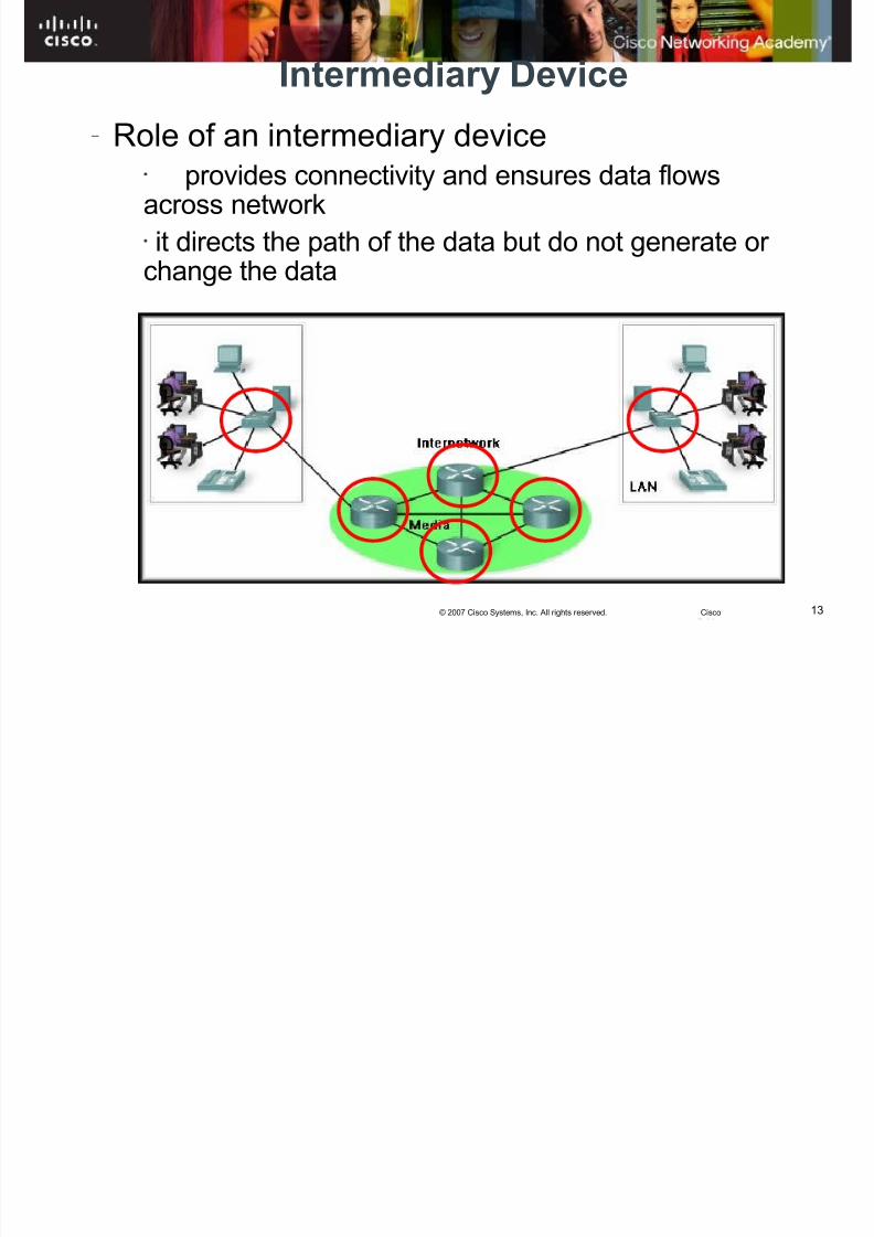
Intermediary Device
–
Role of an intermediary device• provides connectivity and ensures data flowsacross network• it directs the path of the data but do not generate or change the data
8/3/2019 Exploration Network Chapter2hkm
http://slidepdf.com/reader/full/exploration-network-chapter2hkm 14/6514© 2007 Cisco Systems, Inc. All rights reserved. Cisco
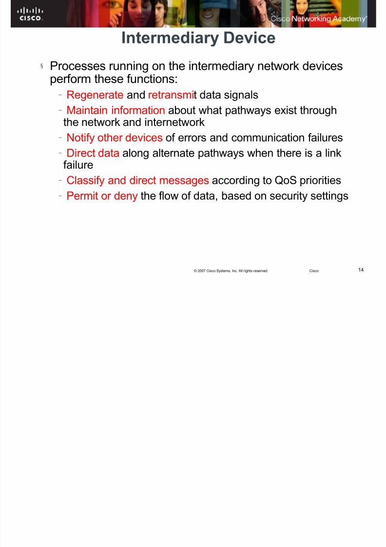
Intermediary Device
§ Processes running on the intermediary network devicesperform these functions:
– Regenerate and retransmit data signals – Maintain information about what pathways exist throughthe network and internetwork
– Notify other devices of errors and communication failures – Direct data along alternate pathways when there is a linkfailure
– Classify and direct messages according to QoS priorities – Permit or deny the flow of data, based on security settings

8/3/2019 Exploration Network Chapter2hkm
http://slidepdf.com/reader/full/exploration-network-chapter2hkm 15/6515© 2007 Cisco Systems, Inc. All rights reserved. Cisco
KC KHOR, MultimediaUniv. Cyberjaya
Intermediary DeviceExamples:
- Network Access Devices (Hubs, switches, and wirelessaccess points)
- Internetworking Devices (routers)
- Communication Servers and Modems
- Security Devices (firewalls)
Cisco PixFirewall
Routers
Modems
Switches
Wireless Access
Point
8/3/2019 Exploration Network Chapter2hkm
http://slidepdf.com/reader/full/exploration-network-chapter2hkm 16/6516© 2007 Cisco Systems, Inc. All rights reserved. Cisco
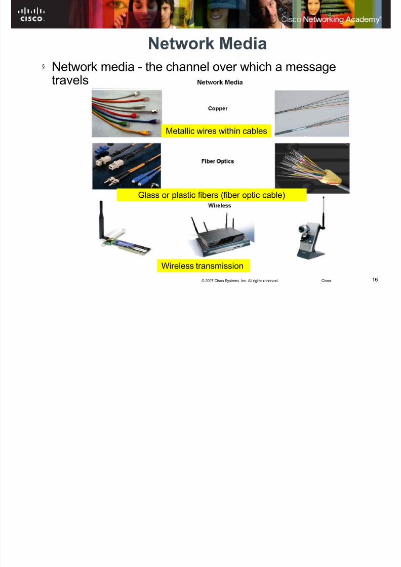
Network Media
§ Network media - the channel over which a messagetravels
Metallic wires within cables
Glass or plastic fibers (fiber optic cable)
Wireless transmission
8/3/2019 Exploration Network Chapter2hkm
http://slidepdf.com/reader/full/exploration-network-chapter2hkm 17/6517© 2007 Cisco Systems, Inc. All rights reserved. Cisco
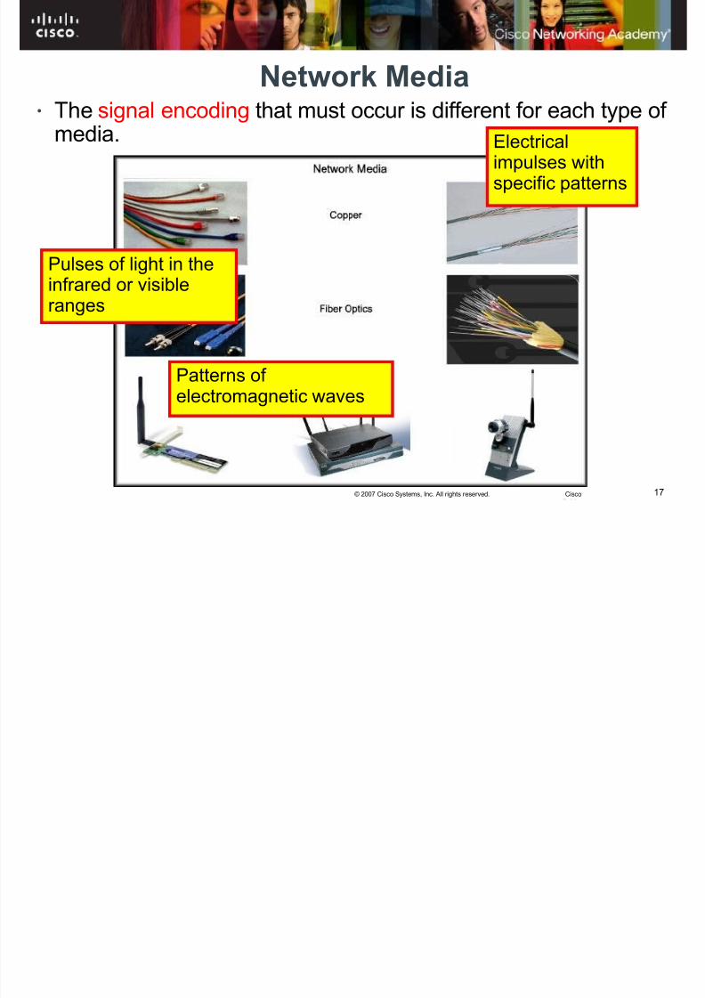
Network Media•
The signal encoding that must occur is different for each type of media. Electricalimpulses withspecific patterns
Pulses of light in theinfrared or visibleranges
Patterns of electromagnetic waves
8/3/2019 Exploration Network Chapter2hkm
http://slidepdf.com/reader/full/exploration-network-chapter2hkm 18/6518© 2007 Cisco Systems, Inc. All rights reserved. Cisco
• Different network media have different features and
benefits.• Not all network media are appropriate for the same
purpose.
§ Criteria for choosing a network media are: –
The distance the media can successfully carry asignal.
– The environment in which the media is to be installed. – The amount of data and the speed at which it must betransmitted.
– The cost of the media and installation
8/3/2019 Exploration Network Chapter2hkm
http://slidepdf.com/reader/full/exploration-network-chapter2hkm 19/6519© 2007 Cisco Systems, Inc. All rights reserved. Cisco
Network Types
§
Networks infrastructures can vary greatly interms of: – The size of the area covered – The number of users connected –
The number and types of services available§ Network types include
– LAN – WAN – Internetworks
8/3/2019 Exploration Network Chapter2hkm
http://slidepdf.com/reader/full/exploration-network-chapter2hkm 20/6520© 2007 Cisco Systems, Inc. All rights reserved. Cisco
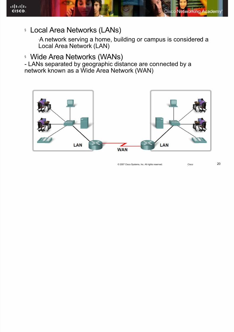
§ Local Area Networks (LANs)-
A network serving a home, building or campus is considered aLocal Area Network (LAN)
§ Wide Area Networks (WANs)- LANs separated by geographic distance are connected by anetwork known as a Wide Area Network (WAN)
8/3/2019 Exploration Network Chapter2hkm
http://slidepdf.com/reader/full/exploration-network-chapter2hkm 21/6521© 2007 Cisco Systems, Inc. All rights reserved. Cisco
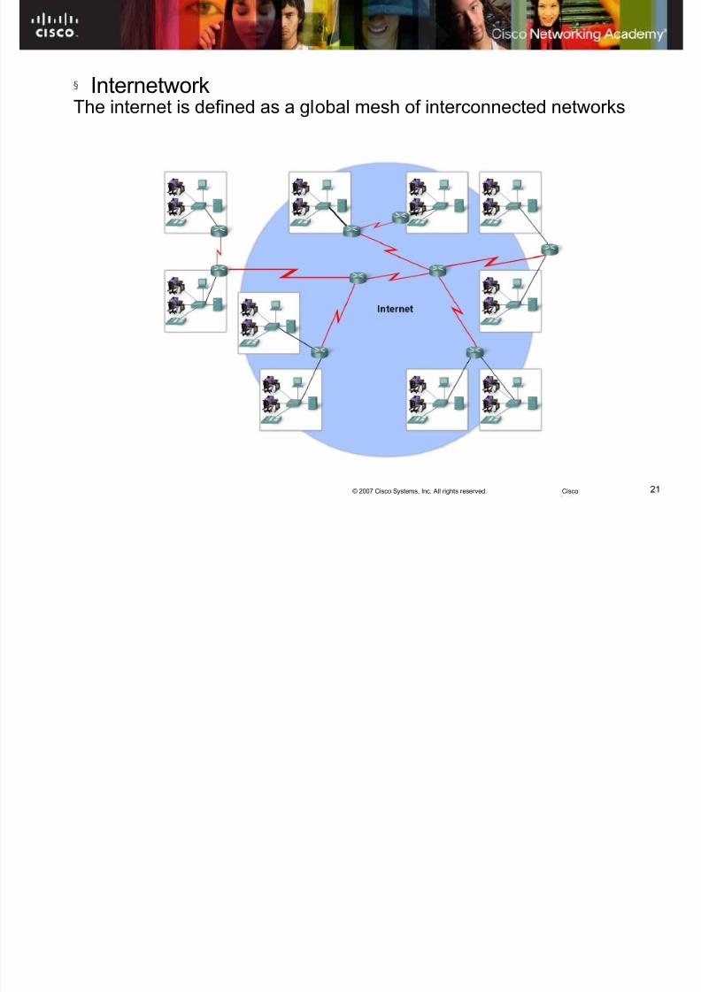
§ InternetworkThe internet is defined as a global mesh of interconnected networks

8/3/2019 Exploration Network Chapter2hkm
http://slidepdf.com/reader/full/exploration-network-chapter2hkm 22/6522© 2007 Cisco Systems, Inc. All rights reserved. Cisco
Network Representations

8/3/2019 Exploration Network Chapter2hkm
http://slidepdf.com/reader/full/exploration-network-chapter2hkm 23/6523© 2007 Cisco Systems, Inc. All rights reserved. Cisco
Network Representations
• Network Interface Card (NIC): – Provides the physical connection to the network at the PC or other host device.
• Physical Port:• A connector or outlet on a networking
device where the media is connected to ahost or other networking device.
8/3/2019 Exploration Network Chapter2hkm
http://slidepdf.com/reader/full/exploration-network-chapter2hkm 24/65
24© 2007 Cisco Systems, Inc. All rights reserved. Cisco
Network Representations
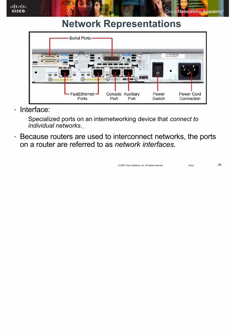
• Interface: –
Specialized ports on an internetworking device that connect toindividual networks.
• Because routers are used to interconnect networks, the portson a router are referred to as network interfaces.
8/3/2019 Exploration Network Chapter2hkm
http://slidepdf.com/reader/full/exploration-network-chapter2hkm 25/65
25© 2007 Cisco Systems, Inc. All rights reserved. Cisco
Rules That Govern Communications•
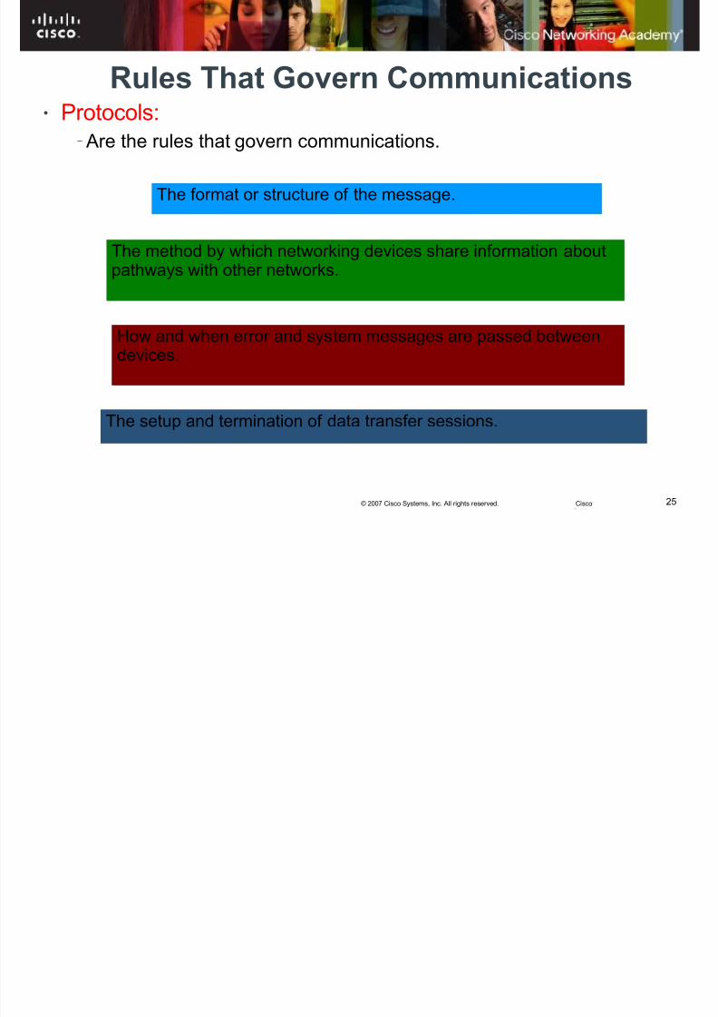
Protocols: – Are the rules that govern communications.
The format or structure of the message.
How and when error and system messages are passed between
devices.
The setup and termination of data transfer sessions.
The method by which networking devices share information aboutpathways with other networks.
8/3/2019 Exploration Network Chapter2hkm
http://slidepdf.com/reader/full/exploration-network-chapter2hkm 26/65
26© 2007 Cisco Systems, Inc. All rights reserved. Cisco
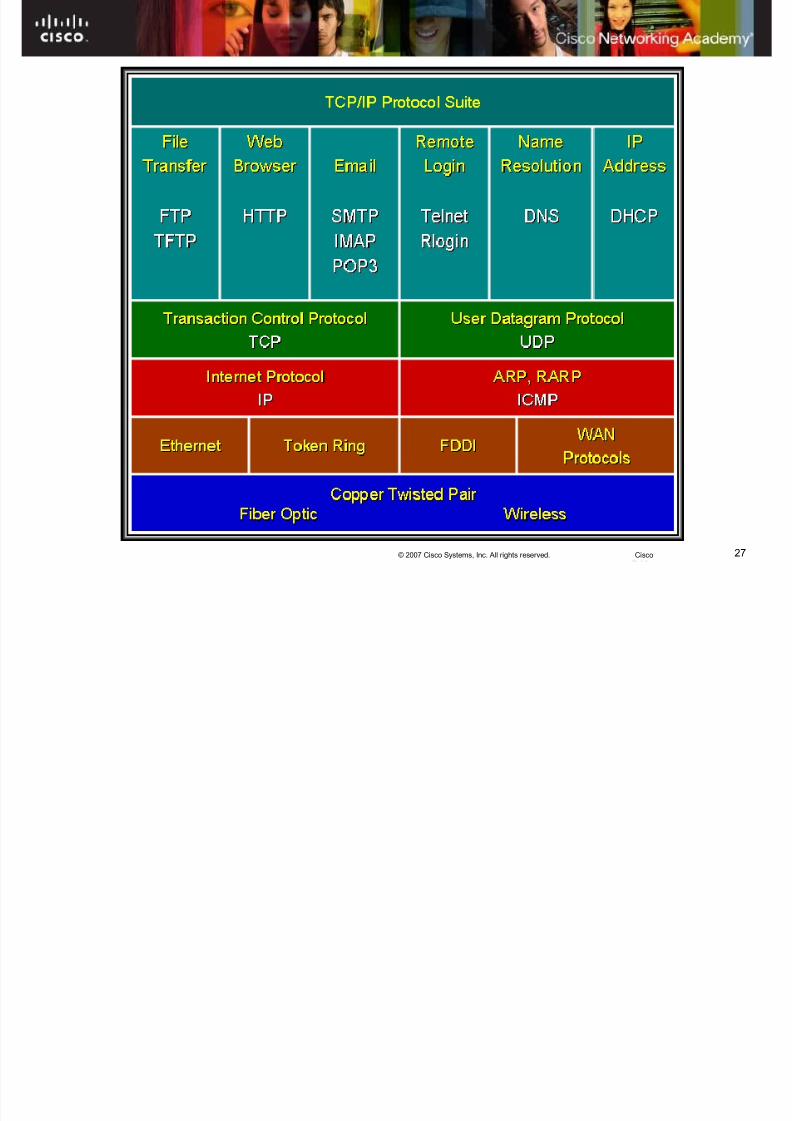
Protocol Suites•
Protocol Suite: – A group of inter-related protocols that are necessary to perform acommunication function.
– Cannot function without a set of standards that network vendors canfollow.
–
Institute of Electrical and Electronics Engineers (IEEE):• Develops standards in telecommunications, information technology
and power generation.
• Examples: 802.3 (Ethernet), 802.11 (WLAN) – Internet Engineering Task Force (IETF)
•
Internet standards, RFCs (Request for Comments)• Example: TCP, IP, HTTP, FTP
8/3/2019 Exploration Network Chapter2hkm
http://slidepdf.com/reader/full/exploration-network-chapter2hkm 27/65
27© 2007 Cisco Systems, Inc. All rights reserved. Cisco
Protocol Suites
8/3/2019 Exploration Network Chapter2hkm
http://slidepdf.com/reader/full/exploration-network-chapter2hkm 28/65
28© 2007 Cisco Systems, Inc. All rights reserved. Cisco
Function of Protocol in Network Communication
§ The protocols are viewed as a layered hierarchy, witheach higher level service depending on the functionalitydefined by the protocols shown in the lower levels.
§ The lower layers of the stack are concerned with –
moving data over the network and – providing services to the upper layers
§ the upper layers are focused on – the content of the message being sent and
– the user interface.

8/3/2019 Exploration Network Chapter2hkm
http://slidepdf.com/reader/full/exploration-network-chapter2hkm 29/65
29© 2007 Cisco Systems, Inc. All rights reserved. Cisco
Function of Protocol in Network Communication
Layer 1
Layer 2
Layer 3
8/3/2019 Exploration Network Chapter2hkm
http://slidepdf.com/reader/full/exploration-network-chapter2hkm 30/65
30© 2007 Cisco Systems, Inc. All rights reserved. Cisco
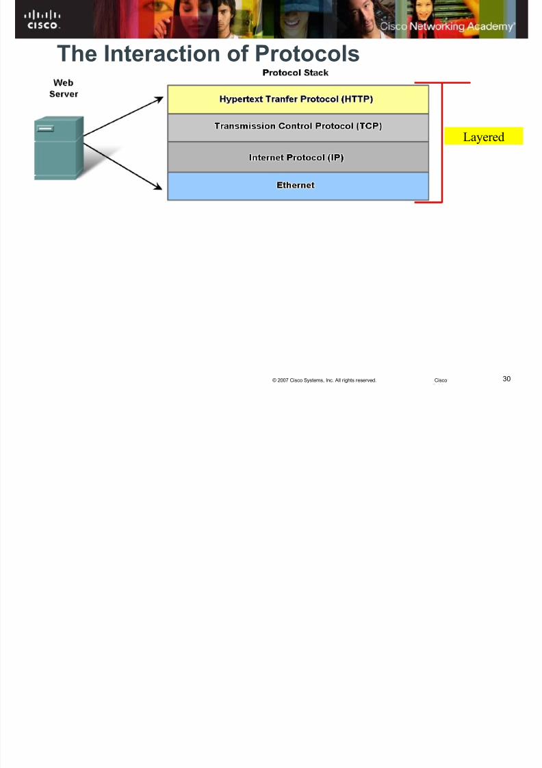
Layered
The Interaction of Protocols
8/3/2019 Exploration Network Chapter2hkm
http://slidepdf.com/reader/full/exploration-network-chapter2hkm 31/65
31© 2007 Cisco Systems, Inc. All rights reserved. Cisco
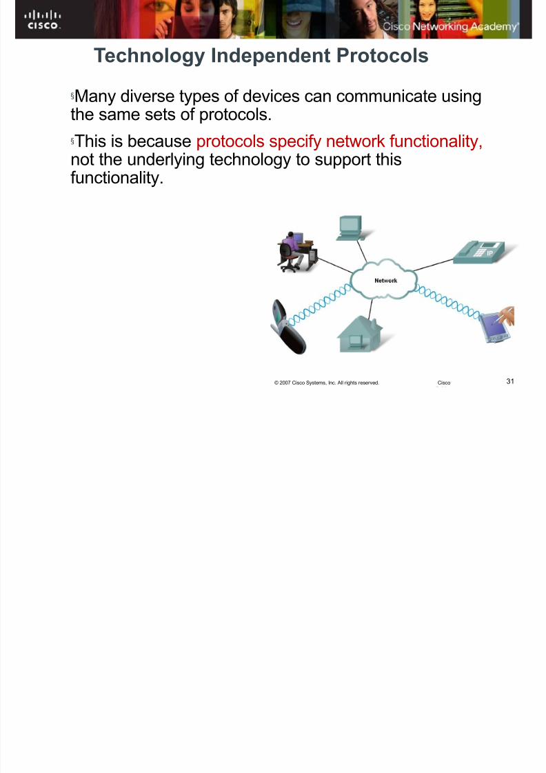
Technology Independent Protocols
§Many diverse types of devices can communicate usingthe same sets of protocols.
§This is because protocols specify network functionality, not the underlying technology to support this
functionality.

8/3/2019 Exploration Network Chapter2hkm
http://slidepdf.com/reader/full/exploration-network-chapter2hkm 32/65
32© 2007 Cisco Systems, Inc. All rights reserved. Cisco
Layered Models :: TCP/IP and OSI
§ A layered model – depicts the operation of the protocols occurring withineach layer,
– as well as the interaction with the layers above andbelow it.
§ Benefits of using a layered modelü assists in protocol designü fosters competitionü changes in one layer do not affect other layersü provides a common language
8/3/2019 Exploration Network Chapter2hkm
http://slidepdf.com/reader/full/exploration-network-chapter2hkm 33/65
33© 2007 Cisco Systems, Inc. All rights reserved. Cisco
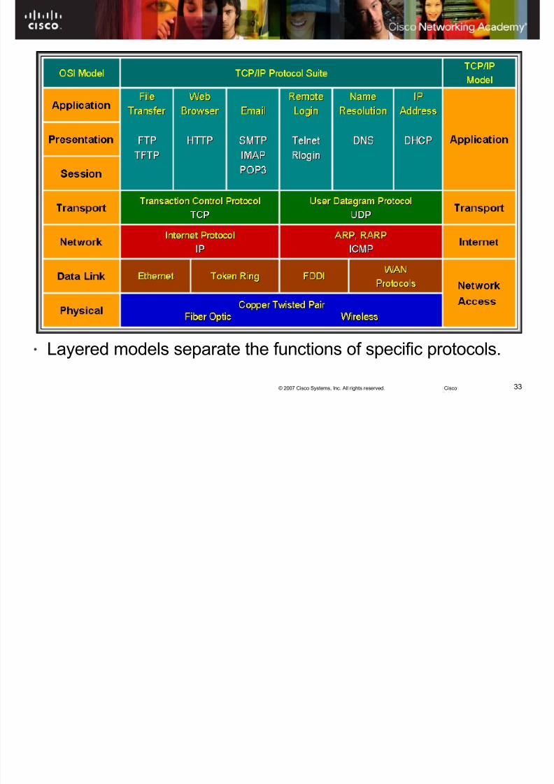
Layered Models
• Layered models separate the functions of specific protocols.
8/3/2019 Exploration Network Chapter2hkm
http://slidepdf.com/reader/full/exploration-network-chapter2hkm 34/65
34© 2007 Cisco Systems, Inc. All rights reserved. Cisco
Protocol & Reference Model
§ Two basic types of networking models:: protocol models andreference models.
A protocol model provides amodel that closely matches thestructure of a particular protocol suite.
The hierarchical set of related
protocols in a suite typicallyrepresents all the functionalityrequired to interface thehuman network with the datanetwork. Ex: TCP/IP model
§ A reference model provides acommon reference for maintaining consistency withinall types of network protocolsand services.
§
The primary purpose of areference model is to aid inclearer understanding of thefunctions and process involved.Ex: OSI model

8/3/2019 Exploration Network Chapter2hkm
http://slidepdf.com/reader/full/exploration-network-chapter2hkm 35/65
35© 2007 Cisco Systems, Inc. All rights reserved. Cisco
Protocol and Reference Models
A protocol model provides amodel that closely matches thestructure of a particular protocolsuite.
The hierarchical set of relatedprotocols in a suite typicallyrepresents all the functionalityrequired to interface the humannetwork with the data network.
8/3/2019 Exploration Network Chapter2hkm
http://slidepdf.com/reader/full/exploration-network-chapter2hkm 36/65
36© 2007 Cisco Systems, Inc. All rights reserved. Cisco
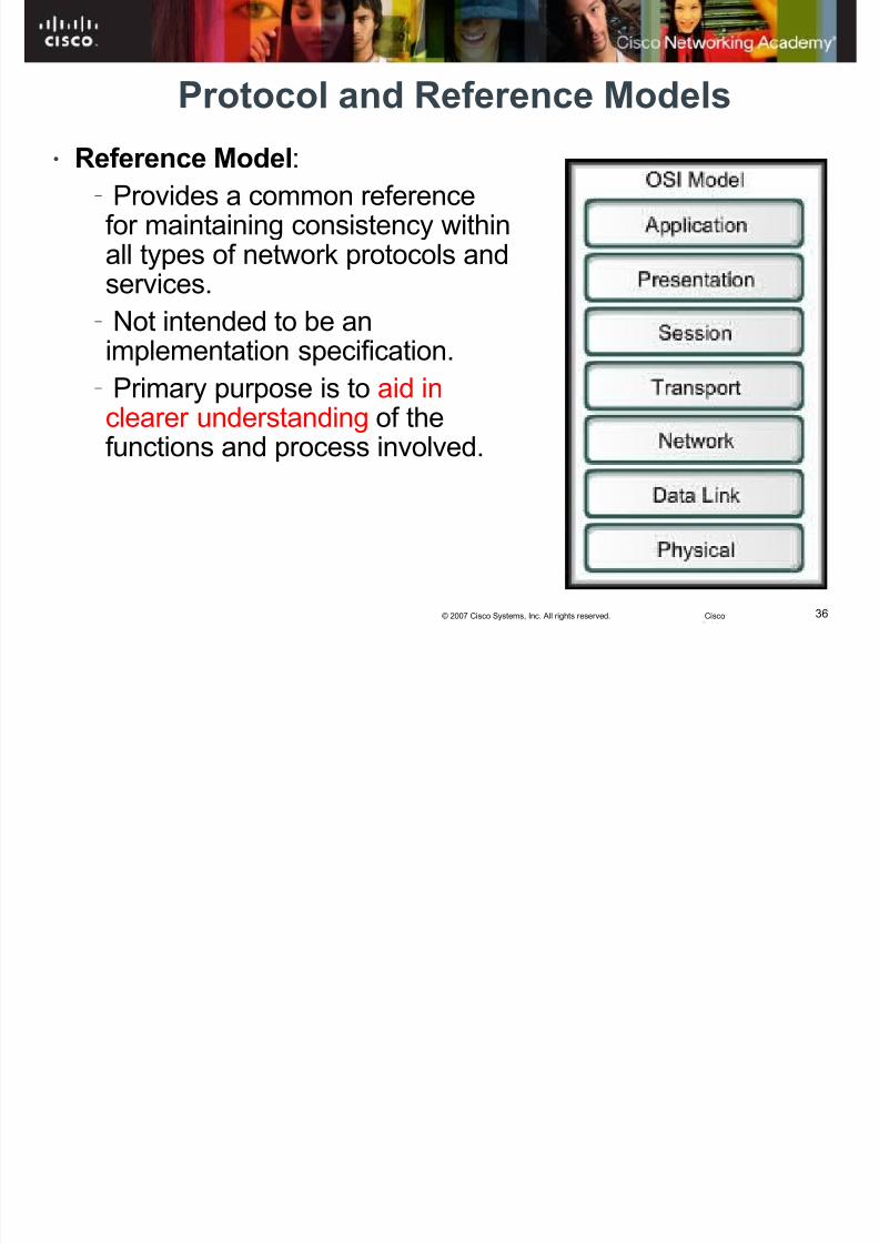
Protocol and Reference Models
• Reference Model: – Provides a common referencefor maintaining consistency withinall types of network protocols and
services. – Not intended to be animplementation specification.
– Primary purpose is to aid inclearer understanding of the
functions and process involved.

8/3/2019 Exploration Network Chapter2hkm
http://slidepdf.com/reader/full/exploration-network-chapter2hkm 37/65
37© 2007 Cisco Systems, Inc. All rights reserved. Cisco
Protocol & Reference Model
A protocol model
provides a model thatclosely matches thestructure of aparticular protocolsuite.
A reference model
provides acommon referencefor maintainingconsistency withinall types of
network protocolsand services.
OSITCP/IP
8/3/2019 Exploration Network Chapter2hkm
http://slidepdf.com/reader/full/exploration-network-chapter2hkm 38/65
38© 2007 Cisco Systems, Inc. All rights reserved. Cisco
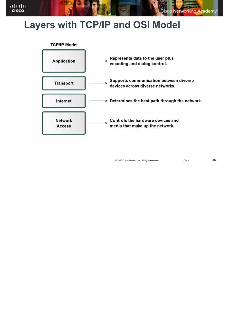
Layers with TCP/IP and OSI Model
8/3/2019 Exploration Network Chapter2hkm
http://slidepdf.com/reader/full/exploration-network-chapter2hkm 39/65
39© 2007 Cisco Systems, Inc. All rights reserved. Cisco
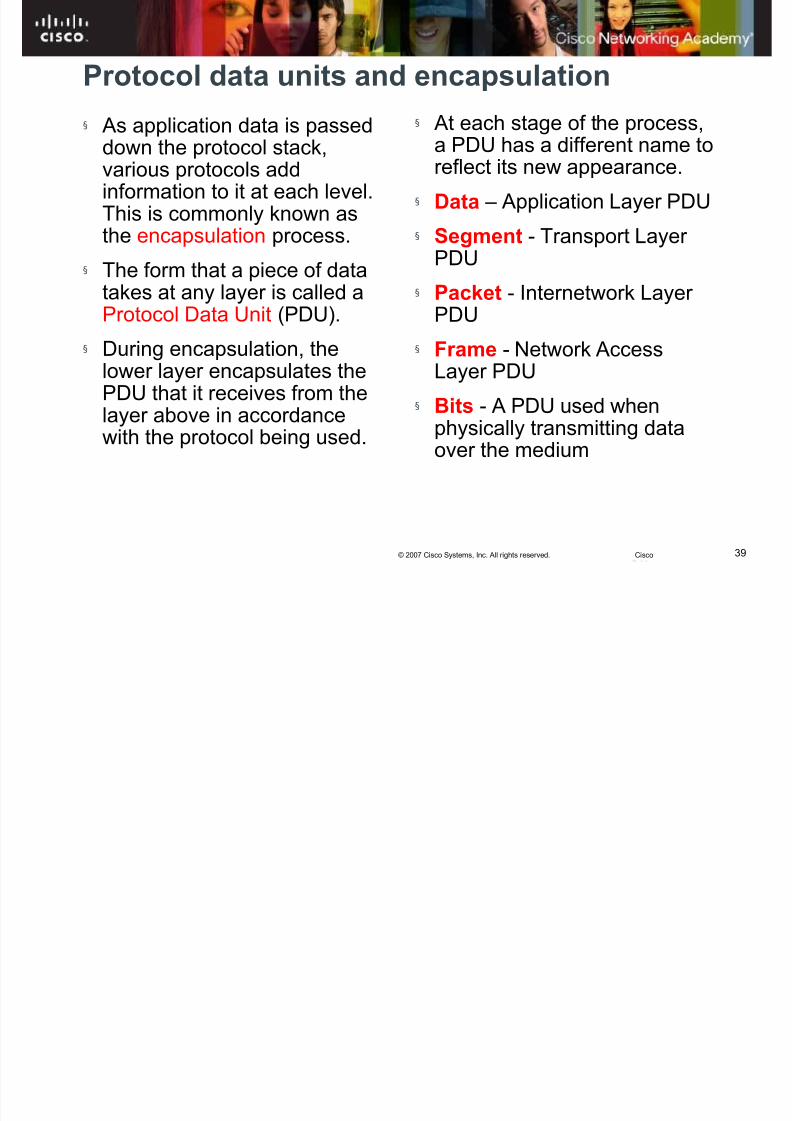
Protocol data units and encapsulation
§ As application data is passeddown the protocol stack,various protocols addinformation to it at each level.This is commonly known asthe encapsulation process.
§ The form that a piece of datatakes at any layer is called aProtocol Data Unit (PDU).
§ During encapsulation, thelower layer encapsulates the
PDU that it receives from thelayer above in accordancewith the protocol being used.
§ At each stage of the process,a PDU has a different name toreflect its new appearance.
§ Data – Application Layer PDU
§ Segment - Transport Layer
PDU§ Packet - Internetwork Layer
PDU
§ Frame - Network AccessLayer PDU
§ Bits - A PDU used whenphysically transmitting dataover the medium

8/3/2019 Exploration Network Chapter2hkm
http://slidepdf.com/reader/full/exploration-network-chapter2hkm 40/65
40© 2007 Cisco Systems, Inc. All rights reserved. Cisco
The Communication Process
Segment andEncapsulate
Generate onto the media
Create Data
Transport through the segment
Pass data toapplication
Receive fromthe media
Decapsulate andReassemble

8/3/2019 Exploration Network Chapter2hkm
http://slidepdf.com/reader/full/exploration-network-chapter2hkm 41/65
41© 2007 Cisco Systems, Inc. All rights reserved. Cisco

8/3/2019 Exploration Network Chapter2hkm
http://slidepdf.com/reader/full/exploration-network-chapter2hkm 42/65
42© 2007 Cisco Systems, Inc. All rights reserved. Cisco
Segmentation and Encapsulation
Header
Header Data
Header Trailer
Email Message
Data Data Data
Data
Data
001010011101100101000001111101010001010
1

8/3/2019 Exploration Network Chapter2hkm
http://slidepdf.com/reader/full/exploration-network-chapter2hkm 43/65
43© 2007 Cisco Systems, Inc. All rights reserved. Cisco
Decapsulation and Reassembly
Header
Header
Header Trailer
Email Message
Data Data Data
Data
Data
Data
Data
001010011101100101000001111101010001010
1
8/3/2019 Exploration Network Chapter2hkm
http://slidepdf.com/reader/full/exploration-network-chapter2hkm 44/65
44© 2007 Cisco Systems, Inc. All rights reserved. Cisco
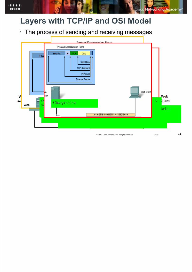
Layers with TCP/IP and OSI Model§
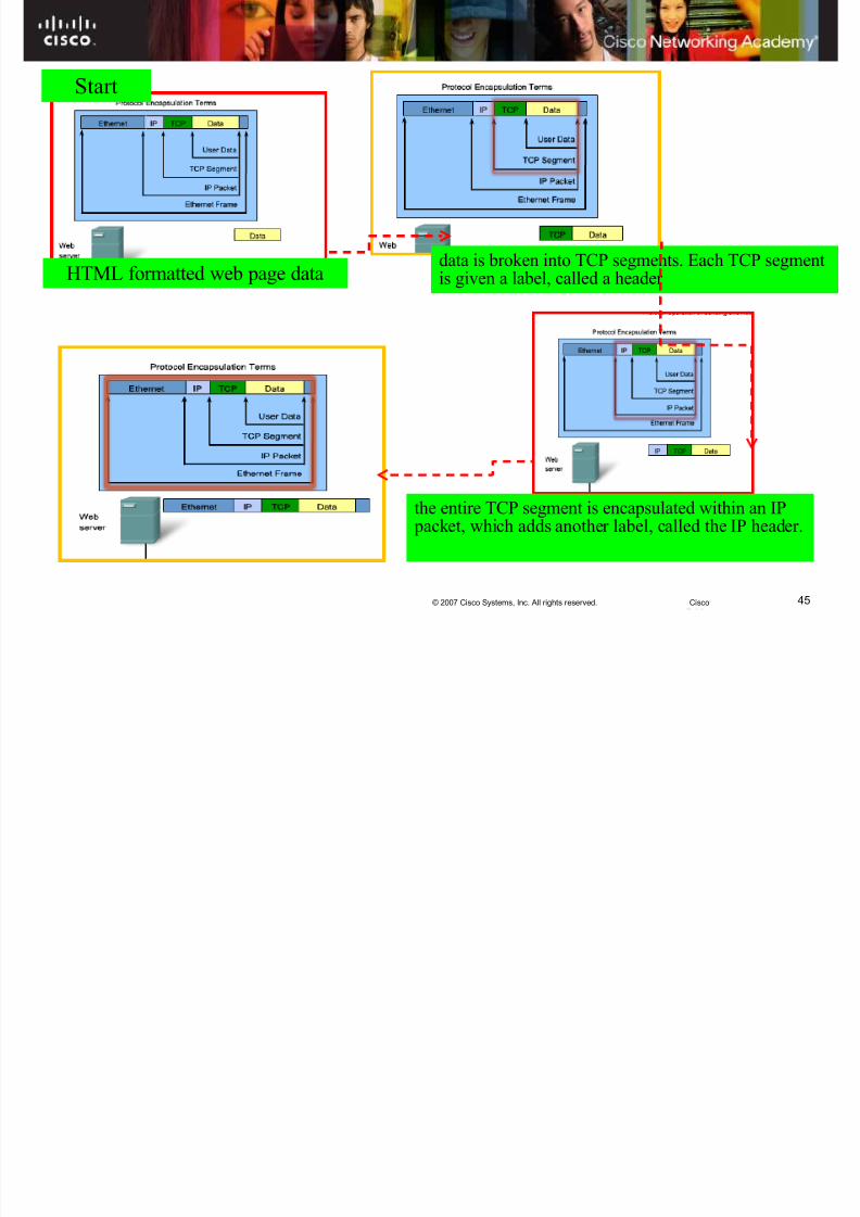
The process of sending and receiving messagesStart
HTML formatted web page data
data is broken into TCP segments. Each TCP segment is given a label, called aheader
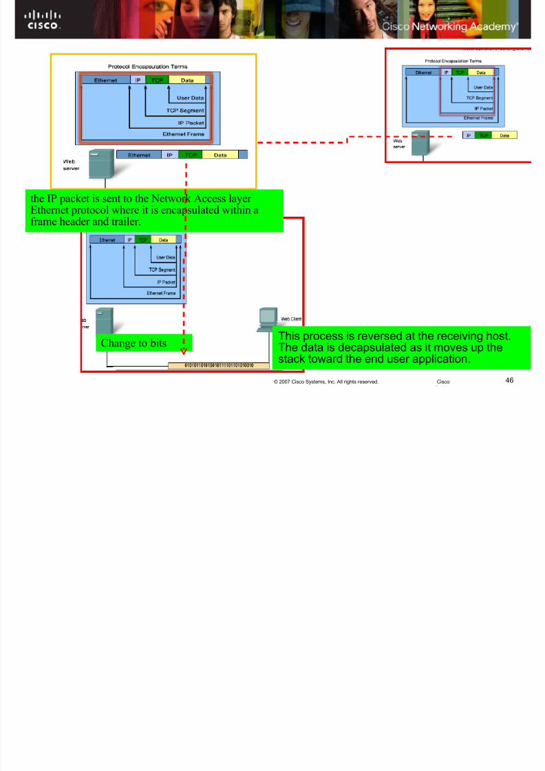
the entire TCP segment is encapsulated within an IP packet, which addsanother label, called the IP header.the IP packet is sent to the Network Access layer Ethernet protocolwhere it is encapsulated within a frame header and trailer.
Change to bits
8/3/2019 Exploration Network Chapter2hkm
http://slidepdf.com/reader/full/exploration-network-chapter2hkm 45/65
45© 2007 Cisco Systems, Inc. All rights reserved. Cisco
data is broken into TCP segments. Each TCP segmentis given a label, called a header
Start
HTML formatted web page data
the entire TCP segment is encapsulated within an IP packet, which adds another label, called the IP header.
8/3/2019 Exploration Network Chapter2hkm
http://slidepdf.com/reader/full/exploration-network-chapter2hkm 46/65
46© 2007 Cisco Systems, Inc. All rights reserved. Cisco
Change to bits
the IP packet is sent to the Network Access layer Ethernet protocol where it is encapsulated within aframe header and trailer.
This process is reversed at the receiving host.The data is decapsulated as it moves up thestack toward the end user application.

8/3/2019 Exploration Network Chapter2hkm
http://slidepdf.com/reader/full/exploration-network-chapter2hkm 47/65
47© 2007 Cisco Systems, Inc. All rights reserved. Cisco
OSI Model• Breaks network communication into
smaller, more manageable parts. – Makes learning it easier tounderstand.
– Prevents changes in one layer fromaffecting other layers.
• Standardizes network componentsto allow multiple vendor developmentand support.
• Allows different types of networkhardware and software to communicatewith each other.
• It is a descriptive scheme.
8/3/2019 Exploration Network Chapter2hkm
http://slidepdf.com/reader/full/exploration-network-chapter2hkm 48/65
48© 2007 Cisco Systems, Inc. All rights reserved. Cisco
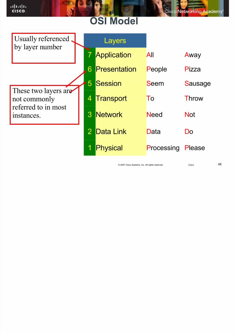
OSI Model
Layers
7 Application All Away
6 Presentation People Pizza
5 Session Seem Sausage
4 Transport To Throw
3 Network Need Not
2 Data Link Data Do
1 Physical Processing Please
Usually referenced by layer number
These two layers arenot commonlyreferred to in mostinstances.
8/3/2019 Exploration Network Chapter2hkm
http://slidepdf.com/reader/full/exploration-network-chapter2hkm 49/65
49© 2007 Cisco Systems, Inc. All rights reserved. Cisco
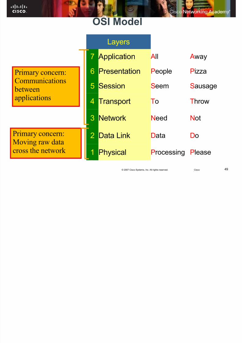
OSI Model
Layers
7 Application All Away
6 Presentation People Pizza
5 Session Seem Sausage
4 Transport To Throw
3 Network Need Not
2 Data Link Data Do
1 Physical Processing Please
Primary concern:
Communications betweenapplications
Primary concern:Moving raw datacross the network
8/3/2019 Exploration Network Chapter2hkm
http://slidepdf.com/reader/full/exploration-network-chapter2hkm 50/65
50© 2007 Cisco Systems, Inc. All rights reserved. Cisco
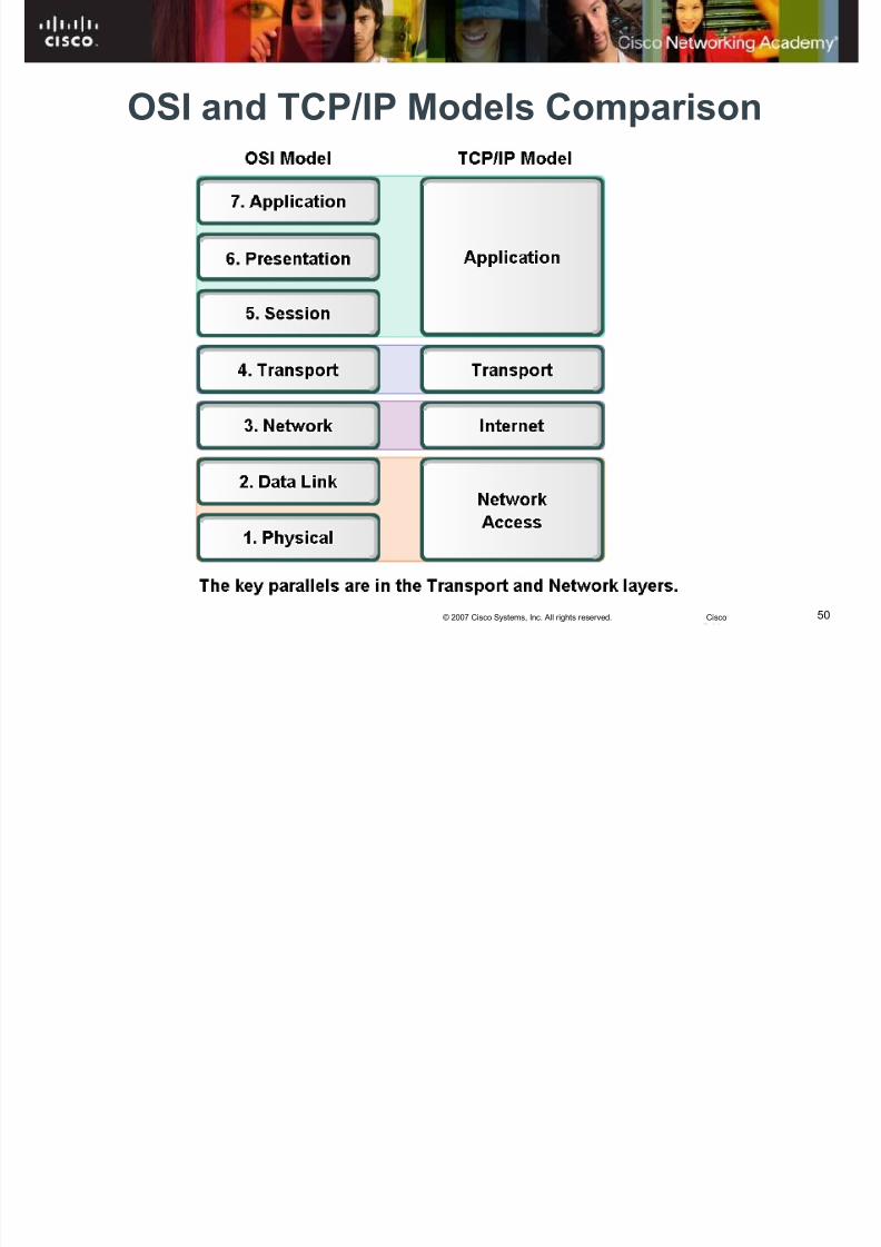
OSI and TCP/IP Models Comparison

8/3/2019 Exploration Network Chapter2hkm
http://slidepdf.com/reader/full/exploration-network-chapter2hkm 51/65
51© 2007 Cisco Systems, Inc. All rights reserved. Cisco
OSI Model
OSI Model Layer Addressing
ApplicationEncoded Application Data
(Usually referred to as the Upper Layers)
Presentation
Session
Transport Source and Destination: Process Address
Network Source and Destination: Logical Network Address
Data Link Source and Destination: Device Physical Address
Physical Timing and Synchronization Bits
8/3/2019 Exploration Network Chapter2hkm
http://slidepdf.com/reader/full/exploration-network-chapter2hkm 52/65
52© 2007 Cisco Systems, Inc. All rights reserved. Cisco
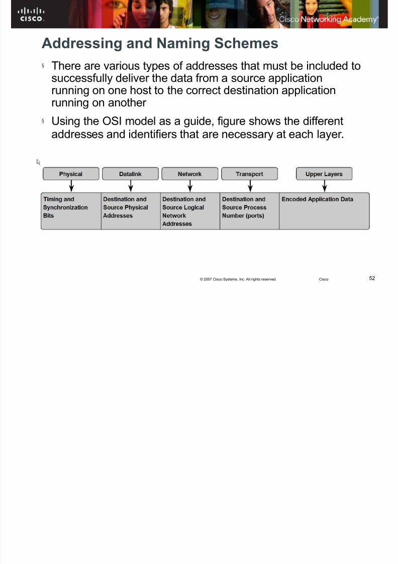
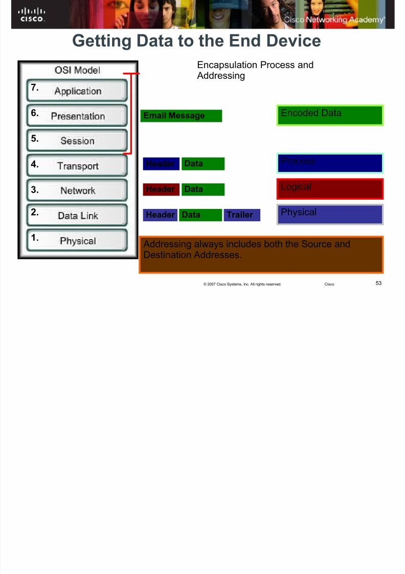
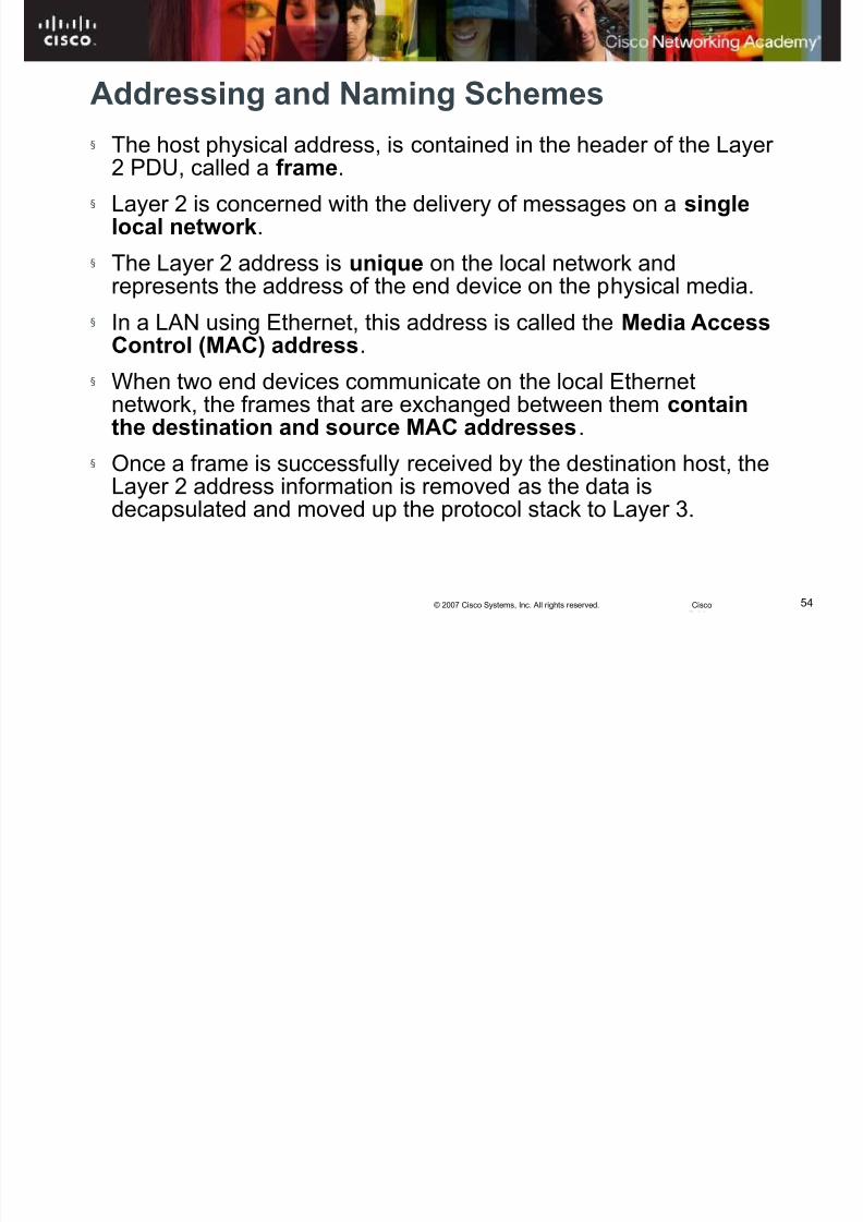
Addressing and Naming Schemes
§
There are various types of addresses that must be included tosuccessfully deliver the data from a source applicationrunning on one host to the correct destination applicationrunning on another
§ Using the OSI model as a guide, figure shows the different
addresses and identifiers that are necessary at each layer .
8/3/2019 Exploration Network Chapter2hkm
http://slidepdf.com/reader/full/exploration-network-chapter2hkm 53/65
53© 2007 Cisco Systems, Inc. All rights reserved. Cisco
Getting Data to the End Device
Header
Header
Header Trailer
Email Message
Data
Data
Data
Encoded Data
Process
Logical
Physical
Encapsulation Process and Addressing
1.
2.
3.
4.
5.
6.
7.
Addressing always includes both the Source andDestination Addresses.
8/3/2019 Exploration Network Chapter2hkm
http://slidepdf.com/reader/full/exploration-network-chapter2hkm 54/65
54© 2007 Cisco Systems, Inc. All rights reserved. Cisco
Addressing and Naming Schemes
§
The host physical address, is contained in the header of the Layer 2 PDU, called a frame.
§ Layer 2 is concerned with the delivery of messages on a singlelocal network.
§ The Layer 2 address is unique on the local network and
represents the address of the end device on the physical media.§ In a LAN using Ethernet, this address is called the Media Access
Control (MAC) address.
§ When two end devices communicate on the local Ethernetnetwork, the frames that are exchanged between them containthe destination and source MAC addresses.
§ Once a frame is successfully received by the destination host, theLayer 2 address information is removed as the data isdecapsulated and moved up the protocol stack to Layer 3.
8/3/2019 Exploration Network Chapter2hkm
http://slidepdf.com/reader/full/exploration-network-chapter2hkm 55/65
55© 2007 Cisco Systems, Inc. All rights reserved. Cisco
Getting the Data Through the Internetwork
Layer 3 protocols are primarily designed to move datafrom one local network to another local network withinan internetwork.
Layer 3 addresses must include identifiers that enableintermediary network devices to locate hosts ondifferent networks
At the boundary of each local network, an intermediarynetwork device, usually a router , decapsulates theframe to read the destination host address contained inthe header of the packet, the Layer 3 PDU
Routers use the network identifier portion of thisaddress to determine which path to use to reach thedestination host.
8/3/2019 Exploration Network Chapter2hkm
http://slidepdf.com/reader/full/exploration-network-chapter2hkm 56/65
56© 2007 Cisco Systems, Inc. All rights reserved. Cisco
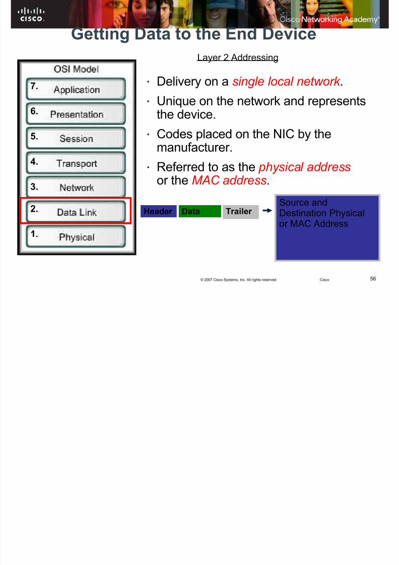
Getting Data to the End Device
1.
2.
3.
4.
5.
6.
7.
Layer 2 Addressing
• Delivery on a single local network .
• Unique on the network and representsthe device.
•
Codes placed on the NIC by themanufacturer.
• Referred to as the physical addressor the MAC address.
Header Trailer Data Source andDestination Physicalor MAC Address

8/3/2019 Exploration Network Chapter2hkm
http://slidepdf.com/reader/full/exploration-network-chapter2hkm 57/65
57© 2007 Cisco Systems, Inc. All rights reserved. Cisco
Getting Data to the End Device
DestinationMAC
Address
SourceMAC
AddressData
Layer 2 Header
8/3/2019 Exploration Network Chapter2hkm
http://slidepdf.com/reader/full/exploration-network-chapter2hkm 58/65
58© 2007 Cisco Systems, Inc. All rights reserved. Cisco
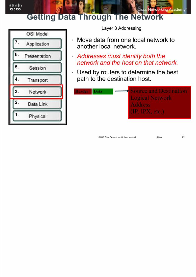
Getting Data Through The Network
Header Data Source and Destination
Logical Network Address(IP, IPX, etc.)
1.
2.
3.
4.
5.
6.
7.
Layer 3 Addressing
• Move data from one local network toanother local network.
• Addresses must identify both thenetwork and the host on that network.
• Used by routers to determine the bestpath to the destination host.
8/3/2019 Exploration Network Chapter2hkm
http://slidepdf.com/reader/full/exploration-network-chapter2hkm 59/65
59© 2007 Cisco Systems, Inc. All rights reserved. Cisco
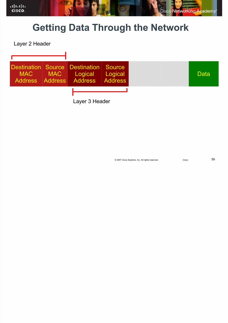
Getting Data Through the Network
DestinationMAC
Address
SourceMAC
Address
DestinationLogical
Address
SourceLogical
AddressData
Layer 2 Header
Layer 3 Header
8/3/2019 Exploration Network Chapter2hkm
http://slidepdf.com/reader/full/exploration-network-chapter2hkm 60/65
60© 2007 Cisco Systems, Inc. All rights reserved. Cisco
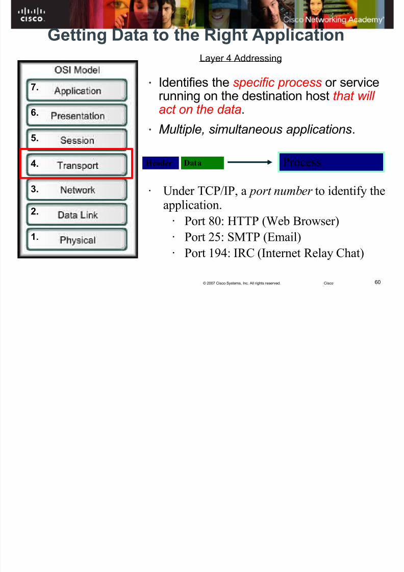
Getting Data to the Right Application
1.
2.
3.
4.
5.
6.
7.
Layer 4 Addressing
• Identifies the specific process or servicerunning on the destination host that will act on the data.
• Multiple, simultaneous applications.
Header Data Process
• Under TCP/IP, a port number to identify the
application.• Port 80: HTTP (Web Browser)• Port 25: SMTP (Email)• Port 194: IRC (Internet Relay Chat)

8/3/2019 Exploration Network Chapter2hkm
http://slidepdf.com/reader/full/exploration-network-chapter2hkm 61/65
61© 2007 Cisco Systems, Inc. All rights reserved. Cisco
Getting Data to the Right Application
DestinationMAC
Address
SourceMAC
Address
DestinationLogical
Address
SourceLogical
Address
DestinationProcess
Address
SourceProcess
Address
Data
Layer 2 Header
Layer 3 Header
Layer 4 Header

8/3/2019 Exploration Network Chapter2hkm
http://slidepdf.com/reader/full/exploration-network-chapter2hkm 62/65
62© 2007 Cisco Systems, Inc. All rights reserved. Cisco
Putting It All Together
DestinationMAC
Address
SourceMAC
Address
DestinationLogical
Address
SourceLogical
Address
DestinationProcess
Address
SourceProcess
AddressData
LogicalMAC
Port
MAC

8/3/2019 Exploration Network Chapter2hkm
http://slidepdf.com/reader/full/exploration-network-chapter2hkm 63/65
63© 2007 Cisco Systems, Inc. All rights reserved. Cisco
Comparing the OSI and TCP/IP Models
OSI Model Layer FunctionProtocol
Data UnitDevice
TCP/IP
Model
7 Application User Functionality
Character Application6 Presentation Character Representation
5 Session Manage Data Exchange
4 TransportServices to segment, transfer andreassemble the data
Segment Transport
3 NetworkNetwork addressing and best pathdetermination
Packet Router Internet
2 Data LinkMethods for reliable frame exchangeover a common media
Frame SwitchNetwork Access
1 PhysicalDescribe physical characteristics totransmit bits over a common media
Bit Hub

8/3/2019 Exploration Network Chapter2hkm
http://slidepdf.com/reader/full/exploration-network-chapter2hkm 64/65
64© 2007 Cisco Systems, Inc. All rights reserved. Cisco
Too much info?
8/3/2019 Exploration Network Chapter2hkm
http://slidepdf.com/reader/full/exploration-network-chapter2hkm 65/65
Summary