Expert Dual Discrete Outputs - magtrol.com in USA 01/04 P/N 64154 rev. D D10 Expert™– Dual...
12
Printed in USA 01/04 P/N 64154 rev. D D10 Expert ™ – Dual Discrete Outputs Advanced sensor for use with plastic fiber optics Models Features • Easy-to-set automatic Expert-style TEACH options* including static, dynamic, and single-point programming plus manual adjustment for fine-tuning • 16-bit microcontroller and 12-bit Analog-to-Digital converter for high-performance, low-contrast sensing • Easy-to-read 4-digit display for TEACH and signal strength readout, plus indicators for a continuous readout of operating status (user configurable) • Two discrete outputs, PNP or NPN • Four-mode power and speed selection with automatic cross-talk avoidance circuitry • Selectable OFF-delay options • Gate input wire can be used to selectively inhibit sensor outputs from switching • Models available with visible red (680 nm) or visible green (525 nm) sensing beam • Models available with 2 m or 9 m (6.5' or 30') cable or integral Pico-style quick-disconnect • Sleek, ultra-slim 10 mm housing, mounts to a standard 35 mm DIN rail * U.S. Patent #5,808,296 * 9 m (30') cables are available by adding suffix “W/30” to the model number of any cabled sensor (e.g., D10DNFP W/30). A model with a QD connector requires a mating cable (see page 12). WARNING . . . Not To Be Used for Personnel Protection Never use these products as sensing devices for personnel protection. Doing so could lead to serious injury or death. These sensors do NOT include the self-checking redundant circuitry necessary to allow their use in personnel safety applications. A sensor failure or malfunction can cause either an energized or de-energized sensor output condition. Consult your current Banner Safety Products catalog for safety products which meet OSHA, ANSI and IEC standards for personnel protection. ! Models Cables* Discrete Outputs Red Beam Green Beam D10DNFP D10DNFPG 2 m (6.5') Cable NPN D10DNFPQ D10DNFPGQ 6-pin Pico-style QD D10DPFP D10DPFPG 2 m (6.5') Cable PNP D10DPFPQ D10DPFPGQ 6-pin Pico-style QD
Transcript of Expert Dual Discrete Outputs - magtrol.com in USA 01/04 P/N 64154 rev. D D10 Expert™– Dual...

Printed in USA 01/04 P/N 64154 rev. D
D10 Expert™– Dual Discrete OutputsAdvanced sensor for use with plastic fiber optics
Models
Features
• Easy-to-set automatic Expert-style TEACH options* including static, dynamic, and single-point programming plus manual adjustment for fine-tuning
• 16-bit microcontroller and 12-bit Analog-to-Digital converter for high-performance, low-contrast sensing
• Easy-to-read 4-digit display for TEACH and signal strength readout, plus indicators for a continuous readout of operating status (user configurable)
• Two discrete outputs, PNP or NPN
• Four-mode power and speed selection with automatic cross-talk avoidance circuitry
• Selectable OFF-delay options
• Gate input wire can be used to selectively inhibit sensor outputs from switching
• Models available with visible red (680 nm) or visible green (525 nm) sensing beam
• Models available with 2 m or 9 m (6.5' or 30') cable or integral Pico-style quick-disconnect
• Sleek, ultra-slim 10 mm housing, mounts to a standard 35 mm DIN rail * U.S. Patent #5,808,296
* 9 m (30') cables are available by adding suffix “W/30” to the model number of any cabled sensor (e.g., D10DNFP W/30). A model with a QD connector requires a mating cable (see page 12).
WARNING . . . Not To Be Used for Personnel Protection
Never use these products as sensing devices for personnel protection. Doing so could lead to serious injury or death.These sensors do NOT include the self-checking redundant circuitry necessary to allow their use in personnel safety applications.
A sensor failure or malfunction can cause either an energized or de-energized sensor output condition. Consult your current Banner Safety Products catalog for safety products which meet OSHA, ANSI and IEC standards for personnel protection.
!
ModelsCables* Discrete Outputs
Red Beam Green Beam
D10DNFP D10DNFPG 2 m (6.5') CableNPN
D10DNFPQ D10DNFPGQ 6-pin Pico-style QD
D10DPFP D10DPFPG 2 m (6.5') CablePNP
D10DPFPQ D10DPFPGQ 6-pin Pico-style QD

D10 Expert™ Dual Discrete Outputs
2 P/N 64154 rev. D Banner Engineering Corp. • Minneapolis, MN U.S.A.
www.bannerengineering.com • Tel: 763.544.3164
Overview
The D10 Expert Sensor is a high-performance plastic fiber-optic sensor whose many configuration (TEACH-mode) options make it suitable for demanding applications. Even with all its features, it is extremely easy to use. Advanced 16-bit microcontroller technology makes this possible.
The D10 Expert provides high-performance sensing in low-contrast applications. Expert TEACH and setup options provide static, dynamic and single-point programming plus manual fine adjustment, remote programming and push button lockout. Its slender, stylized housing has a large digital display visible beneath a clear cover for easy programming and status monitoring during operation. The sensor mounts directly to standard 35 mm DIN rail or using the supplied mounting bracket.
The sensor features two outputs with independent setpoints: either NPN or PNP, depending on model. Built-in crosstalk avoidance protocol provides trouble-free operation for multiple sensors in one area.
Figure 1. D10 features
Programming OptionsLight/Dark Operate Selection Toggle to select the condition for which each output will conduct: when the target is present or when the target is absent.
OFF-Delay Timing Selection Programmable OFF-delay pulse stretcher: 0, 2, 5, 10, 15, 20, 30, 40, 60, 80, or 100 milliseconds
Display Selection Discrete Output: Raw signal value or % excess signal
Power Level/Speed Selection Super High-Speed† (SHS) High-Speed (HS) High-Power (HP) Super High-Power (SHP)
Response* 50 µs 200 µs 1 ms 2.5 ms
Repeatability 25 µs 50 µs 75 µs 100 µs
Max
imum
Ran
ge*
Fiber Red 680 nm Green 525 nm Red 680 nm Green 525 nm Red 680 nm Green 525 nm Red 680 nm Green 525 nm
PIT16U 20 mm 9 mm 30 mm 9 mm 55 mm 13 mm 90 mm 16 mm
PIT26U 100 mm 40 mm 150 mm 40 mm 250 mm 55 mm 400 mm 70 mm
PIT46U 300 mm 100 mm 550 mm 100 mm 1000 mm 160 mm 1200 mm 180 mm
PIT66U 600 mm 180 mm 1000 mm 180 mm 1700 mm 280 mm 2400 mm 320 mm
PBT16U 6 mm ** 10 mm ** 18 mm 3 mm 30 mm 3.5 mm
PBT26U 30 mm 12 mm 50 mm 12 mm 100 mm 20 mm 150 mm 25 mm
PBT46U 100 mm 30 mm 175 mm 30 mm 250 mm 42 mm 300 mm 60 mm
PBT66U 175 mm 55 mm 250 mm 55 mm 400 mm 80 mm 475 mm 100 mm
Tracking Feature Sets Output 2 to identical settings as Output 1; Output 2 settings can then be revised as desired. (See Advanced Setup procedure, page 9.)
Factory Default Settings
The following settings are preset at the factory; revert sensor to factory defaults using Advanced Setup procedure (page 9). • Light operate (L) • Output 1 displayed • Maximum power setting • No OFF-delay (t 0) • High Speed (HS); 200 µs response • Discrete: switchpoint positioned at middle of range • Raw signal value (1234)
* Diffuse mode performance based on 90% reflectance white test card. ** ø0.010" bifurcated fiber not recommended in these speed settings. Contact Banner Applications for more information. † See note on page 8.
dynamic
static
Output Indicators
Output Select Indicators
4-Digit Display
Light/Dark Operate, Clock and Lock Icons
Programming Push Buttons
For emitter and receiver port locations, see page 11.

P/N 64154 rev. D 3
D10 Expert™ Dual Discrete Outputs
Banner Engineering Corp. • Minneapolis, MN U.S.A.www.bannerengineering.com • Tel: 763.544.3164
Sensor Programming
Programming ProceduresTwo push buttons, Dynamic (+) and Static (-), may be used to access and set programming parameters. For remote programming, connect a switch or digital input to the gray wire; length of the individual pulses is equal to the value T:
0.04 seconds ≤ T ≤ 0.8 seconds
Returning to RUN modeTEACH and SETUP modes each may be exited in one of two ways: by exercising the 60-second time-out, or by cancelling out of the process. In TEACH mode, the sensor will return to RUN mode without saving any of the new settings; in SETUP mode, the sensor will return to RUN mode but save all of the settings. To cancel out of TEACH mode, press and hold the Static (-) button for 2 seconds; to cancel out of SETUP mode, press and hold both the Static (-) and Dynamic (+) buttons for 2 seconds.
Output 2The setpoint(s) for each output can be set independently of one another (see Super-High-Speed Operation). However, the functional range available for output 2 is dictated by the automatic power and gain settings established for output 1. Whenever output 1 is taught, output 2 also must be retaught. Applications hint: teach the weakest signal on output 1 first.
Dynamic TEACH and Adaptive ThresholdsDynamic TEACH is used to program sensitivity during actual machine run conditions. During Dynamic TEACH, the sensor takes multiple samples of the light and dark conditions and automatically sets the sensitivity at the optimum level. Dynamic TEACH activates the sensor’s adaptive threshold system, which continuously tracks minimum and maximum signal levels, and automatically maintains centering of the switch point between the light and dark conditions. The adaptive threshold system remains in effect during RUN mode to automatically adjust for changes in the light or the dark conditions.
When Dynamic TEACH mode is used to program sensitivity, the output ON state (light or dark operate) will remain as it was last programmed. To change to either light or dark operate, use the SETUP mode (see page 7).
Sensitivity may be adjusted at any time when the sensor is in RUN mode by clicking the “+” and “-” buttons. However, when a manual adjustment is made, the adaptive threshold system is disabled (cancelled).
Active Channel Select
• Selects which channel to teach • Displays channel configuration information.
Activ
e Ch
anne
l Se
lect
Push Button Remote 0.04 sec. ≤ T ≤ 0.8 sec.
Result
• Single-click both buttons simultaneously.
• Triple-pulse the remote line.
Pointer icon: moves to the other channel indicator.
T T T
T TT T T T T
dynamic
static
dynamic
static

D10 Expert™ Dual Discrete Outputs
4 P/N 64154 rev. D Banner Engineering Corp. • Minneapolis, MN U.S.A.
www.bannerengineering.com • Tel: 763.544.3164
Push ButtonRemote
0.04 sec. ≤ T ≤ 0.8 sec.Result
Acce
ss S
tatic
TE
ACH
Mod
e
• Press and hold Static (-) button.
• No action required; sensor is automatically ready for 1st TEACH condition.
• Display flashes “1st” • Arrow icon turns red
Teac
h O
utpu
t O
N C
ondi
tion • Present Output
ON target. • Click Static button.
• Present Output ON target. • Single-pulse the remote line.
• Display flashes “2nd”
Teac
h O
utpu
t O
FF C
ondi
tion
• Present Output OFF target. • Click Static button.
• Present Output OFF target. • Single-pulse the remote line.
TEACH conditions acceptable: • Display flashes “pass,” followed by a number (denoting contrast); see table below. • Sensor returns to RUN mode with new settings. • Arrow icon turns green TEACH conditions unacceptable: • Display flashes “fail” and returns to “1st” • Arrow icon remains red • After 60 seconds, sensor returns to RUN mode (Arrow icon turns green) without changing settings.
Static TEACH
• Two-point TEACH to set a single threshold. • Threshold is adjustable using the “+” and “–” buttons (see Manual Adjust, page 6).
T T T
T TT T T T T
T T T
T TT T T T T
dynamic
static
dynamic
static
dynamic
static
dynamic
static
Contrast Values 500+ Excellent 100 - 500 Good 32 - 99 Low 0 - 31 Marginal
dynamic
static
P/N 64154 rev. D 5
D10 Expert™ Dual Discrete Outputs
Banner Engineering Corp. • Minneapolis, MN U.S.A.www.bannerengineering.com • Tel: 763.544.3164
Push Button Remote Result
Acce
ss D
ynam
ic
TEAC
H M
ode
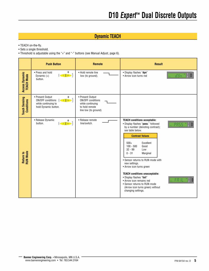
• Press and hold Dynamic (+) button.
• Hold remote line low (to ground).
• Display flashes “dyn” • Arrow icon turns red
Teac
h Se
nsin
g Co
nditi
ons
• Present Output ON/OFF conditions while continuing to hold Dynamic button.
• Present Output ON/OFF conditions while continuing to hold remote line low (to ground)
Ret
urn
to
RU
N M
ode
• Release Dynamic button.
• Release remote line/switch.
TEACH conditions acceptable: • Display flashes “pass,” followed by a number (denoting contrast); see table below.
• Sensor returns to RUN mode with new settings. • Arrow icon turns green TEACH conditions unacceptable: • Display flashes “fail” • Arrow icon remains red • Sensor returns to RUN mode (Arrow icon turns green) without changing settings.
Dynamic TEACH
• TEACH on-the-fly. • Sets a single threshold. • Threshold is adjustable using the “+” and “-” buttons (see Manual Adjust, page 6).
T T T
T TT T T T T
T T T
T TT T T T T
T T T
T TT T T T T
dynamic
static
dynamic
static
dynamic
static
Contrast Values 500+ Excellent 100 - 500 Good 32 - 99 Low 0 - 31 Marginal

D10 Expert™ Dual Discrete Outputs
6 P/N 64154 rev. D Banner Engineering Corp. • Minneapolis, MN U.S.A.
www.bannerengineering.com • Tel: 763.544.3164
Single-Point Static TEACH
• Used to set a single ON condition. • All other conditions (both lighter and darker) will result in an OFF output. • Target ON condition sensitivity is adjustable using the “+” and “-” buttons (see Manual Adjust, below).
Push Button Remote 0.04 sec. ≤ T ≤ 0.8 sec.
Result
Acce
ss T
EACH
Mod
e • Press and hold Static (-) button.
• Display flashes “1st” • Arrow icon turns red
• Present target to learn. • Single-pulse the remote line.
• Display flashes “2nd” • Arrow icon turns red
Teac
h Se
tpoi
nt
(Out
put O
N)
Cond
ition
• Present target to learn. • Double-click the Static button.
• Double-pulse the remote line.
TEACH conditions acceptable: • Display flashes “sngl,” then “pt” twice • Sensor returns to RUN mode with new settings. • Arrow icon turns green TEACH conditions unacceptable: • Display flashes “fail” and returns to “1st” • Arrow icon remains red • After 60 seconds, sensor returns to RUN mode (Arrow icon turns green) without changing settings.
T T T
T TT T T T T
T T T
T TT T T T T
Push Button Remote Result
Man
ual A
djus
t
• Click “+” to increase, or click “-” to decrease.
• Not available with remote programming.
• Display briefly flashes the threshold setpoint value as it is being changed. or • Display flashes “inc” or “dec” as single-point tolerance is adjusted.
Manual Adjust
• May be used at any time sensor is in RUN mode. • Fine-tunes the sensing thresholds or adjusts sensitivity to the single-point target conditions.
dynamic
static
dynamic
static
dynamic
static
dynamic
static
dynamic
static
dynamic
static
dynamic
static
dynamic
static
dynamic
static
dynamic
static
or
or
P/N 64154 rev. D 7
D10 Expert™ Dual Discrete Outputs
Banner Engineering Corp. • Minneapolis, MN U.S.A.www.bannerengineering.com • Tel: 763.544.3164
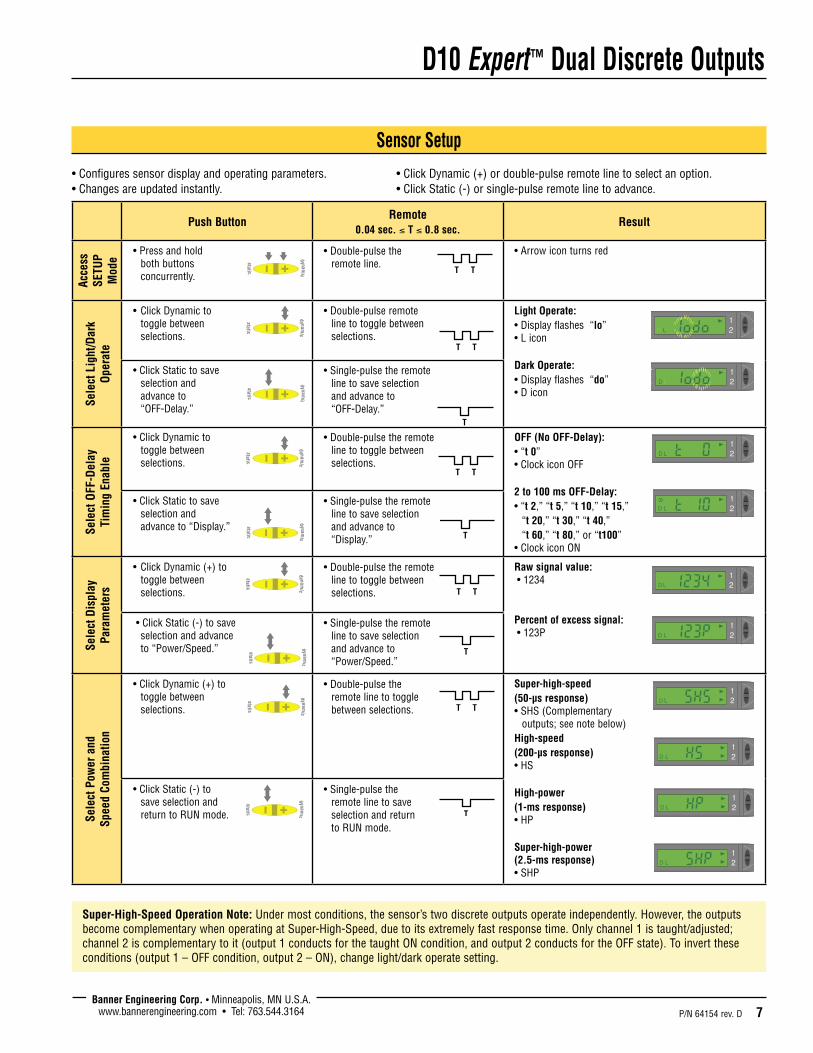
Sensor Setup
• Configures sensor display and operating parameters. • Click Dynamic (+) or double-pulse remote line to select an option. • Changes are updated instantly. • Click Static (-) or single-pulse remote line to advance.
Push ButtonRemote
0.04 sec. ≤ T ≤ 0.8 sec.Result
Acce
ss
SETU
P M
ode
• Press and hold both buttons concurrently.
• Double-pulse the remote line.
• Arrow icon turns red
Sele
ct L
ight
/Dar
k O
pera
te
• Click Dynamic to toggle between selections.
• Double-pulse remote line to toggle between selections.
Light Operate: • Display flashes “lo” • L icon Dark Operate: • Display flashes “do” • D icon
• Click Static to save selection and advance to “OFF-Delay.”
• Single-pulse the remote line to save selection and advance to “OFF-Delay.”
Sele
ct O
FF-D
elay
Ti
min
g En
able
• Click Dynamic to toggle between selections.
• Double-pulse the remote line to toggle between selections.
OFF (No OFF-Delay): • “t 0” • Clock icon OFF 2 to 100 ms OFF-Delay: • “t 2,” “t 5,” “t 10,” “t 15,” “t 20,” “t 30,” “t 40,” “t 60,” “t 80,” or “t100” • Clock icon ON
• Click Static to save selection and advance to “Display.”
• Single-pulse the remote line to save selection and advance to “Display.”
Sele
ct D
ispl
ay
Para
met
ers
• Click Dynamic (+) to toggle between selections.
• Double-pulse the remote line to toggle between selections.
Raw signal value: • 1234 Percent of excess signal: • 123P
• Click Static (-) to save selection and advance to “Power/Speed.”
• Single-pulse the remote line to save selection and advance to “Power/Speed.”
Sele
ct P
ower
and
Sp
eed
Com
bina
tion
• Click Dynamic (+) to toggle between selections.
• Double-pulse the remote line to toggle between selections.
Super-high-speed (50-µs response) • SHS (Complementary outputs; see note below) High-speed (200-µs response) • HS High-power (1-ms response) • HP Super-high-power (2.5-ms response) • SHP
• Click Static (-) to save selection and return to RUN mode.
• Single-pulse the remote line to save selection and return to RUN mode.
T T T
T TT T T T T
T T T
T TT T T T T
T T T
T TT T T T T
T T T
T TT T T T T
T T T
T TT T T T T
T T T
T TT T T T T
dynamic
static
dynamic
static
dynamic
static
dynamic
static
dynamic
static
dynamic
static
T T T
T TT T T T T
Super-High-Speed Operation Note: Under most conditions, the sensor’s two discrete outputs operate independently. However, the outputs become complementary when operating at Super-High-Speed, due to its extremely fast response time. Only channel 1 is taught/adjusted; channel 2 is complementary to it (output 1 conducts for the taught ON condition, and output 2 conducts for the OFF state). To invert these conditions (output 1 – OFF condition, output 2 – ON), change light/dark operate setting.
T T T
T TT T T T T
T T T
T TT T T T T
dynamic
static
dynamic
static
dynamic
static
dynamic
static

D10 Expert™ Dual Discrete Outputs
8 P/N 64154 rev. D Banner Engineering Corp. • Minneapolis, MN U.S.A.
www.bannerengineering.com • Tel: 763.544.3164
Push Button Lockout
• Prevents unwanted adjustments or tampering of the push buttons. • Push buttons can be enabled or disabled only from the remote line and only during normal RUN mode.
Push Button Remote 0.04 sec. ≤ T ≤ 0.8 sec.
Result
Enab
le o
r D
isab
le
Push
But
tons
• Not available with push-button programming.
• From RUN mode, quad-pulse the remote line to toggle between selections.
Push Buttons Disabled: • Display flashes “loc” • Padlock icon appears • Sensor remains in RUN mode Push Buttons Enabled: • Display flashes “uloc” • Padlock icon disappears • Sensor remains in RUN mode
T T T
T TT T T T T
dynamic
static
dynamic
static

P/N 64154 rev. D 9
D10 Expert™ Dual Discrete Outputs
Banner Engineering Corp. • Minneapolis, MN U.S.A.www.bannerengineering.com • Tel: 763.544.3164
Advanced Setup
• Advanced adjustments to previously configured sensor display and operating parameters. • Quad-click Static (-) or quad-pulse remote line before exiting “Power and Speed” settings to enter this mode. • Click Dynamic (+) or double-pulse remote line to select an option. • Click Static or single-pulse remote line to advance. • Changes are updated instantly.
Push Button Remote 0.04 sec. ≤ T ≤ 0.8 sec.
Result
Ente
r SE
TUP
Mod
e
• From “Power and Speed” mode, quad-click Static (-) button.
• From “Power and Speed” mode, quad-click the remote line.
• Arrow icon remains red • Display shows “Tracking Enabled” option.
Trac
k En
able
• Click Dynamic (+) to toggle between selections.
• Double-pulse the remote line to toggle between selections.
Sets output 2 identical to output 1 Tracking disabled: • Display shows “tr n” Tracking enabled: • Display shows “tr y”
• Click Static (-) to save selection and advance to “Factory Default.”
• Single-pulse the remote line to save selection and advance to “Factory Default.”
Fact
ory
Def
ault
Setti
ngs • Click Dynamic (+)
to toggle between selections.
• Double-pulse the remote line to toggle between selections.
Returns to factory default factory settings Factory Default Settings Not Selected: • Display shows “fd n” Factory Default Settings Selected: • Display shows “fd y”
• Click Static (-) to advance to “Display Orientation.”
• Single-pulse the remote line to advance to “Display Orientation.”
Dis
play
Ori
enta
tion
• Click Dynamic (+) to toggle between selections.
• Double-pulse the remote line to toggle between selections.
Inverts display to read “upside-down” Normal: • For example: 1234 Inverted: • For example: NOTE: Icons do not invert.
• Click Static (-) to return to RUN mode.
• Single-pulse the remote line to return to RUN mode.
1234
T T T
T TT T T T T
T T T
T TT T T T T
T T T
T TT T T T T
T T T
T TT T T T T
T T T
T TT T T T T
T T T
T TT T T T T
T T T
T TT T T T T
dynamic
static
dynamic
static
dynamic
static
dynamic
static
dynamic
static
dynamic
static
dynamic
static

D10 Expert™ Dual Discrete Outputs
10 P/N 64154 rev. D Banner Engineering Corp. • Minneapolis, MN U.S.A.
www.bannerengineering.com • Tel: 763.544.3164
Self-Diagnostic Error Modes
In the unlikely event that the setup parameters are lost or become corrupt, the display will continuously scroll: “USEr PSF Error.” Reteach the sensor to recover. If the problem persists, contact your Banner representative for further information.
Gate Input
The pink wire is configured as a gate input. When this wire is pulled low (i.e., to the sensor ground), it inhibits the outputs from switching, while all other sensor functions continue to be enabled. This feature is useful for controlling when the outputs are allowed to change states. Gate input function response time is 1 millisecond.
Required Fiber-Optic Cable Banner P-Series plastic fibers
Sensing Beam Visible red, 680 nm, or Visible green, 525 nm, depending on model
Supply Voltage and Current 12 to 24V dc (10% maximum ripple) at less than 65 mA, exclusive of load
Supply Protection Circuitry Protected against reverse polarity and transient voltage
Output Configuration 2 NPN or 2 PNP, depending on model
Output Rating 150 mA maximum load OFF-state leakage current: < 10 µA at 24V dc ON-state saturation voltage: NPN < 1.5V at 150 mA load PNP < 2.5V at 150 mA load
Output Protection Circuitry Protected against false pulse on power-up and continuous short-circuit
Output Response Time Programmable, 50 microseconds, 200 microseconds, 1 millisecond, 2.5 millisecondsNOTE: < 1 second delay on power-up; outputs do not conduct during this time.
Adjustments Push-button or remote programming of response time, OFF-delay, light/dark operate, and display
Indicators Four-digit digital display plus LED indicators for active channel, push-button lockout, OFF-delay and light/dark operate selection; 2 yellow output indicators
Construction Black ABS/polycarbonate alloy (UL94 V-0 rated) housing, clear polycarbonate cover
Environmental Rating NEMA 1, IEC IP50
Connections PVC-jacketed 2 m or 9 m (6.5' or 30') 6-wire integral cable or integral 6-pin Pico-style quick-disconnect
Operating Conditions Temperature: -20° to +55°C (-4° to +131°F) Storage Temperature: -20° to +80°C (-4° to +175°F) Max. Rel. Humidity: 90% @ 50°C (non-condensing)
Number of Devices, Stacked
Ambient Temperature Rating
Load Specification
3 55°C 150 mA
7 50°C 50 mA
10 45°C 50 mA
Installation 35 mm DIN rail or included mounting bracket
Certifications
Specifications

P/N 64154 rev. D 11
D10 Expert™ Dual Discrete Outputs
Banner Engineering Corp. • Minneapolis, MN U.S.A.www.bannerengineering.com • Tel: 763.544.3164
Dimensions
10.0 mm (0.39")
35.1 mm (1.38")
10.0 mm (0.39")
15.2 mm(0.60")
2x C'sink ø8.0 mm (0.31") 3.2 mm (0.13") deep ø4.4 mm (0.18") thru
2x 3.5 mm (0.14")
5.0 mm(0.20")
8.6 mm (0.34")
25.4 mm (1.00")
16.0 mm (0.63")
2 x ø3.3 mm (0.13")
2x ø3.2 mm (0.13")
2.5 mm (0.10")
5.0 mm (0.20")
M3 Hardware included: Lock Washer (2) Flat Washer (2) Screws (2) Hex Nuts (2)
Included Bracket Dimensions
61.3 mm(2.42")
68.1 mm(2.68")
Plastic FiberEmitter Port
Plastic FiberReceiver Port
10.5 ± 0.2 mm (typ.)(0.41")
Mounting Bracket(included)
Slides Up toRelease Fibers
35.9 mm(1.41")
7.6 mm0.30"
9.8 mm(0.39")

Banner Engineering Corp., 9714 Tenth Ave. No., Minneapolis, MN USA 55441 • Phone: 763.544.3164 • www.bannerengineering.com • Email: [email protected]
D10 Expert™ Dual Discrete Outputs
WARRANTY: Banner Engineering Corp. warrants its products to be free from defects for one year. Banner Engineering Corp. will repair or replace, free of charge, any product of its manufacture found to be defective at the time it is returned to the factory during the warranty period. This warranty does not cover damage or liability for the improper application of Banner products. This warranty is in lieu of any other warranty either expressed or implied.
P/N 64154 rev. D
Accessories
Pico-Style Quick-Disconnect CablesCable: PUR jacket, polyurethane connector body, POM snap-lock couplingConductors: 26 or 24 AWG high-flex stranded, gold-plated contactsTemperature: -40° to +90°C (-40° to +194°F)Voltage Rating: 30V ac/36V dc
Style Model Length Dimensions Pin-out
6-Pin Straight
PKG6Z-2 2 m (6.5')
PKG6Z-9 9 m (30')
6-Pin Right-angle
PKW6Z-2 2 m (6.5')
PKW6Z-9 9 m (30')
28 mm max.(1.1")
ø 10 mm max.(0.4")
20 mm(0.8")
25 mm max.(1.0")
ø12 mm max.(0.5")
Brown Wire
Gray Wire
Pink Wire
Blue Wire
Black Wire
White Wire
HookupsNPN Output Models PNP Output Models
bu12-24V dc–
+
1
2
Teach
Gate
bn
wh
bk
gy
pk
Load
Load
bn12-24V dc+
–
1
2
Teach
Gate
bu
wh
bk
gy
pk
Load
Load
NOTE: QD hookups are functionally identical.