Experiments with CNC -DJ upgrade from 3020Tvalky.eu/data/hardware/cnctutorial_draft.pdf ·...
11
Experiments with CNC In april 2013 I decided to buy a CNC machine. I did not need it for serious production, I just wanted to learn something new. I was looking around for the cheapest CNC available and found this: “220V CNC 3020T-DJ upgrade from 3020T 3020 Router with 230W 11000RPM spindle” As always when I am buying something more expensive, I was trying to find out whether this machine is reliable and can be used to make PCBs. I was fed up with the chemicals and complicated process of producing PCBs by photo etching. The CNC3020 is the smallest version of cheap chinese CNC’s, if you are looking for something bigger, you can try CNC3040 or CNC6040, the numbers 30 20 specify the plate size. So for now I have been never making larger PCBs than 12x12 centimeters, so CNC3020 was the best choice for me. Steven Pearson has written nice review of this CNC and he also shows how to produce PCBs also with nice videos. He shows his method of fixing the PCB on place with duct tape. [http://makerflux.com/projects/cnc/cnc_isolation_milling_1]
Transcript of Experiments with CNC -DJ upgrade from 3020Tvalky.eu/data/hardware/cnctutorial_draft.pdf ·...

Experiments with CNC In april 2013 I decided to buy a CNC machine. I did not need it for serious production, I just wanted to
learn something new. I was looking around for the cheapest CNC available and found this: “220V CNC 3020T-DJ upgrade from 3020T 3020 Router with 230W 11000RPM spindle”
As always when I am buying something more expensive, I was trying to find out whether this machine
is reliable and can be used to make PCBs. I was fed up with the chemicals and complicated process of producing PCBs by photo etching. The CNC3020 is the smallest version of cheap chinese CNC’s, if you are looking for something bigger, you can try CNC3040 or CNC6040, the numbers 30 20 specify the plate size. So for now I have been never making larger PCBs than 12x12 centimeters, so CNC3020 was the best choice for me.
Steven Pearson has written nice review of this CNC and he also shows how to produce PCBs also with nice videos. He shows his method of fixing the PCB on place with duct tape.
[http://makerflux.com/projects/cnc/cnc_isolation_milling_1]
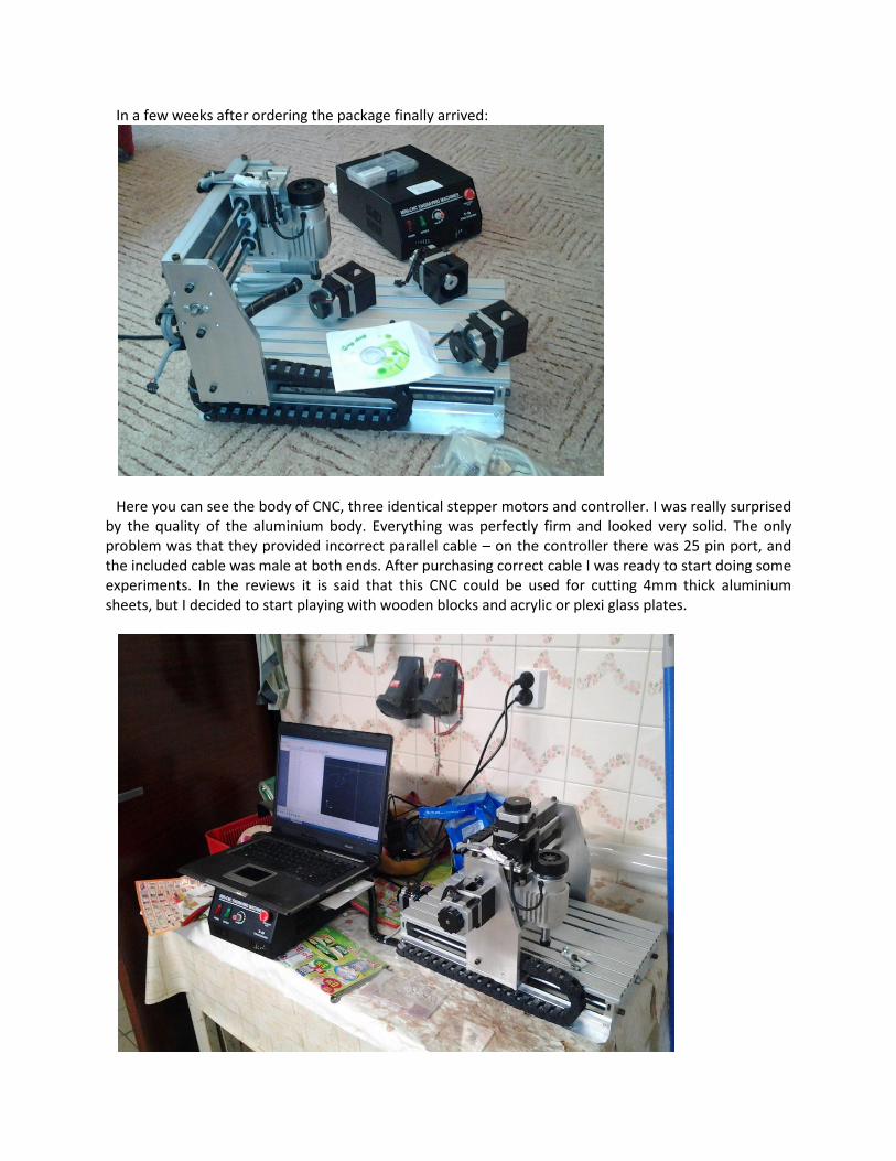
In a few weeks after ordering the package finally arrived:
Here you can see the body of CNC, three identical stepper motors and controller. I was really surprised
by the quality of the aluminium body. Everything was perfectly firm and looked very solid. The only problem was that they provided incorrect parallel cable – on the controller there was 25 pin port, and the included cable was male at both ends. After purchasing correct cable I was ready to start doing some experiments. In the reviews it is said that this CNC could be used for cutting 4mm thick aluminium sheets, but I decided to start playing with wooden blocks and acrylic or plexi glass plates.

On the installation CD there was a application called Mach3, it uses parallel port to communicate with the stepper motor controller. In printed manual there were instruction how to configure the Mach3 to work with CNC3020. Mach3 is universal CNC controller and it is necessary to set up the communication pins, resolution and acceleration/decleration speeds. To make the controller as cheap as possible, all the logic is implemented in Mach3 software and the controller is just a simple stepper motor driver. For each motor it uses 2 logical signals – one for direction and the second for moving. So the application is setting the logical levels on the parallel port 20 000 times per second. For connecting the CNC to computer you cannot use USB to parallel cables, because the USB technology does not allow you to achieve reliable timing. I was lucky that I had laptop running XP with parallel port at home…
So here is my first experiment:
I used Adobe Illustrator for designing some simple label. Then I used some tool (I cannot remember
the name) to convert the DXF into Gcode, then I loaded the Gcode into Mach3 and started cutting. Everything was fine, but I forget to consider the size of drill I used, so the result was in some places very thin and easy to break. For drilling I used 30 degree cone shaped drill. The CNC3020 comes with few bits as accessory – one end mill (looks like regular drill bit, but it has flat head), some 30 degree V bits and few flat head router bits. Read about them here: http://100kgarages.com/blog/2013/04/cnc-router-bits-demystified/
If you don’t want to be surprised why the result looks completely different than your design in Adobe Illustrator, follow this short tutorial:
Create new document with reasonable size (e.g. 10x4 cm)
Use type tool with some script font (in my case Brush Script Std Medium) to create a label
Increase the font size so that the label covers all the document
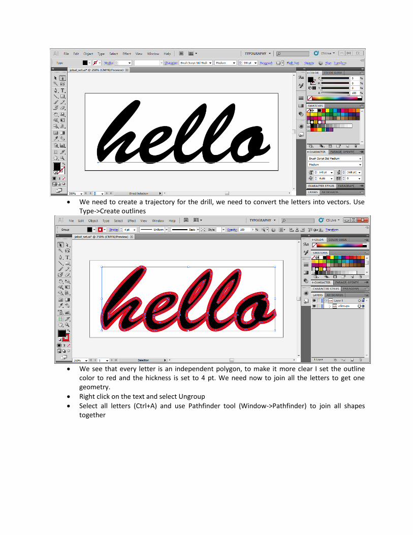
We need to create a trajectory for the drill, we need to convert the letters into vectors. Use
Type->Create outlines
We see that every letter is an independent polygon, to make it more clear I set the outline
color to red and the hickness is set to 4 pt. We need now to join all the letters to get one geometry.
Right click on the text and select Ungroup
Select all letters (Ctrl+A) and use Pathfinder tool (Window->Pathfinder) to join all shapes together

Now it looks fine, if you want to modify the geometry you can use the Direct Selection Tool (A)
Use the Stroke tool (Windows->Stroke) and change the Corners to Round Join.
Finally set the stroke size to 3mm if your are using regular 1/8” drill bit, or if you are using cone
shaped bit, you need to calculate the diameter manually. In my case it was about 1.4 milimeters diameter with 30° conical bit and 2mm thick acrylic plate. Simply type “1.4mm” into stroke size editbox in the Compound Path panel under the main menu and this is what you get:
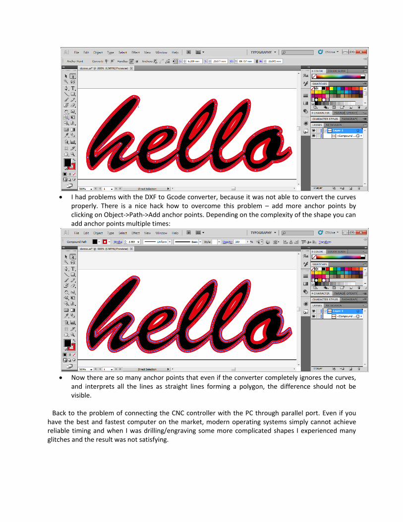
I had problems with the DXF to Gcode converter, because it was not able to convert the curves
properly. There is a nice hack how to overcome this problem – add more anchor points by clicking on Object->Path->Add anchor points. Depending on the complexity of the shape you can add anchor points multiple times:
Now there are so many anchor points that even if the converter completely ignores the curves,
and interprets all the lines as straight lines forming a polygon, the difference should not be visible.
Back to the problem of connecting the CNC controller with the PC through parallel port. Even if you have the best and fastest computer on the market, modern operating systems simply cannot achieve reliable timing and when I was drilling/engraving some more complicated shapes I experienced many glitches and the result was not satisfying.
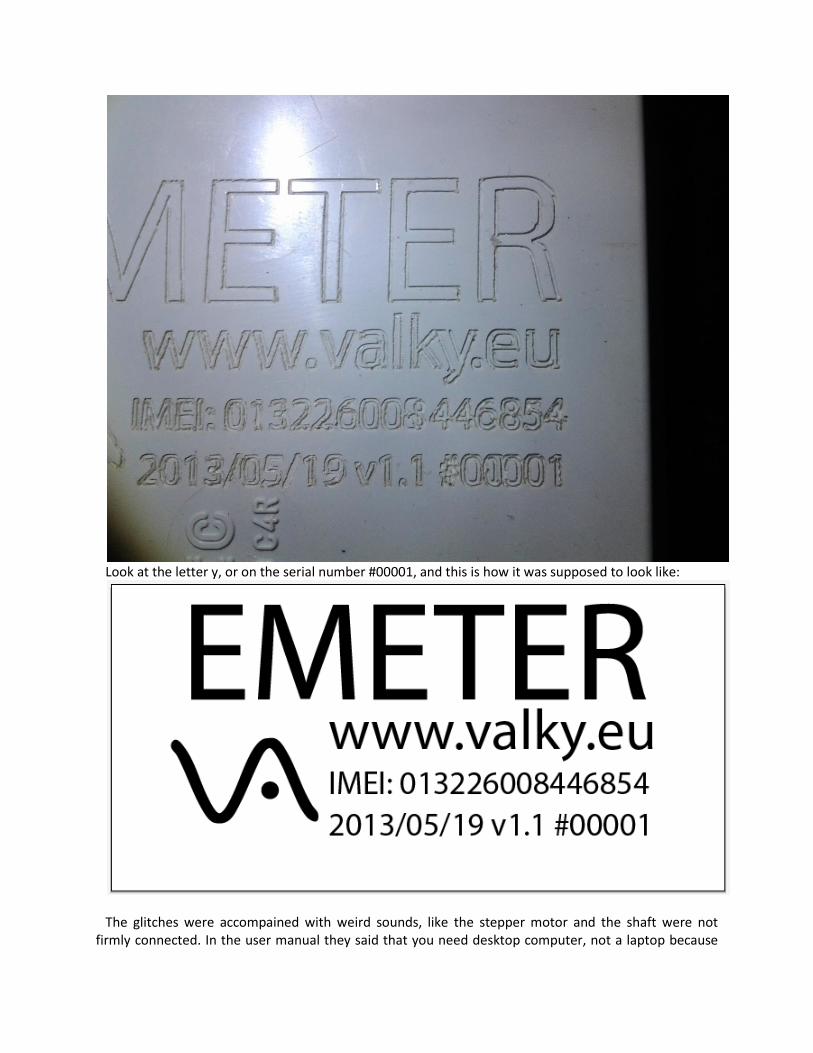
Look at the letter y, or on the serial number #00001, and this is how it was supposed to look like:
The glitches were accompained with weird sounds, like the stepper motor and the shaft were not
firmly connected. In the user manual they said that you need desktop computer, not a laptop because
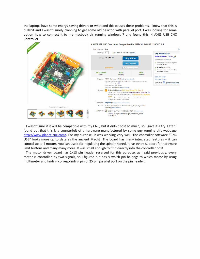
the laptops have some energy saving drivers or what and this causes these problems. I knew that this is bullshit and I wasn’t surely planning to get some old desktop with parallel port. I was looking for some option how to connect it to my macbook air running windows 7 and found this: 4 AXES USB CNC Controller
I wasn’t sure if it will be compatible with my CNC, but it didn’t cost so much, so I gave it a try. Later I
found out that this is a counterfeit of a hardware manufactured by some guy running this webpage http://www.planet-cnc.com/. For my surprise, it was working very well. The controller software “CNC USB” looks more up to date as the ancient Mach3. The board has many integrated features – it can control up to 4 motors, you can use it for regulating the spindle speed, it has event support for hardware limit buttons and many many more. It was small enough to fit it directly into the controller box!
The motor driver board has 2x13 pin header reserved for this purpose, as I said previously, every motor is controlled by two signals, so I figured out easily which pin belongs to which motor by using multimeter and finding corresponding pin of 25 pin parallel port on the pin header.
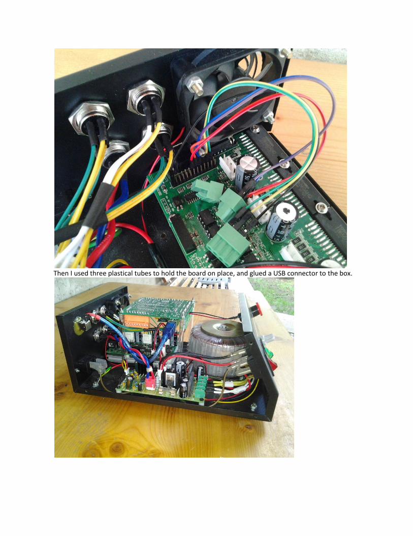
Then I used three plastical tubes to hold the board on place, and glued a USB connector to the box.

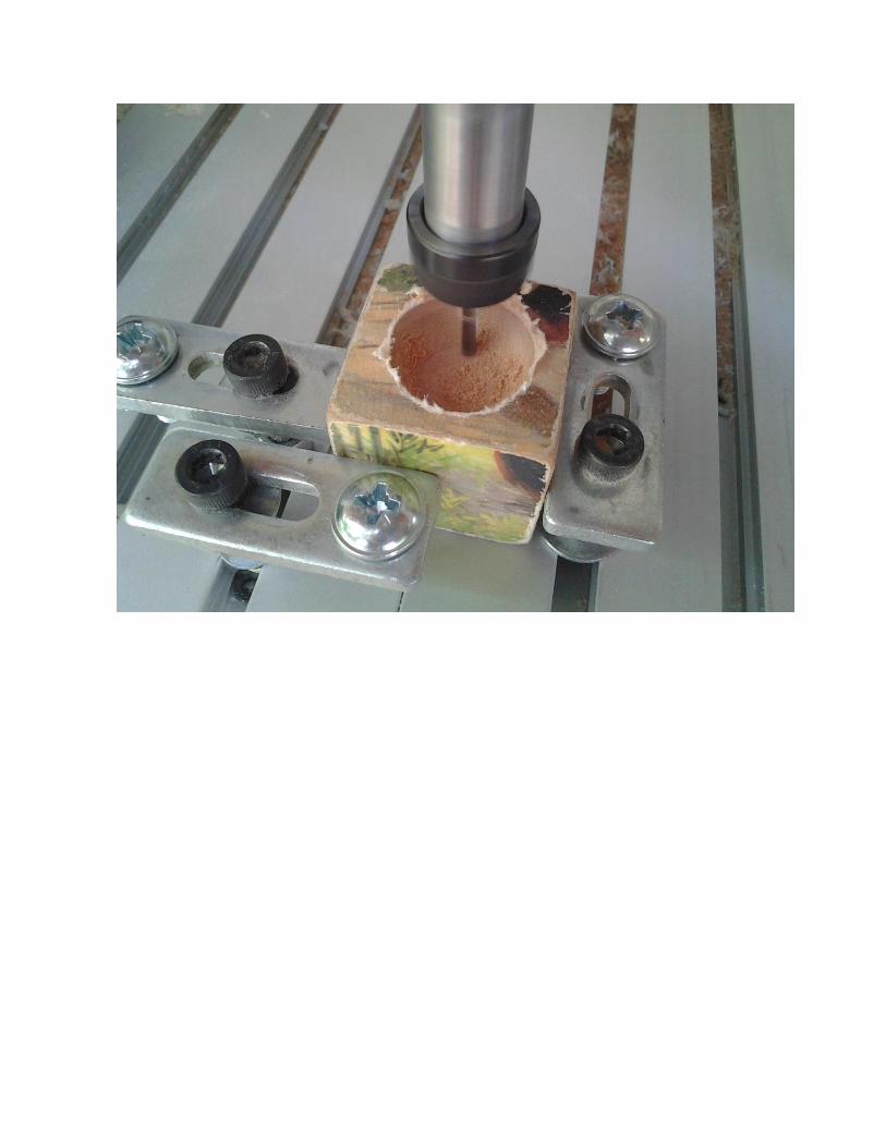
…drilling a spherical hole into wooden block. This task required 100% accuracy
![MITSUBISHI CNC DRIVE · PDF filebnp-a1227-c[eng] general catalog mds-d2/dh2 series mds-dm2 series mds-dj series mitsubishi cnc drive system bnp-a1227-c [eng] cnc drive (english) bnp-a1227-c[eng]](https://static.fdocuments.in/doc/165x107/5abcb68f7f8b9a567c8e1e8e/mitsubishi-cnc-drive-eng-general-catalog-mds-d2dh2-series-mds-dm2-series-mds-dj.jpg)


![08123301994 [Telkomsel] dj paling hits, dj paling ngetop, dj indonesia](https://static.fdocuments.in/doc/165x107/589e1b5d1a28ab605b8b5a4f/08123301994-telkomsel-dj-paling-hits-dj-paling-ngetop-dj-indonesia.jpg)