
Experiments to Investigate Video Conversation Quality ... · Experiments to Investigate Video...
67
Experiments to Investigate Video Conversation Quality Enhancements on Mobile Platforms over IP Networks using WebRTC ALEXANDER MALMSTEDT Master of Science Thesis Stockholm, Sweden 2012
Transcript of Experiments to Investigate Video Conversation Quality ... · Experiments to Investigate Video...

Experiments to Investigate Video
Conversation Quality Enhancements on Mobile Platforms
over IP Networks using WebRTC
A L E X A N D E R M A L M S T E D T
Master of Science Thesis Stockholm, Sweden 2012

Experiments to Investigate Video
Conversation Quality Enhancements on Mobile Platforms
over IP Networks using WebRTC
A L E X A N D E R M A L M S T E D T
DD221X, Master’s Thesis in Computer Science (30 ECTS credits) Degree Progr. in Computer Science and Engineering 300 credits Royal Institute of Technology year 2012 Supervisor at CSC was Josephine Sullivan Examiner was Stefan Carlsson TRITA-CSC-E 2012:043 ISRN-KTH/CSC/E--12/043--SE ISSN-1653-5715 Royal Institute of Technology School of Computer Science and Communication KTH CSC SE-100 44 Stockholm, Sweden URL: www.kth.se/csc

AbstractThis project is about implementing and evaluating theWeb-RTC library for its suitability in enabling mobile video con-versations on the iOS operating system. Two video codecsand two protection techniques from the library were evalu-ated for their effectiveness in providing a good video qual-ity in the conversation. These codecs are called I420 andVP8, and the techniques are called negative acknowledg-ment (NACK) and forward error correction (FEC). NACKturned out to perform best when the delay in the networkis low, and the FEC performed best when there is plenty ofavailable bandwidth. VP8 turned out to be most suitablevideo codec to use in mobile environment due to its lowbandwidth requirements.
An improvement to the FEC technique that changeshow the packets are protected, called unequal error pro-tection (UEP), was also implemented and evaluated. Theunequal error protection did only provide a minimal im-provement in performance, but some suggestions are madeon how the technique could be further improved.

ReferatExperiment rörande tekniker för uttökandeav kvalitén för videokonversationer på mobilaplattformar över IP-nätverk med WebRTC
Det här projektet handlar om att implementera och utvär-dera WebRTC-biblioteket för dess lämplighet att kunna ge-nomföra mobila videokonversationer på iOS-operativsystemet.Två videokodekar och två skyddstekniker från biblioteketutvärderades med avseende på hur effektivt de bidrar tillen förbättrad videokvalitét i konversationen. De videoko-dekerna heter I420 och VP8, och skyddsteknikerna kallasför negative acknowledgment (NACK) och forward errorcorrection (FEC). NACK visade sig prestera bäst när för-dröjningen var låg i nätverket och FEC presterade bäst närdet fanns gott om tillgänglig bandbredd. VP8 visade sig va-ra mest lämplig som videokodek i ett mobilt sammanhangpå grund av dess låga bandbreddskrav.
En förbättring till FEC-tekniken som förändrar hur pa-keten skyddas, kallad unequal error protection (UEP), im-plementerades och utvärderades även. Skyddstekniken bi-drog endast till en minimal förbättring, men några förslagpå hur tekniken kan uttökas föreslås.

Contents
1 Introduction 1
2 Background 32.1 The history of telephony . . . . . . . . . . . . . . . . . . . . . . . . . 3
2.1.1 Ñôïšé . . . . . . . . . . . . . . . . . . . . . . . . . . . . . . . 42.1.2 Conversation quality . . . . . . . . . . . . . . . . . . . . . . . 5
2.2 The human cognitive processing . . . . . . . . . . . . . . . . . . . . . 82.2.1 Spatial masking . . . . . . . . . . . . . . . . . . . . . . . . . . 82.2.2 Color perception . . . . . . . . . . . . . . . . . . . . . . . . . 8
2.3 Video codec . . . . . . . . . . . . . . . . . . . . . . . . . . . . . . . . 92.4 Network transportation . . . . . . . . . . . . . . . . . . . . . . . . . 10
2.4.1 The mobile network environment . . . . . . . . . . . . . . . . 112.4.2 Forward error correction . . . . . . . . . . . . . . . . . . . . . 112.4.3 Negative acknowledgment . . . . . . . . . . . . . . . . . . . . 13
2.5 The WebRTC library . . . . . . . . . . . . . . . . . . . . . . . . . . . 142.6 Previous work . . . . . . . . . . . . . . . . . . . . . . . . . . . . . . . 15
2.6.1 Other video conversation applications . . . . . . . . . . . . . 152.6.2 Improving video quality . . . . . . . . . . . . . . . . . . . . . 15
3 Method 173.1 Implementation phase . . . . . . . . . . . . . . . . . . . . . . . . . . 173.2 Experiment setup . . . . . . . . . . . . . . . . . . . . . . . . . . . . . 183.3 Simulated environment . . . . . . . . . . . . . . . . . . . . . . . . . . 183.4 Hardware used . . . . . . . . . . . . . . . . . . . . . . . . . . . . . . 193.5 Measurement metrics . . . . . . . . . . . . . . . . . . . . . . . . . . . 193.6 Evaluated techniques . . . . . . . . . . . . . . . . . . . . . . . . . . . 20
4 Codec comparison with fixed frame size 234.1 Results . . . . . . . . . . . . . . . . . . . . . . . . . . . . . . . . . . . 23
4.1.1 I420 codec . . . . . . . . . . . . . . . . . . . . . . . . . . . . . 234.1.2 VP8 codec . . . . . . . . . . . . . . . . . . . . . . . . . . . . 27
4.2 Analysis . . . . . . . . . . . . . . . . . . . . . . . . . . . . . . . . . . 294.3 Conclusions . . . . . . . . . . . . . . . . . . . . . . . . . . . . . . . . 31

5 Protection comparison with varying frame size 335.1 Results . . . . . . . . . . . . . . . . . . . . . . . . . . . . . . . . . . . 335.2 Analysis . . . . . . . . . . . . . . . . . . . . . . . . . . . . . . . . . . 365.3 Conclusions . . . . . . . . . . . . . . . . . . . . . . . . . . . . . . . . 37
6 Unequal error protection 396.1 Results . . . . . . . . . . . . . . . . . . . . . . . . . . . . . . . . . . . 396.2 Analysis . . . . . . . . . . . . . . . . . . . . . . . . . . . . . . . . . . 406.3 Conclusions . . . . . . . . . . . . . . . . . . . . . . . . . . . . . . . . 40
7 Finishing thoughts 437.1 Conclusions about the WebRTC library . . . . . . . . . . . . . . . . 437.2 Where to go from here . . . . . . . . . . . . . . . . . . . . . . . . . . 43
Bibliography 45
Appendices 47
A Word list 47
B Experiment data 49B.1 I420 data . . . . . . . . . . . . . . . . . . . . . . . . . . . . . . . . . 49B.2 VP8 data . . . . . . . . . . . . . . . . . . . . . . . . . . . . . . . . . 52B.3 Unequal error protection data . . . . . . . . . . . . . . . . . . . . . . 60

Chapter 1
Introduction
Transportation of voice calls through IP networks is an idea that has been realisedand improved by a number of different applications over time. Recently, the conceptof video calls has also become more and more developed. Adding video to a voicecall introduces a number of different obstacles to overcome in order to provide agood user experience. Things like packet loss, audio and video synchronization andnetwork delays are some of the challenges that must be mastered in order to developsuch an application.
In this report, I start by explaining the concept of a conversation that uses audioand video has evolved over time. I also dig into the theory behind perception ofquality for audio and video sequences. How come some video segments seems to beof better quality than others? This leads to a description of some of the differentmethods and techniques that can be used to improve video quality in an audio/videoconversation. The focus in this project is mainly towards protection techniques thatrelates to the network aspects of a mobile video conversation.
During the project, I implemented a prototype that uses the WebRTC libraryto provide a video conversation between two mobile phones.[GI] Since the WebRTClibrary is not yet available for iOS operating system, most of the implementationwork consisted of porting the library to the mobile architecture and getting it to runproperly. When I started the project, I was not sure if the WebRTC library wouldwork at all for mobile phones. The analysis in this project is aimed specificallytowards this library, to determine if it is a good candidate for mobile usage ornot. In the end, I managed to implement the library, analyzed some of the videoprotection techniques in it, and also decided to implement an improvement to oneof them, called unequal error protection.
In appendix A the reader finds a word list that explains some of the terms usedin this document.
1


Chapter 2
Background
This chapter contains some background information about mobile video conversa-tions. Here, I explain some of the history behind video conversations, I introducethe concepts of noise and quality in video conversations, and try to describe how acodec operates. There is also a more detailed explanation of the protection tech-niques that were evaluated in the experiments.
2.1 The history of telephony
It all started with the invention of the telephone in the late 1870s. Back then, therewere of course no networks created yet for telephony. Telephones had to be wiredin pairs, so if you wanted to talk to different people, well, then you simply had tobuy more telephones. Ringing someone up was carried out by whistling into thetransmitter until the other person could hear it.
However, telephony soon started taking on the principles of the preexisting teleg-raphy network. The telephones were connected to local telephone switches, whichin turn were connected to other telephone switches until they spanned countries andcontinents. This was the beginning of the creation of the public switched telephonenetwork (PSTN). As the number of users grew, so did the networks, and soon vari-ous quality of service (QoS) guarantees needed to be implemented in order to handle
3

CHAPTER 2. BACKGROUND
the capacity. This was basically a collection of aspects that could be changed orused to improve the quality of the call, e.g. loss, signal-to-noise ratio, cross-talk,echo, interrupts and loudness levels.
Nowadays, almost all parts of the PSTN has been converted to use digital signalsinstead of analog signals, and offers connectivity for both mobiles as well as fixedtelephones.[Wikd] Most voice over IP (VoIP) calls today are still interacting witha PSTN in some way. This means that many of the quality problems that existin a PSTN have been transfered to VoIP calls. Additionally, new impairments arecreated when transmitting data over a VoIP network; impairments that may neverhave been seen in a traditional PSTN.
The central cause of the majority of problems introduced with VoIP calls is;trying to send real-time media over a non-real-time data network. The IP networksused today were never designed to be used in a real-time manner. The engineersthat invented VoIP calls did decide to give it a try anyways.
2.1.1 Ñôïšé
Since noise is a very central part of this report, this is probably an appropriatetime to define its meaning. The general meaning of noise in audio and video callsis distortion, that is, any undesired characteristics that degrades the media signal.The type of noise can be divided into two classes; additive and subtractive distortion.Background noise and amplification are examples of additive distortion, while signalloss is of the subtractive type.
Figure 2.1. Quantizing an analog signal to a digital signal results in loss of infor-mation. Image from Wikipedia.[Wike]
Noise can appear in many shapes and forms, and at many points in a VoIP conversa-tion. Noise can be temporary, like packet loss bursts, or permanent, like transcodingdistortions of a particular codec. Permanent noise tends to be easier to reduce due to
4

2.1. THE HISTORY OF TELEPHONY
their predictiveness. Some types of noise are not exclusive to VoIP environments,and might therefore not be possible to improve with VoIP QoS. One example isbackground noise, sounds in the environment of the user that bleed into the call,like keyboard typing or strong wind. Another one is signal level noise, where theelectrical interference at the signal level can cause the media signal to become faint.The third one is quantizing, which occurs when mapping an analog signal to a dig-ital, see figure 2.1. The latter one is practically unavoidable, however, it is possibleto select a codec that minimizes the signal distortion. [Wal05] Figure 2.2 showsexamples of various amounts of noise in a video frame using the VP8 codec.
The elimination of noise in a media signal is commonly referred to as noisereduction. Noise reduction techniques are of various kinds and effectiveness. Anexample is when the user presses the phone receiver closely to his ear, while plugginghis other ear with a finger, thus boosting the signal level of the call. A quite primitivetechnique, which still can be relatively effective. The noise reduction techniques usedin VoIP are usually electronic though.
Figure 2.2. Example of video noise with the VP8 codec. The left image has no noise,the center image has some noise (mostly noise in the color), and the third image hasa substantial amount of noise.
2.1.2 Conversation qualityThe incentive behind using noise reduction techniques in VoIP is quite clear; toincrease the quality of the conversation. However, the concept of quality in a VoIPconversation is not as clear. It is very difficult to separate the subjective experienceof a human listener from the objective evaluation of noise. Accordingly, one mustunderstand that the cognitive aspects of human perception of audio and video areimportant to consider when creating VoIP systems. For example, if a sudden burstof noise occurs in voice sample, the perceived quality will be worse if the noise
5

CHAPTER 2. BACKGROUND
occurs at the end of the sample instead of the beginning.[Cla01] Other things likethe mood and expectations of the listener can also affect the perceived quality. Thehuman aspects can have as big impact as the pure technical ones, so it is importantnot to neglect them.
Figure 2.3. Clarity, delay and echo combines to make the audio conversation qualityspace.
Audio quality
When addressing conversation quality measurements of the audio part in VoIP, thereexists three quality metrics primarily used for evaluation. These are called clarity,echo and delay, depicted in figure 2.3, and together, they combine to make theaudio conversation quality space. There does not exist a well-defined relationshipbetween these metrics, but in general the audio conversation quality improves whenthe clarity is increased, the delay is short and the echo is reduced.[Har03]
Clarity is the lack of distortion, the clearness in the audio. Clarity is tradi-tionally measured subjectively, using a mean opinion score (MOS), however, moreobjective measurement techniques also exist. Disturbance in clarity is usually causedby jitter and packet loss.
Delay is a measure of the time it takes to send the signal from the sender tothe receiver. It is the combined time of network processing and packet transport.Since delay does not add distortion to the sound signal, it decreases the quality ofthe conversation without affecting the actual sound. At about 250 milliseconds ofdelay, the users will start to notice the delay in the conversation. Between 300-500 milliseconds the conversation starts to become more and more difficult, andwhen the delay rises above 500 milliseconds it can render normal communication
6

2.1. THE HISTORY OF TELEPHONY
impossible.[Har03] A PSTN has a delay of around 10 milliseconds, while a VoIPnetwork can have an unavoidable delay of about 50-100 milliseconds due to process-ing. The variation in delay times is a phenomenon called jitter. This has the effectthat packets arrive out of order. Small amounts of jitter can be tolerated using ajitter buffer, however, there is limit for how late a packet can be before it has to bedropped, which adds distortion to the sound signal.
Echo is when the sound signal from the sender is reflected back to the sendersear. Similar to delay, echo has more of an effect on the perceived quality of theconversation, rather than the actual sound quality. An increased delay can alsomagnify the effects of echo. Echo effects exist in PSTNs too, but the minimal delaymakes them much less noticeable.
Video quality
For the video aspect of the conversation, the clarity and the delay metrics stillapplies in pretty much the same way. The problems with echo however, do not existsince the video signal will not be reflected back to the sender unless the receiveractively tries to send a signal of his own screen.
Like the audio signal, the clarity of the video signal is a subjective matter. Ittoo is usually benchmarked using a MOS, but other metrics like mean squared error(MSE) and peak signal-to-noise ratio (PSNR) can be used to actually calculatethe pixel difference between two reference images. MSE is thus a metric that isnot readily available during a real-time video conversation, it has to be calculatedafterwards.
The delay metric is in most senses identical in both audio and video. Thecauses behind the delay are the same, network processing and packet transport. Ina video conversation, where the audio and video is synchronized, the same delayrequirements can be made on both audio and video.
Figure 2.4. Clarity and delay combines to make the video conversation quality space.
As such, it is possible to transfer the concept of the audio quality conversation space
7

CHAPTER 2. BACKGROUND
to its video counterpart, and call it the video quality conversation space (seen infigure 2.4. This quality space has only the delay and the clarity metrics.
2.2 The human cognitive processingThe human brain has fantastic auditory and visual systems. They enable us toevaluate situations in fractions of a second, detect minimal changes in signals andmake advanced predictions. Systems of such enormous complexity tend to haveseveral interesting properties. For example the human brain is capable of filling inthe gaps when parts of an audio or video signal is missing or distorted. This allowsus to tolerate a certain amount of noise without affecting the perceived quality ofthe signal too much.
The brain is however far more sensitive towards gaps in audio than in video.The reason behind this is that the brain is just more focused at handling video. Itis the most essential of our senses, and an estimated 80-90 % of all neurons in thebrain is involved in the visual perception. [You91]
Knowledge of how the human visual system behaves allows for very advancedexploitation of its properties. The internal workings of the visual cortex is far tooimmense to explain in this report, but I shall try to summarize the most interestingand relevant properties that it inhibits.
2.2.1 Spatial masking
Spatial masking is a phenomena that occurs when parts of an image that is visibleby itself cannot be detected due to the presence of other parts of the image. Mask-ing effects are more prominent when the stimuli have similar properties, like color,orientation and frequency. This phenomenon explains why the same type of distor-tions are more noticeable in certain regions of an image, while being unnoticeablein other regions. An example of this can be seen in figure 2.5. In this figure, thefirst image is the original image without any added noise. The second image hashad noise artifacts added to the upper half of the image. The third image has hadthe noise artifacts added to the lower part of the image. The spatial masking hasthe effect that the noise in the third image is much more difficult to detect than inthe second image.
2.2.2 Color perception
In 1878, Hering discovered that only certain pairs of color hues can be perceivedtogether.[Win05] For example, a reddish yellow color can be perceived as orange,but we can never perceive a reddish green. This led to a theory called the theory ofopponent colors, which says that the sensations of white and black, blue and yellow,and red and green respectively, are encoded as color difference signals in differentvisual pathways of the brain. This representation improves the coding efficiency ofthe visual pathways, and may be caused by the properties of the natural spectra.
8

2.3. VIDEO CODEC
Figure 2.5. Spatial masking phenomenon. The first image has no noise, the secondimage has noise in the upper part of the image and the third image has noise in thelower part of the image. Image from Winkler.[Win05]
This property of the visual cortex can be exploited in video compression techniquesin order to improve the visual quality of the video. Instead of using the traditionalRGB encoding with the red, green and blue primary color channels, the informationcan be encoded using color difference channels corresponding to the ones mentionedearlier, called YUV. The YUV format in particular has the information encodedas luminance (Y), blue-luminance difference (U) and red-luminance difference (V).This format can then be used to take advantage of the visual systems low chromaticsensitivity by downsampling the UV channels, which reduces the amount of dataneeded to represent the video without reducing the perceived video quality.[LPB02]
2.3 Video codec
A video codec, short for compressor-decompressor, is the part of the applicationthat takes a video file and compresses it at the senders end, and decompresses itat the receivers end.[Abo] The process of compressing the video means that someinformation may be lost along the way. This is the phenomenon called quantizing,as referred to in section 2.1.1. It is up to the codec to decide which parts of the rawvideo are preferred to be lost over other parts. Various codecs have various amountof compression efficiency, and can result in quantizing that is barely visible, or very
9

CHAPTER 2. BACKGROUND
apparent.A common idea among video codecs is to compress the raw video frames into
different frame types. Usually, frames are encoded as either I-frames (also knowas intraframes) or P-frames (also known as interframes or prediction frames), or athird type called B-frames (bi-predictive frame).
I-frames are encoded independently; without reference to any other frame. Theyserve as ”mile stones” for the P-frames as they usually contain the complete frame.They are also used as seeking points when seeking through or randomly accessingthe video.
P-frames are encoded with dependence on all previous frames up until the lastencoded I-frame. This means that for the P-frame to be decoded correctly, thelast I-frame and all ensuing P-frames must be decoded correctly. The frames areencoded as the difference from the last frame, so they can be significantly smallerthan an I-frame. This also means that the size of the frame is dependent on theamount of change or ”movement” going on in the picture. If most parts of the videois static, the P-frames can be very small, which saves bandwidth.
B-frames are similar to P-frames, but references both past and future frames.A graphic showing the various frame types can be seen in figure 2.6.
Figure 2.6. Example of I-frames, P-frames and B-frames. Note that B-framesreferences both past and future frames, while P-frames only reference past frames.
2.4 Network transportationOne of the most central aspects of a video conversation is the actual transfer of thedata between the clients. Providing reliable communication using a video conver-sation application adds a number of different demands beyond those of a standardapplication that communicates over a network. A video conversation is usually donein real-time, which means that all timing-related issues are of utmost importance.These timing issues can be summarized as three central points:
• Real-time video conversations have a hard deadline for data packets, if a packetarrives too late, it will be useless.
10

2.4. NETWORK TRANSPORTATION
• Corrupted or missing data will add noise to the video conversation and disturbthe communication.
• If the end-to-end delay between the clients is over a certain limit, communi-cation difficulty will increase and eventually become impossible.[Har03]
There is a distinct coupling between these issues. For example, trying to solvethe issue of packets becoming corrupted by increasing the amount of data that issent can increase the end-to-end delay. The challenge when developing a real-timeapplication is to find a suitable accommodation between these aspects.
2.4.1 The mobile network environment
The 3G network standard is the most widespread network standard used in Europe.In its standard design, it can provide speeds of up to 2 Mbit/s transfer speed formobile phones.[Wika] The delay over 3G networks can vary widely, but is usually inthe range of 100-400 milliseconds, with an average at around 200 milliseconds.[Ui]This makes the mobile network environment less than ideal for audio and video con-versations which have high demands on delay and bandwidth. The next generationof network standards called 4G is currently on its way to the market, promisingspeeds of up to 1 Gbit/s for pedestrians and stationary users.[Wikb]
Since a 3G connection might not always be available, wireless networks areusually also used for mobile phones. A wireless network normally provides muchgreater bandwidth than a 3G network with speeds of more than 54 Mbit/s.[iso05]
Whether the connection is made over a 3G network or a traditional wirelessnetwork, the mobile phone connects to the network wirelessly which adds a source ofdifferent types of errors to the connection. Signal fading, multipath and transmissioninterference can cause burst errors over wireless connections.[DRT97] A burst erroris defined as
”A contiguous sequence of symbols, received over a data transmissionchannel, such that the first and last symbols are in error and there existsno contiguous subsequence of m correctly received symbols within theerror burst.”[NCS]
Aside from burst errors there can also occur normally distributed errors over theconnection. A good protection technique should there provide protection for bothnormally distributed errors as well as burst errors.
2.4.2 Forward error correction
Forward error correction (FEC) is a technique that adds redundancy to a datastream in order to detect errors in the transmission. The redundancy allows forrepairing these errors without having to retransmit the data, which is useful insituations where bandwidth cost is low and retransmission cost is high.
11

CHAPTER 2. BACKGROUND
There exists many different kinds of FEC, with different limits when it comesto the maximum amount of errors that can be tolerated in a message before it nolonger can be repaired. One of the most basic ones is called (3,1) repetition code,where 2 bits of redundancy is added by transmitting each bit 3 times. The averageof the triplet is used to decide the actual value of the bit. However, this FEC isnot very efficient, since it only allows 1 bit of error for each triplet. For example, ifsending the triplet 111 but receiving 000, 001, 010 or 100, it would not be possibleto correct the error.
The different kinds of FEC can be separated into two different flavours. Oneof them is called Block coding, which was the first and only one to be used whenClaude Shannon published his paper on theory of communication in 1948.[WSJ] Inthis technique, the encoder in the senders client uses an algebraic algorithm to addthe parity bits to the data block, and the inverse of the algebraic algorithm is usedin the receivers client to repair the errors.
The second one is called Convolutional coding. In contrast to block codingwho operate on blocks of fixed length, convolutional coding work on bit streamsof arbitrary length. This has the effect that convolutional coding can look at thememory of past bits when trying to estimate the most likely sequence of data thatproduced the received bits.
Block coding are typically suited for repairing burst errors, while convolutionalcoding performs better towards random noise.
Usage in RTP
In the RTP protocol, it is possible to implement a payload format for generic forwarderror correction, which allows for protection of arbitrary packets. This protectionis based on the exclusive-or operation, and can be extended using a partitioningconcept, where different partitions have different amount of priority when it comes toprotection. This concept is called unequal error protection, which adds functionalitywhere the beginning of the packet has a higher level of protection than the end ofthe packet. In general, this benefits audio/video streams since it is often possibleto partition the data in such a way that the data at the beginning of the packet isthe most valuable, while the data at the end of the packet is optional.
The protection is applied by the sender by determining the protection levels forthe packets in the media stream, which are then grouped together. The ⊕ (XOR)operation is used on the media packets in order to generate the FEC packets. Abit mask is added to the FEC packet which is used to indicate exactly which mediapackets are protected by the FEC packet. One bit mask m(k) is used for each levelk. If the bit with index i in the bit mask m(k)i is set to 1, it means that the mediapacket with index N + i is protected by the FEC packet at level k, where N is thesequence number base. The amount of data that is protected at level k is indicatedby L(k).
The act of applying the XOR operator to two media packets generates a socalled parity block. However, the XOR operation can be also applied to more than
12

2.4. NETWORK TRANSPORTATION
two media packets to store redundancy information from several media packets ina single parity block. Below is an example where the parity block is generatedfrom two media packets. The packets are sent in a stream from the sender to
Table 2.1. A packet stream with media and FEC packets.
Media pkt. Media pkt. FEC pkt. Media pkt. Media pkt. FEC pkt.a b a ⊕ b c d c ⊕ d
the receiver in order from left to right. The example in table 2.1 introduces anoverhead of 50 %, but if for example b is lost, it can be recovered using a anda ⊕ b. Let a = 11101010, b = 10011101. The generated FEC packet will then bea ⊕ b = 1110111. If a and a ⊕ b is transferred correctly but b is lost, we can recoverb since b = a ⊕ (a ⊕ b) = 11101010 ⊕ 1110111 = 10011101.
Unequal error protection
Unequal error protection (UEP) is a technique in FEC that can be used to changethe level of protection within a frame. Normally, all packets in a frame have thesame priority when it comes to protection. With UEP, a frame can be divided intoseveral partitions, where each partition can have a different level of protection. Forexample, a frame can be partitioned like this: The first 20 % of the frame belongsto partition 0, and the rest of the frame belongs to partition 1. A higher protectioncan then be enabled for partition 0, so that packets belonging to partition 0 has abigger chance of being recovered than in partition 1. This can be used to improveaudio and video quality where the codec is able to sort the packets in the frame inorder of importance. For example, most modern video formats have optional datapartition modes where the data can be transmitted in order of importance.[Li07]In the case of using the YUV format for encoding the video, one could for exampleapply more protection to the Y channel than the UV channels, which would thenimprove the subjective quality of the video.
2.4.3 Negative acknowledgment
Another approach to improving transport over an unreliable network is to use atechnique called negative acknowledgment (NACK). The basic idea of NACK is touse confirmation or ”receipts” to detect when a packet is missing or corrupted, andhave the sender retransmit the packet. As long as the receiver is receiving thecorrect packets it does not have to send any acknowledgments to the sender, butwhen a packet goes missing, the receiver will send a NACK message in order totrigger a retransmit. The information in the NACK message can also be used toadjust the connection in order to attempt to lower the fail-rate.[Roa05]
The principles of this technique are quite opposite those of FEC. Instead ofadding redundancy to avoid retransmission, the core idea of this method is to rely on
13

CHAPTER 2. BACKGROUND
the retransmission being fast enough. This has the effect that a lower bandwidth isrequired since the redundant data is only sent when a packet is missing or corrupted,however, the retransmit phase can be too slow to be useful.
This technique requires that the sender is able to retransmit any arbitrary packetwithin a reasonable time frame, and thus needs to retain a copy of the data thatwas sent. How long this time frame should be can be difficult to determine, but inthe case of audio/video conversations we can use the playback point as a deadlinefor when the packet is no longer useful.
The NACK technique is a widespread method used in many different protocols.However, in the case of real-time media being sent where time and bandwidth isof big importance, calculations are necessary in order to determine if the techniqueis feasible. For example, if a 256-kbit/s video at 30 FPS is sent over a network, aframe would have the size of roughly 1,100 bytes and fit in a single packet if theMTU is 1,500 bytes. If a 5 % packet loss occurs, the receiver will have to report1,5 missing packets every second or 3 packets every two seconds. If 1,25 % of thebandwidth is assumed to be reserved for the NACK packets it means that 3,2 kbit/sor 409 bytes/s can be used. If the average NACK packet is 120 bytes, 3 packetsevery second or 6 packets every two seconds can be sent, which should be enoughto cover all losses, however, this calculation does not address the processing timeand retransmit time required for packets, which is much more difficult to calculate.
2.5 The WebRTC libraryThe library that I decided to use for the degree project is the WebRTC library.I chose to use this library since it is Open Source and has rich functionality forsetting up both audio and voice calls. It is actively being developed by Google forweb browsers right now, and it seems like a library that is here to stay. Here is adescription of the library from the official homepage:[GI]
”WebRTC is a free, open project that enables web browsers withReal-Time Communications (RTC) capabilities via simple JavascriptAPIs. The WebRTC components have been optimized to best servethis purpose.
Our mission: To enable rich, high quality, RTC applications to bedeveloped in the browser via simple Javascript APIs and HTML5.
Our current milestone: To iterate on our first implementation anduse web developer feedback to improve the WebRTC API.
The WebRTC initiative is a project supported by Google, Mozillaand Opera. This website and its content is created and maintained bythe Google Chrome team.”
The library is mostly written in C++. As you can see from the description, thelibrary is intended to be used by web browsers, and therefore has no native officialsupport for mobile phones. The goal of the degree project is to port the WebRTC
14

2.6. PREVIOUS WORK
library to iOS in order to make a prototype that uses the library, and evaluate thelibrary’s suitability in a mobile environment.
The WebRTC library has support for two mayor codecs, called I420 and VP8.Out of these two, VP8 is described as the most useful codec for audio and videoconversations. It is similar to the H.264 codec commonly used by other videoapplications such as Skype.[Sky] The biggest difference is that the VP8 codec issupposed to have a free patent license from Google in order to lessen the amountof royalties needed to use the codec.[Gar] Whether or not that is true is still indiscussion, but the codec is at least able to provide video that is of similar qualityto the H.264 codec.[Oze]
2.6 Previous work
2.6.1 Other video conversation applications
Skype, FaceTime, Fring and Tango are some of the most know apps used todayfor mobile audio and video conversations. They all have different benefits anddisadvantages, like platform availability, video quality and source code openness.FaceTime, for example, provides excellent quality for the sent video, but is onlyavailable on Apple operating systems. Skype on the other hand is available on awide array of platforms, but the quality can be subpar.
The inner workings of these apps are mostly unknown, but a codec that is com-monly supported among them is the H.264 codec. The supposed similarity betweenthe H.264 and the VP8 codec means that the VP8 codec could be a potential can-didate to replace H.264.
2.6.2 Improving video quality
Much of the previous work on improving video conversation quality is focused onthe network transmission. The large amount of traffic generated by the conversationleads to the network constraints becoming more important. This has led to manydifferent attempts on trying to improve the network performance. A common ap-proach is to try to adapt the bitrate of the video to the network conditions.[FBB01]Lowering the bitrate would lower the quality of the video in an attempt to reducethe amount of bandwidth required, preventing packet loss.
Further attempts to improve the quality has been through prioritizing data indifferent ways. For example, in 2009 I.A. McDonald and R. Nelson proposed analgorithm called SBPN (Send Best Packet Next) which prioritized audio and videopackets in order to optimize the available bandwidth. It proved tough to improvethe video performance with the mentioned algorithm, but further improvements tothe prioritization was suggested.[MN09]
In general, network constraints still seem to be the Achilles heel of video con-versations. There is not yet an optimal solution for this; a consideration still has
15

CHAPTER 2. BACKGROUND
to be made whether the quality should be lowered or the network requirementsincreased.
16

Chapter 3
Method
In this chapter, I describe the implementation phase for implementing the WebRTClibrary on the iOS platform. I also explain the methods that I used to perform theanalysis of the different codecs and protection algorithms in the library. I talk a bitabout how the environment was setup, what metrics I chose to measure, how theexperiments were performed, and how the results were calculated.
3.1 Implementation phase
In order to be able to test the library on the iOS platform, I first had to port andimplement it. This was a bit tricky, since no official implementation on the iOSplatform exist. It was therefore not possible to ask the WebRTC group for anysupport regarding iOS-specific details for the implementation of the library. Thelibrary had however been partially ported by the company that I did the degreeproject for. More specifically, the audio components of the library had been suc-cessfully ported to the iOS platform. This gave a good indication that it should bepossible to implement the video components as well.
The first step of the implementation phase was to try to compile the library withthe video components enabled. Fortunately, it did not take that many days beforethis was possible. The library has support for Mac OS X so changing the buildscript to work for iOS was not too difficult. Once the library could be built, thenext step was to find and implement the required iOS components in the library.The components that were needed were: a module for capturing video frames fromthe iPhone camera and a module for rendering video to the iPhone screen. Thisstep probably took the most time during the implementation phase. Finding thebest pixel format that was both supported by the camera and the library was a bitcomplicated, especially since there were some bugs in this part of the library. Onceall required components had been implemented, I could start working on the firstand second experiment of comparing the codecs and protection techniques. Whiledoing these experiments, I realized that the UEP technique for FEC had not beenenabled, so I decided that I would perform another experiment in order to find out
17

CHAPTER 3. METHOD
its usefulness.
3.2 Experiment setup
The purpose of the experiments was to find out what parts of the library are themost useful for improving or protecting the quality of the video when implementinga video conversation application. Thus the experimentation environment should tryto mimic a real world video conversation between two clients as much as possible.One might suggest that performing the experiments between two real clients ona normal local wireless network would be ideal for this, however, the amount ofrandom noise occurring in the wireless network could have a severe effect on theresults. An experiment that is executed in the middle of the day might have verydifferent results from an experiment performed at night when the amount of wirelesstraffic is reduced. I therefore decided to not perform the experiments over a wirelessnetwork, but instead did a ”loopback call”, which means that the connection ismade back to the client itself (localhost). The traffic will never have to travel overa network before coming back to the client; all of the data is sent locally within thesame client. The result of this is that the random disturbances of the network wouldnot affect the result; however the result is also that the experiment environmentwould not be completely similar to a real world conversation.
3.3 Simulated environment
In order to amend this, a simulated delay was added to the data stream. Thedelay of a real world wireless network was measured to get an accurate value forthe simulated delay. The delay was measured using the tools available from theWebRTC library itself. I chose to use the lower delay of a wireless network insteadof a typical 3G connection in order to make it easier to notice the change of delayin the video.
A simulated packet loss was also used in the experiments. The amount of simu-lated packet loss can be manually set to discrete values in the range of 0 to 100 %.The simulated packet loss in the experiments is normally distributed.
In order to find the amount of simulated delay to be used in the experiments,measurements were made on the local wireless network in the office. Two clients wereconnected to each other over the wireless network, and a standard video conversationusing audio and video with the I420 video codec was initiated. The conversationlasted for about one minute before it was terminated. The RTD (round trip delay)was measured using the tools available in the WebRTC library. The mean valueof the RTD was then calculated and used in the experiments. The average RTDturned out to be about 34 milliseconds.
18

3.4. HARDWARE USED
3.4 Hardware used
All of the experiments and measurements were done on an iPhone 4S. The iPhone4S has 512 MB RAM memory and a dual-core 1 GHz processor. I also tried runningthe client on the iPhone 4, but the inferior processor (single-core 1 GHz) could onlyprovide enough power to support a video conversation using the lowest frame sizepossible in library.
3.5 Measurement metrics
Once the simulated delay had been determined, the actual experiments could begin.The experiments were made to measure the delay and the frames per second (FPS)of the transmitted video. The delay metric gives an indication on how computa-tionally expensive the different techniques are; if the delay increases too much, thetechniques are too resource intensive and the quality drops. This corresponds tothe delay metric decreasing the quality space described in section 2.1.2.
The FPS metric gives an indication of the perceived quality of the transmittedvideo. If the techniques used are not sufficient for protecting the video signal,the client is configured to drop incomplete frames, which reduces the FPS, whichin turn results in a lower perceived video quality. It is possible to try to renderthe frame without having all the packets that belongs to it, however, doing thatwould result in lower perceived quality that is better measured subjectively sincethe codecs will behave differently when this happens. It would also be possible tosimply count the number of successfully delivered packets, but this takes away abig part of the codec processing from the experiment since this is made after thepackets have arrived. The FPS is a better value of what is actually delivered to theuser after all processing has been done. Granted, a high FPS value does not equalto a highly perceived video quality; a video with high FPS might still appear noisyand distorted, but a low FPS is a clear indication of reduced clarity and a reducedvideo quality space. The FPS was capped at a maximum value of 15 FPS duringthe tests. This is done in order to not overload the client with too much capturingand processing of frames. It is difficult to say what a characterizes a ”right” FPSlimit, it can vary from person to person how much the limit is noticeable. Thelimit for what is visible is at around 30 FPS, and 24 FPS has been the standard formovies for many years.[Wikc]
The metrics were measured for varying levels of packet loss. The amount ofpacket loss tolerated by the techniques gives an indication of their effectiveness.The value of the metrics was determined by calculating the average of the recordedvalues, with the highest 10 % and lowest 10 % removed from the calculation. Themeasurements was made by starting a loopback video conversation, which lastedfor about two minutes before it was terminated. The conversation consisted ofmoving an object for 20 seconds in front of the camera, then having a still imagefor 20 seconds, alternating until the conversation ended. This was done in order
19

CHAPTER 3. METHOD
to provide some movement that the VP8 encoding uses in order to generate newframes.
3.6 Evaluated techniques
In the first experiment, the two codecs that are available in the WebRTC librarywere tested. The codecs were evaluated for different techniques and packet losslevels. An investigation was also made to find the minimum required bandwidth ofthe codecs. The protection techniques were configured to use at most 50 % of theavailable bandwidth in this experiment, and a frame size of 192x144 pixels was usedfor the codecs.
The experiments were used to evaluate two very different video codecs; I420 andVP8. I420 is a very simplistic codec; it only sends I-frames constantly and withoutcompression. As a result, a very large amount of bandwidth is required by thecodec, but the picture is of very high quality.
VP8 on the other hand, uses both I-frames and P-frames, as well as other specialframes specific to the codec. It also uses various compressing algorithms to reducethe size of the frames. As a result, the video might appear at a lower quality, butshould require much less bandwidth than the I420 codec. The exact amount ofbandwidth required depends on the movement in the video.
Secondly, the performance of the protection techniques used in the library wasevaluated for varying frame sizes. This was done in order to find out if a particularframe size was more suited for mobile video conversations than other frame sizes.The frame sizes chosen are the four lowest possible frame sizes that the iPhone canuse: 192x144, 352x288, 480x360, and 640x480.
This experiment was performed in the same way as the first experiment, of coursewith the exception that the frame size was not fixed at 192x144, all of the otherframe sizes was tested as well. Since the performance of the VP8 codec turned outto be much better than I420, it is the only codec that was used in this experiment.
Thirdly, a technique called unequal error protection (described in section 2.4.2)was evaluated. The technique was evaluated by calculating the number of packetsrecovered by FEC, and which partition in the frame the packet belongs to. Par-tition 0 represents the first, most important partition of the frame, and partition1 represents the rest of the packets in the frame. When this technique is enabled,packets belonging to partition 0 should have more protection than those belongingto partition 1.
Also in this experiment the VP8 codec was the only one that was used forthe evaluation. This experiment was made using the same settings as in the firstexperiment, except that the frame size was increased to 352x288 pixels in order toincrease the number of packets needed for each frame. This was done to have a finergranularity in the calculation. At this frame size, an I-frame consists of about 14packets, while an P-frame consists of about 1-10 packets, compared to the lowestframe size where an I-frame consists of about 5 packets, and a P-frame of about 1-3
20

3.6. EVALUATED TECHNIQUES
packets.The experiment was otherwise carried out in the same way as the codec compar-
ison, recording the number of packets recovered using FEC continuously. When 100packets was recorded, a sample value of the relative number of recovered packets inpartition 0 was calculated, and the packet counter was restarted.
21


Chapter 4
Codec comparison with fixed frame size
This chapter contains the result, the analysis, and the conclusions that could bedrawn from the first experiment; the codec comparison.
4.1 Results
4.1.1 I420 codec
0 10 20 30 400
5
10
15
20
25
Packet loss (%)
FPS
Pure I420I420 + FECI420 + NACK
Figure 4.1. Average FPS value for varying levels of simulated packet loss, using theI420 codec with a frame size of 192x144 pixels.
23

CHAPTER 4. CODEC COMPARISON WITH FIXED FRAME SIZE
In the first experiment, the frame size was set to 192x144 pixels to that the twocodecs could be compared. In figure 4.1, we can see the resulting FPS values forvarious levels of packet loss, using the I420 codec. In general, the performance ofthe I420 codec was very poor, but enabling the FEC protection allowed for someimprovement.
From the results, we can see that without any packet protection, the FPS dropsdramatically at only a few percent of packet loss. If the FEC protection is enabledhowever, the client is able to withstand about 20 % packet loss before the FPSstarts to drop. We can also see that enabling the NACK protection gives an evenfaster drop in FPS than not using any protection at all.
0 5 10 15 20 25 30 35 40 450
0.5
1
1.5
2
2.5
3
3.5
4
Packet loss (%)
FPSstan
dard
deviation
Pure I420I420 + FECI420 + NACK
Figure 4.2. Standard deviation of FPS for varying levels of packet loss, using theI420 codec with a frame size of 192x144 pixels.
Figure 4.2 represents the standard deviation in FPS. Notice that no value is givenfor packet losses larger than 15 % for pure I420 due to the FPS being effectivelyzero at this point. When using FEC protection, the FPS remains quite steady untilthe packet loss reaches 15 %.
24

4.1. RESULTS
0 5 10 15 20 25 30 35 40 450
10
20
30
40
50
60
70
80
90
Packet loss (%)
Rou
ndtrip
delay(ms)
Pure I420I420 + FECI420 + NACK
Figure 4.3. Round trip delay for varying levels of packet loss, using the I420 codecwith a frame size of 192x144 pixels.
Figure 4.3 shows the average round trip delay for the I420 codec. We can see thatpure I420 and I420 with NACK protection is not affected by increasing levels ofpacket loss. In the case of FEC protection however, the average RTD increasesdrastically at about 15 % loss, only to decrease again to normal levels at 30 % loss.
25
CHAPTER 4. CODEC COMPARISON WITH FIXED FRAME SIZE
0 5 10 15 20 25 30 35 40 450
2
4
6
8
10
12
14
Packet loss (%)
RTD
stan
dard
deviation(m
s)Pure I420
I420 + FECI420 + NACK
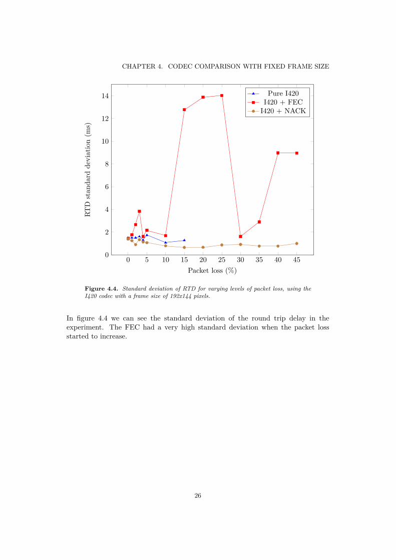
Figure 4.4. Standard deviation of RTD for varying levels of packet loss, using theI420 codec with a frame size of 192x144 pixels.
In figure 4.4 we can see the standard deviation of the round trip delay in theexperiment. The FEC had a very high standard deviation when the packet lossstarted to increase.
26
4.1. RESULTS
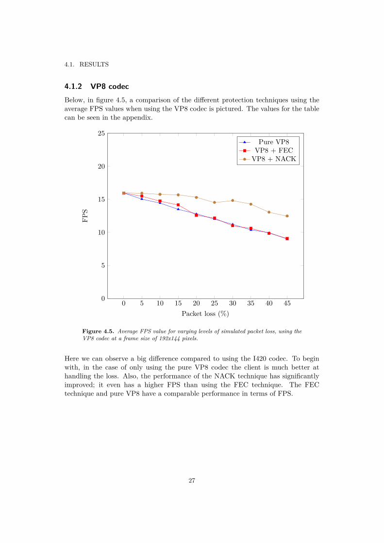
4.1.2 VP8 codecBelow, in figure 4.5, a comparison of the different protection techniques using theaverage FPS values when using the VP8 codec is pictured. The values for the tablecan be seen in the appendix.
0 5 10 15 20 25 30 35 40 450
5
10
15
20
25
Packet loss (%)
FPS
Pure VP8VP8 + FECVP8 + NACK
Figure 4.5. Average FPS value for varying levels of simulated packet loss, using theVP8 codec at a frame size of 192x144 pixels.
Here we can observe a big difference compared to using the I420 codec. To beginwith, in the case of only using the pure VP8 codec the client is much better athandling the loss. Also, the performance of the NACK technique has significantlyimproved; it even has a higher FPS than using the FEC technique. The FECtechnique and pure VP8 have a comparable performance in terms of FPS.
27
CHAPTER 4. CODEC COMPARISON WITH FIXED FRAME SIZE
0 5 10 15 20 25 30 35 40 450
0.5
1
1.5
2
2.5
3
3.5
4
Packet loss (%)
FPSstan
dard
deviation
Pure VP8VP8 + FECVP8 + NACK
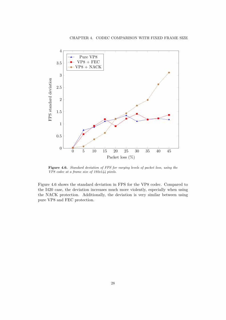
Figure 4.6. Standard deviation of FPS for varying levels of packet loss, using theVP8 codec at a frame size of 192x144 pixels.
Figure 4.6 shows the standard deviation in FPS for the VP8 codec. Compared tothe I420 case, the deviation increases much more violently, especially when usingthe NACK protection. Additionally, the deviation is very similar between usingpure VP8 and FEC protection.
28

4.2. ANALYSIS
0 5 10 15 20 25 30 35 40 450
10
20
30
40
50
60
70
80
90
Packet loss (%)
Rou
ndtrip
delay(ms)
Pure VP8VP8 + FECVP8 + NACK
Figure 4.7. Round trip delay for varying levels of packet loss, using the VP8 codecat a frame size of 192x144 pixels.
As we can see in figure 4.7, the increased levels of packet loss seems to have anegligible effect on the amount of delay when using the VP8 codec. While the pureVP8 and the NACK technique both still have the same low delay, the FEC delayalso has been reduced compared to the I420 case. The standard deviation in theRTD was less than 2 milliseconds in all cases.
4.2 AnalysisThe results from the first experiment shows a clear difference in FPS performance.When using no protection at all, the I420 codec is very sensitive even to minimalamounts of packet loss. This is most likely caused by the ineffectiveness of theI420 codec. Since if any packet belonging to a frame is lost, the frame will beincomplete, and thus not rendered, according to the method for the experiment.For example, if a 192x144 wide frame is encoded in YUV 4:2:0 format, 41472 Bytesis required. Assuming a packet size of 1500 bytes, a single frame would requireapproximately 28 packets to be transmitted without error. A 99 % chance that anypacket arrives correctly means that 28 packets arriving correctly has a probabilityof 0.9928 ∗ 100 ≈ 75%, and at 5 % packet loss, the probability drops down to 23 %.
29

CHAPTER 4. CODEC COMPARISON WITH FIXED FRAME SIZE
Interestingly, enabling the NACK protection provides an even worse perfor-mance than using pure I420. The cause behind this could be that when the NACKprotection is enabled, the client needs to buffer the frames for a little bit longer,in order to have enough time to resend a packet if it is lost, which means that themargins will decrease at the point where the client needs to decide if it has enoughtime to render the frame. Whenever a packet is lost, the total time before the packetarrives safely is at least doubled when the retransmission occurs, but could be evenlonger if the same packet is lost several times.
The effect of retransmitting a packet won’t affect the value of the RTD sincethe actual network parameters aren’t changed, even though the perceived delay isincreased. This is due to the NACK protection requiring relatively little bandwidthcompared to the FEC protection. Unfortunately, it is quite difficult to measure theactual perceived delay in this experiment without making significant changes to thecode.
Enabling the FEC protection does however increase the performance of the codecby a considerable amount. The FEC protection is able to maintain the FPS rate,even at relatively high levels of packet loss. At the point of 15 % packet loss, thetechnique is no longer able to withstand the loss, the FPS starts the drop, and thestandard deviation starts to increase. The reason behind this could be the limitationin bandwidth for the client. Since the FEC is limited to use at most 50 % of theavailable bandwidth, there will be a point where the bandwidth is just not enoughfor sending all the redundant data. Sending just the basic video stream requiresat least 4800 kbit/s, adding a 50 % overhead from FEC means that 7200 kbit/s isrequired. As the packet loss increases, so does the processing requirements of theclient. Assuming a packet size of 1500 bytes, a bitrate of 7200 kbit/s means that900 packets needs to be processed and sent every second. Since the client is alsoreceiving video, the number of packets is doubled to 1800 packets/second, and alsoneed to do audio processing and sending separately from the video.
Another indication that the client is starting to reach the processing limit is thechange in RTD. When the packet loss reaches 15 %, the RTD increased dramaticallyduring the experiment. This is probably due to the immense amount of traffic thatneeds to be processed and sent over the connection. If the client tries to send toomuch data, the client will not be able to process the packets fast enough, and thedelay might be affected. The amount of delay is still within the limits of what canbe noticed by a user (see section 2.1.2), but on a long distance link where the basedelay is much higher, it might seem more significant.
In summary, the I420 has very high bandwidth requirements, and using theFEC protection means that the requirements increase even further. Using NACKprotection does not seem to provide any improvement for the codec.
The VP8 codec on the other hand, performed much better during the experi-ment. Even without any protection, the codec is able to maintain the FPS relativelywell. The reason behind this is most likely the compression algorithms in the codecthat greatly reduces the number of packets needed for one frame. Some samplingof the frames revealed that an I-frame is about 5 packets and a P-frame is about
30

4.3. CONCLUSIONS
1-3 packets, a big difference compared to the 28 packets needed for the I420 codec.This also means that the probability of a frame arriving correctly is increased. AnI-frame has a 0.995 ∗ 100 ≈ 95% probability of arriving correctly, and a P-frame hasa 97-99 % probability.
Enabling the NACK protection also had a very different effect. In the I420 case,NACK protection performed worse than using no protection at all, but in the VP8case, NACK protection had one of the best results. Below 15 % packet loss, theFPS was almost completely unaffected.
The NACK protection for the VP8 codec also seemed to have very little effecton the measured RTD in the experiment. There was however a noticeable changein the perceived delay in the video, similar to the I420 case. The reason that theNACK protection performed much better in the VP8 case could also be contributedto the reduced number of packets needed for a frame.
The FEC protection also performed quite well in the experiment, although notas well as the NACK protection in this case. The FEC protection also only improvedthe FPS for packet loss less than 15 %. Above 15 %, the FEC protection did notprovide any significant gain in FPS.
The reason that the FEC protection performed worse than the NACK protectionis probably the computational cost of performing the FEC encoding and decoding.Whereas NACK is a relatively simple operation, the packets simply needs to bemarked for NACKing, FEC needs to perform many more operations when creatingthe FEC packets and trying to recover the media packets. Since the FEC protectionfor the I420 codec also started to perform worse at packet loss levels above 15 %, itseems like there is a certain limit where the FEC protection becomes inadequate,regardless of the codec used.
None of the protection modes seemed to have any effect on the RTD in theexperiment. This is probably due to the bandwidth requirements being low enough,even in the FEC case. Lets say that when sending VP8 encoded video at 15 FPS,2 frames are I-frames and 13 frames are P-frames. This means that on average,about 36 packets needs to be sent each second, and with a packet size of 1500 bytes,approximately 420 kbit/s is needed. Adding in the 50 % overhead from FEC, amaximum of about 630 kbit/s is needed when using FEC protection. Compared tothe I420 codec, the VP8 codec requires almost 10 times less bandwidth.
4.3 Conclusions
The VP8 codec outperformed the I420 codec on all accounts in the experiment. Itmanaged to keep the FPS consistent up until about 15 % packet loss, without hav-ing any significant gain in RTD. It also requires much less bandwidth to use. Theonly factor that might actually favor the I420 codec is the actual picture quality.Since the I420 codec does not compress the video at all, if no loss occurs the ren-dered video will have excellent quality. The VP8 codec on the other hand performsvarious compression techniques to reduce the size of the frames. This might lead to
31

CHAPTER 4. CODEC COMPARISON WITH FIXED FRAME SIZE
compression noise artifacts in the rendered video.As such, one should not completely dismiss the I420 codec. It could be useful
in a setting where a degraded video quality is intolerable, and a large amount ofbandwidth is available. In the case of video conversations on mobile phones, this isdefinitely not the case in this moment of time, and therefore the VP8 codec shouldbe used in favour of the I420 codec. The VP8 codec greatly reduces the numberof packets that needs to be sent, which suits the low-bandwidth conditions oftenpresent in mobile video conversations (see section 2.4.1).
32

Chapter 5
Protection comparison with varyingframe size
This chapter contains the result, the analysis, and the conclusions that could bedrawn from the second experiment; the comparison of the protection techniques forvarious frame sizes.
5.1 ResultsIn figure 5.1 we can see the comparison between different frame sizes for the VP8codec without any protection technique enabled.
Without any protection enabled, the FPS dropped linearly. The frame sizes352x288 and 480x360 had very similar performance during the experiment, and theframe size 640x480 performed significantly worse than the other frame sizes.
Figure 5.2 shows the comparison between different frame sizes for the VP8 codecwith the NACK protection enabled.Here we can see that the NACK protection tends to have a distinct limit where theperformance decreases very quickly, which can be seen by the cliffs in the figure.Similar to the case without any protection; the 640x480 frame size has a much worseperformance than the other sizes.
33

CHAPTER 5. PROTECTION COMPARISON WITH VARYING FRAME SIZE
0 10 20 30 400
5
10
15
20
25
Packet loss (%)
FPS
192x144352x288480x360640x480
Figure 5.1. Average FPS value for varying levels of frame size and simulated packetloss, using the VP8 codec without any protection technique.
34

5.1. RESULTS
0 10 20 30 400
5
10
15
20
25
Packet loss (%)
FPS
192x144352x288480x360640x480
Figure 5.2. Average FPS value for varying levels of frame size and simulated packetloss, using the VP8 codec with the NACK protection.
35

CHAPTER 5. PROTECTION COMPARISON WITH VARYING FRAME SIZE
Figure 5.3 shows the comparison between different frame sizes for the VP8 codecwith the FEC protection enabled.
0 10 20 30 400
5
10
15
20
25
Packet loss (%)
FPS
192x144352x288480x360640x480
Figure 5.3. Average FPS value for varying levels of frame size and simulated packetloss, using the VP8 codec with the FEC protection.
With the FEC protection enabled, the VP8 codec managed to handle all framesizes quite well. Interestingly, the larger sizes of 352x288 and 480x360 performedbetter than the smaller 192x144 in this experiment. Strangely enough, at the size of640x480 the FEC protection seemed to perform better as the packet loss increased.The 640x480 frame size still performed much worse than the other sizes.
5.2 Analysis
Without any protection enabled, the performance deteriorated quickly with increas-ing frame size. The NACK protection provided a very consistent protection, it per-formed well up to a certain level of packet loss but then the performance degradedrapidly. The reason behind this sudden drop in recovery probably lies in the verynature of the NACK technique.
Firstly, since the NACK of the lost packet occurs over the same link where thepacket was lost, there is a risk that the NACK packet is also lost, as well as theretransmitted packet. This means that at for example 20 % packet loss, a lostpacket only has 0.8 ∗ 0.8 ∗ 100 = 64% chance of being NACKed correctly.
36

5.3. CONCLUSIONS
Secondly, since the NACK technique needs to keep a history of all the packetsthat has been NACKed in order to know what packets to wait for before renderinga frame, the technique has a limit to the number of packets that can be NACKed.When this limit is reached, which turned out to be at 60 packets in the WebRTClibrary, more packets simply cannot be NACKed, which could cause the quick dropsin FPS that can be seen in figure 5.2.
The FEC protection did not have the same steep drops in performance as theNACK protection. Instead, the performance generally started at a maximum anddropped slowly with increasing packet loss. The strange exception to this was the640x480 size which had an increase in performance when the packet loss increasedfrom 0 % to 5 %. The cause behind this is difficult to determine, but might becontributed to the computational overhead of the FEC technique is made used ofonly when packet loss is actually occurring.
Another strange exception is that both the 352x288 and the 480x360 sizes per-formed better than the 192x144 size. In general, one might think that a smallerframe size would always perform better than a larger frame size due to the reducedprocessing requirements of the smaller size. Instead, it seems that the FEC tech-nique performs better as the number of packets needed for a frame increases, whichcan also been seen in the first experiment when the I420 codec is used. This coulddue to the packet masks used in FEC not being designed to work optimally whichsuch a small number of packets. A VP8 P-frame at 192x144 pixels only takes upabout 1-3 packets. When the number of packets is this low, the number of FECpackets needs to be low as well in order to not excess the bandwidth limit. TheFEC packets can’t use more than 50 % of the bandwidth, which in turn means thatthere can’t be more than about 0.5-1.5 FEC packets on average for each frame.Thus, when the frame size increases, the number of FEC allowed FEC packets willincrease, and the protection can be better distributed across the packets.
5.3 Conclusions
The 480x360 frame size seems to be the best fit for being used in mobile conversa-tions. This frame size had a very good performance in the experiment both whenFEC and when NACK was used, and seems to provide a good trade-off betweenvideo quality and processing requirements.
When it comes to the choice between using the FEC or the NACK protection,FEC had the best FPS performance for the I420 codec, and NACK had the bestFPS performance for the VP8 codec and with smaller frame sizes in general. TheFEC did add some RTD, but only for high levels of packet loss. NACK on the otherhand did not change the RTD, but it did add some visual delay to the video, evenwhen the packet loss was very low. The NACK protection therefore has the biggestchance of giving a good result when the delay is low in the network, while the FECworks best when much bandwidth is available. In a mobile video conversation, delayis usually high and bandwidth low, so none of the protection methods is ideal in
37

CHAPTER 5. PROTECTION COMPARISON WITH VARYING FRAME SIZE
this case. The best solution would probably be to combine the two functions andswitch between them dynamically. NACK protection could then be used when thedelay is low enough, and the FEC protection when enough bandwidth is available. Afuture experiment might exist in trying to find a good accommodation for switchingbetween these two protection modes dynamically by continually measuring the RTDand maybe estimating the bandwidth available in the video conversation.
38

Chapter 6
Unequal error protection
This chapter contains the result, the analysis, and the conclusions that could bedrawn from the third experiment; the impact of enabling unequal error protectionfor FEC when using the VP8 codec.
6.1 Results
4 6 8 10 12 140
10
20
30
40
50
Packet loss (%)
Packetsrecoveredby
FEC
inpa
rtition
0(%
)
No UEPUEP
Figure 6.1. Average percentage of packets recovered by FEC in partition 0, usingvarious levels of packet loss.
39

CHAPTER 6. UNEQUAL ERROR PROTECTION
The results from the third experiment can be seen in figure 6.1. In general, enablingthe unequal error protection did indeed result in an increased protection for the firstpartition in each frame. The amount of packets recovered by FEC belonging to thefirst partition of the frame increased by up to 7 % for certain amounts of packetloss.
6.2 AnalysisEnabling the unequal error protection did provide a gain in the number of packetsrecovered in the first partition. However, the gain is only minimal in comparison,sometimes being less than 2 % The cause behind this can be contributed to severalobservations.
Firstly, the first partition of the codec is much smaller than the second partition.The relative sizes of the partitions varies in the codec, but in general, the firstpartition corresponds to about 20 % of the total frame.
Secondly, the packet masks used in the UEP assumes that the packet loss inthe network is normally distributed, and that the protection within frames is alsonormally distributed. The packet mask can be seen as function that takes thenumber of media packets to protect and the number of FEC packets available forprotection, and returns a packet mask that specifies which media packets should beprotected by which FEC packets.
The combination of these two observations means that a difference in the relativenumber of packets recovered in the partitions is very dependent on the number ofFEC packets available for protection. The number of FEC packets available isdynamically decided when the client is running, and depends on a number of thingslike current bitrate and FPS, which means that the recovery frequency can varygreatly. This can be confirmed by observing the standard deviation of the recoveryfrequency in table B.22. At certain times, the standard deviation was as high asalmost 4.5 %.
Since the uncertainty is relatively high in the experiment, it is difficult to drawany certain conclusions from the result. Enabling the UEP did however increasethe recovery frequency for all levels of packet loss in the experiment. Only in thecase of 6 % packet loss is there a statistically significant difference between the twotechniques. A clearer indication of the effectiveness of the UEP might be given ifit was possible to separate the cases were there are less FEC packets than what isneeded to protect all media packets. However, it was not possible to implement thisin the client due to time constraints.
6.3 ConclusionsEven though the standard deviation in the experiment was quite high, there wasone occurrence where the difference was statistically significant. The UEP didresult in more packets being recovered in the first partition of the frame, but only
40

6.3. CONCLUSIONS
marginally. It is possible to make further improvements to the UEP protection inorder to further demonstrate its effectiveness. For example, one might change thesize of the partitions so that the first partition is 50 % of the frame instead of 20%. This would be useful when using the YUV format, where the first 50 % of theframe corresponds to the Y channel. One could then have more protection for theY channel than the less important UV channels.
Another example of an improvement would be to implement new packet masksthat are designed to protect against burst errors, rather than normally distributederrors, and a greater protection to the beginning of a partition, rather than theprotection being normally distributed within the partition.
With these two improvements implemented, UEP protection would probablyhave a more eminent effect in the conducted experiments. Since the UEP in inits simplicity is just a re-prioritisation of the individual packet protection, it is notcostly to use and does not increase the required bandwidth, while still increasingthe perceived quality of the video.
To summarize, the UEP technique has a very great potential for increasing theperceived quality of the video, especially with the VP8 codec, even though theexperiment did not show any statistically significant gain in the recovery rate forall except one packet loss level.
41


Chapter 7
Finishing thoughts
In this chapter some general conclusions about the WebRTC library and somethoughts on other future experiments can be found.
7.1 Conclusions about the WebRTC library
The WebRTC library in general seems like a potential candidate for being usedfor mobile conversations. It provides an array of different quality-improving tech-niques, both for audio and video data. The library is not perfect yet, there weresome bugs discovered during the development process, but for the most part theperformance has been solid. The VP8 codec in particular works very well in a mo-bile environment. The performance on the iPhone 4 was acceptable at the lowestframe resolution, but on the iPhone 4S it could handle a bit bigger frame sizes.The evaluated protection techniques managed to handle relatively high levels ofpacket loss. A normally distributed packet loss of 15 % is quite high for a mobileconversation, but the techniques still managed to protect the packets at that level.
7.2 Where to go from here
Since the experiment environment had to be simplified in order to perform theexperiments, the protection techniques might behave differently in a more advancedenvironment. It would be interesting to create a network setup where the clientsconnect through a local gateway when speaking to each other, rather than doing aloopback call. The simulated packet loss would then be done at this gateway insteadof in the client. This would make it possible to add real bandwidth limitations to theclient so that the behaviour of the protection techniques could be analyzed duringthese conditions. It would also be interesting to be able to simulate both burst errorsand normally distributed errors between the clients, and implementing somethingthat randomizes the delay in the video. This would make the experiments mimic areal video conversation more closely.
43

CHAPTER 7. FINISHING THOUGHTS
The testing in this report has been done in order to try to measure the objectivequality of the video. Trying to measure the subjective quality, with for example auser survey where the users rate the quality of the video, would be an interestingcomplement to the objective measurements.
Another future experiment would be to find out the FPS limit that provides thebest trade-off between performance and visual quality for the different codecs. TheFPS limit used in the experiment was chosen arbitrarily to decrease the processingresources needed to capture and render the frames without decreasing the experiencetoo much.
It would also be nice to be able to get more finely grained information abouta packets position within a frame. At the moment, the only information availablewhen a packet is recovered by FEC is the number of the partition it belongs to. Ifthe packet position also was available, it would be possible to evaluate the effects ofchanging the packet mask to give more protection to the beginning of a partition.
44

Bibliography
[Abo] About.com. Codec - What is a Codec? http://desktopvideo.about.com/od/glossary/g/codec.htm (2012-03-28).
[Cla01] Alan Clark. Passive Monitoring for Voice Over IP Gateways. Telecom-munications Industry Association, TR41.4-01-02-068, 2001.
[DRT97] R. Dube, C.D. Rais, and S.K. Tripathi. Improving NFS performance overwireless links. Computers, IEEE Transactions on, 46(3):290 –298, mar1997.
[FBB01] Nick Feamster, Deepak Bansal, and Hari Balakrishnan. On the interac-tions between layered quality adaptation and congestion control for stream-ing video. In in 11th International Packet Video Workshop, 2001.
[Gar] Jason Garrett-Glaser. First Look: H.264 and VP8 Compared. http://x264dev.multimedia.cx/archives/486#more-486 (2012-05-10).
[GI] Google Inc. WebRTC. http://www.webrtc.org/ (2012-05-14).
[Har03] Dennis Hardman. Noise and Voice Quality in VoIP Environments. AgilentTechnologies, White Paper, 2003.
[iso05] ISO/IEC Standard for Information Technology - Telecommunications andInformation Exchange Between Systems - Local and Metropolitan AreaNetworks - Specific Requirements Part 11: Wireless LAN Medium AccessControl (MAC) and Physical Layer (PHY) Specifications (Includes IEEEStd 802.11, 1999 Edition; IEEE Std 802.11A.-1999; IEEE Std 802.11B.-1999; IEEE Std 802.11B.-1999/Cor 1-2001; and IEEE Std 802.11D.-2001).ISO/IEC 8802-11 IEEE Std 802.11 Second edition 2005-08-01 ISO/IEC8802 11:2005(E) IEEE Std 802.11i-2003 Edition, pages 1 –721, 2005.
[Li07] Adam Li. RTP Payload Format for Generic Forward Error Correction.RFC 5109, Internet Engineering Task Force, 2007.
[LPB02] Sanghoon Lee, M.S. Pattichis, and A.C. Bovik. Foveated video qualityassessment. Multimedia, IEEE Transactions on, 4(1):129 –132, mar 2002.
45

BIBLIOGRAPHY
[MN09] I.A. McDonald and R. Nelson. Application-level QoS: improving video con-ferencing quality through sending the best packet next. In Int. J. InternetProtocol Technology, Vol. 4, No. 1, 2009.
[NCS] NCS. Federal Standard 1037C. http://www.its.bldrdoc.gov/fs-1037/fs-1037c.htm (2012-05-15).
[Oze] Jan Ozer. VP8 vs. H.264. http://www.streamingmedia.com/conferences/west2010/presentations/SMWest-2010-H264-VP8.pdf(2012-05-10).
[Roa05] Adam Roach. A Negative Acknowledgement Mechanism for SignalingCompression. RFC 4077, Internet Engineering Task Force, May 2005.
[Sky] Skype. Skype coming to the iPhone on Verizon Wireless + new versionadds TV video calling support. http://blogs.skype.com/en/2011/02/iphone_verizon.html (2012-05-14).
[Ui] Unwired insight. Ofcom mobile broadband survey reveals cover-age and contention issues. http://www.unwiredinsight.com/2011/ofcom-mobile-broadband-survey-reveals-coverage-and-contention-issues(2012-05-10).
[Wal05] Theodore Wallingford. Switching to VoIP. O’Reilly, 2005.
[Wika] Wikipedia. 3G. http://en.wikipedia.org/wiki/3G (2012-02-08).
[Wikb] Wikipedia. 4G. http://en.wikipedia.org/wiki/4G (2012-02-08).
[Wikc] Wikipedia. Frame rate. http://en.wikipedia.org/wiki/Frame_rate(2012-05-10).
[Wikd] Wikipedia. Public switched telephone network. http://en.wikipedia.org/wiki/Public_switched_telephone_network (2012-02-27).
[Wike] Wikipedia. Quantization. https://en.wikipedia.org/wiki/Quantization_%28signal_processing%29 (2012-02-08).
[Win05] Stefan Winkler. Digital Video Quality: Vision Models and Metrics. JOHNWILEY & SONS, 2005.
[WSJ] Charles Wang, Dean Sklar, and Diana Johnson. Forward Error-CorrectionCoding. http://www.aero.org/publications/crosslink/winter2002/04.html (2012-02-15).
[You91] Richard Young. Oh say, can you see? The physiology of vision. GeneralMotors Research Labs., 1991.
46

Appendix A
Word list
• Chrominance - Represents color information in an image, usually usingcolor-difference components.
• FEC - Forward Error Correction, a method that adds redundancy to a streamin order to be able to repair errors.
• FEC packet - A packet containing data that is formatted using FEC.
• Luma - Luminance, represents the brightness in an image (the black andwhite).
• Media packet - A packet containing the raw, unprotected user data to trans-mit.
• MTU - Maximum Transmission Unit, the maximum size in bytes of a dataunit that can be sent over a particular protocol. Standard value in TCP is1,500 bytes.
• NACK - Negative Acknowledgment, a technique that adds functionality forretransmitting lost data.
• PSTN - Public switched telephone network, a network of telephone lines thatallows any two telephones in the world to connect to eachother.
• QoS - Quality of Service, aspects related to networks that can be used tomake statements about the guarantees of a service.
• RGB - An additive color model, represents colors using one red channel (R),one green channel (G) and one blue channel (B).
• RTD - Round-trip time (RTT) or Round-trip delay time (RTD), is the timeit takes for a message to be sent plus the time it takes to receive the acknowl-edgment of the sent message.
47

APPENDIX A. WORD LIST
• RTP - Real-time Transport protocol, the standard packet format for sendingaudio and video over IP networks.
• RTT - See RTD.
• TCP - Transmission Control Protocol, provides reliable, ordered delivery ofdata.
• UDP - User Datagram Protocol, provides unreliable, possibly unordered de-livery of data.
• VoIP - Voice over IP, a collection of techniques for delivering voice calls overIP networks.
• YUV - Similar to RGB, a format for representing colors. Has one lumachannel (Y) and two chrominance channels (UV).
48

Appendix B
Experiment data
B.1 I420 data
Table B.1. I420 FPS graph data. The table contains the average FPS recorded foreach level of packet loss.
Packet loss (%) I420 (FPS) I420 + FEC (FPS) I420 + NACK (FPS)0 15.964 15.930 15.9651 12.242 15.888 9.21522 8.56 15.865 5.28903 7.0209 15.945 3.2674 5.2748 15.939 2.18225 4.3907 15.919 1.436910 0.5406 15.942 0.127415 0.05229 15.937 020 0 15.827 025 0 15.111 030 0 13.619 035 0 10.841 040 0 7.2723 045 0 4.2176 0
49

APPENDIX B. EXPERIMENT DATA
Table B.2. I420 FPS standard deviation graph data. The table contains the standarddeviation of the FPS recorded for each level of packet loss.
Packet loss (%) I420 (FPS) I420 + FEC (FPS) I420 + NACK (FPS)0 0.019574 0.18583 0.018391 1.4350 0.25998 1.68172 1.5431 0.24721 1.47723 1.2447 0.2213 0.934864 1.0211 0.2209 0.789255 1.0137 0.2292 0.7560210 0.5214 0.24267 0.07001815 0.38277 0.18528 020 0 0.29227 025 0 0.62497 030 0 1.0054 035 0 1.2426 040 0 1.1985 045 0 1.1312 0
Table B.3. I420 round trip delay graph data. The table contains the average RTDin milliseconds recorded for each level of packet loss.
Packet loss (%) I420 (ms) I420 + FEC (ms) I420 + NACK (ms)0 39.562 40.212 39.2491 39.917 38.867 38.8642 39 40.706 38.7143 40.294 40.5 38.6524 39.778 40.250 38.8185 39.400 40.238 38.47110 39.500 38.882 38.03215 39.091 76.880 38.52020 39.417 68.571 38.14325 39.824 60.069 38.52930 39.938 39.800 38.21135 39.625 39.438 38.43340 39.917 50.560 38.37545 40.130 47.857 38.714
50
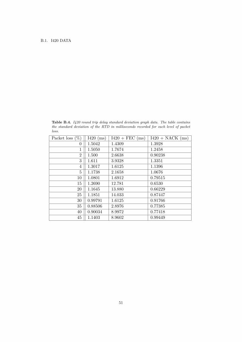
B.1. I420 DATA
Table B.4. I420 round trip delay standard deviation graph data. The table containsthe standard deviation of the RTD in milliseconds recorded for each level of packetloss.
Packet loss (%) I420 (ms) I420 + FEC (ms) I420 + NACK (ms)0 1.5042 1.4309 1.39281 1.5050 1.7674 1.24582 1.500 2.6638 0.902383 1.611 3.9328 1.33514 1.3017 1.6125 1.13965 1.1738 2.1658 1.067610 1.0801 1.6912 0.7951515 1.2690 12.781 0.653020 1.1645 13.880 0.6622925 1.1851 14.033 0.8744730 0.99791 1.6125 0.9176635 0.88506 2.8976 0.7738540 0.90034 8.9972 0.7741845 1.1403 8.9602 0.99449
51

APPENDIX B. EXPERIMENT DATA
B.2 VP8 data
Table B.5. VP8 average FPS at frame size 192x144 pixels. The table contains theaverage FPS recorded for each level of packet loss.
Packet loss (%) VP8 (FPS) VP8 + FEC (FPS) VP8 + NACK (FPS)0 15.965 15.961 15.9675 15.042 15.499 15.943
10 14.432 14.762 15.76515 13.495 14.176 15.67720 12.800 12.595 15.29925 12.026 12.167 14.54830 11.205 11.013 14.83235 10.378 10.614 14.27940 9.9304 9.8596 13.05745 8.9744 9.0678 12.484
Table B.6. VP8 standard deviation of FPS at frame size 192x144 pixels. The tablecontains the standard deviation of the FPS recorded for each level of packet loss.
Packet loss (%) VP8 (FPS) VP8 + FEC (FPS) VP8 + NACK (FPS)0 0.0207 0.015372 0.016705 0.74252 0.57614 0.076458
10 0.86394 0.91883 0.3679415 1.105 1.1930 0.6302720 1.1980 0.90509 1.208825 1.3453 1.2145 1.436030 1.1034 1.4156 1.752935 1.1886 1.1799 1.984140 1.2259 1.2293 2.2672845 1.1777 1.3703 3.1096
52

B.2. VP8 DATA
Table B.7. VP8 average RTD at frame size 192x144 pixels. The table contains theaverage round trip delay in milliseconds recorded for each level of packet loss.
Packet loss (%) VP8 (ms) VP8 + FEC (ms) VP8 + NACK (ms)0 39.312 39.390 39.7735 39.524 39.708 39.520
10 39.844 39.560 39.14315 40 39.524 39.90520 40.250 39.737 39.88225 40.421 39.750 39.41230 39.788 39.900 39.74335 40.105 39.875 39.17640 40.278 39.909 39.76545 39.941 40.235 39.741
Table B.8. VP8 standard deviation of RTD at frame size 192x144 pixels. The tablecontains the standard deviation of the round trip delay in milliseconds recorded foreach level of packet loss.
Packet loss (%) VP8 (ms) VP8 + FEC (ms) VP8 + NACK (ms)0 0.0207 0.01537 0.016705 0.74252 0.57614 0.07648
10 0.8639 0.91883 0.3679515 1.105 1.1930 0.6302720 1.198 0.90509 1.208825 1.3453 1.2145 1.436030 1.1034 1.4156 1.752935 1.1886 1.1799 1.984140 1.2259 1.2293 2.627845 1.1777 1.3703 3.1096
53

APPENDIX B. EXPERIMENT DATA
Table B.9. VP8 average FPS at frame size 352x288 pixels. The table contains theaverage FPS recorded for each level of packet loss.
Packet loss (%) VP8 (FPS) VP8 + FEC (FPS) VP8 + NACK (FPS)0 15.971 15.969 15.9945 14.356 15.880 15.966
10 13.024 15.572 15.91715 11.060 15.504 15.81220 10.088 15.141 15.64425 9.3658 15.130 15.79930 8.1465 14.404 15.55535 6.5529 13.683 15.26940 6.2280 13.000 10.51645 5.4160 11.975 1.1377
Table B.10. VP8 standard deviation of FPS at frame size 352x288 pixels. The tablecontains the standard deviation of the FPS recorded for each level of packet loss.
Packet loss (%) VP8 (FPS) VP8 + FEC (FPS) VP8 + NACK (FPS)0 0.66568 0.25013 0.208285 0.94324 0.19205 0.25253
10 0.98988 0.57309 0.2342115 1.0390 0.58063 0.4629420 1.2634 0.77265 0.7313325 1.1711 0.83053 1.188130 1.1204 0.96925 1.410835 0.95320 1.1111 2.097540 0.98491 1.1340 4.830945 1.3408 1.2473 1.4067
54
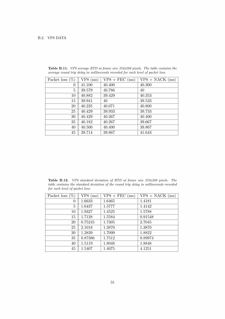
B.2. VP8 DATA
Table B.11. VP8 average RTD at frame size 352x288 pixels. The table contains theaverage round trip delay in milliseconds recorded for each level of packet loss.
Packet loss (%) VP8 (ms) VP8 + FEC (ms) VP8 + NACK (ms)0 41.100 40.400 40.3005 39.579 40.786 40
10 40.882 39.429 40.35315 39.941 40 39.53320 40.235 40.071 40.80025 40.429 39.933 39.73330 40.429 40.267 40.40035 40.182 40.267 39.66740 40.500 40.400 39.86745 39.714 39.867 41.643
Table B.12. VP8 standard deviation of RTD at frame size 352x288 pixels. Thetable contains the standard deviation of the round trip delay in milliseconds recordedfor each level of packet loss.
Packet loss (%) VP8 (ms) VP8 + FEC (ms) VP8 + NACK (ms)0 1.6633 1.6465 1.41815 1.6437 1.5777 1.4142
10 1.9327 1.4525 1.578815 1.7128 1.5584 0.9154820 0.75245 1.7305 2.704525 2.1018 1.3870 1.387030 1.2839 1.7099 1.882235 0.87386 1.7512 0.8997440 1.5119 1.8048 1.884845 1.5407 1.4075 4.1251
55

APPENDIX B. EXPERIMENT DATA
Table B.13. VP8 average FPS at frame size 480x360 pixels. The table contains theaverage FPS recorded for each level of packet loss.
Packet loss (%) VP8 (FPS) VP8 + FEC (FPS) VP8 + NACK (FPS)0 15.554 15.882 15.6225 14.082 15.780 15.629
10 12.659 15.923 15.33415 11.080 15.875 15.23120 10.260 15.514 14.92725 8.9379 15.204 14.92430 8.1428 14.835 9.686835 6.4641 13.891 0.1400340 5.7556 13.109 -45 - 11.953 -
Table B.14. VP8 standard deviation of FPS at frame size 480x360 pixels. The tablecontains the standard deviation of the FPS recorded for each level of packet loss.
Packet loss (%) VP8 (FPS) VP8 + FEC (FPS) VP8 + NACK (FPS)0 0.79244 0.71569 1.30665 0.94324 0.36205 0.68539
10 1.0141 0.27743 0.6075315 1.2751 0.40013 0.7496920 1.0004 0.47075 1.054725 1.6013 0.72025 1.696830 1.0211 0.74631 6.084635 1.3140 1.1953 0.03045140 1.2482 1.0777 -45 - 1.1215 -
56

B.2. VP8 DATA
Table B.15. VP8 average RTD at frame size 480x360 pixels. The table contains theaverage round trip delay in milliseconds recorded for each level of packet loss.
Packet loss (%) VP8 (ms) VP8 + FEC (ms) VP8 + NACK (ms)0 41.333 42.529 44.6005 42.733 41.294 43.733
10 41.357 41.800 46.37515 44.333 42.533 52.26720 42.429 42.471 49.50025 43.071 41.800 45.12530 40.933 42.600 56.86735 40.636 41.533 56.28640 41.429 40.933 -45 - 41.733 -
Table B.16. VP8 standard deviation of RTD at frame size 480x360 pixels. Thetable contains the standard deviation of the round trip delay in milliseconds recordedfor each level of packet loss.
Packet loss (%) VP8 (ms) VP8 + FEC (ms) VP8 + NACK (ms)0 2.8200 2.9816 4.18845 5.9217 2.2013 3.5750
10 2.5603 2.2424 6.621915 6.2412 2.8752 10.91220 3.8772 2.9605 10.64625 4.7953 2.0771 8.389530 2.2190 4.0497 17.21735 1.0269 3.0675 14.29640 2.9539 2.3442 -45 - 4.8028 -
57

APPENDIX B. EXPERIMENT DATA
Table B.17. VP8 average FPS at frame size 640x480 pixels. The table contains theaverage FPS recorded for each level of packet loss.
Packet loss (%) VP8 (FPS) VP8 + FEC (FPS) VP8 + NACK (FPS)0 9.5824 9.5233 10.0445 8.7666 11.865 0.43978
10 8.2688 12.541 -15 7.2255 12.399 -20 - 12.646 -25 - 12.525 -30 - 12.051 -35 - 11.554 -40 - 12.466 -45 - 11.543 -
Table B.18. VP8 standard deviation of FPS at frame size 640x480 pixels. The tablecontains the standard deviation of the FPS recorded for each level of packet loss.
Packet loss (%) VP8 (FPS) VP8 + FEC (FPS) VP8 + NACK (FPS)0 0.69191 0.81456 0.786585 0.80007 0.74171 0.48920
10 1.0179 0.64751 -15 1.0923 0.74399 -20 - 0.70772 -25 - 0.62402 -30 - 0.56725 -35 - 0.77876 -40 - 1.1648 -45 - 0.96084 -
58

B.2. VP8 DATA
Table B.19. VP8 average RTD at frame size 640x480 pixels. The table contains theaverage round trip delay in milliseconds recorded for each level of packet loss.
Packet loss (%) VP8 (ms) VP8 + FEC (ms) VP8 + NACK (ms)0 44.533 43.438 43.1255 62.733 42.588 37.312
10 68 43.400 -15 70.600 44.471 -20 - 45.867 -25 - 43.824 -30 - 44.500 -35 - 44.200 -40 - 42.933 -45 - 44.438 -
Table B.20. VP8 standard deviation of RTD at frame size 640x480 pixels. Thetable contains the standard deviation of the round trip delay in milliseconds recordedfor each level of packet loss.
Packet loss (%) VP8 (ms) VP8 + FEC (ms) VP8 + NACK (ms)0 4.5492 4.0820 4.34935 28.774 3.3922 10.058
10 26.093 3.0190 -15 46.153 5.9173 -20 - 4.2906 -25 - 6.2173 -30 - 3.7417 -35 - 6.8159 -40 - 5.7130 -45 - 6.7129 -
59

APPENDIX B. EXPERIMENT DATA
B.3 Unequal error protection data
Table B.21. UEP graph data for FEC packet recovery. The number in the last twocolumns is the percentage of packets recovered using FEC protection that belongs topartition 0 of the frame.
Packet loss (%) No UEP (%) UEP (%)4 19.183 21.0406 20.594 27.7238 26.843 30.84510 28.358 35.28412 30.755 35.05014 32.615 33.993
Table B.22. UEP standard deviation data for FEC packet recovery. The number inthe last two columns is the standard deviation of the percentage of packets recoveredusing FEC protection that belongs to partition 0 of the frame.
Packet loss (%) No UEP (%) UEP (%)4 1.9761 3.55156 2.8594 3.58238 2.1830 2.453610 4.4212 4.477912 3.1199 4.230014 3.5950 3.5238
60

TRITA-CSC-E 2012:043 ISRN-KTH/CSC/E--12/043-SE
ISSN-1653-5715
www.kth.se


![MODEL-BASED DESIGN, CONTROL AND OPTIMISATION OF … · the methyl acetate synthesis using Amberlyst 15W [19]. Own laboratory experiments were conducted to investigate the reaction](https://static.fdocuments.in/doc/165x107/5e45a969973756124429cc5d/model-based-design-control-and-optimisation-of-the-methyl-acetate-synthesis-using.jpg)


