
Experiments on Stabilization of the Hanging Equilibrium of a 3D Asymmetric Rigid...
6
Experiments on Stabilization of the Hanging Equilibrium of a 3D Asymmetric Rigid Pendulum Mario A. Santillo † , Nalin A. Chaturvedi † , Fabio Bacconi ‡ , N. Harris McClamroch † , Dennis Bernstein † † Department of Aerospace Engineering University of Michigan Ann Arbor, MI 48109 {santillo,nalin,nhm,dsbaero}@umich.edu ‡ Dipartimento di Sistemi e Informatica Universit` a degli Studi di Firenze Via S. Marta, 3 - 50139, Italy {bacconi}@control.dsi.unifi.it Abstract—We introduced a theory for stabilization of a 3D pendulum, consisting of a rigid body that is supported at a frictionless pivot, in a 2005 ACC paper. One of the controllers proposed in that paper, based on angular velocity feedback only, asymptotically stabilizes the hanging equilibrium of the pendulum. This paper continues this line of research, providing a description of an experimental setup and a sample of experimental results illustrating the closed loop properties of the 3D pendulum. Experimental results are discussed and compared with the theory presented in the previous paper. I. I NTRODUCTION Pendulum models have provided a rich source of examples that have motivated and illustrated many recent developments in nonlinear dynamics and in nonlinear control [1], [2]. Much of the published research treats 1D planar pendulum models or 2D spherical pendulum models or some multi- body version of these. In a recent paper [3], we summarized much of this published research, emphasizing papers that treat control issues. In addition, we introduced a new 3D pendulum model that, surprisingly, seems not to have been studied in the prior literature. Another overview of pendulum control problems was given in [2], which also provides motivation for the importance of such control problems. This paper provides experimental verification of stabilization results for a 3D asymmetric rigid pendulum presented in [4]. In [4], we studied stabilization problems for a 3D asym- metric rigid pendulum defined in terms of the reduced attitude. The reduced attitude is the attitude of the pendulum, modulo rotations about the vertical. In other words, two attitudes have identical reduced attitudes if they differ only by a rotation about the vertical. A 3D rigid pendulum is supported at a pivot. The pivot is assumed to be frictionless and inertially fixed. The rigid body is asymmetric and the location of the center of mass is distinct from the location of the pivot. Forces that arise from uniform and constant gravity This research has been supported in part by NSF under grant ECS- 0140053 and grant ECS-0244977. act on the rigid body. Three independent control moments are assumed to act on the rigid body. In this paper, experiments verify the stabilization theory presented in [4]. We follow the development and notation introduced in [3]. In particular, the formulation of the model depends on construction of a Euclidean coordinate frame fixed to the rigid body with origin at the pivot and an inertial Euclidean coordinate frame with origin at the pivot. Without loss of generality, we assume that the inertial coordinate frame is selected so that the first two axes lie in a horizontal plane and the “positive” third axis points down. The relevant mathematical model is expressed in terms of the angular velocity vector and the reduced attitude vector of the rigid body. The reduced attitude vector is a unit vector in the direction of gravity, expressed in the body fixed coordinate frame. The control problem treated in this paper is asymp- totic stabilization of an equilibrium of the 3D pendulum defined by zero angular velocity and a reduced attitude vector that corresponds to the hanging equilibrium configuration. The Triaxial Attitude Control Testbed (TACT) has been described in detail in [5] with mathematical models given in [6]. This paper includes a description of the specific experimental setup of the TACT, the measurement system, and the attitude estimation algorithm. Experimental results for closed-loop responses are presented. The discussion ties these results to the theory presented in [4]. The main contribution of this paper is its summary and experimental verification of results for asymptotic stabiliza- tion of the hanging equilibrium of a 3D asymmetric rigid pendulum. These results provide near-global asymptotic sta- bilization in a direct way using a single nonlinear controller. II. SUMMARY OF STABILIZATION RESULTS In this section, we review the control model introduced in [4], assuming full control actuation. We present appropriate Proceedings of the 2005 IEEE Conference on Control Applications Toronto, Canada, August 28-31, 2005 MB4.5 0-7803-9354-6/05/$20.00 ©2005 IEEE 308
-
Upload
trinhhuong -
Category
Documents
-
view
217 -
download
3
Transcript of Experiments on Stabilization of the Hanging Equilibrium of a 3D Asymmetric Rigid...
Experiments on Stabilization of the Hanging Equilibriumof a 3D Asymmetric Rigid Pendulum
Mario A. Santillo†, Nalin A. Chaturvedi†, Fabio Bacconi‡,N. Harris McClamroch†, Dennis Bernstein†
†Department of Aerospace EngineeringUniversity of MichiganAnn Arbor, MI 48109
{santillo,nalin,nhm,dsbaero}@umich.edu
‡Dipartimento di Sistemi e InformaticaUniversita degli Studi di Firenze
Via S. Marta, 3 - 50139, Italy{bacconi}@control.dsi.unifi.it
Abstract— We introduced a theory for stabilization of a3D pendulum, consisting of a rigid body that is supportedat a frictionless pivot, in a 2005 ACC paper. One of thecontrollers proposed in that paper, based on angular velocityfeedback only, asymptotically stabilizes the hanging equilibriumof the pendulum. This paper continues this line of research,providing a description of an experimental setup and a sampleof experimental results illustrating the closed loop propertiesof the 3D pendulum. Experimental results are discussed andcompared with the theory presented in the previous paper.
I. INTRODUCTION
Pendulum models have provided a rich source of examplesthat have motivated and illustrated many recent developmentsin nonlinear dynamics and in nonlinear control [1], [2].Much of the published research treats 1D planar pendulummodels or 2D spherical pendulum models or some multi-body version of these. In a recent paper [3], we summarizedmuch of this published research, emphasizing papers thattreat control issues. In addition, we introduced a new 3Dpendulum model that, surprisingly, seems not to have beenstudied in the prior literature. Another overview of pendulumcontrol problems was given in [2], which also providesmotivation for the importance of such control problems.This paper provides experimental verification of stabilizationresults for a 3D asymmetric rigid pendulum presented in [4].
In [4], we studied stabilization problems for a 3D asym-metric rigid pendulum defined in terms of the reducedattitude. The reduced attitude is the attitude of the pendulum,modulo rotations about the vertical. In other words, twoattitudes have identical reduced attitudes if they differ onlyby a rotation about the vertical. A 3D rigid pendulum issupported at a pivot. The pivot is assumed to be frictionlessand inertially fixed. The rigid body is asymmetric and thelocation of the center of mass is distinct from the location ofthe pivot. Forces that arise from uniform and constant gravity
This research has been supported in part by NSF under grant ECS-0140053 and grant ECS-0244977.
act on the rigid body. Three independent control momentsare assumed to act on the rigid body.
In this paper, experiments verify the stabilization theorypresented in [4]. We follow the development and notationintroduced in [3]. In particular, the formulation of the modeldepends on construction of a Euclidean coordinate framefixed to the rigid body with origin at the pivot and an inertialEuclidean coordinate frame with origin at the pivot. Withoutloss of generality, we assume that the inertial coordinateframe is selected so that the first two axes lie in a horizontalplane and the “positive” third axis points down. The relevantmathematical model is expressed in terms of the angularvelocity vector and the reduced attitude vector of the rigidbody. The reduced attitude vector is a unit vector in thedirection of gravity, expressed in the body fixed coordinateframe. The control problem treated in this paper is asymp-totic stabilization of an equilibrium of the 3D pendulumdefined by zero angular velocity and a reduced attitude vectorthat corresponds to the hanging equilibrium configuration.
The Triaxial Attitude Control Testbed (TACT) has beendescribed in detail in [5] with mathematical models givenin [6]. This paper includes a description of the specificexperimental setup of the TACT, the measurement system,and the attitude estimation algorithm. Experimental resultsfor closed-loop responses are presented. The discussion tiesthese results to the theory presented in [4].
The main contribution of this paper is its summary andexperimental verification of results for asymptotic stabiliza-tion of the hanging equilibrium of a 3D asymmetric rigidpendulum. These results provide near-global asymptotic sta-bilization in a direct way using a single nonlinear controller.
II. SUMMARY OF STABILIZATION RESULTS
In this section, we review the control model introduced in[4], assuming full control actuation. We present appropriate
Proceedings of the2005 IEEE Conference on Control ApplicationsToronto, Canada, August 28-31, 2005
MB4.5
0-7803-9354-6/05/$20.00 ©2005 IEEE 308

definitions as background for the control experiments. Inthe following sections, we present a description of theexperimental testbed, and we discuss experimental results forasymptotic stabilization of the hanging equilibrium, based onfeedback of the angular velocity.
As shown in [3], the control model for the fully actuated3D asymmetric rigid pendulum is given by{
Jω = Jω × ω + mgρ × Γ + u,
Γ = Γ × ω,(1)
where, ω ∈ R3 represents the angular velocity of the rigid
body, Γ ∈ S2 represents the reduced attitude vector, andu ∈ R
3 is the control input. The reduced attitude vector isa unit vector in the direction of gravity in the body-fixedframe. The reduced attitude is the complete attitude, modulorotations about the vertical. Here J is the inertia matrix of therigid 3D pendulum, m is its total mass, ρ is the vector fromthe pivot to the center of mass in the body-fixed coordinateframe, and g is the constant acceleration of gravity. Thehanging equilibrium of the uncontrolled pendulum is denotedby Γh = ρ
‖ρ‖ .
As presented in [3], the hanging equilibrium of the uncon-trolled pendulum is locally stable in the sense of Lyapunov. Asimple controller is developed in [4] that makes the hangingequilibrium asymptotically stable. The controller is based onthe observation that the control model given by equation (1)is input-output passive if the angular velocity is taken asthe output. The total energy is the storage function. Sincethe total energy, 1
2 ωTJω − mgρTΓ, has a minimum at thehanging equilibrium (0, Γh), a control law based on angularvelocity feedback is natural.
Let Ψ : R3 �→ R
3 be a smooth function such that
ε1‖x‖2 ≤ xTΨ(x) ≤ ε2‖x‖2, ∀x ∈ R3, (2)
where ε2 ≥ ε1 > 0. We propose a class of controllers,referred to as damping injection controllers, given by
u = −Ψ(ω), (3)
where Ψ(·) satisfies (2). It was shown in [4] that theabove family of controllers, which requires only angularvelocity feedback, renders the hanging equilibrium of a 3Dasymmetric pendulum asymptotically stable. For any ε > 0,a guaranteed domain of attraction H is given by
H ={
(ω, Γ) ∈ R3 × S2 :
12ωTJω
+12mg‖ρ‖ (Γ − Γh)T (Γ − Γh) ≤ 2mg‖ρ‖ − ε
}.
(4)
The controller (3) is traditional in that it exploits passivityto inject damping. However, the controller cannot provideglobal asymptotic stability due to a fundamental topologicallimitation that arises from the fact that the configuration
space S2 is compact. The set described in (4) providesa conservative domain of attraction. As shown in [4], themaximal domain of attraction is in fact R
3 × S2, except fora set of Lebesgue measure zero. Note that it does not containthe inverted reduced equilibrium (0,Γi), where Γi = −ρ
‖ρ‖ .
III. TRIAXIAL ATTITUDE CONTROL TESTBED (TACT)
The experimental facility, located in the Attitude Dynam-ics and Control Laboratory at the University of Michigan, isreferred to as the Triaxial Attitude Control Testbed (TACT).The TACT consists of a rotational platform, supported bya triaxial air bearing, which allows nearly unrestricted threedegrees of rotational motion. Control actuators and instru-mentation are mounted to the platform. Computer and com-munications systems are available for data acquisition, testoperations, and post-test processing. The physical features ofthe TACT have been described in [5]. A picture of the TACTis provided in Figure 1.
Fig. 1. Triaxial Attitude Control Testbed (TACT)
Fan thrusters are rigidly attached to the platform andprovide control actuation for the TACT. These thrustersoperate on ±24 VDC and are open-loop speed controlled.A total of four thrusters are mounted to a square outer plateon the TACT, equidistant from the roll axis. Two thrustersprovide direct actuation about the yaw axis, while the othertwo provide actuation about the pitch axis. Combining onefrom each group provides actuation about the roll axis. Eachfan motor is driven by a current-regulated PWM amplifier.Electric power is supplied from a series of 12-V lead acidbatteries. Details of the thrusters’ construction and specifica-tions can be found in [5]. A closer picture of the fan thrusterson the TACT is provided in Figure 2.
A triaxial accelerometer is mounted to the TACT andaligned with the body-fixed axes. Before each test, theaccelerometer triad must be calibrated to read 1-g on eachindividual axis when aligned with the downward vertical. Todo this, the TACT is rotated about each axis independently
309

Fig. 2. Fan Thruster Assembly on TACT
while taking continuous readings from the accelerometers.The accelerometer axis is defined to be aligned with thedownward vertical when a maximum occurs in the data.Bias and scaling factors are then adjusted such that eachaccelerometer outputs 1-g at this maximum point.
We are able to estimate the reduced attitude using ac-celerometers and gyros fixed to the platform. We computethe acceleration due to gravity; this leads directly to thereduced attitude. Since the accelerometer triad is not attachedat the pivot point, the accelerometers measure not only theacceleration of gravity, but also angular and centripetal ac-celeration terms. Centripetal acceleration can be determinedindirectly by using the knowledge of the angular velocity.We thus use a triaxial gyro to measure angular velocity andto compensate for the effects of centripetal acceleration. Theangular acceleration term is ignored in the computation ofthe reduced attitude, but preliminary calculations suggest thatits contribution is quite small.
An embedded processor is used for real-time on-boardprocessing. This processor is based on a 486 chipset with4 GB solid state hard disk and three Multi-Q I/O boardsallowing 24 A/D channels, 24 D/A channels, and 24 encoderchannels. A host PC, which is detached from the TACT,communicates with the testbed through a wireless ethernetconnection. This communication is required for experimentmonitoring and data acquisition. Software controllers aredeveloped on the host PC using Simulink and then uploadedto the on-board processor for experimentation.
The TACT allows us to study a wide variety of pendulumproblems. Since the system’s center of gravity is not locatedat the pivot point, the TACT behaves like a 3D pendulum. Aschematic of a 3D rigid pendulum is provided in Figure 3.
IV. TACT CLOSED LOOP STABILIZATION EXPERIMENTS
In this section we summarize experimental protocols andresults that demonstrate the controller given in (3) asymp-totically stabilizes the hanging equilibrium based on angular
XY
Z
X’
Y’
g
o
Z’ ρCG
.
.
.
.
Fig. 3. Schematic of a Rigid Pendulum
velocity feedback alone. The controller used for this purposewas chosen such that Ψ(ω) = −Pω, where P = 10I3. Thischoice of equal gains in the three feedback channels does notrepresent a particularly effective choice in terms of closed-loop performance. However, our objective in the experimentsis to demonstrate closed-loop stabilization; we did not seekto tune the gains to achieve closed-loop performance.
A brief description of the experimental procedure ispresented. For each of the stabilization experiments, thecontroller is first developed on the host PC and then uploadedto the on-board processor via wireless ethernet. Real-timeplots are created on the host PC for experiment monitoring.The pendulum is released from its initial conditions, asdescribed below for each case, and the controller is acti-vated to stabilize the pendulum to the hanging equilibrium.Important data is continuously transferred over the wirelessethernet to the host PC for experiment monitoring and post-test processing.
The aim of these experiments is to verify and supportthe theory presented in [4]. With that in mind, we reportthree experiments that encompass several different initialangular velocities and pendulum configurations. The first twoexperiments verify that when starting inside the domain ofattraction, the pendulum remains inside that set and it isattracted to the hanging equilibrium; initial conditions werechosen to start within the guaranteed domain of attraction.The third experiment verifies that even when starting outsidethe computable domain of attraction, the pendulum eventu-ally enters this set and is attracted to the hanging equilibrium.These initial conditions were chosen to excite all degreesof freedom of the system. The set given in (4) is only anestimate of the domain of attraction. It is possible that theinitial conditions in the third experiment are outside the setH, but still within the actual domain of attraction.
Each experiment involves large perturbations from thehanging equilibrium. Time response plots of both the angularvelocity vector and the reduced attitude vector are providedfor each case. The TACT was set up so that the reducedhanging equilibrium is given by Γh = ρ
‖ρ‖ = (0, 0, 1)T in
310

the body fixed coordinate frame.
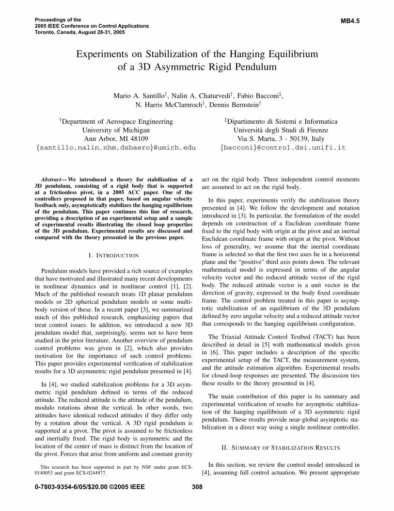
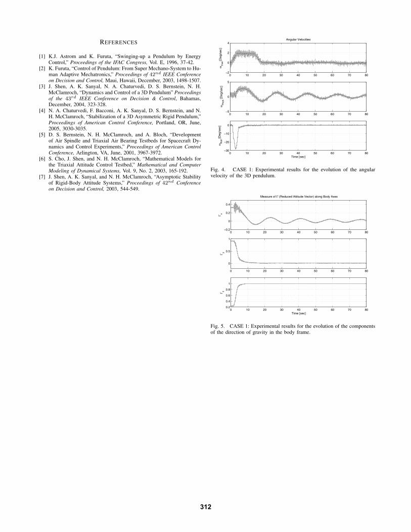
For the first experiment, the 3D pendulum was releasedwith an initial attitude Γ = (0.35, 0.90, 0.25)T and zeroangular velocity. The controller was activated to stabilizethe pendulum to the hanging equilibrium. As seen fromexperimental closed loop responses shown in Figures 4 and5, the angular velocity converges to zero and Γ(t) convergesto Γh = (0, 0, 1)T as t → ∞.
For the second experiment, the 3D pendulum was releasedfrom the hanging equilibrium position with angular velocityω = (0, 0, 40)T deg/s. The controller was activated to returnthe pendulum to the hanging equilibrium. As seen fromexperimental closed loop responses shown in Figures 6 and7, the angular velocity converges to zero and Γ(t) convergesto Γh = (0, 0, 1)T as t → ∞.
For the third experiment, the 3D pendulum was releasedfrom an initial attitude Γ = (−0.25,−0.20, 0.95)T andangular velocity ω = (−30,−5,−15)T deg/s. The controllerwas activated to stabilize the pendulum to the hanging equi-librium. As seen from experimental closed loop responsesshown in Figures 8 and 9, the angular velocity converges tozero and Γ(t) converges to Γh = (0, 0, 1)T as t → ∞.
The fan thrusters provide approximately 5 N-m of controlauthority in each axis. Thruster saturation can be an issue inthese control experiments and the feedback gains need to bereviewed to minimize any nonlinearities arising from satura-tion. This will become critical in future control experimentsthat seek to asymptotically stabilize the inverted equilibriumusing controllers presented in [4].
It can be seen that a residual damped oscillation remainsin the pitch axis angular velocity for each of the experiments.Carefully adjusting the feedback control gains for each axisis expected to compensate for the oscillation. It is also notedthat measurements during the initial transient period areespecially noisy. This can be attributed to both gyro noiseand an attitude estimation algorithm that ignores angularacceleration, which can add to noisy measurements duringthe initial transient period. To minimize estimation errors,gyro biases were adjusted before each experiment since anyadditional offset in these sensors would show up in theattitude estimation algorithm through the angular velocityterms.
All three experiments verify the theory of asymptoticstabilization presented in [4]. Initial conditions chosen bothinside and outside the computable domain of attraction (4)all exhibit rapid convergence to the hanging equilibrium.Comparing the results, it is seen that initial perturbationsin the yaw angular velocity leads to slow pitch angle con-vergence; the nonlinear coupling is small in this case. Also,initial perturbations that excite all degrees of freedom lead torelatively faster convergence; the nonlinear coupling is largein this case.
V. CONCLUDING REMARKS
In this paper we present experimental results that verify thestabilization of the hanging equilibrium for the asymmetric3D rigid pendulum. We discuss the experimental setup, themeasurement system and the attitude estimation algorithmthat are crucial to the experiments. We study a controller,based on feedback of angular velocity only, that asymptoti-cally stabilizes the hanging equilibrium. Experimental resultsare provided to illustrate the closed loop properties of the 3Dpendulum system.
We have demonstrated the simplicity of the control imple-mentation for the feedback controller. The simple dampinginjection controller has proven to asymptotically stabilize thehanging equilibrium of the 3D pendulum. This paper justifiesthe importance of theory as a guide for new nonlinear controlexperiments. These experiments are an invaluable tool thatallow us to asses the practical value of theoretical controlresults, identify new control problems and new applications,and establish the need for new theoretical results.
The experiments reported herein describe our first exper-iments carried out on reduced attitude stabilization. Theseinitial closed-loop experiments have taught us several im-portant lessons. The robustness of the TACT and associatedinstrumentation is crucial for experimental accuracy and re-peatability. Angular velocity estimates, obtained from gyros,are sufficiently accurate for our purposes, but additionalattention needs to be given to estimation of the reducedattitude. Control saturation effects need to be analyzed andassessed in future control experiments. As with many phys-ical systems such as the TACT, integration and implemen-tation of complex hardware and software packages requiresmuch care and tuning to provide results in an accurate andmeaningful manner. These lessons should prove valuable aswe continue our experimental research on stabilization of the3D pendulum.
Several next steps in experimentation are proposed forfuture research with the TACT. Feedback controllers utilizingthe reduced attitude are of immediate concern. This requiresthe use of an on-board attitude estimation algorithm, similarto what is currently used in the post-processing proce-dure. By incorporating 3-axis magnetometer measurementsto distinguish between rotations about the vertical, we canutilize feedback controllers that require estimation of thecomplete attitude. Stabilization of the inverted equilibriumhas yet to be demonstrated by experimentation on the TACT,based on controller designs presented in [4]. One furtherassumption of this paper is full control actuation. Controllerscan be developed to stabilize an equilibrium in the case ofunderactuation; see for example [7]. These should be studied,as well, by experiments on a TACT implementation.
311
REFERENCES
[1] K.J. Astrom and K. Furuta, “Swinging-up a Pendulum by EnergyControl,” Proceedings of the IFAC Congress, Vol. E, 1996, 37-42.
[2] K. Furuta, “Control of Pendulum: From Super Mechano-System to Hu-man Adaptive Mechatronics,” Proceedings of 42nd IEEE Conferenceon Decision and Control, Maui, Hawaii, December, 2003, 1498-1507.
[3] J. Shen, A. K. Sanyal, N. A. Chaturvedi, D. S. Bernstein, N. H.McClamroch, “Dynamics and Control of a 3D Pendulum” Proceedingsof the 43rd IEEE Conference on Decision & Control, Bahamas,December, 2004, 323-328.
[4] N. A. Chaturvedi, F. Bacconi, A. K. Sanyal, D. S. Bernstein, and N.H. McClamroch, “Stabilization of a 3D Asymmetric Rigid Pendulum,”Proceedings of American Control Conference, Portland, OR, June,2005, 3030-3035.
[5] D. S. Bernstein, N. H. McClamroch, and A. Bloch, “Developmentof Air Spindle and Triaxial Air Bearing Testbeds for Spacecraft Dy-namics and Control Experiments,” Proceedings of American ControlConference, Arlington, VA, June, 2001, 3967-3972.
[6] S. Cho, J. Shen, and N. H. McClamroch, “Mathematical Models forthe Triaxial Attitude Control Testbed,” Mathematical and ComputerModeling of Dynamical Systems, Vol. 9, No. 2, 2003, 165-192.
[7] J. Shen, A. K. Sanyal, and N. H. McClamroch, “Asymptotic Stabilityof Rigid-Body Attitude Systems,” Proceedings of 42nd Conferenceon Decision and Control, 2003, 544-549.
0 10 20 30 40 50 60 70 80−2
0
2
4
ωY
aw [D
eg/s
ec]
Angular Velocities
0 10 20 30 40 50 60 70 80−5
0
5
ωP
itch [D
eg/s
ec]
0 10 20 30 40 50 60 70 80−30
−20
−10
0
ωR
oll [D
eg/s
ec]
Time [sec]
Fig. 4. CASE 1: Experimental results for the evolution of the angularvelocity of the 3D pendulum.
0 10 20 30 40 50 60 70 80−0.2
0
0.2
0.4
Measure of Γ (Reduced Attitude Vector) along Body Axes
Γ x
0 10 20 30 40 50 60 70 80
0
0.5
1
Γ y
0 10 20 30 40 50 60 70 800.2
0.4
0.6
0.8
1
Γ z
Time [sec]
Fig. 5. CASE 1: Experimental results for the evolution of the componentsof the direction of gravity in the body frame.
312

0 10 20 30 40 50 60−10
0
10
20
30
40ω
Yaw
[Deg
/sec
]
Angular Velocities
0 10 20 30 40 50 60
−2
0
2
ωP
itch [D
eg/s
ec]
0 10 20 30 40 50 60
−6
−4
−2
0
2
ωR
oll [D
eg/s
ec]
Time [sec]
Fig. 6. CASE 2: Experimental results for the evolution of the angularvelocity of the 3D pendulum.
0 10 20 30 40 50 60−0.2
−0.1
0
0.1
0.2Measure of Γ (Reduced Attitude Vector) along Body Axes
Γ x
0 10 20 30 40 50 60−0.1
−0.05
0
0.05
0.1
Γ y
0 10 20 30 40 50 600.95
1
1.05
Γ z
Time [sec]
Fig. 7. CASE 2: Experimental results for the evolution of the componentsof the direction of gravity in the body frame.
0 10 20 30 40 50 60 70 80−20
−15
−10
−5
0
5
ωY
aw [D
eg/s
ec]
Angular Velocities
0 10 20 30 40 50 60 70 80−10
−5
0
5
10
ωP
itch [D
eg/s
ec]
0 10 20 30 40 50 60 70 80−40
−30
−20
−10
0
10
ωR
oll [D
eg/s
ec]
Time [sec]
Fig. 8. CASE 3: Experimental results for the evolution of the angularvelocity of the 3D pendulum.
0 10 20 30 40 50 60 70 80−0.5
0
0.5Measure of Γ (Reduced Attitude Vector) along Body Axes
Γ x
0 10 20 30 40 50 60 70 80
−0.4
−0.2
0
0.2
Γ y
0 10 20 30 40 50 60 70 800.85
0.9
0.95
1
1.05
Γ z
Time [sec]
Fig. 9. CASE 3: Experimental results for the evolution of the componentsof the direction of gravity in the body frame.
313