Experimental Study on Internal Strengthening of RC … · EXPERIMENTAL STUDY ON INTERNAL...
6
International Research Journal of Engineering and Technology (IRJET) e-ISSN: 2395 -0056 Volume: 03 Issue: 08 | Aug-2016 www.irjet.net p-ISSN: 2395-0072 © 2016, IRJET | Impact Factor value: 4.45 | ISO 9001:2008 Certified Journal | Page 1477 EXPERIMENTAL STUDY ON INTERNAL STRENGTHENING OF RC BEAM WITH TRANSVERSE SQUARE OPENING IN CENTRE OF L/3 ZONE Ranjith Singh Naik L. K 1 , Dr. H. Eramma 2 1 P.G Student, Department of Civil Engineering, University. B. D. T. College of Engineering, Davangere-577004, Karnataka, INDIA 2 Associate Professor, Department of Civil Engineering, University. B. D. T. College of Engineering, Davangere- 577004, Karnataka, INDIA ---------------------------------------------------------------------***--------------------------------------------------------------------- Abstract - Three types of beams are made, first beam is solid beam called control beam, another one is hollow square opening beam without internal strengthening, and third one is hollow square opening with internal strengthening. The ultimate load and deflection are investigate experimentally, and compare solid beam, hollow without internal strengthening beam, and hollow with internal strengthening beam with each other. A size of beam is (150*200*1700) mm. The openings of the beams are classified based on their size and shape of the beam. A portion of square opening is 0.4D (80mm) in L/3 zone, and it will be hollow in one side of the beam. Solid beam is compared with hollow square opening beam without inter strengthening, the un-strengthened beam is decreases 12.5% its strength. Solid beam is compared with hollow square opening beam with inter strengthening, the strengthened beam is increases 11.10% its strength. Hollow without inter strengthening beam is compared with inter strengthening beam, the strengthened beam is increases 22.22% its strength. Key Words: Solid (Control) beam, Strengthened beam, Un- Strengthened beam. 1. INTRODUCTION Specialists are planned the structures in light of wellbeing and serviceability contemplations, yet they additionally needs to consider the useful necessities in light of the utilization to which the structure is expected. While outlining multi story building or a force plant structure, the customary auxiliary framing comprises of bars and braces with strong networks. These indications gives pipelines such a kind uses like water supply, power, sewage, PC system, phone and air containing channels required for acceptable working for which the structure is set up. All the time, the administration engineer who is on the scene long after the basic erection has been totally required to alter aerating and cooling conduits set up. The procurement of web opening in shaft has turned into a worthy designing practice, and taking out the likelihood of administration specialist cutting gaps accordingly in suitable areas. Going conduits through these transverse openings in the floor pillars prompts a dead space lessening and result in a more minimized configuration. 1.1 AIM OF THE STUDY 1. Comparison between the solid beam and hollow square beam. 2. To compare the beam having large square opening, with internal strengthening techniques of beam and without internal strengthening. 1.2 CLASSIFICATION OF OPENINGS 1. Based on Shape of Openings 2. Based on Geometry of Openings 2. METHODOLOGY All beams were3tested under two0point flexural loading applied7at one third loading span points, so to have a pure- bending or moment region of middle of the beam. The beam was placed at the center of the loading frame lying on the same line as per required effective span of 1.7m. The load was distributed at two points by means of rigid distribution of beams8and+rollers. Dial gauge placed just below the point loads and center of the beam. Before loading zero is the initial reading all gauges were noted. For every increment of load the readings of dial gauge and load reading in loading frame were recorded, and the load at corresponding crack was noted. After the crack pattern and failure of beam was pointed. Test duration of each beam was 2 hours. 2.1 PARAMETERS USED Grade of concrete M25 Type of cement OPC43
Transcript of Experimental Study on Internal Strengthening of RC … · EXPERIMENTAL STUDY ON INTERNAL...

International Research Journal of Engineering and Technology (IRJET) e-ISSN: 2395 -0056
Volume: 03 Issue: 08 | Aug-2016 www.irjet.net p-ISSN: 2395-0072
© 2016, IRJET | Impact Factor value: 4.45 | ISO 9001:2008 Certified Journal | Page 1477
EXPERIMENTAL STUDY ON INTERNAL STRENGTHENING OF RC BEAM
WITH TRANSVERSE SQUARE OPENING IN CENTRE OF L/3 ZONE
Ranjith Singh Naik L. K1, Dr. H. Eramma2
1P.G Student, Department of Civil Engineering, University. B. D. T. College of Engineering, Davangere-577004,
Karnataka, INDIA 2Associate Professor, Department of Civil Engineering, University. B. D. T. College of Engineering, Davangere-
577004, Karnataka, INDIA
---------------------------------------------------------------------***---------------------------------------------------------------------Abstract - Three types of beams are made, first beam is
solid beam called control beam, another one is hollow square
opening beam without internal strengthening, and third one is
hollow square opening with internal strengthening. The
ultimate load and deflection are investigate experimentally,
and compare solid beam, hollow without internal
strengthening beam, and hollow with internal strengthening
beam with each other. A size of beam is (150*200*1700) mm.
The openings of the beams are classified based on their size
and shape of the beam. A portion of square opening is 0.4D
(80mm) in L/3 zone, and it will be hollow in one side of the
beam. Solid beam is compared with hollow square opening
beam without inter strengthening, the un-strengthened beam
is decreases 12.5% its strength. Solid beam is compared with
hollow square opening beam with inter strengthening, the
strengthened beam is increases 11.10% its strength. Hollow
without inter strengthening beam is compared with inter
strengthening beam, the strengthened beam is increases
22.22% its strength.
Key Words: Solid (Control) beam, Strengthened beam, Un-
Strengthened beam.
1. INTRODUCTION Specialists are planned the structures in light of wellbeing
and serviceability contemplations, yet they additionally
needs to consider the useful necessities in light of the
utilization to which the structure is expected. While outlining
multi story building or a force plant structure, the customary
auxiliary framing comprises of bars and braces with strong
networks. These indications gives pipelines such a kind uses
like water supply, power, sewage, PC system, phone and air
containing channels required for acceptable working for
which the structure is set up. All the time, the administration
engineer who is on the scene long after the basic erection
has been totally required to alter aerating and cooling
conduits set up. The procurement of web opening in shaft
has turned into a worthy designing practice, and taking out
the likelihood of administration specialist cutting gaps
accordingly in suitable areas. Going conduits through these
transverse openings in the floor pillars prompts a dead space
lessening and result in a more minimized configuration.
1.1 AIM OF THE STUDY
1. Comparison between the solid beam and hollow square
beam.
2. To compare the beam having large square opening, with
internal strengthening techniques of beam and without
internal strengthening.
1.2 CLASSIFICATION OF OPENINGS
1. Based on Shape of Openings
2. Based on Geometry of Openings
2. METHODOLOGY All beams were3tested under two0point flexural loading
applied7at one third loading span points, so to have a pure-
bending or moment region of middle of the beam. The beam
was placed at the center of the loading frame lying on the
same line as per required effective span of 1.7m. The load
was distributed at two points by means of rigid distribution
of beams8and+rollers. Dial gauge placed just below the point
loads and center of the beam. Before loading zero is the
initial reading all gauges were noted. For every increment of
load the readings of dial gauge and load reading in loading
frame were recorded, and the load at corresponding crack
was noted. After the crack pattern and failure of beam was
pointed. Test duration of each beam was 2 hours.
2.1 PARAMETERS USED
Grade of concrete M25
Type of cement OPC43

International Research Journal of Engineering and Technology (IRJET) e-ISSN: 2395 -0056
Volume: 03 Issue: 08 | Aug-2016 www.irjet.net p-ISSN: 2395-0072
© 2016, IRJET | Impact Factor value: 4.45 | ISO 9001:2008 Certified Journal | Page 1478
Fy 415 N/mm2
Dia of bars 8mm & 10mm
Size hollow section 0.4D
Mix proportion 1:1.35:2.38
438:628:1107
Water-cement ratio 0.45
Slump value 85mm
Compressive Strength 36.44N/mm2
Curing period 28days
Loading method 2 point load
Table -1: Parameters Used
2.2 INSTRUMENTS USED
2.2.1 DIAL GAUGE
The deflection was measured utilizing the dial gage having
the attractive base. Minimal number of dial gage is 0.01mm.
2.2.2 LOADING FRAME
A loading frame of 25tonnes limit introduced in the research
facility was utilized for testing the beam examples.
Fig -1: Loading Frame
3. RESULTS AND DISCUSSION
3.1 SOLID BEAM (B1)
SL
NO
LOAD
(psi)
LOAD
(KN)
DEFLECTION (mm)
CRA
CKS D1 D2 D3
1 100 20.68 40 60 40
2 150 31.02 120 155 120
3 180 37.23 150 220 150 1
4 200 41.36 170 280 170 2
5 250 51.70 230 340 230
6 280 57.91 350 415 350 3
7 300 62.05 410 470 410
8 330 68.25 550 630 550 4,5
9 350 72.39 730 800 730 6
10 400 82.73 820 910 820
Table -2: Result of Beam1
Fig -2: Testing of Beam1

International Research Journal of Engineering and Technology (IRJET) e-ISSN: 2395 -0056
Volume: 03 Issue: 08 | Aug-2016 www.irjet.net p-ISSN: 2395-0072
© 2016, IRJET | Impact Factor value: 4.45 | ISO 9001:2008 Certified Journal | Page 1479
Chart -1: Comparison of Load-Deflection in Beam1
For solid beam (B1), the first crack was flexural crack was
observed at the position of the maximum bending moment
between the two concentrated loads at a load of 37.23KN.
The increment of load is increase the flexural cracks was
observed, at the end beam was failed at flexural mode. Beam
is fail at the ultimate load of 82.73KN.
3.2 INTERNAL UN-STRENGTHENING BEAM (B2)
SL NO
LOAD (psi)
LOAD
(KN)
DEFLECTION (mm)
CRACKS D1 D2 D3
1 100 20.68 45 55 70
2 150 31.02 110 115 130 1
3 200 41.36 150 180 210
4 220 45.50 180 210 240 2,3
5 250 51.70 235 260 290
6 280 57.91 360 385 410 4
7 300 62.05 430 470 530 5
8 315 65.14 480 530 610 6
9 350 72.39 760 820 910
Table -3: Result of Beam2
Fig -3: Testing of Beam2
Chart -2: Comparison of Load-Deflection in Beam2
In This beam crack4pattern and7failure3mode2of the5un-
strengthening beam with square opening in L/3 zone is (B2).
The first crack was observed at 31.02KN, and first crack was
observed at below the square opening. The applied load
increase and resultant the crack pattern was appeared at
opening first then appears at flexural zone and shear crack
are also observed. The ultimate load of the beam is observed
about 72.39KN. It will decrease in strength have been
observed compared to solid beam due to presence of
opening in shear zone.
3.3 INTERNAL STRENGTHENING BEAM (B3)
SL
NO
LOAD
(psi)
LOAD
(KN)
DEFLECTION (mm)
CRA
CKS D1 D2 D3
1 100 20.68 60 45 25
2 150 31.02 155 130 110

International Research Journal of Engineering and Technology (IRJET) e-ISSN: 2395 -0056
Volume: 03 Issue: 08 | Aug-2016 www.irjet.net p-ISSN: 2395-0072
© 2016, IRJET | Impact Factor value: 4.45 | ISO 9001:2008 Certified Journal | Page 1480
3 200 41.36 220 180 150 1
4 230 47.56 270 230 210 2
5 250 51.70 340 315 280
6 270 55.84 405 365 330 3
7 300 62.05 480 430 390
8 340 70.32 550 500 460 4
9 350 72.40 585 540 510
10 400 82.73 720 650 590 5
11 425 91.00 815 730 660 6
12 450 93.08 970 800 720
Table -4: Result of Beam3
Fig -4: Testing of Beam3
Chart -3: Comparison of Load-Deflection in Beam3
It should be noted that the cracking behavior of the
strengthening hollow square beam B3 is opposite of beam
B2, and similar to beam B1. In this beam the first crack was
developed in 41.36KN. The ultimate load of this beam is
93.08KN. There is some flexural cracks are observed and few
shear cracks also obtained. Cracks are developed only in one
side of shear zone but there is no cracks in opening side and
it gives more strength.
3.4 COMPARISON OF DIFFERENT DEFLECTION
VALUES WITH LOAD
Chart -4: Comparison of Load-Deflection in Deflection1
Chart -5: Comparison of Load-Deflection in Deflection2
International Research Journal of Engineering and Technology (IRJET) e-ISSN: 2395 -0056
Volume: 03 Issue: 08 | Aug-2016 www.irjet.net p-ISSN: 2395-0072
© 2016, IRJET | Impact Factor value: 4.45 | ISO 9001:2008 Certified Journal | Page 1481
Chart -6: Comparison of Load-Deflection in Deflection3
Chart -7: Comparison of Ultimate Load and First Crack Load
4. THEORETICAL EVALUTION
4.1 BEAM CALCULATION
Yield strain of Fe 415 = fy/1.15*Es + 0.002
Esc = 415/1.15*.002 = 0.0038
Ast = 257.58 mm2
Mu = 0.87*fy*Ast*d*(1-Ast*fy/b*d*fck
Mu = 13.62 KN-m
Mu = W*L/3 = 27.25 KN
P = 2* W = 54.50 KN
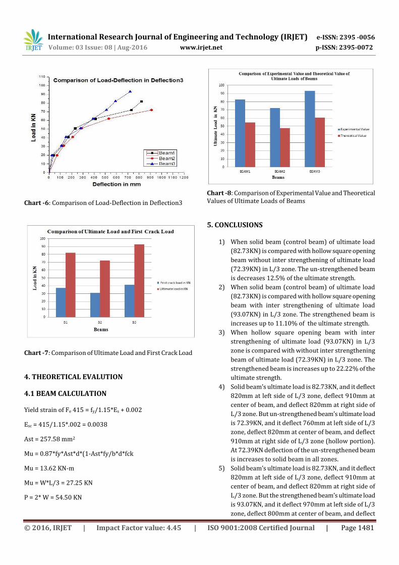
Chart -8: Comparison of Experimental Value and Theoretical Values of Ultimate Loads of Beams
5. CONCLUSIONS
1) When solid beam (control beam) of ultimate load
(82.73KN) is compared with hollow square opening
beam without inter strengthening of ultimate load
(72.39KN) in L/3 zone. The un-strengthened beam
is decreases 12.5% of the ultimate strength.
2) When solid beam (control beam) of ultimate load
(82.73KN) is compared with hollow square opening
beam with inter strengthening of ultimate load
(93.07KN) in L/3 zone. The strengthened beam is
increases up to 11.10% of the ultimate strength.
3) When hollow square opening beam with inter
strengthening of ultimate load (93.07KN) in L/3
zone is compared with without inter strengthening
beam of ultimate load (72.39KN) in L/3 zone. The
strengthened beam is increases up to 22.22% of the
ultimate strength.
4) Solid beam’s ultimate load is 82.73KN, and it deflect
820mm at left side of L/3 zone, deflect 910mm at
center of beam, and deflect 820mm at right side of
L/3 zone. But un-strengthened beam’s ultimate load
is 72.39KN, and it deflect 760mm at left side of L/3
zone, deflect 820mm at center of beam, and deflect
910mm at right side of L/3 zone (hollow portion).
At 72.39KN deflection of the un-strengthened beam
is increases to solid beam in all zones.
5) Solid beam’s ultimate load is 82.73KN, and it deflect
820mm at left side of L/3 zone, deflect 910mm at
center of beam, and deflect 820mm at right side of
L/3 zone. But the strengthened beam’s ultimate load
is 93.07KN, and it deflect 970mm at left side of L/3
zone, deflect 800mm at center of beam, and deflect

International Research Journal of Engineering and Technology (IRJET) e-ISSN: 2395 -0056
Volume: 03 Issue: 08 | Aug-2016 www.irjet.net p-ISSN: 2395-0072
© 2016, IRJET | Impact Factor value: 4.45 | ISO 9001:2008 Certified Journal | Page 1482
720mm at right side of L/3 zone (hollow portion).
At 82.73KN deflection of solid beam is increases to
strengthened beam in all zones.
6) Un-strengthened beam’s ultimate load is 72.39KN,
and it deflect 760mm at left side of L/3 zone, deflect
820mm at center of beam, and deflect 910mm at
right side of L/3 zone (hollow portion). But the
strengthened beam’s ultimate load is 93.07KN, and
it deflect 970mm at left side of L/3 zone, deflect
800mm at center of beam, and deflect 720mm at
right side of L/3 zone (hollow portion). At 72.39KN
deflection of un-strengthened beam is increases to
strengthened beam in all zones.
Here theoretical values of beams are compared with
experimental values of the beam.
1) Theoretical values of solid beams is 54.50 KN, and
experimental values of solid beam 83.73 KN.
Experimental values of solid beam is increases
34.90%.
2) Theoretical values of un-strengthened beams is
47.68 KN, and experimental values of un-
strengthened beam 72.39 KN. Experimental values
of un-strengthened beam is increases 34.13%.
3) Theoretical values of strengthened beams is 60.50
KN, and experimental values of strengthened
beam 93.07 KN. Experimental values of
strengthened beam is increases 34.99%.
ACKNOWLEDGEMENT
“The authors wish to thank the authorities of Visvesvaraya
Technological University for giving an opportunity to
conduct the experimental work in the concrete and highway
material laboratory of University B.D.T College of
Engineering, Davangere, Karnataka, India.”
REFERENCES [1] Jain Joy, Rajesh Rajeev (2014) “Effect of Reinforced
Concrete Beam with Hollow Neutral Axis’’ Department
of Structural Engineering & Construction Management
Department of Structural Engineering. IJSRD -
International Journal for Scientific Research &
Development| Vol. 2, Issue 10, 2014
[2] Susumu Inoue and Noriaki Egawa (1991) “Flexural and
shear behavior of reinforced concrete hollow beams
under reversed cyclic loads’’, KSCE Journal of Civil
Engineering (2014) 18(7):2162-2169
[3] G.Vasudevan, S.Kothandaraman, (2013) “Experimental
investigation on the performance of RC beams
strengthened with external bars at soffit’’, Materials and
Structures (2014) 47:1617–1631
[4] Lin-Hai Han, Xiao-Ling Zhao, You-Fu Yang, and Jiu-Bin
Feng (2003) “Experimental Study and Calculation of
Fire Resistance of Concrete-Filled Hollow Steel
Columns’’, JOURNAL OF STRUCTURAL ENGINEERING ©
ASCE / MARCH 2003
[5] Xiao-Ling Zhao and Gregory J. Hancock “Square And
Rectangular Hollow Sections Under Transverse End-
Bearing Force’’
[6] Mansur, Kiang-Hwee Tan and Wang (2006) “Analysis of
Concrete Beam With Circular Web Opening Using Strut-
and-Tie Models”
[7] Xiao-Ling Zhao, Gregory J. Hancock (1992) “Square And
Rectangular Hollow Sections Subject To Combined
Actions’’
[8] Poologanathan Keerthan and Mahen Mahendran (2015)
“Improving the Shear Capacities of Lipped Channel
Beams with Web Openings Using Plate Stiffeners’’